KR20080044251A - How to place a constraint on a deformation map and system implementing the method - Google Patents
How to place a constraint on a deformation map and system implementing the methodDownload PDFInfo
- Publication number
- KR20080044251A KR20080044251AKR1020087004293AKR20087004293AKR20080044251AKR 20080044251 AKR20080044251 AKR 20080044251AKR 1020087004293 AKR1020087004293 AKR 1020087004293AKR 20087004293 AKR20087004293 AKR 20087004293AKR 20080044251 AKR20080044251 AKR 20080044251A
- Authority
- KR
- South Korea
- Prior art keywords
- image
- deformation
- deformation map
- map
- images
- Prior art date
- Legal status (The legal status is an assumption and is not a legal conclusion. Google has not performed a legal analysis and makes no representation as to the accuracy of the status listed.)
- Ceased
Links
- 238000000034methodMethods0.000titleclaimsabstractdescription102
- 230000004044responseEffects0.000claimsabstractdescription6
- 230000005855radiationEffects0.000claimsdescription75
- 238000001959radiotherapyMethods0.000claimsdescription22
- 238000003384imaging methodMethods0.000claimsdescription20
- 230000007547defectEffects0.000claimsdescription5
- 230000001186cumulative effectEffects0.000claimsdescription4
- 238000002059diagnostic imagingMethods0.000claimsdescription4
- 238000009472formulationMethods0.000claims3
- 239000000203mixtureSubstances0.000claims3
- 238000011282treatmentMethods0.000description76
- 238000002591computed tomographyMethods0.000description31
- 230000008569processEffects0.000description29
- 230000003044adaptive effectEffects0.000description21
- 238000011269treatment regimenMethods0.000description14
- 238000000275quality assuranceMethods0.000description13
- 238000002595magnetic resonance imagingMethods0.000description11
- 230000033001locomotionEffects0.000description10
- 230000006854communicationEffects0.000description9
- 238000004891communicationMethods0.000description9
- 230000014509gene expressionEffects0.000description8
- 238000002721intensity-modulated radiation therapyMethods0.000description8
- QRYFCNPYGUORTK-UHFFFAOYSA-N4-(1,3-benzothiazol-2-yldisulfanyl)morpholineChemical compoundC1COCCN1SSC1=NC2=CC=CC=C2S1QRYFCNPYGUORTK-UHFFFAOYSA-N0.000description7
- 238000012795verificationMethods0.000description7
- 206010028980NeoplasmDiseases0.000description6
- 210000003484anatomyAnatomy0.000description6
- 238000002560therapeutic procedureMethods0.000description6
- 230000008901benefitEffects0.000description5
- 230000005540biological transmissionEffects0.000description5
- 238000004364calculation methodMethods0.000description4
- 238000002786image-guided radiation therapyMethods0.000description4
- 230000004048modificationEffects0.000description4
- 238000012986modificationMethods0.000description4
- 238000012636positron electron tomographyMethods0.000description4
- 210000002307prostateAnatomy0.000description4
- 230000002354daily effectEffects0.000description3
- 238000010586diagramMethods0.000description3
- 230000036541healthEffects0.000description3
- 210000000056organAnatomy0.000description3
- 238000012545processingMethods0.000description3
- 210000000664rectumAnatomy0.000description3
- 210000001519tissueAnatomy0.000description3
- 238000002604ultrasonographyMethods0.000description3
- 238000010521absorption reactionMethods0.000description2
- 230000008859changeEffects0.000description2
- 238000005516engineering processMethods0.000description2
- 230000006870functionEffects0.000description2
- 230000006855networkingEffects0.000description2
- 238000012831peritoneal equilibrium testMethods0.000description2
- 238000012877positron emission topographyMethods0.000description2
- 238000002203pretreatmentMethods0.000description2
- 230000001105regulatory effectEffects0.000description2
- 230000029058respiratory gaseous exchangeEffects0.000description2
- 238000002603single-photon emission computed tomographyMethods0.000description2
- 210000004872soft tissueAnatomy0.000description2
- 238000012546transferMethods0.000description2
- 230000009466transformationEffects0.000description2
- 206010011224CoughDiseases0.000description1
- 206010047571Visual impairmentDiseases0.000description1
- 238000009825accumulationMethods0.000description1
- 230000006978adaptationEffects0.000description1
- 238000004458analytical methodMethods0.000description1
- 230000003416augmentationEffects0.000description1
- 230000009286beneficial effectEffects0.000description1
- 230000007175bidirectional communicationEffects0.000description1
- 230000002457bidirectional effectEffects0.000description1
- 210000004204blood vesselAnatomy0.000description1
- 210000000988bone and boneAnatomy0.000description1
- 238000002725brachytherapyMethods0.000description1
- 238000013170computed tomography imagingMethods0.000description1
- 238000004883computer applicationMethods0.000description1
- 238000004590computer programMethods0.000description1
- 238000012937correctionMethods0.000description1
- 230000008878couplingEffects0.000description1
- 238000010168coupling processMethods0.000description1
- 238000005859coupling reactionMethods0.000description1
- 238000011161developmentMethods0.000description1
- 238000006073displacement reactionMethods0.000description1
- 229940079593drugDrugs0.000description1
- 239000003814drugSubstances0.000description1
- 230000000694effectsEffects0.000description1
- 238000010894electron beam technologyMethods0.000description1
- 230000003203everyday effectEffects0.000description1
- 238000002594fluoroscopyMethods0.000description1
- 230000006872improvementEffects0.000description1
- 230000000977initiatory effectEffects0.000description1
- 230000007246mechanismEffects0.000description1
- 238000009203neutron therapyMethods0.000description1
- 238000010943off-gassingMethods0.000description1
- 238000002727particle therapyMethods0.000description1
- 230000002093peripheral effectEffects0.000description1
- 238000007781pre-processingMethods0.000description1
- 238000002661proton therapyMethods0.000description1
- 230000001225therapeutic effectEffects0.000description1
Images


Classifications
- A—HUMAN NECESSITIES
- A61—MEDICAL OR VETERINARY SCIENCE; HYGIENE
- A61N—ELECTROTHERAPY; MAGNETOTHERAPY; RADIATION THERAPY; ULTRASOUND THERAPY
- A61N5/00—Radiation therapy
- A61N5/10—X-ray therapy; Gamma-ray therapy; Particle-irradiation therapy
- A—HUMAN NECESSITIES
- A61—MEDICAL OR VETERINARY SCIENCE; HYGIENE
- A61N—ELECTROTHERAPY; MAGNETOTHERAPY; RADIATION THERAPY; ULTRASOUND THERAPY
- A61N5/00—Radiation therapy
- A61N5/10—X-ray therapy; Gamma-ray therapy; Particle-irradiation therapy
- A61N5/103—Treatment planning systems
- A—HUMAN NECESSITIES
- A61—MEDICAL OR VETERINARY SCIENCE; HYGIENE
- A61N—ELECTROTHERAPY; MAGNETOTHERAPY; RADIATION THERAPY; ULTRASOUND THERAPY
- A61N5/00—Radiation therapy
- A61N5/10—X-ray therapy; Gamma-ray therapy; Particle-irradiation therapy
- A61N5/103—Treatment planning systems
- A61N5/1031—Treatment planning systems using a specific method of dose optimization
- A—HUMAN NECESSITIES
- A61—MEDICAL OR VETERINARY SCIENCE; HYGIENE
- A61N—ELECTROTHERAPY; MAGNETOTHERAPY; RADIATION THERAPY; ULTRASOUND THERAPY
- A61N5/00—Radiation therapy
- A61N5/10—X-ray therapy; Gamma-ray therapy; Particle-irradiation therapy
- A61N5/1048—Monitoring, verifying, controlling systems and methods
- A—HUMAN NECESSITIES
- A61—MEDICAL OR VETERINARY SCIENCE; HYGIENE
- A61N—ELECTROTHERAPY; MAGNETOTHERAPY; RADIATION THERAPY; ULTRASOUND THERAPY
- A61N5/00—Radiation therapy
- A61N5/10—X-ray therapy; Gamma-ray therapy; Particle-irradiation therapy
- A61N5/103—Treatment planning systems
- A61N2005/1041—Treatment planning systems using a library of previously administered radiation treatment applied to other patients
- A—HUMAN NECESSITIES
- A61—MEDICAL OR VETERINARY SCIENCE; HYGIENE
- A61N—ELECTROTHERAPY; MAGNETOTHERAPY; RADIATION THERAPY; ULTRASOUND THERAPY
- A61N5/00—Radiation therapy
- A61N5/10—X-ray therapy; Gamma-ray therapy; Particle-irradiation therapy
- A61N5/103—Treatment planning systems
- A61N5/1037—Treatment planning systems taking into account the movement of the target, e.g. 4D-image based planning
- A—HUMAN NECESSITIES
- A61—MEDICAL OR VETERINARY SCIENCE; HYGIENE
- A61N—ELECTROTHERAPY; MAGNETOTHERAPY; RADIATION THERAPY; ULTRASOUND THERAPY
- A61N5/00—Radiation therapy
- A61N5/10—X-ray therapy; Gamma-ray therapy; Particle-irradiation therapy
- A61N5/103—Treatment planning systems
- A61N5/1038—Treatment planning systems taking into account previously administered plans applied to the same patient, i.e. adaptive radiotherapy
- A—HUMAN NECESSITIES
- A61—MEDICAL OR VETERINARY SCIENCE; HYGIENE
- A61N—ELECTROTHERAPY; MAGNETOTHERAPY; RADIATION THERAPY; ULTRASOUND THERAPY
- A61N5/00—Radiation therapy
- A61N5/10—X-ray therapy; Gamma-ray therapy; Particle-irradiation therapy
- A61N5/1042—X-ray therapy; Gamma-ray therapy; Particle-irradiation therapy with spatial modulation of the radiation beam within the treatment head
- A—HUMAN NECESSITIES
- A61—MEDICAL OR VETERINARY SCIENCE; HYGIENE
- A61N—ELECTROTHERAPY; MAGNETOTHERAPY; RADIATION THERAPY; ULTRASOUND THERAPY
- A61N5/00—Radiation therapy
- A61N5/10—X-ray therapy; Gamma-ray therapy; Particle-irradiation therapy
- A61N5/1048—Monitoring, verifying, controlling systems and methods
- A61N5/1049—Monitoring, verifying, controlling systems and methods for verifying the position of the patient with respect to the radiation beam
- A—HUMAN NECESSITIES
- A61—MEDICAL OR VETERINARY SCIENCE; HYGIENE
- A61N—ELECTROTHERAPY; MAGNETOTHERAPY; RADIATION THERAPY; ULTRASOUND THERAPY
- A61N5/00—Radiation therapy
- A61N5/10—X-ray therapy; Gamma-ray therapy; Particle-irradiation therapy
- A61N5/1048—Monitoring, verifying, controlling systems and methods
- A61N5/1064—Monitoring, verifying, controlling systems and methods for adjusting radiation treatment in response to monitoring
- A61N5/1065—Beam adjustment
- A—HUMAN NECESSITIES
- A61—MEDICAL OR VETERINARY SCIENCE; HYGIENE
- A61N—ELECTROTHERAPY; MAGNETOTHERAPY; RADIATION THERAPY; ULTRASOUND THERAPY
- A61N5/00—Radiation therapy
- A61N5/10—X-ray therapy; Gamma-ray therapy; Particle-irradiation therapy
- A61N5/1048—Monitoring, verifying, controlling systems and methods
- A61N5/1064—Monitoring, verifying, controlling systems and methods for adjusting radiation treatment in response to monitoring
- A61N5/1069—Target adjustment, e.g. moving the patient support
Landscapes
- Health & Medical Sciences (AREA)
- Engineering & Computer Science (AREA)
- Biomedical Technology (AREA)
- Life Sciences & Earth Sciences (AREA)
- Nuclear Medicine, Radiotherapy & Molecular Imaging (AREA)
- Radiology & Medical Imaging (AREA)
- Pathology (AREA)
- Animal Behavior & Ethology (AREA)
- General Health & Medical Sciences (AREA)
- Public Health (AREA)
- Veterinary Medicine (AREA)
- Radiation-Therapy Devices (AREA)
- Processing Or Creating Images (AREA)
- Apparatus For Radiation Diagnosis (AREA)
- Image Generation (AREA)
Abstract
Description
Translated fromKorean본 발명은 변형 맵 상에 제약을 위치시키는 방법 및 그 방법을 구현하는 시스템에 관한 것이다.The present invention relates to a method of placing a constraint on a deformation map and a system implementing the method.
관련 출원Related Applications
본 출원은 "SYSTEM AND METHOD FOR FEEDBACK GUIDED QUALITY ASSURANCE AND ADAPTATION TO RADIATION THERAPY TREATMENT"를 명칭으로 하여 2005년 7월 22일자로 출원된 미국 특허 가출원 번호 60/701,580을 우선권으로 주장하며, 상기 출원의 전체 내용이 본 명세서에 원용되어 있다.This application claims priority to US Patent Provisional Application No. 60 / 701,580, filed Jul. 22, 2005, entitled "SYSTEM AND METHOD FOR FEEDBACK GUIDED QUALITY ASSURANCE AND ADAPTATION TO RADIATION THERAPY TREATMENT." Is incorporated herein by reference.
지난 수십 년에 걸쳐, 컴퓨터 및 네트워킹, 방사선 치료 계획 소프트웨어, 및 의료 촬상 방식(CT, MRI, US 및 PET)에서의 개량 장치들이 방사선 치료 요법에도 반영되어 왔다. 이러한 개량 장치는 영상 안내 방사선 치료 요법(IGRT : image guided radiation therapy)의 개발을 유도하였으며, IGRT는 건강한 기관에 대한 방사선 노출을 감소시키면서 방사선량이 더 우수하게 종양을 향하도록 하기 위해 환자의 내부의 해부학적 구조의 단면 영상을 이용하는 방사선 치료 요법이다. 종양에 전달된 방사선량은 방사선 빔의 크기, 형상 및 강도가 환자의 종양의 크기, 형 상 및 위치에 맞추어 변경되도록 하는 강도 조절 방사선 치료 요법(IMRT : intensity modulated radiation therapy)으로 조절된다. IGRT 및 IMRT는 종양을 둘러싸고 있는 건강한 조직에 대한 조사(irradiation)로 인한 심각한 부작용에 대한 가능성을 감소시키면서 종양에 대해서는 향상된 조절을 가능하게 한다.Over the past decades, improvements in computers and networking, radiation treatment planning software, and medical imaging modalities (CT, MRI, US, and PET) have been reflected in radiation therapy. This improved device has led to the development of image guided radiation therapy (IGRT), which is designed to reduce the exposure of radiation to healthy organs while providing better doses of radiation to the tumor. Radiation therapy using cross-sectional images of red structures. The amount of radiation delivered to the tumor is controlled by intensity modulated radiation therapy (IMRT), which allows the size, shape, and intensity of the radiation beam to change with the size, shape, and position of the patient's tumor. IGRT and IMRT allow for improved control of tumors while reducing the potential for serious side effects due to irradiation of healthy tissue surrounding the tumor.
IMRT는 여러 국가에서 건강보호(care)의 표준이 되고 있다. 그러나, 다수의 상황에서, IMRT는 시간, 자원 및 비용의 제약으로 인해 환자를 치료하기 위해 사용되지 않는다. IMRT 계획에 의해 생성된 높은 구배(high gradient)가 환자 치료를 위한 정확한 지점에 위치되도록 하기 위해 환자의 일일 영상(daily image)이 이용될 수 있다. 또한 이들 영상은 그 계획을 적합화시키기 위해 필요한 정보를 필요에 따라 온라인 또는 오프라인으로 제공할 수 있다.IMRT has become the standard of care in many countries. In many situations, however, IMRT is not used to treat patients due to time, resource and cost constraints. A daily image of the patient can be used to ensure that the high gradient generated by the IMRT plan is located at the correct point for patient treatment. These images can also provide the information needed to adapt the plan online or offline as needed.
환자를 치료하는 과정 동안 발생할 수 있는 불확실성 및 변화에 대한 다수의 제공원이 있다는 것은 방사선 치료의 분야에서는 널리 알려져 있다. 이들 발생원의 일부는 매일 매일의 환자의 셋업 위치(patient's setup position)에서의 작은 차이와 같은 랜덤한 에러를 나타낸다. 다른 발생원은 환자의 종양이 퇴행하거나 또는 환자가 치료 동안 체중이 감소되는 경우에 발생할 수도 있는 생리학적인 변화에 기인할 수 있다. 세 번째 가능한 카테고리는 움직임(motion)에 관한 것이다. 일부 움직임은 환자 기침 또는 가스 배출과 같이 더욱 랜덤하고 예측 가능하지 않을 것인 반면, 다른 움직임은 호흡 운동과 같이 더욱 규칙적으로 이루어질 수 있기 때문에, 움직임은 잠재적으로는 다른 카테고리 중의 하나와 중첩될 수 있다.It is well known in the field of radiation therapy that there are many sources of uncertainty and changes that can occur during the course of treating a patient. Some of these sources exhibit random errors, such as small differences in the patient's setup position every day. Another source may be due to physiological changes that may occur if the patient's tumor regresses or if the patient loses weight during treatment. The third possible category is motion. Since some movements may be more random and unpredictable, such as patient coughing or outgassing, while others may be more regular, such as breathing, movements may potentially overlap with one of the other categories. .
방사선 치료 요법에서, 불확실성은 환자의 치료의 퀄리티에 영향을 줄 수 있다. 예컨대, 표적 영역에 치료 방사선량(treatment dose)을 전달할 때, 표적 주위의 높은 방사선량 마진 영역(a high-dose "margin" area)도 함께 치료하는 것이 표준 시행법이다. 이것은 치료의 과정 동안 표적의 위치가 바뀌는 경우에도 또는 하나의 구간(single fraction) 동안에도 표적이 요구된 방사선량을 받게 되도록 하는 데 도움을 준다. 표적의 위치를 작게 한정할수록, 통상적으로 사용되도록 요구되는 마진은 더 커진다.In radiotherapy, uncertainty can affect the quality of treatment of a patient. For example, when delivering a treatment dose to a target area, it is standard practice to treat a high-dose "margin" area around the target as well. This helps to ensure that the target receives the required radiation dose even if the target's position changes during the course of treatment or even during a single fraction. The smaller the location of the target, the larger the margin typically required to be used.
적응형 방사선 치료 요법(adaptive radiation therapy)은 일반적으로 추후의 치료를 향상시키기 위해 방사선 치료 요법에 따른 치료의 과정 동안의 피드백을 이용하는 개념을 의미한다. 피드백은 오프라인 적응형 치료 요법 프로세스(on-line adaptive therapy process) 및 온라인 적응형 치료 요법 프로세스(off-line adaptive therapy process)에서 이용될 수 있다. 오프라인 적응형 치료 요법 프로세스는 환자가 치료 구간들 사이에 있을 때와 같이 치료되고 있지 않은 동안 발생한다. 이것의 한 가지 유형에서, 각각의 구간 동안, 각각의 구간 전 또는 후에 환자의 새로운 CT 영상이 획득된다. 최초의 몇몇 치료 구간으로부터 영상이 획득된 후, 이 영상은 표적 구조체의 여러 일자에 걸친 위치(multi-day location)의 유효 엔벨로프(effective envelope)를 결정하기 위해 평가된다. 그 후, 움직임의 표준 가정(canonical assumption)을 이용하기보다는 표적 구조체의 움직임의 범위를 더 우수하게 반영하기 위해 새로운 계획이 개발될 수 있다. 더욱 복잡한 버전의 오프라인 적응형 치료 요법은 각각의 구간 이후의 전달된 방사선량을 재계산하여 이들 방사선량을 누적하며, 이러한 누적 동안 변형 기술(deformation technology)을 이용하여 내부 움직임을 고려할 수 있다. 그리고나서, 누적 방사선량이 계획 방사선량과 비교될 수 있으며, 어떠한 불일치가 파악된다면, 후속 구간은 이러한 변화를 고려하도록 수정될 수 있다.Adaptive radiation therapy generally refers to the concept of using feedback during the course of treatment in accordance with radiation therapy to improve future treatment. Feedback may be used in the on-line adaptive therapy process and the off-line adaptive therapy process. The offline adaptive treatment regimen process occurs while not being treated, such as when the patient is between treatment intervals. In one type of this, during each interval, a new CT image of the patient is obtained before or after each interval. After images are obtained from the first few treatment intervals, the images are evaluated to determine the effective envelope of the multi-day location of the target structure. Thereafter, a new plan can be developed to better reflect the range of motion of the target structure rather than using the canonical assumption of motion. More complex versions of the offline adaptive treatment regimen recalculate the doses delivered after each interval, accumulating these doses, and during this accumulation, deformation techniques can be used to account for internal movement. The cumulative radiation dose can then be compared with the planned radiation dose, and if any discrepancies are identified, subsequent intervals can be modified to account for this change.
온라인 적응형 치료 요법 프로세스는 통상적으로 환자가 치료실 내에 있는 동안에 발생하며, 필수적이지는 않지만 치료 전달 동안에도 발생할 수 있다. 예컨대, 일부 방사선 치료 시스템(radiation therapy treatment system)은 온라인 CT 또는 x-선 시스템 등의 촬상 시스템이 설치된다. 이들 시스템은 치료 전에 치료 전달을 위한 환자의 셋업을 검증 또는 조정하기 위해 사용될 수 있다. 촬상 시스템은 또한 실제 치료 전달 동안 치료를 적합화하기 위해 사용될 수도 있다. 예컨대, 촬상 시스템은 환자의 해부학적 구조에서의 변화를 반영하기 위해 치료 전달을 수정하도록 치료와 동시에 사용될 수 있다.An online adaptive treatment regimen process typically occurs while the patient is in the treatment room and may, but not necessarily, also occur during treatment delivery. For example, some radiation therapy treatment systems are equipped with imaging systems such as online CT or x-ray systems. These systems can be used to verify or adjust the setup of a patient for treatment delivery prior to treatment. Imaging systems may also be used to tailor treatment during actual treatment delivery. For example, the imaging system can be used concurrently with the treatment to modify the treatment delivery to reflect changes in the patient's anatomy.
본 발명의 일특징은 적응형 치료 요법 기술의 적용을 위한 새로운 기회를 개시하며, 추가의 특징은 적응형 치료 요법을 위한 새로운 방법을 제시할 것이다. 구체적으로, 적응형 치료 요법은 통상적으로 환자의 치료를 수정하기 위해 피드백에 초점을 맞추지만, 본 발명은 퀄리티 보증 내용(quality assurance context)에 사용되는 적응형 치료 요법 프로세스에 초점을 맞춘다. 이것이 전체 시스템 검증의 점에서 특히 현실적이다.One feature of the present invention discloses new opportunities for the application of adaptive treatment regimens, and further features will present new methods for adaptive treatment regimens. In particular, while adaptive treatment regimens typically focus on feedback to modify a patient's treatment, the present invention focuses on the adaptive treatment regimen process used in a quality assurance context. This is particularly realistic in terms of full system verification.
예컨대, 환자를 통과한 치료 빔의 양을 나타내는 정보를 수집하기 위해 검출기가 사용될 수 있으며, 이로부터 전달을 위해 사용되는 어떠한 방사선 패턴뿐만 아니라 치료 출력(treatment output)의 크기(magnitude)가 결정될 수 있다. 이러한 전달 검증 프로세스의 이점은 부정확한 립 패턴(leaf pattern) 또는 기기 출력 등의 기기 전달(machine delivery)에서의 오류를 조작자가 검출할 수 있도록 해준다는 점이다.For example, a detector may be used to collect information indicative of the amount of treatment beam that has passed through the patient, from which the radiation output used for delivery as well as the magnitude of the treatment output may be determined. . An advantage of this delivery verification process is that it allows the operator to detect errors in machine delivery, such as inaccurate leaf patterns or machine outputs.
그러나, 기기가 적합하게 기능하고 있는지를 검증하는 것은, 기기를 프로그램하기 위해 사용된 외부 입력이 효과적이고 일관적인지를 검증할 필요가 있기 때문에, 그 자체가 치료 계획의 적합한 전달을 보증하지는 못한다. 그러므로, 본 발명의 일특징은 전체 치료 프로세스의 향상된 퀄리티 보증을 위한 적응형 피드백 루프의 광범위한 개념을 포함한다. 이 특징에서, 본 발명은 치료를 위해 환자를 위치시키고, 환자의 위치를 결정하기 위해 영상 안내 방법을 이용하는 단계, 영상 안내에 기초하여 치료를 위해 필요할 경우에 환자를 다시 위치시키는 단계, 및 치료를 개시하는 단계를 포함한다. 그 후, 치료 동안 또는 치료 후 중의 하나에서, 환자 방사선량(patient dose)을 재계산하고, 치료 전 또는 치료 동안에 수집되었던 환자 영상 정보를 통합한다. 이러한 단계의 완료 후, 전달이 계획된 바대로 수행되지 못한 정도를 분석하고, 계획된 전달이 신규로 이용 가능한 데이터에 비추어서 합리적이었는지를 검증하기 위해, 퀄리티 보증 데이터가 수집된다. 이러한 점에서, 피드백의 개념은 더 이상의 환자 내에서의 변화 또는 전달 시의 변화에 기초하여 치료에 대한 변화를 나타내기 위해 이용되지 않고, 원래의 전달 자체를 검증하기 위해 사용된다.However, verifying that the device is functioning properly does not in itself guarantee proper delivery of the treatment plan because it is necessary to verify that the external inputs used to program the device are effective and consistent. Therefore, one feature of the present invention encompasses the broad concept of an adaptive feedback loop for improved quality assurance of the entire treatment process. In this aspect, the present invention provides a method of positioning a patient for treatment, using an image guide method to determine the patient's position, repositioning the patient as needed for treatment based on the image guide, and Initiating. Then, either during treatment or after treatment, the patient dose is recalculated and the patient image information collected before or during treatment is integrated. After completion of these steps, quality assurance data is collected to analyze the extent to which delivery was not performed as planned and to verify that the planned delivery was reasonable in light of the newly available data. In this regard, the concept of feedback is no longer used to indicate changes in treatment based on changes in the patient or changes in delivery, but to verify the original delivery itself.
일례로서, 환자를 위해 치료 계획이 개발될 것이지만, 예컨대 부정확한 밀도 조절(density calibration)을 적용함에 의해서 그 계획을 위해 사용된 영상이 부적절하게 될 수 있다. 이 경우, 치료 계획은 부정확한 정보에 기초하게 될 것이며, 정확한 방사선량을 환자에게 전달하지 못할 수도 있다. 아직까지, 다수의 퀄리티 보증 기술은, 기기에 대한 명령이 정확한 입력 정보에 기초한 것인지를 검사하기보다는, 기기가 명령된 바대로 작동하는지를 검증할 것이기 때문에, 이러한 오류를 검출하지 못할 것이다. 마찬가지로, 일부 적응형 치료 요법 기술이 이러한 전달에 적용될 수 있지만, 이 예에서의 조절 문제가 지속된다면, 적응형 치료는 유사한 결함으로 곤란을 겪을 것이다.As an example, a treatment plan will be developed for the patient, but the image used for that plan may be inappropriate, for example, by applying inaccurate density calibration. In this case, the treatment plan will be based on inaccurate information and may not deliver the correct dose to the patient. So far, many quality assurance techniques will not detect this error because they will verify that the device is operating as commanded, rather than checking whether the command to the device is based on accurate input information. Likewise, some adaptive treatment regimens may be applied to this delivery, but if the control problem in this example persists, adaptive treatment will suffer from similar defects.
퀄리티 보증을 목적으로 피드백의 사용을 확장하기 위해 이용될 수 있는 다수의 기술이 존재한다. 예컨대, 일실시예에서, 이 프로세스는 전술한 전달 검증 기술을 포함할 것이다. 이들 방법이 제공하는 기기 성능의 검증은 전체 시스템의 퀄리티 검증 툴셋(toolset)의 유용한 성분이 된다. 또한, 전달 검증 프로세스는 끝이 절단된 시야각을 갖는 영상을 기반으로 하는 전달 기기와 같은 다른 시스템 오류를 분석하도록 확장될 수 있다.There are a number of techniques that can be used to extend the use of feedback for the purpose of quality assurance. For example, in one embodiment, this process will include the delivery verification technique described above. The verification of the device performance provided by these methods is a useful component of the overall system's quality verification toolset. In addition, the transfer verification process can be extended to analyze other system errors, such as a delivery device based on an image with a truncated viewing angle.
이러한 퀄리티 보증의 방법은 등록 기술 및 구체적으로 변형 가능한 등록(deformable registration) 기술을 이용함으로써 이점을 갖는다. 등록은 복수의 영상에 걸쳐 환자의 해부학 또는 생물학의 위치 간의 상관을 결정하는 방법이며, 변형 가능한 등록은 영상들, 상태들 또는 시간들 간의 해부학에서의 비강성 변화(non-rigid change)를 고려하기 위해 환자의 해부학 또는 생물학의 위치 간의 상관을 결정하는 방법이다. 전술한 바와 같이, 이러한 퀄리티 보증의 방법에서 중요한 단계는 온라인 이미지 및 기기로부터의 피드백에 기초하여 방사선량을 재계산하는 단계이다. 이들 방사선량을 분석할 때, 어떠한 오류가 악화되고 있는지 또는 이러한 오류가 서로 이주(mitigation)하고 있는지를 판정하기 위해 복수의 치료에 걸쳐 방사선량을 누적하는 것이 유용하다.This method of quality assurance has the advantage of using a registration technique and specifically a deformable registration technique. Registration is a method of determining the correlation between the position of a patient's anatomy or biology over a plurality of images, and the deformable registration takes into account non-rigid changes in anatomy between images, states or times. In order to determine the correlation between the position of the patient's anatomy or biology. As mentioned above, an important step in this method of quality assurance is the step of recalculating the radiation dose based on the online image and the feedback from the device. When analyzing these radiation doses, it is useful to accumulate radiation doses across multiple treatments to determine what errors are aggravating or whether these errors are migrating from one another.
이러한 퀄리티 보증 프로세스가 적응형 치료 요법 프로세스 없이도 적소에 적용될 수 있거나, 또는 적응형 치료 요법이 QA 방법 없이도 수행될 수 있다는 점에서, 본 명세서에서 제안된 발명이 근본적으로 적응형 치료 요법에 국한되지 않지만, 이러한 기술에 추가하여 적응형 치료 요법을 이용하는 것이 더 이득이 될 수 있다. 따라서, 전달 피드백을 이용함으로써 불일치가 파악되면, 이러한 불일치는 온라인으로 또는 구간들 사이에서 어떠한 수의 메카니즘에 의해 수정될 수 있다. 수정될 불일치는, 예컨대 프로세스와의 모순 또는 주어진 치료 계획을 위해 기기를 프로그래밍하기 위해 사용된 잘못된 입력에 대해 기기 자체에 의해 식별된 문제점 이상의 것이 될 있다.Although this quality assurance process can be applied in place without the adaptive treatment regimen process, or that the adaptive treatment regimen can be performed without the QA method, the invention proposed herein is not limited to adaptive treatment regimens in principle. In addition, it may be more beneficial to use adaptive therapy in addition to these techniques. Thus, if discrepancies are identified by using propagation feedback, these discrepancies can be corrected online or by any number of mechanisms between intervals. Inconsistencies to be corrected may be more than, for example, contradictions with the process or problems identified by the device itself for erroneous inputs used to program the device for a given treatment plan.
일실시예에서, 본 발명은 변형 맵(deformation map) 상에 제약(constraint)을 위치시키는 방법을 제공한다. 본 방법은, 2개의 영상 간의 변형 맵을 생성하는 단계, 상기 영상들 중의 하나의 영상에서 정의된 구조를 식별하는 단계, 하나의 영상으로부터의 정의된 구조를 다른 영상에 관련시키기 위해 변형 맵을 적용하여, 변형 기반의 정의된 구조(deformation-based defined structure)를 생성하는 단계, 상기 변형 기반의 정의된 구조를 수정하는 단계, 및 상기 변형 기반의 정의된 구조를 수정하는 단계에 응답하여 상기 변형 맵을 갱신하는 단계를 포함한다.In one embodiment, the present invention provides a method of placing a constraint on a deformation map. The method comprises the steps of generating a deformation map between two images, identifying a structure defined in one of the images, and applying a deformation map to associate the defined structure from one image to another image. Thereby generating the deformation-based defined structure, modifying the deformation-based defined structure, and modifying the deformation-based defined structure. Updating the;
또 다른 실시예에서, 본 발명은 변형 맵 상에 제약을 위치시키는 방법을 제공한다. 본 방법은, 2개의 영상 간의 변형 맵을 생성하는 단계, 상기 영상들 중의 하나의 영상에서 정의된 구조를 식별하는 단계, 하나의 영상으로부터의 정의된 구조를 다른 영상에 관련시키기 위해 변형 맵을 적용하여, 변형 기반의 정의된 구조를 생성하는 단계, 상기 변형 기반의 정의된 구조를 수정하는 단계, 상기 변형 기반의 정의된 구조를 수정하는 단계에 응답하여 상기 변형 맵을 갱신하는 단계, 및 갱신된 상기 변형 맵에 기초하여 윤곽을 생성하는 단계를 포함한다.In yet another embodiment, the present invention provides a method for placing constraints on a deformation map. The method comprises the steps of generating a deformation map between two images, identifying a structure defined in one of the images, and applying a deformation map to associate the defined structure from one image to another image. Generating a deformation based defined structure, modifying the deformation based defined structure, updating the deformation map in response to modifying the deformation based defined structure, and updated Generating an outline based on the deformation map.
본 발명의 또 다른 실시예에서, 본 발명은 변형 맵 상에 제약을 위치시키는 방법을 제공한다. 본 방법은, 제1 윤곽 세트를 생성하는 단계, 제2 윤곽 세트를 생성하는 단계, 및 상기 제1 윤곽 세트와 상기 제2 윤곽 세트 간의 변형 맵을 생성하는 단계를 포함한다.In another embodiment of the present invention, the present invention provides a method for placing a constraint on a deformation map. The method includes generating a first set of outlines, generating a second set of outlines, and generating a deformation map between the first set of outlines and the second set of outlines.
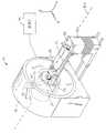
도 1은 방사선 치료 시스템의 사시도이다.1 is a perspective view of a radiation treatment system.
도 2는 도 1에 도시된 방사선 치료 시스템에 사용될 수 있는 다엽 시준기(multi-leaf collimator)의 사시도이다.FIG. 2 is a perspective view of a multi-leaf collimator that may be used in the radiation treatment system shown in FIG. 1.
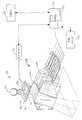
도 3은 도 1의 방사선 치료 시스템의 개략도이다.3 is a schematic diagram of the radiation treatment system of FIG. 1.
도 4는 본 발명의 일실시예에 따라 변형 맵 상에 제약을 위치시키는 방법의 방사선 치료 시스템에 사용된 소프트웨어 프로그램의 개략도이다.4 is a schematic diagram of a software program used in a radiation therapy system of a method for placing a constraint on a deformation map in accordance with one embodiment of the present invention.
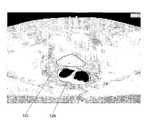
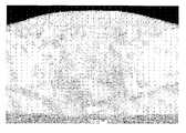
도 5는 윤곽(contour)을 포함하는 환자의 계획 영상이다.5 is a plan image of a patient including a contour.
도 6은 수동으로 그려진 윤곽을 포함하는 환자의 처리전 영상이다.6 is a pre-treatment image of a patient including manually drawn contours.
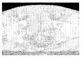
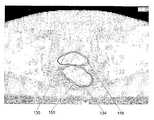
도 7은 도 5에서의 영상과 도 6에서의 영상 간의 변형 맵이다.FIG. 7 is a deformation map between the image of FIG. 5 and the image of FIG. 6.
도 8은 도 7에 예시된 변형 맵을 적용한 후의 윤곽을 포함하는 환자의 결과 영상이다.FIG. 8 is a result image of a patient including a contour after applying the deformation map illustrated in FIG. 7.
도 9는 도 6의 수동으로 그려진 윤곽을 제약으로써 이용하는 변형 맵이다.9 is a deformation map that uses the manually drawn outline of FIG. 6 as a constraint.
도 10은 도 9에 예시된 변형 맵을 적용한 후의 윤곽을 포함하는 환자의 결과 영상이다.FIG. 10 is a result image of a patient including a contour after applying the deformation map illustrated in FIG. 9.
도 11은 본 발명의 일실시예에 따라 변형 맵 상에 제약을 위치시키는 방법의 흐름도이다.11 is a flowchart of a method for placing constraints on a deformation map in accordance with one embodiment of the present invention.
도 12는 본 발명의 일실시예에 따라 변형 맵 상에 제약을 위치시키는 방법의 흐름도이다.12 is a flowchart of a method for placing constraints on a deformation map in accordance with one embodiment of the present invention.
도 13은 본 발명의 일실시예에 따라 변형 맵 상에 제약을 위치시키는 방법의 흐름도이다.13 is a flow diagram of a method for placing constraints on a deformation map in accordance with one embodiment of the present invention.
본 발명은 이하의 상세한 설명 및 첨부 도면을 참조하면 더욱 명확하게 될 것이다.The present invention will become more apparent with reference to the following detailed description and accompanying drawings.
본 발명의 실시예들을 구체적으로 설명하기에 앞서, 본 발명은 그 용용범위가 이하의 상세한 설명에 언급되거나 또는 첨부 도면에 예시되어 있는 상세 구성 또는 구성요소의 배치로 한정되지 않음에 유의하기 바란다. 본 발명은 다른 실시 형태로 구현될 수도 있으며, 다양한 방식으로 사용되거나 실행될 수 있다. 또한, 본 명세서 내에 사용된 표현 또는 용어는, 단지 설명을 위한 것이며, 본 발명을 이 러한 것으로 한정하려는 것은 아니다. 본 명세서 내의 "구성되는", "포함하는" 또는 "갖는"이라는 표현과 그 유사 표현은 그 다음에 나열되는 항목 및 그 등가의 요소뿐만 아니라 추가의 항목을 모두 포함하는 것을 의미한다. 또한, "탑재", "연결", "지지" 및 "결합"이라는 표현과 그 유사 표현은, 특별히 다른 의미로 지정되거나 한정되지 않는 경우에는, 포괄적인 의미로 사용되며, 직간접적인 장착, 연결, 지지 및 결합 모두를 포함한다. 또한, "연결" 및 "결합"은 물리적 또는 기계적인 연결 및 결합으로 한정되지 않는다.Before describing the embodiments of the present invention in detail, it should be noted that the scope of the present invention is not limited to the details or arrangement of components mentioned in the following detailed description or illustrated in the accompanying drawings. The invention may be embodied in other embodiments and may be used or executed in various ways. Also, the phraseology or terminology used herein is for the purpose of description and should not be regarded as limiting. The expression “comprising”, “comprising” or “having” and similar expressions in this specification are meant to include all items additionally, as well as the items listed thereafter and their equivalents. In addition, the expressions "mounting", "connection", "support" and "combination" and similar expressions are used in a comprehensive sense unless specifically designated or limited to other meanings, and are used for direct or indirect mounting, connecting, It includes both support and engagement. In addition, "connection" and "bonding" are not limited to physical or mechanical connection and coupling.
본 명세서에서는 첨부 도면을 설명함에 있어서 상부, 하부, 상방향, 하방향, 후방향, 저부, 전방, 후방 등의 방향을 나타내는 표현이 사용되고 있지만, 이들 표현은 편의를 위해 도면에 대한 상대적인 방향(정상적으로 봤을 때)을 나타낸다. 따라서, 이러한 방향을 표현 그대로 받아들이거나 본 발명을 임의의 형태로 한정하는 것으로 간주하여서는 안된다. 또한, 본 명세서에서는 설명을 위해 "제1", "제2" 및 "제3" 등의 표현이 사용되고 있으며, 이들 표현은 상대적인 중요도를 나타내거나 암시하는 것으로 간주되지 않아야 한다.In the present specification, in describing the accompanying drawings, an expression indicating a direction such as upper, lower, upward, downward, rearward, bottom, front, rear, and the like is used. See). Accordingly, this direction is not to be taken as an expression or to limit the present invention to any form. Also, in this specification, expressions such as “first”, “second”, and “third” are used for description, and these expressions should not be regarded as indicating or implying relative importance.
또한, 하드웨어, 소프트웨어, 및 전자 부품이나 모듈을 포함하는 본 발명의 실시예의 구성요소의 대부분이 하드웨어로만 구현되는 것으로 도시 및 개시되어 있지만, 본 발명의 기술 분야에 익숙하고 본 명세서의 상세한 설명에 대한 이해를 기반으로 하고 있는 사람은, 적어도 일실시예에서, 본 발명의 전자 공학을 기반으로 하는 특징이 소프트웨어로 구현될 수도 있음을 인지할 것이다. 이와 같이, 본 발명을 구현하기 위해 복수의 하드웨어 및 소프트웨어를 기반으로 하는 장치뿐만 아 니라 복수의 상이한 구조의 부품이 이용될 수 있음을 이해할 수 있을 것이다. 또한, 이하의 설명에서 언급되는 바와 같이, 도면에 도시된 구체적인 기계적 구성은 본 발명의 실시예를 예시하기 위한 것이며, 다른 기계적인 구성 또한 이용 가능하다.In addition, although many of the components of embodiments of the present invention, including hardware, software, and electronic components or modules, are shown and described as being implemented only in hardware, those skilled in the art are familiar with the detailed description herein. Persons based on the understanding will recognize that, in at least one embodiment, features based on the electronics of the present invention may be implemented in software. As such, it will be appreciated that a plurality of different structured components as well as devices based on a plurality of hardware and software may be used to implement the present invention. In addition, as mentioned in the following description, the specific mechanical configurations shown in the drawings are intended to illustrate embodiments of the present invention, and other mechanical configurations are also available.
도 1은 환자(14)에게 방사선 치료를 제공할 수 있는 방사선 치료 시스템(10)을 도시하고 있다. 방사선 치료 요법은 광자를 기반으로 하는 방사선 치료 요법, 근접 치료 요법(brachytherapy), 전자빔 치료 요법, 양자, 중성자 또는 입자 치료 요법, 또는 다른 유형의 치료 요법을 포함할 수 있다. 방사선 치료 시스템(10)은 갠트리(gantry, 18)를 포함한다. 갠트리(18)는 방사선 모듈(22)을 포함하며, 방사선 모듈(22)은 방사선빔(30)을 생성하도록 동작할 수 있는 방사선 소스(24) 및 선형 가속기(26)를 포함할 수 있다. 도면에 도시된 갠트리(18)는 환형 갠트리, 즉 360°회전의 원호를 이루면서 연장하는 완전한 환형 또는 원형의 갠트리이지만, 다른 유형의 구성도 가능할 것이다. 예컨대, C-타입, 부분적으로 환형을 이루고 있는 갠트리, 또는 로봇 팔도 이용될 수 있다. 환자(14)에 대해 다양한 회전 위치 및/또는 축 위치에 방사선 모듈(22)을 위치시킬 수 있는 어떠한 다른 구조물도 이용될 수 있다. 또한, 방사선 소스(24)는 갠트리(18)의 형상을 따르지 않는 경로로 이동할 수도 있다. 예컨대, 방사선 소스(24)는 도시된 갠트리(18)가 전반적으로 원형의 형상을 이루는 경우에도 원형이 아닌 다른 경로로 이동할 수도 있다.1 shows a
방사선 모듈(22)은 또한 방사선빔(30)을 수정하거나 조절하도록 작동할 수 있는 조절 장치(34)를 포함할 수 있다. 조절 장치(34)는 방사선빔(30)에 대한 조 절을 제공하며, 방사선빔(30)을 환자(14)에게 지향시킨다. 구체적으로, 방사선빔(34)은 환자의 일부 부위에 지향된다. 폭넓게 말하자면, 환자의 부위는 환자의 신체 전부를 의미할 수도 있지만, 일반적으로는 신체 전부보다는 작으며, 2차원의 면적 및/또는 3차원의 체적으로 정의될 수 있는 부분을 의미한다. 표적(38) 또는 표적 영역으로도 지칭될 수 있는 방사선을 쪼이도록 요구되는 부위는 대상 영역의 일례이다. 다른 유형의 대상 영역으로는 위험 영역(region of risk)이 있다. 환자의 부위가 위험 영역을 포함한다면, 방사선빔은 그 위험 영역을 향하지 않도록 하는 것이 바람직하다. 환자(14)는 방사선 치료를 필요로 하는 표적 영역을 하나 이상 가질 수도 있다. 이러한 조절은 강도 조절 방사선 치료 요법(IMRT)으로서 지칭된다.The
조절 장치(34)는 도 2에 도시된 바와 같이 시준 장치(42)를 포함할 수 있다. 시준 장치(42)는 방사선빔(30)이 통과할 수도 있는 애퍼쳐(50)의 크기를 결정하고 조정하는 한 세트의 조오(jaw, 46)를 포함한다. 조오(46)는 상위 조오(54) 및 하위 조오(58)를 포함한다. 상위 조오(54) 및 하위 조오(58)는 애퍼쳐(50)의 크기를 조정하기 위해 이동할 수 있다.The adjusting
일실시예에서, 도 2에 도시된 바와 같이, 조절 장치(34)는 강도 조절을 제공하기 위해 다엽 시준기(62)를 포함할 수 있으며, 다엽 시준기(62)는 한 위치에서 다른 위치로 이동하도록 동작할 수 있는 서로 엇갈려 배치된 복수의 엽부(interlaced leaf, 66)를 포함한다. 엽부(66)는 최소 개방 위치와 최대 개방 위치 사이의 어느 곳의 위치로도 이동될 수 있다. 복수의 엽부(66)는 방사선빔(30) 이 환자(14) 위의 표적(38)에 도달하기 전에 방사선빔(30)의 세기, 크기 및 형상을 조절한다. 각각의 엽부(66)는, 방사선의 통과를 허용 또는 차단하기 위해 신속하게 개방 및 폐쇄될 수 있도록 모터 또는 에어 밸브 등의 액추에이터(70)에 의해 독립적으로 제어된다. 액추에이터(70)는 컴퓨터(74) 및/또는 컨트롤러에 의해 제어될 수 있다.In one embodiment, as shown in FIG. 2, the
방사선 치료 시스템(10)은 또한 예컨대 방사선빔(30)을 수신하도록 동작할 수 있는 예컨대 킬로볼트 또는 메가볼트 검출기 등의 검출기(78)를 포함할 수 있다. 선형 가속기(26) 및 검출기(78)는 또한 CT 시스템으로서 동작하여 환자(14)의 CT(컴퓨터 단층 촬영) 영상을 생성할 수 있다. 선형 가속기(26)는 방사선빔(30)을 환자(14)의 표적(38)을 향해 방출한다. 표적(38)은 방사선의 일부를 흡수한다. 검출기(78)는 표적(38)에 의해 흡수된 방사선의 양을 검출하거나 측정한다. 검출기(78)는 선형 가속기(26)가 환자(14) 주변을 회전하고 환자(14)를 향해 방사선을 방출할 때에 상이한 각도로부터 흡수 데이터를 수집한다. 수집된 흡수 데이터는 흡수 데이터를 처리하여 환자의 인체 조직 및 기관에 대한 영상을 생성하기 위해 컴퓨터(74)에 전송된다. 이 영상은 뼈, 연조직(soft tissue) 및 혈관을 보여줄 수 있다.The
CT 영상은 부채 모양(fan-shaped)의 형상, 멀티-슬라이스(multi-slice) 형상 또는 콘-빔(cone-beam) 형상을 갖는 방사선빔(30)으로 획득될 수 있다. 또한, CT 영상은 메가볼트의 에너지 또는 킬로볼트의 에너지를 전달하는 선형 가속기(26)로 획득될 수 있다. 획득된 CT 영상은 이전에 획득된 CT 영상(방사선 치료 시스 템(10) 또는 다른 CT 스캐너, MRI 시스템 및 PET 시스템 등의 다른 영상 획득 장치로부터의 영상)과 함께 등록될 수 있음에 유의하기 바란다. 예컨대, 환자(14)에 대해 이전에 획득된 CT 영상은 콘투어링 프로세스(contouring process)를 통해 이루어진 식별된 표적(38)을 포함할 수 있다. 환자(14)에 대해 신규로 획득된 CT 영상은 새로운 CT 영상에서 표적(38)을 식별하는 데 도움을 주기 위해 이전에 획득된 CT 영상과 함께 등록될 수 있다. 등록 처리는 강성의 또는 변형 가능한 등록 툴(rigid or deformable registration tool)을 이용할 수 있다.The CT image may be obtained as a
일부 실시예에서, 방사선 치료 시스템(10)은 x-선 소스 및 CT 영상 검출기를 포함할 수 있다. x-선 소스 및 CT 영상 검출기는 전술한 바와 같은 선형 가속기(26) 및 검출기(28)와 유사한 방식으로 동작하여 영상 데이터를 획득한다. 영상 데이터는 컴퓨터(74)에 전송되며, 이 컴퓨터에서 환자의 신체 조직 및 기관에 대한 영상을 생성하도록 처리된다.In some embodiments, the
방사선 치료 시스템(10)은 또한 환자(14)를 지지하는 진료대(82)(도 1에 도시됨)와 같은 환자 지지부를 포함할 수 있다. 진료대(82)는 적어도 하나의 축(84)을 따라 x, y 또는 z 방향으로 이동한다. 본 발명의 다른 실시예에서, 환자 지지부는 환자의 신체의 특정 부위를 지지하도록 구성된 장치도 가능하다. 환자 지지부(82)는 환자의 전체 신체를 지지하여야 하도록 제한되지는 않는다. 방사선 치료 시스템(10)은 또한 진료대(82)의 위치를 조작하도록 동작할 수 있는 전동 시스템(86)을 포함할 수 있다. 전동 시스템(86)은 컴퓨터(74)에 의해 제어될 수 있다.The
도 2 및 도 3에 도시된 컴퓨터(74)는 다양한 소프트웨어 프로그램을 실행하 기 위한 오퍼레이팅 시스템 및/또는 통신 어플리케이션을 포함한다. 구체적으로, 컴퓨터(74)는 방사선 처리법 처리 시스템(10)과 통신하도록 동작하는 소프트웨어 프로그램(90)을 포함할 수 있다. 소프트웨어 프로그램(90)은 외부의 소프트웨어 프로그램 및 하드웨어로부터 데이터를 수신하도록 동작할 수 있으며, 또한 이러한 데이터가 소프트웨어 프로그램(90)에 입력될 수도 있다.The
컴퓨터(74)는 의료인에 의해 액세스되도록 구성된 적합한 입력/출력 장치를 포함할 수 있다. 컴퓨터(74)는 프로세서, I/O 인터페이스, 및 기억 장치 또는 메모리 등의 대표적인 하드웨어를 포함할 수 있다. 컴퓨터(74)는 또한 키보드 및 마우스와 같은 입력 장치를 포함할 수 있다. 컴퓨터(74)는 또한 모니터와 같은 표준 출력 장치를 포함할 수 있다. 그 외에, 컴퓨터(74)는 프린터 및 스캐너와 같은 주변 장치를 포함할 수 있다.
컴퓨터(74)는 다른 컴퓨터(74) 및 방사선 치료 시스템(10)과 네트워크 연결될 수 있다. 다른 컴퓨터(74)는 추가적인 및/또는 상이한 컴퓨터 프로그램 및 소프트웨어를 포함할 수 있으며, 본 명세서에 설명된 컴퓨터(74)와 동일하도록 요구되지는 않는다. 컴퓨터(74)와 방사선 치료 시스템(10)은 네트워크(94)로 통신할 수 있다. 컴퓨터(74) 및 방사선 치료 시스템(10)은 또한 데이터베이스(98) 및 서버(102)와 통신할 수 있다. 소프트웨어 프로그램(90)은 서버(102)에 상주할 수도 있다.
네트워크(94)는 어떠한 네트워킹 기술이나 토폴로지 또는 이러한 기술과 토폴로지의 조합으로도 구축될 수 있으며, 복수의 하위 네트워크를 포함할 수 있다. 도 3에 도시된 컴퓨터와 시스템 간의 연결은 근거리 통신망(LAN), 광역 통신망(WAN), 공중 전화망(PSTN), 무선 네트워크, 인터넷, 인트라넷, 또는 다른 적합한 네트워크를 통해 이루어질 수 있다. 병원 또는 의료 시설에서, 도 3에 도시된 컴퓨터와 시스템 간의 통신은 "Health Level 7"(HL 7) 프로토콜 또는 다른 버젼의 프로토콜 및/또는 다른 요구된 프로토콜을 통해 이루어질 수 있다. HL7은, 의료 환경에서의 전자 데이터의 교환을 위해 상이한 공급자(vendor)들로부터의 2개의 컴퓨터 어플리케이션(발송측 및 수신측) 간의 인터페이스의 구현을 지정하는 표준 프로토콜이다. HL7에 의해, 의료 시설(health care institution)이 상이한 어플리케이션 시스템으로부터의 핵심 세트의 데이터를 교환하는 것이 가능하게 된다. 구체적으로, HL7은 교환될 데이터, 교환의 시기, 어플리케이션에 대한 오류의 통신에 대해 규정할 수 있다. 그 포맷은 특성상 일반적인 포맷이며, 관련된 어플리케이션의 요구를 충족하도록 구성될 수 있다.The
또한, 도 3에 도시된 컴퓨터와 방사선 치료 시스템 간의 통신은, 임의 버전의 DICOM(Digital Imaging and Communications in Medicine) 프로토콜 및/또는 다른 필요한 프로토콜에 의해 이루어질 수도 있다. DICOM 프로토콜은, 국제 전자기기 제조 협회(NEMA : National Electrical Manufacturers Association)에서 개발한 국제 통신 표준으로서, 의료 장비의 여러 부품 사이에서 의료 영상에 관련된 데이터(medical image-related data)를 전송하는데 사용되는 포맷을 규정하고 있다. DICOM RT는 방사선 치료 관련 데이터에 전용으로 사용되는 표준을 의미한다.In addition, communication between the computer and the radiation therapy system shown in FIG. 3 may be by any version of the Digital Imaging and Communications in Medicine (DICOM) protocol and / or other necessary protocols. The DICOM protocol is an international communication standard developed by the National Electrical Manufacturers Association (NEMA) and is a format used to transfer medical image-related data between components of medical equipment. It is prescribed. DICOM RT refers to a standard dedicated to radiation-related data.
도 3의 양방향 화살표는, 도 3에 도시된 네트워크(94), 컴퓨터(74) 중의 하 나, 및 방사선 치료 시스템(10) 간의 양방향의 통신 및 정보 전송을 나타낸다. 그러나, 몇몇 의료 장비 및 컴퓨터화된 장비에 대해서는, 단방향의 통신 및 정보 전송만을 필요로 할 수 있다.The bidirectional arrows in FIG. 3 indicate bidirectional communication and information transmission between the
소프트웨어 프로그램(90)은 방사선 치료 프로세스의 기능을 수행하기 위해 다른 모듈과 통신하는 도 4에 도시된 복수의 모듈을 포함한다. 각종 모듈들은, 2개의 영상의 변형 맵을 생성하고 영상들 중의 하나의 영상의 다양한 수정에 응답하여 변형 맵을 수정하기 위해 서로 통신한다. 일반적으로, 변형 프로세스는 치료 전달을 시행하기 전에 발생한다. 하술되는 모듈의 전부가 서로 통신하고 전술한 각종 기능을 수행하도록 요구되는 것은 아니라는 것에 유의하기 바란다.The
소프트웨어 프로그램(90)은 의료인에 의해 이루어진 방사선 치료 시스템(10)에 대한 데이터 입력에 기초하여 환자(14)에 대한 치료 계획을 생성하도록 동작 가능한 치료 계획 모듈(106)을 포함한다. 데이터는 환자(14)의 적어도 일부분에 대한 하나 이상의 영상(예컨대, 계획 영상 및/또는 치료전 영상)을 포함한다. 치료 계획 모듈(106)은 치료를 복수의 구간으로 분할하고, 의료인에 의해 입력된 처방에 기초하여 각각의 구간 또는 치료에 대한 방사선량을 결정한다. 치료 계획 모듈(106)은 또한 표적(38) 주변을 묘사하고 있는 다양한 윤곽(contour)에 기초하여 표적(38)에 대한 방사선량을 결정한다. 복수의 표적(38)이 존재하여 동일한 치료 계획에 포함될 수도 있다.The
소프트웨어 프로그램(90)은 환자의 적어도 일부분에 대한 영상을 획득하도록 동작할 수 있는 촬상 모듈(110)을 포함한다. 치료 계획을 전달하기에 앞서, 촬상 모듈(110)은 치료를 시행하기 전에 환자(14)에 대한 하나 이상의 치료전 영상을 획득하도록 CT 촬상 장치와 같은 온보드 촬상 장치에 지시할 수 있다. 비정량적인 CT(non-quantitative CT), MRI, PET, SPECT, 초음파, 투과 촬상 장치, 형광 투시 장치(fluoroscopy), RF-기반 국소 촬상 장치 등과 같은, 환자(14)의 치료전 영상을 획득하기 위해 다른 오프라인 촬상 장치 또는 시스템이 사용될 수도 있다. 획득된 치료전 영상은 환자(14)의 등록을 위해 및/또는 하나 이상의 계획 영상과 하나 이상의 치료전 영상 간의 차이를 식별하기 위해 변형 맵을 생성하기 위해 사용될 수 있다.The
소프트웨어 프로그램(90)은 또한, 영상의 변형 맵을 생성하기 위해, 촬상 모듈(110) 및 치료 계획 모듈(106)로부터의 영상 데이터 및 치료 계획 모듈(106)로부터의 다른 환자 및 시스템 데이터 등의 데이터를 수신하도록 동작할 수 있는 변형 모듈(114)을 포함한다. 변형 모듈(114)은 전달된 치료의 전부에 대해 방사선량의 누적치를 결정하기 위해 변형 기술을 이용할 수 있다.The
변형 맵은 방사선량 계산을 위해 복수의 영상들을 관련시키기 위해 이용될 수 있다. 예컨대, 변형 맵은, 방사선량 계산에 유용한 계획 영상과, 정성적인 값(qualitative value)을 갖지만 방사선량 계산에 대해서는 직접적인 활용성을 거의 갖지 않는 온라인 영상을 관련시킬 수 있다. 이러한 관계는, 더욱 정량적인 영상(more quantitative image)을, 온라인 영상 또는 거의 정량적이지 않은 영상의 정성적인 형태로 "재맵핑"하기 위해 사용될 수 있다. 그 결과의 재맵핑된 영상은, 제1 영상의 정량적인 이점을 가질뿐만 아니라 제2 영상에 포함된 바와 같은 갱신된 해부학적 정보를 가질 것이기 때문에, 방사선량 계산 또는 정량적 응용에 대해서 계획 영상 또는 온라인 영상 중의 어느 것보다도 더욱 적합하게 될 것이다. 이것은, 제1 영상(즉, 계획 영상)이 CT 영상이고, 제2 영상이 정량적인 영상 값(예컨대, MRI, PET, SPECT, 초음파 또는 비정량적인 CT 등의 영상)이 결여되어 있는 경우과 같은 다양한 케이스에 유용하게 될 것이다. 변형 맵은 또한, 환자(14)에게 전달된 방사선량을 결정하기 위해, 3D 영상(예컨대, 계획 영상 또는 처리전 영상) 등의 참조 영상과 4D CT 영상 등의 시간을 기반으로 하는 일련의 영상들을 관련시킬 수 있다.The deformation map can be used to relate the plurality of images for the radiation dose calculation. For example, the deformation map may associate a plan image useful for the radiation dose calculation with an online image having a qualitative value but having little direct utility for the radiation dose calculation. This relationship can be used to "remap" a more quantitative image into a qualitative form of an on-line image or an image that is rarely quantitative. The resulting remapped image will not only have the quantitative advantages of the first image, but will also have updated anatomical information as included in the second image, so that the planned image or online for radiation dose calculation or quantitative application It will be more suitable than any of the images. This can be various, such as when the first image (i.e., planned image) is a CT image and the second image lacks quantitative image values (e.g., images such as MRI, PET, SPECT, ultrasound or non-quantitative CT). It will be useful for the case. The deformation map also includes a series of images based on time, such as a reference image, such as a 3D image (eg, a plan image or a pre-process image), and a 4D CT image, to determine the radiation dose delivered to the
변형 모듈(114)은, 정량적인 한계 대신에 또는 정량적인 한계에 추가하여, 기하학적 왜곡, 결함 및/또는 불완전성(incompleteness)을 정정할 수 있다. 예컨대, 해부학적 구조를 잘 보여주기는 하지만 기하학적 왜곡을 포함하는 현재의 MRI 영상이, 왜곡되지 않은 CT 영상으로 재맵핑될 수도 있다. 또는, 해부학적 변화를 보여주면서 왜곡을 동시에 정정하기 위해 복수의 영상이 이용될 수 있다.The
변형 맵은 계획 영상 이후에 획득된 환자 영상에 대해 방사선량을 계산하기 위해 사용될 수 있다. 또한, 변형 맵은 복수의 전달된 구간에 대한 방사선량을 누적하는 데 유용하다. 이러한 방사선량은 물리적인 공간에서의 방사선량의 지점에 기초하여 가산될 수 있지만, 또 다른 방법으로는, 구조체가 위치를 변경한 경우에도 방사선량을 받은 구조체에 기초하여 방사선량을 가산하기 위해 변형 방법을 프로세스에 통합시키는 방법이 있다. 변형 모듈(114)은 이전에 전달된 구간으로부터 환자(14)가 받은 방사선량을 계산할 수 있다.The deformation map can be used to calculate the radiation dose for the patient image obtained after the planned image. The deformation map is also useful for accumulating radiation dose for a plurality of delivered intervals. This radiation dose can be added based on the point of radiation dose in the physical space, but alternatively, it is modified to add the radiation dose based on the radiation dosed structure even when the structure is repositioned. There is a way to integrate the method into the process. The modifying
변형 맵은 표적(38) 주변의 윤곽을 정의하기 위해 생성될 수 있다. 소프트웨어 프로그램(90)은 영상에 대한 하나 이상의 윤곽을 생성하도록 동작할 수 있는 윤곽 모듈(118)을 포함할 수 있다. 일반적으로, 의료인은 계획 영상 위의 표적(38) 주변의 윤곽을 수동으로 규정한다. 이 프로세스는 시간이 많이 소요된다. 신규 획득된 영상(예컨대, 처리전 영상)은 정의된 윤곽을 갖지 못한다. 윤곽을 포함하는 예전 영상에 기초하여 새로운 영상에 대한 윤곽을 생성하는 것이 바람직하다. 변형 맵은 예전 영상으로부터의 윤곽을 새로운 영상 위로 이동시킴으로써 콘투어링 프로세스(contouring process)를 지원하기 위해 사용될 수 있으며, 또한 퀄리티 보증 대책을 제공하면서 의료인에 대한 시간 절감을 도모할 수 있다.The deformation map can be generated to define the contour around the
윤곽은 새로운 영상(처리전 영상)에 대하여 자동 또는 반자동으로 생성될 수 있다. 도 5 내지 도 10은 계획 영상으로부터의 윤곽을 신규 획득된 영상에 적용하기 위해 변형 맵을 이용하는 것을 도시하고 있다. 이 프로세스는 초기 윤곽 세트를 갖는 계획 영상 또는 다른 기본적인 환자 영상을 가지고 개시한다. 도 5는 환자의 전립선 주변의 윤곽(122) 및 직장(rectum) 주변의 윤곽(126)을 갖는 계획 KVCT를 예시하고 있다. 퀄리티 보증 또는 적응형 치료 요법을 수행할 때, 윤곽이 아직 이용 가능하지 않은 새로운 영상을 갖는 것이 일반적이다. 의료인에게 새로운 영상을 수동으로 콘투어링하도록 요구하기보다는, 변형 가능한 영상 등록을 수행하고, 그 변형 결과를 새로운 환자 해부학적 구조를 반영하기 위해 원래의 윤곽 세트를 수정하기 위한 토대로서 사용하는 것이 더 신속하고 일관적이 될 수 있다. 도 6은 도 5에 예시된 동일한 환자의 처리전 영상을 예시하고 있다. 이 영상은, 변형 가능한 등록을 이용하여 자동으로 생성된 윤곽을 평가할 목적으로, 환자의 전립선 주변의 수동으로 그려진 윤곽(130) 및 직장 주변의 수동으로 그려진 윤곽(134)을 포함한다. 도 7은 도 5의 영상과 도 6의 영상 간의 변형 가능한 등록의 결과로 얻어지는 변위 벡터(displacement vector)를 도시하고 있다. 도 8은 전립선 주변의 자동으로 생성된 윤곽(138) 및 직장 주변의 자동으로 생성된 윤곽(142)을 예시하며, 또한 비교를 목적으로 수동으로 그려진 윤곽(130, 134) 또한 도시되어 있다. 영상의 직장 부위에 초점을 맞추면, 수동으로 그려진 윤곽(134)이 변형 가능한 등록에 대한 제약(constraint)으로서 사용되는 경우, 그 결과의 도 5의 영상과 도 6의 영상 간의 변형 가능한 등록이 도 9 및 도 10에 예시되어 있다. 전립선 주변의 신규로 추가된 윤곽(146)(점선으로 도시)은 수동으로 그려진 윤곽(130)과 매우 유사하다. 마찬가지로, 직장 주변의 신규로 추가된 윤곽(150)(점선으로 도시)은 수동으로 그려진 윤곽(134)과 매우 유사하다. 수동 윤곽은 비재현성(irreproducibility)의 어려움을 겪을 수 있는 반면, 자동으로 생성되는 윤곽은 초기 윤곽의 원칙을 후속 윤곽의 생성에 적용함에 있어서 더욱 일관적일 수 있는 것으로 알려져 있다.The contour can be automatically or semi-automatically generated for a new image (image before processing). 5 to 10 illustrate using the deformation map to apply the contour from the planned image to the newly acquired image. This process begins with a plan image or other basic patient image with an initial set of contours. FIG. 5 illustrates a planned KVCT with a
모형 기반 콘투어링 알고리즘(template-based contouring algorithm)의 유사군(similar family)이 개발되어, 이전의 이용 가능한 세트의 영상과 윤곽에 기초하여 새로운 이용 가능한 영상에 대한 윤곽을 생성하기 위해 이용되고 있다. 이들 모형 기반의 알고리즘은 이전의 환자 영상 및 윤곽에 기초하여 또는 가능하게는 표준의(canonical) 또는 도해의(atlas) 환자 영상 및 윤곽에 기초하여 새로운 환자 영상을 콘투어링할 것이다. 이것은, 방사선 치료 요법에 대해서는, 자동 일일 윤곽(automatic daily contour)을 각각 갖는 일일 영상에서의 방사선량을 누적하기 위해 수단으로서 수행될 수 있다. 본 발명의 특징은 변형 기반 콘투어링 또는 표준 기반 콘투어링을 방사선 치료 요법 퀄리티 보증 및 적응형 치료 요법에 적용한다는 것이다. 이 점에서, 본 발명은 이들 기술을 영상 안내 방사선 요법 동안에 발생하는 영상 데이터의 특정한 가치 및 영상의 유형에 적용시킨다. 구체적으로, 본 발명의 새로운 특징은 윤곽 세트가 영상 중의 하나에 대해 유일하게 존재할 수도 있는 동일한 환자의 복수의 영상의 변형 및 모형 기반 콘투어링을 포함한다. 환자의 이들 복수의 영상은 여러 일(different day)에 걸쳐 취해질 수 있다면 온라인 또는 치료실내 환자 촬상 시스템의 사용에 의해 생성되거나, 또는 CT 스캐너 등의 "4D" 촬상 시스템으로부터 획득될 수 있으며, 호흡 상태와 같은 움직임의 상태를 나타낼 수 있다. 온라인 또는 치료실내 촬상 시스템은 참조 영상과 동일하거나 유사하거나 상이한 양식(modality)의 것이 될 수도 있다. 예컨대, 참조 영상은 CT 영상일 수도 있는 반면, 온라인 영상은 CT, 콘-빔 CT, 메가볼트 CT, MRI, 초음파 또는 상이한 시스템 또는 장치에 의해 생성된 영상이 될 수도 있다. 이들 콘투어링 기술을 퀄리티 보증 및 적응형 치료 요법의 응용에 적용함으로써, 영상의 콘투어링으로부터 현저한 양의 시간을 절감할 수 있으며, 이 방법은 동일한 환자의 복수의 영상(상이한 시각에 취해지거나 또는 상이한 상태를 나타내는)에 걸쳐 윤곽의 일관성(consistency)을 향상시킬 수 있다.A similar family of template-based contouring algorithms has been developed and used to generate contours for new available images based on previously available sets of images and contours. These model-based algorithms will contour new patient images based on previous patient images and contours or possibly based on canonical or atlas patient images and contours. This may be done as a means for accumulating the radiation dose in the daily image, each having an automatic daily contour, for the radiation therapy regimen. It is a feature of the present invention that modification based or standard based contouring is applied to radiation therapy quality assurance and adaptive treatment regimens. In this regard, the present invention applies these techniques to the particular value and type of image of image data that occurs during image guided radiation therapy. In particular, new features of the present invention include deformation and model based contouring of multiple images of the same patient in which a contour set may be unique for one of the images. These multiple images of the patient may be generated by the use of an on-line or in-treatment patient imaging system, or obtained from a “4D” imaging system, such as a CT scanner, if it can be taken over different days, and breathing conditions It can represent the state of the movement. The on-line or treatment room imaging system may be of the same, similar or different modality as the reference image. For example, the reference image may be a CT image, while the online image may be a CT, cone-beam CT, megavolt CT, MRI, ultrasound or an image generated by a different system or device. By applying these contouring techniques to the application of quality assurance and adaptive treatment regimens, significant amounts of time can be saved from the contouring of the image, which can be achieved by multiple images (taken at different times or different views) of the same patient. To improve the consistency of the contours (which represent the state).
이 프로세스의 또 다른 이점은 생성된 윤곽이 변형 프로세스의 검증을 제공 한다는 것이다. 생성된 윤곽이 수동으로 그려질 윤곽을 밀접하게 반영한다면, 이것은 변형 프로세스가 합리적이라는 것에 대한 우수한 표시가 되는 반면, 자동 윤곽이 관련성이 떨어지면, 이것은 아마도 변형이 적절하지 못하다는 것을 의료인에게 알려주며, 또한 의료인에게 실수 또는 비일관성을 검사하기 위해 수동 윤곽을 검증하는 기회를 제공한다. 이 방법의 또 다른 특징은, 변형 기반 윤곽(deformation-based contour)이 적응형 프로세스를 위한 윤곽의 초안(rough-draft)으로서 사용될 수 있고, 온라인 영상의 요구된 윤곽을 반영하도록 수동으로 편집될 수 있다는 점이다. 이와 같이 할 때에, 변형 프로세스는 초기 윤곽을 수동으로 편집된 자동 윤곽에 부합시키도록 변형 맵을 제한한 상태에서 재실행될 수 있으며, 이것은 나머지 영상에 걸쳐 직접적인 일관적 결과물에 도움을 준다.Another advantage of this process is that the generated contours provide verification of the deformation process. If the generated contour closely reflects the contour to be drawn manually, this is an excellent indication that the deformation process is reasonable, while if the automatic contour is less relevant, it probably tells the healthcare provider that the deformation is not appropriate, and also Provide health care professionals the opportunity to verify manual contours to check for errors or inconsistencies. Another feature of this method is that a deformation-based contour can be used as a rough-draft of the contour for the adaptive process and can be manually edited to reflect the required contour of the online image. Is that there is. In doing so, the deformation process can be redone with the deformation map constrained to match the initial contour to the manually edited automatic contour, which aids in direct consistent output over the rest of the image.
전술한 변형 프로세스가 하나의 영상으로 또 다른 영상에 대하여 등록하는 관점에서 설명되고 있지만, 2개 이상의 영상의 세트를 하나 이상의 영상의 또 다른 세트로 변형 가능하게 등록하는 것으로도 이용할 수 있다. 예컨대, MRI 영상과 CT영상이 한 쌍을 이루는 2쌍의 영상이 존재하는 경우, 변형 맵은, MRI가 더 많은 정보를 갖는 영역에서는 2개의 MRI 영상을 함께 등록할 수 있고, CT가 더 많은 정보를 갖는 영역에서는 CT 영상을 함께 등록할 수 있다. 그리고나서, 이들 변형이 조합될 수 있다. 또는, 예컨대, MRI 영상 및 변형에서의 기하학적 왜곡, 결함 및/또는 불완전성을 정정하기 위해 CT 변형 맵을 이용하고, 그 후 연조직 움직임에 대한 더 우수한 분석을 위해 MRI 변형 맵을 이용하여 이러한 왜곡, 결함 및/또는 불완전성을 정정하는 것과 같이, 영상들 간의 변형 맵이 함께 사용될 수도 있다. 일반적 인 관점에서, 이 프로세스는 변형을 통한 영상 향상을 가능하게 하며, 이로써 해부학적 크기, 형태 및 내용물과 같은 정보를 나타내는 변형 기술을 적용함으로써, 열악한 영상이 더 용이하게 이해되고, 그에 따라 영상이 향상될 수 있다. 이 정보는 영상 재구축, 수정 또는 증강 처리에 통합될 수 있다.Although the above-described transformation process has been described in terms of registering one image with another image, it can also be used to register a set of two or more images to another set of one or more images. For example, when there are two pairs of images in which an MRI image and a CT image are paired, the deformation map may register two MRI images together in an area where the MRI has more information, and the CT has more information. In the area with, CT images can be registered together. Then, these variations can be combined. Or such distortion, for example, by using CT deformation maps to correct geometric distortions, defects and / or imperfections in MRI images and deformations, and then using MRI deformation maps for better analysis of soft tissue movement. Deformation maps between images may be used together, such as to correct defects and / or imperfections. In general terms, this process allows for image enhancement through deformation, thereby making it easier to understand poor images by applying deformation techniques that represent information such as anatomical size, shape, and content. Can be improved. This information can be incorporated into image reconstruction, correction or augmentation processing.
소프트웨어 프로그램(90)은 또한 치료 계획에 따라 환자(14)에게 치료 계획을 전달하도록 방사선 치료 시스템(10)에 지시하도록 동작할 수 있는 치료 전달 모듈(154)을 포함한다. 치료 전달 모듈(154)은 환자(14)에게 방사선을 전달하기 위한 명령을 생성하여, 갠트리(18), 선형 가속기(26), 조절 장치(34), 및 전동 시스템(86)에 전송할 수 있다. 이러한 명령은 방사선빔(30)을 치료 계획에서 정해진 바와 같은 적절한 양으로 적합한 표적에 전달하기 위해 갠트리(18), 조절 장치(34) 및 전동 시스템(86)의 필요한 이동량을 조정한다.The
또한, 치료 전달 모듈(154)은, 치료 계획에 의해 정해진 바와 같은 처방에 부합하기 위해, 전달될 방사선빔(30)의 적합한 패턴, 위치 및 강도를 계산한다. 방사선빔(30)의 패턴은 조절 장치(34)에 의해 및 보다 구체적으로는 다엽 시준기의 복수의 엽부의 이동에 의해 생성된다. 치료 전달 모듈(154)은 치료 파라미터에 기초하여 방사선빔(30)에 대해 적합한 패턴을 생성하기 위해 표준(canonical)의, 소정의, 또는 모형의 립 패턴(template leaf pattern)을 이용할 수 있다. 치료 전달 모듈(154)은 또한 현재의 환자 데이터를 비교하여 방사선빔(30)에 대한 패턴을 결정하기 위해 액세스될 수 있는 대표적인 케이스에 대한 환자의 라이브러리를 포함할 수 있다.The
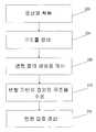
도 11은 변형 맵 상에 제약을 위치시키는 방법의 흐름도를 도시하고 있다. 의료인은 환자(14)의 적어도 일부분에 대한 하나 이상의 영상(예컨대, 계획 영상)의 획득을 개시한다(200). 다음으로, 의료인은 하나 이상의 윤곽 또는 다른 식별 툴을 이용하여 환자(14)의 하나 이상의 영상에서 하나 이상의 구조를 식별하거나 규정한다(204). 정의된 구조는 통상적으로 하나 이상의 영상 내의 표적(38)이 된다. 의료인은 이전에 획득된 영상 중 2개 이상의 영상 간의 변형 맵을 변형 모듈(114)에 의해 생성하여, 하나의 영상으로부터의 정의된 구조를 다른 영상에 관련시켜 변형 기반의 정의된 구조를 생성한다(208). 의료인은 변형 기반의 정의된 구조를 수정하고(212), 수정된 변형 기반의 정의된 구조에 기초하여 변형 맵을 갱신하기 위해 변형 모듈(114)을 개시한다(216).11 shows a flowchart of a method for placing a constraint on a deformation map. The practitioner initiates 200 acquisition of one or more images (eg, planned images) of at least a portion of the
도 12는 변형 맵 상에 제약을 위치시키는 방법의 흐름도를 도시하고 있다. 의료인은 환자(14)의 적어도 일부분에 대한 하나 이상의 영상(예컨대, 계획 영상)의 획득을 개시한다(250). 다음으로, 의료인은 하나 이상의 윤곽 또는 다른 식별 툴을 이용하여 환자(14)의 하나 이상의 영상에서 하나 이상의 구조를 식별하거나 규정한다(254). 정의된 구조는 통상적으로 하나 이상의 영상 내의 표적(38)이 된다. 의료인은 이전에 획득된 영상 중 2개 이상의 영상 간의 변형 맵을 변형 모듈(114)에 의해 생성하여, 하나의 영상으로부터의 정의된 구조를 다른 영상에 관련시켜 변형 기반의 정의된 구조를 생성한다(258). 의료인은 변형 기반의 정의된 구조를 수정하고(262), 수정된 변형 기반의 정의된 구조에 기초하여 변형 맵을 갱신하기 위해 변형 모듈(114)을 개시한다(266). 갱신된 변형 맵에 기초하여, 윤곽 모 듈(118)은 영상들 중의 하나에 윤곽을 생성한다(270).12 shows a flowchart of a method for placing a constraint on a deformation map. The practitioner initiates 250 acquisition of one or more images (eg, planned images) of at least a portion of the
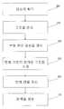
도 13은 변형 맵 상에 제약을 위치시키는 방법의 흐름도를 도시하고 있다. 의료인은 환자(14)의 적어도 일부분에 대한 하나 이상의 영상(예컨대, 계획 영상)의 획득을 개시한다(300). 다음으로, 의료인은 제1 윤곽 세트 또는 다른 식별 툴을 이용하여 환자(14)의 하나 이상의 영상에서 하나 이상의 구조를 식별하거나 규정한다(304). 정의된 구조는 통상적으로 하나 이상의 영상 내의 표적(38)이 된다. 의료인은 제2 윤곽 세트 또는 다른 식별 툴을 이용하여 환자(14)의 하나 이상의 영상에서 하나 이상의 구조를 식별, 규정 또는 추가 규정한다(308). 의료인은 윤곽 세트 간의 차이를 식별하기 위해 제1 윤곽 세트 및 제2 윤곽 세트 간의 변형 맵의 생성을 개시한다(312).13 shows a flowchart of a method for placing a constraint on a deformation map. The practitioner initiates 300 an acquisition of one or more images (eg, planned images) of at least a portion of the
본 발명의 다양한 특징 및 장점은 이하의 청구범위에 의해 정해진다.Various features and advantages of the invention are defined by the following claims.
Claims (31)
Translated fromKoreanApplications Claiming Priority (3)
| Application Number | Priority Date | Filing Date | Title |
|---|---|---|---|
| US70158005P | 2005-07-22 | 2005-07-22 | |
| US60/701,580 | 2005-07-22 | ||
| PCT/US2006/028536WO2007014092A2 (en) | 2005-07-22 | 2006-07-21 | Method of placing constraints on a deformation map and system for implementing same |
Publications (1)
| Publication Number | Publication Date |
|---|---|
| KR20080044251Atrue KR20080044251A (en) | 2008-05-20 |
Family
ID=37683851
Family Applications (1)
| Application Number | Title | Priority Date | Filing Date |
|---|---|---|---|
| KR1020087004293ACeasedKR20080044251A (en) | 2005-07-22 | 2006-07-21 | How to place a constraint on a deformation map and system implementing the method |
Country Status (7)
| Country | Link |
|---|---|
| US (1) | US7567694B2 (en) |
| EP (1) | EP1907058B1 (en) |
| JP (1) | JP2009507524A (en) |
| KR (1) | KR20080044251A (en) |
| CN (1) | CN101529442A (en) |
| CA (1) | CA2616299A1 (en) |
| WO (1) | WO2007014092A2 (en) |
Families Citing this family (82)
| Publication number | Priority date | Publication date | Assignee | Title |
|---|---|---|---|---|
| EP1790203B1 (en) | 2004-07-21 | 2015-12-30 | Mevion Medical Systems, Inc. | A programmable radio frequency waveform generator for a synchrocyclotron |
| US7957507B2 (en) | 2005-02-28 | 2011-06-07 | Cadman Patrick F | Method and apparatus for modulating a radiation beam |
| US8232535B2 (en) | 2005-05-10 | 2012-07-31 | Tomotherapy Incorporated | System and method of treating a patient with radiation therapy |
| WO2007014104A2 (en) | 2005-07-22 | 2007-02-01 | Tomotherapy Incorporated | System and method of evaluating dose delivered by a radiation therapy system |
| CN101512547A (en) | 2005-07-22 | 2009-08-19 | 断层放疗公司 | Method of and system for predicting dose delivery |
| WO2007014105A2 (en) | 2005-07-22 | 2007-02-01 | Tomotherapy Incorporated | Method and system for adapting a radiation therapy treatment plan based on a biological model |
| CA2616296A1 (en) | 2005-07-22 | 2007-02-01 | Tomotherapy Incorporated | System and method of generating contour structures using a dose volume histogram |
| KR20080044251A (en) | 2005-07-22 | 2008-05-20 | 토모테라피 인코포레이티드 | How to place a constraint on a deformation map and system implementing the method |
| CN101267857A (en) | 2005-07-22 | 2008-09-17 | 断层放疗公司 | System and method of delivering radiation therapy to a moving region of interest |
| KR20080049716A (en) | 2005-07-22 | 2008-06-04 | 토모테라피 인코포레이티드 | Methods and systems for evaluating quality assurance criteria associated with delivery of treatment plans |
| JP2009502250A (en) | 2005-07-22 | 2009-01-29 | トモセラピー・インコーポレーテッド | Method and system for processing data associated with radiation therapy treatment planning |
| AU2006272746A1 (en) | 2005-07-22 | 2007-02-01 | Tomotherapy Incorporated | Method and system for evaluating delivered dose |
| US8442287B2 (en) | 2005-07-22 | 2013-05-14 | Tomotherapy Incorporated | Method and system for evaluating quality assurance criteria in delivery of a treatment plan |
| JP5060476B2 (en) | 2005-07-22 | 2012-10-31 | トモセラピー・インコーポレーテッド | System and method for detecting respiratory phase of a patient undergoing radiation therapy |
| US9731148B2 (en) | 2005-07-23 | 2017-08-15 | Tomotherapy Incorporated | Radiation therapy imaging and delivery utilizing coordinated motion of gantry and couch |
| EP1934898A4 (en)* | 2005-10-14 | 2009-10-21 | Tomotherapy Inc | Method and interface for adaptive radiation therapy |
| CA2626536C (en) | 2005-10-17 | 2016-04-26 | Alberta Cancer Board | Real-time dose reconstruction using dynamic simulation and image guided adaptive radiotherapy |
| ATE538841T1 (en) | 2005-10-17 | 2012-01-15 | Alberta Health Services | INTEGRATED EXTERNAL BEAM RADIOTHERAPY AND MRI SYSTEM |
| EP2389977A3 (en) | 2005-11-18 | 2012-01-25 | Still River Systems, Inc. | Charged particle radiation therapy |
| DE102005058871B3 (en)* | 2005-12-09 | 2007-07-26 | Siemens Ag | Medical irradiation device for treating tumor of patient, has data processing device that is data technically equipped in such a manner that characteristics of radiation are visualizable in common representation |
| US7711087B2 (en)* | 2006-04-07 | 2010-05-04 | Varian Medical Systems, Inc. | Patient setup using tomosynthesis techniques |
| US7869637B2 (en)* | 2006-07-31 | 2011-01-11 | Siemens Medical Solutions Usa, Inc. | Histogram calculation for auto-windowing of collimated X-ray image |
| US7777742B2 (en)* | 2006-08-21 | 2010-08-17 | Siemens Medical Solutions Usa, Inc. | Systems and methods of non-rigid volume registration |
| CN101820827A (en) | 2007-10-25 | 2010-09-01 | 断层放疗公司 | The method of the fractionation of radiation dosage of accommodation radiotherapy dosage |
| US8581523B2 (en) | 2007-11-30 | 2013-11-12 | Mevion Medical Systems, Inc. | Interrupted particle source |
| US8933650B2 (en) | 2007-11-30 | 2015-01-13 | Mevion Medical Systems, Inc. | Matching a resonant frequency of a resonant cavity to a frequency of an input voltage |
| US20090159682A1 (en) | 2007-12-24 | 2009-06-25 | Dynamics Inc. | Cards and devices with multi-function magnetic emulators and methods for using same |
| US20090282131A1 (en)* | 2008-05-09 | 2009-11-12 | Michael Maschke | Medical system architecture |
| US8803910B2 (en) | 2008-08-28 | 2014-08-12 | Tomotherapy Incorporated | System and method of contouring a target area |
| DE102009006147A1 (en)* | 2008-12-23 | 2010-06-24 | Siemens Aktiengesellschaft | Model generator for cardiological diseases |
| JP5355074B2 (en)* | 2008-12-26 | 2013-11-27 | キヤノン株式会社 | 3D shape data processing apparatus, 3D shape data processing method and program |
| US20110019889A1 (en)* | 2009-06-17 | 2011-01-27 | David Thomas Gering | System and method of applying anatomically-constrained deformation |
| WO2011005329A2 (en)* | 2009-07-09 | 2011-01-13 | The Board Of Trustees Of The Leland Stanford Junior University | Method and system for real-time dmlc-based target tracking with optimal motion compensating leaf adaptation |
| US8934605B2 (en) | 2010-02-24 | 2015-01-13 | Accuray Incorporated | Gantry image guided radiotherapy system and related treatment delivery methods |
| WO2011156526A2 (en) | 2010-06-08 | 2011-12-15 | Accuray, Inc. | Imaging methods and target tracking for image-guided radiation treatment |
| CN103079467B (en)* | 2010-06-23 | 2016-06-29 | 瓦里安医疗系统国际股份公司 | Mechanisms for advanced structure generation and editing |
| US9401051B2 (en)* | 2010-06-23 | 2016-07-26 | Varian Medical Systems International Ag | Mechanism for dynamically propagating real-time alterations of medical images |
| US10311585B2 (en)* | 2010-06-23 | 2019-06-04 | Varian Medical Systems International Ag | Mechanism for advanced structure generation and editing |
| WO2012069965A1 (en)* | 2010-11-23 | 2012-05-31 | Koninklijke Philips Electronics N.V. | Interactive deformation map corrections |
| US10152951B2 (en) | 2011-02-28 | 2018-12-11 | Varian Medical Systems International Ag | Method and system for interactive control of window/level parameters of multi-image displays |
| JP5611091B2 (en)* | 2011-03-18 | 2014-10-22 | 三菱重工業株式会社 | Radiotherapy apparatus control apparatus, processing method thereof, and program |
| US9074848B1 (en)* | 2011-04-13 | 2015-07-07 | Litel Instruments | Precision geographic location system and method utilizing an image product |
| CN103782320B (en)* | 2011-08-30 | 2017-03-15 | 皇家飞利浦有限公司 | In deformable image registration workflow, the correction of user input and deformation vector field is integrated |
| US9314160B2 (en)* | 2011-12-01 | 2016-04-19 | Varian Medical Systems, Inc. | Systems and methods for real-time target validation for image-guided radiation therapy |
| US9047701B2 (en)* | 2012-03-31 | 2015-06-02 | Varian Medical Systems, Inc. | 4D cone beam CT using deformable registration |
| JP6523957B2 (en) | 2012-09-28 | 2019-06-05 | メビオン・メディカル・システムズ・インコーポレーテッド | Magnetic shim for changing the magnetic field |
| TW201424467A (en) | 2012-09-28 | 2014-06-16 | Mevion Medical Systems Inc | Controlling intensity of a particle beam |
| EP2901822B1 (en) | 2012-09-28 | 2020-04-08 | Mevion Medical Systems, Inc. | Focusing a particle beam |
| TW201422278A (en) | 2012-09-28 | 2014-06-16 | Mevion Medical Systems Inc | Control system for a particle accelerator |
| JP6254600B2 (en) | 2012-09-28 | 2017-12-27 | メビオン・メディカル・システムズ・インコーポレーテッド | Particle accelerator |
| TW201438787A (en) | 2012-09-28 | 2014-10-16 | Mevion Medical Systems Inc | Controlling particle therapy |
| WO2014052719A2 (en) | 2012-09-28 | 2014-04-03 | Mevion Medical Systems, Inc. | Adjusting energy of a particle beam |
| CN108770178B (en) | 2012-09-28 | 2021-04-16 | 迈胜医疗设备有限公司 | Magnetic field regenerator |
| US10254739B2 (en) | 2012-09-28 | 2019-04-09 | Mevion Medical Systems, Inc. | Coil positioning system |
| US10137315B2 (en) | 2012-10-26 | 2018-11-27 | Brainlab Ag | Determining an irradiation region for radiotherapy based on model patient data and patient image data |
| EP2912585B1 (en)* | 2012-10-29 | 2019-06-19 | Koninklijke Philips N.V. | Automatic optimal imrt/vmat treatment plan generation. |
| WO2014108174A1 (en) | 2013-01-09 | 2014-07-17 | Brainlab Ag | Cbct and x-ray combined setup with x-ray verification of patient positioning |
| EP2962309B1 (en) | 2013-02-26 | 2022-02-16 | Accuray, Inc. | Electromagnetically actuated multi-leaf collimator |
| US8791656B1 (en) | 2013-05-31 | 2014-07-29 | Mevion Medical Systems, Inc. | Active return system |
| US9730308B2 (en) | 2013-06-12 | 2017-08-08 | Mevion Medical Systems, Inc. | Particle accelerator that produces charged particles having variable energies |
| CN105764567B (en) | 2013-09-27 | 2019-08-09 | 梅维昂医疗系统股份有限公司 | Particle beam scanning |
| US9962560B2 (en) | 2013-12-20 | 2018-05-08 | Mevion Medical Systems, Inc. | Collimator and energy degrader |
| US10675487B2 (en) | 2013-12-20 | 2020-06-09 | Mevion Medical Systems, Inc. | Energy degrader enabling high-speed energy switching |
| US9661736B2 (en) | 2014-02-20 | 2017-05-23 | Mevion Medical Systems, Inc. | Scanning system for a particle therapy system |
| US9626808B2 (en)* | 2014-08-01 | 2017-04-18 | Electronic Arts Inc. | Image-based deformation of simulated characters of varied topology |
| US9950194B2 (en) | 2014-09-09 | 2018-04-24 | Mevion Medical Systems, Inc. | Patient positioning system |
| US10252081B2 (en)* | 2015-09-25 | 2019-04-09 | Varian Medical Systems International Ag | Apparatus and method using automatic generation of a base dose |
| US10786689B2 (en) | 2015-11-10 | 2020-09-29 | Mevion Medical Systems, Inc. | Adaptive aperture |
| EP3181049B1 (en)* | 2015-12-18 | 2018-02-14 | RaySearch Laboratories AB | Radiotherapy method, computer program and computer system |
| US10062168B2 (en) | 2016-02-26 | 2018-08-28 | Varian Medical Systems International Ag | 5D cone beam CT using deformable registration |
| WO2018009779A1 (en) | 2016-07-08 | 2018-01-11 | Mevion Medical Systems, Inc. | Treatment planning |
| EP3496814B1 (en)* | 2016-08-11 | 2021-03-10 | Koninklijke Philips N.V. | Medical product configured to be used for image based radiotherapy planning |
| US11103730B2 (en) | 2017-02-23 | 2021-08-31 | Mevion Medical Systems, Inc. | Automated treatment in particle therapy |
| US11058892B2 (en) | 2017-05-05 | 2021-07-13 | Zap Surgical Systems, Inc. | Revolving radiation collimator |
| CN111093767B (en) | 2017-06-30 | 2022-08-23 | 美国迈胜医疗系统有限公司 | Configurable collimator controlled using linear motors |
| CN108401421B (en) | 2017-09-06 | 2022-12-20 | 睿谱外科系统股份有限公司 | Self-shielding integrated control radiosurgery system |
| EP3542859A1 (en)* | 2018-03-20 | 2019-09-25 | Koninklijke Philips N.V. | Determining a medical imaging schedule |
| US10918885B2 (en) | 2018-09-27 | 2021-02-16 | Varian Medical Systems International Ag | Systems, methods and devices for automated target volume generation |
| US11684446B2 (en) | 2019-02-27 | 2023-06-27 | Zap Surgical Systems, Inc. | Device for radiosurgical treatment of uterine fibroids |
| CN113811356B (en) | 2019-03-08 | 2025-01-03 | 美国迈胜医疗系统有限公司 | Collimators and range adjusters for particle therapy systems |
| JP7432437B2 (en)* | 2020-04-28 | 2024-02-16 | キヤノンメディカルシステムズ株式会社 | Treatment support devices and treatment support programs |
| JP2024506842A (en) | 2021-02-01 | 2024-02-15 | ザップ サージカル システムズ, インコーポレイテッド | Reverse planning device and method for radiotherapy |
Family Cites Families (299)
| Publication number | Priority date | Publication date | Assignee | Title |
|---|---|---|---|---|
| DE2302938C3 (en) | 1973-01-22 | 1979-07-12 | Polymer-Physik Gmbh & Co Kg, 2844 Lemfoerde | Multi-stage accelerator for charged particles with high vacuum insulation |
| US3964467A (en) | 1973-01-30 | 1976-06-22 | Bio Response Inc. | Methods and apparatus for augmentation of the production of anti-bodies in animals and humans and the collection thereof |
| US4189470A (en) | 1973-01-30 | 1980-02-19 | Bio-Response, Inc. | Method for the continuous removal of a specific antibody from the lymph fluid in animals and humans |
| CA990404A (en) | 1974-08-01 | 1976-06-01 | Stanley O. Schriber | Double pass linear accelerator operating in a standing wave mode |
| GB1503517A (en) | 1974-09-10 | 1978-03-15 | Science Res Council | Electrostatic accelerators |
| US4208185A (en) | 1976-08-16 | 1980-06-17 | Mitsubishi Chemical Industries Limited | Method and apparatus for the measurement of antigens and antibodies |
| US4149081A (en) | 1976-11-29 | 1979-04-10 | Varian Associates, Inc. | Removal of spectral artifacts and utilization of spectral effects in computerized tomography |
| FR2390069B1 (en) | 1977-05-05 | 1981-04-30 | Commissariat Energie Atomique | |
| DE2804393C2 (en) | 1978-02-02 | 1987-01-02 | Jens Prof. Dr. 8520 Buckenhof Christiansen | Method for generating and accelerating electrons or ions in a discharge vessel, as well as associated particle accelerator and further associated applications of the method |
| US4273867A (en) | 1979-04-05 | 1981-06-16 | Mallinckrodt, Inc. | Method and reagent for counteracting lipemic interference |
| US4395631A (en) | 1979-10-16 | 1983-07-26 | Occidental Research Corporation | High density ion source |
| US4314180A (en) | 1979-10-16 | 1982-02-02 | Occidental Research Corporation | High density ion source |
| US4426582A (en) | 1980-01-21 | 1984-01-17 | Oregon Graduate Center | Charged particle beam apparatus and method utilizing liquid metal field ionization source and asymmetric three element lens system |
| US4393334A (en) | 1981-02-09 | 1983-07-12 | David Glaser | Electron acceleration in ionizable gas |
| US4388560A (en) | 1981-05-26 | 1983-06-14 | Hughes Aircraft Company | Filament dispenser cathode |
| US4401765A (en) | 1981-09-01 | 1983-08-30 | E. I. Du Pont De Nemours And Company | Covalently bonded high refractive index particle reagents and their use in light scattering immunoassays |
| US4480042A (en) | 1981-10-28 | 1984-10-30 | E. I. Du Pont De Nemours And Company | Covalently bonded high refractive index particle reagents and their use in light scattering immunoassays |
| US4446403A (en) | 1982-05-26 | 1984-05-01 | International Business Machines Corporation | Compact plug connectable ion source |
| US4570103A (en) | 1982-09-30 | 1986-02-11 | Schoen Neil C | Particle beam accelerators |
| NL8400845A (en) | 1984-03-16 | 1985-10-16 | Optische Ind De Oude Delft Nv | DEVICE FOR GAP RADIOGRAPHY. |
| US4703018A (en) | 1985-02-20 | 1987-10-27 | E. I. Du Pont De Nemours And Company | High refractive index haloalkyl-functional shell-core polymers and their use in light scattering immunoassays |
| US4752692A (en) | 1985-04-26 | 1988-06-21 | Hughes Aircraft Company | Liquid metal ion source |
| US4815446A (en) | 1985-05-09 | 1989-03-28 | Alpha Therapeutic Corporation | Process for treating metastasis of cancerous tumors |
| US4664869A (en) | 1985-07-01 | 1987-05-12 | The United States Of America As Represented By The United States Department Of Energy | Method for the simultaneous preparation of Radon-211, Xenon-125, Xenon-123, Astatine-211, Iodine-125 and Iodine-123 |
| US4868843A (en) | 1986-09-10 | 1989-09-19 | Varian Associates, Inc. | Multileaf collimator and compensator for radiotherapy machines |
| US4736106A (en) | 1986-10-08 | 1988-04-05 | Michigan State University | Method and apparatus for uniform charged particle irradiation of a surface |
| JPS63122923A (en) | 1986-11-13 | 1988-05-26 | Agency Of Ind Science & Technol | Ultrasonic thermometric apparatus |
| US4912731A (en) | 1987-04-13 | 1990-03-27 | Vittorio Nardi | Plasma focus apparatus with field distortion elements |
| US4818914A (en) | 1987-07-17 | 1989-04-04 | Sri International | High efficiency lamp |
| US4879518A (en) | 1987-10-13 | 1989-11-07 | Sysmed, Inc. | Linear particle accelerator with seal structure between electrodes and insulators |
| US4870287A (en) | 1988-03-03 | 1989-09-26 | Loma Linda University Medical Center | Multi-station proton beam therapy system |
| US5073913A (en) | 1988-04-26 | 1991-12-17 | Acctek Associates, Inc. | Apparatus for acceleration and application of negative ions and electrons |
| JPH01299537A (en) | 1988-05-27 | 1989-12-04 | Agency Of Ind Science & Technol | Acoustic characteristic and temperature measuring method and its device |
| US5250388A (en) | 1988-05-31 | 1993-10-05 | Westinghouse Electric Corp. | Production of highly conductive polymers for electronic circuits |
| US5124658A (en) | 1988-06-13 | 1992-06-23 | Adler Richard J | Nested high voltage generator/particle accelerator |
| JPH078300B2 (en) | 1988-06-21 | 1995-02-01 | 三菱電機株式会社 | Charged particle beam irradiation device |
| EP0371303B1 (en) | 1988-11-29 | 1994-04-27 | Varian International AG. | Radiation therapy apparatus |
| US4998268A (en) | 1989-02-09 | 1991-03-05 | James Winter | Apparatus and method for therapeutically irradiating a chosen area using a diagnostic computer tomography scanner |
| US5003998A (en) | 1989-04-21 | 1991-04-02 | Collett Donald H | Method and apparatus for cleaning and sanitizing HVAC systems |
| US5008907A (en) | 1989-05-31 | 1991-04-16 | The Regents Of The University Of California | Therapy x-ray scanner |
| JP2515022B2 (en) | 1989-08-22 | 1996-07-10 | 株式会社東芝 | Accelerator controller |
| US5065315A (en) | 1989-10-24 | 1991-11-12 | Garcia Angela M | System and method for scheduling and reporting patient related services including prioritizing services |
| US5474911A (en) | 1989-12-01 | 1995-12-12 | The Board Of Trustees Of Leland Stanford Jr. University | Promotion of high specificity molecular assembly |
| ES2079467T3 (en) | 1989-12-19 | 1996-01-16 | Ciba Geigy Ag | PROCEDURE AND DEVICE FOR THE GENETIC TRANSFORMATION OF CELLS. |
| US5346548A (en) | 1990-06-25 | 1994-09-13 | The Regents Of The University Of California | Highly durable cement products containing siliceous ashes |
| EP0489904B1 (en) | 1990-07-02 | 1998-03-04 | Varian Associates, Inc. | Radiation therapy x-ray simulator |
| US5084682A (en) | 1990-09-07 | 1992-01-28 | Science Applications International Corporation | Close-coupled RF power systems for linacs |
| US6405072B1 (en) | 1991-01-28 | 2002-06-11 | Sherwood Services Ag | Apparatus and method for determining a location of an anatomical target with reference to a medical apparatus |
| US5210414A (en) | 1991-03-29 | 1993-05-11 | The United States Of America As Represented By The Department Of Health And Human Services | Differential surface composition analysis by multiple-voltage electron beam X-ray spectroscopy |
| US5596653A (en) | 1991-04-09 | 1997-01-21 | Mitsubishi Denki Kabushiki Kaisha | Radiation therapy treatment planning system |
| US5317616A (en) | 1992-03-19 | 1994-05-31 | Wisconsin Alumni Research Foundation | Method and apparatus for radiation therapy |
| US5661773A (en) | 1992-03-19 | 1997-08-26 | Wisconsin Alumni Research Foundation | Interface for radiation therapy machine |
| US5351280A (en) | 1992-03-19 | 1994-09-27 | Wisconsin Alumni Research Foundation | Multi-leaf radiation attenuator for radiation therapy |
| US5335255A (en) | 1992-03-24 | 1994-08-02 | Seppi Edward J | X-ray scanner with a source emitting plurality of fan beams |
| US5382914A (en) | 1992-05-05 | 1995-01-17 | Accsys Technology, Inc. | Proton-beam therapy linac |
| US5453310A (en) | 1992-08-11 | 1995-09-26 | E. Khashoggi Industries | Cementitious materials for use in packaging containers and their methods of manufacture |
| US5641584A (en) | 1992-08-11 | 1997-06-24 | E. Khashoggi Industries | Highly insulative cementitious matrices and methods for their manufacture |
| US5580624A (en) | 1992-08-11 | 1996-12-03 | E. Khashoggi Industries | Food and beverage containers made from inorganic aggregates and polysaccharide, protein, or synthetic organic binders, and the methods of manufacturing such containers |
| US5596619A (en) | 1992-08-21 | 1997-01-21 | Nomos Corporation | Method and apparatus for conformal radiation therapy |
| US5391139A (en) | 1992-09-03 | 1995-02-21 | William Beaumont Hospital | Real time radiation treatment planning system |
| US5405309A (en) | 1993-04-28 | 1995-04-11 | Theragenics Corporation | X-ray emitting interstitial implants |
| US5877192A (en) | 1993-05-28 | 1999-03-02 | Astra Aktiebolag | Method for the treatment of gastric acid-related diseases and production of medication using (-) enantiomer of omeprazole |
| EP0810005B1 (en) | 1993-06-09 | 2000-09-27 | Wisconsin Alumni Research Foundation | Radiation therapy system |
| DE69416587T2 (en) | 1993-06-09 | 1999-07-15 | Wisconsin Alumni Research Foundation, Madison, Wis. | RADIATION THERAPY MACHINE FOR GENERATING A DESIRED INTENSITY PROFILE |
| WO1995001448A1 (en) | 1993-06-30 | 1995-01-12 | Dcv Biologics L.P. | A method for introducing a biological substance into a target |
| US5576602A (en) | 1993-08-18 | 1996-11-19 | Hitachi, Ltd. | Method for extracting charged particle beam and small-sized accelerator for charged particle beam |
| US5483122A (en) | 1994-02-18 | 1996-01-09 | Regents Of The University Of Michigan | Two-beam particle acceleration method and apparatus |
| EP0673661B1 (en) | 1994-03-25 | 2003-03-12 | Kabushiki Kaisha Toshiba | Radiotherapy system |
| US5537452A (en) | 1994-05-10 | 1996-07-16 | Shepherd; Joseph S. | Radiation therapy and radiation surgery treatment system and methods of use of same |
| FI942686A0 (en) | 1994-06-07 | 1994-06-07 | Alko Ab Oy | Composition of the starch acetate with a variety of compounds, for the production and distribution |
| US5528651A (en) | 1994-06-09 | 1996-06-18 | Elekta Instrument Ab | Positioning device and method for radiation treatment |
| US5836905A (en) | 1994-06-20 | 1998-11-17 | Lemelson; Jerome H. | Apparatus and methods for gene therapy |
| AU2866695A (en) | 1994-07-08 | 1996-02-09 | New England Medical Center Hospitals, Inc., The | E6 binding proteins |
| US5578909A (en) | 1994-07-15 | 1996-11-26 | The Regents Of The Univ. Of California | Coupled-cavity drift-tube linac |
| US6417178B1 (en) | 1994-07-19 | 2002-07-09 | University Of Pittsburgh | Amyloid binding nitrogen-linked compounds for the antemortem diagnosis of alzheimer's disease, in vivo imaging and prevention of amyloid deposits |
| US5627041A (en) | 1994-09-02 | 1997-05-06 | Biometric Imaging, Inc. | Disposable cartridge for an assay of a biological sample |
| US5622187A (en) | 1994-09-30 | 1997-04-22 | Nomos Corporation | Method and apparatus for patient positioning for radiation therapy |
| US5471516A (en) | 1994-10-06 | 1995-11-28 | Varian Associates, Inc. | Radiotherapy apparatus equipped with low dose localizing and portal imaging X-ray source |
| US5489780A (en) | 1994-11-02 | 1996-02-06 | Diamondis; Peter J. | Radon gas measurement apparatus having alpha particle-detecting photovoltaic photodiode surrounded by porous pressed metal daughter filter electrically charged as PO-218 ion accelerator |
| US5661377A (en) | 1995-02-17 | 1997-08-26 | Intraop Medical, Inc. | Microwave power control apparatus for linear accelerator using hybrid junctions |
| US6500343B2 (en) | 1995-02-21 | 2002-12-31 | Iqbal W. Siddiqi | Method for mixing and separation employing magnetic particles |
| US5523578A (en) | 1995-03-22 | 1996-06-04 | Herskovic; Arnold | Electromagnetic radiation shielding arrangement and method for radiation therapy patients |
| ATE226842T1 (en) | 1995-04-18 | 2002-11-15 | Univ Loma Linda Med | SYSTEM FOR MULTIPLE PARTICLE THERAPY |
| US5842175A (en) | 1995-04-28 | 1998-11-24 | Therassist Software, Inc. | Therapy system |
| US5668371A (en) | 1995-06-06 | 1997-09-16 | Wisconsin Alumni Research Foundation | Method and apparatus for proton therapy |
| US6345114B1 (en) | 1995-06-14 | 2002-02-05 | Wisconsin Alumni Research Foundation | Method and apparatus for calibration of radiation therapy equipment and verification of radiation treatment |
| US5621779A (en) | 1995-07-20 | 1997-04-15 | Siemens Medical Systems, Inc. | Apparatus and method for delivering radiation to an object and for displaying delivered radiation |
| US5591983A (en) | 1995-06-30 | 1997-01-07 | Siemens Medical Systems, Inc. | Multiple layer multileaf collimator |
| US5754622A (en) | 1995-07-20 | 1998-05-19 | Siemens Medical Systems, Inc. | System and method for verifying the amount of radiation delivered to an object |
| US5581156A (en) | 1995-07-31 | 1996-12-03 | The United States Of America As Represented By The Secretary Of The Army | HF sustained, DC discharge driven negative ion source with automatic control system |
| US6011825A (en) | 1995-08-09 | 2000-01-04 | Washington University | Production of 64 Cu and other radionuclides using a charged-particle accelerator |
| GB9520564D0 (en) | 1995-10-07 | 1995-12-13 | Philips Electronics Nv | Apparatus for treating a patient |
| SE505513C2 (en) | 1995-11-14 | 1997-09-08 | Elekta Ab | Device for repositioning a patient |
| US20010055812A1 (en) | 1995-12-05 | 2001-12-27 | Alec Mian | Devices and method for using centripetal acceleration to drive fluid movement in a microfluidics system with on-board informatics |
| US5647663A (en) | 1996-01-05 | 1997-07-15 | Wisconsin Alumni Research Foundation | Radiation treatment planning method and apparatus |
| US5721123A (en) | 1996-01-05 | 1998-02-24 | Microfab Technology, Inc. | Methods and apparatus for direct heating of biological material |
| JP3472657B2 (en) | 1996-01-18 | 2003-12-02 | 三菱電機株式会社 | Particle beam irradiation equipment |
| CA2195697A1 (en) | 1996-02-02 | 1997-08-03 | Masahumi Kitano | Novel substituted guanidine derivatives, process for production thereof, and pharmaceutical uses thereof |
| US5818902A (en) | 1996-03-01 | 1998-10-06 | Elekta Ab | Intensity modulated arc therapy with dynamic multi-leaf collimation |
| US5760395A (en) | 1996-04-18 | 1998-06-02 | Universities Research Assoc., Inc. | Method and apparatus for laser-controlled proton beam radiology |
| US5673300A (en) | 1996-06-11 | 1997-09-30 | Wisconsin Alumni Research Foundation | Method of registering a radiation treatment plan to a patient |
| US5734168A (en) | 1996-06-20 | 1998-03-31 | Siemens Medical Systems, Inc. | Monolithic structure with internal cooling for medical linac |
| US5811944A (en) | 1996-06-25 | 1998-09-22 | The United States Of America As Represented By The Department Of Energy | Enhanced dielectric-wall linear accelerator |
| US5821705A (en) | 1996-06-25 | 1998-10-13 | The United States Of America As Represented By The United States Department Of Energy | Dielectric-wall linear accelerator with a high voltage fast rise time switch that includes a pair of electrodes between which are laminated alternating layers of isolated conductors and insulators |
| US6331194B1 (en) | 1996-06-25 | 2001-12-18 | The United States Of America As Represented By The United States Department Of Energy | Process for manufacturing hollow fused-silica insulator cylinder |
| US5695443A (en) | 1996-07-26 | 1997-12-09 | Brent; Robert W. | High energy radiation emission shelter and method of making the same |
| US5712482A (en) | 1996-08-05 | 1998-01-27 | Physics Technology, Inc. | Portable electronic radiographic imaging apparatus |
| JP3690882B2 (en) | 1996-08-16 | 2005-08-31 | 富士写真フイルム株式会社 | Image enhancement processing method and apparatus |
| US5820553A (en) | 1996-08-16 | 1998-10-13 | Siemens Medical Systems, Inc. | Identification system and method for radiation therapy |
| EP0826394B1 (en) | 1996-08-30 | 2004-05-19 | Hitachi, Ltd. | Charged particle beam apparatus |
| DE69634602T2 (en) | 1996-09-19 | 2006-02-09 | High Voltage Engineering Europa B.V. | Manufacturing method of an accelerator tube |
| EP0833549B1 (en) | 1996-09-25 | 2004-11-24 | High Voltage Engineering Europa B.V. | Particle accelerator with vacuum pump connected to the low voltage side |
| GB9620296D0 (en) | 1996-09-28 | 1996-11-13 | Carton Edge Ltd | Apparatus for mounting a cutting strip |
| DE69737508T2 (en) | 1996-10-24 | 2007-11-29 | The Nomos Corp. | PLANNING AND DEVICE FOR PLANTING THE IRRADIATION DOSING |
| US5920601A (en) | 1996-10-25 | 1999-07-06 | Lockheed Martin Idaho Technologies Company | System and method for delivery of neutron beams for medical therapy |
| US6200959B1 (en) | 1996-12-04 | 2001-03-13 | Powerject Vaccines Inc. | Genetic induction of anti-viral immune response and genetic vaccine for filovirus |
| US5870447A (en) | 1996-12-30 | 1999-02-09 | Brookhaven Science Associates | Method and apparatus for generating low energy nuclear particles |
| US5962995A (en) | 1997-01-02 | 1999-10-05 | Applied Advanced Technologies, Inc. | Electron beam accelerator |
| US5729028A (en) | 1997-01-27 | 1998-03-17 | Rose; Peter H. | Ion accelerator for use in ion implanter |
| WO1998035358A1 (en) | 1997-02-06 | 1998-08-13 | The University Of Miami | Iso-energetic intensity modulator for therapeutic electron beams, electron beam wedge and flattening filters |
| JP3178381B2 (en) | 1997-02-07 | 2001-06-18 | 株式会社日立製作所 | Charged particle irradiation device |
| CN1230865C (en) | 1997-03-14 | 2005-12-07 | 佳能株式会社 | imaging device |
| US6029079A (en) | 1997-05-22 | 2000-02-22 | Regents Of The University Of California | Evaluated teletherapy source library |
| JP4212128B2 (en) | 1997-07-02 | 2009-01-21 | 株式会社東芝 | Radiation therapy equipment |
| US6071748A (en) | 1997-07-16 | 2000-06-06 | Ljl Biosystems, Inc. | Light detection device |
| US6094760A (en) | 1997-08-04 | 2000-08-01 | Sumitomo Heavy Industries, Ltd. | Bed system for radiation therapy |
| US5963615A (en) | 1997-08-08 | 1999-10-05 | Siemens Medical Systems, Inc. | Rotational flatness improvement |
| US6218675B1 (en) | 1997-08-28 | 2001-04-17 | Hitachi, Ltd. | Charged particle beam irradiation apparatus |
| US6636622B2 (en) | 1997-10-15 | 2003-10-21 | Wisconsin Alumni Research Foundation | Method and apparatus for calibration of radiation therapy equipment and verification of radiation treatment |
| US6129670A (en) | 1997-11-24 | 2000-10-10 | Burdette Medical Systems | Real time brachytherapy spatial registration and visualization system |
| US6198957B1 (en) | 1997-12-19 | 2001-03-06 | Varian, Inc. | Radiotherapy machine including magnetic resonance imaging system |
| US6475994B2 (en) | 1998-01-07 | 2002-11-05 | Donald A. Tomalia | Method and articles for transfection of genetic material |
| US6360116B1 (en) | 1998-02-27 | 2002-03-19 | Varian Medical Systems, Inc. | Brachytherapy system for prostate cancer treatment with computer implemented systems and processes to facilitate pre-operative planning and post-operative evaluations |
| JPH11253563A (en) | 1998-03-10 | 1999-09-21 | Hitachi Ltd | Charged particle beam irradiation method and apparatus |
| US6020135A (en) | 1998-03-27 | 2000-02-01 | Affymetrix, Inc. | P53-regulated genes |
| US6020538A (en) | 1998-05-01 | 2000-02-01 | Korea Kumho Petrochemical Co., Ltd. | Genetic transformation of orchids |
| US6393096B1 (en) | 1998-05-27 | 2002-05-21 | Nomos Corporation | Planning method and apparatus for radiation dosimetry |
| JP3448731B2 (en) | 1998-06-19 | 2003-09-22 | 住友イートンノバ株式会社 | Ion implanter |
| US6290839B1 (en) | 1998-06-23 | 2001-09-18 | Clinical Micro Sensors, Inc. | Systems for electrophoretic transport and detection of analytes |
| DE19829230A1 (en) | 1998-06-30 | 2000-03-23 | Brainlab Med Computersyst Gmbh | Method for detecting external contour of objects being treated; prepares flat image for section of area being treated while specifying external contour spots in image surface of section |
| DE19829224B4 (en) | 1998-06-30 | 2005-12-15 | Brainlab Ag | Method for localizing treatment goals in the area of soft body parts |
| GB9816138D0 (en) | 1998-07-24 | 1998-09-23 | Ciba Geigy Ag | Organic compounds |
| WO2000007668A1 (en) | 1998-08-06 | 2000-02-17 | Wisconsin Alumni Research Foundation | Method for preparing a radiation therapy plan |
| NZ509667A (en) | 1998-08-06 | 2003-08-29 | Wisconsin Alumni Res Found | Delivery modification system for radiation therapy |
| KR20010072305A (en) | 1998-08-06 | 2001-07-31 | 리차드 에이취 리저 | Radiotherapy verification system |
| JP2000070389A (en) | 1998-08-27 | 2000-03-07 | Mitsubishi Electric Corp | Irradiation dose value calculation device, irradiation dose value calculation method and recording medium |
| US6605297B2 (en) | 1998-09-01 | 2003-08-12 | Janiftec, Inc. | Substances having antiobese and visceral fat-reducing functions and utilization thereof |
| IL141774A0 (en) | 1998-09-04 | 2002-03-10 | Powderject Res Ltd | Monitoring methods using particle delivery methods |
| AU765050B2 (en) | 1998-09-04 | 2003-09-04 | Powderject Research Limited | Immunodiagnostics using particle delivery methods |
| BR9913952A (en) | 1998-09-25 | 2001-06-12 | Warner Lambert Co | Cancer chemotherapy with acetildinalin in combination with gemcitabine, capecitabine or cisplatin |
| US6402689B1 (en) | 1998-09-30 | 2002-06-11 | Sicel Technologies, Inc. | Methods, systems, and associated implantable devices for dynamic monitoring of physiological and biological properties of tumors |
| US6152599A (en) | 1998-10-21 | 2000-11-28 | The University Of Texas Systems | Tomotherapy treatment table positioning device |
| US6621889B1 (en) | 1998-10-23 | 2003-09-16 | Varian Medical Systems, Inc. | Method and system for predictive physiological gating of radiation therapy |
| US8788020B2 (en) | 1998-10-23 | 2014-07-22 | Varian Medical Systems, Inc. | Method and system for radiation application |
| ATE265253T1 (en) | 1998-10-23 | 2004-05-15 | Varian Med Sys Inc | METHOD AND SYSTEM FOR PHYSIOLOGICAL CONTROL OF RADIOTHERAPY |
| US6279579B1 (en) | 1998-10-23 | 2001-08-28 | Varian Medical Systems, Inc. | Method and system for positioning patients for medical treatment procedures |
| US6633686B1 (en)* | 1998-11-05 | 2003-10-14 | Washington University | Method and apparatus for image registration using large deformation diffeomorphisms on a sphere |
| US6204510B1 (en) | 1998-12-18 | 2001-03-20 | Archimedes Technology Group, Inc. | Device and method for ion acceleration |
| US6535837B1 (en) | 1999-03-08 | 2003-03-18 | The Regents Of The University Of California | Correlated histogram representation of Monte Carlo derived medical accelerator photon-output phase space |
| US6484144B2 (en) | 1999-03-23 | 2002-11-19 | Dental Medicine International L.L.C. | Method and system for healthcare treatment planning and assessment |
| ES2308069T3 (en) | 1999-03-26 | 2008-12-01 | Vical Incorporated | ADJUSTMENT COMPOSITIONS TO IMMUNE IMMUNORESPUESTAS TO POLINUCLEOTIDO-BASED VACCINES. |
| AU4180200A (en) | 1999-04-02 | 2000-10-23 | Wisconsin Alumni Research Foundation | Megavoltage computed tomography during radiotherapy |
| DE19917867B4 (en) | 1999-04-20 | 2005-04-21 | Brainlab Ag | Method and device for image support in the treatment of treatment objectives with integration of X-ray detection and navigation system |
| JP2001029490A (en) | 1999-07-19 | 2001-02-06 | Hitachi Ltd | Mixed irradiation evaluation support system |
| US6260999B1 (en) | 1999-07-26 | 2001-07-17 | Siemens Medical Systems, Inc. | Isocenter localization using electronic portal imaging |
| JP3602985B2 (en) | 1999-07-29 | 2004-12-15 | 株式会社日立製作所 | Method and apparatus for controlling circular accelerator |
| US6197328B1 (en) | 1999-08-20 | 2001-03-06 | Dott Research Laboratory | Nasally administrable compositions |
| US6497358B1 (en) | 1999-09-13 | 2002-12-24 | Christopher S. Walsh | Record and verification method and system for radiation therapy |
| US6455844B1 (en) | 1999-09-15 | 2002-09-24 | Lockheed Martin Energy Research | Single-atom detection of isotopes |
| US6466644B1 (en) | 1999-10-06 | 2002-10-15 | Siemens Medical Solutions Usa, Inc. | Method and system for verification of different types of beam limiting devices in a linear accelerator utilized for radiotherapy |
| US6291823B1 (en) | 1999-10-12 | 2001-09-18 | Sandia Corporation | Ion-induced electron emission microscopy |
| DE19953177A1 (en) | 1999-11-04 | 2001-06-21 | Brainlab Ag | Method to position patient exactly for radiation therapy or surgery; involves comparing positions in landmarks in X-ray image and reconstructed image date, to determine positioning errors |
| US6546073B1 (en) | 1999-11-05 | 2003-04-08 | Georgia Tech Research Corporation | Systems and methods for global optimization of treatment planning for external beam radiation therapy |
| US7046762B2 (en) | 1999-11-05 | 2006-05-16 | Georgia Tech Research Corporation | Systems and methods for global optimization of treatment planning for external beam radiation therapy |
| US6463814B1 (en) | 1999-11-05 | 2002-10-15 | Graftech | Bioaerosol slit impaction sampling device |
| DE19956814B4 (en) | 1999-11-25 | 2004-07-15 | Brainlab Ag | Shape detection of treatment devices |
| DE19964016B4 (en) | 1999-12-30 | 2005-06-23 | Brainlab Ag | Method and device for positioning a body with a position sensor for irradiation |
| EP2311527B1 (en) | 2000-02-18 | 2019-08-28 | William Beaumont Hospital | Cone-beam computerized tomography with a flat-panel imager |
| US6723334B1 (en) | 2000-03-01 | 2004-04-20 | Iowa State University Research Foundation, Inc. | Biologically compatible bone cements and orthopedic methods |
| US6562376B2 (en) | 2000-03-07 | 2003-05-13 | The United States Of America As Represented By The Secretary Of The Army | DNA vaccines against poxviruses |
| EP1132388A3 (en) | 2000-03-09 | 2004-03-03 | Pfizer Products Inc. | Hexahydropyrazolo[4,3-c]pyridine metabolites |
| AU2001251222A1 (en) | 2000-03-31 | 2001-10-15 | University Of Maryland, Baltimore | Helical electron beam generating device and method of use |
| US6617768B1 (en) | 2000-04-03 | 2003-09-09 | Agilent Technologies, Inc. | Multi dynode device and hybrid detector apparatus for mass spectrometry |
| EP1149555A3 (en) | 2000-04-24 | 2002-04-17 | Fuji Photo Film Co., Ltd. | Fluorescent endoscope apparatus |
| CA2406697C (en) | 2000-04-27 | 2007-10-02 | Loma Linda University | Nanodosimeter based on single ion detection |
| US6792073B2 (en) | 2000-05-05 | 2004-09-14 | Washington University | Method and apparatus for radiotherapy treatment planning |
| ES2180486T3 (en) | 2000-05-09 | 2003-02-16 | Brainlab Ag | METHOD OF RECORDING IMAGE DATA OF A PATIENT RESULTING FROM A NAVIGATION METHOD, FOR SURGICAL OPERATIONS WITH X-RAYS. |
| DE10033063A1 (en) | 2000-07-07 | 2002-01-24 | Brainlab Ag | Respiration compensated radiation treatment tracks target volume using markers and switches beam |
| JP3705091B2 (en) | 2000-07-27 | 2005-10-12 | 株式会社日立製作所 | Medical accelerator system and operating method thereof |
| AU2001269450A1 (en) | 2000-08-07 | 2002-02-18 | Norio Akamatsu | Solar energy converter |
| WO2002024278A1 (en) | 2000-09-22 | 2002-03-28 | Numerix Llc | Improved radiation therapy treatment method |
| US6504899B2 (en) | 2000-09-25 | 2003-01-07 | The Board Of Trustees Of The Leland Stanford Junior University | Method for selecting beam orientations in intensity modulated radiation therapy |
| US6719683B2 (en) | 2000-09-30 | 2004-04-13 | Brainlab Ag | Radiotherapy treatment planning with multiple inverse planning results |
| DE10051370A1 (en) | 2000-10-17 | 2002-05-02 | Brainlab Ag | Method and appliance for exact positioning of patient for radiation therapy and radio surgery with which only one camera is used to determine and compensate for positional error |
| US6871171B1 (en) | 2000-10-19 | 2005-03-22 | Optimata Ltd. | System and methods for optimized drug delivery and progression of diseased and normal cells |
| ES2193030T3 (en) | 2000-11-22 | 2003-11-01 | Brainlab Ag | METHOD FOR DETERMINING THE VOLUME OF LUNGS. |
| JP2002177406A (en) | 2000-12-14 | 2002-06-25 | Mitsubishi Electric Corp | Radiation irradiation system, irradiation target movement monitoring method, and irradiation target localization method |
| FR2818428A1 (en) | 2000-12-19 | 2002-06-21 | Ge Med Sys Global Tech Co Llc | Adjustable collimator for medical X-ray use has four shutters that can be moved independently, using stepper motors, to create a rectangular aperture of any size |
| JP2002210029A (en) | 2001-01-19 | 2002-07-30 | Mitsubishi Electric Corp | Radiation therapy equipment |
| US6487274B2 (en) | 2001-01-29 | 2002-11-26 | Siemens Medical Solutions Usa, Inc. | X-ray target assembly and radiation therapy systems and methods |
| US7413873B2 (en) | 2001-01-30 | 2008-08-19 | The Regents Of The University Of California | Method of detection and treatment of colon cancer |
| US6407505B1 (en) | 2001-02-01 | 2002-06-18 | Siemens Medical Solutions Usa, Inc. | Variable energy linear accelerator |
| US6705984B1 (en) | 2001-02-15 | 2004-03-16 | Maktab Tarighe Oveyssi Shah Maghsoudi | Muon radiation therapy |
| US6697452B2 (en) | 2001-02-16 | 2004-02-24 | The Board Of Trustees Of The Leland Stanford Junior University | Verification method of monitor units and fluence map in intensity modulated radiation therapy |
| GB2372928B (en) | 2001-02-27 | 2005-04-20 | Elekta Ab | Radiotherapeutic apparatus |
| US6493424B2 (en) | 2001-03-05 | 2002-12-10 | Siemens Medical Solutions Usa, Inc. | Multi-mode operation of a standing wave linear accelerator |
| EP1238684B1 (en) | 2001-03-05 | 2004-03-17 | BrainLAB AG | Method for creating or updating a radiation treatment plan |
| DE50101703D1 (en) | 2001-03-05 | 2004-04-22 | Brainlab Ag | Procedure for creating or updating a treatment plan |
| US7046831B2 (en) | 2001-03-09 | 2006-05-16 | Tomotherapy Incorporated | System and method for fusion-aligned reprojection of incomplete data |
| US6661870B2 (en) | 2001-03-09 | 2003-12-09 | Tomotherapy Incorporated | Fluence adjustment for improving delivery to voxels without reoptimization |
| US6646383B2 (en) | 2001-03-15 | 2003-11-11 | Siemens Medical Solutions Usa, Inc. | Monolithic structure with asymmetric coupling |
| ATE235187T1 (en) | 2001-05-22 | 2003-04-15 | Brainlab Ag | X-RAY IMAGE REGISTRATION DEVICE WITH A MEDICAL NAVIGATION SYSTEM |
| US6465957B1 (en) | 2001-05-25 | 2002-10-15 | Siemens Medical Solutions Usa, Inc. | Standing wave linear accelerator with integral prebunching section |
| US6637056B1 (en) | 2001-06-01 | 2003-10-28 | Analogic Corporation | Lifting apparatus and method for patient table |
| US6955464B1 (en) | 2001-06-01 | 2005-10-18 | Analogic Corporation | Horizontal drive apparatus and method for patient table |
| US20020193685A1 (en) | 2001-06-08 | 2002-12-19 | Calypso Medical, Inc. | Guided Radiation Therapy System |
| EP1265462A1 (en) | 2001-06-08 | 2002-12-11 | Ion Beam Applications S.A. | Device and method for the intensity control of a beam extracted from a particle accelerator |
| US6552338B1 (en) | 2001-06-14 | 2003-04-22 | Sandia Corporation | Ion photon emission microscope |
| EP2219049A3 (en) | 2001-06-18 | 2017-12-20 | Wisconsin Alumni Research Foundation | Radiation detector with converters |
| US7087200B2 (en) | 2001-06-22 | 2006-08-08 | The Regents Of The University Of Michigan | Controlled local/global and micro/macro-porous 3D plastic, polymer and ceramic/cement composite scaffold fabrication and applications thereof |
| US6510199B1 (en) | 2001-07-02 | 2003-01-21 | Siemens Medical Solutions Usa, Inc. | Method and system for providing radiation treatment to a patient |
| US6891178B2 (en) | 2001-07-19 | 2005-05-10 | The Board Of Trustees Of The Lealand Stanford Junior University | Method for checking positional accuracy of the leaves of a multileaf collimator |
| JP2003086400A (en) | 2001-09-11 | 2003-03-20 | Hitachi Ltd | Accelerator system and medical accelerator facility |
| US6473490B1 (en) | 2001-09-28 | 2002-10-29 | Siemens Medical Solutions Usa, Inc. | Intensity map reconstruction for radiation therapy with a modulating multi-leaf collimator |
| US7158692B2 (en) | 2001-10-15 | 2007-01-02 | Insightful Corporation | System and method for mining quantitive information from medical images |
| DE10151987C2 (en) | 2001-10-22 | 2003-11-06 | Fraunhofer Ges Forschung | Preparation of the selection of control variables for a dose distribution of a radiation device to be set in time and space |
| US20030105650A1 (en) | 2001-10-24 | 2003-06-05 | Lombardo Joseph S. | Cooperative planning system and method |
| US20030086527A1 (en) | 2001-11-02 | 2003-05-08 | Speiser Burton L | Radiation modulating apparatus and methods therefore |
| US6796164B2 (en) | 2001-11-06 | 2004-09-28 | The Johns Hopkins University | Integrated fluidics system for simplified analysis of aerosolized biological particles and particle detection ticket thereof |
| US6907282B2 (en) | 2001-11-09 | 2005-06-14 | Siemens Medical Solutions Usa, Inc. | Intensity map resampling for multi-leaf collimator compatibility |
| WO2003051201A2 (en) | 2001-12-14 | 2003-06-26 | Wisconsin Alumni Research Foundation | Virtual spherical anode computed tomography |
| JP2003189646A (en) | 2001-12-14 | 2003-07-04 | Norio Akamatsu | Solar energy conversion device and system thereof |
| JP4071494B2 (en) | 2001-12-28 | 2008-04-02 | 松下電器産業株式会社 | Ion irradiation equipment |
| US7221733B1 (en) | 2002-01-02 | 2007-05-22 | Varian Medical Systems Technologies, Inc. | Method and apparatus for irradiating a target |
| US6922455B2 (en) | 2002-01-28 | 2005-07-26 | Starfire Industries Management, Inc. | Gas-target neutron generation and applications |
| US8406844B2 (en) | 2002-03-06 | 2013-03-26 | Tomotherapy Incorporated | Method for modification of radiotherapy treatment delivery |
| JP3801938B2 (en) | 2002-03-26 | 2006-07-26 | 株式会社日立製作所 | Particle beam therapy system and method for adjusting charged particle beam trajectory |
| US6882702B2 (en) | 2002-04-29 | 2005-04-19 | University Of Miami | Intensity modulated radiotherapy inverse planning algorithm |
| US6974254B2 (en) | 2002-06-12 | 2005-12-13 | Wisconsin Alumni Research Foundation | Radiation therapy volume phantom using film |
| US20040010418A1 (en) | 2002-07-10 | 2004-01-15 | Buonocore Marc A. | Method and system for increasing the efficacy of a clinical trial |
| US6929398B1 (en) | 2002-07-11 | 2005-08-16 | Analogic Corporation | Two-piece pallet assembly for patient table |
| KR20040010026A (en) | 2002-07-25 | 2004-01-31 | 가부시키가이샤 히타치세이사쿠쇼 | Field emission display |
| US6760402B2 (en) | 2002-08-01 | 2004-07-06 | Siemens Medical Solutions Usa, Inc. | Verification of mlc leaf position and of radiation and light field congruence |
| US6688187B1 (en) | 2002-09-10 | 2004-02-10 | The Regents Of The University Of California | Aerosol sampling system |
| US20040068182A1 (en) | 2002-09-18 | 2004-04-08 | Misra Satrajit Chandra | Digitally reconstruced portal image and radiation therapy workflow incorporating the same |
| US6882705B2 (en) | 2002-09-24 | 2005-04-19 | Siemens Medical Solutions Usa, Inc. | Tungsten composite x-ray target assembly for radiation therapy |
| JP3961925B2 (en) | 2002-10-17 | 2007-08-22 | 三菱電機株式会社 | Beam accelerator |
| ITMI20022608A1 (en) | 2002-12-09 | 2004-06-10 | Fond Di Adroterapia Oncologic A Tera | LINAC WITH DRAWING TUBES FOR THE ACCELERATION OF A BAND OF IONS. |
| US7077569B1 (en) | 2002-12-10 | 2006-07-18 | Analogic Corporation | Apparatus and method for supporting pallet extending from patient table |
| CN1742275A (en) | 2002-12-19 | 2006-03-01 | 皇家飞利浦电子股份有限公司 | Method and apparatus for selecting operating parameters for a medical imaging system |
| JP2004246317A (en) | 2002-12-20 | 2004-09-02 | Hitachi Ltd | Cold cathode flat panel display |
| ES2303915T3 (en) | 2003-01-02 | 2008-09-01 | Loma Linda University Medical Center | MANAGEMENT OF THE CONFIGURATION AND RECOVERY SYSTEM FOR A PROTONIC RAY THERAPEUTIC SYSTEM. |
| US6889695B2 (en) | 2003-01-08 | 2005-05-10 | Cyberheart, Inc. | Method for non-invasive heart treatment |
| US20050143965A1 (en) | 2003-03-14 | 2005-06-30 | Failla Gregory A. | Deterministic computation of radiation doses delivered to tissues and organs of a living organism |
| US7092482B2 (en) | 2003-04-11 | 2006-08-15 | Fischer Imaging Corporation | Signal profiling for medical imaging systems |
| JP2004321408A (en) | 2003-04-23 | 2004-11-18 | Mitsubishi Electric Corp | Radiation irradiation device and radiation irradiation method |
| JP2004333321A (en) | 2003-05-08 | 2004-11-25 | Tokai Rika Co Ltd | Tension detection device |
| US7367955B2 (en) | 2003-06-13 | 2008-05-06 | Wisconsin Alumni Research Foundation | Combined laser spirometer motion tracking system for radiotherapy |
| US7778691B2 (en) | 2003-06-13 | 2010-08-17 | Wisconsin Alumni Research Foundation | Apparatus and method using synchronized breathing to treat tissue subject to respiratory motion |
| EP1643901A4 (en) | 2003-06-19 | 2008-10-29 | Compumed Inc | Method and system for analyzing bone conditions using dicom compliant bone radiographic image |
| US7412029B2 (en) | 2003-06-25 | 2008-08-12 | Varian Medical Systems Technologies, Inc. | Treatment planning, simulation, and verification system |
| US6904125B2 (en) | 2003-07-14 | 2005-06-07 | Cancer Care Ontario | Phantom for evaluating nondosimetric functions in a multi-leaf collimated radiation treatment planning system |
| US6838676B1 (en) | 2003-07-21 | 2005-01-04 | Hbar Technologies, Llc | Particle beam processing system |
| WO2005018742A1 (en) | 2003-08-11 | 2005-03-03 | Nomos Corporation | Method and aparatus for optimization of collimator angles in intensity modulated radiation therapy treatment |
| US7112924B2 (en) | 2003-08-22 | 2006-09-26 | Siemens Medical Solutions Usa, Inc. | Electronic energy switch for particle accelerator |
| US6844689B1 (en) | 2003-08-29 | 2005-01-18 | Mevex Corporation | Multiple beam linear accelerator system |
| US6990167B2 (en) | 2003-08-29 | 2006-01-24 | Wisconsin Alumni Research Foundation | Image reconstruction method for divergent beam scanner |
| ATE408198T1 (en)* | 2003-09-29 | 2008-09-15 | Koninkl Philips Electronics Nv | METHOD AND DEVICE FOR PLANNING RADIATION THERAPY |
| US20050080332A1 (en) | 2003-10-10 | 2005-04-14 | Shiu Almon S. | Near simultaneous computed tomography image-guided stereotactic radiotherapy |
| US7154991B2 (en) | 2003-10-17 | 2006-12-26 | Accuray, Inc. | Patient positioning assembly for therapeutic radiation system |
| DE10348796B4 (en) | 2003-10-21 | 2007-09-27 | Siemens Ag | Device for spatial modulation of an X-ray beam and X-ray image system |
| US20050096515A1 (en) | 2003-10-23 | 2005-05-05 | Geng Z. J. | Three-dimensional surface image guided adaptive therapy system |
| US7496173B2 (en) | 2003-12-12 | 2009-02-24 | University Of Western Ontario | Method and system for optimizing dose delivery of radiation |
| US7853308B2 (en)* | 2004-02-17 | 2010-12-14 | Siemens Medical Solutions Usa, Inc. | System and method for patient positioning for radiotherapy in the presence of respiratory motion |
| ATE503419T1 (en) | 2004-02-20 | 2011-04-15 | Univ Florida | SYSTEM FOR ADMINISTERING CONFORMAL RADIATION THERAPY WHILE IMAGING SOFT TISSUE |
| US20050251029A1 (en)* | 2004-04-21 | 2005-11-10 | Ali Khamene | Radiation therapy treatment plan |
| US7130372B2 (en) | 2004-06-08 | 2006-10-31 | Siemens Medical Solutions Usa, Inc. | Linear accelerator with X-ray imaging elements mounted on curved support |
| US8989349B2 (en) | 2004-09-30 | 2015-03-24 | Accuray, Inc. | Dynamic tracking of moving targets |
| US7280630B2 (en) | 2004-09-30 | 2007-10-09 | Wisconsin Alumni Research Foundation | Calculation of additional projection data from projection data acquired with a divergent beam |
| US7508967B2 (en) | 2004-10-14 | 2009-03-24 | Wisconsin Alumni Research Foundation | Radiation treatment planning using conformal avoidance |
| WO2006073584A2 (en) | 2004-11-24 | 2006-07-13 | Wisconsin Alumni Research Foundation | Cone-beam filtered backprojection image reconstruction method for short trajectories |
| US20060133568A1 (en) | 2004-12-17 | 2006-06-22 | Siemens Medical Solutions Usa, Inc. | System to provide megavoltage and kilovoltage radiation treatment |
| US7957507B2 (en) | 2005-02-28 | 2011-06-07 | Cadman Patrick F | Method and apparatus for modulating a radiation beam |
| US8232535B2 (en) | 2005-05-10 | 2012-07-31 | Tomotherapy Incorporated | System and method of treating a patient with radiation therapy |
| JP5060476B2 (en) | 2005-07-22 | 2012-10-31 | トモセラピー・インコーポレーテッド | System and method for detecting respiratory phase of a patient undergoing radiation therapy |
| JP2009502254A (en) | 2005-07-22 | 2009-01-29 | トモセラピー・インコーポレーテッド | Systems and methods for monitoring the operation of medical devices. |
| CN101267857A (en) | 2005-07-22 | 2008-09-17 | 断层放疗公司 | System and method of delivering radiation therapy to a moving region of interest |
| KR20080049716A (en) | 2005-07-22 | 2008-06-04 | 토모테라피 인코포레이티드 | Methods and systems for evaluating quality assurance criteria associated with delivery of treatment plans |
| KR20080044251A (en) | 2005-07-22 | 2008-05-20 | 토모테라피 인코포레이티드 | How to place a constraint on a deformation map and system implementing the method |
| JP2009502250A (en) | 2005-07-22 | 2009-01-29 | トモセラピー・インコーポレーテッド | Method and system for processing data associated with radiation therapy treatment planning |
| AU2006272746A1 (en) | 2005-07-22 | 2007-02-01 | Tomotherapy Incorporated | Method and system for evaluating delivered dose |
| US20070041496A1 (en) | 2005-07-22 | 2007-02-22 | Olivera Gustavo H | System and method of remotely analyzing operation of a radiation therapy system |
| CN101512547A (en) | 2005-07-22 | 2009-08-19 | 断层放疗公司 | Method of and system for predicting dose delivery |
| CA2616296A1 (en) | 2005-07-22 | 2007-02-01 | Tomotherapy Incorporated | System and method of generating contour structures using a dose volume histogram |
| WO2007014105A2 (en) | 2005-07-22 | 2007-02-01 | Tomotherapy Incorporated | Method and system for adapting a radiation therapy treatment plan based on a biological model |
| WO2007014104A2 (en) | 2005-07-22 | 2007-02-01 | Tomotherapy Incorporated | System and method of evaluating dose delivered by a radiation therapy system |
| US9731148B2 (en) | 2005-07-23 | 2017-08-15 | Tomotherapy Incorporated | Radiation therapy imaging and delivery utilizing coordinated motion of gantry and couch |
| EP1934898A4 (en) | 2005-10-14 | 2009-10-21 | Tomotherapy Inc | Method and interface for adaptive radiation therapy |
| JP2007236760A (en) | 2006-03-10 | 2007-09-20 | Mitsubishi Heavy Ind Ltd | Radiotherapy equipment control device and radiation irradiation method |
- 2006
- 2006-07-21KRKR1020087004293Apatent/KR20080044251A/ennot_activeCeased
- 2006-07-21WOPCT/US2006/028536patent/WO2007014092A2/enactiveApplication Filing
- 2006-07-21EPEP06788223.3Apatent/EP1907058B1/enactiveActive
- 2006-07-21USUS11/459,061patent/US7567694B2/enactiveActive
- 2006-07-21JPJP2008523016Apatent/JP2009507524A/enactivePending
- 2006-07-21CACA002616299Apatent/CA2616299A1/ennot_activeAbandoned
- 2006-07-21CNCN200680035012Apatent/CN101529442A/enactivePending
Also Published As
| Publication number | Publication date |
|---|---|
| CN101529442A (en) | 2009-09-09 |
| WO2007014092A2 (en) | 2007-02-01 |
| EP1907058A4 (en) | 2009-10-21 |
| EP1907058A2 (en) | 2008-04-09 |
| EP1907058B1 (en) | 2015-06-24 |
| WO2007014092A3 (en) | 2009-04-16 |
| US20070189591A1 (en) | 2007-08-16 |
| JP2009507524A (en) | 2009-02-26 |
| CA2616299A1 (en) | 2007-02-01 |
| US7567694B2 (en) | 2009-07-28 |
Similar Documents
| Publication | Publication Date | Title |
|---|---|---|
| KR20080044251A (en) | How to place a constraint on a deformation map and system implementing the method | |
| US7773788B2 (en) | Method and system for evaluating quality assurance criteria in delivery of a treatment plan | |
| US7643661B2 (en) | Method and system for evaluating delivered dose | |
| US8442287B2 (en) | Method and system for evaluating quality assurance criteria in delivery of a treatment plan | |
| US7639853B2 (en) | Method of and system for predicting dose delivery | |
| US7574251B2 (en) | Method and system for adapting a radiation therapy treatment plan based on a biological model | |
| US20070195930A1 (en) | System and method of generating contour structures using a dose volume histogram | |
| KR20080044252A (en) | Methods and systems for processing data related to radiation therapy treatment plans |
Legal Events
| Date | Code | Title | Description |
|---|---|---|---|
| PA0105 | International application | Patent event date:20080222 Patent event code:PA01051R01D Comment text:International Patent Application | |
| PG1501 | Laying open of application | ||
| A201 | Request for examination | ||
| A302 | Request for accelerated examination | ||
| PA0201 | Request for examination | Patent event code:PA02012R01D Patent event date:20090814 Comment text:Request for Examination of Application | |
| PA0302 | Request for accelerated examination | Patent event date:20090814 Patent event code:PA03022R01D Comment text:Request for Accelerated Examination | |
| E902 | Notification of reason for refusal | ||
| PE0902 | Notice of grounds for rejection | Comment text:Notification of reason for refusal Patent event date:20091022 Patent event code:PE09021S01D | |
| E902 | Notification of reason for refusal | ||
| PE0902 | Notice of grounds for rejection | Comment text:Notification of reason for refusal Patent event date:20100201 Patent event code:PE09021S01D | |
| E601 | Decision to refuse application | ||
| PE0601 | Decision on rejection of patent | Patent event date:20100701 Comment text:Decision to Refuse Application Patent event code:PE06012S01D Patent event date:20100201 Comment text:Notification of reason for refusal Patent event code:PE06011S01I Patent event date:20091022 Comment text:Notification of reason for refusal Patent event code:PE06011S01I |