KR20080042825A - Headless compression screw with integrated compression reduction mechanism - Google Patents
Headless compression screw with integrated compression reduction mechanismDownload PDFInfo
- Publication number
- KR20080042825A KR20080042825AKR1020087003694AKR20087003694AKR20080042825AKR 20080042825 AKR20080042825 AKR 20080042825AKR 1020087003694 AKR1020087003694 AKR 1020087003694AKR 20087003694 AKR20087003694 AKR 20087003694AKR 20080042825 AKR20080042825 AKR 20080042825A
- Authority
- KR
- South Korea
- Prior art keywords
- screw
- bone
- bone screw
- threaded portion
- hole
- Prior art date
- Legal status (The legal status is an assumption and is not a legal conclusion. Google has not performed a legal analysis and makes no representation as to the accuracy of the status listed.)
- Granted
Links
- 230000007246mechanismEffects0.000titleclaimsdescription22
- 230000006835compressionEffects0.000titledescription55
- 238000007906compressionMethods0.000titledescription55
- 210000000988bone and boneAnatomy0.000claimsabstractdescription170
- 238000000034methodMethods0.000claimsabstractdescription31
- 239000012634fragmentSubstances0.000claimsabstractdescription22
- 238000009434installationMethods0.000claimsabstract16
- 230000008878couplingEffects0.000claimsdescription8
- 238000010168coupling processMethods0.000claimsdescription8
- 238000005859coupling reactionMethods0.000claimsdescription8
- 238000003780insertionMethods0.000claimsdescription8
- 230000037431insertionEffects0.000claimsdescription8
- 239000003086colorantSubstances0.000claims1
- 238000007373indentationMethods0.000claims1
- 239000007943implantSubstances0.000description18
- 238000002513implantationMethods0.000description10
- 239000011295pitchSubstances0.000description9
- 210000001519tissueAnatomy0.000description8
- 230000006870functionEffects0.000description4
- 150000001875compoundsChemical class0.000description3
- 230000001681protective effectEffects0.000description3
- 238000013461designMethods0.000description2
- 238000007792additionMethods0.000description1
- 230000008901benefitEffects0.000description1
- 210000004204blood vesselAnatomy0.000description1
- 235000021152breakfastNutrition0.000description1
- 230000008859changeEffects0.000description1
- 230000000295complement effectEffects0.000description1
- 238000005553drillingMethods0.000description1
- 230000000694effectsEffects0.000description1
- 238000012407engineering methodMethods0.000description1
- 230000006872improvementEffects0.000description1
- 230000003993interactionEffects0.000description1
- 239000000463materialSubstances0.000description1
- 230000004048modificationEffects0.000description1
- 238000012986modificationMethods0.000description1
- 210000003205muscleAnatomy0.000description1
- 210000005036nerveAnatomy0.000description1
- 230000008569processEffects0.000description1
- 238000007789sealingMethods0.000description1
- 238000006467substitution reactionMethods0.000description1
- 239000013589supplementSubstances0.000description1
- 230000007704transitionEffects0.000description1
Images


Classifications
- A—HUMAN NECESSITIES
- A61—MEDICAL OR VETERINARY SCIENCE; HYGIENE
- A61B—DIAGNOSIS; SURGERY; IDENTIFICATION
- A61B17/00—Surgical instruments, devices or methods
- A61B17/56—Surgical instruments or methods for treatment of bones or joints; Devices specially adapted therefor
- A61B17/58—Surgical instruments or methods for treatment of bones or joints; Devices specially adapted therefor for osteosynthesis, e.g. bone plates, screws or setting implements
- A61B17/88—Osteosynthesis instruments; Methods or means for implanting or extracting internal or external fixation devices
- A61B17/8875—Screwdrivers, spanners or wrenches
- A—HUMAN NECESSITIES
- A61—MEDICAL OR VETERINARY SCIENCE; HYGIENE
- A61B—DIAGNOSIS; SURGERY; IDENTIFICATION
- A61B17/00—Surgical instruments, devices or methods
- A61B17/56—Surgical instruments or methods for treatment of bones or joints; Devices specially adapted therefor
- A61B17/58—Surgical instruments or methods for treatment of bones or joints; Devices specially adapted therefor for osteosynthesis, e.g. bone plates, screws or setting implements
- A61B17/88—Osteosynthesis instruments; Methods or means for implanting or extracting internal or external fixation devices
- A—HUMAN NECESSITIES
- A61—MEDICAL OR VETERINARY SCIENCE; HYGIENE
- A61B—DIAGNOSIS; SURGERY; IDENTIFICATION
- A61B17/00—Surgical instruments, devices or methods
- A61B17/56—Surgical instruments or methods for treatment of bones or joints; Devices specially adapted therefor
- A61B17/58—Surgical instruments or methods for treatment of bones or joints; Devices specially adapted therefor for osteosynthesis, e.g. bone plates, screws or setting implements
- A61B17/68—Internal fixation devices, including fasteners and spinal fixators, even if a part thereof projects from the skin
- A61B17/84—Fasteners therefor or fasteners being internal fixation devices
- A61B17/86—Pins or screws or threaded wires; nuts therefor
- A61B17/8625—Shanks, i.e. parts contacting bone tissue
- A61B17/863—Shanks, i.e. parts contacting bone tissue with thread interrupted or changing its form along shank, other than constant taper
- A—HUMAN NECESSITIES
- A61—MEDICAL OR VETERINARY SCIENCE; HYGIENE
- A61B—DIAGNOSIS; SURGERY; IDENTIFICATION
- A61B17/00—Surgical instruments, devices or methods
- A61B17/56—Surgical instruments or methods for treatment of bones or joints; Devices specially adapted therefor
- A—HUMAN NECESSITIES
- A61—MEDICAL OR VETERINARY SCIENCE; HYGIENE
- A61B—DIAGNOSIS; SURGERY; IDENTIFICATION
- A61B17/00—Surgical instruments, devices or methods
- A61B17/56—Surgical instruments or methods for treatment of bones or joints; Devices specially adapted therefor
- A61B17/58—Surgical instruments or methods for treatment of bones or joints; Devices specially adapted therefor for osteosynthesis, e.g. bone plates, screws or setting implements
- A61B17/68—Internal fixation devices, including fasteners and spinal fixators, even if a part thereof projects from the skin
- A61B17/84—Fasteners therefor or fasteners being internal fixation devices
- A61B17/86—Pins or screws or threaded wires; nuts therefor
- A—HUMAN NECESSITIES
- A61—MEDICAL OR VETERINARY SCIENCE; HYGIENE
- A61B—DIAGNOSIS; SURGERY; IDENTIFICATION
- A61B17/00—Surgical instruments, devices or methods
- A61B17/56—Surgical instruments or methods for treatment of bones or joints; Devices specially adapted therefor
- A61B17/58—Surgical instruments or methods for treatment of bones or joints; Devices specially adapted therefor for osteosynthesis, e.g. bone plates, screws or setting implements
- A61B17/88—Osteosynthesis instruments; Methods or means for implanting or extracting internal or external fixation devices
- A61B17/8875—Screwdrivers, spanners or wrenches
- A61B17/8886—Screwdrivers, spanners or wrenches holding the screw head
- A—HUMAN NECESSITIES
- A61—MEDICAL OR VETERINARY SCIENCE; HYGIENE
- A61B—DIAGNOSIS; SURGERY; IDENTIFICATION
- A61B17/00—Surgical instruments, devices or methods
- A61B17/56—Surgical instruments or methods for treatment of bones or joints; Devices specially adapted therefor
- A61B17/58—Surgical instruments or methods for treatment of bones or joints; Devices specially adapted therefor for osteosynthesis, e.g. bone plates, screws or setting implements
- A61B17/68—Internal fixation devices, including fasteners and spinal fixators, even if a part thereof projects from the skin
- A61B17/84—Fasteners therefor or fasteners being internal fixation devices
- A61B17/86—Pins or screws or threaded wires; nuts therefor
- A61B17/8605—Heads, i.e. proximal ends projecting from bone
- A61B17/861—Heads, i.e. proximal ends projecting from bone specially shaped for gripping driver
- A—HUMAN NECESSITIES
- A61—MEDICAL OR VETERINARY SCIENCE; HYGIENE
- A61B—DIAGNOSIS; SURGERY; IDENTIFICATION
- A61B17/00—Surgical instruments, devices or methods
- A61B17/56—Surgical instruments or methods for treatment of bones or joints; Devices specially adapted therefor
- A61B17/58—Surgical instruments or methods for treatment of bones or joints; Devices specially adapted therefor for osteosynthesis, e.g. bone plates, screws or setting implements
- A61B17/68—Internal fixation devices, including fasteners and spinal fixators, even if a part thereof projects from the skin
- A61B17/84—Fasteners therefor or fasteners being internal fixation devices
- A61B17/86—Pins or screws or threaded wires; nuts therefor
- A61B17/864—Pins or screws or threaded wires; nuts therefor hollow, e.g. with socket or cannulated
- A—HUMAN NECESSITIES
- A61—MEDICAL OR VETERINARY SCIENCE; HYGIENE
- A61B—DIAGNOSIS; SURGERY; IDENTIFICATION
- A61B17/00—Surgical instruments, devices or methods
- A61B2017/0046—Surgical instruments, devices or methods with a releasable handle; with handle and operating part separable
Landscapes
- Health & Medical Sciences (AREA)
- Orthopedic Medicine & Surgery (AREA)
- Life Sciences & Earth Sciences (AREA)
- Surgery (AREA)
- Medical Informatics (AREA)
- Engineering & Computer Science (AREA)
- Biomedical Technology (AREA)
- Heart & Thoracic Surgery (AREA)
- Nuclear Medicine, Radiotherapy & Molecular Imaging (AREA)
- Molecular Biology (AREA)
- Animal Behavior & Ethology (AREA)
- General Health & Medical Sciences (AREA)
- Public Health (AREA)
- Veterinary Medicine (AREA)
- Neurology (AREA)
- Surgical Instruments (AREA)
- Prostheses (AREA)
Abstract
Description
Translated fromKorean본 발명은 2001년 12월 4일자로 프렝크 등에 의해 출원된 국제특허출원 번호 PCT/CH01/00698의 계속 출원인으로서, 프렝크(Frenk) 등에 의해 2004년 6월 4일 출원된 미국 특허 출원 번호 제10/861,818호의 부분 계속 출원이다.The present invention is a continuing applicant of International Patent Application No. PCT / CH01 / 00698, filed by Franck et al., Dated Dec. 4, 2001, filed on June 4, 2004, by US Patent Application No. Partial application of 10 / 861,818.
본 발명은 두 개의 뼈 조각들을 연결하기 위한 뼈 스크류에 관한 것으로서, 그러한 뼈 스클류를 이식하기 위한 장치, 및 뼈 조각들을 설치, 압축 및/또는 고정하기 위한 방법에 관한 것이다.The present invention relates to a bone screw for joining two bone pieces, to an apparatus for implanting such a bone slick, and to a method for installing, compressing and / or fixing bone pieces.
뼈 스크류들은 예를 들어, 뼈 조각들을 설치하기 위한 압축 스크류로서 또는 뼈 조각들을 고정하기 위해 뼈접합술에 다양한 방법으로 사용된다.Bone screws are used in a variety of ways, for example, as a compression screw for installing bone fragments or in bone bonding to fix bone fragments.
두 개의 축방향 말단에 나사가 형성된 부분과 나사가 없는 중간 부분을 가진 뼈 스크류는 로스(Ross)의 미국 특허 번호 제5,019,079호로부터 알려져 있다. 중간 부분의 직경은 원위단의 나사 부분에서 외부 나사산의 외경에 실질적으로 상응하지만, 근위단의 나사 부분에서 외부 나사산의 중심 직경보다 크기 때문에, 골절의 두 개의 뼈 조각들을 측방으로 안정화시키는데 중간 부분이 사용될 수 있다. 두 개의 외부 나사산들이 다른 피치들을 가진 뼈 스크류의 이러한 특수한 구성의 단점일 수 있기 때문에, 뼈 조각들의 셋팅, 뼈 조각들의 압축 및 스크류 헤드의 리세싱(recessing) 등의 다양한 이식 단계들은 서로 분리되어 수행될 수 없다.Bone screws having a screwed portion at two axial ends and a screwless middle portion are known from US Pat. No. 5,019,079 to Ross. The diameter of the middle portion substantially corresponds to the outer diameter of the outer thread at the distal end of the thread, but is larger than the central diameter of the outer thread at the proximal end of the thread, so that the two bone pieces of the fracture are laterally stabilized. Can be used. Since two external threads may be a disadvantage of this particular configuration of bone screws with different pitches, various implantation steps such as setting bone pieces, compressing bone pieces and recessing the screw head are performed separately from each other. Can't be.
본 발명에 따른 목적은 뼈 스크류, 및 그러한 뼈 스크류를 이식하기 위한 장치 뿐만 아니라 뼈 조각들을 셋팅, 압축 및/또는 고정하기 위한 방법에 의해 달성된다.The object according to the invention is achieved by a bone screw and a device for implanting such a bone screw as well as a method for setting, compressing and / or fixing bone pieces.
본 발명의 뼈 스크류는, 세로축과 동축적으로 배열된 실질적으로 두 개의 나사 부분들과 상기 뼈 스크류의 말단에 있으며 서로 동일할 수도 있고 서로 다를 수 있는 각각의 전방 피치(SV)와 후방 피치(SH)를 구비한다. 이러한 두 개의 뼈 조각들이 셋팅 및 압축된 후에, 상기 전방 나사 부분만 원위의 뼈 조각에 나사 결합되는 반면 상기 후방 나사 부분은 예를 들어, 이식 기구에 나사 결합되지만 근위의 뼈 조각에는 나사 결합되지 않고, 상기 후방 나사 부분 역시 원위의 뼈 조각에 완전히 함몰될 때까지 상기 뼈 스크류는 상기 뼈 조각들에 더 나사 결합될 수 있다. 이것은 서로에 대하여 뼈 조각들의 위치를 동시에 변화시킴이 없이, 두 개의 뼈 조각들의 압축을 변화시키지 않고 수행될 수 있다. 두 개의 나사 부분들은 전방 나사 부분의 외경이 후방 나사 부분의 외부 나사산의 중심 직경보다 작거나 동일하도록 구성될 수 있다.The bone screw of the present invention comprises substantially two screw portions arranged coaxially with the longitudinal axis and with each of the front pitch SV and the rear pitch at the ends of the bone screw, which may be the same or different from each other. SH ). After these two bone pieces have been set and compressed, only the front screw portion is screwed to the distal bone fragment while the rear screw portion is screwed, for example, to an implant device but not to the proximal bone fragment. The bone screw may be further screwed into the bone pieces until the rear screw portion is also completely recessed in the distal bone piece. This can be done without changing the compression of the two bone pieces without simultaneously changing the position of the bone pieces relative to each other. The two threaded portions can be configured such that the outer diameter of the front threaded portion is less than or equal to the center diameter of the outer thread of the rear threaded portion.
본 발명의 뼈 스크류 및 본 발명의 장치의 장점은 전방 나사 부분과 후방 나사 부분에서의 외부 나사산의 피치가 동일하기 때문에 뼈 조각들을 세팅하는 단계와, 뼈 조각들을 압축하는 단계, 및 스크류의 헤드를 리세스하는 단계들이 개별적으로, 제어된 방식으로 수행될 수 있는 점이다.An advantage of the bone screw of the present invention and the device of the present invention is to set the bone pieces, compress the bone pieces, and compress the head of the screw because the pitch of the external threads in the front and rear thread parts is the same. The steps of recessing can be performed individually, in a controlled manner.
후방 나사 부분은 전방 나사 부분의 외경보다 크거나 같을 수 있는 중심 직경이 형성되어 있기 때문에, 후방 나사 부분과 뼈 조각들에 미리 새겨진 나사산과의 상호 작용은 전방 나사 부분을 위해 회피될 수 있다.Since the rear threaded portion is formed with a central diameter that can be greater than or equal to the outer diameter of the front threaded portion, interaction of the rear threaded portion with the thread pre-engraved on the bone pieces can be avoided for the front threaded portion.
바람직하게, 전방 및 후방 나사 부분들에 있는 외부 나사산들은 자체적으로 깍인 나사산들이다.Preferably, the external threads in the front and rear threaded portions are themselves threaded threads.
본 발명의 뼈 스크류의 바람직한 실시예는, 두 개의 나사 부분 사이에, 전방 나사 부분에서의 외부 나사산의 중앙 직경보다 작거나 같은 외경을 가진 나사산이 없는 중앙 부분을 포함한다. 그럼으로써, 전방 나사 부분은 원위의 뼈 조각에 완전히 나사 결합될 수 있으며 근위의 뼈 조각에 있는 구멍은 뼈 조각들을 셋팅 및 압축하기 위해 원위의 뼈 조각에 있는 구멍에 비해 확대될 필요가 없다. 공지의 뼈 스크류들의 실시예와 비교하여, 전방 나사 부분이 원위의 뼈 조각에만 나사결합되도록 하고, 뼈 스크류와 근위의 뼈 조각 사이의 연결의 보다 높은 안정성이 본 장치에 의해 더욱더 달성될 수 있도록, 전방 나사 부분은 후방 나사 부분과 축방향으로 직접적으로 접합하고, 그를 위해 근위의 뼈 조각에 있는 구멍은 확대될 필요가 있다.A preferred embodiment of the bone screw of the present invention comprises a threadless center portion between the two threaded portions having an outer diameter less than or equal to the median diameter of the external threads at the front threaded portion. As such, the anterior threaded portion can be fully screwed into the distal bone fragment and the hole in the proximal bone fragment does not need to be enlarged relative to the hole in the distal bone fragment to set and compress the bone fragments. Compared with the embodiment of the known bone screws, the front threaded portion is screwed only to the distal bone piece, so that higher stability of the connection between the bone screw and the proximal bone piece can be further achieved by the device, The front threaded portion joins the axial direction directly with the rear threaded portion, for which the hole in the proximal bone fragment needs to be enlarged.
본 발명의 장치는 뼈 스크류에 의해 뼈 조각들을 셋팅, 압축 및 고정하는 기능을 하며, 스크류드라이버가 관통할 수 있는 중앙 구멍을 가지며, 이식 기구를 통해 동축적으로 확장하는 외과적 이식 기구를 포함한다. 또한, 중앙 구멍은 이식 기구의 전단(front end)으로부터 깊이(T)까지 확장함으로써 숄더가 깊이(T)에 형성된다. 중앙 구멍의 확장된 부분에는, 뼈 스크류의 후방 나사 부분의 외부 나사산을 보충하는 내부 나사산이 있으므로, 뼈 스크류의 후방 나사 부분은 깊이(T)까지 나사결합될 수 있다. 깊이(T)가 뼈 스크류의 후방 나사 부분의 길이(L)보다 클 수 있도록 상기 깊이(T)는 선택된다. 그럼으로써, 뼈 스크류의 후방 나사 부분은 이식 기구의 중앙 구멍에 완전히 나사 결합될 수 있다. 그러나, 깊이(T)는 길이(L)와 같거나 작을 수도 있는데, 뼈 스크류의 후방 나사 부분을 중앙 구멍 속으로 다수회 삽입하는 효과를 가질 수 있다.The device of the present invention functions to set, compress and secure bone fragments by a bone screw, has a central hole through which a screwdriver can penetrate, and includes a surgical implant device that coaxially extends through the implant device. . In addition, the center hole extends from the front end of the implant to the depth T so that a shoulder is formed at the depth T. In the expanded portion of the central hole there is an inner thread that supplements the outer thread of the rear screw portion of the bone screw, so that the rear screw portion of the bone screw can be screwed to a depth T. The depth T is chosen so that the depth T can be greater than the length L of the rear threaded portion of the bone screw. As such, the rear threaded portion of the bone screw can be fully screwed into the central hole of the implant. However, the depth T may be equal to or smaller than the length L, which may have the effect of inserting the rear screw portion of the bone screw into the central hole multiple times.
본 발명과 본 발명의 다른 개량들은 아래의 다양한 예시들의 부분적인 개략도들에 의해 보다 더 상세히 설명된다.The invention and other improvements of the invention are explained in more detail by the partial schematics of the various examples below.
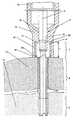
도 1은 본 발명의 뼈 스크류의 실시예의 단면도이다.1 is a cross-sectional view of an embodiment of a bone screw of the present invention.
도 2는 도 1에 도시된 실시예의 단면도, 이식 기구, 및 스크류 드라이버를 도시한다.FIG. 2 illustrates a cross-sectional view, implant mechanism, and screw driver of the embodiment shown in FIG. 1.
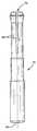
도 3A는 압축 슬리브의 실시예의 측면도이다.3A is a side view of an embodiment of a compression sleeve.
도 3B는 도 3A의 압축 슬리브의 단면도이다.3B is a cross-sectional view of the compression sleeve of FIG. 3A.
도 3C는 도 3A 및 도 3B의 압축 슬리브의 부분 확대 단면도이다.3C is a partially enlarged cross-sectional view of the compression sleeve of FIGS. 3A and 3B.
도 4A는 도관 스크류드라이버의 실시예의 측면도이다.4A is a side view of an embodiment of a conduit screwdriver.
도 4B는 도 4A의 스크류드라이버의 단면도이다.4B is a cross-sectional view of the screwdriver of FIG. 4A.
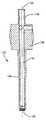
도 5A는 보호 핸들의 실시예의 측면도이다.5A is a side view of an embodiment of a protective handle.
도 5B는 도 5A의 보호 해들의 단면도이다.5B is a cross-sectional view of the protective solutions of FIG. 5A.
도 6A는 도 5A 및 도 5B의 보호 핸들과 함께 사용하기 위한 연결 부재의 측면도이다.6A is a side view of the connecting member for use with the protective handle of FIGS. 5A and 5B.
도 6B는 도 6A의 연결 부재의 단면도이다.6B is a cross-sectional view of the connecting member of FIG. 6A.
도 7A는 복합-도구의 실시예의 측면도이다.7A is a side view of an embodiment of a multi-tool.
도 7B 및 도 7C는 도 7A의 복합-도구의 단면도들이다.7B and 7C are cross-sectional views of the multi-tool of FIG. 7A.
도 8A는 도 7A의 복합-도구와 함께 사용하기 위한 압축 슬리브의 단면도이다.8A is a cross-sectional view of the compression sleeve for use with the compound tool of FIG. 7A.
도 8B는 도 8A의 압축 슬리브의 확대 단면도이다.8B is an enlarged cross-sectional view of the compression sleeve of FIG. 8A.
도 9A는 도 7A의 복합-도구와 함께 사용하기 위한 핸들의 측면도이다.9A is a side view of the handle for use with the multi-tool of FIG. 7A.
도 9B는 도 9A의 핸들의 단면도이다.9B is a cross-sectional view of the handle of FIG. 9A.
도 10A는 도 7A의 복합-도구와 함께 사용하기 위한 도관 스크류드라이버와 잠금 칼라(collar)의 측면도이다.FIG. 10A is a side view of a conduit screwdriver and locking collar for use with the multi-tool of FIG. 7A.
도 10B는 도 10A의 도관 스크류드라이버와 잠금 칼라의 단면도이다.10B is a cross sectional view of the conduit screwdriver and locking collar of FIG. 10A.
도 10C는 도 10A 및 도 10B의 도관 스크류드라이버의 결합부의 확대 측면도이다.10C is an enlarged side view of the coupling of the conduit screwdriver of FIGS. 10A and 10B.
도 10D는 도 10C의 확대부의 단면도이다.10D is a cross-sectional view of the enlarged portion of FIG. 10C.
도 11A는 도 7A의 복합-도구와 함께 사용하기 위한 잠금 링의 측면도이다.FIG. 11A is a side view of the locking ring for use with the multi-tool of FIG. 7A.
도 11B는 도 11A의 잠금 링의 단면도이다.FIG. 11B is a cross-sectional view of the locking ring of FIG. 11A.
도 12A는 도 7A의 복합-도구와 함께 사용하기 위한 잠금 칼라의 측면도이다.12A is a side view of the locking collar for use with the compound tool of FIG. 7A.
도 12B는 도 12A의 잠금 칼라의 끝단을 도시한다.Figure 12B shows the end of the locking collar of Figure 12A.
도 12C는 도 12A의 잠금 칼라의 단면도이다.12C is a cross-sectional view of the locking collar of FIG. 12A.
도 13A는 플라스틱-밀봉 스크류와 함께 사용하기 위한 6각-모양 입구를 가진 압축 슬리브의 실시예의 측면도이다.13A is a side view of an embodiment of a compression sleeve with a hexagonal-shaped inlet for use with a plastic-sealing screw.
도 13B는 도 13A의 압축 슬리브의 확대 측면도이다.FIG. 13B is an enlarged side view of the compression sleeve of FIG. 13A.
도 13C는 도 13A의 압축 슬리브의 부분 확대 단면도이다.FIG. 13C is a partially enlarged cross-sectional view of the compression sleeve of FIG. 13A.
도 14A는 스크류와 함께 사용하기 위한 플라스틱 시일의 측면도이다.14A is a side view of a plastic seal for use with a screw.
도 14B는 도 14A의 플라스틱 시일의 단면도이다.14B is a cross-sectional view of the plastic seal of FIG. 14A.
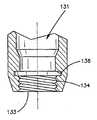
도 1에는 본 발명에 따른 뼈 스크류(1)의 바람직한 실시예가 도시되어 있다. 상기 뼈 스크류(1)는 중심 직경(DKH), 외경(DHS) 및 피치(SH)를 가진 외부 나사산(9)이 마련된 후방 나사 부분(7)과, 세로축(2)과 동축이고 후방 나사 부분(7)과 인접하며 외경(DMS)을 가진 중간의 나사가 없는 부분(6), 및 중심 직경(DKV), 외경(DVS) 및 피치(SV)를 가진 외부 나사산(8)이 마련된 전방 나사 부분(5)을 포함한다. 두 개의 나사 부분들(5)(7)은 다른 직경들을 가지며, 즉 후방 나사 부분(7)의 중심 직경(DKH)은 전방 나사 부분(5)의 외경(DVS)보다 크거나 같다. 두 개의 외부 나사산들(8)(9)의 피치들은 동일할 수도 있고, 서로 다를 수도 있다. 또한, 전방 나사 부분(5)의 리드(lead)는 후방 나사 부분(7)의 리드와 같거나 다를 수 있다. 중간 부 분(6)의 외경(DMS)은 후방 나사 부분(5)의 중심 직경(DKV)보다 작거나 동일하다. 또한, 뼈 스크류(1)의 전단(3)과, 후방 나사 부분(7)과 중간 부분(6) 사이의 전이부에는, 두 개의 나사 부분들(5)(7)의 테두리 위에 분포되고 축방향으로 정렬될 수 있는 몇 개의 깔쭈기들(23)이 세로축(2)에 실질적으로 평행한 절단 가장자리(12)에 배치되어, 이러한 두 개의 외부 나사산들(8)(9)은 자체적으로 깍인 나사산으로서 구성된다. 예를 들어, 6각형 리세스, Torx® 또는 Phllips와 같은 스크류드라이버를 수용하기 위한 수단(11)이 뼈 스크류(1)의 후단(4)에는 동축적으로 배치된다. 또한, 뼈 스크류(1)는 전단(3)으로부터 후단(4)까지 확장하고, 예를 들어 가이드 와이어(미도시)를 수용하는 작용을 하는 중앙 구멍(10)을 가지고 있다.1 shows a preferred embodiment of a
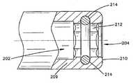
도 2에는 본 발명에 따른 장치가 뼈 스크류(1)와 함께 도시되어 있고, 후방 나사 부분(7)의 일부는 이식 기구(15)와 나사 결합되고, 그 전방 나사 부분(5)은 원위의 뼈 조각(14)에 완전히 나사 결합되어 있다. 이식 기구(15)는 전단(18)으로부터 깊이(T)까지 확장된 연속적인 중앙 구멍(17)과, 외부 나사산(9)과 상보하는 내부 나사산(20)을 가진 확장 부분(24)을 포함한다. 깊이(T)에서, 중앙 구멍(17)의 확장 부분(24)과 중앙 구멍(17)의 좁은 부분(25) 사이에는, 후방 나사 부분(7)이 이식 기구(15)에 완전히 나사 결합될 때 거기에 기대어 뼈 스크류(1)의 후단(4)이 안착되는 숄더(22)가 존재한다. 스크류드라이버(16)는 이식 기구(15)의 후단(19)으로부터 중앙 구멍(17)의 좁은 부분(25)을 관통할 수 있으므로, 스크류드라이버(16)는 스크류드라이버를 수용하기 위해 뼈 스크류(1)의 후단(4)에 배치된 수단(11) 속 으로 삽입될 수 있고, 뼈 스크류(1)는 스크류드라이버(16)에 의해 이식 기구(15)에 대해 회전될 수 있다.2 shows a device according to the invention with a
두 개의 뼈 조각들(13)(14)을 셋팅, 압축 및 고정하기 위해, 근위의 뼈 조각(13)을 통해 원위의 뼈 조각(14) 속으로 관통하는 구멍(21)이 생성될 수 있다. 구멍(21)의 직경은 뼈 스크류(1)의 전방 나사 부분(5)의 외부 나사산(8)의 중심 직경(DKV)(도 1)과 상응한다. 구멍(21)은 선택적일 수 있지만, 뼈 스크류(1)가 자체-천공(self-drilling)일 때 특히 그러하다.In order to set, compress and secure the two
이식 과정의 초기에, 뼈 스크류(1)의 후방 나사 부분(7)은 이식 기구(15)의 중앙 구멍 속으로 완전히 그리고 내부 나사산(20)의 깊이(T)까지 나사 결합된다. 이식 기구(15)를 세로축(2)에 대해 회전시키게 되면, 뼈 스크류는 두 개의 뼈 조각들(13)(14)에 미리-천공된 구멍들(21) 속으로 나사 결합될 수 있다. 뼈 스크류(1)의 후방 나사 부분(7)은 이식 기구(15)에 완전하게 자리잡고 있기 때문에, 후방 나사 부분(7)의 외부 나사산(9)은 근위의 뼈 조각(13)에 결합되지 않게 되므로, 이식 기구(15)가 회전될 때, 뼈 스크류(1)의 전방 나사 부분(5)만 원위의 뼈 조각(14)에 나사 결합될 수 있다. 이 단계에서, 이식 기구(15)의 전단(18)은 스크류 헤드의 임무를 띠게 되어, 이식 기구(15)의 전단(18)이 근위의 뼈 조각(14)에 마주하여 놓여질 만큼 뼈 스크류(1)가 두 개의 뼈 조각들(13)(14)에 도달한 후에, 이식 기구(15)의 추가적인 회전에 의해 두 개의 뼈 조각들(13)(14)은 서로를 향해 이동하게 된다. 두 개의 뼈 조각들(13)(14)이 서로 접촉하게 되면, 두 개의 뼈 조각들(13)(14) 의 압축은 시작된다. 이식 기구(15)의 추가적 회전에 의해 두 개의 뼈 조각들(13)(14)의 바람직한 압축이 이루어지게 되면, 스크류드라이버(16)는 이식 기구(15)에 있는 중앙 구멍(17)을 통해 스크류드라이버를 수용하기 위한 수단(11) 속으로 삽입되고 뼈 스크류(1)는 스크류드라이버(16)와 함께 더 회전되므로, 이식 기구(15)는 그 자리에 유지되고, 뼈 스크류(1)는 이식 기구(15)의 전단(18)에 있는 내부 나사산(20)으로부터 나사가 풀리고, 후방 나사 부분(17)이 근위의 뼈 조각(13)의 표면 아래에 완전히 도달할 때까지 후방 나사 부분(7)은 근위의 뼈 조각(13)에 나사 결합된다. 두 개의 뼈 조각들(13)(14)은 이러한 최종 단계 동안 서로에 대해 움직이지 않고, 후방 나사 부분(7)이 근위의 뼈 조각(13)에 박힌 후에 압축은 변화되지 않을 수 있다.At the beginning of the implantation process, the
바람직하게, 뼈 스크류(1)는 스크류 헤드가 예를 들어, 관절 부근의 골절, 주상골(scaphoid) 골절과 같은 관절내(intraarticular) 고정, 작은 조각 그리고 근육, 신경 및 혈관 근처의 고정을 방해할 수 있는 곳에 사용된다. 뼈 스크류(1)는 뼈 플레이트(미도시)와 협력하여 또는 그 근처에 역시 사용될 수 있다.Preferably, the
도 3A 내지 도 3C는 뼈 스크류와 함께 사용하기 위한 압축 슬리브(compression sleeve)(30)의 실시예를 도시한다. 도 3A에 도시된 바와 같이, 압축 슬리브(30)는 선단(32), 후단(34) 및 후단(34) 근처에 배치된 파지부(36)를 구비할 수 있다. 도 3B에 도시된 바와 같이, 압축 슬리브(30)는 슬리브(30)를 관통하여 뻗어 있으며, 선단 구멍(40)과 후단 구멍(42) 사이에 걸쳐 있는 구멍(38)을 가질 수 있다. 도 3C에는 압축 슬리브(30)의 선단(32)의 확대도가 도시되어 있다. 내 부 나사산(44)은 슬리브(30)의 선단(32)과 선단 구멍(40) 및/또는 근처에 배치될 수 있다. 슬리브(30)는 내부 나사산(40)과 인접하여 배치된 숄더(46)를 또한 가질 수 있다. 숄더(46)는 뼈 스크류(1)가 슬리브(30)의 구멍(38) 속으로 너무 멀리 돌출되는 것을 방지하도록 크기를 가질 수 있다. 뼈 스크류(1)의 후방 나사 부분(7)이 내부 나사산(40)에 충분히 결합할 수 있도록 숄더(46)는 구멍(38) 내부에 위치될 수 있다. 압축 슬리브(30)는 상술된 바와 같은 이식 기구(15)로서 실질적으로 유사한 방식으로 사용될 수도 있다.3A-3C show an embodiment of a
도 4A 및 도 4B는 뼈 스크류(1)와 함께 사용하기 위한 스크류드라이버(50)의 실시예를 도시한다. 도 4A에 도시된 바와 같이, 스크류드라이버(50)는 결합단(52), 후단(54), 및 표시부(56a)(56b)(56c)를 가질 수 있다. 스크류드라이버(50)는 핸들과 결합하는 것을 도울 수 있는, 후단(54) 또는 그 근처에 있는 함몰부(58)를 역시 가질 수 있다. 도 4B의 단면도에 도시된 바와 같이, 스크류드라이버(50)는 선단 구멍(62)과 후단 구멍(64) 사이로 뻗어 있는 구멍(60)을 가질 수 있다. 스크류드라이버는 스크류드라이버(16)와 관련하여 상술한 것과 유사한 방식으로 뼈 스크류와 결합하기 위한 결합부(66)를 역시 가질 수 있다. 결합부(66)는 뼈 스크류(1)와 효과적으로 결합하기 위해 그 어떤 선택된 모양을 가질 수 있다.4A and 4B show an embodiment of a
표시부(56a)(56b)(56c)는 뼈 또는 조직에서 뼈 스크류(1)의 삽입의 깊이를 결정하는 것을 도울 수 있다. 압축 슬리브 또는 다른 이식 기구 속으로 삽입되었을 때, 표시부(56a)(56b)(56c)는 사용시 완전히 또는 부분적으로 보여질 수 있다. 스크류드라이버(50)의 결합부(66)가 뼈 스크류(1)의 수납부(상술한 수단(11)으로서 도시된 실시예)와 결합할 때, 뼈 스크류(1)는 뼈 또는 조식에 더 삽입되어, 압축 슬리브(30)의 내부 나사산(40)으로부터 풀리게 될 수 있다. 스크류드라이버(50)가 슬리브(30)의 구멍(38) 속으로 더 삽입되면, 표시부(56c)가 슬리브(30)에 의해 덮히는 것과 같이, 표시부(56a)(56b)(56c)는 점진적으로 덮히게 되고, 뼈 스크류(1)는 뼈 또는 조직 속으로 완전히 삽입될 수 있다.The
도 5A 및 도 5B는 본 명세서에서 설명된 도구와 함께 사용하기 위한 핸들(70)의 실시예를 도시한다. 도 5A의 측면도에 도시된 바와 같이, 핸들(70)은 파지부(72), 및 선단 구멍(76)과 확장 가능한 핑거들(82)을 가진 연결 부재(74)를 가질 수 있다. 연결 부재(74)는 별도의 분리된 부품(도 6A 및 도 6B에 도시)일 수 있으며, 구멍(42)을 통해 압축 슬리브(30) 속으로 적어도 부분적으로 삽입될 수 있다. 확장 가능한 핑거들(82)은 보다 안전한 접합을 생성하기 위해 압축 슬리브(30)의 구멍(38) 내부에 탄력 있게 수축되는 것이 유익할 수 있다. 도 5B의 단면도에 도시된 바와 같이, 핸들(70)은 연결 부재(74)를 수납하기 위한 구멍(78)을 역시 가질 수 있다. 수납부(74)는 그곳을 통해 가이드 와이어(미도시)의 일 부분을 수납하기 위한 구멍(80)을 역시 가질 수 있다.5A and 5B show an embodiment of a
도 6A 및 도 6B는 연결 부재(74)의 실시예를 더 상세히 도시한다. 도 6A의 측면도 및 도 6B의 단면도에 도시된 바와 같이, 연결 부재(74)는 선단 구멍(76), 후단 구멍(86)과 그들 사이에 뻗어 있는 구멍(80)을 가질 수 있다. 연결 부재(74)는 선단(85)과 후단(86)을 또한 가진다. 구멍(80)은 가이드 와이어(미도시)를 고정하는 크기 및 치수를 가질 수 있다.6A and 6B show an embodiment of the connecting
사용시, 핸들(70)은 사용자가 뼈 스크류(1)를 뼈 분절 속으로 삽입하기 위한 안전하고 인간공학적 방식을 제공하는 것이 유용하다. 우선, 가이드 와이어는 요구되는 위치에서 뼈 분절 속으로 삽입될 수 있다. 뼈 스크류(1)가 내부 나사산들(40)과 이미 결합된 상태에서 압축 슬리브(30)는 핸들(70)과 결합될 수 있고, 그 후 뼈 스크류(1)의 전단(3)이 뼈 표면에 인접하도록 가이드 와이어 위로 삽입된다. 이러한 배치에 있어서, 연결부(74)는 그 후단 구멍(42)을 통해 압축 슬리브(30)와 결합하고, 가이드 와이어의 자유단은 핸들(70)의 구멍(78)에 수용된다. 그 후, 뼈 스크류(1)는 뼈 표면 속으로 삽입되어 가이드 와이어의 노출된 자유단이 핸들에 안전하게 수납되도록 한다. 뼈 스크류(1)가 뼈 표면 속으로 요구되는 깊이까지 삽입된 후, 핸들(70)과 연결부(74)는 압축 슬리브(30)로부터 풀려질 수 있고, 뼈 스크류(1)를 뼈 표면 속으로 더 삽입하고/또는 뼈 스크류(1)를 압축 슬리브(30)로부터 풀도록 스크류드라이버(50)는 결합될 수 있다. 따라서, 핸들(70)과 압축 슬리브(30)의 구성과 이동 가능한 결합은 가이드 와이어의 자유단으로부터 사용자에 대한 보호를 제공하고, 또한 뼈 스크류(1)를 뼈 표면 속으로 적어도 부분적으로 삽입하는 인간공학적 방법이 제공된다.In use, the
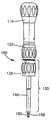
도 7A 내지 도 7C는 뼈 스크류(1)와 함께 사용될 수 있는 다른 형태의 도구, 복합-도구(100)의 실시예를 도시한다. 도 7A의 측면도 및 도 7B와 도 7C의 단면도들에 도시된 바와 같이, 복합-도구(100)는 핸들(110), 잠금 칼라(locking collar)(115), 잠금 링(120), 파지부(135)와 샤프트부(140)를 가진 압축 슬리브(130), 선단부(158)를 가진 스크류드라이버(150), 그곳을 관통하는 구멍(160)을 가질 수 있다.7A-7C show an embodiment of another type of tool, the compound-
사용시, 복합-도구(100)는 본 명세서에서 설명된 다른 장치들의 그것과 실질적으로 유사한 방식으로 기능할 수 있다. 복합-도구(100)와 본 명세서에서 설명된 다른 장치들 사이의 하나의 차이점은 뼈 스크류(1)가 스크류드라이버(150)의 도움으로 그리고 그것의 도움없이 적어도 부분적으로 삽입되는 것을 허용하는 선택적인 결합 특징을 복합-도구(100)가 가질 수 있다는 것이다. 아래에서 보다 상세히 설명된 바와 같이, 잠금 칼라(115)와 잠금 링(120) 사이의 선택적인 잠금 배치는 압축 슬리브(130)가 핸들(110)과 스크류드라이브(150)와의 관계에서 고정되었는지 여부를 선택적으로 결정할 수 있다. 구멍(160)은 복합-도구(100)의 전체를 통틀어 관통할 수 있는 것과 같이, 가이드와이어(미도시)는 보다 정밀하고 정확한 배치와 도구(100)의 사용을 위해 이용될 수 있다.In use, the
도 8A 및 도 8B는 복합-도구(100)와 함께 사용하기 위한 압축 슬리브(130)의 실시예를 도시한다. 압축 슬리브(130)는 상술한 압축 슬리브(30)와 이식 기구(15)에 대한 디자인 및 기능과 실질적으로 유사할 수 있다. 압축 슬리브(130)는 선단 구멍(133)과 후단 구멍(132) 사이로 뻗어 있는 구멍(131)을 가질 수 있다. 슬리브(130)는 파지부(135)와 샤프트(140)를 역시 가질 수 있다. 위에서 논의된 압축 슬리브(30)와 유사하게, 슬리브(130)는 뼈 스크류(1)와 결합하기 위한 내부 나사산(134), 및 구멍(131) 내부에서 뼈 스크류(1)의 이동을 제한하기 위한 숄더(136)를 또한 구비할 수 있다. 압축 슬리브(130)는 잠금 링(120)이 보조 샤프트 위에 수용될 때, 잠금 링(120)이 압축 슬리브(130)에 대해 회전할 수 없도록 잠금 링(120) 을 수납하기 위해, 다각형 또는 비-원형(non-circular) 모양 중 어느 하나인, 보조 샤프트부(139)를 또한 가질 수 있다. 그러한 바와 같이, 비록 잠금 링(120)이 보조 샤프트부(139)에 미끄러지게 결합되더라도, 압축 슬리브(130)와 잠금 링(120)은 사용시 회전되게 고정된다.8A and 8B show an embodiment of a
도 9A 및 도 9B는 복합-도구(100)와 함께 사용하기 위한 핸들(110)의 실시예를 도시한다. 핸들(110)은 선단 구멍(113)과 후단 구멍(114) 사이로 뻗어 있는 구멍(111)을 가질 수 있다. 핸들(110)은 사용자의 파지력을 개선하기 위한 홈들(192)을 가진 파지부(190)를 또한 가질 수 있다. 핸들(110)은 또한 잠금 칼라(115)의 적어도 일 부분을 수용할 수 있으며, 적어도 부분적으로 구멍(114)과 협력하는, 확대된 챔버(112)를 가질 수 있다. 바람직하게, 핸들(110)은 고정 구멍들(194) 속으로 삽입된 파스너(fastener)(미도시)에 의해 잠금 칼라(115)에 고정적으로 부착된다.9A and 9B show an embodiment of a
도 10A 내지 도 10D는 복합-도구(100)와 함께 사용하기 위한 도관(cannulated) 스크류드라이버(150)의 실시예를 도시한다. 스크류드라이버(150)는 전술한 스크류드라이버들(16)(50)과 실질적으로 유사할 수 있다. 스크류드라이버(150)는 선단(152), 후단(154), 구멍(156), 및 선단(152) 및/또는 그 부근에 있는 선단부(158)를 구비할 수 있다. 도 10A 및 도 10B에 도시된 바와 같이, 스크류드라이버(150)는 잠금 칼라(115)와 상호 작용하는 크기일 수 있다. 선단부(158)는 도 10C 및 도 10D에 더 자세히 도시된다. 선단부(158)는 뼈 스크류(1)와 결합하기 위한 결합부(157)를 가질 수 있다. 선단부(158)는 스크류드라이버(150)와 동축적이지만 그것보다 감소된 지름을 가진 구멍(159)을 가질 수 있다. 선단부(158)는 스크 류드라이버(150)의 분리되고 구별되는 부품일 수 있으며, 따라서, 스크류드라이버(150)의 구멍(156) 속으로 적어도 부분적으로 삽입될 수 있다. 선단부(158)의 그 어떤 그리고 모든 특징들은 스크류드라이버(16)(50)와 함께 사용될 수 있다. 스크류드라이버(150)는 사용시 핸들(110)에 고정적으로 부착될 수 있다.10A-10D show an embodiment of a cannulated
도 11A 및 도 11B는 복합-도구(100)와 함께 사용하기 위한 잠금 링(120)의 실시예를 도시한다. 도 11A의 측면도 및 도 11B의 단면도에 도시된 바와 같이, 잠금 링(120)은 파지를 돕기 위한 홈들(122), 제1 단(124), 제2 단(126), 제1 구멍(125), 및 제2 구멍(123)을 가질 수 있다. 잠금 링(120)은 잠금 링(120)의 구멍(cavity)(129) 내부에 돌출하는 잠금 부재들(127a)(127b)을 또한 가질 수 있다. 잠금 부재들(127a)(127b)은 위에서 설명된 바와 같이, 잠금 칼라(115)의 홈들(118)과 결합할 수 있다. 잠금 링(120)은 하나, 두 개, 세 개, 또는 그 이상의 잠금 부재들을 가질 수 있다. 잠금 링(120)의 내면(121)은 바람직하게 압축 슬리브(130)의 보조 샤프트부(139)의 모양과 치수들에 상응한다.11A and 11B show an embodiment of a
도 12A 내지 도 12C는 복합-도구(100)와 함께 사용하기 위한 잠금 칼라(115)의 실시예를 도시한다. 도 12A의 측면도, 도 12B의 정면도, 및 도 12C의 단면도에 도시된 바와 같이, 잠금 칼라(115)는 핸들(110) 속으로의 삽입을 위한 삽입단(117)과, 잠금 링(120)과의 결합을 위한 결합단(119)을 가질 수 있다. 잠금 칼라(115)는 끝단들(117)(119) 사이로 뻗어 있는 구멍(116)을 또한 가질 수 있다. 도 12B에 더 상세히 도시된 바와 같이, 잠금 칼라(115)의 결합단(119)은 구멍(116) 주위에 배치된 복수의 홈들(118)을 가질 수 있다. 몇몇 홈들(118)은 잠금 링(120)의 잠금 부재 들(127a)(127b)과 결합할 수 있다. 잠금 칼라(115)는 핸들(100)의 고정 구멍들(194)과 정렬될 수 있는, 고정 구멍들(196) 속으로 삽입되어 있는 파스너들에 의해 핸들(110)에 고정적으로 부착된다. 고정 구멍들(194)(196)은 나사산이 형성될 수 있다.12A-12C show an embodiment of a
잠금 칼라(115)는 스크류드라이버(50)의 표시부(56a)(56b)(56c)(상술 됨)와 같이 실질적으로 유사한 방식으로 이용될 수 있는 표시부(191a)(191b)(191c)를 또한 가질 수 있으므로, 뼈 스크류(1)가 뼈 또는 조직 안으로 삽입이 진행될 때, 표시부(191a)(191b)(191c)는 점진적으로 덮히게 된다. 표시부(56)(191)는 다양한 간격들로서 이격될 수 있다. 표시부(56)(191)는 대략 2mm로 이격되는 것이 바람직하다.The
잠금 칼라(115)와 잠금 링(120)의 결합과 분리가 설명될 것이다. 내부 나사산(134)이 뼈 스크류(10)의 후방 나사 부분(7)에 결합됨에 의해 뼈 스크류(1)가 압축 슬리브(130)에 나사 결합된 후, 잠금 링(120)의 잠금 부재들(127)이 잠금 칼라(115)의 홈들(118)에 결합되도록 복합-도구(100)는 정렬된다. 이러한 구성에 있어서, 전체 복합-도구(100)는 실질적으로 통합 도구이다. 그 후, 뼈 스크류(1)를 뼈 또는 조직 속으로 요구되는 깊이만큼 삽입하기 위해 복합-도구(100)는 회전 및/또는 조작되지만, 바람직하게 압축 슬리브(130)의 선단(133)은 뼈 또는 조직 표면 근처가 되도록 한다. 이 점에서, 잠금 부재들(127)이 잠금 칼라(115)의 홈들(118)과 분리되도록 잠금 링(120)은 장치의 원위단 쪽으로 미끄러질 수 있다. 잠금 링(120)은 그것이 압축 슬리브(130)에 접촉하는 지점까지 이 방향으로 미끄러지는 것이 바람직하다. 잠금 링(120)이 분리된 후, (스크류드라이버(150)와 잠금 칼라(115)가 고정적으로 부착된 상태에서) 핸들(110)은 뼈 스크류(1)를 뼈 또는 조직 속으로 더 삽입하기 위해 회전될 수 있는 반면, 동시에 후방 나사 부분(7)을 압축 슬리브(130)의 내부 나사산(134)으로부터 분리시킨다. 스크류드라이버(150)의 결합부(157)가 이제는 뼈 스크류(1)와 결합하는 것과 그 구멍(131) 내부에서 압축 슬리브(130)의 자유로운 회전이 허용되기 때문에 이것이 달성된다.Coupling and detachment of the
도 13A 내지 도 14B는 압축 슬리브(200)의 다른 실시예와 뼈 스크류(1)와 함께 사용하기 위한 플라스틱 시일(seal)(220)의 다른 실시예를 도시하며, 따라서, 본 발명의 모든 목적들은 여기서 설명된다. 도 13A의 측면도, 도 13B의 확대 측면도, 및 도 13C의 부분 단면도에 도시된 바와 같이, 압축 슬리브(200)는 선단(204)과 후단(206) 사이에 걸쳐 있는 구멍(202)을 가질 수 있다. 구멍(202)은 하나의 직경 이상을 가질 수 있다. 압축 슬리브(200)는 샤프트부(208), 및 선단(210)을 가진 팁부(209)를 또한 가질 수 있다. 도 13B 및 도 13C에서 더 상세히 도시된 바와 같이, 팁부(209)는 플라스틱 시일(220)(도 14A 및 도 14B 참조)의 일 부분을 수용하기 위한 육각-모양의 내면(212)을 가질 수 있다. 내면(212)은 팁부(209) 안에서의 플라스틱 시일(220)의 회전 운동을 제한하기 적당한 다른 모양들을 또한 가질 수 있다. 팁부(209)는 플라스틱 시일(220)의 일 부분을 탄성적으로 확보하기 위해 선단(210) 근처에 배치된 링(214)을 또한 가질 수 있다. 링(214)은 플라스틱 시일(220)의 일 부분이 링(214)에 결합하는 것을 허용하는 한편 플라스틱 시일(220)이 링을 지나 구멍(202) 속으로 미끄러지는 것도 허용하기 위해 탄성적으로 변형될 수 있다.13A-14B show another embodiment of a
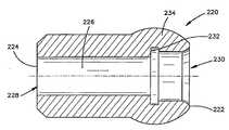
도 14A 및 도 14B는 압축 슬리브(200) 및 뼈 스크류(1)와 함께 사용하기 위한 플라스틱 시일(220)의 실시예를 도시한다. 도 14A의 측면도 및 도 14B의 단면도에 도시된 바와 같이, 시일(220)은 선단(222)과, 삽입단(224), 및 선단 구멍(230)과 후단 구멍(228) 사이로 뻗어 있는 구멍(226)을 가질 수 있다. 시일(220)은 뼈 스크류(1)의 일 부분을 수용하기 위한 구형(bulbous) 선단부(234)를 또한 가질 수 있다. 선단부(234)의 내면은 디자인 및 기능에서 전술한 숄더(22)(46)(136)와 유사한 숄더(232)를 가질 수 있다. 선단부(234)의 내면은 나사산일 수도 그렇지 않을 수도 있다. 일 실시예에 있어서, 상기 내면은 나사산이 아닐 수 있으며, 뼈 스크류(1)는 축력(axial force)에 의해 선단부(234)에 삽입된다. 다른 실시예에 있어서, 상기 내면은 나사산이며, 뼈 스크류(1)는 선단부(234) 내부에 나사결합되어 수납된다. 시일(220)은 또한 뼈 스크류(10)의 적어도 일 부분 위에 성형될 수 있다. 시일(220)은, 압축 슬리브(200)의 육각-모양의 내면(212) 속으로 삽입될 수 있는 육각-모양의 외면(236)을 삽입단(224) 또는 그 근처에서 또한 가질 수 있다. 육각-모양의 표면들 이외의 다른 모양들도 사용될 수 있다. 시일(220)은 바람직하게 플라스틱으로 제조되고 바람직하게 단일-용도의, 일회용 물품이다.14A and 14B show an embodiment of a
사용 시, 뼈 스크류(1)는 시일(220)의 선단 구멍(230) 속으로 삽입되고, 시일(220)의 육각-모양의 외면(236)이 압축 슬리브(200)의 육각-모양의 내면(212)과 결합하도록 삽입단(224)은 압축 슬리브(200)의 선단 구멍(204) 내부에 삽입된다. 뼈 스크류(1)는 그 후 뼈 또는 조직 속으로 요구되는 깊이까지 부분적으로 삽입된 다. 그 후, 압축 슬리브(200)의 구멍(206)을 통해 스크류(1)를 뼈 또는 조직 속으로 더 삽입하기 위해, 뼈 스크류(1)는 스크류드라이버에 의해 결합될 수 있고, 동시에 뼈 스크류(1)는 시일(220)로부터 분리시킨다. 뼈 스크류(1)가 시일(22)과 완전히 분리될 때까지 뼈 스크류(1)는 그렇게 결합된다. 플라스틱 시일(220)은 그 후 압축 슬리브(200)로부터 제거되어 폐기될 수 있다.In use, the
뼈 스크류(1)는 뼈 표면과 결합되기 전에 도구(15) 또는 압축 슬리브(30)(130)(200) 속으로 완전히 또는 부분적으로 삽입될 수 있다. 뼈 스크류(1)의 나사부들은 다양한 피치, 길이, 직경을 가질 수 있고, 뼈 스크류(1)에 있는 다른 나사 부분들은 동일하거나 다른 피치, 길이, 및 직경을 가질 수 있다. 특징들의 다양한 결합들은 당업자에 의해 알 수 있을 것이다.The
몇몇 실시예들로부터 도출되는 특징들은 다른 실시예들로부터 도출되는 특징들과 결합, 통합 또는 상호 교환될 수 있음을 명백히 하고자 한다. 이러한 의미에서, 본 명세서에서 설명된 도구들의 설명된 구성요소들은 사실상 "기준(modular)"이다. 그러한 결합들은 그 변형들에 부가하여 당업자에 의해 평가될 것이다.It is intended to be clear that features derived from some embodiments may be combined, integrated or interchanged with features derived from other embodiments. In this sense, the described components of the tools described herein are in fact "modular". Such combinations will be assessed by those skilled in the art in addition to the variations.
본 발명은 본 명세서에서 특정의 실시예들을 참조하여 도시되고 설명되었지만, 본 발명의 정신과 범위를 벗어나지 않는 범위 설명된 실시예들에 대한 형태, 구조, 정렬, 성분, 물질 및 속성에 대한 부가, 대체 또는 변형들이 가능하다는 것을 이해할 것이다. 따라서, 본 명세서에서 설명된 실시예들은 본 발명의 원칙들을 단지 설명할 뿐이고, 본 발명의 원칙을 구현하고 본 발명의 정신과 범위에 속하게 될 당업자에 의한 다양한 변형들이 가능하다는 것을 이해해야 한다.While the invention has been shown and described with reference to specific embodiments herein, additions, substitutions to forms, structures, arrangements, components, materials and attributes of the described embodiments without departing from the spirit and scope of the invention. Or it will be understood that variations are possible. Accordingly, it is to be understood that the embodiments described herein merely illustrate the principles of the invention, and that various modifications are possible by those skilled in the art that implement the principles of the invention and will fall within the spirit and scope of the invention.
Claims (30)
Translated fromKoreanApplications Claiming Priority (3)
| Application Number | Priority Date | Filing Date | Title |
|---|---|---|---|
| US11/205,829US8216243B2 (en) | 2001-12-04 | 2005-08-16 | Headless compression screw with integrated reduction-compression instrument |
| US11/205,829 | 2005-08-16 | ||
| PCT/US2006/031977WO2007022261A2 (en) | 2005-08-16 | 2006-08-15 | Headless compression screw with integrated reduction-compression instrument |
Publications (2)
| Publication Number | Publication Date |
|---|---|
| KR20080042825Atrue KR20080042825A (en) | 2008-05-15 |
| KR101277775B1 KR101277775B1 (en) | 2013-06-27 |
Family
ID=37561112
Family Applications (1)
| Application Number | Title | Priority Date | Filing Date |
|---|---|---|---|
| KR1020087003694AActiveKR101277775B1 (en) | 2005-08-16 | 2006-08-15 | Headless compression screw with integrated reduction-compression instrument |
Country Status (11)
| Country | Link |
|---|---|
| US (3) | US8216243B2 (en) |
| EP (2) | EP1916955B1 (en) |
| JP (1) | JP5153633B2 (en) |
| KR (1) | KR101277775B1 (en) |
| CN (1) | CN101304699B (en) |
| AU (1) | AU2006279529A1 (en) |
| BR (1) | BRPI0615212B8 (en) |
| CA (2) | CA2619047C (en) |
| TW (1) | TWI468145B (en) |
| WO (1) | WO2007022261A2 (en) |
| ZA (1) | ZA200801473B (en) |
Families Citing this family (56)
| Publication number | Priority date | Publication date | Assignee | Title |
|---|---|---|---|---|
| WO2003047444A1 (en)* | 2001-12-04 | 2003-06-12 | Synthes Ag Chur | Bone screw |
| US8216243B2 (en) | 2001-12-04 | 2012-07-10 | Synthes Usa, Llc | Headless compression screw with integrated reduction-compression instrument |
| JP4709892B2 (en)* | 2005-03-24 | 2011-06-29 | シンセス ゲゼルシャフト ミット ベシュレンクテル ハフツング | Bone implant adhesion enhancer |
| US20080177333A1 (en)* | 2006-10-24 | 2008-07-24 | Warsaw Orthopedic, Inc. | Adjustable jacking implant |
| US20090005787A1 (en)* | 2007-06-28 | 2009-01-01 | Angela Crall | Device and system for implanting polyaxial bone fasteners |
| EP2398413B1 (en)* | 2009-02-10 | 2014-05-21 | Synthes GmbH | Screw with variable diameter cannulation and driver |
| US8366719B2 (en) | 2009-03-18 | 2013-02-05 | Integrated Spinal Concepts, Inc. | Image-guided minimal-step placement of screw into bone |
| US20100256688A1 (en)* | 2009-04-03 | 2010-10-07 | Stryker Trauma Gmbh | Sonic screw |
| CN102497828B (en)* | 2009-05-20 | 2015-09-09 | 斯恩蒂斯有限公司 | What patient installed retracts part |
| CN102018566B (en)* | 2009-09-17 | 2012-12-19 | 北京市春立正达医疗器械股份有限公司 | Metal mortar driver |
| US8545505B2 (en)* | 2010-01-15 | 2013-10-01 | Pioneer Surgical Technology, Inc. | Low friction rod persuader |
| US9342716B2 (en)* | 2010-02-04 | 2016-05-17 | Carefusion 303, Inc. | Software-defined multi-mode RFID read devices |
| US8394108B2 (en) | 2010-06-18 | 2013-03-12 | Spine Wave, Inc. | Screw driver for a multiaxial bone screw |
| US8512383B2 (en) | 2010-06-18 | 2013-08-20 | Spine Wave, Inc. | Method of percutaneously fixing a connecting rod to a spine |
| US8641717B2 (en) | 2010-07-01 | 2014-02-04 | DePuy Synthes Products, LLC | Guidewire insertion methods and devices |
| WO2012012328A1 (en)* | 2010-07-20 | 2012-01-26 | X-Spine Systems, Inc. | Spinal facet compression screw with variable pitch thread zones and buttress head |
| US8945193B2 (en) | 2010-07-20 | 2015-02-03 | X-Spine Systems, Inc. | Minimally invasive spinal facet compression screw and system for bone joint fusion and fixation |
| JP2013534149A (en)* | 2010-07-28 | 2013-09-02 | ジンテス ゲゼルシャフト ミット ベシュレンクテル ハフツング | System or bone fixation using biodegradable screw with radial cutout |
| EP2465454B1 (en)* | 2010-12-14 | 2015-04-08 | Stryker Trauma SA | Fixation clamp with thumbwheel |
| US9662221B2 (en)* | 2011-01-26 | 2017-05-30 | Nextremity Solutions, Inc. | Upper extremity fusion devices and methods |
| USD652138S1 (en)* | 2011-02-12 | 2012-01-10 | Eca Medical Instruments | Divoted medical instrument handle |
| DE102012104973A1 (en)* | 2011-09-22 | 2013-03-28 | Zbigniew Combrowski | Surgical instrument |
| WO2013085805A1 (en) | 2011-12-06 | 2013-06-13 | Synthes Usa, Llc | Self holding feature for a screw |
| WO2013123366A1 (en) | 2012-02-16 | 2013-08-22 | Paragon 28, Inc. | Charco-resis implant, alignment instrument, system and method of use |
| US9724149B2 (en)* | 2013-03-07 | 2017-08-08 | Warsaw Orhtopedic, Inc. | Surgical implant system and method |
| US9433445B2 (en) | 2013-03-14 | 2016-09-06 | DePuy Synthes Products, Inc. | Bone anchors and surgical instruments with integrated guide tips |
| US9504489B2 (en)* | 2013-06-12 | 2016-11-29 | Bradshaw Medical, Inc. | Cannulated medical instrument handle with an airspace |
| US9295500B2 (en) | 2013-06-12 | 2016-03-29 | Spine Wave, Inc. | Screw driver with release for a multiaxial bone screw |
| US9468479B2 (en) | 2013-09-06 | 2016-10-18 | Cardinal Health 247, Inc. | Bone plate |
| US10058368B2 (en) | 2013-12-26 | 2018-08-28 | Skeletal Dynamics, Llc | Headless compression screw |
| US9526553B2 (en)* | 2014-04-04 | 2016-12-27 | K2M, Inc. | Screw insertion instrument |
| US9855087B2 (en) | 2014-08-04 | 2018-01-02 | DePuy Synthes Products, LLC | Methods and devices for spinal screw insertion |
| CN105683593A (en)* | 2014-10-06 | 2016-06-15 | 瑞特医疗技术公司 | Torque drivers for headless threaded compression fasteners |
| CN105496501A (en)* | 2015-12-21 | 2016-04-20 | 武汉康斯泰德科技有限公司 | Threading type metal bone needle |
| US10426535B2 (en) | 2017-01-05 | 2019-10-01 | Stryker European Holdings I, Llc | Self-holding screw head |
| US10702324B2 (en) | 2017-02-27 | 2020-07-07 | Osteomed Llc | Reduction tool |
| US10433883B2 (en) | 2017-06-27 | 2019-10-08 | Medos International Sarl | Spinal screw insertion devices and methods |
| US10779872B2 (en) | 2017-11-02 | 2020-09-22 | Medos International Sarl | Bone anchor insertion instruments and methods |
| US10856924B2 (en) | 2017-12-21 | 2020-12-08 | Globus Medical Inc. | Headless compression screw driver system |
| US11832860B2 (en) | 2018-06-22 | 2023-12-05 | University Of Virginia Patent Foundation | Bone fixation system for promoting the union of a bone fracture and fusion of bones across a joint space and related methods thereof |
| US11123113B2 (en) | 2019-06-13 | 2021-09-21 | Medos International Sarl | Screw inserter instruments and methods |
| US11224472B2 (en)* | 2019-06-13 | 2022-01-18 | Medos International Sarl | Screw inserter instruments and methods |
| US12004782B2 (en) | 2020-03-26 | 2024-06-11 | Warsaw Orthopedic, Inc. | Instrument for locking orthopedic screws |
| US12059189B2 (en) | 2020-06-17 | 2024-08-13 | Arthrex, Inc. | Compression/reduction drivers for performing surgical methods |
| US11627998B2 (en) | 2020-12-11 | 2023-04-18 | Warsaw Orthopedic, Inc. | Head position and driver combination instrument |
| USD1019954S1 (en) | 2021-02-24 | 2024-03-26 | Medshape, Inc. | Dynamic compression device |
| US11291488B1 (en) | 2021-02-24 | 2022-04-05 | Medshape, Inc. | Dynamic compression devices and processes for making and using same |
| US12023068B2 (en) | 2021-03-02 | 2024-07-02 | Medshape, Inc. | Resorption-controlled compression devices and processes for making and using the same |
| US11291477B1 (en) | 2021-05-04 | 2022-04-05 | Warsaw Orthopedic, Inc. | Dorsal adjusting implant and methods of use |
| US11432848B1 (en) | 2021-05-12 | 2022-09-06 | Warsaw Orthopedic, Inc. | Top loading quick lock construct |
| US11712270B2 (en) | 2021-05-17 | 2023-08-01 | Warsaw Orthopedic, Inc. | Quick lock clamp constructs and associated methods |
| EP4312838A1 (en)* | 2021-06-22 | 2024-02-07 | Smith & Nephew, Inc. | Self-countersinking bone fastener and method for countersinking a bone fastener used in connection with an orthopedic implant |
| US11957391B2 (en) | 2021-11-01 | 2024-04-16 | Warsaw Orthopedic, Inc. | Bone screw having an overmold of a shank |
| US11679005B1 (en)* | 2022-05-26 | 2023-06-20 | Spinal Simplicity, Llc | Implant removal tool |
| US11832864B1 (en) | 2023-04-12 | 2023-12-05 | OC Medical Devices, LLC | Orthopedic implants and tools |
| US11998255B1 (en) | 2023-08-26 | 2024-06-04 | University Of Utah Research Foundation | Cannulated continuous compression screw |
Family Cites Families (31)
| Publication number | Priority date | Publication date | Assignee | Title |
|---|---|---|---|---|
| US2248054A (en)* | 1939-06-07 | 1941-07-08 | Becker Joseph | Screw driver |
| US2631584A (en)* | 1948-07-22 | 1953-03-17 | Alfred T Purificato | Fracture securing instrument |
| US4140111A (en)* | 1977-09-06 | 1979-02-20 | Morrill William E | Hand tool for inserting bone fracture pins |
| CH634742A5 (en)* | 1978-12-19 | 1983-02-28 | Synthes Ag | Device for fixing bone fragments |
| SU827050A1 (en) | 1979-03-26 | 1981-05-07 | Казанский Научно-Исследовательскийинститут Травматологии И Ортопедии | Osteosynthesis device |
| US4463753A (en) | 1980-01-04 | 1984-08-07 | Gustilo Ramon B | Compression bone screw |
| US4530355A (en)* | 1982-01-18 | 1985-07-23 | Richards Manufacturing Co., Inc. | Compression screw assembly |
| EP0209685A3 (en)* | 1985-07-12 | 1988-11-09 | Fischerwerke Arthur Fischer GmbH & Co. KG | Fixation element for osteosynthesis |
| US5324297A (en)* | 1989-01-31 | 1994-06-28 | Advanced Osseous Technologies, Inc. | Ultrasonic tool connector |
| US4963144A (en)* | 1989-03-17 | 1990-10-16 | Huene Donald R | Bone screw fixation assembly, bone screw therefor and method of fixation |
| IT1237496B (en) | 1989-10-26 | 1993-06-08 | Giuseppe Vrespa | SCREW DEVICE FOR ANCHORING BONE PROSTHESES, METHOD FOR THE APPLICATION OF SUCH DEVICE AND RELATED EQUIPMENT |
| US5019079A (en) | 1989-11-20 | 1991-05-28 | Zimmer, Inc. | Bone screw |
| DE9017101U1 (en) | 1990-12-19 | 1991-04-11 | Gerhard Hug Gmbh, 7801 Umkirch | Bone screw |
| US5766221A (en)* | 1991-12-03 | 1998-06-16 | Boston Scientific Technology, Inc. | Bone anchor implantation device |
| US6030162A (en)* | 1998-12-18 | 2000-02-29 | Acumed, Inc. | Axial tension screw |
| DE4307633C1 (en) | 1993-03-11 | 1994-05-19 | Pennig Dietmar | Screw for locking marrow-cavity pin in position - has threaded section of shank near head and opposite thread on head with unthreaded section of shank between |
| FR2706811A1 (en)* | 1993-06-25 | 1994-12-30 | Michelin & Cie | |
| US5431660A (en)* | 1993-11-30 | 1995-07-11 | Burke; Dennis W. | Spring loaded screw and driver/extractor therefor |
| US5536127A (en) | 1994-10-13 | 1996-07-16 | Pennig; Dietmar | Headed screw construction for use in fixing the position of an intramedullary nail |
| US5779704A (en) | 1996-03-19 | 1998-07-14 | Kim; Andrew C. | Bi-directional universal dynamic compression device |
| FR2758972B1 (en) | 1997-02-04 | 1999-05-07 | Eos Medical | THREADED HEAD SCREW DEVICE FOR ALLOWING FIXING OF SMALL BONE FRAGMENTS |
| US5941706A (en)* | 1997-10-20 | 1999-08-24 | Ura; Robert S. | Variable depth medical drill and method of making the same |
| DE10055888C1 (en)* | 2000-11-10 | 2002-04-25 | Biedermann Motech Gmbh | Bone screw, has connector rod receiving part with unsymmetrically arranged end bores |
| DE10129490A1 (en) | 2001-06-21 | 2003-01-02 | Helmut Mueckter | Implantable screw for stabilization of joint or bone fracture, has flexible shaft which interconnects proximal head portion and distal insertion portion of elongated screw body |
| JP2003019142A (en)* | 2001-07-05 | 2003-01-21 | Robert Reed Shokai Co Ltd | Medical driver |
| EP2314233B1 (en)* | 2001-08-08 | 2013-06-12 | Stryker Corporation | A surgical tool system with an intermediate attachment located between the handpiece and an accessory or an implant, the attachment able to transmit energy from the handpiece to the accessory or the implant and the transmission of data signals from the accessory or implant to the handpiece |
| US8216243B2 (en) | 2001-12-04 | 2012-07-10 | Synthes Usa, Llc | Headless compression screw with integrated reduction-compression instrument |
| WO2003047444A1 (en) | 2001-12-04 | 2003-06-12 | Synthes Ag Chur | Bone screw |
| DE20203439U1 (en) | 2002-03-02 | 2003-07-17 | Chen, Eduard, Dr., 69118 Heidelberg | Surgical navigation screwdriver with fixing sleeve for screws with externally threaded heads has removable grip, integral tracker attachment sleeve for navigated computer-assisted applications |
| DE10224005B4 (en) | 2002-05-29 | 2015-08-13 | Stryker Leibinger Gmbh & Co. Kg | Cutting / bending system for fitting a bone plate |
| US7582107B2 (en)* | 2003-02-03 | 2009-09-01 | Integra Lifesciences Corporation | Compression screw apparatuses, systems and methods |
- 2005
- 2005-08-16USUS11/205,829patent/US8216243B2/enactiveActive
- 2006
- 2006-08-15EPEP06801622.9Apatent/EP1916955B1/enactiveActive
- 2006-08-15CACA2619047Apatent/CA2619047C/enactiveActive
- 2006-08-15KRKR1020087003694Apatent/KR101277775B1/enactiveActive
- 2006-08-15AUAU2006279529Apatent/AU2006279529A1/ennot_activeAbandoned
- 2006-08-15EPEP12000073.2Apatent/EP2460485B1/enactiveActive
- 2006-08-15JPJP2008527102Apatent/JP5153633B2/ennot_activeExpired - Fee Related
- 2006-08-15WOPCT/US2006/031977patent/WO2007022261A2/enactiveApplication Filing
- 2006-08-15CNCN200680038257XApatent/CN101304699B/enactiveActive
- 2006-08-15ZAZA200801473Apatent/ZA200801473B/enunknown
- 2006-08-15BRBRPI0615212Apatent/BRPI0615212B8/enactiveIP Right Grant
- 2006-08-15CACA2854565Apatent/CA2854565C/enactiveActive
- 2006-08-16TWTW95130114Apatent/TWI468145B/enactive
- 2012
- 2012-06-19USUS13/527,162patent/US8540726B2/ennot_activeExpired - Lifetime
- 2013
- 2013-08-12USUS13/964,835patent/US9113976B2/ennot_activeExpired - Fee Related
Also Published As
| Publication number | Publication date |
|---|---|
| BRPI0615212A2 (en) | 2011-05-10 |
| EP2460485B1 (en) | 2015-09-30 |
| TW200722035A (en) | 2007-06-16 |
| WO2007022261A3 (en) | 2007-07-05 |
| US20130331852A1 (en) | 2013-12-12 |
| US9113976B2 (en) | 2015-08-25 |
| CA2619047A1 (en) | 2007-02-22 |
| TWI468145B (en) | 2015-01-11 |
| CN101304699B (en) | 2010-12-01 |
| CA2854565C (en) | 2018-06-19 |
| EP2460485A3 (en) | 2014-03-19 |
| EP1916955A2 (en) | 2008-05-07 |
| US8540726B2 (en) | 2013-09-24 |
| ZA200801473B (en) | 2009-09-30 |
| US20120283785A1 (en) | 2012-11-08 |
| EP1916955B1 (en) | 2013-07-24 |
| BRPI0615212B1 (en) | 2018-02-14 |
| US20060025773A1 (en) | 2006-02-02 |
| CA2619047C (en) | 2014-08-05 |
| US8216243B2 (en) | 2012-07-10 |
| WO2007022261A2 (en) | 2007-02-22 |
| KR101277775B1 (en) | 2013-06-27 |
| BRPI0615212B8 (en) | 2021-06-22 |
| CA2854565A1 (en) | 2007-02-22 |
| JP5153633B2 (en) | 2013-02-27 |
| CN101304699A (en) | 2008-11-12 |
| JP2009504336A (en) | 2009-02-05 |
| EP2460485A2 (en) | 2012-06-06 |
| AU2006279529A1 (en) | 2007-02-22 |
Similar Documents
| Publication | Publication Date | Title |
|---|---|---|
| KR101277775B1 (en) | Headless compression screw with integrated reduction-compression instrument | |
| US7766920B2 (en) | Cannulated fastener system | |
| US20240238021A1 (en) | Self-Holding Screw Head | |
| AU2005316909B2 (en) | Bone plate with pre-assembled drill guide tips | |
| JP4728322B2 (en) | Adjustable tool for fasteners cannulated | |
| US20170112552A1 (en) | Method of bone fixation | |
| US20030040751A1 (en) | Device for securing bits of bone together | |
| US20120095515A1 (en) | Cannulated Screw and Core Assembly | |
| WO2008044080A2 (en) | Securing appliance for tendon grafts |
Legal Events
| Date | Code | Title | Description |
|---|---|---|---|
| PA0105 | International application | Patent event date:20080215 Patent event code:PA01051R01D Comment text:International Patent Application | |
| PG1501 | Laying open of application | ||
| A201 | Request for examination | ||
| PA0201 | Request for examination | Patent event code:PA02012R01D Patent event date:20110720 Comment text:Request for Examination of Application | |
| PE0902 | Notice of grounds for rejection | Comment text:Notification of reason for refusal Patent event date:20121009 Patent event code:PE09021S01D | |
| E701 | Decision to grant or registration of patent right | ||
| PE0701 | Decision of registration | Patent event code:PE07011S01D Comment text:Decision to Grant Registration Patent event date:20130410 | |
| GRNT | Written decision to grant | ||
| PR0701 | Registration of establishment | Comment text:Registration of Establishment Patent event date:20130617 Patent event code:PR07011E01D | |
| PR1002 | Payment of registration fee | Payment date:20130618 End annual number:3 Start annual number:1 | |
| PG1601 | Publication of registration | ||
| FPAY | Annual fee payment | Payment date:20160517 Year of fee payment:4 | |
| PR1001 | Payment of annual fee | Payment date:20160517 Start annual number:4 End annual number:4 | |
| FPAY | Annual fee payment | Payment date:20170522 Year of fee payment:5 | |
| PR1001 | Payment of annual fee | Payment date:20170522 Start annual number:5 End annual number:5 | |
| FPAY | Annual fee payment | Payment date:20180516 Year of fee payment:6 | |
| PR1001 | Payment of annual fee | Payment date:20180516 Start annual number:6 End annual number:6 | |
| FPAY | Annual fee payment | Payment date:20190515 Year of fee payment:7 | |
| PR1001 | Payment of annual fee | Payment date:20190515 Start annual number:7 End annual number:7 | |
| PR1001 | Payment of annual fee | Payment date:20200515 Start annual number:8 End annual number:8 | |
| PR1001 | Payment of annual fee | Payment date:20210517 Start annual number:9 End annual number:9 | |
| PR1001 | Payment of annual fee | Payment date:20220517 Start annual number:10 End annual number:10 | |
| PR1001 | Payment of annual fee | Payment date:20230518 Start annual number:11 End annual number:11 | |
| PR1001 | Payment of annual fee | Payment date:20240514 Start annual number:12 End annual number:12 |