KR20080035029A - Razor handles, how to manufacture razor handles, and how to form a plurality of razor products - Google Patents
Razor handles, how to manufacture razor handles, and how to form a plurality of razor productsDownload PDFInfo
- Publication number
- KR20080035029A KR20080035029AKR1020087008280AKR20087008280AKR20080035029AKR 20080035029 AKR20080035029 AKR 20080035029AKR 1020087008280 AKR1020087008280 AKR 1020087008280AKR 20087008280 AKR20087008280 AKR 20087008280AKR 20080035029 AKR20080035029 AKR 20080035029A
- Authority
- KR
- South Korea
- Prior art keywords
- razor
- battery
- grip
- motor
- voltage
- Prior art date
- Legal status (The legal status is an assumption and is not a legal conclusion. Google has not performed a legal analysis and makes no representation as to the accuracy of the status listed.)
- Abandoned
Links
Images


Classifications
- B—PERFORMING OPERATIONS; TRANSPORTING
- B26—HAND CUTTING TOOLS; CUTTING; SEVERING
- B26B—HAND-HELD CUTTING TOOLS NOT OTHERWISE PROVIDED FOR
- B26B21/00—Razors of the open or knife type; Safety razors or other shaving implements of the planing type; Hair-trimming devices involving a razor-blade; Equipment therefor
- B26B21/40—Details or accessories
- B26B21/52—Handles, e.g. tiltable, flexible
- B26B21/526—Electric features
- B—PERFORMING OPERATIONS; TRANSPORTING
- B26—HAND CUTTING TOOLS; CUTTING; SEVERING
- B26B—HAND-HELD CUTTING TOOLS NOT OTHERWISE PROVIDED FOR
- B26B21/00—Razors of the open or knife type; Safety razors or other shaving implements of the planing type; Hair-trimming devices involving a razor-blade; Equipment therefor
- B26B21/40—Details or accessories
- B26B21/52—Handles, e.g. tiltable, flexible
- B—PERFORMING OPERATIONS; TRANSPORTING
- B26—HAND CUTTING TOOLS; CUTTING; SEVERING
- B26B—HAND-HELD CUTTING TOOLS NOT OTHERWISE PROVIDED FOR
- B26B21/00—Razors of the open or knife type; Safety razors or other shaving implements of the planing type; Hair-trimming devices involving a razor-blade; Equipment therefor
- B26B21/08—Razors of the open or knife type; Safety razors or other shaving implements of the planing type; Hair-trimming devices involving a razor-blade; Equipment therefor involving changeable blades
- B26B21/14—Safety razors with one or more blades arranged transversely to the handle
- B26B21/38—Safety razors with one or more blades arranged transversely to the handle with provision for reciprocating the blade by means other than rollers
- Y—GENERAL TAGGING OF NEW TECHNOLOGICAL DEVELOPMENTS; GENERAL TAGGING OF CROSS-SECTIONAL TECHNOLOGIES SPANNING OVER SEVERAL SECTIONS OF THE IPC; TECHNICAL SUBJECTS COVERED BY FORMER USPC CROSS-REFERENCE ART COLLECTIONS [XRACs] AND DIGESTS
- Y10—TECHNICAL SUBJECTS COVERED BY FORMER USPC
- Y10T—TECHNICAL SUBJECTS COVERED BY FORMER US CLASSIFICATION
- Y10T29/00—Metal working
- Y10T29/49—Method of mechanical manufacture
- Y10T29/49002—Electrical device making
- Y10T29/49004—Electrical device making including measuring or testing of device or component part
Landscapes
- Life Sciences & Earth Sciences (AREA)
- Forests & Forestry (AREA)
- Engineering & Computer Science (AREA)
- Mechanical Engineering (AREA)
- Dry Shavers And Clippers (AREA)
- Secondary Cells (AREA)
- Battery Mounting, Suspending (AREA)
Abstract
Translated fromKoreanDescription
Translated fromKorean본 발명은 면도기, 더욱 상세하게는 전지 구동(battery-powered) 기능을 포함하는 습식 면도용 면도기에 관한 것이다.FIELD OF THE INVENTION The present invention relates to razors, and more particularly to wet shaving razors that include a battery-powered function.
최근, 일부 습식 면도기에는 전지 구동 기능이 제공되고 있다. 예를 들면, 질레트 컴퍼니(Gillette Company)에 의해 판매되는 질레트(Gillette)(등록상표) M3 파워 레이저(M3 Power™ razor)는 장치의 손잡이 내의 챔버에 배치되는 전지를 전원으로 하여 작동하는 진동 기능을 제공한다. 전지는 전지 덮개를 제거함으로써 사용자에 의해 교체될 수 있다. 이러한 장치의 손잡이는 안전성 및 내구성을 이유로 수밀형(water-tight)인 것이 바람직하다.Recently, some wet shavers have been provided with a battery drive function. For example, the Gillette® M3 Power Razor, sold by the Gillette Company, provides a vibration function that operates on a battery placed in a chamber within the handle of the device. to provide. The battery can be replaced by the user by removing the battery cover. The handle of such a device is preferably water-tight for reasons of safety and durability.
발명의 요약Summary of the Invention
본 발명은 신뢰성 있는 수밀형이며 전지 교체 후에 전지 덮개가 사용자에 의해 제자리에 놓여질 때 사용자에 의해 쉽게 밀봉될 수 있는 손잡이를 구비한 면도기를 제공한다.The present invention provides a razor with a reliable watertight type and having a handle that can be easily sealed by the user when the battery cover is put in place by the user after battery replacement.
일 실시형태에서, 본 발명은, 그의 일 단부에서 면도기 헤드를 수용하도록 구성된 일체형 그립부 및 그립부 상에 장착되는 전지 덮개를 포함하며, 그립부와 전지 덮개가 면도기 헤드의 그립부 상에의 장착에 앞서 결합된 때 함께 수밀 유닛을 형성하는, 전지 구동 기능을 구비한 면도기를 위한 면도기 손잡이를 특징으로 한다.In one embodiment, the invention includes an integral grip configured to receive a razor head at one end thereof and a battery cover mounted on the grip portion, the grip portion and the battery cover being coupled prior to mounting on the grip portion of the razor head. And a razor handle for a shaver with battery drive function, which together form a watertight unit.
몇몇 구현예가 하기 특징 중 하나 이상을 포함할 수 있다. 면도기 손잡이는 전지 구동 기능을 제공하는 복수의 구성요소를 추가로 포함할 수 있으며, 전지 구동 기능을 제공하는 면도기의 모든 구성요소는 그립부 내에 배치될 수 있다. 면도기 손잡이는 그립부 상에 고정식으로 장착되는 면도기 헤드를 추가로 포함할 수 있다. 전지 덮개는 그립부 상에 제거가능하게 장착될 수 있으며, 또는 대안적으로 그립 튜브에 영구적으로 용접될 수 있다. 면도기 손잡이는 경계면에서의 수밀 밀봉체를 제공하도록 전지 덮개와 그립부 사이의 경계면에 배치되는, 예컨대 탄성중합체 밀봉체와 같은 밀봉 부재를 추가로 포함할 수 있다. 면도기 손잡이는 캐리어 및 캐리어 상에 장착되는 스위치 또는 전자 구성요소를 포함하는, 그립부 내에 배치되는 부조립체를 추가로 포함할 수 있다. 캐리어는 전지를 수용하여 전지와 전자 구성요소 사이의 전기적 통신을 제공하도록 구성된 부분을 포함할 수 있다. 캐리어는 또한 전지 덮개의 대응 부분과 결합하도록 구성된 부분을 포함할 수 있다. 손잡이는 캐리어의 전지 수용부 내측에 배치되어 전지를 둘러싸는 슬리브를 추가로 포함할 수 있다.Some embodiments may include one or more of the following features. The razor handle may further include a plurality of components that provide battery drive functionality, and all components of the razor that provide battery drive functionality may be disposed within the grip. The razor handle may further comprise a razor head fixedly mounted on the grip portion. The battery cover can be removably mounted on the grip, or alternatively can be permanently welded to the grip tube. The razor handle may further comprise a sealing member, such as an elastomeric seal, disposed at the interface between the battery cover and the grip to provide a watertight seal at the interface. The razor handle may further comprise a subassembly disposed within the grip, including the carrier and a switch or electronic component mounted on the carrier. The carrier may comprise a portion configured to receive a cell to provide electrical communication between the cell and the electronic component. The carrier may also include a portion configured to engage a corresponding portion of the battery cover. The handle may further include a sleeve disposed inside the battery receptacle of the carrier and surrounding the battery.
다른 실시형태에서, 본 발명은 (a) 그립부, (b) 전지 구동 기능을 제공하도록 구성된, 그립부 내의 구성요소, (c) 그립부 상에 장착되어 면도기의 사용자에 의해 눌려지도록 위치되는 액추에이터, 및 (d) 상기 구성요소와 전기적으로 통신하여 액추에이터가 눌려진 때 작동하도록 위치되는 전자 스위치를 포함하는, 전지 구동 기능을 구비한 면도기를 위한 면도기 손잡이를 특징으로 한다.In another embodiment, the present invention provides an apparatus comprising: (a) a grip, (b) a component within the grip, configured to provide a battery drive function, (c) an actuator mounted on the grip and positioned to be pressed by a user of the shaver, and ( d) a razor handle for a shaver with a battery drive function, comprising an electronic switch in electrical communication with said component, said electronic switch being positioned to operate when said actuator is depressed.
몇몇 구현예가 하기 특징 중 하나 이상을 포함할 수 있다. 전자 스위치는 약 0.25㎜ 변위에 걸쳐 4N 이상의 작동력이 가해질 것을 필요로 할 수 있다. 그립부는 액추에이터와 전자 스위치 사이에 개재된 탄성 멤브레인을 포함할 수 있다. 탄성 멤브레인은 액추에이터가 눌려지고 해제된 후에 액추에이터에 복원력을 가하도록 구성될 수 있다. 액추에이터는 버튼, 및 버튼을 지지하는 하부에 놓인 외팔보형 부재를 포함할 수 있다. 상기 구성요소는 인쇄 회로 기판을 포함할 수 있으며, 전자 스위치는 인쇄 회로 기판과 통신하여 인쇄 회로 기판의 회로를 작동시킬 수 있다. 액추에이터는 버튼을 포함할 수 있으며, 버튼의 상부 표면은 그립 튜브의 외부 표면과 실질적으로 동일 평면 상에 있을 수 있다. 전자장치는 면도기의 진동 기능을 구동시키도록 구성될 수 있다.Some embodiments may include one or more of the following features. The electronic switch may require 4N or more operating force to be applied over about 0.25 mm displacement. The grip portion may comprise an elastic membrane interposed between the actuator and the electronic switch. The elastic membrane can be configured to exert a restoring force on the actuator after the actuator is pressed and released. The actuator may include a button and a cantilevered member underlying the button. The component may include a printed circuit board, and the electronic switch may communicate with the printed circuit board to operate a circuit of the printed circuit board. The actuator may comprise a button, and the upper surface of the button may be substantially coplanar with the outer surface of the grip tube. The electronics can be configured to drive the vibration function of the shaver.
몇몇 구현예에서, 면도기 손잡이는, 전지 덮개 내의 제 1 구성요소 및 그립부의 내벽에 고정되는 제 2 구성요소를 포함하며 제 1 구성요소가 그립부와의 전지 덮개의 결합 중에 전지 덮개 내에서 축방향으로 이동하도록 구성되고 미리설정된 축방향 위치를 향해 편의되는 폐쇄 시스템을 추가로 포함할 수 있다. 제 1 및 제 2 구성요소는 하우징에 대한 전지 덮개의 회전에 의해 서로 결합하도록 구성될 수 있다. 제 1 구성요소는 제 1 및 제 2 구성요소가 결합된 때 그립부와 전지 덮개 사이에 축방향 힘을 가하도록 구성된 스프링 요소를 포함할 수 있다. 제 1 및 제 2 구성요소의 결합은 제 1 및 제 2 구성요소 사이의 전기 접속을 제공할 수 있다. 손잡이는 전지가 면도기 내의 정위치에 있을 때 전지에 대해 클램핑력을 가하도록 구성된, 그립 튜브 내의 한 쌍의 전지 클램프 핑거를 추가로 포함할 수 있다.In some embodiments, the razor handle includes a first component in the battery cover and a second component secured to an inner wall of the grip portion, the first component being axially within the battery cover during engagement of the battery cover with the grip portion. It may further comprise a closure system configured to move and which is biased towards a predetermined axial position. The first and second components may be configured to engage each other by rotation of the battery cover relative to the housing. The first component may comprise a spring element configured to exert an axial force between the grip and the battery cover when the first and second components are coupled. The combination of the first and second components can provide an electrical connection between the first and second components. The handle may further include a pair of cell clamp fingers in the grip tube, configured to exert a clamping force against the cell when the cell is in place in the shaver.
그립 튜브는 윈도우를 포함할 수 있으며, 면도기 손잡이는 윈도우 아래의, 예컨대 LED 또는 다른 발광체 또는 디스플레이와 같은 표시기를 추가로 포함할 수 있다.The grip tube may comprise a window, and the razor handle may further comprise an indicator under the window, such as an LED or other light emitter or display.
일 실시형태에서, 본 발명은 면도기 손잡이를 제조하는 방법을 특징으로 한다. 이러한 일 실시형태에서, 본 발명은 (a) 면도기 헤드를 수용하도록 구성된 폐쇄 단부를 갖는 일체형 그립 튜브를 형성하는 단계, (b) 전지, 및 전자 구성요소가 그 상에 장착되는 캐리어를 그립 튜브의 대향 개방 단부 내에 삽입하는 단계, (c) 그립 튜브의 개방 단부를 밀봉하는 단계, 및 (d) 최종 조립체의 전자 기능을 시험하는 단계를 포함하는 방법을 특징으로 한다.In one embodiment, the invention features a method of making a razor handle. In one such embodiment, the present invention provides a method of forming a unitary grip tube having a closed end configured to receive a razor head, (b) a cell, and a carrier on which an electronic component is mounted, the carrier of the grip tube. Inserting into the opposing open end, (c) sealing the open end of the grip tube, and (d) testing the electronic functionality of the final assembly.
이러한 방법의 몇몇 구현예가 하기 특징 중 하나 이상을 포함할 수 있다. 방법은 시험 단계에서 전자장치가 기능하는 것으로 결정된 경우, 면도기 헤드를 폐쇄 단부 상에 장착하는, 예컨대 고정식으로 장착하는 단계를 또한 포함할 수 있다. 밀봉 단계는 제거가능한 전지 덮개를 개방 단부 상에 장착하는 단계를 포함할 수 있다. 전지 덮개를 개방 단부 상에 장착함으로써 조립체가 수밀될 수 있다. 면도기 헤드는 몇몇 경우에서 일회용 면도기 카트리지를 수용하도록 구성될 수 있다. 다른 경우에서, 예컨대 면도기가 일회용 면도기인 경우, 면도기 헤드와 면도기 카트리지는 일체형일 수 있다. 일체형 그립 튜브를 형성하는 단계는, 예컨대 윈도우 개구를 갖는 그립 튜브 예비성형품(preform)을 성형하고 윈도우를 개구 내에 용접하는 단계를 포함할 수 있다.Some embodiments of this method may include one or more of the following features. The method may also include mounting, such as fixedly, mounting the razor head on the closed end when the electronic device is determined to function in the testing step. The sealing step may include mounting the removable battery cover on the open end. The assembly can be watertight by mounting the battery cover on the open end. The razor head may in some cases be configured to receive a disposable razor cartridge. In other cases, for example where the razor is a disposable razor, the razor head and the razor cartridge may be integral. Forming the integral grip tube may include, for example, forming a grip tube preform having a window opening and welding the window into the opening.
다른 실시형태에서, 본 발명은 전지 구동 기능을 구비한 복수의 면도기 제품을 형성하는 방법을 특징으로 한다. 방법은 (i) (a) 면도기 헤드를 수용하도록 구성된 폐쇄 단부를 갖는 일체형 그립 튜브 및 (b) 수밀 방식으로 밀봉되는 그립 튜브 내에 배치되는 전지 및 전지 구동형 구성요소를 각각 포함하는, 실질적으로 동일한 복수의 면도기 부조립체를 형성하는 단계, 및 (ii) 제 1 제품을 형성하도록 면도기 부조립체의 제 1 부세트의 폐쇄 단부 상에 제 1 면도기 헤드를 장착하고, 상이한 제 2 제품을 형성하도록 면도기 부조립체의 제 2 부세트의 폐쇄 단부 상에 상이한 제 2 면도기 헤드를 장착하는 단계를 포함한다.In another embodiment, the invention features a method of forming a plurality of razor products having a battery drive function. The method is substantially identical, each comprising (i) an integral grip tube having a closed end configured to receive the razor head and (b) a cell and a battery driven component disposed within the grip tube sealed in a watertight manner. Forming a plurality of razor subassemblies, and (ii) mounting a first razor head on a closed end of a first subset of razor subassemblies to form a first product and shaving the razor portion to form a different second product Mounting a different second razor head on the closed end of the second subset of assemblies.
본 발명의 하나 이상의 실시예의 상세 사항이 첨부 도면 및 하기의 설명에서 기술된다. 본 발명의 다른 특징, 목적 및 이점은 설명 및 도면으로부터 그리고 청구의 범위로부터 명백해질 것이다.The details of one or more embodiments of the invention are set forth in the accompanying drawings and the description below. Other features, objects, and advantages of the invention will be apparent from the description and drawings, and from the claims.
다양한 도면에서 동일한 도면 부호는 동일한 요소를 나타낸다.Like reference symbols in the various drawings indicate like elements.
도 1은 일 실시예에 따른 면도기 손잡이의 평면도,1 is a plan view of a razor handle according to one embodiment,
도 1a 및 도 1b는 도 1의 면도기 손잡이의 단면도,1A and 1B are cross-sectional views of the razor handle of FIG. 1,
도 2는 도 1의 면도기 손잡이의 저면도,2 is a bottom view of the razor handle of FIG. 1, FIG.
도 3은 도 1의 면도기 손잡이의 부분 분해도,3 is a partial exploded view of the razor handle of FIG. 1, FIG.
도 4는 면도기의 그립 튜브(grip tube)로부터 분해된 헤드 튜브의 사시도.4 is a perspective view of the head tube disassembled from the grip tube of the razor;
도 5는 그립 튜브의 측면도,5 is a side view of the grip tube,
도 6은 내부에 보유되는 구성요소를 도시하는 그립 튜브의 분해도,6 is an exploded view of a grip tube showing components retained therein;
도 7 내지 도 7c는 그립 튜브 내에 보유되는 구성요소의 조립을 도시하는 분해도,7-7C are exploded views illustrating the assembly of components held in grip tubes;
도 8은 LED 윈도우가 튜브로부터 분해되고 액추에이터 버튼이 생략된, 그립 튜브의 사시도,8 is a perspective view of the grip tube, with the LED window disassembled from the tube and the actuator button omitted;
도 8a는 LED 윈도우가 정위치에 용접되고 액추에이터 버튼이 튜브로부터 분해된, 그립 튜브의 사시도,8A is a perspective view of a grip tube with the LED window welded in place and the actuator button disassembled from the tube;
도 8b 내지 도 8d는 액추에이터 버튼을 튜브 상에 조립하는 단계를 도시하는, 그립 튜브의 일부분의 확대 사시도,8B-8D are enlarged perspective views of a portion of the grip tube, illustrating the step of assembling the actuator button onto the tube;
도 9는 도 1의 면도기에 사용되는 베이요닛(bayonet) 조립체의 사시도,9 is a perspective view of a bayonet assembly used in the shaver of FIG.
도 9a는 도 9의 영역 A의 확대 상세도,9A is an enlarged detailed view of region A of FIG. 9,
도 9b는 수형 및 암형 구성요소가 결합되고 베이요닛 및 전지 스프링이 압축된, 베이요닛 조립체의 확대 상세도,9B is an enlarged detail view of the bayonet assembly, with the male and female components coupled and the bayonet and battery spring compressed;
도 10은 도 9에서의 조립체 위치에 대하여 90도 회전된, 도 9에 도시된 베이요닛 조립체의 측면도,FIG. 10 is a side view of the bayonet assembly shown in FIG. 9 rotated 90 degrees relative to the assembly position in FIG. 9;
도 11은 베이요닛 조립체의 하부 부분과 하부 부분을 보유하는 전지 쉘(battery shell)의 분해도,11 is an exploded view of a battery shell having a lower portion and a lower portion of a bayonet assembly;
도 12는 전지 쉘의 단면도,12 is a cross-sectional view of the battery shell,
도 13은 전지 쉘의 통기 구성요소의 분해도,13 is an exploded view of the venting component of the battery shell;
도 14a는 속도 제어 스위치를 구비한 면도기를 도시하는 도면,14a shows a razor with speed control switch,
도 14b는 속도 제어 스위치 및 바람직한 속도를 기억하는 메모리를 구비한 면도기를 도시하는 도면,14b shows a razor with a speed control switch and a memory for storing a preferred speed;
도 14c는 간접 전원 장치를 구비한 면도기를 도시하는 도면,14c shows a razor with indirect power supply,
도 14d는 도 14c의 간접 전원 장치를 위한 전압 변환기(voltage converter)를 도시하는 도면,FIG. 14D shows a voltage converter for the indirect power supply of FIG. 14C, FIG.
도 14e는 제어 논리부(control logic)와 오실레이터(oscillator)에 의해 출력된 신호 및 커패시터(capacitor) 전압에 대한 그 효과를 도시하는 도면,FIG. 14E shows the effect on the signal and capacitor voltage output by the control logic and oscillator; FIG.
도 14f는 도 14c의 간접 전원 장치를 위한 다른 전압 변환기를 도시하는 도면,14f illustrates another voltage converter for the indirect power supply of FIG. 14c;
도 14g는 부하로 전력을 공급하기 위한 회로를 도시하는 도면,14g shows a circuit for powering a load;
도 15a는 면도날 교체 이후 모터가 가동된 횟수를 계산하는 면도날 수명 표시기를 도시하는 도면,FIG. 15A shows a razor blade life indicator that counts the number of times the motor has been running after razor blade replacement; FIG.
도 15b는 면도날 교체 이후 모터 동작 시간을 누적하는 면도날 수명 표시기를 도시하는 도면,15B illustrates a blade life indicator that accumulates motor operating time after blade replacement;
도 15c는 면도날 교체 이후 스트로크 횟수를 계산하는 면도날 수명 표시기를 도시하는 도면,15C illustrates a blade life indicator for counting the number of strokes after blade replacement;
도 15d는 면도날 교체 이후 스트로크 시간을 누적하는 면도날 수명 표시기를 도시하는 도면,FIG. 15D illustrates a blade life indicator that accumulates stroke time after blade replacement; FIG.
도 16a는 기계식 잠금장치를 도시하는 도면,16a shows a mechanical lock;
도 16b는 잠금 신호가 면도기를 비활성화시키는 잠금 회로를 도시하는 도면,16b shows a locking circuit in which the locking signal deactivates the shaver;
도 17a는 모터에 의해 인출되는 전류 변화를 감지하는 힘 측정 회로를 도시하는 도면,17A is a diagram showing a force measuring circuit for detecting a change in current drawn by a motor;
도 17b는 모터 속도 변화를 감지하는 힘 측정 회로를 도시하는 도면.FIG. 17B shows a force measuring circuit for detecting a change in motor speed. FIG.
전체 면도기 구조Full shaver structure
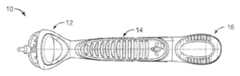
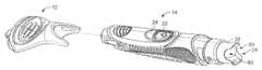
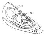
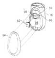
도 1을 참조하면, 면도기 손잡이(10)는 면도기 헤드(12), 그립 튜브(14) 및 전지 쉘(16)을 포함한다. 면도기 헤드(12)는 면도기 분야에서 잘 알려진 바와 같이 손잡이(10) 상에 교체가능한 면도기 카트리지(도시 안됨)를 장착하기 위한 연결 구조물을 포함한다. 그립 튜브(14)는 면도 중에 사용자에 의해 보유되도록, 그리고 면도기의 전지 구동 기능을 제공하는 면도기의 구성요소, 예컨대 진동을 발생시키도록 구성된 모터와 인쇄 회로 기판을 보유하도록 구성된다. 그립 튜브는 헤드(12)가 고정식으로 부착되는 밀봉된 유닛이어서, 모듈형 제조가 가능하며 이하 논의될 다른 이점을 제공한다. 도 3을 참조하면, 전지 쉘(16)은 그립 튜브(14)에 제거가능하게 부착되어, 사용자는 전지(18)를 교체하기 위하여 전지 쉘을 제거할 수 있다. 전지 쉘과 그립 튜브 사이의 경계면은 예컨대 O-링(20)에 의해 밀봉되어, 면도기 내의 전지와 전자장치를 보호하기 위한 수밀 조립체를 제공한다. O-링(20)은 일반적으로, 예컨대 억지 끼워맞춤에 의해 그립 튜브 상의 홈(21)(도 5) 내에 장착된다. 다시 도 1을 참조하면, 그립 튜브(14)는 전자 스위치(29)(도 7a)를 통해 면도기의 전지 구동 기능을 작동시키기 위하여 사용자에 의해 눌려질 수 있는 액추에이터 버튼(22)을 포함한다. 그립 튜브는 또한 사용자에게 전지 상태 및/또는 기타 정보에 대한 시각적 표시를 제공하는 발광체(31) 또는 디스플레이 또는 기타 시각적 표시기(도 7a), 예컨대 LED 또는 LCD를 사용자가 관찰할 수 있게 하는 투명 윈도우(24)를 포함한다. 발광체(31)는 투명 윈도우 아래에서 그립 튜브 내에 제공된 개구(45)(도 8)를 통해 빛을 낸다. 면도기 손잡이의 이들 및 다른 특징은 이하에서 더욱 상세하게 설명될 것이다.Referring to FIG. 1, the razor handle 10 includes a
모듈형 그립 튜브 구조Modular Grip Tube Structure
앞서 논의된 바와 같이, (도 4 및 도 5에 상세하게 도시된) 그립 튜브(14)는 면도기 헤드(12)가 고정식으로 부착되는 모듈형 조립체이다. 그립 튜브의 모듈성(modularity)은 유리하게는 단일 유형의 그립 튜브가 여러 상이한 면도기 헤드 종류와 함께 사용되도록 제조될 수 있게 한다. 이는 이어서 상이한 헤드를 구비하지만 동일한 전지 구동 기능을 갖는 제품들의 "군"의 제조를 단순화한다. 그립 튜브는 전지 쉘이 부착되는 단부의 개구(25)를 제외하고는 수밀형이며, 단일 일체형 부품인 것이 바람직하다. 따라서, 면도기 손잡이(10)의 수밀을 보장하는 데에 요구되는 유일한 밀봉체는 O-링(20)(도 3)에 의해 제공되는, 그립 튜브와 전지 쉘 사이의 밀봉체이다. 이러한 단일-밀봉체 구성은 물 또는 습기가 면도기 손잡이로 스며들어 전자장치를 손상시키는 위험을 최소화한다.As discussed above, the grip tube 14 (shown in detail in FIGS. 4 and 5) is a modular assembly to which the
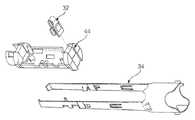
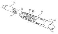
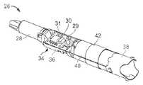
도 6에 도시된 바와 같이, 그립 튜브(14)는 진동 모터(28), 인쇄 회로 기판(30), 인쇄 회로 기판 상에 장착된 전자 스위치(29)와 발광체(31), 및 전자장치에 전지 전력을 제공하기 위한 양극(positive) 접촉부(32)를 포함하는 부조립체(26)(도 7c에도 도시됨)를 보유한다. 이들 구성요소는, 이하 전지 클램프 단락과 전지 쉘 부착 단락에서 그 기능이 논의될 전지 클램프 핑거(battery clamp finger)(36)와 수형 베이요닛부(male bayonet portion)(38)를 또한 포함하는 캐리어(34) 내에 조립된다. 면도기의 모든 기능적 전자 구성요소를 캐리어(34) 상에 조립함으로써 전지 구동 기능이 사전에 시험될 수 있으므로 고장이 조기에 검출될 수 있으며, 완성된 면도기의 폐기에 따른 고가의 비용을 최소화한다. 부조립체(26)는 또한, 이하 전지 클램프 단락에서 그 기능이 논의될 절연 슬리브(40)와 장착 테이프(42)를 포함한다.As shown in FIG. 6, the
부조립체(26)는 도 7 내지 도 7c에 도시된 바와 같이 조립된다. 먼저, 양극 접촉부(32)가 PCB 캐리어(44) 상에 조립되며, 이는 이어서 캐리어(34) 상에 장착된다(도 7). 다음으로, 인쇄 회로 기판(30)이 PCB 캐리어(44) 내에 배치되고(도 7a), 진동 모터(28)가 캐리어(34) 상에 장착되며(도 7b), 이때 리드 와이어(46)가 인쇄 회로 기판 상에 납땜되어 부조립체(26)가 완성된다(도 7c). 그 후, 부조립체는 그립 튜브 내로 조립되기 전에 시험될 수 있다.
부조립체(26)는 그립 튜브 내로 영구적으로 그 내부에 보유되도록 조립된다. 예를 들면, 부조립체(26)는 그립 튜브의 내벽의 대응 리세스와 억지 끼워맞춤으로 결합하는 돌출부 또는 아암을 포함할 수 있다.The
그립 튜브는 또한 액추에이터 버튼(22)을 포함한다. 강성(rigid) 액추에이터 버튼이 앞서 논의된 윈도우(24)를 포함하는 수용 부재(48)(도 8) 상에 장착된다. 수용 부재(48)는 액추에이터 부재(52)를 지지하는 외팔보형 비임(50)을 포함한다. 액추에이터 부재(52)는 버튼(22)에 가해진 힘을 하부에 놓인 탄성 멤브레인(54)(도 8)으로 전달한다. 멤브레인(54)은 멤브레인뿐만 아니라 탄성중합체 그립부를 형성하기 위하여 그립 튜브 상으로 성형되는, 예컨대 탄성중합체 재료일 수 있다. 외팔보형 비임은 멤브레인과 협력 작용하여 사용자에 의해 눌려진 후 버튼(22)을 그의 정상 위치로 복귀시키기 위한 복원력을 제공한다. 버튼이 눌려진 때, 액추에이터 부재(52)는 하부에 놓인 전자 스위치(29)와 접촉하며, 이는 PCB(30)의 회로를 작동시킨다. 작동은 "누름 및 해제" 온/오프(on/off) 동작식으로 또는 다른 원하는 동작식으로, 예컨대 누름 온/누름 오프식으로 이루어질 수 있다. 전자 스위치(29)는 작동된 때 가청 "클릭음"을 발생시켜서, 장치가 올바르게 켜졌음에 대한 사용자 피드백을 제공한다. 스위치는 짧은 거리에 걸쳐 비교적 큰 작동력이 가해질 것(예컨대, 약 0.25 ㎜ 변위에 걸쳐 4 N 이상이 가해질 것)을 필요로 하도록 구성되는 것이 바람직하다. 이러한 스위치 장치는 버튼(22)의 리세스된 저 프로파일(low profile)의 기하학적 형상과 조합되어, 면도기가 여행 중에 우연하게 켜지거나 면도 중에 부주의하게 꺼지는 것을 방지하기 쉽다. 더욱이, 스위치/멤브레인/액추에이터 부재 조립체의 구조는 사용자에게 양호한 촉각적 피드백을 제공한다. 액추에이터 부재(52)는 또한 버튼(22)을 정위치로 유지하여, 액추에이터 부재(52)의 중앙의 개구부(55)가 버튼(22) 밑면 상의 돌출부(56)를 수용하게 된다(도 8b).The grip tube also includes an
투명 윈도우(24)는 버튼(22)에 인접해 있어서, 사용자는 이를 통해 하부에 놓인 발광체에 의해 제공되는 표시를 식별할 수 있으며, 이는 이하 전자장치 단락에서 상세하게 설명된다.The
윈도우(24) 및 액추에이터 버튼의 그립 튜브 상에의 조립은 도 8 내지 도 8d에 도시되어 있다. 먼저, 윈도우(24)를 지지하는 수용 부재(48)가 앞서 논의된 일체형 수밀 부품을 형성하도록, 예컨대 접착 또는 초음파 또는 열 용접에 의해 그립 튜브 상에 밀봉식으로 장착된다(도 8). 다음으로, 버튼(22)이 정위치로 살짝 넣어지고 수용 부재 내의 개구 내로 (바람직하게는 10 N 미만의 힘으로) 서서히 밀어내려 져서, 돌출부(56)가 개구부(55)와 결합하게 된다(도 8a 내지 도 8c).Assembly of the
전지 쉘 부착With battery shell
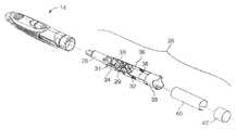
앞서 논의된 바와 같이, 전지 쉘(16)은 그립 튜브(14)에 제거가능하게 부착되어, 전지가 제거 및 교체될 수 있다. 손잡이의 2개의 부품이 연결되고, 전지의 음극 단자와 전자 구성요소 사이의 전기 접촉이 베이요닛 연결부에 의해 수립된다. 그립 튜브는 베이요닛 연결부의 수형부를 보유하는 반면, 전지 쉘은 암형부를 보유한다. 조립된 베이요닛 연결부가 명확함을 위하여 그립 튜브와 전지 쉘이 생략된 상태로 도 9, 도 9a 및 도 10에 도시되어 있다.As discussed above, the
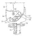
앞서 논의된 캐리어(34)의 수형 베이요닛부(38)는 베이요닛 연결부의 수형부를 제공한다. 수형 베이요닛부(38)는 한 쌍의 돌출부(60)를 보유한다. 이들 돌출부는 전지 쉘에 의해 보유되는 암형 베이요닛 구성요소(64)의 대응 슬롯(62) 내에 수용되어 유지되도록 구성된다. 각각의 슬롯(62)은 전지 쉘이 그립 튜브에 대해 회전됨에 따라 각각의 돌출부를 대응 슬롯 내로 안내하도록 경사진 벽(66, 68)(도 9a)을 갖는 도입부(lead-in)를 포함한다. 멈춤 구역(65)(도 9a)이 각각의 슬롯(62)의 단부에 제공된다. 멈춤 구역(65) 내에서의 돌출부의 결합(도 9b)은 그립 튜브에 대한 전지 쉘의 견고한 트위스트-온(twist-on) 방식의 기계적 연결을 제공한다.The
캐리어(34)와 암형 베이요닛 구성요소(64)는 모두 금속으로 제조되며, 따라서 슬롯과의 돌출부의 결합은 또한 캐리어와 암형 베이요닛 구성요소 사이의 전기 접촉을 제공한다. 캐리어는 이어서 장치의 회로와 전기 접촉하게 되고, 전지의 음극 단자는 암형 베이요닛 구성요소와 전기적으로 통신하는 전지 스프링(70)(도 9a)과 접촉하게 되며, 따라서 스프링 부재와 전기 부품의 접촉은 궁극적으로 전지와 장치의 회로 사이의 접촉이 된다.The
도 12에 도시된 바와 같이, 전지 스프링(70)은 스프링 홀더(72) 상에 장착되며, 이는 이어서 전지 쉘(16)의 내벽에 고정식으로 장착된다. 암형 베이요닛 구성요소(64)는 전지 쉘(16) 내에서 축방향 전후로 자유롭게 활주한다. 그의 휴지 위치(rest position)에서, 암형 베이요닛 구성요소는 베이요닛 스프링(74)에 의해 전지 쉘의 기부로 편의된다. 베이요닛 스프링(74)은 역시 스프링 홀더(72) 상에 장착되며, 따라서 그 상단부는 전지 쉘의 내벽에 대하여 고정식으로 장착된다. 전지 쉘이 그립 튜브 상으로 비틀려 들어갈 때, 암형 베이요닛 구성요소 상의 경사진 슬롯과의 수형 베이요닛 구성요소 상의 돌출부의 결합은 암형 베이요닛 구성요소를 전방으로 당기게 되어, 베이요닛 스프링(74)이 압축된다. 그러면, 베이요닛 스프링의 편의력에 의해 암형 베이요닛 구성요소는 수형 베이요닛 구성요소 및 그에 따른 그립 튜브를 전지 쉘을 향해 당기게 된다. 결과적으로, 손잡이의 2개의 부품 사이의 모든 간극이 스프링력에 의해 메워지며, O-링이 압축되어 수밀 밀봉 결합을 제공한다. 결합이 완성된 때, 돌출부(60)는 암형 베이요닛 슬롯(62)의 대응 V형 멈춤 구역(65) 내에 수용된다(도 9b). 이는 명확한 가청 클릭음으로서 사용자에게 인지되어, 전지 쉘이 올바르게 결합되었음에 대한 명확한 표시를 제공한다. 이러한 클릭음은 돌출부가 V형 멈춤 구역(65) 내로 신속하게 활주되게 하는 베이요닛 스프링의 작용의 결과이다.As shown in FIG. 12, the
그립 튜브와의 전지 쉘의 이러한 탄성 결합은 전지 쉘과 그립 튜브 사이의 비선형 시임선(seam line) 및 공차와 같은 기타 기하학적 문제를 보상한다. 베이요닛 스프링에 의해 가해진 힘은 또한 수형 및 암형 베이요닛 구성요소들 사이의 견고하고 신뢰성 있는 전기 접촉을 제공한다.This elastic coupling of the battery shell with the grip tube compensates for other geometric problems such as nonlinear seam and tolerances between the battery shell and the grip tube. The force exerted by the bayonet spring also provides a robust and reliable electrical contact between the male and female bayonet components.
스프링 장착식 암형 베이요닛 구성요소는 또한 전지 쉘이 부착되고 제거될 때 수형 및 암형 베이요닛 구성요소에 작용하는 힘을 제한한다. 그립 튜브와 전지 쉘이 서로 접촉한 후에 사용자가 전지 쉘을 계속 회전시키는 경우, 암형 베이요닛 구성요소는 전지 쉘 내에서 약간 전방으로 이동될 수 있어서, 수형 베이요닛 구성요소의 돌출부에 의해 가해지는 힘을 감소시킨다. 따라서, 힘은 비교적 일정하게 그리고 미리설정된 범위 내에서 유지된다. 이러한 특징은 사용자에 의한 험한 취급 또는 큰 부품 또는 조립 공차에 기인하여 부품이 손상되는 것을 방지할 수 있다.The spring loaded female bayonet component also limits the forces acting on the male and female bayonet components when the battery shell is attached and removed. If the user continues to rotate the battery shell after the grip tube and the battery shell are in contact with each other, the female bayonet component may be moved slightly forward within the battery shell, so that the force exerted by the protrusion of the male bayonet component Decreases. Thus, the force remains relatively constant and within a preset range. This feature can prevent parts from being damaged due to rough handling by the user or large parts or assembly tolerances.
전술한 바와 같은 탄성 결합을 달성하기 위하여, 베이요닛 스프링의 스프링력이 전지 스프링의 스프링력보다 큰 것이 일반적으로 중요하다. 일반적으로, 2개의 스프링의 바람직한 상대적 힘은 하기와 같이 계산될 수 있다:In order to achieve the elastic coupling as described above, it is generally important that the spring force of the bayonet spring is greater than the spring force of the battery spring. In general, the preferred relative force of the two springs can be calculated as follows:
1. 전지 스프링을 스프링에 의해 가해지는 접촉력(Fbatmin)이 최소 전지 길이에 대해 충분하도록 설계한다.1. Design the battery spring so that the contact force (Fbatmin) exerted by the spring is sufficient for the minimum cell length.
2. 최대 전지 길이에 대해 요구되는 전지 스프링력(Fbatmax)을 계산한다.2. Calculate the required battery spring force (Fbatmax) for the maximum cell length.
3. O-링의 마찰을 극복하기 위하여 그립 튜브에 대항하여 전지 쉘을 누르는 데에 요구되는 최대 힘(Fpmax)을 계산한다.3. Calculate the maximum force (Fpmax) required to press the battery shell against the grip tube to overcome the friction of the O-ring.
4. 폐쇄된 상태에서 그립 튜브에 대항하여 전지 쉘이 눌려져야 하는 최소 폐쇄력(Fclmin)을 결정한다.4. Determine the minimum closing force (Fclmin) at which the battery shell must be pressed against the grip tube in the closed position.
5. Fbayonet = Fbatmax + Fpmax + Fclmin에 따라 베이요닛 스프링에 의해 가해지는 힘을 계산한다.5. Calculate the force exerted by the bayonet spring according to Fbayonet = Fbatmax + Fpmax + Fclmin.
예로서, 몇몇 구현에서, Fbatmax = 4N, Fpmax = 2N, 그리고 Fclmin = 2N이면, Fbayonet = 8N이다.For example, in some implementations, if Fbatmax = 4N, Fpmax = 2N, and Fclmin = 2N, Fbayonet = 8N.
전지 클램프Battery clamp
앞서 논의된 바와 같이, 캐리어(34)는 한 쌍의 전지 클램프 핑거(36)(도 6 및 도 10)를 포함한다. 이들 핑거는 전지(18)(도 3)에 대항하여 작은 클램핑력을 가하는 2개의 스프링으로서 작용한다. 이러한 클램핑력은 전지가 그립 튜브의 내벽에 대항하여 또는 다른 부품에 대항하여 덜걱거리는 것을 방지하도록 충분하게 강하여, 사용 중에 면도기에 의해 발생되는 노이즈를 감소시킨다. 바람직하게는, 클램핑력은 또한 전지 쉘이 제거되고 그립 튜브가 전도된 때 전지를 떨어지지 않게 하도록 충분하게 강하다. 다른 한편, 클램핑력은 사용자가 전지를 쉽게 제거하여 교체할 수 있도록 충분하게 약해야 한다. 수형 베이요닛 구성요소(38)는 전지가 제거를 위하여 그를 통하여 사용자에 의해 파지될 수 있는 개방 구역(80)(도 4)을 포함한다.As discussed above, the
스프링 핑거의 치수와 그 스프링력은 일반적으로 스프링 핑거가 앞서 논의된 최소 크기 전지의 중량을 유지하고 면도기가 수직으로 유지된 때 떨어지는 것이 방지되며, 또한 동시에 최대 크기 전지가 그립 튜브로부터 쉽게 제거되게 하도록 조절된다. 이러한 제약을 만족시키기 위하여, 몇몇 구현예에서, 전지와 포일 사이의 마찰 계수가 약 0.15 내지 0.30인 상태에서, 하나의 핑거에 대한 스프링력이 (예컨대, 직경이 9.5㎜인) 최소 크기 전지가 삽입된 때 약 0.5N이고, (예컨대, 직경이 10.5㎜인) 최대 크기 전지가 삽입된 때 약 2.5N 미만인 것이 바람직하다. 일반적으로, 면도기가 전지 개구를 하향으로 지향시킨 상태로 유지된 때, 최소 크기 전지가 떨어지지 않을 것이며 최대 크기 전지가 쉽게 꺼내질 수 있다면, 스프링 핑거는 전술한 기능을 수행할 것이다.The dimensions of the spring fingers and their spring forces are generally such that the spring fingers maintain the weight of the minimum size cells discussed above and are prevented from falling when the razor is held vertically, while at the same time allowing the full size cells to be easily removed from the grip tube Adjusted. In order to satisfy this constraint, in some embodiments, with a coefficient of friction between the cell and the foil being about 0.15 to 0.30, a minimum size cell (eg, 9.5 mm in diameter) with a spring force for one finger is inserted. Preferably about 0.5 N when the full size cell (eg, 10.5 mm in diameter) is inserted and less than about 2.5 N. In general, when the razor is held with the cell opening facing downward, the spring finger will perform the function described above if the minimum size cell will not fall and the maximum size cell can be easily taken out.
도 6 및 도 7c를 참조하면, 예컨대 플라스틱 포일의 얇은 절연 슬리브(40)가 진동 노이즈를 추가로 감쇠시키며, 전지 표면이 손상된 경우의 회로 단락에 대항하는 안전성을 제공한다. 도 7c에 도시된 바와 같이, 슬리브(40)는 전지가 제거되어 교체될 때 슬리브를 정위치로 유지하기 위하여 테이프(42)에 의해 전지 클램프 핑거에 고정된다. 절연 슬리브용의 적합한 재료는 두께가 약 0.06㎜인 폴리에틸렌 테레프탈레이트(PET) 필름이다.6 and 7C, for example, a thin insulating
전지함의 통기Aeration of the battery box
소정의 조건 하에서, 수소는 전지 구동형 기구의 내부에 축적될 수 있다. 수소는 전지로부터 방출될 수도 있고, 또는 전지 외부에서 전기 분해에 의해 생성될 수도 있다. 이 수소가 주변 산소와 혼합됨으로써 폭발성 가스가 형성될 수 있는데, 이 가스는 장치의 모터 또는 스위치로부터의 스파크(spark)에 의해 잠재적으로 발화될 수 있다. 그러므로, 수밀을 계속 유지하는 상태에서 모든 수소가 면도기 손잡이로부터 배출되어야 한다.Under certain conditions, hydrogen can accumulate inside the battery powered mechanism. Hydrogen may be released from the cell or may be produced by electrolysis outside the cell. This hydrogen can be mixed with ambient oxygen to form an explosive gas, which can potentially be ignited by sparks from the motor or switch of the device. Therefore, all hydrogen must be discharged from the razor handle while maintaining watertightness.
도 13을 참조하면, 통기 구멍(90)이 전지 쉘(16) 내에 제공된다. 가스 투과성이지만 액체에 대해서는 불투과성인 미공성 멤브레인(92)이 통기 구멍(90)을 덮도록 전지 쉘(16)에 용접된다. 적합한 멤브레인 재료는 고어(GORE)로부터 구매가능한 폴리테트라플루오로에틸렌(PTFE)이다. 바람직한 멤브레인은 두께가 약 0.2㎜이다. 멤브레인은 방수도(water-proofness)가 70㎪ 이상이고 공기 투과도가 10 ㎪(100 mbar)의 과압(overpressure)에서 12ℓ/hr/㎠ 이상인 것이 일반적으로 바람직하다.Referring to FIG. 13, a vent hole 90 is provided in the
미공성 멤브레인의 이점은 멤브레인의 양면 상의 수소의 분압 차이에 기인한 확산에 의해 수소가 배출될 것이라는 점이다. 배출을 일으키기 위한 면도기 손잡이 내에서의 전압의 증가는 요구되지 않는다.The advantage of the microporous membrane is that hydrogen will be released by diffusion due to the differential partial pressure of hydrogen on both sides of the membrane. No increase in voltage in the razor handle to cause drainage is required.
사용자에게 통기 구멍과 멤브레인이 보이는 것은 미적인 관점에서 바람직하지 않다. 더욱이, 멤브레인이 노출되어 있다면, 멤브레인의 기공이 막히게 될 것이고 그리고/또는 멤브레인이 손상되거나 제거될 것이라는 위험성이 존재한다. 멤브레인을 보호하기 위하여, 덮개(94)가 예컨대 접착에 의해 멤브레인/통기 구역 위에서 전지 쉘에 부착된다. 가스가 덮개(94)의 아래로부터 방출될 수 있도록, 덮개의 내부 표면과 전지 쉘(16)의 외부 표면(98) 사이에 개방 구역이 제공된다. 도면에 도시된 구현예에서, 복수의 리브(96)가 통기 구멍(90)에 인접하게 전지 쉘 상에 제공되어, 덮개와 전지 쉘 사이의 공기 채널을 생성한다. 그러나, 필요한 경우 통기 공간을 생성하기 위하여 다른 구조가 사용될 수 있는데, 예컨대 덮개 및/또는 그립 튜브가 단일 채널을 형성하는 함몰된 홈을 포함할 수도 있으며 리브가 생략될 수도 있다.It is not desirable from the aesthetic point of view that vent holes and membranes are visible to the user. Moreover, if the membrane is exposed, there is a risk that the pores of the membrane will be blocked and / or the membrane will be damaged or removed. In order to protect the membrane, a
공기 채널의 높이와 폭은 안전한 정도의 통기를 제공하도록 선택된다. (도시 안된) 일례에서, 통기 구멍의 각각의 측면 상에 하나의 채널이 존재할 수 있으며, 각각의 채널은 높이가 0.15㎜이고 폭이 1.1㎜이다.The height and width of the air channel are chosen to provide a safe degree of ventilation. In one example (not shown), there may be one channel on each side of the vent, each channel being 0.15 mm high and 1.1 mm wide.
덮개(94)는 장식될 수도 있다. 예를 들면, 덮개는 로고 또는 기타 장식물을 보유할 수도 있다. 덮개(94)는 또한 촉각적 그립 표면 또는 기타 인간공학적 특징을 제공할 수도 있다.The
전자장치Electronics
가변 속도 제어Variable speed control
전기 면도기는 흔히 신체 상의 여러 위치에서 상이한 유형의 모발을 면도하는 데에 사용된다. 이들 모발은 현저하게 상이한 특징을 갖는다. 예를 들면, 수염(whisker)은 다리털보다 두꺼운 경향이 있다. 이들 모발은 또한 피부로부터 상이한 각도로 돌출한다. 예를 들면, 짧은 수염(stubble)은 주로 피부에 대해 직각이지만, 다리털은 보다 편평하게 눕는 경향이 있다.Electric shavers are often used to shave different types of hair at different locations on the body. These hairs have markedly different characteristics. For example, whiskers tend to be thicker than leg hair. These hairs also protrude from the skin at different angles. For example, short stubs are usually perpendicular to the skin, but leg hair tends to lie flatter.
이들 모발을 면도할 수 있게 하는 용이성은 카트리지가 진동하는 주파수에 부분적으로 좌우된다. 이들 모발은 상이한 특징을 갖기 때문에, 상이한 진동 주파수가 상이한 유형의 모발에 대하여 최적화될 수 있음은 당연하다. 그러므로, 사용자에게 이러한 진동 주파수를 제어하는 방식을 제공하는 것이 유용하다.The ease of shaving these hairs depends in part on the frequency at which the cartridge vibrates. Since these hairs have different characteristics, it is natural that different vibration frequencies can be optimized for different types of hair. Therefore, it is useful to provide a way for the user to control this vibration frequency.
도 14a에 도시된 바와 같이, 면도 카트리지의 진동 주파수는 제어 논리부(105)의 제어 하에서 듀티 사이클(duty cycle)을 갖는 펄스폭 변조기(301)에 의해 제어된다. 본 명세서에 사용되는 바와 같이, "듀티 사이클"은 펄스의 시간 길이와 펄스들 간의 일시정지(pause)의 시간 길이 사이의 비를 의미한다. 그러므로, 낮은 듀티 사이클은 펄스들 간의 대기 시간이 긴 짧은 펄스를 특징으로 하며, 반면에 높은 듀티 사이클은 펄스들 간의 대기 시간이 짧은 긴 펄스를 특징으로 한다. 듀티 사이클을 변화시킴으로써 모터(306)의 속도가 변화하며, 이는 이어서 면도 카트리지의 진동 주파수를 조절하게 된다.As shown in FIG. 14A, the vibration frequency of the shaving cartridge is controlled by a
제어 논리부(105)는 마이크로컨트롤러 또는 기타 마이크로프로세서 기반 시스템으로 구현될 수 있다. 제어 논리부는 또한 응용 주문형 집적 회로(application-specific integrated circuit, "ASIC")로 또는 현장 프로그램가능 게이트 어레이(field-programmable gate array, "FPGA")로서 구현될 수 있다.The
모터(306)는 면도 카트리지의 운동을 발생시키는 임의의 에너지 소비 장치일 수 있다. 모터(306)의 하나의 구현예는 소형 고정자 및 면도 카트리지에 결합되는 회전자를 포함한다. 모터(306)의 다른 구현예는 면도 카트리지에 결합되는 압전 소자(piezoelectric device)를 포함한다. 또는, 모터(306)는 진동 자기장에 의해 면도 카트리지에 자기적으로 결합되는 장치로서 구현될 수 있다.
가변 속도 제어되는 면도기에서, 제어 논리부(105)는 속도 제어 스위치(304)로부터 입력 속도 제어 신호(302)를 수신한다. 속도 제어 신호(302)에 응답하여, 제어 논리부(105)는 펄스폭 변조기(301)가 그 듀티 사이클을 변화시키게 한다. 이는 이어서 모터 속도가 변화되게 한다. 그러므로, 펄스폭 변조기(301)는 속도 컨트롤러로서 고려될 수 있다.In the variable speed controlled shaver, the
속도 제어 스위치(304)는 다양한 방식으로 구현될 수 있다. 예를 들면, 속도 제어 스위치는 연속적으로 움직일 수 있다. 이러한 경우, 사용자는 연속되는 속도로부터 선택할 수 있다. 또는, 속도 제어 스위치(304)는 불연속적인 정지부를 가질 수 있어서, 사용자는 일 세트의 미리한정된 모터 속도로부터 선택할 수 있다.The
속도 제어 스위치(304)는 다양한 형태를 취할 수 있다. 예를 들면, 스위치(304)는 연속적으로 또는 불연속적인 단계들 사이에서 움직이는 노브(knob) 또는 슬라이더(slider)일 수 있다. 스위치(304)는 또한 각각이 상이한 속도에 할당된 일 세트의 버튼일 수 있다.The
또는, 스위치(304)는 하나의 버튼이 속도를 증가시키도록 할당되며 다른 하나가 속도를 감소시키도록 할당된 한 쌍의 버튼일 수 있다. 또는, 스위치(304)는 연속적으로 또는 불연속적으로 여러 속도를 통과하여 순환하도록 눌려지는 단일 버튼일 수 있다.Alternatively, switch 304 may be a pair of buttons, one button assigned to increase speed and the other assigned to reduce speed. Alternatively, the
다른 유형의 스위치(304)는 스프링 장착식 트리거(trigger)이다. 이러한 유형의 스위치는, 사용자가 트리거를 잡아당김으로써 체인소(chain saw)의 속도를 연속적으로 변화시킬 수 있는 것과 동일한 방식으로, 사용자가 면도하면서 진동 주파수를 연속적으로 변화시킬 수 있게 한다.Another type of
액추에이터 버튼(22)이 또한 제어 논리부(105)를 적합하게 프로그래밍함으로써 속도 제어 스위치(304)로서 기능하도록 눌려질 수 있다. 예를 들면, 액추에이터 버튼(22)의 더블 클릭 또는 길게 누름이 모터 속도를 변화시키는 명령으로서 간주되도록 제어 논리부(105)를 프로그래밍할 수 있다.
이용가능한 속도 중에서 하나의 속도는 면도기의 세정에 최적화된다. 이러한 속도의 예는 가능한 최고 진동 주파수이며, 이는 제어 논리부(105)가 듀티 사이클을 가능한 한 높여 구동되게 함으로써 달성된다. 대안적으로, 제어 논리부(105)는 모터(306)가 소정 범위의 진동 주파수를 통해 세척하게 하는 세정 모드로 동작시킬 수 있다. 이는 모터(306)가 면도날, 카트리지, 및 임의의 오염 입자, 예컨대 면도된 수염 파편과 관련하여 상이한 기계적 공진 주파수로 자극할 수 있게 한다. 세정 모드는 소정 주파수 범위에 걸친 연속적 세척으로서, 또는 제어 논리부(105)가 모터(306)를 수개의 불연속적인 주파수를 통해 단계를 나누어 각각의 이러한 주파수에서 순간적으로 일시정지하게 하는 단계식 세척으로서 구현될 수 있다.One of the available speeds is optimized for cleaning the shaver. An example of this speed is the highest possible oscillation frequency, which is achieved by having the
몇몇 경우에서, 면도기가 하나 이상의 바람직한 진동 주파수를 기억할 수 있는 것이 유용하다. 이는 도 14b에 도시된 바와 같이 제어 논리부(105)와 통신하는 메모리를 제공함으로써 달성된다. 이러한 특징을 사용하기 위하여, 사용자는 속도를 선택하고, 별도의 제어에 의해 또는 미리한정된 순서에 따라 액추에이터 버튼(22)을 누름으로써 메모리 신호가 전송되게 한다. 그 후, 사용자는 이러한 기억된 속도를 필요로 할 때, 별도의 제어를 사용하여 또는 미리한정된 순서에 따라 액추에이터 버튼(22)을 누름으로써 다시 호출할 수 있다.In some cases it is useful for the razor to be able to remember one or more desirable vibration frequencies. This is accomplished by providing a memory in communication with the
도 14a 및 도 14b에 도시된 바와 같이, 면도기는, 액추에이터 버튼(22)이 펄스폭 변조기(301)를 동작시키는 제어 논리부(105)를 통해 간접적으로 모터(306)를 제어하는 간접 스위칭 시스템(indirect switching system)을 특징으로 한다. 그러므로, 스위치의 상태가 모터(306)의 상태를 직접 기억하는 순수한 기계적인 스위칭 시스템과 달리, 간접 스위칭 시스템은 모터(306)의 상태를 제어 논리부(105) 내에 기억한다.As shown in FIGS. 14A and 14B, the shaver includes an indirect switching system in which the
액추에이터 버튼(22)은 모터(306)의 상태를 더이상 기계적으로 기억할 필요가 없기 때문에, 간접 스위칭 시스템은 액추에이터 버튼(22)의 선택 및 배치에 있어서 더 큰 유연성을 제공한다. 예를 들면, 본 명세서에 개시된 바와 같은 간접 스위칭 시스템을 구비한 면도기는 명확한 촉각적 피드백과 더 짧은 이동 거리의 이점을 조합하는 인간공학적 버튼을 사용할 수 있다. 이러한 버튼은 이들의 더 짧은 이동 거리에 의해 습기 침투에 대항하여 더욱 쉽게 밀봉된다.Since the
간접 스위칭 시스템의 다른 이점은 제어 논리부(105)가 작동 패턴을 해석하도록 그리고 이 패턴에 기초하여 사용자의 의도를 추론하도록 프로그래밍될 수 있다는 점이다. 이는 모터(306)의 속도 제어와 관련하여 앞서 이미 논의되었다. 그러나, 제어 논리부(105)는 또한 액추에이터 버튼(22)의 비정상적 동작을 검출하고 이를 무시하도록 프로그래밍될 수 있다. 그러므로, 예컨대 면도하는 동안 의도하지 않게 일어날 수도 있는 액추에이터 버튼(22)의 통상적이지 않은 긴 누름은 무시될 것이다. 이러한 특징은 모터(306)를 우연하게 끄는 것과 관련된 성가심을 방지한다.Another advantage of the indirect switching system is that the
전압 컨트롤러Voltage controller
면도기의 유효성은 전지(316)에 의해 제공되는 전압에 부분적으로 좌우된다. 통상의 모터식 습식 면도기에서, 최적 전압 또는 전압 범위가 존재한다. 전지 전압이 최적 전압 범위를 벗어나면, 면도기의 유효성은 손상된다.The effectiveness of the shaver depends in part on the voltage provided by the
이러한 문제를 극복하기 위하여, 면도기는 전지(316)의 전압을 모터(306)가 실제 나타내는 전압과 구분하는, 도 14c에 도시된 간접 전원 장치를 특징으로 한다. 모터(306)가 실제 나타내는 전압은, 전지 전압을 모니터링하고 전지 전압의 측정에 응답하여 궁극적으로는 전지 전압의 변화를 보상하는 각종 장치를 제어하는 제어 논리부(105)에 의해 제어된다. 이는 본질적으로 모터(306)가 일정한 전압을 나타내게 한다.To overcome this problem, the shaver is characterized by the indirect power supply shown in FIG. 14C, which distinguishes the voltage of the
모터(306)가 나타내는 전압을 제어하기 위한 본 명세서에 설명된 방법과 시스템은 임의의 에너지 소비 부하에 적용될 수 있다. 이러한 이유로, 도 14c는 일반화된 부하(306)를 참조한다.The methods and systems described herein for controlling the voltage represented by the
일 실시예에서, 모터(306)는 공칭 전지 전압보다 낮은 동작 전압에서 동작하도록 설계된다. 결과적으로, 새로운 전지(316)가 삽입된 때, 전지 전압은 너무 높으므로 감소시켜야 한다. 감소 크기는, 최종적으로 감소가 필요하지 않을 때까지 전지(316)가 소모됨에 따라 줄어든다.In one embodiment, the
전압 감소는 전지(316)와 전기적으로 통신하는 전압 모니터(312)를 제공함으로써 쉽게 수행된다. 전압 모니터(312)는 측정된 전지 전압을 제어 논리부(105)로 출력한다. 이에 응답하여, 제어 논리부(105)는 모터(306)가 나타내는 전압을 일정하게 유지하도록 펄스폭 변조기(301)의 듀티 사이클을 변경한다. 예를 들면, 전지 전압이 1.5볼트로 측정되고 모터(306)가 1볼트에서 동작하도록 설계된 경우, 제어 논리부(105)는 듀티 사이클 비를 75%로 설정할 것이다. 이는 펄스폭 변조기(301)로부터의 출력 전압이 모터의 동작 전압과 평균적으로 일치되게 할 것이다.Voltage reduction is easily accomplished by providing a
대부분의 경우에서, 듀티 사이클은 전지 전압의 비선형 함수이다. 이러한 경우, 제어 논리부(105)는 비선형 함수를 사용하는 계산을 수행하거나, 또는 정확한 듀티 사이클을 결정하기 위한 조회 테이블(look-up table)을 사용하도록 구성된다. 대안적으로, 제어 논리부(105)는 펄스폭 변조기(301)의 출력으로부터 전압 측정치를 얻고 그 측정치를 출력 전압의 피드백 제어를 제공하도록 사용할 수 있다.In most cases, the duty cycle is a nonlinear function of the cell voltage. In this case, the
다른 실시예에서, 모터(306)는 공칭 전지 전압보다 높은 동작 전압에서 동작하도록 설계된다. 이 경우, 전지 전압은 전지(316)가 소모되는 양을 증가시킴으로써 높아진다. 이러한 제 2 실시예는 제어 논리부(105)에 의해 제어되는 전압 변환기(314)와 함께 전술한 바와 같은 전압 모니터(312)를 특징으로 한다. 적합한 전압 변환기(314)는 이하에서 상세히 설명된다.In another embodiment, the
제 3 실시예는 하나의 장치 내에 전술한 두 실시예 모두를 조합한다. 이러한 경우, 제어 논리부(105)는 측정된 전지 전압이 모터 동작 전압을 초과한 때 출력 전압을 감소시키기 시작한다. 그 후, 측정된 전지 전압이 모터 동작 전압보다 낮게 떨어진 때, 제어 논리부(105)는 듀티 사이클을 고정하고 전압 변환기(312)를 제어하기 시작한다.The third embodiment combines both of the foregoing embodiments in one device. In this case, the
통상의 전기 면도기에서, 모터 속도는 전지(316)가 소모됨에 따라 점진적으로 감소한다. 이러한 점진적인 감소는 전지(316)를 교체하라는 충분한 경고를 사용자에게 제공한다. 그러나, 간접 전원 장치를 구비한 전기 면도기에서, 이러한 경고는 존재하지 않는다. 전지 전압이 소정의 하한 임계치보다 낮게 떨어지면, 모터 속도는 아마도 면도 중일지라도 급격하게 감소한다.In a conventional electric shaver, the motor speed gradually decreases as the
이러한 불편함을 방지하기 위하여, 제어 논리부(105)는 전압 모니터(312)에 의해 제공되는 정보에 기초하여 저-전지 신호를 저-전지 표시기(414)에 제공한다. 저-전지 표시기(414)는 전압이 임계치보다 낮게 떨어진 때 켜지거나, 또는 반대로 전압이 임계치보다 높을 때에 켜진 채로 유지되고 임계치보다 낮게 떨어진 때 꺼지는, LED와 같은 단일 상태 출력 장치일 수 있다. 또는, 저-전지 표시기(414)는 전지(316)의 상태를 표시하는 그래픽 또는 숫자 디스플레이를 제공하는, 액정 디스플레이와 같은 다중 상태 장치일 수 있다.To prevent this inconvenience,
전압 모니터(312)는 또한 제어 논리부(105)와 함께 전지 전압이 심방전(deep-discharge) 임계치보다 낮게 떨어진 때 면도기의 동작을 완전하게 억제하도록 사용될 수 있다. 이러한 특징은 전지(316)의 심방전으로부터 초래될 수도 있는 전지 누출에 의해 야기되는 면도기에의 손상 가능성을 감소시킨다.The voltage monitor 312 can also be used with the
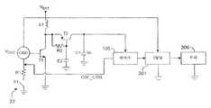
도 14d에 도시된 적합한 전압 변환기(312)는 오실레이터를 제어하는 스위치(S1)를 특징으로 한다. 이러한 스위치는 액추에이터 버튼(22)에 결합된다. 그러므로, 사용자가 액추에이터 버튼(22)을 누르면 오실레이터가 켜진다. 오실레이터 출력은 오실레이터의 제어 하에서 스위치로서 기능하는 트랜지스터(T1)의 게이트에 접속된다. 전지(316)는 전지 전압(VBAT)을 제공한다.
트랜지스터(T1)가 그의 전도 상태에 있을 때, 전류는 전지(316)로부터 인덕터(L1)를 통해 흐르고, 따라서 인덕터(L1) 내에 에너지가 저장된다. 트랜지스터가 그의 비전도 상태에 있을 때, 인덕터(L1)를 통해 전류가 계속 흐를 것이며, 이때에는 다이오드(D1)를 통해 흐르게 된다. 그 결과 전하가 다이오드(D1)를 통해 커패시터(C1)로 전달된다. 다이오드(D1)의 사용은 커패시터(C1)가 트랜지스터(T1)를 통해 접지로 방전되는 것을 방지한다. 그러므로, 오실레이터는 전하가 커패시터(C1)에 축적되는 것을 선택적으로 허용함으로써 커패시터(C1)를 가로지르는 전압을 제어하고, 그럼으로써 그 전압을 상승시킨다.When transistor T1 is in its conducting state, current flows from
도 14d에 도시된 회로에서, 오실레이터는 시변(time-varying) 전류가 인덕터(L1) 내에 존재하게 한다. 결과적으로, 오실레이터는 인덕터(L1)를 가로지르는 전압을 유도한다. 그 후, 이러한 유도 전압은 전지 전압에 부가되어, 최종 합계가 커패시터(C1)를 가로질러 이용될 수 있다. 이는 전지 단독으로 제공되는 전압보다 높은 커패시터(C1)에서의 출력 전압을 생성한다.In the circuit shown in FIG. 14D, the oscillator causes time-varying current to be present in the inductor L1. As a result, the oscillator induces a voltage across inductor L1. This induced voltage is then added to the cell voltage so that the final sum can be used across capacitor C1. This produces an output voltage at capacitor C1 that is higher than the voltage provided by the cell alone.
본질적으로 전압 변환기(312)의 출력 전압인 커패시터 전압은 제어 논리부(105) 및 최종적으로 모터(306)를 구동시키는 펄스폭 변조기(301) 모두로 접속된다. 커패시터 전압이 특정 임계치에 도달한 때, 제어 논리부(105)는 오실레이터로 접속되는 오실레이터 제어 신호 "osc_ctr"를 출력한다. 제어 논리부(105)는 오실레이터를 선택적으로 켜고 끄기 위하여 오실레이터 제어 신호를 사용하며, 그럼으로써 커패시터 전압 자체로부터의 피드백에 응답하여 커패시터 전압을 조정한다. 이러한 피드백 제어 시스템의 설정점, 즉 커패시터(C1)를 가로지르는 전압은 모터(306)가 일정한 동작 전압을 나타내도록 설정된다.The capacitor voltage, which is essentially the output voltage of the
오실레이터와 접지 사이에 배치된 레지스터(R1)가 스위치(S1)로부터 제어 논리부(105)로의 오실레이터의 제어를 선택적으로 전달하기 위한 디커플링 회로(decoupling circuit)의 일부로서 기능한다. 제어 논리부의 초기화에 앞서, 오실레이터 제어 신호를 전달하는 포트("오실레이터 제어 포트")가 고-임피던스 입력 포트로 설정된다. 결과적으로, 오실레이터의 동작을 제어하는 것은 스위치(S1)이다. 이러한 경우의 레지스터(R1)는 오실레이터 제어 포트로부터 접지로의 단락 회로를 방지한다. 초기화에 후속하여, 오실레이터 제어 포트는 저-임피던스 출력 포트가 된다.A resistor R1 disposed between the oscillator and ground functions as part of a decoupling circuit for selectively transferring control of the oscillator from the switch S1 to the
결국 사용자는 면도를 완료할 것이며, 이러한 경우에 그는 모터(306)를 끄길 원할 수 있다. 현재 오실레이터를 제어하고 있는 제어 논리부(105)에 의해서는, 전지(316)를 제거하지 않고서 면도기를 끌 수 없다. 이러한 문제를 방지하기 위하여, 외부 스위치(S1)의 상태를 주기적으로 결정하는 것이 유용하다. 이는 오실레이터 제어 포트가 주기적으로 고-임피던스 입력 포트가 되게 하여, 레지스터(R1)를 가로지르는 전압이 샘플링될 수 있도록 제어 논리부(105)를 구성함으로써 달성된다.Eventually the user will complete the shave, in which case he may want to turn off the
소정 유형의 스위치에서, 스위치의 상태는 사용자의 의도를 표시한다. 예를 들면, 폐쇄 위치의 스위치(S1)는 사용자가 모터(306)를 켜길 원한다는 것을 표시하며, 개방 위치의 스위치(S1)는 사용자가 모터(306)를 끄길 원한다는 것을 표시한다. 오실레이터 제어 포트가 다시 저-임피던스 출력 포트가 된 때 그와 같이 샘플링된 전압이 사용자가 스위치(S1)를 개방하였음을 표시할 경우, 제어 논리부(105)는 오실레이터 제어 신호가 오실레이터를 중지시키게 하고, 그럼으로써 모터(306)도 함께 중지된다. 이렇게 함에 있어서, 제어 논리부(105)는 또한 그 자신의 전원 장치를 중지시킨다.In certain types of switches, the state of the switch indicates the intention of the user. For example, switch S1 in the closed position indicates that the user wants to turn on the
다른 유형의 스위치에서, 스위치(S1)의 폐쇄는 단지 사용자가 모터의 상태를 온에서 오프로 또는 그 반대로 변경하길 원한다는 것을 표시한다. 이러한 스위치를 사용하는 실시예에서, 레지스터(R1)를 가로지르는 전압은 사용자가 스위치(S1)를 작동시킨 경우에 단지 잠시 동안 변경된다. 결과적으로, 제어 논리부(105)는 레지스터(R1)를 가로지르는 전압이 사용자의 순간적인 스위치(S1) 작동을 포착하는 것을 보장하도록 충분히 빈번하게 샘플링되게 한다.In other types of switches, the closing of the switch S1 merely indicates that the user wants to change the state of the motor from on to off or vice versa. In an embodiment using such a switch, the voltage across resistor R1 is only changed for a while when the user activates switch S1. As a result, the
도 14e는 오실레이터 제어 신호, 오실레이터 출력 및 커패시터 전압 사이의 상호작용을 도시한다. 커패시터 전압이 하한 임계치보다 낮게 떨어진 때, 오실레이터 제어 신호가 켜지고, 그럼으로써 오실레이터가 켜진다. 이에 의해 더 많은 전하가 커패시터(C1)에 축적되고, 이는 이어서 커패시터 전압을 상승시킨다. 커패시터 전압이 상한 임계치에 도달하면, 오실레이터 제어 신호가 꺼지고, 그럼으로써 오실레이터가 꺼진다. 전지(316)로부터 커패시터(C1)에 축적되는 전하가 더이상 없게 되면, 축적된 전하가 방출되기 시작하고 커패시터 전압이 감소되기 시작한다. 이는 다시 한번 하한 임계치에 도달할 때까지 이루어지며, 이 지점에서 전술한 사이클이 자체적으로 반복된다.14E illustrates the interaction between the oscillator control signal, the oscillator output, and the capacitor voltage. When the capacitor voltage falls below the lower threshold, the oscillator control signal turns on, thereby turning on the oscillator. This causes more charge to accumulate in the capacitor C1, which in turn raises the capacitor voltage. When the capacitor voltage reaches the upper threshold, the oscillator control signal is turned off, thereby turning off the oscillator. When there is no more charge accumulated in the capacitor C1 from the
도 14f에 도시된 전압 변환기(312)의 다른 실시예는, 다이오드(D1)가 RC 회로(R2 및 C2)에 의해 제어되는 게이트를 갖는 추가의 트랜지스터(T2)에 의해 교체된 것을 제외하면, 도 14d와 관련하여 설명된 것과 동일하다. 이러한 실시예에서, 오실레이터가 비활성 상태일 때, 추가 트랜지스터(T2)의 이미터(emitter)와 베이스(base) 사이의 전압(VBE2)은 0이다. 결과적으로, 추가 트랜지스터(T2)를 통한 전류 흐름은 중단된다. 이는 커패시터(C1)로부터 방출되는 전하를 대신하기 위하여 커패시터(C1)에 제공되는 전하가 없다는 것을 의미한다. 오실레이터가 활성 상태이고 오실레이터 주파수가 RC 회로의 컷-오프(cut-off) 주파수보다 높을 때, 이미터와 베이스 사이의 전압(VBE2)은 대략 전지 전압(VBAT)의 절반일 것이다. 결과적으로, 추가 트랜지스터(T2)는 전류를 커패시터(C1)로 통과시키는 한편 커패시터(C1)가 접지로 방전되는 것을 방지하는 다이오드로서 기능한다.Another embodiment of the
도 14f의 다른 주목할만한 특징은 펄스폭 변조기(301)에 전지(316)로부터 직접 전압이 공급된다는 것이다. 결과적으로, 펄스폭 변조기(301)의 출력 전압은 전지 전압보다 높을 수 없다. 그러므로, 도 14f에서, 모터(306)에는 낮아지는 전압이 공급되고, 반면에 커패시터(C1)를 가로지르는 전압인 높아지는 전압은 제어 논리부(105)에 공급되도록 사용된다. 그러나, 도 14f에 도시된 회로는 또한 도 14d에 도시된 바와 같이 커패시터(C1)를 가로지르는 전압으로부터 그의 입력을 취하는 펄스폭 변조기(316)를 특징으로 할 수 있다.Another notable feature of FIG. 14F is that voltage is supplied directly from
도 14g는 도 14f에 도시된 유형의 전압 변환기(312)를 구동하기 위한 회로를 더욱 상세하게 도시한다. 오실레이터는 접속이 제어 논리부(105)와 관련된 것으로 더욱 상세하게 도시되어 있다. 그러나, 도 14g에 도시된 회로는 다른 점에서는 도 14g에 도시된 바와 같이 변형된 도 14d와 관련하여 설명된 것과 본질적으로 동일하다.FIG. 14G shows a circuit in more detail for driving a
본 명세서에 설명된 바와 같이, 전압 제어 시스템은 모터(306)에 일정한 동작 전압을 제공한다. 그러나, 전기 면도기는 모터 이외의 부하를 포함할 수도 있다. 이들 부하 중 임의의 부하 또는 모든 부하는 본 명세서에 개시된 전압 제어 시스템에 의해 제공되는 일정한 동작 전압으로부터의 동일한 이점을 얻을 수 있다.As described herein, the voltage control system provides a constant operating voltage for the
일정한 동작 전압으로부터 이점을 얻을 수 있는 하나의 부하는 제어 논리부(105) 자체이다. 구매가능한 논리 회로(105)는 통상의 전지에서 이용할 수 있는 1.5 볼트보다 높은 전압에서 동작하도록 전형적으로 설계된다. 따라서, 제어 논리부에 높아지는 전압을 제공하는 전압 제어 시스템은 추가의 전지에 대한 필요성을 회피하는 데에 유용하다.One load that can benefit from a constant operating voltage is the
카트리지 수명 검출Cartridge Life Detection
매일 수백개의 수염을 통과하면서 자르는 과정에서, 면도기 카트리지의 면도날은 불가피하게 무뎌진다. 이러한 무뎌짐은 시각적 검사에 의해서는 검출하기 어렵다. 대개, 무딘 면도날은 너무 늦은 시기에만 검출된다. 너무 많은 경우에서, 면도날이 사용하기에는 너무 무디다는 것을 사용자가 인식하는 시기는 사용자가 이미 불쾌한 면도를 경험하기 시작한 때이다.In the process of cutting through hundreds of beards each day, the razor blades inevitably blunt. This bluntness is difficult to detect by visual inspection. Usually, blunt blades are detected only at too late. In too many cases, the time when the user realizes that the razor blade is too dull to use is when the user has already started experiencing an unpleasant shave.
무딘 면도날을 이용하는 이러한 최종 면도는 면도기에 의한 면도의 보다 불쾌한 측면들 중 하나이다. 그러나, 면도 카트리지의 비용으로 인해, 대부분의 사용자는 카트리지를 조기에 교체하는 것에 대해 당연히 내켜하지 않는다.This final shave using a blunt blade is one of the more unpleasant aspects of shaving with a razor. However, due to the cost of shaving cartridges, most users naturally do not insist on early replacement of the cartridge.
사용자가 언제 카트리지를 교체할지를 결정하는 것을 돕기 위하여, 면도기는 면도날이 이미 사용된 정도를 표시하는 계수값(count)을 유지하는 카운터(counter)(102)를 구비한, 도 15a에 도시된 면도날 수명 표시기(100)를 포함한다. 카운터는 손잡이(10) 상의 액추에이터 버튼(22) 및 면도기 헤드(12)의 말단부에 장착된 카트리지 검출기(104) 모두와 통신한다. 적합한 카운터(102)는 제어 논리부(105)로 구현될 수 있다.To help the user decide when to replace the cartridge, the razor has a counter blade life shown in FIG. 15A with a
카트리지 검출기(104)는 다양한 방식으로 구현될 수 있다. 예를 들면, 카트리지 검출기(104)는 카트리지 상의 대응 접촉부와 결합하도록 구성된 접촉부를 포함할 수 있다.The
면도기 카트리지는 1개, 2개 또는 2개 초과의 면도날을 포함할 수 있다. 본 설명 전체에 걸쳐, 단일 면도날을 참조한다. 그러나, 이 면도날은 카트리지 내의 임의의 면도날일 수 있으며, 모든 면도날은 마모된다는 것을 이해하여야 한다.The razor cartridge may comprise one, two or more than two razor blades. Throughout this description, reference is made to a single razor blade. However, it should be understood that this razor blade can be any razor blade in the cartridge, and that all razor blades wear out.
동작시, 사용자가 카트리지를 교체할 때, 카트리지 검출기(104)는 리셋(reset) 신호를 카운터(102)로 송신한다. 대안적으로, 리셋 신호는, 예컨대 사용자가 리셋 버튼을 누름으로써, 또는 사용자가 미리설정된 패턴에 따라 액추에이터 버튼을 누름으로써, 수동으로 발생될 수 있다. 이러한 리셋 신호는 카운터(102)가 그의 계수값을 리셋시키게 한다.In operation, when a user replaces a cartridge, the
카트리지를 검출하는 능력은 계수값을 리셋시키는 것 외의 용도에 사용될 수 있다. 예를 들면, 카트리지 검출기(104)는 올바른 카트리지가 사용되었는지, 또는 카트리지가 부적절하게 삽입되었는지를 결정하는 데에 사용될 수 있다. 제어 논리부(105)에 접속된 때, 카트리지 검출기(104)는 상태가 올바르게 될 때까지 모터를 동작하지 않게 할 수 있다.The ability to detect cartridges can be used for applications other than resetting count values. For example,
사용자가 면도할 때, 카운터(102)는 면도날의 추가 마모를 반영하도록 계수값의 상태를 변경한다. 카운터(102)가 계수값의 상태를 변경할 수 있는 방식은 다양하다.When the user shaves, the
도 15a에 도시된 구현예에서, 카운터(102)는 모터가 켜진 각각의 시점마다 계수값을 증가시킴으로써 계수값을 변경한다. 면도 간에 면도 시간이 작게 변하는 사용자의 경우, 이는 면도날 사용을 평가하기 위한 합리적이며 정확한 기준을 제공한다.In the implementation shown in FIG. 15A, the
몇몇 경우에서, 모터가 켜진 횟수는 면도날의 잔여 수명을 잘못 평가할 수도 있다. 이러한 오차는, 예컨대 사용자가 그의 다리를 면도하기 위하여 면도기를 "차용할" 때 발생한다. 이는 단지 모터의 단일 작동에 의한 상당한 면적의 면도로 이어진다.In some cases, the number of times the motor is turned on may misjudge the remaining life of the blade. This error occurs, for example, when the user "borrows" the shaver to shave his legs. This leads to a significant area shaving only by a single actuation of the motor.
전술한 문제는, 액추에이터 버튼(22)과 카운터(102)가 타이머(106)와 통신하는, 도 15b에 도시된 대안적인 구현예로 극복된다. 이러한 경우, 액추에이터 버튼(22)은 제어 논리부(105) 및 타이머(106) 모두로 신호를 송신한다. 결과적으로, 카운터(102)는 최종 카트리지 교체 이후의 누적 모터 동작 시간을 표시하는 계수값을 유지한다.The foregoing problem is overcome with the alternative implementation shown in FIG. 15B, in which the
누적 모터 동작 시간은 개선된 면도날 마모 표시기를 제공한다. 그러나, 대개, 면도날은 모터가 동작하는 모든 시간에서 피부와 접촉하지는 않는다. 따라서, 모터의 동작 시간에 기초한 평가는 면도날 마모를 과대 평가할 수밖에 없다. 또한, 모터 스위치는, 예컨대 면도기가 사용자의 짐 안에서 부딪칠 때 부주의하게 켜질 수도 있다. 이러한 상황 하에서는, 전지가 소모될 뿐만 아니라, 카운터(102)는 면도날이 아직은 개개의 수염을 면도해야 함에도 면도날이 마모된 것으로 표시할 것이다.Cumulative motor run time provides improved blade wear indicators. Usually, however, the blade does not come into contact with the skin at all times the motor is running. Therefore, evaluation based on the operating time of the motor has no choice but to overestimate the blade wear. In addition, the motor switch may be inadvertently turned on, for example when the razor is hit in the user's luggage. Under these circumstances, not only is the battery drained, but the
도 15c에 도시된 다른 구현예는 스트로크(stroke) 검출기(108)와 통신하는 카운터(102)를 포함한다. 이러한 경우, 액추에이터 버튼(22)은 스트로크 검출기(108) 및 제어 논리부(105) 모두로 신호를 송신한다. 그러므로, 모터를 켜게 되면 스트로크 검출기(108)가 역시 켜진다.Another implementation shown in FIG. 15C includes a
스트로크 검출기(108)는 면도날과 피부 사이의 접촉을 검출하며, 이러한 접촉의 검출시 카운터(102)로 신호를 송신한다. 이러한 방식으로, 스트로크 검출기(108)는 카운터(102)에 면도날이 실제 사용된다는 표시를 제공한다. 도 15c의 구현예에서, 카운터(102)는 카트리지가 최종 교체된 이후 면도날이 견딘 스트로크의 누적 횟수를 표시하는 계수값을 유지한다. 결과적으로, 카운터(102)는 모터가 동작하고 있지만 면도날이 실제로는 사용되지 않은 동안의 시간 간격은 무시한다.The
스트로크 검출기(108)에 대한 다양한 구현예가 이용될 수 있다. 몇몇 구현예는 피부 상의 또는 피부 부근의 전기적 특성과 자유 공간 내의 전기적 특성 사이의 변화에 의존한다. 예를 들면, 스트로크 검출기(108)는 피부 접촉과 관련된 저항, 인덕턴스 또는 커패시턴스의 변화를 측정함으로써 피부 접촉을 검출할 수 있다. 다른 구현예는 피부 상의 면도날 진동의 음향 지문(acoustic signature)과 자유 공간 내의 면도날 진동의 음향 지문 사이의 차이에 의존한다. 이들 구현예에서, 스트로크 검출기(108)는 2개의 지문 간을 구별하도록 구성된 신호 처리 장치에 연결된 마이크로폰을 포함할 수 있다. 또 다른 구현예는 면도날이 피부와 접촉한 때 모터의 동작 특성의 변화에 의존한다. 예를 들면, 피부 접촉과 관련된 증가된 부하로 인하여, 모터의 전류 소비가 증가할 수 있으며 모터의 속도가 감소할 수 있다. 이들 구현예는 전류계 또는 기타 전류 표시 장치 및/또는 속도 센서를 포함한다.Various implementations of the
그럼에도 불구하고 스트로크 횟수에 의존하는 평가는 모든 스트로크가 동일한 길이를 갖는 것은 아니기 때문에 부정확할 수 있다. 예를 들면, 다리를 따라 내려가는 스트로크는 콧수염을 면도하는 데에 필요한 수회의 스트로크보다 크게 면도날을 마모시킬 수 있다. 그러나, 이 스트로크 검출기(108)는 상이한 길이의 스트로크들 간의 차이를 알려줄 수는 없다.Nevertheless, the evaluation depending on the number of strokes may be inaccurate since not all strokes have the same length. For example, a stroke that descends along the leg may wear the blade greater than the few strokes needed to shave the mustache. However, this
도 15d에 도시된 다른 구현예는 액추에이터 버튼(22) 및 타이머(106) 모두와 통신하는 스트로크 검출기(108)를 포함한다. 타이머(106)는 카운터(102)와 통신한다. 역시, 액추에이터 버튼은 스트로크 검출기(108) 및 제어 논리부(105) 모두로 신호를 송신한다. 스트로크의 시작과 종료를 검출한 것에 각각 응답하여 스트로크 검출기(108)가 정지되고 타이머(106)가 개시된다. 이러한 구현예는, 이제 카운터(102)가 최종 카트리지 교체 이후에 카트리지가 피부와 접촉한 누적 시간("스트로크 시간"으로 지칭됨)을 표시하는 계수값을 유지한다는 것을 제외하고는, 도 15c의 구현예와 동일하다.Another implementation shown in FIG. 15D includes a
스트로크 검출기(108)는 도 15d와 관련하여 설명된 바와 같은 타이머(106)와 함께 면도날 마모를 표시하는 정보를 제공하는 것 외의 용도를 갖는다. 예를 들면, 연장된 모터 동작 기간 동안 스트로크의 부재는 모터가 부주의하게 켜졌거나 켜진 상태로 남아 있었음을 표시할 수 있다. 이는 면도기가 사용자의 짐 안에서 부딪칠 때 일어날 수 있다. 또는, 이는 사용자가 면도한 후에 모터를 꺼야 한다는 것을 무심코 잊었기 때문에 일어날 수 있다.The
도 15a 내지 도 15d의 실시예에서, 카운터(102)는 교체 표시기(110)와 통신한다. 계수값이 면도날이 마모되었음을 표시하는 상태에 도달한 때, 카운터(102)는 교체 신호를 교체 표시기(110)로 송신한다. 이에 응답하여, 교체 표시기(110)는 사용자에게 면도날이 마모되었음을 표시하는 시각적, 청각적 또는 촉각적 지시를 제공한다. 예시적인 지시는 LED, 버저(buzzer), 또는 모터 속도를 변화시키는 조속기(governor)에 의해 제공되거나, 아니면 스터터(stutter)와 같은 불규칙성을 모터의 동작에 도입하는 것이다.In the embodiment of FIGS. 15A-15D,
카운터(102)는 면도날의 잔여 수명 평가를 표시하는 잔여 수명 신호를 제공하는 선택적인 잔여 수명 출력을 포함한다. 잔여 수명 평가는 계수값과 예상 수명을 비교함으로써 얻어진다. 잔여 수명 신호는 잔여 수명 표시기(112)에 제공된다. 적합한 잔여 수명 표시기(112)는 마모 신호가 마모 표시기를 작동시키기 전에 남아 있는 예상 면도 횟수를 보여주는 저전력 디스플레이이다. 대안적으로, 잔여 수명 평가는, 예컨대 잔여 수명 평가를 표시하는 빈도로 발광체를 번쩍이거나, 또는 미리한정된 패턴에 따라 수개의 LED를 선택적으로 조명함으로써, 그래픽적으로 보여질 수 있다.The
여행용 잠금장치Travel Lock
몇몇 경우에서, 전기 습식 면도기의 모터는 부주의하게 켜질 수 있다. 이는, 예컨대 여행 중에 세면 도구 내의 다른 물품이 움직여서 액추에이터 버튼(22)을 누른 때에 일어날 수 있다. 이러한 상황이 일어나면, 모터는 전지가 모두 소모될 때까지 전지를 이용할 것이다.In some cases, the motor of the electric wet shaver may be inadvertently turned on. This may occur, for example, when another item in the toiletry moves and presses the
이러한 문제를 방지하기 위하여, 면도기는 잠금장치를 포함할 수 있다. 이러한 하나의 잠금장치는 액추에이터 버튼(22) 자체 상의 기계식 잠금장치(200)이다. 기계식 잠금장치(200)의 일례는 면도기가 사용되지 않을 때 액추에이터 버튼(22)을 덮는, 도 16a에 도시된 바와 같은 활주 덮개이다. 기계식 잠금장치의 다른 예는 면도기 자체가 아닌 면도기용 홀더와 관련된 것이다. 예를 들면, 스위치는 면도기가 홀더 내에 넣어진 때 액추에이터 버튼(22)을 덮도록 구성될 수 있다.To prevent this problem, the razor may include a lock. One such lock is the
다른 잠금장치는 전자적으로 구현된다. 전자 잠금장치의 일례는 액추에이터 버튼(22)(도면에 "I/O"로 표시됨)으로부터 스위치 신호(204)를 수신하고 활성화 회로(arming circuit)(208)(도면에서 "활성화 신호원"으로 표시됨)로부터 활성화 신호(arming signal)(206)를 수신하는, 도 16b에 도시된 바와 같은 잠금 회로(202)이다. 잠금 회로(202)는 스위치 신호(204)와 활성화 신호(206)의 상태에 응답하여 모터 제어 신호(210)를 제어 논리부(105)로 출력한다.Other locks are implemented electronically. One example of an electronic lock receives a
활성화 회로(208)는 활성화 신호(206)를 사용하여 잠금 회로(202)를 활성화(arm) 및 비활성화(disarm)시키는 것으로 언급된다. 본 명세서에 사용되는 바와 같이, 잠금 회로(202)는 액추에이터 버튼(22)을 눌러 모터를 가동 및 정지시킬 때 활성화된 것으로 고려된다. 잠금 회로(202)는 액추에이터 버튼(22)을 눌렀지만 모터가 전혀 동작하지 않을 때 비활성화된 것으로 고려된다.The
활성화 회로(208)와 잠금 회로(202)는 그들 각각의 입력 상태 변화에 응답하여 그들 각각의 출력 상태를 변화시키는 디지털 논리 회로를 전형적으로 포함한다. 이와 같이, 이들은 제어 논리부(105) 내에서 편리하게 구현된다. 그러나, 디지털 논리 요소가 이러한 회로를 구성하는 편리한 방식을 제공할지라도, 유사한 기능을 수행하는 아날로그 또는 기계적 구성요소의 사용을 전혀 배제하는 것은 아니다. 활성화 회로(208) 또는 그 부분의 예가 이하에 설명된다.
활성화 회로(208)의 일례는 활성화 스위치를 포함한다. 이러한 구현예에서, 사용자는 활성화 신호(206)의 상태를 변화시키도록 활성화 스위치를 동작시킨다. 그 후, 사용자는 모터를 가동시키기 위해 액추에이터 버튼(22)을 누른다. 면도 후에, 사용자는 다시 액추에이터 버튼(22)을 누르고, 이때 모터가 정지한다. 그 후, 사용자는 잠금 회로(202)를 비활성화시키기 위하여 활성화 스위치를 동작시킨다.One example of the
대안적으로, 활성화 회로(208)는 모터가 꺼졌음을 검출한 때 자동으로 잠금 회로를 비활성화시키도록 구성될 수 있다. 이러한 경우, 활성화 회로(208)는 모터가 꺼졌음을 표시하는 신호를 수신하는 입력을 일반적으로 포함할 것이다.Alternatively, the
본 명세서에 사용되는 바와 같이, "스위치"는 논리 신호의 상태 변화를 달성하기 위한 버튼, 레버, 슬라이더, 패드 및 이들의 조합을 포함한다. 스위치는 물리적 접촉에 의해 작동될 필요는 없으며, 대신 예컨대 광학적으로 또는 음향적으로 전달된 방사 에너지에 의해 작동될 수 있다. 스위치는 사용자가 직접 동작시킬 수 있다. 이러한 스위치의 일례는 액추에이터 버튼(22)이다. 대안적으로, 스위치는, 예컨대 면도기를 그의 홀더 내에 배치함으로써, 또는 카트리지를 제거 및 설치함으로써, 면도기 배치의 변화에 의해 동작될 수 있다.As used herein, “switch” includes buttons, levers, sliders, pads, and combinations thereof to achieve a change in state of a logic signal. The switch need not be actuated by physical contact, but instead can be actuated, for example, by radiant energy transmitted optically or acoustically. The switch can be operated by the user directly. One example of such a switch is an
도 16b에 제안된 바와 같이, 잠금 회로(202)는 추상적으로는 "AND" 게이트로서 보일 수 있다. 잠금 회로가 "AND" 게이트로서 구현될 수 있더라도, 적합한 신뢰 테이블을 갖춘 임의의 디지털 논리 회로가 잠금 회로(202)의 활성화 기능을 수행하도록 사용될 수 있다. 예를 들면, 잠금 회로(202)는 활성화 스위치를 액추에이터 버튼(22)과 직렬로 배치함으로써 구현될 수 있다.As suggested in FIG. 16B, the
다른 구현예에서, 활성화 회로(208)는 타이머를 포함한다. 타이머의 출력은 활성화 회로(208)가 잠금 회로(202)를 초기에 활성화시키게 한다. 미리설정된 면도 간격의 경과시, 타이머는 활성화 회로(208)가 잠금 회로(202)를 비활성화시키게 하고, 그럼으로써 모터가 꺼진다. 면도 간격의 길이는 전형적인 면도 시간에 해당한다. 적합한 길이는 약 5 내지 7분이다.In another implementation, the
이러한 구현예에서, 액추에이터 버튼(22)이 눌려진 때, 모터는 액추에이터 버튼(22)이 다시 눌려질 때까지 또는 면도 간격이 경과될 때까지 동작할 것이다. 사용자가 면도하는 데에 면도 간격보다 긴 시간이 걸린다면, 모터는 꺼질 것이며, 이러한 경우 사용자는 모터를 재가동시켜서 면도를 완료하기 위해 다시 액추에이터 버튼(22)을 눌러야 한다. 이를 방지하기 위하여, 활성화 회로(208)에는 사용자에 의해 요청된 "연장"에 응답하여 기본 면도 간격을 연장하는 적응성 피드백 루프가 제공될 수 있다.In this embodiment, when the
활성화 회로(208)가 타이머를 포함한 때, 타이머에의 리셋 입력은 잠금 회로(202)의 출력 또는 액추에이터 버튼(22)에 접속된다. 이는 타이머가 스위치 신호(204)의 상태 변화에 응답하여 자체적으로 리셋될 수 있게 한다. 특히, 타이머는 스위치 신호(204)가 모터를 끌 때마다 자체적으로 리셋된다. 이는 사용자가 면도 간격의 경과 전에 또는 면도 간격의 경과 시에 액추에이터 버튼(22)을 누른 때 일어날 수 있다.When the
다른 구현예에서, 활성화 회로(208)는 액추에이터 버튼(22) 또는 별도의 디코더(decoder) 입력 버튼에 접속되는 입력을 갖는 디코더를 포함한다. 이러한 경우, 디코더의 출력에 종속되는 활성화 신호(206)의 상태는 미리한정된 패턴에 따라 액추에이터 버튼(22)을 누름으로써, 또는 대안적인 구현에서 디코더 입력 버튼을 동작시킴으로써, 사용자에 의해 수동으로 제어된다.In another implementation, the
예를 들면, 디코더가 그의 입력을 액추에이터 버튼(22)으로부터 취하는 경우, 디코더는 액추에이터 버튼(22)의 연장된 누름 또는 액추에이터 버튼(22)의 신속한 더블 클릭에 응답하도록 프로그래밍될 수 있으며, 이에 의해 활성화 신호(206)의 상태 변화가 일어난다. 대안적으로, 디코더가 별도의 디코더 입력 스위치로부터 입력을 받는 경우, 사용자는 단지 디코더 입력 스위치를 동작시키면 된다. 사용자가 액추에이터 버튼(22)에 의해 모터를 잠그고 해제하는 방법을 기억할 필요는 없다.For example, if the decoder takes its input from the
사용자에 의한 활성화 신호(206)의 상태 변화에 의존하는 이들 구현예에서, 사용자가 활성화 신호(206)의 상태를 성공적으로 변화시켰는지에 대한 피드백을 사용자에게 제공하는, LED와 같은 표시기를 제공하는 것이 유용하다.In these implementations that rely on the state change of the
다른 구현예에서, 활성화 회로(208)는 활성화 회로가 잠금 회로(202)를 비활성화시켜야 하는지를 결정하기 위하여 면도기의 배치에 의존한다. 예를 들면, 활성화 회로(208)는 면도 카트리지의 설치 및 제거를 검출하는 접촉 스위치를 포함할 수 있다. 카트리지가 제거된 때, 활성화 회로(208)는 잠금 회로(202)를 비활성화시킨다. 대안적으로, 활성화 회로(208)는 면도기가 그의 홀더 내에 넣어졌는지의 여부를 검출하는 접촉 스위치를 포함할 수 있다. 이러한 경우, 활성화 회로(208)가 면도기가 그의 홀더 내에 넣어졌음을 검출한 때, 활성화 회로는 잠금 회로(202)를 비활성화시킨다.In another implementation, the
활성화 회로(208)가 카트리지의 존재에 응답하는 경우, 사용자는 카트리지를 손잡이로부터 제거함으로써 모터가 부주의하게 켜지는 것을 방지한다. 면도기를 정상적으로 동작시키기 위하여, 사용자는 카트리지를 손잡이 상에 다시 설치한다.When the
활성화 회로(208)가 홀더의 존재에 응답하는 경우, 사용자는 면도기를 그의 홀더 내에 넣음으로써 모터가 부주의하게 켜지는 것을 방지한다. 면도기를 정상적으로 동작시키기 위하여, 사용자는 면도기를 그의 홀더로부터 제거하며, 이는 어떠한 경우에서도 사용자가 해야 할 일이다.When the
본 명세서에 설명된 실시예는 모터의 동작을 제어하지만, 개시된 방법 및 장치는 임의의 부하에 의한 부주의한 에너지 소비로부터 전지가 소모되는 것을 방지하도록 사용될 수 있다.Although the embodiments described herein control the operation of the motor, the disclosed methods and apparatus can be used to prevent the battery from draining from inadvertent energy consumption by any load.
면도력Shaving force 측정 Measure
면도 과정 동안, 사용자는 면도날을 피부에 대항하여 누르는 힘을 가한다. 이 면도력의 크기는 면도의 질에 영향을 미친다. 너무 낮은 면도력은 수염을 최적 절삭 위치에 있도록 하기에는 불충분할 수도 있다. 너무 높은 면도력은 과도한 피부 찰상(abrasion)을 초래할 수 있다. 얼굴의 가변적인 윤곽으로 인해, 사용자는 최적 면도력보다 훨씬 작은 면도력조차도 일정하게 유지하는 것이 어렵다.During the shaving process, the user applies a force to press the razor blade against the skin. The magnitude of this shaving force affects the quality of shaving. Too low a shaving force may be insufficient to keep the beard in an optimal cutting position. Too high a shaving force can lead to excessive skin abrasion. Due to the variable contours of the face, it is difficult for the user to maintain a constant even less than the optimal shaving force.
이러한 문제는 도 17a 및 도 17b에 도시된 바와 같은 힘 측정 회로(400)를 포함하는 면도기에서 극복된다. 도시된 힘 측정 회로(400)는 모터식 면도기에서 면도력이 면도날을 구동시키는 모터(306)에 가해지는 부하를 부분적으로 지배한다는 사실을 활용한다. 그러므로, 이러한 모터(306)의 동작 특성은 면도력에 응답하여 변화한다.This problem is overcome in razors including
도 17a에 도시된 힘 측정 회로(400)는 상이한 부하에 응답하여 모터(306)에 의해 인출되는 전류의 변화를 활용한다. 면도력이 증가함에 따라, 모터(306)는 그에 응답하여 더 많은 전류를 인출한다. 따라서, 도 17a의 구현예는 모터(306)에 의해 인출되는 전류의 크기를 감지하는 전류 센서(402)를 특징으로 한다. 전류 센서는 힘 신호(408)를 제어 논리부(105)에 제공한다.The
도 17b에 도시된 힘 측정 회로는 모터(306)의 상이한 부하로부터 발생되는 모터 속도의 변화를 활용한다. 면도력이 증가함에 따라, 모터 속도가 감소한다. 따라서, 도 17b의 구현예는 모터 속도를 감지하는 속도 센서(410)를 특징으로 한다. 이러한 속도 센서는 힘 신호(408)를 제어 논리부(105)에 제공한다.The force measuring circuit shown in FIG. 17B utilizes a change in motor speed resulting from different loads of the
제어 논리부(105)는 힘 신호(408)를 수신하고, 이를 기지의 부하 하의 힘 신호라는 것을 표시하는 공칭 힘 신호와 비교한다. 전형적으로, 기지의 부하는 임의의 표면과 접촉하지 않고서 자유 공간 내에서 진동하는 면도기에 대응하도록 선택된다. 대안적으로, 제어 논리부(105)는 힘 신호(408)를 2개의 기지의 부하, 즉 최소 면도력에 대응하는 하나의 부하와 최대 면도력에 대응하는 다른 하나의 부하에서 진동하는 면도기에 대응하는 한 쌍의 공칭 힘 신호와 비교한다.The
그 후, 제어 논리부(105)는 가해진 면도력이 상한 및 하한 면도력 임계치에 의해 한정된 대역을 벗어났는지를 결정한다. 가해진 면도력이 대역을 벗어난 경우, 제어 논리부(105)는 보정 신호(412)를 표시기(414)로 송신한다. 그러면, 표시기(414)는 보정 신호(412)를, 가시적이거나 가청적이므로 또는 소정의 촉각적인 자극을 제공하므로 사용자에 의해 식별될 수 있는 식별가능한 신호로 변환한다.Thereafter, the
음향적으로 식별가능한 신호의 경우, 표시기(414)는 가청 신호를 사용자에게 제공하는 스피커일 수 있다. 광학적으로 식별가능한 신호의 경우, 표시기(414)는 가시 신호를 사용자에게 제공하는 LED일 수 있다. 촉각적으로 식별가능한 신호의 경우, 모터(306) 자체가 표시기(414)로서 사용된다. 부정확한 면도력을 검출한 때, 제어 논리부(105)는 보정 신호(412)를 모터(306)로 송신하여 그 동작 상태가 정상이 되도록 하는 교란(disturbance)을 도입한다. 예를 들면, 제어 논리부(105)는 모터(306)에 스터터를 일으키게 하는 보정 신호(412)를 송신할 수 있다.In the case of an acoustically identifiable signal, the
전술한 모든 경우에서, 불충분한 면도력에 대한 신호는 과도한 면도력에 대한 신호와는 상이할 수 있어서, 사용자는 가해진 면도력을 보정하는 방법을 알게 될 것이다.In all the cases described above, the signal for insufficient shaving force may be different from the signal for excessive shaving force, so that the user will know how to correct the applied shaving force.
본 발명의 많은 실시예가 설명되었다. 그럼에도 불구하고, 본 발명의 사상 및 범주로부터 벗어남이 없이 다양한 변형이 이루어질 수 있음을 이해할 것이다.Many embodiments of the invention have been described. Nevertheless, it will be understood that various modifications may be made without departing from the spirit and scope of the invention.
예를 들면, 앞서 설명한 면도기가 진동 모터를 포함하여 진동 기능을 제공하지만, 가열과 같은 다른 유형의 전지 작동식 기능이 제공될 수도 있다.For example, while the shaver described above provides a vibrating function including a vibrating motor, other types of battery operated functions such as heating may also be provided.
또한, 앞서 설명한 실시예에서 윈도우를 보유하는 수용 부재가 그립 튜브의 개구 내에 용접되지만, 필요할 경우 예컨대 투명 멤브레인을 그립 튜브 내로 성형함으로써 윈도우가 그립 튜브 내로 성형될 수 있다.In addition, although the receiving member holding the window is welded in the opening of the grip tube in the embodiment described above, the window can be molded into the grip tube, if desired, for example by molding a transparent membrane into the grip tube.
몇몇 구현예에서, 다른 유형의 전지 쉘 부착이 사용될 수 있다. 예를 들면, 전지 쉘과 그립 튜브의 수형부 및 암형부가 역전될 수 있어서, 전지 쉘이 수형부를 보유하고 그립 튜브가 암형부를 보유한다. 다른 예로서, 전지 쉘은, 그 전체 개시 내용이 본 명세서에 참조로 포함된, 2005년 4월 27일자로 출원되어 공히 계류중인 미국 출원 제 11/115,885 호에 설명된 접근법을 사용하여 그립 튜브 상에 장착될 수 있다. 예컨대, 누름 버튼 또는 기타 액추에이터에 의해 해제되는 래칭 시스템과 같은 다른 장착 기술이 몇몇 구현예에서 사용될 수 있다.In some embodiments, other types of battery shell attachments may be used. For example, the male and female portions of the battery shell and grip tube may be reversed, such that the battery shell holds the male portion and the grip tube holds the female portion. As another example, a battery shell may be mounted on a grip tube using the approach described in commonly pending US application 11 / 115,885, filed April 27, 2005, the entire disclosure of which is incorporated herein by reference. It can be mounted on. Other mounting techniques may be used in some implementations, such as, for example, latching systems released by push buttons or other actuators.
부가적으로, 몇몇 구현예에서, 소비자가 전지에 접근하는 것이 불필요하거나 바람직하지 않을 경우와 같이, 전지 쉘이 그립 튜브에 영구적으로 용접되는 경우에 면도기는 일회용일 수 있다. 일회용 구현예에서, 면도날 유닛은 또한 제거가능한 카트리지로서 제공되지 않고 면도기 헤드 상에 고정식으로 장착된다.In addition, in some embodiments, the razor may be disposable when the battery shell is permanently welded to the grip tube, such as when it is not necessary or desirable for the consumer to access the battery. In a disposable embodiment, the razor blade unit is also not fixedly provided as a removable cartridge and is fixedly mounted on the razor head.
예컨대, 미공성 멤브레인이 아닌 밀봉 밸브 부재를 채용하는 통기 시스템과 같은 다른 통기 기술이 또한 사용될 수 있다. 이러한 통기 시스템은, 그 전체 개시 내용이 본 명세서에 참고로 포함된, 2005년 4월 27일자로 출원된 미국 출원 제 11/115,931 호에 설명되어 있다.Other ventilation techniques may also be used, such as, for example, a ventilation system employing a sealing valve member rather than a microporous membrane. Such a venting system is described in US application Ser. No. 11 / 115,931, filed April 27, 2005, the entire disclosure of which is incorporated herein by reference.
몇몇 구현예는 앞서 설명된 특징 중 일부를 포함하지만, 본 명세서에 논의된 전자 구성요소의 일부 또는 전부를 포함하지는 않는다. 예를 들면, 몇몇 경우에서, 전자 스위치는 기계식 스위치에 의해 교체될 수 있으며, 인쇄 회로 기판은 생략될 수 있다.Some implementations include some of the features described above, but do not include some or all of the electronic components discussed herein. For example, in some cases, the electronic switch can be replaced by a mechanical switch and the printed circuit board can be omitted.
따라서, 다른 실시예들은 하기 청구의 범위의 범주 내에 있다.Accordingly, other embodiments are within the scope of the following claims.
Claims (10)
Translated fromKoreanApplications Claiming Priority (2)
| Application Number | Priority Date | Filing Date | Title |
|---|---|---|---|
| US11/220,008 | 2005-09-06 | ||
| US11/220,008US20070050995A1 (en) | 2005-09-06 | 2005-09-06 | Razors |
Publications (1)
| Publication Number | Publication Date |
|---|---|
| KR20080035029Atrue KR20080035029A (en) | 2008-04-22 |
Family
ID=37575207
Family Applications (1)
| Application Number | Title | Priority Date | Filing Date |
|---|---|---|---|
| KR1020087008280AAbandonedKR20080035029A (en) | 2005-09-06 | 2006-09-02 | Razor handles, how to manufacture razor handles, and how to form a plurality of razor products |
Country Status (11)
| Country | Link |
|---|---|
| US (6) | US20070050995A1 (en) |
| EP (1) | EP1922186A1 (en) |
| JP (1) | JP2009506822A (en) |
| KR (1) | KR20080035029A (en) |
| CN (2) | CN102126225A (en) |
| BR (1) | BRPI0615621A2 (en) |
| CA (3) | CA2743349A1 (en) |
| MX (1) | MX2008003096A (en) |
| RU (1) | RU2404044C2 (en) |
| TW (1) | TW200726609A (en) |
| WO (1) | WO2007029161A1 (en) |
Families Citing this family (58)
| Publication number | Priority date | Publication date | Assignee | Title |
|---|---|---|---|---|
| US20060059696A1 (en)* | 2004-09-17 | 2006-03-23 | Andis Company | Controller for hand-held electrical device for cutting hair |
| US7694419B2 (en) | 2005-04-27 | 2010-04-13 | The Gillette Company | Battery-operated appliances |
| US20070050995A1 (en)* | 2005-09-06 | 2007-03-08 | Fred Schnak | Razors |
| US8061041B2 (en)* | 2007-02-14 | 2011-11-22 | The Gillette Company | Safety razor |
| CN101965252A (en)* | 2008-02-27 | 2011-02-02 | 美国安全剃刀公司 | Shaving system |
| EP2095915A1 (en)* | 2008-02-29 | 2009-09-02 | Koninklijke Philips Electronics N.V. | Razor |
| FR2932717B1 (en)* | 2008-06-24 | 2011-03-25 | Dubuit Mach | PRINTING MACHINE. |
| EP2307188B2 (en)* | 2008-07-18 | 2018-09-12 | BIC-Violex S.A. | Process for manufacturing a safety razor cartridge, and safety razor cartridge |
| US8151468B2 (en)* | 2008-09-26 | 2012-04-10 | The Gillette Company | Handle for shaving razors having improved grip |
| EP2236054A1 (en)* | 2009-04-04 | 2010-10-06 | Braun GmbH | Body grooming device |
| US8209868B2 (en)* | 2009-07-27 | 2012-07-03 | The Gillette Company | Device with an illuminated button assembly |
| US8510956B2 (en)* | 2010-03-12 | 2013-08-20 | The Gillette Company | Combination shaving and trimming device |
| US8561300B2 (en)* | 2010-06-16 | 2013-10-22 | The Gillette Company | Combination shaving and trimming device |
| RU2457938C1 (en)* | 2011-02-24 | 2012-08-10 | Павел Владимирович Лобко | Razor |
| US20120279075A1 (en)* | 2011-05-02 | 2012-11-08 | Amsel Klaus Guenter | Improved battery housing for battery-powered device |
| US8261450B1 (en) | 2011-11-15 | 2012-09-11 | Dana Charles Cook | Razor and auxiliary handle |
| US20130255455A1 (en)* | 2012-03-29 | 2013-10-03 | Geoffrey McCue | Hair cutting apparatus and method of use |
| SG11201503136PA (en)* | 2012-11-01 | 2015-05-28 | Gillette Co | Battery operated razor |
| KR20160029746A (en) | 2013-05-17 | 2016-03-15 | 하이브리드 레이저 리미티드 | Shaving apparatus |
| US10350771B2 (en)* | 2014-02-18 | 2019-07-16 | Hybrid Razor Ltd | Shaving apparatus |
| USD753401S1 (en)* | 2014-09-09 | 2016-04-12 | The Gillette Company | Toothbrush |
| CN103950047B (en)* | 2014-04-29 | 2016-06-29 | 任向荣 | Shaver and shaver assemble method |
| EP3157311B1 (en)* | 2015-10-15 | 2018-11-28 | The Gillette Company LLC | Method of assembling an electronic subassembly for a personal care product |
| USD794871S1 (en) | 2016-01-15 | 2017-08-15 | Medline Industries, Inc. | Clipper |
| USD795497S1 (en) | 2016-01-15 | 2017-08-22 | Medline Industries, Inc. | Clipper |
| USD765912S1 (en) | 2016-03-23 | 2016-09-06 | Phan Thi Minh Vinh | Razor handle |
| USD802215S1 (en) | 2016-06-10 | 2017-11-07 | Medline Industries, Inc. | Clipper head |
| USD802214S1 (en) | 2016-06-10 | 2017-11-07 | Medline Industries, Inc. | Clipper head |
| USD802216S1 (en) | 2016-06-10 | 2017-11-07 | Medline Industries, Inc. | Clipper head |
| USD802217S1 (en) | 2016-06-10 | 2017-11-07 | Medline Industries, Inc. | Clipper head |
| US10652956B2 (en) | 2016-06-22 | 2020-05-12 | The Gillette Company Llc | Personal consumer product with thermal control circuitry and methods thereof |
| USD818643S1 (en)* | 2016-07-13 | 2018-05-22 | Edgewell Personal Care Brands, Llc. | Razor Actuator Button |
| EP3548231B1 (en)* | 2016-12-01 | 2021-01-20 | Koninklijke Philips N.V. | Hair cutting apparatus comprising a current detector |
| EP3351358B1 (en) | 2017-01-20 | 2019-11-20 | The Gillette Company LLC | Heating delivery element for a shaving razor |
| USD802842S1 (en) | 2017-03-15 | 2017-11-14 | Vu Phan Quang Ngo | Safety razor handle |
| CN110662637B (en)* | 2017-06-29 | 2023-02-28 | 比克维奥莱克斯公司 | Shaver and method for detecting shaving characteristics |
| USD815776S1 (en) | 2017-10-08 | 2018-04-17 | Vu Phan Quang Ngo | Safety razor |
| AT520855B1 (en)* | 2018-01-19 | 2020-01-15 | Jandejsek Thomas | shaver |
| EP3546156B1 (en) | 2018-03-30 | 2021-03-10 | The Gillette Company LLC | Razor handle with a pivoting portion |
| EP3774215B1 (en) | 2018-03-30 | 2024-03-13 | The Gillette Company LLC | Razor handle with a pivoting portion |
| WO2019191163A1 (en) | 2018-03-30 | 2019-10-03 | The Gillette Company Llc | Razor handle with a pivoting portion |
| US10773408B2 (en) | 2018-03-30 | 2020-09-15 | The Gillette Company Llc | Shaving razor cartridge |
| CN111801205B (en) | 2018-03-30 | 2022-08-23 | 吉列有限责任公司 | Razor handle with pivoting portion |
| US11607820B2 (en) | 2018-03-30 | 2023-03-21 | The Gillette Company Llc | Razor handle with movable members |
| CN111819049B (en)* | 2018-03-30 | 2022-04-26 | 吉列有限责任公司 | Shaving razor system |
| USD874061S1 (en) | 2018-03-30 | 2020-01-28 | The Gillette Company Llc | Shaving razor cartridge |
| CN111819048A (en) | 2018-03-30 | 2020-10-23 | 吉列有限责任公司 | Razor handle with pivoting portion |
| CA3092879A1 (en) | 2018-03-30 | 2019-10-03 | The Gillette Company Llc | Razor handle with movable members |
| JP2021515672A (en) | 2018-03-30 | 2021-06-24 | ザ ジレット カンパニー リミテッド ライアビリティ カンパニーThe Gillette Company Llc | Razor system for shaving |
| WO2019190962A1 (en) | 2018-03-30 | 2019-10-03 | The Gillette Company Llc | Razor handle with a pivoting portion |
| EP3774227A1 (en) | 2018-03-30 | 2021-02-17 | The Gillette Company LLC | Razor handle with movable members |
| JP7104168B2 (en) | 2018-03-30 | 2022-07-20 | ザ ジレット カンパニー リミテッド ライアビリティ カンパニー | Razor handle with pivot part |
| BR112020020132A2 (en) | 2018-03-30 | 2021-01-05 | The Gillette Company Llc | HANDLE OF SHAVING OR DEVILING APPLIANCE WITH MOBILE LIMBS |
| CN109744871A (en)* | 2018-12-26 | 2019-05-14 | 乔越 | Insulating pot and its control method |
| US20240227225A9 (en)* | 2019-10-16 | 2024-07-11 | Yigal Mesika | Shaving apparatus having a razor handle for disposable razor cartridges |
| EP3818904B1 (en)* | 2019-11-06 | 2024-12-18 | The Gillette Company LLC | Handle for an electrically operated personal care implement |
| US11389980B1 (en)* | 2021-04-07 | 2022-07-19 | The Gillette Company Llc | Personal care appliance |
| US12251847B1 (en) | 2023-11-06 | 2025-03-18 | York Mueller | Shaving apparatus with slip proof grip |
Family Cites Families (67)
| Publication number | Priority date | Publication date | Assignee | Title |
|---|---|---|---|---|
| US2963598A (en)* | 1957-12-05 | 1960-12-06 | Allen H Kent | Driving means |
| US2993948A (en)* | 1958-10-01 | 1961-07-25 | Phillips Petroleum Co | Cell container structure |
| US3636627A (en)* | 1969-08-11 | 1972-01-25 | Victor Tiffin | Razor with oscillating head |
| US3611568A (en)* | 1969-08-20 | 1971-10-12 | Gillette Co | Vibratory safety razor |
| US3667356A (en)* | 1970-02-05 | 1972-06-06 | Arless B Noble | Phototypesetting apparatus |
| US3668356A (en)* | 1971-01-04 | 1972-06-06 | Ibm | Mechanical key actuator including a cantilever beam restoring force means |
| US3932721A (en) | 1975-02-03 | 1976-01-13 | Motorola, Inc. | Sealed switch actuator |
| US4094062A (en)* | 1976-03-04 | 1978-06-13 | Sotirios Papanikolaou | Illuminated razor |
| US4213078A (en)* | 1976-07-26 | 1980-07-15 | General Electric Company | Battery holder and connector for a radio receiver or the like |
| GB2042787A (en) | 1979-02-26 | 1980-09-24 | Emerald Electronics Ltd | Improved battery |
| US4473943A (en)* | 1982-09-28 | 1984-10-02 | Sotirios Papanikolaou | Illuminated razor |
| US4549352A (en)* | 1982-11-10 | 1985-10-29 | Kyushu Hitachi Maxell, Ltd. | Washable electric shaver |
| US4703247A (en)* | 1985-07-19 | 1987-10-27 | Sanyo Electric Co., Ltd. | Battery apparatus for an electric shaver |
| US4744144A (en)* | 1986-04-02 | 1988-05-17 | Wellington Investments, Inc. | Oscillating razor |
| US4918818A (en)* | 1988-09-22 | 1990-04-24 | Hsieh Yin Fei | Multi-purpose massage shaver |
| DE8909835U1 (en)* | 1989-08-17 | 1990-12-20 | Wilkinson Sword GmbH, 5650 Solingen | Wet shaver |
| JP2714462B2 (en)* | 1989-08-19 | 1998-02-16 | 松下電工株式会社 | Vibrating razor |
| US5007169A (en)* | 1989-12-11 | 1991-04-16 | Warner-Lambert Company | Vibrating razor |
| US5299354A (en)* | 1990-10-11 | 1994-04-05 | The Gillette Company | Oscillating shaver |
| US5136220A (en)* | 1991-06-27 | 1992-08-04 | Stryker Corporation | DC powered surgical handpiece having a motor control circuit |
| US5694020A (en)* | 1991-09-26 | 1997-12-02 | Braun Aktiengesellschaft | Apparatus for controlling battery discharge |
| US5261430A (en)* | 1992-03-02 | 1993-11-16 | Mochel David J | System of oral hygiene and personal care apparatus with interchangeable and replaceable elements |
| US5332954A (en)* | 1992-03-30 | 1994-07-26 | Solaria Research Enterprises Ltd. | Optimal DC motor/controller configuration |
| US5445900A (en)* | 1993-08-18 | 1995-08-29 | Invisible Fence Company, Inc. | Electronic device having a removable battery pack assembly |
| US5476729A (en)* | 1993-08-18 | 1995-12-19 | Invisible Fence Company, Inc. | Electronic device having a removable battery pack assembly |
| US5544415A (en)* | 1994-12-06 | 1996-08-13 | Kunnex Incorporated | Water-proof and washable electric razor |
| US5582476A (en)* | 1995-08-28 | 1996-12-10 | Hansen; James W. | Illuminating safety razor |
| US5956851A (en)* | 1996-04-10 | 1999-09-28 | The Gillette Company | Shaving system including handle and replaceable cartridges |
| US5770328A (en)* | 1996-07-05 | 1998-06-23 | Motorola, Inc. | Battery packaging system and clip for same |
| US5794342A (en)* | 1996-08-09 | 1998-08-18 | Davey; Melville G. | Oscillating blade razor |
| US6032365A (en)* | 1997-02-24 | 2000-03-07 | James L. Hodges | Slotted rotary shaver |
| USRE38634E1 (en)* | 1997-06-05 | 2004-10-26 | Koninklijke Philips Electronics N.V. | System appliance and cartridge for personal body care |
| US5970581A (en)* | 1998-06-22 | 1999-10-26 | Bic Corporation | Controllable fluid gripping devices |
| US6294287B1 (en)* | 1999-08-18 | 2001-09-25 | The Gillette Company | Alkaline cell with insulator |
| GB2354474B8 (en)* | 1999-09-27 | 2008-01-29 | Gillette Co | Safety razors |
| DE50014070D1 (en)* | 1999-10-19 | 2007-03-29 | Trisa Holding Ag | TOOTHBRUSH WITH VIBRATING HEADBOARD |
| ATE236765T1 (en)* | 1999-11-25 | 2003-04-15 | Matsushita Electric Works Ltd | DRY RAZOR WITH HEIGHT-ADJUSTABLE SHAVING HEAD |
| US6406157B1 (en)* | 1999-12-02 | 2002-06-18 | Diane L. Audet | Eyebrow grooming tool |
| TWM245035U (en)* | 2000-02-23 | 2004-10-01 | Sanyo Electric Co | Electric shaver |
| US6378210B1 (en)* | 2000-03-17 | 2002-04-30 | Roy L. Bickford | Pattern designer shaver system |
| EP1197793B1 (en)* | 2000-10-12 | 2005-12-28 | Fuji Photo Film Co., Ltd. | Battery unit for lens-fitted photo film unit |
| JP2002245996A (en)* | 2001-02-20 | 2002-08-30 | Sony Corp | Battery accommodation case |
| US6543143B2 (en)* | 2001-04-06 | 2003-04-08 | Black & Decker Inc. | Metal cutting circular saw with integral sight window |
| US6362741B1 (en)* | 2001-06-06 | 2002-03-26 | Bacharach, Inc. | Leak detector |
| US20030066145A1 (en)* | 2001-10-04 | 2003-04-10 | Prineppi Frank J. | Electric toothbrushes |
| US6836966B2 (en)* | 2002-06-06 | 2005-01-04 | SLE Limited Partnership | Heated razor and electric shaver |
| JP3855870B2 (en)* | 2002-07-16 | 2006-12-13 | 松下電器産業株式会社 | Portable power system |
| JP3985619B2 (en)* | 2002-07-18 | 2007-10-03 | トヨタ車体株式会社 | Metal separator for fuel cell |
| DE10245086A1 (en)* | 2002-09-27 | 2004-04-08 | Trisa Holding Ag | Method of making a toothbrush |
| US7654003B2 (en)* | 2003-02-19 | 2010-02-02 | The Gillette Company | Safety razors with charge indicator and power switch |
| US7028405B2 (en)* | 2003-03-04 | 2006-04-18 | S.C. Johnson & Son, Inc. | Vibratory shaver |
| EP1563967A1 (en)* | 2004-02-11 | 2005-08-17 | Eveready Battery Company, Inc. | Shaver and method of manufacturing a shaver |
| DE102004030129A1 (en)* | 2004-06-22 | 2006-01-19 | Robert Bosch Gmbh | Circuit arrangement and method for adjusting the power consumption of a load which can be operated on a DC voltage network |
| US20060037158A1 (en)* | 2004-08-04 | 2006-02-23 | Kevin Foley | Toothbrush and method of brushing |
| US7219430B2 (en)* | 2005-03-08 | 2007-05-22 | The Gillette Company | Oscillating razors |
| ATE503617T1 (en)* | 2005-04-05 | 2011-04-15 | Eveready Battery Inc | RAZOR WITH MOVABLE BLADE |
| WO2006108131A1 (en)* | 2005-04-05 | 2006-10-12 | Eveready Battery Company, Inc. | Razor handle and method for making same |
| US7544439B2 (en)* | 2005-04-27 | 2009-06-09 | The Gillette Company | Venting water-tight battery-operated devices |
| US7694419B2 (en)* | 2005-04-27 | 2010-04-13 | The Gillette Company | Battery-operated appliances |
| US7905020B2 (en)* | 2005-08-29 | 2011-03-15 | Menachem Rozenkranc | Automatic shaving apparatus system |
| US20070050995A1 (en)* | 2005-09-06 | 2007-03-08 | Fred Schnak | Razors |
| US20070050981A1 (en)* | 2005-09-06 | 2007-03-08 | Dirk Freund | Powered wet-shaving razor |
| US7367126B2 (en)* | 2005-09-06 | 2008-05-06 | The Gillette Company | Powered wet-shaving razor |
| JP4966979B2 (en)* | 2006-01-05 | 2012-07-04 | エバレデイ バツテリ カンパニー インコーポレーテツド | Multipurpose shaving device |
| EP1834605A1 (en)* | 2006-03-17 | 2007-09-19 | Trisa Holding AG | Electrically driven, continuously adjustable body care device |
| DE102006038127A1 (en)* | 2006-08-14 | 2008-02-21 | Braun Gmbh | Small electrical appliance with charge level indicator |
| US7381914B1 (en)* | 2006-11-16 | 2008-06-03 | Metrologic Instruments, Inc. | Button actuation assembly |
- 2005
- 2005-09-06USUS11/220,008patent/US20070050995A1/ennot_activeAbandoned
- 2006
- 2006-09-02JPJP2008528641Apatent/JP2009506822A/enactivePending
- 2006-09-02BRBRPI0615621-5Apatent/BRPI0615621A2/ennot_activeIP Right Cessation
- 2006-09-02RURU2008107669/02Apatent/RU2404044C2/ennot_activeIP Right Cessation
- 2006-09-02MXMX2008003096Apatent/MX2008003096A/enunknown
- 2006-09-02CNCN2011100493147Apatent/CN102126225A/enactivePending
- 2006-09-02KRKR1020087008280Apatent/KR20080035029A/ennot_activeAbandoned
- 2006-09-02EPEP06795890Apatent/EP1922186A1/ennot_activeWithdrawn
- 2006-09-02CACA2743349Apatent/CA2743349A1/ennot_activeAbandoned
- 2006-09-02CACA002621325Apatent/CA2621325A1/ennot_activeAbandoned
- 2006-09-02CNCNA2006800325933Apatent/CN101258004A/enactivePending
- 2006-09-02CACA2743582Apatent/CA2743582A1/ennot_activeAbandoned
- 2006-09-02WOPCT/IB2006/053087patent/WO2007029161A1/enactiveApplication Filing
- 2006-09-06TWTW095132927Apatent/TW200726609A/enunknown
- 2007
- 2007-11-30USUS11/998,516patent/US7810243B2/ennot_activeExpired - Fee Related
- 2010
- 2010-09-02USUS12/874,762patent/US20100325872A1/ennot_activeAbandoned
- 2011
- 2011-07-27USUS13/191,636patent/US20110289778A1/ennot_activeAbandoned
- 2012
- 2012-04-12USUS13/445,307patent/US8561301B2/ennot_activeExpired - Fee Related
- 2013
- 2013-08-14USUS13/966,471patent/US9409302B2/ennot_activeExpired - Fee Related
Also Published As
| Publication number | Publication date |
|---|---|
| MX2008003096A (en) | 2008-03-18 |
| BRPI0615621A2 (en) | 2011-05-24 |
| EP1922186A1 (en) | 2008-05-21 |
| WO2007029161A1 (en) | 2007-03-15 |
| US20100325872A1 (en) | 2010-12-30 |
| US9409302B2 (en) | 2016-08-09 |
| CN102126225A (en) | 2011-07-20 |
| CA2743349A1 (en) | 2007-03-15 |
| US20110289778A1 (en) | 2011-12-01 |
| RU2404044C2 (en) | 2010-11-20 |
| US20120192430A1 (en) | 2012-08-02 |
| US20140026423A1 (en) | 2014-01-30 |
| CN101258004A (en) | 2008-09-03 |
| US20070050995A1 (en) | 2007-03-08 |
| CA2621325A1 (en) | 2007-03-15 |
| RU2008107669A (en) | 2009-10-20 |
| US20080110034A1 (en) | 2008-05-15 |
| TW200726609A (en) | 2007-07-16 |
| JP2009506822A (en) | 2009-02-19 |
| CA2743582A1 (en) | 2007-03-15 |
| US7810243B2 (en) | 2010-10-12 |
| US8561301B2 (en) | 2013-10-22 |
Similar Documents
| Publication | Publication Date | Title |
|---|---|---|
| KR100992212B1 (en) | Electric shaver | |
| KR20080035029A (en) | Razor handles, how to manufacture razor handles, and how to form a plurality of razor products | |
| KR100995183B1 (en) | Shaver handle | |
| KR100978178B1 (en) | Shaver handle | |
| EP1922183B9 (en) | Powered wet-shaving razor | |
| US7703209B2 (en) | Powered wet-shaving razor |
Legal Events
| Date | Code | Title | Description |
|---|---|---|---|
| PA0105 | International application | Patent event date:20080404 Patent event code:PA01051R01D Comment text:International Patent Application | |
| A201 | Request for examination | ||
| PA0201 | Request for examination | Patent event code:PA02012R01D Patent event date:20080407 Comment text:Request for Examination of Application | |
| PG1501 | Laying open of application | ||
| E902 | Notification of reason for refusal | ||
| PE0902 | Notice of grounds for rejection | Comment text:Notification of reason for refusal Patent event date:20100208 Patent event code:PE09021S01D | |
| E90F | Notification of reason for final refusal | ||
| PE0902 | Notice of grounds for rejection | Comment text:Final Notice of Reason for Refusal Patent event date:20100811 Patent event code:PE09021S02D | |
| E701 | Decision to grant or registration of patent right | ||
| PE0701 | Decision of registration | Patent event code:PE07011S01D Comment text:Decision to Grant Registration Patent event date:20110208 | |
| NORF | Unpaid initial registration fee | ||
| PC1904 | Unpaid initial registration fee |