KR20080033027A - Educational entity brown rice imaging device - Google Patents
Educational entity brown rice imaging deviceDownload PDFInfo
- Publication number
- KR20080033027A KR20080033027AKR1020060100149AKR20060100149AKR20080033027AKR 20080033027 AKR20080033027 AKR 20080033027AKR 1020060100149 AKR1020060100149 AKR 1020060100149AKR 20060100149 AKR20060100149 AKR 20060100149AKR 20080033027 AKR20080033027 AKR 20080033027A
- Authority
- KR
- South Korea
- Prior art keywords
- image
- microscopic
- optical system
- objective lens
- brown rice
- Prior art date
- Legal status (The legal status is an assumption and is not a legal conclusion. Google has not performed a legal analysis and makes no representation as to the accuracy of the status listed.)
- Ceased
Links
- 238000003384imaging methodMethods0.000titleclaimsabstractdescription27
- 235000021329brown riceNutrition0.000titleclaimsabstractdescription9
- 230000003287optical effectEffects0.000claimsabstractdescription34
- 238000006243chemical reactionMethods0.000claimsabstractdescription10
- 238000000034methodMethods0.000claimsdescription7
- 238000005286illuminationMethods0.000claimsdescription3
- 238000010586diagramMethods0.000description7
- 241000238631HexapodaSpecies0.000description2
- 239000013078crystalSubstances0.000description2
- 230000000694effectsEffects0.000description2
- 238000001000micrographMethods0.000description2
- 239000011435rockSubstances0.000description2
- 230000000295complement effectEffects0.000description1
- 229910052500inorganic mineralInorganic materials0.000description1
- 229910044991metal oxideInorganic materials0.000description1
- 150000004706metal oxidesChemical class0.000description1
- 239000011707mineralSubstances0.000description1
- 238000012634optical imagingMethods0.000description1
- 239000004065semiconductorSubstances0.000description1
- 238000001356surgical procedureMethods0.000description1
Images


Classifications
- G—PHYSICS
- G02—OPTICS
- G02B—OPTICAL ELEMENTS, SYSTEMS OR APPARATUS
- G02B21/00—Microscopes
- G02B21/18—Arrangements with more than one light path, e.g. for comparing two specimens
- G02B21/20—Binocular arrangements
- G02B21/22—Stereoscopic arrangements
- G—PHYSICS
- G02—OPTICS
- G02B—OPTICAL ELEMENTS, SYSTEMS OR APPARATUS
- G02B21/00—Microscopes
- G02B21/0004—Microscopes specially adapted for specific applications
- G02B21/002—Scanning microscopes
- G02B21/0024—Confocal scanning microscopes (CSOMs) or confocal "macroscopes"; Accessories which are not restricted to use with CSOMs, e.g. sample holders
- G02B21/0032—Optical details of illumination, e.g. light-sources, pinholes, beam splitters, slits, fibers
- G—PHYSICS
- G02—OPTICS
- G02B—OPTICAL ELEMENTS, SYSTEMS OR APPARATUS
- G02B21/00—Microscopes
- G02B21/0004—Microscopes specially adapted for specific applications
- G02B21/002—Scanning microscopes
- G02B21/0024—Confocal scanning microscopes (CSOMs) or confocal "macroscopes"; Accessories which are not restricted to use with CSOMs, e.g. sample holders
- G02B21/0036—Scanning details, e.g. scanning stages
- G02B21/0044—Scanning details, e.g. scanning stages moving apertures, e.g. Nipkow disks, rotating lens arrays
- G—PHYSICS
- G02—OPTICS
- G02B—OPTICAL ELEMENTS, SYSTEMS OR APPARATUS
- G02B21/00—Microscopes
- G02B21/24—Base structure
- G02B21/26—Stages; Adjusting means therefor
- G—PHYSICS
- G02—OPTICS
- G02B—OPTICAL ELEMENTS, SYSTEMS OR APPARATUS
- G02B21/00—Microscopes
- G02B21/36—Microscopes arranged for photographic purposes or projection purposes or digital imaging or video purposes including associated control and data processing arrangements
- G02B21/364—Projection microscopes
Landscapes
- Physics & Mathematics (AREA)
- Chemical & Material Sciences (AREA)
- Analytical Chemistry (AREA)
- General Physics & Mathematics (AREA)
- Optics & Photonics (AREA)
- Engineering & Computer Science (AREA)
- Multimedia (AREA)
- Microscoopes, Condenser (AREA)
Abstract
Translated fromKoreanDescription
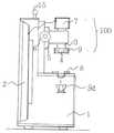
Translated fromKorean도1은 본 발명의 외형 사시도의 전면도1 is a front view of an external perspective view of the present invention;
도2는 본 발명의 외형 사시도의 후면도Figure 2 is a rear view of the outline perspective view of the present invention
도3은 본 발명의 단면 구성도Figure 3 is a cross-sectional configuration of the present invention
도4의 a는 현미 영상 광학계의 대물렌즈 구조의 설명도Fig. 4A is an explanatory diagram of the objective lens structure of the microscopic imaging optical system
도4의 b는 현미 영상 광학계의 증배렌즈 구조의 설명도4B is an explanatory diagram of a structure of a multiplication lens of a microscopic imaging optical system
도5는 대물렌즈의 조명장치 부문의 설명도5 is an explanatory diagram of a lighting device section of an objective lens;
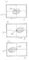
도6은 실물 측정 시 측정방법 설명도6 is an explanatory diagram of a measuring method when measuring in kind
도7은 회전스테이지에 이동 장치를 결합한 구조의 설명도7 is an explanatory diagram of a structure in which a moving device is coupled to a rotating stage;
도8은 현미 영상 광학계에 이동 장치를 결합한 설명도8 is an explanatory diagram in which a mobile device is coupled to a microscopic imaging optical system
도9는 본 발명을 교실에서 사용 시 설명도9 is an explanatory diagram when using the present invention in the classroom
도면의 부호에 대한 명칭의 간략한 설명Brief description of the designations for the symbols in the drawings
1. 영상박스 2. 평면영상장치 3. 렌즈케이스 4. 대물렌즈1.
4a. 증배렌즈 5. 상하이동대 6. 이동핸들 7. 영상변환장치4a.
8. 스테이지 9. 조명장치 10. 이동장치 11. 좌, 우 이동장치8.
11a. 좌, 우 이동핸들 12. 전, 후 이동장치 12a. 전, 후 이동 핸들11a. Left and
13. 이동장치 고정대 14. 회전스테이지13. Shifter Fixture 14. Rotating Stage
15. 손잡이 16. 측정기준선 100. 현미영상광학계15.
본 발명은 주로 학교에서 사용하는 현미경중 실물을 확대 할 수 있는 실체 현미경에 있어서 특히 교육용도에 유용하게끔 실물을 현미영상으로 확대하여 대형 평면 영상 장치로 여러 사람이 동시에 시청 할 수 있는 교육용 실체 현미 영상 장치에 관한 것이다In the present invention, the present invention is a stereo microscope capable of enlarging the real thing in the microscope used in school, especially for educational purposes. It is about a device
특히 빛 신호를 전기 신호로 변환하는 CCD와 같은 영상변환장치구조에 대물렌즈를 결합하여 현미 영상 광학계를 구성하고In particular, by combining an objective lens with an image conversion device such as a CCD that converts a light signal into an electric signal,
이와 같이 현미 영상 광학계에 의해 확대된 현미영상은 대형 평면 영상 장치에 현출하되The brown rice image enlarged by the brown rice optical system is displayed on a large planar imaging device.
현미영상광학계와 대형평면영상장치는 일체형으로 구성하여 휴대 및 이동을 간편하게 할 수 있는 것을 특징으로 하는 교육용 실체 현미영상장치에 관한 것이다.Microscopic imaging optical system and large planar imaging apparatus are related to the present invention, the actual microscopic imaging apparatus for education characterized in that the portable and mobile can be easily configured.
종래 실체 현미경은 학생 개개인이 사용하는 현미경으로서 교육 시 학생 수대로 현미경대수가 필요하다.Conventional stereoscopic microscopes are used by individual students, and the number of microscopes is required for each student.
예를 들면 30여 명되는 학생들을 교육시키기 위해서는 30여대의 현미경이 필요하고 이러한 현미경을 설치하기 위해서는 별도의 특수교실이 필요했으며 교사가 보는 현미경 영상과 학생들의 각각의 현미경 관측영상이 서로 달라 교육에 많은 불 편함이 있었다,For example, in order to educate about 30 students, 30 microscopes are needed, and a special classroom is required to install these microscopes. There was a lot of discomfort,
뿐만 아니라 곤충의 날개. 암석 및 광물의 결정체, 꽃잎의 암술, 수술 등의 크기 및 움직이는 모습을 그대로 학생들에게 현미영상으로 동시에 보여주면서 그 크기 등을 실측 할 수 있는 효과적인 현미영상기기가 없었다,As well as the wings of insects. The size and movement of rock and mineral crystals, petal pistils, surgery, etc. can be shown to students at the same time, and there is no effective micro-imaging device that can measure the size.
본 발명은 상기 문제점을 감안 하여In view of the above problems
· 실체 현미경 영상을 대형 화면에 현출하여 한 교실에 학생 전원이 동시에 관측 가능하고 교사가 의도하는 실물확대 영상을 전 학생에게 동시에 제시 할 수 있는 교육용 실체 현미경 구조를 제공하고자 한다.· Real-life microscope image will be displayed on a large screen to provide a real-life microscope structure for all students in the same room, and the teacher can present a real-life image to all students at the same time.
· 동시에 관측물의 실체 ,크기, 움직이는 형태, 등을 실제로 측정할 수 있는 구조를 제공하고자 하며At the same time, it is intended to provide a structure that can actually measure the reality, size, moving shape, etc. of observations.
· 현미경 구조의 형상을 가방 형상과 같이 이동하기 용이한 형상으로 전면에는 평면영상판(2)을 구비하고 후면 (또는 후면 일방)에는 현미 영상 광학계(100)를 구성하여 도 9와 같이 대형의 평면영상판(2)은 학생들의 시청 방향으로 구성하고 현미 영상 광학계(100)는 교사가 본기기의 후단에서 작동하면서 동시에 학생 들을 바라보면서 교육 할 수가 있는 구조를 제공하고자 한다.It is easy to move the shape of the microscope structure like a bag shape and has a
도 1및 도2와 도3과 같이 가방형과 같은 형상의 영상박스(1)전면에 평면영상판(2)을 구성하고 영상박스(1) 후단부에 현미 영상 광학계(100)를 구성한다.As shown in FIGS. 1 and 2 and 3, the
평면 영상판(2)은 PDP나 LCD 또는 프로젝션 시스템과 같은 영상기기로 구성 하며 한정 하지는 않지만 화면 크기는 12"부터 60"로 하되 휴대 이동하기에 적정한 20"-40" 로 한다.The
· 현미 영상 광학계(100)구조는 도4의 a 도4의 b와 같이 투사렌즈와 같은 특성을 갖는 대물렌즈(4)와 CCD(Charge Coupled Device) 또는 CMOS(Complementary Metal-Oxide Semiconductor)와 같이 광 신호를 전기 신호로 변환 하는 영상변환장치(7)를 결합하여 구성 한다.The microscopic imaging
영상변환장치(7)하단에는 렌즈케이스(3)를 구성하고 그 내부에 대물렌즈(4) 또는 대물렌즈(4)와 증배렌즈(4a)를 구성 한다,A
대물렌즈(4)는 초점거리 f가 1m/m에서 50m/m 사이로 짧은 초점거리를 갖는 투사렌즈구조로 하는 것이 적정하다.It is appropriate that the
대물렌즈(4)의 초점거리 f가 1m/m 이하이면 초점 거리가 너무 짧아 대물렌즈로서의 관측범위가 작아 그 기능이 어렵고 50m/m 이상이면 확대 배율이 매우 작기 때문이다This is because if the focal length f of the
도4의 a및 도4의 b와 같이 대물렌즈(4)와 스테이지(8)와의 거리 a와 대물렌즈(4)와 영상변환장치 (7)와의 거리 b의 비율이 즉 영상의 확대 배율이 된다.As shown in Figs. 4A and 4B, the ratio of the distance a between the
· a는 대물렌즈(4)와 스테이지(8)와의 거리이고A is the distance between the
b는 대물렌즈(4)와 영상변환장치(2)와의 거리이고 f는 대물렌즈의 초점 거리이다.b is the distance between the
상기 a와 b와 f와의 관계는
따라서 대물렌즈(4)의 초점거리(f)가 10m/m이고 b가 100m/m이면,

b:a는 100m/m:11.1m/m가 되므로 그 비율에 의한 배율은 약 9배가 되는 것이다.Since b: a becomes 100m / m: 11.1m / m, the magnification by the ratio is about 9 times.
같은 논리로 b가 100m/m이고 f가 5m/m이면 a는 5.26m/m가 된다.Similarly, if b is 100m / m and f is 5m / m, then a is 5.26m / m.
따라서 b:a=100:5.26≒약 19배가 된다.Thus b: a = 100: 5.26 times about 19 times.
같은 논리로 f가 1.5m/m이고 b를 100m/m로 고정시키면With the same logic, if f is 1.5m / m and b is fixed at 100m / m
a는 1,523이 되고 b:a는 100:1.523이 되므로 그 배율 은 약 65배가 된다.a becomes 1,523 and b: a becomes 100: 1.523, so the magnification is about 65 times.
이 경우 증배렌즈(4a)를 사용하여 그 배율을 증배 할 수 있다In this case, the magnification can be increased by using the
즉 이러한 현미 영상 광학계(100)는 도4의 b와 같이 배율을 좀 더 확대하기 위해서는 대물렌즈(4)상단에 증배렌즈(4a)를 추가 구성 한다.That is, the microscopic imaging
이와 같은 증배렌즈(4a)는 대물렌즈(4)에 의해 확대 된 영상을 확대하여 영상변환장치(7)에 결상하게 된다.The
도4의 b와 같이 a1은 증배렌즈(4a)와 대물렌즈(4)의 초점위치인 f와의 거리이고 b1은 증배렌즈(4a)와 영상변환장치(7)와의 거리이다.As shown in b of FIG. 4, a1 is the distance between the
증배렌즈(4a)의 배율구하는 논리도 상기 대물렌즈(4)와 같다.The logic for calculating the magnification of the
즉 도1의 b와 같이 a1은 a와 같고 b1은 b와 같다.That is, as in b of FIG. 1, a1 is equal to a and b1 is equal to b.
이러한 증배렌즈(4a)의 초점거리(f1)는 2m/m-20m/m사이가 적정하고 상기 대물렌즈(4)의 배율 구하는 공식과 동일하게 적용하여 배율 10-20배의 렌즈로 구성함 이 적정하다.The focal length f1 of the
· 따라서 본 발명의 실물 확대 배율은 b를 조정하거나 f를 1.5m/m에서 50m/m사이에서 선택하거나 증배렌즈(4a)를 추가하여 그 배율을 10배에서 100배 사이로 선택 사용 하는 것이 효율적이다.Therefore, the actual magnification of the present invention is effective to adjust b, select f between 1.5 m / m and 50 m / m, or select magnification between 10 and 100 times by adding
· 이와 같이 대물렌즈(4) 또는 증배렌즈(4a)에 의해 확대된 실물의 영상은 영상변환장치(7)에 결상되고 결상된 영상은 영상변환장치(7)와 결합된 공지된 전자회로에 의해 전자신호로 변환하여 평면영상판(2)에 표출하게 된다.The real image enlarged by the
대물렌즈(4)와 증배렌즈 (4a)사이에 즘(zoom)작용이 가능한 렌즈를 추가 구성 할 수도 있다A lens capable of zooming between the
이와 같은 대물렌즈(4)가 구성된 렌즈케이스(3)주변으로 도5와 같이 조명장치(9)를 추가 구성한다.The
이러한 조명장치(9)의 램프(9a)는 LED나 형광램프 구조로 구성한다. 이와 같은 조명장치(9)는 대물렌즈(4)하단의 관측물 표면을 조사(照射)하여 대물렌즈(4)로 영상을 입사하게 한다.The
또한 도5와 도7과 같이 관측물을 놓을 스테이지(8)는 360°회전 할 수 있는 회전스테이지(14)구조로 구성 할 수 있다In addition, as shown in Figures 5 and 7 the
도3과 같이 회전스테이지(14) 하단 영상박스(1) 내부에 램프(9a)를 추가 구성 하여 관측물 이면을 조사(照射)할 수 있다As shown in FIG. 3, a
도7은 이동장치(10)와 스테이지(8)를 결합한 것을 설명하기 위한 평면도이다7 is a plan view for explaining the combination of the moving
도8은 이동장치(10)와 현미영상광학계(100)를 결합 다음 상하이동대(5)에 결 합한 것을 설명하기 위한 평면도이다8 is a plan view for explaining that the
상기 도7과 도8의 구성은 이동장치의 실시의 예로서 전, 후 좌,우로 이동 할 수 있는 실시의 예로서 같은 논리로 다른 형상으로 구성할 수 있다7 and 8 may be configured in different shapes with the same logic as an example of an embodiment that may move left, right, front, and rear as an example of the implementation of the mobile device.
도7 및 도8과 같이 관측물을 전 후, 좌, 우로 이동 시킬 수 있는 이동장치(10)의 구조는 전, 후 이동장치(12)와 좌, 우 이동장치(11)를 각 각 구성하되 도면에는 표시되지 않았지만 좌 우 및 전 후 이동장치 (11.12) 내부에 정밀한 나사봉을 구성하고 동 나사봉은 각기 그 일방에 전, 후 이동핸들(12a)과 좌, 우 이동핸들(11a)과 각각 연계한다.As shown in FIGS. 7 and 8, the structure of the moving
전, 후 이동핸들(12a)에 연계된 나사봉을 회전시키면 전, 후 이동장치(12)가 전, 후로 이동 하면서 동시에 연계된 좌, 우 이동장치()와 좌, 우 이동핸들(11a)과 이에 연계된 도 7의 스테이지(8)나 또는 도8과 같이 현미영상 광학계(100) 전체를 전, 후 방향으로 이동 한다Rotating the screw rod associated with the front and rear movement handle 12a moves the front and
좌, 우 이동핸들(11a)에 연계된 나사봉을 회전 시키면 좌, 우 이동장치(11)와 연계된 도7의 스테이지(8)나 또는 도8의 현미영상 광학계(100) 전체를 좌. 우 방향으로 이동 하게 된다.Rotating the screw rods associated with the left and right moving
상기 좌, 우 이동장치(11)에는 스테이지(8)가 회전 할 수 있는 회전스테이지(14)를 결합하고 동 회전 스테이지(14)가 결합된 구조 전체를 다시 전, 후 이동장치(12)에 연결 한다.The left and right moving
상기와 같은 이동장치(10) 구조는 현미영상광학계 (100)자체 또는 상하 이동장치(5)와 이동장치고정대 (13)로 결합하여 사용 한다The structure of the moving
다음은 본 발명을 이용하여 실물을 확대하여 측정하는 방법에 관한 것이다The following relates to a method for enlarging and measuring a real object using the present invention.
도1및 도6과 같이 평면영상판(2)에 확대된 실물의 크기를 측정하기 위한 기준선(16)을 형성한다.As shown in FIGS. 1 and 6, a
이러한 기준선(16)은 평면영상판(2) 자체에 표시할 수도 있고 도 4의 b와 같이 대물렌즈(4)초점위치와 증배렌즈(4a)의 초점이 만나는 F점에 기준선이 표시된 투명판을 위치하여도 된다.The
이 경우 증배렌즈(4a)에 의해 대물렌즈(4)의 확대된 영상과 투명판의 기준선이 동시에 평면영상판(2)에 표시된다.In this case, the enlarged image of the
이러한 본 발명은 도 6의 a와 도6의 b, 도6의 c와 같이 예를 들어 나비의 눈을 측정하려면 회전스테이지(14)에 관측물인 나비를 놓고 도2의 상하이동대(5)를 이동핸들(6)에 의해 상하로 조정하여 초점을 맞춘 뒤 도 6의 a와 같이 관측 하고자 하는 눈 부분을 확대한 다음 이를 도6의 b와 같이 나비의 눈 부분을 기준선(16)의 일단에 맞춰놓고 좌, 우 이동핸들(11a)에 의해 현미영상광학계(100)를 도6의 c 방향으로 움직이면 그 움직인 만큼 마이크로 게이지 등의 계측기로 표시하게 하여 주므로 나비의 좌, 우 눈의 길이를 측정 할 수 있는 것이다.In the present invention, for example, as shown in FIG. 6A, 6B, and 6C, for example, to measure a butterfly's eye, a butterfly, which is an observation object, is moved to the
즉 상기와 같은 방법으로 전, 후 이동핸들(12a)을 움직여 주면 전, 후 길이가 측정되고 회전스테이지(14)를 회전시키면 필요한 방향의 길이를 측정 할 수 있는 것이다.That is, by moving the front and
도8과 같이 상기 이동장치(10) 구조를 현미영상광학계(100)와 결합 한 다음 상하이동대(5)와 연계 구성 한다As shown in FIG. 8, the structure of the
이러한 구성은 상하이동대(5)에 연계된 현미영상광학계(100)와 전 후, 좌 우 이동장치(11.12) 구조전체를 이동핸들(6)에 의해 상하로 조정하여 초점을 맞춘 뒤 도 6의 a와 같이 관측 하고자 하는 눈 부분을 확대한 다음 이를 도6의 b와 같이 나비의 눈 부분을 기준선(16)의 일단에 맞춰놓고 좌, 우 이동핸들(11a)에 의해 현미영상광학계(100)를 도6의 c 방향으로 움직이면 그 움직인 만큼 마이크로 게이지로 표시하게 하여 주므로 나비의 좌, 우 눈의 길이를 측정 할 수 있는 것이다Such a configuration is achieved by focusing the microscopic image
즉 스테이지(8)에 이동장치(10)를 결합 구성 하는 것과 현미영상광학계(100)에 이동장치(10)를 결합 구성 하는 차이는 스테이지(8)자체를 전 후, 좌 우로 움직이는 것과 현미영상광학계(100)자체를 움직이는 차이만 있을 뿐 작용효과는 같다In other words, the difference between combining the moving
본 발명은 현미영상광학계(100)를 영상박스(1) 상단에 구성하고 이를 필요에 따라 영상 박스(1) 내부에 인입하게 구성 할 수 있다.The present invention may be configured to configure the microscopic image
또한 영상박스(1)에서 현미영상광학계(100)를 필요에 따라 분리 하여 편리하게 관측 물을 관측 할 수 있다.In addition, it is possible to conveniently observe the observation by separating the microscopic
즉 필요에 따라 영상박스(1)후단의 현미영상광학계(100) 구조를 영상박스(1)자체에서 분리하여 떨어져 있는 관측물, 예컨대 화분에 있는 꽃의 암술, 수술 등 관측물에 대하여 확대 관측하고 필요에 따라 다시 현미영상광학계(100) 구조를 영상박스(1)에 결합 사용 할 수 있다That is, if necessary, the structure of the microscopic image
이때에는 현미영상광학계(100)와 영상박스(1)를 분리. 결합 할 수 있는 브라켓을 별도 로 추가 구성 할 수 있다At this time, the microscopic image
필요에 따라 도2와 같이 영상박스(1)후면에 교사가 학생들이 시청하는 평면 영상판(2)의 영상을 동시에 모니터 할 수 있는 모니터(17)를 구성 할 수 있다If necessary, as shown in FIG. 2, the back of the
이러한 본 발명은 도9와 같이 교사가 교탁위에 본 발명을 놓고 교육할 시 본 발명 1대로 교실의 학생, 예를 들면 30여 명되는 학생들을 교육시키기 위해서는 30여대의 현미경이 필요하고 이러한 현미경을 설치하기 위해서는 별도의 특수교실이 필요했으며 교사가 보는 현미경 영상과 학생들의 각각의 현미경 관측영상이 서로 달라 교육에 많은 불편함이 있던 것을 하나의 대형영상으로 동시에 교육 할 수 있는 것 이다In the present invention, when the teacher puts the present invention on the table as shown in Fig. 9, about 30 microscopes are required to educate students in the classroom, for example, about 30 students, according to the present invention. In order to do this, a separate special classroom was required, and the microscopic images seen by teachers and the microscope images of students were different from each other.
또한 본 발명의 구조는 현미영상광학계(100)와 평면영상판(2)을 도1과 같이 하나의 가방형태의 영상박스(1)구조에 일체형으로 구성함으로서 교사가 휴대, 이동하여 직접교실로 이동함으로서 별도의 특수교실이 불필요하고 교사가 의도하는 장소로 이동하여 전 학생에게 동시에 교육 할 수 있다.In addition, the structure of the present invention is that the microscopic imaging
스테이지(8) 또는 현미영상광학계(100)사이 필요 부분에 전, 후 좌,우 이동장치(11. 12)를 결합 하여 예컨대 곤충의 움직이는 범위, 암석의 결정체 등의 실물측정이 가능하므로 교육적 효과 또한 크다By combining the front and rear left and right movement devices (11.12) to the necessary part between the
뿐만 아니라 종래 일반현미경의 경우 20배 이상 확대된 영상을 학생 1인이 접안렌즈를 통해 1"-2"의 확대화면을 관측하는 반면에 본 발명은 상기 접안렌즈 시야 면적대비 40배-400배 이상인 20"- 40"의 대형의 평면영상판(2)으로 30-100명까지 확대된 현미영상을 동시에 관측 할 수 있으므로 그 교육적 효과가 매우 큰 것 이다In addition, in the case of the conventional general microscope, one student observes a magnified screen of 1 "-2" through an eyepiece while the image is enlarged 20 times or more, while the present invention provides a magnification of 40 to 400 times more than the eyepiece viewing area. The large 20 "-40" flat image plate (2) allows simultaneous observation of brown rice images of up to 30-100 people, which is a great educational effect.
Claims (6)
Translated fromKoreanPriority Applications (2)
| Application Number | Priority Date | Filing Date | Title |
|---|---|---|---|
| KR1020060100149AKR20080033027A (en) | 2006-10-12 | 2006-10-12 | Educational entity brown rice imaging device |
| US11/798,360US7969651B2 (en) | 2006-10-12 | 2007-05-14 | Educational stereo microscopic image display apparatus |
Applications Claiming Priority (1)
| Application Number | Priority Date | Filing Date | Title |
|---|---|---|---|
| KR1020060100149AKR20080033027A (en) | 2006-10-12 | 2006-10-12 | Educational entity brown rice imaging device |
Publications (1)
| Publication Number | Publication Date |
|---|---|
| KR20080033027Atrue KR20080033027A (en) | 2008-04-16 |
Family
ID=39302829
Family Applications (1)
| Application Number | Title | Priority Date | Filing Date |
|---|---|---|---|
| KR1020060100149ACeasedKR20080033027A (en) | 2006-10-12 | 2006-10-12 | Educational entity brown rice imaging device |
Country Status (2)
| Country | Link |
|---|---|
| US (1) | US7969651B2 (en) |
| KR (1) | KR20080033027A (en) |
Family Cites Families (13)
| Publication number | Priority date | Publication date | Assignee | Title |
|---|---|---|---|---|
| US2518240A (en)* | 1947-07-25 | 1950-08-08 | American Optical Corp | Projection microscope |
| USRE35409E (en)* | 1982-09-24 | 1996-12-24 | Moore; Sidney D. | Electrically addressable opto-electronic indicator for making dynamic evaluations of microscopic or larger subjects |
| US5086476A (en)* | 1985-11-04 | 1992-02-04 | Cell Analysis Systems, Inc. | Method and apparatus for determining a proliferation index of a cell sample |
| US5134662A (en)* | 1985-11-04 | 1992-07-28 | Cell Analysis Systems, Inc. | Dual color camera microscope and methodology for cell staining and analysis |
| GB8721878D0 (en)* | 1987-09-17 | 1987-10-21 | Buxton Micrarium Ltd | Microscope viewing arrangements |
| US4911543A (en)* | 1988-05-31 | 1990-03-27 | Hodgson R W | Microscope viewing apparatus for viewing a specimen image and an optical overlay pattern image in a comparison manner |
| US4932044A (en)* | 1988-11-04 | 1990-06-05 | Yale University | Tissue analyzer |
| JP3032214B2 (en)* | 1989-07-06 | 2000-04-10 | 株式会社トプコン | Surgical microscope |
| US5694242A (en)* | 1996-05-31 | 1997-12-02 | Lunax Company Limited | Multi-function microscope |
| US6396941B1 (en)* | 1996-08-23 | 2002-05-28 | Bacus Research Laboratories, Inc. | Method and apparatus for internet, intranet, and local viewing of virtual microscope slides |
| EP1022597A3 (en)* | 1999-01-19 | 2001-04-04 | Lunax Company Limited | Microscope |
| JP2000321505A (en)* | 1999-05-06 | 2000-11-24 | Sony Corp | Solid object observation scope |
| US6721094B1 (en)* | 2001-03-05 | 2004-04-13 | Sandia Corporation | Long working distance interference microscope |
- 2006
- 2006-10-12KRKR1020060100149Apatent/KR20080033027A/ennot_activeCeased
- 2007
- 2007-05-14USUS11/798,360patent/US7969651B2/ennot_activeExpired - Fee Related
Also Published As
| Publication number | Publication date |
|---|---|
| US7969651B2 (en) | 2011-06-28 |
| US20080088917A1 (en) | 2008-04-17 |
Similar Documents
| Publication | Publication Date | Title |
|---|---|---|
| Liu et al. | Real-time brightfield, darkfield, and phase contrast imaging in a light-emitting diode array microscope | |
| CN110431465B (en) | Microscope device for recording and displaying three-dimensional images of a sample | |
| US20130286347A1 (en) | Eye examination apparatus with digital image output | |
| CN109031642B (en) | Universal stereoscopic microscopic naked eye visualization display method and system device | |
| JP2016536093A5 (en) | ||
| CN106901680A (en) | The optical design of optical arena otoscope | |
| US20230221540A1 (en) | Continuous Zoom Stereoscopic Microscope with Adjustable Stereoscopic Angle | |
| CN111308690A (en) | Optical field electronic endoscopic device and imaging method thereof | |
| CN203458365U (en) | Stereo imaging device based on single-optical-path endoscope, light-splitting prism and double-path camera | |
| Arpa et al. | Single lens off-chip cellphone microscopy | |
| US20150036043A1 (en) | Bioscicon's cellphone camera - microscope universal adapter | |
| JP2011045553A5 (en) | ||
| CN104965302A (en) | Enhanced reality microscope | |
| CN103454761A (en) | Microscope device capable of observing object to be tested at multiple angles | |
| WO2018087665A1 (en) | Portable upright bright field microscope with smart device compatibility | |
| CN105158889B (en) | Stereoscopic microscopic imaging device and its method based on LED array illumination | |
| JP7664377B2 (en) | Microsurgery Support Devices | |
| KR20080033027A (en) | Educational entity brown rice imaging device | |
| CN110161778B (en) | Plant dissects and observes micro-distance case of shooing | |
| Muthanandam et al. | A review on stereomicroscope. | |
| CN202929284U (en) | High depth of field 3D digital microscope | |
| CN204575956U (en) | A kind of multifunctional bio microscope | |
| CN204720072U (en) | geometrical optics experiment auxiliary screen | |
| CN210039347U (en) | A Simple Observation Device That Can Demonstrate Small Hole Imaging of Outdoor Scenes | |
| CN209946611U (en) | Plant is dissected and is observed microspur case of shooing |
Legal Events
| Date | Code | Title | Description |
|---|---|---|---|
| PA0109 | Patent application | Patent event code:PA01091R01D Comment text:Patent Application Patent event date:20061012 | |
| AMND | Amendment | ||
| AMND | Amendment | ||
| PG1501 | Laying open of application | ||
| A201 | Request for examination | ||
| PA0201 | Request for examination | Patent event code:PA02012R01D Patent event date:20110316 Comment text:Request for Examination of Application Patent event code:PA02011R01I Patent event date:20061012 Comment text:Patent Application | |
| E902 | Notification of reason for refusal | ||
| PE0902 | Notice of grounds for rejection | Comment text:Notification of reason for refusal Patent event date:20120928 Patent event code:PE09021S01D | |
| AMND | Amendment | ||
| E601 | Decision to refuse application | ||
| PE0601 | Decision on rejection of patent | Patent event date:20130328 Comment text:Decision to Refuse Application Patent event code:PE06012S01D Patent event date:20120928 Comment text:Notification of reason for refusal Patent event code:PE06011S01I | |
| AMND | Amendment | ||
| J201 | Request for trial against refusal decision | ||
| PJ0201 | Trial against decision of rejection | Patent event date:20130416 Comment text:Request for Trial against Decision on Refusal Patent event code:PJ02012R01D Patent event date:20130328 Comment text:Decision to Refuse Application Patent event code:PJ02011S01I Appeal kind category:Appeal against decision to decline refusal Appeal identifier:2013101002790 Request date:20130416 | |
| J201 | Request for trial against refusal decision | ||
| PJ0201 | Trial against decision of rejection | Patent event date:20130417 Comment text:Request for Trial against Decision on Refusal Patent event code:PJ02012R01D Patent event date:20130328 Comment text:Decision to Refuse Application Patent event code:PJ02011S01I Appeal kind category:Appeal against decision to decline refusal Decision date:20131002 Appeal identifier:2013101002798 Request date:20130417 | |
| AMND | Amendment | ||
| PB0901 | Examination by re-examination before a trial | Comment text:Amendment to Specification, etc. Patent event date:20130429 Patent event code:PB09011R02I Comment text:Request for Trial against Decision on Refusal Patent event date:20130417 Patent event code:PB09011R01I Comment text:Amendment to Specification, etc. Patent event date:20130416 Patent event code:PB09011R02I Comment text:Request for Trial against Decision on Refusal Patent event date:20130416 Patent event code:PB09011R01I Comment text:Amendment to Specification, etc. Patent event date:20121024 Patent event code:PB09011R02I Comment text:Amendment to Specification, etc. Patent event date:20070207 Patent event code:PB09011R02I Comment text:Amendment to Specification, etc. Patent event date:20070117 Patent event code:PB09011R02I | |
| J501 | Disposition of invalidation of trial | ||
| PJ0501 | Disposition of invalidation of trial | Appeal kind category:Appeal against decision to decline refusal Request date:20130416 Appeal identifier:2013101002790 | |
| B601 | Maintenance of original decision after re-examination before a trial | ||
| PB0601 | Maintenance of original decision after re-examination before a trial | Comment text:Report of Result of Re-examination before a Trial Patent event code:PB06011S01D Patent event date:20130626 | |
| J301 | Trial decision | Free format text:TRIAL DECISION FOR APPEAL AGAINST DECISION TO DECLINE REFUSAL REQUESTED 20130417 Effective date:20131002 | |
| PJ1301 | Trial decision | Patent event code:PJ13011S01D Patent event date:20131002 Comment text:Trial Decision on Objection to Decision on Refusal Appeal kind category:Appeal against decision to decline refusal Request date:20130417 Decision date:20131002 Appeal identifier:2013101002798 |