KR20080031852A - Spinous process implant with deployable wings and implant implantation method - Google Patents
Spinous process implant with deployable wings and implant implantation methodDownload PDFInfo
- Publication number
- KR20080031852A KR20080031852AKR1020077024296AKR20077024296AKR20080031852AKR 20080031852 AKR20080031852 AKR 20080031852AKR 1020077024296 AKR1020077024296 AKR 1020077024296AKR 20077024296 AKR20077024296 AKR 20077024296AKR 20080031852 AKR20080031852 AKR 20080031852A
- Authority
- KR
- South Korea
- Prior art keywords
- wing
- implant
- guide
- small
- distraction
- Prior art date
- Legal status (The legal status is an assumption and is not a legal conclusion. Google has not performed a legal analysis and makes no representation as to the accuracy of the status listed.)
- Ceased
Links
Images


Classifications
- A—HUMAN NECESSITIES
- A61—MEDICAL OR VETERINARY SCIENCE; HYGIENE
- A61B—DIAGNOSIS; SURGERY; IDENTIFICATION
- A61B17/00—Surgical instruments, devices or methods
- A61B17/56—Surgical instruments or methods for treatment of bones or joints; Devices specially adapted therefor
- A61B17/58—Surgical instruments or methods for treatment of bones or joints; Devices specially adapted therefor for osteosynthesis, e.g. bone plates, screws or setting implements
- A61B17/68—Internal fixation devices, including fasteners and spinal fixators, even if a part thereof projects from the skin
- A61B17/70—Spinal positioners or stabilisers, e.g. stabilisers comprising fluid filler in an implant
- A61B17/7062—Devices acting on, attached to, or simulating the effect of, vertebral processes, vertebral facets or ribs ; Tools for such devices
- A61B17/7068—Devices comprising separate rigid parts, assembled in situ, to bear on each side of spinous processes; Tools therefor
- A—HUMAN NECESSITIES
- A61—MEDICAL OR VETERINARY SCIENCE; HYGIENE
- A61F—FILTERS IMPLANTABLE INTO BLOOD VESSELS; PROSTHESES; DEVICES PROVIDING PATENCY TO, OR PREVENTING COLLAPSING OF, TUBULAR STRUCTURES OF THE BODY, e.g. STENTS; ORTHOPAEDIC, NURSING OR CONTRACEPTIVE DEVICES; FOMENTATION; TREATMENT OR PROTECTION OF EYES OR EARS; BANDAGES, DRESSINGS OR ABSORBENT PADS; FIRST-AID KITS
- A61F2/00—Filters implantable into blood vessels; Prostheses, i.e. artificial substitutes or replacements for parts of the body; Appliances for connecting them with the body; Devices providing patency to, or preventing collapsing of, tubular structures of the body, e.g. stents
- A61F2/02—Prostheses implantable into the body
- A61F2/30—Joints
- A61F2/44—Joints for the spine, e.g. vertebrae, spinal discs
- A61F2/442—Intervertebral or spinal discs, e.g. resilient
- A61F2/4425—Intervertebral or spinal discs, e.g. resilient made of articulated components
- A—HUMAN NECESSITIES
- A61—MEDICAL OR VETERINARY SCIENCE; HYGIENE
- A61B—DIAGNOSIS; SURGERY; IDENTIFICATION
- A61B17/00—Surgical instruments, devices or methods
- A61B17/56—Surgical instruments or methods for treatment of bones or joints; Devices specially adapted therefor
- A61B17/58—Surgical instruments or methods for treatment of bones or joints; Devices specially adapted therefor for osteosynthesis, e.g. bone plates, screws or setting implements
- A61B17/68—Internal fixation devices, including fasteners and spinal fixators, even if a part thereof projects from the skin
- A61B17/70—Spinal positioners or stabilisers, e.g. stabilisers comprising fluid filler in an implant
- A61B17/7062—Devices acting on, attached to, or simulating the effect of, vertebral processes, vertebral facets or ribs ; Tools for such devices
- A61B17/7065—Devices with changeable shape, e.g. collapsible or having retractable arms to aid implantation; Tools therefor
- A—HUMAN NECESSITIES
- A61—MEDICAL OR VETERINARY SCIENCE; HYGIENE
- A61F—FILTERS IMPLANTABLE INTO BLOOD VESSELS; PROSTHESES; DEVICES PROVIDING PATENCY TO, OR PREVENTING COLLAPSING OF, TUBULAR STRUCTURES OF THE BODY, e.g. STENTS; ORTHOPAEDIC, NURSING OR CONTRACEPTIVE DEVICES; FOMENTATION; TREATMENT OR PROTECTION OF EYES OR EARS; BANDAGES, DRESSINGS OR ABSORBENT PADS; FIRST-AID KITS
- A61F2/00—Filters implantable into blood vessels; Prostheses, i.e. artificial substitutes or replacements for parts of the body; Appliances for connecting them with the body; Devices providing patency to, or preventing collapsing of, tubular structures of the body, e.g. stents
- A61F2/02—Prostheses implantable into the body
- A61F2/30—Joints
- A61F2/44—Joints for the spine, e.g. vertebrae, spinal discs
- A61F2/442—Intervertebral or spinal discs, e.g. resilient
- A61F2002/4435—Support means or repair of the natural disc wall, i.e. annulus, e.g. using plates, membranes or meshes
Landscapes
- Health & Medical Sciences (AREA)
- Orthopedic Medicine & Surgery (AREA)
- Neurology (AREA)
- Life Sciences & Earth Sciences (AREA)
- Surgery (AREA)
- Engineering & Computer Science (AREA)
- Biomedical Technology (AREA)
- General Health & Medical Sciences (AREA)
- Veterinary Medicine (AREA)
- Heart & Thoracic Surgery (AREA)
- Public Health (AREA)
- Animal Behavior & Ethology (AREA)
- Nuclear Medicine, Radiotherapy & Molecular Imaging (AREA)
- Medical Informatics (AREA)
- Molecular Biology (AREA)
- Vascular Medicine (AREA)
- Transplantation (AREA)
- Oral & Maxillofacial Surgery (AREA)
- Cardiology (AREA)
- Prostheses (AREA)
Abstract
Description
Translated fromKorean<우선권 주장><Claim priority>
미국 가특허 출원 제60/663,885호, 출원일: 2005년 3월 21일, 발명의 명칭: 전개 가능한 윙을 구비한 극돌간 돌기 임플란트 및 임플란트 이식 방법(Interspinous Process Implant having Deployable Wing and Method of Implantation), 발명자: 제임스 에프. 주커만(James F. Zucherman)외 다수(변리사 서류 번호 KLYC-01114US0)와;U.S. Provisional Patent Application No. 60 / 663,885, filed March 21, 2005, titled: Interspinous Process Implant having Deployable Wing and Method of Implantation, with deployable wings, Inventor: James F. James F. Zucherman et al. (Patent document No. KLYC-01114US0);
미국 가특허 출원 제60/663,918호, 출원일: 2005년 3월 21일, 발명의 명칭: 전개 가능한 윙을 구비한 극돌간 돌기 임플란트 및 임플란트 이식 방법(Interspinous Process Implant having Deployable Wing and Method of Implantation), 발명자: 제임스 에프. 주커만(James F. Zucherman)외 다수(변리사 서류 번호 KLYC-01114US1)와;U.S. Provisional Patent Application No. 60 / 663,918, filed March 21, 2005, titled: Interspinous Process Implant having Deployable Wing and Method of Implantation, Inventor: James F. James F. Zucherman et al. (Patent document No. KLYC-01114US1);
미국 가특허 출원 제60/664,076호, 출원일: 2005년 3월 22일, 발명의 명칭: 전개 가능한 윙을 척주 융합을 위한 부속물로서 구비한 극돌간 돌기 임플란트 및 임플란트 이식 방법(Interspinous Process Implant having Deployable Wing as an Adjunct to Spinal Fusion and Method of Implantation), 발명자: 제임스 에프. 주커만(James F. Zucherman)외 다수(변리사 서류 번호 KLYC-01114US2)와;U.S. Provisional Patent Application No. 60 / 664,076, filed March 22, 2005, titled: Interspinous Process Implant having Deployable Wing with deployable wing as an accessory for spinal fusion. as an Adjunct to Spinal Fusion and Method of Implantation). James F. Zucherman et al. (Patent document No. KLYC-01114US2);
미국 특허 출원 제11/ ,호, 출원일: 2006년 3월 17일, 발명의 명칭: 전개 가능한 윙을 구비한 극돌간 돌기 임플란트 및 임플란트 이식 방법(Interspinous Process Implant having Deployable Wing and Method of Implantation), 발명자: 제임스 에프. 주커만(James F. Zucherman)외 다수(변리사 서류 번호 KLYC-01114US3)와;US patent application Ser. No. 11 /, filed March 17, 2006, titled: Interspinous Process Implant having Deployable Wing and Method of Implantation with Inventor : James F. James F. Zucherman et al. (Patent document No. KLYC-01114US3);
미국 특허 출원 제11/ ,호, 출원일: 2006년 3월 17일, 발명의 명칭: 전개 가능한 윙을 구비한 극돌간 돌기 임플란트 및 임플란트 이식 방법(Interspinous Process Implant having Deployable Wing and Method of Implantation), 발명자: 제임스 에프. 주커만(James F. Zucherman)외 다수(변리사 서류 번호 KLYC-01114US4)와;US patent application Ser. No. 11 /, filed March 17, 2006, titled: Interspinous Process Implant having Deployable Wing and Method of Implantation with Inventor : James F. James F. Zucherman et al. (Patent document No. KLYC-01114US4);
미국 특허 출원 제11/ ,호, 출원일: 2006년 3월 17일, 발명의 명칭: 전개 가능한 윙을 척주 융합을 위한 부속물로서 구비한 극돌간 돌기 임플란트 및 임플란트 이식 방법(Interspinous Process Implant having Deployable Wing as an Adjunct to Spinal Fusion and Method of Implantation), 발명자: 제임스 에프. 주커만(James F. Zucherman)외 다수(변리사 서류 번호 KLYC-01114US5).US patent application Ser. No. 11 /, filed March 17, 2006, titled: Interspinous Process Implant having Deployable Wing as with deployable wing as an accessory for spinal fusion an Adjunct to Spinal Fusion and Method of Implantation, by James F. James F. Zucherman et al. Patent Attorney Docket No. KLYC-01114US5.
본 발명은 극돌간 돌기 임플란트(interspinous process implant)에 관한 것이다.The present invention relates to interspinous process implants.
척주(spinal column)는 인대, 근육, 척추골 및 추간판으로 주로 구성된 생체-기계적 구조체이다. 등뼈의 생체-기계적 기능으로는, (1) 몸무게 전달 및 머리와 몸통과 팔이 골반과 다리로 굽혀지는 움직임을 포함하는, 이른바 신체를 지지하는 기능과, (2) 이들 부분들 사이에서의 복잡한 생리적 움직임 기능과, (3) 척수(spinal cord)와 신경근의 보호 기능이 있다.The spinal column is a biomechanical structure consisting mainly of ligaments, muscles, vertebrae and intervertebral discs. Bio-mechanical functions of the spine include: (1) the function of supporting the body, including weight transfer and movement of the head, torso and arms to the pelvis and legs, and (2) the complexities between these parts. Physiological movement, and (3) spinal cord (spinal cord) and neuromuscular protection.
현대 사회가 고령화 되어감에 따라, 노인의 특징인 나쁜 척주 상태가 증가할 것으로 예상된다. 단지 일례로서 예를 들면, 고령화에 따라 척추 협착증(중앙관(central canal) 및 측방향 협착을 포함하되, 이에 국한되지는 않음)과 각면 관절병이 증가하고 있다. 척추 협착증은 추공 면적(즉, 신경과 혈관이 통과하는 공간을 마련하는 것)의 감소를 가져와서 경부 신경근을 압착하게 되어 신경근 통증을 유발한다. 참조 문헌: 험프리즈, 에스. 시.(Humpreys, S. C.) 등이 저술한 "C5-C6 추공 공간에 대한 구부림 및 수축 영향(Flexion and traction effect on C5-C6 foraminal space)", Arch. Phys. Med. Rehabil., 통권 제79호, 1105페이지 (1998년 9월 발간). 척추 협착증의 다른 증상으로는 척수병증이 있는데, 이는 목 통증 및 근육 약화를 유발한다. 전게서 참조. 목의 신장 및 동측성 회전(ipsilateral rotation)은 또한 추공 면적을 감소시키게 되며 통증, 신경근 압축, 및 신경계 손상을 가져온다. 참조 문헌: 전게서와, 그리고 유 제이. 유.(Yoo, J. U.) 등이 저술한 "인간 경부 척주의 신경유공 크기에 대한 경부 척주 운동의 영향(Effect of cervical spine motion on the neuroforaminal dimensions of human cervical spine), 척주(Spine), 통권 제17호, 1131페이지(1992년 11월 발간). 이와 반대로, 목의 굽힘은 추공 면적을 증가시킨다. 험프리즈 에스. 시.(Humpreys, S. C.) 등의 상기 논문 1105페이지 참조.As modern society ages, it is expected that the condition of the bad spine, which is characteristic of the elderly, will increase. As just one example, with age, spinal stenosis (including but not limited to central canal and lateral stenosis) and facet joint disease are increasing. Spinal stenosis results in a reduction in the area of vertebrae (ie, providing space for the nerves and blood vessels to pass), resulting in compression of the cervical nerve roots, causing nerve root pain. References: Humphreys, S. "Flexion and traction effect on C5-C6 foraminal space" by Humpreys, S. C. et al., Arch. Phys. Med. Rehabil., Vol.79, no.1105 (published September 1998). Another symptom of spinal stenosis is myelopathy, which causes neck pain and muscle weakness. See previous chapter. Neck elongation and ipsilateral rotation also decreases the pore area and results in pain, nerve root compression, and nervous system damage. REFERENCES: Written text, and Yu J .. "Effect of cervical spine motion on the neuroforaminal dimensions of human cervical spine, Spine", ed. 17, by Yoo, JU, et al. , Page 1131 (November 1992) Conversely, bending of the neck increases the pore area, see page 1105 of Humphreys, SC et al.
시간이 지남에 따라, 척주 영역뿐만 아니라 흉관 및 허리 영역의 디스크 높이의 감소로 인해 퇴행성 증폭반응(degenerative cascade)이 야기되고, 이와 함께 운동 세그먼트의 모든 구성품들의 퇴화되어 세그먼트의 불안정성이 야기되며 극단적으로 척추 협착증이 야기된다. 열화 과정 중에 디스크는 탈장되거나 그리고/또는 내부가 헐게 되어 만성적으로 아프게 된다. 이러한 증상은 전방 (디스크) 및 후방 (각면 및 소공(foramen)) 구조체 모두로부터 유발되는 것으로 보이는 경우, 환자들은 펴거나 굽히는 위치를 견딜 수 없다.Over time, declining the height of the discs in the thoracic and lumbar regions, as well as in the spinal region, leads to degenerative cascades, with the degeneration of all components of the motor segment resulting in instability of the segments and extremely Spinal stenosis is caused. During the deterioration process, the disc is herniad and / or internally torn and becomes chronically ill. If this symptom appears to originate from both the anterior (disc) and posterior (angular and foramen) structures, patients are unable to withstand the position of flexing or flexing.
협착증과 관련된 통증은 약물치료 및/또는 외과수술에 의해 경감될 수 있다.모든 사람들, 특히 고령자를 위한 중한(생명의 위험을 수반하는) 외과 수술의 필요성을 없애는 것이 바람직하다.Pain associated with stenosis can be alleviated by medication and / or surgery. It is desirable to obviate the need for moderate (with risk of life) surgery for all people, especially older people.
따라서, 척추 협착증에 의해 야기되는 통증을 완화시키고 척추에 대한 손상이나 척추의 퇴행에 의해 야기되는 여타의 통증과 같은 상태를 완화시키는 척주 임플란트의 개발에 대한 요구가 있다. 이렇게 요구되는 임플란트는 추공 면적을 증가시키며 척주의 신경 및 혈관에 작용하는 압력을 감소시키기 위해 척추골들 사이의 공간을 신연(distract) 또는 증가시킨다.Accordingly, there is a need for the development of spinal implants that alleviate pain caused by spinal stenosis and alleviate conditions such as damage to the spine or other pain caused by spinal degeneration. Implants thus required distract or increase the space between the vertebrae in order to increase the pore area and reduce the pressure on the nerves and blood vessels of the spinal column.
척주의 생리학적인 것이 유지될 수 있도록 하는 척주 임플란트용의 최소 침투 방식 외과적 임플란트 의술의 개발에 대한 요구도 있다.There is also a need for the development of minimally invasive surgical implant surgery for spinal implants to ensure that the physiology of the spinal column is maintained.
더욱이, 척주의 특별한 해부학적 구조를 수용하며 척주에 대한 추가적인 외 상을 최소화하며 침투 방식의 외과적 임플란트 방법의 필요성을 일소하는 임플란트에 대한 요구도 있다. 또한, 척주의 펴기에 의해 악화되는 척주의 역 상태도 취할 수 있도록 하는 것에 대한 요구도 있다.Moreover, there is a need for implants that accommodate the special anatomical structure of the spinal column, minimize additional trauma to the spinal column and obviate the need for invasive surgical implant methods. There is also a need to be able to take the inverse state of the spinal column which is exacerbated by the spinal column unfolding.
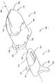
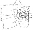
도 1a는 본 명세서에 참고로 포함되는 2004년 5월 20일 출원된 미국 특허 출원 제10/850,267호에 설명된 임플란트의 사시도이다. 임플란트(100)는 제1 윙(130), 스페이서(120), 및 조직내 도입 확장기(lead-in tissue expander)(이하에서는 신연 안내부(distraction guide)라고도 함)(110)를 포함한다. 특별한 본 실시예에서의 신연 안내부는 쐐기형이다. 즉, 임플란트는 임플란트(150)의 근위 단부에서부터 신연 안내부(110)가 스페이서(120)와 연결되는 영역(150)까지 확장되는 단면을 갖는다(도면을 위한 기준은 극돌기들 사이의 임플란트 삽입 지점에 기초하였다). 이와 같이, 신연 안내부(110)는 임플란트(100)가 극돌기들 사이에 외과적으로 삽입될 때에 연한 조직과 극돌기들의 신연을 개시시키는 기능을 한다. 신연 안내부(110)는 임플란트(100)가 경부 척추골의 극돌기들 사이로 용이하게 삽입될 수 있게 하기 위하 뾰족하게 하는 등의 방식으로 형성될 수 있다는 것을 이해할 수 있다. 삽입 기술은 뼈 및 둘러싸는 조직 또는 인대에 대한 방해를 가능한 한 적게 하여서, 그 부분들에 대한 외상을 줄이고 조기 회복을 촉진하고 정상인 해부학적인 것의 동요를 방지할 수 있도록 하는 것이 바람직하다. 도 1a 및 도 1b의 실시예에 있어서는, 어떠한 극돌기 뼈도 제거하는 것을 요하지 않으며 극돌기에 바로 결합되어 있는 인대 및 조직을 신체로부터 절단하거나 제거하는 것을 요하지 않는다. 일례로, 상부 경부 척추골의 극돌기를 부분적으로 완충시키는 하부 척추골의 가시끝인대(supraspinal ligament) 혹은 목덜미인대(ligamentum nuchae)(가시끝인대에 해당됨)를 절단할 필요가 없다.1A is a perspective view of the implant described in US Patent Application No. 10 / 850,267 filed May 20, 2004, which is incorporated herein by reference. The
알 수 있는 바와 같이, 스페이서(120)는 임플란트(100)의 종축(125)에 대해 수직한 눈물 모양의 단면으로 구성할 수 있다. 이와 같은 방식에 있어서, 스페이서(120)의 형상은 쐐기형 공간에, 혹은 임플란트(100)가 안에 위치되는 인접하는 극돌기들 사이의 공간의 일부에 대략 들어맞는다. 도 1a에 도시된 바와 같이, 스페이서(120)(그리고 제1 윙(108))는 C6 및 C7 척추골의 극돌기들(즉, C6-C7 운동 세그먼트) 사이에서의 위치를 위해 바람직하게도 C6 및 C7의 극돌기들(그리고/또는 판(laminae))의 해부학적 형상 또는 윤곽을 수용하도록 한 형상으로 형성된다. 이와 같은 형상과 동일한 형상 또는 그 변형 형상은 일례로 흉관 또는 허리 부위의 다른 운동 세그먼트들을 수용하는 데에도 사용될 수 있다. 또 다른 실시예에서, 스페이서(120)는 원형, 쐐기형, 달걀모양(oval), 난형(ovoid), 풋볼형, 모서리를 둥글게 한 직사각형, 그리고 기타 다른 형상 등의 여러 대안적인 형상으로 구성할 수 있다. 스페이서(120)의 형상은 의사가 임플란트를 극돌기의 표면의 전방 부분에 가능한 한 긴밀하게 위치시킬 수 있도록 특정 환자에 맞추어 선택될 수 있다. 스페이서(120)용으로 선택된 형상은 신연을 받게 되는 극돌기들과 임플란트(100)의 접촉 표면적에 영향을 미칠 수 있다. 임플란트(100)와 극돌기들 사이의 접촉 면적이 증가하게 되면 가시 프레임(spinous frame)과 임플란트(100) 사이의 하중력이 분산될 수 있다.As can be seen, the
제1 윙(130)도 마찬가지로 스페이서(120)와 신연 안내부(110)의 종축(125)에 수직한 눈물 모양 단면으로 형성된다. 제1 윙(130)의 크기는 특히 척추의 축을 따라서는 스페이서(120)의 크기보다 클 수 있고, 종축(125)을 따른 삽입 방향으로의 임플란트(100)의 측방향 변위를 제한하거나 차단할 수 있다. 이와 같은 스페이서(120)에 의하면, 제1 윙(130)은 타원형, 쐐기형, 원형, 달걀모양(oval), 난형(ovoid), 풋볼형, 모서리를 둥글게 한 직사각형, 그리고 기타 다른 형상 등의 또 다른 형태의 횡단면 형상을 가질 수 있다.Similarly, the
도 1a의 임플란트(100)는 신연 안내부(110)와 별개인 조절 가능한 윙(160)(여기에서는, 제2 윙이라고도 한다), 스페이서(120), 및 제1 윙(130)을 추가로 포함한다. 제2 윙(160)은 임플란트(100)가 일단 인접하는 극돌기들 사이에 위치되면 신연 안내부(110)(그리고/또는 스페이서(120))와 접촉 가능해진다. 제2 윙(160)은 제1 윙(130)과 유사하게 임플란트(100)의 측방향 변위를 제한하거나 차단할 수 있는데, 그렇지만 그 변위를 삽입 반대 방향으로는 제한하거나 차단할 수 없다. 제1 윙(130)과 제2 윙(160) 모두가 임플란트(100)와 연결될 때에 임플란트(100)는 인접하는 극돌기들 사이에 위치되고, 그 극돌기들의 일부는 제1 윙(130)과 제2 윙(160) 사이에 개재되어서 종축(125)을 따른 변위를 제한한다. 알 수 있는 바와 같이, 제2 윙(160)은 횡단면이 눈물 모양으로 형성된다. 제2 윙(160)을 통과하는 공간(170)을 한정하는 립(180)은 제2 윙(160)이 신연 안내부(110)를 지나서 신연 안내부(110) 및/또는 스페이서(120)와 만나서 연결되게 한다. 제2 윙(160)은 스페이서(120) 상에, 혹은 스페이서(120)에 인접한 신연 안내부(110)의 일부분에 간섭-끼워맞춤(interference-fit)되게 구성될 수 있다. 제2 윙(160)이 간섭-끼워맞춤되는 경우, 제2 윙(160)을 임플란트(100)의 나머지 부분에 대해서 체결시킬 추가의 부착 장치가 필요 없다.The
선택적으로, 제2 윙(160)을 임플란트(100)의 나머지 부분에 대해서 고정시키는 데에는 여러 가지 체결구(fastener)들이 사용될 수 있다. 일례로, 도 1a는 제2 윙(160)의 후방 단부에 설부(158)를 구비하는 눈물 모양의 제2 윙(160)을 포함하는 임플란트(100)의 실시예를 도시하고 있다. 구멍(155)은 상기 설부(158)를 관통하여 배치되고, 제2 윙(160)이 임플란트(100)의 나머지에 대해서 외과적으로 삽입시킴으로써 제위치에 오게 되었을 때에 스페이서(120) 상의 대응하는 구멍(156)과 정렬된다. 나사 스크류(154)는 제2 윙(160)을 스페이서(120)에 고정시키기 위해 전방-후방 방향으로 정렬된 구멍(155, 156)을 통하여 삽입될 수 있다. 전방에서 후방으로의 삽입 방향은 스크류(154)로 하여금 구멍(155, 156)과 임플란트(100)의 나머지 부분을 종축(125)에 대해 대체로 수직한 방향으로 따라서 결합시키게 한다. 이와 같은 동작은 제2 윙(160)을 임플란트(100)의 나머지 부분에 고정시키기 위하여 의사가 나사(154)를 사용하는 것을 필요로 할 때에 가장 편리한 것이다. 제2 윙(160)은 또한 어떤 또 다른 기구, 일례로 신연 안내부(110)와 스페이서(120) 중 어느 하나의 만입부(indentation)와 결합하는 돌출부를 갖는 가요성 힌지(flexible hinge)(도면에 도시되지 않음)에 의해 스페이서(120)에 추가로 고정될 수 있다. 선택적으로, 제2 윙(160)은 어떤 또 다른 기구에 의해서 신연 안내부(110)와 스페이서(120) 중 어느 하나에 고정될 수 있다.Optionally, various fasteners may be used to secure the
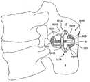
도 1b는 본 명세서에 참고로 포함되는 주커만(Zucherman) 등의 미국 특허 제6,695,842호에 설명된 임플란트의 사시도이다. 임플란트(200)는 스페이서(200), 제1 윙(230), 및 조직내 도입 확장기(lead-in tissue expander)(이하에서는 신연 안내부(distraction guide)라고도 함)(210)를 포함한다. 임플란트(200)의 본체는 인접하는 극돌기들 사이에 삽입되어 뼈 또는 인대로의 부착이 없이도 제위치(필요한 경우)에 유지된다.FIG. 1B is a perspective view of the implant described in US Pat. No. 6,695,842 to Zucherman et al., Incorporated herein by reference. The
신연 안내부(210)는 팁을 포함하고, 이 팁으로부터는 상기 신연 안내부(210)가 팽창하며, 상기 팁은, 팁이 극돌간 인대의 개구를 뚫을 수 있도록 그리고/또는 초기의 작은 팽창된 개구 안으로 삽입될 수 있도록, 충분히 작은 직경을 갖는다. 신연 안내부(210)의 직경 및/또는 단면적은 스페이서(220)의 직경과 실질적으로 비슷해질 때까지 점진적으로 증가한다. 테이퍼진 전방 단부는 의사가 임플란트(200)를 인접하는 극돌기들 사이로 가압시키는 것을 용이하게 한다. 인접하는 극돌기들 사이로 임플란트(200) 본체를 가압시킬 때에, 신연 안내부(210)의 전방 단부는, 인접하는 극돌기들 사이의 공간이 스페이서(220)의 직경과 거의 같아지도록, 인접하는 극돌기들을 신연시키고 극돌간 인대를 넓힌다.The
도 1b에 도시된 바와 같이, 스페이서(220)는 그 단면이 타원형으로 형성되고, 스페이서(220)가 극돌기들의 불균일한 표면에 대해 자체 정렬될 수 있도록 선회될 수 있다. 자체 정렬은 압축 하중이 뼈의 표면을 가로질러서 분포될 수 있게 한다. 주커만의 미국 특허 제6,695,842호에서 의도했던 바와 같이, 스페이서(220)의 직경은, 일례로 6밀리미터, 8밀리미터, 10밀리미터, 12밀리미터, 14밀리미터로 할 수 있다. 이와 같은 직경들은 스페이서(220)가 극돌기들을 신연시켜서 유지하는 높이라고 칭한다. 타원형 형상의 스페이서(220)에 있어서, 상기 선택된 높이(즉, 직경)는 타원을 가로지르는 단축 치수(혹은 단경 치수)(minor dimension)의 크기이다. 장축 치수(혹은 장경 치수)는 하나가 다른 것의 위에 있는 극돌기의 정렬에 대해 가로지르는 것이다.As shown in FIG. 1B, the
제1 윙(230)은 하부 부분(231)과 상부 부분(232)을 갖는다. 상부 부분(232)은 바람직하기로는 L4 척추골(L4-L5 배치를 위한 것) 또는 L5 척추골(L5-S1 배치를 위한 것)의 극돌기(및/또는 판)의 해부학적 형상 또는 윤곽을 수용하도록 하는 형상으로 형성된다. 이와 같은 형상과 동일한 형상 또는 그 변형 형상은 경부 및 흉관 영역의 운동 세그먼트와 같은 기타 다른 운동 세그먼트들을 수용하도록 하는 데 사용될 수 있다. 하부 부분(231)은 둥글게 하여서 극돌기들을 수용하도록 할 수 있다. 제1 윙(230)의 하부 부분(231)과 상부 부분(232)은 임플란트(200)가 인접하는 극돌기들 사이에 삽입될 때에 정지 기구(stop mechanism)로서 작용한다. 임플란트(200)는 제1 윙(230)의 표면을 지나서는 삽입될 수 없다. 또한, 임플란트(200)가 일단 삽입되면 제1 윙(230)은 임플란트(200)의 임의의 측면에서 측면으로의 이동이나 전방에서 후방으로의 이동을 방지할 수 있다.The
도 1a의 임플란트(100)에서와 마찬가지로, 도 1b의 임플란트(200)도 제2 윙(260)을 추가로 포함한다. 제2 윙(260)은 제1 윙(230)과 마찬가지로 하부 부분(261)과 상부 부분(262)을 포함하고, 상기 하부 및 상부 부분의 크기 및/또는 형상은 극돌기 및/또는 판(lamina)의 해부학적 형상이나 윤곽을 수용하도록 되어 있다. 제2 윙(260)은 체결구(254)에 의해 임플란트(200)의 본체에 고정될 수 있다. 제2 윙(260)은 또한 정렬 탭(268)을 구비한다. 제2 윙(260)이 임플란트(200)의 본체 상에 초기에 배치되었을 때, 정렬 탭(268)은 정렬 트랙(203)과 결합된다. 정렬 탭(268)은 정렬 트랙(203) 내에서 활주하고, 상기 조정가능한 제2 윙(260)을 제1 윙(230)에 실질적으로 평행하게 유지시키는 데 일조를 한다. 임플란트(200)의 본체가 환자 안으로 삽입되고 제2 윙(260)이 부착되면, 삽입 방향이나 삽입 방향에 반대되는 방향으로의 종축(225)을 따르는 변위가 제한되거나 차단될 수 있다. 또한, 제2 윙(260)은 측면에서 측면으로의 이동이나 전방에서 후방으로의 이동을 방지할 수 있다.As with the
도 1a의 임플란트(100)와 도 1b의 임플란트(200)에 있어서, 임플란트(100, 200)가 극돌기들 사이에 위치된 후에 제2 윙(160, 260)이 임플란트(100, 200)와 연결되는 경우, 임플란트(100, 200)를 위치시키고 후속해서 제2 윙(160, 260)을 임플란트(100, 200)와 연결시키는 과정은 쌍무적인 해결책을 요하게 되는바, 의사는 극돌간 인대의 양 측면으로 접근해야 하는데, 그 한 측면은 삽입 방향의 운동이 제1 윙(130, 230)에 의해 만족스럽게 제한될 수 있도록 극돌간 인대를 뚫고 그리고/또는 신연시켜서 임플란트(100, 200)를 위치시키는 것이고, 다른 측면은 삽입 반대 방향으로의 운동이 제2 윙(160, 260)에 의해 만족스럽게 제한될 수 있도록 제2 윙(160, 260)을 부착시키는 것이다.In the
전개 가능한 제2 윙을 구비한 임플란트Implant with deployable second wing
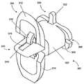
도 2a 내지 도 3b를 참조하면, 본 발명에 따른 임플란트(300) 및 그 임플란트를 위치시키는 방법은 일 실시예에서는, 종축(25)을 따르는 운동을 제한 또는 차단을 하기 위해 극돌기의 제1 측면으로 접근을 해서 위해서 요구되는 의사의 요구에 의해서만 전개될 수 있도록 주 본체(301)와 결합된 전개 가능한 제2 윙(360)을 포함한다.Referring to FIGS. 2A-3B, the
도 2a에 도시된 바와 같이, 임플란트(300)는 고정된 스페이서(320)와 신연 안내부(310)를 구비하는 주 본체(301)를 포함한다. 신연 안내부(310)는 제1 작은 날개(winglet)(상부 작은 날개라고도 함)(312)와 제2 작은 날개(하부 작은 날개라고도 함)(314)를 포함하고, 제1 구성으로 배열되었을 때에는 팁을 포함할 수 있고, 상기 팁으로부터는 신연 안내부(310)가 확장되고, 상기 팁은 그 팁이 극돌간 인대 내에 있으며 극돌기들 사이에 있는 개구를 뚫고 그리고/또는 작은 초기의 넓혀진 개구 안으로 삽입될 수 있다. 신연 안내부(310)의 직경 및/또는 단면적은 스페이서(320)의 직경과 실질적으로 비슷해질 때까지 점진적으로 증가한다. 이와 관련하여, 도 2a의 신연 안내부(310)는 제1 구성으로 배열되었을 때에는 상기한 바와 같이 신연 안내부와 유사할 수 있다. 작은 날개(312, 314)는 힌지 연결될 수 있거나 아니면 주 본체(301)와 선회 가능하게 연결되고, 이에 따라 작은 날개(312, 314)는 일단 임플란트(300)가 극돌기들 사이에 위치되면 제2 구성(도 2b)으로 배열될 수 있게 된다. 제2 구성에 있어서, 작은 날개(312, 314) 중 하나 또는 둘다는 삽입 방향과 반대되는 방향으로 가압될 때에는 극돌기 및/또는 관련된 조직 중 적어도 하나와 맞닿게 되고, 이에 의해 종축(25)을 따르는 운동을 제한하게 된다. 따라서 제2 구성으로 배열될 때에 신연 안내부(310)는 도 2b에 도시된 바와 같이 제2 윙(360)이 된다.As shown in FIG. 2A, the
임플란트(300)는 삽입 본체(372) 및 제 1 윙(330)을 구비하는 삽입체(370)를 포함한다. 도 2b에 도시된 바와 같이, 삽입체(370)는 주 본체(301)와 정합되어서 임플란트(300)의 신연 안내부(310)를 제2 구성으로 배열하고, 이에 의해 제2 윙(360)이 전개되게 된다. 주 본체(301)와 삽입체(370)의 정합을 용이하게 하기 위해, 스페이서(320)는 삽입 본체(372)를 수용하도록 하는 크기와 형상으로 되어 있고 주 본체(301)의 원위 단부로부터 접근 가능한 공동을 포함한다. 상부 작은 날개(312) 및 하부 작은 날개(314)는 적어도 부분적으로는 상기 공동 안으로 연장되고, 이에 따라 삽입 본체(372)가 상기 공동 안에 수용되면 삽입 본체(372)는 부분들을 변위시키고, 이에 의해 신연 안내부(310)는 제2 구성으로 배열되게 된다. 도시된 실시예에서, 상부 작은 날개(312) 및 하부 작은 날개(314) 각각은 신연 안내부(310)가 제1 구성에 있을 때에 공동 안으로 돌출하는 곡형 돌출부를 포함하는 레버(316, 318)를 포함한다. 삽입체(370)의 삽입 본체(372)가 공동을 채울 때에, 삽입 본체(372)는 제1 레버(316) 및 제2 레버(318)와 접촉하여서, 상기 제1 레버(316)와 제2 레버(318)에 힘을 가하여서 힌지 연결된 상부 작은 날개(312)와 힌지 연결된 하부 작은 날개(314)의 선회 운동으로 옮겨진다. 삽입 본체(372)는 제1 레버(316) 및 제2 레버(318) 각각에 대응하는 제1 홈(376) 및 제2 홈(378)을 구비하는 테이퍼진 근위 단부(374)를 선택적으로 구비할 수 있다. 근위 단부(374)의 테이퍼진 형상은 상부 작은 날개(312) 및 하부 작은 날개(314)가 점진적으로 전개되게 하고, 삽입 본체(372)가 공동 내에 완전히 안착되었을 때에는 완전히 전개되게 한다. 주 본체(301)는 일례로 삽입 공구(미도시)를 수용하도록 노치(305)가 형성되어 있는 플랜지(303)를 포함하는 것으로 도시되었다. 삽입 본체(372)가 공동 안에 안착되면, 제1 윙(330)의 상부 탭(332) 및 하부 탭(331)은 플랜지(303)의 절결부(322) 안에 안착된다.The
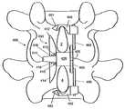
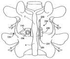
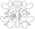
도 3a를 참조하면, 임플란트(300)의 주 본체(301)는 표적으로 삼은 운동 세그먼트의 인접하는 극돌기들 사이에 위치된 것으로 도시되어 있다. 운동 세그먼트는 허리 영역 내에 있는 것으로 도시되었지만, 특히 고정 스페이서(320)가 사용되는 또 다른 실시예에서 본 발명에 따른 임플란트(300)는 흉관 및 경부 영역의 운동 세그먼트에 위치될 수 있다. 주 본체(301)는Referring to FIG. 3A, the
상부 및 하부 인접하는 극돌기(2, 4)들 사이의 극돌간 인대를 초기에 개구를 통해서 극돌간 인대의 우측으로, 대략적으로는 후방으로부터 해서, 상부 극돌기(2)들이 연장하기 시작하는 척추골의 우측 하위 관절 각면(6)으로 접근시킴으로써 위치되는 것으로 도시되어 있다. 주 본체(301)는 한 이상의 삽입 공구(미도시)와 결합될 수 있고, 신연 안내부(310)는 제1 구성으로 배열될 수 있다. 신연 안내부(310)의 팁은 극돌간 인대를 따르는 지점에 대략 인접하게 위치되고, 이어서 신연 안내부(310)는 극돌간 인대를 통해서 가압되어, 극돌간 인대를 뚫고 그리고/또는 극돌간 인대의 섬유를 분리 및 신연시킨다. 주 본체(301)는 이어서 스페이서(320)가 인접하는 극돌기(2, 4)들 사이에 위치될 때까지 극돌간 인대를 통해서 가압되고, 이에 따라 스페이서(320)는 극돌기(2, 4)들에 의해 가해진 하중을 지지한다.The right intervertebral ligament between the upper and lower adjoining spinous processes 2, 4, initially through the opening to the right of the intervertebral ligament, approximately from the rear, to the right of the vertebrae where the upper spinous processes 2 begin to extend. It is shown as being positioned by approaching the lower
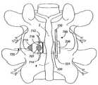
도 3b를 참조하면, 일단 임플란트(300)가 소망하는 대로 위치되면, 삽입 공구는 개구로부터 제거될 수 있고, 삽입체(370)는 주 본체(301)의 원위 단부에 위치될 수 있다. 삽입 본체(372)는 삽입체(370)의 근위 단부(374)가 제1 레버(316) 및 제2 레버(318)와 접촉할 때까지 주 본체(301) 내에서 공동 안으로 가압된다. 삽입체(370)는 이어서 종축(325) 방향으로 더 가압되고, 이에 따라 삽입체(370)는 제1 레버(316)와 제2 레버(318)를 삽입체(370)로부터 멀리 가압하고, 이에 의해 상부 작은 날개(312) 및 하부 작은 날개(314)는 각각 제1 힌지(313)와 제2 힌지(315)를 중심으로 해서 선회하게 된다. 제1 레버(316)와 제2 레버(318)가 공동으로부터 변위되면, 제1 레버(316)와 제2 레버(318)는 테이퍼진 근위 단부(374)의 대응하는 홈(376, 378)을 따라서 안내된다. 삽입체(370)가 주 본체(301)의 공동 안에 안착되면, 상부 작은 날개(312) 및 하부 작은 날개(314)는 제2 윙(360)으로서 전개된다. 일단 삽입 본체(372)가 주 본체(301) 안에 안착되면 삽입 공구는 절개부로부터 제거될 수 있다. 알 수 있는 바와 같이, 상부 극돌기의 일부와 하부 극돌기의 일부는 제1 윙(330)과 제2 윙(360) 사이에 개재되어서, 종축(325)을 따르는 운동을 제한한다.Referring to FIG. 3B, once the
본 발명에 따른 임플란트 및 극돌기들 사이에 그 임플란트를 위치시키는 방법은 이상에서 설명한 실시예에 제한되는 것을 의미하는 것이 아니며, 달리 말이 없는 한은, 삽입체를 인접하는 극돌기들 사이에 위치된 주 본체 내에 가압시킴으로써 전개될 수 있는 제2 윙을 구비하는 임의의 임플란트를 포함하는 것을 의미하는 것이다. 당해 분야의 숙련된 자들이라면 수많은 각기 다른 변형들이 있을 수 있음을 쉽고도 명백하게 알 수 있다. 일례로, 선택적인 실시예에서, 도 2a 내지 도 3b의 임플란트(300)의 주 본체(301)는 주 본체(301)와 선회가능하게 결합된 하부 작은 날개(314)를 포함하고, 이 때 상부 작은 날개(312)는 주 본체(301)에 고정되게 결합된다. 삽입체(370)는 주 본체(301)의 공동 내에 안착되었을 때에 하부 작은 날개(314)만을 전개시키도록 구성될 수 있다.The method of positioning the implant between the implant and spinous processes according to the present invention does not mean to be limited to the embodiments described above, and unless otherwise stated, the insert is placed within a main body located between adjacent spinous processes. It is meant to include any implant having a second wing that can be deployed by pressing. Those skilled in the art will readily and clearly recognize that there can be many different variations. As an example, in an alternative embodiment, the
또 다른 실시예에서, 제1 윙(310)은 오히려 주 본체(301)로부터 연장될 수 있거나, 추가로, 제1 윙이 삽입체(370)로부터 연장될 수 있다. 주 본체(301)가 초기에 인접하는 극돌기들 사이에 위치된 때에, 종축(325)을 따르는 주 본체(301)의 운동은 삽입 방향으로 제한될 수 있다. 주 본체(301)로부터 연장하는 제1 윙(310)이 인접하는 극돌기들 중 하나 또는 둘다와 접촉하게 되면, 삽입 방향에서의 주 본체(301)의 추가 운동이 제한 또는 차단될 수 있다. 이에 따라 제1 윙(310)은 강성 정지부로서 작용하여서, 극돌기들을 따르는 주 본체(301)의 위치를 계산하지 않고도 주 본체(301)가 위치될 수 있게 하고, 이에 의해 임플란트 이식이 쉬워진다.In another embodiment, the
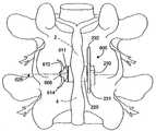
또 다른 실시예로서의 도 4를 참조하면, 본 발명에 따른 임플란트(400)는 제1 결합 요소(engagement element)(상부 후크라고도 함)(480)와 제2 결합 요소(engagement element)(하부 후크라고도 함)(482) 중 하나 또는 둘다를 포함할 수 있다. 일례로, 이와 유사한 후크는 주커만 등에게 허여된 2002년 9월 17일자 미국 특허 제6,451,019호와 주커만 등에게 허여된 2003년 11월 25일자 미국 특허 제6,652,527호에 상세하게 설명되어 있는데, 이들 미국 특허는 본 명세서에 참고로 포함된다. 도 4 및 도 5에 도시된 임플란트(400)는 주 본체(401)에 회전 가능하게 결합된 상부 연결 로드(484)로부터 연장되는 상부 후크(480)와, 주 본체(401)에 회전 가능하게 결합된 하부 연결 로드(486)로부터 연장되는 하부 후크(482)를 포함한다. 선택적으로, 상기 연결 로드(484, 486)는 주 본체(401)에 고정되게 결합된다, 후크(480, 482)는 운동 세그먼트의 극돌간 인대를 표적으로 삼은 운동 세그먼트의 위와 아래로 신연시키기 위한 조직내 도입 확장기로서 역할을 하는 테이퍼진 근위 단부(481, 483)를 포함한다. 주 본체(401)가 인접하는 극돌기들 사이에 위치되면, 상기 상부 및 하부 후크(480, 482)의 테이퍼진 근위 단부(481, 483)들은 마찬가지로 극돌간 인대를 뚫고 그리고/또는 신연시키고, 이에 따라 상부 및 하부 후크(480, 482)는 주 본체(401)가 제위치에 위치되었을 때에 표적으로 삼은 운동 세그먼트의 굽힘 운동을 제한하거나 억제하도록 적절히 위치된다. 도시된 바와 같이, 후크(480, 482)는 연결 로드(484, 486)와 선회 가능하게 결합되고, 이에 따라 후크(480, 482)는 연결 로드(484, 486)에 대해 회전할 수 있고, 이에 의해 의사가 후크(480, 482)와 대응하는 극돌기(2, 4)들 사이의 접촉 및 분산 하중을 향상시킬 수 있게 된다. 회전 가능한 상부 연결 로드(484) 및 하부 연결 로드(486)는 배치 융통성을 제공하고, 이에 따라 해부학적인 것이 환자들 사이에서 변화되고 운동 세그먼트들 사이에서 변화되어 종축(425)에 대한 임플란트(400)의 장축 치수와 단축 치수의 배치가 변화되는 경우에도, 임플란트(400)는 수용될 수 있다.Referring to FIG. 4 as another embodiment, the
도 5는 인접하는 극돌기(2, 4)들 사이에 위치되며 굽힘과 폄이 소망하는 대로 제한되도록 배열된 상부 후크(480) 및 하부 후크(482)를 구비하는 임플란트(400)의 후방측 도면이다. 또한, 제2 윙(460)은 임플란트(400)가 종축(425)을 따라서 운동하는 것을 제하하기 위하여 제2 윙(460)이 전개된다. 상부 후크(480) 및 하부 후크(482)는 삽입 반대 방향으로의 종축(425)을 따르는 운동을 방지하고, 이에 제1 윙이 불필요해진다.FIG. 5 is a rear side view of an
또 다른 실시예로서의 도 6a 및 도 6b를 참조하면, 본 발명에 따른 임플란트(500) 및 그 임플란트(500)를 극돌기들 사이에 위치시키는 방법은 신연 안내부(510)를 포함하고, 상기 신연 안내부(510)의 여러 부분들은 신연 안내부(510)로부터 연장되어서 주 본체(501)의 공동 안에 삽입체(570)를 위치시킴으로써 제2 윙(560)의 상부 작은 날개(512) 및 하부 작은 날개(514) 각각을 형성한다. 이는 작은 날개들에 의해 전체 신연 안내부가 형성된 앞의 실시예와는 대조적인 것이다. 본 실시예에서, 작은 날개(512, 514)는 신연 안내부(510)의 측면 밖으로 연장된다. 도 6a에 도시된 바와 같이 연장되지 않은 경우, 작은 날개(512, 514)는 신연 안내부(510)의 측면을 부분적으로 형성한다. 이와 같은 실시예는6A and 6B as another embodiment, the
전체 신연 안내부(310)가 전개되었을 때에(도 2a 내지 도 3b) 상기한 바와 같이 제2 윙(560)이 임플란트(300, 400)에 대해서 제한된 높이를 갖는 것이 소망되는 경우에 유용한 것으로 생각된다. 일례로, 임플란트(500)가 인접하는 운동 세그먼트들에 위치되는 경우, 일례로 압축 하중이 임플란트(500)에 작용할 때의 신장 운동 중에 임플란트(500)의 제2 윙(560)은 서로 임플란트를 간섭하지 않는 것이 바람직할 수 있다. 이상에서 설명한 바와 같은 임플란트에 의하면, 당업자들이라면 도 6a 및 도 6b의 임플란트(500)의 수많은 각기 다른 변형을 이해할 수 있다. 일례로, 선택적 실시예에서, 상부 작은 날개(512) 및 하부 작은 날개(514)는 약간 다른 형상을 가질 수 있다. 일례로, 인접하는 운동 세그먼트들에 위치된 임플란트(500)가 서로 간섭됨이 없이 보다 용이하게 위치될 수 있도록 하기 위해 상부 작은 날개(512)와 하부 작은 날개(514)를 엇갈리게 위치시킬 수 있다. 이와 같은 엇갈림 배치는 상부 및 하부 극돌기들 중 하나가 다른 것보다 넓은 경우에 있어서의 해부학적인 것을 수용할 수도 있다. 일례로 엇갈림 방식으로 구성하면, 상부 작은 날개(512)는, 하부 작은 날개(514)가 신연 안내부(510) 상에 선회가능하게 장착된 위치에 비해서 신연 단부(511)로부터 작은 거리의 위치에서 신연 안내부(510) 상에 선회 가능하게 장착될 수 있다. 또 다른 실시예에서, 상부 작은 날개(512) 및 하부 작은 날개(514)는 약간 다른 형상을 가질 수 있다.It is thought to be useful when it is desired that the
도 7a 내지 도 8을 참조하면, 본 발명에 따른 임플란트(600)의 또 다른 실시예에 있어서, 주 본체(601)는 제1 윙(630)으로부터 연장되는 중공 중앙 본체(605)(도 7c 및 도 7d에 도시됨)를 포함할 수 있다. 회전 가능한 스페이서(620)가 상기 중공 중앙 본체(605) 둘레에 배치된다. 임플란트(600)는 일례로 도 1b에 도시된 바와 같은 스페이서와 유사한 스페이서(620)를 포함할 수 있다. 신연 안내부(610)는 상기 중공 중앙 본체(605)로부터 연장될 수 있고 상부 작은 날개(612) 및 하부 작은 날개(614)를 포함할 수 있고, 작은 날개들 중 하나 또는 둘다는 신연 안내부(610)의 주 부분(611)과 선회 가능하게 결합될 수 있고, 이에 따라 상부 작은 날개(612) 및/또는 하부 작은 날개(614)는 제2 윙(660)으로서 전개된다. 제2 윙(630)을 전개시키기 위해 핀(606)이 상기 중공 중앙 본체(605) 안으로 삽입된다. 도 7b를 참조하면, 일단 핀(606)이 주 본체(601) 안에 안착되면, 상부 작은 날개(612) 및 하부 작은 날개(614)는 서로에 대해 멀어지게 선회하고, 이에 따라 상부 작은 날개(612) 및 하부 작은 날개(614)가 삽입 반대 방향으로의 종축(625)을 따르는 운동을 제한 또는 차단하게 된다. 따라서 상부 작은 날개(612) 및 하부 작은 날개(614)는 제2 윙(640)으로서 작용한다.7A-8, in another embodiment of the
일 실시예로서의 도 7c 및 도 7d의 부분 단면도를 참조하면, 신연 안내부(610)는 핀(606)을 수용하도록 한 크기로 되어 배열된 컵 구조(616)를 포함한다. 바 구조(618, 619)가 컵 구조(616)와 상부 작은 날개(612) 및 하부 작은 날개(614) 중 하나 또는 둘 사이에 선회가능하게 연결되고, 이에 따라 핀(606)에 의해 컵 구조(616)에 힘이 가해지면, 그 힘은 상부 작은 날개(612) 및 하부 작은 날개(614)에 추가로 전달되고, 이에 의해 상부 작은 날개(612) 및 하부 작은 날개(614)가 신연 안내부(610)의 주 부분(611)과 결합된 힌지(613, 615) 상에서 선회될 수 있고, 이에 따라 제2 윙(660)이 전개된다. 알 수 있는 바와 같이, 상부 작은 날개(612)와 하부 작은 날개(614)의 선회 지점(613, 615)은 바 구조(618, 619)의 장착 지점(617, 619)에 대해서 근위치에 배열되고, 이에 의해 상부 작은 날개(612) 및 하부 작은 날개(614)는, 장착 지점(617, 619)이 핀(606)의 삽입에 의해서 서로 가압될 때에(도 7도 참조), 서로로부터 멀어지게 선회하게 된다. 또 다른 실시예에서, 상부 작은 날개(612) 및 하부 작은 날개(614)는 약간 다른 기구를 이용하여 서로로부터 멀어지게 선회되게 될 수 있다.Referring to the partial cross-sectional views of FIGS. 7C and 7D as one embodiment, the
도 8을 참조하면, 임플란트(600)가 인접하는 극돌기(2, 4)들 사이에 위치된 것으로 도시되어 있다. 도시된 제2 윙(660)은 제1 구성으로(신연 안내부(610)로서) 배열되었을 때에 상부 작은 날개(612) 및 하부 작은 날개(614)가 인접하는 조직 안으로 바람직하지 않게 연장하지 않도록 하는 크기로 되어 있다. 그러나 상부 작은 날개(612) 및 하부 작은 날개(614)는 도 8에 도시된 것과는 다른 크기와 형상으로 형성될 수 있다. 상부 작은 날개(612) 및 하부 작은 날개(614)는 제2 구성으로 배열되었을 때에는 그 상부 작은 날개(612) 및 하부 작은 날개(614)가 삽입 반대 방향으로의 종축(625)을 따르는 운동을 제한 또는 차단하도록 하는 크기와 형상으로만 형성될 필요가 있다.Referring to FIG. 8, the
도 9a 내지 도 9c는 인접하는 극돌기(2, 4)들 사이에 배치된 본 발명에 따른 임플란트(700)의 또 다른 실시예를 예시하고 있는 것이다. 이 실시예에서, 상부 작은 날개(712) 및 하부 작은 날개(714)는 신연 안내부(710) 안에 배치될 수 있으며 캠(707)과 연결되며 결합 가능한 헤드(706)를 구비하는 축을 포함하거나, 혹은 선택적으로는 기어와 같은 어떤 다른 기구를 포함하는 작동기 장치를 작동시킴으로써 전개될 수 있다. 도 9a에서 알 수 있는 바와 같이, 임플란트(700)는 도 3을 참조하여 앞에서 설명한 바와 같이 인접하는 극돌기(2, 4)들 사이에 배치될 수 있다. 임플란트(700)의 신연 안내부(710)는 인접하는 극돌기(2, 4)들 사이에 연결된 극돌간 인대(6)를 뚫고 그리고/또는 신연시키기 위해 사용된다. 이어서 임플란트(700)는 극돌기(2, 4)들 사이에서 가압되고, 이에 따라 신연 안내부(710)는 극돌간 인대(6)를 더 신연시켜서 스페이서(220)가 안에 배치되는 공간을 형성하게 된다. 도시된 본 실시예에서, 스페이서(220)는 임플란트(700)의 제1 윙(230)으로부터 연장되는 중앙 본체를 중심으로 해서 선회할 수 있다. 제1 윙(230)은 삽입 방향으로의 임플란트(700)의 종축(725)을 따르는 운동을 제한 및/또는 차단한다.9A-9C illustrate another embodiment of an
일단 임플란트(700)가 소망하는 대로 배치되면, 작동기 장치(actuator arrangement)가 작동되어서 상부 작은 날개(712) 및 하부 작은 날개(714)를 전개시키고, 이에 의해 도 9c에 도시된 바와 같이 제2 윙(760)이 형성된다. 제2 윙(760)은 삽입 반대 방향으로의 종축(725)을 따르는 운동을 제한 및/또는 차단한다. 제2 윙(760)이 전개되면, 인접하는 극돌기(2, 4)들이 적어도 부분적으로는 윙(730, 760) 사이에 배치되어서, 임플란트(800)가 인접하는 극돌기(2, 4)들 사이의 공간으로부터 바람직하지 않게 이동(dislodge)되는 것을 방직한다. 도 9c에 도시된 바와 같이, 제1 윙(730) 및 제2 윙(760)은, 인접하는 극돌기(2, 4)들이 서로에 대해 약간(예, 비틀림 운동 중에 측방향으로) 이동하여서 환자가 보다 큰 굽힘 운동을 할 수 있도록 하기에 충분히 멀리 떨어지게 배치된다.Once the
도 9b 및 도 9c는 도 9a에 도시된 임플란트(700)의 부분 단면 후방측 도면이다. 일 실시예에서, 전개 가능한 작은 날개(712, 714)는 축(707)과 캠(716)을 포함하는 작동기 장치(actuator arrangement)를 사용하여 신연 안내부(710)로부터 연장될 수 있다. 작은 날개(712, 714)가 신연 안내부(710)로부터 외향으로 선회하도록 캠(716)이 회전하여 작은 날개(712, 714)에 힘을 가한다. 도시된 바와 같이, 작은 날개(712, 714)는 적어도 부분적으로는 신연 안내부(710)의 공동 안에 배치된다.9B and 9C are partial cross-sectional backside views of the
도 10a 내지 도 10e는 인접하는 극돌기(2, 4)들 사이에 배치된 본 발명에 따른 임플란트(800)의 또 다른 실시예를 도시하는 것이다. 이 실시예에서, 상부 작은 날개(812) 및 하부 작은 날개(814)는 신연 안내부(810) 안에 배치될 수 있으며 결합 가능한 헤드(806)를 구비하는 나사(807)이나, 혹은 선택적으로는 기어와 같은 어떤 다른 기구를 포함하는 작동기 장치를 작동시킴으로써 전개될 수 있다. 도 10a에서 알 수 있는 바와 같이, 임플란트(800)는 도 3을 참조하여 앞에서 설명한 바와 같이 극돌기(2, 4)들 사이에 배치된다. 임플란트(800)의 신연 안내부(810)는 인접하는 극돌기(2, 4)들 사이에 연결된 극돌간 인대(6)를 뚫고 그리고/또는 신연시키기 위해 사용된다. 이어서 임플란트(800)는 극돌기(2, 4)들 사이에서 가압되고, 이에 따라 신연 안내부(810)는 극돌간 인대(6)를 더 신연시켜서 스페이서(220)가 안에 배치되는 공간을 형성하게 된다. 도시된 본 실시예에서, 스페이서(220)는 임플란트(800)의 제1 윙(230)으로부터 연장되는 중앙 본체를 중심으로 해서 선회할 수 있다. 제1 윙(230)은 삽입 방향으로의 임플란트(800)의 종축(825)을 따르는 운동을 제한 및/또는 차단한다.10a to 10e show yet another embodiment of an
일단 임플란트(800)가 소망하는 대로 배치되면, 작동기 장치(actuator arrangement)가 작동되어서 상부 작은 날개(812) 및 하부 작은 날개(814)를 전개시키고, 이에 의해 도 9b에 도시된 바와 같이 제2 윙(860)이 형성된다. 제2 윙(860)은 삽입 반대 방향으로의 종축(825)을 따르는 운동을 제한 및/또는 차단한다. 제2 윙(860)이 전개되면, 인접하는 극돌기(2, 4)들이 적어도 부분적으로는 윙(830, 860) 사이에 배치되어서, 임플란트(800)가 인접하는 극돌기(2, 4)들 사이의 공간으로부터 바람직하지 않게 이동(dislodge)되는 것을 방직한다. 도 9b에 도시된 바와 같이, 제1 윙(830) 및 제2 윙(860)은, 인접하는 극돌기(2, 4)들이 서로에 대해 약간(예, 비틀림 운동 중에 측방향으로) 이동하여서 환자가 보다 큰 굽힘 운동을 할 수 있도록 하기에 충분히 멀리 떨어지게 배치된다.Once the
도 10c 및 도 10d는 도 10a 및 도 10b에 도시된 임플란트(800)의 부분 단면 단부도이다. 일 실시예에서, 전개 가능한 작은 날개(812, 814)는 나사(806) 및 나사 형성 칼라(816)를 포함하는 작동기 장치를 이용하여 신연 안내부(810)로부터 연장될 수 있다. 상기 나사 형성 칼라(816)는 작은 날개(812, 814)가 신연 안내부(810)로부터 외향으로 선회하도록 작은 날개(812, 814)에 힘을 가하기 위해 나사(806)를 따라서 구동될 수 있다. 도시된 바와 같이, 작은 날개(812, 814)는 적어도 부분적으로는 신연 안내부(810)의 공동 안에 배치된다. 작은 날개(812, 814)는 상부 선회 지점(817) 및 하부 선회 지점(819)에서 나사 형성 칼라(816)와 선회 가능하게 연결된다. 핀(813, 815) 또는 다른 차단 장치는, 공동 안에 배치되며, 핀(813, 815)이 체결 혹은 전개 위치에서 작은 날개(812, 814)의 배치에 간섭하지 않도록, 배열된다. 그러나 나사 형성 칼라(816)가 후방에서 전방 방향으로 나사(806)를 따라서 이동함에 따라, 작은 날개(812, 814)의 내부 표면들은 핀(813, 815)과 접촉하고, 작은 날개(812, 814)는 신연 안내부(810)로부터 멀리 선회한다. 필요하다면, 작은 날개(812, 814)는 핀(813, 815) 지점들에 대해서 탄성 편의될 수 있고, 이에 따르면 체결된 위치 및 전개된 위치에서 작은 날개(812, 814)는 핀(813, 815) 지점들에 대해 유지되게 된다.10C and 10D are partial cross-sectional end views of the
도 10d 및 도 10e에 도시된 바와 같이, 나사 형성 칼라(816)가 나사(806)를 따라서 일정 거리를 이동하게 되면, 작은 날개(812, 814)가 전개되어서 제2 윙(860)을 형성한다. 작은 날개(812, 814)는 극돌기(2, 4)들의 외부 표면의 유의적인 부분을 따라서 연장한다. 삽입 반대 방향에서의 종축(825)을 따라 가압이 이루어지면, 작은 날개(812, 814)는 인접하는 극돌기(2, 4)들과 접촉하여서 상기 방향으로의 추가 운동에 저항한다. 도 10e는 제2 윙(860)이 전개된 임플란트(800)의 단부도이다. 도시된 바와 같이, 나사 헤드(806)는 신연 안내부(810)로부터 연장지만, 실제로 실시될 때에는 나사 헤드(806)가 신연 안내부(810)의 표면과 동일한 높이를 이루거나 혹은 신연 안내부(810)의 표면에서 약간 멀어지게 할 수 있고, 그에 따르면, 극돌간 인대(6) 및/또는 극돌기(2, 4)들의 신연 중에 임플란트(800)의 운동이 방해 받지 않게 된다. 나사 헤드(806)는 신연 안내부(810)의 근위 단부에 대해 가능한 장치를 설명하기 위해서 신연 안내부(810)로부터 연장하는 것으로 도시되었다.As shown in FIGS. 10D and 10E, when the threaded
도 11a 및 도 11b는 선택적인 작동 장치를 구비하는 임플란트(900)의 또 다른 실시예를 예시하는 것이다. 이 실시예에서, 작은 날개(912, 914)는 반대로 배치될 수 있고, 이에 따르면 작은 날개(912, 914)는 나사 형성 칼라(916)를 나사 헤드(806)를 향하여 가압함으로써 전개된다. 도 12a 및 도 12b는 선택적인 작동 장치를 구비하는 임플란트(1000)의 또 다른 실시예를 예시하는 것이다. 이 실시예에서 작은 날개(1012, 1014)는 2개의 힌지 연결 부분을 포함하고, 각각의 작은 날개(1012, 1014)는 외향으로 접혀져서 제1 윙(1600)의 일부를 형성한다. 제2 윙(1060)은 척주의 축을 따라서 멀리 연장하지 않는다. 즉, 척주를 따르는 제2 윙(1060)의 총 높이는 이전의 실시예에서보다 작다. 제2 윙의 줄어든 높이는 임플란트가 인접하는 운동 세그먼트들에 위치되는 경우에 유리한데, 이에 의하면 인접하는 임플란트들의 바람직하지 않은 접촉을 방지할 수 있다.11A and 11B illustrate another embodiment of an implant 900 having an optional actuating device. In this embodiment, the
이상에서 설명한 바와 같이, 본 발명에 따른 여러 가지 다른 실시예에서, 작은 날개들은 나사 및 나사 형성 칼라가 아닌 다른 기구를 이용하여 신연 안내부로부터 전개시킬 수 있다. 일례로, 하나 이상의 기어를 이용할 수 있다. 더욱이, 또 다른 실시예에서, 상부 작은 날개 및 하부 작은 날개는 도 10a 내지 도 12b에 도시된 형상과는 다른 형상을 가질 수 있다. 본 발명은 이와 같이 도시된 형상을 갖는 작은 날개에 제한되지 않는다. 도 13에 도시된 바와 같은 또 다른 실시예에서, 임플란트(1100)는 상부 작은 날개 및 하부 작은 날개 중 하나만을 포함할 수 있다. 일례로, 임플란트가 인접하는 운동 세그먼트들에 위치되는 경우에는, 하부 작은 날개(814)를 갖는 것이 바람직하고, 이에 의하면 인접하는 임플란트(1100)들의 바람직하지 않은 접촉이 방지된다. 당해 기술 분야의 숙련된 자들에게 자명한 바와 같이, 제2 윙을 형성하는 데에는 수많은 각기 다른 작동 장치가 사용될 수 있다. 본 발명에 따른 임플란트는 본 명세서에 설명된 것에 제한되지 않는다.As described above, in various other embodiments in accordance with the present invention, the small blades may be deployed from the distraction guide using a mechanism other than a screw and a threaded collar. In one example, one or more gears may be used. Moreover, in another embodiment, the upper small wing and the lower small wing can have a shape different from that shown in FIGS. 10A-12B. The present invention is not limited to the small wing having the shape shown as such. In another embodiment as shown in FIG. 13, the
본 발명의 임플란트에 사용하기 위한 재료Materials for Use in Implants of the Invention
어떤 실시예에서, 임플란트 및 그 임플란트의 구성품들(즉, 스페이서, 신연 안내부 등)은 티타늄, 스테인리스강, 코발트 크롬, 및 이들의 합금과 같은 의료 등급의 금속이나, 유사한 고강도 및 생물학적 적합성의 물성을 갖는 기타 적절한 임플란트 재료로 제조될 수 있다. 또한, 임플란트는 적어도 부분적으로는 일례로 티타늄과 니켈의 조합인 니티놀과 같은 형상 기억 금속으로 제조될 수도 있다. 이와 같은 재료들은 통상적으로는 방사선 불투과성이어서 x-선 촬영 및 다른 종류의 촬영 중에 나타난다. 본 발명에 따른 임플란트 및/또는 그 임플란트의 부분들은 다소 가요성 및/또는 편향성 재료로 제조될 수도 있다. 이러한 실시예에서, 임플란트 및/또는 그 임플란트의 부분들은 전체 또는 부분적으로 의료 등급의 생물학적 적합성을 갖는 중합체, 공중합체, 블렌드(blend), 및 중합체의 복합체로 제조될 수 있다. 공중합체는 단량체(monomer)의 하나 이상의 핵종(species)으로부터 유도된 중합이다. 중합체 복합체는 둘 이상의 재료의 이성분 조합(heterogenous combination)인데, 여기서 그 구성 성분들은 혼화되기 쉽지 않고 따라서 서로 간에 계면이 나타난다. 중합체 블렌드는 2 이상의 다른 중합체 핵종의 거시적 동종 혼합물(macroscopically homogenous mixture)이다. 많은 종류의 중합체, 공중합체, 블렌드, 및 중합체의 복합체는 방사선 투과성이어서 x-선 촬영 및 다른 종류의 촬영 중에 나타나지 않는다. 이와 같은 재료들을 포함하는 임플란트는, 완전히 방사선 불투과성 재료를 포함하는 임플란트에 비해서, 척추가 촬영 중일 때에 덜 가려진 시야를 의사에게 제공한다. 그러나 임플란트는 임의의 방사선 투과성 재료를 포함할 필요까지는 없다.In some embodiments, the implant and its components (ie, spacers, distraction guides, etc.) are medical grade metals such as titanium, stainless steel, cobalt chromium, and alloys thereof, but with similar high strength and biocompatibility properties. It can be made of other suitable implant material having a. The implant may also be made of a shape memory metal, such as nitinol, which is at least partly a combination of titanium and nickel. Such materials are typically radiopaque and appear during x-ray imaging and other types of imaging. The implant according to the invention and / or portions of the implant may be made of somewhat flexible and / or deflectable material. In such embodiments, the implant and / or portions of the implant can be made in whole or in part from polymers, copolymers, blends, and composites of polymers of medical grade biocompatibility. Copolymers are polymerisations derived from one or more species of monomer. Polymeric composites are heterogeneous combinations of two or more materials, where the components are not easy to blend and thus interface with each other. The polymer blend is a macroscopically homogenous mixture of two or more different polymer nuclides. Many types of polymers, copolymers, blends, and composites of polymers are radioactive and do not appear during x-ray imaging and other types of imaging. Implants comprising such materials provide the physician with a less obscured field of view when the spine is being imaged, as compared to implants comprising completely radiopaque materials. However, the implant does not need to include any radiation transmissive material.
생물학적 적합성을 갖는 중합체의 한 가지 군은 폴리에테르에테르케톤(PEEK) 및 폴리에테르케톤케톤(PEKK)을 포함하는 여러 멤버를 구비하는 폴리아릴에테르케톤 군이다. PEEK는 임플란트용으로서 내구성 있는 재료로 입증되어서, 생물학적 적합성의 요건에 부합된다. 의료 등급의 PEEK는 영국 랭카셔에 소재하는 빅트렉스 코포레이션(Victrex Corporation)에서 입수할 수 있는데, PEEK-OPTIMA라는 이름의 상품명으로 판매하고 있다. 의료 등급의 PEKK는 OXPEKK라는 상품명으로 판매하고 있는 옥스퍼드 퍼포먼스 머트리얼즈(Oxford Performance Materials)로부터 입수할 수 있고, 또한 BioPEKK라는 상품명으로 판매하고 있는 쿠어스텍(CoorsTek)으로부터 입수할 수 있다. 이들 의료 등급의 재료는 또한 더욱 큰 재료 강도를 나타내는 강화 수지와 같은 강화 폴리머 수지로서 입수가능하기도 하다. 일 실시예에서, 임플란트는 빅트렉스로부터 입수 가능한 의료용 임플란트 이식용으로 입증된 비충진(unfilled) PEEK인 PEEK 450G로 제조될 수 있다. 이와 같은 재료의 다른 공급원으로는 인도 파놀리(Panoli)에 소재하는 가르다(Gharda)가 있다. PEEK 450G는 다음과 같은 대략적 물성을 갖는다.One group of biocompatible polymers is the group of polyaryletherketones having several members including polyetheretherketone (PEEK) and polyetherketoneketone (PEKK). PEEK has proven to be a durable material for implants, meeting the requirements of biocompatibility. Medical grade PEEK is available from Victrex Corporation in Lancashire, UK, and is marketed under the trade name PEEK-OPTIMA. Medical grade PEKK is available from Oxford Performance Materials, sold under the trade name OXPEKK, and also from KororsTek, sold under the name BioPEKK. These medical grade materials are also available as reinforced polymer resins, such as reinforced resins that exhibit greater material strength. In one embodiment, the implant may be made of PEEK 450G, an unfilled PEEK that has been proven for medical implant implants available from Victrex. Another source of such materials is Gharda, Panoli, India. PEEK 450G has the following approximate physical properties.
물성 물성치Property property
밀도 1.3g/ccDensity 1.3g / cc
로크웰 M 99Rockwell M 99
로크웰 R 126Rockwell R 126
인장 강도 97MPaTensile strength 97MPa
탄성 계수 3.5GPaModulus of elasticity 3.5GPa
가요성 계수 4.1GPaFlexibility Factor 4.1GPa
PEEK 450G는 적절한 물리적 및 기계적 물성을 가지며 인접하는 극돌기들 사이의 물리적 하중을 받치고 분산시키는 데 적합하다. 임플란트 및/또는 그 임플란트의 부분들은 압출(extrusion), 사출(injection), 압축(compression) 성형 및/또는 기계 가공 기술에 의해 형성될 수 있다.PEEK 450G has adequate physical and mechanical properties and is suitable for supporting and distributing physical loads between adjacent spinous processes. The implant and / or portions of the implant may be formed by extrusion, injection, compression molding and / or machining techniques.
선택되는 재료는 충진될 수 있음은 주지할 점이다. 충진물은 폴리머 재료를 강화시키기 위해 중합체, 공중합체, 중합체 블렌드, 또는 중합체의 복합체에 추가될 수 있다. 충진재는 기계적, 광학적, 및 열적 특성과 같은 특성을 개질시키기 위해 추가된다. 일례로, 하중 지지 장치용과 같은 특정 용도를 위해서 강도를 향상시키기 위해 폴리머를 기계적으로 강화시키기 위해 탄소 섬유가 추가될 수 있다. 어떤 실시예에서는, 30% 유리-충진 또는 30% 탄소-충진 등급과 같은 기타 등급의 PEEK도 FDA나 다른 관리 기관에 의해 임플란트 이식 가능한 장치의 용도로 분명하게 정해지고 있는 한은 본 발명에 다른 임플란트의 용도로 이용가능하며 의도되기도 한다. 유리-충진 PEEK는 팽창률을 낮추며 비충진 PEEK에 비해 PEEK의 가용성 계수를 증가시킨다. 이것의 최종 제품은 향상된 강도, 강성, 또는 안정성을 위해서 이상적인 것으로 알려져 있다. 탄소-충진 PEEK 향상된 압축 강도와 강성을 가지며 비충진 PEEK에 비해 낮은 팽창률을 갖는 것으로 알려져 있다. 탄소-충진 PEEK는 또한 내마모성을 제공하며 하중지지 성능을 제공한다.It is to be noted that the material selected can be filled. Fills may be added to the polymer, copolymer, polymer blend, or composite of the polymer to reinforce the polymer material. Fillers are added to modify properties such as mechanical, optical, and thermal properties. In one example, carbon fibers may be added to mechanically reinforce the polymer to enhance strength for certain applications, such as for load bearing devices. In some embodiments, other grades of PEEK, such as 30% glass-filled or 30% carbon-filled grades, are also expressly defined by the FDA or other regulatory agencies for use of implantable devices. It is available and intended for use. Glass-filled PEEK lowers the expansion rate and increases the solubility factor of PEEK compared to unfilled PEEK. Its end product is known to be ideal for improved strength, stiffness, or stability. Carbon-filled PEEK is known to have improved compressive strength and stiffness and to have a low expansion rate compared to unfilled PEEK. Carbon-filled PEEK also provides wear resistance and load bearing performance.
이해할 수 있는 바와 같이,As you can understand,
피로 저항성을 가지며 양호한 기억성을 가지며 가요성이며 그리고/또는 편향성을 가지며 아주 낮은 흡습성을 가지며 양호한 내마모성 및/또는 내마멸성을 갖는, 다른 적절한 유사하게 생물학적 적합이 있는 열가소성 또는 열가소성 폴리콘덴세이트(polycondensate)도 본 발명이 범주를 벗어남이 없이 사용될 수 있다. 설명한 바와 같이, 임플란트는 폴리에테르케톤케톤(PEEK)으로 구성될 수 있다. 사용될 수 있는 다른 재료로는 폴리에테르케톤(PEK), 폴리에테르케톤에테르케톤케톤(PEKEKK), 폴리에테르에테르케톤케톤(PEEKK)이 있으며, 일반적으로 폴리아릴에테르에테르케톤이 있다. 또한, 다른 열사소성 재료뿐만 아니라 다른 케톤도 사용될 수 있다. 임플란트에서 사용될 수 있는 적절한 폴리머에 대한 참조 문헌은 다음과 같고, 이들 문헌은 본 명세서에 참고로 포함한다. 상기 참조 문헌으로는, 발명의 명칭이 "생물학적 적합성 폴리머 재료"인 2002년 1월 10일자 국제특허공개 WO 02/02158A1호, 발명의 명칭이 "생물학적 적합성 폴리머 재료"인 2002년 1월 3일자 국제특허공개 WO 02/00275A1호, 그리고 발명의 명칭이 "생물학적 적합성 폴리머 재료"인 2002년 1월 3일자 국제특허공개 WO 02/00270A1이 있다.Other suitable similarly biocompatible thermoplastics or thermoplastic polycondensates that are fatigue resistant, good memory, flexible, and / or deflectable, have very low hygroscopicity and have good abrasion and / or abrasion resistance. The invention can be used without departing from the scope. As described, the implant may be comprised of polyetherketoneketone (PEEK). Other materials that may be used include polyether ketones (PEK), polyether ketone ether ketone ketones (PEKEKK), polyether ether ketone ketones (PEEKK), and polyaryl ether ether ketones in general. In addition, other ketones may be used as well as other thermoplastics. References to suitable polymers that can be used in the implants are as follows, which are incorporated herein by reference. See, for example, International Patent Publication No. WO 02 / 02158A1, January 10, 2002, entitled "Biologically Compatible Polymer Material," International Publication, January 3, 2002, entitled "Biocompatible Polymer Material." Patent Publication WO 02 / 00275A1, and International Patent Publication WO 02 / 00270A1, filed January 3, 2002, entitled “Biocompatible Polymeric Materials”.
미국 캘리포니아 버클리에 소재하는 폴리머 테크놀로지 그룹(Polymer Technology Group)에서 입수 가능한 바이오네이트(Bionate: 등록 상표명)라는 상표명의 폴리카보네이트 우레탄과 같은 다른 재료도 적절할 수 있는데, 그 이유는 양호한 산화 안정성, 생물학적 적합성, 기계적 강도 및 내흡습성이 있기 때문이다. 다른 열가소성 재료 및 다른 고 분자량 폴리머도 사용할 수 있다.Other materials, such as the polycarbonate urethane trademarked under the trade name Biopolymer, available from the Polymer Technology Group, Berkeley, California, may also be suitable because of good oxidative stability, biocompatibility, This is because there is mechanical strength and hygroscopic resistance. Other thermoplastic materials and other high molecular weight polymers may also be used.
극돌간 임플란트를 이식하는 방법How to implant a spinous stone implant
도 2a 내지 도 8에 도시된 임플란트(300)를 경부 척주 안에 최소 침투성 외과술적으로 이식하는 방법을 여기에 개시하고 교시한다. 본 방법에 있어서, 도 14에 도시된 바와 같이, 바람직하기로는 안내 와이어(780)가 배치용 그물코(placement network)(790)를 통해서 임플란트 수용자의 목 안으로 삽입한다. 안내 와이어(780)는 임플란트(300)가 극돌기들을 포함하는 경부 척주에 대해서 배치되는 곳에 위치시키기 위해 사용된다. 일단 안내 와이어(780)가 촬영 기술의 도움을 받아 위치되면, 목의 측면 상에서 절개가 행해지고, 그에 따라 본 발명에 따른 임플란트(300)가 절개부를 통해서 안내 와이어(780)에 대해 대략 수직이고 안내 와이어(780)의 단부에 향한 선을 따라서 목 안으로 위치된다. 임플란트(300)의 주 본체(301)가 환자의 목 안으로 삽입된다. 바람직하기로는, 삽입 중에, 신연 안내부(310)는 조직을 절개함이 없이 조직을 뚫거나 분리시킨다.Disclosed and taught herein is a method of minimally invasive surgical implantation of the
일단 주 본체(301)가 만족스럽게 위치되면, 주 본체(301)의 공동 안에 삽입체(370)가 위치되고, 이에 의해 주 본체(301)의 신연 안내부(310)가 제2 구성으로 배열되고, 그에 따라 신연 안내부(310)의 적어도 일부가 제2 윙을 형성한다. 삽입체(370)는 이 삽입체(370)가 위에 삽입되는 선과 대체로 동일 직선인 선을 따라서 삽입된다. 목의 해부학은 주 본체(301) 및 삽입체(370)에 대해서 측면으로부터 목으로 들어갈 수 있도록 하기에 가장 편리하고 최소 침투적이도록 되어 있다.Once the
또한, 도 2a 내지 도 8d에 설명된 임플란트(300)를 허리 척추에 최소 침투적인 외과술적으로 이식하는 방법에 대해서 여기에 개시하고 교시한다. 본 방법에 있어서는, 도 15a의 흐름도에 도시한 바와 같이, 바람지하기로는 후방에서-전방으로의 접근을 이용하여 편면 절개(unilateral incision)를 하는 것이 좋다(단계 102). 편면 절개는 일례로 극돌기들을 따르는 축의 좌측으로 소정의 거리 위치에서 한다. 절개부 및 개구를 확대하고, 신연 공구가 절개부 안에 위치되고, 이에 따라 신연 공구의 근위 단부가 극돌간 인대의 노출측으로 접근할 수 있다(단계 104). 신연 공구는 극돌간 인대를 관통하여 가압되고, 이에 의해 임플란트를 받아들일 수 있도록 극돌간 인대가 신연된다(단계 106). 일단 극돌간 인대가 충분히 신연되면, 신연 공구는 절개부로부터 풀려나와 제거된다(단계 108).Also disclosed and taught herein is a method of minimally invasive surgical implantation of the
일단 신연 공구가 절개부로부터 제거되면, 임플란트는 넓혀진 개구에 위치되고, 임플란트의 신연 안내부는 넓혀진 개구를 관통하여 가압된다(단계 110). 또한 임플란트는 스페이서가 표적으로 삼은 운동 세그먼트의 인접하는 극돌기들 사이에 소망하는 대로 위치될 때까지 개구를 관통하여 가압된다(단계 112). 스페이서는 하중이 극돌기들의 표면 위에서 더욱 균일하게 분포될 수 있도록 자유롭게 회전된다. 선택적으로, 임플란트는 제1 윙이 인접하는 극돌기들과 접촉하게 될 때까지 넓혀진 개구를 통하여 가압되고, 이에 의해 삽입 방향으로의 추가 운동이 차단된다. 임플란트가 일단 적절히 배열되면, 삽입체는 임플란트의 원위 단부에 위치되고, 이에 따라 삽입체는 중공 중앙 본체의 중공 공동을 통해서 그 안으로 가압된다(단계 114). 삽입체가 공동의 내측에 안착되면, 신연 안내부가 분할하여서, 상부 작은 날개와 하부 작은 날개가 윙으로서 전개된다. 나머지 공구들이 절개부로부터 제거되고서, 절개부가 닫혀진다(단계 116). 바람직하기로는 절개 중에 신연 단부는 조직을 절개함이 없이 조직을 뚫거나 분리시키는 것이 좋다.Once the distraction tool is removed from the incision, the implant is positioned in the widened opening, and the distal guide of the implant is pressed through the widened opening (step 110). The implant is also pressed through the opening until the spacer is positioned as desired between adjacent spinous processes of the targeted motion segment (step 112). The spacer is freely rotated so that the load can be distributed more evenly on the surface of the spinous processes. Optionally, the implant is pressed through the widened opening until the first wing comes into contact with adjacent spinous processes, thereby blocking further movement in the insertion direction. Once the implant is properly arranged, the insert is positioned at the distal end of the implant, whereby the insert is pressed into it through the hollow cavity of the hollow central body (step 114). When the insert is seated inside the cavity, the distraction guide splits so that the upper small wing and the lower small wing develop as wings. The remaining tools are removed from the incision and the incision is closed (step 116). Preferably, during dissection, the distal end is able to penetrate or separate the tissue without incision.
또한, 도 9a 내지 도 13에 설명된 임플란트를 허리 척추에 최소 침투적인 외과술적으로 이식하는 방법에 대해서 여기에 개시하고 교시한다. 본 방법에 있어서는, 도 15b의 흐름도에 도시한 바와 같이, 후방에서-전방으로의 접근을 이용하여 절개 혹은 개구를 한다(단계 202). 절개 또는 개구가 확대되고, 신연 공구가 절개부 안에 위치되고, 이에 따라 신연 공구의 근위 단부가 극돌간 인대의 노출측으로 접근할 수 있다(단계 204). 신연 공구는 극돌간 인대를 관통하여 가압되고 신연되고, 이에 의해 임플란트를 받아들일 수 있도록 극돌간 인대가 신연된다(단계 206). 일단 극돌간 인대가 충분히 신연되면, 신연 공구는 절개부로부터 풀려나와 제거된다(단계 208).Also disclosed and taught herein is a method of minimally invasive surgical implantation of the implant described in FIGS. 9A-13. In this method, as shown in the flow chart of FIG. 15B, an incision or opening is made using access from the back to the front (step 202). The incision or opening is enlarged and the distraction tool is positioned in the incision, so that the proximal end of the distraction tool can approach the exposed side of the interlucent ligament (step 204). The distraction tool is pressed and stretched through the interultra ligament, whereby the interultra ligament is stretched to receive the implant (step 206). Once the intervertebral ligament is sufficiently stretched, the stretching tool is released from the incision and removed (step 208).
일단 신연 공구가 절개부로부터 제거되면, 임플란트는 넓혀진 개구에 위치되고, 임플란트의 신연 안내부는 넓혀진 개구를 관통하여 가압된다(단계 210). 또한 임플란트는 스페이서가 표적으로 삼은 운동 세그먼트의 인접하는 극돌기들 사이에 소망하는 대로 위치될 때까지 개구를 관통하여 가압된다(단계 212). 스페이서는 하중이 극돌기들의 표면 위에서 더욱 균일하게 분포될 수 있도록 자유롭게 회전된다. 선택적으로, 임플란트는 제1 윙이 인접하는 극돌기들과 접촉하게 될 때까지 넓혀진 개구를 통하여 가압되고, 이에 의해 삽입 방향으로의 추가 운동이 차단된다. 임플란트가 일단 적절히 배열되면, 작동 공구가 인접하는 극돌기들의 반대측에 있는 절개부 안에 삽입 지점으로부터 삽입된다(단계 214). 작동 공구는 작동 장치와 결합할 수 있고 작동 장치를 작동시킬 수 있으며, 이에 따라 상부 작은 날개 및 하부 작은 날개가 앞에서 설명한 바와 같이 제2 윙으로서 전개된다(단계 216). 나머지 공구들이 절개부로부터 제거되고서, 절개부가 닫혀진다(단계 218). 바람직하기로는 절개 중에 신연 단부는 조직을 절개함이 없이 조직을 뚫거나 분리시키는 것이 좋다.Once the distraction tool is removed from the incision, the implant is positioned in the widened opening, and the distal guide of the implant is pressed through the widened opening (step 210). The implant is also pressed through the opening until the spacer is positioned as desired between adjacent spinous processes of the targeted movement segment (step 212). The spacer is freely rotated so that the load can be distributed more evenly on the surface of the spinous processes. Optionally, the implant is pressed through the widened opening until the first wing comes into contact with adjacent spinous processes, thereby blocking further movement in the insertion direction. Once the implant is properly arranged, the actuation tool is inserted from the insertion point into the incision on the opposite side of the adjacent spinous processes (step 214). The actuating tool can engage the actuating device and actuate the actuating device such that the upper small wing and the lower small wing are deployed as the second wing as described above (step 216). The remaining tools are removed from the incision and the incision is closed (step 218). Preferably, during dissection, the distal end is able to penetrate or separate the tissue without incision.
도 1a는 눈물 모양 형상의 단면을 갖는 스페이서, 신연 안내부, 제1 윙, 및 상기 신연 안내부에 연결 가능한 제2 윙을 포함하는 임플란트의 사시도이다.1A is a perspective view of an implant including a spacer having a teardrop-shaped cross section, a distraction guide, a first wing, and a second wing connectable to the distraction guide;
도 1b는 타원형 형상의 단면을 갖는 회전 가능한 스페이서, 신연 안내부, 제 1 윙, 및 상기 신연 안내부에 연결 가능한 제2 윙을 포함하는 임플란트의 사시도이다.FIG. 1B is a perspective view of an implant comprising a rotatable spacer having an elliptical cross section, a distraction guide, a first wing, and a second wing connectable to the distraction guide.
도 2a는 주 본체 및 삽입체를 포함하고, 상기 주 본체는 신연 안내부, 스페이서, 제1 윙을 구비하는 구성으로 된, 본 발명에 따른 임플란트의 사시도이다.FIG. 2A is a perspective view of an implant according to the invention comprising a main body and an insert, the main body having a distraction guide, a spacer and a first wing. FIG.
도 2b는 삽입체가 주 본체 안에 위치되어 있고, 이에 의해 임플란트가 인접하는 극돌기들 사이에 위치되었을 때에 그 임플란트의 운동을 상기 주 본체에 결합된 신연 안내부가 제한하거나 차단하는, 도 2a의 임플란트의 사시도이다.FIG. 2B is a perspective view of the implant of FIG. 2A, wherein the insert is located within the main body, thereby limiting or blocking movement of the implant when the implant is located between adjacent spinous processes. to be.
도 3a는 인접하는 극돌기들 사이에 도 2a 및 도 2b의 임플란트의 주 본체가 위치되어 있는 상태의 측면도이다.3A is a side view of a state where the main body of the implant of FIGS. 2A and 2B is located between adjacent spinous processes.
도 3b는 삽입체가 주 본체 안에 위치되어 있는 도 3a의 임플란트의 측면도이다.3B is a side view of the implant of FIG. 3A with the insert positioned in the main body.
도 4는 굽힘 동작 중에 인접하는 극돌기들의 상대 운동을 제한하기 위한 후크를 주 본체가 포함하고 있는 선택적인 실시예에 따른 임플란트의 사시도이다.4 is a perspective view of an implant according to an alternative embodiment in which the main body includes a hook for limiting relative movement of adjacent spinous processes during a bending operation.
도 5는 인접하는 극돌기들 사이에 위치되고 배열되어서 후크가 인접하는 극돌기들을 제한하는 도 4의 임플란트의 측면도이다.FIG. 5 is a side view of the implant of FIG. 4 positioned and arranged between adjacent spinous processes so that the hook restricts adjacent spinous processes.
도 6a는 신연 안내부의 제1 부분 및 제2 부분이 전개되어서 제2 윙을 형성하는, 본 발명에 따른 임플란트의 또 다른 실시예의 사시도이다.6A is a perspective view of another embodiment of an implant according to the present invention in which the first and second portions of the distraction guide are deployed to form a second wing.
도 6b는 삽입체가 주 본체 안에 위치되고 이에 의해 신연 안내부의 제1 부분 및 제2 부분이 전개되는 구성인, 도 6a의 임플란트의 사시도이다.FIG. 6B is a perspective view of the implant of FIG. 6A, wherein the insert is positioned in the main body whereby the first and second portions of the distal guide are developed. FIG.
도 7a는 회전 가능한 스페이서를 포함하는 본 발명에 따른 임플란트의 또 다 른 실시예의 사시도이다.7A is a perspective view of another embodiment of an implant according to the present invention comprising a rotatable spacer.
도 7b는 삽입체가 중앙 본체 안에 위치되고 이에 따라 신연 안내부가 제2 윙으로서 전개되는, 도 7a의 임플란트의 사시도이다.FIG. 7B is a perspective view of the implant of FIG. 7A with the insert positioned in the central body and thus the distal guide deployed as the second wing. FIG.
도 7c는 도 7a의 신연 안내부의 측단면도이다.FIG. 7C is a side cross-sectional view of the distraction guide of FIG. 7A. FIG.
도 7d는 도 7b의 신연 안내부의 측단면도이다.FIG. 7D is a side cross-sectional view of the distraction guide of FIG. 7B. FIG.
도 8은 인접하는 극돌기들 사이에 위치된 도 7a 내지 도 7d의 임플란트의 측면도이다.8 is a side view of the implant of FIGS. 7A-7D positioned between adjacent spinous processes.
도 9a는 인접하는 극돌기들 사이에 위치된 임플란트의 선택적인 실시예의 측면도이다.9A is a side view of an alternative embodiment of an implant located between adjacent spinous processes.
도 9b는 전개 가능한 작은 날개가 임플란트의 신연 안내부 안에 배치된 것을 도시하는 도 9a의 임플란트의 부분 단면 측면도이다.FIG. 9B is a partial cross-sectional side view of the implant of FIG. 9A showing that the deployable small wing is disposed within the distal guide of the implant.
도 9c는 작은 날개가 전개되어 있는 도 9b의 임플란트의 부분 단면 측면도이다.FIG. 9C is a partial cross-sectional side view of the implant of FIG. 9B with a small wing deployed. FIG.
도 10a는 인접하는 극돌기들 사이에 위치된 임플란트의 선택적인 실시예의 측면도이다.10A is a side view of an alternative embodiment of an implant located between adjacent spinous processes.
도 10b는 작은 날개가 전개되어 있고 인접하는 극돌기들 사이에 위치된 도 10a의 임플란트의 측면도이다.FIG. 10B is a side view of the implant of FIG. 10A with the small wings deployed and positioned between adjacent spinous processes.
도 10c는 전개 가능한 작은 날개가 임플란트의 신연 안내부 내에 배치된 것을 도시하는 도 10a의 임플란트의 부분 단면 측면도이다.FIG. 10C is a partial cross-sectional side view of the implant of FIG. 10A showing that the deployable small wing is disposed within the distal guide of the implant.
도 10d는 작은 날개가 임플란트의 신연 안내부로부터 연장되도록 작은 날개 가 전개된 것을 보이는 도 10a 내지 도 10c의 임플란트의 부분 단면 단부도이다.10D is a partial cross-sectional end view of the implant of FIGS. 10A-10C showing the small wings deployed such that the small wings extend from the distal guide of the implant.
도 10e는 신연 안내부와 상기 신연 안내부에 대해 전개된 작은 날개를 보이는 도 10a 내지 도 10d의 임플란트의 단부도이다.FIG. 10E is an end view of the implant of FIGS. 10A-10D showing the distraction guide and the small wings deployed relative to the distraction guide.
도 11a는 선택적인 작동기 장치를 포함하는 본 발명에 따른 임플란트의 선택적인 실시예의 부분 단면 단부도이다.11A is a partial cross-sectional end view of an alternative embodiment of an implant according to the present invention that includes an optional actuator device.
도 11b는 작은 날개가 임플란트의 신연 안내부로부터 연장되도록 작은 날개가 전개된 것을 보이는 도 11a의 임플란트의 부분 단면 단부도이다.FIG. 11B is a partial cross-sectional end view of the implant of FIG. 11A showing the small wings deployed such that the small wings extend from the distal guide of the implant.
도 12a는 작은 날개가 2개의 힌지 연결 부분을 포함하는 선택적인 작동기 장치를 구비하는 본 발명에 따른 임플란트의 또 다른 실시예의 부분 단면 단부도이다.12A is a partial cross-sectional end view of another embodiment of an implant according to the present invention in which a small wing comprises an optional actuator device comprising two hinged portions.
도 12b는 작은 날개가 임플란트의 신연 안내부로부터 연장되도록 작은 날개가 전개된 것을 보이는 도 12a의 임플란트의 부분 단면 단부도이다.FIG. 12B is a partial cross-sectional end view of the implant of FIG. 12A showing the small wing deployed such that the small wing extends from the distal guide of the implant.
도 13은 임플란트가 인접하는 운동 세그먼트들에 배치되어 있는 본 발명에 따른 임플란트의 또 다른 실시예의 부분 단면 단부도이다.13 is a partial cross-sectional end view of another embodiment of an implant according to the present invention in which the implant is disposed in adjacent motion segments.
도 14는 본 발명에 따라서 인접하는 극돌기들 사이에 도 2a 내지 도 8의 임플란트를 이식하는 방법의 일 실시예를 보이는 도면이다.14 shows one embodiment of a method for implanting the implant of FIGS. 2A-8 between adjacent spinous processes in accordance with the present invention.
도 15a는 본 발명에 따라서 인접하는 극돌기들 사이에 도 2a 내지 도 8의 극돌간 임플란트를 이식하는 방법의 일 실시예를 예시하는 도면이다.FIG. 15A is a diagram illustrating one embodiment of a method of implanting the intervertebral implant of FIGS. 2A-8 between adjacent spinous processes in accordance with the present invention.
도 15b는 본 발명에 따라서 인접하는 극돌기들 사이에 도 9a 내지 도 13의 극돌간 임플란트를 이식하는 방법의 일 실시예를 예시하는 도면이다.FIG. 15B is a diagram illustrating one embodiment of a method of implanting the intervertebral implant of FIGS. 9A-13 between adjacent spinous processes in accordance with the present invention.
이상에서의 본 발명에 대한 설명은 예시하고 설명하기 위한 목적으로 제공된 것이다. 개시된 세밀한 형태에서 본 발명을 구명(究明)하거나 제한하고자 한 것이 아니다. 당해 기술 분야의 숙련된 자들에게는 여러 가지의 수정 및 변형은 자명한 것이다. 여러 실시예들은 본 발명의 원리 및 그 실제 적용을 가장 잘 설명하기 위하여 선택되고 설명된 것으로, 이에 의하면 당업자들이라면 여러 가지 변형례를 갖는 여러 실시예를 위한 본 발명은 특정 용도에 적합한 것으로 의도된 것임을 이해할 수 있다. 본 발명의 범위는 특허청구범위 및 그 균등물에 의해 정의된다.The description of the present invention above is provided for the purpose of illustration and description. It is not intended to be exhaustive or to limit the invention to the precise form disclosed. Many modifications and variations are apparent to those skilled in the art. Various embodiments have been selected and described in order to best explain the principles of the present invention and its practical application, which will enable those skilled in the art to make the invention suitable for a particular use in various embodiments with various modifications. I can understand. The scope of the invention is defined by the claims and their equivalents.
Claims (20)
Translated fromKoreanApplications Claiming Priority (12)
| Application Number | Priority Date | Filing Date | Title |
|---|---|---|---|
| US66388505P | 2005-03-21 | 2005-03-21 | |
| US66391805P | 2005-03-21 | 2005-03-21 | |
| US60/663,885 | 2005-03-21 | ||
| US60/663,918 | 2005-03-21 | ||
| US66407605P | 2005-03-22 | 2005-03-22 | |
| US60/664,076 | 2005-03-22 | ||
| US11/378,108 | 2006-03-17 | ||
| US11/377,971US7931674B2 (en) | 2005-03-21 | 2006-03-17 | Interspinous process implant having deployable wing and method of implantation |
| US11/378,108US7749252B2 (en) | 2005-03-21 | 2006-03-17 | Interspinous process implant having deployable wing and method of implantation |
| US11/378,894US20060271194A1 (en) | 2005-03-22 | 2006-03-17 | Interspinous process implant having deployable wing as an adjunct to spinal fusion and method of implantation |
| US11/377,971 | 2006-03-17 | ||
| US11/378,894 | 2006-03-17 |
Publications (1)
| Publication Number | Publication Date |
|---|---|
| KR20080031852Atrue KR20080031852A (en) | 2008-04-11 |
Family
ID=39642007
Family Applications (1)
| Application Number | Title | Priority Date | Filing Date |
|---|---|---|---|
| KR1020077024296ACeasedKR20080031852A (en) | 2005-03-21 | 2006-03-21 | Spinous process implant with deployable wings and implant implantation method |
Country Status (6)
| Country | Link |
|---|---|
| US (3) | US7931674B2 (en) |
| EP (1) | EP1861046B1 (en) |
| KR (1) | KR20080031852A (en) |
| AU (1) | AU2006227185A1 (en) |
| CA (1) | CA2599459A1 (en) |
| WO (1) | WO2006102269A2 (en) |
Cited By (1)
| Publication number | Priority date | Publication date | Assignee | Title |
|---|---|---|---|---|
| KR101380682B1 (en)* | 2006-04-07 | 2014-04-02 | 바이오메드 엘티디. | Implant for Supporting Spinous Processes |
Families Citing this family (301)
| Publication number | Priority date | Publication date | Assignee | Title |
|---|---|---|---|---|
| US7201751B2 (en) | 1997-01-02 | 2007-04-10 | St. Francis Medical Technologies, Inc. | Supplemental spine fixation device |
| US20050245937A1 (en)* | 2004-04-28 | 2005-11-03 | St. Francis Medical Technologies, Inc. | System and method for insertion of an interspinous process implant that is rotatable in order to retain the implant relative to the spinous processes |
| US20080039859A1 (en) | 1997-01-02 | 2008-02-14 | Zucherman James F | Spine distraction implant and method |
| US6068630A (en)* | 1997-01-02 | 2000-05-30 | St. Francis Medical Technologies, Inc. | Spine distraction implant |
| US20080086212A1 (en) | 1997-01-02 | 2008-04-10 | St. Francis Medical Technologies, Inc. | Spine distraction implant |
| US7959652B2 (en)* | 2005-04-18 | 2011-06-14 | Kyphon Sarl | Interspinous process implant having deployable wings and method of implantation |
| US7306628B2 (en) | 2002-10-29 | 2007-12-11 | St. Francis Medical Technologies | Interspinous process apparatus and method with a selectably expandable spacer |
| US8128661B2 (en) | 1997-01-02 | 2012-03-06 | Kyphon Sarl | Interspinous process distraction system and method with positionable wing and method |
| US5836948A (en)* | 1997-01-02 | 1998-11-17 | Saint Francis Medical Technologies, Llc | Spine distraction implant and method |
| US20080071378A1 (en)* | 1997-01-02 | 2008-03-20 | Zucherman James F | Spine distraction implant and method |
| FR2897259B1 (en) | 2006-02-15 | 2008-05-09 | Ldr Medical Soc Par Actions Si | INTERSOMATIC TRANSFORAMINAL CAGE WITH INTERBREBAL FUSION GRAFT AND CAGE IMPLANTATION INSTRUMENT |
| US8114163B2 (en) | 2000-04-10 | 2012-02-14 | Biomet Manufacturing Corp. | Method and apparatus for adjusting height and angle for a radial head |
| US8920509B2 (en) | 2000-04-10 | 2014-12-30 | Biomet Manufacturing, Llc | Modular radial head prosthesis |
| US8535382B2 (en) | 2000-04-10 | 2013-09-17 | Biomet Manufacturing, Llc | Modular radial head prostheses |
| FR2824261B1 (en) | 2001-05-04 | 2004-05-28 | Ldr Medical | INTERVERTEBRAL DISC PROSTHESIS AND IMPLEMENTATION METHOD AND TOOLS |
| FR2827156B1 (en) | 2001-07-13 | 2003-11-14 | Ldr Medical | VERTEBRAL CAGE DEVICE WITH MODULAR FASTENING |
| FR2844179B1 (en) | 2002-09-10 | 2004-12-03 | Jean Taylor | POSTERIOR VERTEBRAL SUPPORT KIT |
| US20060264939A1 (en)* | 2003-05-22 | 2006-11-23 | St. Francis Medical Technologies, Inc. | Interspinous process implant with slide-in distraction piece and method of implantation |
| US7909853B2 (en) | 2004-09-23 | 2011-03-22 | Kyphon Sarl | Interspinous process implant including a binder and method of implantation |
| US8147548B2 (en) | 2005-03-21 | 2012-04-03 | Kyphon Sarl | Interspinous process implant having a thread-shaped wing and method of implantation |
| US7549999B2 (en) | 2003-05-22 | 2009-06-23 | Kyphon Sarl | Interspinous process distraction implant and method of implantation |
| US7833246B2 (en) | 2002-10-29 | 2010-11-16 | Kyphon SÀRL | Interspinous process and sacrum implant and method |
| US8048117B2 (en)* | 2003-05-22 | 2011-11-01 | Kyphon Sarl | Interspinous process implant and method of implantation |
| US20080021468A1 (en)* | 2002-10-29 | 2008-01-24 | Zucherman James F | Interspinous process implants and methods of use |
| US8070778B2 (en) | 2003-05-22 | 2011-12-06 | Kyphon Sarl | Interspinous process implant with slide-in distraction piece and method of implantation |
| US7931674B2 (en) | 2005-03-21 | 2011-04-26 | Kyphon Sarl | Interspinous process implant having deployable wing and method of implantation |
| FR2846550B1 (en) | 2002-11-05 | 2006-01-13 | Ldr Medical | INTERVERTEBRAL DISC PROSTHESIS |
| US7335203B2 (en)* | 2003-02-12 | 2008-02-26 | Kyphon Inc. | System and method for immobilizing adjacent spinous processes |
| US7255714B2 (en) | 2003-09-30 | 2007-08-14 | Michel H. Malek | Vertically adjustable intervertebral disc prosthesis |
| BR0318590A (en)* | 2003-10-30 | 2006-10-17 | Synthes Gmbh | interspinous implant |
| US7862586B2 (en) | 2003-11-25 | 2011-01-04 | Life Spine, Inc. | Spinal stabilization systems |
| FR2865629B1 (en) | 2004-02-04 | 2007-01-26 | Ldr Medical | INTERVERTEBRAL DISC PROSTHESIS |
| EP2113227B1 (en) | 2004-02-04 | 2015-07-29 | LDR Medical | Intervertebral disc prosthesis |
| FR2869528B1 (en) | 2004-04-28 | 2007-02-02 | Ldr Medical | INTERVERTEBRAL DISC PROSTHESIS |
| US7585316B2 (en) | 2004-05-21 | 2009-09-08 | Warsaw Orthopedic, Inc. | Interspinous spacer |
| US8012209B2 (en) | 2004-09-23 | 2011-09-06 | Kyphon Sarl | Interspinous process implant including a binder, binder aligner and method of implantation |
| US8425559B2 (en) | 2004-10-20 | 2013-04-23 | Vertiflex, Inc. | Systems and methods for posterior dynamic stabilization of the spine |
| US8123807B2 (en) | 2004-10-20 | 2012-02-28 | Vertiflex, Inc. | Systems and methods for posterior dynamic stabilization of the spine |
| US8012207B2 (en) | 2004-10-20 | 2011-09-06 | Vertiflex, Inc. | Systems and methods for posterior dynamic stabilization of the spine |
| US9023084B2 (en) | 2004-10-20 | 2015-05-05 | The Board Of Trustees Of The Leland Stanford Junior University | Systems and methods for stabilizing the motion or adjusting the position of the spine |
| US9161783B2 (en)* | 2004-10-20 | 2015-10-20 | Vertiflex, Inc. | Interspinous spacer |
| US8613747B2 (en) | 2004-10-20 | 2013-12-24 | Vertiflex, Inc. | Spacer insertion instrument |
| US9119680B2 (en) | 2004-10-20 | 2015-09-01 | Vertiflex, Inc. | Interspinous spacer |
| US8123782B2 (en) | 2004-10-20 | 2012-02-28 | Vertiflex, Inc. | Interspinous spacer |
| US8152837B2 (en) | 2004-10-20 | 2012-04-10 | The Board Of Trustees Of The Leland Stanford Junior University | Systems and methods for posterior dynamic stabilization of the spine |
| US8277488B2 (en)* | 2004-10-20 | 2012-10-02 | Vertiflex, Inc. | Interspinous spacer |
| US7763074B2 (en)* | 2004-10-20 | 2010-07-27 | The Board Of Trustees Of The Leland Stanford Junior University | Systems and methods for posterior dynamic stabilization of the spine |
| US8128662B2 (en) | 2004-10-20 | 2012-03-06 | Vertiflex, Inc. | Minimally invasive tooling for delivery of interspinous spacer |
| US8317864B2 (en) | 2004-10-20 | 2012-11-27 | The Board Of Trustees Of The Leland Stanford Junior University | Systems and methods for posterior dynamic stabilization of the spine |
| US8945183B2 (en)* | 2004-10-20 | 2015-02-03 | Vertiflex, Inc. | Interspinous process spacer instrument system with deployment indicator |
| US8273108B2 (en) | 2004-10-20 | 2012-09-25 | Vertiflex, Inc. | Interspinous spacer |
| US8167944B2 (en) | 2004-10-20 | 2012-05-01 | The Board Of Trustees Of The Leland Stanford Junior University | Systems and methods for posterior dynamic stabilization of the spine |
| US8409282B2 (en) | 2004-10-20 | 2013-04-02 | Vertiflex, Inc. | Systems and methods for posterior dynamic stabilization of the spine |
| US8241330B2 (en)* | 2007-01-11 | 2012-08-14 | Lanx, Inc. | Spinous process implants and associated methods |
| US9055981B2 (en) | 2004-10-25 | 2015-06-16 | Lanx, Inc. | Spinal implants and methods |
| US8597360B2 (en)* | 2004-11-03 | 2013-12-03 | Neuropro Technologies, Inc. | Bone fusion device |
| WO2006058221A2 (en) | 2004-11-24 | 2006-06-01 | Abdou Samy M | Devices and methods for inter-vertebral orthopedic device placement |
| EP2219538B1 (en)* | 2004-12-06 | 2022-07-06 | Vertiflex, Inc. | Spacer insertion instrument |
| FR2879436B1 (en) | 2004-12-22 | 2007-03-09 | Ldr Medical | INTERVERTEBRAL DISC PROSTHESIS |
| US8029567B2 (en)* | 2005-02-17 | 2011-10-04 | Kyphon Sarl | Percutaneous spinal implants and methods |
| US7998208B2 (en) | 2005-02-17 | 2011-08-16 | Kyphon Sarl | Percutaneous spinal implants and methods |
| US8038698B2 (en) | 2005-02-17 | 2011-10-18 | Kphon Sarl | Percutaneous spinal implants and methods |
| US8057513B2 (en) | 2005-02-17 | 2011-11-15 | Kyphon Sarl | Percutaneous spinal implants and methods |
| US7998174B2 (en) | 2005-02-17 | 2011-08-16 | Kyphon Sarl | Percutaneous spinal implants and methods |
| US8029549B2 (en)* | 2005-02-17 | 2011-10-04 | Kyphon Sarl | Percutaneous spinal implants and methods |
| US7927354B2 (en) | 2005-02-17 | 2011-04-19 | Kyphon Sarl | Percutaneous spinal implants and methods |
| US8100943B2 (en)* | 2005-02-17 | 2012-01-24 | Kyphon Sarl | Percutaneous spinal implants and methods |
| US8097018B2 (en) | 2005-02-17 | 2012-01-17 | Kyphon Sarl | Percutaneous spinal implants and methods |
| US20070276373A1 (en)* | 2005-02-17 | 2007-11-29 | Malandain Hugues F | Percutaneous Spinal Implants and Methods |
| US8007521B2 (en) | 2005-02-17 | 2011-08-30 | Kyphon Sarl | Percutaneous spinal implants and methods |
| US7993342B2 (en) | 2005-02-17 | 2011-08-09 | Kyphon Sarl | Percutaneous spinal implants and methods |
| US8096994B2 (en) | 2005-02-17 | 2012-01-17 | Kyphon Sarl | Percutaneous spinal implants and methods |
| US20070276493A1 (en) | 2005-02-17 | 2007-11-29 | Malandain Hugues F | Percutaneous spinal implants and methods |
| US7988709B2 (en) | 2005-02-17 | 2011-08-02 | Kyphon Sarl | Percutaneous spinal implants and methods |
| US8092459B2 (en) | 2005-02-17 | 2012-01-10 | Kyphon Sarl | Percutaneous spinal implants and methods |
| US8034080B2 (en) | 2005-02-17 | 2011-10-11 | Kyphon Sarl | Percutaneous spinal implants and methods |
| US8096995B2 (en) | 2005-02-17 | 2012-01-17 | Kyphon Sarl | Percutaneous spinal implants and methods |
| US8157841B2 (en)* | 2005-02-17 | 2012-04-17 | Kyphon Sarl | Percutaneous spinal implants and methods |
| US8940048B2 (en) | 2005-03-31 | 2015-01-27 | Life Spine, Inc. | Expandable spinal interbody and intravertebral body devices |
| US9034041B2 (en) | 2005-03-31 | 2015-05-19 | Life Spine, Inc. | Expandable spinal interbody and intravertebral body devices |
| US8066742B2 (en)* | 2005-03-31 | 2011-11-29 | Warsaw Orthopedic, Inc. | Intervertebral prosthetic device for spinal stabilization and method of implanting same |
| US9801733B2 (en) | 2005-03-31 | 2017-10-31 | Life Spine, Inc. | Expandable spinal interbody and intravertebral body devices |
| US20060241757A1 (en)* | 2005-03-31 | 2006-10-26 | Sdgi Holdings, Inc. | Intervertebral prosthetic device for spinal stabilization and method of manufacturing same |
| US7731751B2 (en)* | 2005-03-31 | 2010-06-08 | Life Spine, Inc. | Expandable spinal devices and method of insertion |
| US7862590B2 (en) | 2005-04-08 | 2011-01-04 | Warsaw Orthopedic, Inc. | Interspinous process spacer |
| US8034079B2 (en) | 2005-04-12 | 2011-10-11 | Warsaw Orthopedic, Inc. | Implants and methods for posterior dynamic stabilization of a spinal motion segment |
| US7780709B2 (en) | 2005-04-12 | 2010-08-24 | Warsaw Orthopedic, Inc. | Implants and methods for inter-transverse process dynamic stabilization of a spinal motion segment |
| US7789898B2 (en)* | 2005-04-15 | 2010-09-07 | Warsaw Orthopedic, Inc. | Transverse process/laminar spacer |
| US7727233B2 (en) | 2005-04-29 | 2010-06-01 | Warsaw Orthopedic, Inc. | Spinous process stabilization devices and methods |
| FR2887434B1 (en) | 2005-06-28 | 2008-03-28 | Jean Taylor | SURGICAL TREATMENT EQUIPMENT OF TWO VERTEBRATES |
| FR2888744B1 (en)* | 2005-07-21 | 2007-08-24 | Charles Khalife | ROTARY INTERINEABLE DEVICE |
| US8870890B2 (en)* | 2005-08-05 | 2014-10-28 | DePuy Synthes Products, LLC | Pronged holder for treating spinal stenosis |
| US7753938B2 (en)* | 2005-08-05 | 2010-07-13 | Synthes Usa, Llc | Apparatus for treating spinal stenosis |
| PL377136A1 (en) | 2005-09-19 | 2007-04-02 | Lfc Spółka Z Ograniczoną Odpowiedzialnością | Intervertebral space implant |
| FR2891135B1 (en) | 2005-09-23 | 2008-09-12 | Ldr Medical Sarl | INTERVERTEBRAL DISC PROSTHESIS |
| US8357181B2 (en) | 2005-10-27 | 2013-01-22 | Warsaw Orthopedic, Inc. | Intervertebral prosthetic device for spinal stabilization and method of implanting same |
| US7862591B2 (en) | 2005-11-10 | 2011-01-04 | Warsaw Orthopedic, Inc. | Intervertebral prosthetic device for spinal stabilization and method of implanting same |
| FR2893838B1 (en) | 2005-11-30 | 2008-08-08 | Ldr Medical Soc Par Actions Si | PROSTHESIS OF INTERVERTEBRAL DISC AND INSTRUMENTATION OF INSERTION OF THE PROSTHESIS BETWEEN VERTEBRATES |
| US8083795B2 (en)* | 2006-01-18 | 2011-12-27 | Warsaw Orthopedic, Inc. | Intervertebral prosthetic device for spinal stabilization and method of manufacturing same |
| US20070173823A1 (en) | 2006-01-18 | 2007-07-26 | Sdgi Holdings, Inc. | Intervertebral prosthetic device for spinal stabilization and method of implanting same |
| US7682376B2 (en) | 2006-01-27 | 2010-03-23 | Warsaw Orthopedic, Inc. | Interspinous devices and methods of use |
| US7837711B2 (en) | 2006-01-27 | 2010-11-23 | Warsaw Orthopedic, Inc. | Artificial spinous process for the sacrum and methods of use |
| US7691130B2 (en) | 2006-01-27 | 2010-04-06 | Warsaw Orthopedic, Inc. | Spinal implants including a sensor and methods of use |
| US8500778B2 (en) | 2006-02-01 | 2013-08-06 | DePuy Synthes Products, LLC | Interspinous process spacer |
| US8262698B2 (en)* | 2006-03-16 | 2012-09-11 | Warsaw Orthopedic, Inc. | Expandable device for insertion between anatomical structures and a procedure utilizing same |
| US7985246B2 (en) | 2006-03-31 | 2011-07-26 | Warsaw Orthopedic, Inc. | Methods and instruments for delivering interspinous process spacers |
| US8118844B2 (en)* | 2006-04-24 | 2012-02-21 | Warsaw Orthopedic, Inc. | Expandable device for insertion between anatomical structures and a procedure utilizing same |
| US8252031B2 (en)* | 2006-04-28 | 2012-08-28 | Warsaw Orthopedic, Inc. | Molding device for an expandable interspinous process implant |
| US8348978B2 (en) | 2006-04-28 | 2013-01-08 | Warsaw Orthopedic, Inc. | Interosteotic implant |
| US20070270823A1 (en)* | 2006-04-28 | 2007-11-22 | Sdgi Holdings, Inc. | Multi-chamber expandable interspinous process brace |
| US7846185B2 (en) | 2006-04-28 | 2010-12-07 | Warsaw Orthopedic, Inc. | Expandable interspinous process implant and method of installing same |
| US8048118B2 (en) | 2006-04-28 | 2011-11-01 | Warsaw Orthopedic, Inc. | Adjustable interspinous process brace |
| US8105357B2 (en)* | 2006-04-28 | 2012-01-31 | Warsaw Orthopedic, Inc. | Interspinous process brace |
| US8062337B2 (en)* | 2006-05-04 | 2011-11-22 | Warsaw Orthopedic, Inc. | Expandable device for insertion between anatomical structures and a procedure utilizing same |
| US20070276496A1 (en) | 2006-05-23 | 2007-11-29 | Sdgi Holdings, Inc. | Surgical spacer with shape control |
| US8147517B2 (en) | 2006-05-23 | 2012-04-03 | Warsaw Orthopedic, Inc. | Systems and methods for adjusting properties of a spinal implant |
| US8048120B1 (en)* | 2006-05-31 | 2011-11-01 | Medicine Lodge, Inc. | System and method for segmentally modular spinal plating |
| US8048119B2 (en) | 2006-07-20 | 2011-11-01 | Warsaw Orthopedic, Inc. | Apparatus for insertion between anatomical structures and a procedure utilizing same |
| WO2008014337A2 (en)* | 2006-07-28 | 2008-01-31 | Mmsn Limited Partnership | Bone anchor device |
| US9526525B2 (en) | 2006-08-22 | 2016-12-27 | Neuropro Technologies, Inc. | Percutaneous system for dynamic spinal stabilization |
| US20080086115A1 (en) | 2006-09-07 | 2008-04-10 | Warsaw Orthopedic, Inc. | Intercostal spacer device and method for use in correcting a spinal deformity |
| US8845726B2 (en) | 2006-10-18 | 2014-09-30 | Vertiflex, Inc. | Dilator |
| US8097019B2 (en)* | 2006-10-24 | 2012-01-17 | Kyphon Sarl | Systems and methods for in situ assembly of an interspinous process distraction implant |
| US20080108990A1 (en)* | 2006-11-02 | 2008-05-08 | St. Francis Medical Technologies, Inc. | Interspinous process implant having a fixed wing and a deployable wing and method of implantation |
| FR2908035B1 (en)* | 2006-11-08 | 2009-05-01 | Jean Taylor | INTEREPINE IMPLANT |
| US20080114455A1 (en)* | 2006-11-15 | 2008-05-15 | Warsaw Orthopedic, Inc. | Rotating Interspinous Process Devices and Methods of Use |
| US20080114357A1 (en)* | 2006-11-15 | 2008-05-15 | Warsaw Orthopedic, Inc. | Inter-transverse process spacer device and method for use in correcting a spinal deformity |
| US7879104B2 (en) | 2006-11-15 | 2011-02-01 | Warsaw Orthopedic, Inc. | Spinal implant system |
| WO2008070863A2 (en) | 2006-12-07 | 2008-06-12 | Interventional Spine, Inc. | Intervertebral implant |
| US7955392B2 (en)* | 2006-12-14 | 2011-06-07 | Warsaw Orthopedic, Inc. | Interspinous process devices and methods |
| US20080177312A1 (en)* | 2006-12-28 | 2008-07-24 | Mi4Spine, Llc | Interspinous Process Spacer Device |
| US9265532B2 (en)* | 2007-01-11 | 2016-02-23 | Lanx, Inc. | Interspinous implants and methods |
| US9247968B2 (en) | 2007-01-11 | 2016-02-02 | Lanx, Inc. | Spinous process implants and associated methods |
| US8568453B2 (en)* | 2007-01-29 | 2013-10-29 | Samy Abdou | Spinal stabilization systems and methods of use |
| US8465546B2 (en) | 2007-02-16 | 2013-06-18 | Ldr Medical | Intervertebral disc prosthesis insertion assemblies |
| US7842074B2 (en) | 2007-02-26 | 2010-11-30 | Abdou M Samy | Spinal stabilization systems and methods of use |
| US11298241B2 (en) | 2007-03-29 | 2022-04-12 | Life Spine, Inc. | Radially expandable spinal interbody device and implantation tool |
| US9610172B2 (en) | 2007-03-29 | 2017-04-04 | Life Spine, Inc. | Radially expandable spinal interbody device and implantation tool |
| US9138328B2 (en) | 2007-03-29 | 2015-09-22 | Life Spine, Inc. | Radially expandable spinal interbody device and implantation tool |
| US10251759B2 (en) | 2007-03-29 | 2019-04-09 | Life Spine, Inc. | Radially expandable spinal interbody device and implantation tool |
| US8469908B2 (en)* | 2007-04-06 | 2013-06-25 | Wilson T. Asfora | Analgesic implant device and system |
| WO2008124831A2 (en) | 2007-04-10 | 2008-10-16 | Lee David M D | Adjustable spine distraction implant |
| AU2008241447B2 (en) | 2007-04-16 | 2014-03-27 | Vertiflex, Inc. | Interspinous spacer |
| EP2142146A4 (en)* | 2007-05-01 | 2010-12-01 | Spinal Simplicity Llc | Interspinous implants and methods for implanting same |
| KR101469567B1 (en)* | 2007-05-01 | 2014-12-23 | 스파이널 심플리서티 엘엘씨 | Interspinous implants and methods for implanting same |
| US8142479B2 (en) | 2007-05-01 | 2012-03-27 | Spinal Simplicity Llc | Interspinous process implants having deployable engagement arms |
| US20090012614A1 (en)* | 2007-05-08 | 2009-01-08 | Dixon Robert A | Device and method for tethering a spinal implant |
| US8840646B2 (en)* | 2007-05-10 | 2014-09-23 | Warsaw Orthopedic, Inc. | Spinous process implants and methods |
| US8070779B2 (en)* | 2007-06-04 | 2011-12-06 | K2M, Inc. | Percutaneous interspinous process device and method |
| FR2916956B1 (en) | 2007-06-08 | 2012-12-14 | Ldr Medical | INTERSOMATIC CAGE, INTERVERTEBRAL PROSTHESIS, ANCHORING DEVICE AND IMPLANTATION INSTRUMENTATION |
| US8900307B2 (en) | 2007-06-26 | 2014-12-02 | DePuy Synthes Products, LLC | Highly lordosed fusion cage |
| AU2008275708B2 (en)* | 2007-07-09 | 2014-08-07 | Vertiflex, Inc. | Interspinous spacer |
| US8348976B2 (en) | 2007-08-27 | 2013-01-08 | Kyphon Sarl | Spinous-process implants and methods of using the same |
| CA2698718C (en)* | 2007-09-07 | 2015-10-06 | Vertiflex, Inc. | Interspinous spacer |
| US8308767B2 (en) | 2007-09-19 | 2012-11-13 | Pioneer Surgical Technology, Inc. | Interlaminar stabilization system |
| WO2009083276A1 (en)* | 2008-01-03 | 2009-07-09 | Andrea Fontanella | Percutaneous interspinous process spacer |
| US8617214B2 (en) | 2008-01-07 | 2013-12-31 | Mmsn Limited Partnership | Spinal tension band |
| AU2009206098B2 (en) | 2008-01-15 | 2014-10-30 | Vertiflex, Inc. | Interspinous spacer |
| EP2237748B1 (en) | 2008-01-17 | 2012-09-05 | Synthes GmbH | An expandable intervertebral implant |
| US20090198241A1 (en)* | 2008-02-04 | 2009-08-06 | Phan Christopher U | Spine distraction tools and methods of use |
| US20090198338A1 (en) | 2008-02-04 | 2009-08-06 | Phan Christopher U | Medical implants and methods |
| ITPI20080010A1 (en)* | 2008-02-07 | 2009-08-08 | Giuseppe Calvosa | INTERSTEIN VERTEBRAL DISTRACTOR FOR PERCUTANEOUS INSERTION |
| US7935133B2 (en)* | 2008-02-08 | 2011-05-03 | Mmsn Limited Partnership | Interlaminar hook |
| US8114136B2 (en)* | 2008-03-18 | 2012-02-14 | Warsaw Orthopedic, Inc. | Implants and methods for inter-spinous process dynamic stabilization of a spinal motion segment |
| US8936641B2 (en) | 2008-04-05 | 2015-01-20 | DePuy Synthes Products, LLC | Expandable intervertebral implant |
| US9301788B2 (en) | 2008-04-10 | 2016-04-05 | Life Spine, Inc. | Adjustable spine distraction implant |
| US9398926B2 (en)* | 2008-05-05 | 2016-07-26 | Industrial Technology Research Institute | Interspinous stabilization device |
| EP2337510B1 (en) | 2008-06-25 | 2018-10-31 | Stryker European Holdings I, LLC | Surgical instrumentation for implanting a prothesis |
| US20100012068A1 (en)* | 2008-07-03 | 2010-01-21 | International Engine Intellectual Property Company , Llc | Prioritizing Use Of Engine Cold Start Aids To mitigate Effect Of Weakened Battery Bank |
| WO2010016949A1 (en)* | 2008-08-08 | 2010-02-11 | Alphatec Spine, Inc. | Spinous process device and method of use |
| US8172878B2 (en) | 2008-08-27 | 2012-05-08 | Yue James J | Conical interspinous apparatus and a method of performing interspinous distraction |
| KR20110058781A (en)* | 2008-08-28 | 2011-06-01 | 신세스 게엠바하 | Osteoinduced spinal cord spacing |
| WO2010045491A1 (en)* | 2008-10-15 | 2010-04-22 | Replication Medical, Inc. | Swellable interspinous stabilization implant |
| US20100106252A1 (en)* | 2008-10-29 | 2010-04-29 | Kohm Andrew C | Spinal implants having multiple movable members |
| US8114131B2 (en)* | 2008-11-05 | 2012-02-14 | Kyphon Sarl | Extension limiting devices and methods of use for the spine |
| US8187304B2 (en)* | 2008-11-10 | 2012-05-29 | Malek Michel H | Facet fusion system |
| WO2010068829A2 (en)* | 2008-12-12 | 2010-06-17 | Spinefrontier, Inc. | Improved spinous process fixation implant |
| US9492214B2 (en) | 2008-12-18 | 2016-11-15 | Michel H. Malek | Flexible spinal stabilization system |
| JP5685548B2 (en) | 2008-12-22 | 2015-03-18 | ジンテス ゲゼルシャフト ミット ベシュレンクテル ハフツング | Expandable interspinous spacer |
| US8114135B2 (en) | 2009-01-16 | 2012-02-14 | Kyphon Sarl | Adjustable surgical cables and methods for treating spinal stenosis |
| US10052139B2 (en) | 2009-01-26 | 2018-08-21 | Life Spine, Inc. | Flexible and static interspinous/inter-laminar spinal spacers |
| WO2010085809A1 (en) | 2009-01-26 | 2010-07-29 | Life Spine, Inc. | Flexible and static interspinous/inter-laminar spinal spacers |
| US9861399B2 (en) | 2009-03-13 | 2018-01-09 | Spinal Simplicity, Llc | Interspinous process implant having a body with a removable end portion |
| US8945184B2 (en)* | 2009-03-13 | 2015-02-03 | Spinal Simplicity Llc. | Interspinous process implant and fusion cage spacer |
| US9757164B2 (en) | 2013-01-07 | 2017-09-12 | Spinal Simplicity Llc | Interspinous process implant having deployable anchor blades |
| CN102448390A (en)* | 2009-03-27 | 2012-05-09 | 财团法人工业技术研究院 | Spinal dynamic stabilization device |
| US9526620B2 (en) | 2009-03-30 | 2016-12-27 | DePuy Synthes Products, Inc. | Zero profile spinal fusion cage |
| AR073636A1 (en)* | 2009-05-04 | 2010-11-24 | Pixis S A | INTERESPINOUS DISTRACTOR IMPLANT |
| IT1394331B1 (en)* | 2009-05-25 | 2012-06-06 | Calvosa | INTERVERTEBRAL DISTRACTOR. |
| IT1394332B1 (en)* | 2009-05-25 | 2012-06-06 | Calvosa | INTERVERTEBRAL DISTRACTOR. |
| US20100312343A1 (en)* | 2009-06-04 | 2010-12-09 | Linares Medical Devices, Llc | Tip support insert for application to left/right articular processes to minimize abrasion between vertebrae and to maintain proper angle/lift for reducing nerve compression |
| US8784451B2 (en)* | 2009-06-04 | 2014-07-22 | Linares Medical Devices, Llc | Elevating insert for cervical spinal vertebrae |
| US8372117B2 (en)* | 2009-06-05 | 2013-02-12 | Kyphon Sarl | Multi-level interspinous implants and methods of use |
| US8157842B2 (en) | 2009-06-12 | 2012-04-17 | Kyphon Sarl | Interspinous implant and methods of use |
| CN105326585B (en) | 2009-09-17 | 2018-12-11 | Ldr控股公司 | Intervertebral implant with extensible bone anchoring element |
| US20110077686A1 (en)* | 2009-09-29 | 2011-03-31 | Kyphon Sarl | Interspinous process implant having a compliant spacer |
| US8771317B2 (en) | 2009-10-28 | 2014-07-08 | Warsaw Orthopedic, Inc. | Interspinous process implant and method of implantation |
| JP2013509959A (en)* | 2009-11-06 | 2013-03-21 | ジンテス ゲゼルシャフト ミット ベシュレンクテル ハフツング | Minimally invasive interspinous spacer implant and method |
| US8764806B2 (en) | 2009-12-07 | 2014-07-01 | Samy Abdou | Devices and methods for minimally invasive spinal stabilization and instrumentation |
| US9393129B2 (en) | 2009-12-10 | 2016-07-19 | DePuy Synthes Products, Inc. | Bellows-like expandable interbody fusion cage |
| US8740948B2 (en) | 2009-12-15 | 2014-06-03 | Vertiflex, Inc. | Spinal spacer for cervical and other vertebra, and associated systems and methods |
| WO2011080535A1 (en) | 2009-12-31 | 2011-07-07 | Lrd Medical | Anchoring device, intervertebral implant and implantation instrument |
| US8317831B2 (en) | 2010-01-13 | 2012-11-27 | Kyphon Sarl | Interspinous process spacer diagnostic balloon catheter and methods of use |
| US20110172720A1 (en)* | 2010-01-13 | 2011-07-14 | Kyphon Sarl | Articulating interspinous process clamp |
| US8114132B2 (en) | 2010-01-13 | 2012-02-14 | Kyphon Sarl | Dynamic interspinous process device |
| US8262697B2 (en)* | 2010-01-14 | 2012-09-11 | X-Spine Systems, Inc. | Modular interspinous fixation system and method |
| US8147526B2 (en) | 2010-02-26 | 2012-04-03 | Kyphon Sarl | Interspinous process spacer diagnostic parallel balloon catheter and methods of use |
| US8409287B2 (en) | 2010-05-21 | 2013-04-02 | Warsaw Orthopedic, Inc. | Intervertebral prosthetic systems, devices, and associated methods |
| US8419796B2 (en) | 2010-05-21 | 2013-04-16 | Warsaw Orthopedic, Inc. | Intervertebral prosthetic systems, devices, and associated methods |
| US9907560B2 (en) | 2010-06-24 | 2018-03-06 | DePuy Synthes Products, Inc. | Flexible vertebral body shavers |
| US8979860B2 (en) | 2010-06-24 | 2015-03-17 | DePuy Synthes Products. LLC | Enhanced cage insertion device |
| US8623091B2 (en) | 2010-06-29 | 2014-01-07 | DePuy Synthes Products, LLC | Distractible intervertebral implant |
| US8814908B2 (en) | 2010-07-26 | 2014-08-26 | Warsaw Orthopedic, Inc. | Injectable flexible interspinous process device system |
| US9301787B2 (en) | 2010-09-27 | 2016-04-05 | Mmsn Limited Partnership | Medical apparatus and method for spinal surgery |
| US9402732B2 (en) | 2010-10-11 | 2016-08-02 | DePuy Synthes Products, Inc. | Expandable interspinous process spacer implant |
| WO2012069878A1 (en)* | 2010-11-23 | 2012-05-31 | Giuseppe Calvosa | Interspinous vertebral distractor |
| EP2642934A1 (en)* | 2010-11-23 | 2013-10-02 | Calvosa, Giuseppe | Intervertebral distractor |
| US8721687B2 (en) | 2010-11-29 | 2014-05-13 | Life Spine, Inc. | Spinal implant for lumbar vertebra to sacrum fixation |
| US8603142B2 (en) | 2010-12-05 | 2013-12-10 | James C. Robinson | Spinous process fixation apparatus and method |
| US8603143B2 (en) | 2010-12-05 | 2013-12-10 | James C. Robinson | Spinous process fixation apparatus |
| CN102018558A (en)* | 2010-12-20 | 2011-04-20 | 常州市康辉医疗器械有限公司 | Spinal posterior approach dynamic stabilizing device |
| US8496689B2 (en) | 2011-02-23 | 2013-07-30 | Farzad Massoudi | Spinal implant device with fusion cage and fixation plates and method of implanting |
| US8562650B2 (en) | 2011-03-01 | 2013-10-22 | Warsaw Orthopedic, Inc. | Percutaneous spinous process fusion plate assembly and method |
| US9498560B2 (en) | 2011-03-04 | 2016-11-22 | Spinefrontier, Inc | Interspinous spacer implant |
| US8425560B2 (en) | 2011-03-09 | 2013-04-23 | Farzad Massoudi | Spinal implant device with fixation plates and lag screws and method of implanting |
| US8591548B2 (en) | 2011-03-31 | 2013-11-26 | Warsaw Orthopedic, Inc. | Spinous process fusion plate assembly |
| KR101066324B1 (en) | 2011-04-06 | 2011-09-20 | 유창화 | Spinal process spacer |
| US8591549B2 (en) | 2011-04-08 | 2013-11-26 | Warsaw Orthopedic, Inc. | Variable durometer lumbar-sacral implant |
| US9149306B2 (en) | 2011-06-21 | 2015-10-06 | Seaspine, Inc. | Spinous process device |
| FR2977139B1 (en) | 2011-06-30 | 2014-08-22 | Ldr Medical | INTER-SPINAL IMPLANT AND IMPLANTATION INSTRUMENT |
| US9358123B2 (en) | 2011-08-09 | 2016-06-07 | Neuropro Spinal Jaxx, Inc. | Bone fusion device, apparatus and method |
| US10420654B2 (en) | 2011-08-09 | 2019-09-24 | Neuropro Technologies, Inc. | Bone fusion device, system and method |
| WO2013023096A1 (en) | 2011-08-09 | 2013-02-14 | Neuropro Technologies, Inc. | Bone fusion device, system and method |
| US8845728B1 (en) | 2011-09-23 | 2014-09-30 | Samy Abdou | Spinal fixation devices and methods of use |
| US11812923B2 (en) | 2011-10-07 | 2023-11-14 | Alan Villavicencio | Spinal fixation device |
| US10039556B2 (en)* | 2011-11-10 | 2018-08-07 | David Michael Burt | Arthroscopic total shoulder arthroplasty |
| WO2013075053A1 (en) | 2011-11-17 | 2013-05-23 | Vertiflex Inc. | Interspinous spacers and associated methods of use and manufacture |
| US20130226240A1 (en) | 2012-02-22 | 2013-08-29 | Samy Abdou | Spinous process fixation devices and methods of use |
| FR2987256B1 (en) | 2012-02-24 | 2014-08-08 | Ldr Medical | ANCHORING DEVICE FOR INTERVERTEBRAL IMPLANT, INTERVERTEBRAL IMPLANT AND IMPLANTATION INSTRUMENTATION |
| US9693876B1 (en) | 2012-03-30 | 2017-07-04 | Ali H. MESIWALA | Spinal fusion implant and related methods |
| US9532883B2 (en) | 2012-04-13 | 2017-01-03 | Neuropro Technologies, Inc. | Bone fusion device |
| US10159583B2 (en) | 2012-04-13 | 2018-12-25 | Neuropro Technologies, Inc. | Bone fusion device |
| US9198767B2 (en) | 2012-08-28 | 2015-12-01 | Samy Abdou | Devices and methods for spinal stabilization and instrumentation |
| US9320617B2 (en) | 2012-10-22 | 2016-04-26 | Cogent Spine, LLC | Devices and methods for spinal stabilization and instrumentation |
| US9717601B2 (en) | 2013-02-28 | 2017-08-01 | DePuy Synthes Products, Inc. | Expandable intervertebral implant, system, kit and method |
| US9522070B2 (en) | 2013-03-07 | 2016-12-20 | Interventional Spine, Inc. | Intervertebral implant |
| US10426632B2 (en) | 2013-03-13 | 2019-10-01 | Life Spine, Inc. | Expandable spinal interbody assembly |
| US12193948B2 (en) | 2013-03-13 | 2025-01-14 | Life Spine, Inc. | Expandable implant assembly |
| US10383741B2 (en) | 2013-03-13 | 2019-08-20 | Life Spine, Inc. | Expandable spinal interbody assembly |
| US11304818B2 (en) | 2013-03-13 | 2022-04-19 | Life Spine, Inc. | Expandable spinal interbody assembly |
| US10154911B2 (en) | 2013-03-13 | 2018-12-18 | Life Spine, Inc. | Expandable implant assembly |
| CA2906531C (en) | 2013-03-15 | 2020-10-06 | Neuropro Technologies, Inc. | Bodiless bone fusion device, apparatus and method |
| US9675303B2 (en) | 2013-03-15 | 2017-06-13 | Vertiflex, Inc. | Visualization systems, instruments and methods of using the same in spinal decompression procedures |
| FR3005569B1 (en) | 2013-05-16 | 2021-09-03 | Ldr Medical | VERTEBRAL IMPLANT, VERTEBRAL IMPLANT FIXATION DEVICE AND IMPLANTATION INSTRUMENTATION |
| FR3016793B1 (en) | 2014-01-30 | 2021-05-07 | Ldr Medical | ANCHORING DEVICE FOR SPINAL IMPLANT, SPINAL IMPLANT AND IMPLANTATION INSTRUMENTATION |
| FR3020756B1 (en) | 2014-05-06 | 2022-03-11 | Ldr Medical | VERTEBRAL IMPLANT, VERTEBRAL IMPLANT FIXATION DEVICE AND IMPLANT INSTRUMENTATION |
| AU2015256024B2 (en) | 2014-05-07 | 2020-03-05 | Vertiflex, Inc. | Spinal nerve decompression systems, dilation systems, and methods of using the same |
| US9603637B2 (en)* | 2014-06-06 | 2017-03-28 | Aurora Spine, Inc. | Polyaxial interspinous fusion implant and bone growth stimulation system |
| WO2016137983A1 (en) | 2015-02-24 | 2016-09-01 | X-Spine Systems, Inc. | Modular interspinous fixation system with threaded component |
| US11426290B2 (en) | 2015-03-06 | 2022-08-30 | DePuy Synthes Products, Inc. | Expandable intervertebral implant, system, kit and method |
| US20180049754A1 (en)* | 2015-03-13 | 2018-02-22 | Redemed S.R.L. | Intervertebral prosthesis, apparatus for implanting intervertebral prostheses and surgical method for implanting intervertebral prostheses, particularly for percutaneous mini-invasive surgery procedures |
| US9814496B2 (en) | 2015-09-15 | 2017-11-14 | Hydra Medical, LLC | Interspinous stabilization implant |
| US10857003B1 (en) | 2015-10-14 | 2020-12-08 | Samy Abdou | Devices and methods for vertebral stabilization |
| US10335207B2 (en) | 2015-12-29 | 2019-07-02 | Nuvasive, Inc. | Spinous process plate fixation assembly |
| US11510788B2 (en) | 2016-06-28 | 2022-11-29 | Eit Emerging Implant Technologies Gmbh | Expandable, angularly adjustable intervertebral cages |
| EP3474784A2 (en) | 2016-06-28 | 2019-05-01 | Eit Emerging Implant Technologies GmbH | Expandable and angularly adjustable intervertebral cages with articulating joint |
| US10973648B1 (en) | 2016-10-25 | 2021-04-13 | Samy Abdou | Devices and methods for vertebral bone realignment |
| US10744000B1 (en) | 2016-10-25 | 2020-08-18 | Samy Abdou | Devices and methods for vertebral bone realignment |
| US10213321B2 (en) | 2017-01-18 | 2019-02-26 | Neuropro Technologies, Inc. | Bone fusion system, device and method including delivery apparatus |
| US10729560B2 (en) | 2017-01-18 | 2020-08-04 | Neuropro Technologies, Inc. | Bone fusion system, device and method including an insertion instrument |
| US10111760B2 (en) | 2017-01-18 | 2018-10-30 | Neuropro Technologies, Inc. | Bone fusion system, device and method including a measuring mechanism |
| US10973657B2 (en) | 2017-01-18 | 2021-04-13 | Neuropro Technologies, Inc. | Bone fusion surgical system and method |
| US10398563B2 (en) | 2017-05-08 | 2019-09-03 | Medos International Sarl | Expandable cage |
| US11344424B2 (en) | 2017-06-14 | 2022-05-31 | Medos International Sarl | Expandable intervertebral implant and related methods |
| US11896494B2 (en) | 2017-07-10 | 2024-02-13 | Life Spine, Inc. | Expandable implant assembly |
| US11033403B2 (en) | 2017-07-10 | 2021-06-15 | Life Spine, Inc. | Expandable implant assembly |
| US11013607B2 (en) | 2017-09-22 | 2021-05-25 | Encore Medical, L.P. | Talar ankle implant |
| EP3501432A1 (en) | 2017-12-20 | 2019-06-26 | Stryker European Holdings I, LLC | Joint instrumentation |
| US11179248B2 (en) | 2018-10-02 | 2021-11-23 | Samy Abdou | Devices and methods for spinal implantation |
| US11446156B2 (en) | 2018-10-25 | 2022-09-20 | Medos International Sarl | Expandable intervertebral implant, inserter instrument, and related methods |
| US11382764B2 (en) | 2019-06-10 | 2022-07-12 | Life Spine, Inc. | Expandable implant assembly with compression features |
| US12042395B2 (en) | 2019-06-11 | 2024-07-23 | Life Spine, Inc. | Expandable implant assembly |
| US11426286B2 (en) | 2020-03-06 | 2022-08-30 | Eit Emerging Implant Technologies Gmbh | Expandable intervertebral implant |
| PL4132392T3 (en) | 2020-04-08 | 2025-01-20 | Diametros Medical S.R.L. | INTERSPINOUS SPINAL DISTRACTOR |
| US12396762B2 (en) | 2020-04-08 | 2025-08-26 | Diametros Medical S.R.L. | Interspinous vertebral distractor |
| US11857432B2 (en) | 2020-04-13 | 2024-01-02 | Life Spine, Inc. | Expandable implant assembly |
| US11602439B2 (en) | 2020-04-16 | 2023-03-14 | Life Spine, Inc. | Expandable implant assembly |
| US12336917B2 (en) | 2020-05-15 | 2025-06-24 | Life Spine, Inc. | Steerable implant assembly |
| US11602440B2 (en) | 2020-06-25 | 2023-03-14 | Life Spine, Inc. | Expandable implant assembly |
| US11311388B2 (en)* | 2020-08-20 | 2022-04-26 | Spinal Simplicity, Llc | Interspinous process implant |
| US11534310B2 (en) | 2020-08-20 | 2022-12-27 | Spinal Simplicity, Llc | Interspinous process implant |
| US11554020B2 (en) | 2020-09-08 | 2023-01-17 | Life Spine, Inc. | Expandable implant with pivoting control assembly |
| US11701240B2 (en) | 2021-02-19 | 2023-07-18 | Loubert S. Suddaby | Expandable intervertebral fusion implant |
| US11850160B2 (en) | 2021-03-26 | 2023-12-26 | Medos International Sarl | Expandable lordotic intervertebral fusion cage |
| US11752009B2 (en) | 2021-04-06 | 2023-09-12 | Medos International Sarl | Expandable intervertebral fusion cage |
| WO2023158581A1 (en) | 2022-02-15 | 2023-08-24 | Boston Scientific Neuromodulation Corporation | Interspinous spacer and systems utilizing the interspinous spacer |
| US12090064B2 (en) | 2022-03-01 | 2024-09-17 | Medos International Sarl | Stabilization members for expandable intervertebral implants, and related systems and methods |
| US12133664B2 (en) | 2022-12-13 | 2024-11-05 | Spinal Simplicity, Llc | Medical implant |
| US12433646B2 (en) | 2023-02-21 | 2025-10-07 | Boston Scientific Neuromodulation Corporation | Interspinous spacer with actuator locking arrangements and methods and systems |
| US12390340B2 (en) | 2023-03-15 | 2025-08-19 | Boston Scientific Neuromodulation Corporation | Interspinous spacer with a range of deployment positions and methods and systems |
| CN117442317A (en)* | 2023-11-28 | 2024-01-26 | 北京市春立正达医疗器械股份有限公司 | Interspinous process stabilizing device |
Family Cites Families (560)
| Publication number | Priority date | Publication date | Assignee | Title |
|---|---|---|---|---|
| US624969A (en)* | 1899-05-16 | Peter peterson | ||
| US1153797A (en)* | 1915-04-29 | 1915-09-14 | Jules Emile Kegreisz | Expansion-anchor. |
| US1516347A (en) | 1923-08-30 | 1924-11-18 | Pataky Anton | Coupling pin |
| US1870942A (en) | 1928-05-26 | 1932-08-09 | Gynex Corp | Syringe |
| US2077804A (en)* | 1936-05-19 | 1937-04-20 | Morrison Gordon Monroe | Device for treating fractures of the neck of the femur |
| US2299308A (en) | 1941-08-15 | 1942-10-20 | Russell A Creighton | Self-locking spike |
| US2456806A (en) | 1947-01-14 | 1948-12-21 | Erwin B Wolffe | Vaginal gauge |
| US2485531A (en)* | 1948-01-13 | 1949-10-18 | Dzus William | Surgical toggle bolt |
| US2607370A (en)* | 1948-07-13 | 1952-08-19 | Oscar F Anderson | Pipe plug |
| US2685877A (en)* | 1952-03-20 | 1954-08-10 | Dobelle Martin | Femoral head prosthesis |
| US2677369A (en) | 1952-03-26 | 1954-05-04 | Fred L Knowles | Apparatus for treatment of the spinal column |
| GB780652A (en) | 1954-04-30 | 1957-08-07 | Zimmer Orthopaedic Ltd | Improvements in or relating to apparatus for use in spinal fixation |
| US3065659A (en)* | 1959-09-28 | 1962-11-27 | Superior Concrete Accessories | Expansion bolt |
| US3108595A (en) | 1960-08-08 | 1963-10-29 | Alfred P Overment | Retention catheter |
| US3426364A (en) | 1966-08-25 | 1969-02-11 | Colorado State Univ Research F | Prosthetic appliance for replacing one or more natural vertebrae |
| CH497891A (en) | 1968-09-03 | 1970-10-31 | Straumann Inst Ag | Implant made of titanium or a titanium-based alloy, used for surgical bone treatment |
| US3648691A (en) | 1970-02-24 | 1972-03-14 | Univ Colorado State Res Found | Method of applying vertebral appliance |
| SE391122B (en) | 1971-01-25 | 1977-02-07 | Cutter Lab | PROTESTS IN THE FORM OF A SPINE BONIC DISC AND PROCEDURES FOR MANUFACTURE THEREOF |
| DE2112139B2 (en) | 1971-03-13 | 1973-02-01 | Fischer, Artur, 7241 Tumhngen | SLEEVE-SHAPED CONNECTOR FOR COMPRESSION OSTEOSYNTHESIS IN TUBE BONE Fractures |
| US3875595A (en) | 1974-04-15 | 1975-04-08 | Edward C Froning | Intervertebral disc prosthesis and instruments for locating same |
| CA1045752A (en) | 1975-05-26 | 1979-01-09 | Robert W. Jackson | Prosthetic implant |
| US4011602A (en)* | 1975-10-06 | 1977-03-15 | Battelle Memorial Institute | Porous expandable device for attachment to bone tissue |
| US4704057A (en)* | 1976-09-15 | 1987-11-03 | Mechanical Plastics Corp. | Fastening element |
| CH613858A5 (en) | 1977-04-22 | 1979-10-31 | Straumann Inst Ag | |
| PL114098B1 (en)* | 1978-04-14 | 1981-01-31 | Wyzsza Szkola Inzynierska | Apparatus for correcting spinal curvature |
| US4274324A (en)* | 1978-04-18 | 1981-06-23 | Giannuzzi Louis | Hollow wall screw anchor |
| CH628803A5 (en) | 1978-05-12 | 1982-03-31 | Sulzer Ag | Implant insertable between adjacent vertebrae |
| US4237875A (en) | 1979-02-23 | 1980-12-09 | Towmotor Corporation | Dynamic intramedullary compression nailing |
| US4289123A (en) | 1980-03-31 | 1981-09-15 | Dunn Harold K | Orthopedic appliance |
| PL124738B1 (en) | 1980-04-15 | 1983-02-28 | Politechnika Slaska Im Wincentego Pstrowskiego | Implant for internal spine stabilization |
| CA1146301A (en) | 1980-06-13 | 1983-05-17 | J. David Kuntz | Intervertebral disc prosthesis |
| US4369769A (en) | 1980-06-13 | 1983-01-25 | Edwards Charles C | Spinal fixation device and method |
| GB2083754B (en)* | 1980-09-15 | 1984-04-26 | Rezaian Seyed Mahmoud | Spinal fixator |
| US4455690A (en) | 1980-11-06 | 1984-06-26 | Homsy Charles A | Structure for in vivo implanation |
| US4309777A (en) | 1980-11-13 | 1982-01-12 | Patil Arun A | Artificial intervertebral disc |
| SU988281A1 (en) | 1981-06-26 | 1983-01-15 | За витель | Vertical column fixing device |
| US4502161A (en) | 1981-09-21 | 1985-03-05 | Wall W H | Prosthetic meniscus for the repair of joints |
| US4646998A (en)* | 1981-11-20 | 1987-03-03 | Clairson International Corporation | Wall-mounted shelf support clip |
| US4501269A (en) | 1981-12-11 | 1985-02-26 | Washington State University Research Foundation, Inc. | Process for fusing bone joints |
| US4479491A (en) | 1982-07-26 | 1984-10-30 | Martin Felix M | Intervertebral stabilization implant |
| US4509517A (en)* | 1982-09-30 | 1985-04-09 | Zibelin Henry S | Kidney stone instrument |
| US4519100A (en)* | 1982-09-30 | 1985-05-28 | Orthopedic Equipment Co. Inc. | Distal locking intramedullary nail |
| US4499636A (en)* | 1983-05-06 | 1985-02-19 | Nifco Inc. | Removable two-piece retaining means |
| US4599084A (en) | 1983-05-24 | 1986-07-08 | American Hospital Supply Corp. | Method of using biological tissue to promote even bone growth |
| US4822226A (en)* | 1983-08-08 | 1989-04-18 | Kennedy Arvest G | Wing nut retainer and extractor |
| US4554914A (en) | 1983-10-04 | 1985-11-26 | Kapp John P | Prosthetic vertebral body |
| US4553273A (en) | 1983-11-23 | 1985-11-19 | Henry Ford Hospital | Vertebral body prosthesis and spine stabilizing method |
| GB8333442D0 (en)* | 1983-12-15 | 1984-01-25 | Showell A W Sugicraft Ltd | Devices for spinal fixation |
| US4696290A (en) | 1983-12-16 | 1987-09-29 | Acromed Corporation | Apparatus for straightening spinal columns |
| US4611582A (en) | 1983-12-27 | 1986-09-16 | Wisconsin Alumni Research Foundation | Vertebral clamp |
| US4604995A (en) | 1984-03-30 | 1986-08-12 | Stephens David C | Spinal stabilizer |
| US4643178A (en) | 1984-04-23 | 1987-02-17 | Fabco Medical Products, Inc. | Surgical wire and method for the use thereof |
| US4573454A (en)* | 1984-05-17 | 1986-03-04 | Hoffman Gregory A | Spinal fixation apparatus |
| JPS60187737U (en) | 1984-05-23 | 1985-12-12 | オリンパス光学工業株式会社 | Indwelling tube guide device |
| FR2575059B1 (en) | 1984-12-21 | 1988-11-10 | Daher Youssef | SHORING DEVICE FOR USE IN A VERTEBRAL PROSTHESIS |
| US4632101A (en) | 1985-01-31 | 1986-12-30 | Yosef Freedland | Orthopedic fastener |
| US4721103A (en)* | 1985-01-31 | 1988-01-26 | Yosef Freedland | Orthopedic device |
| US4685447A (en) | 1985-03-25 | 1987-08-11 | Pmt Corporation | Tissue expander system |
| US4636217A (en) | 1985-04-23 | 1987-01-13 | Regents Of The University Of Minnesota | Anterior spinal implant |
| US4599086A (en) | 1985-06-07 | 1986-07-08 | Doty James R | Spine stabilization device and method |
| SE458417B (en)* | 1985-08-15 | 1989-04-03 | Sven Olerud | FIXING INSTRUMENTS PROVIDED FOR USE IN SPINE OPERATIONS |
| US4662808A (en)* | 1985-10-02 | 1987-05-05 | Lee-Rowan Company | Wall anchor |
| US4743256A (en) | 1985-10-04 | 1988-05-10 | Brantigan John W | Surgical prosthetic implant facilitating vertebral interbody fusion and method |
| US4931055A (en)* | 1986-05-30 | 1990-06-05 | John Bumpus | Distraction rods |
| US4759670A (en)* | 1986-06-16 | 1988-07-26 | Phillips Plastics Corporation | Multi-purpose two-piece plastic fastener |
| GB8620937D0 (en) | 1986-08-29 | 1986-10-08 | Shepperd J A N | Spinal implant |
| US4787378A (en)* | 1986-09-08 | 1988-11-29 | Sodhi Jitendra S | Self-retaining nail for fracture of neck of femur |
| US4969887A (en) | 1986-09-08 | 1990-11-13 | Sodhi Jitendra S | Self-retaining nail kit for repairing a fractured neck of femur |
| US4834757A (en) | 1987-01-22 | 1989-05-30 | Brantigan John W | Prosthetic implant |
| CA1283501C (en) | 1987-02-12 | 1991-04-30 | Thomas P. Hedman | Artificial spinal disc |
| US4714469A (en) | 1987-02-26 | 1987-12-22 | Pfizer Hospital Products Group, Inc. | Spinal implant |
| SU1484348A1 (en) | 1987-03-04 | 1989-06-07 | Белорусский научно-исследовательский институт травматологии и ортопедии | Spinal column fixing device |
| US4790303A (en) | 1987-03-11 | 1988-12-13 | Acromed Corporation | Apparatus and method for securing bone graft |
| US4913134A (en) | 1987-07-24 | 1990-04-03 | Biotechnology, Inc. | Spinal fixation system |
| GB8718627D0 (en) | 1987-08-06 | 1987-09-09 | Showell A W Sugicraft Ltd | Spinal implants |
| US4772287A (en) | 1987-08-20 | 1988-09-20 | Cedar Surgical, Inc. | Prosthetic disc and method of implanting |
| FR2623085B1 (en) | 1987-11-16 | 1992-08-14 | Breard Francis | SURGICAL IMPLANT TO LIMIT THE RELATIVE MOVEMENT OF VERTEBRES |
| JPH01136655A (en) | 1987-11-24 | 1989-05-29 | Asahi Optical Co Ltd | Movable type pyramid spacer |
| US4874389A (en) | 1987-12-07 | 1989-10-17 | Downey Ernest L | Replacement disc |
| US5147404A (en) | 1987-12-07 | 1992-09-15 | Downey Ernest L | Vertebra prosthesis |
| FR2625097B1 (en) | 1987-12-23 | 1990-05-18 | Cote Sarl | INTER-SPINOUS PROSTHESIS COMPOSED OF SEMI-ELASTIC MATERIAL COMPRISING A TRANSFILING EYE AT ITS END AND INTER-SPINOUS PADS |
| DE3809793A1 (en)* | 1988-03-23 | 1989-10-05 | Link Waldemar Gmbh Co | SURGICAL INSTRUMENT SET |
| CH674709A5 (en) | 1988-04-27 | 1990-07-13 | Sulzer Ag | |
| US5015247A (en) | 1988-06-13 | 1991-05-14 | Michelson Gary K | Threaded spinal implant |
| US5484437A (en) | 1988-06-13 | 1996-01-16 | Michelson; Gary K. | Apparatus and method of inserting spinal implants |
| US5609635A (en)* | 1988-06-28 | 1997-03-11 | Michelson; Gary K. | Lordotic interbody spinal fusion implants |
| US4892545A (en) | 1988-07-14 | 1990-01-09 | Ohio Medical Instrument Company, Inc. | Vertebral lock |
| IT215084Z2 (en)* | 1988-08-03 | 1990-07-30 | Torino A | VARIABLE EXCURSION CAMBRA |
| US4834600A (en)* | 1988-08-25 | 1989-05-30 | Lemke Stuart H | Fastener assembly |
| US4961740B1 (en) | 1988-10-17 | 1997-01-14 | Surgical Dynamics Inc | V-thread fusion cage and method of fusing a bone joint |
| GB8825909D0 (en) | 1988-11-04 | 1988-12-07 | Showell A W Sugicraft Ltd | Pedicle engaging means |
| US5201734A (en)* | 1988-12-21 | 1993-04-13 | Zimmer, Inc. | Spinal locking sleeve assembly |
| US5074864A (en) | 1988-12-21 | 1991-12-24 | Zimmer, Inc. | Clamp assembly for use in a spinal system |
| US4886405A (en) | 1989-01-27 | 1989-12-12 | Blomberg Ingvar M | Wall mounting device |
| FR2642645B1 (en) | 1989-02-03 | 1992-08-14 | Breard Francis | FLEXIBLE INTERVERTEBRAL STABILIZER AND METHOD AND APPARATUS FOR CONTROLLING ITS VOLTAGE BEFORE PLACEMENT ON THE RACHIS |
| US5084049A (en) | 1989-02-08 | 1992-01-28 | Acromed Corporation | Transverse connector for spinal column corrective devices |
| US4969888A (en) | 1989-02-09 | 1990-11-13 | Arie Scholten | Surgical protocol for fixation of osteoporotic bone using inflatable device |
| US5098433A (en)* | 1989-04-12 | 1992-03-24 | Yosef Freedland | Winged compression bolt orthopedic fastener |
| US5097820A (en)* | 1989-04-25 | 1992-03-24 | Shulman David H | Articulating mouth-prop device for use in the diagnosis and/or treatment of patients suffering from trismus or other medical or dental problems or for other purposes |
| US5062845A (en) | 1989-05-10 | 1991-11-05 | Spine-Tech, Inc. | Method of making an intervertebral reamer |
| DE3922044A1 (en) | 1989-07-05 | 1991-02-07 | Richter Turtur Matthias Dr | Treatment of fractured vertebra - by instrument which avoids any force on intact adjacent to vertebrae |
| CA2015507C (en) | 1989-07-06 | 1999-01-05 | Stephen D. Kuslich | Spinal implant |
| US5458638A (en) | 1989-07-06 | 1995-10-17 | Spine-Tech, Inc. | Non-threaded spinal implant |
| US4936848A (en) | 1989-09-22 | 1990-06-26 | Bagby George W | Implant for vertebrae |
| US4932975A (en)* | 1989-10-16 | 1990-06-12 | Vanderbilt University | Vertebral prosthesis |
| US4923471A (en) | 1989-10-17 | 1990-05-08 | Timesh, Inc. | Bone fracture reduction and fixation devices with identity tags |
| US5055104A (en) | 1989-11-06 | 1991-10-08 | Surgical Dynamics, Inc. | Surgically implanting threaded fusion cages between adjacent low-back vertebrae by an anterior approach |
| US5059193A (en) | 1989-11-20 | 1991-10-22 | Spine-Tech, Inc. | Expandable spinal implant and surgical method |
| US5105255A (en) | 1990-01-10 | 1992-04-14 | Hughes Aircraft Company | MMIC die attach design for manufacturability |
| US5062850A (en) | 1990-01-16 | 1991-11-05 | University Of Florida | Axially-fixed vertebral body prosthesis and method of fixation |
| US5059194A (en) | 1990-02-12 | 1991-10-22 | Michelson Gary K | Cervical distractor |
| US5345927A (en)* | 1990-03-02 | 1994-09-13 | Bonutti Peter M | Arthroscopic retractors |
| US5454365A (en) | 1990-11-05 | 1995-10-03 | Bonutti; Peter M. | Mechanically expandable arthroscopic retractors |
| DE4012622C1 (en) | 1990-04-20 | 1991-07-18 | Eska Medical Luebeck Medizintechnik Gmbh & Co, 2400 Luebeck, De | Two-part metal vertebra implant - has parts locked by two toothed racks, pre-stressed by elastic cushion between both implant parts |
| US5540689A (en) | 1990-05-22 | 1996-07-30 | Sanders; Albert E. | Apparatus for securing a rod adjacent to a bone |
| US5300073A (en) | 1990-10-05 | 1994-04-05 | Salut, Ltd. | Sacral implant system |
| US5127912A (en) | 1990-10-05 | 1992-07-07 | R. Charles Ray | Sacral implant system |
| US5047055A (en) | 1990-12-21 | 1991-09-10 | Pfizer Hospital Products Group, Inc. | Hydrogel intervertebral disc nucleus |
| US5088869A (en) | 1991-01-24 | 1992-02-18 | Greenslade Joe E | Thread rolling screw |
| FR2672202B1 (en) | 1991-02-05 | 1993-07-30 | Safir | BONE SURGICAL IMPLANT, ESPECIALLY FOR INTERVERTEBRAL STABILIZER. |
| US5390683A (en) | 1991-02-22 | 1995-02-21 | Pisharodi; Madhavan | Spinal implantation methods utilizing a middle expandable implant |
| US5123926A (en) | 1991-02-22 | 1992-06-23 | Madhavan Pisharodi | Artificial spinal prosthesis |
| DE69209494T2 (en) | 1991-02-22 | 1996-10-31 | Pisharodi Madhavan | IMPLANT FROM AN EXPANDABLE INTERMEDIATE DISC |
| US5171278A (en) | 1991-02-22 | 1992-12-15 | Madhavan Pisharodi | Middle expandable intervertebral disk implants |
| US5192327A (en) | 1991-03-22 | 1993-03-09 | Brantigan John W | Surgical prosthetic implant for vertebrae |
| JP3007903B2 (en) | 1991-03-29 | 2000-02-14 | 京セラ株式会社 | Artificial disc |
| SE470047B (en) | 1991-05-15 | 1993-11-01 | Sven Olerud | Clamp jaw intended for surgical use |
| US5577995A (en) | 1991-06-13 | 1996-11-26 | Grace L. Walker | Spinal and soft tissue mobilizer |
| DE4128332A1 (en)* | 1991-08-27 | 1993-03-04 | Man Ceramics Gmbh | SPINE BONE REPLACEMENT |
| US5275601A (en) | 1991-09-03 | 1994-01-04 | Synthes (U.S.A) | Self-locking resorbable screws and plates for internal fixation of bone fractures and tendon-to-bone attachment |
| US5290312A (en)* | 1991-09-03 | 1994-03-01 | Alphatec | Artificial vertebral body |
| FR2681525A1 (en) | 1991-09-19 | 1993-03-26 | Medical Op | Device for flexible or semi-rigid stabilisation of the spine, in particular of the human spine, by a posterior route |
| US5603713A (en) | 1991-09-24 | 1997-02-18 | Aust; Gilbert M. | Anterior lumbar/cervical bicortical compression plate |
| US5180381A (en) | 1991-09-24 | 1993-01-19 | Aust Gilbert M | Anterior lumbar/cervical bicortical compression plate |
| CH686610A5 (en)* | 1991-10-18 | 1996-05-15 | Pina Vertriebs Ag | Compression implant. |
| US5263953A (en) | 1991-12-31 | 1993-11-23 | Spine-Tech, Inc. | Apparatus and system for fusing bone joints |
| US5167665A (en) | 1991-12-31 | 1992-12-01 | Mckinney William W | Method of attaching objects to bone |
| US5258031A (en) | 1992-01-06 | 1993-11-02 | Danek Medical | Intervertebral disk arthroplasty |
| US5167662A (en) | 1992-01-24 | 1992-12-01 | Zimmer, Inc. | Temporary clamp and inserter for a posterior midline spinal clamp |
| US5766251A (en) | 1992-03-13 | 1998-06-16 | Tomihisa Koshino | Wedge-shaped spacer for correction of deformed extremities |
| DE4208116C2 (en) | 1992-03-13 | 1995-08-03 | Link Waldemar Gmbh Co | Intervertebral disc prosthesis |
| NL9200612A (en) | 1992-04-01 | 1993-11-01 | Acromed Bv | Device for correcting the shape and / or fixing the vertebral column of man. |
| EP0566810B1 (en) | 1992-04-21 | 1996-08-14 | SULZER Medizinaltechnik AG | Artificial spinal disc |
| US5306309A (en) | 1992-05-04 | 1994-04-26 | Calcitek, Inc. | Spinal disk implant and implantation kit |
| US5304178A (en) | 1992-05-29 | 1994-04-19 | Acromed Corporation | Sublaminar wire |
| US5312405A (en) | 1992-07-06 | 1994-05-17 | Zimmer, Inc. | Spinal rod coupler |
| FR2693364B1 (en) | 1992-07-07 | 1995-06-30 | Erpios Snc | INTERVERTEBRAL PROSTHESIS FOR STABILIZING ROTATORY AND FLEXIBLE-EXTENSION CONSTRAINTS. |
| GB9217578D0 (en) | 1992-08-19 | 1992-09-30 | Surgicarft Ltd | Surgical implants,etc |
| FR2695026B1 (en) | 1992-08-25 | 1994-10-28 | Alexandre Worcel | Device for maintaining compression of a fractured bone. |
| DE9213656U1 (en)* | 1992-10-09 | 1992-12-03 | Angiomed AG, 7500 Karlsruhe | Stent set |
| US5484440A (en)* | 1992-11-03 | 1996-01-16 | Zimmer, Inc. | Bone screw and screwdriver |
| US5562735A (en) | 1992-11-09 | 1996-10-08 | Hospital For Joint Diseases | Spinal stabilization system and improved method |
| US5702395A (en) | 1992-11-10 | 1997-12-30 | Sofamor S.N.C. | Spine osteosynthesis instrumentation for an anterior approach |
| ATE206602T1 (en) | 1992-11-12 | 2001-10-15 | Neville Alleyne | DEVICE FOR PROTECTING THE HEART |
| JPH06178787A (en) | 1992-12-14 | 1994-06-28 | Shima Yumiko | Centrum spacer with joint, intervertebral cavity measuring device and centrum spacer pattern |
| US5306275A (en) | 1992-12-31 | 1994-04-26 | Bryan Donald W | Lumbar spine fixation apparatus and method |
| US5527314A (en) | 1993-01-04 | 1996-06-18 | Danek Medical, Inc. | Spinal fixation system |
| US5540703A (en) | 1993-01-06 | 1996-07-30 | Smith & Nephew Richards Inc. | Knotted cable attachment apparatus formed of braided polymeric fibers |
| US5456722A (en) | 1993-01-06 | 1995-10-10 | Smith & Nephew Richards Inc. | Load bearing polymeric cable |
| US5496318A (en) | 1993-01-08 | 1996-03-05 | Advanced Spine Fixation Systems, Inc. | Interspinous segmental spine fixation device |
| US5352225A (en) | 1993-01-14 | 1994-10-04 | Yuan Hansen A | Dual-tier spinal clamp locking and retrieving system |
| US6030162A (en) | 1998-12-18 | 2000-02-29 | Acumed, Inc. | Axial tension screw |
| FR2700941A1 (en) | 1993-02-03 | 1994-08-05 | Felman Daniel | Monobloc interspinal intervertebral fixation implant |
| US5531745A (en) | 1993-03-11 | 1996-07-02 | Danek Medical, Inc. | System for stabilizing the spine and reducing spondylolisthesis |
| US5470333A (en) | 1993-03-11 | 1995-11-28 | Danek Medical, Inc. | System for stabilizing the cervical and the lumbar region of the spine |
| JP2559098B2 (en) | 1993-03-15 | 1996-11-27 | ジンテーズ アクチエンゲゼルシャフト,クール | Hook with screw for spinal deformity treatment |
| US5415661A (en) | 1993-03-24 | 1995-05-16 | University Of Miami | Implantable spinal assist device |
| FR2703239B1 (en) | 1993-03-30 | 1995-06-02 | Brio Bio Rhone Implant Medical | Clip for interspinous prosthesis. |
| US5534028A (en) | 1993-04-20 | 1996-07-09 | Howmedica, Inc. | Hydrogel intervertebral disc nucleus with diminished lateral bulging |
| EP0621020A1 (en)* | 1993-04-21 | 1994-10-26 | SULZER Medizinaltechnik AG | Intervertebral prosthesis and method of implanting such a prosthesis |
| FR2705227B1 (en) | 1993-05-18 | 1995-07-28 | Felman Daniel | Inter-thorny implant with double metal shell. |
| DE4417629B4 (en) | 1993-06-24 | 2006-03-16 | SDGI Holdings, Inc., Wilmington | Implant for the replacement of vertebral bodies |
| FR2707864B1 (en) | 1993-07-23 | 1996-07-19 | Jean Taylor | Surgical forceps for tensioning an osteosynthesis ligament. |
| US5360430A (en)* | 1993-07-29 | 1994-11-01 | Lin Chih I | Intervertebral locking device |
| US5395372A (en) | 1993-09-07 | 1995-03-07 | Danek Medical, Inc. | Spinal strut graft holding staple |
| US5458641A (en) | 1993-09-08 | 1995-10-17 | Ramirez Jimenez; Juan J. | Vertebral body prosthesis |
| BE1007549A3 (en) | 1993-09-21 | 1995-08-01 | Beckers Louis Francois Charles | Implant. |
| US5443514A (en) | 1993-10-01 | 1995-08-22 | Acromed Corporation | Method for using spinal implants |
| US5439463A (en) | 1993-11-12 | 1995-08-08 | Lin; Chih-I | Spinal clamping device |
| US5454812A (en) | 1993-11-12 | 1995-10-03 | Lin; Chih-I | Spinal clamping device having multiple distance adjusting strands |
| US5468242A (en) | 1993-11-19 | 1995-11-21 | Leibinger Gmbh | Form-fitting mesh implant |
| US5403316A (en) | 1993-12-02 | 1995-04-04 | Danek Medical, Inc. | Triangular construct for spinal fixation |
| US5723012A (en)* | 1993-12-09 | 1998-03-03 | Bioland | Uses for a current of supercritical carbon dioxide as an antiviral agent |
| US5491882A (en) | 1993-12-28 | 1996-02-20 | Walston; D. Kenneth | Method of making joint prosthesis having PTFE cushion |
| US5879396A (en) | 1993-12-28 | 1999-03-09 | Walston; D. Kenneth | Joint prosthesis having PTFE cushion |
| US5514180A (en) | 1994-01-14 | 1996-05-07 | Heggeness; Michael H. | Prosthetic intervertebral devices |
| FR2715293B1 (en) | 1994-01-26 | 1996-03-22 | Biomat | Vertebral interbody fusion cage. |
| US5507745A (en) | 1994-02-18 | 1996-04-16 | Sofamor, S.N.C. | Occipito-cervical osteosynthesis instrumentation |
| FR2717066B1 (en) | 1994-03-08 | 1996-05-15 | Jean Taylor | Bone implant especially for vertebrae pedicle. |
| FR2717068B1 (en) | 1994-03-14 | 1996-04-26 | Biomat | Vertebral interbody fusion cage. |
| CA2144211C (en)* | 1994-03-16 | 2005-05-24 | David T. Green | Surgical instruments useful for endoscopic spinal procedures |
| US6093207A (en) | 1994-03-18 | 2000-07-25 | Pisharodi; Madhavan | Middle expanded, removable intervertebral disk stabilizer disk |
| US5653762A (en) | 1994-03-18 | 1997-08-05 | Pisharodi; Madhavan | Method of stabilizing adjacent vertebrae with rotating, lockable, middle-expanded intervertebral disk stabilizer |
| EP0677277A3 (en) | 1994-03-18 | 1996-02-28 | Patrice Moreau | Spinal prosthetic assembly. |
| US5893890A (en)* | 1994-03-18 | 1999-04-13 | Perumala Corporation | Rotating, locking intervertebral disk stabilizer and applicator |
| DE4409833A1 (en) | 1994-03-22 | 1995-10-05 | Biedermann Motech Gmbh | Stabilizing device, in particular for stabilizing the spine |
| FR2717675B1 (en) | 1994-03-24 | 1996-05-03 | Jean Taylor | Interspinous wedge. |
| DE4414781C2 (en) | 1994-04-28 | 2000-05-11 | Schaefer Micomed Gmbh | Bone surgery holding device |
| FR2719763B1 (en) | 1994-05-11 | 1996-09-27 | Jean Taylor | Vertebral implant. |
| US5571189A (en) | 1994-05-20 | 1996-11-05 | Kuslich; Stephen D. | Expandable fabric implant for stabilizing the spinal motion segment |
| JP3509103B2 (en)* | 1994-05-23 | 2004-03-22 | スルザー スパイン−テック インコーポレイテッド | Intervertebral fusion implant |
| FR2721501B1 (en) | 1994-06-24 | 1996-08-23 | Fairant Paulette | Prostheses of the vertebral articular facets. |
| JP3107707B2 (en) | 1994-06-29 | 2000-11-13 | トヨタ自動車株式会社 | Control method of pressure pin |
| DE4423257C2 (en) | 1994-07-02 | 2001-07-12 | Ulrich Heinrich | Implant to be inserted between the vertebral body of the spine as a placeholder |
| FR2722087A1 (en) | 1994-07-08 | 1996-01-12 | Cahlik Marc Andre | Surgical implant for limiting relative movement of vertebrae |
| FR2722088B1 (en) | 1994-07-08 | 1998-01-23 | Cahlik Marc Andre | SURGICAL IMPLANT FOR STABILIZING THE INTERVERTEBRAL SPACE |
| US5616142A (en) | 1994-07-20 | 1997-04-01 | Yuan; Hansen A. | Vertebral auxiliary fixation device |
| FR2722980B1 (en) | 1994-07-26 | 1996-09-27 | Samani Jacques | INTERTEPINOUS VERTEBRAL IMPLANT |
| US5527312A (en) | 1994-08-19 | 1996-06-18 | Salut, Ltd. | Facet screw anchor |
| DE9413471U1 (en) | 1994-08-20 | 1995-12-21 | Schäfer micomed GmbH, 73614 Schorndorf | Ventral intervertebral implant |
| ATE203885T1 (en) | 1994-09-08 | 2001-08-15 | Stryker Technologies Corp | HYDROGEL DISC CORE |
| US5885299A (en) | 1994-09-15 | 1999-03-23 | Surgical Dynamics, Inc. | Apparatus and method for implant insertion |
| WO1996008206A1 (en) | 1994-09-15 | 1996-03-21 | Smith & Nephew Richards Inc. | Osteosynthesis apparatus |
| FR2724554B1 (en) | 1994-09-16 | 1997-01-24 | Voydeville Gilles | DEVICE FOR FIXING A LIGAMENT PROSTHESIS |
| US5601553A (en) | 1994-10-03 | 1997-02-11 | Synthes (U.S.A.) | Locking plate and bone screw |
| US5562736A (en) | 1994-10-17 | 1996-10-08 | Raymedica, Inc. | Method for surgical implantation of a prosthetic spinal disc nucleus |
| JPH10507386A (en) | 1994-10-17 | 1998-07-21 | レイメディカ, インコーポレイテッド | Artificial spinal disc nucleus |
| FR2725892A1 (en) | 1994-10-21 | 1996-04-26 | Felman Daniel | Vertebral implant insertion process using shape memory material |
| US5824098A (en) | 1994-10-24 | 1998-10-20 | Stein; Daniel | Patello-femoral joint replacement device and method |
| US5674296A (en) | 1994-11-14 | 1997-10-07 | Spinal Dynamics Corporation | Human spinal disc prosthesis |
| FR2728159B1 (en) | 1994-12-16 | 1997-06-27 | Tornier Sa | ELASTIC DISC PROSTHESIS |
| FR2729556B1 (en) | 1995-01-23 | 1998-10-16 | Sofamor | SPINAL OSTEOSYNTHESIS DEVICE WITH MEDIAN HOOK AND VERTEBRAL ANCHOR SUPPORT |
| US5766252A (en) | 1995-01-24 | 1998-06-16 | Osteonics Corp. | Interbody spinal prosthetic implant and method |
| US5665122A (en) | 1995-01-31 | 1997-09-09 | Kambin; Parviz | Expandable intervertebral cage and surgical method |
| FR2730156B1 (en) | 1995-02-03 | 1997-04-30 | Textile Hi Tec | INTER SPINOUS HOLD |
| FR2730158B1 (en) | 1995-02-06 | 1999-11-26 | Jbs Sa | DEVICE FOR MAINTAINING A NORMAL SPACING BETWEEN VERTEBRES AND FOR THE REPLACEMENT OF MISSING VERTEBRES |
| CN1134810A (en) | 1995-02-17 | 1996-11-06 | 索发默达纳集团股份有限公司 | Improved interbody spinal fusion implants |
| US5658335A (en)* | 1995-03-09 | 1997-08-19 | Cohort Medical Products Group, Inc. | Spinal fixator |
| US5571191A (en) | 1995-03-16 | 1996-11-05 | Fitz; William R. | Artificial facet joint |
| FR2731643A1 (en) | 1995-03-16 | 1996-09-20 | Jbs Sa | ANGULAR SCREWDRIVER DEVICE FOR SCREWING IN AND SCREWING DIFFICULT ACCESSIBLE SCREWS, PARTICULARLY IN THE SURGICAL FIELD |
| US6206922B1 (en) | 1995-03-27 | 2001-03-27 | Sdgi Holdings, Inc. | Methods and instruments for interbody fusion |
| US5520690A (en) | 1995-04-13 | 1996-05-28 | Errico; Joseph P. | Anterior spinal polyaxial locking screw plate assembly |
| US5630816A (en) | 1995-05-01 | 1997-05-20 | Kambin; Parviz | Double barrel spinal fixation system and method |
| WO1996039090A1 (en) | 1995-06-06 | 1996-12-12 | Sdgi Holdings, Inc. | Device for linking adjacent rods in spinal instrumentation |
| GB2306653B (en) | 1995-10-23 | 1999-12-15 | Finsbury | Surgical tool |
| US6558686B1 (en) | 1995-11-08 | 2003-05-06 | Baylor College Of Medicine | Method of coating medical devices with a combination of antiseptics and antiseptic coating therefor |
| US5690649A (en)* | 1995-12-05 | 1997-11-25 | Li Medical Technologies, Inc. | Anchor and anchor installation tool and method |
| US5645597A (en) | 1995-12-29 | 1997-07-08 | Krapiva; Pavel I. | Disc replacement method and apparatus |
| US5899906A (en) | 1996-01-18 | 1999-05-04 | Synthes (U.S.A.) | Threaded washer |
| US5672177A (en) | 1996-01-31 | 1997-09-30 | The General Hospital Corporation | Implantable bone distraction device |
| US5658286A (en) | 1996-02-05 | 1997-08-19 | Sava; Garard A. | Fabrication of implantable bone fixation elements |
| US5951555A (en) | 1996-03-27 | 1999-09-14 | Rehak; Lubos | Device for the correction of spinal deformities |
| US5653763A (en) | 1996-03-29 | 1997-08-05 | Fastenetix, L.L.C. | Intervertebral space shape conforming cage device |
| EP0845965A1 (en) | 1996-06-18 | 1998-06-10 | Mehran Kasra | Bone prosthesis fixation device and methods of using same |
| US5746762A (en)* | 1996-06-24 | 1998-05-05 | Bass; Lawrence S. | Device and method for surgical flap dissection |
| US5741261A (en) | 1996-06-25 | 1998-04-21 | Sdgi Holdings, Inc. | Minimally invasive spinal surgical methods and instruments |
| US5702455A (en) | 1996-07-03 | 1997-12-30 | Saggar; Rahul | Expandable prosthesis for spinal fusion |
| US6228900B1 (en) | 1996-07-09 | 2001-05-08 | The Orthopaedic Hospital And University Of Southern California | Crosslinking of polyethylene for low wear using radiation and thermal treatments |
| EP1795212A3 (en) | 1996-07-09 | 2007-09-05 | Orthopaedic Hospital | Crosslinking of polyethylene for low wear using radiation and thermal treatments |
| US6045554A (en) | 1996-07-16 | 2000-04-04 | University Of Florida Tissue Bank, Inc. | Cortical bone interference screw |
| US5849004A (en) | 1996-07-17 | 1998-12-15 | Bramlet; Dale G. | Surgical anchor |
| US5716416A (en)* | 1996-09-10 | 1998-02-10 | Lin; Chih-I | Artificial intervertebral disk and method for implanting the same |
| US5810815A (en)* | 1996-09-20 | 1998-09-22 | Morales; Jose A. | Surgical apparatus for use in the treatment of spinal deformities |
| US6190414B1 (en) | 1996-10-31 | 2001-02-20 | Surgical Dynamics Inc. | Apparatus for fusion of adjacent bone structures |
| US5893850A (en)* | 1996-11-12 | 1999-04-13 | Cachia; Victor V. | Bone fixation device |
| DE19652608C1 (en) | 1996-12-18 | 1998-08-27 | Eska Implants Gmbh & Co | Prophylaxis implant against fractures of osteoporotically affected bone segments |
| US5860977A (en) | 1997-01-02 | 1999-01-19 | Saint Francis Medical Technologies, Llc | Spine distraction implant and method |
| US20020143331A1 (en)* | 1998-10-20 | 2002-10-03 | Zucherman James F. | Inter-spinous process implant and method with deformable spacer |
| US6695842B2 (en) | 1997-10-27 | 2004-02-24 | St. Francis Medical Technologies, Inc. | Interspinous process distraction system and method with positionable wing and method |
| US6156038A (en) | 1997-01-02 | 2000-12-05 | St. Francis Medical Technologies, Inc. | Spine distraction implant and method |
| US6514256B2 (en) | 1997-01-02 | 2003-02-04 | St. Francis Medical Technologies, Inc. | Spine distraction implant and method |
| US5836948A (en) | 1997-01-02 | 1998-11-17 | Saint Francis Medical Technologies, Llc | Spine distraction implant and method |
| US6451019B1 (en) | 1998-10-20 | 2002-09-17 | St. Francis Medical Technologies, Inc. | Supplemental spine fixation device and method |
| US6902566B2 (en) | 1997-01-02 | 2005-06-07 | St. Francis Medical Technologies, Inc. | Spinal implants, insertion instruments, and methods of use |
| US6796983B1 (en) | 1997-01-02 | 2004-09-28 | St. Francis Medical Technologies, Inc. | Spine distraction implant and method |
| US7306628B2 (en)* | 2002-10-29 | 2007-12-11 | St. Francis Medical Technologies | Interspinous process apparatus and method with a selectably expandable spacer |
| US6712819B2 (en) | 1998-10-20 | 2004-03-30 | St. Francis Medical Technologies, Inc. | Mating insertion instruments for spinal implants and methods of use |
| US7201751B2 (en)* | 1997-01-02 | 2007-04-10 | St. Francis Medical Technologies, Inc. | Supplemental spine fixation device |
| US7101375B2 (en) | 1997-01-02 | 2006-09-05 | St. Francis Medical Technologies, Inc. | Spine distraction implant |
| US20050245937A1 (en) | 2004-04-28 | 2005-11-03 | St. Francis Medical Technologies, Inc. | System and method for insertion of an interspinous process implant that is rotatable in order to retain the implant relative to the spinous processes |
| US7959652B2 (en) | 2005-04-18 | 2011-06-14 | Kyphon Sarl | Interspinous process implant having deployable wings and method of implantation |
| US6068630A (en) | 1997-01-02 | 2000-05-30 | St. Francis Medical Technologies, Inc. | Spine distraction implant |
| US5725341A (en) | 1997-01-08 | 1998-03-10 | Hofmeister; Oskar | Self fusing fastener |
| US6139550A (en) | 1997-02-11 | 2000-10-31 | Michelson; Gary K. | Skeletal plating system |
| ES2297092T3 (en) | 1997-02-11 | 2008-05-01 | Warsaw Orthopedic, Inc. | PREVIOUS CERVICAL PLATE OF UNIQUE BLOCK. |
| WO2004110300A2 (en) | 2001-07-25 | 2004-12-23 | Disc Orthopaedic Technologies Inc. | Deformable tools and implants |
| WO2001054598A1 (en) | 1998-03-06 | 2001-08-02 | Disc-O-Tech Medical Technologies, Ltd. | Expanding bone implants |
| EP1905392B1 (en) | 1997-03-07 | 2011-05-18 | Kyphon SÀRL | System for percutaneous bone and spinal stabilization, fixation and repair |
| IL128261A0 (en) | 1999-01-27 | 1999-11-30 | Disc O Tech Medical Tech Ltd | Expandable element |
| US20070282443A1 (en) | 1997-03-07 | 2007-12-06 | Disc-O-Tech Medical Technologies Ltd. | Expandable element |
| ZA983955B (en) | 1997-05-15 | 2001-08-13 | Sdgi Holdings Inc | Anterior cervical plating system. |
| US6042582A (en)* | 1997-05-20 | 2000-03-28 | Ray; Charles D. | Instrumentation and method for facilitating insertion of spinal implant |
| US6022376A (en) | 1997-06-06 | 2000-02-08 | Raymedica, Inc. | Percutaneous prosthetic spinal disc nucleus and method of manufacture |
| US6007538A (en) | 1997-07-25 | 1999-12-28 | Duke University | Sternal closure device |
| FR2766353B1 (en) | 1997-07-28 | 1999-11-26 | Dimso Sa | IMPLANT, ESPECIALLY ANTERIOR CERVICAL PLATE |
| EP1867293A2 (en) | 1997-10-27 | 2007-12-19 | St. Francis Medical Technologies, Inc. | Spine distraction implant |
| US5888226A (en) | 1997-11-12 | 1999-03-30 | Rogozinski; Chaim | Intervertebral prosthetic disc |
| US5980523A (en) | 1998-01-08 | 1999-11-09 | Jackson; Roger | Transverse connectors for spinal rods |
| US5941881A (en) | 1998-01-09 | 1999-08-24 | Medidea, Llc | Bone fastening apparatus and related procedures |
| US6048204A (en) | 1998-02-03 | 2000-04-11 | Lifecore Biomedical, Inc. | Self tapping screw type dental implant |
| FR2774581B1 (en) | 1998-02-10 | 2000-08-11 | Dimso Sa | INTEREPINOUS STABILIZER TO BE ATTACHED TO SPINOUS APOPHYSIS OF TWO VERTEBRES |
| FR2775183B1 (en) | 1998-02-20 | 2000-08-04 | Jean Taylor | INTER-SPINOUS PROSTHESIS |
| US6045552A (en) | 1998-03-18 | 2000-04-04 | St. Francis Medical Technologies, Inc. | Spine fixation plate system |
| DE19816782A1 (en)* | 1998-04-16 | 1999-10-28 | Ulrich Gmbh & Co Kg | Implant for insertion between the vertebral body of the spine |
| DE19818143A1 (en)* | 1998-04-23 | 1999-10-28 | Medinorm Ag | Device for connecting vertebrae of the spine |
| US6533786B1 (en) | 1999-10-13 | 2003-03-18 | Sdgi Holdings, Inc. | Anterior cervical plating system |
| US6171339B1 (en)* | 1998-05-19 | 2001-01-09 | Sulzer Spine-Tech Inc. | Multi-lumen spinal implant guide and method |
| US6126689A (en) | 1998-06-15 | 2000-10-03 | Expanding Concepts, L.L.C. | Collapsible and expandable interbody fusion device |
| WO1999065412A1 (en) | 1998-06-18 | 1999-12-23 | Pioneer Laboratories, Inc. | Spinal fixation system |
| FR2780269B1 (en) | 1998-06-26 | 2003-10-17 | Euros Sa | RACHIDIAN IMPLANT |
| US6264658B1 (en)* | 1998-07-06 | 2001-07-24 | Solco Surgical Instruments Co., Ltd. | Spine fixing apparatus |
| US6099531A (en) | 1998-08-20 | 2000-08-08 | Bonutti; Peter M. | Changing relationship between bones |
| FR2782632B1 (en) | 1998-08-28 | 2000-12-29 | Materiel Orthopedique En Abreg | EXPANSIBLE INTERSOMATIC FUSION CAGE |
| FR2782911B1 (en) | 1998-09-07 | 2000-11-24 | Euros Sa | SPINAL IMPLANT WITH MEANS FOR ATTACHING A VERTEBRUS AND A DEVICE FOR THE CROSS-LINKAGE OF TWO LONGITUDINAL RODS |
| US6352537B1 (en) | 1998-09-17 | 2002-03-05 | Electro-Biology, Inc. | Method and apparatus for spinal fixation |
| AU760821B2 (en) | 1998-10-02 | 2003-05-22 | Synthes Gmbh | Spinal disc space distractor |
| US6652527B2 (en) | 1998-10-20 | 2003-11-25 | St. Francis Medical Technologies, Inc. | Supplemental spine fixation device and method |
| US6652534B2 (en) | 1998-10-20 | 2003-11-25 | St. Francis Medical Technologies, Inc. | Apparatus and method for determining implant size |
| US7029473B2 (en) | 1998-10-20 | 2006-04-18 | St. Francis Medical Technologies, Inc. | Deflectable spacer for use as an interspinous process implant and method |
| US7189234B2 (en)* | 1998-10-20 | 2007-03-13 | St. Francis Medical Technologies, Inc. | Interspinous process implant sizer and distractor with a split head and size indicator and method |
| US6261289B1 (en) | 1998-10-26 | 2001-07-17 | Mark Levy | Expandable orthopedic device |
| US6554833B2 (en)* | 1998-10-26 | 2003-04-29 | Expanding Orthopedics, Inc. | Expandable orthopedic device |
| US6174311B1 (en)* | 1998-10-28 | 2001-01-16 | Sdgi Holdings, Inc. | Interbody fusion grafts and instrumentation |
| ATE322868T1 (en) | 1998-10-30 | 2006-04-15 | Ian Ross Griggs | FIXATION DEVICE |
| BR9805340B1 (en)* | 1998-12-14 | 2009-01-13 | variable expansion insert for spinal stabilization. | |
| ATE464847T1 (en) | 1999-01-25 | 2010-05-15 | Warsaw Orthopedic Inc | INSTRUMENT FOR CREATION OF AN INTERVERBEL SPACE FOR ACCOMMODATION OF AN IMPLANT |
| US7621950B1 (en) | 1999-01-27 | 2009-11-24 | Kyphon Sarl | Expandable intervertebral spacer |
| US6129730A (en) | 1999-02-10 | 2000-10-10 | Depuy Acromed, Inc. | Bi-fed offset pitch bone screw |
| US6416776B1 (en) | 1999-02-18 | 2002-07-09 | St. Francis Medical Technologies, Inc. | Biological disk replacement, bone morphogenic protein (BMP) carriers, and anti-adhesion materials |
| US6746485B1 (en) | 1999-02-18 | 2004-06-08 | St. Francis Medical Technologies, Inc. | Hair used as a biologic disk, replacement, and/or structure and method |
| WO2000054821A1 (en) | 1999-03-16 | 2000-09-21 | Regeneration Technologies, Inc. | Molded implants for orthopedic applications |
| US6214037B1 (en)* | 1999-03-18 | 2001-04-10 | Fossa Industries, Llc | Radially expanding stent |
| US6113639A (en) | 1999-03-23 | 2000-09-05 | Raymedica, Inc. | Trial implant and trial implant kit for evaluating an intradiscal space |
| US6234705B1 (en) | 1999-04-06 | 2001-05-22 | Synthes (Usa) | Transconnector for coupling spinal rods |
| AU4988700A (en) | 1999-05-05 | 2000-11-17 | Gary K. Michelson | Spinal fusion implants with opposed locking screws |
| US7094239B1 (en) | 1999-05-05 | 2006-08-22 | Sdgi Holdings, Inc. | Screws of cortical bone and method of manufacture thereof |
| EP1198208B1 (en) | 1999-05-05 | 2013-07-10 | Warsaw Orthopedic, Inc. | Nested interbody spinal fusion implants |
| US6214050B1 (en)* | 1999-05-11 | 2001-04-10 | Donald R. Huene | Expandable implant for inter-bone stabilization and adapted to extrude osteogenic material, and a method of stabilizing bones while extruding osteogenic material |
| US6520991B2 (en)* | 1999-05-11 | 2003-02-18 | Donald R. Huene | Expandable implant for inter-vertebral stabilization, and a method of stabilizing vertebrae |
| US6419704B1 (en)* | 1999-10-08 | 2002-07-16 | Bret Ferree | Artificial intervertebral disc replacement methods and apparatus |
| US6770096B2 (en) | 1999-07-01 | 2004-08-03 | Spinevision S.A. | Interbody spinal stabilization cage and spinal stabilization method |
| US6200322B1 (en) | 1999-08-13 | 2001-03-13 | Sdgi Holdings, Inc. | Minimal exposure posterior spinal interbody instrumentation and technique |
| CA2425951C (en) | 1999-08-18 | 2008-09-16 | Intrinsic Therapeutics, Inc. | Devices and method for nucleus pulposus augmentation and retention |
| US6371984B1 (en) | 1999-09-13 | 2002-04-16 | Keraplast Technologies, Ltd. | Implantable prosthetic or tissue expanding device |
| US6964674B1 (en)* | 1999-09-20 | 2005-11-15 | Nuvasive, Inc. | Annulotomy closure device |
| US6224602B1 (en) | 1999-10-11 | 2001-05-01 | Interpore Cross International | Bone stabilization plate with a secured-locking mechanism for cervical fixation |
| FR2799640B1 (en) | 1999-10-15 | 2002-01-25 | Spine Next Sa | IMPLANT INTERVETEBRAL |
| US6530929B1 (en)* | 1999-10-20 | 2003-03-11 | Sdgi Holdings, Inc. | Instruments for stabilization of bony structures |
| US6764491B2 (en) | 1999-10-21 | 2004-07-20 | Sdgi Holdings, Inc. | Devices and techniques for a posterior lateral disc space approach |
| US6974478B2 (en) | 1999-10-22 | 2005-12-13 | Archus Orthopedics, Inc. | Prostheses, systems and methods for replacement of natural facet joints with artificial facet joint surfaces |
| ATE285207T1 (en) | 1999-10-22 | 2005-01-15 | Archus Orthopedics Inc | FACET ARTHROPLASTY DEVICES |
| FR2799948B1 (en) | 1999-10-22 | 2002-03-29 | Transco Esquisse | CONNECTION BAR FOR ANCHORING AN INTER-THINNING PROSTHESIS |
| US6811567B2 (en) | 1999-10-22 | 2004-11-02 | Archus Orthopedics Inc. | Facet arthroplasty devices and methods |
| CA2391062C (en)* | 1999-11-11 | 2008-01-08 | Synthes (U.S.A.) | Radially expandable intramedullary nail |
| US20020133155A1 (en) | 2000-02-25 | 2002-09-19 | Ferree Bret A. | Cross-coupled vertebral stabilizers incorporating spinal motion restriction |
| US6293949B1 (en) | 2000-03-01 | 2001-09-25 | Sdgi Holdings, Inc. | Superelastic spinal stabilization system and method |
| US6336930B1 (en)* | 2000-03-07 | 2002-01-08 | Zimmer, Inc. | Polymer filled bone plate |
| FR2806616B1 (en) | 2000-03-21 | 2003-04-11 | Cousin Biotech | INTERPINEUSE SHIM AND FASTENING DEVICE ON THE SACRUM |
| FR2806614B1 (en) | 2000-03-21 | 2002-05-31 | Cousin Biotech | FASTENING DEVICE ON THE SACRUM |
| US6402750B1 (en) | 2000-04-04 | 2002-06-11 | Spinlabs, Llc | Devices and methods for the treatment of spinal disorders |
| US6645207B2 (en) | 2000-05-08 | 2003-11-11 | Robert A. Dixon | Method and apparatus for dynamized spinal stabilization |
| US6436145B1 (en) | 2000-06-02 | 2002-08-20 | Zimmer, Inc. | Plug for a modular orthopaedic implant and method for assembly |
| US6579318B2 (en) | 2000-06-12 | 2003-06-17 | Ortho Development Corporation | Intervertebral spacer |
| US6964667B2 (en) | 2000-06-23 | 2005-11-15 | Sdgi Holdings, Inc. | Formed in place fixation system with thermal acceleration |
| US6730127B2 (en) | 2000-07-10 | 2004-05-04 | Gary K. Michelson | Flanged interbody spinal fusion implants |
| FR2811540B1 (en)* | 2000-07-12 | 2003-04-25 | Spine Next Sa | IMPORTING INTERVERTEBRAL IMPLANT |
| US6511508B1 (en)* | 2000-08-04 | 2003-01-28 | Environmental Robots, Inc. | Surgical correction of human eye refractive errors by active composite artificial muscle implants |
| US6458131B1 (en) | 2000-08-07 | 2002-10-01 | Salut, Ltd. | Apparatus and method for reducing spinal deformity |
| WO2002013700A2 (en)* | 2000-08-11 | 2002-02-21 | Sdgi Holdings, Inc. | Surgical instrumentation and method for treatment of the spine |
| JP2002095672A (en) | 2000-09-22 | 2002-04-02 | Showa Ika Kohgyo Co Ltd | Instrument for joining bone and its joining component |
| WO2002047587A2 (en)* | 2000-10-25 | 2002-06-20 | Sdgi Holdings, Inc. | Vertically expanding intervertebral body fusion device |
| AU3407302A (en) | 2000-10-27 | 2002-05-06 | Blackstone Medical, Inc. | Facet fixation devices |
| US6582467B1 (en)* | 2000-10-31 | 2003-06-24 | Vertelink Corporation | Expandable fusion cage |
| FR2816197B1 (en) | 2000-11-07 | 2003-01-10 | Jean Taylor | INTER-SPINABLE PROSTHESIS, TOOL AND PROCESS FOR PREPARING THE SAME |
| US6666891B2 (en)* | 2000-11-13 | 2003-12-23 | Frank H. Boehm, Jr. | Device and method for lumbar interbody fusion |
| US6579319B2 (en) | 2000-11-29 | 2003-06-17 | Medicinelodge, Inc. | Facet joint replacement |
| FR2817461B1 (en) | 2000-12-01 | 2003-08-15 | Henry Graf | INTERVERTEBRAL STABILIZATION DEVICE |
| US6752831B2 (en) | 2000-12-08 | 2004-06-22 | Osteotech, Inc. | Biocompatible osteogenic band for repair of spinal disorders |
| US6419703B1 (en) | 2001-03-01 | 2002-07-16 | T. Wade Fallin | Prosthesis for the replacement of a posterior element of a vertebra |
| US6565605B2 (en) | 2000-12-13 | 2003-05-20 | Medicinelodge, Inc. | Multiple facet joint replacement |
| US6743257B2 (en) | 2000-12-19 | 2004-06-01 | Cortek, Inc. | Dynamic implanted intervertebral spacer |
| FR2818530B1 (en) | 2000-12-22 | 2003-10-31 | Spine Next Sa | INTERVERTEBRAL IMPLANT WITH DEFORMABLE SHIM |
| US6972019B2 (en) | 2001-01-23 | 2005-12-06 | Michelson Gary K | Interbody spinal implant with trailing end adapted to receive bone screws |
| GB0102141D0 (en)* | 2001-01-27 | 2001-03-14 | Davies John B C | Improvements in or relating to expandable bone nails |
| US6402756B1 (en) | 2001-02-15 | 2002-06-11 | Third Millennium Engineering, Llc | Longitudinal plate assembly having an adjustable length |
| CA2437575C (en) | 2001-02-16 | 2009-04-07 | Queen's University At Kingston | Method and device for treating abnormal curvature of the spine |
| US6364883B1 (en)* | 2001-02-23 | 2002-04-02 | Albert N. Santilli | Spinous process clamp for spinal fusion and method of operation |
| US7090698B2 (en) | 2001-03-02 | 2006-08-15 | Facet Solutions | Method and apparatus for spine joint replacement |
| FR2822051B1 (en) | 2001-03-13 | 2004-02-27 | Spine Next Sa | INTERVERTEBRAL IMPLANT WITH SELF-LOCKING ATTACHMENT |
| US6565570B2 (en) | 2001-03-14 | 2003-05-20 | Electro-Biology, Inc. | Bone plate and retractor assembly |
| US6368351B1 (en) | 2001-03-27 | 2002-04-09 | Bradley J. Glenn | Intervertebral space implant for use in spinal fusion procedures |
| CA2443269A1 (en) | 2001-04-04 | 2002-10-31 | Lawrence G. Rapp | Mobile sleeve structure for maintaining spatial relationship between vertebrae |
| US6582433B2 (en) | 2001-04-09 | 2003-06-24 | St. Francis Medical Technologies, Inc. | Spine fixation device and method |
| US7097645B2 (en) | 2001-06-04 | 2006-08-29 | Sdgi Holdings, Inc. | Dynamic single-lock anterior cervical plate system having non-detachably fastened and moveable segments |
| US7186256B2 (en) | 2001-06-04 | 2007-03-06 | Warsaw Orthopedic, Inc. | Dynamic, modular, single-lock anterior cervical plate system having assembleable and movable segments |
| US7041105B2 (en) | 2001-06-06 | 2006-05-09 | Sdgi Holdings, Inc. | Dynamic, modular, multilock anterior cervical plate system having detachably fastened assembleable and moveable segments |
| US7044952B2 (en) | 2001-06-06 | 2006-05-16 | Sdgi Holdings, Inc. | Dynamic multilock anterior cervical plate system having non-detachably fastened and moveable segments |
| US6926728B2 (en) | 2001-07-18 | 2005-08-09 | St. Francis Medical Technologies, Inc. | Curved dilator and method |
| WO2003007829A1 (en) | 2001-07-20 | 2003-01-30 | Spinal Concepts, Inc. | Spinal stabilization system and method |
| DE20112123U1 (en) | 2001-07-23 | 2001-09-27 | Aesculap AG & Co. KG, 78532 Tuttlingen | Facet joint implant |
| US6375682B1 (en)* | 2001-08-06 | 2002-04-23 | Lewis W. Fleischmann | Collapsible, rotatable and expandable spinal hydraulic prosthetic device |
| FR2828398B1 (en)* | 2001-08-08 | 2003-09-19 | Jean Taylor | VERTEBRA STABILIZATION ASSEMBLY |
| SK1002004A3 (en) | 2001-08-20 | 2004-08-03 | Synthes Ag | Interspinal prosthesis |
| EP1287794B1 (en) | 2001-08-24 | 2008-06-18 | Zimmer GmbH | Artificial spinal disc |
| US20030114853A1 (en) | 2001-10-12 | 2003-06-19 | Ian Burgess | Polyaxial cross connector |
| US6783527B2 (en) | 2001-10-30 | 2004-08-31 | Sdgi Holdings, Inc. | Flexible spinal stabilization system and method |
| FR2832917B1 (en)* | 2001-11-30 | 2004-09-24 | Spine Next Sa | ELASTICALLY DEFORMABLE INTERVERTEBRAL IMPLANT |
| WO2003051212A2 (en)* | 2001-12-13 | 2003-06-26 | Sdgi Holdings, Inc. | Instrumentation and method for delivering an implant into a vertebral space |
| AU2002360783A1 (en) | 2001-12-27 | 2003-07-24 | Osteotech Inc. | Orthopedic/neurosurgical system and method for securing vertebral bone facets |
| FR2835173B1 (en) | 2002-01-28 | 2004-11-05 | Biomet Merck France | INTERTEPINEOUS VERTEBRAL IMPLANT |
| US6733534B2 (en)* | 2002-01-29 | 2004-05-11 | Sdgi Holdings, Inc. | System and method for spine spacing |
| US6923830B2 (en)* | 2002-02-02 | 2005-08-02 | Gary K. Michelson | Spinal fusion implant having deployable bone engaging projections |
| JP3708883B2 (en)* | 2002-02-08 | 2005-10-19 | 昭和医科工業株式会社 | Vertebral space retainer |
| US6669729B2 (en) | 2002-03-08 | 2003-12-30 | Kingsley Richard Chin | Apparatus and method for the replacement of posterior vertebral elements |
| EP1346708A1 (en)* | 2002-03-20 | 2003-09-24 | A-Spine Holding Group Corp. | Three-hooked device for fixing spinal column |
| US7717959B2 (en) | 2002-03-30 | 2010-05-18 | Lytton William | Intervertebral device and method of use |
| US7048736B2 (en) | 2002-05-17 | 2006-05-23 | Sdgi Holdings, Inc. | Device for fixation of spinous processes |
| US20030220643A1 (en) | 2002-05-24 | 2003-11-27 | Ferree Bret A. | Devices to prevent spinal extension |
| US20040010312A1 (en) | 2002-07-09 | 2004-01-15 | Albert Enayati | Intervertebral prosthesis |
| US20040087947A1 (en) | 2002-08-28 | 2004-05-06 | Roy Lim | Minimally invasive expanding spacer and method |
| US20040087948A1 (en) | 2002-08-29 | 2004-05-06 | Loubert Suddaby | Spinal facet fixation device |
| FR2844179B1 (en)* | 2002-09-10 | 2004-12-03 | Jean Taylor | POSTERIOR VERTEBRAL SUPPORT KIT |
| JP2006500105A (en)* | 2002-09-20 | 2006-01-05 | エスディージーアイ・ホールディングス・インコーポレーテッド | Surgical extraction instruments and methods |
| US6712852B1 (en) | 2002-09-30 | 2004-03-30 | Depuy Spine, Inc. | Laminoplasty cage |
| WO2004032794A2 (en) | 2002-10-10 | 2004-04-22 | Mekanika, Inc. | Apparatus and method for restoring biomechanical function to a motion segment unit of the spine |
| US7608094B2 (en) | 2002-10-10 | 2009-10-27 | U.S. Spinal Technologies, Llc | Percutaneous facet fixation system |
| US7931674B2 (en) | 2005-03-21 | 2011-04-26 | Kyphon Sarl | Interspinous process implant having deployable wing and method of implantation |
| US7833246B2 (en)* | 2002-10-29 | 2010-11-16 | Kyphon SÀRL | Interspinous process and sacrum implant and method |
| US7549999B2 (en)* | 2003-05-22 | 2009-06-23 | Kyphon Sarl | Interspinous process distraction implant and method of implantation |
| US20060064165A1 (en)* | 2004-09-23 | 2006-03-23 | St. Francis Medical Technologies, Inc. | Interspinous process implant including a binder and method of implantation |
| US6723126B1 (en)* | 2002-11-01 | 2004-04-20 | Sdgi Holdings, Inc. | Laterally expandable cage |
| US6685742B1 (en)* | 2002-11-12 | 2004-02-03 | Roger P. Jackson | Articulated anterior expandable spinal fusion cage system |
| WO2004047689A1 (en) | 2002-11-21 | 2004-06-10 | Sdgi Holdings, Inc. | Systems and techniques for intravertebral spinal stablization with expandable devices |
| AU2003298670A1 (en) | 2002-11-21 | 2004-06-18 | Sdgi Holdings, Inc. | Systems and techniques for intravertebral spinal stabilization with expandable devices |
| US7101398B2 (en) | 2002-12-31 | 2006-09-05 | Depuy Acromed, Inc. | Prosthetic facet joint ligament |
| FR2850009B1 (en)* | 2003-01-20 | 2005-12-23 | Spine Next Sa | TREATMENT ASSEMBLY FOR THE DEGENERATION OF AN INTERVERTEBRAL DISC |
| AU2003210887A1 (en) | 2003-02-06 | 2004-09-06 | Archus Orthopedics Inc. | Facet arthroplasty devices and methods |
| US7335203B2 (en) | 2003-02-12 | 2008-02-26 | Kyphon Inc. | System and method for immobilizing adjacent spinous processes |
| FR2851154B1 (en)* | 2003-02-19 | 2006-07-07 | Sdgi Holding Inc | INTER-SPINOUS DEVICE FOR BRAKING THE MOVEMENTS OF TWO SUCCESSIVE VERTEBRATES, AND METHOD FOR MANUFACTURING THE SAME THEREOF |
| US7588589B2 (en) | 2003-03-20 | 2009-09-15 | Medical Designs Llc | Posterior spinal reconstruction system |
| US7824444B2 (en) | 2003-03-20 | 2010-11-02 | Spineco, Inc. | Expandable spherical spinal implant |
| ITFI20030084A1 (en) | 2003-03-28 | 2004-09-29 | Cousin Biotech S A S | INTERLAMINARY VERTEBRAL PROSTHESIS |
| US7025789B2 (en) | 2003-04-29 | 2006-04-11 | The University Of Hong Kong | Prosthetic device and method for total joint replacement in small joint arthroplasty |
| WO2004098465A1 (en) | 2003-05-02 | 2004-11-18 | Medicinelodge, Inc. | Method and apparatus for spine joint replacement |
| US20040230201A1 (en) | 2003-05-14 | 2004-11-18 | Archus Orthopedics Inc. | Prostheses, tools and methods for replacement of natural facet joints with artifical facet joint surfaces |
| US20040230304A1 (en) | 2003-05-14 | 2004-11-18 | Archus Orthopedics Inc. | Prostheses, tools and methods for replacement of natural facet joints with artifical facet joint surfaces |
| KR100582768B1 (en) | 2003-07-24 | 2006-05-23 | 최병관 | Prostheses for spinal spine insertion |
| CN2638760Y (en) | 2003-08-04 | 2004-09-08 | 邹德威 | Dilator for forming cavity in pyramid |
| US7377942B2 (en)* | 2003-08-06 | 2008-05-27 | Warsaw Orthopedic, Inc. | Posterior elements motion restoring device |
| US6857343B1 (en)* | 2003-09-30 | 2005-02-22 | Codman & Shurtleff, Inc. | Spring-loaded threaded fastener holder |
| US20050085814A1 (en) | 2003-10-21 | 2005-04-21 | Sherman Michael C. | Dynamizable orthopedic implants and their use in treating bone defects |
| WO2005039392A2 (en)* | 2003-10-22 | 2005-05-06 | Endius Incorporated | Method and surgical tool for inserting a longitudinal member |
| EP1675513B8 (en) | 2003-10-24 | 2013-07-10 | Cousin Biotech, S.A.S. | Inter-blade support |
| DE602004006709T2 (en)* | 2003-11-07 | 2008-02-07 | Impliant Ltd. | SPINE GRAFT |
| AU2003304546A1 (en) | 2003-11-10 | 2005-06-08 | Umc Utrecht Holding B.V. | Expandable implant for treating fractured and/or collapsed bone |
| US7217293B2 (en)* | 2003-11-21 | 2007-05-15 | Warsaw Orthopedic, Inc. | Expandable spinal implant |
| US20050165398A1 (en)* | 2004-01-26 | 2005-07-28 | Reiley Mark A. | Percutaneous spine distraction implant systems and methods |
| US7641664B2 (en)* | 2004-02-12 | 2010-01-05 | Warsaw Orthopedic, Inc. | Surgical instrumentation and method for treatment of a spinal structure |
| US8636802B2 (en)* | 2004-03-06 | 2014-01-28 | DePuy Synthes Products, LLC | Dynamized interspinal implant |
| US7458981B2 (en) | 2004-03-09 | 2008-12-02 | The Board Of Trustees Of The Leland Stanford Junior University | Spinal implant and method for restricting spinal flexion |
| US7763073B2 (en)* | 2004-03-09 | 2010-07-27 | Depuy Spine, Inc. | Posterior process dynamic spacer |
| DE102004011685A1 (en) | 2004-03-09 | 2005-09-29 | Biedermann Motech Gmbh | Spine supporting element, comprising spiraled grooves at outer surface and three plain areas |
| US7507241B2 (en) | 2004-04-05 | 2009-03-24 | Expanding Orthopedics Inc. | Expandable bone device |
| FR2870107B1 (en) | 2004-05-11 | 2007-07-27 | Spine Next Sa | SELF-LOCKING DEVICE FOR FIXING AN INTERVERTEBRAL IMPLANT |
| US20080033552A1 (en) | 2004-05-17 | 2008-02-07 | Canon Kasushiki Kaisha | Sensor Device |
| US7585316B2 (en) | 2004-05-21 | 2009-09-08 | Warsaw Orthopedic, Inc. | Interspinous spacer |
| US7344564B2 (en) | 2004-06-08 | 2008-03-18 | Spinal Generations, Llc | Expandable spinal stabilization device |
| FR2871366A1 (en)* | 2004-06-09 | 2005-12-16 | Ceravic Soc Par Actions Simpli | PROSTHETIC EXPANSIBLE BONE IMPLANT |
| US7776091B2 (en)* | 2004-06-30 | 2010-08-17 | Depuy Spine, Inc. | Adjustable posterior spinal column positioner |
| US20060015181A1 (en)* | 2004-07-19 | 2006-01-19 | Biomet Merck France (50% Interest) | Interspinous vertebral implant |
| US7462182B2 (en)* | 2004-08-10 | 2008-12-09 | Warsaw Orthopedic, Inc. | Reducing instrument for spinal surgery |
| WO2006041963A2 (en)* | 2004-10-05 | 2006-04-20 | Abdou M S | Devices and methods for inter-vertebral orthopedic device placement |
| US20060085073A1 (en)* | 2004-10-18 | 2006-04-20 | Kamshad Raiszadeh | Medical device systems for the spine |
| US7763074B2 (en)* | 2004-10-20 | 2010-07-27 | The Board Of Trustees Of The Leland Stanford Junior University | Systems and methods for posterior dynamic stabilization of the spine |
| US8167944B2 (en)* | 2004-10-20 | 2012-05-01 | The Board Of Trustees Of The Leland Stanford Junior University | Systems and methods for posterior dynamic stabilization of the spine |
| US8317864B2 (en)* | 2004-10-20 | 2012-11-27 | The Board Of Trustees Of The Leland Stanford Junior University | Systems and methods for posterior dynamic stabilization of the spine |
| US8123807B2 (en)* | 2004-10-20 | 2012-02-28 | Vertiflex, Inc. | Systems and methods for posterior dynamic stabilization of the spine |
| US8012207B2 (en)* | 2004-10-20 | 2011-09-06 | Vertiflex, Inc. | Systems and methods for posterior dynamic stabilization of the spine |
| US9023084B2 (en)* | 2004-10-20 | 2015-05-05 | The Board Of Trustees Of The Leland Stanford Junior University | Systems and methods for stabilizing the motion or adjusting the position of the spine |
| US8162985B2 (en)* | 2004-10-20 | 2012-04-24 | The Board Of Trustees Of The Leland Stanford Junior University | Systems and methods for posterior dynamic stabilization of the spine |
| US8409282B2 (en)* | 2004-10-20 | 2013-04-02 | Vertiflex, Inc. | Systems and methods for posterior dynamic stabilization of the spine |
| US20060089719A1 (en)* | 2004-10-21 | 2006-04-27 | Trieu Hai H | In situ formation of intervertebral disc implants |
| EP1807012B1 (en)* | 2004-10-25 | 2016-07-06 | Lanx, LLC | Nterspinous distraction devices |
| US8241330B2 (en) | 2007-01-11 | 2012-08-14 | Lanx, Inc. | Spinous process implants and associated methods |
| US7918875B2 (en)* | 2004-10-25 | 2011-04-05 | Lanx, Inc. | Interspinous distraction devices and associated methods of insertion |
| US20060095136A1 (en)* | 2004-11-03 | 2006-05-04 | Mcluen Design, Inc. | Bone fusion device |
| US20060106381A1 (en)* | 2004-11-18 | 2006-05-18 | Ferree Bret A | Methods and apparatus for treating spinal stenosis |
| US7655044B2 (en) | 2004-12-13 | 2010-02-02 | Depuy Spine, Inc. | Artificial facet joint device having a compression spring |
| US8403959B2 (en) | 2004-12-16 | 2013-03-26 | Med-Titan Spine Gmbh | Implant for the treatment of lumbar spinal canal stenosis |
| DE102005005694A1 (en)* | 2005-02-08 | 2006-08-17 | Henning Kloss | Spine vertebra support device for twpporting two sucessive vertebras, useful in implantation processes has two supoirts and two suppor holders |
| US8007521B2 (en)* | 2005-02-17 | 2011-08-30 | Kyphon Sarl | Percutaneous spinal implants and methods |
| US7998174B2 (en)* | 2005-02-17 | 2011-08-16 | Kyphon Sarl | Percutaneous spinal implants and methods |
| US20070276493A1 (en) | 2005-02-17 | 2007-11-29 | Malandain Hugues F | Percutaneous spinal implants and methods |
| US20060184248A1 (en)* | 2005-02-17 | 2006-08-17 | Edidin Avram A | Percutaneous spinal implants and methods |
| US7611316B2 (en) | 2005-02-17 | 2009-11-03 | Illinois Tool Works Inc. | Heavy duty toggle bolt fastener for accommodating long screws and having properly positioned toggle nut component |
| US8038698B2 (en) | 2005-02-17 | 2011-10-18 | Kphon Sarl | Percutaneous spinal implants and methods |
| US8100943B2 (en)* | 2005-02-17 | 2012-01-24 | Kyphon Sarl | Percutaneous spinal implants and methods |
| US20060195102A1 (en) | 2005-02-17 | 2006-08-31 | Malandain Hugues F | Apparatus and method for treatment of spinal conditions |
| US8096994B2 (en) | 2005-02-17 | 2012-01-17 | Kyphon Sarl | Percutaneous spinal implants and methods |
| US7731751B2 (en) | 2005-03-31 | 2010-06-08 | Life Spine, Inc. | Expandable spinal devices and method of insertion |
| US20060241757A1 (en) | 2005-03-31 | 2006-10-26 | Sdgi Holdings, Inc. | Intervertebral prosthetic device for spinal stabilization and method of manufacturing same |
| US8066742B2 (en) | 2005-03-31 | 2011-11-29 | Warsaw Orthopedic, Inc. | Intervertebral prosthetic device for spinal stabilization and method of implanting same |
| ES2556111T3 (en) | 2005-04-08 | 2016-01-13 | Paradigm Spine, Llc | Interspinous vertebral and lumbosacral stabilization devices |
| FR2884136B1 (en) | 2005-04-08 | 2008-02-22 | Spinevision Sa | INTERVERTEBRAL SURGICAL IMPLANT FORMING BALL |
| US7780709B2 (en) | 2005-04-12 | 2010-08-24 | Warsaw Orthopedic, Inc. | Implants and methods for inter-transverse process dynamic stabilization of a spinal motion segment |
| US7789898B2 (en) | 2005-04-15 | 2010-09-07 | Warsaw Orthopedic, Inc. | Transverse process/laminar spacer |
| WO2006116119A2 (en) | 2005-04-21 | 2006-11-02 | Spine Wave, Inc. | Dynamic stabilization system for the spine |
| US20060247623A1 (en)* | 2005-04-29 | 2006-11-02 | Sdgi Holdings, Inc. | Local delivery of an active agent from an orthopedic implant |
| US7727233B2 (en)* | 2005-04-29 | 2010-06-01 | Warsaw Orthopedic, Inc. | Spinous process stabilization devices and methods |
| US7951169B2 (en)* | 2005-06-10 | 2011-05-31 | Depuy Spine, Inc. | Posterior dynamic stabilization cross connectors |
| US7837688B2 (en) | 2005-06-13 | 2010-11-23 | Globus Medical | Spinous process spacer |
| US20070005064A1 (en) | 2005-06-27 | 2007-01-04 | Sdgi Holdings | Intervertebral prosthetic device for spinal stabilization and method of implanting same |
| FR2887434B1 (en) | 2005-06-28 | 2008-03-28 | Jean Taylor | SURGICAL TREATMENT EQUIPMENT OF TWO VERTEBRATES |
| US7383639B2 (en)* | 2005-07-12 | 2008-06-10 | Medtronic Spine Llc | Measurement instrument for percutaneous surgery |
| FR2889438B1 (en)* | 2005-08-04 | 2008-06-06 | Scient X Sa | DOUBLE-SHAPED INTERVERTEBRAL IMPLANT |
| US7753938B2 (en) | 2005-08-05 | 2010-07-13 | Synthes Usa, Llc | Apparatus for treating spinal stenosis |
| BRPI0520561A2 (en) | 2005-09-21 | 2010-03-23 | Sintea Biotech S P A | intervertebral stabilization device, medical kit for intervertebral stabilization, intervertebral stabilization method |
| US20080183209A1 (en) | 2005-09-23 | 2008-07-31 | Spinal Kinetics, Inc. | Spinal Stabilization Device |
| US7879074B2 (en) | 2005-09-27 | 2011-02-01 | Depuy Spine, Inc. | Posterior dynamic stabilization systems and methods |
| US7604652B2 (en) | 2005-10-11 | 2009-10-20 | Impliant Ltd. | Spinal prosthesis |
| US8357181B2 (en) | 2005-10-27 | 2013-01-22 | Warsaw Orthopedic, Inc. | Intervertebral prosthetic device for spinal stabilization and method of implanting same |
| WO2007052975A1 (en) | 2005-11-03 | 2007-05-10 | Dong-Kyu Chin | Fixing device for spinous process |
| US7862591B2 (en) | 2005-11-10 | 2011-01-04 | Warsaw Orthopedic, Inc. | Intervertebral prosthetic device for spinal stabilization and method of implanting same |
| US7998173B2 (en)* | 2005-11-22 | 2011-08-16 | Richard Perkins | Adjustable spinous process spacer device and method of treating spinal stenosis |
| US20070198091A1 (en) | 2005-12-06 | 2007-08-23 | Boyer Michael L | Facet joint prosthesis |
| US20070173822A1 (en) | 2006-01-13 | 2007-07-26 | Sdgi Holdings, Inc. | Use of a posterior dynamic stabilization system with an intradiscal device |
| US8083795B2 (en) | 2006-01-18 | 2011-12-27 | Warsaw Orthopedic, Inc. | Intervertebral prosthetic device for spinal stabilization and method of manufacturing same |
| US20070173823A1 (en) | 2006-01-18 | 2007-07-26 | Sdgi Holdings, Inc. | Intervertebral prosthetic device for spinal stabilization and method of implanting same |
| US20070233088A1 (en) | 2006-01-27 | 2007-10-04 | Edmond Elizabeth W | Pedicle and non-pedicle based interspinous and lateral spacers |
| US7837711B2 (en) | 2006-01-27 | 2010-11-23 | Warsaw Orthopedic, Inc. | Artificial spinous process for the sacrum and methods of use |
| US7691130B2 (en) | 2006-01-27 | 2010-04-06 | Warsaw Orthopedic, Inc. | Spinal implants including a sensor and methods of use |
| US7682376B2 (en) | 2006-01-27 | 2010-03-23 | Warsaw Orthopedic, Inc. | Interspinous devices and methods of use |
| US20070191838A1 (en) | 2006-01-27 | 2007-08-16 | Sdgi Holdings, Inc. | Interspinous devices and methods of use |
| US20070233089A1 (en) | 2006-02-17 | 2007-10-04 | Endius, Inc. | Systems and methods for reducing adjacent level disc disease |
| US20070233068A1 (en) | 2006-02-22 | 2007-10-04 | Sdgi Holdings, Inc. | Intervertebral prosthetic assembly for spinal stabilization and method of implanting same |
| US8262698B2 (en) | 2006-03-16 | 2012-09-11 | Warsaw Orthopedic, Inc. | Expandable device for insertion between anatomical structures and a procedure utilizing same |
| US7985246B2 (en) | 2006-03-31 | 2011-07-26 | Warsaw Orthopedic, Inc. | Methods and instruments for delivering interspinous process spacers |
| US20070270874A1 (en) | 2006-04-24 | 2007-11-22 | Sdgi Holdings, Inc. | Surgical distraction device and procedure |
| US8118844B2 (en) | 2006-04-24 | 2012-02-21 | Warsaw Orthopedic, Inc. | Expandable device for insertion between anatomical structures and a procedure utilizing same |
| US7846185B2 (en) | 2006-04-28 | 2010-12-07 | Warsaw Orthopedic, Inc. | Expandable interspinous process implant and method of installing same |
| US8348978B2 (en) | 2006-04-28 | 2013-01-08 | Warsaw Orthopedic, Inc. | Interosteotic implant |
| US8105357B2 (en) | 2006-04-28 | 2012-01-31 | Warsaw Orthopedic, Inc. | Interspinous process brace |
| US20070270823A1 (en) | 2006-04-28 | 2007-11-22 | Sdgi Holdings, Inc. | Multi-chamber expandable interspinous process brace |
| US8048118B2 (en) | 2006-04-28 | 2011-11-01 | Warsaw Orthopedic, Inc. | Adjustable interspinous process brace |
| US20070270824A1 (en) | 2006-04-28 | 2007-11-22 | Warsaw Orthopedic, Inc. | Interspinous process brace |
| US8252031B2 (en) | 2006-04-28 | 2012-08-28 | Warsaw Orthopedic, Inc. | Molding device for an expandable interspinous process implant |
| US8062337B2 (en) | 2006-05-04 | 2011-11-22 | Warsaw Orthopedic, Inc. | Expandable device for insertion between anatomical structures and a procedure utilizing same |
| US20070276496A1 (en) | 2006-05-23 | 2007-11-29 | Sdgi Holdings, Inc. | Surgical spacer with shape control |
| US20070276497A1 (en) | 2006-05-23 | 2007-11-29 | Sdgi Holdings. Inc. | Surgical spacer |
| US8147517B2 (en) | 2006-05-23 | 2012-04-03 | Warsaw Orthopedic, Inc. | Systems and methods for adjusting properties of a spinal implant |
| US20070272259A1 (en) | 2006-05-23 | 2007-11-29 | Sdgi Holdings, Inc. | Surgical procedure for inserting a device between anatomical structures |
| US20070276369A1 (en) | 2006-05-26 | 2007-11-29 | Sdgi Holdings, Inc. | In vivo-customizable implant |
| US20080021457A1 (en)* | 2006-07-05 | 2008-01-24 | Warsaw Orthopedic Inc. | Zygapophysial joint repair system |
| US8048119B2 (en) | 2006-07-20 | 2011-11-01 | Warsaw Orthopedic, Inc. | Apparatus for insertion between anatomical structures and a procedure utilizing same |
| US20080114358A1 (en) | 2006-11-13 | 2008-05-15 | Warsaw Orthopedic, Inc. | Intervertebral Prosthetic Assembly for Spinal Stabilization and Method of Implanting Same |
| US7879104B2 (en) | 2006-11-15 | 2011-02-01 | Warsaw Orthopedic, Inc. | Spinal implant system |
| US20080114357A1 (en) | 2006-11-15 | 2008-05-15 | Warsaw Orthopedic, Inc. | Inter-transverse process spacer device and method for use in correcting a spinal deformity |
| US7955392B2 (en) | 2006-12-14 | 2011-06-07 | Warsaw Orthopedic, Inc. | Interspinous process devices and methods |
| US20080167685A1 (en) | 2007-01-05 | 2008-07-10 | Warsaw Orthopedic, Inc. | System and Method For Percutanously Curing An Implantable Device |
| US8435268B2 (en) | 2007-01-19 | 2013-05-07 | Reduction Technologies, Inc. | Systems, devices and methods for the correction of spinal deformities |
| US20080183218A1 (en) | 2007-01-31 | 2008-07-31 | Nuvasive, Inc. | System and Methods for Spinous Process Fusion |
| US8034081B2 (en) | 2007-02-06 | 2011-10-11 | CollabComl, LLC | Interspinous dynamic stabilization implant and method of implanting |
| US7799058B2 (en) | 2007-04-19 | 2010-09-21 | Zimmer Gmbh | Interspinous spacer |
| US20080281361A1 (en) | 2007-05-10 | 2008-11-13 | Shannon Marlece Vittur | Posterior stabilization and spinous process systems and methods |
| US8840646B2 (en) | 2007-05-10 | 2014-09-23 | Warsaw Orthopedic, Inc. | Spinous process implants and methods |
| US8348976B2 (en) | 2007-08-27 | 2013-01-08 | Kyphon Sarl | Spinous-process implants and methods of using the same |
| US20090105773A1 (en) | 2007-10-23 | 2009-04-23 | Warsaw Orthopedic, Inc. | Method and apparatus for insertion of an interspinous process device |
| WO2009083276A1 (en) | 2008-01-03 | 2009-07-09 | Andrea Fontanella | Percutaneous interspinous process spacer |
| ITPI20080010A1 (en) | 2008-02-07 | 2009-08-08 | Giuseppe Calvosa | INTERSTEIN VERTEBRAL DISTRACTOR FOR PERCUTANEOUS INSERTION |
| TW200938157A (en) | 2008-03-11 | 2009-09-16 | Fong-Ying Chuang | Interspinous spine fixing device |
- 2006
- 2006-03-17USUS11/377,971patent/US7931674B2/enactiveActive
- 2006-03-17USUS11/378,108patent/US7749252B2/enactiveActive
- 2006-03-21KRKR1020077024296Apatent/KR20080031852A/ennot_activeCeased
- 2006-03-21AUAU2006227185Apatent/AU2006227185A1/ennot_activeAbandoned
- 2006-03-21EPEP06739054Apatent/EP1861046B1/ennot_activeNot-in-force
- 2006-03-21CACA002599459Apatent/CA2599459A1/ennot_activeAbandoned
- 2006-03-21WOPCT/US2006/010115patent/WO2006102269A2/enactiveApplication Filing
- 2007
- 2007-07-03USUS11/825,320patent/US20080177272A1/ennot_activeAbandoned
Cited By (1)
| Publication number | Priority date | Publication date | Assignee | Title |
|---|---|---|---|---|
| KR101380682B1 (en)* | 2006-04-07 | 2014-04-02 | 바이오메드 엘티디. | Implant for Supporting Spinous Processes |
Also Published As
| Publication number | Publication date |
|---|---|
| CA2599459A1 (en) | 2006-09-28 |
| AU2006227185A2 (en) | 2006-09-28 |
| US7749252B2 (en) | 2010-07-06 |
| US20080177272A1 (en) | 2008-07-24 |
| WO2006102269A3 (en) | 2007-05-10 |
| US7931674B2 (en) | 2011-04-26 |
| US20060264938A1 (en) | 2006-11-23 |
| AU2006227185A1 (en) | 2006-09-28 |
| EP1861046A4 (en) | 2010-06-23 |
| US20070010813A1 (en) | 2007-01-11 |
| EP1861046A2 (en) | 2007-12-05 |
| WO2006102269A2 (en) | 2006-09-28 |
| EP1861046B1 (en) | 2012-02-29 |
Similar Documents
| Publication | Publication Date | Title |
|---|---|---|
| EP1861046B1 (en) | Interspinous process implant having deployable wing | |
| JP4837026B2 (en) | Interspinous process implants with deployable wings and implantation methods | |
| US20060271194A1 (en) | Interspinous process implant having deployable wing as an adjunct to spinal fusion and method of implantation | |
| US8109972B2 (en) | Interspinous process implant having deployable wings and method of implantation | |
| US8070778B2 (en) | Interspinous process implant with slide-in distraction piece and method of implantation | |
| US8641762B2 (en) | Systems and methods for in situ assembly of an interspinous process distraction implant | |
| US20080108990A1 (en) | Interspinous process implant having a fixed wing and a deployable wing and method of implantation | |
| US20060264939A1 (en) | Interspinous process implant with slide-in distraction piece and method of implantation | |
| KR20080040619A (en) | Spinous process implant with threaded wing | |
| HK1110498A (en) | Interspinous process implant having deployable wing and method of implantation |
Legal Events
| Date | Code | Title | Description |
|---|---|---|---|
| PA0105 | International application | Patent event date:20071022 Patent event code:PA01051R01D Comment text:International Patent Application | |
| N234 | Change of applicant [patent]: notification of change of applicant and registration of full transfer of right | ||
| PN2301 | Change of applicant | Patent event date:20080124 Comment text:Notification of Change of Applicant and Registration of Full Transfer of Right Patent event code:PN23012R02D | |
| PG1501 | Laying open of application | ||
| N234 | Change of applicant [patent]: notification of change of applicant and registration of full transfer of right | ||
| PN2301 | Change of applicant | Patent event date:20090317 Comment text:Notification of Change of Applicant and Registration of Full Transfer of Right Patent event code:PN23012R02D | |
| A201 | Request for examination | ||
| PA0201 | Request for examination | Patent event code:PA02012R01D Patent event date:20110318 Comment text:Request for Examination of Application | |
| PE0902 | Notice of grounds for rejection | Comment text:Notification of reason for refusal Patent event date:20121009 Patent event code:PE09021S01D | |
| E601 | Decision to refuse application | ||
| PE0601 | Decision on rejection of patent | Patent event date:20121224 Comment text:Decision to Refuse Application Patent event code:PE06012S01D Patent event date:20121009 Comment text:Notification of reason for refusal Patent event code:PE06011S01I |