KR20080028714A - Circularly Polarized Dielectric Horn Parabolic Antenna - Google Patents
Circularly Polarized Dielectric Horn Parabolic AntennaDownload PDFInfo
- Publication number
- KR20080028714A KR20080028714AKR1020060094376AKR20060094376AKR20080028714AKR 20080028714 AKR20080028714 AKR 20080028714AKR 1020060094376 AKR1020060094376 AKR 1020060094376AKR 20060094376 AKR20060094376 AKR 20060094376AKR 20080028714 AKR20080028714 AKR 20080028714A
- Authority
- KR
- South Korea
- Prior art keywords
- circular waveguide
- horn
- sub
- dielectric
- reflection plate
- Prior art date
- Legal status (The legal status is an assumption and is not a legal conclusion. Google has not performed a legal analysis and makes no representation as to the accuracy of the status listed.)
- Granted
Links
Images


Classifications
- H—ELECTRICITY
- H01—ELECTRIC ELEMENTS
- H01Q—ANTENNAS, i.e. RADIO AERIALS
- H01Q19/00—Combinations of primary active antenna elements and units with secondary devices, e.g. with quasi-optical devices, for giving the antenna a desired directional characteristic
- H01Q19/10—Combinations of primary active antenna elements and units with secondary devices, e.g. with quasi-optical devices, for giving the antenna a desired directional characteristic using reflecting surfaces
- H01Q19/18—Combinations of primary active antenna elements and units with secondary devices, e.g. with quasi-optical devices, for giving the antenna a desired directional characteristic using reflecting surfaces having two or more spaced reflecting surfaces
- H—ELECTRICITY
- H01—ELECTRIC ELEMENTS
- H01Q—ANTENNAS, i.e. RADIO AERIALS
- H01Q1/00—Details of, or arrangements associated with, antennas
- H01Q1/36—Structural form of radiating elements, e.g. cone, spiral, umbrella; Particular materials used therewith
- H01Q1/38—Structural form of radiating elements, e.g. cone, spiral, umbrella; Particular materials used therewith formed by a conductive layer on an insulating support
- H—ELECTRICITY
- H01—ELECTRIC ELEMENTS
- H01Q—ANTENNAS, i.e. RADIO AERIALS
- H01Q13/00—Waveguide horns or mouths; Slot antennas; Leaky-waveguide antennas; Equivalent structures causing radiation along the transmission path of a guided wave
- H01Q13/02—Waveguide horns
- H01Q13/0241—Waveguide horns radiating a circularly polarised wave
- H—ELECTRICITY
- H01—ELECTRIC ELEMENTS
- H01Q—ANTENNAS, i.e. RADIO AERIALS
- H01Q15/00—Devices for reflection, refraction, diffraction or polarisation of waves radiated from an antenna, e.g. quasi-optical devices
- H01Q15/24—Polarising devices; Polarisation filters
- H01Q15/242—Polarisation converters
- H01Q15/244—Polarisation converters converting a linear polarised wave into a circular polarised wave
Landscapes
- Aerials With Secondary Devices (AREA)
- Waveguide Aerials (AREA)
Abstract
Translated fromKoreanDescription
Translated fromKorean도 1은 본 발명에 따른 파라볼라 안테나의 측면도,1 is a side view of a parabolic antenna according to the present invention;
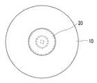
도 2는 본 발명에 따른 파라볼라 안테나의 정면도,2 is a front view of a parabola antenna according to the present invention;
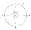
도 3은 본 발명에 따른 파라볼라 안테나의 후면도,3 is a rear view of a parabola antenna according to the present invention;
도 4는 본 발명에 따른 파라볼라 안테나의 폴라라이저를 도시한 도면,4 is a view showing a polarizer of a parabolic antenna according to the present invention;
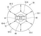
도 5는 본 발명에 따른 7 분배결합용 파라볼라안테나의 정면도,5 is a front view of the parabolic antenna 7 for distribution, according to the present invention;
도 6은 본 발명에 따른 7 분배결합용 파라볼라안테나의 측면도.Figure 6 is a side view of a seven-parabolic parabolic antenna according to the present invention.
*도면의 주요부분에 대한 부호의 설명* Explanation of symbols for main parts of the drawings
10: 주반사판20: 접시형 부반사판10: main reflector 20: dish sub-reflective plate
21: 부반사판 도체22: 부반사판 유전체21: sub-reflection plate conductor 22: sub-reflection plate dielectric
23: 유전체봉30: 유전체 피드혼 원형 도파관23: dielectric rod 30: dielectric feed horn circular waveguide
31: 원형 도파관32: 원형도파관-반사판 체결 후렌지31: circular waveguide 32: circular waveguide-reflective plate fastening flange
33: 혼복사기34: 혼복사기-원형도파관 연결구33: Mixed radiation machine 34: Mixed radiation machine-circular waveguide connector
40: 폴라라이저41: 좌회전편파 TE10모드 출력도파관 후렌지40: Polarizer 41: Left turn polarization TE10 mode output waveguide flange
42: 우회전편파 TE10모드 출력도파관 후렌지42: Right turn polarization TE10 mode output waveguide flange
43: 폴라라이저 성형 계단형 도체43: polarizer molded stepped conductor
44: 원형도파관-폴라라이저 체결 후렌지44: circular waveguide-polarizer fastening flange
본 발명은 부반사판형 파라볼라 안테나에 관한 것으로, 더욱 상세하게는 유전체 피드혼 원형 도파관을 이용하여 원편파를 방사하는 원편파 유전체 혼 파라볼라 안테나에 관한 것이다.The present invention relates to a sub-reflection plate-type parabola antenna, and more particularly, to a circularly polarized dielectric horn parabola antenna that emits circularly polarized waves using a dielectric feedhorn circular waveguide.
일반적으로, 반사경 안테나(Reflector Antenna)는 전파천문학, 초고주파통신, 위상추적 등을 목적으로 널리 사용되는 안테나로서, 반사경의 형태에 따라 평판 반사경 안테나, 코너 반사경 안테나, 전방 급전형 파라볼라 안테나, 카세그레인 안테나 등으로 구분된다.In general, a reflector antenna is an antenna widely used for radio astronomy, microwave communication, phase tracking, and the like, and includes a flat reflector antenna, a corner reflector antenna, a front feeding parabola antenna, and a casein grain antenna, depending on the shape of the reflector. Separated by.
전파망원경 등에 널리 사용되는 카세그레인(Cassegrain reflector form) 안테나는 긴 전송선이 필요한 전방급전방식의 문제점을 해결하기 위한 안테나로서, 전형적인 카세그레인 안테나는 주반사면은 포물선 형태로 하고 부반사면은 쌍곡선 형태로 만들어 급전점을 포물선의 축을 따라 정점 또는 근처에 두는 방식이다. 전형적인 카세그레인 형태의 변형으로서, 그레고리언 형태(Gregorian reflector form)의 반사경 안테나가 있다.Cassgrain reflector form antenna, widely used in radio telescopes, is an antenna to solve the problem of forward feeding method requiring long transmission line. In the vertex along or near the parabolic axis. A variation of the typical casee grain form is a reflector antenna in the Gregorian reflector form.
한편, 부반사판형 파라볼라 안테나는 통상 대형의 주반사경과 주반사경에 지지되는 소형의 부반사경, 급전 혼, 안테나 지지구조물 등으로 구성된다.On the other hand, the sub-reflection plate type parabola antenna is usually composed of a large main reflection mirror and a small sub reflection mirror, a feeding horn, an antenna support structure, and the like supported by the main reflection mirror.
그런데 종래의 부반사판형 파라볼라 안테나는 부반사판이 크고 복사기 개구가 도파관보다 넓어서 전파복사시 주반사판에서 복사하는 전력을 부반사판이 차폐하여 소형 부반사판형 파라볼라 안테나에서는 효율이 나쁘고, 부엽 복사패턴이 커서 인접 통신 서비스 지역에 간섭을 일으키는 문제점이 있다.However, the conventional sub-reflection plate parabola antenna has a larger sub-reflection plate and a wider copier opening than the waveguide, so that the sub-reflection plate shields the power radiated from the main reflection plate during radio wave radiation. There is a problem that causes interference in the adjacent communication service area.
본 발명은 상기와 같은 문제점을 해소하기 위하여 제안된 것으로, 유전체를 사용하여 유전체 혼 복사소자를 구성함으로써 복사개구가 원형도파관보다 작게 함과 아울러 부반사판도 작게 하여 차폐면적을 줄이고 부엽특성도 개선한 원편파 유전체 혼 파라볼라 안테나를 제공하는 것을 그 목적으로 한다.The present invention has been proposed to solve the above problems, by constructing a dielectric horn radiating element using a dielectric, the radiation opening is smaller than the circular waveguide, and also the sub-reflection plate is smaller to reduce the shielding area and improve the side lobe characteristics It is an object to provide a circularly polarized dielectric horn parabolic antenna.
상기와 같은 목적을 달성하기 위하여 본 발명의 안테나는, 전기도체로 된 파라볼라형 주반사판; 상기 주반사판의 중앙 전면에 부착된 원형도파관형 휘드 혼; 상기 원형도파관 휘드 혼의 개구에 유전체 봉으로 원형도파관과 연결된 접시형 부반사판; 및 상기 주반사판의 후면에 상기 원형도파관과 연결되어 송신시에는 직선편파를 원편파로 변환하고 수신시에는 원편파를 직선편파로 변환하는 폴라라이저를 구비한 것을 특징으로 한다.In order to achieve the above object, the antenna of the present invention, the parabolic main reflector plate of the electrical conductor; A circular waveguide type horn attached to the central front surface of the main reflector; A dish-shaped sub-reflection plate connected to the circular waveguide with a dielectric rod in the opening of the circular waveguide feed horn; And a polarizer connected to the circular waveguide at the rear surface of the main reflector to convert linearly polarized waves into circularly polarized waves when transmitting and converting circularly polarized waves into linearly polarized waves upon reception.
상기 주반사판은 7개의 세그먼트로 분리결합될 수 있고, 상기 휘드 혼은 원형도파관-반사판 체결 후렌지에 의해 상기 주반사판의 중앙에 고정된 원형 도파관과, 상기 원형도파관의 단부에 혼복사기-원형도파관 연결구에 의해 연결된 혼 복사기로 구성되고, 상기 혼 복사기는 원형도파관측에서 개구면으로 갈수록 점차 작아지게 되어 있다.The main reflector may be separated into seven segments, and the horn is a circular waveguide fixed to the center of the main reflector by a circular waveguide-reflector fastening flange, and a mixed-radiator-circular waveguide connector at the end of the circular waveguide. The horn copier is gradually smaller from the circular waveguide side toward the opening face.
그리고 상기 부반사판은 주반사판측이 오목한 부반사판 도체와, 상기 부반사판 도체의 오목면에 부착된 부반사판 유전체와, 상기 부반사판 유전체와 연결되고 상기 원형도파관형 휘드 혼의 개구에 삽입되어 부반사판을 지지하는 유전체 봉으로 구성되어 상기 유전체 봉의 유전율에 따라 원형도파관형 휘드 혼의 직경을 줄일 수 있다.The sub-reflection plate includes a sub-reflection plate conductor having a main reflection plate side concave, a sub-reflection plate dielectric attached to the concave surface of the sub-reflection plate conductor, and a sub-reflection plate dielectric connected to the sub-reflection plate dielectric and inserted into an opening of the circular waveguide type horn horn. It is composed of a supporting dielectric rod can reduce the diameter of the circular waveguide-shaped horn horn according to the dielectric constant of the dielectric rod.
이하, 첨부된 도면을 참조하여 본 발명의 바람직한 실시예를 자세히 설명하기로 한다.Hereinafter, exemplary embodiments of the present invention will be described in detail with reference to the accompanying drawings.
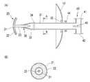
도 1의 (A)는 본 발명에 따른 파라볼라 안테나의 측면도이고 (B)는 A-A의 절개 단면도이며, 도 2는 본 발명에 따른 파라볼라 안테나의 정면도이고, 도 3은 본 발명에 따른 파라볼라 안테나의 후면도이다.Figure 1 (A) is a side view of the parabola antenna according to the invention and (B) is a cross-sectional view of the AA, Figure 2 is a front view of the parabola antenna according to the present invention, Figure 3 is a rear of the parabola antenna according to the present invention It is also.
본 발명에 따른 파라볼라 안테나는 도 1 내지 도 3에 도시된 바와 같이, 전기도체(금속)로 된 접시형 파라볼라의 주반사판(10)과, 주반사판(10)의 중앙 전면에 부착된 원형도파관형 휘드 혼(30)과, 원형도파관형 휘드 혼(30)의 개구에 유전체 봉(23)으로 원형도파관(31)과 연결된 접시형 부반사판(20)과, 주반사판(10)의 후면에 원형도파관(31)과 연결되어 송신시에는 직선편파를 원편파로 변환하고 수신시에는 원편파를 직선편파로 변환하는 폴라라이저(40)로 구성된다.Parabolic antenna according to the present invention, as shown in Figures 1 to 3, the
부반사판(20)은 주반사판측이 오목한 부반사판 도체(21)와 부반사판 도체(21)의 오목면에 부착된 부반사판 유전체(22), 부반사판 유전체(22)와 연결되고 원형도파관형 휘드 혼의 개구에 삽입되어 부반사판(20)을 지지하는 유전체 봉(23)으로 구성된다. 이때, 유전체 봉(23)의 유전율에 따라 원형도파관형 휘드 혼의 직경을 줄일 수 있다.The
원형도파관형 피드 혼(30)은 원형도파관-반사판 체결 후렌지(32)에 의해 주반사판(10)의 중앙에 고정된 원형 도파관(31)과, 원형도파관(31)의 단부에 혼복사기-원형도파관 연결구(34)에 의해 연결된 혼 복사기(33)로 구성된다. 본 발명에 따른 원도파관형 피드혼의 혼 복사기(33)는 원형도파관측에서 개구면으로 갈수록 점차 작아지게 되어 있고, 혼복사기-원형도파관 연결구(34)에 의해 원형도파관(31)과 분리 가능하게 됨으로써 정합조정이 용이하도록 되어 있다.The circular
폴라라이저(40)는 도 1 및 도 4에 도시된 바와 같이, 원형도파관-폴라라이저 체결 후렌지(43)에 의해 주반사판(10)에 고정된 원형도파관(31)과 연결되고, 원형도파관(31)과 연결되는 부분은 원형이나 점차 정사각형으로 변형 후 내부에 삽입된 계단형 금속편(44)에 의해 원형도파관측의 원편파를 직선편파로 분리하여 좌회전편파- TE10모드 출력도파관 후렌지(41)와 우회전편파- TE10모드 출력도파관 후렌지(42)로 출력한다.1 and 4, the
이와 같이 구성된 본 발명에 따른 원편파 유전체 혼 파라볼라 안테나는 송신 시 좌회전편파- TE10모드 출력도파관 후렌지(41)나 우회전편파- TE10모드 출력도파관 후렌지(42)로부터 직선편파를 입력받아 폴라라이저에서 원편파로 변환한 후 원형도파관을 통해 휘드혼 복사기에서 부반사판을 향해 전방으로 복사하고, 부반사판은 원편파를 다시 주반사판으로 반사하여 주반사판이 원편파를 공기중으로 송출한다.The circularly polarized dielectric horn parabola antenna according to the present invention configured as described above receives a linearly polarized wave from a left polarized polarization-TE10 mode output waveguide Hurenji 41 or a right rotating polarization-TE10 mode output waveguide Hunge 42 and transmits a circular polarization in the polarizer. After converting to, through the circular waveguide, the front horn copier radiates forward toward the sub-reflection plate, and the sub-reflection plate reflects the circular polarization back to the main reflection plate, and the main reflection plate sends out the circular polarization to the air.
반대로 수신시에는 주반사판이 공기중으로부터 수신한 원편파를 부반사판측으로 집중시키고, 분반사판은 이를 휘드혼 복사기로 전달하여와 원형도파관을 통해 폴라이이저로 전달된다. 폴라라이저는 원형도파관으로부터 전달된 원편파를 계단형 금속편에 의해 직선편파로 분리하여 좌회전편파- TE10모드 출력도파관 후렌지(41)와 우회전편파- TE10모드 출력도파관 후렌지(42)로 출력한다.On the contrary, upon reception, the main reflection plate concentrates the circularly polarized wave received from the air toward the sub-reflection plate side, and the diffuse reflection plate is transmitted to the whid horn copier and transmitted to the polarizer through the circular waveguide. The polarizer separates the circularly polarized wave transmitted from the circular waveguide into a linearly polarized wave by a stepped metal piece and outputs it to the left rotating polarized wave-TE10 mode output waveguide Huren 41 and the right rotating polarized wave-TE10 mode output waveguide Huren 42.
도 5는 본 발명에 따른 7 분배결합용 파라볼라 안테나의 정면도이고, 도 6은 본 발명에 따른 7 분배결합용 파라볼라안테나의 측면도이다.Figure 5 is a front view of the seven distribution parabolic antenna according to the present invention, Figure 6 is a side view of the seven distribution parabolic antenna according to the present invention.
본 발명에 따른 7 분배결합용 파라볼라 안테나는 주반사판이 도 5 및 도 6에 도시된 바와 같이, 원주면을 따라 균등하게 6등분된 원주형 반사판 세그먼트와, 중앙부의 정육각형 반사판 세그먼트로 구성되어 있다. 이와 같은 반사판 세그먼트들은 체결구에 의해 체결되어 주반사판을 형성하고, 중앙의 반사판 세그먼트에는 원형도파관형 유전체 피드혼이 부착되어 있다.The parabolic antenna 7 for distribution according to the present invention comprises a cylindrical reflector segment equally divided into six equally along the circumferential surface and a regular hexagonal reflector segment in the center, as shown in FIGS. 5 and 6. These reflector plate segments are fastened by fasteners to form a main reflector, and a circular waveguide dielectric feed horn is attached to the central reflector segment.
이와 같은 본 발명의 다른 실시예는 주반사판이 7개의 세그먼트로 조립된 것을 제외하고는 나머지 구성은 앞서 설명한 실시예와 동일하므로 더이상의 설명은 생략하기로 한다.The other embodiment of the present invention is the same as the above-described embodiment except that the main reflector is assembled into seven segments, further description will be omitted.
이상에서 설명한 바와 같이, 본 발명에 따르면 유전체 봉을 통해 부반사판을 원형도파관에 체결함과 아울러 유전체봉의 유전율에 의해 휘드 혼의 직경을 작게 함으로써 부반사판에 의한 차폐를 줄일 수 있고, 부엽 복사패턴도 개선하여 인접 통신 서비스 지역에 간섭을 줄일 수 있는 효과가 있다.As described above, according to the present invention, the sub-reflection plate is fastened to the circular waveguide through the dielectric rod, and the shielding of the sub-reflection plate can be reduced by reducing the diameter of the bead horn by the dielectric constant of the dielectric rod, and the sub-lobe radiation pattern is also improved. Therefore, there is an effect of reducing interference in the adjacent communication service area.
Claims (4)
Translated fromKoreanPriority Applications (1)
| Application Number | Priority Date | Filing Date | Title |
|---|---|---|---|
| KR1020060094376AKR100849702B1 (en) | 2006-09-27 | 2006-09-27 | Circular Wave Dielectric Horn Parabolar Antenna |
Applications Claiming Priority (1)
| Application Number | Priority Date | Filing Date | Title |
|---|---|---|---|
| KR1020060094376AKR100849702B1 (en) | 2006-09-27 | 2006-09-27 | Circular Wave Dielectric Horn Parabolar Antenna |
Publications (2)
| Publication Number | Publication Date |
|---|---|
| KR20080028714Atrue KR20080028714A (en) | 2008-04-01 |
| KR100849702B1 KR100849702B1 (en) | 2008-08-01 |
Family
ID=39531599
Family Applications (1)
| Application Number | Title | Priority Date | Filing Date |
|---|---|---|---|
| KR1020060094376AExpired - Fee RelatedKR100849702B1 (en) | 2006-09-27 | 2006-09-27 | Circular Wave Dielectric Horn Parabolar Antenna |
Country Status (1)
| Country | Link |
|---|---|
| KR (1) | KR100849702B1 (en) |
Cited By (2)
| Publication number | Priority date | Publication date | Assignee | Title |
|---|---|---|---|---|
| KR101105608B1 (en)* | 2009-12-28 | 2012-01-18 | (주)하이게인안테나 | Monopule tracking radar antenna |
| US10879619B2 (en) | 2009-06-04 | 2020-12-29 | Ubiquiti Inc. | Microwave system |
Families Citing this family (140)
| Publication number | Priority date | Publication date | Assignee | Title |
|---|---|---|---|---|
| US10009065B2 (en) | 2012-12-05 | 2018-06-26 | At&T Intellectual Property I, L.P. | Backhaul link for distributed antenna system |
| US9113347B2 (en) | 2012-12-05 | 2015-08-18 | At&T Intellectual Property I, Lp | Backhaul link for distributed antenna system |
| CN103247865B (en)* | 2012-12-12 | 2015-09-16 | 上海航天测控通信研究所 | A kind of X-band wide beam circular polarized antenna for lunar surface rover |
| US9999038B2 (en) | 2013-05-31 | 2018-06-12 | At&T Intellectual Property I, L.P. | Remote distributed antenna system |
| US9525524B2 (en) | 2013-05-31 | 2016-12-20 | At&T Intellectual Property I, L.P. | Remote distributed antenna system |
| US8897697B1 (en) | 2013-11-06 | 2014-11-25 | At&T Intellectual Property I, Lp | Millimeter-wave surface-wave communications |
| US9692101B2 (en) | 2014-08-26 | 2017-06-27 | At&T Intellectual Property I, L.P. | Guided wave couplers for coupling electromagnetic waves between a waveguide surface and a surface of a wire |
| US9768833B2 (en) | 2014-09-15 | 2017-09-19 | At&T Intellectual Property I, L.P. | Method and apparatus for sensing a condition in a transmission medium of electromagnetic waves |
| US10063280B2 (en) | 2014-09-17 | 2018-08-28 | At&T Intellectual Property I, L.P. | Monitoring and mitigating conditions in a communication network |
| US9615269B2 (en) | 2014-10-02 | 2017-04-04 | At&T Intellectual Property I, L.P. | Method and apparatus that provides fault tolerance in a communication network |
| US9685992B2 (en) | 2014-10-03 | 2017-06-20 | At&T Intellectual Property I, L.P. | Circuit panel network and methods thereof |
| US9503189B2 (en) | 2014-10-10 | 2016-11-22 | At&T Intellectual Property I, L.P. | Method and apparatus for arranging communication sessions in a communication system |
| US9762289B2 (en) | 2014-10-14 | 2017-09-12 | At&T Intellectual Property I, L.P. | Method and apparatus for transmitting or receiving signals in a transportation system |
| US9973299B2 (en) | 2014-10-14 | 2018-05-15 | At&T Intellectual Property I, L.P. | Method and apparatus for adjusting a mode of communication in a communication network |
| US9780834B2 (en) | 2014-10-21 | 2017-10-03 | At&T Intellectual Property I, L.P. | Method and apparatus for transmitting electromagnetic waves |
| US9312919B1 (en) | 2014-10-21 | 2016-04-12 | At&T Intellectual Property I, Lp | Transmission device with impairment compensation and methods for use therewith |
| US9627768B2 (en) | 2014-10-21 | 2017-04-18 | At&T Intellectual Property I, L.P. | Guided-wave transmission device with non-fundamental mode propagation and methods for use therewith |
| US9577306B2 (en) | 2014-10-21 | 2017-02-21 | At&T Intellectual Property I, L.P. | Guided-wave transmission device and methods for use therewith |
| US9769020B2 (en) | 2014-10-21 | 2017-09-19 | At&T Intellectual Property I, L.P. | Method and apparatus for responding to events affecting communications in a communication network |
| US9653770B2 (en) | 2014-10-21 | 2017-05-16 | At&T Intellectual Property I, L.P. | Guided wave coupler, coupling module and methods for use therewith |
| US9520945B2 (en) | 2014-10-21 | 2016-12-13 | At&T Intellectual Property I, L.P. | Apparatus for providing communication services and methods thereof |
| US9544006B2 (en) | 2014-11-20 | 2017-01-10 | At&T Intellectual Property I, L.P. | Transmission device with mode division multiplexing and methods for use therewith |
| US10009067B2 (en) | 2014-12-04 | 2018-06-26 | At&T Intellectual Property I, L.P. | Method and apparatus for configuring a communication interface |
| US9997819B2 (en) | 2015-06-09 | 2018-06-12 | At&T Intellectual Property I, L.P. | Transmission medium and method for facilitating propagation of electromagnetic waves via a core |
| US9800327B2 (en) | 2014-11-20 | 2017-10-24 | At&T Intellectual Property I, L.P. | Apparatus for controlling operations of a communication device and methods thereof |
| US9742462B2 (en) | 2014-12-04 | 2017-08-22 | At&T Intellectual Property I, L.P. | Transmission medium and communication interfaces and methods for use therewith |
| US9461706B1 (en) | 2015-07-31 | 2016-10-04 | At&T Intellectual Property I, Lp | Method and apparatus for exchanging communication signals |
| US9954287B2 (en) | 2014-11-20 | 2018-04-24 | At&T Intellectual Property I, L.P. | Apparatus for converting wireless signals and electromagnetic waves and methods thereof |
| US10243784B2 (en) | 2014-11-20 | 2019-03-26 | At&T Intellectual Property I, L.P. | System for generating topology information and methods thereof |
| US10144036B2 (en) | 2015-01-30 | 2018-12-04 | At&T Intellectual Property I, L.P. | Method and apparatus for mitigating interference affecting a propagation of electromagnetic waves guided by a transmission medium |
| US9876570B2 (en) | 2015-02-20 | 2018-01-23 | At&T Intellectual Property I, Lp | Guided-wave transmission device with non-fundamental mode propagation and methods for use therewith |
| US9749013B2 (en) | 2015-03-17 | 2017-08-29 | At&T Intellectual Property I, L.P. | Method and apparatus for reducing attenuation of electromagnetic waves guided by a transmission medium |
| US9705561B2 (en) | 2015-04-24 | 2017-07-11 | At&T Intellectual Property I, L.P. | Directional coupling device and methods for use therewith |
| US10224981B2 (en) | 2015-04-24 | 2019-03-05 | At&T Intellectual Property I, Lp | Passive electrical coupling device and methods for use therewith |
| US9793954B2 (en) | 2015-04-28 | 2017-10-17 | At&T Intellectual Property I, L.P. | Magnetic coupling device and methods for use therewith |
| US9490869B1 (en) | 2015-05-14 | 2016-11-08 | At&T Intellectual Property I, L.P. | Transmission medium having multiple cores and methods for use therewith |
| US9871282B2 (en) | 2015-05-14 | 2018-01-16 | At&T Intellectual Property I, L.P. | At least one transmission medium having a dielectric surface that is covered at least in part by a second dielectric |
| US10650940B2 (en) | 2015-05-15 | 2020-05-12 | At&T Intellectual Property I, L.P. | Transmission medium having a conductive material and methods for use therewith |
| US9917341B2 (en) | 2015-05-27 | 2018-03-13 | At&T Intellectual Property I, L.P. | Apparatus and method for launching electromagnetic waves and for modifying radial dimensions of the propagating electromagnetic waves |
| US10103801B2 (en) | 2015-06-03 | 2018-10-16 | At&T Intellectual Property I, L.P. | Host node device and methods for use therewith |
| US9912381B2 (en) | 2015-06-03 | 2018-03-06 | At&T Intellectual Property I, Lp | Network termination and methods for use therewith |
| US10812174B2 (en) | 2015-06-03 | 2020-10-20 | At&T Intellectual Property I, L.P. | Client node device and methods for use therewith |
| US9866309B2 (en) | 2015-06-03 | 2018-01-09 | At&T Intellectual Property I, Lp | Host node device and methods for use therewith |
| US9913139B2 (en) | 2015-06-09 | 2018-03-06 | At&T Intellectual Property I, L.P. | Signal fingerprinting for authentication of communicating devices |
| US10142086B2 (en) | 2015-06-11 | 2018-11-27 | At&T Intellectual Property I, L.P. | Repeater and methods for use therewith |
| US9608692B2 (en) | 2015-06-11 | 2017-03-28 | At&T Intellectual Property I, L.P. | Repeater and methods for use therewith |
| US9820146B2 (en) | 2015-06-12 | 2017-11-14 | At&T Intellectual Property I, L.P. | Method and apparatus for authentication and identity management of communicating devices |
| US9667317B2 (en) | 2015-06-15 | 2017-05-30 | At&T Intellectual Property I, L.P. | Method and apparatus for providing security using network traffic adjustments |
| US9640850B2 (en) | 2015-06-25 | 2017-05-02 | At&T Intellectual Property I, L.P. | Methods and apparatus for inducing a non-fundamental wave mode on a transmission medium |
| US9865911B2 (en) | 2015-06-25 | 2018-01-09 | At&T Intellectual Property I, L.P. | Waveguide system for slot radiating first electromagnetic waves that are combined into a non-fundamental wave mode second electromagnetic wave on a transmission medium |
| US9509415B1 (en) | 2015-06-25 | 2016-11-29 | At&T Intellectual Property I, L.P. | Methods and apparatus for inducing a fundamental wave mode on a transmission medium |
| US10033108B2 (en) | 2015-07-14 | 2018-07-24 | At&T Intellectual Property I, L.P. | Apparatus and methods for generating an electromagnetic wave having a wave mode that mitigates interference |
| US10170840B2 (en) | 2015-07-14 | 2019-01-01 | At&T Intellectual Property I, L.P. | Apparatus and methods for sending or receiving electromagnetic signals |
| US10205655B2 (en) | 2015-07-14 | 2019-02-12 | At&T Intellectual Property I, L.P. | Apparatus and methods for communicating utilizing an antenna array and multiple communication paths |
| US10148016B2 (en) | 2015-07-14 | 2018-12-04 | At&T Intellectual Property I, L.P. | Apparatus and methods for communicating utilizing an antenna array |
| US9722318B2 (en) | 2015-07-14 | 2017-08-01 | At&T Intellectual Property I, L.P. | Method and apparatus for coupling an antenna to a device |
| US10341142B2 (en) | 2015-07-14 | 2019-07-02 | At&T Intellectual Property I, L.P. | Apparatus and methods for generating non-interfering electromagnetic waves on an uninsulated conductor |
| US10320586B2 (en) | 2015-07-14 | 2019-06-11 | At&T Intellectual Property I, L.P. | Apparatus and methods for generating non-interfering electromagnetic waves on an insulated transmission medium |
| US9628116B2 (en) | 2015-07-14 | 2017-04-18 | At&T Intellectual Property I, L.P. | Apparatus and methods for transmitting wireless signals |
| US10044409B2 (en) | 2015-07-14 | 2018-08-07 | At&T Intellectual Property I, L.P. | Transmission medium and methods for use therewith |
| US10033107B2 (en) | 2015-07-14 | 2018-07-24 | At&T Intellectual Property I, L.P. | Method and apparatus for coupling an antenna to a device |
| US9847566B2 (en) | 2015-07-14 | 2017-12-19 | At&T Intellectual Property I, L.P. | Method and apparatus for adjusting a field of a signal to mitigate interference |
| US9882257B2 (en) | 2015-07-14 | 2018-01-30 | At&T Intellectual Property I, L.P. | Method and apparatus for launching a wave mode that mitigates interference |
| US9853342B2 (en) | 2015-07-14 | 2017-12-26 | At&T Intellectual Property I, L.P. | Dielectric transmission medium connector and methods for use therewith |
| US10090606B2 (en) | 2015-07-15 | 2018-10-02 | At&T Intellectual Property I, L.P. | Antenna system with dielectric array and methods for use therewith |
| US9793951B2 (en) | 2015-07-15 | 2017-10-17 | At&T Intellectual Property I, L.P. | Method and apparatus for launching a wave mode that mitigates interference |
| US9608740B2 (en) | 2015-07-15 | 2017-03-28 | At&T Intellectual Property I, L.P. | Method and apparatus for launching a wave mode that mitigates interference |
| US9948333B2 (en) | 2015-07-23 | 2018-04-17 | At&T Intellectual Property I, L.P. | Method and apparatus for wireless communications to mitigate interference |
| US9912027B2 (en) | 2015-07-23 | 2018-03-06 | At&T Intellectual Property I, L.P. | Method and apparatus for exchanging communication signals |
| US9749053B2 (en) | 2015-07-23 | 2017-08-29 | At&T Intellectual Property I, L.P. | Node device, repeater and methods for use therewith |
| US9871283B2 (en) | 2015-07-23 | 2018-01-16 | At&T Intellectual Property I, Lp | Transmission medium having a dielectric core comprised of plural members connected by a ball and socket configuration |
| US9967173B2 (en) | 2015-07-31 | 2018-05-08 | At&T Intellectual Property I, L.P. | Method and apparatus for authentication and identity management of communicating devices |
| US9735833B2 (en) | 2015-07-31 | 2017-08-15 | At&T Intellectual Property I, L.P. | Method and apparatus for communications management in a neighborhood network |
| US9904535B2 (en) | 2015-09-14 | 2018-02-27 | At&T Intellectual Property I, L.P. | Method and apparatus for distributing software |
| US10079661B2 (en) | 2015-09-16 | 2018-09-18 | At&T Intellectual Property I, L.P. | Method and apparatus for use with a radio distributed antenna system having a clock reference |
| US10136434B2 (en) | 2015-09-16 | 2018-11-20 | At&T Intellectual Property I, L.P. | Method and apparatus for use with a radio distributed antenna system having an ultra-wideband control channel |
| US10009063B2 (en) | 2015-09-16 | 2018-06-26 | At&T Intellectual Property I, L.P. | Method and apparatus for use with a radio distributed antenna system having an out-of-band reference signal |
| US9769128B2 (en) | 2015-09-28 | 2017-09-19 | At&T Intellectual Property I, L.P. | Method and apparatus for encryption of communications over a network |
| US9729197B2 (en) | 2015-10-01 | 2017-08-08 | At&T Intellectual Property I, L.P. | Method and apparatus for communicating network management traffic over a network |
| US9876264B2 (en) | 2015-10-02 | 2018-01-23 | At&T Intellectual Property I, Lp | Communication system, guided wave switch and methods for use therewith |
| US10665942B2 (en) | 2015-10-16 | 2020-05-26 | At&T Intellectual Property I, L.P. | Method and apparatus for adjusting wireless communications |
| US10355367B2 (en) | 2015-10-16 | 2019-07-16 | At&T Intellectual Property I, L.P. | Antenna structure for exchanging wireless signals |
| US9912419B1 (en) | 2016-08-24 | 2018-03-06 | At&T Intellectual Property I, L.P. | Method and apparatus for managing a fault in a distributed antenna system |
| US9860075B1 (en) | 2016-08-26 | 2018-01-02 | At&T Intellectual Property I, L.P. | Method and communication node for broadband distribution |
| US10291311B2 (en) | 2016-09-09 | 2019-05-14 | At&T Intellectual Property I, L.P. | Method and apparatus for mitigating a fault in a distributed antenna system |
| US11032819B2 (en) | 2016-09-15 | 2021-06-08 | At&T Intellectual Property I, L.P. | Method and apparatus for use with a radio distributed antenna system having a control channel reference signal |
| US10135146B2 (en) | 2016-10-18 | 2018-11-20 | At&T Intellectual Property I, L.P. | Apparatus and methods for launching guided waves via circuits |
| US10135147B2 (en) | 2016-10-18 | 2018-11-20 | At&T Intellectual Property I, L.P. | Apparatus and methods for launching guided waves via an antenna |
| US10340600B2 (en) | 2016-10-18 | 2019-07-02 | At&T Intellectual Property I, L.P. | Apparatus and methods for launching guided waves via plural waveguide systems |
| US9876605B1 (en) | 2016-10-21 | 2018-01-23 | At&T Intellectual Property I, L.P. | Launcher and coupling system to support desired guided wave mode |
| US10811767B2 (en) | 2016-10-21 | 2020-10-20 | At&T Intellectual Property I, L.P. | System and dielectric antenna with convex dielectric radome |
| US10374316B2 (en) | 2016-10-21 | 2019-08-06 | At&T Intellectual Property I, L.P. | System and dielectric antenna with non-uniform dielectric |
| US10312567B2 (en) | 2016-10-26 | 2019-06-04 | At&T Intellectual Property I, L.P. | Launcher with planar strip antenna and methods for use therewith |
| US10498044B2 (en) | 2016-11-03 | 2019-12-03 | At&T Intellectual Property I, L.P. | Apparatus for configuring a surface of an antenna |
| US10225025B2 (en) | 2016-11-03 | 2019-03-05 | At&T Intellectual Property I, L.P. | Method and apparatus for detecting a fault in a communication system |
| US10291334B2 (en) | 2016-11-03 | 2019-05-14 | At&T Intellectual Property I, L.P. | System for detecting a fault in a communication system |
| US10224634B2 (en) | 2016-11-03 | 2019-03-05 | At&T Intellectual Property I, L.P. | Methods and apparatus for adjusting an operational characteristic of an antenna |
| US10535928B2 (en) | 2016-11-23 | 2020-01-14 | At&T Intellectual Property I, L.P. | Antenna system and methods for use therewith |
| US10340603B2 (en) | 2016-11-23 | 2019-07-02 | At&T Intellectual Property I, L.P. | Antenna system having shielded structural configurations for assembly |
| US10340601B2 (en) | 2016-11-23 | 2019-07-02 | At&T Intellectual Property I, L.P. | Multi-antenna system and methods for use therewith |
| US10178445B2 (en) | 2016-11-23 | 2019-01-08 | At&T Intellectual Property I, L.P. | Methods, devices, and systems for load balancing between a plurality of waveguides |
| US10090594B2 (en) | 2016-11-23 | 2018-10-02 | At&T Intellectual Property I, L.P. | Antenna system having structural configurations for assembly |
| US10305190B2 (en) | 2016-12-01 | 2019-05-28 | At&T Intellectual Property I, L.P. | Reflecting dielectric antenna system and methods for use therewith |
| US10361489B2 (en) | 2016-12-01 | 2019-07-23 | At&T Intellectual Property I, L.P. | Dielectric dish antenna system and methods for use therewith |
| US10755542B2 (en) | 2016-12-06 | 2020-08-25 | At&T Intellectual Property I, L.P. | Method and apparatus for surveillance via guided wave communication |
| US10135145B2 (en) | 2016-12-06 | 2018-11-20 | At&T Intellectual Property I, L.P. | Apparatus and methods for generating an electromagnetic wave along a transmission medium |
| US10637149B2 (en) | 2016-12-06 | 2020-04-28 | At&T Intellectual Property I, L.P. | Injection molded dielectric antenna and methods for use therewith |
| US10819035B2 (en) | 2016-12-06 | 2020-10-27 | At&T Intellectual Property I, L.P. | Launcher with helical antenna and methods for use therewith |
| US10727599B2 (en) | 2016-12-06 | 2020-07-28 | At&T Intellectual Property I, L.P. | Launcher with slot antenna and methods for use therewith |
| US10439675B2 (en) | 2016-12-06 | 2019-10-08 | At&T Intellectual Property I, L.P. | Method and apparatus for repeating guided wave communication signals |
| US10694379B2 (en) | 2016-12-06 | 2020-06-23 | At&T Intellectual Property I, L.P. | Waveguide system with device-based authentication and methods for use therewith |
| US10326494B2 (en) | 2016-12-06 | 2019-06-18 | At&T Intellectual Property I, L.P. | Apparatus for measurement de-embedding and methods for use therewith |
| US10382976B2 (en) | 2016-12-06 | 2019-08-13 | At&T Intellectual Property I, L.P. | Method and apparatus for managing wireless communications based on communication paths and network device positions |
| US9927517B1 (en) | 2016-12-06 | 2018-03-27 | At&T Intellectual Property I, L.P. | Apparatus and methods for sensing rainfall |
| US10020844B2 (en) | 2016-12-06 | 2018-07-10 | T&T Intellectual Property I, L.P. | Method and apparatus for broadcast communication via guided waves |
| US10389029B2 (en) | 2016-12-07 | 2019-08-20 | At&T Intellectual Property I, L.P. | Multi-feed dielectric antenna system with core selection and methods for use therewith |
| US10446936B2 (en) | 2016-12-07 | 2019-10-15 | At&T Intellectual Property I, L.P. | Multi-feed dielectric antenna system and methods for use therewith |
| US10139820B2 (en) | 2016-12-07 | 2018-11-27 | At&T Intellectual Property I, L.P. | Method and apparatus for deploying equipment of a communication system |
| US9893795B1 (en) | 2016-12-07 | 2018-02-13 | At&T Intellectual Property I, Lp | Method and repeater for broadband distribution |
| US10027397B2 (en) | 2016-12-07 | 2018-07-17 | At&T Intellectual Property I, L.P. | Distributed antenna system and methods for use therewith |
| US10168695B2 (en) | 2016-12-07 | 2019-01-01 | At&T Intellectual Property I, L.P. | Method and apparatus for controlling an unmanned aircraft |
| US10359749B2 (en) | 2016-12-07 | 2019-07-23 | At&T Intellectual Property I, L.P. | Method and apparatus for utilities management via guided wave communication |
| US10243270B2 (en) | 2016-12-07 | 2019-03-26 | At&T Intellectual Property I, L.P. | Beam adaptive multi-feed dielectric antenna system and methods for use therewith |
| US10938108B2 (en) | 2016-12-08 | 2021-03-02 | At&T Intellectual Property I, L.P. | Frequency selective multi-feed dielectric antenna system and methods for use therewith |
| US9998870B1 (en) | 2016-12-08 | 2018-06-12 | At&T Intellectual Property I, L.P. | Method and apparatus for proximity sensing |
| US9911020B1 (en) | 2016-12-08 | 2018-03-06 | At&T Intellectual Property I, L.P. | Method and apparatus for tracking via a radio frequency identification device |
| US10916969B2 (en) | 2016-12-08 | 2021-02-09 | At&T Intellectual Property I, L.P. | Method and apparatus for providing power using an inductive coupling |
| US10069535B2 (en) | 2016-12-08 | 2018-09-04 | At&T Intellectual Property I, L.P. | Apparatus and methods for launching electromagnetic waves having a certain electric field structure |
| US10530505B2 (en) | 2016-12-08 | 2020-01-07 | At&T Intellectual Property I, L.P. | Apparatus and methods for launching electromagnetic waves along a transmission medium |
| US10411356B2 (en) | 2016-12-08 | 2019-09-10 | At&T Intellectual Property I, L.P. | Apparatus and methods for selectively targeting communication devices with an antenna array |
| US10326689B2 (en) | 2016-12-08 | 2019-06-18 | At&T Intellectual Property I, L.P. | Method and system for providing alternative communication paths |
| US10389037B2 (en) | 2016-12-08 | 2019-08-20 | At&T Intellectual Property I, L.P. | Apparatus and methods for selecting sections of an antenna array and use therewith |
| US10601494B2 (en) | 2016-12-08 | 2020-03-24 | At&T Intellectual Property I, L.P. | Dual-band communication device and method for use therewith |
| US10103422B2 (en) | 2016-12-08 | 2018-10-16 | At&T Intellectual Property I, L.P. | Method and apparatus for mounting network devices |
| US10777873B2 (en) | 2016-12-08 | 2020-09-15 | At&T Intellectual Property I, L.P. | Method and apparatus for mounting network devices |
| US10264586B2 (en) | 2016-12-09 | 2019-04-16 | At&T Mobility Ii Llc | Cloud-based packet controller and methods for use therewith |
| US10340983B2 (en) | 2016-12-09 | 2019-07-02 | At&T Intellectual Property I, L.P. | Method and apparatus for surveying remote sites via guided wave communications |
| US9838896B1 (en) | 2016-12-09 | 2017-12-05 | At&T Intellectual Property I, L.P. | Method and apparatus for assessing network coverage |
| US9973940B1 (en) | 2017-02-27 | 2018-05-15 | At&T Intellectual Property I, L.P. | Apparatus and methods for dynamic impedance matching of a guided wave launcher |
| US10298293B2 (en) | 2017-03-13 | 2019-05-21 | At&T Intellectual Property I, L.P. | Apparatus of communication utilizing wireless network devices |
Family Cites Families (2)
| Publication number | Priority date | Publication date | Assignee | Title |
|---|---|---|---|---|
| US3983560A (en) | 1974-06-06 | 1976-09-28 | Andrew Corporation | Cassegrain antenna with improved subreflector for terrestrial communication systems |
| JP3350373B2 (en) | 1996-06-10 | 2002-11-25 | 久松 中野 | Double reflector type small-diameter parabolic antenna device |
- 2006
- 2006-09-27KRKR1020060094376Apatent/KR100849702B1/ennot_activeExpired - Fee Related
Cited By (2)
| Publication number | Priority date | Publication date | Assignee | Title |
|---|---|---|---|---|
| US10879619B2 (en) | 2009-06-04 | 2020-12-29 | Ubiquiti Inc. | Microwave system |
| KR101105608B1 (en)* | 2009-12-28 | 2012-01-18 | (주)하이게인안테나 | Monopule tracking radar antenna |
Also Published As
| Publication number | Publication date |
|---|---|
| KR100849702B1 (en) | 2008-08-01 |
Similar Documents
| Publication | Publication Date | Title |
|---|---|---|
| KR100849702B1 (en) | Circular Wave Dielectric Horn Parabolar Antenna | |
| US10224638B2 (en) | Lens antenna | |
| EP0859427B1 (en) | Dual-reflector microwave antenna | |
| US7075492B1 (en) | High performance reflector antenna system and feed structure | |
| US6861998B2 (en) | Transmission/reception sources of electromagnetic waves for multireflector antenna | |
| US6919855B2 (en) | Tuned perturbation cone feed for reflector antenna | |
| US6724349B1 (en) | Splashplate antenna system with improved waveguide and splashplate (sub-reflector) designs | |
| US7167138B2 (en) | Triple-band offset hybrid antenna using shaped reflector | |
| CN104025383A (en) | Reflector antenna including dual band splashplate support | |
| WO2023000957A1 (en) | Antenna array, system, and millimeter wave radar | |
| AU2008332129A1 (en) | Axially displaced ellipse antenna system using helix feed for dual polarization | |
| JP3813581B2 (en) | Antenna device | |
| KR20110006953A (en) | Reverse center feed helix feed broadband antenna | |
| US20150288068A1 (en) | Primary radiator | |
| CN106654540B (en) | Antenna element assembly and spotlight antenna | |
| CA1302559C (en) | High performance dipole feed for reflector antennas | |
| US7280081B2 (en) | Parabolic reflector and antenna incorporating same | |
| KR101032190B1 (en) | Dielectric Load Horn and Dual Reflector Antenna Using the Same | |
| CN109687092B (en) | Low-profile omnidirectional circularly polarized antenna | |
| US2644092A (en) | Antenna | |
| US4516129A (en) | Waveguide with dielectric coated flange antenna feed | |
| CN222915152U (en) | Antenna structure | |
| CN217881888U (en) | Flat antenna and phased array antenna array | |
| KR102023959B1 (en) | Parabolic antenna | |
| US7142172B2 (en) | Antenna reflection structure |
Legal Events
| Date | Code | Title | Description |
|---|---|---|---|
| A201 | Request for examination | ||
| PA0109 | Patent application | St.27 status event code:A-0-1-A10-A12-nap-PA0109 | |
| PA0201 | Request for examination | St.27 status event code:A-1-2-D10-D11-exm-PA0201 | |
| R18-X000 | Changes to party contact information recorded | St.27 status event code:A-3-3-R10-R18-oth-X000 | |
| R18-X000 | Changes to party contact information recorded | St.27 status event code:A-3-3-R10-R18-oth-X000 | |
| D13-X000 | Search requested | St.27 status event code:A-1-2-D10-D13-srh-X000 | |
| D14-X000 | Search report completed | St.27 status event code:A-1-2-D10-D14-srh-X000 | |
| E902 | Notification of reason for refusal | ||
| PE0902 | Notice of grounds for rejection | St.27 status event code:A-1-2-D10-D21-exm-PE0902 | |
| P11-X000 | Amendment of application requested | St.27 status event code:A-2-2-P10-P11-nap-X000 | |
| P13-X000 | Application amended | St.27 status event code:A-2-2-P10-P13-nap-X000 | |
| PG1501 | Laying open of application | St.27 status event code:A-1-1-Q10-Q12-nap-PG1501 | |
| E701 | Decision to grant or registration of patent right | ||
| PE0701 | Decision of registration | St.27 status event code:A-1-2-D10-D22-exm-PE0701 | |
| GRNT | Written decision to grant | ||
| PR0701 | Registration of establishment | St.27 status event code:A-2-4-F10-F11-exm-PR0701 | |
| PR1002 | Payment of registration fee | St.27 status event code:A-2-2-U10-U11-oth-PR1002 Fee payment year number:1 | |
| PG1601 | Publication of registration | St.27 status event code:A-4-4-Q10-Q13-nap-PG1601 | |
| PR1001 | Payment of annual fee | St.27 status event code:A-4-4-U10-U11-oth-PR1001 Fee payment year number:4 | |
| FPAY | Annual fee payment | Payment date:20120514 Year of fee payment:5 | |
| PR1001 | Payment of annual fee | St.27 status event code:A-4-4-U10-U11-oth-PR1001 Fee payment year number:5 | |
| FPAY | Annual fee payment | Payment date:20130826 Year of fee payment:6 | |
| PR1001 | Payment of annual fee | St.27 status event code:A-4-4-U10-U11-oth-PR1001 Fee payment year number:6 | |
| PR1001 | Payment of annual fee | St.27 status event code:A-4-4-U10-U11-oth-PR1001 Fee payment year number:7 | |
| FPAY | Annual fee payment | Payment date:20150622 Year of fee payment:8 | |
| PR1001 | Payment of annual fee | St.27 status event code:A-4-4-U10-U11-oth-PR1001 Fee payment year number:8 | |
| FPAY | Annual fee payment | Payment date:20161221 Year of fee payment:9 | |
| PR1001 | Payment of annual fee | St.27 status event code:A-4-4-U10-U11-oth-PR1001 Fee payment year number:9 | |
| P22-X000 | Classification modified | St.27 status event code:A-4-4-P10-P22-nap-X000 | |
| PC1903 | Unpaid annual fee | St.27 status event code:A-4-4-U10-U13-oth-PC1903 Not in force date:20170726 Payment event data comment text:Termination Category : DEFAULT_OF_REGISTRATION_FEE | |
| K11-X000 | Ip right revival requested | St.27 status event code:A-6-4-K10-K11-oth-X000 | |
| PC1903 | Unpaid annual fee | St.27 status event code:N-4-6-H10-H13-oth-PC1903 Ip right cessation event data comment text:Termination Category : DEFAULT_OF_REGISTRATION_FEE Not in force date:20170726 | |
| PR0401 | Registration of restoration | St.27 status event code:A-6-4-K10-K13-oth-PR0401 | |
| PR1001 | Payment of annual fee | St.27 status event code:A-4-4-U10-U11-oth-PR1001 Fee payment year number:10 | |
| FPAY | Annual fee payment | Payment date:20180927 Year of fee payment:11 | |
| PR1001 | Payment of annual fee | St.27 status event code:A-4-4-U10-U11-oth-PR1001 Fee payment year number:11 | |
| S14-X000 | Exclusive voluntary license recorded | St.27 status event code:A-4-4-S10-S14-lic-X000 | |
| FPAY | Annual fee payment | Payment date:20190723 Year of fee payment:12 | |
| PR1001 | Payment of annual fee | St.27 status event code:A-4-4-U10-U11-oth-PR1001 Fee payment year number:12 | |
| R18-X000 | Changes to party contact information recorded | St.27 status event code:A-5-5-R10-R18-oth-X000 | |
| R18-X000 | Changes to party contact information recorded | St.27 status event code:A-5-5-R10-R18-oth-X000 | |
| PR1001 | Payment of annual fee | St.27 status event code:A-4-4-U10-U11-oth-PR1001 Fee payment year number:13 | |
| PR1001 | Payment of annual fee | St.27 status event code:A-4-4-U10-U11-oth-PR1001 Fee payment year number:14 | |
| P14-X000 | Amendment of ip right document requested | St.27 status event code:A-5-5-P10-P14-nap-X000 | |
| P16-X000 | Ip right document amended | St.27 status event code:A-5-5-P10-P16-nap-X000 | |
| Q16-X000 | A copy of ip right certificate issued | St.27 status event code:A-4-4-Q10-Q16-nap-X000 | |
| R18-X000 | Changes to party contact information recorded | St.27 status event code:A-5-5-R10-R18-oth-X000 | |
| PR1001 | Payment of annual fee | St.27 status event code:A-4-4-U10-U11-oth-PR1001 Fee payment year number:15 | |
| P14-X000 | Amendment of ip right document requested | St.27 status event code:A-5-5-P10-P14-nap-X000 | |
| P16-X000 | Ip right document amended | St.27 status event code:A-5-5-P10-P16-nap-X000 | |
| Q16-X000 | A copy of ip right certificate issued | St.27 status event code:A-4-4-Q10-Q16-nap-X000 | |
| PR1001 | Payment of annual fee | St.27 status event code:A-4-4-U10-U11-oth-PR1001 Fee payment year number:16 | |
| PR1001 | Payment of annual fee | St.27 status event code:A-4-4-U10-U11-oth-PR1001 Fee payment year number:17 |