Movatterモバイル変換


[0]ホーム

URL:


KR20080026138A - Virtual flip chart method and device - Google Patents

Virtual flip chart method and device
Download PDF

Info

Publication number
KR20080026138A
KR20080026138AKR1020077031038AKR20077031038AKR20080026138AKR 20080026138 AKR20080026138 AKR 20080026138AKR 1020077031038 AKR1020077031038 AKR 1020077031038AKR 20077031038 AKR20077031038 AKR 20077031038AKR 20080026138 AKR20080026138 AKR 20080026138A
Authority
KR
South Korea
Prior art keywords
display
slab
image
session
master
Prior art date
Legal status (The legal status is an assumption and is not a legal conclusion. Google has not performed a legal analysis and makes no representation as to the accuracy of the status listed.)
Abandoned
Application number
KR1020077031038A
Other languages
Korean (ko)
Inventor
마이클 에이치. 듄
이안 지. 허친슨
피터 더블유. 힐더브랜트
Original Assignee
폴리 비젼 코포레이션
Priority date (The priority date is an assumption and is not a legal conclusion. Google has not performed a legal analysis and makes no representation as to the accuracy of the date listed.)
Filing date
Publication date
Application filed by 폴리 비젼 코포레이션filedCritical폴리 비젼 코포레이션
Publication of KR20080026138ApublicationCriticalpatent/KR20080026138A/en
Abandonedlegal-statusCriticalCurrent

Links

Images

Classifications

Landscapes

Abstract

Translated fromKorean

스페이스 내에서 관객에게 정보를 표시하는 표시 시스템으로서, 상기 시스템은 제어 인터페이스, 플랫 패널 디스플레이 스크린 및 프로세서를 포함하는 마스터 프리젠테이션 유니트를 포함하며, 상기 스크린은 마스터 스페이스 및 슬래브 표시 어셈블리를 포함하며, 상기 슬래브 표시 어셈블리는 슬래브 표시 시스템 및 슬래브 표시 표면 상에 이미지들을 투영하는 제 1 프로젝터를 포함하며, 상기 마스터 유니트 프로세서는 명령들을 수신하도록 인터페이스와 접속될 수 있으며, 상기 프로세서는 마스터 스페이스로부터 슬래브 스페이스로 플립되도록 상기 인터페이스로부터 명령들을 모니터링하도록 프로그래밍되어, 이미지를 플립시키는 명령이 수신되면, 마스터 스페이스로부터의 이미지가 슬래브 스페이스에 표시된다.A display system for displaying information to an audience within a space, the system comprising a master presentation unit comprising a control interface, a flat panel display screen, and a processor, the screen comprising a master space and a slab display assembly; The slab display assembly includes a slab display system and a first projector for projecting images onto the slab display surface, the master unit processor being connected with an interface to receive instructions, the processor flipping from master space to slab space. Programmed to monitor the instructions from the interface as much as possible so that when an instruction is received to flip the image, the image from the master space is displayed in the slab space.

Description

Translated fromKorean
가상 플립 차트 방법 및 장치{VIRTUAL FLIP CHART METHOD AND APPARATUS}VIRTUAL FLIP CHART METHOD AND APPARATUS}

본 출원은 "가상 플립 차트 방법 및 장치" 라는 명칭으로 2005년 4월 1일에 출원된 미국특허 출원번호 제11/096,969호의 일부 연속 출원이며, 제11/096,969호의 출원은 "가상 플립 차트 방법 및 장치"라는 명칭으로 2004년 4월 4일에 출원된 미국특허 출원번호 제10/816,537호의 일부 연속 출원이다. 또한, 본 출원은 "가상 플립 차트 방법 및 장치"라는 명칭으로 2005년 6월 2일에 출원된 미국 가출원번호 제60/687,389호 및 "가상 플립 차트 방법 및 장치"라는 명칭으로 2006년 2월 9일에 출원된 미국 가출원번호 제60/771,908호와 관련된다.This application is a partial consecutive application of US patent application Ser. No. 11 / 096,969, filed April 1, 2005, entitled "Virtual Flip Chart Method and Apparatus." Apparatus, which is part of US Patent Application No. 10 / 816,537, filed April 4, 2004, entitled "Device." The present application is also filed on June 2, 2005, entitled "Virtual Flip Chart Method and Apparatus," and US Virtual Application No. 60 / 687,389, entitled "Virtual Flip Chart Method and Apparatus," February 9, 2006. US Provisional Application No. 60 / 771,908, filed on May.

본 발명은 대규모 프리젠테이션 시스템에 대한 인터페이스, 특히 컨퍼런스 참가자들이 컨퍼런스 공간내에서 및/또는 원격적으로 정보를 용이하게 직관적으로 공유하도록 하는 인터페이스 피처(feature)에 관한 것이다.The present invention relates to an interface to a large-scale presentation system, in particular to an interface feature that allows conference participants to easily and intuitively share information within and / or remotely in a conference space.

앞서 언급되고 여기에 참조로 통합되는 본 출원에 대한 특허 출원들은 다수의 컨퍼런스 시스템들을 개시하고 있으며, 여기서 다수의 컨퍼런스 시스템들중 적어도 일부는 정보를 공유하기 위하여 컨퍼런스 공간(즉, 컨퍼런스 룸)내에 셋업할 수 있는 마스터 프리젠테이션 유니트 및 하나 이상의 슬래브 프리젠테이션 유니트들을 포함한다.The patent applications for the present application mentioned above and incorporated herein by reference disclose a number of conference systems, wherein at least some of the plurality of conference systems are set up in a conference space (ie, conference room) to share information. A master presentation unit and one or more slab presentation units.

실시예들중 적어도 일부 실시예들에서, 마스터 유니트은 대규모 평면 패널 디스플레이, 센서 시스템 및 디스플레이 프로세서를 포함한다. 프로세서는 소프트웨어 애플리케이션들, 화상들, 비디오, 전자 화이트보드 이미지들 등에 대한 인터페이스들과 같은 디스플레이를 통해 정보를 표시한다. 프로세서는 디스플레이 스크린에 인접한 사용자 활동 그리고 디스플레이 스크린상의 사용자 활동을 지시하는 정보를 수신하고 수신된 정보 및 활동 성질과 연관된 기능들을 수행하는 센서 시스템에 링크된다. 예컨대, 시스템 오퍼레이터(즉, 컨퍼런스 진행자)는 스크린상을 드로우(draw)하는 펜 장치로서 기계적 스타일러스를 사용하며, 프로세서는 스타일러스 팁의 이동들에 따라 발생하는 가상 잉크 마킹들을 제공하도록 프로그래밍될 수 있다. 유사하게, 애플리케이션 인터페이스가 선택가능 버튼 아이콘들을 포함하는 스크린상에 제공되는 경우에, 프로세서는 스타일러스가 버튼 아이콘에 대응하는 위치의 스크린에 접촉할때를 감지하도록 프로그래밍될 수 있으며, 아이콘의 선택과 연관된 활동이 수행되도록 할 수 있다.In at least some of the embodiments, the master unit includes a large scale flat panel display, a sensor system and a display processor. The processor displays information via a display, such as interfaces to software applications, pictures, video, electronic whiteboard images, and the like. The processor is linked to a sensor system that receives information indicative of user activity adjacent to the display screen and user activity on the display screen and performs functions associated with the received information and activity nature. For example, the system operator (ie, conference host) uses a mechanical stylus as the pen device to draw on the screen, and the processor can be programmed to provide virtual ink markings that occur as the stylus tips move. Similarly, if the application interface is provided on a screen that includes selectable button icons, the processor may be programmed to detect when the stylus touches the screen at a location corresponding to the button icon and associated with the selection of the icon. You can have the activity performed.

슬래브 프리젠테이션 유니트들은 전형적으로 마스터 유니트 디스플레이 스크린보다 큰 임의의 타입의 프리젠테이션 표면을 포함하는 대규모 유니트들이다. 슬래브 유니트들은 컨퍼런스내의 사람들이 볼 수 있도록 마스터 유니트에 인접하게 배치된다. 적어도 일부 진보적인 실시예에서, 마스터 유니트 오퍼레이터는 마스터 유니트을 통해 표시된 정보가 슬래브 유니트들중 하나를 통해 표시되어야 한다는 것을 지시하기 위하여 마스터 유니트을 사용할 수 있다. 마스터 유니트 정보가 슬래브 유니트들중 하나를 통해 디스플레이되어야 한다는 것을 오퍼레이터가 지시할 때, 마스터 유니트 정보는 디스플레이된다. 따라서, 마스터-슬래브 시스템은 마스터 유니트이 이미지들을 생성하여 수정할 수 있고 이미지들이 생성된후에 슬래브 유니트들이 관심있는 이미지들을 디스플레이할 수 있는 종래의 종이 기반 플립 차트와 적어도 일부 관점에서 유사하다.Slab presentation units are typically large units that include any type of presentation surface that is larger than the master unit display screen. Slab units are placed adjacent to the master unit so that people in the conference can see it. In at least some advanced embodiments, the master unit operator may use the master unit to indicate that information displayed through the master unit should be displayed through one of the slab units. When the operator indicates that master unit information should be displayed via one of the slab units, the master unit information is displayed. Thus, the master-slab system is similar in at least some respects to conventional paper-based flip charts in which the master unit can generate and modify images and after the images are generated, the slab units can display the images of interest.

적어도 일부 실시예들에서, 슬래브 유니트들은 하나 이상의 프로젝터들을 포함하며, 각각의 프로젝터는 슬래브 프리젠테이션 표면상에 하나 이상의 슬래브 이미지들을 투영한다. 적어도 일부 실시예들에서, 두개 이상의 마스터/슬래브 부시스템들은 원격 위치에 있는 컨퍼런스 참가자들이 모두 동일한 이미지들을 동시에 볼 수 있도록 네트워크를 통해 링크될 수 있다.In at least some embodiments, the slab units include one or more projectors, each projector projecting one or more slab images onto the slab presentation surface. In at least some embodiments, two or more master / slab subsystems may be linked through a network such that conference participants at remote locations can all view the same images simultaneously.

본 발명은 앞서 기술되고 또한 본 출원의 모 출원들에 기술된 것들과 유사한 마스터/슬래브 시스템들과 함께 사용할 수 있는 유용한 인터페이스 피처들을 포함한다.The present invention includes useful interface features that can be used with master / slab systems similar to those described above and also described in the parent applications of the present application.

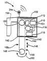
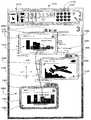
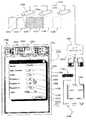
도 1은 마스터 프리젠테이션 유니트과 제 1 및 제 2 슬래브 프리젠테이션 유니트들을 포함하는 본 발명의 일 실시예에 따른 전형적인 플립차트 미미킹 시스템의 사시도이다.1 is a perspective view of an exemplary flipchart marking system according to an embodiment of the present invention including a master presentation unit and first and second slab presentation units.

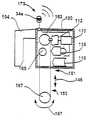
도 2는 도 1의 마스터 프리젠테이션 유니트의 확대 사시도이다.FIG. 2 is an enlarged perspective view of the master presentation unit of FIG. 1.

도 3은 도 2의 마스터 유니트의 개략적 부분 단면도이다.3 is a schematic partial cross-sectional view of the master unit of FIG. 2.

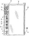
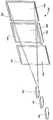
도 4는 도 1의 슬래브 유니트들중 한 유니트의 사시도이다.4 is a perspective view of one of the slab units of FIG.

도 5는 도 4의 슬래브 프리젠테이션 유니트의 개략적 부분 단면도이다.5 is a schematic partial cross-sectional view of the slab presentation unit of FIG. 4.

도 6은 도 1의 마스터 유니트과 함께 사용될 수 있는 슬래브 유니트의 제 2 실시예의 사시도이다.6 is a perspective view of a second embodiment of a slab unit that may be used with the master unit of FIG.

도 7은 비록 다른 전형적인 슬래브 프리젠테이션 유니트 설계를 기술하지만 도 5의 도면과 유사한 도면이다.FIG. 7 is a view similar to that of FIG. 5, although describing another typical slab presentation unit design.

도 8은 비록 하나의 부가 슬래브 프리젠테이션 유니트을 기술하지만 도 7과 유사한 도면이다.FIG. 8 is a view similar to FIG. 7 although describing one additional slab presentation unit.

도 9는 비록 또 다른 하나의 부가 슬래브 프리젠테이션 유니트 실시예를 기술하지만 도 9과 유사한 도면이다.FIG. 9 is a view similar to FIG. 9 although describing another additional slab presentation unit embodiment.

도 10a는 도 1에 도시된 핸드헬드 인터페이스 유니트의 사시도이다.10A is a perspective view of the handheld interface unit shown in FIG. 1.

도 10b는 도 10a의 인터페이스 유니트의 일 실시예를 구성하는 컴포넌트들의 개략도이다.FIG. 10B is a schematic diagram of components that make up an embodiment of the interface unit of FIG. 10A.

도 11은 비록 다른 타입의 슬래브 프리젠테이션 유니트을 포함하는 시스템을 기술하지만 도 1과 유사한 도면이다.FIG. 11 is a view similar to FIG. 1, although describing a system including other types of slab presentation units.

도 12는 비록 평면 패널 디스플레이들을 포함하는 슬래브 프리젠테이션 유니트들을 기술하지만 도 1과 유사한 도면이다.FIG. 12 is a view similar to FIG. 1 although describing slab presentation units including flat panel displays.

도 13은 도 1 내지 도 12에 도시된 시스템들중 어느 하나와 함께 사용될 수 있는 본 발명의 일 양상에 따른 플립핑 방법을 기술한 흐름도이다.13 is a flow chart describing a flipping method according to one aspect of the present invention that may be used with any of the systems shown in FIGS.

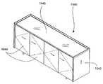
도 14는 슬래브 유니트으로부터 이미지들을 검색하고 마스터 유니트을 통해 이미지들을 재표시하기 위하여 도 13에 기술된 방법의 일부분으로 대체될 수 있는 서브-프로세스를 기술한 도면이다.FIG. 14 is a diagram describing a sub-process that may be replaced as part of the method described in FIG. 13 to retrieve images from the slab unit and to redisplay the images via the master unit.

도 15는 마스터 유니트으로부터 슬래브 유니트으로 이미지들을 플립핑하고 슬래브 유니트으로부터 이미지를 검색하며 슬래브 유니트이 고유하게 식별가능한 방법을 기술한 도면이다.FIG. 15 is a diagram illustrating how to flip images from a master unit to a slab unit, retrieve an image from the slab unit, and uniquely identify the slab unit.

도 16은 마스터 프리젠테이션 유니트 및 슬래브 프리젠테이션 유니트들을 통해 현재 디스플레이되는 이미지들이 고속으로 저장된후 저장전에 이미지들을 표시한 동일한 유니트들을 통해 재액세스 및 재표시되는 방법을 기술한 흐름도이다.FIG. 16 is a flow chart illustrating how images currently displayed via the master presentation unit and slab presentation units are stored at high speed and then re-accessed and redisplayed through the same units displaying images before storage.

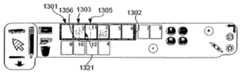
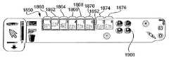
도 17은 비록 다른 타입의 제어 버튼들을 포함하는 마스터 유니트을 기술하지만 도 2와 유사한 도면이다.FIG. 17 is a view similar to FIG. 2 although describing a master unit comprising other types of control buttons.

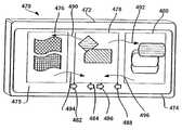
도 18은 플립 차트 활동을 모사하기 위하여 사용될 수 있는 다수의 프리젠테이션 표면들로 표면 공간을 분할하는 단일 프리젠테이션 유니트을 포함하는 본 발명의 임의의 양상들과 일치하는 시스템의 평면도이다.18 is a top view of a system consistent with any aspect of the present invention that includes a single presentation unit that divides surface space into multiple presentation surfaces that can be used to simulate flip chart activity.

도 19는 비록 표시된 이미지들이 다른 방식으로 관리되는 다른 시스템을 기술하지만 도 18과 유사한 도면이다.FIG. 19 is a view similar to FIG. 18 although describing another system in which the displayed images are managed in a different manner.

도 20은 3개의 프로젝터들 및 연관된 투영 스크린들/어셈블리들을 포함하는 다른 실시예의 사시도이다.20 is a perspective view of another embodiment that includes three projectors and associated projection screens / assemblies.

도 21은 마스터 유니트이 이젤(easel) 어셈블리의 형태를 가지며 슬래브 유니트들이 장착된 벽인 또 다른 실시예를 기술한 도면이다.FIG. 21 illustrates another embodiment where the master unit is in the form of an easel assembly and the wall on which the slab units are mounted.

도 22는 원격적으로 위치한 마스터 및 슬래브 유니트들을 사용하여 프리젠테이션을 원격적으로 제어하기 위하여 인터페이스 유니트이 사용되는 시스템을 기술 한 개략도이다.22 is a schematic diagram illustrating a system in which an interface unit is used to remotely control a presentation using remotely located master and slab units.

도 23은 주 이미지 및 2개의 플립핑된 이미지들을 투영하는 단일 프로젝터를 포함하는 하나의 전형적인 부가 시스템을 기술한 개략도이다.FIG. 23 is a schematic diagram illustrating one exemplary additional system including a single projector projecting a main image and two flipped images.

도 24는 휴대용 다중 평면 패널 디스플레이들을 포함하는데 이 디스플레이들중 하나가 마스터 디스플레이로서 선택되고 다른 디스플레이들 또는 부세트가 슬래브 디스플레이로서 사용되는 다른 전형적인 시스템을 기술한 개략도이다.FIG. 24 is a schematic diagram illustrating another exemplary system including portable multi-flat panel displays in which one of the displays is selected as the master display and the other displays or subsets are used as the slab display.

도 25는 본 발명의 적어도 일부 양상들에 따른 또 다른 방법을 기술한 흐름도이다.25 is a flowchart describing another method in accordance with at least some aspects of the present invention.

도 26은 비록 휴대용 유니트들중 하나가 마스터 유니트으로서 선택된후 시스템을 기술하지만 도 24와 유사한 도면이다.FIG. 26 is a view similar to FIG. 24 although describing the system after one of the portable units has been selected as the master unit.

도 27은 비록 슬래브 유니트들이 선택된후 시스템을 도시하지만 도 26와 유사한 도면이다.FIG. 27 is a view similar to FIG. 26 although the system is shown after slab units have been selected.

도 28은 단일 평면 패널 디스플레이 휴대용 유니트 및 플립핑된 이미지들을 투영하는 다중 프로젝터들을 포함하는 또 다른 실시예를 기술한 도면이다.FIG. 28 illustrates another embodiment including a single flat panel display portable unit and multiple projectors for projecting flipped images.

도 29는 광역 네트워크에 의하여 링크되는, 도 28의 구성과 유사한 두개의 서브시스템들을 포함하는 시스템의 사시도이다.FIG. 29 is a perspective view of a system including two subsystems similar to the configuration of FIG. 28, linked by a wide area network. FIG.

도 30은 평면 패널 디스플레이가 세로방향(portrait orientation) 및 가로방향(landscape orientation)사이에서 회전되도록 장착된, 도 28에 기술된 시스템과 유사한 시스템을 도시하며, 가로방향에 디스플레이를 도시한 개략도이다.FIG. 30 shows a system similar to the system described in FIG. 28, with the flat panel display mounted such that it rotates between portrait orientation and landscape orientation, and is a schematic diagram showing the display in a landscape orientation.

도 31은 비록 가로방향에서 디스플레이를 가진 시스템을 기술하지만 도 30과 유사한 도면이다.FIG. 31 is a view similar to FIG. 30 although describing a system with a display in the landscape orientation.

도 32는 본 발명의 적어도 일 실시예에 따라 마스터 유니트을 통해 표시될 수 있는, 세로방향의 16:9 종횡비 스크린샷을 도시한 개략도이다.32 is a schematic diagram showing a portrait 16: 9 aspect ratio screenshot, which may be displayed via a master unit in accordance with at least one embodiment of the present invention.

도 33은 본 발명의 적어도 일부 양상들에 따라 슬래브 프리젠테이션 공간을 통해 표시될 수 있는 4개의 슬래브 이미지들의 개략도이다.33 is a schematic diagram of four slab images that may be displayed through a slab presentation space in accordance with at least some aspects of the present invention.

도 34는 도 29에 기술된 랩탑 컴퓨터들중 하나를 통해 제공될 수 있는 스크린샷의 개략도이다.FIG. 34 is a schematic diagram of a screenshot that may be provided via one of the laptop computers described in FIG. 29.

도 35는 도 32의 도구 영역을 더 상세히 도시한 개략도이다.35 is a schematic diagram illustrating the tool area of FIG. 32 in more detail.

도 36은 비록 작업공간 영역에 제공된 부가 정보를 기술하지만 도 32의 도면과 유사한 개략도이다.FIG. 36 is a schematic diagram similar to the diagram of FIG. 32 although describing additional information provided in the workspace area.

도 37은 비록 작업공간 영역에 추가된 부가 정보 및 감소된 크기의 초기 이미지를 기술하지만 도 32의 도면과 유사한 도면이다.FIG. 37 is a view similar to the diagram of FIG. 32 although it describes additional information added to the workspace area and an initial image of reduced size.

도 38은 비록 작업공간 영역으로부터 패널 아이콘으로의 정보의 일부의 이동에 대응하는 활동을 기술하지만 도 32의 도면과 유사한 개략도이다.FIG. 38 is a schematic diagram similar to the diagram of FIG. 32 although describing activity corresponding to the movement of some of the information from the workspace area to the panel icon.

도 39는 비록 정보가 제거된 작업공간 영역의 이미지를 기술하지만 도 38과 유사한 도면이다.FIG. 39 is a view similar to FIG. 38 although an image of the workspace area from which information has been removed.

도 40은 비록 디스플레이 유니트이 세로방향으로부터 가로방향으로 회전된후에 16:9 종횡비 스크린샷을 기술하지만 도 32의 도면과 유사한 개략도이다.FIG. 40 is a schematic view similar to the diagram of FIG. 32 although a 16: 9 aspect ratio screenshot is depicted after the display unit has been rotated from portrait to landscape.

도 41은 비록 가로방향의 슬래브 이미지들을 기술하지만 도 33과 유사한 도면이다.FIG. 41 is a view similar to FIG. 33, although describing slab images in the transverse direction. FIG.

도 42는 비록 세로방향에서의 4:3 종횡비 스크린샷을 기술하지만 도 32의 도면과 유사한 개략도이다.FIG. 42 is a schematic similar to the diagram of FIG. 32 although depicting a 4: 3 aspect ratio screenshot in portrait orientation.

도 43은 비록 가로방향에서의 4:3 종횡비 스크린샷을 기술하지만 도 42와 유사한 도면이다.FIG. 43 is a view similar to FIG. 42 although depicting a 4: 3 aspect ratio screenshot in landscape.

도 44는 도 35에 기술된 영역과 유사한 다른 전형적인 도구 영역 뿐만아니라 도구 영역의 패널 아이콘들과 연관된 6개의 슬래브 프리젠테이션 공간들을 도시한 개략도이다.FIG. 44 is a schematic diagram showing six slab presentation spaces associated with panel icons of the tool area as well as other typical tool areas similar to the area described in FIG. 35.

도 45는 비록 도구 영역 및 연관된 슬래브 프리젠테이션 공간들을 다른 상태로 기술하지만 도 44와 유사한 도면이다. FIG. 45 is a view similar to FIG. 44 although the tool area and associated slab presentation spaces are described in different states.

도 46은 비록 다른 상태로 기술하였지만 도 44의 도구 영역과 유사한 도면이다.FIG. 46 is a view similar to the tool area of FIG. 44 although described in other states.

도 47은 비록 도구 영역 및 슬래브 프리젠테이션 공간들을 다른 상태로 기술하지만 도 44와 유사한 도면이다.FIG. 47 is a view similar to FIG. 44 although the tool area and slab presentation spaces are described in different states.

도 48은 비록 다른 상태로 도구 영역을 기술하지만 도 46과 유사한 도면이다.FIG. 48 is a view similar to FIG. 46 although the tool region is described in a different state.

도 49는 비록 도구 영역 및 슬래브 프리젠테이션 공간들을 또 다른 상태로 기술하지만 도 44와 유사한 도면이다.FIG. 49 is a view similar to FIG. 44 although the tool area and slab presentation spaces are described in another state.

도 50은 적어도 일부 실시예들에 따라 1차 및 2차 슬래브 표현 영역들 뿐만아니라 두개의 링크된 원격 시스템들에 대응하는 슬래브 프리젠테이션 공간들의 2개의 다른 세트들을 포함하는, 도 44의 도구 영역의 다른 버전을 기술한 도면이다.FIG. 50 of the tool region of FIG. 44 includes two different sets of slab presentation spaces corresponding to two linked remote systems as well as primary and secondary slab representation regions in accordance with at least some embodiments. A diagram describing another version.

도 51은 비록 비교적 큰 슬래브 표현 영역을 포함하지만 도구 영역을 도시한 도면이다.FIG. 51 shows the tool area although it includes a relatively large slab presentation area.

도 52는 적어도 일부 진보적 실시예들에 따라 프린트 윈도우를 포함하는 스크린샷을 도시한 도면이다.52 illustrates a screenshot including a print window in accordance with at least some advanced embodiments.

도 53은 네트워킹된 컴퓨터 장치들과 연관된 프린팅 장치들을 식별하는 방법을 기술한 흐름도이다.53 is a flow chart describing a method of identifying printing devices associated with networked computer devices.

도 54는 적어도 일부 진보적인 실시예들에 따른 프린트 방법을 기술한 흐름도이다.54 is a flow chart describing a printing method according to at least some advanced embodiments.

도 55는 세션 이미지들의 전자 카피(copy)들의 분배를 용이하게 하는 룸 위자드를 기술한 개략도이다.FIG. 55 is a schematic diagram illustrating a room wizard that facilitates distribution of electronic copies of session images.

도 56은 컨퍼런스 참가자들의 이메일 주소들을 식별하여 저장하는 방법을 기술한 흐름도이다.56 is a flow chart illustrating a method of identifying and storing email addresses of conference participants.

도 57은 세션 이미지들의 전자 버전들을 컨퍼런스 참가자들에게 전송하는 방법을 기술한 흐름도이다.57 is a flowchart describing a method of transmitting electronic versions of session images to conference participants.

도 58은 전형적인 휴대용 및 자체 포함 컨퍼런스 프리젠테이션 유니트의 사시도이다.58 is a perspective view of a typical portable and self-contained conference presentation unit.

도 59는 비록 다른 휴대 실시예를 기술하지만 도 58과 유사한 도면이다.FIG. 59 is a view similar to FIG. 58, although describing another portable embodiment.

도 60은 디스플레이 유니트, 광 감지 장치, 무선 수신기를 도시하며, 쌍방향성이 디스플레이 표면과 상호작용하기 위하여 사용된 객체의 함수인 디스플레이 표면과의 상호작용을 용이하게 하는 방법을 기술한 개략도이다.60 is a schematic diagram illustrating a display unit, a light sensing device, and a wireless receiver, illustrating a method of facilitating interaction with a display surface as a function of interactiveness used to interact with the display surface.

도 61은 적어도 일부 진보적 실시예들에 따른 도움(help) 피처를 도시한 도면이다.FIG. 61 illustrates a help feature in accordance with at least some advanced embodiments.

도 62는 도움 기능이 사용되는 다수의 슬래브 프리젠테이션 공간들 및 마스터 유니트 스크린샷을 기술한 개략도이다.FIG. 62 is a schematic diagram illustrating a master unit screenshot and a number of slab presentation spaces in which a help function is used.

도 63은 프로젝터 밝기 제어가 마스터 유니트 스크린샷을 통해 용이하게 수행되는 시스템을 기술한 개략도이다.63 is a schematic diagram illustrating a system in which projector brightness control is easily performed through a master unit screenshot.

도 64는 마스터 유니트 스크린샷이 룸 또는 환경 장치를 제어하기 위하여 사용되는 시스템의 개략도이다.64 is a schematic diagram of a system in which a master unit screenshot is used to control a room or environmental device.

도 65는 마스터 프리젠테이션 유니트을 통해 구현될 수 있는 여러 부가 피처들을 기술한 스크린샷을 도시한 도면이다.FIG. 65 is a screenshot illustrating various additional features that may be implemented via a master presentation unit.

도 66은 비록 부가 피처들 및 적어도 일부 실시예들의 양상들을 기술하지만 도 65와 유사한 도면이다.FIG. 66 is a view similar to FIG. 65, although describing additional features and aspects of at least some embodiments.

도 67은 비록 다른 조건들하에서의 상태를 기술하지만 도 44에 기술된 영역에 유사한 도구 영역을 도시한 개략도이다.FIG. 67 is a schematic diagram showing a similar tool area to the area described in FIG. 44 although describing conditions under other conditions.

도 68은 비록 다른 조건들하에서의 상태를 기술하지만 도 67과 유사한 개략도이다.FIG. 68 is a schematic diagram similar to FIG. 67 although describing conditions under other conditions.

도 69는 비록 다른 조건 세트들하에서의 상태를 기술하지만 도 67과 유사한 개략도이다.69 is a schematic diagram similar to FIG. 67, although describing the conditions under other sets of conditions.

도 70은 적어도 하나의 진보적인 실시예에 따른 프로젝터 어셈블리를 포함하는 크레덴자(credenza)의 사시도이다.70 is a perspective view of a credenza including a projector assembly according to at least one advanced embodiment.

도 71은 상부 부재 및 도어(door) 부재들이 제거된 도 70의 크레덴자 어셈블리를 도시한 도면이다.FIG. 71 shows the cradenza assembly of FIG. 70 with the top and door members removed. FIG.

도 72는 프로젝터 어셈블리가 환영으로 도시된 벽 구조에 인접한 도 70의 크레덴자 어셈블리를 도시한 도면이다.FIG. 72 is a view of the cradenza assembly of FIG. 70 adjacent to a wall structure in which the projector assembly is shown as welcome.

도 73은 비록 사용자가 이미지의 주변 에지를 따라 부가 정보를 추가하도록 작업 공간에 디스플레이된 이미지의 크기가 감소되어야 할때를 결정하기 위하여 사용되는 프레임 또는 경계 라인이 환영으로 도시하지만 도 65의 이미지와 유사한 스크린샷을 도시한 도면이다.73 shows the illusion of the frame or boundary line used to determine when the size of the image displayed in the workspace should be reduced so that the user adds additional information along the peripheral edge of the image. A similar screenshot is shown.

도 74는 비록 사용자가 주변 에지들의 이미지에 부가 정보를 추가하도록 작업공간에 표시된 이미지의 크기가 감소되었을지라도 도 73의 이미지와 유사한 스크린샷을 도시한 도면이다.FIG. 74 shows a screenshot similar to the image of FIG. 73 although the size of the image displayed in the workspace has been reduced so that the user adds additional information to the image of the peripheral edges.

도 75는 활동이 계속될 수 있도록 활동을 변경한 최근 이미지와 최근 팁을 재정렬하는데 있어서 사용자에게 도움을 줄 수 있는 시프팅 활동 및 감소된 크기의 이미지를 도시한 개략도이다.FIG. 75 is a schematic diagram illustrating shifted activities and reduced sized images that may assist a user in reordering recent tips and recent tips that have changed activity so that the activity may continue.

도76은 감속된 크기의 이미지가 스타일러스 팁으로 정렬하도록 편이되었지만 도75와 유사한 개략도이다.FIG. 76 is a schematic similar to FIG. 75 although the reduced sized image is biased to align with the stylus tip.

도77은 적어도 일부의 예측된 실시예와 일치하는 노트 요약을 설명하는 스크린 샷이다.77 is a screenshot illustrating a note summary consistent with at least some predicted embodiment.

본 발명이 몇몇 상이한 형태로 실시될 수도 있지만, 본 발명은 설명된 특정 실시예를 통해 본 발명이 이해되도록 하기 위해 설명되었으며, 본 발명이 한정되는 것을 의도하지 않는다.Although the invention may be practiced in several different forms, the invention has been described in order to enable the invention to be understood through the specific embodiments which have been described and are not intended to be limiting of the invention.

유사한 참조 번호는 몇몇 도면을 통해 유사한 구성 요소를 나타내며, 특히 도1을 참조하면, 설명된 시스템 구성 요소는 청중에게 정보를 제공하기 위해 및/또는 시스템 조작자와 청중 사이의 협력적인 동작을 용이하게 하기 위해 소정의 공간에서 사용될 수도 있는 반면, 상기 설명을 간략하게 하기 위해, 시스템 및 구성 요소는 일반적으로 회의실(11)의 전면에 위치한 프리젠테이션 벽(12), 회의실(11)에 진입 및 진출을 위한 출입문(14), 및 번호(16 및 18)로 표시된 다수의 회의 테이블 및 책상을 포함하는 예로든 회의실의 환경에서 설명된다. 테이블(16 및 18)은 벽(12)에 인접한 회의실(11)의 전면에서 청중에게 제공된 정보를 용이하게 주시하도록 회의실(11) 내의 청중들이 일정방향으로 향하도록 회의실(11) 내의 좌석(미도시)에 따라 배열된다.Like reference numerals refer to like elements throughout the several views, and in particular with reference to FIG. 1, the described system elements may be used to provide information to an audience and / or to facilitate cooperative operation between the system operator and the audience. While the above description may be used in a predetermined space, in order to simplify the above description, the system and components are generally used for entering and exiting thepresentation wall 12, themeeting room 11, which is generally located in front of themeeting room 11; It is described in the context of an example conference room that includes adoor 14, and a number of conference tables and desks indicated bynumbers 16 and 18. The tables 16 and 18 are seats in the meeting room 11 (not shown) to direct the audience in themeeting room 11 in a direction so that the information provided to the audience is easily viewed from the front of themeeting room 11 adjacent to thewall 12. Are arranged according to

본 발명의 일 실시예에서, 긴 수평 레일(40)이 벽(12)에 인접한 마스터 및 슬래브 프리젠테이션 유니트을 일시적으로 또는 영구적으로 지지하기 위해 회의실(11) 내의 마루 위 6 내지 7 피트 정도에서 벽(12)에 장착된다. 도3을 참조하면, 레일(40)은 높이 디멘존(H1) 및 레일(40)의 길이에 수직하고 수평 상부면(41)을 형성하는 폭(W1)을 갖는다. 레일(40)은 이하에서 더욱 상세하게 설명될 본 발명의 유니트 장착 부재의 말단부(예를 들어, 도3의 74)가 벽과 레일(40)의 후면부 사이에서 고정하도록 볼트 등을 포함하는 소정의 고정 부재로 벽(12)에 고정될 수도 있고 벽(12)의 표면으로부터 이격된다.In one embodiment of the present invention, the longhorizontal rail 40 may be mounted at about 6 to 7 feet above the floor in themeeting room 11 to temporarily or permanently support the master and slab presentation units adjacent to thewall 12. 12) is mounted. Referring to FIG. 3, therail 40 has a height dimension zone H1 and a width W1 perpendicular to the length of therail 40 and forming a horizontalupper surface 41. Therail 40 may include a bolt or the like to secure the distal end of the unit mounting member of the present invention (eg, 74 in FIG. 3) to be fixed between the wall and the rear portion of therail 40, which will be described in more detail below. The fixing member may be fixed to thewall 12 and spaced apart from the surface of thewall 12.

다시 도1을 참조하면, 예로든 제1 시스템(10)은 마스터 프리젠테이션 유니트(28) 및 제1 및 제2 슬래브 프리젠테이션 유니트(22a 및 22b)을 각각 포함한다. 도1에 도시된 바와 같이, 각각의 프리젠테이션 유니트(28, 22a, 22b 등)은 전방 프리젠테이션 표면(일반적으로 번호 48 또는 소문자가 붙은 번호 48로 표시됨)이 회의실(11) 내의 청중에 의해 쉽게 주시될 수 있도록 벽(12)에 인접한 레일(40)에 장착되고 레일에 매달린다. 도2 및 도3을 참조하면, 마스터 프리젠테이션 유니트(28)은 전자 이미지 형성 장치로서, 실시예에서는 일반적으로 강고한 직선 및 상대적으로 얇은 플라스틱 또는 금속 하우징 어셈블리(52)에 장착된 평판 플라즈마 또는 액정 타입 디스플레이 스크린(48), 트랜시버(20) 및 제1 및 제2 마운팅 훅 또는 부재(각각 72, 74)를 포함한다.Referring again to FIG. 1, the exemplaryfirst system 10 includes amaster presentation unit 28 and first and secondslab presentation units 22a and 22b, respectively. As shown in Fig. 1, eachpresentation unit 28, 22a, 22b, etc. has a front presentation surface (typically indicated bynumber 48 or lowercase number 48) that is easily accessible by the audience in theconference room 11. It is mounted on arail 40 adjacent to thewall 12 and suspended from the rail so that it can be viewed. Referring to Figures 2 and 3, themaster presentation unit 28 is an electronic image forming device, which in the embodiment is generally a flat plasma or liquid crystal mounted on a rigid straight line and relatively thin plastic ormetal housing assembly 52.Type display screen 48,transceiver 20 and first and second mounting hooks or members (72, 74, respectively).

또한 도3을 참조하면, 하우징(52)은 각각 대향하는 전면부 및 후면부(53 및 55)를 포함한다. 폭 디멘존(W2) 및 높이 디멘존(H2)을 갖는 스크린의 전면(54)이 주시될 수 있도록 스크린(48)이 장착된 개구(57)를 형성한다. 장착 부재(72 및 74)는 후면부(55)와 말단부의 대향면(대향면들 중 하나는 도3에서 번호(59)로 표시됨) 사이에서 채널(17 및 19)을 형성하도록 후면부(55)의 대향 측면 상부 코너로부터 연장하고 후면부의 말단부에서 아래로 연장한다. 각각의 채널(17, 19)은 레일(40)의 폭 디멘존(W1)에 실질적으로 유사한 리세스 디멘존(R1)을 갖는다(도3 참조).Also referring to FIG. 3, thehousing 52 includes opposing front andrear portions 53 and 55, respectively. Anopening 57 is provided on which thescreen 48 is mounted so that thefront face 54 of the screen with the width dimension zone W2 and the height dimension zone H2 can be viewed. The mountingmembers 72 and 74 are formed of therear portion 55 to formchannels 17 and 19 between therear portion 55 and the opposing face of the distal end (one of which is indicated by thenumber 59 in FIG. 3). It extends from the opposing side upper corner and extends down at the distal end of the back. Eachchannel 17, 19 has a recess dimension R1 substantially similar to the width dimension zone W1 of the rail 40 (see FIG. 3).

마스터 유니트(28)을 레일(40)에 장착하기 위해, 도1 및 도3에 명확히 도시된 바와 같이, 유니트(28)은 부재(72 및 74)에 의해 형성된 채널이 레일(40) 위에 위치하도록 레일(40)과 관련하여 리프팅되고 위치설정된다. 그 후, 유니트(28)은 레일(40)의 부분이 부재(72 및 74)에 의해 형성된 채널 내에서 수신될 때까지 그리고 부재(72 및 74)가 일반적으로 상부 레일 표면(41) 상에 지지되도록 낮춰진다. 비록 도시되지는 않았지만, 벽(12) 표면에 접촉하고 실질적으로 수직인 방향으로 유니트(28)을 견고하게 하기 위해 하단부에 가장 가까운 후면부(55)로부터 연장하는 하나 이상의 추가 연장 부재가 제공될 수도 있다.In order to mount themaster unit 28 to therails 40, as clearly shown in FIGS. 1 and 3, theunit 28 has a channel formed by themembers 72 and 74 positioned above therails 40. Lifted and positioned in relation to therail 40. Thereafter, theunit 28 is supported until the portion of therail 40 is received in the channel formed by themembers 72 and 74 and themembers 72 and 74 are generally supported on theupper rail surface 41. As low as possible. Although not shown, one or more additional extension members may be provided that extend from therear portion 55 closest to the lower end to contact thewall 12 surface and to firm theunit 28 in a substantially vertical direction. .

도3을 다시 참조하면, 전술한 구성 요소 외에도, 예로든 마스터 프리젠테이션 유니트(28)은 프로세서(80), 키보드 또는 다른 타입의 제어 인터페이스(30)(즉, 키보드는 상호 작용이 선택가능한 온 스크린 아이콘 등과 같은 다른 수단을 통해 제공되는 경우 불필요함) 및 디지털 메모리(88)를 포함한다. 프로세서(80) 및 메모리(88)는, 키보드(30)가 하우징 구조에 의해 지원된 키를 포함하는 반면, 하우징(52)에 의해 형성된 캐비티(61) 내에 장착된다. 프로세서(80)는 각각의 송수신기(20), 디스플레이 스크린(48), 키보드(30) 및 메모리(88)에 다수의 데이터 버스(도면 번호 미표시)를 통해 링크된다. 일반적으로, 송수신기(20)는 몇몇 상이한 무선 기술(예를 들어, RF 인터페이스 등)을 통해, 그리고 송수신기(20) 부근(예를 들어, 회의실(11)에 의해 한정된 공간 내)에 몇몇 상이한 무선 통신 프로토콜(예를 들어, 802.11b, 블루투스 등)을 통해 정보를 송신 및 수신할 수 있다.Referring again to FIG. 3, in addition to the components described above, the exemplarymaster presentation unit 28 may include aprocessor 80, a keyboard or other type of control interface 30 (i.e., the keyboard may be interactively selected on-screen). Unnecessary if provided via other means such as an icon or the like) and adigital memory 88. Theprocessor 80 and thememory 88 are mounted in thecavity 61 formed by thehousing 52, while thekeyboard 30 includes the keys supported by the housing structure.Processor 80 is linked to eachtransceiver 20,display screen 48,keyboard 30, andmemory 88 through a number of data buses (not shown). In general, thetransceiver 20 is via several different radio technologies (eg, RF interface, etc.) and several different wireless communications in the vicinity of the transceiver 20 (eg, in a space defined by the conference room 11). Information can be sent and received via protocols (eg 802.11b, Bluetooth, etc.).

메모리(88)는 디지털 메모리 장치이며 다양한 방법을 실행하기 위해 프로세서(80)에 의해 사용가능한 정보의 다수의 상이한 타입을 포함한다. 일반적으로 메모리(88)에 저장된 정보는 프로세서(80)에 의해 실행된 프로그램 및 디스플레이 스 크린(48)을 통해 제공된 이미지와 같은 데이터를 포함하는 두 형태를 취한다. 프로세서(80)에 의해 실행된 프로그램은 적어도 일부의 경우, 스크린(48)에 정보를 부가하고 스크린으로부터 정보를 삭제함은 물론 디스플레이(48)를 통해 정보를 제공하기 위해 드라이버 프로그램을 디스플레이하기 위해, 가상 잉크 펜 및 가상 잉크 타입 소거 장치의 위치를 감지하는 위치 감지 프로그램을 포함한다.Thememory 88 is a digital memory device and includes many different types of information available by theprocessor 80 to carry out various methods. In general, the information stored in thememory 88 takes two forms, including data such as a program executed by theprocessor 80 and an image provided through thedisplay screen 48. The program executed by theprocessor 80 is at least in some cases virtual to display the driver program for adding information to and removing information from thescreen 48 as well as providing information through thedisplay 48. And a position sensing program for sensing the position of the ink pen and the virtual ink type erasing apparatus.

게다가, 메모리(88)는 디스플레이(48)를 통해 제공된 이미지를 관리하기 위해 사용된 프로그램을 포함한다. 예를 들어, 본 발명의 적어도 일부의 실시예에서, 메모리(88)의 프로그램은 유니트(28)으로부터 플립된 각각의 이미지에 대한 유일한 식별 번호 등을 슬래브 프리젠테이션 유니트들 중 하나에 할당하고 연속한 액세스를 위해 메모리(88) 내에 각각의 플립된 이미지 및 대응하는 식별자 번호를 저장할 수도 있다. 다른 예로서, 이미지가 슬래브 프리젠테이션 유니트들 중 특정한 하나에 플립될 때, 마스터 유니트 프로세서(80)는 플립된 이미지를 이미지가 플립되는 슬래브 유니트을 유일하게 식별하는 유니트 식별자와 상관시키거나 저장하도록 프로그래밍될 수도 있다. 식별자 및 이미지가 메모리(88)에 저장된 후, 이미지는 유일한 식별자에 대한 참조를 통해 액세스될 수도 있다.In addition, thememory 88 includes a program used to manage images provided via thedisplay 48. For example, in at least some embodiments of the present invention, the program in thememory 88 assigns a unique identification number and the like for each image flipped from theunit 28 to one of the slab presentation units and successively. Each flipped image and corresponding identifier number may be stored inmemory 88 for access. As another example, when an image is flipped to a particular one of the slab presentation units, themaster unit processor 80 may be programmed to correlate or store the flipped image with a unit identifier that uniquely identifies the slab unit to which the image is flipped. It may be. After the identifier and image are stored inmemory 88, the image may be accessed via a reference to a unique identifier.

더욱이, 본 발명의 적어도 일부의 실시예에서, 파워 포인트, 다양한 스프레드 시트 애플리케이션, CAD 애플리케이션, 워드 프로세서 애플리케이션, 인터넷 브라우져 애플리케이션 등과 같은 통상의 소프트웨어 애플리케이션의 사본이 프로세서에 의해 액세스 및 실행되기 위해 메모리(88) 내에 저장될 수도 있다. 여기서, 적어도 일부의 실시예에서, 통상의 소프트웨어 애플리케이션은 시스템(10)에 사용 가능하지 않을 수도 있으며, 이 경우, 통상의 애플리케이션의 사본은 메모리(88)에 저장되지 않을 것을 이해해야 한다. 더욱이, 적어도 일부의 실시예에서, 프로세서(80)가 통상의 소프트웨어 애플리케이션에 대응하는 이미지를 디스플레이하기 위해 사용되는 동안, 프로세서(80) 그 자체는 소프트웨어 애플리케이션을 실행하지 않도록, 파워 포인트, 스프레드 시트 등과 같은 소프트웨어 애플리케이션은 마스터 프리젠테이션 유니트(28)에 사용가능한 팜 또는 랩탑 타입 컴퓨터에 저장 또는 이를 통해 액세스될 수도 있음을 이해해야 한다. 여기서, 컴퓨터는 프로그램을 실행시킬 것이며, 디스플레이(48)를 구동시키기 위해 프로세서(80)에 정보를 제공할 것이다.Moreover, in at least some embodiments of the invention, copies of conventional software applications, such as PowerPoint, various spreadsheet applications, CAD applications, word processor applications, Internet browser applications, and the like, may be accessed by the processor in order to access and executememory 88. May be stored in the Here, in at least some embodiments, it should be understood that conventional software applications may not be available tosystem 10, in which case a copy of the typical application will not be stored inmemory 88. Moreover, in at least some embodiments, while theprocessor 80 is used to display an image corresponding to a typical software application, theprocessor 80 itself does not execute the software application, such as power point, spreadsheet, etc. It should be understood that the same software application may be stored on or accessed through a palm or laptop type computer available to themaster presentation unit 28. Here, the computer will execute the program and provide information to theprocessor 80 to drive thedisplay 48.

도3을 참조하면, 제어 인터페이스(30)는 다양한 타입의 입력 장치를 포함할 수도 있다. 예를 들어, 적어도 일부의 실시예에서, 도2에 도시된 키와 같은 기계적 하드웨어 타입 버튼은 플립 명령(즉, 현재 디스플레이(48) 상의 이미지가 슬래브 프리젠테이션 유니트에 전송되고 이어 디스플레이(48)로부터 제거되는 명령) 및 다른 데이터 액세스 및 프로그램 제어 명령과 같은 명령들을 프로세서(80)에 제공하기 위해 하우징(52)의 전면부(53) 내에 제공될 수도 있음이 고려된다. 택일적으로, 또는 하드웨어 타입 버튼에 부가하여, 적어도 일부의 실시예에서, 선택시 프로세스를 실행하도록 프로세서(80)에 명령 신호를 제공할 때, 터치 가능한 아이콘이 시스템 연산자에 의한 선택을 위해 디스플레이 스크린(48)에 제공될 수도 있음을 고려해야 한다. 소정의 경우, 입력 장치(30)는 마크가 스크린(48) 상의 이미지에 부가되거나 삭제될 수 있도록 이미지 확대 성능(즉, 부분적으로 확대 인터페이스 임)을 포함할 수도 있다. 이를 위해, "Electronic Whiteboard"라는 명칭으로 2003년 6월 2일 출원된 미국 특허 출원 10/452,178을 참조할 수 있으며, 이는 본 명세서에 참조된다. 택일적으로, 적어도 일부의 실시예에서, 마스터 유니트(28)으로의 입력은 팜 또는 랩탑 타입 컴퓨팅 장치(예를 들어, 휴대용 제어 인테페이스)를 통할 수도 있으며, 프로세서(80)로의 명령은 송수신기(20)를 통해 수신된다.Referring to FIG. 3, thecontrol interface 30 may include various types of input devices. For example, in at least some embodiments, a mechanical hardware type button, such as the key shown in FIG. 2, is a flip command (ie, the image on thecurrent display 48 is sent to the slab presentation unit and then from thedisplay 48. It is contemplated that it may be provided within thefront portion 53 of thehousing 52 to provide theprocessor 80 with instructions such as instructions to be removed) and other data access and program control instructions. Alternatively, or in addition to a hardware type button, in at least some embodiments, when providing a command signal to theprocessor 80 to execute a process upon selection, a touchable icon is displayed on the display screen for selection by the system operator. Consideration may be given to (48). In some cases,input device 30 may also include an image magnification capability (ie, partly magnification interface) such that marks can be added to or deleted from the image onscreen 48. To this end, reference may be made toUS patent application 10 / 452,178, filed June 2, 2003, entitled “Electronic Whiteboard”, which is incorporated herein by reference. Alternatively, in at least some embodiments, input tomaster unit 28 may be through a palm or laptop type computing device (eg, a portable control interface), and instructions toprocessor 80 may be transmitted totransceiver 20. Is received via).

이하에서는, 본 설명을 간략하게 하기 위해, 다르게 표시되지 않으면, 마스터 유니트(28)은 기계식 키보드(30)를 포함하는 것으로 간주한다. 또한, 다르게 한정되지 않으면, 팜 및 랩탑 컴퓨터 및 제어 장치는 일반적으로 휴대용 장치(HHD)를 의미할 것이다. 더욱이, 유니트 및 장치 통신이 배선될 수도 있지만, 모든 유니트 및 장치 통신은 무선 프로토콜 및 송수신기(예를 들어 도2의 20)를 통하는 것으로 가정한다.In the following, in order to simplify the present description, unless otherwise indicated, themaster unit 28 is considered to include amechanical keyboard 30. Also, unless otherwise defined, palm and laptop computer and control devices will generally mean portable devices (HHD). Moreover, although unit and device communications may be wired, it is assumed that all unit and device communications are via wireless protocols and transceivers (eg, 20 in FIG. 2).

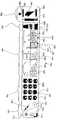
도1 및 2를 다시 참조하면, 예로든 마스터 유니트 키보드 키는 재시작 키(56), 전송 또는 플립 키(58), 저장 키(60), 복원 키(62), 좌측 전송 키(68), 우측 전송 키(70), 및 다수의 패(67)를 포함한다. 개시되고 도시된 선택가능한 키들은 단지 예일 뿐이며, 많은 경우 부가의 선택가능한 키 또는 개시된 키의 서브세트가 디스플레이(48)를 통해 제공될 수도 있으며, 선택가능한 키 세트는 시스템(10)에 의해 지원된 기능 및 적어도 일부의 경우, 시스템 명령의 관련 병치에 의존한다. 게다가, 통상의 소프트웨어 프로그램들이 프로세서(80)에 의해 실행되거나, 디스플레이(48)가 HDD 실행 통상 소프트웨어 프로그램을 위해 큰 디스플레이로서 사용된 경우, 소프트웨어 애플리케이션을 지원하기 위해 요구되는 마우스 또는 터 치 선택가능 아이콘은 디스플레이(48) 상에 나타날 수도 있다.Referring again to Figures 1 and 2, the exemplary master unit keyboard keys include arestart key 56, a transfer or flip key 58, a save key 60, a restore key 62, a left transfer key 68, a right side.Transmission key 70, and a number ofpads 67. The selectable keys disclosed and shown are merely examples, and in many cases additional selectable keys or a subset of the disclosed keys may be provided via thedisplay 48, the selectable key set being supported by thesystem 10. It depends on the functionality and at least in some cases the relevant juxtaposition of system commands. In addition, when conventional software programs are executed by theprocessor 80, or when thedisplay 48 is used as a large display for an HDD running conventional software program, a mouse or touch selectable icon required to support the software application. May appear on thedisplay 48.

도1 및 2를 참조하면, 적어도 일부의 경우, 마스터 프리젠테이션 유니트(28)은 회의실(11) 내의 유니트을 응시하는 청중과 관련하여, 마스터 프리젠테이션 유니트(28)은 슬래브 프리젠테이션 유니트(22a, 22b 등)의 일측에 배치될 수도 있다. 이러한 경우, 디스플레이(48)로부터의 이미지를 슬래브 유니트(22a, 22b 등) 중 하나에 플립하기 위해, 플립된 이미지를 수신하기 위해 슬래브 유니트을 특히 식별하는 소정의 방식이 존재해야 한다. 이러한 실시예에서, 유일한 슬래브 유니트 식별자 "1" 및 "2"는 슬래브 유니트(22a, 22b 등) 중 각각의 하나에 제공되는데, 이들은 조작자가 마스터 유니트과 상호작용함으로써 협력적인 활동을 용이하게 하는 위치에 있을 때 시스템에 의해 쉽게 주시 가능하다. 도1에서, 유니트 식별자 "1" 및 "2"는 각각의 유니트 하우징 어셈블리들의 일단에서 영구적으로 프린트된다.1 and 2, at least in some cases, themaster presentation unit 28 relates to an audience staring at a unit within theconference room 11, such that themaster presentation unit 28 is theslab presentation units 22a, 22b. Or the like). In such a case, in order to flip the image from thedisplay 48 to one of theslab units 22a, 22b, etc., there must be some way to specifically identify the slab unit in order to receive the flipped image. In this embodiment, unique slab unit identifiers "1" and "2" are provided to each one of the slab units (22a, 22b, etc.), where they are located where the operator interacts with the master unit to facilitate cooperative activity. It can be easily watched by the system when there is. In Fig. 1, unit identifiers "1" and "2" are permanently printed at one end of each unit housing assemblies.

본 발명의 예에서, 프로세서(80)는 디스플레이(48) 상의 이미지가 유니트(22a 또는 22b) 중 하나로 플립될 표시에 대해 키보드(30)를 모니터링하기 위해 프로그래밍된다. 이러한 경우, 이미지를 유니트(22a 또는 22b)으로 플립하기 위해, 시스템 조작자는 이미지가 플립되는 유니트에 대응하는 유니트 식별 번호를 선택하기 위해 번호(67)를 사용하고 연속하여 전송 키(58)를 선택하는 것이 고려된다. 예를 들어, 디스플레이(48)로부터의 이미지를 유니트(22a)으로 플립하기 위해, 조작자는 번호 "1"을 선택하기 위해 패드(67)를 사용하고, 이어 키(58)를 선택한다. 유사하게, 이미지를 유니트(22b)으로 플립하기 위해, 조작자는 패드(67)로부터 번호 "2"를 선택하고 연속하여 전송 키(58)를 선택한다.In the example of the present invention, theprocessor 80 is programmed to monitor thekeyboard 30 for an indication on which the image on thedisplay 48 will be flipped to one of theunits 22a or 22b. In this case, in order to flip the image to theunit 22a or 22b, the system operator uses thenumber 67 to select the unit identification number corresponding to the unit to which the image is flipped and subsequently selects thetransmission key 58. Is considered. For example, to flip the image from thedisplay 48 to theunit 22a, the operator uses thepad 67 to select the number " 1 " and selects theear key 58. Similarly, to flip the image to theunit 22b, the operator selects the number "2" from thepad 67 and subsequently selects thetransfer key 58.

여기서, 각각의 개별 어드레싱 가능한 슬래브 유니트 및 또한 소정의 실시예에서, 마스터 유니트(28)은 데이터를 전송하기 위해 사용될 수 있는 유일한 네트워크 어드레스를 갖는다. 예를 들어, 도1에서, 슬래브 유니트(22a 및 22b)에는 유일한 무선 어드레스 "XP45519784" 및 "QZ1433217"이 각각 할당될 수도 있는 반면, 마스터 유니트(28)에는 어드레스 "AM7966142"가 할당된다. 슬래브 스크린의 어드레스들은 유일한 슬래브 유니트 식별자(예를 들어, 본 실시예의 "1" 및 "2")와 상관되며, 상기 상관된 어드레스들 및 식별자들은 마스터 유니트 메모리(88)에 저장된다. 또한, 각각의 슬래브 유니트(22a, 22b 등)의 프로세서들은 무선 신호를 모니터링하고 자신 각각의 네트워크 어드레스로 전송된 무선 신호를 수신한다. 슬래브 유니트이 플립된 이미지에 대해 타겟으로서 선택되면, 프로세서(80)는 타겟 슬래브 유니트과 관련된 네트워크 어드레스를 식별하고, 타겟 슬래브 유니트의 이미지 및 어드레스를 포함하는 이미지 데이터 패킷을 생성하며, 데이터 패킷을 선택된 슬래브 유니트으로 전송하고, 소정의 실시예의 경우, 이미지를 디스플레이(48)로부터 삭제(즉 블랭크 디스플레이(48))하거나 통상의 페이퍼 방식 플립 차트를 모방하는 방식으로 클린 및 클리어 표면(48)을 제공하기 위해 디스플레이(48)를 통해 이미지가 주시 불가능하게 한다. 다른 실시예에서, 제2 확정적 단계는 마스터 이미지가 주기 불가능하게 되는 것을 필요로 할 수도 있다.Here, each individual addressable slab unit and also in some embodiments, themaster unit 28 has a unique network address that can be used for transferring data. For example, in Fig. 1, theslab units 22a and 22b may be assigned unique radio addresses " XP45519784 " and " QZ1433217 " respectively, while themaster unit 28 is assigned an address " AM7966142 ". The addresses of the slab screen are correlated with a unique slab unit identifier (e.g., "1" and "2" in this embodiment), and the correlated addresses and identifiers are stored inmaster unit memory 88. In addition, the processors of eachslab unit 22a, 22b, etc. monitor the radio signals and receive radio signals sent to their respective network addresses. If the slab unit is selected as the target for the flipped image, theprocessor 80 identifies the network address associated with the target slab unit, generates an image data packet containing the image and address of the target slab unit, and sends the data packet to the selected slab unit. To provide a clean andclear surface 48 in a manner that deletes the image from the display 48 (ie, blank display 48) or mimics a conventional paper flip chart. Through 48 makes the image unobservable. In another embodiment, the second deterministic step may require the master image to be nonperiodic.

본 발명의 소정의 실시예에서, 마스터 프리젠테이션 유니트(28)이 슬래브 프리젠테이션 유니트(22a, 22b 등)을 통해 제공된 이미지를 복원하기 위해 사용가능함으로써 상기 이미지들이 편집될 수 있고 편집된 형태로 슬래브 유니트을 통해 제 공될 수 있게 한다. 이를 위해, 도1 내지 도3을 참조하면, 적어도 소정의 실시예에서, 이미지가 마스터 유니트(28)으로부터 슬래브 유니트(22a, 22b 등) 중 하나로 플립되면, 슬래브 유니트에 의해 수신된 이미지 데이터는 슬래브 유니트 메모리에 일시적으로 저장된다(도5의 119 참조).In certain embodiments of the present invention, themaster presentation unit 28 can be used to restore an image provided through theslab presentation units 22a, 22b, etc. so that the images can be edited and slab in edited form. Can be delivered through the unit. For this purpose, referring to FIGS. 1-3, in at least some embodiments, if an image is flipped from themaster unit 28 to one of theslab units 22a, 22b, etc., the image data received by the slab unit is slabed. It is temporarily stored in the unit memory (see 119 in FIG. 5).

이미지가 슬래브 유니트을 통해 제공된 후, 만일 시스템 조작자가 상기 이미지를 편집하기를 원하면, 이미지를 유니트(22b)으로 플립하기 위해 전술한 방식과 유사한 방식으로 시스템 조작자는 번호 패드(67)를 사용하여 슬래브 유니트에 대응하는 식별자 번호를 선택하고 이어 복원 키(62)를 선택한다. 복원 키(62)가 선택되면, 마스터 프로세서(80)는, 이미지를 복원하고 복원 데이터 패킷을 슬래브 유니트으로 무선으로 전송하게 하는 이미지 복원 요청을 포함하는 복원 데이터 패킷 및 슬래브 유니트의 어드레스를 형성한다. 응답으로, 슬래브 유니트은 슬래브 이미지 및 마스터 유니트의 네트워크 어드레스를 포함하는 이미지 데이터 패킷을 생성하고 이미지 데이터 패킷을 마스터 유니트(28)으로 전송한다. 유니트(28)은 이미지 데이터 패킷을 수신하고, 마스터 유니트(28)은 추가의 공동 주시/편집을 위해 디스플레이(48)를 통해 이미지를 제공한다.After the image is provided through the slab unit, if the system operator wants to edit the image, the system operator uses the slab unit using thenumber pad 67 in a manner similar to that described above to flip the image to theunit 22b. Selects an identifier number corresponding to then selects aretrieval key 62. Once thereconstruction key 62 is selected, themaster processor 80 forms the address of the slab unit and the reconstruction data packet containing the image reconstruction request to reconstruct the image and wirelessly transmit the reconstruction data packet to the slab unit. In response, the slab unit generates an image data packet containing the slab image and the network address of the master unit and sends the image data packet to themaster unit 28.Unit 28 receives the image data packet, andmaster unit 28 provides the image viadisplay 48 for further collaborative viewing / editing.

전술한 슬래브 유니트 메모리로부터 슬래브 이미지를 액세스하는 대신, 소정의 택일적 실시예에서, 마스터 유니트(28)이 이미지를 슬래브 유니트으로 플립할 때, 이미지는 마스터 유니트 메모리(88)의 유일한 슬래브 유니트 식별자와 상관되고 저장될 수도 있다. 그 후, 조작자가 편집 등을 위해 마스터 유니트(28)을 통해 슬래브 이미지를 제공하기를 원할 때, 조작자는 프로세서(80)로 하여금 메모리(88) 에 앞서 저장된 이미지를 액세스하고 디스플레이(48)를 통해 이미지를 제공하게 하는 복원 키(62) 이전의 번호 패드(67)를 통해 적절한 슬래브 유니트 식별자(즉, 다시 액세스될 이미지를 제공하는 슬래브 유니트과 관련한 식별자 번호)를 선택할 수 있다.Instead of accessing the slab image from the slab unit memory described above, in some alternative embodiments, when themaster unit 28 flips the image to the slab unit, the image is associated with a unique slab unit identifier of themaster unit memory 88. Correlated and stored. Then, when the operator wants to provide the slab image through themaster unit 28 for editing or the like, the operator causes theprocessor 80 to access the image previously stored in thememory 88 and via thedisplay 48. Thenumber pad 67 prior to theretrieval key 62 to provide an image can select the appropriate slab unit identifier (i.e., the identifier number associated with the slab unit providing the image to be accessed again).

도 1 내지 3을 참조로 하여, 본 발명의 적어도 하나의 양상에 따라, 프리젠테이션 또는 공동 활동 동안, 이미지들이 하나 또는 그 이상의 프리젠테이션 유니트들(28,22a,22b,등)을 통해 표시된 후에 만약 운영자가 이후 시간에 프리젠테이션을 계속할 의도에서 프리젠테이션을 중단하기를 원하는 경우, 기능이 제공되어 운영자는 프리젠테이션 유니트들을 통해 현재 표시되는 모든 이미지들을 신속하게 저장할 수 있고, 따라서 프리젠테이션 또는 공동 활동을 다시 시작할 때 모든 현재 표시되는 이미지들은 프리젠테이션 유니트들을 통해 동일한 상대적인 병렬 배치들로 신속하고 즉시 나타낼 수 있다. 이를 위해, 프로세서(80)는 저장 키(60)를 모니터하고, 아이콘(60)이 선택될 때 고유한 프리젠테이션 유니트 식별자들(예를 들면, "1","2" 등등, 마스터 유니트(28)와 고유하게 연관된 식별자 등등)의 각각을 상응하는 프리젠테이션 유니트에 의해 이미지-유니트 세트로 현재 디스플레이된 이미지로 상관하고, 상기 이미지-유니트 세트를 메모리(88) 내에 저장하도록 프로그래밍된다. 이후에, 후속 시간에 마스터 및 슬래브 유니트들을 통해 이미지들을 나타내기 위해, 운영자는 프로세서(80)가 이미지-유니트 세트에 액세스하여 그들의 이미지들을 마스터 및 슬래브 유니트들을 통해 나타내는 재시작 키(56)를 선택할 수 있다.With reference to FIGS. 1-3, in accordance with at least one aspect of the present invention, during a presentation or joint activity, after the images are displayed through one ormore presentation units 28, 22a, 22b, etc. If the operator wants to stop the presentation with the intention of continuing the presentation later in time, a function is provided so that the operator can quickly save all the images currently displayed through the presentation units, thus allowing the presentation or joint activities to When restarting all currently displayed images can be quickly and instantly represented in the same relative parallel arrangements via the presentation units. To this end, theprocessor 80 monitors thestorage key 60, and unique presentation unit identifiers (e.g., "1", "2", etc.) when theicon 60 is selected, themaster unit 28; Each unique identifier), etc.) is correlated by the corresponding presentation unit to the image currently displayed in the image-unit set and stored in thememory 88. Thereafter, in order to present the images via the master and slab units at a later time, the operator can select arestart key 56 where theprocessor 80 accesses the image-unit set and presents their images via the master and slab units. have.

여기에서, 이미지-유니트 세트가 저장되거나 재-액세스될 때, 프로세서(80)는 특정 이미지-유니트 세트를 인식하는데 사용할 수 있는 명칭을 제공함으로써 운영자가 이미지-유니트 세트를 고유하게 식별할 수 있도록 프로그래밍될 수 있다. 상기 경우에, 하나 이상의 이미지-유니트 세트가 메모리(88) 내에 저장될 수 있고 이후에 프리젠테이션들을 다시 시작하기 위해 명확하게 복원될 수 있다.Here, when the image-unit set is stored or re-accessed, theprocessor 80 provides a name that can be used to recognize a particular image-unit set so that the operator can uniquely identify the image-unit set. Can be. In that case, one or more image-unit sets may be stored inmemory 88 and then explicitly reconstructed to resume presentations.

이미지들이 유니트 식별자들과 함께 저장될 수 있지만, 저장 키(60)가 선택될 때 이미지들과 함께 네트워크 어드레스를 저장함으로써 유사한 결과들이 달성될 수 있음이 인식될 수 있다. 여기에서, 세션이 재시작될 때, 프로세서(80)는 단지 저장된 이미지들 및 액세스들에 액세스하고, 유니트 식별자들 및 어드레스들을 상관하는 중간 단계를 수행할 필요 없이 이미지들을 상관된 어드레스들로 플립(flip)한다.Although images can be stored with unit identifiers, it can be appreciated that similar results can be achieved by storing a network address with the images whenstorage key 60 is selected. Here, when the session is restarted, theprocessor 80 merely flips the images to the correlated addresses without having to access the stored images and accesses and perform the intermediate step of correlating the unit identifiers and addresses. )do.

적어도 몇몇 실시예들에서, 마스터 유니트와 함께 사용된 슬래브 유니트들의 개수는 변화하지 않을 것이며, 특정 슬래브 유니트들 및 기능들을 위해 지정된 키들이 키보드(30)에 제공될 수 있음이 고려된다. 예를 들어, 시스템(10)이 하나의 마스터 유니트(28) 및 2개의 슬래브 유니트들(22a 및 22b)을 포함하는 경우에, 슬래브 유니트들(22a 및 22b)의 각각에 대한 개별 전송 및 복원 키들이 제공되어 단일 키 선택은 이미지 플립핑/복원을 발생할 수 있다. 유사하게, 도 1을 다시 참조하여, 적어도 몇몇 경우들에서 마스터 유니트(28)는 2개의 슬래브 유니트들 사이에 위치될 수 있다(즉, 마스터 유니트(28) 및 슬래브 유니트(22a)가 교환되어 유니트(28)가 슬래브 유니트들(22a 및 22b) 사이에 놓인다). 상기 경우에, 간단한 좌 우측 전송 아이콘들(68 및 70)은 각각 마스터 유니트의 좌측 및 우측 각각에서 이미지들을 마스터 유니트(28)로부터 슬래브 유니트들로 플립하기 위해 사용될 수 있다. 도시되지 않았지만, 아이콘들(68 및 70)과 유사한 간단한 좌우측 복원 화살표 아이콘이 스크린(48)을 통해 나타낼 이미지들을 슬래브 유니트들로부터 복원하기 위해 제공될 수 있다.In at least some embodiments, it is contemplated that the number of slab units used with the master unit will not change, and that keys designated for specific slab units and functions may be provided to thekeyboard 30. For example, if thesystem 10 includes onemaster unit 28 and twoslab units 22a and 22b, separate transfer and recovery keys for each of theslab units 22a and 22b. This single key selection can provide for image flipping / restore. Similarly, referring again to FIG. 1, in at least some cases themaster unit 28 may be located between two slab units (ie, themaster unit 28 and theslab unit 22a are exchanged for units). 28 lies between theslab units 22a and 22b). In this case, simple left andright transfer icons 68 and 70 can be used to flip images frommaster unit 28 to slab units, respectively, on the left and right sides of the master unit, respectively. Although not shown, a simple left and right reconstruction arrow icon similar toicons 68 and 70 may be provided for reconstructing images from slab units to be displayed viascreen 48.

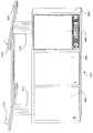
도 1을 다시 참조하여, 본 발명의 적어도 몇몇 실시예들에서, 각각의 슬래브 프리젠테이션 유니트들(22a 및 22b)은 유사한 구성 및 유사한 동작을 가지며, 따라서 본 설명을 간략화하기 위해, 단지 유니트(22a) 만이 상세하게 설명될 것이다. 도 4 및 5를 참조하여, 슬래브 프리젠테이션 유니트(22a)는 풀-아웃 롤러 윈도우 쉐이드 스타일 유니트이며, 하우징 어셈블리(100, 이하 하우징(100)), 트랜시버(34a), 회전식 및 비회전식 프리젠테이션 스크린(38a), 제 1 및 제 2 마운팅 멤버들 또는 후크들(102 및 104), 각각 프로세서(110), 모니터(112), 전력이 제공되는 스크린 스핀들(114), 본 발명의 예에서 프린터(116)의 형태를 지니는 슬래브 프리젠터/프린트 어플리케이터, 소거장치(118) 및 메모리(119)를 포함한다. 하우징(100)은 일반적으로 각각 상부 및 하부 벽들(107 및 109) 사이 및 각각 전방 및 후방 벽들(111 및 113) 사이에 구멍(105)을 형성하는 단단한 박스 형태의 어셈플리이다. 전방 벽(111) 및 후방 벽(113)은 각각 상반되게 직면하는 전면 및 후면들(101 및 103)을 형성한다. 하부 벽(109)은 스크린(38a)의 더 낮은 단부가 연장하는 하우징(100)의 길이를 따라 슬릿 또는 개구부(122)를 형성한다. 마운팅 멤버들(102 및 104)의 각각은 마스터 유니트 하우징(52)에 고정된 마운팅 멤버들(72 및 74)과 유사하게 하우징(100)의 후면(113)으로부터 후방으로 연장하고 하우징(100)의 반대 단부들로부터 연장하도록 고정된다. 각각의 멤버들(102 및 1104)의 원심 단부들은 레일(40)의 폭 크기 W1와 유사한 채널 크기 R2를 가지고 멤버(102)가 채널(117)을 형성하고 멤버(104)가 채널(115)을 형성하도록 아래쪽으로 연장한다. 따라서, 메인 유니트(28)의 경우에서와 같이, 슬래브 유니트(22a)는 멤버들(102 및 104)을 레일(40) 위에 배치함으로써 레일(40)에 장착할 수 있고, 따라서 레일(40)은 채널들(115 및 117) 내에서 수신된다.Referring again to FIG. 1, in at least some embodiments of the present invention, eachslab presentation units 22a and 22b have a similar configuration and similar operation, and thus, onlyunit 22a to simplify the present description. ) Will be described in detail. 4 and 5, theslab presentation unit 22a is a pull-out roller window shade style unit, housing assembly 100 (hereafter housing 100),transceiver 34a, rotating and non-rotating presentation screens. 38a, first and second mounting members or hooks 102 and 104,processor 110, monitor 112,screen spindle 114 powered,printer 116 in the example of the present invention. A slab presenter / print applicator, aneraser 118, and amemory 119 in the form of < RTI ID = 0.0 > Thehousing 100 is generally a rigid box-shaped assembly that forms a hole 105 between the upper andlower walls 107 and 109, respectively, and between the front andrear walls 111 and 113, respectively. Thefront wall 111 and therear wall 113 form front andrear surfaces 101 and 103 which face oppositely, respectively. Thebottom wall 109 defines a slit or opening 122 along the length of thehousing 100 through which the lower end of thescreen 38a extends. Each of the mountingmembers 102 and 104 extends rearward from therear side 113 of thehousing 100 and retracts from thehousing 100 similarly to the mountingmembers 72 and 74 secured to themaster unit housing 52. It is fixed to extend from opposite ends. The centrifugal ends of each of themembers 102 and 1104 have a channel size R2 similar to the width size W1 of therail 40 and themember 102 forms thechannel 117 and themember 104 forms thechannel 115. Extend downward to form. Thus, as in the case of themain unit 28, theslab unit 22a can be mounted to therail 40 by placing themembers 102 and 104 over therail 40, so that therail 40 Received inchannels 115 and 117.

트랜시버(34a)는 상부 벽(107)에 장착되고, 그로부터 위쪽으로 연장한다. 스크린(38a)은 본 발명의 적어도 몇몇 실시예들에서 유연하고 회전가능한 일반적으로 직선의 멤버이며, 회전되지 않을 때 개구부(122)를 통해 하우징(100)의 전면(101)과 동일한 방향으로 직면하는 프리젠테이션 표면(48a)을 제공하기 위해 아래로 연장한다. 적어도 몇몇 실시예들에서, 프리젠테이션 표면(48a)은 Mylar(Fupont사에 의해 개발되고 판매되는 폴리에스테르 재료의 상표명)과 같은 기록가능/소거가능 표면 또는 소거 가능한 링크가 프린트되거나 도면으로 표시될 수 있고 이후에 소거될 수 있는 유사 물품이다. 몇몇 경우들에서, 가중 표시되는 바(106)는 스크린(38)이 회전되지 않고 하우징(100) 아래로 연장할 때 스크린(38a)을 실질적으로 편평하게 유지하도록 돕는 스크린(38a)의 원심 하단부에 장착될 수 있다.Thetransceiver 34a is mounted to theupper wall 107 and extends upwards therefrom.Screen 38a is a generally linear member that is flexible and rotatable in at least some embodiments of the invention and faces through theopening 122 in the same direction as thefront face 101 of thehousing 100 when it is not rotated. It extends down to provide apresentation surface 48a. In at least some embodiments, thepresentation surface 48a may be printed or labeled with a recordable / eraseable surface or an erasable link, such as Mylar (trademark of polyester material developed and sold by Fupont). And similar articles that can be erased afterwards. In some cases, theweighted bar 106 is located at the centrifugal bottom of thescreen 38a to help keep thescreen 38a substantially flat when the screen 38 extends below thehousing 100 without being rotated. Can be mounted.

설명되는 실시예에서, 프로세서(110), 모터(112), 스핀들(114), 프린터(116) 및 소거장치(118) 각각은 하우징 구명(105) 내에 장착된다. 프로세서(110)는 그들 구성요소들 각각을 제어하기 위해 모터(112), 프린터(116) 및 소거장치(118)의 각각에 연결된다. 프로세서(110)는 또한 그 내부에 정보를 액세스하기 위해 메모리(119)에 연결되고, 데이터 패킷들을 송수신하기 위해 트랜시버(34a)에 연결된다. 모터(112)는 스핀들(114)의 상부에 부착된 회전식 및 비회전식 슬래브 스크린(38a)을 위해 스핀들(114)에 연결된다.In the described embodiment, each of theprocessor 110, themotor 112, thespindle 114, theprinter 116, and the erasingdevice 118 are mounted within the housing life 105.Processor 110 is coupled to each ofmotor 112,printer 116 and erasingdevice 118 to control each of those components.Processor 110 is also coupled tomemory 119 to access information therein and totransceiver 34a for transmitting and receiving data packets.Motor 112 is connected to spindle 114 for a rotary andnon-rotating slab screen 38a attached to the top ofspindle 114.

프로세서(110)는 이미지가 마스터 유니트(28)로부터 슬래브 유니트(22a)로 플립될 때 프리젠테이션 표면(48a) 상에 이미지를 스크린(38a)이 회전되지 않는 것으로 프린트하거나 선택적으로 스핀들을 통해 스크린(38a)을 위아래로 이동시키면서 표면(48a)에 인접하게 하나 또는 그 이상의 프린터 헤드들을 이동시킴으로써 프린터(116)를 제어한다. 임의의 경우에, 프로세서(110)는 마스터 유니트(28)로부터 유니트(22a)로 플립된 이미지의 해석(rendition)을 제공하기 위해 프린터(116)를 제어한다. 몇몇 경우들에서 해석은 컬러가 될 수 있는 반면, 다른 경우들에서 흑백이 될 수 있다. 다른 경우들에서, 사용자는 컬러 또는 흑백으로 프린트하는 옵션을 가질 수 있다.Theprocessor 110 prints the image on thepresentation surface 48a as thescreen 38a is not rotated when the image is flipped from themaster unit 28 to theslab unit 22a or, optionally, through the spindle ( Theprinter 116 is controlled by moving one or more print heads adjacent thesurface 48a while moving 38a) up and down. In any case,processor 110controls printer 116 to provide a translation of an image flipped frommaster unit 28 tounit 22a. In some cases the interpretation may be color, while in other cases it may be black and white. In other cases, the user may have the option of printing in color or black and white.

소거기(118)는 프린터(116)에 의해 프리젠테이션 표면(48a)으로 적용된 잉크를 소거시키도록 프로세서(110)에 의해 제어된다. 이를 위해, 소거기(118)는 스크린 스핀들(114)이 스크린(38a) 위로 회전함에 따라 소거 패드를 표면(48a) 위에 고정하면서 하우징(100)의 길이를 따라 간단히 앞뒤로 이동할 수 있다. 선택적으로, 프로세서(110)는 소거기(118)가 표면(48a)에 다른 정보를 유지하면서 표면(48a)으로부터 특정 정보를 소거하도록 제어할 수 있다. 여기에서, 예를 들어, 시스템 오 퍼레이터가 마스터 유니트(28)를 통해 편집될 슬래브 유니트(22a)로부터의 이미지에 다시 액세스하는 경우에, 만약 편집이 간단히 유니트(280를 통해 이미지의 개별 부분을 소거하고, 이후에 수정된 이미지를 다시 유니트(22a)로 다시 플립하는 것을 포함하는 경우에, 수정된 이미지는 표면(48a)으로부터 적절한 정보를 소거하고, 스크린(38a)의 회전을 중단함으로써 수정된 이미지가 표면(48a)을 통해 관찰될 수 있도록 함으로써 유니트(22a)에 의해 표시될 수 있다.Theeraser 118 is controlled by theprocessor 110 to erase the ink applied by theprinter 116 to thepresentation surface 48a. To this end, theeraser 118 can simply move back and forth along the length of thehousing 100 while securing the erase pad over thesurface 48a as thescreen spindle 114 rotates over thescreen 38a. Optionally, theprocessor 110 may control theeraser 118 to erase certain information from thesurface 48a while maintaining other information on thesurface 48a. Here, for example, if the system operator accesses an image from theslab unit 22a to be edited via themaster unit 28 again, if editing is simply a separate part of the image via theunit 280 In the case of erasing and subsequently flipping the modified image back to theunit 22a, the modified image is modified by erasing the appropriate information from thesurface 48a and stopping the rotation of thescreen 38a. The image can be displayed by theunit 22a by allowing the image to be viewed through thesurface 48a.

따라서, 도 1 내지 5에 개시된 실시예에서, 운영자가 마스터 스크린 디스플레이(48) 상의 이미지가 유니트(22a)에 플립될 것이라고 표시할 때, 이미지 데이터 패킷은 트랜시버(22)를 통해 프로세서(110)에 전송되고, 프로세서(110)가 스크린(38a)의 회전을 동시에 중지하도록 모터(12)와 프린터(116)를 제어하고, 잉크를 표면(48a)에 적용시킴으로써 표면(48a) 상에 플립된 이미지를 형성한 후에 트랜시버(34a)로 전송된다. 이미지가 표면(48a) 상에 형성된 후에, 만약 시스템 오퍼레이터가 또다른 이미지를 유니트(22a)로 플립하면, 프로세서(110)는 먼저 스크린(38a)을 회전하기 위해 모터(112) 및 소거기(118)를 제어하면서 그 위에 프린트된 잉크를 소거한다. 표면(48a)이 깨끗해진 후에, 프로세서(110)는 다음에 모터(112)와 프린터(116)가 다시 잉크를 표면(48a)에 적용하고, 따라서 새로 플립된 이미지를 시청자가 볼 수 있게 표면(28a)에 제공하도록 제어한다.Thus, in the embodiment disclosed in FIGS. 1-5, when the operator indicates that the image on themaster screen display 48 will be flipped to theunit 22a, the image data packet is sent to theprocessor 110 via thetransceiver 22. Is transmitted, and theprocessor 110 controls themotor 12 and theprinter 116 to stop the rotation of thescreen 38a at the same time, and applies the ink to thesurface 48a to flip the image flipped on thesurface 48a. After forming, it is transmitted to thetransceiver 34a. After the image is formed on thesurface 48a, if the system operator flips another image to theunit 22a, theprocessor 110 first rotates themotor 112 and theeraser 118 to rotate the screen 38a. ) And erase the ink printed on it. After thesurface 48a is cleaned, theprocessor 110 then themotor 112 and theprinter 116 again apply ink to thesurface 48a, thus allowing the viewer to view the newly flipped image. 28a).

슬래브 유니트들(22a 또는 22b) 중 하나가 새로운 이미지를 표면(48a) 상에 형성할 때 현존하는 이미지를 소거하고 잉크를 적용하는데 몇시간(예를 들면, 30초 또는 그 이상)이 걸릴 수 있고, 이미지가 마스터 유니트(28)로부터 플립된 이후에, 디스플레이(48)는 즉시 소거되고 공동 프로세스를 계속하는데 사용될 수 있다. 따라서, 전술된 방식으로 이미지를 생성하는데 있어 지연은 공동의 노력을 지연시키지 않을 것이다.When one of theslab units 22a or 22b forms a new image on thesurface 48a it may take several hours (eg 30 seconds or more) to erase the existing image and apply ink. After the image is flipped from themaster unit 28, thedisplay 48 can be immediately erased and used to continue the collaborative process. Thus, the delay in generating the image in the manner described above will not delay collaborative effort.

도 1을 참조하여, 마스터 디스플레이 스크린(48) 및 이미지를 표시하기 위해 사용되고 회전되지 않는 슬래브 스크린(38a)의 일부분의 크기들은 유사하기 때문에 스크린(38a)으로 플립되고 표시되는 이미지는 디스플레이(48)를 통해 원래 표시되었던 이미지의 스케일과 실질적으로 유사한 스케일을 가지는 것이 인식되어야 한다.Referring to FIG. 1, since the sizes of the portion of themaster display screen 48 and the portion of theslab screen 38a that are used to display the image and not rotated are similar, the image being flipped to thescreen 38a and displayed is displayed on thedisplay 48. It should be appreciated that the scale has a scale substantially similar to that of the image that was originally displayed.

도 1 내지 도 5를 참조하여, 마스터 및 슬래브 유니트들(28 및 22a, 22b, 등등)은 레일(40)로부터 제거할 수 있는 경우에, 전술된 전체 시스템은 하나의 회의실(11)에서 다른 회의실로 용이하게 전달될 수 있고, 유니트들의 후면들로부터 연장하는 장착 부재들을 레일(40)과 유사한 다른 회의실 내의 레일을 통해 배치함으로써 형성될 있다. 전달 동안, 슬래브 유니트들의 스크린들(예를 들면, 38a)은 보호 및 밀집된 구성을 제공하기 위해 완전히 감아 올려질 수 있다.With reference to FIGS. 1 to 5, where the master andslab units 28 and 22a, 22b, etc. can be removed from therail 40, the entire system described above is oneconference room 11 to another conference room. Can be easily delivered and formed by placing mounting members extending from the backs of the units through rails in other meeting rooms similar torails 40. During delivery, the screens of the slab units (eg 38a) can be completely rolled up to provide a protective and dense configuration.

도 6을 참조하여, 슬래브 프리젠테이션 유니트(120)의 제 2 실시예는 탑 헤더(122), 하우징(124), 트랜시버(130), 스크린(126) 및 제 1 및 제 2 장착 부재들(132, 134)을 각각 포함하여 도시된다. 장착 부재들(132, 134)은 전술된 장착 부재들(102, 104)의 구성 및 동작과 유사하며, 따라서 상세히 설명되지 않는다. 여기에서, 부재들(132, 134)이 장착 유니트(120)를 위한 헤더(122)의 후면으로부터 전술된 레일(40)과 같은 레일로 연장하는 것을 설명하는 것으로 충분하다.Referring to FIG. 6, a second embodiment of theslab presentation unit 120 includes atop header 122, ahousing 124, atransceiver 130, ascreen 126, and first and second mountingmembers 132. 134, respectively. The mountingmembers 132, 134 are similar to the construction and operation of the mountingmembers 102, 104 described above, and thus will not be described in detail. Here, it is sufficient to explain that themembers 132, 134 extend from the rear of theheader 122 for the mountingunit 120 to the same rail as therail 40 described above.

상기 제 2 실시예에서, 스크린(126)은 헤더(122)의 아랫면에 견고하게 부착되며, 아래쪽 하우징은 스크린(126)의 원심 하단부가 연장하고 도 5와 관련하여 전술된 스핀들(114)과 유사한 스크린 스핀들이 장착되는 개구부(비도시)를 형성한다. 부가적으로, 상기 실시예에서, 도 5와 관련하여 전술된 프로세서(110), 모터(112), 프린터(116), 메모리(1119) 및 소거기(118)는 하우징(124) 내에 장착되며, 트랜시버(130)는 하우징(124)으로부터 상향 연장한다. 여기에서, 이미가 마스터 유니트(28)로부터 슬래브 유니트(120)로 플립될 때, 전송된 이미지 데이터 패킷은 트랜시버(130)를 통해 수신되고, 하우징(124) 내의 프로세서는 하우징(124)이 헤더(122) 밑으로 내려감에 따라(화살표(128) 도시) 그 위에 플립된 이미지를 형성할 때 그 내부의 모터 프린터가 스크린(126)을 감지 않고 잉크를 표면(126)에 적용하도록 동시에 제어한다. 상기 경우에 장점은 이미지가 상부에서 하부로 프린트될 수 있다는 점이다. 유사하게, 표면(126) 상의 이미지가 소거될 때, 하우징(124) 내부의 하우징(124) 내의 모터와 소거기가 스크린(126)을 위로 감아 올리고 표면(126)으로부터 잉크를 소거하도록 동시에 제어한다.In this second embodiment, thescreen 126 is firmly attached to the underside of theheader 122 and the lower housing extends from the centrifugal lower end of thescreen 126 and is similar to thespindle 114 described above with respect to FIG. 5. It forms an opening (not shown) in which the screen spindle is mounted. Additionally, in this embodiment, theprocessor 110,motor 112,printer 116, memory 1119, anderaser 118 described above with respect to FIG. 5 are mounted within thehousing 124, Thetransceiver 130 extends upwardly from thehousing 124. Here, when the image is flipped from themaster unit 28 to theslab unit 120, the transmitted image data packet is received through thetransceiver 130, and the processor in thehousing 124 causes thehousing 124 to have a header ( 122) As it descends (shown by arrow 128), when forming an image flipped over it, the motor printer therein simultaneously controls the application of ink to thesurface 126 without sensing thescreen 126. The advantage in this case is that the image can be printed from top to bottom. Similarly, when the image on thesurface 126 is erased, the motor and eraser in thehousing 124 inside thehousing 124 simultaneously control to wind up thescreen 126 and erase ink from thesurface 126. .

도 7, 8, 9를 참조하여, 도 5의 슬래브 유니트와 유사한 슬래브 유니트들의 3개의 추가 실시예들(171, 173, 175)이 설명된다. 도 7 내지 9에서, 슬레이 유니트들 각각은 도 5와 관련하여 전술된 것과 유사한 프로세서(110), 모터 또는 임의의 타입의 구동장치(112), 프린터(118), 소거기(116), 메모리(비도시), 장착 부재(예를 들면, 104), 및 트랜시버(34a)를 포함하며, 따라서 본 설명을 간략화하 위해, 상기 구성요소들은 여기에서 다시 설명되지는 않는다. 도 7, 8, 9의 실시예들 및 도 5의 실시예 간의 주요 차이는 프리젠테이션 스크린들이 연장되고 축소되는 방식이다.7, 8, 9, threeadditional embodiments 171, 173, 175 of slab units similar to the slab unit of FIG. 5 are described. In Figures 7 to 9, each of the slave units may include aprocessor 110, a motor or any type ofdrive 112,printer 118,eraser 116, memory (similar to that described above with respect to Figure 5). Not shown), mounting member (eg, 104), andtransceiver 34a, and therefore, for simplicity of the description, the components are not described herein again. The main difference between the embodiments of FIGS. 7, 8, 9 and 5 is in the manner in which the presentation screens are extended and reduced.

도 7의 실시예는 일반적으로 풀-아웃 순환 루프형 유니트이며, 전원 공급형 스핀들(151)과 자유 회전 스핀들(148) 모두를 포함한다. 전원 공급형 스핀들(151)은 프로세서(110)의 제어하에 모터(112)에 의해 구동된다. 도 7에서 스크린(144)은 하우징(100) 내의 전원 공급형 스핀들(151) 주위를 둘러싸고, 아래로 연장하여 하우징(100) 아래의 자유 회전 스핀들(148)을 주위를 둘러싸는 연속하는 벨트 또는 루프형 스크린이며, 따라서 스크린 전면 세그먼트는 프리젠테이션 전면(155)을 형성하고, 스크린 후면 세그먼트는 표면(155)의 방향과 상반되는 방향에서 직면하는 후면(159)을 형성한다. 적어도 몇몇 실시예에서, 하우징(100)은 스크린(145)이 그를 통해 통과하도록 하우징(100)의 전체 길이를 따라 연장하는 개구부들(140, 142)과 같은 2개의 슬릿을 형성한다.The embodiment of FIG. 7 is generally a pull-out circular loop type unit and includes both a powered spindle 151 and a freerotating spindle 148. The powered spindle 151 is driven by themotor 112 under the control of theprocessor 110. In FIG. 7, thescreen 144 surrounds a powered spindle 151 in thehousing 100 and extends downward to form a continuous belt or loop that surrounds the freerotating spindle 148 below thehousing 100. The screen front segment thus forms thepresentation front face 155 and the screen back segment forms theback face 159 facing in a direction opposite to the direction of thesurface 155. In at least some embodiments, thehousing 100 forms two slits, such asopenings 140, 142 that extend along the entire length of thehousing 100 so that the screen 145 passes therethrough.

적어도 몇몇 실시예들에서, 스핀들(151)은 시계 방향 또는 시계 반대 방향으로 전원이 공급될 수 있고, 따라서 스크린(144)은 화살표(146)에 의해 표시되는 것과 같이 위 아래로 이동할 수 있고 자유 회전 스핀들(148)은 화살표(150)에 의해 표시되는 것과 같이 시계 방향 또는 시계 반대 방향으로 회전할 수 있다. 여기에서, 본 발명의 적어도 몇몇 실시예들에서, 이미지가 유니트(171)에 플립될 때, 프로세서(110)는 모터(112) 및 프린터(116)를 동시에 제어하여 잉크를 적용하고 스핀들(151)이 시계 방향으로 회전함에 따라 이미지를 스크린(144)에 형성한다. 이미지가 형성된 후에, 이미지는 하우징(100)가 자유 회전 스핀들(148) 사이의 전 면(155)에서 볼 수 있다. 상기 경우에, 이미지를 소거하기 위해, 스핀들(151)은 시계 반대 방향으로 회전될 수 있고, 소거기(118)는 잉크를 스크린(144)으로부터 제거할 수 있다. 선택적으로, 전면(155)으로부터 이미지를 소거하기 위해, 스핀들(151)은 시계 방향으로 회전될 수 있고, 따라서 이미지는 자유 회전 스핀들(148) 주위를 회전하고, 다시 위로 복귀하고 전원 공급형 스핀들(151) 주위를 회전하여 다시 이전의 소거기(118)로 내려가며, 소거기(118)는 스크린상의 잉크를 소거한다. 도 7에는 도시되지 않는 다른 실시예에서, 소거기(118)는 하우징(100) 내의 스크린(144)의 반대편에 위치될 수 있고, 섹션(155)이 개구부(140)를 통해 위로 이동됨에 따라 스크린(144) 상에 섹션(155)으로서 표시된 이미지들을 소거하도록 사용될 수 있다.In at least some embodiments, the spindle 151 may be powered clockwise or counterclockwise, such that thescreen 144 may move up and down as indicated byarrow 146 and free rotate.Spindle 148 may rotate clockwise or counterclockwise as indicated byarrow 150. Here, in at least some embodiments of the present invention, when the image is flipped onto theunit 171, theprocessor 110 simultaneously controls themotor 112 and theprinter 116 to apply ink and to the spindle 151. As this clockwise rotates, an image is formed on thescreen 144. After the image is formed, the image can be seen on thefront surface 155 between thehousing 100 and the freerotating spindle 148. In this case, to erase the image, the spindle 151 can be rotated counterclockwise, and theeraser 118 can remove ink from thescreen 144. Optionally, to erase the image from thefront surface 155, the spindle 151 can be rotated clockwise, so that the image rotates around the freerotating spindle 148, and returns back up and back to the powered spindle ( 151 rotates around and back to theprevious eraser 118, which erases ink on the screen. In another embodiment, not shown in FIG. 7, theeraser 118 may be positioned opposite thescreen 144 in thehousing 100, with the screen as thesection 155 moves up through theopening 140. It can be used to erase the images marked assection 155 on 144.

도 8을 참조하여, 예시적인 슬래브 프리젠테이션 유니트(173)는 풀-아웃 드롭 루프형 유니트이며, 모두 하우징(100)내에 장착되는 제 2 전원 공급형 스핀들(163) 및 제 2 전원 공급형 스핀들(165) 및 자유 회전 스핀들(167)을 포함하며, 상기 프리젠테이션 스크린(181)의 제 1 및 제 2 단부들은 각각 스핀들(163, 165)에 장착되고 주위에서 회전되며, 스크린(181)의 중앙 부분은 하우징(100) 아래로 내려가는 자유 회전 스핀들(167)을 감싼다. 상기 경우에, 전원 공급형 스핀들(163, 165)은 화살표(146)에 의해 표시되는 것과 같이 스크린(181)의 프리젠테이션 표면(183) 위 아래로 및 화살표(187)에 의해 표시된 것과 같은 방향으로 스핀들(167) 주위를 이동하도록 사용된다. 상기 슬래브 유니트 실시예들에서와 같이, 프린터(116) 및 소거기(118)는 프리젠테이션 표면에 잉크를 적용하거나 그로부터 잉크 를 제거하여 마스터 유니트(28)와의 상호작용에 의해 발생된 이미지 플립핑 작용을 반영하도록 제어될 수 있다.Referring to FIG. 8, the exemplaryslab presentation unit 173 is a pull-out drop loop type unit, both of which have a secondpowered spindle 163 and a second powered spindle (mounted in the housing 100). 165 and a freerotating spindle 167, wherein the first and second ends of thepresentation screen 181 are mounted to and rotated around thespindles 163 and 165, respectively, and the central portion of thescreen 181. Wraps around a freerotating spindle 167 descending below thehousing 100. In this case, thepowered spindles 163, 165 are up and down thepresentation surface 183 of thescreen 181 as indicated byarrow 146 and in the same direction as indicated byarrow 187. It is used to move around thespindle 167. As in the slab unit embodiments, theprinter 116 and theeraser 118 act as image flipping generated by interaction with themaster unit 28 by applying ink to or removing ink from the presentation surface. It can be controlled to reflect.

도 9를 참조하여, 유니트(175)는 도 5, 7, 8과 관련하여 전술된 유니트들과 유사한 풀-아웃 아코디언형 유니트이며, 이는 스핀들이 감고 푸는 어셈블리(274)로 대체되고, 감을 수 있는 스크린 부재 대신에 스크린이 연장되는 수평 스크린 멤버들을 포함하는 세분화된 아코디언형 스크린(172)이라는 사실을 제외하고는 동일하며, 상기 멤버들은 번호(189)에 의해 총체적으로 식별되며, 수평으로 연장되는 에지들을 따라 결합된다. 여기서, 유도기(motivator)(112)는 프로세서(110)에 의해 제어되어 프린터(116)에 인접하게 스크린(172)을 풀고, 화살표 170으로 나타낸 것처럼 이레이저(118)에 인접하게 스크린(172)을 감는다.With reference to FIG. 9,unit 175 is a pull-out accordion type unit similar to the units described above with respect to FIGS. 5, 7 and 8, which is replaced by anassembly 274 which the spindle winds and unwinds, The same is true except for the fact that it is a subdivided accordion-like screen 172 that includes horizontal screen members on which the screen extends instead of the screen member, the members being collectively identified bynumber 189 and extending horizontally. Combined along them. Here, themotivator 112 is controlled by theprocessor 110 to release thescreen 172 adjacent to theprinter 116, and to move thescreen 172 adjacent to theerasure 118 as indicated byarrow 170. Wind up

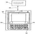
도 1, 10a 및 10b를 참조하면, 예시적인 HHD 인터페잇 유니트(200)은 프로세서(203), 디스플레이(204), 키보드(209) 및 트랜스시버(211)를 포함하는 다른 유니트 컴포넌트들을 지지 및 보호하는 일반적으로 직선형 강성(rigid) 플라스틱 또는 금속 하우징(199)을 포함한다. 프로세서(203)는 이로부터 정보를 수신하거나 적절한 곳에 정보를 제공하도록 각각의 트랜스시버(211), 스크린(204), 메모리(207) 및 키보드(209)에 접속된다. 프로세서(203)는 메모리(207)에 저장된 다양한 프로그램들을 실행한다. 또한, 본 발명의 적어도 몇몇 실시예들에서, 프로세서(203)는 컨퍼런스 룸(11) 내부에 또는 컨퍼런스 룸(11)에 인접하게 장착된 액세스 지점들을 갖는 무선 통신을 통해, 종래의 컴퓨터 네트워크(예, 로컬 영역 네트워크, 광역 네트워크, 인터넷 등)에 액세스할 수 있다. 액세스 지점들을 통한 유니트(200)과 같 은 무선 장치들과 네트워크 서버 간의 통신은 무선 통신 기술분야에 공지되어 있으므로, 이러한 설명을 간략하는 점에서 본 발명에서 상세히 기술되지 않는다.1, 10A and 10B, an exemplaryHHD interface unit 200 supports and protects other unit components including aprocessor 203, adisplay 204, akeyboard 209 and atransceiver 211. It generally comprises a straight rigid plastic ormetal housing 199.Processor 203 is connected to eachtransceiver 211,screen 204,memory 207, andkeyboard 209 to receive information from or provide information where appropriate. Theprocessor 203 executes various programs stored in thememory 207. In addition, in at least some embodiments of the present invention, theprocessor 203 may, via wireless communication with access points mounted within or adjacent to theconference room 11, to provide a conventional computer network (eg, , Local area networks, wide area networks, the Internet, etc.). Communication between network devices and wireless devices, such asunit 200 via access points, is well known in the wireless communication art, and therefore this description is not described in detail herein in the interest of simplicity.

키보드(209)는 도 2에 관해 전술한 키보드 키들과 유사한 하드웨어 키들을 포함한다. 구체적으로는, 기계적 키들(208, 210, 216, 220)은 전술한 키들(56, 60, 62, 58)과 유사하며, 프리젠테이션을 재개(resume)하고, 프리젠테이션과 연관된 영상들을 저장하며, 슬래브 유니트들에 의해 표시되는 영상들을 복원하여 마스터 유니트(28)에 의해 재-표시될 수 있고, 마스터 유니트(28)으로부터의 영상들을 슬래브 유니트들 중 임의의 하나로 각각 전송하기 위해 사용될 수 있다. 넘버 패드(214)는 도 2와 관련하여 전술한 넘버 패드(67)와 유사한 방식으로 사용된다. 예를 들어, 영상이 전환(flip)되어야 하는 식별자 넘버 "2"와 연관된 슬래브 유니트을 나타내기 위해, 오퍼레이터는 키보드(209)로부터 "2" 키를 선택한 후 전송 키(220)를 선택한다.Thekeyboard 209 includes hardware keys similar to the keyboard keys described above with respect to FIG. 2. Specifically, themechanical keys 208, 210, 216, 220 are similar to thekeys 56, 60, 62, 58 described above, resume a presentation, store images associated with the presentation, The images displayed by the slab units can be restored and re-displayed by themaster unit 28 and used to transfer the images from themaster unit 28 to any one of the slab units, respectively. Thenumber pad 214 is used in a similar manner to thenumber pad 67 described above with respect to FIG. For example, to indicate the slab unit associated with the identifier number "2" to which the image should flip, the operator selects the "2" key from thekeyboard 209 and then selects the transmit key 220.

좌측 화살표 키(222)는 그 라벨이 암시하는 것처럼, 마스터 유니트(28)을 통해 현재 표시되는 영상이 마스터 유니트(28)의 좌측으로 슬래브 유니트에 전송되어야 함을 나타내는 전송 좌측 키이다. 유사하게, 우측 화살표 키(228)는 마스터 유니트(28)에 의해 현재 디스플레이되는 영상이 마스터 유니트(28)의우측으로 슬래브 유니트에 전송되어야 함을 나타내는 전송 우측 키이다. 우측 지향되는 화살표 키(223)는 마스터 유니트(28)의 좌측으로 슬래브 유니트상에 현재 표시되는 영상이 마스터 유니트으로 복원되고 이에 따라 디스플레이되어야 함을 나타내는 좌측 복원 키이다. 유사하게, 좌측 지향되는 화살표 키(226)는 마스터 유니트(28)의 우측으 로 슬래브 유니트에 의해 현재 표시되는 영상이 마스터 유니트(28)에 의해 복원 및 디스플레이되어야 함을 나타내는 우측 복원 키이다.Theleft arrow key 222 is a transmission left key indicating that the image currently displayed through themaster unit 28 should be transmitted to the slab unit to the left of themaster unit 28, as the label suggests. Similarly,right arrow key 228 is a transmit right key indicating that the image currently displayed bymaster unit 28 should be sent to the slab unit to the right ofmaster unit 28. Thearrow key 223 directed to the right is a left recovery key indicating that the image currently displayed on the slab unit to the left of themaster unit 28 should be restored to the master unit and thus displayed. Similarly, thearrow key 226 directed to the left is the right recovery key indicating that the image currently displayed by the slab unit to the right of themaster unit 28 should be restored and displayed by themaster unit 28.

전술한 키들과 더불어, 엔터 키(212)는 다른 키보드를 통해 기입된 정보가 동작되어야 함을 나타내는데 사용될 수 있는 유니트(200)을 통해 제공된다. 예를 들어, 프리젠테이션이 재개되어야 하고 특정한 7개 디지트 넘버 코드가 이전에 저장된 특정 영상-유니트 세트에 액세스하도록 기입되어야 하는 경우들에서, 재개 버튼(208)이 선택된 이후, 프로세서(203)는 디스플레이(204)를 통해 세션 식별 넘버 필드를 표시할 수 있고, 여기서 7개 넘버들의 특정 시퀀스는 영상-유니트 세트에 해당하는 영상들에 액세스하여 프리젠테이션 유니트들을 통해 영상들을 표시하기 위해 기입되어야 한다. 본 발명의 적어도 몇몇 실시예들에서, 유니트(200)은 전형적으로 컴퓨터 키보드상에 있는 글자들, 넘버들, 및 기능 키들을 포함하는 풀 키보드 컴플리먼트(compliment)를 포함할 수 있고, 이에 따라 유니트(200)은 다양한 소프트웨어 애플리케이션들(예, 파워포인트, 스프레드시트 애플리케이션들, 워드 프로세서 애플리케이션들 등)과 상호작용하도록 최종 랩탑 컴퓨터로서 효과적으로 사용될 수 있다.In addition to the above-described keys, theenter key 212 is provided through theunit 200, which can be used to indicate that information entered via another keyboard should be operated. For example, in cases where a presentation must be resumed and a specific seven digit number code must be written to access a particular stored image-unit set, theprocessor 203 displays after theresume button 208 is selected. 204 may indicate the session identification number field, where a particular sequence of seven numbers should be written to access the images corresponding to the image-unit set and display the images through the presentation units. In at least some embodiments of the invention,unit 200 may comprise a full keyboard compliment, which typically includes letters, numbers, and function keys on a computer keyboard, and thusUnit 200 may be effectively used as a final laptop computer to interact with various software applications (eg, PowerPoint, spreadsheet applications, word processor applications, etc.).

도 1 및 도 10a를 참조하면, 적어도 몇몇 실시예들에서, 스크린(204)은 소프트웨어 애플리케이션들에 상응하는 영상들, 스타일러스(202) 또는 다른 유사한 타입들의 인터페이스 툴들을 통해 스크린(204)에 제공되는 정보에 상응하는 영상들, 및 적어도 몇몇 경우들에서, 소프트웨어 생성된 영상들과 제공된 정보를 조합한 영상들을 포함하는, 임의의 타입의 시각적 영상을 가상으로 디스플레이하는데 사용될 수 있는 완전 기능성 터치 감응성 평판 디스플레이 스크린이다. 따라서, 예를 들어, 파워포인트 슬라이드가 디스플레이(204)상에 표시될 때, 적어도 몇몇 경우들에서, 시스템 오퍼레이터는 프로세서(203)에 의해 추적되고 이에 응답하여 프로세서(203)가 디스플레이(204)상의 영상을 변경하여 마크가 재표시되도록, 디스플레이(204)상에 마크(예, 도 10a의 229)를 형성하기 위해 스타일러스(202)를 이용할 수 있다. 여기서, 마크는 실제 잉크가 스크린(204)의 표면에 인가되지 않는다는 사실에도 불구하고 마크가 디스플레이(204)상에 보여지기 때문에, 가상 잉크 마크로서 지칭된다.1 and 10A, in at least some embodiments, thescreen 204 is provided to thescreen 204 via images,stylus 202, or other similar types of interface tools corresponding to software applications. Fully functional touch sensitive flat panel display that can be used to virtually display any type of visual image, including images corresponding to the information, and in at least some cases, software generated images and images combined with the provided information. It is a screen. Thus, for example, when a PowerPoint slide is displayed ondisplay 204, in at least some cases, the system operator is tracked byprocessor 203 and inresponse processor 203 is ondisplay 204. Thestylus 202 may be used to form a mark (eg, 229 of FIG. 10A) on thedisplay 204 so that the mark is re-displayed by changing the image. Here, the mark is referred to as a virtual ink mark because the mark is shown on thedisplay 204 despite the fact that no actual ink is applied to the surface of thescreen 204.

중요한 것은, 본 발명의 일 실시예에 따라, 제어 인터페이스(200)의 디스플레이(204)를 통해 표시되는 정보가 유니트(28)의 마스터 디스플레이(48)상에 즉시 업데이트된다는 것이다. 따라서, 시스템 오퍼레이터가 HHD(200)를 이용할 때 컨퍼런스 룸(11) 내부의 임의의 곳에 있으면서, 오퍼레이터는 실시간으로 및 공동 플립 차트형 방식으로 디스플레이(48)상에 디스플레이되는 영상을 수정하기 위해 HHD(200)를 사용할 수 있다. 디스플레이(48)상의 영상이 종료된 이후 및 오퍼레이터가 유니트(28)으로부터의 영상을 도 1의 슬래브 유니트들 중 하나(22a 또는 22b)로 전환하길 원할 때, 오퍼레이터는 HHD(200)를 사용하여 영상을 적절한 슬래브 유니트에 플립한다. 예를 들어, 도 1에 도시된 예에서, 마스터 유니트(28)으로부터의 영상을 슬래브 유니트(22a)으로 전환하기 위해, 오퍼레이터는 HHD(200)상의 "1" 키를 선택한 후 전송 키(220)를 선택한다. 전송 키(220)가 선택된 이후, 프로세서(203)는 선택된 슬래브 유니트으로 영상 전환을 명령하고 마스터 유니트 네트워 크 어드레스를 포함하는, 전환 명령 데이터 패킷을 형성하고, 트랜스시버들(211, 20)를 통해 전환 명령 데이터 패킷을 프로세서(80)(도 3을 다시 참조)로 송신한다. 전환 명령 수신에 응답하여, 프로세서(80)는 현재 디스플레이되는 영상을 포함하는 영상 데이터 패킷을 형성하고, 영상 데이터 패킷을 HHD(200)를 통해 선택된 슬래브 유니트으로 송신한다.Importantly, according to one embodiment of the present invention, the information displayed via thedisplay 204 of thecontrol interface 200 is immediately updated on themaster display 48 of theunit 28. Thus, while the system operator is anywhere inside theconference room 11 when using theHHD 200, the operator can modify the image displayed on thedisplay 48 in real time and in a collaborative flip chart manner. 200) can be used. After the image on thedisplay 48 is finished and when the operator wants to switch the image from theunit 28 to one of theslab units 22a or 22b of FIG. 1, the operator uses theHHD 200 to display the image. Flip on the appropriate slab unit. For example, in the example shown in FIG. 1, in order to convert the image from themaster unit 28 to theslab unit 22a, the operator selects the "1" key on theHHD 200 and then thetransmission key 220. Select. After the transmit key 220 is selected, theprocessor 203 instructs the switch of the image to the selected slab unit and forms a switch instruction data packet containing the master unit network address, and switches through thetransceivers 211 and 20. The command data packet is sent to the processor 80 (see FIG. 3 again). In response to receiving the switch command, theprocessor 80 forms an image data packet including the image currently displayed, and transmits the image data packet to the selected slab unit through theHHD 200.

도 10a, 도 10b 및 도 1을 참조하면, 유니트(200)은 독립형 랩탑 컴퓨터일 수 있고, 마스터 유니트(28)이 간단히 출력 및 입력 장치인 최종 데이터 처리 플랫폼을 제공할 수 있다. 여기서, 예를 들어, 디스플레이(20)와의 상호작용을 추적하기 위한 프로그램들이 유니트(200)에 의해 실행될 수 있고, 유니트(200)은 마스터 유니트 프로세서(80)에 디스플레이 구동 데이터를 간단히 제공할 수 있다.10A, 10B, and 1, theunit 200 may be a stand-alone laptop computer, and themaster unit 28 may simply provide a final data processing platform that is an output and input device. Here, for example, programs for tracking interaction with thedisplay 20 may be executed by theunit 200, which may simply provide display drive data to themaster unit processor 80. .

또한, 이 경우, 유니트(200)은 영상 프리젠테이션을 최종적으로 구성할 수 있고, 마스터 유니트(28)은 전환 및 복원 프로세스들을 수행하지 않을 수 있다. 여기서, 예를 들어, 유니트(200)은 마스터 및 슬래브 유니트들에 의해 디스플레이되는 영상들을 포함하는 모든 영상들을 저장할 수 있다. 프리젠터(presenter)가 마스터 유니트(28)을 통해 마스터 영상이 슬래브 유니트으로 전환되어야 함을 나타낼 때, 지정된 슬래브 유니트으로 마스터 영상의 전송을 통해 전환이 교번으로 발생하도록 하는 명령이 유니트(200)에 의해 수신될 수 있다. 또한, 여기서, 유니트(200)은 전환된 영상을 소거하기 위해 마스터 유니트으로 명령을 자동으로 송신할 수도 있다. 또한, 복원 명령들은 마스터 프로세서(80)를 통한 것과 반대로 유니트(200)을 통해 수행된다.In this case, theunit 200 may finally configure the image presentation, and themaster unit 28 may not perform the conversion and restoration processes. Here, for example, theunit 200 may store all images including images displayed by the master and slab units. When the presenter indicates that the master image should be switched to the slab unit via themaster unit 28, a command is issued by theunit 200 to cause the switching to take place alternately by sending the master image to the designated slab unit. Can be received. In addition, theunit 200 may automatically transmit a command to the master unit to erase the converted image. In addition, the restore instructions are performed via theunit 200 as opposed to via themaster processor 80.

도 11을 참조하면, 본 발명의 적어도 몇몇 실시예들에 따른 예시적인 제 2 시스템(230)이 도시된다. 시스템(230)은 도 1과 관련하여 전술한 컨퍼런스 룸(11)과 같은 컨퍼런스 룸의 범주로 도시되고, 여기서 프리젠테이션 유니트들(48, 232)은 청중에 의해 연관된 프리젠테이션 표면들의 용이한 뷰를 위해 컨퍼런스 룸 내의 레일(40)상에 장착된다. 여기서, 마스터 유니트(28)은 도 1과 관련하여 전술한 마스터 유니트(28)과 거의 차이점들이 없이 유사하다. 차이점들과 관련하여, 도 3을 다시 참조하면, 도 11의 실시예의 마스터 유니트 프로세서(80)는 도 1과 관련하여 전술한 프로세서와 다소 상이하게 프로그래밍된다. 보다 구체적으로는, 시스템(230)에 단지 하나의 슬래브 유니트(232)이 있기 때문에, 프로세서(80)는 전송 명령들이 수신될 때 모든 영상들을 단일 슬래브 유니트(232)으로 전환하도록 프로그래밍된다.Referring to FIG. 11, an exemplarysecond system 230 is shown in accordance with at least some embodiments of the present invention.System 230 is shown in the category of a conference room, such asconference room 11 described above with respect to FIG. 1, wherepresentation units 48, 232 provide an easy view of associated presentation surfaces by an audience. To rail 40 in the conference room. Here, themaster unit 28 is similar to themaster unit 28 described above in connection with FIG. 1 with almost no differences. Regarding the differences, referring again to FIG. 3, themaster unit processor 80 of the embodiment of FIG. 11 is programmed somewhat differently than the processor described above with respect to FIG. 1. More specifically, because there is only oneslab unit 232 in thesystem 230, theprocessor 80 is programmed to convert all images to asingle slab unit 232 when transmit commands are received.

둘째, 영상을 슬래브 유니트(232)으로 전환하기 이전에, 프로세서(80)는 영상 식별자 넘버를 전환된 영상에 부가하도록 프로그래밍되고, 본 예에서, 상기 영상 식별자 넘버는 상부 좌측 코너의 전환된 영상에 부가된다. 예를 들어, 도 11에서, 영상 식별자 넘버 "6" 및 "7"은 각각 표면들(250, 248)상에 표시되는 영상들과 연관되고, 이에 따라 식별자 넘버들(6, 7)은 각각의 영상이 순차적으로 고유하게 식별될 수 있도록 각각의 영상들에 부가되었다.Second, prior to converting the image to theslab unit 232, theprocessor 80 is programmed to add an image identifier number to the converted image, and in this example, the image identifier number is assigned to the switched image in the upper left corner. Is added. For example, in FIG. 11, image identifier numbers “6” and “7” are associated with images displayed onsurfaces 250 and 248, respectively, so thatidentifier numbers 6 and 7 are each unique. Images were added to each of the images so that they could be uniquely identified sequentially.

셋째, 영상을 슬래브 유니트(232)으로 전환하기 이전에, 프로세서(80)는 후속적인 액세스를 위해 마스터 유니트 메모리(88)의 영상 식별자 넘버 및 영상을 상관시켜서 저장한다. 도 11에 도시된 상기 예에서, 마스터 유니트 프로세서(80)(도 3을 다시 참조)는 식별자 넘버 6을 갖는 표면(250)상의 영상을 저장하고, 각각의 그러한 영상들이 슬래브 유니트(232)으로 전환될 때, 식별자 넘버 7을 가진 표면(248)상의 영상을 유사하게 저장한다.Third, prior to converting the image to theslab unit 232, theprocessor 80 correlates and stores the image identifier number of themaster unit memory 88 and the image for subsequent access. In the example shown in FIG. 11, master unit processor 80 (see FIG. 3 again) stores an image onsurface 250 withidentifier number 6, and each such image is converted toslab unit 232. The image on thesurface 248 withidentifier number 7 is similarly stored.

도 11을 참조하면, 슬래브 프리젠테이션 유니트(232)은 도 5에 도시된 컴포넌트들과 유사한 컴포넌트들의 세트 또는 컴포넌트들의 서브세트를 포함하는 대형 프린터 또는 플로터(plotter)이다. 따라서, 유니트(232)은 프로세서(336), 모터(338), 프린터(340)와 대형 페이퍼 롤(342), 및 트랜스시버(240)를 포함한다. 유니트(232)의 경우, 프로세서(336)는 모터(338), 트랜스시버(240) 및 프린터(340)에 접속되고, 영상이 유니트(232)으로 전환될 때, 프로세서(336)는 모터(338)와 프린터(340)를 동시에 제어하여, 롤의 펼쳐진(unrolled) 부분이 하향하게 떨어짐에 따라 그 전단 표면(250)에 잉크를 도포하면서 페이퍼 롤의 일부분을 펼친다. 영상을 표면(250)에 제공하는 것과 더불어, 프린터(340)는 영상의 상부 좌측 코너에 영상 식별자 넘버(예, 도 11의 "6")를 제공한다.Referring to FIG. 11, theslab presentation unit 232 is a large printer or plotter that includes a set or subset of components similar to the components shown in FIG. 5. Thus, theunit 232 includes aprocessor 336, amotor 338, aprinter 340 and alarge paper roll 342, and atransceiver 240. In the case of theunit 232, theprocessor 336 is connected to themotor 338, thetransceiver 240 and theprinter 340, and when the image is converted to theunit 232, theprocessor 336 is themotor 338 Andprinter 340 are simultaneously controlled to unfold a portion of the paper roll while applying the ink to itsfront surface 250 as the unrolled portion of the roll falls downward. In addition to providing an image to surface 250,printer 340 also provides an image identifier number (eg, “6” in FIG. 11) in the upper left corner of the image.

영상이 프린팅된 이후, 유니트(232)에서 톤 오프(torn off)되었던 롤의 부분은 감기고 연속적인 뷰를 위해 유니트(232)에 인접하게 배치(post)될 수 있다. 이에 따라, 적어도 몇몇 실시예들에서, 레일(40)은 택들(tacks)이 이를 따라 톤 시트(torn sheet)들을 배치하는데 사용될 수 있도록 코르크판(corkboard) 전단 표면을 포함할 수 있다. 도 11에서, 식별자 넘버로서 넘버 "7"을 갖는 예시적인 톤 시트(234)는 유니트(232)에 인접한 레일(40)에 배치되는 것으로서 도시된다. 시트들이 깨끗한 방식으로 톤 오프될 수 있도록, 페이퍼 롤의 길이를 따라 이격된 위치들 에 천공된 라인들이 제공될 수 있다.After the image is printed, the portion of the roll that has been toned off inunit 232 can be rolled up and post adjacent tounit 232 for continuous viewing. Accordingly, in at least some embodiments,rail 40 may include a corkboard shear surface such that tacks can be used to place ton sheets along it. In FIG. 11, anexemplary tone sheet 234 having the number “7” as the identifier number is shown as being disposed on therail 40 adjacent to theunit 232. Perforated lines can be provided at spaced locations along the length of the paper roll so that the sheets can be toned off in a clean manner.

도 11에 도시된 실시예에서, 도 2 및 도 11을 참조로, 마스터 유니트(28)을 통해 슬래브 유니트(232)에 의해 프린팅된 영상들 중 하나를 재표시하기 위해, 시스템 오퍼레이터는 재표시될 영상과 연관된 넘버를 선택하도록 넘버 패드(67)를 사용하고, 그 다음 복원 키(62)를 선택한다. 예를 들어, 도 11의 시트(234)상에 영상을 재표시하기 위해, 오퍼레이터는 넘버 "7" 및 복원 키(62)를 선택한다. 키(62)가 선택된 이후, 도 3을 다시 한번 참조하면, 마스터 유니트 프로세서(80)는 영상 식별자 넘버 "7"에 상응하는 메모리(88)에 저장된 영상에 액세스하고, 디스플레이(48)를 통해 그 영상을 재표시한다. 영상이 재표시되면, 영상이 수정된 다음, 프린팅 및 포스팅을 위해 슬래브 유니트(232)으로 재-전환될 수 있다.In the embodiment shown in FIG. 11, with reference to FIGS. 2 and 11, in order to re-display one of the images printed by theslab unit 232 via themaster unit 28, the system operator may be re-displayed. Usenumber pad 67 to select the number associated with the image, and then selectreconstruction key 62. For example, to redisplay the image on thesheet 234 of FIG. 11, the operator selects the number "7" and theretrieval key 62. After the key 62 has been selected, referring again to FIG. 3, themaster unit processor 80 accesses the image stored in thememory 88 corresponding to the image identifier number " 7 " Redisplay the image. If the image is redisplayed, the image can be modified and then re-switched to theslab unit 232 for printing and posting.

도 12를 참조하면, 본 발명에 따른 또 하나의 부가적인 시스템(252)이 도시된다. 여기서, 시스템(251)은 마스터 프리젠테이션 유니트(48)과 제 1 및 제 2 슬래브 유니트(252a, 252b)을 각각 포함한다. 도시된 실시예에서, 마스터 유니트(48)은 슬래브 유니트들(252a, 252b) 사이의 레일(40)에 장착되어, 청중의 시야로부터 볼 때, 유니트(252a)이 마스터 유니트(48)의 좌측에 있고, 유니트(252b)은 마스터 유니트(48)의 우측에 있다.12, another additional system 252 in accordance with the present invention is shown. Here, thesystem 251 includes amaster presentation unit 48 and first andsecond slab units 252a and 252b, respectively. In the illustrated embodiment, themaster unit 48 is mounted to therail 40 between theslab units 252a and 252b so that when viewed from the audience's field of view, theunit 252a is on the left side of themaster unit 48. Theunit 252b is on the right side of themaster unit 48.

마스터 유니트(48)은 전술한 마스터 유니트들과 유사하므로, 여기서 상세히 기술되지 않는다. 각각의 슬래브 유니트들(252a, 252b)은 유사하게 구성되고 유사한 방식으로 동작되므로, 이러한 설명을 간소화하는 관점에서, 유니트(252a)만이 세부적으로 기술될 것이다. 유니트(252a)은 일반적으로 직선형 강성 플라스틱 또 는 금속 하우징(258a), 트랜스시버(254a) 및 대형 얇은 프로파일 플라즈마, LCD 또는 다른 얇은 프로파일 디스플레이 스크린(256a)을 포함한다. 또한, 유니트(252a)은 프로세서 및 이에 접속된 메모리를 포함하지만, 프로세서와 메모리는 도시되지 않는다. 슬래브 프로세서는 디스플레이(256a)에 접속되고, 슬래브 트랜스시버(254a) 및 슬래브 메모리에 접속된다.Themaster unit 48 is similar to the above-described master units, and thus will not be described in detail here. Since eachslab units 252a and 252b are similarly configured and operated in a similar manner, only theunit 252a will be described in detail in view of simplifying this description.Unit 252a generally includes a straight rigid plastic ormetal housing 258a, atransceiver 254a and a large thin profile plasma, LCD or other thinprofile display screen 256a. In addition, theunit 252a includes a processor and a memory connected thereto, but the processor and the memory are not shown. The slab processor is connected to thedisplay 256a and to theslab transceiver 254a and the slab memory.

도 12를 참조하면, 영상이 유니트(48)으로부터 슬래브 유니트(252a)으로 전환될 때, 영상은 유니트(252a)으로 무선 송신되고, 디스플레이(256a)를 통해 즉시 표시된다. 상기 예들에서와 같이, 영상이 유니트(28)으로부터 전환될 때, 유니트(28)은 종래의 페이퍼 패드 타입 플립차트 상의 시트의 모의 전환(flipping)을 위해 즉시 블랭크(blank)된다. 여기서, 영상이 마스터 유니트(28)으로부터 전환될 때, 영상이 전환된 슬래브 유니트 및 그 영상은 상관되어 마스터 유니트 메모리(88) 또는 슬래브 유니트 메모리에 저장될 수 있다.Referring to FIG. 12, when an image is switched fromunit 48 toslab unit 252a, the image is wirelessly transmitted tounit 252a and immediately displayed viadisplay 256a. As in the examples above, when the image is converted from theunit 28, theunit 28 is immediately blanked for the flipping of the sheet on a conventional paper pad type flipchart. Here, when the image is converted from themaster unit 28, the slab unit to which the image is converted and the image can be correlated and stored in themaster unit memory 88 or the slab unit memory.

슬래브 유니트들 중 하나를 통해 디스플레이되는 영상이 복원되고 마스터 유니트(28)을 통해 다시 디스플레이되면, 유니트(28)상의 키보드는 슬래브 유니트을 식별하는데 사용될 수 있고, 슬래브 유니트으로부터 영상이 복원된 다음, 복원 프로세스를 수행한다. 다시 한번, 복원 프로세스는 완전히 유니트(28)의 내부에 있을 수 있고, 슬래브 유니트에 의해 표시되는 영상은 마스터 유니트 메모리(88)에 저장된다. 대안적으로, 슬래브 영상이 슬래브 유니트 메모리에 저장되면, 복원 프로세스는 영상을 복원하도록 마스터 유니트(28)으로부터 슬래브 유니트(예, 도 12의 252a)으로복원 요청 패킷을 요구할 수 있고, 그 다음 다시 슬래브 유니트으로부 터 마스터 유니트(28)으로 제 2 패킷 전송을 요구할 수 있다.If the image displayed via one of the slab units is restored and displayed again via themaster unit 28, the keyboard on theunit 28 can be used to identify the slab unit, and after the image is restored from the slab unit, the restoration process Perform Once again, the restoration process can be completely inside theunit 28 and the image displayed by the slab unit is stored in themaster unit memory 88. Alternatively, once the slab image is stored in the slab unit memory, the restoration process may request a restore request packet from themaster unit 28 to the slab unit (eg, 252a in FIG. 12) to restore the image, and then back to the slab. The second packet transmission may be requested from the unit to themaster unit 28.

도 18을 참조하면, 본 발명의 적어도 몇몇 실시예들과 일치하는 하나의 부가적인 시스템(470)이 도시된다. 시스템(470)은 디스플레이 표면(475)이 청중에게 관찰될 수 있도록, 강성 하우징 어셈블리(472)내에 장착된 디스플레이(474)를 포함하는 단일 프리젠테이션 유니트(참조번호 470으로 지칭됨)을 포함한다. 여기서, 표면(475)은 일반적으로 인접한 스페이스들(476, 478, 480)을 포함하는 프리젠테이션 목적의 다수의 서브-스페이스들로 분리된다. 적어도 몇몇 실시예들에서, 프리젠테이션 스페이스들(476, 478, 480) 사이에 기계적 델리네이터(delineator)들이 없고, 그 대산, 그러한 분리 스페이스들은 단지 정보가 표면(475)상에 표시될 때에만 인식가능하다는 것을 고려한다. 따라서, 예를 들어, 도 23을 참조하면, 시스템(470)은 각각의 프리젠테이션 표면 스페이스들(476, 478, 480)로 영상들을 투영하는 전단 프로젝터 유니트(471), 및 디스플레이 표면(475)상의 활동을 감지하는 센서 어셈블리(473)을 포함할 수 있다. 대안적으로, 유니트(470)은 평판 플라즈마, LCD 타입 디스플레이 또는 다른 박형 디스플레이일 수 있고, 여기서 분리된 영상들이 각각의 스페이스들(476, 478, 480)을 통해 표시된다.Referring to FIG. 18, oneadditional system 470 is shown that is consistent with at least some embodiments of the present invention.System 470 includes a single presentation unit (referenced 470) that includes adisplay 474 mounted withinrigid housing assembly 472 such thatdisplay surface 475 can be viewed by an audience. Here,surface 475 is generally divided into a number of sub-spaces for presentation purposes, includingadjacent spaces 476, 478, and 480. In at least some embodiments, there are no mechanical delineators between thepresentation spaces 476, 478, and 480, and in its entirety, such separation spaces are only recognized when information is displayed on thesurface 475. Consider it possible. Thus, for example, referring to FIG. 23,system 470 includes a frontend projector unit 471 that projects images into respectivepresentation surface spaces 476, 478, and 480, and ondisplay surface 475.Sensor assembly 473 that senses activity. Alternatively, theunit 470 may be a flat plasma, LCD type display or other thin display where separate images are displayed through therespective spaces 476, 478, 480.

도 18을 참조하면, 4개의 터치 감응성 지향 화살표 아이콘들(482, 484, 486, 488)은 프리젠테이션 표면(478) 아래에 제공된다. 전환 아이콘(484)은 표면(478)을 통해 표시되는 영상이 화살표 490으로 나타낸 것처럼 좌측 표면(476)으로 전환되어야 함을 나타내도록 선택가능하다. 전환 아이콘(486)은 표면(478)을 통해 표시되는 영상이 화살표 492로 나타낸 것처럼 우측 표면(480)으로 전환되어야 함을 나타내도록 선택가능하다. 유사하게, 화살표 아이콘(482)은 좌측 표면(476)상의 영상이 복원되고 화살표 494로 나타낸 것처럼 표면(478)상에 표시되어야 함을 나타내도록 선택가능하고, 화살표 아이콘(488)은 우측 표면(480)상의 영상이 복원되고 화살표 496을 통해 나타낸 것처럼 중심 표면(478)상에 표시되어야 함을 나타내도록 선택가능하다. 이 경우, 전술한 마스터 유니트들이 영상들을 편집하고 영상들을 슬래브 유니트들로 전환하며 슬래브 유니트들로부터 영상들을 복원하도록 사용가능한 것과 동일한 방식으로, 중심 프리젠테이션 표면(478)이 이용가능할 수 있다는 것을 고려한다.Referring to FIG. 18, four touch sensitivedirectional arrow icons 482, 484, 486, 488 are provided below thepresentation surface 478. Thetransition icon 484 is selectable to indicate that the image displayed through thesurface 478 should be switched to theleft surface 476 as indicated byarrow 490. Thetransition icon 486 is selectable to indicate that the image displayed through thesurface 478 should be switched to theright surface 480 as indicated byarrow 492. Similarly,arrow icon 482 is selectable to indicate that the image onleft surface 476 should be restored and displayed onsurface 478 as indicated byarrow 494, andarrow icon 488 is right surface 480. ) Is selectable to indicate that the image on the image should be reconstructed and displayed on thecentral surface 478 as indicated byarrow 496. In this case, it is contemplated that thecentral presentation surface 478 may be available in the same way that the above-described master units are available for editing images, converting images to slab units, and restoring images from slab units. .

도 19를 참조하면, 도 18의 시스템과 유사한 시스템(520)이 도시되며, 시스템(520)은 시계 표면(viewing surface)(526)을 형성하는 프리젠테이션 스크린(524)을 갖는 전자 평판 유니트인 단일 프리젠테이션 유니트(522)을 포함한다. 도 18의 실시예의 경우에서처럼, 도 19에서, 시스템 오퍼레이터를 통해(예, 스타일러스, 사용자 손 등) 선택되거나 지시된 표면(526)상의 위치들을 식별하기 위해, 몇몇 타입의 센서 컴포넌트들(미도시)이 제공된다. 시스템(520)의 경우에, 마스터 프리젠테이션 스페이스(530)는 예를 들어 그 주위에 경계선 또는 윤곽선을 배치함으로써, 시각적으로 구별되는 방식으로 표면(526)상에 나타낼 수 있다는 것을 고려한다. 도 19에서 마스터 스페이스(530)는 일반적으로 평면(526)의 중심부에 위치하는 것으로 도시된다. 일부의 경우 더 정교한 비주얼 그래픽스(visual graphics)가 제공되어 마스터 스페이스(530)를 구분할 수 있다. 예를 들어, 플립 차트(flip chart)를 모방하고자 하는 요구에 부응하여, 스페이스(530)는 플립 차트를 닮은 그래픽스를 통해 구분될 수 있다.Referring to FIG. 19, asystem 520 similar to the system of FIG. 18 is shown, where thesystem 520 is a single electronic flat panel unit having apresentation screen 524 forming aviewing surface 526. And apresentation unit 522. As in the case of the embodiment of FIG. 18, in FIG. 19, several types of sensor components (not shown) are used to identify locations on thesurface 526 that have been selected or directed through the system operator (eg, stylus, user hand, etc.). This is provided. In the case of thesystem 520, it is contemplated that themaster presentation space 530 can be represented on thesurface 526 in a visually distinct manner, for example by placing a border or outline around it. In FIG. 19,master space 530 is shown generally located in the center ofplane 526. In some cases, more sophisticated visual graphics may be provided to separate themaster space 530. For example, in response to the desire to mimic a flip chart, thespace 530 may be separated through graphics that resemble a flip chart.

계속 도 19를 참조하면, 일부의 경우 마스터 스페이스(530)로부터 평면(526) 상의 다른 스페이스들로 이미지들을 플립(flip)하는데 이용될 수 있는 콘트롤 아이콘(control icon)(536)이 마스터 스페이스(530) 내부에 제공된다.With continued reference to FIG. 19, acontrol icon 536, which in some cases can be used to flip images frommaster space 530 to other spaces onplane 526, has a master space 530. ) Is provided inside.

마스터 스페이스(530)에 이미지가 형성된 후의 도시된 실시예에서, 시스템 작동자는 스타일러스(stylus)의 팁(tip)을 아이콘(536) 내에 배치하여 상기 이미지를 평면(526) 상의 다른 위치로 드래그(drag)할 수 있다. 여기서, 상기 이미지가 마스터 스페이스(530)로부터 드래그될 때, 상기 마스터 스페이스와 그 시각적으로 구분되는 특징(feature)들은 평면(526) 상의 이들의 본래 위치들에 남아 있을 것이라고 예상된다. 도 19에서, 이전에 플립핑(flip)되었거나 마스터 스페이스(530)로부터 드래그된 하나의 이미지는 528로 라벨링되며 화살표(540)를 통해 지시되는 바와 같이 스페이스(530)로부터 플리핑되는 제 2 이미지는 532로 라벨링된다. 화살표(542)는 드래핑 프로세스를 수행하기 위해 상기 작동자에 의해 이용되는 스타일러스의 팁을 나타낸다.In the illustrated embodiment after the image is formed in themaster space 530, the system operator places the tip of the stylus within theicon 536 and drags the image to another location on theplane 526. )can do. Here, when the image is dragged from themaster space 530, it is anticipated that the master space and its visually distinctive features will remain in their original positions onplane 526. In FIG. 19, one image that was previously flipped or dragged from themaster space 530 is labeled 528 and the second image, which is flipped from thespace 530 as indicated byarrow 540, Labeled 532.Arrow 542 represents the tip of the stylus used by the operator to perform the dragging process.

이미지들이 스페이스(530)로부터 드래그되는 적어도 일부의 경우들에 있어서, 콘트롤 아이콘들은 그 즉시 움직일 것이어서 상기 플리핑된 이미지들이 플리핑 후에 평면(526) 주위에 이동될 수 있게 된다. 추가로, 적어도 일부 실시예들에서, 이전에 플리핑된 이미지들은 상기 플리핑된 이미지 상의 상기 콘트롤 아이콘을 선택하고 상기 선택된 아이콘을 다시 마스터 스페이스(530)로 드래그함으로써 마스터 스페이스(530)로 복원(retrieve)될 수 있다. 이전에 기재된 실시예들에서와 같이 여기서, 마스터 스페이스 편집용 소프트웨어 및 소프트웨어 스크린 샷들의 디스플레이가 고려된다.In at least some cases where images are dragged fromspace 530, control icons will move immediately so that the flipped images can be moved aroundplane 526 after flipping. Further, in at least some embodiments, previously flipped images are restored tomaster space 530 by selecting the control icon on the flipped image and dragging the selected icon back to master space 530 ( can be retrieved. As in the previously described embodiments, here, display of master space editing software and software screen shots is considered.

이제 도 20을 참조하면, 마스터 유니트 및 두 개의 슬래브 유니트들을 포함하는 다른 진보적인 실시예(550)가 도시된다. 상기 마스터 유니트은 마스터 디스플레이 스크린 또는 어셈블리(554) 및 마스터 프런트 프로젝터 유니트(master front projector unit)(560)을 포함하는 한편 제 1 및 제 2 슬래브 유니트들은 슬래브 스크린(552) 및 제 1 슬래브 프로젝터 유니트(558)과 제 2 슬래브 스크린(556) 및 제 2 슬래브 프로젝터 유니트(562)을, 각각 포함한다. 스크린들(552, 554 및 556)은 각각, 디스플레이 프로젝션 평면들(564, 566 및 568)을 포함하며, 이들은 모두 유사한 크기(dimension)이며 협업 활동(collaboration activity)들에 참가하는 청중 또는 그룹에 의한 동시 조망(view)을 위해 병치(竝置) 된다. 추가로, 마스터 어셈블리(554)는 스타일러스들, 펜들, 지우개들 등 또는 의 위치들을 센싱(sense)하기 위한 스크린(554)의 상단 가장자리(top edge)를 따라서 또는 근접 평면(proximate)(566) 상에 장착되는 레이저 센서 유니트(570)을 포함한다.Referring now to FIG. 20, anotherprogressive embodiment 550 is shown that includes a master unit and two slab units. The master unit comprises a master display screen orassembly 554 and a masterfront projector unit 560 while the first and second slab units are theslab screen 552 and the firstslab projector unit 558. ), Asecond slab screen 556 and a secondslab projector unit 562, respectively.Screens 552, 554, and 556 include display projection planes 564, 566, and 568, respectively, all of which are of similar dimensions and by an audience or group participating in collaboration activities. Juxtaposed for simultaneous view. In addition, themaster assembly 554 is along a top edge of thescreen 554 or on a proximate 566 to sense the positions of the stylus, pens, erasers, or the like. It includes alaser sensor unit 570 mounted on.

도 20에서, 프로젝터 유니트들(558, 560 및 562)은 개별 이미지들을 평면들(564, 566 및 568) 각각에 투사(project)하도록 위치된다. 마스터 어셈블리(554)는 일반적으로는 이미지들 및 시스템 소프트웨어를 제어하기 위한, 더 상세하게는, 보기(viewing) 및 편집(editing)을 위한 마스터 평면(566)으로의 이미지들의 재 복원(retrieval) 뿐 아니라 이미지 플리핑(flipping) 동작을 제어하기 위한 상기 기재된 처리기들에 유사한 처리기에 링크(link)되거나(미도시) 처리기를 포함 한다.In FIG. 20,projector units 558, 560, and 562 are positioned to project individual images onto each ofplanes 564, 566, and 568. Themaster assembly 554 is generally only reretrieval of the images to themaster plane 566 for controlling the images and system software, more specifically for viewing and editing. But also includes a processor that is linked (not shown) to a processor similar to the processors described above for controlling image flipping operations.

도 21을 참조하면, 어떠한 진보적인 특징들에 따른 다른 시스템(600)이 도시된다. 시스템(600)은 마스터 프리젠테이션 유니트(610) 및 3개의 슬래브 유니트들(604, 606 및 608)을 포함한다. 각각의 상기 슬래브 유니트들(604, 606 및 608)은 도 1, 4 및 5에 관하여 상기 기재된 슬래브 유니트들과 유사하며 그러므로 여기서 다시 상세하게 기재되지 않는다. 여기서 각각의 슬래브 유니트(604, 606 및 608)은 벽(wall)(601)에 그리고 더 상세하게는 벽에 붙은 레일(wall mounted rail)(602)을 통해 장착되며 마스터 유니트(610)으로부터 이에 플립핑된 이미지들을 수신하고 슬래브 프리젠테이션 평면(즉, 평면들(622, 624 및 626))을 통해 수신된 이미지들을 표시(present)할 수 있다고 하면 족하다.Referring to FIG. 21, anothersystem 600 is shown in accordance with certain advanced features.System 600 includes amaster presentation unit 610 and threeslab units 604, 606, and 608. Each of theslab units 604, 606, and 608 are similar to the slab units described above with respect to FIGS. 1, 4, and 5 and are therefore not described in detail again here. Here eachslab unit 604, 606 and 608 is mounted to awall 601 and more specifically via a wall mountedrail 602 and flips it from themaster unit 610. It is sufficient to be able to receive pinged images and present images received through the slab presentation plane (ie, planes 622, 624 and 626).

각각의 유니트들(604, 606 및 608)이 벽에 장착되는(wall mounted) 반면, 마스터 유니트(610)은 내부 공간(614) 및 하나 이상의 셸프 멤버(shelf member)들(616)을 포함하는 이젤 구조(easel structure)를 포함하는(또한 도면부호 610을 통해 식별됨) 휴대용 플로어 지지 이젤형 어셈블리(portable floor supported easel type assembly)이다. 도시된 실시예에서 캐스터(caster)들(618)(단 두 개만 라벨링되어 있음)이 이젤 구조(610)의 하단에 장착되어 설비(facility) 내에서의 이동을 용이하게 한다. 컴퓨터 프로젝터 및 다른 시스템 컴포넌트들은 공간(614) 내의 셸프들(616) 상에 위치할 수 있다. 유니트(610)은 마스터 이미지들을 표시하고, 상기 이미지들을 수정하며 일반적으로 협업 활동을 용이하게 하기 위한 마스터 프리젠테이션 평면(612)을 포함한다. 상기 실시예에서와 같이, 온-스크린(on- screen) 선택가능 아이콘들이 마스터 이미지들을 플리핑하기 위해 평면(612)을 통해 제공되어, 이미지들을 복원(retrieve)하고 다른 이미지 관리 기능들을 수행할 수 있다. 여기서, 스크린(612)은 플라즈마 스크린, 후면 프로젝터(rear projector)가 공간(614) 내부에 위치되는 리어 프로젝션(rear projection) 스크린, 프런트 프로젝션(front projection) 스크린 등을 포함하는 몇가지 형태들 중 임의의 것을 취할 수 있다.Eachunit 604, 606, and 608 is wall mounted, while themaster unit 610 comprises aninterior space 614 and one ormore shelf members 616. A portable floor supported easel type assembly that includes an easel structure (also identified via reference numeral 610). In the illustrated embodiment, casters 618 (only two are labeled) are mounted to the bottom of theeasel structure 610 to facilitate movement within the facility. Computer projector and other system components may be located onshelves 616 inspace 614.Unit 610 includes amaster presentation plane 612 for displaying master images, modifying the images and generally facilitating collaborative activities. As in the above embodiment, on-screen selectable icons are provided through theplane 612 to flip the master images to retrieve images and perform other image management functions. have. Here, thescreen 612 may be any of several forms including a plasma screen, a rear projection screen where a rear projector is located inside thespace 614, a front projection screen, and the like. You can take that.

이제 도 24를 참조하면, 본 발명의 다른 특징들에 따른 한가지 추가적인 시스템(700)이 도시된다. 시스템(700)은 복수의 휴대용 프리젠테이션 유니트들(702, 704, 706, 708, 710 및 712)을 포함한다. 각각의 유니트들(702, 704, 706, 708, 710 및 712)은 유사하게 구성되고 유사한 방식으로 동작하며 그러므로, 본 설명을 간소화하기 위해, 단지 유니트(702)만이 상세하게 기재될 것이다. 유니트(702)은 휴대용 디스플레이 스탠드(716)의 상부에 장착되는 평판 전자 디스플레이 스크린(flat panel electronic display screen)(714)을 포함한다. 캐스터들(718)은 하부 스탠드(underneath stand)(716)를 제공받아 유니트(702)의 이동을 용이하게 한다. 예를 들어, 유니트(702)은 몇가지 상이한 회의실들 중 어느 곳에서도 이용될 수 있고, 개인 사무실 내부에서 때때로 그리고 회의 공간 등 내부에서 평소에 이용될 수 있다. 도시하지 않았을지라도, 전자 디스플레이(714)는 상기 디스플레이(714)의 전면(front surface) 상에서 또는 근처에서 발생하는 활동(activity)들을 추적하기 위한 추적 시스템(tracking system)을 포함할 것이라는 점을 고려하여야 한다. 따라서, 예를 들어, 상기 기재된 바와 같이, 펜, 지우개 또는 다른 전자 식 장치가 디스플레이(714)를 통해 표시되는 정보를 수정하거나 선택하는데 이용될 때, 상기 펜 또는 지우개 활동이 감지될 것이며 디스플레이(714)를 통해 표시되는 정보에 대해 수정 또는 선택을 가져오게 된다. 추가로, 유니트(702)은 다른 실시예들에 관하여 상기 기재된 송수신기(transceiver)들에 유사한 무선 송수신기(미도시)를 포함하여 유니트(702)이 정보를 다른 유니트들(704, 706, 708, 710 및 712)로 송신할 수 있고 그러한 다른 유니트들로부터 정보를 수신할 수 있음을 고려하여야 한다. 본 실시예에서, 임의의 유니트들(702, 704, 706, 708, 710 또는 712)이 마스터 유니트으로서 이용될 수 있으며 임의의 다른 유니트들 또는 이들의 서브-셋(sub-set)이 슬래브 유니트들로서 이용될 수 있다.Referring now to FIG. 24, oneadditional system 700 is shown in accordance with other features of the present invention.System 700 includes a plurality ofportable presentation units 702, 704, 706, 708, 710, and 712. Each of theunits 702, 704, 706, 708, 710, and 712 are similarly configured and operate in a similar manner, and therefore, only theunit 702 will be described in detail to simplify the present description.Unit 702 includes a flat panelelectronic display screen 714 mounted on top of theportable display stand 716. Thecasters 718 are provided with an underneathstand 716 to facilitate movement of theunit 702. For example, theunit 702 may be used anywhere in several different meeting rooms, and may be used from time to time inside a private office and as usual inside a meeting space. Although not shown, it should be considered that theelectronic display 714 will include a tracking system for tracking activities that occur on or near the front surface of thedisplay 714. do. Thus, for example, as described above, when a pen, eraser or other electronic device is used to modify or select information displayed viadisplay 714, the pen or eraser activity will be detected and display 714 ) Allows you to make corrections or selections to the information displayed. In addition, theunit 702 includes a wireless transceiver (not shown) similar to the transceivers described above with respect to other embodiments so that theunit 702 may send information toother units 704, 706, 708, 710. And 712, and may receive information from such other units. In this embodiment, anyunits 702, 704, 706, 708, 710 or 712 can be used as the master unit and any other units or sub-sets thereof as slab units. Can be used.

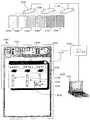
이제 도 28을 참조하면, 본 발명의 적어도 일부 특징들에 따라서 한가지 추가적인 시스템(800)이 도시된다. 시스템(800)은 상대적으로 넓은 디스플레이 스크린 또는 평면(802), 두 개의 비디오 형 프로젝터들(804 및 806), 한 개의 휴대용 평판 디스플레이 프리젠테이션 유니트(808), 랙 장착 처리기(rack mounted processor)(810), 근거리 통신망(LAN)(812), 무선 액세스 포인트(814), DVD/VCR(818), 및 스캐너/프린터(816)를 포함한다. 휴대용 프리젠테이션 유니트(808)은 도 24에 관하여 상기 기재된 프리젠테이션 유니트들과 유사하며 그러므로 여기서 다시 상세히 기재되지는 않을 것이다. 여기서, 휴대용 프리젠테이션 유니트(808)은 휴대용 카트형(cart type) 배치(arrangement)(라벨링되지 않음)의 상부에 장착되는 평판 디스플레이 스크린(838)을 포함하며 정보를 액세스 포인트(814)로 전송하고 이로부터 정보를 수신하기 위한 무선 송수신기(836)를 포함한 다고 하면 충분할 것이다.Referring now to FIG. 28, oneadditional system 800 is shown in accordance with at least some aspects of the present invention.System 800 includes a relatively wide display screen orplane 802, twovideo projectors 804 and 806, one portable flat paneldisplay presentation unit 808, a rack mountedprocessor 810 , Local area network (LAN) 812,wireless access point 814, DVD /VCR 818, and scanner /printer 816. Theportable presentation unit 808 is similar to the presentation units described above with respect to FIG. 24 and therefore will not be described here again in detail. Here, theportable presentation unit 808 includes a flatpanel display screen 838 mounted on top of a portable cart type arrangement (unlabeled) and transmits information to theaccess point 814. It would be sufficient to include awireless transceiver 836 for receiving information therefrom.

랙 장착 처리기(810)는 LAN(812)을 통해 액세스 포인트(814)에 링크되어 이로부터 정보를 수신하고 유니트(808)으로의 전송을 위해 거기에 정보를 제공한다. 추가로, 처리기(810)는 각각의 프로젝터 유니트들(804 및 806)에 뿐 아니라 DVD/VCR(818) 및 스캐너/프린터(816)에 하드웨어 내장된다(hardwired). 프로젝터 유니트(804)은 일반적으로 평면(802)의 좌측 절반 상에 정보를 투사하도록 구성되는 반면 유니트(806)은 일반적으로 평면(802)의 우측 절반에 정보를 투사하도록 배치 및 구성된다. 더 상세하게는, 유니트(804)은 평면(802)의 좌측 절반 상의 인접 공간들(820 및 822)에 나란히(side-by-side fashion) 두 개의 이미지들을 투사하도록 구성되는 반면 유니트(806)은 일반적으로 평면(802)의 우측 절반 상에 있으며 인접한 제 3 및 제 4 공간들(824 및 826)에 이미지들을 투사하도록 구성된다. 정보를 포함하는 이미지 또는 비어있는(blank) 이미지를 공간들(820 및 822)에 투사할 때, 유니트(804)은 상기 공간에 이미지 식별자(image identifier)도 투사하며, 도 28의 상기 이미지 식별자들은, 각각 828 및 830으로 라벨링되는 식별자들 1과 2를 포함한다. 유사하게, 유니트(806)은 832와 834로 라벨링되는 식별자들 3과 4를 공간들(824 및 826)에 투사한다. 상기 번호들 1, 2, 3 및 4는 시스템 동작 동안 공간들(820, 822, 824 및 826)을 서로 간에 구별하기 위해 이용된다. 적어도 일부의 구성들에서, 처리기(810)는 각각의 유니트(808)과 프로젝터들(804 및 806)을 구동하여 모든 디스플레이/표시되는 이미지들을 제어한다. 이러한 구성들에서 유니트(808)은 단순히 인터페이스이며 플리핑(flipping)/복원(retrieving) 프로세스들 이 처리기(810)에 의해 수행된다. 예를 들어, 이미지가 유니트(808)으로부터 공간(822)으로 플리핑될 때, 유니트(808)은 프로젝터(804)로 하여금 공간(822) 내의 스크린(838)으로부터 상기 이미지를 번갈아 디스플레이하게 하는 "플립(flip)" 커맨드를 처리기(810)에 전송한다. 공간(822)으로부터의 상기 이미지가 복원(retrieve)될 때, 복원(retrieve) 커맨드가 디스플레이될 유니트(808)에 역으로 복원되는 상기 이미지를 차례로 전송하는 처리기(810)로 전송된다.Therack mount processor 810 is linked to and receives information from theaccess point 814 via theLAN 812 and provides the information there for transmission to theunit 808. In addition,processor 810 is hardwired to DVD /VCR 818 and scanner /printer 816 as well as torespective projector units 804 and 806.Projector unit 804 is generally configured to project information onto the left half ofplane 802 whileunit 806 is typically arranged and configured to project information onto the right half ofplane 802. More specifically,unit 804 is configured to project two images side-by-side fashion inadjacent spaces 820 and 822 on the left half ofplane 802 whileunit 806 is configured to project two images side-by-side fashion. It is generally on the right half ofplane 802 and is configured to project images into adjacent third andfourth spaces 824 and 826. When projecting an image containing information or a blank image into thespaces 820 and 822, theunit 804 also projects an image identifier into the space, the image identifiers of FIG. ,Identifiers 1 and 2 labeled 828 and 830, respectively. Similarly,unit 806 projects theidentifiers 3 and 4 labeled 832 and 834 intospaces 824 and 826. Thenumbers 1, 2, 3 and 4 are used to distinguish thespaces 820, 822, 824 and 826 from each other during system operation. In at least some configurations,processor 810 drivesrespective unit 808 andprojectors 804 and 806 to control all displayed / displayed images. Insuch configurations unit 808 is simply an interface and flipping / retrieving processes are performed byprocessor 810. For example, when an image is flipped fromunit 808 tospace 822,unit 808 causesprojector 804 to alternately display the image fromscreen 838 inspace 822. And sends a "flip" command to theprocessor 810. When the image from thespace 822 is retrieved, a retrieve command is sent to theprocessor 810 which in turn transmits the image to be restored back to theunit 808 to be displayed.

계속하여 도 28을 참조하면, 컨트롤 아이콘들이 휴대용 유니트 디스플레이 스크린(838)의 하단 섹션 근처에 제공된다. 콘트롤 아이콘은 공간 선택 아이콘(space selection icon)들(842, 844, 846 및 848), 복원 아이콘(840) 및 전송 또는 플립(send or flip) 아이콘(850)을 포함한다. 각각의 상기 공간 선택 아이콘들(842, 844, 846 및 848)은 각각, 공간들(820, 822, 824 및 826)에 관련된 828, 830, 832 및 834에 의해 식별되는 라벨들 중 하나와 매칭(match)시키는 공간 라벨 1, 2, 3 및 4를 포함한다. 동작 시, 이미지를 스크린(838)으로부터 공간들(820, 822, 824 및 826) 중 하나로 플리핑하기 위해, 사용자는 간단히 상기 공간 선택 아이콘들(842, 844, 846 및 848) 중 하나를 선택하고 나서 플립 아이콘(850)을 선택한다. 예를 들어, 이미지를 스크린(838)으로부터 평면(822) 상의 공간(822)로 플리핑하기 위해, 사용자는 간단히 공간 선택 아이콘(844)에 이어서 플립 아이콘(850)을 선택한다. 유사하게, 공간들(820, 822, 824 및 826) 중 하나로부터 이미지를 복원(retrieve)하기 위해, 상기 사용자는 간단히 대응하는 공간 선택 아이콘(842, 844, 846 및 848)에 이어서 복원 아이콘(840)을 선택한다.With continued reference to FIG. 28, control icons are provided near the bottom section of the portableunit display screen 838. The control icon includesspace selection icons 842, 844, 846, and 848, a restoreicon 840, and a send orflip icon 850. Each of thespace selection icons 842, 844, 846, and 848 matches one of the labels identified by 828, 830, 832, and 834 related to thespaces 820, 822, 824, and 826, respectively. space labels 1, 2, 3, and 4 to match. In operation, to flip the image from thescreen 838 into one of thespaces 820, 822, 824, and 826, the user simply selects one of thespace selection icons 842, 844, 846, and 848. Thenselect flip icon 850. For example, to flip an image fromscreen 838 tospace 822 onplane 822, the user simply selectsspace selection icon 844 followed byflip icon 850. Similarly, in order to retrieve an image from one of thespaces 820, 822, 824, and 826, the user simply returns the correspondingspace selection icons 842, 844, 846, and 848 followed by a restoreicon 840. Select).

계속하여 도 28을 참조하면, 이미지가 스크린(838)으로부터 플리핑될 때, 정보가 휴대용 유니트(808)으로부터 송수신기(836)를 통해 액세스 포인트(814)로 그리고 LAN(812)을 통해 처리기(810)로 전송된다. 그 후에, 처리기(810)는 프로젝션 유니트들(804 및 806) 중 관련된 하나를 제어하여 공간들(820, 822, 824 및 826) 중 대응하는 하나로 투사되는 이미지를 갱신한다. 복원 아이콘(840)이 스크린(838)을 통해 선택될 때, 유니트들(804 및 806) 중 하나에 의해 디스플레이 되는 이미지들 중 관련된 하나가 스크린(838)을 통해 복원 및 표시될 것을 요청하는 정보가 액세스 포인트(814) 및 LAN(812)을 통해 처리기(810)로 전송된다. 본 실시예에서, 세션 동안 이전에 디스플레이된 이미지들은 처리기(810)에 의해 관련된 메모리에 저장되며, 적어도 일부 실시예들에서, 휴대용 유니트(808)에 의해 현재 디스플레이 중인 이미지만 유니트(808)의 메모리에 저장된다.With continued reference to FIG. 28, when the image is flipped from thescreen 838, information is transferred from theportable unit 808 to theaccess point 814 through thetransceiver 836 and through theprocessor 810 via theLAN 812. Is sent). Theprocessor 810 then controls the associated one of theprojection units 804 and 806 to update the projected image into the corresponding one of thespaces 820, 822, 824 and 826. When the restoreicon 840 is selected via thescreen 838, information requesting that a relevant one of the images displayed by one of theunits 804 and 806 be restored and displayed via thescreen 838 is displayed. Sent toprocessor 810 viaaccess point 814 andLAN 812. In this embodiment, the images previously displayed during the session are stored in the associated memory by theprocessor 810, and in at least some embodiments, only the image currently being displayed by theportable unit 808 is the memory of theunit 808. Are stored in.

다시 한 번 도 28을 참조하면, 유니트(808)을 통해 그리고 공간들(820, 822, 824 및 826)에 이미지들을 디스플레이하는 것에 추가하여, 적어도 일부 실시예들에서 유니트(818)을 통해 재생되는 DVD들 및 VCR들이 스크린(838) 또는 투사되는 공간들 중 하나에 표시될 수 있다. 추가로, 이미지가 스크린(838)을 통해 디스플레이되는 동안, 스크린(838) 상의 공간 제어 아이콘들 바로 위에 제공되는 프린트(print) 아이콘(870)이 선택될 수 있어서 처리기(810)로 하여금 스크린(838)을 통해 스캐너/프린터(816)를 통해 현재 상기 이미지를 프린트하게 한다. 여기서, 정보가 스크린(838)을 통한 디스플레이 또는 정보 수정을 위해 스캐너(816)를 통해 스캐닝(scan)될 수 있다. 이미지가 스캐닝 인(scan in)될 때, 처리기(810)는 상기 이미지를 LAN(812) 및 액세스 포인트(814)를 디스플레이를 위해 유니트(808)에 전송한다.Referring again to FIG. 28, in addition to displaying images viaunit 808 and inspaces 820, 822, 824, and 826, in at least some embodiments, playback is performed throughunit 818. DVDs and VCRs may be displayed onscreen 838 or one of the spaces projected. In addition, while the image is displayed through thescreen 838, aprint icon 870 that is provided directly above the space control icons on thescreen 838 can be selected to cause theprocessor 810 to display thescreen 838. To print the image currently through the scanner /printer 816. Here, information may be scanned through thescanner 816 for display through thescreen 838 or for information correction. When the image is scanned in,processor 810 sends the image toLAN 812 andaccess point 814 tounit 808 for display.

이제 도 13 내지 16을 참조하면, 본 발명의 일정한 특징들로 구성되는 다양한 방법들 및 하위-방법(sub-method)들이 기재된다. 여기 기재된 방법들 각각은 적어도 하나의 그리고 일부의 경우 상기 기재된 시스템들이나 이들의 변형 중 둘 이상 또는 모두와 함께 이용될 수 있다.Referring now to FIGS. 13-16, various methods and sub-methods that consist of certain features of the present invention are described. Each of the methods described herein may be used with at least one and in some cases two or more or both of the systems described above or variations thereof.

특히 도 13을 참조하면, 이미지들을 마스터 유니트(28)로부터 슬래브 유니트으로 플리핑하는 방법(270)이 도시된다. 또한 도 1-5를 참조하면, 방법(270)은 시스템(10)의 관계에서 기재될 것이다. 블록(272)에서 시작되어, 시스템 작동자는 상기 마스터 유니트과 상기 슬래브 프리젠테이션 유니트 또는 룸(11) 내의 청중들의 조망(viewing)을 위한 장치들을 배열한다. 블록(274)에서, 정보가 마스터 디스플레이(48)를 통해 표시된다. 블록(276)에서, 처리기(80)는 키보드(30)와 같은 입력 장치들, 유니트(28)을 통해 현재 표시되는 이미지를 슬래브 프리젠테이션 유니트들(22a 및 22b) 중 하나로 플리핑하기 위한 커맨드에 관한, HHD(200) 등을 통해 생성되는 무선 제어 신호들을 모니터링한다. 플립 커맨드가 수신되지 않는, 결정 블록(278)에서, 제어는 상기 기재된 방법이 반복되는 상기 블록(274)로 다시 되돌아 간다. 블록(278)에서, 플립 커맨드가 수신된 후, 제어는 마스터 유니트(48)이 마스터 이미지를 이미지 데이터 패킷의 일부로서 선택된 슬래브 유니트으로 전송하는 블록(280)으로 넘어간다. 블록(282)에서, 상기 선택된 슬래브 유니트은 수신된 이미지를 상기 기재된 임의의 방법들로 표시한다.With particular reference to FIG. 13, amethod 270 of flipping images from amaster unit 28 to a slab unit is shown. Referring also to FIGS. 1-5, themethod 270 will be described in the context of thesystem 10. Beginning atblock 272, a system operator arranges devices for viewing of the master unit and the slab presentation unit or the audience inroom 11. Atblock 274, information is displayed via themaster display 48. Inblock 276, theprocessor 80 sends an input device such as thekeyboard 30, a command to flip the image currently displayed via theunit 28 to one of theslab presentation units 22a and 22b. Monitor wireless control signals generated viaHHD 200, and the like. Atdecision block 278, where no flip command is received, control returns back to block 274 where the method described above is repeated. Atblock 278, after the flip command is received, control passes to block 280 where themaster unit 48 sends the master image to the selected slab unit as part of the image data packet. Atblock 282, the selected slab unit displays the received image in any of the methods described above.

이제 도 14를 참조하면, 도 13의 블록들(280 및 282)을 대체하는데 이용될 수 있는 하위-방법(284)이 플리핑된 이미지들을 이미지 식별자들과 상관시켜 이미지들이 이후에 마스터 유니트(28)을 통해 재-액세스되고, 재-표시되며 편집(edit)될 수 있도록 도시된다. 이를 위해, 하위-프로세스(284)가 상기 슬래브 유니트들에 의해 생성되는 이미지들에 고유 이미지 식별자(unique image identifier)들을 할당하는 시스템들과 함께 이용되어야 하며 여기서 상기 슬래브 유니트들은 이미지들이 생성될 때 상기 이미지들과 상기 이미지 식별자들을 포함(예컨대, 프린트)한다. 따라서, 하위-방법(284)은 도 11의 시스템(230)과의 관계에서 기재될 것이다.Referring now to FIG. 14, a sub-method 284, which may be used to replaceblocks 280 and 282 of FIG. 13, correlates the flipped images with image identifiers so that the images are subsequentlymaster unit 28. Are shown to be re-accessed, re-displayed and edited. To this end, a sub-process 284 must be used with systems that assign unique image identifiers to the images produced by the slab units, where the slab units are Include (eg, print) images and the image identifiers. Thus, the sub-method 284 will be described in relation to thesystem 230 of FIG. 11.

도 2, 3, 11, 13 및 14를 참조하면, 마스터 유니트(28)으로부터 슬래브 유니트(232)으로의 플립이 블록(278)에서 명령된 이후, 제어는 도 14의 블록(286)으로 넘어간다. 블록(286)에서, 상기 마스터 이미지는 고유 이미지 식별자 번호(예컨대, 도 11에 도시된 바와 같이 "6" 또는 "7")와 상관된다. 블록(288)에서, 마스터 처리기(80)는 상기 상관된 이미지와 이미지 식별자 번호를 마스터 메모리(88)에 저장한다. 블록(290)에서, 마스터 유니트(28)은 상기 마스터 이미지를 상기 선택된 슬래브 유니트으로 전송한다. 블록(292)에서, 상기 선택된 슬래브 유니트은 상기 이미지 식별자 번호와 함께 상기 전송된 이미지를 표시한다. 따라서, 예를 들어, 도 11에서, 슬래브 유니트(232)은 표면(250) 상에 이미지를 생성하고 상기 이미지 식별자 번호 "6"을 좌측 상단 모서리에 추가한다. 이 지점에서 이미지 플립이 완료되게 된다.2, 3, 11, 13 and 14, after a flip frommaster unit 28 toslab unit 232 is commanded atblock 278, control passes to block 286 of FIG. . Atblock 286, the master image is correlated with a unique image identifier number (eg, “6” or “7” as shown in FIG. 11). Inblock 288, themaster processor 80 stores the correlated image and image identifier number inmaster memory 88. Atblock 290,master unit 28 sends the master image to the selected slab unit. Atblock 292, the selected slab unit displays the transmitted image along with the image identifier number. Thus, for example, in FIG. 11, theslab unit 232 creates an image on thesurface 250 and adds the image identifier number "6" to the upper left corner. At this point the image flip is complete.

계속하여, 블록(294)에서, 이미지 플립이 완료된 후에, 마스터 처리기(80)는 특정 식별자 번호와 관련된 이미지에 대한 복원(retrieval) 요청을 모니터링한다. 예를 들어, 식별자 번호 "7"이 도 11에서 지시되는 바와 같이 시트(234) 상의 이미지에 붙여지는데, 시스템 작동자는 숫자 "7"의 기입(entry) 및 복원(retrieve) 키(62)(도 2를 다시 참조)의 선택을 통해 시트(234) 상에서의 상기 이미지의 복원을 요청할 수 있다. 복원이 요청되지 않는, 블록(296)에서, 제어는 블록들(292 및 294)를 통해 다시 되돌아간다. 복원 커맨드가 블록(296)에서 수신된 후, 제어는 마스터 처리기(80)가 상기 작동자에 의해 입력된 상기 식별자 번호와 상관된 이미지를 액세스하고 블록(300)에서, 마스터 유니트(28)은 마스터 디스플레이(48)를 통해 상기 상관된 이미지를 재-표시하는 블록(298)로 넘어간다.Subsequently, atblock 294, after the image flip is complete, themaster processor 80 monitors a retrieval request for the image associated with the particular identifier number. For example, the identifier number "7" is pasted to the image on thesheet 234 as indicated in FIG. 11, where the system operator enters and retrieves the key "7" 62 (FIG. 2 may be requested to restore the image on thesheet 234. Atblock 296, where restoration is not requested, control returns back toblocks 292 and 294. After the restore command is received atblock 296, control passes to amaster processor 80 accessing the image correlated with the identifier number entered by the operator and atblock 300,master unit 28 is mastered. Thedisplay 48 is passed to block 298 which re-displays the correlated image.

이제 도 15를 참조하면, 각각의 상기 슬래브 유니트들이 도 1의 실시예의 경우와 같이 고유 슬래브 유니트 식별자로써 식별가능한 플립차트(flipchart) 이미지들을 관리하는 방법(330)이 도시된다. 이를 위해, 도 1에서, 슬래브 유니트(22a)이 숫자 "1"로써 고유하게 식별될 수 있는 반면 유니트(22b)은 숫자 "2"로써 고유하게 식별될 수 있다. 도 1, 2, 3 및 15를 참조하면, 블록(334)에서, 슬래브 식별자(예컨대, 24a, 24b 등)가 각각의 슬래브 디스플레이 장치 상에 제공되며 상기 슬래브 식별자는 상기 슬래브 장치 상의 식별자에 대응하는 무선 네트워크 주소와 어떠한 방식으로 관련된다. 상기 관련된 슬래브 식별자들 및 네트워크 주소들은 마스터 유니트 메모리(88)에 저장된다. 블록(332)에서, 상기 마스터 유니트(28) 및 상기 슬래브 프리젠테이션 유니트들(22a 및 22b)은 청중들의 조망(viewing)을 위해 방(11) 내부에 배치된다.Referring now to FIG. 15, shown is amethod 330 in which each of the slab units manages flipchart images identifiable with a unique slab unit identifier as in the case of the embodiment of FIG. 1. To this end, in FIG. 1, theslab unit 22a may be uniquely identified by the number “1” while theunit 22b may be uniquely identified by the number “2”. 1, 2, 3 and 15, atblock 334, a slab identifier (eg, 24a, 24b, etc.) is provided on each slab display device and the slab identifier corresponds to an identifier on the slab device. It is in some way related to the wireless network address. The associated slab identifiers and network addresses are stored inmaster unit memory 88. Inblock 332, themaster unit 28 and theslab presentation units 22a and 22b are disposed inside theroom 11 for viewing of the audience.

블록(336)에서, 이미지가 마스터 디스플레이(48)를 통해 표시 및/또는 조작된다. 블록(338)에서, 마스터 유니트 처리기(80)는 현재 디스플레이되는 이미지가 슬래브 프리젠테이션 유니트들 중 하나로 플리핑되어야 한다고 지시하는 플립 커맨드를 모니터링한다. 플립이 지시되지 않는, 블록(340)에서, 제어는 다시 위로 그리고 블록들(336 및 338)을 통해 넘어간다. 플립이 블록(340)에서 지시되면, 제어는 상기 마스터 이미지가 작동자에 의해 특정되는 슬래브 식별자(즉, 상기 이미지가 플리핑되는 슬래브 유니트의 아이덴티티(identity))와 상관된다.Atblock 336, the image is displayed and / or manipulated via themaster display 48. Inblock 338, themaster unit processor 80 monitors a flip command indicating that the currently displayed image should be flipped into one of the slab presentation units. Atblock 340, where flip is not indicated, control passes back up and throughblocks 336 and 338. If a flip is indicated atblock 340, control is correlated with the slab identifier (ie, the identity of the slab unit to which the image is flipped) to which the master image is specified by the operator.

블록(344)에서, 마스터 처리기(80)는 상기 상관된 이미지와 슬래브 식별자 번호를 메모리(88)에 저장하며 블록(346)에서 마스터 처리기(80)는 상기 마스터 이미지를 상기 슬래브 유니트으로 전송한다. 블록(348)에서, 상기 슬래브 유니트은 수신된 이미지를 표시한다.Atblock 344,master processor 80 stores the correlated image and slab identifier number inmemory 88 and atblock 346 themaster processor 80 sends the master image to the slab unit. Atblock 348, the slab unit displays the received image.

블록(350)에서, 마스터 처리기(80)는 이미지가 복원되어야 하는 슬래브 유니트과 관련된 특정한 슬래브 식별자를 지시하는 복원 요청을 모니터링한다. 블록(352)에서, 복원 커맨드가 수신되지 않는다면, 제어는 블록(348)로 다시 넘어가며 상기 기재된 루프가 반복된다. 블록(352)에서, 복원 커맨드가 수신된 후, 제어는 처리기(80)가 마스터 메모리(88) 내의 상기 슬래브 식별자와 상관되는 이미지를 액세스하는 블록(354)로 넘어간다. 블록(356)에서, 처리기(80)는 마스터 디스플레이(48)를 통해 상기 상관된 이미지를 재-표시한다.Inblock 350, themaster processor 80 monitors for a restore request indicating a specific slab identifier associated with the slab unit for which the image should be restored. Atblock 352, if a restore command is not received, control passes back to block 348 and the loop described above is repeated. Atblock 352, after the restore command is received, control passes to block 354 whereprocessor 80 accesses an image that correlates with the slab identifier inmaster memory 88. Atblock 356,processor 80 re-displays the correlated image viamaster display 48.

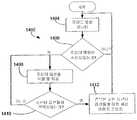
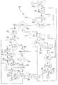
이제 도 16을 참조하면, 도 13 내지 15에 관하여 상기 기재된 임의의 방법들과 함께 마스터 유니트 처리기(80)에 의해 실행될 수 있는 방법(360)이 도시된다. 방법(360)은 세션 저장 커맨드(session store command)가 수신될 때 현재 표시되는 이미지들을 특정 프리젠테이션 유니트들과 상관시키고, 이후의 액세스를 위해 상기 상관된 이미지들 및 유니트 식별자들을 저장하며, 그리고 나서 재개 커맨드(resume command)가 수신될 때, 상기 세션 저장 커맨드가 수신되었을 때 상기 이미지들을 이와 관련된 상기 프리젠테이션 유니트들을 통해 재-표시하는 방법이다. 따라서, 예를 들어, 도 1을 참조하면, 협업 세션(collaborative session) 동안 제 1, 제 2 및 제 3 이미지들이, 각각 유니트들(22a, 22b) 및 마스터 유니트(28)을 통해 저장 키(store key)(60)가 선택될 때 표시된다고 가정한다. 여기서, 키(60)의 선택 시, 상기 제 1, 제 2 및 제 3 이미지들은, 각각 유니트들(22a, 22b 및 28)과 관련된 유니트 식별자들과 상관되고, 상기 상관된 데이터는 마스터 메모리(88)에 이미지 세트로서 저장되며 그리고 나서 유니트들(22a, 22b 및 28)의 프리젠테이션 평면들이 클리어(clear)된다. 그 후에, 작동자가 상기 저장된 이미지 세트에 대응하는 세션을 재개할 때, 처리기(28)는, 표시(presentation)를 위해, 상기 제 1 및 제 2 이미지들을, 각각 슬래브 유니트들(22a 및 22b)로 플리핑(flip)하며 상기 제 3 이미지를 디스플레이(48)를 통해 표시하여 상기 세션이 종결되는 지점에서 상기 세션이 계속될 수 있다.Referring now to FIG. 16, amethod 360 is shown that may be executed by themaster unit processor 80 in conjunction with any of the methods described above with respect to FIGS. 13-15. Themethod 360 correlates the images currently displayed when a session store command is received with specific presentation units, stores the correlated images and unit identifiers for later access, and then When a resume command is received, when the session save command is received, the images are re-displayed through the associated presentation units. Thus, for example, referring to FIG. 1, during a collaborative session the first, second and third images are stored viaunits 22a, 22b andmaster unit 28, respectively. key) 60 is assumed to be displayed when selected. Here, upon selection ofkey 60, the first, second and third images are correlated with unit identifiers associated withunits 22a, 22b and 28, respectively, the correlated data being in master memory 88. ) As a set of images and then the presentation planes of theunits 22a, 22b and 28 are cleared. Then, when the operator resumes the session corresponding to the set of stored images, theprocessor 28 sends the first and second images to theslab units 22a and 22b, respectively, for presentation. The session may continue at the point where the session ends by flipping and displaying the third image on thedisplay 48.

도 1, 2, 3 및 16을 참조하면, 블록(362)에서, 이미지들은 마스터 디스플레이(48) 및 각각의 슬래브 유니트들(22a 및 22b)을 통해 표시된다. 블럭(364)에서, 프로세서(80)는 저장 키(60)의 선택을 모니터링한다. 블럭(366)에서, 저장 키(60)가 선택되지 않으면, 제어는 다시 블럭(362)으로 넘어간다. 블럭(366)에서 일단 저장 키(60)가 선택되면, 제어는 프로세서(28)가 주(master) 디스플레이(48)를 블랭크화하고(blank), 각각의 부(slave) 유니트들이 그들 각각의 표시 표면을 블랭크화되도록 하는 각각의 부 유니트(예를 들어, 22a, 22b 등)에 신호를 전송한다. 여기서, 표시 표면들이 블랭크화되는 동안, 표시 표면들로부터의 이미지들에 대응하는 데이터는 주 메모리(88)에 또는 주 메모리(88)와 부 메모리들(예를 들어, 도 5의 119)의 조합에서 유지된다.1, 2, 3, and 16, atblock 362, images are displayed viamaster display 48 andrespective slab units 22a and 22b. Atblock 364, theprocessor 80 monitors the selection of thestorage key 60. Atblock 366, ifstore key 60 is not selected, control passes back to block 362. Once thestore key 60 is selected atblock 366, control causes theprocessor 28 to blank themaster display 48, and each slave unit to display their respective indications. A signal is sent to each sub unit (e.g. 22a, 22b, etc.) which causes the surface to be blanked. Here, while the display surfaces are blanked, the data corresponding to the images from the display surfaces is transferred to themain memory 88 or a combination of themain memory 88 and the sub memories (eg, 119 of FIG. 5). Is maintained at.

계속해서, 블럭(171)에서 프로세서(80)는 조작자(operator)로부터 후속하여 세션 이미지들에 액세스하기 위하여 사용될 수 있는 세션 식별자를 요청한다. 예를 들어, 블럭(171)에서 프로세서(80)는 주 디스플레이(48)를 통해 세션 이미지 세트를 네이밍(name)하도록 조작자를 독려하는 질의 및 세션 식별자 필드를 제공할 수 있다. 텍스트 세션 식별자가 선호된다면, 프로세서(80)는 또한 디스플레이(48)를 통해 완전한 알파벳 키보드를 포함하는 터치 선택가능 아이콘을 제공할 수 있으며, 또는 대안적으로, 세션 식별자 필드 내에서 육필을 인식할 수 있다. 블럭(171)에서 세션 식별자를 요청하는 대신, 프로세서(80)는 간단히 세션 이미지 세트에 랜덤 액세스 코드를 할당할 수 있으며, 임시적으로 디스플레이(48)를 통해 조작자에 코드를 제공할 수 있다.Subsequently, atblock 171 theprocessor 80 requests a session identifier that can be used to subsequently access the session images from the operator. For example, atblock 171 theprocessor 80 may provide a query and session identifier field that encourages the operator to name the set of session images via theprimary display 48. If a text session identifier is preferred, theprocessor 80 may also provide a touch selectable icon including a full alphabetic keyboard via thedisplay 48 or, alternatively, recognize handwriting in the session identifier field. have. Instead of requesting a session identifier atblock 171, theprocessor 80 may simply assign a random access code to the set of session images and temporarily provide the code to the operator via thedisplay 48.

블럭(369)에서, 프로세서(80)는 고유의 프리젠테이션 유니트 식별자(즉, 주 유니트(28) 또는 부 유니트들(예를 들어, 22a, 22b 등) 중 하나에 고유한 식별자)를 갖는 이미지 세트의 각각의 이미지를 서로 관련시킨다. 블럭(370)에서, 주 프로세서(80)는 각각의 이미지들이 주 메모리(88)의 주 유니트 및 부 유니트 식별자 들 중 특정한 하나와 관련되는 세션 식별자를 갖는 세션 이미지 세트를 저장한다. 블럭(370) 이후에 모든 세션 이미지들은 추후의 참조를 위해 액세스 가능한 형태로 저장된다.Atblock 369, theprocessor 80 has a unique set of presentation units (i.e., an identifier unique to one of themain unit 28 or one of the sub-units (e.g. 22a, 22b, etc.)). Relate each image of to each other. Atblock 370, themain processor 80 stores a set of session images, each session having a session identifier with which each image is associated with a particular one of the main unit and sub unit identifiers of themain memory 88. Afterblock 370 all session images are stored in an accessible form for later reference.

다음으로, 블럭(374)에서, 주 프로세서(80)는 이전의 협력 세션이 다시 시작되는 것을 나타내는 재시작(resume) 아이콘(56)을 선택하는지 모니터링하여, 저장된 이미지 세트가 다시 액세스되고 표시되어야만 한다. 블럭(376)에서, 재시작 명령이 수신되지 않으면, 제어는 다시 블럭(374)으로 넘어간다. 블럭(376)에서 일단 재시작 명령이 수신되면, 제어는 블럭(377)으로 넘어간다.Next, atblock 374, themain processor 80 monitors to select aresume icon 56 indicating that the previous collaboration session is to be restarted, so that the set of stored images must be accessed and displayed again. Atblock 376, if no restart command is received, control passes back to block 374. Once the restart command is received atblock 376, control passes to block 377.

블럭(377)에서, 주 프로세서(80)는 시스템 조작자에게 이전에 저장된 이미지 세트에 대응하는 세션 식별자를 제공하도록 촉구하는 요청을 제공한다. 본 명세서에서, 프롬프트(prompt)는 식별자를 명시하기 위하여 터치 감응성(touch sensitive) 아이콘들(예를 들어, 숫자들, 알파벳들 등)의 적절한 세트와 함께 세션 식별자 필드 및 텍스트 쿼리를 포함할 수 있다.Inblock 377, themain processor 80 provides a request to urge a system operator to provide a session identifier corresponding to a previously stored set of images. In this specification, a prompt may include a session identifier field and a text query with an appropriate set of touch sensitive icons (eg, numbers, alphabets, etc.) to specify the identifier. .

블럭(378)에서, 입력된 세션 식별자와 관련된 이미지 세트가 메모리(88)로부터 복원되고, 블럭(380)에서 세트의 이미지들이 주 디스플레이 및 부 유니트들을 통해 디스플레이 되어 이전 세션이 그것이 중단된 곳에서 계속될 수 있다. 블럭(380) 이후에, 제어는 상기 개시된 공정이 계속되는 블럭(362)까지 다시 넘어간다.Atblock 378, the image set associated with the entered session identifier is restored frommemory 88, and atblock 380 the images of the set are displayed through the primary display and the sub-units so that the previous session continues where it was interrupted. Can be. Afterblock 380, control passes back to block 362 where the process disclosed above continues.

후속 액세스를 위한 시스템 프리젠테이션 유니트들을 통해 동시에 표시되는 이미지 세트들을 저장할 수 있는 것에 더하여, 본 발명의 적어도 몇몇 실시예들에 서는, 이미지들이 부 유니트들로 넘어가는지 아닌지와 관계 없이 후속 액세스 및 저장을 위해 개별 이미지들이 선택가능할 수 있는 것으로 기대된다. 예를 들어, 다시 도 2 및 3을 참조하여, 적어도 몇몇 경우에, 저장 키(60)가 한번 선택되었을 때, 현재 디스플레이(48)를 통해 표시되는 이미지가 저장되고, 키(60)가 곧바로 두번째로 선택되었을 때(예를 들어, 마우스의 더블-클릭과 같은 동작), 프로세서(80)가 이미지 세트로서 세션 이미지들의 전체 컴플리먼트(compliment)를 저장하도록 프로그래밍되도록 주 프로세서(80)가 프로그래밍될 수 있다. 단일 이미지들이 후속 액세스를 위하여 저장되면, 몇몇 경우에 이러한 이미지들은 이미지가 저장될 때 발생하는 협력적 세션과 관련된 세션 세트에 부가될 수 있다. 대안적으로, 몇몇 경우에, 단일 이미지가 저장될 때, 프로세서(80)는 세션 이미지 세트의 저장에 대하여 상기 개시된 것과 유사한 공정을 수행할 수 있으며, 후속하여 이미지에 다시 액세스하기 위하여 사용될 수 있는 시스템 조작자로부터 특정 텍스트 또는 숫자 이미지 식별자를 요청한다.In addition to being able to store image sets that are simultaneously displayed via system presentation units for subsequent access, in at least some embodiments of the present invention, subsequent access and storage may be performed irrespective of whether or not the images are passed to secondary units. It is expected that the individual images may be selectable. For example, referring again to FIGS. 2 and 3, in at least some cases, when thestorage key 60 is selected once, the image currently displayed via thedisplay 48 is stored, and the key 60 is immediately second. When selected as (e.g., a double-clicking operation of a mouse), themain processor 80 may be programmed such that theprocessor 80 is programmed to store the full complement of session images as a set of images. Can be. If single images are stored for subsequent access, in some cases these images may be added to the session set associated with the collaborative session that occurs when the image is stored. Alternatively, in some cases, when a single image is stored,processor 80 may perform a process similar to that disclosed above for storage of a session image set, which may then be used to access the image again. Request a specific text or numeric image identifier from the operator.

이미지들이 개별적으로 저장되면, 계속해서 도 2 및 도 3을 참조로 하여, 복원 키(62)가 선택될 때, 이미지들이 주 메모리로부터 또는 부 표시 장치들 중 하나로부터 복원될 수 있기 때문에, 프로세서(80)는 이미지가 복원될 수 있는 가능한 소스들 또는 이러한 이미지들에 액세스하기에 적합한 툴들을 나타내는 옵션 메뉴를 제공할 수 있다.If the images are stored separately, then with reference to Figs. 2 and 3, since the images can be restored from the main memory or from one of the sub-display devices, when therecovery key 62 is selected, the processor ( 80 may provide an options menu indicating possible sources from which the image may be reconstructed or tools suitable for accessing such images.

도 17을 참조로 하여, 도 2의 주 유니트(28)과 유사한 주 프리젠테이션 유니트(528)은 주 유니트(528)이 하부 한계 영역에서 터치 감응성 아이콘들의 세트를 제공하는 것으로 도시된다. 여기서, 재시작 아이콘(56), 전송 아이콘(58), 저장 아이콘(60) 및 복원 아이콘(62) 및 왼쪽 및 오른쪽 넘김 아이콘들(68 및 70) 각각은 도 2의 유사하게 넘버링된(numbered) 키들과 관련하여 상기 개시된 기능들을 반영하는 기능들을 가지고, 따라서 설명을 간략화하기 위하여 본 명세서에서 다시 상술되지 않을 것이다. 유니트(528)을 통해 제공되는 아이콘 세트와 유니트(28)을 통해 제공되는 키 세트간의 주요한 차이는 도 2의 숫자 패드(67)가 도 17의 썸 네일(thumb nail) 스케치 바(450)에 의해 교체되었다는 것이다. 여기서, 이미지가 주 유니트(528)으로부터 부 유니트들 중 하나로 넘겨질 때마다, 넘겨진 이미지의 썸 네일이 바(450)를 통해 표시될 것이다. 도 17에서, 두 개의 예시적인 썸 네일 스케치들이 숫자들(452 및 450)에 의해 식별된다. 여기서, 부 유니트들 중 하나에 의해 표시되고 있는 주 디스플레이(48)를 통한 이미지의 재표시를 위하여, 이미지에 액세스하기 위해 이미지에 인가되는 이미지 식별자 또는 특정 부 유니트을 식별하는 대신, 시스템 조작자는 간단히 썸 네일 스케치들(예를 들어, 452, 454 등) 중 하나를 선택하고, 디스플레이(48)를 통해 이미지를 재표시하기 위하여 아이콘들(62)을 복원할 수 있는 것으로 기대된다.Referring to FIG. 17, amain presentation unit 528 similar to themain unit 28 of FIG. 2 is shown where themain unit 528 provides a set of touch sensitive icons in the lower limit area. Here, each of therestart icon 56, thetransfer icon 58, thesave icon 60 and the restoreicon 62 and the left andright flip icons 68 and 70 are similarly numbered keys of FIG. Functions that reflect the functions disclosed above in connection with the description, and thus will not be described again herein in order to simplify the description. The main difference between the icon set provided through theunit 528 and the key set provided through theunit 28 is that thenumber pad 67 of FIG. 2 is driven by the thumbnail sketch bar 450 of FIG. 17. It was replaced. Here, each time an image is passed from themain unit 528 to one of the sub-units, a thumbnail of the passed image will be displayed via thebar 450. In FIG. 17, two exemplary thumb nail sketches are identified bynumbers 452 and 450. Here, instead of identifying an image identifier or a particular sub unit applied to the image for accessing the image, for re-display of the image via theprimary display 48 being displayed by one of the sub units, the system operator may simply It is expected that one of the nail sketches (eg, 452, 454, etc.) can be selected and theicons 62 can be reconstructed to redisplay the image via thedisplay 48.

적어도 몇몇 경우에, 주 유니트(528)으로부터 부 유니트들 중 임의의 것으로 넘겨진 모든 이미지들이 저장되고, 시스템 조작자가 협력 세션을 제거하고 대응하는 썸 네일 스케치들(예를 들어, 452, 454 등)이 바(450)에 부가될 때까지 주 메모리(88)내에 유지되는 것으로 기대된다. 여기서, 넘겨진 이미지들의 개수가 종종 오래 끄는 협력 세션들 동안의 경우인 부 프리젠테이션 유니트들의 개수를 초과하 면, 시스템 조작자는 이미지들이 부 유니트들을 통해 현재 표시되는지 여부에 관계없이 모든 넘겨진 이미지들에 여전히 빠르고 용이하게 액세스할 수 있을 것이다. 아이콘들(64 및 66)은 조작자가 재표시를 위해 특정 이미지들에 대한 많은 개수의 썸네일 스케치들을 그래픽적으로 복원할 수 있는 왼쪽 및 오른쪽 스크롤링 아이콘들이다. 몇몇 경우에, 몇몇 경우에, 넘겨진 이미지들 및 넘겨지지 않은 모든 저장된 이미지들은 주 메모리(88)에 저장되고, 바(450)에서 선택가능한 썸네일 스케치들로서 나타날 것으로 기대된다.In at least some cases, all images passed from themain unit 528 to any of the sub-units are stored, and the system operator removes the cooperative session and the corresponding thumbnail sketches (eg, 452, 454, etc.) It is expected to remain inmain memory 88 until added to bar 450. Here, if the number of images passed in exceeds the number of secondary presentation units, which is often the case during long-running cooperative sessions, the system operator is still present in all the transferred images regardless of whether the images are currently displayed through the secondary units. It will be quick and easy to access.Icons 64 and 66 are left and right scrolling icons that allow the operator to graphically restore a large number of thumbnail sketches for specific images for redisplay. In some cases, it is expected that in some cases, the passed over images and all stored images not passed over are stored inmain memory 88 and appear as selectable thumbnail sketches inbar 450.

다시 도 24를 찹조하여, 적어도 몇몇 실시예들에서, 본 발명은 다중 프리젠테이션 유니트들이 이용가능하고 프리젠테이션 유니트들 중 임의의 유니트이 주 또는 부 유니트으로서 기능할 수 있으면, 시스템 사용자가 유니트들 중 하나를 주 유니트으로서 식별하는 것을 신속하게 돕고, 주 및 선택된 부 유니트들을 연관시키기 위하여 더 큰 유니트들의 세트로부터 부 유니트들로서 동작하기 위하여 유니트들의 서브-세트를 선택하며, 주 및 부 유니트들 중에 이미지들을 넘기기 위한 툴을 제공하도록 소프트웨어에서 실행될 수 있다. 이 때문에, 다시 도 24를 참조하여, 본 실시예에서, 프리젠테이션 유니트들(702, 704, 706, 708, 710 및 712)은 예를 들어, 개인 사무실, 회의실, 현관 또는 카페테리아의 입구 등과 같은 공공 장소에서 등의 다양한 목적을 위해 사용될 수 있는 것으로 가졍될 것이다. 이 때문에, 각각의 유니트들은 수평면을 자유롭게 회전하는 스탠드(716)의 상부상에 장착된 평면 패널 디스플레이(714)를 포함하여, 유니트들은 한 위칭에서 다른 위치로 쉽게 이송될 수 있다. 두 개 이상의 유니트들이 유니트들 중 하나가 주 유니트으로서 사용 되고 다른 유니트 또는 유니트들이 부 유니트으로서 사용될 회의 공정을 용이하게 하도록 함께 사용될 때, 회의 공간에 서로 관련된 다수의 유니트들이 구비되고, 그 후 회의 공정을 용이하게 하도록 애플리케이션을 구동할 수 있는 것으로 기대된다.Referring back to FIG. 24, in at least some embodiments, the present invention provides that a system user can use one of the units if multiple presentation units are available and any of the presentation units can function as a primary or secondary unit. To quickly identify as a primary unit, select a sub-set of units to act as secondary units from a larger set of units to associate primary and selected secondary units, and pass images among the primary and secondary units It can be executed in software to provide a tool for. For this reason, referring again to FIG. 24, in this embodiment, thepresentation units 702, 704, 706, 708, 710 and 712 are public, such as, for example, a private office, a conference room, an entrance to a porch or cafeteria, or the like. It will be assumed that it can be used for various purposes, such as in a place. To this end, each of the units includes aflat panel display 714 mounted on top of thestand 716 that freely rotates the horizontal plane so that the units can be easily transferred from one location to another. When two or more units are used together to facilitate a conference process in which one of the units is used as the primary unit and the other unit or units are used as the secondary unit, there are multiple units associated with each other in the conference space and thereafter the conference process. It is expected to be able to run the application to facilitate this.

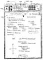
이제 도 25를 참조로 하여, 상기 개시된 공정과 일치하는 방법(730)이 개시된다. 도 24도 또한 참조하여, 블럭(732)에서, 다수의 디스플레이 유니트들(예를 들어, 702, 704, 706, 708, 710 및 712)이 제공되며, 각각의 디스플레이 유니트들이 고유의 무선 어드레스를 갖는다. 예를 들어, 디스플레이 유니트(702)은 무선 어드레스 00425A1을 가질 수 있고, 무선 어드레스 54478B1을 가질 수 있으며, 유니트(706)은 무선 어드레스 89908B1을 가질 수 있다. 공정 블럭(734)에서, 다수의 디스플레이 유니트들이 회의 공간에 구비된다.Referring now to FIG. 25, amethod 730 is disclosed consistent with the disclosed process. Referring also to FIG. 24, atblock 732, a number of display units (eg, 702, 704, 706, 708, 710, and 712) are provided, each display unit having a unique radio address. . For example, thedisplay unit 702 may have a wireless address 00425A1, may have a wireless address 54478B1, and theunit 706 may have a wireless address 89908B1. Atprocess block 734, multiple display units are provided in the conference space.

공정 블럭(736)에서, 회의 공간의 각각의 유니트들이 턴온되면, 시스템 조작자는 유니트들 중 하나가 주 유니트으로서 사용될 것을 지시한다. 이 때문에, 도 24에서 도시된 바와 같이, 적어도 몇몇 실시예들에서, 유니트들 중 하나(예를 들어, 702)가 턴온될 때마다, 시스템 조작자에게 유니트을 주 유니트으로서 선택하는 방법을 지시하는 정보(즉, 초기 인터페이스)가 유니트의 디스플레이(예를 들어, 714)를 통해 표시된다. 이와 관련하여, 명령(720)들은 유니트(702)을 주 유니트으로서 식별하기 위하여 선택가능한 MASTER 아이콘(722)과 함께 디스플레이(714)를 통해 제공될 수 있다. 유사한 명령들 및 마스터 아이콘(예를 들어, 724 참조)이 각각의 유니트들(704, 706, 708, 710 및 712)을 통해 제공된다. 조작자가 유니트들 중 하나가 주 유니트이 될 것임을 나타낼 때, 디폴트값에 의하여(by default), 회의 공간내의 다른 유니트들이 가능한 부 유니트들로서 식별된다. 본 실시예에서, 조작자가 디스플레이(714)를 통해 MASTER 아이콘(722)을 선택하여, 유니트(702)은 주 유니트이 됨을 나타내는 것으로 가정될 것이다.Atprocess block 736, once each unit of the conference space is turned on, the system operator indicates that one of the units will be used as the main unit. For this reason, as shown in FIG. 24, in at least some embodiments, each time one of the units (eg, 702) is turned on, information instructing the system operator how to select the unit as the primary unit ( That is, the initial interface is displayed via the unit's display (eg 714). In this regard,instructions 720 may be provided viadisplay 714 with aselectable MASTER icon 722 to identifyunit 702 as the main unit. Similar commands and a master icon (see eg 724) are provided through therespective units 704, 706, 708, 710 and 712. When the operator indicates that one of the units will be the main unit, by default, the other units in the conference space are identified as possible subunits. In this embodiment, it will be assumed that the operator selects theMASTER icon 722 via thedisplay 714 so that theunit 702 becomes the main unit.

계속해서, 블럭(738)에서, 조작자가 주 유니트으로서 유니트(702)을 선택한 이후, 유니트(702)은 회의 공간 내의 다른 프리젠테이션 유니트들(704, 706, 708, 710 및 712)을 식별하기 위하여 회의 공간을 무선으로 폴링한다. 각각의 유니트들(704, 706, 708, 710 및 712)이 유니트들이 가능한 부 유니트들로서 자기 자신을 식별하는 것을 요청하는 폴링 신호를 수신할 때, 각각의 유니트(704, 706, 708, 710 및 712)은 고유한 무선 네트워크 어드레스에 의해 부 유니트을 식별하는 주 유니트(702)으로 다시 정보 패킷을 전송한다. 예를 들어, 상기 예시적인 어드레스들과 일치하여, 유니트(704)은 고유 어드레스 54478B1을 포함하는 정보 패킷을 전송하고, 유니트(706)은 고유 어드레스 89908B1을 포함하는 정보 패킷을 전송한다. 유니트(702)이 가능한 부 유니트들로부터 리턴 정보 패킷을 수신할 때, 유니트(702)은 각각의 가능한 부 유니트을 식별하고, 고유한 단순 식별자를 각각의 부 유니트들과 연관시키며, 그 후 구성 공정을 용이하게 한다. 이 때문에, 본 실시예에서, 주 유니트(702)은 5개의 개별 부 유니트들(704, 706, 708, 710 및 712)을 식별하고, 단순 식별자들(1, 2, 3, 4 및 5)을 각각 개별 부 유니트들과 연관시킨다.Subsequently, atblock 738, after the operator selectsunit 702 as the main unit,unit 702 may identifyother presentation units 704, 706, 708, 710 and 712 in the conference space. Poll the meeting space wirelessly. When eachunit 704, 706, 708, 710 and 712 receives a polling signal requesting that the units identify themselves as possible subunits, eachunit 704, 706, 708, 710 and 712 Transmits the information packet back to theprimary unit 702, which identifies the secondary unit by a unique wireless network address. For example, consistent with the example addresses above,unit 704 sends an information packet that includes unique address 54478B1, andunit 706 sends an information packet that includes unique address 89908B1. Whenunit 702 receives a return information packet from possible subunits,unit 702 identifies each possible subunit, associates a unique simple identifier with each subunit, and then proceeds with the configuration process. To facilitate. For this reason, in this embodiment, themain unit 702 identifies fiveindividual subunits 704, 706, 708, 710 and 712, and identifies thesimple identifiers 1, 2, 3, 4 and 5. Each associated with a separate subunit.

도 25 및 26을 참조로 하여, 블럭(738)에서, 5개 부 유니트들을 식별한 이후에, 주 유니트(702)은 단순 식별자 라벨들을 각각에 할당하는 각각의 5개 부 유니트들(704, 706, 708, 710 및 712)로 다시 정보 패킷을 전송한다. 본 실시예에서, 식별자 라벨들은 유니트들(704, 706, 708, 710 및 712)로 각각 전송되는 숫자들(1, 2, 3, 4 및 5)을 포함한다. 부 유니트이 단순 식별자 라벨을 수신할 때, 유니트은 디스플레이 스크린을 통해 라벨을 디스플레이한다. 도 26에서, 디스플레이된 단순 라벨들은 752, 754, 756, 758 및 760에서 보여진다.25 and 26, atblock 738, after identifying the five sub-units, themain unit 702 assigns each of the fivesub-units 704, 706 to assign simple identifier labels to each. 708, 710, and 712 send the information packet back. In this embodiment, the identifier labels include thenumbers 1, 2, 3, 4 and 5 transmitted to theunits 704, 706, 708, 710 and 712, respectively. When the secondary unit receives the simple identifier label, the unit displays the label via the display screen. In FIG. 26, the displayed simple labels are shown at 752, 754, 756, 758, and 760.

또한, 도 25 및 26을 참조로 하여, 블럭(738)에서, 주 유니트(702)은 상부 근처의 주 라벨(750) 지정, 회의 공정을 용이하게 하기 위하여 주 유니트(702)과 함께 사용될 회의 공간 내의 부 유니트들의 서브-세트를 선택하기 위한 명령들(780) 및 각각의 부 유니트들(704, 706, 708 등)과 연관된 단순 라벨들(예를 들어, 752, 754 등)에 대응하는 아이콘들을 포함하는 구성 인터페이스를 제공한다. 예를 들어, 아이콘(762)은 라벨(752)과 관련되어, 부 유니트(704)과 관련된다. 유사하게, 아이콘들(766, 768, 770 및 772)은 라벨들(754, 756, 758 및 760)과 관련되어, 부 유니트들(706, 708, 710 및 712)과 개별적으로 관련된다. 엔터 아이콘(774)이 또한 주 유니트 디스플레이의 하부 근처에 제공된다. 여기서, 명령들(780)과 일치하여, 부 유니트들(704-712)의 서브-세트는 아이콘들(762, 766, 768, 770 및 772)의 서브-세트럴 선택하고, 그 후 ENTER 아이콘(774)을 선택함으로써 선택될 수 있다. 예를 들어, 회의 세션 동안 주 유니트(702)과 함께 사용될 유니트들로서 부 유니트들(706, 708)을 선택하기 위하여, 조작자는 아이콘들(766, 768, 770)을 선택하고, 그 후 ENTER 아이콘(774)을 선택한다. 활동을 명시하는 부 유니트 서브-세트를 모니터링하는 이러한 공정은 도 25에서 블럭들(740 및 742)에 의해 나타난다.25 and 26, atblock 738,main unit 702 is designated amain label 750 near the top, a meeting space to be used withmain unit 702 to facilitate the conference process.Instructions 780 for selecting a subset of sub-units within the icons and icons corresponding to simple labels (eg, 752, 754, etc.) associated with each sub-unit 704, 706, 708, etc. It provides a configuration interface that includes. For example,icon 762 is associated withlabel 752 and associated withsub unit 704. Similarly,icons 766, 768, 770, and 772 are associated withlabels 754, 756, 758, and 760 individually withsubunits 706, 708, 710, and 712. Anenter icon 774 is also provided near the bottom of the main unit display. Here, in line with theinstructions 780, the sub-set of the sub-units 704-712 selects a sub-set of theicons 762, 766, 768, 770, and 772, and then the ENTER icon ( 774). For example, to selectsecondary units 706, 708 as units to be used withprimary unit 702 during a conference session, the operator selectsicons 766, 768, 770, and then selects the ENTER icon ( 774). This process of monitoring the sub unit sub-sets specifying activity is represented byblocks 740 and 742 in FIG.

일단 ENTER 아이콘(774)이 선택되면, 공정 블럭(744)에서, 주 유니트(702)은 주 라벨(750) 지정을 포함하는 제어 인터페이스를 제공하고, 선택된 부 유니트들의 서브-세트로 주 이미지들을 넘기고 선택된 부 유니트들의 서브-세트로부터 이미지들을 복원하기에 적합한 아이콘들을 제공한다. 이 때문에, 도 27을 참조하여, 주 유니트(702)은 개별적인 선택된 부 유니트들(706, 708 및 710)의 서브-세트에 대한 개별적인 넘김/복원 아이콘(782, 784 및 786)을 각각 제공한다. 넘김/복원 아이콘들(782, 784 및 786)은 유사하고 유사한 방식으로 동작하기 때문에, 설명을 간략화하기 위하여 본 명세서에서는 아이콘(784)만이 상세히 개시될 것이다. 아이콘(784)은 넘김 화살표 아이콘(769) 및 복원 화살표 아이콘(771)을 포함한다. 넘김 아이콘(769)이 선택될 때, 현재 주 디스플레이를 통해 디스플레이되는 이미지는 넘겨지거나 아이콘(784)과 관련된 부 유니트(708)(즉, 단순 라벨(754과 관련되는 유니트(708))으로 전송된다. 유사하게, 복원 화살표 아이콘(771)이 선택될 때, 현재 부 유니트(708)을 통해 디스플레이되는 이미지가 복원되고 주 디스플레이 유니트(702)을 통해 디스플레이된다. 현재 회의 공정을 종료하기 위한 END 아이콘(788)이 제공된다.Once theENTER icon 774 is selected, atprocess block 744, themain unit 702 provides a control interface that includes aprimary label 750 designation, and passes the main images to a subset of the selected sub-units. Provide icons suitable for reconstructing images from a selected subset of sub-units. To this end, with reference to FIG. 27,main unit 702 provides separate flip / restoreicons 782, 784, and 786, respectively, for a subset of individual selectedsubunits 706, 708, and 710. Because the flip / restoreicons 782, 784, and 786 operate in a similar and similar manner, onlyicons 784 will be disclosed in detail herein for the sake of brevity.Icon 784 includesflip arrow icon 769 and restorearrow icon 771. When theflip icon 769 is selected, the image currently displayed via the primary display is passed over or sent to thesub unit 708 associated with the icon 784 (ie, theunit 708 associated with the simple label 754). Similarly, when the restorearrow icon 771 is selected, the image currently displayed through thesub unit 708 is restored and displayed via themain display unit 702. The END icon ( 788 is provided.

따라서, 다중 사용 전자 디스플레이들이 개별적인 사용 및 혼합된 사용을 위하여 다양한 상이한 방식으로 구성되 수 있다는 것을 유념해야 한다. 또한 디스플레이들이 무선 통신을 위해 구비되고 디스플레이가 구성 공정을 능률화되도록 하는 소프ㅌ웨어가 제공될 수 있다는 것을 또한 유념해야 한다.Thus, it should be noted that multi-use electronic displays can be configured in a variety of different ways for individual use and mixed use. It should also be noted that the displays may be provided for wireless communication and that software may be provided that allows the display to streamline the configuration process.

이제 도 29를 참조로 하여, 본 발명의 특정 실시예들의 적어도 몇몇 측면들 과 일치하는 하나 이상의 시스템(890)이 도시된다. 또한 도 28을 참조로 하여, 도 28과 관련하여 상기 개시된 시스템(800)과 각각 유사한 시스템(890)은 제1 및 제2 서브 시스템(900 및 901)을 포함한다. 따라서, 각각의 시스템들(900 및 901)은 휴대용 주 프리젠테이션 유니트, 제1 및 제2 프로젝터 유니트, 디스플레이 스크린, 랙(rack) 장착 프로세서, 로컬 영역 네트워크 및 무선 액세스 포인트를 포함하며, 이들 모두는 도 29에서 개별적으로 라벨링되지 않는다. 도 28에 도시된 실시예에서와 같이, 각각의 프로젝터들은 두 개의 개별적 이미지들을 디스플레이 스크린상으로 투사하도록 구성된다. 예를 들어, 도 29에서, 서브시스템(900)의 프로젝터들 중 하나는 제1 및 제2 개별 공간들(904 및 906)로 제1 및 제2 개별 이미지들을 투사하는 한편, 서브시스템(901)의 프로젝터들 중 하나는 각각 제1 및 제2 공간들(903 및 905)로 제1 및 제2 이미지들을 투사한다. 도 29에서, 상기 개시된 구성요소들에 더하여, 로컬 영역 네트워크가 광 지역 네트워크(WAN)를 통해 링크된다.Referring now to FIG. 29, one ormore systems 890 are shown consistent with at least some aspects of certain embodiments of the present invention. Referring also to FIG. 28, asystem 890 similar to thesystem 800 disclosed above with respect to FIG. 28, respectively, includes first andsecond subsystems 900 and 901. Thus, each of thesystems 900 and 901 includes a portable main presentation unit, first and second projector units, a display screen, a rack mounted processor, a local area network and a wireless access point, all of which are Not individually labeled in FIG. 29. As in the embodiment shown in FIG. 28, each projector is configured to project two separate images onto a display screen. For example, in FIG. 29, one of the projectors insubsystem 900 projects the first and second individual images into first and secondseparate spaces 904 and 906, whilesubsystem 901 is located. One of the projectors of projects the first and second images into the first andsecond spaces 903 and 905, respectively. In FIG. 29, in addition to the components disclosed above, a local area network is linked via a wide area network (WAN).

여전히 도 29를 참조하여, 적어도 몇몇 구성들에 있어서, 시스템(901)은 시스템(900)으로부터 원격으로 위치될 것이고, 휴대용 프리젠테이션 유니트들 중 어느 하나는 주 프리젠테이션 유니트으로서 사용될 수 있는 것으로 기대된다. 또한, 적어도 몇몇 애플리케이션에 있어서, 시스템 사용자가 표시를 수행하기 위하여 주 프리젠테이션 유니트들 중 하나를 사용할 때, 대응 서브시스템에서 발생하는 모든 활동이 다른 서브시스템에서 복제되는 것으로 기대된다. 예를 들어, 시스템 사용자가 주 디스플레이 스크린(902)상의 정보를 변경할 때, 이러한 변화는 본질적으로 실시간으로 원격 주 표시 스크린(907)상에서 복제될 것이다. 또한, 시스템 사용자 가 주 표시 공간(902)으로부터 부 표시 공간들(예를 들어, 904, 906 등) 중 하나로 이미지를 넘길 때, 넘김 동작은 시스템(901) 내부에서 또한 복제될 것이다. 예를 들어, 시스템 사용자가 시스템(900)의 공간(902)으로부터 공간(904)으로 이미지를 넘긴다면, 동일한 이미지가 서브시스템(901)의 공간(907)으로부터 공간(903)으로 넘겨질 것이다. 유사하게, 시스템 사용자가 공간(906)으로부터 주 표시 공간(902)까지 다시 복원한다면, 공간(905)으로부터의 이미지는 또한 서브시스템(901)의 마스터 스페이스(907)까지 다시 복원될 수 있다.Still referring to FIG. 29, in at least some configurations,system 901 will be located remotely fromsystem 900, and any of the portable presentation units is expected to be used as the main presentation unit. . In addition, in at least some applications, when a system user uses one of the main presentation units to perform an indication, it is expected that all activity that occurs in the corresponding subsystem is replicated in the other subsystem. For example, when a system user changes information on theprimary display screen 902, this change will be replicated on the remoteprimary display screen 907 in essence in real time. In addition, when the system user passes an image from theprimary display space 902 to one of the sub display spaces (eg, 904, 906, etc.), the flipping operation will also be replicated inside thesystem 901. For example, if a system user hands over an image fromspace 902 ofsystem 900 tospace 904, the same image will be handed over fromspace 907 ofsubsystem 901 tospace 903. Similarly, if the system user restores back fromspace 906 tomain display space 902, the image fromspace 905 may also be restored back tomaster space 907 ofsubsystem 901.

또한 적어도 일부 실시예에서 마스터 표시 공간(907)에서 이미지를 변경하는 동작(activity)도 마스터 표시 공간(902)에서 유사한 이미지를 자동적으로 그리고 필수적으로 실시간으로 변경할 것이다. 유사하게, 적어도 일부 실시예에서 공간(907)을 통한 이미지들의 플리핑(flipping) 및 복원(retrieving)은 서브시스템(900)에서 발생하는 유사한 동작에 의해 야기될 것이다.In addition, in at least some embodiments, the activity of changing an image in themaster display space 907 will automatically and essentially in real time change similar images in themaster display space 902. Similarly, in at least some embodiments flipping and retrieval of images throughspace 907 will be caused by similar operation occurring insubsystem 900.

이제 도 30을 참조하면, 본 발명의 일부 실시예의 최소한 일부 측면들이 일치하는 다른 실시예(950)가 도시된다. 도 28도 참조하면, 시스템(950)은 시스템(950)이 휴대용 마스터 프리젠테이션 유니트(951), 디스플레이 스크린(953) 및 제 1 및 제 2 프로젝터(964 및 966)를 포한하는 점에서 시스템(800)과 유사하다. 도 28에 도시된 다른 구성요소들은 본 설명을 간략화하기 위해서 도 30에서는 도시하지 않는다. 도 30의 시스템과 도 28에서 도시된 시스템 사이의 주요한 차이는, 유니트(951)이 도 30에서 도시된 것과 같은 세로도(portrait view)에서 도 31에서 도시된 것과 같은 가로도(landscape view)로 화살표(957)에 의해 지시된 것과 같이 회전될 수 있는 플랫 패널 디스플레이(955)를 포함한다는 점이다. 여기서 디스플레이(955)가 세로 방향에서 가로 방향으로 회전될 때, 적어도 일부 실시예에서 적어도 두 가지 변화가 자동적으로 발생한다는 것이 고려된다. 첫 번째로, 투사된 슬래브 이미지의 수는 유니트(955) 방향에 좌우될 수 있다. 이를 위해서 적어도 일부 실시예에서, 디스플레이(955)가 도 30에서 도시된 것과 같은 세로 방향일 때 각각의 프로젝터(964 및 966)는 두 개의 독립적인 인접 이미지들을 투사하도록 프로그램 될 수 있다는 것이 고려된다. 예를 들면, 도 30에서 도시된 것과 같이, 프로젝터(964)는 인접한 공간(956 및 958)에 제 1 및 제 2 이미지를 투사하고, 프로젝터(966)는 인접한 공간(960 및 962)에 제 1 및 제 2 이미지를 투사하며, 여기서 투사된 이미지들의 각각은 세로 형태를 갖는다. 도 31을 참조하면, 유니트(955)이 가로 방향으로 회전되면, 프로젝터를 구동하는 프로세서는 각각의 프로젝터(964 및 966)가 하나의 가로 이미지만을 투사하도록 자동적으로 재설정되도록 프로그램 된다. 도 31에서, 프로젝터(964)는 가로 공간(980)에 제 1 가로 이미지를 투사하고, 프로젝터(966)는 가로 공간(982)에 제 2 이미지를 투사한다.Referring now to FIG. 30, anotherembodiment 950 is shown in which at least some aspects of some embodiments of the present invention coincide. Referring also to FIG. 28, thesystem 950 is asystem 800 in that thesystem 950 includes a portablemaster presentation unit 951, adisplay screen 953, and first andsecond projectors 964 and 966. Similar to). Other components shown in FIG. 28 are not shown in FIG. 30 to simplify the present description. The main difference between the system of FIG. 30 and the system shown in FIG. 28 is that theunit 951 is in landscape view as shown in FIG. 31 in a portrait view as shown in FIG. 30. It includes aflat panel display 955 that can be rotated as indicated byarrow 957. Here, it is contemplated that at least two changes occur automatically in at least some embodiments when thedisplay 955 is rotated from portrait to landscape. First, the number of slab images projected can depend on theunit 955 orientation. To this end, in at least some embodiments, it is contemplated that eachprojector 964 and 966 may be programmed to project two independent adjacent images when thedisplay 955 is in a portrait orientation as shown in FIG. 30. For example, as shown in FIG. 30,projector 964 projects the first and second images inadjacent spaces 956 and 958, andprojector 966 first inadjacent spaces 960 and 962. And projecting a second image, wherein each of the projected images has a vertical form. Referring to FIG. 31, when theunit 955 is rotated in the horizontal direction, the processor driving the projector is programmed to automatically reset eachprojector 964 and 966 to project only one horizontal image. In FIG. 31, theprojector 964 projects the first horizontal image in thehorizontal space 980, and theprojector 966 projects the second image in thehorizontal space 982.

둘째로 디스플레이가 세로 방향에서 가로 방향으로 회전될 때, 디스플레이(955)를 통해 표시되는 제어 아이콘들(954)은 우선 슬래브 표시 공간으로 만들어지는 변화에 일치하도록 변경되어, 제어 아이콘들(954)이 디스플레이(955)의 가시 부분(viewing portion) 내에 더 잘 배향된다. 이를 위해서, 도시된 것과 같이, 도 30에서 4개의 슬래브 공간 선택 아이콘들이 도시되었지만, 도 31에서는 오직 2개의 슬래브 공간 선택 아이콘들이 도시되며, 슬래브 공간의 각각의 하나는 슬래브 공 간(980 및 982)의 각각의 하나에 대응한다. 전술한 내용으로부터, 다양한 변경과 변형이 본 발명의 신규한 개념의 본질적인 사상과 범위에서 벗어나지 않고 만들어질 수 있다. 본 개시는 본 발명의 예시를 목적으로 한 것이며, 도시된 특정 실시예로 본 발명을 제한하고자 함이 아님을 이해할 것이다. 본 개시는 첨부한 청구범위에 의해서 청구범위의 범위 내에 속할 상기 모든 변형들을 포함하고자 한다. 예를 들어, 마스터 유니트(28)은 간단히 카메라가 장착된 종래 화이트보드일 수 있으며, 여기서 이미지가 마스터 유니트에서 슬래브 유니트들 중 하나로 플리핑 되면, 카메라는 마스터 유니트을 통해 효시된 이미지의 사진을 찍고, 표시를 위해 그 이미지를 선택된 슬래브 유니트에 전송한다.Secondly, when the display is rotated from portrait to landscape, thecontrol icons 954 displayed through thedisplay 955 are first changed to match the changes made to the slab display space, so that thecontrol icons 954 It is better oriented in the viewing portion of thedisplay 955. To this end, as shown, four slab space selection icons are shown in FIG. 30, but only two slab space selection icons are shown in FIG. 31, with each one of the slab spaces being aslab space 980 and 982. Corresponds to each one of. From the foregoing, various changes and modifications can be made without departing from the spirit and scope of the novel concept of the invention. It is to be understood that this disclosure is for purposes of illustration of the invention and is not intended to limit the invention to the particular embodiments shown. This disclosure is intended to cover all such modifications as would fall within the scope of the claims by the appended claims. For example, themaster unit 28 may simply be a conventional whiteboard equipped with a camera, where the image is flipped from one master unit to one of the slab units, the camera takes a picture of the stale image through the master unit, Transfer the image to the selected slab unit for display.

또한, 본원에서 설명된 모든 프리젠테이션 유니트들은 벽걸이형 레일에 프리젠테이션 유니트들을 장착하는 장착 부재를 포함하며, 프리젠테이션 유니트들을 위한 다른 타입의 지지 구조물이 고려될 수 있다는 것이 이해되어야 한다. 예를 들면, 마스터 유니트(28)은 이젤(easel)형 어셈블리에 의해 지지될 수 있으며, 또는 카트(cart) 장착형 어셈블리 일 수 있으며, 여기서 카트는 설비(facility) 내에서 유니트의 용이한 움직임을 용이하게 하는 다리 바퀴(caster)를 포함한다.In addition, it should be understood that all the presentation units described herein include a mounting member for mounting the presentation units on a wall-mounted rail, and other types of support structures for the presentation units may be considered. For example, themaster unit 28 may be supported by an easel type assembly, or may be a cart mounted assembly, where the cart facilitates easy movement of the unit within the facility. And caster to make it easy.

더구나 간단한 지우개 및 프린터가 상기에 설명되었지만, 다양한 타입의 프린터와 지우개가 고려되고, 본 발명의 다양한 실시예들과 함께 사용될 수 있다는 것이 이해되어야 한다. 예를 들면, 일부 경우에 슬래브 표시 표면은 고정된(rigid) 화이트보드 부재에 의해 제공될 수 있으며, 상술된 프린터들은 표시 표면을 따라 또는 이에 상대적으로 움직이는 플로터일 수 있으며(즉, 고정된 화이트 보드는 사실상 플로터에 대해 이동될 수 있음), 지우개는 표시 표면 상에 이미지들을 제공하고 이들로부터 이미지들을 제거하도록 유사한 방식으로 지지되고 이동될 수 있다.Moreover, while simple erasers and printers have been described above, it should be understood that various types of printers and erasers are contemplated and may be used with various embodiments of the present invention. For example, in some cases the slab display surface may be provided by a rigid whiteboard member, and the printers described above may be plotters that move along or relative to the display surface (ie, a fixed whiteboard). Can be moved relative to the plotter), the eraser can be supported and moved in a similar manner to provide images on and remove images from the display surface.

게다가 슬래브 및 마스터 프리젠테이션 유니트 모두, 영구적인 벽 장착, 움직임을 용이하게 하기 위한 다리 바퀴를 구비하거나 또는 구비하지 않는 이젤형 지지 구조물(도 24, 26 및 27을 참조), 유니트을 경계벽에 고정시키는 천장 장착 구조물 등을 포함하는 임의의 방식으로 지지될 수 있다.In addition, both the slab and master presentation units have permanent wall mounting, an easel support structure with or without casters to facilitate movement (see FIGS. 24, 26 and 27), ceilings for fixing the unit to the boundary wall. And may be supported in any manner, including mounting structures and the like.

본원에 설명된 시스템이 오직 2개의 슬래브 유니트만을 포함하지만, 일부 시스템은 셋 이상의 슬래브 유니트들을 포함할 것이라는 것이 이해되어야 한다. 추가로, 일부 시스템은 한 가지 이상의 타입의 슬래브 유니트을 포함할 수 있다. 예를 들면, 도 11 및 12를 다시 참조하면, 유니트(232)과 같은 프린터 타입의 슬래브 유니트이 도 12의 시스템(251)에 추가될 수 있으며, 따라서 시스템은 프린터(232) 뿐만 아니라 플랫 패널 유니트(232a 및 252b)을 포함한다. 다른 슬래브 유니트 조합들도 고려된다.Although the system described herein includes only two slab units, it should be understood that some systems will include more than two slab units. In addition, some systems may include more than one type of slab unit. For example, referring back to FIGS. 11 and 12, a slab unit of a printer type, such asunit 232, may be added tosystem 251 of FIG. 12, so that the system may include a flat panel unit (not just printer 232). 232a and 252b). Other slab unit combinations are also contemplated.

적어도 일부 경우에, 모든 시스템 유니트들(예를 들어 마스터 및 슬래브 유니트)은 이상적인 구성 및 기능을 가질 수 있으며, 따라서 이미지들은 임의의 유니트들을 통해 편집될 수 있고, 임의의 유니트으로부터 플리핑 되거나 복원될 수 있다. 따라서 예를 들면 마스터 유니트(28)과 같은 3개의 유니트이 시스템을 포함하는 경우, 작동자는 강화된 협력 방식으로 편집 및 플리핑 및 복원 유니트들 사이에서 이동할 수 있다.In at least some cases, all system units (e.g. master and slab units) may have an ideal configuration and function, so that images can be edited through any units and can be flipped or restored from any unit. Can be. Thus, for example, if three units, such asmaster unit 28, comprise a system, the operator can move between the editing and flipping and restoration units in an enhanced collaborative manner.

또한 하나의 간단한 레일(40) 구성이 상술되지만, 다른 후크 투 후크 타입 레일, 마스터 및 슬래브 유니트에 장착된 휠을 수용할 수 있는 레일, 이들의 종단을 통해서만 장착 가능한 레일(예를 들어, 레일은 윗 방향 또는 앞 방향 움직임을 통해 장착된 유니트들의 제거를 제한할 수 있음 - 이는 유니트이 상대적으로 비싼 경우에 특히 중요함), 및 유니트들이 레일 부제들(40)에 유니트들을 보다 효과적으로 고정하도록 하는 고정 구조물을 포함하는 다른 시스템을 포함하는 많은 여러 가지 타입의 레일 구성을 본 발명은 고려한다.In addition, while onesimple rail 40 configuration is described above, other hook-to-hook type rails, rails that can accommodate wheels mounted on master and slab units, rails that can be mounted only through their ends (e.g., Up or forward movement can limit the removal of the mounted units-this is especially important if the unit is relatively expensive), and a fixing structure that allows the units to more effectively secure the units to therail subtitles 40. The present invention contemplates many different types of rail configurations, including other systems that include.

도 28에서 도시된 것과 같이, 상기 구성요소들 외에, 임의의 발명적인 시스템들은, 미팅 중에 사용하게 위해서라거나, 미팅에서 기록하기 위해서라거나, 또는 문서들이 시스템을 통해 일람 또는 편집을 위해 재빨리 스캔될 수 있도록, 미팅 참석자들을 위해 표시된 이미지들의 복사본들을 인쇄하기 위한 표준 크기의 프린터/스캐너(예를 들어, 8 1/2" x 11", 법정 사이즈 등)도 포함할 수 있다.As shown in FIG. 28, in addition to the above components, any inventive systems may be quickly scanned for use during a meeting, for recording at a meeting, or for documents to be viewed or edited through the system. May include a standard size printer / scanner (eg, 8 1/2 "x 11", court size, etc.) for printing copies of the displayed images for meeting attendees.

더구나 도 1 및 22를 참조하면, 적어도 일부의 경우에, 마스터 및 슬래브 유니트들(28, 221, 22b) 중 하나 또는 전부가 마스터 및 슬래브 유니트들 및 그 위에 표시되는 이미지들을 제어하기 위해서 랩톱 또는 개인용 컴퓨터를 사용하는 발표자로부터 원격에 위치될 수 있다(798). 여기에서 예를 들면 만약 시카고에 있는 발표자가 시카고에 위치한 유니트(800) 디스플레이 상이 표시를 생성한다면, 그 표시는 즉시 뉴욕 컨퍼런스 룸에 위치된 마스터 유니트(28)(도 1을 다시 참조) 상에 즉시 제공될 수 있다. 여기서 만약 사용자가 마스터 이미지가 제 1 슬래브 유니트(22a)으로 플리핑 되어야 한다는 것을 지시한다면, 뉴욕에 위치한 이미지는 뉴욕 에 있는 제 1 슬래브 유니트(22a)으로 플리핑 된다. 유사하게 뉴욕에 위치한 슬래브 유니트으로부터의 이미지들은 시카고에서 입력된 명령들을 통해 편집을 위해 마스터 유니트(28)으로 복원될 수 있다. 상술된 경우에, 도 22를 참조하면, 원격 제어 유니트(200)(도 10a를 다시 참조)은 뉴욕에 위치한 프리젠테이션을 구동하기 위해서 네트워크 링크(810)(예를 들어 인터넷)를 통해 마스터 유니트(28)과 통신한다.Furthermore, referring to FIGS. 1 and 22, in at least some cases, one or all of the master andslab units 28, 221, 22b may be used by a laptop or personal computer to control the master and slab units and the images displayed thereon. It may be located 798 remotely from the presenter using the computer. Here, for example, if a presenter in Chicago creates an indication on theunit 800 display located in Chicago, the indication is immediately on the master unit 28 (see FIG. 1 again) located in the New York conference room. Can be provided. Here, if the user indicates that the master image should be flipped to thefirst slab unit 22a, the image located in New York is flipped to thefirst slab unit 22a in New York. Similarly, images from slab units located in New York can be restored tomaster unit 28 for editing via commands entered in Chicago. In the case described above, referring to FIG. 22, the remote control unit 200 (see FIG. 10A again) is connected to the master unit via a network link 810 (eg, the Internet) to drive a presentation located in New York. 28).

일부 경우에서 유니트(800)은 발표자가 원격 프리젠테이션을 기록하는 것을 돕기 위해서 마스트 및 슬래브 유니트 이미지들의 각각의 표시(representation)를 포함할 수 있다. 이를 위해 도 22의 디스플레이(812)는 마스터 유니트 이미지 박스(814) 및 제 1 및 제 2 슬래브 유니트 이미지 섬네일 스케치들(thumbnail sketch)(816 및 818)을 포함한다. 이 경우에서 플리핑 및 복원은 한 박스 또는 스케치 또는 다른 것들로부터 이미지들을 드래그(dragging)하는 것만큼 간단할 수 있다. 예를 들면, 제 1 슬래브 유니트(22a)으로 플리핑하기 위해서, 발표자는 박스(814) 내의 마스터 이미지를 섬네일(816)로 간단히 드래그 할 수 있다. 유사하게 제 2 슬래브 유니트 이미지를 복원하기 위해서, 사용자는 제 2 슬래브 유니트 섬네일(818)을 마스터 박스(814)로 간단히 드래그 할 수 있다. 또한 이러한 특징들은 마스터 및 슬래브 이미지들을 국지적으로 제어하기 위해서 유니트(800)의 맥락에서 사용될 수도 있다(예를 들어 프리젠테이션 유니트과 동일한 공간에 위치한 유니트(800)과 함께).In some cases,unit 800 may include respective representations of mast and slab unit images to assist the presenter in recording the remote presentation. To this end, thedisplay 812 of FIG. 22 includes a masterunit image box 814 and first and second slab unit image thumbnail sketches 816 and 818. In this case, flipping and reconstruction can be as simple as dragging images from one box or sketch or others. For example, to flip to thefirst slab unit 22a, the presenter can simply drag the master image in thebox 814 to thethumbnail 816. Similarly, to reconstruct the second slab unit image, the user can simply drag the secondslab unit thumbnail 818 into themaster box 814. These features may also be used in the context ofunit 800 to control master and slab images locally (eg withunit 800 located in the same space as the presentation unit).

일부의 경우에, 마스터 유니트(28) 및 슬래브 유니트들(22a, 22b)의 서브-세 트는 시카고에 위치될 수 있지만, 하나 이상의 슬래브 유니트들은 뉴욕에 원격으로 위치된다. 여기서 발표자는 상술된 것과 유사한 방식으로 여러 슬래브 유니트들에 대한 플리핑 프로세스를 제어할 수 있다.In some cases, the sub-set ofmaster unit 28 andslab units 22a, 22b may be located in Chicago, while one or more slab units are located remotely in New York. Here the presenter can control the flipping process for the various slab units in a manner similar to that described above.

부가하여, 도 24를 다시 참조하면, 적어도 일부의 경우에서, 휴대용 인터페이스 장치(handheld interface device; 731)가 마스터 및 슬래브 유니트을 지정하기 위해서 제공될 수 있다. 이를 위해, 장치(731)는 가능한 마스터 및 슬래브 유니트들을 식별하고 디스플레이(733)를 통해 선택 가능한 아이콘들을 제공하기 위해서 유니트들(702, 704, 706, 708, 710 및 712)을 무선으로 선택(poll)하도록 프로그램 될 수 있다. 여기서 일단 마스터 유니트과 슬래브 유니트들의 서브-세트가 선택되면, 장치(731)는 상응하는 유니트들(702, 704 등)에 지정 정보(designation information)를 전송할 수 있으며, 적절한 구성이 마스터 유니트으로부터의 그리고 마스터 유니트으로의 이미지들의 플리핑/복원을 용이하게 하도록 한다. 구성 후에, 제어 인터페이스 도구들은 마스터 유니트 또는 장치(731) 중 하나, 또는 둘 다를 통해 제공될 수 있다.In addition, referring again to FIG. 24, in at least some cases, ahandheld interface device 731 may be provided to designate a master and slab unit. To this end, thedevice 731 wirelessly polls theunits 702, 704, 706, 708, 710 and 712 to identify possible master and slab units and to provide selectable icons via thedisplay 733. Can be programmed. Here, once a sub-set of the master unit and the slab units is selected, thedevice 731 can send designation information to the correspondingunits 702, 704, etc., with the appropriate configuration being from the master unit and the master. To facilitate flipping / recovery of the images into the unit. After configuration, control interface tools may be provided through one or both of the master unit ordevice 731.

또한 도 24의 시스템이 무선 통신의 문맥으로 설명되었지만, 적어도 일부 경우에서 통신은 배선에 의해 접속된 후크업(hookup)에 의할 수 있다.Also while the system of FIG. 24 has been described in the context of wireless communication, in at least some cases the communication may be by hookup connected by wiring.

게다가 도 24-27에 대해서 상술된 프로세스를 돕는 구성은 롤 다운(roll down) 또는 프로젝션 타입 유니트들 등과 같은 다른 타입의 프리젠테이션 유니트들과 함께 사용될 수 있으며, 도 25의 모든 단계들을 필요로 하지 않을 수 있다. 예를 들면, 마스터 유니트은 미리 정해질 수 있거나, 또는 한 가지 유니트 타입이 다 른 유니트 타입들과 함께 사용될 때 항상 마스터 유니트일 수 있다. 예를 들면, 하나의 유니트이 전자 플랫 패널 터치스크린이고 다른 유니트들은 롤 다운 타입 유니트인 경우, 터치스크린 유니트은 항상 마스터 유니트일 수 있고, 작동 중에 컨퍼런스 공간에서 다른 유니트들을 선택할 수 있다.In addition, the configuration assisting the process described above with respect to FIGS. 24-27 may be used with other types of presentation units, such as roll down or projection type units, and may not require all the steps of FIG. 25. Can be. For example, a master unit may be predetermined or may always be a master unit when one unit type is used with other unit types. For example, if one unit is an electronic flat panel touch screen and the other units are roll down type units, the touch screen unit may always be a master unit and may select other units in the conference space during operation.

다음으로 소정의 발명적인 특징을 포함하는 예시적인 인터페이스는 도 29에 도시된 시스템(890)의 맥락에서 설명될 것이며, 여기서 정보 발표자는 서브시스템(900)을 구성하는 구성요소들을 포함하는 컨퍼런스 룸 내의 컨퍼런스 참석자와 서브시스템(901) 구성요소들을 포함하는 원격 컨퍼런스 룸에 있는 참석자들의 다른 그룹에 정보를 표시하기 위해서 마스터 유니트(902)을 사용한다. 컨퍼런스 참석자들의 적어도 일부는 컨퍼런스에 참석하기 위해서 예를 들어 랩톱 컴퓨터(911, 913, 915 등)를 포함하는 개인용 인터페이스 장치를 가지고 있고 이를 사용할 수 있다. 도 29에서 랩톱(911 및 913)은 서브시스템(900)에 LAN을 통해 연결되어 있고, 랩톱(915)은 WAN(920)을 통해 서브시스템(900)에 연결된다. 도시된 실시예에서, 랩톱(911 및 913)은 랩톱 사용자가 이의 랩톱 디스플레이, 마스터 유니트(902)을 통해 표시된 이미지 또는 슬래브 프리젠테이션 공간(969)을 통해 표시된 슬래브 이미지들(예를 들어 904, 906 등)을 볼 수 있도록 서브시스템(900)을 포함하는 컨퍼런스 공간 내에서 사용된다. 유사하게 하나 이상의 랩톱은 서브-서브시스템(901)과 관련된 컨퍼런스 공간 내에서 사용될 수 있다. 또한 도시된 실시예에서, 랩톱(915)은 컨퍼런스 활동 내에 패치(patch)하고 감시/참가하기 위해서 원격으로 사용된다. 이하에서는 다르게 지시되지 않는 한 랩톱(911, 913, 915 등)은 개인용 인터페이스 장치와 같이 언급될 것이다.An example interface that includes certain inventive features will next be described in the context of thesystem 890 shown in FIG. 29, where the information presenter is in a conference room that includes the components that make up thesubsystem 900. Themaster unit 902 is used to present information to other groups of attendees in the remote conference room, including the conference attendees andsubsystem 901 components. At least some of the conference attendees have and may use a personal interface device including, for example, a laptop computer (911, 913, 915, etc.) to attend the conference. In FIG. 29,laptops 911 and 913 are connected to subsystem 900 via a LAN, andlaptop 915 is connected to subsystem 900 via aWAN 920. In the illustrated embodiment, thelaptops 911 and 913 may have a laptop user displaying its laptop display, an image displayed via themaster unit 902, or slab images displayed via the slab presentation space 969 (eg, 904, 906). Etc. are used within the conference space that includessubsystem 900 for viewing. Similarly, one or more laptops may be used within the conference space associated with the sub-subsystem 901. Also in the illustrated embodiment,laptop 915 is used remotely to patch and monitor / join within conference activities. In the following,laptops 911, 913, 915, etc. will be referred to as personal interface devices unless otherwise indicated.

도 29를 여전히 참조하고, 도 32 및 33도 함께 참조하면, 본 예시에서 프리젠테이션 중의 특정 지점에서, 마스터 유니트(902)은 스크린 샷(screen shot; 100)과 일치하는 특성을 갖는 인터페이스를 발표자에게 제공하고, 발표자는 4개의 이미지들(1022, 1024, 1026 및 1028)의 예시들이 슬래브 프리젠테이션 표면(969) 상에 표시되도록 하였다고 가정할 것이다. 따라서 서브시스템(900)을 포함하는 컨퍼런스 룸 내의 컨퍼런스 참석자들은 마스터 유니트(902)을 통해 표시된 이미지뿐만 아니라 도 33에 도시된 4개의 이미지들의 각각을 관측할 수 있다.Still referring to FIG. 29 and referring also to FIGS. 32 and 33, at a particular point in the presentation in this example, themaster unit 902 presents the presenter with an interface that has characteristics consistent with the screen shot 100. In presenting, the presenter will assume that examples of fourimages 1022, 1024, 1026, and 1028 have been displayed on theslab presentation surface 969. Thus, conference attendees in the conferenceroom including subsystem 900 may observe each of the four images shown in FIG. 33 as well as the image displayed throughmaster unit 902.

도 29, 32 및 33을 다시 참조하면, 유사한 프리젠테이션 성능을 갖는 2개의 서브-시스템(900, 901)이 연결된 적어도 일부 실시예에서, 서브-시스템들(예를 들어, 서브시스템(900)) 중 하나를 통해 표시된 모든 이미지들은 다른 서브시스템(예를 들어 서브시스템(901))의 구성요소들에 의해 반복되거나 재-표시된다. 따라서 예를 들면, 도 32 및 33의 이미지들은 마스터 유니트(902) 및 공간(969)을 통해 표시되는 동안, 5개의 동일한 이미지들이 유니트(907) 및 슬래브 프리젠테이션 공간(971)을 통해 동시에 표시된다. 유사하게 적어도 일부 실시예에서, 서브-시스템(900)의 구성요소들에 의해 수행되는 임의의 활동은 서브-시스템(901)의 구성요소들을 통해 필수적으로 실시간으로 반복될 수 있으며, 따라서 서브시스템(900 및 901)과 관련된 개별적인 컨퍼런스 공간 내의 참석자들은 이미지 활동들을 동시에 볼 수 있다. 따라서 예를 들면, "2"라고 라벨링된 공간(969)의 서브-공간을 통해 표시된 이미지가 변경되면, "2"라고 라벨링된 공간(971)의 서브-공간을 통해 표시 되는 이미지는 마찬가지로 변경될 것이며, 따라서 서브-시스템(900)을 통해 표시되는 어떠한 이미지들도 서브-시스템(901)을 통해 마찬가지로 표시될 것이다. 마스터 유니트(902)을 통해 표시되는 이미지가 변경되는 다른 경우에서, 유니트(907)을 통해 표시되는 유사한 이미지도 동일한 방식을 ㅗ변경된다.Referring back to FIGS. 29, 32, and 33, in at least some embodiments in which twosub-systems 900, 901 with similar presentation capabilities are connected, the sub-systems (eg, subsystem 900) All images displayed through one of them are repeated or re-displayed by components of another subsystem (eg, subsystem 901). Thus, for example, while the images of FIGS. 32 and 33 are displayed through themaster unit 902 and thespace 969, five identical images are simultaneously displayed through theunit 907 and theslab presentation space 971. . Similarly, in at least some embodiments, any activity performed by the components ofsub-system 900 may be repeated essentially in real time through the components ofsub-system 901 and thus the subsystem ( Attendees in separate conference spaces associated with 900 and 901 can view image activities simultaneously. Thus, for example, if an image displayed through the sub-space of thespace 969 labeled "2" is changed, the image displayed through the sub-space of thespace 971 labeled "2" may be changed as well. Thus, any images displayed throughsub-system 900 will likewise be displayed throughsub-system 901. In other cases where an image displayed via themaster unit 902 is changed, similar images displayed via theunit 907 are changed in the same manner.

도 32를 계속 참조하면, 인터페이스 스크린 샷(1000)은 16:9의 종횡비 디스플레이 스크린을 통해 표시하기에 적절한 포맷으로 도시되며, 여기서 디스플레이 스크린은 세로 방향이다(즉, 긴 치수 16이 수직이고, 짧은 치수 9는 수평임). 도시된 것과 같이, 16:9 스크린이 세로 방향인 경우, 적어도 일부 실시예에서 예시적인 스크린 샷(100)은 스크린 샷(1000)의 상부 에지를 따라 위치된 도구 영역(1002)과 그 아래의 워크스페이스 영역(1004)을 포함한다. 도 32에 도시된 일반적인 16:9 세로 레이아웃에 대해서, 많은 컨퍼런스 참석자들에게 익숙한 폼팩터(form factor)를 유지하기 위해서 통상적인 기계적 플립 차트 패드(flip chart pad) 또는 통상적인 개인용 컴퓨터 스크린과 유사한 치수를 갖는 워크스페이스 영역(1004)을 제공하는 것이 유리하다는 것이 인식된다. 통상적인 플립 차트 패드는 대략 2 단위의 폭 대 3 단위의 높이의 종횡비를 가지며, 개인용 컴퓨터의 디스플레이 스크린은 통상적으로 대략 4 단위 폭 대 3 단위 높이의 종횡비를 갖는다. 여기서 적어도 일부 실시예에서, 마스터 유니트은 도 32에서 도시된 것과 같이 세로 가로인 경우에, 영역(1004)은 2:3 종횡비(예를 들어 2 폭 대 3 높이)를 가지고, 나머지 공간은 도구 영역(1002)을 제공하는데 사용된다. 아래에 더 자세히 설명되겠지만, 마스터 유니트이 가로 방향이면(도 40), 워크스페이스 영역(1216)은 4:3 종횡비(즉 4 폭 대 3 높이)를 갖고, 나머지 공간은 도구 영역(1202)을 제공하는데 사용된다.With continued reference to FIG. 32,interface screenshot 1000 is shown in a format suitable for display through a 16: 9 aspect ratio display screen, where the display screen is in portrait orientation (ie,long dimension 16 is vertical and short).Dimension 9 is horizontal). As shown, when the 16: 9 screen is in portrait orientation, in at least some embodiments theexemplary screenshot 100 is atool area 1002 located along the upper edge of thescreenshot 1000 and the work below it. Thespace area 1004 is included. For the typical 16: 9 portrait layout shown in FIG. 32, dimensions similar to a conventional mechanical flip chart pad or a conventional personal computer screen are used to maintain a form factor familiar to many conference attendees. It is recognized that it is advantageous to provide aworkspace area 1004 having. Conventional flip chart pads have an aspect ratio of approximately two units wide by three units high, and a display screen of a personal computer typically has an aspect ratio of approximately four units wide to three units high. Here in at least some embodiments, where the master unit is vertically horizontal as shown in FIG. 32,area 1004 has a 2: 3 aspect ratio (eg, 2 width to 3 height), and the remaining space is in the tool area ( 1002). As will be described in more detail below, if the master unit is in landscape orientation (FIG. 40),workspace area 1216 has a 4: 3 aspect ratio (ie, 4 width to 3 height), and the remaining space providestool area 1202. Used.

도 32를 다시 참조하면, 16:9 종횡비 스크린에서, 상부 에지를 따라 도구 영역을 제공하거나 적어도 일부 실시예에서 스크린의 하부 에지를 따라(도시되지 않음) 도구 영역을 제공함으로써, 최대 크기 2:3 종횡비(즉 2 폭 대 3 높이)가 형성될 수 있다. 여기서 2:3 포맷 워크스페이스 영역(1004)을 제공하기 위해서 18:5 포맷 도구 영역(1002)이 구성될 수 있다.Referring again to FIG. 32, in a 16: 9 aspect ratio screen, providing a tool region along an upper edge or, at least in some embodiments, by providing a tool region along a lower edge of the screen (not shown), maximum size 2: 3 Aspect ratios (ie 2 widths to 3 heights) may be formed. Herein, an 18: 5format tool area 1002 may be configured to provide a 2: 3format workspace area 1004.

18:5 도구 영역 포맷은 이 비율이 16:9 디스플레이 스크린에서 얻어질 수 있는 가장 큰 2:3 워크스페이스 영역(1004)과 일반적으로 양립가능하기 때문에 주로 선택되었다. 여기서 워크스페이스 영역(1004)이 2:3 내지 3:4 범위 내에 치수화 되어야 한다는 일반적인 교시와 양립할 수 있는 다른 스크린 레이아웃이 고려된다는 것이 이해되어야 한다. 이런 목적을 위하여, 도 32를 참조한 다른 실시예에서, 스크린의 상부 에지를 따라 툴 영역(1002)을 배치하는 대신, 툴 영역(1002)은 바닥(bottom) 에지를 따라 배치될 수 있다. 유사하게, 툴 영역(1002)은 스크린의 상부 및 바닥 에지들을 따라 배치된 제 1 및 제 2 독립 툴 영역들로 분할될 수 있고 여기서 각각의 툴 영역들은 결합될 때 18:5 비율을 형성하도록 36:5 종횡비 또는 몇몇 다른 비율들을 가진다. 다른 실시예들에서 워크피스 영역(1004)은 16:9 스크린에 대해 가능한 최대 크기보다 작게 만들어질 수 있지만 여전히 목표된 2:3 내지 3:4 종횡비를 가진다. 세로 및 가로 방향에서 4:3 종횡비 디스플레이 스크린들 및 가로방향에서 16:9 종횡비 디스플레이 스크린에 해당하는 다른 예시적인 스크린 샷들은 이후에 도 40, 42 및 43을 참조하여 기술된다.The 18: 5 tool region format was chosen mainly because this ratio is generally compatible with the largest 2: 3workspace region 1004 that can be obtained on a 16: 9 display screen. It should be understood here that other screen layouts are considered that are compatible with the general teaching thatworkspace area 1004 should be dimensioned in the range of 2: 3 to 3: 4. For this purpose, in another embodiment with reference to FIG. 32, instead of placingtool area 1002 along the upper edge of the screen,tool area 1002 may be disposed along the bottom edge. Similarly,tool area 1002 can be divided into first and second independent tool areas disposed along the top and bottom edges of the screen, where each tool area is combined to form an 18: 5 ratio when combined. Have a: 5 aspect ratio or some other ratio. In other embodiments theworkpiece region 1004 can be made smaller than the maximum possible size for a 16: 9 screen but still has a targeted 2: 3 to 3: 4 aspect ratio. Other example screen shots corresponding to 4: 3 aspect ratio display screens in portrait and landscape orientation and 16: 9 aspect ratio display screen in landscape orientation are described below with reference to FIGS. 40, 42, and 43.

여전히 도 32를 참조하여, 라벨이 의미하는 바와 같이, 툴 영역(1002)은 유니트(902)를 통해 슬래브(slave) 프리젠테이션 공간(969)상에 디스플레이된 정보를 변화시키기 위한 프리젠터에 의해 선택할 수 있는 다수의 온 스크린 아이콘들을 포함한다. 온 스크린 아이콘들은 예를들어 터치, 스타일러스, 마우스 제어 포인팅 아이콘의 이동 및 작동, 트랙 볼, 등등 같은 임의의 다른 방식으로 선택할 수 있다. 이런 설명을 위해, 만약 다르게 지시되지 않으면, 유니트(902)가 디스플레이 스크린상 하나의 위치를 터치할 때 위치 및 터칭 작용 위치를 식별하기 위한 센서들을 포함하는 것이 가정된다.Still referring to FIG. 32, as the label means, thetool area 1002 can be selected by the presenter for changing the information displayed on theslab presentation space 969 via theunit 902. It contains a number of on-screen icons. On-screen icons can be selected in any other way, such as, for example, the movement and operation of a touch, stylus, mouse control pointing icon, track ball, and the like. For this description, it is assumed that unless otherwise indicated, it includes sensors for identifying the position and the touching action position when theunit 902 touches one position on the display screen.

도 29 및 34를 지금 참조하여, 도 34는 적어도 몇몇의 본 발명의 실시예들에 따른 퍼스널 인터페이스 장치들(911,913,915, 등등) 중 하나의 사용자에게 표시될 수 있는 예시적인 스크린 샷(1030)을 도시한다. 도 32 및 33을 참조하여, 도 34에 도시된 바와 같이, 원격 사용자에게 표시된 정보는 서브시스템(900)을 포함하는 회의 공간내 회의 출석자들에게 표시된 모든 정보를 포함한다. 따라서, 도 34에 도시된 바와 같이, 예시적 스크린 샷(1030)은 4개의 윈도우를 포함하고, 각각의 윈도우는 마스터 유니트(902)를 통하여 현재 디스플레이된 각각의 이미지들 및 공간(969)에 표시된 슬래브 이미지들(1022,1024,1026 및 1028)에 해당한다. 도 34에서, 윈도우(1032)는 마스터 유니트(902)를 통해 디스플레이된 이미지에 해당하고, 윈도우(1034,1036,1038 및 1040)는 도 33에 도시된 바와 같이 각각 슬래브 이미지들(1022,1024,1026 및 1028)에 해당한다.Referring now to FIGS. 29 and 34, FIG. 34 illustrates an example screen shot 1030 that may be displayed to a user of one ofpersonal interface devices 911, 913, 915, etc. in accordance with at least some embodiments of the present invention. do. With reference to FIGS. 32 and 33, as shown in FIG. 34, the information displayed to the remote user includes all the information displayed to meeting attendees in the conferencespace including subsystem 900. Thus, as shown in FIG. 34, exemplary screen shot 1030 includes four windows, each window displayed in each image andspace 969 currently displayed viamaster unit 902. Corresponding toslab images 1022, 1024, 1026 and 1028. In FIG. 34,window 1032 corresponds to an image displayed throughmaster unit 902, andwindows 1034, 1036, 1038, and 1040show slab images 1022, 1024, as shown in FIG. 33, respectively. 1026 and 1028).

도 32 및 34를 다시 참조하고, 특히 툴 영역(1002) 및 워크스페이스 영 역(1032)을 포함하는 스크린 샷(1000) 같은 도 34의 윈도우(1032)를 참조하여, 마스터 유니트(902)에 해당하는 윈도우(1032)는 툴 영역(1031)뿐 아니라 섹션들(1002 및 1004)과 동일한 방식으로 배열된 워크스페이스 영역(1033)을 포함한다. 도시된 바와 같이, 툴 영역(1031)은 도 32에 도시된 툴 아이콘들에 해당하는 스크린 선택 가능 아이콘들의 전체 보완물(complement)을 포함한다.Reference is again made to FIGS. 32 and 34, and in particular with reference to thewindow 1032 of FIG. 34, such as screen shot 1000 includingtool area 1002 andworkspace area 1032, corresponding tomaster unit 902. Thewindow 1032 includes thetool area 1031 as well as theworkspace area 1033 arranged in the same manner as thesections 1002 and 1004. As shown, thetool area 1031 includes a full complement of screen selectable icons corresponding to the tool icons shown in FIG. 32.

적어도 몇몇의 본 발명의 실시예들에서, 이미지 정보를 변경할 수 있는 마스터 유니트(902)를 사용하는 프리젠터 외에, 임의의 회의 출석자는 워크스페이스 섹션(1033)을 통하여 이미지 정보를 변경할 수 있고, 이미지가 섹션(1033)을 통하여 변경될 때, 상기 변경들은 마스터 유니트(902)를 통하여 표시된 이미지를 변경하여 마스트 유니트 이미지를 반복하는 모든 이미지들을 변경하기 위하여 필수적으로 실시간으로 사용된다. 따라서, 적어도 몇몇 실시예들에서, 모든 또는 적어도 하나의 출석자의 서브세트는 마스터 유니트(902)를 사용하는 프리젠터와 동일한 이미지 조종 기능들을 수행할 수 있다. 유사하게, 적어도 몇몇의 실시예들에서, 퍼스널 인터페이스 장치(911,913,915, 등등)를 사용하는 임의의 출석자는 이미지들이 마스터 유니트(902)를 사용하여 프리젠터에 의해 사용된 것과 유사한 방식으로 툴 영역(1031)의 툴들을 사용하여 온 스크린 윈도우(1032,1034,1036,1038 및 1040)내에 디스플레이되는 것을 변경할 수 있다. 따라서, 예를들어, 퍼스널 인터페이스 장치(911)를 사용하는 출석자는 본 실시예에서, 영역(1031)으로부터의 툴을 사용하여 윈도우(1036)로 새로운 이미지를 이동할 수 있고, 차례로 동일한 새로운 이미지가 프리젠테이션 공간(969)(도 29 다시 참조)상에 슬래브 이미지들 중 하나로서 디스 플레이되게 한다.In at least some embodiments of the present invention, in addition to the presenter using themaster unit 902, which can change the image information, any conference attendee can change the image information through theworkspace section 1033, and the image is When changed throughsection 1033, the changes are used essentially in real time to change the image displayed viamaster unit 902 to change all the images repeating the mast unit image. Thus, in at least some embodiments, all or at least one subset of attendees may perform the same image manipulation functions as the presenter usingmaster unit 902. Similarly, in at least some embodiments, any attendee using thepersonal interface device 911, 913, 915, etc. may use thetool area 1031 in a manner similar to that used by the presenter using themaster unit 902. Tools may be used to change what is displayed within the on-screen windows 1032, 1034, 1036, 1038 and 1040. Thus, for example, an attendee using thepersonal interface device 911 can, in this embodiment, move a new image to thewindow 1036 using a tool from thearea 1031, which in turn presents the same new image. Display as one of the slab images on the presentation space 969 (see FIG. 29 again).

도 35를 지금 참조하여, 예시적인 툴 영역(1002)은 도시되고 제 1 툴 섹션(1052), 타켓 섹션(1054), 패널 섹션(1056), 소스 섹션(1058) 및 제 2 툴 섹션(1060)을 포함한다. 라벨들이 의미하는 바와 같이, 툴 섹션들(1052 및 1060)은 대응 워크스페이스 섹션(도 32의 1004 다시 참조)내에 디스플레이되는 이미지들뿐 아니라 이후에 기술될 다른 타입의 아이콘들을 변경하기 위하여 사용될 수 있는 여러 가지 종류의 툴들에 해당하는 온 스크린 선택 가능 아이콘들을 포함한다. 제 1 툴 섹션(1052)은 소거 아이콘(1062), 포인터 아이콘(1064), 펜 아이콘(1070), 드롭다운(drop down) 화살표 아이콘(1068) 및 "현재 세팅" 지시기(1066)를 포함한다. 펜 아이콘(1070)은 유니트(902)에 사용될 기계적 또는 전자적 스타일러스 장치가 디스플레이된 이미지에 정보를 부가하기 위한 펜으로서 사용되는 것을 마스터 유니트(902)에 지시하기 위하여 선택할 수 있다. 일단 펜 아이콘(1070)이 선택되면, 기계적 또는 전자적 스타일러스는 워크스페이스 영역(1004)의 이미지에 마킹을 제공하기 위하여 사용할 수 있다.Referring now to FIG. 35, anexemplary tool area 1002 is shown and afirst tool section 1052, atarget section 1054, apanel section 1056, asource section 1058, and asecond tool section 1060. It includes. As the labels mean, thetool sections 1052 and 1060 can be used to change the images displayed in the corresponding workspace section (see again 1004 in FIG. 32) as well as other types of icons to be described later. Includes on-screen selectable icons for various types of tools. Thefirst tool section 1052 includes an eraseicon 1062, apointer icon 1064, apen icon 1070, a drop downarrow icon 1068, and a “current setting”indicator 1066. Thepen icon 1070 can be selected to instruct themaster unit 902 that a mechanical or electronic stylus device to be used for theunit 902 is used as the pen to add information to the displayed image. Once thepen icon 1070 is selected, a mechanical or electronic stylus can be used to provide marking on the image of theworkspace area 1004.

소거 아이콘(1062)은 기계적 스타일러스가 마스터 유니트 디스플레이 스크린으로부터 정보를 제거 또는 소거하기 위한 소거기로서 처리되는 것을 마스터 유니트(902)에 지시하기 위하여 선택할 수 있다. 일단 아이콘(1062)이 선택되면, 기계적 스타일러스 팁은 펜 툴을 통하여 이전에 제공된 정보를 제거하기 위하여 영역(1004)내 스크린 표면에 관련하여 이동될 수 있다. 적어도 몇몇의 실시예들에서, 스타일러스 버튼(도시되지 않음)은 소거기로서 스타일러스를 사용하기 위한 바 람을 가리키기 위하여 선택될 수 있다. 스타일러스 소거기 버튼이 선택되고 마스터 유니트 센서들이 스타일러스 활동을 감지할 때, 상기 활동은 소거 활동으로 가정된다.The eraseicon 1062 can be selected to instruct themaster unit 902 that the mechanical stylus is to be treated as an eraser to remove or erase information from the master unit display screen. Onceicon 1062 is selected, the mechanical stylus tip can be moved relative to the screen surface inarea 1004 to remove previously provided information via the pen tool. In at least some embodiments, a stylus button (not shown) may be selected to indicate a wind for using the stylus as an eraser. When the stylus canceler button is selected and the master unit sensors detect stylus activity, the activity is assumed to be an erase activity.

포인터 아이콘(1064)은 스타일러스가 예를들어 워크스페이스 영역(1004)내 정보를 선택하고, 입력으로서 온 스크린 아이콘들을 사용하는 소프트웨어 애플리케이션들이 운용될 때 워크스페이스 영역(1004)내 온 스크린 아이콘들을 선택하고, 디스플레이 스크린상 선택 및/또는 미선택 정보를 이동시키고, 스크린 정보를 순환시키고, 스크린 정보의 크기를 다시 설정하는 것, 등등을 위한 소거기 또는 펜으로서 대신 포인팅 장치로서 사용되어야 하는 것을 마스터 유니트(902)에 지시하기 위하여 선택할 수 있다.Thepointer icon 1064 selects the on-screen icons in theworkspace area 1004 when the stylus selects information in theworkspace area 1004, for example, and when software applications that use the on-screen icons as input are running.Master unit 902 which should be used as a pointing device instead as an eraser or pen for moving selection and / or unselected information on the display screen, circulating screen information, resizing the screen information, etc. You can choose to direct to).

아이콘들(1062,1064 또는 1070) 중 하나가 선택될 때, 선택된 아이콘은 적어도 몇몇 실시예들에서 선택을 지시하기 위하여 몇몇 방식으로 하이라이트된다. 예를들어, 펜 아이콘(1070)이 선택되지 않을 때, 펜 캡은 도 32에 도시된 바와 같이 펜 팁을 커버하는 것으로 표시된다. 펜 아이콘(1070)이 선택될 때, 캡은 도 35에 도시된 바와 같이 팁을 노출시키기 위하여 제거된다. 유사하게, 소거기 아이콘(1062) 및 포인터 아이콘(1064)은 선택될 때 몇몇 방식으로 가시적으로 구별될 것이다.When one of theicons 1062, 1064 or 1070 is selected, the selected icon is highlighted in some way to indicate the selection in at least some embodiments. For example, when thepen icon 1070 is not selected, the pen cap is marked as covering the pen tip as shown in FIG. Whenpen icon 1070 is selected, the cap is removed to expose the tip as shown in FIG. 35. Similarly, theeraser icon 1062 and thepointer icon 1064 will be visually distinguished in several ways when selected.

아이콘(1068)은 아이콘들(1062,1064 또는 1070) 중 현재 선택된 것과 연관된 하나 또는 그 이상의 드롭다운 메뉴를 개방하기 위하여 선택할 수 있다. 따라서, 예를들어, 펜 아이콘(1070)이 선택되고 아이콘(1068)이 선택될 때, 드롭다운 메뉴 는 프리젠터가 펜 타입, 두께, 라인 효과(예를들어, 밑줄, 풀(full), 등등)을 선택하게 할 수 있게 개방된다. 다른 예에서, 소거기 아이콘(1062)이 선택되고 아이콘(1068)이 선택될 때, 드롭다운 메뉴는 프리젠터가 소거기 스워스(swath) 폭, 즉 소거기가 어떤 정보를 소거할 것인가(예를들어, 소거는 특정 컬러 마킹들로 제한될 수 있음), 등등 같은 소거기 특성을 선택하게 할 수 있게 개방된다.Icon 1068 may select to open one or more dropdown menus associated with the currently selected one oficons 1062, 1064 or 1070. Thus, for example, whenpen icon 1070 is selected andicon 1068 is selected, the drop-down menu allows the presenter to select a pen type, thickness, line effect (e.g., underline, full, etc.). It opens to let you choose. In another example, when theeraser icon 1062 is selected and theicon 1068 is selected, a drop-down menu displays the presenter's eraser swath width, i.e. what information the eraser erases (e.g., For example, the erasure may be limited to certain color markings), etc., to open the selection of an eraser characteristic.

현재 세팅 아이콘(1066)은 라벨이 의미하는 바와 같이, 펜 컬러, 라인 두께, 라인 효과, 등등, 또는 소거기 스워쓰 폭, 등등 같은 현재 선택된 툴과 연관된 현재 특성들을 가리키는 온 스크린 지시기이다.Thecurrent setting icon 1066 is an on screen indicator that indicates the current characteristics associated with the currently selected tool, such as pen color, line thickness, line effect, etc., or eraser swath width, etc., as the label means.

도 35를 참조하여, 소스 섹션(1058)은 다수의 아이콘들을 포함하고, 각각의 아이콘은 마스터 유니트 워크스페이스 영역(1004)을 통하여 표시될 수 있는 정보에 대한 다른 소스에 해당한다. 도 35에서, 소스 아이콘들은 각각 4개의 아이콘들의 3개의 로우들에 배열된 12개의 개별 아이콘들을 포함한다. 도시된 아이콘들은 컴퓨터 아이콘들(예를들어, 1102, 1103, 등등), 그 하나가 도 35에서 1100으로 라벨링된 비디오 아이콘들, 및 마스터 유니트(902)와 유사한 다른 장치에 해당하는 소거 아이콘(1098)을 포함하는 3개의 다른 형태를 포함한다. 아이콘(1102) 같은 독립된 컴퓨터 아이콘은 제공되어 회의에 임시접속하기 위하여 사용된 퍼스널 인터페이스 장치(911,913,915) 등등의 각각에 해당한다. 따라서, 예를들어, 도 29와 일치하여, 각각의 장치들(911,913,915, 등등)을 위한 독립된 컴퓨터 소스 아이콘(1102)은 제공된다. 여기서, 개인이 회의에 임시접속하고 출석자가 될 때, 식별 정보는 몇몇 방식으로 얻어지는(예를들어, 출석자로부터 수신되거나 시스템 처리기 를 통하여 자동으로 얻어짐) 것이 가정된다. 본 실시예에서, 시스템 처리기가 식별 정보로부터 출석자의 머리글자들 같은 유일한 식별자를 유도하는 것이 가정된다. 본 실시예에서 출석자 머리글자들에는 각각의 독립된 컴퓨터 아이콘들이 제공되어, 각각의 특정 아이콘과 연관된 출석자는 쉽게 식별될 수 있다. 예를들어, 도 35에서, 머리글자들(ASD)은 컴퓨터 아이콘(1102)과 연관되고, 머리글자들(SSC)은 각각 아이콘들(1102 및 1103)과 연관된 인터페이스 장치들을 사용하여 출석자의 아이텐티티를 지시하기 위하여 아이콘(1103)과 연관된다.Referring to FIG. 35,source section 1058 includes a number of icons, each icon corresponding to another source for information that can be displayed through masterunit workspace area 1004. In FIG. 35, the source icons each include twelve individual icons arranged in three rows of four icons. The icons shown are computer icons (eg, 1102, 1103, etc.), video icons labeled one at 1100 in FIG. 35, and an eraseicon 1098 corresponding to another device similar to themaster unit 902. 3 different forms, including). Independent computer icons, such asicon 1102, correspond to each of thepersonal interface devices 911, 913, 915, etc., provided and used to temporarily access the conference. Thus, for example, consistent with FIG. 29, a separatecomputer source icon 1102 is provided for each of thedevices 911, 913, 915, etc. Here, it is assumed that when an individual temporarily accesses a meeting and becomes an attendee, identification information is obtained in some manner (eg, received from the attendee or automatically obtained through a system processor). In this embodiment, it is assumed that the system processor derives a unique identifier, such as the attendee's initials, from the identification information. In this embodiment, attendee headers are provided with respective independent computer icons, so that the attendee associated with each particular icon can be easily identified. For example, in FIG. 35, the initials ASD are associated with thecomputer icon 1102 and the initials SSC use the interface devices associated with theicons 1102 and 1103, respectively, to identify the attendee's identity. Associated with theicon 1103 to indicate.

여기서, 적어도 몇몇의 실시예들에서, 컴퓨터 아이콘들 중 하나(예를들어, 1102)가 선택될 때, 선택된 아이콘과 연관된 랩톱을 통하여 현재 디스플레이된 정보가 마스터 유니트(902)를 통하여 동시에 디스플레이되는 것이 계획된다. 보다 특히, 컴퓨터 아이콘들 중 하나가 선택될 때, 윈도우는 연관된 랩톱에 해당하는 마스터 유니트 스크린상에 개방되고 연관된 랩톱을 통하여 현재 디스플레이된 정보는 마스터 유니트를 통하여 동시에 디스플레이된다. 예를들어, 도 29, 35 및 36을 다시 참조하여, 퍼스널 인터페이스 장치들(911 및 913)이 머리글자들 "ASD" 및 "SSC"을 가진 회의 출석자에 의해 사용되고 두 명의 출석자들이 비교를 위하여 다른 출석자들과 판매 정보를 공유하기를 원하는 것이 가정된다. 여기서, 각각의 출석자(ASD 및 SSC)는 인터페이스 장치를 사용할 수 있고 전용 윈도우에 표시되고 비교될 판매 정보에 액세스하기 위한 소프트웨어는 특정 사용자에 해당하는 공간(1058)으로부터 아이콘(즉, 아이콘 1102 또는 1103)을 선택하기 위하여 출석자의 인터페이스 장치(도 34 참조)를 통하여 제공된 툴 영역(1031)을 사용할 수 있고 그 다음 마스터 유니트 스크린을 통하여 판매 정보를 표시하기 위하여 정보를 최소화(즉, 전체 인터페이스 장치 스크린을 커버하기 위한 크기를 증가)할 수 있다.Here, in at least some embodiments, when one of the computer icons (eg, 1102) is selected, it is indicated that the information currently displayed via the laptop associated with the selected icon is simultaneously displayed via themaster unit 902. Is planned. More particularly, when one of the computer icons is selected, the window is opened on the master unit screen corresponding to the associated laptop and the information currently displayed via the associated laptop is displayed simultaneously via the master unit. For example, referring back to FIGS. 29, 35 and 36,personal interface devices 911 and 913 are used by a conference attendee with the initials “ASD” and “SSC” and two attendees are different for comparison. It is assumed that you want to share sales information with attendees. Here, each attendee (ASD and SSC) can use an interface device and the software for accessing the sales information to be displayed and compared in a dedicated window can be represented by an icon (ie,icon 1102 or 1103) from thespace 1058 corresponding to a particular user. Can use thetool area 1031 provided through the attendee's interface device (see FIG. 34) and then minimize the information (ie, display the entire interface device screen) to display sales information via the master unit screen. Increase the size to cover).

도 36에서, 상기된 바와 같은 활동은 각각 이미지들(1179 및 1183) 같은 출석자들(ASD 및 SSC)에 대한 판매 정보를 디스플레이하기 위하여 예시적인 윈도우들(1178 및 1181)이 개방되게 한다. 도 36을 참조하여, 컴퓨터 아이콘(1102)이 선택될 때(즉, 워크스페이스 영역 1032, 등등으로 드래그되어 더블 클릭됨), 윈도우(1178)는 개방되고 이미지(1179)는 디스플레이되고, 상기 이미지는 아이콘(1102)과 연관된 인터페이스 장치에 의해 현재 디스플레이된 이미지에 해당한다. 도 36에서, 윈도우(1178)가 4반기에 2번의 결과들만을 나타내도록 사용자 ASD가 그녀의 랩톱 컴퓨터상에 디스플레이된 4반기에 2번의 결과들을 포함하는 윈도우를 최대화하는 것이 가정된다. 유사하게, 아이콘(1103)이 선택될 때, 윈도우(1181)는 개방되고 이미지(1183)는 디스플레이되고, 상기 이미지는 아이콘(1103)과 연관된 인터페이스 장치에 의해 현재 디스플레이된 이미지에 해당한다. 따라서, 다중 소스들에 해당하는 다중 윈도우들은 워크스페이스 영역(1004) 내의 마스터 유니트(902)를 통하여 개방될 수 있다.In FIG. 36, the activity as described abovecauses example windows 1178 and 1181 to open to display sales information for attendees ASD and SSC, such asimages 1179 and 1183, respectively. Referring to FIG. 36, whencomputer icon 1102 is selected (ie, dragged and double-clicked intoworkspace area 1032, etc.), window 1178 is opened andimage 1179 is displayed and the image is displayed. Corresponds to the image currently displayed by the interface device associated withicon 1102. In FIG. 36, it is assumed that the user ASD maximizes a window containing two results in the fourth half displayed on her laptop computer so that the window 1178 shows only two results in the fourth quarter. Similarly, whenicon 1103 is selected,window 1181 is opened andimage 1183 is displayed, which image corresponds to the image currently displayed by the interface device associated withicon 1103. Thus, multiple windows corresponding to multiple sources can be opened throughmaster unit 902 inworkspace area 1004.

도 29 및 36을 다시 참조하여, 워크스페이스 영역(1004)에 디스플레이된 윈도우들(1178 및 1181)을 포함하는 정보가 "이동"될 수 있고 슬래브 프로젝터 유니트들(즉, 공간 969으로 투영하는 유니트들)을 통하여 디스플레이되기 때문에, 공간(969)상에 투영된 다중 슬래브 이미지들상에 다중 퍼스널 컴퓨팅 장치들의 "라이브 뷰들"(즉, 퍼스널 컴퓨팅 장치들 911,913,915, 등등을 통하여 현재 디스플레이 된 정보)을 나타내는 것은 가능하다. 예를들어, 도 36에서, 마스터 유니트 사용자는 윈도우들(1178 및 1181)의 크기를 증가(즉, 윈도우들의 모서리들 드래그)시킬 수 있고 윈오두들을 이동(예를들어, 상부 윈도우 바가 윈도우를 이동시키기 위하여 다른 위치로 드래그될 수 있음)할 수 있어서, 윈도우들(1178 및 1181)은 영역(1004)의 상부 및 바닥 반쪽들을 커버하고 윈도우들(1178 및 1181)을 포함하는 이미지를 슬래브 공간(904)으로 이동시킨다. 다음, 마스터 유니트 사용자는 두 개의 다른 퍼스널 컴퓨팅 장치들(예를들어, 911,913,915, 등등)을 통하여 현재 디스플레이된 판매 결과들을 디스플레이하기 위하여 섹션(1158)(도 35 다시 참조)로부터 두 개의 부가적인 컴퓨터 아이콘들을 선택할 수 있어서, 영역(1004)에 두 개의 다른 윈도우들을 개방할 수 있다. 영역(1004)의 반쪽을 각각 커버하기 위하여 새롭게 개방된 윈도우들의 크기를 재설정한 후, 사용자는 새로운 윈도우들을 포함하는 이미지를 도 29의 슬래브 공간(906)으로 이동시킬 수 있다. 이것은 공간(969)내에 다중 라이브 윈도우들을 디스플레이하기 위하여 몇번 반복될 수 있다.Referring again to FIGS. 29 and 36,information including windows 1178 and 1181 displayed inworkspace area 1004 can be “moved” and projected into slab projector units (ie, space 969). Representing "live views" of multiple personal computing devices (ie, information currently displayed viapersonal computing devices 911, 913, 915, etc.) on the multiple slab images projected ontospace 969. It is possible. For example, in FIG. 36, the master unit user can increase the size of windows 1178 and 1181 (i.e. drag the corners of the windows) and move the window heads (e.g., the upper window bar moves the window).Windows 1178 and 1181 cover the top and bottom halves of thearea 1004 and cover the image containing thewindows 1178 and 1181 with theslab space 904. Move to). Next, the master unit user may add two additional computer icons from section 1158 (see FIG. 35 again) to display sales results currently displayed through two different personal computing devices (e.g., 911,913,915, etc.). Can open two different windows inarea 1004. After resizing the newly opened windows to cover each half of thearea 1004, the user can move the image containing the new windows to theslab space 906 of FIG. 29. This may be repeated several times to display multiple live windows inspace 969.

적어도 몇몇의 실시예들에서 섹션(1058)의 아이콘은 기계적 스타일러스의 팁으로 아이콘을 터치하고 아이콘을 영역(1004)으로 드래그함으로써 선택할 수 있다. 다른 경우들에서 섹션(1058)의 아이콘은 아이콘상에 스타일러스 팁을 한번 또는 두번 두들김으로써 선택될 수 있다. 개방 윈도우(예를들어, 1178)을 폐쇄하기 위하여, 각각의 윈도우는 스크린 선택 가능 폐쇄 아이콘(1185)(하나만 도시됨)을 포함한다. 비록 도시되지 않지만, 윈도우(1178,1181, 등등) 크기는 예를들어 도 36의 윈도우들(1178 및 1181)이 워크스페이스 영역(1004)의 상부 및 하부 반쪽들을 채우 도록 크기가 설정될 수 있도록 적어도 몇몇 실시예들로 변경될 수 있다.In at least some embodiments, the icon ofsection 1058 can be selected by touching the icon with the tip of the mechanical stylus and dragging the icon toarea 1004. In other cases the icon ofsection 1058 may be selected by tapping the stylus tip once or twice on the icon. To close an open window (eg, 1178), each window includes a screen selectable close icon 1185 (only one is shown). Although not shown, the sizes of thewindows 1178, 1181, etc. may be at least such that, for example, thewindows 1178 and 1181 of FIG. 36 can be sized to fill the upper and lower halves of theworkspace area 1004. It may be changed to some embodiments.

윈도우(예를들어, 1178,1181)가 영역(1004)에서 개방될 때, 펜 아이콘(1070)은 윈도우 이미지들상에 포함하는 영역(1004) 내, 및 윈도우들 및 영역(1004)내 다른 공간 사이 임의의 곳을 마크하기 위하여 사용할 수 있다. 예를들어, 도 36에서, 마킹들(1187)은 각각의 윈도우들(1178 및 1181)의 정보 사이의 차이들을 하이라이트하기 위하여 섹션(1004)내에 디스플레이된 정보에 부가되고, 여기서 마킹들(1187)은 윈도우들(1178 및 1181)뿐 아니라 윈도우들 사이 공간에 있다.When a window (e.g., 1178, 1181) is opened inarea 1004,pen icon 1070 is withinarea 1004 that it contains on window images, and other space within windows andarea 1004. Can be used to mark anywhere in between. For example, in FIG. 36,markings 1187 are added to the information displayed insection 1004 to highlight the differences between the information of therespective windows 1178 and 1181, wheremarkings 1187. Is in the space between the windows as well aswindows 1178 and 1181.

적어도 몇몇 실시예들에서, 다른 이미지가 섹션(1004)내에 디스플레이되거나 생성될 수 있도록 워크스페이스 영역(1004)에 디스플레이된 이미지가 윈도우들(1178,1181, 등등)을 포함하고 최소화될 때(즉, 워크스페이스 영역 1004으로부터 제거되지만 섹션 1056의 패널 아이콘으로서 계속 나타나는), 개방 윈도우들은 만약 최소화된 이미지가 다시 최대화되면(즉, 섹션 1004에 디스플레이됨), 윈도우들이 다시 표시되도록 최소화된 이미지와 연관되어 유지된다. 유사하게, 윈도우들을 포함하는 이미지가 저장될 때, 윈도우 정보는 이미지가 다시 액세스될 때, 윈도우들이 다시 표시되도록 이미지와 함께 저장된다. 요약하여, 이들 실시예들에서 영역(1004)을 통하여 표시된 모든 정보는 최소화되어 유지되고 및/또는 추후 액세스를 위하여 저장된다.In at least some embodiments, when the image displayed inworkspace area 1004 includes and minimizeswindows 1178, 1181, etc. so that other images can be displayed or generated in section 1004 (ie, Removed fromworkspace area 1004 but still appearing as a panel icon insection 1056, open windows remain associated with the minimized image so that if the minimized image is maximized again (ie, displayed in section 1004), the windows are displayed again. do. Similarly, when an image containing windows is stored, the window information is stored with the image so that the windows are displayed again when the image is accessed again. In summary, in these embodiments all information displayed througharea 1004 is kept to a minimum and / or stored for later access.

도 36을 다시 참조하여, 정지 및 재시작 아이콘들(1197 및 1199)은 퍼스널 컴퓨팅 장치들 중 하나와 연관된 각각의 윈도우(1178,1181, 등등)의 최상부에서 폐쇄 아이콘들(예를들어, 1158)에 밀접하게 제공된다. 정지 아이콘들(1197)은 대응 윈도우들에 디스플레이된 정보를 고정하기 위하여 선택할 수 있다. 예를들어, 아이콘(1197)이 선택될 때, 윈도우(1178)의 현재 디스플레이된 정보는 정보가 윈도우(1178)와 연관된 퍼스널 컴퓨팅 장치를 통하여 디스플레이되는지에 무관하게 유지된다. 아이콘(1197)이 선택된 후 윈도우(1178)와 연관된 퍼스널 컴퓨팅 장치를 통하여 현재 디스플레이된 정보를 반영하기 위해 윈도우(1178)를 업데이트하기 위해, 재시작 아이콘(1199)은 선택할 수 있다.Referring again to FIG. 36, stop and restarticons 1 197 and 1199 are associated with closed icons (eg, 1158) at the top of eachwindow 1178, 1181, etc. associated with one of the personal computing devices. Are provided closely. The stop icons 1197 may be selected to pin the information displayed in the corresponding windows. For example, when icon 1197 is selected, the currently displayed information of window 1178 remains regardless of whether the information is displayed through the personal computing device associated with window 1178. After icon 1197 is selected,restart icon 1199 can be selected to update window 1178 to reflect the information currently displayed through the personal computing device associated with window 1178.

비디오 아이콘(1100)과 관련하여, 적어도 몇몇의 본 발명의 실시예들에서, 회의 동안 프리젠터 또는 출석자에 의해 이용할 수 있는 스트리밍 비디오 클립들을 제공할 수 있는 DVD 플레이어들, 카메라들, 테이프 플레이어들, 하드 드라이브들 같은 비디오 소스들이 있을 수 있다. 아이콘(1100)은 하나의 비디오 소스에 해당하고 선택될 때 윈도우에 대응 비디오 클립을 제공한다. 도 36에서, 소스 비디오 아이콘(1100)에 해당하는 비디오 윈도우(1180)는 개방된 것으로 도시되고 비디오 클립 이미지(1190), 소스 식별자 정보(1182) 및 중지 아이콘(1184), 플레이 아이콘(1186) 및 폐쇄 아이콘(1188)을 포함하는 제어 바아를 포함한다. 식별자 정보(1182)는 비디오의 소스인 비디오 장치를 제어하는 출석자를 식별하는 머리글자들을 제공한다. 윈도우(1180)가 개방될 때, 적어도 몇몇 실시예들에서, 클립(1190)은 자동으로 플레이를 시작한다. 클립(1190)은 선택 아이콘(1184)에 의해 중지될 수 있고 선택 아이콘(1186)에 의해 재시작될 수 있다. 윈도우(1180)는 선택 아이콘(1188)에 의해 폐쇄할 수 있다. 적어도 몇 몇의 실시예들에서 윈도우 제어부들(1184,1186,1188, 등등)은 윈도우 활동(예를 들어, 플레이, 중지, 등등)을 물리적 제어하기 위하여 회의실 제어 시스템에 링크될 수 있다.With regard tovideo icon 1100, in at least some embodiments of the present invention, DVD players, cameras, tape players, hard drives that can provide streaming video clips that can be used by a presenter or attendee during a meeting. There may be video sources such as drives.Icon 1100 corresponds to one video source and provides a corresponding video clip to the window when selected. In FIG. 36, thevideo window 1180 corresponding to thesource video icon 1100 is shown open and has avideo clip image 1190,source identifier information 1182 and stopicon 1184,play icon 1186, and It includes a control bar that includes aclosed icon 1188.Identifier information 1182 provides initials identifying the attendees controlling the video device that is the source of the video. When thewindow 1180 is opened, in at least some embodiments, theclip 1190 automatically starts playing.Clip 1190 may be stopped byselection icon 1184 and restarted byselection icon 1186. Thewindow 1180 may be closed by theselection icon 1188. In at least some embodiments the window controls 1184, 1186, 1188, etc. may be linked to a conference room control system to physically control window activity (eg, play, pause, etc.).

여기서, 윈도우들(1178, 1181)의 경우에서와 같이, 적어도 일부 실시예들에서는 윈도우(1180)가 영역(1004) 내에서 이동 및/또는 스케일링될 수 있다. 부가하여, 윈도우(1180)와 같은 다중 비디오 타입 윈도우들은 동시에 열릴 수 있고, 다중 비디오 클립들이 동시에 재생될 수 있다. 또한, 펜 도구(1070)가 비디오 클립 및/또는 스틸 비디오 클립 이미지상에서 마크들을 생성하기 위해 사용될 수 있다. 적어도 일부 실시예들에서는, 비디오 타입 윈도우를 포함하는 이미지가 최소화 및/또는 저장될 때, 상기 윈도우는 이미지에 의해 포함될 수 있고 상기 이미지 영역(1004)을 통해 다시 접근되는 경우 다시 나타날 수 있다.Here, as in the case ofwindows 1178, 1181, in at least some embodiments thewindow 1180 may be moved and / or scaled within thearea 1004. In addition, multiple video type windows, such aswindow 1180, can be opened at the same time, and multiple video clips can be played simultaneously.Pen tool 1070 may also be used to create marks on the video clip and / or still video clip image. In at least some embodiments, when an image comprising a video type window is minimized and / or stored, the window may be included by the image and reappear when accessed again through theimage area 1004.

화가 아이콘(easel icon)(1098)은 마스터 유니트(902)과 유사한 인터페이스 유니트과 연관된다. 도 29를 다시 참조하면, 장치(907)는 마스터 유니트(902)과 유사한 커다란 제2 스케일 인터페이스 장치이고 여러 상이한 방식들로 사용될 수 있다. 첫째로, 유니트(907)은 실제로 그림자 유니트(902)에 대하여 사용될 수 있고 상기 기술된 바와 같은 유니트(902)을 통해 무엇이 디스플레이되는지 항상 정확하게 디스플레이할 수 있다. 둘째로, 유니트(907)은 애플리케이션들을 실행하기 위해 및/또는 이미지들을 생성하기 위해, 개인 인터페이스 장치들(911, 913, 915, 등) 중의 하나와 같이 별개로 사용될 수 있다. 상기 두 번째 경우에서, 유니트(907)은 인터페이스 장치들(911, 913, 915, 등)과 같은 소스로서 사용될 수 있고, 그에 의해 디스플레이된 이미지는 마스터 유니트 아이콘(1098)이 선택될 때 유니트(902)을 통해 복사될 수 있다. 도시되지는 않았지만, 두 유니트들(902, 907) 외에도 많은 유니트들이 존재한다.Aneasel icon 1098 is associated with an interface unit similar to themaster unit 902. Referring again to FIG. 29, thedevice 907 is a large second scale interface device similar to themaster unit 902 and may be used in many different ways. Firstly, theunit 907 can actually be used for theshadow unit 902 and can always display exactly what is displayed through theunit 902 as described above. Secondly,unit 907 may be used separately, such as one ofpersonal interface devices 911, 913, 915, etc., to run applications and / or generate images. In the second case,unit 907 can be used as a source such asinterface devices 911, 913, 915, etc., whereby the image displayed is theunit 902 whenmaster unit icon 1098 is selected. Can be copied. Although not shown, there are many units in addition to the twounits 902, 907.

새로운 소스를 부가하기 위하여, 섹션 아이콘(1158)과 공간적으로 연관된 "+" 아이콘(1104)이 선택 가능하다. 아이콘(1104)이 선택될 때, 적어도 일부 실시예들에서는, 부가될 상기 새로운 소스를 식별하기 위해 사용될 수 있는 윈도우(도시되지 않음)가 열릴 것이다. 일부 실시예들에서, 새로운 소스의 사용자는 개인 인터페이스 장치 또는 등등을 통해 회의에 참여하길 시도할 수 있고, 자동으로 입회될 수도 있고 또는 일정한 방식이나 패스워드 입력 등을 통해 현재 출석자에 의하여 허용될 수도 있다. 어떤 경우이든, 새로운 소스가 부가될 때, 새로운 소스 아이콘이 마찬가지로 섹션(1058)에 부가된다. 소스가 인터페이스 장치(915)를 사용하는 출석자가 회의로부터 접속 해제할 때와 같이 회의에 접근될 수 없게 렌더링되는 경우, 연관된 소스 아이콘이 섹션(1058)으로부터 제거된다.To add a new source, a "+"icon 1104 spatially associated with thesection icon 1158 is selectable. Whenicon 1104 is selected, in at least some embodiments a window (not shown) will be opened that can be used to identify the new source to be added. In some embodiments, the user of the new source may attempt to join the meeting via a personal interface device or the like, may be automatically enrolled, or may be allowed by the current attendee through some form or password entry or the like. . In any case, when a new source is added, a new source icon is likewise added tosection 1058. If the source is rendered inaccessible to the meeting, such as when an attendee usinginterface device 915 disconnects from the meeting, the associated source icon is removed fromsection 1058.

도 35를 다시 참조하면, 패널 섹션(10560은 각각의 이미지 또는 발표 동안에 삭제되거나 닫히지 않은 새로이 열린 이미지에 상응하는 별개의 패널 아이콘을 포함한다. 도 35에서, 열두 개의 별개 패널 아이콘들이 각각의 패널 아이콘이 할당된 곳에 도시되어 있고 숫자들 1-12 중의 하나에 의해 라벨링되어 있다. 각각의 패널 아이콘은 각각에 연관된 이미지의 섬네일 스케치를 포함한다. 본 예시에서는, 이미지들이 패널 아이콘들(1, 2, 3, 5) 각각에 연관된 동안에, 패널 아이콘들(4, 6-12)과 연관된 정보는 존재하지 않는다(즉, 아이콘들(4, 6-12)에 상응하는 블랭크 페이지들이 생성되었고, 이미지들은 상기 페이지들상에 포함되지 않았다). 새로운 블랭크 페이지를 생성하기 위하여, 섹션(1056)과 공간적으로 연관된 "+" 아 이콘(1094)이 선택될 수 있다. 패널 아이콘들은 패널 아이콘을 선택함으로써 그리고 하기에 더욱 상세히 기술되는 휴지 아이콘(1074)으로 상기 패널을 이동시킴으로써 제거될 수 있다.Referring again to Fig. 35, panel section 10560 includes separate panel icons corresponding to each image or newly opened image that was not deleted or closed during the presentation. Is shown where it has been assigned and labeled by one of the numbers 1-12. Each panel icon contains a thumbnail sketch of the image associated with each. 3, 5) While associated with each, there is no information associated with thepanel icons 4, 6-12 (i.e. blank pages corresponding to theicons 4, 6-12 have been created, and the images have been described above). Are not included on the pages) To create a new blank page, a "+"icon 1094 spatially associated withsection 1056 may be selected. It may be removed by moving the panels to resticon 1074 in greater detail and to a panel by selecting the icon.

도 29 및 도 35를 다시 참조하면, 마스터 유니트(902)을 통해 연재 디스플레이된 이미지에 상응하는 패널 아이콘은 섹션(1056)의 다른 패널 아이콘들과 시각적으로 구별된다. 예를 들면, 도 32 및 도 35를 다시 참조하면, 패널 아이콘(3)에 상응하는 이미지가 작업공간 영역(1004)에 디스플레이될 때, 제3 패널 아이콘이 시각적으로 구별될 수 있는 박스(1079)를 통해 패널 아이콘에 대하여 하이라이트된다. 부가하여, 도 32에서 볼 수 있는 바와 같이, 마스터 유니트을 통해 디스플레이되어 있는 이미지에 상응하는 패널 아이콘과 연관된 아이콘 숫자가 디스플레이된 이미지의 일부로서 표현된다. 예를 들면, 도 32에서, 숫자 3이 영역(1004)에서 디스플레이된 이미지의 상부 우측 모서리에 도시된다.Referring again to FIGS. 29 and 35, the panel icon corresponding to the image displayed serially through themaster unit 902 is visually distinguished from other panel icons insection 1056. For example, referring back to FIGS. 32 and 35, when an image corresponding topanel icon 3 is displayed inworkspace area 1004,box 1079 in which the third panel icon can be visually distinguished Through the panel icon is highlighted. In addition, as can be seen in FIG. 32, the icon number associated with the panel icon corresponding to the image being displayed via the master unit is represented as part of the displayed image. For example, in FIG. 32, thenumber 3 is shown in the upper right corner of the image displayed inarea 1004.

도 35를 여전히 참조하면, 적어도 일부 실시예들에서는, 마스터 표현 유니트(902)을 통해 현재 디스플레이된 이미지에 상응하는 패널 아이콘을 시각적으로 구별하는 것 이외에, 인터페이스 소프트웨어가 시각적으로 보조 유니트들을 통해 현재 표현된 패널 아이콘들을 구별한다. 이를 위해, 도 35에서, 보조 마커들(1082, 1084, 1086, 1088)이 현재 디스플레이된 보조 이미지에 상응하는 각각의 패널 아이콘 상부에 제공된다. 도 33과 일관되게, 보조 마커들은 1, 2, 3, 5로 라벨링된 패널들에 연관된 패널 아이콘들의 각각의 상부에 제공된다. 도시되지는 않았으나, 적어도 일부 실시예들에서, 보조 마커들(1082, 1084, 1086, 1088)은 발표 자 및 출석자들이 그 아래에서 정보를 볼 수 있고 보조 마커들의 포함에도 어느 패널이 어느 아이콘에 상응하는지를 일반적으로 인지할 수 있도록 하기 위해 적어도 다소간 투명하게 나타날 것이다.Still referring to FIG. 35, in at least some embodiments, in addition to visually distinguishing a panel icon corresponding to the image currently displayed via themaster presentation unit 902, the interface software may visually present the presentation through the auxiliary units. Distinguished panel icons. To this end, in FIG. 35,auxiliary markers 1082, 1084, 1086, 1088 are provided over each panel icon corresponding to the currently displayed auxiliary image. Consistent with FIG. 33, auxiliary markers are provided on top of each of the panel icons associated with the panels labeled 1, 2, 3, 5. Although not shown, in at least some embodiments, theauxiliary markers 1082, 1084, 1086, 1088 can be used by presenters and attendees to view information below and any panel corresponds to any icon in the inclusion of auxiliary markers. It will appear at least somewhat transparent to make it generally perceptible.

도 29를 다시 참조하면, 적어도 일부 실시예들에서, 둘 이상의 서브시스템들(900, 901, 등)이 회의를 위해 상호 링크된 경우 서브시스템들(900, 901, 등)은 일정 시간에 상이한 개수의 보조 이미지들을 포함할 수 있음이 고려된다(예를 들면, 한 서브시스템은 다른 서브시스템들보다 더 많은 보조 하드웨어를 포함할 수 있다). 예를 들면, 시스템(900)이 네 개의 보조 이미지들을 디스플레이하는 동안에, 시스템(901)은 여섯 개의 보조 이미지들, 여덟 개의 보조 이미지들 등을 디스플레이할 수 있다(도시되지 않음). 서브시스템들이 상이한 개수의 보조 이미지들을 디스플레이하는 곳에서, 적어도 일부 실시예들에서, 공통적으로 디스플레이된 이미지들에 상응하는 패널 아이콘들이 마스터 표현 유니트(902)을 통해 시각적으로 구별될 것이고 고유하게 디스플레이된 보조 이미지들(즉, 서브시스템들의 부분 집합 또는 하나의 서브시스템을 통해서만 디스플레이된 이미지들)에 상응하는 패널 아이콘들이 상이한 방식으로 시각적으로 구별될 것이 고려된다. 이를 위해, 도 29 및 도 35를 다시 참조하면, 현재 예시에서, 패널 아이콘들(1, 2, 3, 5)에 상응하는 이미지들이 서브시스템들(900, 901)과 같은 서브시스템들을 통해 공통적으로 디스플레이되는 반면에 패널 아이콘들(7, 8)에 상응하는 이미지들은 서브시스템(901)에 연관된 프로젝터(899)를 통해서만 디스플레이됨이 가정될 것이다. 여기서, 공통적으로 디스플레이된 패널들은 한 가지 타입의 마커들(마커들(1082, 1084, 1086, 1088) 참조)로 마킹되는 반면에, 고유하게 디스플레이된 패널들은 제2 및 상이한 타입의 마커(1090, 1092 참조)로 마킹된다.Referring back to FIG. 29, in at least some embodiments, when two ormore subsystems 900, 901, etc. are interconnected for a conference, thesubsystems 900, 901, etc., may differ in number at a given time. It is contemplated that it may include secondary images of (e.g., one subsystem may include more secondary hardware than other subsystems). For example, whilesystem 900 displays four secondary images,system 901 may display six secondary images, eight secondary images, and the like (not shown). Where the subsystems display different numbers of auxiliary images, in at least some embodiments, panel icons corresponding to commonly displayed images will be visually distinguished through themaster presentation unit 902 and uniquely displayed. It is contemplated that panel icons corresponding to auxiliary images (ie, a subset of subsystems or images displayed only through one subsystem) will be visually distinguished in different ways. To this end, referring again to FIGS. 29 and 35, in the present example, images corresponding topanel icons 1, 2, 3, 5 are commonly shared through subsystems such assubsystems 900, 901. While it is displayed, it will be assumed that the images corresponding to thepanel icons 7, 8 are only displayed via theprojector 899 associated with thesubsystem 901. Here, the commonly displayed panels are marked with one type of markers (seemarkers 1082, 1084, 1086, 1088), while the uniquely displayed panels are the second and different types ofmarkers 1090, 1092).

도 33 및 도 35를 다시 참조하면, 적어도 일부 실시예들에서, 보조 이미지들이 디스플레이될 때, 각각에 연관된 패널 아이콘 숫자들에 상응하는 이미지 라벨들이 각각의 보조 이미지의 일부로서 제공된다. 예를 들면, 도 35에서 마커들(1082, 1084, 1086, 1088)이 상기 마크 패널들(1, 2, 3, 5)과 일관되게, 도 33에서 이미지들(1022, 1024, 1026, 1028)은 숫자 라벨들(1, 2, 3, 5)을 각각 포함한다.Referring again to FIGS. 33 and 35, in at least some embodiments, when auxiliary images are displayed, image labels corresponding to respective associated panel icon numbers are provided as part of each auxiliary image. For example, themarkers 1082, 1084, 1086, 1088 in FIG. 35 are consistent with themark panels 1, 2, 3, 5, andimages 1022, 1024, 1026, 1028 in FIG. 33. Containsnumeric labels 1, 2, 3, 5, respectively.

디스플레이된 보조 이미지들을 변경하기 위하여, 발표자 또는 회의 출석자는 마커들(1082, 1084, 1086 또는 1088) 중에서 하나를 선택할 수 있고 상기 마커를 섹션(1056)의 패널 아이콘들 중의 다른 하나로 이동시킬 수 있다. 따라서, 예를 들면, 발표자가 마커(1084)를 패널 아이콘(2)으로부터 패널 아이콘(10)으로 이동시킬 때, 패널 아이콘(10)에 상응하는 이미지가 도 33에서 이미지(1024)에 의해 점유딘 위치에서 표현 공간(969)상에 디스플레이된다. 여기서, 디스플레이된 이미지는 어느 이미지가 현재 디스플레이되어 있는지를 지시하기 위해 상부 우측 모서리에 라벨 "10"을 포함할 수 있다.To change the displayed auxiliary images, the presenter or conference attendee can select one of themarkers 1082, 1084, 1086 or 1088 and move the marker to another of the panel icons insection 1056. Thus, for example, when the presenter moves themarker 1084 from thepanel icon 2 to thepanel icon 10, an image corresponding to thepanel icon 10 is occupied by theimage 1024 in FIG. 33. It is displayed on thepresentation space 969 at the location. Here, the displayed image may include a label "10" in the upper right corner to indicate which image is currently displayed.

패널 아이콘들과 "+" 아이콘(1094)에 부가하여, 적어도 일부 실시예들에서, 섹션(1056)의 패널 아이콘들과 연관된 이미지들 모두에 상응하는 세션 아이콘(1091)이 섹션(1056)에 제공된다.In addition to the panel icons and the “+”icon 1094, in at least some embodiments, a session icon 1091 corresponding to all of the images associated with the panel icons ofsection 1056 is provided insection 1056. do.

도 35를 다시 참조하면, 도구 섹션(1060)은 저장 아이콘(1108), 설정 아이콘(1110), 줌 아이콘(1106)을 포함한다. 적어도 일부 실시예들에서, 마스터 유니 트(902)을 통해 생성된 이미지들은 별개로 저장되어야 한다. 여기서, 예를 들면, 마스터 유니트(902)을 통해 현재 디스플레이된 이미지를 저장하기 위해 아이콘(1108)이 선택될 수 있는데, 적어도 일부 실시예들에서 아이콘(1108)은 각각 세션 내 이미지들을 저장하고, 다른 이미지들을 열고, 저장 없이 세션을 닫고, 또는 세션 이미지들을 인쇄하기 위해, 화면 선택 가능 "저장", "열기", "닫기" 및 "인쇄" 아이콘들을 포함하는 메뉴를 개방한다. 다른 실시예들에서, 저장 아이콘(1108)이 선택될 때, 섹션(1056)의 패널 아이콘들 중 임의의 아이콘에 현재 상응하는 이미지들 모두가 세션 데이터베이스의 일부로서 저장되고, 결과적으로 세션 데이터베이스가 후속하여 접근될 때 패널들 모두가 다시 표현되어 실제로 회의가 그만두어진 곳에서 픽업될 수 있도록 한다. 여전히 다른 실시예들에서는, 세션 아이콘(1091)이 선택되고 모든 세션 이미지들을 저장하기 위해 아이콘(1108)과 연관되어 드래그될 수 있고 또는 그 반대일 수 있다.Referring again to FIG. 35, thetool section 1060 includes astorage icon 1108, asettings icon 1110, and azoom icon 1106. In at least some embodiments, images generated via themaster unit 902 must be stored separately. Here, for example, anicon 1108 may be selected to store an image currently displayed via themaster unit 902, in at least some embodiments theicon 1108 each stores images in the session, Opens a menu containing screen selectable "Save", "Open", "Close" and "Print" icons to open other images, close the session without saving, or print the session images. In other embodiments, whenstore icon 1108 is selected, all of the images currently corresponding to any of the panel icons insection 1056 are stored as part of the session database, resulting in a subsequent session database. When approached, all panels are re-presented so that the meeting can actually be picked up where it left off. In still other embodiments, session icon 1091 may be selected and dragged in association withicon 1108 to store all session images or vice versa.

설정 아이콘(1110)은 마스터 유니트(902)이 하이버네이션 모드로 진입하기 이전에 시간과 같은 현재 세션을 위한 설정들, 기계적 바늘이 어떻게 작동하는지(예를 들면, 하나 또는 두 개의 탭 작동, 등), 키보드나 마우스 입력 장치가 어떻게 작동하는지 등을 변경하기 위한 도구들에 접근하기 위해 선택될 수 있다.Settings icon 1110 indicates settings for the current session, such as the time beforemaster unit 902 enters hibernation mode, how the mechanical needle operates (e.g., one or two tap operations, etc.), It can be selected to access tools for changing how a keyboard or mouse input device works, and the like.

라벨이 암시하는 바와 같이 줌 아이콘(1106)은 작업공간 영역(1004) 내에서 현재 디스플레이된 정보의 사이즈를 변경하기 위해 사용될 수 있다. 이를 위해, 아이콘(1106)은 선택 가능한 네거티브 및 포지티브 단부들과 슬라이딩 버튼 지시자를 포함한다. 아이콘(1106)의 네거티브 단부를 선택함으로써, 작업공간 영 역(1004)에 현재 디스플레이된 이미지의 사이즈가 감소하고, 반면에 포지티브 단부를 선택하는 것은 디스플레이된 이미지의 사이즈를 증가시킨다. 이를 위해, 도 37을 또한 참조하면, 패널 아이콘(3)에 상응하는 초기 이미지(1156)는 부가 정보를 추가하기 위해 영역(1004) 내에서 공간(1157)을 해방시키는 대쉬 박스(1158) 내에서 감소된 사이즈 포맷으로 도시된다. 도 37에서, 부가 정보(1160)는 펜 도구(1070)를 통해 추가되었다. 도시되지는 않았지만, 이미지가 너무 커서 영역(1004)에 적합하지 않도록 이미지가 확장되는 곳에서, 이미지의 상이한 섹션들에 접근하기 위하여 스크롤링 아이콘들이 좌우 및 상하 스크롤링을 위해 제공된다. 다른 경우, 작업공간(1004) 내 데이터 증가는 제약될 수 있어 스크롤 바 및/또는 도구들이 필요 없도록 하는 디스플레이된 영역을 지나쳐서 정보가 결코 확장되지 않도록 한다.As the label suggests, thezoom icon 1106 can be used to change the size of the information currently displayed within theworkspace area 1004. To this end,icon 1106 includes selectable negative and positive ends and a sliding button indicator. By selecting the negative end of theicon 1106, the size of the image currently displayed in theworkspace area 1004 is reduced, while selecting the positive end increases the size of the displayed image. To this end, also referring to FIG. 37, theinitial image 1156 corresponding to thepanel icon 3 is in adash box 1158 freeing thespace 1157 in thearea 1004 to add additional information. It is shown in a reduced size format. In FIG. 37,additional information 1160 has been added via thepen tool 1070. Although not shown, scrolling icons are provided for left and right scrolling to access different sections of the image where the image is expanded so that the image is too large to fit in thearea 1004. In other cases, data growth inworkspace 1004 may be constrained so that information is never expanded beyond the displayed area, eliminating the need for scroll bars and / or tools.

도 35를 다시 한 번 참조하면, 목표 공간(1054)은 봉투 아이콘(1072), 프린터 아이콘(1076)과 휴지통 아이콘(1074)을 포함한다. 봉투 아이콘(1072)은 e-메일 기능에 상응함으로써, 섹션(1056)의 패널 아이콘이 봉투 아이콘(1072)과 연관될 때, 패널 아이콘에 연관된 이미지가 일정 목적지에 e-메일로 보내진다. 예를 들면, 적어도 일부 실시예들에서, 발표자는 섹션(1056)의 패널 아이콘(1)을 선택할 수 있고 상기 패널 아이콘을 봉투 아이콘(1072)으로 드래그할 수 있고, 이후에 마스터 유니트 소프트웨어가 상기 연관된 이미지가 e-메일로 보내져야 할 사람의 e-메일 주소를 요청한다. 다른 실시예들에서, 패널 아이콘이 봉투 아이콘(1072)과 연관될 때, 상기 연관된 이미지는 자동으로 e-메일로 각각의 등록된 회의 출석자, 예를 들면 섹션(1058) 내 아이콘들에 상응하는 소스들 중의 하나에 연관된 각각의 출석자에게 보내진다. E-메일 정보는 방 마법사 또는 등등과 같은 별개 장치에 저장될 수 있다. 여전히 다른 실시예들에서, 이미지가 영역(1004)에 디스플레이되는 동안 아이콘(1072)이 선택되는 경우, 영역(1004) 내 이미지의 복사본이 e-메일로 하나 이상의 목적지들에 보내진다. 일부 실시예들에서, 세션 아이콘(1091)이 아이콘(1072)과 연관되어 드래그되거나 또는 그 반대일 때, 세션에 연관된 이미지들 모두의 복사본이 e-메일로 하나 이상의 목적지들에 보내진다. 다른 메일 라우팅 방식이 고려된다.Referring again to FIG. 35, thetarget space 1054 includes anenvelope icon 1072, aprinter icon 1076, and atrash can icon 1074.Envelope icon 1072 corresponds to an e-mail function such that when the panel icon ofsection 1056 is associated withenvelope icon 1072, the image associated with the panel icon is e-mailed to a certain destination. For example, in at least some embodiments, the presenter can selectpanel icon 1 ofsection 1056 and drag the panel icon toenvelope icon 1072, after which master unit software is associated with the associated icon. Ask for the email address of the person whose image should be emailed. In other embodiments, when a panel icon is associated withenvelope icon 1072, the associated image is automatically emailed to a source corresponding to the icons in each registered meeting attendee, eg, icon insection 1058. It is sent to each attendee who is associated with one of these. E-mail information may be stored on a separate device such as a room wizard or the like. In still other embodiments, ificon 1072 is selected while the image is displayed inarea 1004, a copy of the image inarea 1004 is sent to one or more destinations by e-mail. In some embodiments, when session icon 1091 is dragged in association withicon 1072 or vice versa, a copy of all of the images associated with the session is sent to one or more destinations by e-mail. Other mail routing methods are considered.

프린터 아이콘(1076)은 프린터에 상응하고, 라벨이 암시하는 바와 같이 섹션(1056)으로부터 세션 아이콘(1091) 또는 패널 아이콘이 프린터 아이콘(1076)과 연관될 때, 세션 아이콘(1091) 또는 패널 아이콘에 상응하는 이미지 또는 이미지들의 하드 복사본이 인쇄된다. 여기서, 연관은 패널 아이콘을 프린터 아이콘(1076)으로 드래그하는 형태로 취해질 수 있다.Theprinter icon 1076 corresponds to a printer, and as the label suggests, when the session icon 1091 or panel icon is associated with theprinter icon 1076 fromsection 1056, the session icon 1071 or panel icon is associated with theprinter icon 1076. The corresponding image or hard copy of the images is printed. Here, the association may be taken in the form of dragging the panel icon to theprinter icon 1076.

휴지통 아이콘(1074)은 패널 아이콘들을 섹션(1056)으로부터 삭제하거나 제거하기 위해 사용될 수 있다. 이를 위해, 패널 아이콘이 섹션(1056)으로부터 휴지통 아이콘(1074)과 연관되어 드래그되거나 또는 그 반대일 경우, 패널 아이콘은 섹션(1056)으로부터 제거된다. 패널 아이콘 또는 영역(1004) 내 이미지가 아이콘(1074)과 연관되는 경우, 적어도 일부 경우들에서, 페이지 버리기 애니메이션 또는 음향 표현이 발생할 것이 고려된다. 예를 들면, 이미지가 버려질 때, 커다란 페이지 구김 애니메이션이 영역(1004)을 통해 표현될 수 있고 및/또는 종이를 구기 는 것과 같이 들리는 음향 출력이 표현될 수도 있다.Trash icon 1074 may be used to delete or remove panel icons fromsection 1056. To this end, if the panel icon is dragged fromsection 1056 in association with thetrash can icon 1074 or vice versa, the panel icon is removed fromsection 1056. If an image in panel icon orregion 1004 is associated withicon 1074, it is contemplated that in at least some cases a page discard animation or acoustic representation will occur. For example, when the image is discarded, a large page crease animation may be represented througharea 1004 and / or sound output that sounds like crumpling paper may be represented.

도 32를 다시 한번 참조하면, 작업공간 영역(1004) 내에서 온-스크린 버튼 아이콘들을 선택하기 위해 사용될 수 있는 것 외에, 포인터 아이콘(1064)에 상응하는 포인터 도구가 다른 목적을 위해 사용될 수 있다. 예를 들면, 적어도 일부 본 발명의 실시예들에서, 포인터 도구(1064)는 사이즈가 재조정될 영역(1004) 내 이미지 내에서 정보를 선택하기 위해 사용될 수 있다. 이를 위해, 도 32에서, 영역(1004)에 디스플레이된 정보의 부분을 포함하는 직선 공간(1008)을 선택하기 위해 사용된 포인터 아이콘(1010)이 도시된다. 상기 직선 공간은 점선에 의해 도시된다. 공간(1008)이 선택된 이후, 포인터 아이콘(1010)은 공간(1008)에 관하여 박스의 모서리를 선택하기 위해 그리고 박스 내에서 상기 이미지의 부분을 사이즈 조정하기 위해 공간(1008)에 대하여 상기 모서리를 외부로 또는 내부로 드래그하기 위해 사용될 수 있다.Referring again to FIG. 32, in addition to being able to be used to select on-screen button icons withinworkspace area 1004, a pointer tool corresponding topointer icon 1064 can be used for other purposes. For example, in at least some embodiments of the present invention,pointer tool 1064 may be used to select information within an image inarea 1004 to be resized. For this purpose, in FIG. 32, apointer icon 1010 used to select astraight space 1008 that includes a portion of information displayed inarea 1004 is shown. The straight space is shown by dashed lines. After thespace 1008 has been selected, thepointer icon 1010 will have the edge outside thespace 1008 to select an edge of the box with respect to thespace 1008 and to resize the portion of the image within the box. It can be used to drag in or out.

다른 예시로서, 포인터 아이콘(1010)은 한 공간이 영역(1004) 내에서 선택된 이후 상기 공간 내 정보를 영역(1004) 내부의 상이한 위치로 이동시키기 위해 사용될 수 있다. 따라서, 예를 들면, 도시되지 않은 반면에, 도 32에서, 공간(1008)이 선택된 이후, 아이콘(1010)은 공간(1008) 내부의 정보를 영역(1004)의 상부 좌측 모서리로부터 아래 방향으로 정보가 드롭될 수 있는 하부 우측 모서리로 이동시키기 위해 사용될 수 있다.As another example,pointer icon 1010 may be used to move information in the space to a different location withinarea 1004 after a space has been selected withinarea 1004. Thus, for example, while not shown, in FIG. 32, after thespace 1008 is selected, theicon 1010 displays the information inside thespace 1008 in a downward direction from the upper left corner of thearea 1004. Can be used to move to the lower right corner where it can be dropped.

또 다른 예시로서, 적어도 일부 실시예들에서, 포인터(1010)가 정보를 작업공간 영역(1004)을 통해 디스플레이된 이미지로부터 도구 영역(1002) 내 패널 아이 콘들 중의 하나로 이동시키고 그에 따라 상기 패널 아이콘에 연관된 이미지로 이동시키기 위해 사용될 수 있다. 이 점에서, 도 32를 참조하면, 공간(1008)이 정의된 이후, 포인터 아이콘(1010)은 공간(1008) 내 정보를 상향 및 영역(1002) 내 패널 아이콘들 중의 하나에 대하여 연관 위치로 이동시키기 위해 사용될 수 있다. 도 38을 또한 참조하면, 영역(1008)은 공간(1008) 내 정보를 패널 아이콘(6)에 연관된 이미지에 이동시키기 위해 패널 아이콘(6)까지 이동되는 아이콘(1010)에 부착된 바와 같이 도시된다. 도 39를 또한 참조하면, 정보가 패널 아이콘(6)과 연관된 이미지에 이동된 이후, 다음 차례에는 패널 아이콘(6)에 연관된 이미지가 마스터 유니트(902)을 통해 디스플레이되거나 또는 보조 이미지들 중의 하나로서 그곳에 이동된 정보가 이미지의 시각적으로 구별된 부분으로서 표현된다. 도 39에서, 공간(1008)은 상기 정보를 이미지의 나머지 부분과 시각적으로 구별하기 위해 그 주위에서 직선 점선 박스를 갖는 상부 좌측 모서리에 도시된다. 포인터 아이콘은 이때 공간(1008)을 영역(1004) 내부의 임의의 위치로 이동시키기 위해 사용될 수 있다. 또한, 포인터 아이콘은 개인 컴퓨팅 장치 "원격 뷰" 상에서 그들이 지역적으로 접속됨에 따라 클릭, 더블 클릭, 드래그 등을 위해 사용될 수 있다. 부가하여, 별개의 키보드가 정보를 상기 개인 컴퓨팅 장치에 입력시키기 위해 사용될 수 있다.As another example, in at least some embodiments,pointer 1010 moves information from an image displayed throughworkspace area 1004 to one of the panel icons intool area 1002 and thus to the panel icon. Can be used to move to the associated image. In this regard, referring to FIG. 32, after thespace 1008 is defined, thepointer icon 1010 moves the information in thespace 1008 upward and to an associated position with respect to one of the panel icons in thearea 1002. It can be used to make. Referring also to FIG. 38,area 1008 is shown as attached to anicon 1010 that is moved up topanel icon 6 to move information inspace 1008 to an image associated withpanel icon 6. . Referring also to FIG. 39, after the information has been moved to the image associated with thepanel icon 6, the next image associated with thepanel icon 6 is displayed via themaster unit 902 or as one of the auxiliary images. The information moved there is represented as a visually distinct part of the image. In FIG. 39,space 1008 is shown in the upper left corner with a straight dotted line box around it to visually distinguish this information from the rest of the image. The pointer icon can then be used to move thespace 1008 to any location within thearea 1004. In addition, pointer icons can be used for clicks, double clicks, dragging, etc. as they are locally connected on a personal computing device “remote view”. In addition, a separate keyboard can be used to enter information into the personal computing device.

도 30 및 도 31을 다시 한 번 참조하면, 상기에서 기술된 바와 같이, 적어도 일부 실시예들에서, 마스터 유니트(951)의 디스플레이 스크린(955)이 초상 지향 및 풍경 지향 사이에서 회전될 수 있고, 디스플레이가 회전될 때 여러 것들이 발생하 는 것이 고려된다. 첫째로, 도시된 바와 같이, 스크린(955)이 초상 지향으로부터 풍경 지향으로 회전될 때, 온-스크린 아이콘들 또는 도구들은 정보의 표현을 가장 잘 수용하기 위해 재배열될 수 있다. 이를 위해, 도 32를 다시 한번 참조하면, 상기 기술된 바와 같이, 가능한 범위에서 작업공간 영역(1004)이 마스터 유니트 디스플레이 포맷(즉, 화면 비율) 및 지향에 무관하게 통상적인 클립-차트 페이지의 규모들과 유사한 규모들을 가져야 함이 인지된다. 이 점에서, 통상적인 클립-차트 페이지는 일반적으로 3:2와 4:3 사이의 포맷을 가질 것이고 반면에 마스터 유니트 디스플레이 스크린들은 통상적으로 4:3 또는 16:9 포맷을 포함하는 두 개의 상이한 포맷들로 진행할 것이다. 적어도 일부 실시예들에서, 일반적으로 4:3 또는 3:2 포맷을 가지는 작업공간 영역(1004)을 제공하기 위하여, 도구 영역은 마스터 디스플레이 스크린이 초상 및 풍경 지향들일 경우 상이하게 지향될 수 있다. 이 점에서, 도 32를 또한 참조하면, 적어도 일부 실시예들에서, 16:9 포맷 마스터 유니트 스크린(955)이 초상 지향일 경우, 도구 영역(1002)은 스크린샷들(1000)의 상부 에지를 따라 표현된다. 적어도 일부 경우들에서, 도구 영역(1002)은 2:3 포맷 작업공간(1004)을 탈피하는 18:5 포맷(즉, 18 너비 및 5 높이)을 가질 것이다. 이 경우, 적어도 일부 실시예에서, 표현된 마스터 이미지가 2:3 포맷을 가지므로, 디스플레이된 보조 이미지들의 각각은 또한 2:3 포맷을 가질 수 있다(일반적으로 도 30 참조).Referring again to FIGS. 30 and 31, as described above, in at least some embodiments, thedisplay screen 955 of themaster unit 951 can be rotated between portrait orientation and landscape orientation, Several things are taken into account when the display is rotated. First, as shown, when thescreen 955 is rotated from portrait orientation to landscape orientation, the on-screen icons or tools can be rearranged to best accommodate the presentation of the information. To this end, referring again to FIG. 32, as described above, theworkspace area 1004, to the extent possible, is the size of a typical clip-chart page regardless of the master unit display format (ie, aspect ratio) and orientation. It is recognized that they should have similar scales. In this regard, a typical clip-chart page will generally have a format between 3: 2 and 4: 3, while master unit display screens typically have two different formats, including 4: 3 or 16: 9 format. Will continue. In at least some embodiments, to provide aworkspace area 1004 that generally has a 4: 3 or 3: 2 format, the tool area may be directed differently when the master display screen is portrait and landscape orientations. In this regard, also referring to FIG. 32, in at least some embodiments, if the 16: 9 formatmaster unit screen 955 is portrait-oriented, thetool region 1002 may be at the top edge of thescreenshots 1000. Is expressed accordingly. In at least some cases, thetool area 1002 will have an 18: 5 format (ie, 18 widths and 5 heights) leaving the 2: 3format workspace 1004. In this case, in at least some embodiments, since the represented master image has a 2: 3 format, each of the displayed secondary images may also have a 2: 3 format (see generally FIG. 30).

도 40을 참조하면, 16:9 포맷 마스터 유니트 스크린이 랜드스케이프 방향으로 회전될 때, 적어도 일부 실시예에서, 도구 영역(1202)이 최종 스크린 샷(1200) 의 왼쪽 에지를 따라 제공되며 워크스페이스 영역(1216)이 그 오른쪽에 제공된다. 여기서, 영역(1216)은 4:3 포맷으로 제공되며 도구 영역(1202)은 4:9 포맷으로 제공된다. 도 40에서, 영역(1002, 도 32 참조) 내에 수용되었던 모든 도구 아이콘들을 영역(1202) 내에 수용하기 위하여, 도구 아이콘들이 재배열된다. 그럼에도불구하고, 도구들은 유사한 외관을 가지며 스크린이 포트레이트 방향에 있었을 때 제공되었던 도구들로 느끼게 하며, 따라서 그 동작은 직관적이어야 한다. 적어도 일부의 실시예에서, 마스터 유니트 스크린이 랜드스케이프 방향으로 회전될 때, 슬래브 이미지들은 또한 포트레이트 방향에서 랜드스케이프 방향으로 회전되고 슬래브 이미지의 크기는 증가되어 감소된 세트의 슬래브 이미지들이 제공된다(도 33 및 41 참조 및 비교). 도 33 및 도 41에 도시된 예에서, 랜드스케이프 방향으로 회전 후에 도 33에서와 같이 네 개의 포트레이트 슬래브 이미지을 제공하는 대신, 단지 두 개의 이미지들이 스페이스(969)상에 제공되며 이들 각각의 이미지은 랜드스케이프 방향이다. 도 40에 있는 영역(1216)이 4:3 포맷을 갖는 것처럼, 도 41에 있는 슬래브 이미지은 이 예에서, 4:3 포맷을 가질 것이다.Referring to FIG. 40, when the 16: 9 format master unit screen is rotated in the landscape direction, in at least some embodiments, thetool area 1202 is provided along the left edge of the final screen shot 1200 and the workspace area. 1216 is provided on the right. Here,region 1216 is provided in 4: 3 format andtool region 1202 is provided in 4: 9 format. In FIG. 40, tool icons are rearranged to accommodate all tool icons that were received within area 1002 (see FIG. 32) withinarea 1202. Nevertheless, the tools have a similar appearance and make them feel like the tools provided when the screen was in the portrait orientation, so the operation should be intuitive. In at least some embodiments, when the master unit screen is rotated in the landscape direction, the slab images are also rotated in the landscape direction in the portrait direction and the size of the slab image is increased to provide a reduced set of slab images (FIG. See and compare 33 and 41). In the example shown in FIGS. 33 and 41, instead of providing four portrait slab images as shown in FIG. 33 after rotation in the landscape direction, only two images are provided on thespace 969, each of which is a landscape. Direction. As thearea 1216 in FIG. 40 has a 4: 3 format, the slab image in FIG. 41 will have a 4: 3 format in this example.

적어도 일부 실시예에서, 마스터 유니트 스크린이 포트레이트 방향 및 랜드스케이프 방향 사이에서 회전될 때, 슬래브 이미지 회전뿐만 아니라 도구 영역/워크스페이스 영역 재위치지정(repositioning)도 자동이다. 다른 실시예에서는 그러나, 제공자가 표시 변경에 영향을 미치기 위하여 물리적 회전에 더해 긍정적인 행위를 취해야 할 것이다. 이와 관련하여, 도 35를 참조하면, 적어도 일부의 실시예에서, 포트레이트 및 랜드스케이프 방향 사이에서 절환하는 방향 변경 버튼 아이 콘(1112)이 도구 섹션(1060)에 제공된다. 따라서 버튼(1112)이 선택되고 정보가 마스터 유니트 스크린을 통해 현재 디스플레이되어 워크스페이스 영역이 포트레이트 방향으로 될 때, 디스플레이된 정보는 워크스페이스 영역이 랜드스케이프 방향이고 도구 영역이 이에 따라 재위치되도록 재배열된다.In at least some embodiments, when the master unit screen is rotated between portrait direction and landscape direction, tool area / workspace area repositioning as well as slab image rotation is automatic. In other embodiments, however, the provider would have to take positive action in addition to physical rotation to influence the display change. In this regard, referring to FIG. 35, in at least some embodiments, a directionchange button icon 1112 is provided in thetool section 1060 to switch between portrait and landscape directions. Thus, whenbutton 1112 is selected and information is currently displayed via the master unit screen such that the workspace area is in portrait orientation, the displayed information is rearranged so that the workspace area is in landscape orientation and the tool area is repositioned accordingly. do.

다시 도 40을 참조하면, 마스터 스크린이 랜드스케이프 방향에 있을 때 적어도 일부의 도구 아이콘에 대한 수정이 관심이 있다. 첫째, 도 32를 또한 참조하면, 포트레이트 방향에 1-12로 라벨링된 패널 아이콘들을 제공하는 대신, 패널 아이콘들(1-12)이 워크스페이스 영역(1216)의 방향과 유사한 랜드스케이프 방향으로 제공된다. 둘째, 디스플레이된 슬래브 이미지의 수가 마스터 스크린이 포트레이트 방향과 랜드스케이프 방향에 있을 때 서로 다른 실시예에서, 패널 아이콘들 위에 있는 마커(marker)의 수는 디스플레이된 이미지들만을 반영하기 위하여 자동으로 변경될 것이다. 이와 관련하여, 도 40에서, 마스터 유니트 스크린이 포트레이트 방향에서 랜드스케이프 방향으로 회전될 때 디스플레이된 슬래브 이미지들의 수가 4에서 2로 줄어드는 위의 예와 일치하여, 1 및 2로 라벨링된 패널들과 연관된 단지 두 개의 마커들(1204 및 1206)만이 도 40에서 제공되며 패널 3 및 4와 이전에 연관되었던 마커 아이콘들은 제거되었다.Referring again to FIG. 40, modifications to at least some tool icons are of interest when the master screen is in landscape orientation. First, referring also to FIG. 32, instead of providing panel icons labeled 1-12 in the portrait direction, panel icons 1-12 are provided in a landscape direction similar to the direction ofworkspace area 1216. . Second, when the number of displayed slab images is in the portrait direction and the landscape direction, in different embodiments, the number of markers over the panel icons may be automatically changed to reflect only the displayed images. will be. In this regard, in FIG. 40, in accordance with the above example, the number of slab images displayed decreases from 4 to 2 when the master unit screen is rotated from the portrait direction to the landscape direction, associated with the panels labeled 1 and 2. Only twomarkers 1204 and 1206 are provided in FIG. 40 and the marker icons previously associated withpanels 3 and 4 have been removed.

이제 도 42 및 43을 참조하면, 예시적인 스크린샷(1221 및 1240)이 도시되며, 이들은 4:3 스크린의 포트레이트 및 랜드스케이프 방향에 대응한다. 도 42에서, 포트레이트 방향의 스크린샷(1221)은 왼쪽 에지를 따라 연장하는 상대적으로 얇은 도구 영역(1225)과 도구 영역(1225)의 오른쪽에 있는 워크스페이스 영 역(1223)을 포함한다. 도구 영역은 1:12 포맷을 갖는 한편 워크스페이스 영역(1223)은 2:3 포맷을 갖는다. 도 43에서, 온-스크린 도구 아이콘들은 두 개의 개별 하위 그룹으로 분리되며 두 개의 개별 도구 영역들에 배열되는데, 제1 영역(1242)은 스크린샷(1240)의 왼쪽 에지를 따르며, 제2 영역(1246)은 스크린샷(1240)의 하부 에지를 따른다. 도 43에서, 소스 아이콘들이 제2 영역(1246)에 제공되며 모든 다른 도구 아이콘들이 제1 영역(1242)에 제공된다. 나머지 영역(1244)은 이 실시예에서 4:3 포맷을 갖는 워크스페이스 영역을 형성한다. 적어도 일부 실시예에서, 제1 도구 영역(1242)은 1:9 포맷을 가질 것이며, 제2 영역(1246)은 16:1 포맷을 가질 것이다. 다른 스크린샷 포맷들이 생각될 수 있다.Referring now to FIGS. 42 and 43,exemplary screenshots 1221 and 1240 are shown, which correspond to the portrait and landscape orientation of a 4: 3 screen. In FIG. 42, thescreenshot 1221 in the portrait direction includes a relativelythin tool region 1225 extending along the left edge and aworkspace region 1223 on the right side of thetool region 1225. The tool area has a 1:12 format while theworkspace area 1223 has a 2: 3 format. In FIG. 43, the on-screen tool icons are divided into two separate subgroups and arranged in two separate tool regions, thefirst region 1242 along the left edge of thescreenshot 1240, and the second region ( 1246 follows the lower edge ofscreenshot 1240. In FIG. 43, source icons are provided in thesecond area 1246 and all other tool icons are provided in thefirst area 1242. The remainingarea 1244 forms the workspace area with 4: 3 format in this embodiment. In at least some embodiments, thefirst tool area 1242 will have a 1: 9 format and thesecond area 1246 will have a 16: 1 format. Other screenshot formats may be envisioned.

이제 도 44를 참조하면, 도 35에 도시된 영역(1002)과 유사한 제2의 예시적인 도구 영역(1300)이 도시된다. 도구 영역(1300)에 도시된 많은 도구 아이콘들은 도 35에 도시된 도구 아이콘들과 동일하거나 실질적으로 동일하며 유사한 방식으로 동작하며, 따라서 이러한 설명을 단순화할 목적으로, 도 44에 도시된 많은 도구 아이콘들이 여기서 상세히 다시 설명되지 않을 것이다. 도구 영역(1300)과 도구 영역(1002) 사이의 주된 차이점은, 슬래브 표시 공간들 또는 유니트들을 통해 표시된 이미지들에 대응하는 영역(1300)내의 패널 아이콘들 또는 세션 이미지 표현들이 다른 패널 아이콘들 또는 세션 이미지 표현들(즉, 현재 제공된 슬래브 이미지들과 연관되지 않은 세션 이미지 표현들)과 시각적으로 구별되는 방식이다. 도 44에서, 현재 표시된 슬래브 이미지들은 1; 2; 3; 4; 5; 및 6으로 구별되며, 이는 각각 슬래브 표시 공간(1310, 1312, 1314, 1316, 1318, 및 1320)에 표시된다. 이와 관련 하여, 도 35 및 44를 참조하면, 도 35에 있는 현재 디스플레이된 슬래브 이미지들과 연관된 패널 아이콘들은 도구 영역(1300)에서 토큰 아이콘들(가령 1083, 1084 등)을 통해 마킹되는 한편, 현재 표시되는 슬래브 이미지들과 연관된 패널 아이콘들은 박스를 형성하는 (1302로 라벨링된) 필드 경계부에 의해 둘러싸인 슬래브 표시 영역(1302)내에 제공된다. 도시된 예에서, 패널 아이콘들에 대해 유보된 도구 영역(1300)내의 공간의 상부 왼쪽 모서리에 슬래브 표현 영역(1302)이 제공된다.Referring now to FIG. 44, a secondexemplary tool region 1300 is shown similar to theregion 1002 shown in FIG. 35. Many of the tool icons shown intool area 1300 operate in the same or substantially the same and similar manner as the tool icons shown in FIG. 35, and therefore, for the purpose of simplifying this description, many of the tool icons shown in FIG. Will not be described again in detail here. The main difference between thetool area 1300 and thetool area 1002 is that panel icons or session image representations in thearea 1300 corresponding to images displayed through slab display spaces or units differ in other panel icons or sessions. In a visually distinct manner from image representations (ie session image representations not associated with currently provided slab images). In FIG. 44, the currently displayed slab images are 1; 2; 3; 4; 5; And 6, which are indicated in theslab display spaces 1310, 1312, 1314, 1316, 1318, and 1320, respectively. In this regard, referring to FIGS. 35 and 44, panel icons associated with the currently displayed slab images in FIG. 35 are marked via token icons (eg, 1083, 1084, etc.) in thetool area 1300, while Panel icons associated with the displayed slab images are provided within theslab display area 1302 surrounded by field boundaries (labeled 1302) forming a box. In the example shown, theslab presentation area 1302 is provided at the upper left corner of the space in thetool area 1300 reserved for the panel icons.

도 44를 계속 참조하면, 슬래브 표현 영역(1302)은 다수의 슬래브 표현 필드들로 추가 분할되며, 이 필드들은 슬래브 이미지들이 디스플레이될 수 있는 슬래브 이미지 표시 공간의 각각에 대한 개별 필드이다. 예를 들어, 표시 시스템이 세 개의 프로젝터를 포함하고 각각의 프로젝터가 두 개의 개별 이미지를 투사할 수 있어서 시스템이 총 여섯 개의 슬래브 이미지들을 투사할 수 있는 경우, 슬래브 표현 영역(1302)은 여섯 개의 개별 슬래브 표현 필드들을 포함한다. 이 예와 일치시켜, 도 44에서, 회의 참가자들이 보게 될 여섯 개의 슬래브 이미지들(1i, 2i, 3i, 4i, 5i, 및 6i)을 위한 여섯 개의 개별 슬래브 표현 공간들(1310, 1312, 1314, 1316, 1318 및 1320)이 도시된다. 여기서, 슬래브 표현 공간(1302)은 영역(1302)내에서 하나의 행에 정렬되어 있고, 각각이 도면부호 1301, 1303, 1305, 1307, 1309, 및 1311로 식별되는 제1 내지 제6의 개별 슬래브 표현 필드들로 분할된다. 부가적인 세션 이미지 표현 필드들(1313, 1315, 1317, 1319, 1321, 및 1323)은 현재 표시된 슬래브 이미지들과 연관되지 않은 패널 아이콘들을 위해 슬래브 표현 공간(1302) 외부에 제공된다. 도 44에서, 슬래브 표현 공간(1302) 내부의 패널 아이콘들은, 숫자 1, 2, 3, 4, 5, 및 6으로 식별되며, 이 아이콘들은 슬래브 표현 공간들(1310, 1312, 1314, 1316, 1318 및 1320) 내부에 각각 표시되는 라벨들(1i, 2i, 3i, 4i, 5i, 및 6i)에 의해 식별되는 현재 표시된 슬래브 이미지들에 대응한다.With continued reference to FIG. 44, theslab representation area 1302 is further divided into a number of slab representation fields, which are separate fields for each of the slab image display spaces in which slab images may be displayed. For example, if the display system includes three projectors and each projector can project two separate images so that the system can project a total of six slab images, theslab representation area 1302 is six individual images. Contains slab representation fields. Consistent with this example, in FIG. 44, six individualslab representation spaces 1310, 1312, 1314, for six slab images (1i, 2i, 3i, 4i, 5i, and 6i) that conference participants will see. 1316, 1318, and 1320 are shown. Here, theslab presentation space 1302 is arranged in one row in theregion 1302, the first to sixth individual slabs, each identified byreference numerals 1301, 1303, 1305, 1307, 1309, and 1311. It is divided into presentation fields. Additional sessionimage representation fields 1313, 1315, 1317, 1319, 1321, and 1323 are provided outside theslab presentation space 1302 for panel icons not associated with the currently displayed slab images. In FIG. 44, panel icons inside theslab presentation space 1302 are identified bynumbers 1, 2, 3, 4, 5, and 6, which areslab representation spaces 1310, 1312, 1314, 1316, 1318. And currently displayed slab images identified bylabels 1i, 2i, 3i, 4i, 5i, and 6i, respectively displayed inside 1320.

도구 영역(1300) 내의 아이콘들을 조작함으로써 회의 시스템(conferencing system)을 통해 어떤 슬래브 이미지들을 수정하는 여러 방법이 고려된다. 이러한 목적을 위하여, 도 45를 참조하면, 표시된 슬래브 이미지들을 수정하는 한 가지 방법은 마우스로 제어되는 커서 등을 통해 슬래브 표현 공간(1302) 내부의 패널 아이콘들 중 하나를 선택하고 선택된 아이콘 또는 표현을 영역(1302) 외부의 다른 위치로 드래그하는 것이다. 도 45에서, 패널 아이콘(4)이 슬래브 표현 필드(1307)로부터 화살표(1340)에 의해 표시된 것처럼 영역(1302) 외부에 위치된 필드(1325)로 아래로 드래그되는 드래그 행위가 도시된다. 아이콘(4)을 놓을 때, 패널 아이콘(4)은 패널 아이콘(12)에 인접한 필드(1325) 내부에 위치된다.Various methods are contemplated for modifying certain slab images through a conferencing system by manipulating icons in thetool area 1300. For this purpose, referring to FIG. 45, one method of modifying the displayed slab images is to select one of the panel icons inside theslab presentation space 1302 and display the selected icon or representation through a mouse controlled cursor or the like. Dragging to another location outside theregion 1302. In FIG. 45, a dragging action is shown in which thepanel icon 4 is dragged down from theslab representation field 1307 into afield 1325 located outside theregion 1302 as indicated by thearrow 1340. When releasingicon 4,panel icon 4 is located insidefield 1325 adjacent topanel icon 12.

계속 도 45를 참조하면, 패널 아이콘(4)이 슬래브 표현 공간(1302)으로부터 제거될 때, 필드(1307)는 도시된 것처럼 비어 있으며, 슬래브 표시 공간(1316)내에 이전에 제공된 이미지(4i)는 제거되고 공간(1316)은 블랭크로 남게 된다.45, when thepanel icon 4 is removed from theslab presentation space 1302, thefield 1307 is empty as shown, and theimage 4i previously provided in theslab display space 1316 is It is removed and thespace 1316 remains blank.

도 44를 한번 더 참조하면, 슬래브 표시 공간들을 통해 현재 제공되는 이미지들을 수정하는 또 다른 방법은 마우스로 제어되는 포인팅 아이콘 등을 통해 슬래브 표현 공간(1302) 내부의 패널 아이콘들 중 하나를 선택하고 선택된 패널 아이콘을 영역(1302) 내부의 또 다른 위치로 드래그하는 것이다. 예를 들어, 비록 도시되지는 않았지만, 포인팅 아이콘이 패널 아이콘(4)을 선택하고 선택된 표현을 필드 들(1301 및 1303) 사이의 위치로 드래그하기 위해 사용될 수 있다. 선택된 패널 아이콘을 필드들(1301 및 1303) 사이에 놓을 때, 패널 아이콘(4)은 필드(1303) 내부에 배치되며 패널 아이콘들(2 및 3)은 한 필드만큼 오른쪽으로 이동되어 각각 필드들(1305 및 1307)에 있게 된다. 공간(1302) 내부의 패널 아이콘들이 이러한 방식으로 재위치됨에 따라, 표현 공간들(1312, 1314, 및 1316)에 표시되는 이미지들은 유사하게 수정되어 이미지들(4i, 2i, 및 3i)은 표시 공간들(1312, 1314, 및 1316) 내부에 표시된다.Referring again to FIG. 44, another method of modifying images currently provided through the slab display spaces is to select and select one of the panel icons inside theslab presentation space 1302 via a mouse controlled pointing icon or the like. The panel icon is dragged to another position inside theregion 1302. For example, although not shown, a pointing icon can be used to selectpanel icon 4 and drag the selected representation to a position betweenfields 1301 and 1303. When the selected panel icon is placed between thefields 1301 and 1303, thepanel icon 4 is placed inside thefield 1303 and thepanel icons 2 and 3 are moved to the right by one field, respectively. 1305 and 1307. As panel icons insidespace 1302 are repositioned in this manner, images displayed inpresentation spaces 1312, 1314, and 1316 are similarly modified such thatimages 4i, 2i, and 3i are displayed in display space.Fields 1312, 1314, and 1316.

이제 도 46을 참조하면, 현재 표시된 슬래브 이미지들을 수정하는 다른 방법은 표현 영역(1302) 외부로부터 영역(1302) 내부의 위치로 패널 아이콘을 이동하는 것이다. 예를 들어, 도 46을 참조하면, 포인터 아이콘이 패널 아이콘(11)을 선택하고 선택된 패널 아이콘을 화살표 1342에 의해 표시된 것처럼 필드들(1303 및 1305) 사이의 영역(1302) 내부의 위치로 드래그하기 위해 사용될 수 있다. 여기서 도 47도 참조하면, 패널 아이콘(11)을 필드들(1303 및 1305) 사이에 놓을 때, 패널 아이콘(3)은 필드(1305)에 있는 그 위치로부터 필드(1307)로 이동되며 패널 아이콘(11)은 필드(1305)에 위치된다. 영역(1302) 내부에 변화를 반영하여, 슬래브 표시 공간(1314 및 1316)에 있는 표시된 슬래브 이미지들은 이미지들(11i 및 3i)(도 47 참조)을 포함하도록 업데이트된다. 또한, 패널 아이콘(11)은 필드(1321)로부터 이동되었기 때문에, 필드(1321)의 오른쪽에 있는 패널 아이콘들은 왼쪽으로 이동하고 있는 패널 아이콘들(12 및 4)을 각각 도시하고 있는 화살표들 1350 및 1352에 의해 표시된 것처럼 왼쪽으로 한 필드만큼 이동된다. 따라서, 패널 아이콘이 표현 영역(1302) 내부에서 빈 필드 앞의 위치로 이동될 때, 패널 아이콘이 드레그되어 옮겨간 위치의 오른쪽에 있는 영역(1302) 내부에 있는 패널 아이콘들은 한 필드 오른쪽으로 이동하며 오른쪽에 있는 그 다음의 빈 필드는 패널 아이콘을 수용한다.Referring now to FIG. 46, another way to modify the currently displayed slab images is to move the panel icon from outside thepresentation area 1302 to a location inside thearea 1302. For example, referring to FIG. 46, the pointer icon selects thepanel icon 11 and drags the selected panel icon to a location inside thearea 1302 between thefields 1303 and 1305 as indicated by arrow 1342. Can be used for Referring also to FIG. 47, when thepanel icon 11 is placed between thefields 1303 and 1305, thepanel icon 3 is moved from its position in thefield 1305 to thefield 1307 and the panel icon ( 11 is located infield 1305. Reflecting the change inside thearea 1302, the displayed slab images in theslab display spaces 1314 and 1316 are updated to include theimages 11i and 3i (see FIG. 47). In addition, since thepanel icon 11 has been moved from thefield 1321, the panel icons on the right side of thefield 1321 indicatearrows 1350 andpanel icons 12 and 4 respectively moving to the left. Moved one field to the left, as indicated by 1352. Thus, when the panel icon is moved to the position before the empty field within thepresentation area 1302, the panel icons within thearea 1302 to the right of the position where the panel icon is dragged and moved to the right of one field The next empty field on the right side accepts the panel icon.

도 48을 참조하면, 영역(1302) 내부의 슬래브 표현 필드들의 각각에 개별 패널 아이콘들이 있고, 또 다른 패널 아이콘이 영역(1302) 내부의 특정 위치로 이동될 때, 영역(1302) 내부의 특정 위치의 오른쪽에 있는 필드들 내부의 패널 아이콘들은 한 필드만큼 오른쪽으로 이동하며 영역(1302) 내부의 가장 오른쪽의 패널 아이콘은 영역(1302) 외부로 이동된다. 예를 들어, 도 48에 도시된 것처럼, 패널 아이콘(12)이 필드(1321)로부터 선택되고 영역(1302) 내부에서 필드들(1301 및 1303) 사이의 위치로 드래그될 때, 패널 아이콘(12)을 놓으면, 패널 아이콘(2)은 한 필드만큼 오른쪽으로 이동하며, 아이콘(11)은 한 필드만큼 오른쪽으로 이동하며, 아이콘(3)은 한 필드만큼 오른쪽으로 이동하여 패널 아이콘(12)을 위한 필드(303)를 비운다. 패널 아이콘 이동의 물결 효과가 다방향 화살표 1362에 의해 도 49에 도시된다. 도 49에 도시된 것처럼, 최초에는 표현 영역(1302) 내측의 필드(1311) 내부에 위치되어 있었던 패널 아이콘(6)이 영역(1302) 외부의 필드(1313)로 이동된다. 도 49에서 볼 수 있는 것처럼, 필드들(1301, 1303, 1305, 1307, 1309 및 1311) 내부의 패널 아이콘들이 수정됨에 따라, 슬래브 표현 공간(1310, 1312, 1314, 1316, 1318, 및 1320) 내부에 표시된 이미지들은 유사하게 수정된다. 따라서, 패널 아이콘들(1, 12, 2, 11, 3 및 5)이 필드들(1301, 1303, 1305, 1307, 1309 및 1311)에 도시되며, 대응하는 이미지들(1i, 12i, 2i, 11i, 3i 및 5i)이 공간(1310, 1312, 1314, 1316, 1318, 및 1320) 내부에 각각 표시된다.Referring to FIG. 48, there are separate panel icons in each of the slab expression fields withinarea 1302, and when another panel icon is moved to a specific location insidearea 1302, a specific location insidearea 1302. Panel icons inside the fields on the right side of the panel move to the right by one field, and the rightmost panel icon inside theregion 1302 is moved out of theregion 1302. For example, as shown in FIG. 48,panel icon 12 is selected fromfield 1321 and dragged to a position betweenfields 1301 and 1303 withinarea 1302. When is released, thepanel icon 2 moves to the right by one field, theicon 11 moves to the right by one field, and theicon 3 moves to the right by one field, so that the field for thepanel icon 12 Empty 303. The wave effect of panel icon movement is illustrated in FIG. 49 by themultidirectional arrow 1362. As shown in FIG. 49, thepanel icon 6 that was initially located inside thefield 1311 inside thepresentation area 1302 is moved to thefield 1313 outside thearea 1302. As can be seen in FIG. 49, as the panel icons inside thefields 1301, 1303, 1305, 1307, 1309, and 1311 are modified, the interior of theslab presentation space 1310, 1312, 1314, 1316, 1318, and 1320. The images shown in are similarly modified. Thus,panel icons 1, 12, 2, 11, 3, and 5 are shown infields 1301, 1303, 1305, 1307, 1309, and 1311, with correspondingimages 1i, 12i, 2i, 11i. , 3i and 5i are indicated inside thespaces 1310, 1312, 1314, 1316, 1318, and 1320, respectively.

적어도 일부 응용에서, 전술한 것처럼, 서로 다른 회의 공간에 위치된 두 개의 표시 시스템이 두 서로 다른 그룹의 회의 참가자들 사이의 원격 회의를 용이하게 하기 위해 연결될 때, 시스템들 중 하나는 나머지 것보다 더 많은 슬래브 표시 공간들을 지원할 수 있다. 예를 들어, 제1 표시 시스템은, 총 여섯 개의 슬래브 이미지들을 위해, 각각의 프로젝터가 두 개의 개별 이미지들을 제공할 수 있는 세 개의 프로젝터들을 포함할 수 있고, 제2 표시 시스템은, 총 여덟 개의 슬래브 이미지들을 위해, 각각의 프로젝터가 두 개의 개별 이미지들을 제공할 수 있는 네 개의 프로젝터들을 포함할 수 있다. 여기서, 적어도 일부 경우에, 제1 및 제2 시스템에 모두 공통되는 슬래브 이미지들에 대응하는 패널 아이콘들이 공유되거나 주된 슬래브 표현 영역내에 표시되는 한편, 시스템들 중 단지 하나에 의해서만 표시되는 현재 제공되는 슬래브 이미지에 대응하는 패널 아이콘들이 제2 슬래브 표현 영역내에 도시될 수 있음을 고려한다. 이러한 목적을 위하여, 도 50을 참조하면, 제2의 슬래브 표현 영역(1366)이 제1 슬래브 표현 영역(1302) 부근에 도시되고, 이 영역은 표시 시스템들 중 하나의 여섯 번째 및 여덟 번째 슬래브 표시 공간(1321a 및 1323a)에 대응하는 두 개의 부가적인 슬래브 표현 필드들(1368 및 1370)을 포함한다. 도 50에서, 제1 표현 시스템에 대응하는 슬래브 표현 공간들(1310, 1312, 1314, 1316, 1318, 및 1320)은 슬래브 표현 영역(1302) 내에서, 패널 아이콘들(1, 12, 2, 11, 3 및 5)과 각각 연관된 이미지들(1i, 12i, 2i, 11i, 3i 및 5i)을 각각 표시한다. 유사하게, 이미지들(1i, 12i, 2k, 11i, 3i 및 5i)이 슬래브 표현 공간 들(1310a, 1312a, 1314a, 1316a, 1318a, 및 1320a)에 있는 제2 시스템을 통해 각각 제공되는 한편, 이미지들(6i 및 7i)은 제2 슬래브 표현 영역(1366)에 있는 필드들(1368 및 1370)에 대응하는 표현 공간들(1321a 및 1323a)에 표시된다.In at least some applications, as described above, when two presentation systems located in different conference spaces are connected to facilitate teleconference between two different groups of conference participants, one of the systems is more than the other. Many slab display spaces can be supported. For example, the first display system may include three projectors, each of which may provide two separate images, for a total of six slab images, and the second display system may include a total of eight slabs. For the images, each projector can include four projectors that can provide two separate images. Here, in at least some cases, currently provided slabs displayed by only one of the systems while panel icons corresponding to slab images common to both the first and second systems are displayed in a shared or main slab representation area. It is contemplated that panel icons corresponding to the image may be shown in the second slab presentation area. For this purpose, referring to FIG. 50, a secondslab representation region 1366 is shown near the firstslab representation region 1302, which is the sixth and eighth slab representations of one of the display systems. Two additionalslab representation fields 1368 and 1370 corresponding tospaces 1321a and 1323a. In FIG. 50, theslab representation spaces 1310, 1312, 1314, 1316, 1318, and 1320 corresponding to the first representation system, within theslab representation region 1302,display panel icons 1, 12, 2, 11. , 3 and 5, respectively, and associatedimages 1i, 12i, 2i, 11i, 3i and 5i, respectively. Similarly,images 1i, 12i, 2k, 11i, 3i and 5i are provided through a second system inslab representation spaces 1310a, 1312a, 1314a, 1316a, 1318a, and 1320a, respectively, while the images Thefields 6i and 7i are displayed in thepresentation spaces 1321a and 1323a corresponding to thefields 1368 and 1370 in the secondslab presentation area 1366.

적어도 일부 실시예들에서, 두 개의 표시 시스템이 두 그룹의 회의 참가자들 사이의 원격 회의를 용이하게 하기 위해 연결될 때, 두 시스템을 연결해제하면, 각각의 시스템은 세션 이미지들의 사본들을 유지하여 원격 링크의 종결에도 불구하고 세션은 계속될 수 있을 것이다. 원격 링크가 종결될 때, 제1 시스템이 제2 시스템보다 더 적은 슬래브 표시 공간들을 지원하는 경우, 연결 해제될 때, 제2 슬래브 표현 영역(1366)은 제거되어 그 내부의 패널 아이콘들은 더 이상 제1 시스템에서 시각적으로 식별되지 않는다. 여기서, 제2 시스템의 경우, 제1 슬래브 표현 영역(1302)이 지원되는 슬래브 표시 공간들 모두에 대응하는 패널 아이콘들 및 연관된 필드들을 포함하도록 확장된다. 따라서, 예를 들어, 제1 및 제2 시스템이 연결되고 슬래브 표현 영역(1302)이 도 50에 도시된 것처럼 아이콘으로 장소를 차지하면, 연결 해제될 때, 제1 시스템은 도 49에 도시된 것처럼 표현 영역(1302)이 여섯 개의 패널 아이콘들을 포함하는 도구 영역(1300)을 생성하는 한편, 제2 시스템은 도 51에 도시된 것처럼 표현 영역(1302a)이 여덟 개의 패널 아이콘들 및 여덟 개의 개별 슬래브 표현 필드들(라벨링되지 않음)을 포함하는 도구 영역(1300)을 생성한다.In at least some embodiments, when two presentation systems are connected to facilitate teleconference between two groups of conference participants, disconnecting the two systems, each system maintains copies of the session images to provide a remote link. The session may continue despite the end of the session. When the remote link terminates, if the first system supports fewer slab display spaces than the second system, when disconnected, the secondslab presentation area 1366 is removed so that panel icons therein are no longer present. 1 Not visually identified in the system. Here, for the second system, the firstslab presentation area 1302 is expanded to include panel icons and associated fields corresponding to all of the supported slab display spaces. Thus, for example, if the first and second systems are connected and theslab presentation area 1302 occupies a place with an icon as shown in FIG. 50, when disconnected, the first system is shown as shown in FIG. 49. Thepresentation area 1302 creates atool area 1300 that includes six panel icons, while the second system has arepresentation area 1302a representing eight panel icons and eight individual slab representations, as shown in FIG. 51. Create atool region 1300 that includes fields (unlabeled).

적어도 일부의 실시예들에서, 컴퓨터 또는 제2 회의 시스템들이 회의에 원격으로 참가하기 위해 이용될 때, 적어도 일부의 경우에, 회의를 용이하게 하기 위해 사용되는 컴퓨팅 디바이스에 연결된 임의의 프린팅 리소스에 세션 이미지들을 프린트하는 것이 유용할 것이라고 생각된다. 예를 들어, 네 명의 사람이 네 개의 원격 위치된 랩탑을 통해 회의에 참가하고 각각의 랩탑이 회의의 단말에 있는 랩탑에 인접하여 위치된 (가령, 동일 사무소 내부에 있는) 특정의 제1 프린터와 연관되어 있는 경우, 회의 진행자는 는 세션 이미지들의 하드 카피를 각각의 원격 참가자에게 배부하기를 원할 수 있다.In at least some embodiments, when a computer or second conferencing systems are used to remotely join a conference, at least in some cases, a session to any printing resource connected to the computing device used to facilitate the conference. I think it would be useful to print the images. For example, four people join a meeting via four remotely located laptops, each laptop with a particular first printer (eg, inside the same office) located adjacent to the laptop at the terminal of the meeting. If so, the conference coordinator may wish to distribute a hard copy of the session images to each remote participant.

세션 이미지들의 하드 카피의 원격 배부를 용이하게 하기 위해, 적어도 일부의 본 발명 실시예에서는, 원격 위치된 디바이스가 회의를 연결하기 위해 사용될 때, 회의를 관리하는 서버가 원격 디바이스를 폴링(polling)하여 그와 연관된 프린터를 식별할 것이며 그 후 이후의 사용을 위해 식별된 프린터들과 연관된 네트워크 어드레스들을 저장하는 것을 고려한다. 그 후 도 52를 참조하면, 회의 또는 그 이후 동안의 임의의 시간에, 시스템 사용자는 프린터 아이콘(1706)을 선택하여 프린터 윈도우(1380)를 열 수 있다. 예시적인 프린트 윈도우(1380)는 회의 세션을 용이하게 하기 위해 사용되는 디바이스들과 연관된 프린터들의 목록(1382)과, 연관된 프린터들 중 각각의 것에 대한 개별 선택 필드(1384) 및 프린터 버튼 아이콘(1386)을 포함한다. 여기서, 회의를 용이하게 하기 위해 사용되는 디바이스와 연관된 프린터들의 부분집합을 프린트하기 위하여, 시스템 사용자는 목록(1382)에 있는 프린팅을 하고자 하는 프린터들에 대응하는 필드들(1384)의 부분집합을 단순히 선택한 후 프린터 아이콘(1386)을 선택하여 세션 이미지들의 완전한 카피들을 프린트를 위한 선택된 프린터들 각각에 전송한다.To facilitate remote dissemination of hard copies of session images, in at least some embodiments of the present invention, when a remotely located device is used to connect a conference, the server managing the conference polls the remote device. It will identify the printer associated with it and then consider storing network addresses associated with the identified printers for later use. 52, at any time during or after the meeting, the system user can selectprinter icon 1706 to openprinter window 1380.Exemplary print window 1380 includes alist 1302 of printers associated with the devices used to facilitate the conference session, anindividual selection field 1384 and aprinter button icon 1386 for each of the associated printers. It includes. Here, in order to print a subset of the printers associated with the device used to facilitate conferencing, the system user simply selects a subset of thefields 1384 corresponding to the printers to be printed in thelist 1382. After selection,printer icon 1386 is selected to send complete copies of the session images to each of the selected printers for printing.

이제 도 53을 참조하면, 디바이스들이 회의에 연결될 때 네트워킹 디바이스들과 연관된 프린터들을 식별하는 방법(1390)이 설명된다. 프로세스 블록 1392에서, 회의는 마스터 프리젠테이션 유니트을 통해 개시된다. 블록 1394에서, 회의 서버는 원격 디바이스들(가령, 랩톱 컴퓨터, 데스크톱 컴퓨터, 제2 마스터 프리젠테이션 유니트 등)로부터의 요청이 연결될 마스터 프리젠테이션 유니트에 연결된 네트워크를 모니터링한다. 결정 블록 1396에서, 연결하려는 어떠한 요청도 수신되지 않은 경우, 제어는 모니터링이 계속되는 블록 1394로 되돌아간다. 연결하려는 요청이 블록 1396에서 수신된 후, 제어는 회의 서버가 연관된 프린터들을 위한 연결 디바이스를 폴링하는 블록 1398로 통과한다. 블록 1400에서, 회의 서버는 이후의 사용을 위해 식별된 프린터들에 대한 연관된 데이터베이스에 네트워크 어드레스를 저장하고 제어는 회의에 참가할 부가적인 디바이스들로부터의 요청에 대해 계속해서 모니터링하는 블록 1394로 되돌아간다.Referring now to FIG. 53, amethod 1390 of identifying printers associated with networking devices when the devices are connected to a conference is described. Atprocess block 1392, the meeting is initiated via the master presentation unit. Atblock 1394, the conferencing server monitors the network connected to the master presentation unit to which requests from remote devices (eg, laptop computer, desktop computer, second master presentation unit, etc.) will be connected. Atdecision block 1396, if no request to connect is received, control returns to block 1394 where monitoring continues. After the request to connect is received atblock 1396, control passes to block 1398 where the conferencing server polls the connecting device for associated printers. Atblock 1400, the conferencing server stores the network address in an associated database for the printers identified for later use and control returns to block 1394 to continue monitoring for requests from additional devices to join the conference.

도 54를 참조하면, 회의를 용이하게 하기 위해 사용되는 디바이스들과 연관된 프린터들에 세션 이미지들을 프린트하는 방법이 설명된다. 블록 1404에서, 회의 서버는 프린트 명령을 모니터링한다. 블록 1406에서, 프린트 명령이 수신되지 않은 경우, 제어는 모니터링이 계속되는 블록 1404로 되돌아간다. 결정 블록 1406에서, 프린트 명령이 수신된 후, 제어는 블록 1408로 통과하며, 도 53의 블록 1400에서 저장된 프린터들의 목록이 액세스되고 프린트 윈도우내에 제공된다(도 52의 1380 참조). 결정 블록 1410에서, 회의 서버는 프린트 옵션이 선택된 때를 결정하도록 모니터링한다. 프린트 옵션들이 선택될 때까지, 제어 루프는 블록 1408로 되 돌아간다. 프린트 옵션들이 선택된 후, 제어는 블록 1412로 되돌아가고, 여기서 회의 서버는 세션 이미지들을 모든 선택된 프린터들에 프린트하고 그 후 제어는 블록 1404로 되돌아오며 여기서 서버는 계속해서 프린트 명령들을 모니터링한다.Referring to FIG. 54, a method of printing session images to printers associated with devices used to facilitate conferencing is described. Atblock 1404, the conferencing server monitors the print command. Atblock 1406, if no print command is received, control returns to block 1404 where monitoring continues. Atdecision block 1406, after the print command is received, control passes to block 1408, where a list of printers stored atblock 1400 of FIG. 53 is accessed and provided within the print window (see 1380 of FIG. 52). Indecision block 1410, the conferencing server monitors to determine when the print option is selected. The control loop returns to block 1408 until the print options are selected. After the print options have been selected, control returns to block 1412 where the conferencing server prints the session images to all selected printers and then control returns to block 1404 where the server continues to monitor print commands.

세션 이미지들을 프린트 목적을 위한 회의 세션에 연결된 모든 디바이스들에 전송할 수 있는 것에 부가하여, 적어도 일부의 실시예들에서는, 세션 이미지들의 전자 카피를 국부 및 원격 회의 참석자들에게 빠르고 쉽게 배부할 수 있는 것이 유리할 것이라고 생각된다. 이러한 목적을 위하여, 적어도 일부의 경우에서는, 한 사람이 회의에 참가하기를 동의하거나 회의 세션으로 원격 로그인하는 경우, 회의와 연관된 일부 프로세서는 그 참가자를 위한 이메일 어드레스를 요청 또는 획득하고 저장하도록 프로그래밍될 수 있다고 생각된다. 그 다음, 이제 도 55를 참조하면, 적어도 하나의 세션 이미지가 생성된 이후에, 메일 아이콘(1072)이 선택될 때, 적어도 소정의 경우에 있어서, 세션 이미지들은 특정 세션과 연관되어 이전에 저장된 모든 이메일 어드레스들로 전자적으로 배포될 수 있다. 다른 경우에, 메일 아이콘(1072)이 선택될 때, 도 52의 프린트 윈도우(1380)와 동종의 메일 윈도우(미도시)는 시스템 사용자가 컨퍼런스 참석자들의 하위 세트를 선택하여 세션 이미지들의 전자 버전들을 수신하게 하도록 오픈될 수 있다.In addition to being able to send session images to all devices connected to a conference session for printing purposes, in at least some embodiments, it is possible to quickly and easily distribute electronic copies of session images to local and teleconference participants. It seems to be advantageous. For this purpose, in at least some cases, if a person agrees to join a meeting or remotely log in to a meeting session, some processors associated with the meeting may be programmed to request or obtain and store an email address for that participant. I think it can. Next, referring now to FIG. 55, when themail icon 1072 is selected after the at least one session image has been created, at least in some cases, the session images are associated with the particular session and stored previously. It can be distributed electronically to email addresses. In other cases, when themail icon 1072 is selected, theprint window 1380 of FIG. 52 is similar to the mail window (not shown) that allows a system user to select electronic subsets of session images by selecting a subset of conference participants. Can be opened to let

다시 도 55를 참조하면, 예시적인 시스템(1420)은 마스터 프리젠테이션 유니트(1422), 컨퍼런스 서버(1432), 컨퍼런스 룸 마법사(1434), 네트워킹 서버(1430), 원격 링크를 가능케 하는 네트워크(1426) 및 원격으로 배치된 다수 개의 노트북들(1428a, 1428b, 1428c 및 1428d)을 포함한다. 마스터 유니트(1422)은 컨퍼런스 서버(1432)에 연결되고, 컨퍼런스 서버(1432)는 차례로 컨퍼런스 룸 마법사(1434)에 연결된다. 컨퍼런스 룸 마법사(1434)는 네트워킹 서버(1430)에 연결되고, 네트워킹 서버(1430)는 네트워크(1426)를 경유하여 원격 컴퓨터들(1428a 내지 1428d)에 연결된다. 여기서, 적어도 소정의 경우에 있어서, 컨퍼런스 룸 마법사(1434)는 마스터 프리젠테이션 유니트(1422)이 사용될 컨퍼런스 룸에 대한 컨퍼런스를 계획하거나 스케쥴을 잡기 위하여 사용된다. 컨퍼런스 참석자들이 원격 컴퓨터들(예를 들어, 1428a, 1428b 등) 및 네트워크(1426)를 경유하여 등록할 때, 컨퍼런스 룸 마법사(1434)는 참석자 각각에 대한 이메일 어드레스를 수신하여 저장한다. 그 다음, 세션 이미지들이 참석자들에게로 이메일 보내져야 할 때, 마스터 유니트(1422)은 컨퍼런스 룸 마법사(1434)에게로 이미지를 전송하고 컨퍼런스 룸 마법사(1434)는 차례로 저장된 이메일 어드레스를 경유하는 세션 참석자들에게 이미지를 배포한다.Referring again to FIG. 55, anexemplary system 1420 includes amaster presentation unit 1422, aconference server 1432, aconference room wizard 1434, anetworking server 1430, anetwork 1426 that enables a remote link. And a plurality ofnotebooks 1428a, 1428b, 1428c, and 1428d remotely disposed.Master unit 1422 is connected toconference server 1432, which in turn is connected toconference room wizard 1434.Conference room wizard 1434 is connected tonetworking server 1430, which is connected toremote computers 1428a-1428d vianetwork 1426. Here, in at least some cases,conference room wizard 1434 is used to plan or schedule a conference for the conference room in whichmaster presentation unit 1422 will be used. When conference attendees register via remote computers (eg, 1428a, 1428b, etc.) andnetwork 1426,conference room wizard 1434 receives and stores an email address for each attendee. Then, when session images are to be emailed to attendees,master unit 1422 sends the images toconference room wizard 1434 andconference room wizard 1434 in turn sends session participants via the stored email address. Distribute the images to them.

이제 도 56을 참조하면, 컨퍼런스 참석자의 이메일 어드레스를 얻기 위한 방법(1440)이 예시된다. 블록(1442)에서, 컨퍼런스 발의자는 컨퍼런스 룸 마법사(1434)에 링크하여 컨퍼런스의 스케쥴을 잡기 위하여 노트북(1428a)과 같은 원격 장치를 사용한다. 컨퍼런스 스케쥴링 프로세스의 부분으로서, 발의자는 블록(1444)에서 컨퍼런스에 초청하고 싶은 다른 사람들을 식별한다. 블록(1446)에서, 컨퍼런스 룸 마법사(1434)는 이후의 사용을 위하여 컨퍼런스 초청자 각각에 대한 이메일 어드레스를 식별하여 저장한다.Referring now to FIG. 56, amethod 1440 for obtaining an email address of a conference attendee is illustrated. Atblock 1442, the conference initiator uses a remote device, such asnotebook 1428a, to link toconference room wizard 1434 to schedule the conference. As part of the conference scheduling process, the initiator identifies others atblock 1444 who wish to invite to the conference. Inblock 1446,conference room wizard 1434 identifies and stores an email address for each conference invitee for later use.

도 57를 참조하면, 컨퍼런스 참석자들에게 세션 이미지들을 이메일 보내는 방법(1450)이 예시된다. 프로세스 블록(1452)에서, 서버(1432)는 마스터 유니트(1422)으로부터 나온 이메일 명령을 모니터링한다. 결정 블록(1454)에서, 이메일 명령을 수신할 때까지, 제어는 다시 블록(1452)으로 되돌아 간다. 이메일 명령이 블록(1454)에서 수신된 이후에, 제어는 블록(1456)으로 넘어가고, 여기서 서버(1432)는 컨퍼런스 룸 마법사(1434)로 세션 이미지들을 보낸다. 블록(1458)에서, 컨퍼런스 룸 마법사(1434)는 저장된 이메일 어드레스에 있는 컨퍼런스 참석자들에게로 세션 이미지들의 사본을 이메일한다.Referring to FIG. 57, amethod 1450 of e-mailing session images to conference attendees is illustrated. Inprocess block 1452, theserver 1432 monitors the e-mail command from themaster unit 1422. Atdecision block 1454, control returns to block 1452 until an e-mail command is received. After the email command is received atblock 1454, control passes to block 1456, where theserver 1432 sends session images to theconference room wizard 1434. Inblock 1458,conference room wizard 1434 emails a copy of the session images to the conference participants at the stored email address.

여기서, 적어도 소정의 경우들에 있어서, 컨퍼런스 룸 마법사(1434)의 기능들 또는 그와 동종의 기능들이 컨퍼런스 서버(1432)에 의해 수행될 수 있으므로 그 결과 컨퍼런스 룸 마법사(1434)가 요구되지 않을 수 있음이 고려된다. 이러한 목적을 위하여, 컨퍼런스 룸 마법사(1434)를 경유하여 컨퍼런스 스케쥴을 잡는 것 대신에, 컨퍼런스 또는 컨퍼런스 시스템의 사용은 컨퍼런스 서버(1432)에 의해 운영되는 소프트웨어를 경유하여 스케쥴링될 수 있다.Here, in at least some cases, the functions of theconference room wizard 1434 or the like may be performed by theconference server 1432 so that theconference room wizard 1434 may not be required. Is considered. For this purpose, instead of scheduling the conference via theconference room wizard 1434, the use of the conference or conference system may be scheduled via software operated by theconference server 1432.

전술한 대부분의 시스템들이 단일 유니트이 고정적으로 설치된 별개의 마스터 및 슬래브 프리젠테이션 유니트, 또는 적어도 하나의 마스터 및 여러 개의 슬래브 프리젠테이션 공간을 포함하는 다수 개의 프리젠테이션 공간을 포함하는 단일 프리젠테이션 유니트을 포함하는 반면, 적어도 소정의 경우에 있어서 마스터 프리젠테이션 공간 및 하나 이상의 슬래브 프리젠테이션 공간을 모두 포함하는 이동형 프리젠테이션 시스템을 제공하는 것이 유리할 수도 있다. 이러한 목적을 위하여, 도 58을 참조하면, 예시적인 이동형 프리젠테이션 시스템(1460)이 예시되고 상기 이동형 프리젠테이션 시스템(1460)은 다리 부재들(1470 및 1472)의 최상부 단부에 설치된 단일 프리젠테이션 하우징 구조(1462)를 포함하며, 여기서 참조번호 1474에 의해 집합적으로 식별되는 다리 바퀴 또는 휠들이 다리 부재들(1470 및 1472)의 바닥 단부들에 제공된다. 여기서, 마스터 프리젠테이션 공간(1464) 및 2개의 슬래브 프리젠테이션 공간(1466 및 1468)은 하우징 구조(1462)의 전방 표면(라벨링되지 않음)에 제공된다. 적어도 소정의 실시예들에서, 모든 프리젠테이션 공간들(1464, 1466 및 1468)이 단일의 평판 모니터 스크린을 경유하여 제공될 수 있다. 다른 실시예들에서, 3개의 프리젠테이션 공간(1464, 1466 및 1468) 각각은 별개의 전자 평판 디스플레이 스크린에 의해 제공될 수 있다. 또 다른 실시예에서, 마스터 공간(1464)은 상호작용(interactive) 평판 디스플레이 스크린에 의해 제공될 수 있는 반면, 공간들(1466 및 1468)은 후면 프로젝터 유니트(rear projector unit)에 의해 제공될 수 있다. 또 다른 경우에서, 3개의 모든 공간들(1464, 1466 및 1468)이 하우징 구조(1462) 내에 설치된 단일의 프로젝터 유니트을 경유하여 제공될 수 있다. 적어도 소정의 경우에 있어서, 위치 감지 장치들은 공간(1464) 내에서 포인팅 장치(예를 들어, 스타일러스 또는 사용자의 손가락)의 위치를 감지하기 위하여 제공될 것이다.Most of the systems described above include a separate master and slab presentation unit fixedly installed with a single unit, or a single presentation unit comprising a plurality of presentation spaces including at least one master and several slab presentation spaces. It may be advantageous to provide a mobile presentation system that, at least in some cases, includes both a master presentation space and one or more slab presentation spaces. For this purpose, referring to FIG. 58, an exemplarymobile presentation system 1460 is illustrated and themobile presentation system 1460 is a single presentation housing structure installed at the top ends of theleg members 1470 and 1472. 1462, wherein the casters or wheels collectively identified byreference 1474 are provided at the bottom ends of thelegs members 1470 and 1472. Here,master presentation space 1464 and twoslab presentation spaces 1466 and 1468 are provided on the front surface (unlabeled) ofhousing structure 1462. In at least certain embodiments, allpresentation spaces 1464, 1466, and 1468 may be provided via a single flat panel monitor screen. In other embodiments, each of the threepresentation spaces 1464, 1466, and 1468 may be provided by a separate electronic flat panel display screen. In another embodiment, themaster space 1464 may be provided by an interactive flat panel display screen, while thespaces 1466 and 1468 may be provided by a rear projector unit. . In another case, all threespaces 1464, 1466 and 1468 may be provided via a single projector unit installed in thehousing structure 1462. In at least some cases, position sensing devices will be provided to sense the position of a pointing device (eg, a stylus or a user's finger) withinspace 1464.

이제 도 59를 참조하면, 제 2의 예시적인 이동형 컨퍼런스 시스템(1480)이 예시되고, 상기 이동형 컨퍼런스 시스템(1480)은 단일의 하우징 구조(1482)를 포함하고, 하우징 구조(1482)의 단일 전방 표면(라벨링 안 됨)에 있는 마스터 프리젠테이션 공간(1484) 및 2개의 슬래브 프리젠테이션 공간들(1486 및 1488)을 제공한다. 도 59에서, 슬래브 프리젠테이션 공간들(1486 및 1488)은 도 58에 예시된 시스템과 정반대로 수직으로보다 수평으로 더 길게 배열된다.Referring now to FIG. 59, a second exemplarymobile conference system 1480 is illustrated, wherein themobile conference system 1480 includes asingle housing structure 1462, and a single front surface of thehousing structure 1462. Provide amaster presentation space 1484 and twoslab presentation spaces 1486 and 1488 in (unlabeled). In FIG. 59, theslab presentation spaces 1486 and 1488 are arranged horizontally longer than vertically as opposed to the system illustrated in FIG. 58.

적어도 소정의 실시예들에서, 임의 타입의 포인팅 장치가 콘택을 경유하여 마스터 프리젠테이션 유니트과 직접 상호작용하도록 사용될 수 있다. 예를 들어, 유니트 조작자는 스크린 상의 아이콘들을 선택하기 위하여, 작업 공간 내에서 선을 그리기 위하여, 작업 공간 내에서 객체들을 지우기 위하여, 작업 공간 내에서 객체들을 선택하여 끌기 위하여, 또는 그 밖의 작업을 하기 위하여 손가락의 끝을 사용할 수 있거나, 동일한 기능들을 수행하기 위하여 스타일러스 또는 펜 타입 장치를 사용할 수 있다.In at least certain embodiments, any type of pointing device may be used to interact directly with the master presentation unit via a contact. For example, the unit operator can select icons on the screen, draw lines in the workspace, erase objects in the workspace, select and drag objects in the workspace, or perform other tasks. You can use the tip of your finger to do this, or you can use a stylus or pen type device to perform the same functions.

손가락 또는 스타일러스 타입 장치가 각각 채택될 수 있는 경우, 적어도 소정의 경우에 있어서, 마스터 유니트과 조작자의 상호작용은 이중 감지 기술을 채택함으로써, 상호작용 기능들을 수행하기 위하여 손가락 및 다른 포인팅 장치 중 어느 것이 채택되는지에 따라 상이한 알고리즘을 채택함으로써 개선될 수 있다.Where a finger or stylus type device can each be employed, at least in some cases, the interaction of the master unit and the operator adopts a dual sensing technique, whereby either a finger or other pointing device is employed to perform the interaction functions. Can be improved by adopting different algorithms.

도 60을 참조하면, 적어도 소정의 경우에 있어서, 마스터 프리젠테이션 유니트(1602)의 디스플레이 표면(1604)과의 상호작용을 감지하기 위한 1차 센서는 레이저(1606), 또는 표면(1604)과 평행하고 표면(1604)으로부터 갭(1612)(예를 들어, 1/8 내지 1/4 인치)만큼 약간 분리된 광 평면(1610)을 생성하는 다른 시스템을 포함할 것이다. 이러한 시스템에서, 표면 상호작용 및 상호작용 위치는 일반적으로 광 평면(1610) 침투 및 침투가 발생하는 위치를 감지함으로써 결정된다.Referring to FIG. 60, in at least some cases, the primary sensor for sensing interaction with thedisplay surface 1604 of themaster presentation unit 1602 is parallel to thelaser 1606, or thesurface 1604. And create alight plane 1610 that is slightly separated from thesurface 1604 by a gap 1612 (eg, 1/8 to 1/4 inch). In such systems, surface interactions and interaction locations are generally determined by sensinglight plane 1610 penetration and where the penetration occurs.

광 평면 타입 감지 시스템이 잘 작동하기는 하나, 이러한 타입의 시스템들은 소정의 결점을 갖는다. 광 센서 시스템이 배타적으로 사용되는 경우의 한 가지 주요 단점은 상호작용이 종종 표면(1604)과 접촉이 이루어지기 이전 그리고 직후에 바로 감지된다는 것이다. 이와 관련하여, 디스플레이 표면과 상호작용하는 대부분의 사용자들은 상호작용에 대하여 상호작용이 단지 시트 표면과의 접촉 동안에만 일어나는 페이퍼 플립 차트 시트와 같은 종래의 기록 표면과의 모방 상호작용을 선호한다. 갭(1612) 때문에, 광 평면 감지 시스템은 표면(1610)이 침투될 때마다 표면(1604)과의 동시 접촉이 일어나는지 여부와 관계없이 활동을 감지한다. 그리하여, 손가락 끝(팁) 또는 스타일러스 팁이 하나의 움직임(stroke)을 생성하기 위하여 표면(1604) 쪽으로(또는 표면(1604)으로부터 멀리) 이동할 때, 팁이 표면(1604)과 접촉하기에 앞서 그리고/또는 접촉한 이후에 평면(1610) 내에서 이동한다면, 상기 움직임은 접촉 동안에 발생한 부분에 부가하여 전방 부분 및/또는 후방 부분을 포함할 것이다. 이 이후에, 이러한 비접촉 활동은 달리 지시되지 않는다면 일반적으로 "비접촉 활동"으로서 언급될 것이다. 보통 비접촉 활동은 단지 짧은 지속기간(예를 들어, 0.5 내지 1.0 초)에 걸쳐 일어난다.Although optical plane type sensing systems work well, these types of systems have certain drawbacks. One major drawback when the light sensor system is used exclusively is that the interaction is often sensed immediately before and immediately after contact with thesurface 1604. In this regard, most users who interact with the display surface prefer to mimic interactions with conventional recording surfaces, such as paper flip chart sheets, where interactions occur only during contact with the sheet surface. Because of thegap 1612, the optical plane sensing system senses activity whether or not simultaneous contact with thesurface 1604 occurs every time thesurface 1610 penetrates. Thus, when the fingertip (tip) or stylus tip moves towards surface 1604 (or away from surface 1604) to create one stroke, before the tip contacts thesurface 1604 and If moving within theplane 1610 after contacting, the movement may include the front part and / or the rear part in addition to the part occurring during the contact. After this, this contactless activity will generally be referred to as a "contactless activity" unless otherwise indicated. Normally contactless activity occurs only over short durations (eg, 0.5 to 1.0 seconds).

비접촉 활동은 모든 경우에 있어서 성가시나(예를 들어, 단어 및 문자들이 바람직스럽지 못하게 서로 충돌하는 경향이 있을 수 있음), 그러한 활동은 특히 스타일러스/펜 타입 장치가 손가락 끝과 반대로 상호작용하기 위하여 사용되는 경우에 특히 성가시다. 이와 관련하여, 손가락 끝은 스타일러스/펜 팁과 비교할 때 상대적으로 뭉툭한 도구이고, 따라서 비접촉 활동은 손가락 끝이 사용될 때 덜 성가시다.Contactless activity is cumbersome in all cases (eg, words and letters may tend to collide undesirably), but such activities are especially used for stylus / pen type devices to interact with the fingertips as opposed to. It is particularly annoying when it becomes. In this regard, the fingertip is a relatively blunt tool when compared to the stylus / pen tip, so non-contact activity is less cumbersome when the fingertip is used.

적어도 소정의 본 발명의 시스템에서, 침투 위치를 감지하기 위한 광 평면 감지 시스템에 부가하여, 2차 감지 시스템이 디스플레이 표면과 스타일러스/펜 팁의 접촉을 감지하기 위하여 채택된다. 이러한 목적을 위하여, 도 60을 다시 참조하면, 2차 감지 시스템은 스타일러스/펜 장치(1620) 및 수신기(1608)를 포함한다. 스타일러스 장치(1620)는 팁 접촉 센서(1622) 및 rf 또는 다른 타입의 송신기(1624)를 포함한다. 센서(1622)는 명칭이 의미하는 바와 같이 장치(1620)의 팁이 표면, 예를 들어, 디스플레이 표면(1604)과 접촉할 때를 감지한다. 표면(1604)이 접촉될 때, 송신기(1624)는 손가락 끝이 아닌 다른 장치가 표면(1604)에 접촉하였음을 나타내는 rf 또는 다른 타입의 신호를 수신기로 전송한다. 부가하여, 장치(1620)는 장치(1620)의 속성(예를 들어, 펜, 지우개, 포인팅 장치 등), 색상, 띠(swath)의 두께 등과 같은 부가적인 정보를 전송할 수 있다.In at least certain systems of the present invention, in addition to the optical plane sensing system for sensing the penetration position, a secondary sensing system is employed to sense the contact of the display surface with the stylus / pen tip. For this purpose, referring again to FIG. 60, the secondary sensing system includes a stylus /pen device 1620 and areceiver 1608.Stylus device 1620 includes atip contact sensor 1622 and an rf or other type oftransmitter 1624.Sensor 1622 senses when the tip ofdevice 1620 contacts a surface, such asdisplay surface 1604, as the name implies. Whensurface 1604 is in contact,transmitter 1624 sends an rf or other type of signal to the receiver indicating that a device other than the fingertip has contactedsurface 1604. In addition, thedevice 1620 may transmit additional information such as attributes of the device 1620 (eg, pens, erasers, pointing devices, etc.), colors, thickness of swaths, and the like.

수신기(1608) 및 광 평면 감지 시스템의 일부를 형성하는 침투 센서(별개로 라벨링되지 않음)에 링크된 프로세서(1630)는 광 평면 감지 시스템을 사용한 위치 및 수신기(1608)로부터의 신호들을 사용한 접촉 모두를 식별하도록 프로그래밍된다. 그리하여, 본 발명의 한 방법에 따르면, 손가락이 표면(1604)과 상호작용하기 위하여 채택될 때는 비접촉 활동이 일어날 수 있으나, 송신 스타일러스 타입 장치가 채택될 때는 비접촉 활동이 제거될 수 있다.Linked toreceiver 1608 and a penetration sensor (not separately labeled) that forms part of the optical plane sensing system,processor 1630 is capable of both position using optical plane sensing system and contact using signals fromreceiver 1608. Is programmed to identify. Thus, according to one method of the present invention, contactless activity may occur when a finger is employed to interact with thesurface 1604, but contactless activity may be eliminated when a transmitting stylus type device is employed.

스타일러스와 손가락 활동 사이를 구별하기 위하여, 적어도 소정의 본 발명에 따른 실시예들은 도 61에 도시된 구별 방법을 수행하기 위하여 프로그래밍된 시스템 프로세서(도 60의 1630 참조)를 포함한다. 여기서, 프로세서(1630)는 손가락 모드 및 스타일러스 모드를 포함하는 2개의 상호작용 모드들 중 어느 하나로 동작하도록 프로그래밍된다고 가정한다. 손가락 모드에서, 디스플레이 표면(1604)과의 감지된 모든 상호작용은 상호작용 결과들을 야기한다. 반대로, 스타일러스 모드 동작 동안에는, 스타일러스가 표면(예를 들어, 표면(1604))과 접촉하는 "접촉 신호" 개방 팁(1622)을 전송할 때 일어나는 상호작용 활동만이 상호작용 결과를 야기한다.To distinguish between stylus and finger activity, at least certain embodiments according to the present invention include a system processor (see 1630 of FIG. 60) programmed to perform the differentiation method shown in FIG. Here, assume that theprocessor 1630 is programmed to operate in one of two interaction modes, including finger mode and stylus mode. In finger mode, all sensed interaction withdisplay surface 1604 results in interaction results. Conversely, during stylus mode operation, only the interaction activity that occurs when the stylus transmits a “contact signal”opening tip 1622 in contact with the surface (eg, surface 1604) results in an interaction result.

블록(1562)을 참조하면, 도 60에 도시된 마스터 유니트은 처음에 활성화되고, 마스터 유니트 프로세서(1630)는 손가락 모드로 동작 모드를 설정한다. 블록(1564)에서, 타이머 T는 제로와 똑같이 설정되고, flag 1로 라벨링된 플래그는 제로와 똑같이 설정되며, 임계 지속기간 Tr은 예를 들어, 1초로 설정된다.Referring to block 1562, the master unit shown in FIG. 60 is initially activated, and themaster unit processor 1630 sets the operation mode to the finger mode. Atblock 1564, the timer T is set equal to zero, the flag labeledflag 1 is set equal to zero, and the threshold duration Tr is set to, for example, one second.

도 60 및 도 61을 다시 참조하면, 블록(1566)에서, 블록(1568)에서의 프로세서에서 어떠한 광 평면 침투도 일어나지 않는 경우, 제어는 블록(1566)으로 넘어간다. 광 평면 침투가 블록(1568)에서 일어난 이후에, 제어는 블록(1570)으로 넘어간다.Referring back to FIGS. 60 and 61, atblock 1566, if no light plane penetration occurs at the processor atblock 1568, control passes to block 1566. After light plane penetration has occurred atblock 1568, control passes to block 1570.

블록(1570)에서, 프로세서(1630)는 현재 설정된 모드가 손가락 모드인지 또는 스타일러스 모드인지 여부를 결정한다. 스타일러스 모드가 설정되는 경우, 제어는 블록(1570)으로부터 블록(1572)으로 넘어간다. 블록(1572)에서, 프로세서(1630)는 침투 위치 정보를 저장한다. 블록(1574)에서, 프로세서(1630)는 타이머 T를 시작한다. 블록(1578)에서, 프로세서(1630)는 스타일러스 신호가 도 60에 도시된 스타일러스(1620)와 같은 송신 스타일러스로부터 수신되었는지 여부를 결정한다. 송신된 스타일러스 신호가 수신될 때, 제어는 블록(1569)으로 넘어가고, 블록(1569)에서 저장된 침투 데이터가 삭제된다. 블록(1571)에서, flag1는 현재의 광 평면 침투에 대하여 스타일러스 신호가 수신되었음을 나타내기 위하여 1로 설정된다. 블록(1573)에서, 프로세서(1630)는 현재 위치로부터 선을 긋기 시작하고, 그 이후에 제어는 블록(1578)으로 되돌아간다. 스타일러스 신호가 계속하여 수신되는 동안, 제어는 블록(1578)으로부터 블록(1573)으로 죽 전달되고 선 긋기는 계속된다. 블록(1578)에서, 스타일러스 사용자가 스타일러스(1620)를 들어올려 스타일러스의 팁이 더 이상 디스플레이 서비스(1604)와 접촉하지 않을 때, 제어는 결정 블록(1578)로부터 결정 블록(1576)으로 넘어간다. flag1이 스타일러스 신호가 디스플레이 표면 상호작용 동안 이전에 수신되었음을 나타내는 1과 동일할 때, 제어는 블록(1576)으로부터 블록(1577)으로 넘어가고, 블록(1577)에서 프로세서(1630)는 마스터 유니트이 선 긋기를 정지하도록 하며, 그 후에 제어는 다시 블록(1564)으로 넘어가며, 블록(1564)에서 타이머 T 및 flag1이 리셋된다. 블록(1564) 이후에, 전술한 프로세스가 계속된다.Inblock 1570, theprocessor 1630 determines whether the currently set mode is a finger mode or a stylus mode. If the stylus mode is set, control passes fromblock 1570 to block 1572. Inblock 1572, theprocessor 1630 stores the penetration location information. Atblock 1574,processor 1630 starts timer T. Atblock 1578, theprocessor 1630 determines whether the stylus signal has been received from a transmitting stylus, such asstylus 1620 shown in FIG. 60. When the transmitted stylus signal is received, control passes to block 1569 and infiltration data stored atblock 1569 is deleted. Atblock 1571, flag1 is set to 1 to indicate that a stylus signal has been received for the current light plane penetration. At block 1573, theprocessor 1630 begins to draw a line from the current position, after which control returns to block 1578. While the stylus signal continues to be received, control transfers fromblock 1578 to block 1573 and the drawing continues. Inblock 1578, when the stylus user lifts thestylus 1620 and the tip of the stylus no longer contacts thedisplay service 1604, control passes fromdecision block 1578 todecision block 1576. When flag1 is equal to 1 indicating that the stylus signal was previously received during display surface interaction, control passes fromblock 1576 to block 1577, where theprocessor 1630 draws the master unit from the line. The control then passes back to block 1564 where timer T and flag1 are reset. Afterblock 1564, the process described above continues.

도 61을 다시 참조하면, 타이머 T가 블록(1574)에서 시작되고 제어가 블록(1578)으로 넘어간 이후에, 스타일러스 신호가 프로세서(1630)에 의해 수신되지 않는다면, 제어는 블록(1576)으로 넘어간다. 제어는 블록(1574)으로부터 블록(1578)으로, 그 다음 블록(1576)으로 넘어가고, 현재의 광 평면 침투에 대응하여 어떠한 스타일러스 신호도 수신되지 않기 때문에 flag1은 1과 같지 않을 것이고, 따라서 제어는 블록(1576)으로부터 결정 블록(1565)으로 넘어갈 것이다. 블록(1565)에서, 프로세서(1630)는 침투가 계속되는지 여부를 결정한다. 침투가 중단된 경우, 제어는 블록(1565)으로부터 블록(1578)으로 넘어가고, 블록(1578)에서, 저장된 침투 데이터는 선을 긋기 위하여 사용된다. 블록(1578) 이후에, 제어는 손가락 모드가 리셋된 경우 도시된 바와 같이 블록(1562)으로 다시 되돌아간다.Referring back to FIG. 61, after timer T begins atblock 1574 and control passes to block 1578, if the stylus signal is not received by theprocessor 1630, control passes to block 1576. . Control passes fromblock 1574 to block 1578 and then to block 1576, and flag1 will not equal 1 because no stylus signal is received corresponding to the current light plane penetration. It will proceed fromblock 1576 todecision block 1565. Inblock 1565, theprocessor 1630 determines whether infiltration continues. If infiltration is stopped, control passes fromblock 1565 to block 1578, where atblock 1578 the stored infiltration data is used to draw a line. Afterblock 1578, control returns back to block 1562 as shown when the finger mode is reset.

도 61을 다시 참조하면, 침투가 블록(1565)에서 계속된 경우, 제어는 블록(1580)으로 넘어간다. 타이머 값 T는 임계 지속기간 Tr과 비교된다. 여기서, 스타일러스 팁 또는 손가락 끝 또는 다른 임의의 장치가 디스플레이 표면(1604)과 접촉하기 위하여 사용될 때마다, 팁 또는 장치가 광 평면(1610)을 침투하는 시점과 팁 또는 장치가 표면(1604)과 접촉하는 시점 사이의 짧은 주기가 존재할 수 있다. 임계 지속기간 Tr은 광 평면 레벨로부터 표면 접촉 레벨로 지나가는 적당한 시간 주기와 동일하게 설정된다. 예를 들어, 소정의 경우에서, 지속기간 Tr은 1초, 2초, 1초 반 등일 수 있다. 임계 지속기간이 초과된 때, 프로세서(1630)는 광 평면(1610)을 침투한 팁 또는 장치가 송신 스타일러스 장치가 아닌 다른 팁 또는 장치인 것처럼 수행하도록 프로그래밍되고 제어는 블록(1561)으로 넘어간다. 블록(1561)에서, 프로세서(1630)는 손가락 모드로 모드가 설정된다. 블록(1563)에서, 프로세서(1630)는 광 침투 위치를 그리기 위하여 저장된 데이터를 사용한다. 블록(1563) 이후에, 제어는 도 61의 블록(1631)으로 넘어간다.Referring again to FIG. 61, if infiltration continues atblock 1565, control passes to block 1580. The timer value T is compared with the threshold duration Tr . Here, whenever a stylus tip or fingertip or any other device is used to contact thedisplay surface 1604, the point at which the tip or device penetrates thelight plane 1610 and the tip or device is in contact with thesurface 1604. There may be short periods between time points. The threshold duration Tr is set equal to a suitable time period passing from the light plane level to the surface contact level. For example, in some cases, the duration Tr can be 1 second, 2 seconds, 1 second and so on. When the threshold duration is exceeded, theprocessor 1630 is programmed to perform as if the tip or device penetrating theoptical plane 1610 is a tip or device other than the transmitting stylus device and control passes to block 1561. Atblock 1561, theprocessor 1630 is set to a finger mode. Inblock 1563, theprocessor 1630 uses the stored data to plot the light penetration position. Afterblock 1563, control passes to block 1631 of FIG. 61.

도 61을 다시 참조하면, 블록(1570)에서, 시스템이 손가락 모드에 있을 때, 제어는 현재 광 평면 침투 위치에서 선 긋기를 시작하는 블록(1579)으로 넘어간다. 블록(1579) 이후에, 제어는 블록(1631)으로 넘어가고, 블록(1631)에서 프로세서(1630)는 침투가 계속될지 여부를 결정한다. 침투가 중단된 경우, 제어는 블록(1577)으로 넘어가고, 블록(1577)에서 프로세서(1630)는 선 긋기를 중단하고, 그 이후 제어는 블록(1564)으로 넘어간다.Referring again to FIG. 61, atblock 1570, when the system is in finger mode, control passes to block 1579 where the line starts to draw at the current light plane penetration position. Afterblock 1579, control passes to block 1631, where theprocessor 1630 determines whether infiltration continues. If infiltration is stopped, control passes to block 1577, whereprocessor 1630 stops drawing the line, and then control passes to block 1564.

블록(1631)에서, 침투가 계속되는 동안, 제어는 블록(1632)으로 넘어가고, 블록(1632)에서 프로세서(1630)는 마스터 유니트이 현재의 침투 위치에서 선 긋기를 계속하도록 한다. 블록(1634)에서, 프로세서(1630)는 스타일러스 신호가 수신되었는지 여부를 결정한다. 어떠한 스타일러스 신호도 수신되지 않는다면, 프로세서(1630)는 계속하여 손가락 모드로 동작하고 제어는 다시 블록(1631)으로 되돌아가고, 거기서 전술된 프로세스가 반복된다. 블록(1634)에서, 스타일러스 신호가 수신된다면, 제어는 블록(1636)으로 넘어가고, 블록(1636)에서 프로세서(1630)는 스타일러스 모드를 설정한다. 프로세서(1630)는 현재의 침투 위치까지 현재 그려진 선을 지우고, 그 이후에 제어는 블록(1571)으로 넘어가며, 블록(1571)에서 flag1은 다시 스타일러스 신호가 수신되었음을 나타내는 1로 설정된다.Atblock 1631, while infiltration continues, control passes to block 1632 and atblock 1632 theprocessor 1630 allows the master unit to continue drawing the current infiltration position. Atblock 1634,processor 1630 determines whether a stylus signal has been received. If no stylus signal is received, theprocessor 1630 continues to operate in finger mode and control returns to block 1631 where the process described above is repeated. Atblock 1634, if a stylus signal is received, control passes to block 1636, and atblock 1636 theprocessor 1630 sets the stylus mode. Theprocessor 1630 erases the currently drawn line up to the current infiltration location, after which control passes to block 1571, where flag1 is again set to 1 indicating that a stylus signal has been received.

스타일러스/손가락 모드 설정 알고리즘이 스타일러스 팁이 디스플레이의 표면과 접촉하는 때 신호를 연속적으로 전송하는 스타일러스의 맥락에서 기술되었으나, 다른 실시예에서 스타일러스는 스타일러스가 최초 접촉을 이룰 때 및 접촉이 중단할 때 펜 다운 신호 및 펜 업 신호를 전송할 수 있고, 프로세서는 접촉 주기로서 펜 다운 신호와 펜 업 신호 사이의 주기를 인식하도록 프로그래밍될 수 있다.Although the stylus / finger mode setting algorithm has been described in the context of a stylus, which continuously transmits a signal when the stylus tip contacts the surface of the display, in other embodiments the stylus can be used when the stylus makes initial contact and when the contact stops. The down signal and the pen up signal may be transmitted, and the processor may be programmed to recognize the period between the pen down signal and the pen up signal as the contact period.

본 발명의 또 다른 특징에 따르면, 마스터 유니트 및 다수의 슬래브 프리젠테이션 공간들을 포함하는 시스템은 특유한 도움말 기능을 제공하기 위하여 사용될 수 있고, 여기서 도움말 정보는 상호작용 작업을 수행하기 위하여 프리젠테이션 공간들의 하위세트를 경유하여 그리고/또는 시스템의 일반 동작 동안에 동시에 제공될 수 있다. 이를 위해, 도 62와 관련하여, 마스터 유니트 스크린 샷(1509) 및 관련된 제 1 내지 제 6 슬래브 표시 공간들(1522, 1524, 1526, 1528, 1530 및 1532) 각각이 도시되며, 여기서 마스터 스크린 샷은, 다른 것들 중에서, 작업공간 영역(1510), 도구 영역(1300), 슬래브 표시 영역(1302) 및 도움 버튼(1512)을 포함한다. 적어도 몇몇 실시예들에서, 도움 버튼(1512)이 선택되면, 도움 윈도우(1516)가 "도움 닫기(close help)" 아이콘(1521) 및 도움 닫기 윈도우 아이콘(1518)과 같은 몇몇 방식으로 도움 토픽들을 표시하는 작업공간 영역(1510) 내에서 열리게 된다. 윈도우(1516)가 열린 후에, 윈도우를 닫기 위해, 아이콘(1518)이 선택될 수 있다. 아이콘(1518)이 선택되면, 윈도우(1516)를 닫는 동안, 적어도 몇몇 실시예들에서 액세스될 수 있는 다른 도움 정보가 보기(viewing)를 위한 몇몇 표시된 포맷으로 남아있을 수 있다. 적어도 몇몇 경우들에서, 모든 도움 정보를 닫고 도움 윈도우를 열기 전에 표시되었던 정보를 표시하기 위해, 도움 닫기 아이콘(1521)이 선택될 수 있다.According to another feature of the invention, a system comprising a master unit and a plurality of slab presentation spaces can be used to provide a unique help function, wherein the help information is subordinate to the presentation spaces in order to perform an interactive task. It may be provided simultaneously via the set and / or during normal operation of the system. For this purpose, with reference to FIG. 62, a master unit screenshot 1509 and associated first through sixthslab display spaces 1522, 1524, 1526, 1528, 1530 and 1532 are shown, respectively, where the master screenshot is , Among others, aworkspace area 1510, atool area 1300, aslab display area 1302, and ahelp button 1512. In at least some embodiments, once thehelp button 1512 is selected, thehelp window 1516 displays help topics in some manner, such as the "close help"icon 1521 and the closehelp window icon 1518. It is opened in theworkspace area 1510 to display. Afterwindow 1516 is opened,icon 1518 may be selected to close the window. Ificon 1518 is selected, while closingwindow 1516, other assistance information that may be accessed in at least some embodiments may remain in some displayed format for viewing. In at least some cases, theclose help icon 1521 may be selected to close all help information and display the information that was displayed before opening the help window.

도 62에서, 도움 토픽들은 리스트 포맷(1514)으로 도시되며, 토픽들은 마우스 또는 다른 제어 포인팅 아이콘(1520)을 통해 선택가능하다. 아이콘(1520)이 토픽 위에 위치되면, 토픽은 자신과의 정렬(alignment)을 표시하기 위해 하이라이트 된다. 토픽이 선택되면, 토픽은 이러한 선택이 발생하였다는 것을 표시하기 위해 다른 방식으로 하이라이트된다.In FIG. 62, help topics are shown inlist format 1514, which topics are selectable via a mouse or othercontrol pointing icon 1520. When theicon 1520 is positioned over the topic, the topic is highlighted to indicate its alignment with it. When a topic is selected, the topic is highlighted in a different way to indicate that this selection has taken place.

토픽이 리스트(1514)로부터 선택된 후에, 적어도 몇몇 실시예들에서, 시스템 프로세서는 도움 데이터베이스로 액세스하고, 도움 정보를 검색하고, 작업공간 영역(1510) 내에 또는 스크린 샷(1509)을 통해 나타나는 윈도우 내에 도움 정보를 표시한다. 여기 및 다른 고려되는 실시예들에서, 표시된 도움 정보는 간단한 텍스트, 선택되면 다른 관련된 정보를 제시하는 하이퍼링크 또는 다른 링크 텍스트, 선택된 토픽들과 관련된 액티비티(activity)들을 보여주기 위한 애니메이션 등을 포함할 수 있다.After the topic is selected from thelist 1514, in at least some embodiments, the system processor accesses the help database, retrieves the help information, in theworkspace area 1510 or within a window that appears through the screenshot 1509. Display help information. In this and other contemplated embodiments, the displayed help information may include simple text, a hyperlink or other link text that, when selected, presents other related information, animations to show activities related to the selected topics, and the like. Can be.

적어도 몇몇 경우들에서, 시스템 사용자가 도움 정보를 보거나 또는 도움 정보에 대하여 액세스하면서, 마스터 유니트 및 슬래브 유니트들을 포함하는 시스템을 동시에 사용하기를 원할 수 있다는 것이 고려된다. 예를 들어, 시스템 사용자가 어떻게 패널 아이콘들을 슬래브 표시 공간(1302)으로 그리고 슬래브 표시 공간(1302)으로부터 이동시키는지와 슬래브 표시 공간들(예를 들어, 1522, 1524 등)을 통해 표시된 이미지들 상에서 이동으로 인해 야기되는 효과를 확실하게 알지 못하는 경우에, 패널 아이콘 드래깅 및 릴리스(release) 액티비티를 동시에 수행할 수 있으면서, 사용자가 어떻게 패널 아이콘들이 영역(1302)으로 그리고 영역(1302)으로부터 이동될 수 있는지와 슬래브 이미지들 상에서의 야기되는 효과를 설명하는 도움 정보(예를 들어, 텍스트, 애니메이션 등)에 대한 액세스를 가지는 것이 바람직할 수 있다. 도움 정보 및 인터랙티브 액티비티에 대한 동시적인 액세스를 용이 하게 하기 위해, 적어도 몇몇 실시예들에서, 도움 정보가 마스터 작업공간 영역(1510)에 표시되면, 시스템 사용자는 도움 정보를 마스터 영역(1510)으로부터 슬래브 표시 공간들(1522, 1524 등) 중 하나로 플립(flip)할 수 있고, 그 후에 도움 정보가 슬래브 공간에 표시되는 동안 몇몇 액티비티를 수행하기 위해 마스터 유니트를 사용할 수 있다.In at least some cases, it is contemplated that a system user may wish to simultaneously use a system comprising a master unit and slab units, while viewing or accessing help information. For example, how a system user moves panel icons into and out ofslab display space 1302 and on images displayed through slab display spaces (eg, 1522, 1524, etc.). If you are not sure of the effects caused by the movement, you can perform panel icon dragging and release activities at the same time, while the user can move the panel icons to and from thearea 1302 and thearea 1302. It may be desirable to have access to help information (eg, text, animation, etc.) describing the presence and effect caused on the slab images. To facilitate concurrent access to help information and interactive activities, in at least some embodiments, once the help information is displayed in themaster workspace area 1510, the system user can push the help information from themaster area 1510 to the slab. One can flip to one of thedisplay spaces 1522, 1524, etc. and then use the master unit to perform some activities while the help information is displayed in the slab space.

도움 정보가 직접적으로 작업공간 영역(1510) 내에 있는 경우 대신에 작업공간 영역 위에 걸쳐있는 윈도우에 표시되면, 상기 윈도우는 적어도 몇몇 실시예들에서 상기 윈도우를 선택하고(즉, 윈도우 상단의 바(bar)를 선택하고), 상기 윈도우를 슬래브 표시 영역(1302) 내에 있는 패널 아이콘들 중 하나의 패널 아이콘 위의 위치로 드래깅하고, 상기 패널 아이콘을 릴리스함으로써 슬래브 표시 공간으로 플립될 수 있다. 패널 아이콘이 릴리스되면, 도움 윈도우는 패널 아이콘과 관련된 슬래브 표시 공간으로 이동되며 슬래브 표시 공간 내에 현재 존재하는 이미지 위에 있는 윈도우로서 나타날 것이다.If the help information is displayed in a window spanning the workspace area instead of directly within theworkspace area 1510, the window selects the window in at least some embodiments (ie, a bar at the top of the window). ), And dragging the window to a position above one of the panel icons in theslab display area 1302 and releasing the panel icon to flip the slab display space. When the panel icon is released, the help window is moved to the slab display space associated with the panel icon and will appear as a window over the image currently present in the slab display space.

플립된 도움 윈도우는 도움 윈도우가 플립되었던 슬래브 표시 공간 또는 이미지와 관련될 수 있다. 도움 윈도우가 자신이 플립되었던 슬래브 표시 공간과 관련되는 경우에, 다른 이미지들은 슬래브 공간들에 대하여 이동되기 때문에, 도움 윈도우는 동시에 이동되지 않을 것이다. 도움 윈도우가 자신이 처음에 플립되었던 이미지와 관련되는 경우에, 상기 이미지는 이동되기 때문에, 도움 윈도우는 동시에 이동할 것이다.The help window flipped can be associated with the slab display space or the image to which the help window was flipped. If the help window is associated with the slab display space in which it was flipped, the help window will not be moved at the same time because the other images are moved relative to the slab spaces. If the help window is associated with an image to which it was initially flipped, since the image is moved, the help window will move at the same time.

윈도우 포맷으로 도움 정보를 표시하는 장점은, 적어도 도움 윈도우가 전체 슬래브 표시 공간을 차지하지 않는 경우에, 임의의 밑에 있는 이미지의 적어도 일부를 여전히 볼 수 있으며 그리하여 액티비티가 밑에 있는 이미지에 영향을 줄 때, 이러한 영향을 확인하기 위해 이러한 영향의 적어도 일부가 관찰될 수 있다는 것이다.The advantage of displaying help information in the window format is that you can still see at least a portion of any underlying image, at least if the help window does not occupy the entire slab display space, and thus when the activity affects the underlying image. At least some of these effects can be observed to identify these effects.

(위에 있는(overlying) 윈도우에 표시되는 것과 반대로) 도움 정보가 직접적으로 작업공간 영역(1510) 내에 표시되는 적어도 몇몇 실시예들에서, 도움 정보가 슬래브 표시 공간으로 플립되면, 도움 정보는 임의의 다른 슬래브 이미지처럼 취급되어 기존의 이미지를 대신할 수 있거나 또는 오버레이(overlaying) 방식으로 취급되어 정보가 플립되는 공간에 있는 임의의 초기 이미지가 상기 공간과 관련하여 유지될 수 있다.In at least some embodiments in which the help information is displayed directly in the workspace area 1510 (as opposed to being displayed in the overlying window), if the help information is flipped into the slab display space, the help information may be in any other manner. It can be treated like a slab image to replace an existing image, or any initial image in a space where information is flipped by being treated in an overlaying manner can be maintained in relation to the space.

플립된 정보가 임의의 다른 플립된 이미지처럼 취급되는 경우에, 플립에 앞서 슬래브 표시 공간 내에 표시된 임의의 이미지는 상기 공간으로부터 제거되고 위에서 설명된 이미지 관리 규칙들에 따라 재배치된다. 예를 들어, 이미지가 처음에 슬래브 표시 공간(1522)에 표시되는 경우에, 도움 정보 이미지가 드래깅되어 슬래브 표시 공간(1522)과 관련된 슬래브 표시 공간(1302)에 있는 제 1 패널 아이콘 위에 있는 위치로 릴리스될 때(도 62를 다시 볼 것), 공간(1522)에 처음에 있던 이미지는 공간(1524)으로 이동되고, 공간(1524)에 있는 임의의 초기 이미지는 공간(1526)으로 이동되며, 그 다음 이미지에 대하여도 같은 방식으로 이동이 이루어진다.If the flipped information is treated like any other flipped image, any image displayed in the slab display space prior to the flip is removed from the space and relocated according to the image management rules described above. For example, if the image is initially displayed in theslab display space 1522, the help information image is dragged to a position above the first panel icon in theslab display space 1302 associated with theslab display space 1522. When released (see FIG. 62 again), the image that was first inspace 1522 is moved tospace 1524, and any initial image inspace 1524 is moved tospace 1526. The same goes for the next image.

플립된 이미지가 오버레이로서 취급되는 경우에, 플립에 앞서 슬래브 표시 공간 내에 표시된 임의의 이미지는 상기 공간으로부터 제거되며, 그 결과 도움 정보는 상기 공간 내에 표시될 수 있으나 제거된 이미지는 슬래브 표시 공간들 중 다른 공간에 재배치되지 않으며 플립 동작은 슬래브 표시 공간들에 표시된 다른 이미지들이 상기 공간들로 이동되도록 야기하지 않는다. 예를 들어, 이미지가 처음에 슬래브 표시 공간(1522)에 표시되는 경우에, 도움 정보 이미지가 슬래브 표시 공간(1522)과 관련된 슬래브 표시 공간(1302)에 있는 제 1 패널 아이콘 위에 있는 위치로 드래깅되어 릴리스되면(도 62를 다시 볼 것), 공간(1522)에 있는 초기 이미지는 공간(1522)으로부터 제거되며, 그 결과 도움 정보가 표시될 수 있다.In the case where the flipped image is treated as an overlay, any image displayed in the slab display space prior to the flip is removed from the space, so that the help information can be displayed in the space but the removed image is out of the slab display spaces. Not relocated in other spaces and the flip operation does not cause other images displayed in the slab display spaces to be moved into the spaces. For example, if the image is initially displayed in theslab display space 1522, the help information image is dragged to a position above the first panel icon in theslab display space 1302 relative to theslab display space 1522. Once released (see FIG. 62 again), the initial image inspace 1522 is removed fromspace 1522 so that help information can be displayed.

몇몇 실시예들에서, 도 62와 다시 관련하여, 도움 토픽이 도움 윈도우(1516)로부터 선택되면, 토픽 정보는 마스터 유니트 작업공간 영역(1510)에 표시되는 대신에, 처음에 슬래브 표시 공간에 표시될 수 있다. 특정한 토픽에 대한 도움 정보가 하나의 표시 공간에 의해 제공되는 공간보다 더 많은 공간을 요구하는 경우에, 도움 정보는 다수개의 슬래브 표시 공간들에 걸쳐 표시될 수 있다.In some embodiments, with respect to FIG. 62 again, if a help topic is selected from thehelp window 1516, the topic information is initially displayed in the slab display space instead of being displayed in the masterunit workspace area 1510. Can be. When the help information for a particular topic requires more space than the space provided by one display space, the help information may be displayed over a plurality of slab display spaces.

몇몇 실시예들에서, 도움 토픽이 선택되고 도움 정보가 처음에 마스터 유니트 작업공간 영역(1510) 내에 표시되면, 추가적인 토픽들이 선택되면서, 이전 도움 토픽들과 관련된 정보는 슬래브 표시 공간들을 통해 디스플레이될 수 있다. 예를 들어, 사용자가 관련된 정보를 얻기 위해 제 1 도움 토픽을 선택하고 도움 윈도우가 제 1 토픽과 관련된 정보 이외에도 추가적인 선택가능한 도움 서브-토픽들을 포함하는 작업공간 영역(1510)을 통해 열리는 경우에, 제 2 도움 토픽이 추가적인 서브-토픽들로부터 선택되면, 제 1 토픽과 관련된 정보는 자동적으로 제 1 슬래브 공 간(1522)에 대하여 하나의 윈도우 또는 다른 포맷으로 플립될 수 있으며, 다른 윈도우가 제 2 토픽과 관련된 정보를 표시하기 위해 작업공간 영역(1510) 내에서 열릴 수 있거나 제 2 도움 토픽 정보가 처음의 윈도우에 표시될 수 있다. 유사하게, 제 3 도움 토픽이 추가적인 서브-토픽들로부터 선택되면, 제 2 토픽과 관련된 정보는 자동적으로 제 2 슬래브 표시 공간(1524)에 대하여 다른 윈도우 또는 다른 포맷으로 플립될 수 있으며, 다른 윈도우가 제 3 토픽과 관련된 정보를 표시하기 위해 작업공간 영역(1510) 내에서 열릴 수 있거나 제 3 도움 토픽 정보가 처음의 윈도우에 표시될 수 있다.In some embodiments, if a help topic is selected and the help information is initially displayed within the masterunit workspace area 1510, as additional topics are selected, information related to previous help topics may be displayed through the slab display spaces. have. For example, if a user selects a first help topic to obtain relevant information and a help window opens throughworkspace area 1510 that includes additional selectable help sub-topics in addition to the information related to the first topic, If the second help topic is selected from additional sub-topics, the information related to the first topic can be automatically flipped to one window or another format for thefirst slab space 1522, and the other window can be flipped off. The second help topic information may be displayed in the first window or may be opened withinworkspace area 1510 to display information related to the topic. Similarly, if a third help topic is selected from additional sub-topics, the information related to the second topic can be automatically flipped to another window or another format with respect to the secondslab display space 1524, where the other window is It may be opened withinworkspace area 1510 to display information related to the third topic or third help topic information may be displayed in the first window.

도움 정보가 슬래브 표시 공간들 및/또는 슬래브 표시 공간들에 있는 이미지들을 통해 제공되는 윈도우들에 표시되는 모든 경우들에서, 도움 정보는 도움 기능을 간단히 턴-오프(turn off)함으로써 표시된 이미지들로부터 제거될 수 있다. 적어도 몇몇 실시예들에서, 도움 기능은 도 62의 도움 아이콘(1512)을 단순히 선택하고 그 다음에 도움 닫기 아이콘(1521)을 선택함으로써 턴 오프될 수 있다.In all cases where the help information is displayed in the windows provided through the images in the slab display spaces and / or the slab display spaces, the help information is derived from the displayed images by simply turning off the help function. Can be removed. In at least some embodiments, the help function may be turned off by simply selecting thehelp icon 1512 of FIG. 62 and then selecting the helpclose icon 1521.

도움 기능이 턴 오프되는 몇몇 실시예들에서, 시스템의 상태는 도움 기능이 턴 온 되기 바로 전에 존재하였던 상태로 되돌아간다. 여기서, 예를 들어, 6개의 이미지들이 슬래브 표시 공간들(1522 내지 1532)을 통해 표시되었고 하나의 이미지가 도움 기능을 시작하기 전에 작업공간 영역(1510)을 통해 디스플레이되었던 경우에서, 도움 기능이 턴 오프되면, 7개의 원래 표시되었던 이미지들 모두가 다시 표시된다.In some embodiments in which the help function is turned off, the state of the system returns to the state that existed just before the help function was turned on. Here, for example, in the case where six images were displayed through theslab display spaces 1522 to 1532 and one image was displayed through theworkspace area 1510 before starting the help function, the help function is turned on. When off, all seven original displayed images are displayed again.

다른 실시예들에서, 도움 기능이 턴 오프되면, 도움 기능이 턴 온 되어 있던 동안에 표시된 정보에 대하여 발생하였던 임의의 변화들은 그대로 유지된다. 예를 들어, 도움 정보 이미지들이 보통의 플립된 이미지들처럼 취급되었던 경우에(즉, 표시 공간들 사이에서 다른 이미지들의 이동을 야기하였던 경우에), 세 개의 도움 이미지들이 슬래브 표시 공간들(1522, 1524 및 1526)을 통해 도움 액티비티들 동안에 표시되어 있다면, 도움 기능이 턴 오프될 때, 세 개의 공간들(1522, 1524 및 1526)은 블랭크(blank)로 남게 된다.In other embodiments, when the help function is turned off, any changes that occurred to the displayed information while the help function was turned on remain intact. For example, if the help information images were treated like normal flipped images (i.e. caused the movement of other images between the display spaces), the three help images were displayed in theslab display spaces 1522. If marked during help activities via 1524 and 1526, the threespaces 1522, 1524 and 1526 are left blank when the help function is turned off.

적어도 몇몇 실시예들에서, 도움 기능이 관련된 액티비티가 시스템에 의해 지원될 수 있다는 것이 고려되며, 여기서 관련된 액티비티는 사용자에 대하여 상기 시스템을 통해 시뮬레이션된다. 예를 들어, 사용자가 슬래브 표시 영역(1302)으로의 그리고 슬래브 표시 영역(1302)으로부터의 패널 아이콘들의 이동과 관련된 도움 정보를 찾는 경우에(도 47을 다시 볼 것), 액티비티 및 그 결과를 보기 위해, 시스템 프로세서는 실제적으로 마스터 유니트를 통한 액티비티의 드래깅 및 릴리스와 슬래브 표시 공간들을 통한 액티비티의 효과를 보여줄 수 있다(즉, 슬래브 이미지들은 이동될 수 있거나 또는 그에 따라 변경될 수 있다). 그리하여, 예를 들어, 프로세서는 마스터 유니트가 패널 아이콘들 중 하나를 선택하기 위한 도구 영역(1300)에 있는 패널 아이콘에 대한 포인팅 아이콘 이동, 다른 위치로의 패턴 아이콘 드래깅, 상기 아이콘의 릴리스 및 상기 아이콘의 교체(replacement)를 보여주도록 할 수 있으며, 슬래브 프리젠테이션 유니트가 그에 따라 디스플레이된 슬래브 이미지들을 변경하도록 할 수 있다.In at least some embodiments, it is contemplated that an activity associated with a help function may be supported by the system, where the related activity is simulated through the system for a user. For example, if the user finds help information related to the movement of panel icons to and from the slab display area 1302 (see Figure 47 again), view the activity and its results. To this end, the system processor may actually show the effect of the activity through the slab display spaces and the dragging and release of the activity through the master unit (ie, the slab images may be moved or changed accordingly). Thus, for example, the processor may move the pointing icon for a panel icon in thetool area 1300 for the master unit to select one of the panel icons, drag a pattern icon to another location, release the icon and release the icon. It is possible to show the replacement of and the slab presentation unit can change the displayed slab images accordingly.

도움 정보가 윈도우들에서 표시되는 적어도 몇몇 실시예들에서, 윈도우들이 작은 스티커 노트들처럼 표시되는 것이 고려되며, 여기서 새로운 도움 토픽들이 열리면, 새로운 노트들이 마스터 유니트를 통해서 또는 슬래브 표시 공간들 내에서 표시된다. 여기서, 노트와 같은 외관(appearance)은 노트들을 통해 표시된 정보가 영구적이지 않으며 표시된 정보 아래에 있는 이미지들이 여전히 존재하며 도움 기능이 턴 오프된 후에도 그 곳에 존재한다는 것을 시스템 사용자에게 알려주는 역할을 한다. 적어도 몇몇 경우들에서 스티커 노트들은 오직 도움 내비게이션을 위해서만 사용될 수 있다. 예를 들어, 도움 기능이 처음에 시작되면, 일반적인 도움 토픽들이 제 1 스티커 노트를 통해 표시될 수 있다. 제 1 노트로부터 서브-토픽이 선택되면, 보다 상세한 토픽들 등을 포함하는 제 2 노트가 마스터 또는 슬래브 공간들을 통해 v시될 수 있다.In at least some embodiments in which help information is displayed in the windows, it is contemplated that the windows are displayed like small sticky notes, where new help topics are opened, where new notes are displayed through the master unit or within slab display spaces. do. Here, a note-like appearance serves to inform the system user that the information displayed through the notes is not permanent and that the images under the displayed information still exist and exist there even after the help function is turned off. In at least some cases sticky notes can only be used for help navigation. For example, when the help function is first started, general help topics may be displayed via the first sticky note. If a sub-topic is selected from the first note, a second note containing more detailed topics, etc., may be indicated through the master or slab spaces.

본 발명의 다른 양상에 따르면, 마스터 유니트 또는 마스터 프리젠테이션 유니트와 함께 사용되는 다른 인터페이스 장치는 예컨대 슬래브 프리젠테이션 유니트들의 밝기, 콘트라스트(contrast) 등과 같은 보기 조건들을 조정하기 위해 사용될 수 있으며, 그 결과 각각의 프리젠테이션 유니트는 유사한 외관들을 가지는 이미지들을 투사(project)한다. 이와 관련하여, 표시 시스템이 둘 이상의 프로젝터들을 포함하는 많은 경우들에서, 상이한 타입의 프로젝터들이 사용될 수 있기 때문에, 또는 동일한 프로젝터들이 사용된다면 프로젝터들의 사용 시간이 실질적으로 다르기 때문에, 프로젝터들은 상이한 밝기 레벨들, 컬러 콘트라스트들 등을 가지는 이미지들을 투사할 것이다(즉, 프로젝터들이 사용될 때, 투사된 이미지들의 품질이 손상되며, 프로젝터 빛 밝기가 줄어드는 현상 등).According to another aspect of the invention, another interface device used with the master unit or the master presentation unit can be used to adjust the viewing conditions such as, for example, the brightness, contrast, etc. of the slab presentation units, so that each The presentation unit of projects the images with similar appearances. In this regard, in many cases where the display system includes two or more projectors, because different types of projectors can be used, or because the usage times of the projectors are substantially different if the same projectors are used, the projectors have different brightness levels. Will project images with color contrasts, etc. (ie, when the projectors are used, the quality of the projected images is impaired, the projector light brightness is reduced, etc.).

상이한 이미지 생성 소스들을 가지는 다수의 프로젝터들 또는 디스플레이 스크린들이 정보를 표시하기 위해 사용되면, 상이한 프로젝터들 또는 스크린들 및 소스들은 상이한 품질들을 가지는 이미지들을 생성하는 경우가 종종 있다. 예를 들어, 하나의 이미지의 제 1 및 제 2 인스턴스들이 제 1 및 제 2 표시 공간들에 있는 제 1 및 제 2 개별적인 프로젝터들을 통해 표시되는 경우에, 하드웨어의 차이들로 인해, 이미지들이 동일하더라도, 상기 이미지들은 매우 상이한 외관들을 가질 수 있다. 제 1 및 제 2 표시 공간들이 상이한 위치들(즉, 개별적인 컨퍼런스 룸들)에서 사용될 때 상이한 외관들은 수용가능하지만, 두 개의 공간들이 인접해 있으면, 외관의 차이들은 눈에 띨 수 있으며, 많은 경우들에서 산란(distract)될 수 있다.When multiple projectors or display screens with different image generation sources are used to display information, different projectors or screens and sources often produce images with different qualities. For example, where the first and second instances of one image are displayed through the first and second separate projectors in the first and second display spaces, due to differences in hardware, the images may be the same The images may have very different appearances. Different appearances are acceptable when the first and second display spaces are used in different locations (ie separate conference rooms), but if the two spaces are adjacent, the differences in appearance may be noticeable and in many cases It may be scattered.

둘 이상의 이미지들이 인접하게 병렬로 표시될 때 특히 산란되는 하나의 이미지 특징은 이미지 밝기이다. 프로젝터들을 통해, 이미지 밝기는 제조사마다 감지할 수 있을 정도로 변화하며, 심지어 하나의 프로젝터가 다른 프로젝터보다 오래된 동일한 타입의 프로젝터들 사이에서도 변화한다(즉, 프로젝터 밝기는 종종 시간 경과 및 프로젝터의 사용에 따라 감소한다).One image feature that is particularly scattered when two or more images are displayed in parallel adjacently is image brightness. Through projectors, image brightness varies per manufacturer and can even be perceived between manufacturers of the same type of projector, where one projector is older than another (ie, projector brightness often changes over time and with projector usage). Decreases).

도 63과 관련하여, 예시적인 시스템이 도시되며, 여기서 프로젝터 밝기는 마스터 디스플레이 유니트(1700)를 통해 조정가능하다. 도 63에서, 세 개의 프로젝터들(1708, 1706 및 1704)은 시스템 프로세서/서버(1702)를 통해 마스터 유니트(1700)와 연결되며, 여기서 제 1 프로젝터(1708)는 두 개의 이미지들을 표시 공간들(1738 및 1740)로 투사하고, 제 2 프로젝터(1706)는 두 개의 이미지들을 공간들(1742 및 1744)로 투사하고, 제 3 프로젝터는 두 개의 이미지들을 공간들(1746 및 1748)로 투사한다. 도시된 바와 같이, 공간들(1738 및 1740)에 있는 이미지들은 상대적으로 밝은 이미지들을 표시하기 위해 언필링된(unfilled) 것으로 도시되고, 공간들(1742 및 1744)에 있는 이미지들은 공간들(1738 및 1740)에 있는 이미지들보다 더 어두운 이미지들을 표시하기 위해 좌측에서 우측으로 위쪽 방향을 향해 경사지는 크로스 해칭(hatching)된 것으로 도시되고, 공간들(1746 및 1748)에 있는 이미지는 공간들(1742 및 1744)에 있는 이미지들보다 더 어두운 이미지들을 표시하기 위해 더블 크로스 해칭된 것으로 도시되며, 여기서 이미지 밝기는 이미지들을 생성하는 특정한 프로젝터들의 함수이다.With reference to FIG. 63, an exemplary system is shown, wherein projector brightness is adjustable viamaster display unit 1700. In FIG. 63, threeprojectors 1708, 1706 and 1704 are connected to themaster unit 1700 via a system processor /server 1702, where thefirst projector 1708 displays two images in display spaces ( Projecting to 1738 and 1740, thesecond projector 1706 projects two images intospaces 1742 and 1744, and the third projector projects two images intospaces 1746 and 1748. As shown, the images inspaces 1738 and 1740 are shown as unfilled to display relatively bright images, and the images inspaces 1742 and 1744 are shown inspaces 1738 and 1740. It is shown as cross hatching inclined upwardly from left to right to display images that are darker than the images in 1740, and the image inspaces 1746 and 1748 isspaces 1742 and 1746. It is shown as double cross hatched to display images that are darker than the images in 1744, where image brightness is a function of the particular projectors that produce the images.

도 63과 관련하여, 프로세서(1702)가 감지된 프로젝터 밝기를 조정하기 위해 각각의 프로젝터들(1708, 1706 및 1704)로 제어 신호를 제공할 수 있도록 하는 것이 고려된다. 이를 위해, 많은 프로젝터들의 경우에, 프로젝터 벌브(bulb) 강도는 조정할 수 없으며 그리하여 밝기는 벌브 강도를 변경함으로써 조정될 수 없다. 이러한 경우들에서, 투사된 이미지들의 감지된 밝기가 수정되도록 다른 프로젝터 설정들이 투사된 이미지 특성들을 수정하기 위해 조정될 수 있다는 것이 알려지게 되었다. 예를 들어, 몇몇 경우들에서 이미지 컬러들은 감지된 밝기들을 조정하기 위해 변경될 수 있다.In connection with FIG. 63, it is contemplated that theprocessor 1702 can provide a control signal to therespective projectors 1708, 1706, and 1704 to adjust the sensed projector brightness. To this end, in the case of many projectors, the projector bulb intensity cannot be adjusted and thus the brightness cannot be adjusted by changing the bulb intensity. In such cases, it has been found that other projector settings can be adjusted to modify the projected image characteristics such that the sensed brightness of the projected images is modified. For example, in some cases image colors may be changed to adjust sensed brightnesses.

도 63과 관련하여, 적어도 몇몇 실시예들에서, 프로젝터 조정 아이콘(1722)(또한, "프로젝터 아이콘"(1722)으로도 지칭됨)이 마스터 유니트 스크린 tit의 도구 영역(1300)으로 제공될 수 있으며, 여기서 작업공간 영역(1725)은 도구 영역(1300) 아래에 위치하게 된다. 아이콘(1722)이 선택되면, 윈도우(1728)를 닫기 위해 사용될 수 있는 닫기 아이콘(1724)을 포함하는 프로젝터 제어 윈도우(1728)는 마스터 유니트 작업공간 영역(1725) 내에서 열리게 된다. 아이콘(1724) 이외에도, 윈도우(1728)는 또한 서버(1702)로 링크된 프로젝터들 각각에 대한 개별적인 프로젝터 아이콘(세 개의 프로젝터 아이콘들이 집합적으로 번호 1726에 의해 식별됨) 및 프로젝터 아이콘들(1726) 각각에 대한 관련된 슬라이딩 바 조정 도구들(1730, 1732 및 1734)을 포함한다. 밝기와 관련하여 위의 논의와 일관되게, 시스템 사용자는 관련된 투사 이미지들의 감지된 밝기를 위 또는 아래로 조정하기 위해 조정 도구들(1730, 1732 및 1734) 중 임의의 도구에 대한 슬라이딩 바를 선택하여 드래깅할 수 있다. 다른 프로젝터 조정들(예를 들어, 이미지들을 생성하기 위해 사용되는 세 개의 컬러들 - 적색, 녹색 및 청색에 대한 특정한 조정들 등)이 고려될 수 있으며 마스터 유니트(1700)를 통해 수행될 수 있다. 특정한 청색, 녹색 및 적색 컬러들에 대한 조정들이 제공되는 경우에, 컬러들 각각은 개별적으로 조정될 수 있으며, 조정들이 이루어지면, 프로젝터들이 조정하는 사용자에게 피드백을 제공할 수 있도록 프로젝터들이 제어된다.In relation to FIG. 63, in at least some embodiments, a projector adjustment icon 1722 (also referred to as a “projector icon” 1722) may be provided to thetool area 1300 of the master unit screen tit. Here, the workspace area 1725 is positioned below thetool area 1300. Onceicon 1722 is selected,projector control window 1728 includingclose icon 1724 that can be used to closewindow 1728 is opened within master unit workspace area 1725. In addition to theicon 1724, thewindow 1728 also displays a separate projector icon (three projector icons collectively identified by number 1726) andprojector icons 1726 for each of the projectors linked to theserver 1702. Associated slidingbar adjustment tools 1730, 1732, and 1734 for each. Consistent with the discussion above with respect to brightness, the system user can select and drag a sliding bar for any of theadjustment tools 1730, 1732, and 1734 to adjust the detected brightness of the associated projection images up or down. can do. Other projector adjustments (eg, three colors used to generate images-specific adjustments to red, green and blue, etc.) can be considered and can be performed through themaster unit 1700. Where adjustments are provided for specific blue, green and red colors, each of the colors can be adjusted individually, and once the adjustments are made, the projectors are controlled so that the projectors can provide feedback to the adjusting user.

적어도 몇몇 실시예들에서 컬러 정정이 프로젝터들 중 임의의 하나의 프로젝터에 의해 생성된 이미지들을 정정하기 위해 사용될 수 있도록 고려된다. 이를 위해, 적어도 몇몇 실시예들에서, 사용자가 투사된 이미지의 상이한 부분들을 선택하고 투사된 이미지의 가장자리 또는 중앙에서 밝기의 불규칙한 변화들을 보상하기 위해 이미지의 개별적인 부분들의 밝기를 조정할 수 있도록 하는 인터페이스가 제공될 수 있다. 여기서, 적어도 몇몇 경우들에서, 컬러 정정은 적색, 녹색 및 청색 의 세 개의 프로젝터 컬러들 각각에 대한 개별적인 조정을 포함할 수 있다.In at least some embodiments it is contemplated that color correction may be used to correct images generated by any one of the projectors. To this end, in at least some embodiments, an interface is provided that allows a user to select different portions of the projected image and adjust the brightness of individual portions of the image to compensate for irregular variations in brightness at the edge or center of the projected image. Can be provided. Here, in at least some cases, color correction may include individual adjustments to each of the three projector colors, red, green, and blue.

도 63과 관련하여, 마스터 프리젠테이션 유니트가 감시된 프로젝터 밝기를 조정하기 위해 사용되는 시스템이 위에서 설명되어 있으며, 적어도 몇몇 실시예들에서, 프로세서(1702)에 연결된 랩톱(1712)과 같은 다른 인터페이스 장치들이 밝기를 조정하기 위해 사용될 수 있도록 고려된다. 여기서, 마스터 유니트를 통해 프로젝터 컬러 윈도우(1728)를 제공하는 대신에, 제어 윈도우(1728)는 랩톱 디스플레이 또는 몇몇 다른 연결된 인터페이스 장치를 통해 제공될 수 있으며 윈도우 도구들은 유사한 방식으로 동작할 수 있다.With reference to FIG. 63, the system in which the master presentation unit is used to adjust the monitored projector brightness is described above, and in at least some embodiments, another interface device such as alaptop 1712 connected to theprocessor 1702. Are considered so that they can be used to adjust the brightness. Here, instead of providing theprojector color window 1728 through the master unit, thecontrol window 1728 can be provided via a laptop display or some other connected interface device and the window tools can operate in a similar manner.

적어도 몇몇 실시예들에서, 마스터 유니트 및 관련된 슬래브 프리젠테이션 유니트들을 포함하는 컨퍼런싱 시스템이 특정한 컨퍼런스 룸과 관련될 수 있거나 또는 특정한 컨퍼런스 룸과 관련되도록 할 수 있게 하는 것이 고려되며, 여기서 컨퍼런스 룸은 프로젝터 특성들이 제어되는 방식과 유사하게 마스터 유니트를 통해 제어될 수 있는 다른 환경 장치를 포함한다.In at least some embodiments, it is contemplated to allow a conferencing system comprising a master unit and associated slab presentation units to be associated with or associated with a particular conference room, where the conference room is a projector characteristic. Similar to the way they are controlled, it includes other environmental devices that can be controlled via the master unit.

도 64와 관련하여, 예시적인 시스템이 도시되며, 여기서 프로젝터들 및 다른 환경 장치들은 마스터 디스플레이 유니트(1750)를 통해 제어가능하다. 도 64에서, 도 63에서와 같이, 세 개의 프로젝터들(1708, 1706 및 1704)이 시스템 프로세서/서버(1702)를 통해 마스터 유니트(1700)와 연결되며, 여기서 제 1 프로젝터(1708)는 두 개의 이미지들을 표시 공간들(1738 및 1740)로 투사하고, 제 2 프로젝터(1706)는 두 개의 이미지들을 공간들(1742 및 1744)로 투사하고, 제 3 프로젝터는 두 개의 이미지들을 공간들(1746 및 1748)로 투사할 수 있다. 유니트(1750)를 통해 제 어가능한 다른 장치는 컨퍼런싱 카메라들 및 관련된 디스플레이 하드웨어(1780), 오디오 장비(1782), 윈도우 쉐이드(shade)들(1784), 라이팅(lighting)(1786) 등을 포함하나 이에 한정되지는 않는다.In connection with FIG. 64, an exemplary system is shown, wherein projectors and other environmental devices are controllable viamaster display unit 1750. In FIG. 64, as in FIG. 63, threeprojectors 1708, 1706, and 1704 are connected with themaster unit 1700 through the system processor /server 1702, where thefirst projector 1708 is Project images intodisplay spaces 1738 and 1740,second projector 1706 projects two images intospaces 1742 and 1744, and third projector projects two images intospaces 1746 and 1748 Can be projected with). Other devices controllable via theunit 1750 include conferencing cameras and associated display hardware 1780,audio equipment 1762, window shades 1784,lighting 1786, and the like. It is not limited to this.

도 63에서, 환경 장치들뿐만 아니라 프로젝터들(1708, 1706 및 1704) 각각은 시스템 프로세서/서버(1702)에 연결되며, 시스템 프로세서/서버(1702)는 마스터 유니트(1750)에 연결된다. 제시된 마스터 유니트 스크린 샷은 툴 영역(1300) 및 워크스페이스 영역(1766)을 포함하며, 이들은 아래에서 제시된다. 툴 영역(1300) 내에서, 룸 장치 제어들에 액세스하기 위해서 선택가능한 추가적인 환경 아이콘(즉, 플랜트 아이콘)(1754)이 제공된다. 이를 위해, 환경 아이콘(1754)이 선택되면, 룸 제어 윈도우(1752)가 워크스페이스 영역(1766) 내에서 개방된다.In FIG. 63, each of theprojectors 1708, 1706, and 1704 as well as the environmental devices are connected to a system processor /server 1702, and the system processor /server 1702 is connected to themaster unit 1750. The master unit screenshots shown includetool area 1300 andworkspace area 1766, which are presented below. Within thetool area 1300, an additional environment icon (ie, plant icon) 1754 is provided that is selectable for accessing room device controls. To this end, when theenvironment icon 1754 is selected, theroom control window 1752 is opened within theworkspace area 1766.

예시적인 룸 제어 윈도우(1752)는 윈도우를 닫기 위한 윈도우 닫힘 아이콘(1756)을 포함하며, 룸 윈도우 쉐이드(shade)(1784)를 위한 닫힘/열림 아이콘(1780), 컨퍼런스 카메라(1780)를 위한 온/오프 아이콘(1760), 오디오 장치(1782)를 제어하기 위한 오디오 온/오프 아이콘, 프로젝터(1708,1706,1704) 각각의 상태를 제어하기 위한 프로젝터 온/오프 아이콘(1764,1766,1768), 및 룸 빛(1786)의 강도를 제어하기 위한 슬라이딩 빛 제어 바(bar)를 포함하는 장치 제어 툴들을 포함한다. 각각의 아이콘들(1758,1760,1762,1764,1766,1768,1770)은 선택될 때 상태를 변경(예를 들면, 온에서 오프로)하는 토글 타입 아이콘이다. 윈도우(1752)를 통해 선택이 이뤄지면, 이러한 선택들은 프로세서(1702)에 의해 실행된다. 선택들이 이뤄진 후, 사용자는 아이콘(1756)을 선택하여 룸 제어 윈도 우(1752)를 닫을 수 있다.Exemplaryroom control window 1756 includes a windowclose icon 1756 for closing the window, a closed / open icon 1780 forroom window shade 1784, an on for conference camera 1780 On / officon 1760, audio on / off icon for controllingaudio device 1762, projector on / officons 1764, 1766, 1768 for controlling the status ofprojectors 1708, 1706, 1704, And device control tools including a sliding light control bar for controlling the intensity ofroom light 1868.Respective icons 1758, 1760, 1762, 1764, 1766, 1768, 1770 are toggle type icons that change state (eg, on to off) when selected. When selections are made throughwindow 1702, these selections are executed byprocessor 1702. After the selections have been made, the user can selecticon 1756 to closeroom control window 1752.

도64에 제시된 예에서, 프로젝터들(1708,1706)이 턴 온되고(아이콘들(1764,1756)을 참조하라), 아이콘(1768)은 프로젝터(1704)가 턴 오프됨을 표시한다. 제어 아이콘 상태들에 대응하게, 각 프로젝터(1708,1706)는 이미지들을 투사하는 것으로 제시되고, 프로젝터(1704)는 이미지를 투사하지 않는다. 프로젝터들의 상태들을 반영함으로써, 툴 영역(1300)의 슬래브 프리젠테이션 영역(1302)은 이전에 제시된 6개의 이미지들을 에워싸지 않고, 프로젝터(1708,1706)에 의해 투사된 4개의 이미지들에 대응하는 단지 4개의 이미지들만을 에워싼다.In the example shown in FIG. 64,projectors 1708, 1706 are turned on (seeicons 1764, 1756), andicon 1768 indicates thatprojector 1704 is turned off. Corresponding to the control icon states, eachprojector 1708, 1706 is presented to project images, and theprojector 1704 does not project an image. By reflecting the states of the projectors, theslab presentation area 1302 of thetool area 1300 does not surround the six images previously presented, but merely corresponds to the four images projected by theprojectors 1708 and 1706. It only surrounds four images.

상술한 것들과 같은 컨퍼런싱 시스템을 사용하는 환경 조건들이 상이한 컨퍼런싱 세션들 동안 종종 유사할 것이라는 것이 인식되었다. 시스템 및 컨퍼런스 룸 사용을 용이하게 하기 위해서, 일부 실시예들에서, 마스터 유니트(1750)이 상술한 바와 같이 사용자 선호도(preference)들을 획득하기 위해서 작동되는 첫 시점에 환경/룸 제어 윈도우(1752)를 제공하도록 마스터 유니트(1750)이 프로그래밍된다. 이후에, 규정된 선호도들이 차후 사용을 위해 저장되고, 이에 따라 뒤이어 마스터 유니트이 작동되는 경우, 환경 장치들이 규정된 선호도에 일치하는 상태들을 자동적으로 가정하도록 제어된다. 적어도 일부 실시예들에서, 도63에 제시된 바와 같이, 차후 사용을 위해 선호도들의 저장을 용이하게 하기 위해서, 룸 제어 윈도우(1752)는 그 규정된 선호도들이 저장되어야 함을 표시하기 위해서 "아카이브(archive)" 아이콘 또는 다른 툴을 포함한다. 선호도들이 저장된 후에, 마스터 유니트이 다음에 작동될 때, 장치는 이러한 선호도 상태들을 가정하도록 자동으로 제어된다.It has been recognized that environmental conditions using a conferencing system such as those described above will often be similar during different conferencing sessions. In order to facilitate system and conference room use, in some embodiments, the environment /room control window 1722 is opened at the first point in time when themaster unit 1750 is operated to obtain user preferences as described above. Themaster unit 1750 is programmed to provide. Thereafter, the defined preferences are stored for later use, so that when the master unit is subsequently operated, the environmental devices are controlled to automatically assume states that match the defined preferences. In at least some embodiments, as shown in FIG. 63, in order to facilitate storage of preferences for future use, theroom control window 1702 is “archive” to indicate that the defined preferences should be stored. ) "Icon or other tool. After the preferences are stored, the next time the master unit is operated, the device is automatically controlled to assume these preference states.

마스터 유니트이 작동된 후 임의의 시점에, 유니트 사용자는 현재 장치 상태들을 변경시키기 위해서 환경 아이콘(1754)을 선택함으로써 룸 제어 윈도우에 액세스할 수 있다. 하나 이상의 장치 상태들이 변경된 후에, 이러한 상태들은 아카이브 아이콘(1774)을 선택함으로써 선호도들로서 아카이브되거나, 또는 이러한 상태들은 닫힘 아이콘(1756)을 단지 선택함으로써 현재 세션에 대해 사용될 수 있으며, 이 경우 이 후에 규정된 변경된 장치 상태들이 현재 세션 동안 유지되지만, 차후 세션들을 위해서는 아카이브되지 않을 것이다(즉, 이전에 규정된 선호도들이 새로운 선호도들이 아카이브될 때까지 유지될 것이다).At any point after the master unit is operated, the unit user can access the room control window by selecting theenvironment icon 1754 to change the current device states. After one or more device states have changed, these states can be archived as preferences by selecting thearchive icon 1774, or these states can be used for the current session by simply selecting theclosed icon 1756, in which case Changed device states are maintained for the current session, but will not be archived for future sessions (ie, previously defined preferences will be maintained until new preferences are archived).

적어도 일부 실시예들에서, 룸 제어 윈도우는 기존 룸 제어 시스템의 제어를 인에이블 하는 Active-X plug in 을 통해 제공된다.In at least some embodiments, the room control window is provided via an Active-X plug in that enables control of an existing room control system.

도58 및 59에 제시된 다수의 디스플레이 유니트들의 경우, 적어도 일부 실시예들에서 프리젠테이션 공간들이 기계적으로 또는 전기적으로 회전되어, 프리젠테이션 공간들은 수직 또는 수평 오리엔테이션들 중 하나를 가정할 수 있다. 따라서, 예를 들어, 슬래브 디스플레이들(1466,1468)이 수직 오리엔테이션을 갖는 도58에서, 일부 실시예들에서 디스플레이들(1466,1468)이 기계적으로 탑재(mount)되어 도59의 슬래브 디스플레이들(1486,1488)의 오리엔테이션과 유사한 수평 오리엔테이션으로 회전을 용이하게 한다. 회전이 전기적으로 이뤄질 수도 있다. 유사하게, 적어도 일부 실시예들에서, 마스터 유니트 및 슬래브 프리젠테이션 공간들의 위치는 기계적으로 또는 전기적으로 수정가능하며, 따라서 마스터 유니트은 상기 유니 트의 우측 또는 좌측에 위치될 수 있다.For the plurality of display units shown in FIGS. 58 and 59, in at least some embodiments the presentation spaces can be mechanically or electrically rotated so that the presentation spaces can assume either vertical or horizontal orientations. Thus, for example, in FIG. 58 where the slab displays 1466 and 1468 have a vertical orientation, in some embodiments thedisplays 1466 and 1468 are mechanically mounted so that the slab displays (see FIG. 59). Horizontal orientation similar to the orientation of 1486,1488 facilitates rotation. Rotation may be made electrically. Similarly, in at least some embodiments, the position of the master unit and the slab presentation spaces are mechanically or electrically modifiable, so that the master unit can be located on the right or left side of the unit.

도55를 다시 참조하면, 일부 실시예들에서, 서버(1432)는 시스템 사용 및 마스터 유니트(1422)에 대한 원격 연결을 모니터링하고, 청구 목적으로 시스템 및 원격 연결을 트랙킹하는 다른 서버에 네트워크를 통해 주기적으로 사용 정보를 전송하도록 프로그래밍될 수 있다.Referring again to FIG. 55, in some embodiments,server 1432 monitors system usage and remote connections tomaster unit 1422, and over the network to other servers tracking the system and remote connections for billing purposes. It can be programmed to send usage information periodically.

적어도 일부 예시적인 시스템들의 또 다른 양상에 따르면, 컨퍼런스 참석자들이 상이한 위치들에 위치하고, 시스템이 2 이상의 참석자에 의해 제어되는 경우, 특정 참석자가 디스플레이된 이미지를 변경하거나, 또는 마스터 프리젠테이션 유니트과 상호작용하는 활동들을 수행할 때, 그 참석자에 대응하는 아이콘이 강조되어 누가 시스템 제어권을 가지는지 및 누가 이러한 변경을 수행하는지를 표시한다. 이를 위해, 도65를 참조하면, 도38에 제시된 스크린 샷과 유사한 예시적인 마스터 유니트 스크린 샷(1800)이 제시된다. 도65에서, 각각의 컨퍼런스 참석자와 관련된 아이콘들(1805)이 특정 원격 사용자와 관련된 하나의 아이콘(1806)을 포함하는 툴 영역(1002)에서 제공된다. 아이콘(1806)과 관련된 사용자가 원격 컴퓨터를 사용하여 펜 타입 커서(10802)를 제어함으로써 1804에서 제시된 바와 같이, 단어 "SC DEALER DEVELOPMENT" 주위에 타원을 그릴 때(일부 예들에서, 타원이 그려짐), 아이콘(1806)이 시각적으로 구별된다(예를 들면, 노란색으로 표시되거나, 온 및 오프를 블링크함). 여기서, 사용자는 타원(1804)을 그리는 것을 중단할 때, 사용자가 워크스페이스(1004)에서 다른 수정을 중단하면, 아이콘(18066)은 더 이상 시각적으로 구별되지 않는다.According to another aspect of at least some example systems, where conference attendees are located in different locations and the system is controlled by two or more attendees, a particular attendee may change the displayed image or interact with the master presentation unit. When performing activities, the icon corresponding to that participant is highlighted to indicate who has control of the system and who makes these changes. To this end, referring to FIG. 65, an exemplary master unit screen shot 1800 similar to the screen shot shown in FIG. 38 is shown. In Figure 65,icons 1805 associated with each conference participant are provided intool area 1002 that includes oneicon 1806 associated with a particular remote user. When the user associated with theicon 1806 draws an ellipse around the word "SC DEALER DEVELOPMENT" as shown at 1804 by controlling the pen type cursor 10802 using a remote computer (in some examples, an ellipse is drawn). ,Icon 1806 is visually distinct (eg, displayed in yellow, or on and off). Here, when the user stops drawing theellipse 1804, if the user stops another modification in theworkspace 1004, the icon 18066 is no longer visually distinct.

다른 경우에, 사용자가 아이콘(1806)과 관련된 원격 장치를 사용하여 타원(1804)을 그리기 시작하면, 아이콘(1806)은 시각적으로 구별(강조)되고, 다른 사용자가 다른 인터페이스 장치(예를 들면, 마스터 유니트 또는 다른 원격 컴퓨터)를 통해 이미지 변경 활동을 수행할 때까지 시각적으로 강조된 채로 유지된다. 예를 들어, 아이콘(1806)과 관련된 원격 장치가 타원(1804)을 그리는데 사용되고 어떠한 다른 원격 장치도 마스터 유니트을 변경시키는데 사용되지 않거나 또는 다른 기능을 수행하기 위해서 마스터 유니트과 상호작용하지 않으면, 아이콘(1806)은 전체 10분 주기 동안 시각적으로 구별된 채로 유지된다. 여기서, 구별되는 아이콘은 마스터 공간 이미지를 변경하거나, 마스터 유니트과 상호작용하는 최종 사용자 또는 원격 장치를 표시한다.In other cases, when a user begins to draw anellipse 1804 using a remote device associated with theicon 1806, theicon 1806 is visually distinguished (highlighted), and the other user may have another interface device (eg, It remains visually highlighted until an image change activity is performed via the master unit or other remote computer. For example, if the remote device associated with theicon 1806 is used to draw theellipse 1804 and no other remote device is used to change the master unit or interact with the master unit to perform other functions, theicon 1806. Remains visually distinct for the entire 10 minute period. Here, the distinguishing icon indicates an end user or remote device that changes the master space image or interacts with the master unit.

특정 사용자가 각 원격 장치와 관련되는 경우, 원격 사용자가 마스터 공간(1004)에서 디스플레이되는 이미지를 변경할 때, 사용자 식별자(1807)가 툴 공간(1002)에 제공되고, 이는 사용자 ID(예를 들면, 제시된 바와 같은 "John Smith" 같은 사용자 이름, 사용자 이니셜 등)를 제공함으로써 현재 사용자를 표시하거나, 또는 유사한 사용자 식별자 박스가 디스플레이 주변에서 펜 또는 커서 아이콘을 뒤따름으로써 현 시점에 누가 커서를 제어하는지를 표시한다.If a particular user is associated with each remote device, when the remote user changes the image displayed in themaster space 1004, auser identifier 1807 is provided to thetool space 1002, which is a user ID (eg, Indicate the current user by providing a user name such as "John Smith" (user name, user initials, etc.) as shown, or who controls the cursor at this point by following a pen or cursor icon around the display. do.

다른 경우들에서, 특징(feature)이 턴-온되고, 스트로크(stroke) 또는 이미지상의 다른 이미지 객체가 선택되는 경우(예를 들면, 스트로크/객체 상에 아이콘을 위치시킴으로써, 또는 스트로크/객체를 클릭함으로써), 스트로크 또는 객체를 그 이미지에 추가한 사람의 신원(identity)이 표시될 수 있다. 여기서, 신원은 도 66의 필드(1807)와 유사한 사용자 식별자를 제공함으로써, 스트로크 또는 객체를 선택하기 위해서 사용되는 포인팅 아이콘에 인접한 필드(1807)와 유사한 필드 또는 박스를 제공함으로써, 스트로크 또는 객체에 인접한 필드(도66의 1869 참조)를 제공함으로써, 스트로크를 만들거나 또는 객체를 추가하기 위해서 사용된 원격 컴퓨터와 관련된 원격 아이콘(예를 들면, 도65의 아이콘들 중 하나(1805))을 강조하는 방식을 포함하여, 다양한 방식으로 표시될 수 있다. 스트로크 또는 객체를 작자/편집자와 관련시키는 다양한 방식들이 고려될 수 있다.In other cases, when the feature is turned on and a stroke or other image object on the image is selected (e.g. by placing an icon on the stroke / object, or clicking on the stroke / object) By way of example, the identity of the person who added the stroke or object to the image can be displayed. Here, the identity is adjacent to the stroke or object by providing a user identifier similar tofield 1807 in FIG. 66, thereby providing a field or box similar tofield 1807 adjacent to the pointing icon used to select the stroke or object. By providing a field (see 1869 in FIG. 66), a method of highlighting a remote icon (eg, one of the icons in FIG. 65 (1805) associated with the remote computer used to make a stroke or add an object). Including, it may be displayed in various ways. Various ways of associating the stroke or object with the author / editor may be considered.

일부 경우들에서, 특징이 제공되어 상기 특징이 턴-온될 때, 이미지에 대한 모든 정보의 작자(author)들이 제공될 수 있다. 예를 들어, 도66을 참조하면, 이러한 특징이 턴-온될 때, 필드들(1869,1871,1873,1875)이 이미지를 형성하는 인접한 각각의 객체에 제공될 수 있고, 여기서 그 객체들을 추가한 편집자들이 이러한 필드들에서 식별된다. 여기서, 일부 실시예들에서, 편집자 필드들을 제공하는 것에 추가하여, 객체들이 편집자에 의해 칼라 코딩되어, 하나의 편집자에 의해 추가된 모든 객체들이 제1 칼라로 제시되고, 제2 편집자에 의해 추가된 모든 객체들이 제2 칼라로 제시될 수 있다.In some cases, when a feature is provided and the feature is turned on, authors of all information about the image can be provided. For example, referring to Figure 66, when this feature is turned on,fields 1869,1871,1873,1875 may be provided to each adjacent object forming an image, where the objects are added Editors are identified in these fields. Here, in some embodiments, in addition to providing the editor fields, the objects are color coded by the editor such that all objects added by one editor are presented in the first color and added by the second editor. All objects can be presented in a second color.

다른 실시예에서, 특정 사용자가 공간(1004)에서 마스터 워크스페이스 이미지를 변경할 때, 다른 사용자가 이미지에 대해 행한 가장 최근의 변경 이후에 발생한 특정 사용자에 의해 이뤄진 모든 변경들이 강조되거나, 또는 시각적으로 구별되어 그 변경을 수행하는데 사용된 원격 장치의 신원에 의해 서로 관련되는 변경들을 표시한다. 예를 들어, 도65에서, 다른 사용자가 디스플레이된 이미지를 변경한 후 에, 아이콘(1806)과 관련된 사용자가 타원(1804)을 생성하고 마스터 워크스페이스(1004)에서 타원(1804) 아래에 나타나는 텍스트를 배치한다고 가정한다. 여기서, 다른 텍스트가 블랙 또는 텍스트가 이미지에 추가될 때 사용자들에 의해 선택된 칼라들로 나타나며, 아이콘(1804)과 관련된 사용자에 의해 추가된 텍스트 및 타원(1804)은 노란색으로 강조되어 나타나며, 다른 추가된 텍스트 및 그래픽들은 다른 참석자가 다른 장치를 사용하여 디스플레이된 이미지에 대한 변경을 수행할 때까지 노란색으로 강조되어 나타난다. 다른 원격 장치가 디스플레이된 이미지에 대한 변경을 수행하기 위해서 사용되면, 아이콘(1806)과 관련된 원격 장치를 사용하여 사용자에 의해 이뤄진 이전에 노란색으로 강조된 변경들은 강조가 해제되고, 다른 참석자에 의한 새로운 변경들이 시각적으로 강조되는 방식으로 새롭게 제시된다. 여기서, 시각적으로 강조된 방식으로 가장 최근의 이미지 편집자에 의한 변경들 스트링을 보여주는 것에 추가하여, 편집을 위해 사용되는 원격 장치는 상술한 방식들 중 하나(예를 들면, 아이콘들(1805) 중 관련된 하나를 강조, 식별 필드(1807) 제공 등)를 사용하여 표시될 수 있다.In another embodiment, when a particular user changes the master workspace image inspace 1004, all changes made by that particular user since the most recent change that another user made to the image are highlighted or visually distinguished. And indicate changes related to each other by the identity of the remote device used to make the change. For example, in FIG. 65, after another user changes the displayed image, the text associated with theicon 1806 creates anellipse 1804 and the text that appears below theellipse 1804 in themaster workspace 1004. Suppose we place Here, other text appears in black or colors selected by the users when the text is added to the image, text andellipses 1804 added by the user associated with theicon 1804 appear highlighted in yellow, and other additions The text and graphics that appear are highlighted in yellow until another participant makes changes to the displayed image using another device. If another remote device is used to make changes to the displayed image, previously yellow highlighted changes made by the user using the remote device associated with theicon 1806 are unhighlighted and new changes made by other participants. They are presented in a new way, visually highlighted. Here, in addition to showing the strings of changes by the most recent image editor in a visually highlighted manner, the remote device used for editing may be one of the aforementioned manners (eg, one of the icons 1805). May be highlighted using theidentification field 1807, etc.).

일부 실시예들에서, 마스터 유니트은 특정 원격 장치들을 사용하여 변경들이 이뤄지는 모드를 가지며, 마스터 유니트은 시각적으로 서로 구별된다. 예를 들어, 일부 실시예들에서, 컨퍼런스에 링크되는 각각의 원격 장치에는 특정 칼라가 할당되고, 원격 장치를 사용하여 이뤄진 임의의 이미지 변경들이 그 장치와 관련된 칼라로 이미지에서 나타난다. 이를 위해, 도66을 참조하면, 마스터 유니트의 스크린 샷(1820)은 이미지가 제공되는 워크스페이스(1004) 및 툴 스페이스(1002)를 포함하 는 도65에 제시된 스크린 샷과 유사하게 제시된다. 여기서, 각각의 원격 아이콘들(1826,1830,1832,1834)은 상이하게 강조된다. 예를 들어, 아이콘(1826)은 청색 색조를 가지며, 아이콘(1830)은 적색 색조를 가지며, 아이콘(1832)은 녹색 색조를 갖는다. 원격 아이콘(1826)과 관련된 사용자가 워크스페이스(1004)에 제시된 이미지에 대한 변경을 수행하면, 이러한 변경은 그 특정 원격 아이콘과 관련된 칼라(이 경우, 청색)로 제시된다. 유사하게, 아이콘(1830)과 관련된 장치를 사용하여 이뤄진 변경들은 적색으로 제시된다. 적어도 일부 실시예들에서, 이러한 칼라 코딩 특징은 턴-온 및 오프될 수 있다. 예를 들어, 칼라 코딩 특징이 오프되는 경우, 모든 이미지 객체들은 그 변경을 수행한 편집자들에 의해 선택되는 임의의 칼라로 제시될 수 있다. 그리고 나서, 칼라 코딩 특징이 온되면, 모든 이미지 객체들은 그 특정 원격 장치 아이콘들과 관련된 칼라들로 제시된다.In some embodiments, the master unit has a mode in which changes are made using specific remote devices, the master units being visually distinct from one another. For example, in some embodiments, each remote device that is linked to a conference is assigned a specific color, and any image changes made using the remote device appear in the image in the color associated with that device. For this purpose, referring to FIG. 66, ascreen shot 1820 of the master unit is presented similar to the screen shot shown in FIG. 65, which includes aworkspace 1004 and atool space 1002 in which an image is provided. Here, each of theremote icons 1826, 1830, 1832, 1834 is highlighted differently. For example,icon 1826 has a blue tint,icon 1830 has a red tint, andicon 1832 has a green tint. When the user associated with theremote icon 1826 makes a change to the image presented in theworkspace 1004, the change is presented in the color associated with that particular remote icon (in this case, blue). Similarly, changes made using the device associated withicon 1830 are presented in red. In at least some embodiments, this color coding feature can be turned on and off. For example, if the color coding feature is turned off, all image objects may be presented in any color selected by the editors who made the change. Then, if the color coding feature is turned on, all image objects are presented in colors associated with those particular remote device icons.

일부 실시예들에서, 모든 디스플레이 및 섬네일(thumbnail) 이미지들 또는 마스터 유니트 이미지에 대한 특정 컨퍼런스 참석자에 의해 이뤄진 모든 변경들은 강조되거나, 또는 다른 이미지 특징들과 시각적으로 구별될 수 있다. 여기서, 예를 들어, 드롭다운 메뉴(미도시)는, "마스트 이미지 변경 식별" 및 "모든 변경된 이미지 식별" 옵션들을 포함하는 각각의 원격 사용자 아이콘들(1805)과 관련된다. 여기서, "마스터 이미지 변경 식별" 옵션이 특정 원격 장치 아이콘에 대해 선택되는 경우, 관련된 원격 장치를 사용하여 마스터 이미지에 대해 이뤄진 변경들이 강조되거나 또는 시각적으로 구별된다. 유사하게, "모든 변경된 이미지 식별" 옵션이 특정 원격 장치 아이콘에 대해 선택되는 경우, 관련된 원격 장치를 사용하여 모 든 디스플레이 및 섬네일 이미지에 대해 이뤄진 변경들이 강조되거나 또는 시각적으로 구별된다.In some embodiments, all changes made by a particular conference participant to all display and thumbnail images or master unit image may be highlighted or visually distinguished from other image features. Here, for example, a drop-down menu (not shown) is associated with eachremote user icon 1805 that includes "identify master image change" and "identify all changed images" options. Here, when the "identify master image change" option is selected for a particular remote device icon, the changes made to the master image using the associated remote device are highlighted or visually distinguished. Similarly, when the "Identify all changed images" option is selected for a particular remote device icon, the changes made to all display and thumbnail images using the associated remote device are highlighted or visually distinguished.

다른 양상에 따르면, 적어도 일부 실시예들에서, 시스템 컨퍼런스에 전기적으로 링크하는데 사용되는 임의의 장치는 프린트 타입 처리를 통해 상기 컨퍼런스에 문서들을 업로딩하는데 사용된다. 이를 위해, 도67을 참조하면, 도44의 공간과 유사한 툴 공간(1850)이 제시되며, 이는 슬래브 표현 영역(1852) 및 하나의 원격 사용자 아이콘(1854)을 포함하는 다수의 원격 사용자 아이콘들을 포함한다. 도67에 제시된 바와 같이, 초기에는 어떠한 이미지들도 슬래브 표현 영역(1852)에 제시되지 않는다. 원격 아이콘(1854)과 관련된 참석자가 MS 워드와 같은 다른 애플리케이션으로부터 8페이지 문서를 로딩하기를 원하면, 그 참석자는 프린트 명령을 선택하고, 그리고 나서 이미지가 프린트되어야 하는 타겟으로서 마스터 유니트 또는 이즐(easel)을 포함하는 컨퍼런싱 시스템을 선택할 수 있다. 이러한 선택 이후에, 8페이지 문서 버젼이 원격 컴퓨터 내에서 생성되어 컨퍼런싱 시스템과 관련된 윈도우들을 통해 원격 컴퓨터에 제시될 수 있다. 또한, 8페이지 문서 버젼은 마스터 유니트 또는 이즐로 전송될 수 있고, 도68에 제시된 2개의 세션 이미지 필드들(1874,1876) 및 공간(1852) 내의 6개의 슬래브 표현 필드(1860,1862,1864,1966,1968,1879)들을 파퓰레이트(populate)하는데 사용될 수 있다. 이미지들은 또한 관측을 위해 슬래브 프리젠테이션 공간들 및 마스터 유니트 워크스페이스(1004)를 통해 제시될 수 있다. 이후에, 상술한 임의의 이미지 변경 및 세션 이미지 재정렬 처리가 디스플레이된 이미지들에 대해 수행될 수 있다.According to another aspect, in at least some embodiments, any apparatus used to electrically link to a system conference is used to upload documents to the conference via print type processing. For this purpose, referring to FIG. 67, atool space 1850 similar to the space of FIG. 44 is presented, which includes a plurality of remote user icons including aslab presentation area 1852 and oneremote user icon 1854. do. As shown in FIG. 67, initially no images are presented in theslab representation area 1852. If the participant associated with theremote icon 1854 wants to load an eight page document from another application, such as MS Word, the participant selects a print command and then the master unit or easel as the target to which the image should be printed. A conferencing system can be selected that includes. After this selection, an eight page document version can be generated within the remote computer and presented to the remote computer through windows associated with the conferencing system. In addition, the eight-page document version can be sent to the master unit or to the iszel, and the twosession image fields 1874 and 1876 and sixslab representation fields 1860,1862,1864, inspace 1852 shown in FIG. 1966,1968,1879) can be used to populate. Images may also be presented through slab presentation spaces andmaster unit workspace 1004 for observation. Thereafter, any of the image change and session image reordering processes described above may be performed on the displayed images.

상기 예에서, 아이콘(1908)과 관련된 다른 참석자가 뒤이어 2개의 추가적인 이미지들을 업로드하고 필드(1862) 내의 제2 이미지가 도68에 강조되어 표시된 바와 같이 마스터 유니트 상에서 현재 디스플레이되면, 2 페이지 문서가 컨퍼런싱 시스템으로 프린트될 때, 2개의 새로운 이미지들에 대한 공간을 제공하도록 이전 이미지들이 전방으로 리플(ripple)되도록 하는 2개의 새로운 이미지들의 버젼들이 생성된다. 이러한 리플링 동작의 결과들이 도69에 제시되며, 여기서 새로운 이미지들 9 및 10이 공간(1862,1864)을 차지하며, 공간(1862)에 초기에 존재하였던 이미지 2는 공간(1866)으로 리플되고, 이미지 7 및 8은 추가적인 세션 이미지 공간들(1900,1902)로 이동된다. 이러한 프린팅 동작은 임의의 원격 장치가 단순한 방식으로 다른 원격 장치들과 공유하기 위해서 문서들을 컨퍼런싱 시스템으로 공표(public)하는데 사용되도록 하여준다.In the above example, if another participant associated with theicon 1908 subsequently uploads two additional images and the second image in thefield 1862 is currently displayed on the master unit as highlighted in FIG. 68, the two page document is conferencing. When printed to the system, versions of two new images are created that cause the previous images to ripple forward to provide space for the two new images. The results of this rippling operation are presented in FIG. 69, wherenew images 9 and 10 occupyspace 1862, 1864, andimage 2 that was initially present inspace 1862 is rippled intospace 1866. ,Images 7 and 8 are moved to additionalsession image spaces 1900, 1902. This printing operation allows any remote device to be used to publish documents to the conferencing system for sharing with other remote devices in a simple manner.

다른 실시예들에서, 도58 및 59에서 설명된 시스템들과 유사한 프로젝터 시스템들이 기존의 외관을 가지는 형태로 설계되고, 여기서 이러한 형태는 슬래브 디스플레이 공간을 포함하지 않으며(예를 들면, 이러한 형태는 스크린을 포함하지 않음), 프로젝션 표면으로서 다른 구조에 의해 제공되는 평평하고 실질적으로 수직하는 표면을 사용한다. 이를 위해, 예시적인 시스템(1940)이 도70-72에서 제시되며, 여기서 2개의 프로젝터 어셈블리들(1954,1956)이 캐비넷 선반(credenza shelving) 어셈블리(1942)에 포함된다. 이러한 실시예에서, 캐비넷(1940)은 수직 벽 구조(1942)를 포함하며, 수직 벽 구조(1942)는 적어도 시스템 컴포넌트들, 복수의 도어(door)들, 숫자 1944에 의해 2개의 집합적으로 식별되는 내부 벽 및 쉘프(shelf) 구조(1952) 및 유리 상부 멤버(1946)의 서브셋을 수신하기 위한 내부 공동부(cavity)(50)를 형성한다. 프로젝터(1954,1956)는 유리 상부 바로 아래의 상부 쉘프에 배열된다.In other embodiments, projector systems similar to the systems described in Figures 58 and 59 are designed to have a conventional appearance, where this form does not include a slab display space (e.g., such a form is a screen And a flat, substantially perpendicular surface provided by another structure as the projection surface. To this end, anexemplary system 1940 is shown in FIGS. 70-72 where twoprojector assemblies 1954, 1956 are included in acabinet shelving assembly 1942. In this embodiment, thecabinet 1940 includes avertical wall structure 1942, wherein thevertical wall structure 1942 is two collectively identified by at least system components, a plurality of doors,number 1944. Aninterior cavity 50 for receiving the interior wall andshelf structure 1952 and a subset of the glassupper member 1946.Projectors 1954 and 1956 are arranged in an upper shelf just below the glass top.

각 프로젝터(1954,1956)는 유사한 설계를 가지며, 유사한 방식으로 동작하며, 따라서 설명의 간략화를 위해 프로젝터(1956) 만이 여기서 상세히 설명된다. 도72를 참조하면, 프로젝터(1956)는 상부 벽 윈도우(1955), 프로젝터 유니트(1970), 및 미러(1972)를 포함하는 하우징(별도로 라벨링되지 않음)을 포함한다. 프로젝터 유니트(1970) 및 미러(1972)는 하우징 내에 배열되고, 따라서 유니트(170)에 의해 투사되는 이미지들은 미러(1972)를 통해, 그리고 윈도우(1955)를 통해 위로, 그리고 캐비넷(1940) 뒤로 (즉, 도어(1944)들이 대면하는 반대측 캐비넷 측으로, 그리고 상부 멤버(1946) 뒷편 에지의 뒤편으로, 그리고 일반적으로 수직 상부로) 반사된다. 여기서, 상부 멤버(1946)가 유리이기 때문에, 프로젝터들(1954,1956)로부터 상부로 투사된 이미지들은 상부 멤버를 통과한다. 도어(1944) 반대편의 캐비넷(1940)의 후방 표면은 일반적으로 평평한 벽을 대면하고, 투사된 이미지들은 벽 표면에 나타난다. 여기서, 캐비넷(1944)의 프로젝터들은 적어도 일부 애플리케이션들에서만 사용되어 슬래브 이미지들을 제공하고, 상술한 것들과 유사한 마스터 프리젠테이션 유니트은 캐비넷 어셈블리(1940)와 함께 사용되어 상술한 방법들을 용이하게 수행한다. 도72에 제시된 바와 같이, 적어도 일부 경우들에서, 캐스터(caster) 또는 휠(wheel)들이 캐비넷(1942) 하부에 제공되고, 캐비넷 및 여기에 위치하는 컴포넌트들은 일 위치에서 사용을 위해 다른 위치들로 이동될 수 있다. 일부 경우들에서, 프린터(1943) 및 다른 시스템 컴포넌트들(예를 들면, 마스터 유니트 서버 등)이 공간(1950)에 제공될 수 있다.Eachprojector 1954, 1956 has a similar design and operates in a similar manner, so only theprojector 1956 is described in detail herein for simplicity of explanation. Referring to FIG. 72,projector 1956 includes a housing (not separately labeled) that includestop wall window 1955,projector unit 1970, andmirror 1972. In FIG. Theprojector unit 1970 and themirror 1972 are arranged in the housing so that the images projected by theunit 170 are up through themirror 1972 and through thewindow 1955, and behind the cabinet 1940 ( That is, thedoors 1944 are reflected to the opposite cabinet side that they face, and to the back of the rear edge of theupper member 1946, and generally to the vertical top). Here, because theupper member 1946 is glass, the images projected upward from theprojectors 1954, 1956 pass through the upper member. The rear surface of thecabinet 1940 opposite thedoor 1944 generally faces a flat wall, and the projected images appear on the wall surface. Here, projectors incabinet 1944 are used only in at least some applications to provide slab images, and a master presentation unit similar to those described above is used in conjunction withcabinet assembly 1940 to facilitate the methods described above. As shown in FIG. 72, in at least some cases, casters or wheels are provided under thecabinet 1942, and the cabinet and the components located therein are moved from one location to another for use. Can be moved. In some cases, printer 1943 and other system components (eg, master unit server, etc.) may be provided inspace 1950.

적어도 일부 경우들에서, 유리 상부(1946)는 불투명 또는 투명하게 제어될 수 있는 고분자 분산형 액정(Polymer Dispersed Liquid Crystal:PDLC) 윈도우 또는 멤버를 포함할 수 있다. PDLC 는 전기적으로 제어된 광 산란 원리로 동작한다. PDLC는 2개의 도전 유리들 사이에 삽입된 고분자 혼합물에 의해 둘러싸인 액정 드로플릿(droplet)들로 구성된다. 어떠한 전기도 인가되지 않으면, 액정 드로플릿들은 랜덤하게 오리엔트되어, 불투명 상태를 생성한다. 전기가 인가되면, 액정들은 전기장에 평행하게 정렬되고 빛이 이 멤버를 통과하여 투명한 상태를 생성한다. 여기서, 프로젝터들이 이미지들을 생성하는데 사용되지 않는 경우, 유리 상부(1946)는 작동이 중단되고(deactivate), 따라서 상부 멤버는 불투명하게 되고, 프로젝터들 및 공간(1950) 내부의 다른 컴포넌트들이 숨겨지게 된다. 프로젝터들이 사용될 예정이면, 전기가 유리에 인가되어, 이를 통해 유리는 투명하게 되고, 따라서 프로젝터 이미지들이 이를 통과하게 된다. 이와 관련하여, 전력 변압기 및 제어 스위치가 도72의 1841로 제시된다. 적어도 일부 경우들에서, 슬래브 이미지들이 요구되는 경우, 불투명 제어 스위치는 임의의 형태로 제어를 위해 마스터 유니트에 연결된다. 불투명 제어된 유리가 여기서 PDLC 타입 유리로 제시되지만, 가변 불투명성을 갖는 임의의 전기적으로 제어된 유리 어셈블리 타입이 사용될 수 있다. 이후에, 제어가능한 불투명성을 갖는 유리는 달리 표시되지 않는 한, 불투명성 제어가능한 유리로 지칭될 것이다. 또한, 프로젝터 숨김 또는 노출을 위해 제 어가능한 불투명성 유리를 포함하는, 데스크, 테이블, 선반 등과 같은 다른 타입이 고려될 수 있다.In at least some cases, theglass top 1946 may include a Polymer Dispersed Liquid Crystal (PDLC) window or member that may be opaque or transparently controlled. PDLC operates on an electrically controlled light scattering principle. PDLC consists of liquid crystal droplets surrounded by a polymer mixture sandwiched between two conductive glasses. If no electricity is applied, the liquid crystal droplets are randomly oriented, creating an opaque state. When electricity is applied, the liquid crystals are aligned parallel to the electric field and light passes through this member to create a transparent state. Here, if the projectors are not used to generate images, theglass top 1946 is deactivated, so that the top member becomes opaque, and the projectors and other components inside thespace 1950 are hidden. . If projectors are to be used, electricity is applied to the glass, through which the glass becomes transparent and thus the projector images pass through it. In this regard, a power transformer and a control switch are presented at 1841 in FIG. In at least some cases, when slab images are required, the opaque control switch is connected to the master unit for control in any form. Although opaque controlled glass is presented here as PDLC type glass, any electrically controlled glass assembly type with variable opacity can be used. The glass having controllable opacity will hereinafter be referred to as opaque controllable glass unless otherwise indicated. In addition, other types such as desks, tables, shelves, etc. may be contemplated, including controllable opaque glass for projector hiding or exposure.

또 다른 면에 따라, 자동 스케일링 피쳐(feature)가 마스터 유니트 인터페이스 시스템의 일부로 포함될 수 있고, 이미지 공간에 적합한 크기 이상으로 이미지 크기를 증가시키는 동작들(activities)이 수행되며, 이미지 크기는 이미지의 주변 에지에서 정보의 추가 애플리케이션이 허용되도록 자동으로 감소된다.According to another aspect, an auto scaling feature can be included as part of the master unit interface system, and activities are performed to increase the image size beyond a size suitable for the image space, where the image size is the periphery of the image. It is automatically reduced to allow further application of information at the edge.

이를 위해, 도 73을 참조로, 예시적인 마스터 유니트 스크린 샷(2000)이 도시되며, 여기에는 마스터 유니트 이미지가 디스플레이되는 워크스페이스(1004)가 포함된다. 워크스페이스(1004)의 에지를 따르는 프레임 스페이스 또는 보이지 않는 경계선이 점선(2002)으로 도시된다. 이를 테면, 프레임 스페이스는 디스플레이된 이미지의 4개 측면을 따르는 2인치 스페이스를 포함할 수 있다. 변경 동작(altering activity)이 정보를 프레임 스페이스에 부가시킬 수 있도록 디스플레이된 이미지가 변경될 때, 이미지는 변경들이 도시될 수 있도록 축소된다. 예를 들어, 도 73에서, 펜 아이콘(2004)이 도시되며, 마스터 이미지 상에 형성된 곡선(2006)은 디스플레이된 이미지의 하부 에지에서 라인(2002)으로 표시된 프레임 스페이스로 연장된다. 도 74를 참조로, 곡선이 프레임 스페이스로 진입할 때, 부가되는 곡선(2006a)을 포함하는 디스플레이된 이미지는 축소되어 이동하며 펜 아이콘(2004) 또한 곡선(2006a)을 따라 이동한다.To this end, with reference to FIG. 73, an exemplarymaster unit screenshot 2000 is shown, which includes aworkspace 1004 in which a master unit image is displayed. The frame space or invisible border along the edge ofworkspace 1004 is shown by dashedline 2002. For example, the frame space may include a 2-inch space along four sides of the displayed image. When the displayed image changes so that the altering activity can add information to the frame space, the image is reduced so that the changes can be shown. For example, in FIG. 73, apen icon 2004 is shown, with acurve 2006 formed on the master image extending into the frame space indicated by theline 2002 at the bottom edge of the displayed image. Referring to FIG. 74, when the curve enters the frame space, the displayed image including the addedcurve 2006a moves down and thepen icon 2004 also moves along thecurve 2006a.

일부 경우에서, 도 74에 도시된 것처럼, 축소된 이미지는 워크스페이스(1004)의 중심부로 이동하여, 축소된 이미지의 모두 4개의 측면 부근에 정보가 부가될 수 있다. 다른 경우, 도시되지는 않았지만, 축소된 이미지는 스페이스의 상부 좌측 코너 또는 상부 중심부와 같이, 워크스페이스(1004) 내의 일부 다른 위 치로 이동할 수 있다. 일부 경우에, 축소된 이미지는 이미지 변경 동작이 프레임 스페이스(2002)로 진입하는 위치로부터 가장 먼 워크스페이스(1004) 내의 위치로 이동한다. 이를 테면, 다시 도 73을 참조로, 곡선(2006)이 워크스페이스(1004)의 하부 에지에서 스페이스로 진입할 때, 축소된 이미지는 워크스페이스(1004)의 상부 중심 에지 부근으로 이동한다. 유사하게, 곡선이 워크스페이스(1004)의 우측 에지를 따라 스페이스(2002)로의 진입이 이루어지는 경우, 축소된 이미지는 워크스페이스(1004)의 우측 중심 에지를 따라 재위치될 수 있다.In some cases, as shown in FIG. 74, the reduced image moves to the center ofworkspace 1004 so that information can be added near all four sides of the reduced image. In other cases, although not shown, the reduced image may move to some other location withinworkspace 1004, such as the upper left corner or upper center of the space. In some cases, the reduced image moves to a position inworkspace 1004 farthest from where the image change operation entersframe space 2002. For example, referring again to FIG. 73, when thecurve 2006 enters the space at the lower edge of theworkspace 1004, the reduced image moves near the upper center edge of theworkspace 1004. Similarly, when the curve entersspace 2002 along the right edge ofworkspace 1004, the reduced image may be repositioned along the right center edge ofworkspace 1004.

적어도 일부 경우에서는 다이나믹 리사이징(dynamic resizing)이 이루어질 수 있다. 이를 테면, 스페이스(2002)가 이미지 변경 동작에 의해 요구될 때 이미지가 30% 만큼 초기 축소되는 경우, 단지 약간의 변경 동작이 스페이스(200)에 진입되고 보다 작은 이미지 스페이스의 경계 내에서 디스플레이된 이미지에 대한 변화가 발생할 때, 순차적인 이미지 변화가 이루어짐에 따라, 이미지는 전체 이미지를 수용할 수 있는 가장 큰 이미지가 자동적으로 제공될 수 있도록 큰 이미지 크기(예를 들어, 30% 작기 보다는 오리지널 이미지 크기보다 단지 10% 작은)로 재축적될 수 있다. 이 경우, 이미지의 재축적(rescaling)은 이미지에 대한 변화들 사이에서 수행되어, 재축적은 이미지와 시스템 사용자의 상호작용에 악영향을 미치지 않는다. 따라서, 예를 들어, 이미지 변경 동작이 오리지널 이미지 스페이스에서 소량 연장될 때 30%의 초기 축소 이후, 다음 15초 동안 이미지에 대한 순차적 변화가 오리지널 범위를 벗어난 작은 확장이 부가된 오리지널 이미지의 범위 내에 있다면, 이미지 변조 동작시 정지(break)가 발생될 때, 이미지는 20% 만큼 리사이징되 어, 가장 큰 이미지가 자동적으로 제공된다.In at least some cases, dynamic resizing may occur. For example, if the image is initially reduced by 30% whenspace 2002 is required by the image change operation, only a slight change operation entersspace 200 and is displayed within the boundaries of the smaller image space. As a change to the sequential image changes occurs, the image is automatically sized so that the largest image that can accommodate the entire image is automatically provided (e.g., the original image size rather than 30% smaller). Only 10% smaller). In this case, rescaling of the image is performed between changes to the image so that the reaccumulation does not adversely affect the interaction of the image with the system user. Thus, for example, if the sequential change to the image for the next 15 seconds after the initial reduction of 30% when the image change operation is extended in small portions in the original image space is within the range of the original image with a small expansion beyond the original range. When a break occurs during an image modulation operation, the image is resized by 20%, so that the largest image is provided automatically.

또한, 적어도 일부 경우에, 이미지 크기 축소는 동작이 경계 스페이스에 진입될 때 순간적으로 발생하는 것이 아니라, 축소 동작이 불연속적인 동작을 야기시키지 않도록 현재 동작이 중단될 때 발생할 수 있다. 이를 테면, 다시 도 73을 참조로, 곡선이 경계(2002)를 통해 프레임 스페이스로 통과될 경우, 곡선을 형성하기 위해 사용되는 스타일러스(stylus)가 상향된 후에만 리사이징이 이루어질 수 있다. 여기서, 적어도 일부 경우에, 원하는 곡선은 프레임 스페이스 내에서 완성되거나 또는 곡선은 곡선이 완성되는 프레임 경계(2002) 내의 공간 속으로 다시 연속될 수 있다. 일단 스타일러스가 현재 동작에 대한 종료를 나타내게 상향되면, 리사이징이 이루어진다.Also, in at least some cases, image size reduction may not occur instantaneously when the operation enters the boundary space, but may occur when the current operation is interrupted so that the reduction operation does not cause discontinuous operation. For example, referring again to FIG. 73, when a curve is passed throughframe 2002 into frame space, resizing may only occur after the stylus used to form the curve is raised. Here, in at least some cases, the desired curve may be completed in frame space or the curve may continue back into space withinframe boundary 2002 where the curve is completed. Once the stylus is raised to indicate an end to the current operation, resizing is made.

펜 아이콘이 이미지를 변경시키기 위해 사용되고 변경 동작이 프레임 스페이스(2002)로 확대될 때, 순간적 이미지 재위치설정(repositioning)은 펜 아이콘의 순간적 위치가 수행되는 동작과 오정렬을 야기시킬 수 있다. 이를 테면, 다시 도 74를 참조로, 축소된 이미지(2008)가 재위치설정될 때, 사용자가 위치(2009)에서 펜 아이콘 제어 스타일러스를 지적하는 동안, 곡선(2006a)은 도시된 위치로 상향 이동되어 오등록(misregistration)이 발생한다. 여기서, 곡선이 연속되도록, 사용자는 아이콘(2004)의 팁으로 아이콘 제어 스타일러스를 재조정한다. 적어도 일부 경우에서는, 아이콘(2004)의 팁 및 곡선(2006a) 단부와의 재조정(realignment)은 소정의 마스터 유니트들의 주어진 스타일러스 위치 감지 능력 수행을 어렵게 할 수 있다. 적어도 일부 실시예에서, 재조정 특성(feature)이 예측되며, 마스터 유니트 는 재조정 동작이 시도될 때 축소된 이미지를 약간 이동시킴으로써 재조정을 돕는다.When the pen icon is used to change an image and the change operation extends to theframe space 2002, instantaneous image repositioning can cause misalignment and the operation where the instantaneous position of the pen icon is performed. For example, referring again to FIG. 74, when the reducedimage 2008 is repositioned, thecurve 2006a moves upward to the shown position while the user points out the pen icon control stylus at position 2009. And misregistration occurs. Here, the user readjusts the icon control stylus with the tip of theicon 2004 so that the curve continues. In at least some cases, the realignment of the tip of theicon 2004 and the end of thecurve 2006a may make it difficult for certain master units to perform given stylus position sensing capabilities. In at least some embodiments, a readjustment feature is predicted and the master unit assists in readjustment by slightly shifting the reduced image when a readjustment operation is attempted.

이를 위해, 도 75를 참조로, 축소된 이미지(2012) 도 73 및 도 74와 관련된 상기 설명과 일치되게 도시된다. 여기서, 축소된 이미지가 (예를 들어, 워크스페이스(1004)의 중심부에 - 도 74 참조- ) 재위치설정된 후, 아이콘(2004)이 축소된 곡선(2006a)의 단부(2014) 위치로부터 (예를 들어, 2 인치) 이격되나 수축된 곡선(2006a) 부근의 팁 단부(2016)로 도시된 것처럼 위치되도록 시스템 사용자는 펜 아이콘 제어 스타일러스를 재위치시키는 것으로 간주된다. 마스터 유니트가 아이콘(2004)의 새로운 위치를 감지하고 팁(2016)이 단부(2014) 부근에 위치될 때, 사용자가 곡선(2006a)의 단부(2014)와 펜 팁(2014)의 재조정을 시도하는 것으로 간주되도록 유니트가 프로그래밍될 수 있다. 재조정을 돕기 위해, 부호 2018에 의해 총체적으로 표시된 2개의 점선으로 도시된 것처럼, 축소된 이미지(2012)는 전체적으로 이동되어, 요구에 따라 사용자가 곡선(2006a)이 완성되도록 처리한 후, 곡선 단부(2014)가 도 2016에 도시된 것처럼 팁(2016)위 위치에 위치된다.To this end, with reference to FIG. 75, areduced image 2012 is shown consistent with the above description with respect to FIGS. 73 and 74. Here, after the reduced image is repositioned (eg, in the center of the workspace 1004-see FIG. 74), theicon 2004 is moved from the position of theend 2014 of the reducedcurve 2006a (eg For example, the system user is considered to reposition the pen icon control stylus so that it is positioned as shown by thetip end 2016 near the 2 inch) spaced but contractedcurve 2006a. When the master unit senses the new position of theicon 2004 and thetip 2016 is positioned near theend 2014, the user attempts to readjust theend 2014 and thepen tip 2014 of thecurve 2006a. The unit can be programmed to be considered. To help with readjustment, as shown by the two dashed lines collectively indicated by thesign 2018, the reducedimage 2012 is moved globally to allow the user to complete thecurve 2006a on demand and then the curve end ( 2014 is located at the position above thetip 2016 as shown in FIG. 2016.

다른 일면에 따라, 적어도 일부 경우에서는, 스틱키 노트(sticky note) 특성이 포함될 수 있으며, 컨퍼런스 참가자들은 다른 이미지들로 이동 또는 삭제되지 않는 한 이미지들을 유지하는 세션 이미지들에 작은 공지된(proverbial) "스틱키 노트"를 부가할 수 있다. 이를 위해, 도 65를 참조로, 툴 영역(1002)의 하나의 추가 아이콘(1809)은 "Note"로 분류되며, 이는 마스터 유니트 워크스페이스(1004)에 현재 디스플레이된 이미지에 노트(note)를 부가시키기 위해 선택될 수 있다. 아이 콘(1809)이 선택될 때, 노트 이미지는 워크스페이스(1004)에 현재 디스플레이된 이미지의 상부에 1803를 나타낸다. 노트(1803)는 노트를 선택하고 디스플레이된 이미지 부근으로 노트를 드래깅함으로써 워크스페이스(1004) 근처로 이동된다. 노트(1803)는 노트와 관련된 삭제 버튼(1813)을 간단히 선택함으로써 닫힌다. 일단 노트(1803)가 공개되고 노트가 다른 이미지로 삭제 또는 이동되지 않는다면, 노트는 관련된 이미지를 유지한다. 노트(1803)는 포인터 아이콘으로 노트를 선택하고 툴 영역(1002)에 위치된 다른 이미지의 엄지손톱으로 오브젝트와 같은 노트를 드래깅함으로써 다른 이미지로 이동한다.According to another aspect, at least in some cases, a sticky note feature may be included, and conference participants may have a small proverbial in the session images that retain the images unless they are moved or deleted to other images. You can add a "sticky note". To do this, referring to FIG. 65, oneadditional icon 1809 of thetool area 1002 is classified as "Note", which adds a note to the image currently displayed in themaster unit workspace 1004. May be selected for Whenicon 1809 is selected, the note image represents 1803 on top of the image currently displayed inworkspace 1004. Thenote 1803 is moved near theworkspace 1004 by selecting the note and dragging the note near the displayed image. Note 1803 is closed by simply selectingdelete button 1813 associated with the note. Oncenote 1803 is published and the note is not deleted or moved to another image, the note retains the associated image. Thenote 1803 moves to another image by selecting the note with the pointer icon and dragging a note, such as an object, with the thumbnail of another image located in thetool area 1002.

적어도 일부 경우에서, 툴이 제공될 수 있으며, 세션 이미지들과 관련된 모든 노트는 요약 페이지로 볼 수 있고 이미지들과 관련된 노트들은 관련된 노트를 선택함으로써 마스터 유니트를 통해 액세스될 수 있다. 이를 위해, 다시 도 65를 참조로, "Note Summary" 아이콘(1811)이 툴 영역(1002)에 제공되며, 선택될 경우, 도 77에서 처럼 노트 서머리 스크린 샷(2100)이 나타날 수 있다. 도 77에서, 현재 세션 이미지 세트와 관련되는 다수의 노트들은 노트들(1803, 1817, 1819 등)을 포함하는 워크스페이스(1004)에 도시된다. 노트가 선택될 때(예를 들어, 포인팅 스타일러스 장치를 통한 더블 탭), 적어도 일부 실시예들에서, 선택된 노트와 관련된 이미지가 스페이스(1002)에 제공된다. 도 77에 도시된 것처럼, 노트 스크린 샷이스페이스(1004)에 제공될 때, 노트 스크린 샷을 닫고 워크스페이스(1004)에 미리 디스플레이된 이미지를 교체하도록 선택될 수 있는 "Close Notes Summary" 아이콘(1821)이 툴 영역(1002)에 제공된다. 적어도 일부 실시예들에서, 도시되지는 않 았지만, 날짜, 시간 및 저자 정보와 관련된 노트들이 데이터베이스에 저장되어, 특정한 날짜 및 시간 및/또는 특정한 저자들에 해당하는 노트들이 도 77의 이미지(2100)와 유사한 노트 서머리 스크린 샷에서 액세스될 수 있다. 이를 위해, 이를 테면, 하나의 경우에서, 저자 특정 노트가 액세스될 수 있도록 노트 옵션을 포함하는 풀 다운 메뉴가 툴 영역(1002)의 리모트 장치 아이콘(1085) 각각과 관련될 수 있다. 다른 경우, 날짜/시간 범위가 서머리 포맷으로 노트가 액세스되게 특정화될 수 있도록 선택될 수 있는 "Notes Summary" 아이콘(1811)과 풀 다운 메뉴가 관련될 수 있다.In at least some cases, a tool may be provided wherein all notes associated with the session images may be viewed as a summary page and the notes associated with the images may be accessed through the master unit by selecting the associated note. To do this, referring again to FIG. 65, a “Note Summary”icon 1811 is provided in thetool area 1002, and if selected, a note summary screen shot 2100 may appear as shown in FIG. 77. In FIG. 77, a number of notes associated with the current session image set are shown in aworkspace 1004 that includesnotes 1803, 1817, 1819, and the like. When a note is selected (eg, a double tap via a pointing stylus device), in at least some embodiments, an image associated with the selected note is provided to thespace 1002. As shown in FIG. 77, when a note screenshot is provided to thespace 1004, a “Close Notes Summary”icon 1821 that can be selected to close the note screenshot and replace the image previously displayed in the workspace 1004. ) Is provided to thetool area 1002. In at least some embodiments, although not shown, notes associated with date, time, and author information are stored in a database such that notes corresponding to a particular date and time and / or particular authors are displayed inimage 2100 of FIG. 77. It can be accessed from a note summary screen shot similar to To this end, for example, in one case, a pull-down menu containing note options may be associated with each of the remote device icons 1085 in thetool area 1002 so that author specific notes can be accessed. In other cases, a pull-down menu may be associated with a "Notes Summary"icon 1811 that may be selected so that the date / time range may be specified to allow the note to be accessed in summary format.

다른 면에 따라, 적어도 일부 경우에, 세션 이미지 상에 일부 구조를 배치하기 위해 세션 초기에 액세스될 수 있는 시스템 데이터베이스에 사전 동일내용의(Pre-canned) 세션 템플릿이 저장될 수 있다. 이를 테면, 적어도 일부 경우에, 세션 템플릿은 회사 로고를 포함하는 싱글 페이지(single page)를 포함할 수 있다. 여기서, 템플릿이 싱글 페이지인 경우, 템플릿이 사용될 때, 세션 세트의 모든 이미지들이 로고를 포함하거나 그렇지 않으면 템플릿 상에 포함되도록, 새로운 이미지를 생성하는 각각의 시간에 템플릿이 제공될 수 있다. 이후, 이미지가 앞서 개시된 임의의 방식으로 변경될 수 있다. 다른 경우, 템플릿은 세션이 초기화될 때 세션 이미지 세트의 첫째 또는 최종 페이지로서 제공되는 다수의 페이지(예를 들어, 초기 이미지)를 포함할 수 있다. 이를 테면, 회사는 시스템 룰이 강행되길 원할 수 있고, 각각의 세션 이미지 세트의 3 페이지는 세션 타이틀, 참가자 리스트, 세션 시간 및 데이터 정보, 참가 시간 및 데이터 정보, 토론 토픽 등과 같은 기준 세션 정보를 포함한다. 여기서, 새로운 세션이 시작될 때마다, 3 제 1 페이지를 포함하며 마스터 유니트에 의해 수집되는 정보를 포함하거나 또는 사용자에 의해 템플릿에 부가되는 정보를 요구하는 새로운 세션 템플릿의 예가 공개된다. 세션 동안 생성되는 추가 이미지들은 이러한 다수의 페이지 템플릿 예에서 초기에 공백일 수 있다. 일부 경우에, 다수의 싱글 및 멀티-페이지 템플릿이 시스템에 의해 지지되어, 사용자가 임의의 상이한 템플릿 형태를 선택할 수 있다. 다른 템플릿 형태가 고려된다. 적어도 일부 경우에서, 초기 또는 최종 템플릿 이미지 순서는 변경될 수 없어, 세션 이미지 세트 내의 세션 정보 위치는 변경될 수 없다.According to another aspect, at least in some cases, a pre-canned session template may be stored in a system database that can be accessed early in the session to place some structure on the session image. For example, in at least some cases, the session template may include a single page that includes a company logo. Here, if the template is a single page, when the template is used, the template may be provided each time a new image is created, such that all images of the session set include a logo or otherwise are included on the template. The image can then be altered in any manner disclosed above. In other cases, the template may include a number of pages (eg, initial images) that serve as the first or last page of the session image set when the session is initiated. For example, a company may wish to enforce system rules, and three pages of each session image set contain baseline session information such as session title, participant list, session time and data information, participation time and data information, discussion topics, etc. do. Here, every time a new session is started, an example of a new session template is disclosed which includes information that is included by the first unit and which contains information collected by the master unit or which is added to the template by the user. Additional images generated during the session may initially be blank in these multiple page template examples. In some cases, multiple single and multi-page templates are supported by the system, allowing the user to select any different template type. Other template types are contemplated. In at least some cases, the initial or final template image order cannot be changed, so the session information location in the session image set cannot be changed.

앞서 개시된 시스템은 특히 컨퍼런싱 세션 동안 몇몇 사람들을 서로 연계시키는데 유용하지만, 적어도 일부 경우에서, 세션 이미지는 액세스, 도시 및/또는 오프라인 편집될 수 있고 차후 온라인 액세스를 위해 재저장될 수 있다. 이를 위해, 적어도 일부 경우에서, 리모트 장치 사용자는 마스터 유니트와 관련된 서버상에 로깅되고(log), 다수의 이미지를 포함하는 세션을 다운로드하고 마스터 유니트 서버로부터 분리될 수 있다. 이후, 리모트 장치 사용자는 리모트 장치를 사용하는 앞서 개시된 임의의 방식으로 세션 이미지들을 편집할 수 있다. 편집 이후, 리모트 사용자는 마스터 유니트 서버를 다시 액세스하고 독립적인 리뷰 및 편집을 위해 다른 리모트 장치 사용자에 의한 액세스를 위해 또는 컨퍼런싱 세션 동안 순차적 액세스를 위해 편집된 세션 이미지를 업데이트할 수 있다.The system disclosed above is particularly useful for associating several people with each other during a conferencing session, but in at least some cases, the session image can be edited for access, urban and / or offline and resaved for future online access. To this end, in at least some cases, the remote device user may be logged on a server associated with the master unit, download a session containing multiple images and disconnect from the master unit server. The remote device user can then edit the session images in any manner disclosed above using the remote device. After editing, the remote user may access the master unit server again and update the edited session image for access by another remote device user for independent review and editing or for sequential access during the conferencing session.

또 다른 면에 따라, 일부 시스템들은 정보 기술(IT)부가 도움이 필요할 때 IT부와의 접촉을 위한 전화번호 또는 이메일 링크와 같은 주문화 보조 정 보(customized help information)를 제공할 수 있도록 주문화가능 보조 스크린을 포함할 수 있다. 이를 테면, 마스터 유니트가 새로운 세션을 시작하도록 먼저 활성화될 때마다, IT부 접촉 정보를 포함하는 마스터 워크스페이스를 통해 보조 스플래시(splash) 스크린이 제공된다. 다른 예로서, 선택될 때 시스템 사용자에게 토픽 정보를 제공하는 것 이외에, 주문화 IT부 접촉 스크린 샷(미도시)이 액세스되도록 보조 버튼(1829)(도 65참조)이 선택될 수 있다.According to another aspect, some systems may be customized to provide customized help information, such as telephone numbers or email links for contact with the IT department when the IT department needs assistance. Possible secondary screens may be included. For example, whenever the master unit is first activated to start a new session, an auxiliary splash screen is provided through the master workspace that includes IT contact information. As another example, in addition to providing topic information to a system user when selected, an auxiliary button 1829 (see FIG. 65) may be selected to access a customization IT department contact screen shot (not shown).

또 다른 면에 따라, 일부 시스템은 다운로드가능 시스템 항목(예를 들어, 템플릿, 마스터 유니트에 대한 새로운 소프트웨어 툴, 등)의 액세스를 위해 그리고 새로운 시스템 특성에 대한 뉴스를 제공하고 가장 효율적으로 시스템을 사용하는 방식을 선택가능한 시스템 뉴스 버튼(1831)(도 65 참조)을 포함할 수 있다. 여기서, 적어도 일부 경우에서, 버튼(1831)이 선택될 때, 뉴스 토픽 리스트 및 다운로드가능 항목 리스트가 공지된 임의의 형태에서 선택될 수 있는 마스터 유니트를 통해 제공된다.According to another aspect, some systems use the system most efficiently to provide access to downloadable system items (e.g. templates, new software tools for master units, etc.) and news of new system characteristics. And a system news button 1831 (see FIG. 65) for selecting a way to do so. Here, in at least some cases, whenbutton 1831 is selected, a news topic list and a downloadable item list are provided via a master unit that can be selected in any known form.

적어도 일부 분야에서, 앞서 개시된 시스템은 경량의 디렉토리 액세스 프로토콜(Lightweight Directory Access Protocol, LDAP)(예를 들어, 액티브 디렉토리(AD) 웨어(aware)일 수 있음)을 지원할 수 있어, 시스템 관리자는 엔티티(entity)에 의해(예를 들어, 회사에 의해) 지원되는 시스템 분야로 누가 액세스하는지를 쉽게 관리할 수 있다. 다른 액티브 디렉토리 웨어 분야로서, 관리자는 세션 이미지를 공개 및/또는 편집하고, 시스템 세션을 액세스하기 위한 권한 부여 및 인증을 할 수 있다.In at least some applications, the systems disclosed above may support Lightweight Directory Access Protocol (LDAP) (eg, may be Active Directory (AD) ware), such that the system administrator is responsible for entity ( It is easy to manage who has access to the field of systems supported by an entity (eg by a company). In another Active Directory wear domain, administrators can publish and / or edit session images, and authorize and authenticate to access system sessions.

본 발명은 다양한 변형 및 대안적 형태를 허용할 수 있지만, 특정 실시예들이 도면에 일례로 도시되었으며 본 명세서에서 설명되었다. 그러나, 본 발명을 개시된 특정한 형태로 제한하고자 하는 것은 아니다. 예를 들면, 도 31 및 서로 접속되는 2개의 서브시스템(900, 901)을 포함하는 다른 도면들을 참조로 예시적인 시스템이 개시되었지만, 단지 하나의 서브시스템만이 요구될 수 있다. 유사하게, 다른 시스템 부품들과 접속되는 하나 이상의 퍼스널 인터페이스 장치들(911, 913, 915 등)을 포함하는 실시예가 개시되었으나, 적어도 일부 실시예에서, 장치(911)와 같은 인터페이스 장치들이 접속되지 않을 수 있다.While the invention is susceptible to various modifications and alternative forms, specific embodiments have been shown by way of example in the drawings and are described herein. However, it is not intended that the present invention be limited to the particular forms disclosed. For example, although an exemplary system has been disclosed with reference to FIG. 31 and other figures including twosubsystems 900 and 901 connected to each other, only one subsystem may be required. Similarly, embodiments have been disclosed that include one or more personal interface devices (911, 913, 915, etc.) that are connected to other system components, but in at least some embodiments, interface devices such asdevice 911 may not be connected. Can be.

또한, 적어도 일부 실시예에서, 마스터 유니트 사용자는 마스터 유니트 상에 디스플레이 스크린 툴 영역 또는 영역들이 제공되도록 선택할 수 있다. 예를 들어, 적어도 일부 경우에, 마스터 유니트 사용자는 휠체어에 있는 사람이 툴에 쉽게 도달할 수 있도록, 디스플레이 스크린의 버튼 부근에 툴 영역이 재배향되도록 마스터 유니트 디스플레이 스크린의 하부 단부 부근에서 버튼(미도시)이 선택되게 할 수 있다.Further, in at least some embodiments, the master unit user may choose to provide a display screen tool area or regions on the master unit. For example, in at least some cases, the master unit user may have a button near the lower end of the master unit display screen such that the tool area is redirected near the button on the display screen so that a person in a wheelchair can easily reach the tool. May be selected.

따라서, 본 발명은 하기 청구항들에 의해 개시되는 본 발명의 기본 사상 및 범주 내에서의 모든 변형, 등가물 및 대안책들을 포함한다. 본 발명의 범주가 공개되도록, 청구항들이 구성된다.Accordingly, the present invention includes all modifications, equivalents, and alternatives within the spirit and scope of the present invention as set forth by the claims below. Claims are made so that the scope of the invention will be disclosed.

Claims (113)

Translated fromKorean
세션 이미지들의 세트를 표시하는 표시 시스템으로서,A display system for displaying a set of session images, the display system comprising:제어 인터페이스;Control interface;마스터 스페이스를 포함하는 마스터 프리젠테이션 유니트; 및A master presentation unit comprising a master space; And슬래브 표시 스페이스를 포함하는 슬래브 프리젠테이션 유니트;A slab presentation unit comprising a slab display space;프로세서;A processor;상기 프로세서, 상기 인터페이스, 상기 마스터 유니트 및 상기 슬래브 유니트와 접속되는 네트워크A network connected with the processor, the interface, the master unit and the slab unit를 포함하며, 상기 프로세서는,Including, the processor,다수의 세션 이미지들에 대한 세션 이미지 표시를 상기 마스터 스페이스에서 동시적으로 표시하고;Display session image representations for multiple session images concurrently in the master space;상기 슬래브 프리젠테이션 유니트를 통해 적어도 하나의 세션 이미지를 표시하고;Display at least one session image through the slab presentation unit;상기 마스터 스페이스에서 다른 세션 이미지 표시로부터 상기 슬래브 프리젠테이션 유니트를 통해 표시되는 이미지와 관련된 세션 이미지 표시가 시각적으로 구별되도록,Such that a session image representation associated with an image displayed through the slab presentation unit is visually distinguished from another session image representation in the master space,프로그램되는, 표시 시스템.Display system, programmed.제 1 항에 있어서,The method of claim 1,상기 슬래브 프리젠테이션 유니트는 다수의 슬래브 표시 스페이스를 포함하고, 상기 프로세서는 상기 슬래브 표시 스페이스를 통해 상이한 세션 이미지들이 표시되고 상기 마스터 스페이스에서 상기 슬래브 표시 스페이스를 통해 표시된 이미지들과 관련된 세션 이미지 표시들을 시각적으로 구별되도록 프로그램되는 것을 특징으로 하는 표시 시스템.The slab presentation unit includes a plurality of slab display spaces, and the processor is capable of displaying session image representations associated with the images displayed through the slab display space in different master images and displayed in the master space. Display system, characterized in that programmed to be distinguished.제 2 항에 있어서,The method of claim 2,상기 프로세서는 상기 이미지 표시들 각각과 마커 아이콘을 공간적으로 관련시킴으로써 상기 세션 이미지 표시들을 시각적으로 구별하는 것을 특징으로 하는 표시 시스템.And the processor visually distinguishes the session image displays by spatially associating each of the image displays with a marker icon.제 3 항에 있어서,The method of claim 3, wherein상기 인터페이스는 사용자가 상이한 이미지 표시들 근처로 상기 마커 아이콘을 이동시키게 하며, 상기 마커 아이콘은 제 1 이미지 표시로부터 제 2 이미지 표시로 이동하며, 상기 프로세서는 상기 슬래브 프리젠테이션 유니트가 상기 마커와 관련된 상기 슬래브 표시 스페이스를 통해 상기 제 2 표시와 관련된 이미지를 디스플레이하도록 프로그램되는 것을 특징으로 하는 표시 시스템.The interface allows a user to move the marker icon near different image displays, the marker icon moves from a first image display to a second image display, and the processor causes the slab presentation unit to be associated with the marker. A display system programmed to display an image associated with the second display through a slab display space.제 4 항에 있어서,The method of claim 4, wherein상기 마스터 유니트는 워크스페이스 영역에 하나 이상의 세션 이미지를 더 표시하며, 상기 세션 이미지 표시들은 상기 워크스페이스 영역에 표시된 세션 이미지에 해당하는 이미지 표시를 포함하는 것을 특징으로 하는 표시 시스템.And the master unit further displays one or more session images in a workspace area, wherein the session image displays include an image display corresponding to a session image displayed in the workspace area.제 5 항에 있어서,The method of claim 5, wherein상기 워크스페이스 영역에 표시된 세션 이미지에 해당하는 이미지 표시는 상기 마스터 표시 스페이스의 다른 이미지 표시들과 시각적으로 구별되는 것을 특징으로 하는 표시 시스템.And an image display corresponding to the session image displayed in the workspace area is visually distinguished from other image displays in the master display space.제 4 항에 있어서,The method of claim 4, wherein상기 인터페이스는 사용자가 인터페이스 장치를 통해 마커 아이콘을 선택하고 상기 제 1 이미지 표시로부터 상기 제 2 이미지 표시로 상기 마커 아이콘을 드래깅함으로써 상이한 이미지 표시들 근처로 상기 마커 아이콘을 이동시키게 하는 것을 특징으로 하는 표시 시스템.The interface allows a user to move the marker icon near different image displays by selecting a marker icon via an interface device and dragging the marker icon from the first image display to the second image display. system.제 1 항에 있어서,The method of claim 1,상기 프로세서는The processor is상기 슬래브 이미지들과 관련된 마스터 스페이스의 슬래브 표시 영역 내에서 상기 슬래브 프리젠테이션 유니트를 통해 표시되는 이미지와 관련된 세션 이미지 표시를 디스플레이함으로써 상기 슬래브 프리젠테이션 유니트를 통해 표시되는 이미지와 관련된 세션 이미지 표시를 다른 세션 이미지 표시들과 시각적으로 구별하 는 것을 특징으로 하는 표시 시스템.Another session is displayed by displaying a session image representation associated with the image displayed through the slab presentation unit in a slab display area of the master space associated with the slab images. A display system characterized by visually distinguishing from image displays.제 8 항에 있어서,The method of claim 8,슬래브 이미지들과 관련된 마스터 스페이스의 슬래브 표시 영역은 상기 마스터 스페이스의 다른 부분들과 시각적으로 구별되는 것을 특징으로 하는 표시 시스템.And a slab display area of the master space associated with the slab images is visually distinguished from other portions of the master space.제 9 항에 있어서,The method of claim 9,슬래브 이미지들과 관련된 마스터 스페이스의 슬래브 표시 영역은 상기 슬래브 표시 영역을 둘러싸는 필드 경계를 통해 시각적으로 구별되는 것을 특징으로 하는 표시 시스템.And a slab display area of the master space associated with the slab images is visually distinguished through a field boundary surrounding the slab display area.제 2 항에 있어서,The method of claim 2,상기 프로세서는 슬래브 이미지들과 관련된 마스터 스페이스의 슬래브 표시 영역 내에서 상기 슬래브 프리젠테이션 유니트를 통해 표시되는 이미지들과 관련된 세션 이미지 표시들을 디스플레이함으로써, 상기 슬래브 프리젠테이션 유니트를 통해 표시된 이미지들과 관련된 세션 이미지 표시들을 다른 세션 이미지 표시들과 시각적으로 구별하는 것을 특징으로 하는 표시 시스템.The processor displays session image representations associated with images displayed through the slab presentation unit in a slab display area of master space associated with the slab images, thereby displaying session image associated with the images displayed through the slab presentation unit. A display system characterized by visually distinguishing the displays from other session image displays.제 11 항에 있어서,The method of claim 11,슬래브 이미지들과 관련된 상기 마스터 스페이스의 슬래브 표시 영역은 상기 마스터 스페이스의 다른 부분들과 시각적으로 구별되는 것을 특징으로 하는 표시 시스템.And a slab display area of the master space associated with the slab images is visually distinguished from other portions of the master space.제 12 항에 있어서,The method of claim 12,슬래브 이미지들과 관련된 상기 마스터 스페이스의 슬래브 표시 영역은 상기 슬래브 표시 영역을 둘러싸는 필드 경계를 통해 시각적으로 구별되는 것을 특징으로 하는 표시 시스템.And a slab display area of the master space associated with the slab images is visually distinguished through a field boundary surrounding the slab display area.제 11 항에 있어서,The method of claim 11,상기 인터페이스는 상기 슬래브 프리젠테이션 유니트를 통해 디스플레이되는 이미지들의 변화를 나타내기 위해 상기 슬래브 표시 영역으로 상기 슬래브 표시 영역 밖에 존재하는 세션 이미지 표시들을 선택 및 드래깅하는데 이용될 수 있는 것을 특징으로 하는 표시 시스템.And the interface can be used to select and drag session image displays existing outside the slab display area to the slab display area to indicate a change in images displayed through the slab presentation unit.제 14 항에 있어서,The method of claim 14,상기 마스터 디스플레이 스페이스의 슬래브 표시 영역은 상기 슬래브 프리젠테이션 유니트와 관련된 각각의 슬래브 표시 스페이스에 대한 개별 슬래브 표시 필드를 포함하며, 상기 슬래브 표시 영역에서 슬래브 표시 필드들의 관련 병렬위치(relative juxtapositions)는 관련된 슬래브 표시 스페이스의 관련 병렬 위치와 유사한 것을 특징으로 하는 표시 시스템.The slab display area of the master display space includes a separate slab display field for each slab display space associated with the slab presentation unit, wherein relative juxtapositions of slab display fields in the slab display area are associated with the associated slab. A display system similar to an associated parallel position of a display space.제 15 항에 있어서,The method of claim 15,이동된 세션 이미지 표시가 특정 슬래브 표시 필드로 드래깅되고 방출되면, 이동된 이미지 표시가 상기 특정 슬래브 표시 필드에 표시되고 이동된 세션 이미지 표시와 관련된 이미지는 상기 특정 슬래브 표시 필드와 관련된 슬래브 표시 스페이스를 통해 디스플레이되는 것을 특징으로 하는 표시 시스템.When the moved session image display is dragged and released into a specific slab display field, the moved image display is displayed in the specific slab display field and the image associated with the moved session image display is passed through the slab display space associated with the specific slab display field. Display system, characterized in that displayed.제 16 항에 있어서,The method of claim 16,상기 이동된 이미지 세션 표시가 상기 특정 슬래브 표시 필드로 드래깅되기 이전에 초기 세션 이미지 표시가 상기 특정 슬래브 표시 필드에 표시될 때, 상기 이동된 이미지 세션 표시가 방출되면, 상기 초기 세션 이미지 표시는 슬래브 표시 영역 밖에서 표시되며 상기 초기 세션 이미지 표시와 관련된 이미지는 상기 슬래브 표시 스페이스로부터 제거되는 것을 특징으로 하는 표시 시스템.When the shifted image session indication is emitted when the initial session image indication is displayed in the specific slab indication field before the shifted image session indication is dragged into the specific slab indication field, the initial session image indication is slab indication. An image displayed outside the area and associated with the initial session image display is removed from the slab display space.제 15 항에 있어서,The method of claim 15,상기 슬래브 표시 스페이스는 제 1 내지 N번째 스페이스를 포함하며 상기 슬래브 표시 필드는 제 1 내지 N번째 필드를 포함하며, 초기 세션 이미지 표시가 M번째 슬래브 표시 필드에 존재할 경우, 이동된 세션 이미지 표시가 M번째 슬래브 표시 필드에 표시될 때, 초기 세션 이미지 표시는 (M+1)번째 필드로 이동되며 초기 세션 이미지 표현과 관련된 이미지는 (M+1)번째 슬래브 표시 스페이스에서 표시되는 것을 특징으로 하는 표시 시스템.The slab display space includes first to Nth spaces and the slab display field includes first to Nth fields, and if the initial session image display is present in the Mth slab display field, the moved session image display is M When displayed in the first slab display field, the initial session image display is moved to the (M + 1) th field and the image associated with the initial session image representation is displayed in the (M + 1) th slab display space. .제 16 항에 있어서,The method of claim 16,이동된 이미지 세션 표시가 상기 특정 슬래브 표시 필드를 바로 앞서는 위치로 드래깅되기 이전에, 초기 세션 이미지 표시가 상기 특정 슬래브 표시 필드에 표시될 될 때, 상기 이동된 이미지 세션 표시가 방출되면, 초기 세션 이미지 표시는 인접한 슬래브 표시 필드에서 표시되며 상기 초기 세션 이미지 표시와 관련된 이미지는 상기 인접한 슬래브 표시 필드와 관련된 상기 슬래브 표시 스페이스에서 표시되는 것을 특징으로 하는 표시 시스템.If the moved image session indication is emitted when an initial session image indication is displayed in the specific slab indication field before the moved image session indication is dragged to a position immediately preceding the specific slab indication field, the initial session image A display is displayed in an adjacent slab display field and an image associated with the initial session image display is displayed in the slab display space associated with the adjacent slab display field.제 11 항에 있어서,The method of claim 11,상기 마스터 디스플레이 스페이스의 상기 슬래브 표시 영역은 상기 슬래브 프리젠테이션 유니트와 관련된 각각의 슬래브 표시 스페이스에 대한 개별 슬래브 표시 필드를 포함하며, 상기 슬래브 표시 영역의 슬래브 표시 필드들의 관련 병렬위치는 상기 관련된 슬래브 표시 스페이스의 관련 병렬위치와 유사한 것을 특징으로 하는 표시 시스템.The slab display area of the master display space includes a separate slab display field for each slab display space associated with the slab presentation unit, and the associated parallel position of the slab display fields of the slab display area is related to the associated slab display space. Display system, characterized in that similar to the associated parallel position of.제 20 항에 있어서,The method of claim 20,상기 인터페이스는 상기 슬래브 프리젠테이션 유니트를 통해 디스플레이되는 이미지들의 변화를 나타내기 위해 상기 슬래브 표시 영역으로부터의 제거를 위해 상기 슬래 표시 영역 내부에 제공되는 세션 이미지 표시들을 선택하는데 이용되는 것을 특징으로 하는 표시 시스템.The interface is used to select session image representations provided within the slab display area for removal from the slab display area to indicate a change in images displayed through the slab presentation unit. .제 21 항에 있어서,The method of claim 21,상기 슬래브 표시 영역으로부터 제거되도록 세션 이미지 표시가 선택될 때, 선택된 세션 이미지 표시는 상기 슬래브 표시 영역으로부터 제거되고 상기 슬래브 표시 영역 외측에 표시되며 선택된 세션 이미지 표시와 관련된 이미지는 상기 슬래브 표시 스페이스로부터 제거되는 것을 특징으로 하는 표시 시스템.When a session image display is selected to be removed from the slab display area, the selected session image display is removed from the slab display area and displayed outside the slab display area and the image associated with the selected session image display is removed from the slab display space. Display system, characterized in that.마스터 표시 스페이스 및 다수의 슬래브 표시 스페이스를 포함하며 상기 마스터 및 슬래브 표시 스페이스들을 통해 이미지들을 표시하는 표시 시스템을 이용하는 방법으로서,A method of using a display system including a master display space and a plurality of slab display spaces and displaying images through the master and slab display spaces, the method comprising:다수의 세션 이미지들에 대한 세션 이미지 표시들을 상기 마스터 스페이스에 동시적으로 표시하는 단계;Simultaneously displaying session image representations for multiple session images in the master space;상기 슬래브 표시 스페이스들을 통해 적어도 하나의 세션 이미지를 표시하는 단계; 및Displaying at least one session image through the slab display spaces; And상기 슬래브 표시 스페이스들을 통해 표시된 적어도 하나의 세션 이미지를 상기 마스터 스페이스의 다른 세션 이미지 표시들과 시각적으로 구별하는 단계Visually distinguishing at least one session image displayed through the slab display spaces from other session image representations of the master space.를 포함하는, 표시 시스템 이용 방법.Comprising a display system.제 23 항에 있어서,The method of claim 23,상기 적어도 하나의 세션 이미지를 표시하는 단계는 상기 슬래브 표시 스페이스들을 통해 다수의 이미지를 표시하는 단계를 포함하며, 상기 시각적으로 구별하는 단계는 상기 마스터 스페이스에서 상기 슬래브 표시 스페이스를 통해 표시되는 이미지들과 관련된 세션 이미지 표시들 모두를 시각적으로 구별하는 단계를 포함하는 것을 특징으로 하는 표시 시스템 이용 방법.Displaying the at least one session image includes displaying a plurality of images through the slab display spaces, and visually distinguishing from the images displayed through the slab display space in the master space. And visually distinguishing all of the associated session image representations.제 24 항에 있어서,The method of claim 24,상기 시각적으로 구별하는 단계는 상기 슬래브 표시 스페이스들을 통해 표시된 이미지들과 관련된 세션 이미지 표시들 각각과 마커 아이콘을 공간적으로 관련시키는 단계를 포함하는 것을 특징으로 하는 표시 시스템 이용 방법.And said visually distinguishing comprises spatially associating a marker icon with each of the session image representations associated with images displayed through said slab display spaces.제 25 항에 있어서,The method of claim 25,상기 마커 아이콘들을 상이한 이미지 표현들 부근으로 이동시키는 명령들을 수신하는 단계를 더 포함하며, 마커 아이콘이 제 1 이미지 표시로부터 제 2 이미지 표시로 이동할 때, 상기 슬래브 프리젠테이션 유니트는 상기 마커와 관련된 상기 슬래브 표시 스페이스를 통해 상기 제 2 표시와 관련된 이미지를 디스플레이하는 것을 특징으로 하는 표시 시스템 이용 방법.Receiving instructions for moving the marker icons near different image representations, wherein when the marker icon moves from a first image display to a second image display, the slab presentation unit is configured to move the slab associated with the marker. And displaying an image associated with the second display through a display space.제 24 항에 있어서,The method of claim 24,상기 시각적으로 구별하는 단계는 슬래브 이미지들과 관련된 마스터 스페이스의 슬래브 표시 영역 내에서 상기 슬래브 프리젠테이션 유니트를 통해 표시되는 이미지들과 관련된 세션 이미지 표시들을 디스플레이하는 단계를 포함하는 것을 특징으로 하는 표시 시스템 이용 방법.And visually distinguishing comprises displaying session image representations associated with images displayed via the slab presentation unit in a slab display area of a master space associated with the slab images. Way.제 27 항에 있어서,The method of claim 27,슬래브 이미지들과 관련된 상기 마스터 스페이스의 슬래브 표시 영역을 상기 마스터 스페이스의 다른 부분들로부터 시각적으로 구별하는 단계를 더 포함하는 것을 특징으로 하는 표시 시스템 이용 방법.And visually distinguishing a slab display area of the master space associated with slab images from other portions of the master space.제 28 항에 있어서,The method of claim 28,상기 시각적으로 구별하는 단계는 상기 슬래브 표시 영역을 둘러싸는 필드 경계를 표시하는 단계를 포함하는 것을 특징으로 하는 표시 시스템 이용 방법.And said visually distinguishing comprises displaying a field boundary surrounding said slab display area.제 27 항에 있어서,The method of claim 27,상기 슬래브 프리젠테이션 유니트를 통해 디스플레이되는 이미지들의 변화를 나타내기 위해 상기 슬래브 표시 영역 외측으로부터 상기 슬래브 표시 영역으로 세션 이미지를 이동시키는 명령을 수신하는 단계를 더 포함하는 것을 특징으로 하는 표시 시스템 이용 방법.And receiving a command to move a session image from outside the slab display area to the slab display area to indicate a change in images displayed through the slab presentation unit.제 30 항에 있어서,The method of claim 30,상기 슬래브 표시 영역 내에서 상기 슬래브 프리젠테이션 유니트와 관련된 각각의 슬래브 표시 스페이스에 대한 개별 슬래브 표시 필드를 표시하는 단계를 더 포함하며, 상기 슬래브 표시 영역에 표시된 상기 슬래브 표시 필드들의 관련 병렬위치들은 상기 관련된 슬래브 표시 스페이스의 상대 관련위치들과 유사한 것을 특징으로 하는 표시 시스템 이용 방법.Displaying an individual slab display field for each slab display space associated with the slab presentation unit in the slab display area, wherein the associated parallel positions of the slab display fields displayed in the slab display area are associated with the associated slab display area. A method of using a display system, characterized in that it is similar to relative relative positions of a slab display space.제 31 항에 있어서,The method of claim 31, wherein이동된 세션 이미지 표시를 특정 슬래브 표시 필드로 이동시키기 위한 명령이 수신될 때, 상기 특정 슬래브 표시 필드에서 상기 이동된 세션 이미지 표시를 표시하는 단계 및 상기 특정 슬래브 표시 필드와 관련된 상기 슬래브 표시 스페이스를 통해 상기 이동된 세션 이미지 표시와 관련된 이미지를 표시하는 단계를 더 포함하는 것을 특징으로 하는 표시 시스템 이용 방법.When a command for moving a moved session image display to a specific slab display field is received, displaying the moved session image display in the specific slab display field and through the slab display space associated with the specific slab display field. And displaying an image related to the moved session image display.제 32 항에 있어서,The method of claim 32,이동된 이미지 세션 표시를 상기 특정 슬래브 표시 필드로 이동시키는 명령에 앞서 초기 세션 이미지 표시가 상기 특정 슬래브 표시 필드에 표시될 경우, 상기 이동시키는 명령이 수신되면, 상기 슬래브 표시 영역 외측에 상기 초기 세션 이미지 표시를 표시하는 단계 및 상기 슬래브 표시 스페이스로부터 상기 초기 세션 이미지 표시와 관련된 이미지를 제거하는 단계를 더 포함하는 것을 특징으로 하는 표시 시스템 이용 방법.If the initial session image display is displayed in the specific slab display field prior to the command to move the moved image session display to the specific slab display field, the initial session image is outside the slab display area when the moving command is received. Displaying a display and removing an image associated with the initial session image display from the slab display space.제 31 항에 있어서,The method of claim 31, wherein상기 슬래브 표시 스페이스는 제 1 내지 N번째 스페이스를 포함하며 상기 슬래브 표시 필드는 제 1 내지 N번째 필드를 포함하며, 초기 세션 이미지 표시가 M번째 슬래브 표시 필드에 존재할 경우, M번째 슬래브 표시 필드로 이동된 세션 이미지 표시를 이동시키는 명령이 수신되면, 상기 방법은 (M+1)번째 필드에 상기 초기 세션 이미지 표시를 표시하는 단계 및 (M+1)번째 슬래브 표시 스페이스의 초기 세션 이미지 표시와 관련된 이미지를 표시하는 단계를 더 포함하는 것을 특징으로 하는 표시 시스템 이용 방법.The slab display space includes first to Nth spaces and the slab display field includes first to Nth fields, and if an initial session image display is present in the Mth slab display field, the slab display space moves to the Mth slab display field. If a command is received to move a session image display, the method includes displaying the initial session image display in a (M + 1) th field and an image associated with the initial session image display in a (M + 1) slab display space Display method further comprising the step of displaying.제 27 항에 있어서,The method of claim 27,상기 슬래브 프리젠테이션 유니트와 관련된 각각의 슬래브 표시 스페이스에 대한 개별 슬래브 표시 필드를 상기 슬래브 표시 영역에 표시하는 단계를 더 포함하며, 상기 슬래브 표시 영역에 표시되는 슬래브 표시 필드들의 관련 병렬위치들은 상기 관련 슬래브 표시 스페이스들의 관련 병렬위치와 유사한 것을 특징으로 하는 표시 시스템 이용 방법.Displaying in the slab display area an individual slab display field for each slab display space associated with the slab presentation unit, wherein the associated parallel positions of the slab display fields displayed in the slab display area are associated with the associated slab. A method of using a display system, characterized in that it is similar to an associated parallel position of display spaces.제 35 항에 있어서,36. The method of claim 35 wherein상기 슬래브 프리젠테이션 유니트를 통해 디스플레이되는 이미지들의 변화를 나타내기 위해 상기 슬래브 표시 영역으로부터의 제거를 위해 상기 슬래브 표시 영역 안쪽에 제공되는 세션 이미지 표시를 선택하는 명령을 수신하는 단계를 더 포함하는 것을 특징으로 하는 표시 시스템 이용 방법.Receiving a command to select a session image display provided inside the slab display area for removal from the slab display area to indicate a change in images displayed through the slab presentation unit. Display system use method to use.제 36 항에 있어서,The method of claim 36,상기 슬래브 표시 영역으로부터 세션 이미지 표시를 제거하는 명령이 수신될 때, 상기 슬래브 표시 영역으로부터 선택된 세션 이미지 표시를 제거하는 단계, 상기 슬래브 표시 영역 외측에 상기 선택된 세션 이미지 표시를 표시하는 단계, 및 상기 슬래브 표시 스페이스들로부터 상기 선택된 세션 이미지 표시와 관련된 이미지를 제거하는 단계를 더 포함하는 것을 특징으로 하는 표시 시스템 이용 방법.When a command for removing a session image display from the slab display area is received, removing a selected session image display from the slab display area, displaying the selected session image display outside the slab display area, and the slab Removing from the display spaces an image associated with the selected session image representation.적어도 제 1 및 제 2 프로세서들 및 적어도 하나의 인터페이스를 포함하는 시스템을 이용하는 방법으로서,A method using a system comprising at least first and second processors and at least one interface, the method comprising:상기 제 1 프로세서 각각은 적어도 제 1 수신 장치, 적어도 제 1 프리젠테이션 유니트 및 인터페이스 장치와 관련되며, 상기 제 2 프로세서는 적어도 제 2 수신 장치 및 적어도 제 2 프리젠테이션 유니트와 관련되며, 상기 방법은 컨퍼런싱 세션 동안 발생된 세션 이미지들을 분산시키기 위한 것이며, 상기 방법은,Each of the first processors is associated with at least a first receiving device, at least a first presentation unit and an interface device, and the second processor is associated with at least a second receiving device and at least a second presentation unit, the method being conferencing For distributing session images generated during a session, the method comprising:세션 참가자들을 식별하는 단계;Identifying session participants;적어도 참가자들의 서브세트에 대해, 상기 서브세트와 관련된 수신 장치들을 식별하는 단계;For at least a subset of participants, identifying receiving devices associated with the subset;상기 식별된 수신 장치들 각각의 어드레스에 이용가능한 정보를 저장하는 단계;Storing information available at an address of each of the identified receiving devices;적어도 제 1 프리젠테이션 유니트를 사용하여 세션 이미지들을 생성하는 단계;Generating session images using at least the first presentation unit;적어도 상기 수신 장치들의 서브세트에 대해 세션 이미지들을 분산시키기 위해 상기 인터페이스를 통해 명령을 수신하는 단계 ; 및Receiving a command over the interface to distribute session images for at least the subset of receiving devices; And상기 수신 장치들의 서브세트에 대해 상기 세션 이미지들을 분산시키는 단계Distributing the session images over the subset of receiving devices를 포함하는, 시스템 이용 방법.Comprising a system.제 38 항에 있어서,The method of claim 38,상기 수신 장치들은 프린터들인 것을 특징으로 하는 시스템 이용 방법.And the receiving devices are printers.제 38 항에 있어서,The method of claim 38,상기 수신 장치들은 이-메일 청구서들(accounts)인 것을 특징으로 하는 시스템 이용 방법.And said receiving devices are e-mail accounts.제 38 항에 있어서,The method of claim 38,상기 수신 장치들은 팩시 머신들 및 데이터 저장 장치들중 하나인 것을 특징으로 하는 시스템 이용 방법.And said receiving devices are one of facsimile machines and data storage devices.제 38 항에 있어서,The method of claim 38,상기 서브세트와 관련된 수신 장치들을 식별하는 단계는 참가자중 하나가 컨퍼런스 참가 초청을 허용하고 컨퍼런스에 참여하려할 때, 관련된 수신 장치들을 식별하기 위해 참가자들과 관련된 프로세서에게 질문하는 단계를 포함하는 것을 특징으로 하는 시스템 이용 방법.Identifying receiving devices associated with the subset includes, when one of the participants accepts a conference invitation and attempts to join the conference, asking a processor associated with the participants to identify the associated receiving devices. How to use the system.제 38 항에 있어서,The method of claim 38,상기 분산시키기 위해 명령을 수신하는 단계는 상기 식별된 수신 장치들 각각의 어드레스에 이용할 수 있는 정보를 액세스하는 단계 및 상기 제 1 표시 스페이스를 통해 상기 수신 장치들의 리스트를 표시하는 단계를 포함하는 것을 특징으로 하는 시스템 이용 방법.Receiving the command for distributing includes accessing information available at an address of each of the identified receiving devices and displaying the list of receiving devices through the first display space. How to use the system.제 43 항에 있어서,The method of claim 43,상기 명령을 수신하는 단계는 수신 장치들의 리스트의 서브세트를 선택하는 선택 명령들을 수신하는 단계를 더 포함하는 것을 특징으로 하는 시스템 이용 방법.Receiving the command further comprises receiving selection commands for selecting a subset of the list of receiving devices.다수의 프로세서를 포함하는 시스템을 이용하는 방법으로서,A method of using a system including a plurality of processors,각각의 프로세서는 적어도 하나의 수신 장치 및 적어도 하나의 프리젠테이션 유니트와 관련되며, 각각의 프리젠테이션 유니트는 적어도 하나의 표시 스페이스와 관련되며, 상기 방법은 컨퍼런싱 세션 동안 발생된 세션 이미지들을 분산시키기 위한 것이며, 상기 방법은,Each processor is associated with at least one receiving device and at least one presentation unit, each presentation unit is associated with at least one display space, and the method is for distributing session images generated during a conferencing session. , The method,적어도 2개의 프로세서들 간에 컨퍼런싱 세션을 설정하는 단계;Establishing a conferencing session between at least two processors;세션 참가자들을 식별하는 단계;Identifying session participants;적어도 세션 참가자들의 서브세트에 대해, 상기 서브세트와 관련된 수신 장치들을 식별하는 단계;For at least a subset of session participants, identifying receiving devices associated with the subset;상기 식별된 수신 장치들 각각에 대한 어드레스에 이용가능한 정보를 저장하는 단계;Storing information available at an address for each of the identified receiving devices;적어도 제 1 프리젠테이션 유니트를 사용하여 세션 이미지들을 생성하는 단계;Generating session images using at least the first presentation unit;분산 이벤트의 발생을 식별하는 단계; 및Identifying the occurrence of a distributed event; And분산 이벤트가 식별될 때, 수신 장치들의 서브세트로 상기 세션 이미지들을 분산시키는 단계When a distribution event is identified, distributing the session images to a subset of receiving devices를 포함하는, 시스템 이용 방법.Comprising a system.제 45 항에 있어서,The method of claim 45,상기 방법은 세션 이미지들을 생성하고 세션 종료를 표시하고 분산되는 세션 이미지들을 표시하기 위해, 적어도 제 1 인터페이스 장치를 이용하며,The method uses at least a first interface device to generate session images, indicate session termination, and indicate distributed session images,상기 분산 이벤트의 발생을 식별하는 단계는 세션 종료를 표시하는 적어도 하나의 인터페이스 장치를 통해 명령을 수신하는 단계 및 분산되어야 하는 세션 이미지들을 나타내는 적어도 하나의 인터페이스 장치를 통해 명령을 수신하는 단계 중 적어도 하나를 포함하는 것을 특징으로 하는 시스템 이용 방법.Identifying the occurrence of the distributed event comprises at least one of receiving a command through at least one interface device indicative of session termination and receiving at least one interface device indicative of session images to be distributed. System usage method comprising a.제 45 항에 있어서,The method of claim 45,상기 수신 장치들은 프린터들인 것을 특징으로 하는 시스템 이용 방법.And the receiving devices are printers.제 45 항에 있어서,The method of claim 45,상기 수신 장치들은 이메일 청구서들인 것을 특징으로 하는 시스템 이용 방법.And the receiving devices are email bills.제 45 항에 있어서,The method of claim 45,상기 수신 장치들은 팩스 머신들 및 데이터 저장 장치들 중 하나인 것을 특징으로 하는 시스템 이용 방법.And said receiving devices are one of fax machines and data storage devices.제 45 항에 있어서,The method of claim 45,상기 서브세트와 관련된 수신 장치들을 식별하는 단계는 참가자중 하나가 컨퍼런스 참가 초청을 허용하고 컨퍼런스에 참여하려 할 때, 관련된 수신 장치들을 식별하기 위해 상기 참가자들과 관련된 프로세서에게 질문하는 단계를 포함하는 것을 특징으로 하는 시스템 이용 방법.Identifying receiving devices associated with the subset includes querying a processor associated with the participants to identify associated receiving devices when one of the participants is allowed to invite a conference and attempts to join the conference. How to use the system characterized by.제 45 항에 있어서,The method of claim 45,상기 분산 이벤트 발생을 식별하는 단계는 상기 식별된 수신 장치들 각각의 어드레스에 이용될 수 있는 정보를 액세스하는 단계 및 상기 제 1 표시 스페이스를 통해 상기 수신 장치들의 리스트를 표시하는 단계를 포함하는 것을 특징으로 하는 시스템 이용 방법.Identifying the occurrence of the distributed event comprises accessing information available for the address of each of the identified receiving devices and displaying the list of receiving devices through the first display space. How to use the system.제 51 항에 있어서,The method of claim 51 wherein상기 명령을 수신하는 단계는 상기 수신 장치들의 리스트의 서브세트를 선택하는 선택 명령들을 수신하는 단계를 더 포함하는 것을 특징으로 하는 시스템 이용 방법.Receiving the command further comprises receiving selection commands for selecting a subset of the list of receiving devices.적어도 제 1 및 제 2 세션 참가자 프로세서를 포함하는 시스템을 이용하는 장치로서,An apparatus using a system comprising at least a first and a second session participant processor, the apparatus comprising:상기 제 1 프로세서는 적어도 제 1 수신 장치와 관련되며 상기 제 2 프로세서는 적어도 제 2 수신 장치와 관련되며, 상기 방법은 컨퍼런스 세션 동안 발생된 세션 이미지를 분산시키기 위한 것이며, 상기 장치는,Wherein the first processor is associated with at least a first receiving device and the second processor is associated with at least a second receiving device, the method is for distributing a session image generated during a conference session, the apparatus comprising:세션 이미지들을 표시하고 생성하기 위해 표시 스페이스를 포함하는 적어도 제 1 프리젠테이션 유니트; 및At least a first presentation unit comprising a display space for displaying and generating session images; And적어도 2개의 세션 참가자들 간의 컨퍼런싱 세션을 설정하는 단계,Establishing a conferencing session between at least two session participants,세션 참가자들을 식별하는 단계,Identifying session participants,적어도 참가자들의 서브세트에 대해, 상기 서브세트와 관련된 수신 장치들을 식별하는 단계,Identifying at least a subset of participants, receiving devices associated with the subset,상기 식별된 수신 장치들 각각의 어드레스에 이용될 수 있는 정보를 저장하는 단계,Storing information that can be used at an address of each of the identified receiving devices,분산 이벤트의 발생을 식별하는 단계, 및Identifying the occurrence of a distributed event, and분산 이벤트의 발생에 따라 상기 수신 장치의 서브세트로 세션 이미지를 분산시키는 단계Distributing a session image to a subset of the receiving devices according to occurrence of a distributed event를 수행하도록, 소프트웨어를 작동시키는 적어도 제 1 프로세서At least a first processor operating software를 포함하는, 시스템 이용 장치.System comprising apparatus, including.제 53 항에 있어서,The method of claim 53 wherein상기 분산 이벤트는 세션 종료를 포함하는 것을 특징으로 하는 시스템 이용 장치.And wherein said distributed event comprises session termination.제 53 항에 있어서,The method of claim 53 wherein상기 표시 스페이스를 통해 세션 이미지들을 생성하고 적어도 상기 수신 장치들의 서브세트로 세션 이미지를 분산시키는 명령들을 수신하는 적어도 하나의 인터페이스 장치를 더 포함하며, 분산 명령의 수신은 분산 이벤트인 것을 특징으로 하는 시스템 이용 장치.At least one interface device for generating session images through the display space and receiving instructions for distributing the session image to at least a subset of the receiving devices, wherein the receiving of the distributed command is a distributed event. Utilization device.제 55 항에 있어서,The method of claim 55,상기 인터페이스 장치는 상기 식별된 수신 장치들 각각의 어드레스에 이용될 수 있는 정보를 어드레스하며 수신 장치들의 서브세트의 선택을 용이하게 하고 상기 프리젠테이션 유니트를 통해 수신 장치들의 리스트를 표시하는 것을 특징으로 하는 시스템 이용 장치.The interface device addresses information available for the address of each of the identified receiving devices, facilitates selection of a subset of receiving devices and displays a list of receiving devices via the presentation unit. System-enabled devices.제 53 항에 있어서,The method of claim 53 wherein상기 수신 장치들 각각은 프린터, 이메일 청구서, 팩스 머신 및 데이터 저장 장치중 하나인 것을 특징으로 하는 시스템 이용 장치.And each of the receiving devices is one of a printer, an email bill, a fax machine and a data storage device.제 53 항에 있어서,The method of claim 53 wherein상기 프로세서는 참가자중 하나가 컨퍼런스 참여 초청을 허용하고 컨퍼런스에 참여하고자 할 때 관련된 수신 장치들을 식별하기 위해 상기 참가자들과 관련된 프로세서에게 질문함으로써, 상기 서브세트와 관련된 수신 장치들을 식별하는 것을 특징으로 하는 시스템 이용 장치.Wherein the processor identifies the receiving devices associated with the subset by allowing the one of the participants to invite the conference and asking the processor associated with the participants to identify the related receiving devices when they wish to join the conference. System-enabled devices.컨퍼런싱 이미지들을 디스플레이하는 장치로서,An apparatus for displaying conferencing images,하우징;housing;상기 하우징을 지지하는 캐스터;A caster supporting the housing;상기 하우징 내에 위치되는 프로세서;A processor located within the housing;상기 하우징에 의해 지지되는 마스터 표시 스페이스;A master display space supported by the housing;상기 하우징에 의해 지지되는 적어도 제 1 슬래브 표시 스페이스;At least a first slab display space supported by the housing;상기 표시 스페이스에서 이미지를 표시하도록 상기 하우징 내에 위치되는 적어도 제 1 프리젠테이션 유니트; 및At least a first presentation unit located within the housing to display an image in the display space; And상기 마스터 표시 스페이스에 표시되는 이미지들을 생성 및 편집하고 상기 적어도 제 1 슬래브 표시 스페이스에 표시되는 이미지들을 선택하는 적어도 제 1 인터페이스 장치At least a first interface device for creating and editing images displayed in the master display space and selecting images displayed in the at least first slab display space를 포함하는, 디스플레이 장치.A display device comprising a.제 59 항에 있어서,The method of claim 59,상기 적어도 제 1 인터페이스 장치는 상기 마스터 표시 스페이스와의 상호작용을 감지하는 센서를 포함하는 것을 특징으로 하는 디스플레이 장치.And the at least first interface device comprises a sensor for sensing interaction with the master display space.제 59 항에 있어서,The method of claim 59,적어도 마스터 표시 스페이스를 형성하는 제 1 플랫 패널 디스플레이를 더 포함하는 것을 특징으로 하는 디스플레이 장치.And a first flat panel display forming at least a master display space.제 61 항에 있어서,62. The method of claim 61,적어도 제 1 슬래브 표시 스페이스를 형성하는 적어도 제 2 플랫 패널 디스 플레이를 더 포함하는 것을 특징으로 하는 디스플레이 장치.And at least a second flat panel display forming at least a first slab display space.제 59 항에 있어서,The method of claim 59,적어도 제 2 슬래브 표시 스페이스를 더 포함하는 것을 특징으로 하는 디스플레이 장치.And at least a second slab display space.제 63 항에 있어서,The method of claim 63, wherein상기 적어도 하나의 인터페이스는 상기 마스터 표시 스페이스를 포함하며 스크린 상에서 상기 슬래브 스페이스에 표시되는 이미지들을 제거하기 위해 상기 마스터 디스플레이 스페이스에 선택가능한 아이콘들이 제공되는 것을 특징으로 하는 디스플레이 장치.Said at least one interface comprising said master display space and wherein selectable icons are provided in said master display space to remove images displayed in said slab space on a screen.제 63 항에 있어서,The method of claim 63, wherein상기 표시 스페이스들 각각은 3피트 폭 곱하기 3 피트 높이 보다 큰 치수를 갖는 것을 특징으로 하는 디스플레이 장치.Wherein each of said display spaces has a dimension greater than three feet wide by three feet high.제 65 항에 있어서,66. The method of claim 65,상기 표시 스페이스들 각각은 실질적으로 3 피트 폭 곱하기 4 피트 높이인 치수를 갖는 것을 특징으로 하는 디스플레이 장치.And each of the display spaces has a dimension that is substantially three feet wide by four feet high.제 63 항에 있어서,The method of claim 63, wherein상기 프리젠테이션 유니트는 프로젝터를 포함하는 것을 특징으로 하는 디스플레이 장치.And the presentation unit comprises a projector.제 67 항에 있어서,The method of claim 67 wherein상기 프로젝터는 상기 슬래브 표시 스페이스를 통해 슬래브 이미지들을 표시하는데 사용되며 상기 장치는 플랫 패널 디스플레이 형태의 제 2 프리젠테이션 유니트를 더 포함하는 것을 특징으로 하는 디스플레이 장치.And the projector is used to display slab images through the slab display space and the apparatus further comprises a second presentation unit in the form of a flat panel display.마스터 프리젠테이션 유니트, 적어도 하나의 슬래브 프리젠테이션 유니트 및 보조 데이터베이스를 포함하는 컨퍼런싱 시스템을 이용하는 방법으로서,A method of using a conferencing system comprising a master presentation unit, at least one slab presentation unit, and an auxiliary database, the method comprising:상기 마스터 및 슬래브 유니트들은 서로 접속되며, 상기 마스터 유니트는 마스터 표시 스페이스를 포함하며 상기 슬래브 유니트는 적어도 제 1 슬래브 표시 스페이스를 포함하며, 상기 표시 스페이스 각각은 시스템 사용자에게 이미지들을 표시하며, 상기 방법은 시스템 사용자에게 시각적으로 보조 정보를 표시하기 위한 것으로,The master and slab units are connected to each other, the master unit comprising a master display space and the slab unit comprising at least a first slab display space, each of the display spaces displaying images to a system user, the method comprising: To visually display supplemental information to system users.상기 마스터 유니트를 통해 사용자로부터 컨퍼런싱 시스템의 동작과 관련된 보조 요청을 수신하는 단계;Receiving an assistance request relating to the operation of a conferencing system from a user via the master unit;상기 보조 데이터베이스에서 상기 보조 요청과 관련된 보조 정보를 액세스하는 단계; 및Accessing assistance information associated with the assistance request in the assistance database; And적어도 제 1 슬래브 표시 스페이스를 통해 상기 보조 정보를 표시하는 단계Displaying the auxiliary information through at least a first slab display space.를 포함하는, 컨퍼런싱 시스템 사용 방법.Including a method of using a conferencing system.제 69 항에 있어서,The method of claim 69,상기 표시하는 단계는 상기 적어도 제 1 슬래브 표시 스페이스를 통해 텍스트를 제공하는 단계를 포함하는 것을 특징으로 하는 컨퍼런싱 시스템 사용 방법.And said displaying comprises providing text through said at least first slab display space.제 69 항에 있어서,The method of claim 69,상기 표시하는 단계는 상기 보조 요청과 관련된 컨퍼런싱 동작을 나타내는 비디오 클립을 제공하는 단계를 포함하는 것을 특징으로 하는 컨퍼런싱 시스템 사용 방법.And the displaying comprises providing a video clip indicative of a conferencing operation associated with the assistance request.제 69 항에 있어서,The method of claim 69,보조 토픽 리스트를 표시하고 상기 마스터 표시 스페이스를 통해 상기 보조 토픽중 하나의 선택을 용이하게 하는 단계를 더 포함하는 것을 특징으로 하는 컨퍼런싱 시스템 사용 방법.Displaying a list of supplementary topics and facilitating selection of one of the supplementary topics through the master display space.제 69 항에 있어서,The method of claim 69,상기 방법은 다수의 슬래브 표시 스페이스들을 포함하는 슬래브 프리젠테이션 유니트를 사용하며, 상기 표시하는 단계는 적어도 상기 슬래브 표시 스페이스의 서브세트를 통해 상기 보조 정보를 표시하는 단계를 포함하는 것을 특징으로 하는 컨퍼런싱 시스템 사용 방법.The method uses a slab presentation unit comprising a plurality of slab display spaces, wherein the displaying comprises displaying the auxiliary information through at least a subset of the slab display spaces. How to use.제 73 항에 있어서,The method of claim 73, wherein상기 슬래브 표시 스페이스에 표시된 보조 정보를 제어하기 위해 상기 마스터 표시 스페이스의 선택가능한 아이콘들을 스크린 상에 표시하는 단계를 더 포함하는 것을 특징으로 하는 컨퍼런싱 시스템 사용 방법.Displaying selectable icons of the master display space on a screen to control auxiliary information displayed in the slab display space.제 73 항에 있어서,The method of claim 73, wherein상기 프로세서는 상기 마스터 표시 스페이스를 통한 보조 요청과 관련된 동작을 시뮬레이션하도록 프로그램되는 것을 특징으로 하는 컨퍼런싱 시스템 사용 방법.And wherein the processor is programmed to simulate an operation related to an auxiliary request through the master display space.제 75 항에 있어서,76. The method of claim 75 wherein상기 시뮬레이션된 동작은 마스터 표시 스페이스 및 적어도 하나의 슬래브 표시 스페이스를 수반하며, 상기 프로세서는 다른 슬래브 표시 스페이스를 통해 보조 정보를 제공하면서 상기 마스터 표시 스페이스 및 적어도 하나의 슬래브 표시 스페이스 모두를 이용하는 시뮬레이션을 수행함으로써 시뮬레이션되는 것을 특징으로 하는 컨퍼런싱 시스템 사용 방법.The simulated operation involves a master display space and at least one slab display space, wherein the processor performs a simulation using both the master display space and at least one slab display space while providing auxiliary information through another slab display space. Using a conferencing system.마스터 프리젠테이션 유니트, 적어도 하나의 슬래브 프리젠테이션 유니트 및 보조 데이터를 포함하는 컨퍼런싱 시스템을 사용하는 장치로서,An apparatus using a conferencing system comprising a master presentation unit, at least one slab presentation unit, and auxiliary data, the apparatus comprising:상기 마스터 유니트와 상기 슬래브 유니트는 서로 접속되며, 상기 마스터 유니트는 마스터 표시 스페이스를 포함하고 상기 슬래브 유니트는 적어도 제 1 슬래브 표시 스페이스를 포함하며, 상기 표시 스페이스 각각은 시스템 사용자에게 이미지를 표시하며, 상기 장치는 시스템 사용자에게 보조 정보를 시각적으로 표시하며 프로세서를 포함하고, 상기 프로세서는,The master unit and the slab unit are connected to each other, the master unit comprises a master display space and the slab unit comprises at least a first slab display space, each of the display spaces displaying an image to a system user, The apparatus visually displays supplemental information to a system user and includes a processor, wherein the processor includes:상기 마스터 유니트를 통해 사용자로부터 상기 컨퍼런싱 시스템의 동작과 관련된 보조 요청을 수신하고;Receive an auxiliary request relating to the operation of the conferencing system from a user via the master unit;상기 보조 요청과 관련된 상기 보조 데이터베이스의 보조 정보를 액세스하고;Access auxiliary information of the auxiliary database related to the auxiliary request;상기 적어도 제 1 슬래브 표시 스페이스를 통해 상기 보조 정보를 표시하도록To display the assistance information through the at least first slab display space.프로그램되는, 컨퍼런싱 시스템 사용 장치.Programmed, Conferencing System Use Device.제 75 항에 있어서,76. The method of claim 75 wherein상기 프로세서는 상기 적어도 제 1 슬래브 표시 스페이스를 통해 텍스트를 제공함으로써 보조 정보를 표시하는 것을 특징으로 하는 컨퍼런싱 시스템 사용 장치.And wherein the processor displays supplemental information by providing text through the at least first slab display space.제 69 항에 있어서,The method of claim 69,상기 프로세서는 상기 보조 요청과 관련된 컨퍼런싱 동작을 나타내는 비디오 클립을 제공함으로써 보조 정보를 표시하는 것을 특징으로 하는 컨퍼런싱 시스템 사용 장치.And wherein the processor is to display the supplemental information by providing a video clip indicating a conferencing operation associated with the supplemental request.제 69 항에 있어서,The method of claim 69,상기 프로세서는 보조 토픽들의 리스트를 표시하고 상기 마스터 표시 스페이스를 통해 상기 보조 토픽들중 하나의 선택을 조장하도록 프로그램되는 것을 특징으로 하는 컨퍼런싱 시스템 사용 장치.And the processor is programmed to display a list of supplemental topics and to facilitate selection of one of the supplemental topics through the master display space.제 69 항에 있어서,The method of claim 69,상기 장치는 다수의 슬래브 표시 스페이스들을 포함하는 슬래브 프리젠테이션 유니트를 사용하며, 상기 프로세서는 적어도 상기 슬래브 표시 스페이스들의 서브세트를 통해 상기 보조 정보를 표시하도록 프로그램되는 것을 특징으로 하는 컨퍼런싱 시스템 사용 장치.And the apparatus uses a slab presentation unit comprising a plurality of slab display spaces, wherein the processor is programmed to display the assistance information through at least a subset of the slab display spaces.제 73 항에 있어서,The method of claim 73, wherein상기 프로세서는 상기 슬래브 표시 스페이스들에 표시되는 보조 정보를 제어하기 위해 상기 마스터 표시 스페이스의 아이콘들을 스크린 상에서 선택가능하게 표시하도록 프로그램되는 것을 특징으로 하는 컨퍼런싱 시스템 사용 장치.And wherein the processor is programmed to selectively display icons of the master display space on a screen to control auxiliary information displayed in the slab display spaces.적어도 리모트 트랙킹 프로세서, 로컬 트랙킹 프로세서, 적어도 제 1 마스터 프리젠테이션 유니트 및 다수의 리모트 프리젠테이션 유니트들을 포함하는 시스템을 이용하는 방법으로서,A method using a system comprising at least a remote tracking processor, a local tracking processor, at least a first master presentation unit and a plurality of remote presentation units, the method comprising:상기 로컬 트랙킹 프로세서는 상기 마스터 유니트와 관련되며, 상기 유니트들 및 트랙킹 프로세서들은 적어도 제 1 네트워크를 통해 접속가능하며, 상기 방법은 상기 마스터 유니트와 슬래브 유니트 간의 접속을 트랙킹하기 위한 것이며, 상기 방법은,The local tracking processor is associated with the master unit, the units and tracking processors are connectable via at least a first network, the method is for tracking a connection between the master unit and a slab unit, wherein the method comprises:상기 마스터 유니트를 이용하여 컨퍼런싱 세션을 개시하는 단계;Initiating a conferencing session using the master unit;상기 마스터 유니트와 리모트 프리젠테이션 유니트들의 접속을 위해 상기 로컬 트랙킹 프로세서를 통해 상기 네트워크를 모니터링하는 단계; 및Monitoring the network via the local tracking processor for connection of the master unit and remote presentation units; And상기 로컬 트랙킹 프로세서로부터 상기 마스터 유니트와 리모트 프리젠테이션 유니트들을 접속 기간을 나타내는 상기 리모트 트랙킹 프로세서로 신호들을 전송하는 단계Transmitting signals from the local tracking processor to the remote tracking processor indicative of a connection period between the master unit and the remote presentation units.를 포함하는, 시스템 이용 방법.Comprising a system.제 83 항에 있어서,84. The method of claim 83 wherein상기 신호들을 전송하는 단계는 상기 마스터 유니트와 제 1 리모트 프리젠테이션 유니트가 접속될 때 접속 신호를 전송하는 단계 및 상기 마스터 유니트로부터 상기 제 1 리모트 프리젠테이션 유니트가 해체될 분리 신호를 전송하는 단계를 포 함하는 것을 특징으로 하는 시스템 이용 방법.Transmitting the signals includes transmitting a connection signal when the master unit and the first remote presentation unit are connected, and transmitting a separation signal from the master unit to be disassembled by the first remote presentation unit. System using method characterized in that.제 83 항에 있어서,84. The method of claim 83 wherein상기 마스터 유니트와 제 1 리모트 프리젠테이션 유니트의 접속 기간을 결정하는 단계를 더 포함하며, 상기 신호들을 전송하는 단계는 상기 제 1 리모트 프리젠테이션 유니트를 상기 마스터 유니트로부터 해체시킨 후 상기 리모트 트랙킹 프로세서로 상기 기간을 전송하는 단계를 포함하는 것을 특징으로 하는 시스템 이용 방법.Determining a connection period between the master unit and the first remote presentation unit, wherein transmitting the signals comprises disassembling the first remote presentation unit from the master unit and then sending the remote tracking processor to the remote tracking processor. Transmitting a period of time.적어도 제 1 프로젝터 및 제 2 프로젝터 및 제어 프로세서를 포함하는 컨퍼런싱 시스템을 이용하는 방법으로서,A method of using a conferencing system comprising at least a first projector and a second projector and a control processor, the method comprising:상기 제 1 프로젝터 및 제 2 프로젝터는 제 1 및 제 2 표시 스페이스에서 적어도 제 1 및 제 2 이미지들을 투영하며(projecting), 상기 방법은 감지된 이미지 광도(brightness)를 조절하기 위한 것으로,The first projector and the second projector project at least the first and second images in the first and second display spaces, the method for adjusting the sensed image brightness,적어도 하나의 셋팅이 감지된 이미지 광도에 영향을 미칠 때(effect) 상기 제 1 및 제 2 프로젝터 각각의 적어도 제 1 세팅에서 독립적으로 조절될 수 있는 단일 입력 장치를 제공하는 단계;Providing a single input device that can be independently adjusted in at least a first setting of each of the first and second projectors when at least one setting affects the sensed image brightness;상기 제 1 및 제 2 표시 스페이스에서 각각 상기 제 1 및 제 2 프로젝터를 사용하여 이미지들을 디스플레이하는 단계;Displaying images in the first and second display spaces using the first and second projectors, respectively;상기 제 1 프로젝터에 의해 투영된 이미지의 감지된 이미지 광도가 상기 제 2 프로젝터에 의해 투영된 이미지의 감지된 이미지 광도와 실질적으로 유사할 때까지, 적어도 제 1 및 제 2 프로젝터중 하나에 대한 적어도 제 1 셋팅을 조절하기 위해 상기 입력 장치를 이용하는 단계At least one of at least one of the first and second projectors until the sensed image brightness of the image projected by the first projector is substantially similar to the sensed image brightness of the image projected by the second projector 1 using the input device to adjust settings를 포함하는, 컨퍼런싱 시스템 이용 방법.Including a conferencing system.제 86 항에 있어서,87. The method of claim 86,상기 제 1 셋팅은 픽쳐 컬러인 것을 특징으로 하는 컨퍼런싱 시스템 이용 방법.And said first setting is a picture color.화이트 보드 애플리케이션과의 상호작용을 위한 인터페이스 장치로서 이용가능한 디스플레이 스크린을 사용하는 방법으로서,A method of using a display screen available as an interface device for interaction with a whiteboard application,상기 방법은 상기 스크린의 배향에 따라 상기 디스플레이 스크린 상의 인터페이스 정보를 재정렬하기 위한 것으로,The method is for rearranging interface information on the display screen according to the orientation of the screen.워크스페이스 영역이 높이 치수보다 작은 폭 치수를 갖는 스크린상에서 세로 배향으로(portrait orientation) 워크스페이스 영역을 표시하는 단계;Displaying the workspace area in a portrait orientation on a screen where the workspace area has a width dimension less than the height dimension;상기 워크스페이스 배향이 가로배향(landscape orientation)으로 변해야 한다는 표시를 수신하는 단계; 및Receiving an indication that the workspace orientation should change to landscape orientation; And상기 표시가 수신된 후, 상기 워크스페이스 영역이 높이 치수보다 큰 폭 치수를 갖는 스크린 상에서 가로배향으로 워크스페이스 영역을 표시하는 단계After receiving the indication, displaying the workspace area in landscape orientation on a screen having a width dimension wherein the workspace area is greater than the height dimension.를 포함하는, 디스플레이 스크린 이용 방법.Comprising a display screen.제 88 항에 있어서,89. The method of claim 88 wherein상기 워크스페이스 영역이 세로배향에 있을 때 상기 워크스페이스 영역의 폭 대 길이 종횡비는 실질적으로 2:3 내지 3:4 사이이며, 상기 워크스페이스 영역이 가로배향에 있을 때 상기 워크스페이스 영역의 폭 대 길이 종횡비는 실질적으로 3:2 내지 4:3 사이인 것을 특징으로 하는 디스플레이 스크린 이용 방법.The width-to-length aspect ratio of the workspace area when the workspace area is in portrait orientation is substantially between 2: 3 and 3: 4, and the width-to-length of the workspace area when the workspace area is in landscape orientation. And aspect ratio is substantially between 3: 2 and 4: 3.제 89 항에 있어서,92. The method of claim 89,상기 디스플레이 스크린은 16:9 종횡비를 갖는 것을 특징으로 하는 디스플레이 스크린 이용 방법.And said display screen has a 16: 9 aspect ratio.제 90 항에 있어서,92. The method of claim 90,상기 스크린 선택가능한 툴 상에 상기 워크스페이스 영역에 인접한 아이콘들을 포함하는 툴 영역을 표시하는 단계를 더 포함하는 것을 특징으로 하는 디스플레이 스크린 이용 방법.Displaying a tool area on the screen selectable tool, the tool area including icons adjacent to the workspace area.제 91 항에 있어서,92. The method of claim 91 wherein상기 툴 영역을 표시하는 단계는 상기 워크스페이스 영역이 세로배향으로 표시될 때 상기 디스플레이 스크린의 상부 및 하부 에지중 적어도 하나를 따르는 적어도 하나의 섹션을 포함하는 툴 영역을 표시하는 단계 및 상기 워크스페이스 영역 이 가로배향으로 표시될 때 상기 디스플레이 스크린의 좌측 및 우측 에지중 적어도 하나를 따르는 적어도 하나의 섹션을 포함하는 툴 영역을 표시하는 단계를 포함하는 것을 특징으로 하는 디스플레이 스크린 이용 방법.The displaying of the tool area may comprise displaying a tool area comprising at least one section along at least one of an upper and a lower edge of the display screen when the workspace area is displayed in portrait orientation and the workspace area. Displaying a tool area comprising at least one section along at least one of the left and right edges of the display screen when displayed in landscape orientation.제 92 항에 있어서,92. The method of claim 92,상기 툴 영역을 표시하는 단계는 상기 워크스페이스 영역이 세로배향으로 표시될 때 상기 디스플레이 스크린의 상기 상부 에지를 따르는 단일 툴 영역을 표시하는 단계 및 상기 워크스페이스 영역이 가로배향으로 표시될 때 상기 디스플레이 스크린의 측면 에지들중 적어도 하나를 따르는 단일 툴 영역을 표시하는 단계를 포함한느 것을 특징으로 하는 디스플레이 스크린 이용 방법.The displaying of the tool area may comprise displaying a single tool area along the upper edge of the display screen when the workspace area is displayed in portrait orientation and the display screen when the workspace area is displayed in landscape orientation. Displaying a single tool area along at least one of the lateral edges of the display screen.제 92 항에 있어서,92. The method of claim 92,상기 툴 영역은 상이한 이미지들의 적어도 하나의 서브세트에 대한 개별 패널 아이콘을 포함하는 패널 섹션을 포함하며, 상기 툴 섹션을 표시하는 단계는 상기 워크스페이스 영역이 가로배향에 있을 때 가로로 배향된 패널 아이콘들을 표시하는 단계 및 상기 워크스페이스 영역이 세로배향에 있을 때 세로로 배향된 패널 아이콘들을 표시하는 단계를 포함하는 것을 특징으로 하는 디스플레이 스크린 이용 방법.The tool area includes a panel section that includes individual panel icons for at least one subset of different images, wherein displaying the tool section comprises a horizontally oriented panel icon when the workspace area is in landscape orientation. Displaying vertically oriented panel icons when the workspace area is in portrait orientation.제 88 항에 있어서,89. The method of claim 88 wherein상기 디스플레이 스크린은 가로로 위치설정되며 상기 표시를 수신하는 단계는 상기 디스플레이 스크린 배향이 세로에서 가로로 변경될 때를 식별하는 단계를 포함하는 것을 특징으로 하는 디스플레이 스크린 이용 방법.Wherein the display screen is positioned horizontally and receiving the indication includes identifying when the display screen orientation changes from portrait to landscape.제 88 항에 있어서,89. The method of claim 88 wherein상기 디스플레이 스크린은 마스터 프리젠테이션 유니트의 일부이며, 상기 방법은 제 2 표시 표면 상에 적어도 하나의 제 2 이미지를 표시하기 위해 제 2 표시 시스템을 이용하기 위한 것이며, 상기 워크스페이스 영역이 세로배향으로 표시될 때, 세로배향으로 적어도 하나의 제 2 이미지를 표시하는 단계 및 상기 워크스페이스 영역이 가로배향으로 표시될 때, 가로 배향으로 적어도 하나의 제 2 이미지를 표시하는 단계를 포함하는 것을 특징으로 하는 디스플레이 스크린 이용 방법.The display screen is part of a master presentation unit, the method is for using a second display system to display at least one second image on a second display surface, wherein the workspace area is displayed in portrait orientation. Displaying at least one second image in portrait orientation, and displaying the at least one second image in landscape orientation when the workspace area is displayed in landscape orientation. How to use the screen.제 96 항에 있어서,97. The method of claim 96,상기 세로배향으로 적어도 하나의 제 2 이미지를 표시하는 단계는 상기 세로배향에 제 1 개수의 제 2 이미지를 표시하는 단계를 포함하며 가로배향으로 적어도 하나의 제 2 이미지를 표시하는 단계는 상기 가로 배향에 제 2 개수의 제 2 이미지를 표시하는 단계를 포함하며, 상기 제 2 개수는 상기 제 1 개수보다 작은 것을 특징으로 하는 디스플레이 스크린 이용 방법.Displaying at least one second image in the portrait orientation includes displaying a first number of second images in the portrait orientation and displaying at least one second image in the landscape orientation is the landscape orientation. And displaying a second number of second images on the display device, wherein the second number is smaller than the first number.제 97 항에 있어서,97. The method of claim 97,상기 제 2 개수는 상기 제 1 개수의 절반인 것을 특징으로 하는 디스플레이 스크린 이용 방법.And wherein the second number is half of the first number.제 97 항에 있어서,97. The method of claim 97,상기 제 2 표시 시스템은 상기 마스터 프리젠테이션 유니트 부근에 슬래브 표시 표면을 포함하는 슬래브 표시 시스템을 포함하는 것을 특징으로 하는 디스플레이 스크린 이용 방법.And said second display system comprises a slab display system comprising a slab display surface in the vicinity of said master presentation unit.제 97 항에 있어서,97. The method of claim 97,상기 제 2 표시 시스템은 인터페이스 표시 디스플레이를 포함하는 퍼스널 인터페이스 장치를 포함하며, 상기 적어도 하나의 제 2 이미지는 상기 인터페이스 장치 디스플레이 상의 개별 윈도우에 제공되는 것을 특징으로 하는 디스플레이 스크린 이용 방법.And the second display system comprises a personal interface device comprising an interface display display, wherein the at least one second image is provided in a separate window on the interface device display.제 97 항에 있어서,97. The method of claim 97,상기 제 2 표시 시스템은 상기 마스터 유니트로부터 원격적으로 위치된 적어도 하나의 표시 표면을 포함하며 상기 적어도 하나의 제 2 이미지는 상기 표시 표면상에 제공되는 것을 특징으로 하는 디스플레이 스크린 이용 방법.And the second display system comprises at least one display surface remotely located from the master unit and the at least one second image is provided on the display surface.지지 플로워(floor) 구조물을 포함하는 스페이스 내에서 사용되는 프로젝터 어셈블리로서,A projector assembly for use within a space containing a support floor structure,상부 표면 및 하부 표면 및 후방 에지를 마주보고 면하고 있는 글래스 테이블 상부 부재;A glass table upper member facing and facing the upper and lower surfaces and the rear edge;슬래브 표시 스페이스가 인접하며 상기 상부 부재의 후방 에지 부근에서 실질적으로 수직으로 상향 연장되도록, 상기 플로워 구조물 위에서 실질적으로 수평 배향으로 상기 상부 부재를 지지하는 지지 구조물; 및A support structure for supporting the upper member in a substantially horizontal orientation above the floor structure such that a slab display space is adjacent and extends substantially vertically upward near the rear edge of the upper member; And프로젝터에 의해 투영된 이미지들이 상기 상부 부재를 통해 상기 상부 부재의 후방 에지 부근의 제 1 스페이스로 통과되도록, 상기 상부 부재 아래에서 지지되고 병렬배치되는 프로젝터A projector supported and arranged underneath the upper member such that the images projected by the projector pass through the upper member to the first space near the rear edge of the upper member를 포함하는 프로젝터 어셈블리.Projector assembly comprising a.제 102 항에 있어서,103. The method of claim 102,상기 글래스 상부 부재는 불투명 제어가능 글래스를 포함하는 것을 특징으로 하는 프로젝터 어셈블리.And the glass top member comprises an opaque controllable glass.제 103 항에 있어서,103. The method of claim 103,상기 프로젝터가 턴온될 때, 상기 글래스는 실질적으로 투명하게 제어되며 상기 프로젝터가 턴오프될 때, 상기 글래스는 실질적으로 불투명하게 제어되는 것을 특징으로 하는 프로젝터 어셈블리.And the glass is controlled to be substantially transparent when the projector is turned on and the glass is controlled to be substantially opaque when the projector is turned off.제 102 항에 있어서,103. The method of claim 102,상기 지지 구조물은 상기 프로젝터를 수용하는(housing) 캐비넷 구조물을 더 포함하는 것을 특징으로 하는 프로젝터 어셈블리.And the support structure further comprises a cabinet structure housing the projector.제 105 항에 있어서,105. The method of claim 105,상기 제 1 프로젝터에 의해 투영된 이미지들이 상기 상부 부재를 통해 상기 상부 부재의 후방 에지 부근의 제 2 스페이스로 통과되도록, 상기 상부 부재 아래에서 지지되며 병렬배치되는 제 2 프로젝터를 더 포함하는 것을 특징으로 하는 프로젝터 어셈블리.And a second projector supported below and arranged in parallel such that the images projected by the first projector pass through the upper member to a second space near the rear edge of the upper member. Projector assembly.경계(boundary)를 포함하는 디스플레이의 워크스페이스에 표시되는 제 1 이미지의 크기를 변경시키는 방법으로서,A method of changing the size of a first image displayed in a workspace of a display including a boundary, the method comprising:(a) 상기 워크스페이스의 적어도 제 1 에지를 따르는 프레임 경계를 제공하는 단계;(a) providing a frame boundary along at least a first edge of the workspace;(b) 상기 워크스페이스 내에서 상기 프레임 경계 외측으로 상기 제 1 이미지를 디스플레이하는 단계;(b) displaying the first image outside the frame boundary within the workspace;(c) 상기 프레임 경계 내에서 동작을 모니터링하는 단계;(c) monitoring motion within the frame boundary;(d) 상기 프레임 경계 내에서 동작이 이루어질 때, 상기 이미지의 크기를 축소시키는 단계; 및(d) reducing the size of the image when the operation is performed within the frame boundary; And(e) 상기 워크 스페이스 내에 상기 축소된 이미지를 표시하는 단계(e) displaying the reduced image in the workspace를 포함하는, 제 1 이미지 크기 변경 방법.Including, the first image size change method.제 107 항에 있어서,108. The method of claim 107 wherein상기 프레임 경계를 제공하는 단계는 비공개(invisible) 프레임 경계를 제공하는 단계를 포함하는 것을 특징으로 하는 제 1 이미지 크기 변경 방법.Providing the frame boundary comprises providing an invisible frame boundary.제 107 항에 있어서,108. The method of claim 107 wherein상기 프레임 경계를 제공하는 단계는 상기 워크스페이스의 전체 이미지를 따르는 프레임 경계를 제공하는 단계를 포함하는 것을 특징으로 하는 제 1 이미지 크기 변경 방법.And providing the frame boundary comprises providing a frame boundary that conforms to the entire image of the workspace.제 107 항에 있어서,108. The method of claim 107 wherein상기 축소된 크기 이미지를 표시하는 단계는 상기 워크스페이스 내에서 상기 제 1 이미지의 오리지널 위치로부터 상기 축소된 크기 이미지를 이동시키는 단계를 포함하는 것을 특징으로 하는 제 1 이미지 크기 변경 방법.And displaying the reduced sized image comprises moving the reduced sized image from an original position of the first image within the workspace.제 110 항에 있어서,113. The method of claim 110,상기 이동시키는 단계는 상기 워크스페이스의 중심부로 상기 축소된 크기 이미지를 이동시키는 단계를 포함하는 것을 특징으로 하는 제 1 이미지 크기 변경 방법.And the moving step comprises moving the reduced size image to the center of the workspace.제 110 항에 있어서,113. The method of claim 110,상기 이동시키는 단계는 상기 워크스페이스의 한족 측면으로 상기 축소된 크기 이미지를 이동시키는 단계를 포함하는 것을 특징으로 하는 제 1 이미지 크기 변경 방법.And the moving step comprises moving the reduced size image to the Han Chinese side of the workspace.제 107 항에 있어서,108. The method of claim 107 wherein상기 프레임 경계 내에서 동작이 이루어질 때, 크기를 축소시키는 단계는 동작 마지막을 모니터링하는 단계 및, 동작이 종료될 때, 상기 이미지의 크기를 축소시키는 단계를 포함하는 것을 특징으로 하는 제 1 이미지 크기 변경 방법.Reducing the size when the operation is made within the frame boundary includes monitoring the end of the operation and reducing the size of the image when the operation is finished. Way.
KR1020077031038A2005-06-022006-06-02 Virtual flip chart method and deviceAbandonedKR20080026138A (en)

Applications Claiming Priority (4)

Application NumberPriority DateFiling DateTitle
US68738905P2005-06-022005-06-02
US60/687,3892005-06-02
US77190806P2006-02-092006-02-09
US60/771,9082006-02-09

Publications (1)

Publication NumberPublication Date
KR20080026138Atrue KR20080026138A (en)2008-03-24

Family

ID=36997751

Family Applications (1)

Application NumberTitlePriority DateFiling Date
KR1020077031038AAbandonedKR20080026138A (en)2005-06-022006-06-02 Virtual flip chart method and device

Country Status (8)

CountryLink
EP (1)EP1891808B1 (en)
JP (1)JP4989637B2 (en)
KR (1)KR20080026138A (en)
AT (1)ATE488958T1 (en)
AU (1)AU2006252490A1 (en)
CA (1)CA2611084C (en)
DE (1)DE602006018291D1 (en)
WO (1)WO2006130750A1 (en)

Cited By (13)

* Cited by examiner, † Cited by third party
Publication numberPriority datePublication dateAssigneeTitle
KR20210124503A (en)*2015-06-072021-10-14애플 인크.Devices and methods for capturing and interacting with enhanced digital images
KR20220002584A (en)*2019-10-092022-01-06광저우 스위엔 일렉트로닉스 코., 엘티디. Smart interactive tablet operation method, device, terminal device and storage medium
US11327648B2 (en)2015-08-102022-05-10Apple Inc.Devices, methods, and graphical user interfaces for manipulating user interface objects with visual and/or haptic feedback
US11354033B2 (en)2012-05-092022-06-07Apple Inc.Device, method, and graphical user interface for managing icons in a user interface region
US11550471B2 (en)2015-03-192023-01-10Apple Inc.Touch input cursor manipulation
US11921975B2 (en)2015-03-082024-03-05Apple Inc.Devices, methods, and graphical user interfaces for manipulating user interface objects with visual and/or haptic feedback
US11947724B2 (en)2012-05-092024-04-02Apple Inc.Device, method, and graphical user interface for providing tactile feedback for operations performed in a user interface
US11977726B2 (en)2015-03-082024-05-07Apple Inc.Devices, methods, and graphical user interfaces for interacting with a control object while dragging another object
US12045451B2 (en)2012-05-092024-07-23Apple Inc.Device, method, and graphical user interface for moving a user interface object based on an intensity of a press input
US12050761B2 (en)2012-12-292024-07-30Apple Inc.Device, method, and graphical user interface for transitioning from low power mode
US12067229B2 (en)2012-05-092024-08-20Apple Inc.Device, method, and graphical user interface for providing feedback for changing activation states of a user interface object
US12135871B2 (en)2012-12-292024-11-05Apple Inc.Device, method, and graphical user interface for switching between user interfaces
US12340075B2 (en)2012-05-092025-06-24Apple Inc.Device, method, and graphical user interface for selecting user interface objects

Families Citing this family (7)

* Cited by examiner, † Cited by third party
Publication numberPriority datePublication dateAssigneeTitle
US20070044028A1 (en)*2004-04-012007-02-22Dunn Michael HVirtual flip chart method and apparatus
US7948448B2 (en)2004-04-012011-05-24Polyvision CorporationPortable presentation system and methods for use therewith
JP2011076307A (en)*2009-09-302011-04-14Nec CorpPanel display type display device
US9770554B2 (en)*2011-09-132017-09-26Quest Medical, Inc.Cardioplegia apparatus and method
KR101984823B1 (en)*2012-04-262019-05-31삼성전자주식회사Method and Device for annotating a web page
US10295826B2 (en)2013-02-192019-05-21Mirama Service Inc.Shape recognition device, shape recognition program, and shape recognition method
US10264213B1 (en)2016-12-152019-04-16Steelcase Inc.Content amplification system and method

Family Cites Families (14)

* Cited by examiner, † Cited by third party
Publication numberPriority datePublication dateAssigneeTitle
JPS61288655A (en)1985-06-171986-12-18Fujitsu LtdElectronic blackboard device
JPS62179268A (en)*1986-01-311987-08-06Mita Ind Co LtdElectronic blackboard
JPH10109494A (en)*1996-10-081998-04-28Matsushita Electric Ind Co Ltd Electronic blackboard device
JPH1117677A (en)*1997-06-251999-01-22Hitachi Ltd Presentation system and relay device
JP3343529B2 (en)*1999-05-172002-11-11株式会社日立製作所 Conference system
JP2001217977A (en)*2000-01-312001-08-10Ricoh Co Ltd Method of browsing document information on electronic blackboard and electronic blackboard system with Web server function
JP2001331431A (en)*2000-05-192001-11-30Sony CorpNetwork conference system and conference management server
JP2001333403A (en)*2000-05-192001-11-30Sony CorpNetwork conference system and participation authentication method, conference management server and participation authentication method
US6989801B2 (en)*2001-03-222006-01-24Koninklijke Philips Electronics N.V.Two-way presentation display system
US6836870B2 (en)*2001-06-152004-12-28Cubic CorporationMethod and system for incorporating a dynamic situation display in a powerpoint slide show presentation
JP2003108423A (en)*2001-09-272003-04-11Sony CorpInformation processing system, client device forming the system, information providing server, and method for exclusive control of information providing server
US20040070616A1 (en)*2002-06-022004-04-15Hildebrandt Peter W.Electronic whiteboard
JP2005025335A (en)*2003-06-302005-01-27Canon Inc Information display device, control method therefor, program, and storage medium
US7834819B2 (en)*2004-04-012010-11-16Polyvision CorporationVirtual flip chart method and apparatus

Cited By (21)

* Cited by examiner, † Cited by third party
Publication numberPriority datePublication dateAssigneeTitle
US12067229B2 (en)2012-05-092024-08-20Apple Inc.Device, method, and graphical user interface for providing feedback for changing activation states of a user interface object
US11354033B2 (en)2012-05-092022-06-07Apple Inc.Device, method, and graphical user interface for managing icons in a user interface region
US12340075B2 (en)2012-05-092025-06-24Apple Inc.Device, method, and graphical user interface for selecting user interface objects
US12045451B2 (en)2012-05-092024-07-23Apple Inc.Device, method, and graphical user interface for moving a user interface object based on an intensity of a press input
US11947724B2 (en)2012-05-092024-04-02Apple Inc.Device, method, and graphical user interface for providing tactile feedback for operations performed in a user interface
US12135871B2 (en)2012-12-292024-11-05Apple Inc.Device, method, and graphical user interface for switching between user interfaces
US12050761B2 (en)2012-12-292024-07-30Apple Inc.Device, method, and graphical user interface for transitioning from low power mode
US11921975B2 (en)2015-03-082024-03-05Apple Inc.Devices, methods, and graphical user interfaces for manipulating user interface objects with visual and/or haptic feedback
US12436662B2 (en)2015-03-082025-10-07Apple Inc.Devices, methods, and graphical user interfaces for manipulating user interface objects with visual and/or haptic feedback
US11977726B2 (en)2015-03-082024-05-07Apple Inc.Devices, methods, and graphical user interfaces for interacting with a control object while dragging another object
US11550471B2 (en)2015-03-192023-01-10Apple Inc.Touch input cursor manipulation
US11835985B2 (en)2015-06-072023-12-05Apple Inc.Devices and methods for capturing and interacting with enhanced digital images
KR20220066198A (en)*2015-06-072022-05-23애플 인크.Devices and methods for capturing and interacting with enhanced digital images
KR20210124503A (en)*2015-06-072021-10-14애플 인크.Devices and methods for capturing and interacting with enhanced digital images
KR20220021004A (en)*2015-06-072022-02-21애플 인크.Devices and methods for capturing and interacting with enhanced digital images
US12346550B2 (en)2015-06-072025-07-01Apple Inc.Devices and methods for capturing and interacting with enhanced digital images
US11681429B2 (en)2015-06-072023-06-20Apple Inc.Devices and methods for capturing and interacting with enhanced digital images
US11327648B2 (en)2015-08-102022-05-10Apple Inc.Devices, methods, and graphical user interfaces for manipulating user interface objects with visual and/or haptic feedback
US11740785B2 (en)2015-08-102023-08-29Apple Inc.Devices, methods, and graphical user interfaces for manipulating user interface objects with visual and/or haptic feedback
US12386501B2 (en)2015-08-102025-08-12Apple Inc.Devices, methods, and graphical user interfaces for manipulating user interface objects with visual and/or haptic feedback
KR20220002584A (en)*2019-10-092022-01-06광저우 스위엔 일렉트로닉스 코., 엘티디. Smart interactive tablet operation method, device, terminal device and storage medium

Also Published As

Publication numberPublication date
JP4989637B2 (en)2012-08-01
CA2611084A1 (en)2006-12-07
DE602006018291D1 (en)2010-12-30
EP1891808B1 (en)2010-11-17
WO2006130750A1 (en)2006-12-07
JP2008546101A (en)2008-12-18
AU2006252490A2 (en)2008-04-17
ATE488958T1 (en)2010-12-15
CA2611084C (en)2014-07-08
AU2006252490A1 (en)2006-12-07
EP1891808A1 (en)2008-02-27

Similar Documents

PublicationPublication DateTitle
US10958873B2 (en)Portable presentation system and methods for use therewith
KR20080026138A (en) Virtual flip chart method and device
US20070044028A1 (en)Virtual flip chart method and apparatus
JP4881851B2 (en) Virtual flipchart method and apparatus
ES2356845T3 (en) VIRTUAL ROTAFOLIO PROCEDURE AND APPLIANCE.

Legal Events

DateCodeTitleDescription
PA0105International application

Patent event date:20071231

Patent event code:PA01051R01D

Comment text:International Patent Application

PG1501Laying open of application
A201Request for examination
PA0201Request for examination

Patent event code:PA02012R01D

Patent event date:20110331

Comment text:Request for Examination of Application

E902Notification of reason for refusal
PE0902Notice of grounds for rejection

Comment text:Notification of reason for refusal

Patent event date:20120919

Patent event code:PE09021S01D

E701Decision to grant or registration of patent right
PE0701Decision of registration

Patent event code:PE07011S01D

Comment text:Decision to Grant Registration

Patent event date:20130516

PC1904Unpaid initial registration fee

[8]ページ先頭

©2009-2025 Movatter.jp