KR20080024323A - LCD and driving method of LCD - Google Patents
LCD and driving method of LCDDownload PDFInfo
- Publication number
- KR20080024323A KR20080024323AKR1020060088543AKR20060088543AKR20080024323AKR 20080024323 AKR20080024323 AKR 20080024323AKR 1020060088543 AKR1020060088543 AKR 1020060088543AKR 20060088543 AKR20060088543 AKR 20060088543AKR 20080024323 AKR20080024323 AKR 20080024323A
- Authority
- KR
- South Korea
- Prior art keywords
- light source
- light
- light emitting
- liquid crystal
- crystal display
- Prior art date
- Legal status (The legal status is an assumption and is not a legal conclusion. Google has not performed a legal analysis and makes no representation as to the accuracy of the status listed.)
- Ceased
Links
Images


Classifications
- G—PHYSICS
- G02—OPTICS
- G02F—OPTICAL DEVICES OR ARRANGEMENTS FOR THE CONTROL OF LIGHT BY MODIFICATION OF THE OPTICAL PROPERTIES OF THE MEDIA OF THE ELEMENTS INVOLVED THEREIN; NON-LINEAR OPTICS; FREQUENCY-CHANGING OF LIGHT; OPTICAL LOGIC ELEMENTS; OPTICAL ANALOGUE/DIGITAL CONVERTERS
- G02F1/00—Devices or arrangements for the control of the intensity, colour, phase, polarisation or direction of light arriving from an independent light source, e.g. switching, gating or modulating; Non-linear optics
- G02F1/01—Devices or arrangements for the control of the intensity, colour, phase, polarisation or direction of light arriving from an independent light source, e.g. switching, gating or modulating; Non-linear optics for the control of the intensity, phase, polarisation or colour
- G02F1/13—Devices or arrangements for the control of the intensity, colour, phase, polarisation or direction of light arriving from an independent light source, e.g. switching, gating or modulating; Non-linear optics for the control of the intensity, phase, polarisation or colour based on liquid crystals, e.g. single liquid crystal display cells
- G02F1/133—Constructional arrangements; Operation of liquid crystal cells; Circuit arrangements
- G—PHYSICS
- G09—EDUCATION; CRYPTOGRAPHY; DISPLAY; ADVERTISING; SEALS
- G09G—ARRANGEMENTS OR CIRCUITS FOR CONTROL OF INDICATING DEVICES USING STATIC MEANS TO PRESENT VARIABLE INFORMATION
- G09G3/00—Control arrangements or circuits, of interest only in connection with visual indicators other than cathode-ray tubes
- G09G3/20—Control arrangements or circuits, of interest only in connection with visual indicators other than cathode-ray tubes for presentation of an assembly of a number of characters, e.g. a page, by composing the assembly by combination of individual elements arranged in a matrix no fixed position being assigned to or needed to be assigned to the individual characters or partial characters
- G09G3/34—Control arrangements or circuits, of interest only in connection with visual indicators other than cathode-ray tubes for presentation of an assembly of a number of characters, e.g. a page, by composing the assembly by combination of individual elements arranged in a matrix no fixed position being assigned to or needed to be assigned to the individual characters or partial characters by control of light from an independent source
- G09G3/3406—Control of illumination source
- G09G3/3413—Details of control of colour illumination sources
- G—PHYSICS
- G02—OPTICS
- G02F—OPTICAL DEVICES OR ARRANGEMENTS FOR THE CONTROL OF LIGHT BY MODIFICATION OF THE OPTICAL PROPERTIES OF THE MEDIA OF THE ELEMENTS INVOLVED THEREIN; NON-LINEAR OPTICS; FREQUENCY-CHANGING OF LIGHT; OPTICAL LOGIC ELEMENTS; OPTICAL ANALOGUE/DIGITAL CONVERTERS
- G02F1/00—Devices or arrangements for the control of the intensity, colour, phase, polarisation or direction of light arriving from an independent light source, e.g. switching, gating or modulating; Non-linear optics
- G02F1/01—Devices or arrangements for the control of the intensity, colour, phase, polarisation or direction of light arriving from an independent light source, e.g. switching, gating or modulating; Non-linear optics for the control of the intensity, phase, polarisation or colour
- G02F1/13—Devices or arrangements for the control of the intensity, colour, phase, polarisation or direction of light arriving from an independent light source, e.g. switching, gating or modulating; Non-linear optics for the control of the intensity, phase, polarisation or colour based on liquid crystals, e.g. single liquid crystal display cells
- G02F1/133—Constructional arrangements; Operation of liquid crystal cells; Circuit arrangements
- G02F1/1333—Constructional arrangements; Manufacturing methods
- G02F1/1335—Structural association of cells with optical devices, e.g. polarisers or reflectors
- G—PHYSICS
- G09—EDUCATION; CRYPTOGRAPHY; DISPLAY; ADVERTISING; SEALS
- G09G—ARRANGEMENTS OR CIRCUITS FOR CONTROL OF INDICATING DEVICES USING STATIC MEANS TO PRESENT VARIABLE INFORMATION
- G09G3/00—Control arrangements or circuits, of interest only in connection with visual indicators other than cathode-ray tubes
- G09G3/20—Control arrangements or circuits, of interest only in connection with visual indicators other than cathode-ray tubes for presentation of an assembly of a number of characters, e.g. a page, by composing the assembly by combination of individual elements arranged in a matrix no fixed position being assigned to or needed to be assigned to the individual characters or partial characters
- G09G3/34—Control arrangements or circuits, of interest only in connection with visual indicators other than cathode-ray tubes for presentation of an assembly of a number of characters, e.g. a page, by composing the assembly by combination of individual elements arranged in a matrix no fixed position being assigned to or needed to be assigned to the individual characters or partial characters by control of light from an independent source
- G09G3/36—Control arrangements or circuits, of interest only in connection with visual indicators other than cathode-ray tubes for presentation of an assembly of a number of characters, e.g. a page, by composing the assembly by combination of individual elements arranged in a matrix no fixed position being assigned to or needed to be assigned to the individual characters or partial characters by control of light from an independent source using liquid crystals
- G—PHYSICS
- G09—EDUCATION; CRYPTOGRAPHY; DISPLAY; ADVERTISING; SEALS
- G09G—ARRANGEMENTS OR CIRCUITS FOR CONTROL OF INDICATING DEVICES USING STATIC MEANS TO PRESENT VARIABLE INFORMATION
- G09G2320/00—Control of display operating conditions
- G09G2320/04—Maintaining the quality of display appearance
- G09G2320/043—Preventing or counteracting the effects of ageing
- G—PHYSICS
- G09—EDUCATION; CRYPTOGRAPHY; DISPLAY; ADVERTISING; SEALS
- G09G—ARRANGEMENTS OR CIRCUITS FOR CONTROL OF INDICATING DEVICES USING STATIC MEANS TO PRESENT VARIABLE INFORMATION
- G09G2320/00—Control of display operating conditions
- G09G2320/06—Adjustment of display parameters
- G09G2320/0626—Adjustment of display parameters for control of overall brightness
- G09G2320/064—Adjustment of display parameters for control of overall brightness by time modulation of the brightness of the illumination source
- G—PHYSICS
- G09—EDUCATION; CRYPTOGRAPHY; DISPLAY; ADVERTISING; SEALS
- G09G—ARRANGEMENTS OR CIRCUITS FOR CONTROL OF INDICATING DEVICES USING STATIC MEANS TO PRESENT VARIABLE INFORMATION
- G09G2320/00—Control of display operating conditions
- G09G2320/06—Adjustment of display parameters
- G09G2320/0666—Adjustment of display parameters for control of colour parameters, e.g. colour temperature
- G—PHYSICS
- G09—EDUCATION; CRYPTOGRAPHY; DISPLAY; ADVERTISING; SEALS
- G09G—ARRANGEMENTS OR CIRCUITS FOR CONTROL OF INDICATING DEVICES USING STATIC MEANS TO PRESENT VARIABLE INFORMATION
- G09G2360/00—Aspects of the architecture of display systems
- G09G2360/14—Detecting light within display terminals, e.g. using a single or a plurality of photosensors
- G09G2360/145—Detecting light within display terminals, e.g. using a single or a plurality of photosensors the light originating from the display screen
Landscapes
- Physics & Mathematics (AREA)
- Engineering & Computer Science (AREA)
- General Physics & Mathematics (AREA)
- Nonlinear Science (AREA)
- Crystallography & Structural Chemistry (AREA)
- Chemical & Material Sciences (AREA)
- Theoretical Computer Science (AREA)
- Computer Hardware Design (AREA)
- Mathematical Physics (AREA)
- Optics & Photonics (AREA)
- Control Of Indicators Other Than Cathode Ray Tubes (AREA)
- Liquid Crystal Display Device Control (AREA)
- Circuit Arrangement For Electric Light Sources In General (AREA)
Abstract
Translated fromKoreanDescription
Translated fromKorean도 1은 본 발명의 일 실시예에 따른 액정표시장치의 블록도이고,1 is a block diagram of a liquid crystal display according to an embodiment of the present invention;
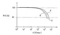
도 2 및 도 3은 발광다이오드의 열화를 설명하기 위한 도면이고,2 and 3 are views for explaining the deterioration of the light emitting diodes,
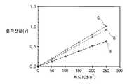
도 4a 및 도 4b는 광센서를 설명하기 위한 도면이고,4A and 4B are views for explaining an optical sensor,
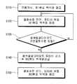
도 5는 본 발명의 제1실시예에 따른 구동방법을 나타낸 순서도이고,5 is a flowchart showing a driving method according to the first embodiment of the present invention;
도 6은 본 발명의 제1실시예에 따른 구동방법을 설명하기 위한 도면이고,6 is a view for explaining a driving method according to a first embodiment of the present invention;
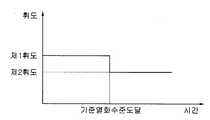
도 7은 본 발명의 제1실시예에 따른 구동방법에서 시간에 따른 휘도를 나타낸 도면이고,7 is a view showing luminance over time in the driving method according to the first embodiment of the present invention;
도 8은 본 발명의 제2실시예에 따른 구동방법을 나타낸 순서도이고,8 is a flowchart illustrating a driving method according to a second embodiment of the present invention.
도 9는 본 발명의 제2실시예에 따른 구동방법을 설명하기 위한 도면이고,9 is a view for explaining a driving method according to a second embodiment of the present invention;
도 10은 본 발명의 제3실시예에 따른 구동방법을 설명하기 위한 순서도이고,10 is a flowchart illustrating a driving method according to a third embodiment of the present invention.
도 11은 본 발명의 제4실시예에 따른 구동방법을 설명하기 위한 도면이고,11 is a view for explaining a driving method according to a fourth embodiment of the present invention;
도 12 및 도 13은 각각 본 발명의 제5실시예 및 제6실시예에 따른 구동방법에서 시간에 따른 휘도를 나타낸 도면이다.12 and 13 are views showing luminance over time in the driving method according to the fifth and sixth embodiments of the present invention, respectively.
* 도면의 주요부분의 부호에 대한 설명 *Explanation of Signs of Major Parts of Drawings
10 : 액정표시패널 20 : 백라이트 유닛10 liquid
210 : 광원부 211 : 발광다이오드210: light source 211: light emitting diode
220 : 전원공급부 230 : 광센서220: power supply 230: optical sensor
240 : 광원제어부240: light source control unit
본 발명은 액정표시장치와 액정표시장치의 구동방법에 관한 것이다.The present invention relates to a liquid crystal display device and a method of driving the liquid crystal display device.
액정표시장치는 액정표시패널과 백라이트 유닛을 포함한다. 액정표시패널은 박막트랜지스터 기판, 대향 기판 및 이들 기판 사이에 위치하는 액정층을 포함한다. 액정표시패널은 비발광소자이기 때문에 박막트랜지스터 기판의 후면에 위치하는 백라이트 유닛으로부터 빛을 공급받는다. 백라이트 유닛에서 조사된 빛은 액정의 배열상태에 따라 투과량이 조정된다.The liquid crystal display device includes a liquid crystal display panel and a backlight unit. The liquid crystal display panel includes a thin film transistor substrate, an opposing substrate, and a liquid crystal layer positioned between the substrates. Since the liquid crystal display panel is a non-light emitting device, light is supplied from the backlight unit positioned on the rear surface of the thin film transistor substrate. Light transmitted from the backlight unit is adjusted according to the arrangement of liquid crystals.
백라이트 유닛의 광원으로서 램프와 같은 선광원이 아닌 발광 다이오드(light emitting diode)와 같은 점광원이 주목받고 있다. 발광 다이오드는 통상 적색 발광다이오드, 녹색 발광다이오드 및 청색 발광다이오드가 같이 사용되며, 각 발광다이오드에서 발생한 빛은 믹싱을 통해 백색광이 된다.As a light source of the backlight unit, a spot light source such as a light emitting diode is drawing attention instead of a line light source such as a lamp. In the light emitting diode, a red light emitting diode, a green light emitting diode, and a blue light emitting diode are commonly used together, and the light generated from each light emitting diode becomes white light through mixing.
한편, 백라이트 유닛은 일정한 수명이 요구되는데, 발광 다이오드는 구동에 따라 열화되어 요구되는 수명을 만족시키기 어려운 문제가 있다.On the other hand, the backlight unit is required a certain life, the light emitting diode is deteriorated by the driving has a problem that is difficult to meet the required life.
본 발명의 목적은 광원부의 수명이 증가된 액정표시장치를 제공하는 것이다.It is an object of the present invention to provide a liquid crystal display device having an increased lifetime of the light source unit.
본 발명의 다른 목적은 광원부의 수명이 증가되는 액정표시장치의 구동방법을 제공하는 것이다.Another object of the present invention is to provide a method of driving a liquid crystal display device, in which the life of the light source unit is increased.
상기 본 발명의 목적은 액정표시패널과, 상기 액정표시패널의 후방에 위치하는 백라이트 유닛을 포함하는 액정표시장치에 있어서, 상기 백라이트 유닛은, 복수의 점광원을 포함하는 광원부와; 상기 광원부에 전원을 공급하는 전원공급부와; 상기 광원부의 열화수준을 판단하고, 판단된 열화수준이 기준열화수준이 되면 상기 광원부가 현재의 제1휘도보다 낮은 제2휘도의 빛을 공급하도록 상기 전원공급부를 제어하는 광원제어부를 포함하는 것에 의하여 달성된다.An object of the present invention is a liquid crystal display device comprising a liquid crystal display panel and a backlight unit positioned behind the liquid crystal display panel, wherein the backlight unit comprises: a light source unit including a plurality of point light sources; A power supply unit supplying power to the light source unit; And determining a deterioration level of the light source unit and including a light source control unit controlling the power supply unit to supply light having a second luminance lower than a current first luminance when the determined deterioration level becomes a reference deterioration level. Is achieved.
상기 점광원은 서로 다른 색상의 빛을 발광하는 복수의 발광 다이오드를 포함하는 것이 바람직하다.The point light source preferably includes a plurality of light emitting diodes emitting light of different colors.
상기 백라이트 유닛은, 상기 광원부가 공급하는 빛의 특성을 측정하는 광센서를 더 포함하는 것이 바람직하다.The backlight unit may further include an optical sensor for measuring characteristics of light supplied from the light source unit.
상기 전원공급부는 상기 각 발광다이오드 별로 전원을 공급하며, 상기 광원제어부는 상기 광원부가 백색광을 상기 액정표시패널에 공급하도록 상기 전원공급부를 제어하는 것이 바람직하다.The power supply unit supplies power to each of the light emitting diodes, and the light source control unit controls the power supply unit to supply the white light to the liquid crystal display panel.
상기 광원제어부는 상기 열화수준을 상기 광원부의 구동시간을 기준으로 판 단하는 것이 바람직하다.Preferably, the light source controller determines the deterioration level based on the driving time of the light source unit.
상기 광센서가 측정하는 빛의 특성은 휘도를 포함하며, 상기 광원제어부는 상기 열화수준을 상기 광원부의 휘도와 상기 광원부에 공급되는 전원레벨에 기초하여 판단하는 것이 바람직하다.The characteristic of light measured by the optical sensor includes luminance, and the light source controller determines the deterioration level based on the luminance of the light source unit and the power level supplied to the light source unit.
상기 광센서는 상기 각 발광다이오드의 광특성을 측정하며, 상기 광원제어부는 상기 열화수준을 상기 각 발광다이오드에 대하여 판단하는 것이 바람직하다.The optical sensor may measure optical characteristics of each of the light emitting diodes, and the light source controller may determine the deterioration level with respect to each of the light emitting diodes.
상기 기준열화수준은 상기 복수의 발광다이오드 중 어느 하나에 대하여 설정되어 있는 것이 바람직하다.Preferably, the reference degradation level is set for any one of the plurality of light emitting diodes.
상기 전원공급부는 펄스폭 변조방식(PWM)으로 상기 광원부에 전원을 공급하는 것이 바람직하다.Preferably, the power supply unit supplies power to the light source unit using a pulse width modulation method (PWM).
상기 광원제어부는 상기 열화수준을 전원의 듀티비(duty ratio)를 기준으로 판단하는 것이 바람직하다.Preferably, the light source controller determines the deterioration level based on a duty ratio of a power source.
상기 본 발명의 다른 목적은 액정표시패널과, 상기 액정표시패널의 배면에 위치하며 서로 다른 색을 발광하는 복수의 발광다이오드를 포함하는 광원부를 포함하는 액정표시장치의 구동방법에 있어서, 상기 광원부에 전원을 공급하여 상기 액정표시패널에 제1휘도의 백색광을 공급하는 단계와; 상기 광원부의 열화수준을 판단하는 단계와; 상기 광원부의 열화수준이 기준열화수준이 되면 상기 액정표시패널에 상기 제1휘도보다 낮은 제2휘도의 백색광을 공급하는 단계를 포함하는 것에 의해 달성된다.According to another aspect of the present invention, there is provided a liquid crystal display panel and a light source unit including a plurality of light emitting diodes disposed on a rear surface of the liquid crystal display panel and emitting different colors. Supplying power to supply white light having a first luminance to the liquid crystal display panel; Determining a deterioration level of the light source unit; And when the deterioration level of the light source unit reaches a reference deterioration level, supplying white light having a second luminance lower than the first luminance to the liquid crystal display panel.
상기 열화수준은 상기 광원부의 구동시간을 기준으로 판단하는 것이 바람직 하다.The deterioration level is preferably determined based on the driving time of the light source unit.
상기 열화수준은 상기 광원부의 휘도와 상기 광원부에 공급되는 전원레벨에 기초하여 판단하는 것이 바람직하다.The deterioration level is preferably determined based on the brightness of the light source unit and the power level supplied to the light source unit.
상기 전원은 펄스폭 변조방식(PWM)으로 공급되는 것이 바람직하다.The power is preferably supplied in a pulse width modulation scheme (PWM).
상기 열화수준은 전원의 듀티비(duty ratio)를 기준으로 판단되는 것이 바람직하다.The deterioration level is preferably determined based on the duty ratio of the power source.
상기 본 발명의 다른 목적은 액정표시패널과, 상기 액정표시패널에 빛을 공급하며 서로 다른 색을 발광하는 복수의 발광다이오드를 포함하는 광원부를 포함하는 액정표시장치의 구동방법에 있어서, 상기 각 발광다이오드 별로 전원을 공급하여 상기 액정표시패널에 제1휘도의 백색광을 공급하는 단계와; 상기 각 발광다이오드의 열화수준을 판단하는 단계와; 상기 각 발광다이오드의 열화수준에 따라 상기 각 발광다이오드에 공급되는 전원레벨을 조절하면서 상기 제1휘도의 백색광을 공급하는 단계와; 상기 각 발광다이오드 중 어느 하나의 열화수준이 기준열화수준이 되면, 상기 액정표시패널에 상기 제1휘도보다 낮은 제2휘도의 백색광을 공급하는 단계를 포함하는 것에 의해서도 달성된다.According to another aspect of the present invention, there is provided a liquid crystal display panel and a light source unit including a plurality of light emitting diodes which supply light to the liquid crystal display panel and emit light of different colors, wherein each of the light emitting devices includes: Supplying power for each diode to supply white light having a first luminance to the liquid crystal display panel; Determining a deterioration level of each of the light emitting diodes; Supplying white light having the first luminance while adjusting a power level supplied to each light emitting diode according to a deterioration level of each light emitting diode; When the deterioration level of any one of the light emitting diodes is the reference deterioration level, it is also achieved by supplying the white light having a second luminance lower than the first luminance to the liquid crystal display panel.
이하 첨부된 도면을 참조로 하여 본 발명을 더욱 상세히 설명하겠다.Hereinafter, the present invention will be described in more detail with reference to the accompanying drawings.
이하의 실시예에서는 점광원으로서 발광 다이오드를 예로 들어 설명하나, 본 발명의 점광원은 발광 다이오드에 한정되지 않는다.In the following embodiments, a light emitting diode is described as an example of a point light source, but the point light source of the present invention is not limited to the light emitting diode.
본발명의 일실시예에 따른 액정표시장치를 도1을 참조하여 설명한다.A liquid crystal display according to an embodiment of the present invention will be described with reference to FIG.
액정표시장치(1)는 액정표시패널(10)과 백라이트 유닛(20)을 포함한다. 액정표시패널(10)은 백라이트 유닛(20)에서 공급된 빛의 투과량을 조절한다.The liquid crystal display device 1 includes a liquid
백라이트 유닛(20)은 빛을 생성하는 광원부(210), 광원부(210)에 전원을 공급하는 전원공급부(220), 광원부(210)에서 생성한 빛의 특성을 감지하는 광센서(230), 광센서(230)가 감지한 결과에 기초하여 전원공급부(220)를 제어하는 광원제어부(240)를 포함한다.The
광원부(210)에는 발광다이오드(211)가 마련되어 있다. 발광다이오드(211)는 적색 발광다이오드(211r), 녹색 발광다이오드(211g) 및 청색 발광다이오드(211b)를 포함한다. 발광다이오드(211)에서 발생한 빛은 액정표시패널(10)에 공급되는데, 3가지 색상의 빛이 믹싱된 백색광이 액정표시패널(10)에 공급된다. 도시하지는 않았지만 광원부(210)는 발광다이오드(211)가 장착되는 회로기판을 더 포함한다.The
발광다이오드(211)는 구동시간에 따라 열화된다. 즉 상온에서 동일한 전류를 공급할 경우 구동시간에 따라 휘도가 감소한다. 통상 동일한 레벨의 전류에서 초기 휘도의 50%가 되는 시간을 발광다이오드(211)의 수명으로 본다.The
도 2를 보면, 발광다이오드(211)는 통상 수만 시간의 수명을 가지며, 청색 발광다이오드(211b)의 수명이 가장 짧은 것을 알 수 있다.Referring to FIG. 2, the
발광다이오드(211)의 수명은 온도에 의해서도 영향을 받는데, 도 3을 보면, 온도가 증가함에 따라 수명이 급격히 감소함을 알 수 있다. 이 경우에도 청색 발광다이오드(211b)의 수명이 가장 짧다. 한편, 이하의 실시예에서는 청색발광다이오드(211b)의 수명이 가장 짧은 것으로 예시되나, 본 발명은 이에 한정되지 않는다.The lifetime of the
전원공급부(220)는 펄스폭 변조방식(PWM) 또는 직류방식으로 광원부(210)에 전원을 공급할 수 있다. 펄스폭 변조방식에서는 전류레벨을 일정하게 하고 듀티비를 조절하며, 직류방식에서는 전류레벨을 변화시킨다. The
전원공급부(220)는 발광다이오드(211) 별로 전원을 공급한다. 예를 들어 청색 발광다이오드(211b)에 적색 발광다이오드(211r) 보다 높은 전원레벨의 전원을 공급할 수 있는 것이다. 여기서 전원레벨은 펄스폭 변조방식에서는 전류레벨 그리고/또는 듀티비이며, 직류방식에서는 전류레벨을 의미한다. 전류레벨이 일정한 펄스폭 변조방식에서 전원레벨이 높다는 것은 듀티비가 크다는 것을 의미한다.The
광센서(230)는 각 발광다이오드(211)의 광 특성을 측정한다. 즉, 적색광, 녹색광, 청색광 각각에 대한 휘도를 측정하는 것이다. 광센서(230)는 적색광, 녹색광, 청색광의 색좌표를 측정할 수도 있다.The
도 4a와 도 4b는 서로 다른 방식의 광센서(230)가 발광다이오드(211)의 광특성을 측정하는 것을 설명하기 위한 도면이다. 도 4a및 도 4b를 보면 광센서는 휘도별로 다른 전압을 출력하며, 또한 각 색상에 대한 휘도를 구분할 수 있음을 알 수 있다. 도 4a에 따른 광센서(230)는 휘도가 증가함에 따라 낮은 전압을 출력하고, 도 4b에 따른 광센서(230)는 휘도가 증가함에 따라 높은 전압을 출력한다.4A and 4B are diagrams for describing an
광원제어부(240)는 광센서(230)에서 측정한 색상별 휘도 결과를 기초로 전원공급부(220)를 제어한다. 즉 광원제어부(240)는 광센서(230)의 측정결과에 기초하여, 광원부(210)가 원하는 휘도의 백색광을 공급하도록 전원공급부(220)를 제어한다. 예를 들어, 적색광이 부족하여 백색광이 얻어지지 않으면 적색발광다이오드(211r)의 전원레벨을 증가시키고, 백색광의 휘도가 낮으면 각 발광다이오드(211)의 전원레벨을 증가시킨다.The
앞서 언급한 바와 같이, 발광다이오드(211)는 구동에 따라 열화되어 동일한 전원레벨에서 휘도가 감소한다. 따라서 동일한 휘도의 백색광을 얻기 위해서는 전원레벨을 증가시켜야 한다. 펄스폭 변조방식에서는 휘도를 증가시키기 위해 통상 전류 레벨은 변화시키지 않고 듀티비를 증가시킨다. 전류 레벨을 변화시키면 빛의 특성이 달라지기 때문이다. 직류 방식에서는 휘도를 증가시키기 위해 전류 레벨을 증가시킨다.As mentioned above, the
그런데 열화가 더욱 진행되면 펄스폭 변조방식에서는 더 이상 듀티비를 올릴 수 없으며, 직류방식에서는 빛의 특성 변화 때문에 전류 레벨을 더 이상 증가시킬 수 없게 된다. 또한 전원 레벨을 증가시킴에 따라 발광다이오드(211)의 온도는 상승하여, 열화가 촉진된다. 따라서 광원부(210)의 수명이 저하되어 원하는 수명을 얻을 수 없다.However, when the degradation is further progressed, the duty ratio can no longer be increased in the pulse width modulation method, and in the DC method, the current level can no longer be increased due to the change in the light characteristics. In addition, as the power supply level is increased, the temperature of the
본 발명에 따른 광원제어부(240)는 광원부(210)의 열화수준이 기준 열화수준이 되면 전류레벨을 감소시켜 광원부(210)의 수명을 증가시킨다. 전류레벨이 감소함에 따라 휘도는 감소한다. 이를 이하의 실시예를 통해 상세히 설명한다.The light
도 5 내지 도 7을 참조하여 제1실시예에 따른 구동방법을 설명한다. 제1실시예에서 전원공급부(220)은 펄스폭 변조 방식으로 광원부(210)에 전원을 공급하며, 기준열화수준은 청색발광다이오드(211b)에 대하여 설정되어 있다.A driving method according to the first embodiment will be described with reference to FIGS. 5 to 7. In the first embodiment, the
먼저, 광원부(210)에 전원을 공급하여 액정표시패널(10)에 제1휘도의 백색광을 공급한다(S110). 도 6의 (a)를 보면 이 단계에서는 각 발광다이오드(211)의 듀티비는 50%로 동일하다. 전류레벨(Ir, Ig, Ib)는 서로 다를 수 있다. 다른 실시예에서는 초기 단계에서 각 발광다이오드(211)의 듀티비는 서로 다를 수 있다.First, power is supplied to the
다음으로 광원부(210)의 열화수준을 판단하고, 열화수준에 따라 듀티비를 보정하여 제1휘도의 백색광을 계속하여 공급한다(S120). 도 6의 (b)를 보면 듀티비는 각 발광다이오드(211) 모두에 대하여 증가한다. 실시예에서 청색 발광다이오드(211b)가 열화가 가장 심하며, 듀티비 증가 역시 가장 크다.Next, the deterioration level of the
이 과정에서 광원제어부(240)는 각 발광다이오드(211)의 열화수준을 판단한다. 광원제어부(240)는 증가한 듀티비를 기초로 각 발광다이오드(211)의 열화수준을 판단할 수 있다.In this process, the
제1휘도의 백색광을 공급하면서, 광원제어부(240)는 청색 발광다이오드(211b)의 열화수준이 기준열화수준에 도달하였는지 판단한다(S130). 통상 청색 발광다이오드(211b)가 다른 발광 다이오드(211r, 212g)에 비해 더 빨리 열화되므로, 제1실시예에서는 청색 발광다이오드(211b)를 광원부(210) 열화의 판단대상으로 한다.While supplying the white light having the first luminance, the
제1실시예에서 기준열화수준은 80%듀티비로 설정되어 있다. 도 6의 (c)를 보면 청색발광다이오드(211b)에 공급되는 전원의 듀티비가 80%에 도달했음을 알 수 있다. 이 때 다른 발광다이오드(211r, 211g)의 듀티비는 80%이하이다.In the first embodiment, the reference deterioration level is set to 80% duty ratio. Referring to FIG. 6C, it can be seen that the duty ratio of the power supplied to the blue light emitting diode 211b has reached 80%. At this time, the duty ratio of the other
다른 실시예에서 기준열화수준은 현재 듀티비/초기 듀티비의 비로 설정(예를 들어, 현재 듀티비/초기 듀티비가 1.3)되거나, 듀티비의 증가속도(예를 들어 100시간당 듀티비가 0.1%이상 증가) 등으로 설정될 수 있다.In another embodiment, the reference degradation level is set as the ratio of the current duty ratio / initial duty ratio (eg, the current duty ratio / initial duty ratio is 1.3), or the rate of increase of the duty ratio (eg, the duty ratio per 100 hours is 0.1% or more). Increase).
청색 발광다이오드(211b)의 열화수준이 기준열화수준에 도달하면, 즉 청색 발광다이오드(211b)에 공급되는 전원의 듀티비가 80%에 도달하면, 청색 발광다이오드(211b)에 공급되는 전원의 듀티비를 감소시킨다(S140).When the deterioration level of the blue light emitting diode 211b reaches the reference deterioration level, that is, when the duty ratio of the power supplied to the blue light emitting diode 211b reaches 80%, the duty ratio of the power supplied to the blue light emitting diode 211b is obtained. Reduce (S140).
도 6의 (d)를 보면 청색 발광다이오드(211b)에 공급되는 전원의 듀티비는 초기값인 50%로 감소된다. 다른 실시예에서, 감소된 전원의 듀티비는 초기값과 다른 값, 예를 들어 기준열화수준에 도달했을 때 듀티비의 70% 등으로 정해질 수 있다.Referring to FIG. 6D, the duty ratio of the power supplied to the blue light emitting diode 211b is reduced to 50%, which is an initial value. In another embodiment, the reduced power duty ratio may be set to a value different from the initial value, such as 70% of the duty ratio when the reference degradation level is reached.
이와 함께 백색광을 공급하기 위해 다른 발광다이오드(211r, 211g)의 듀티비도 조절된다. 다른 발광다이오드(211r, 211g)는 청색 발광다이오드(211b)에 비해 열화 정도가 약하기 때문에, 다른 발광다이오드(211r, 211g)의 듀티비는 청색 발광다이오드(211b)의 듀티비에 비하여 작게 된다.In addition, the duty ratio of the other
듀티비가 감소된 후의 제2휘도는 제1휘도보다 낮게 된다. 이는 청색 발광다이오드(211b)에 공급되는 전원의 듀티비는 구동초기와 동일하지만, 청색 발광다이오드(211b)는 이미 상당히 열화가 진행되었기 때문이다.The second luminance after the duty ratio is reduced becomes lower than the first luminance. This is because the duty ratio of the power supplied to the blue light emitting diode 211b is the same as the initial driving time, but the blue light emitting diode 211b has already undergone considerable deterioration.
다음으로 광원부(210)의 열화수준을 판단하고, 열화수준에 따라 듀티비를 보정하여 제2휘도의 백색광을 계속하여 공급한다(S150). 도 6의 (e)를 보면 광원부(210)의 열화에 따라 다시 모든 발광다이오드(211)의 듀티비가 증가하였음을 알 수 있다. 이 과정은 앞에서 설명한 바와 같기 때문에 반복 설명은 생략한다.Next, the deterioration level of the
이상 설명한 제1실시예에 따르면 도 7과 같이, 청색발광다이오드(211b)에 공급되는 전원의 듀티비가 80%가 되기까지, 즉 청색발광다이오드(211b)의 열화수준이 기준열화수준에 도달하기까지는 제1휘도의 백색광이 공급된다. 이후 청색발광다이오드(211b)에 공급되는 전원의 듀티비가 80%가 된 후, 즉 청색발광다이오드(211b)의 열화수준이 기준열화수준에 도달한 후에는 듀티비 감소가 이루어져 제1휘도보다 낮은 제2휘도의 백색광이 공급된다.According to the first embodiment described above, as shown in FIG. 7, until the duty ratio of the power supplied to the blue light emitting diode 211b becomes 80%, that is, until the deterioration level of the blue light emitting diode 211b reaches the reference degradation level. White light of the first luminance is supplied. After the duty ratio of the power supplied to the blue light emitting diode 211b reaches 80%, that is, after the degradation level of the blue light emitting diode 211b reaches the reference degradation level, the duty ratio decreases to lower the first luminance. White light of two luminance is supplied.
제1실시예에 따르면, 발광다이오드(211), 특히 청색발광다이오드(211b)가 과도하게 열화되는 것을 방지하여 광원부(210)의 수명을 증가시킬 수 있다.According to the first embodiment, the lifespan of the
한편 제1실시예에서는 청색발광다이오드(211b)를 광원부(210) 열화판단의 기준으로 하였으나, 다른 실시예에서는 다른 발광다이오드(211r, 211g)를 열화판단의 대상으로 할 수 있다.Meanwhile, in the first embodiment, the blue light emitting diode 211b is used as a criterion for deterioration determination of the
도 8 및 도 9를 참조하여 제2실시예에 따른 구동방법을 설명하며, 제1실시예와 다른 부분을 중심으로 설명한다.A driving method according to the second embodiment will be described with reference to FIGS. 8 and 9, and will be described with reference to parts different from the first embodiment.
청색 발광다이오드(211b)의 열화수준이 기준열화수준에 도달한 경우, 즉 청색 발광다이오드(211b)에 공급되는 전원의 듀티비가 80%에 도달한 경우에, 각 발광다이오드(211)에 공급되는 전원의 듀티비는 제2휘도의 백색광을 공급하도록 조절된다. 제2휘도는 제1휘도보다 낮으며, 예를 들어, 제1휘도의 80%로 설정될 수 있다.When the deterioration level of the blue light emitting diodes 211b reaches the reference deterioration level, that is, when the duty ratio of the power supplied to the blue light emitting diodes 211b reaches 80%, the power supplied to each
도 9의 (d)를 보면 제2휘도의 백색광을 공급하기 위해 각 발광다이오드(211)에 공급되는 전원의 듀티비가 감소함을 알 수 있다. 이 때 열화가 심한 청색발광다이오드(211b)에 대한 전원의 듀티비가 다른 발광다이오드(211r, 211g)에 대한 전원의 듀티비보다 크게 된다.Referring to FIG. 9D, it can be seen that the duty ratio of the power supplied to each
제2실시예 역시 발광다이오드(211)의 과도한 열화를 방지하여 광원부(210)의 수명을 증가시킬 수 있다.The second embodiment may also increase the lifespan of the
도 10을 참조하여 제3실시예에 따른 구동방법을 설명하며, 제1실시예와 다른 부분을 중심으로 설명한다.A driving method according to the third embodiment will be described with reference to FIG. 10, and description will be mainly given with respect to parts different from the first embodiment.
기준열화수준은 각 발광다이오드(211)에 대하여 모두 설정되어 있다. 예를 들어, 적색 발광다이오드(211r)에는 듀티비 75%, 녹색 발광다이오드(211g)에는 듀티비 78%, 청색 발광다이오드(211b)에는 듀티비 80%가 기준열화수준으로 설정된다.The reference deterioration level is set for each
듀티비 감소는 발광다이오드(211) 중 어느 하나가 기준열화수준에 도달하면 이루어진다. 예를 들어, 위와 같이 기준열화수준이 설정된 경우 녹색 발광다이오드(211g)에 대한 듀티비가 77%, 청색 발광다이오드(211b)에 대한 듀티비가 78%일 때, 적색 발광다이오드(211r)에 대한 듀티비가 75%가 되면 듀티비 감소를 수행하는 것이다.The duty ratio is reduced when any one of the
제3실시예에 따르면 발광다이오드(211) 중 어느 하나의 예상치 못한 급격한 열화에 적절히 대응할 수 있다.According to the third embodiment, it is possible to appropriately cope with unexpected sudden deterioration of any one of the
다른 실시예에서는 모든 발광다이오드(211)가 각자의 기준열화수준에 도달한 경우 듀티비 조절을 수행할 수 있다. 또 다른 실시예에서는 각 발광다이오드(211)의 기준열화수준이 동일하게, 예를 들어 듀티비 80%로 설정될 수 있다.In another embodiment, when all of the
도 11을 참조하여 제4실시예에 따른 구동방법을 설명하며, 제1실시예와 다른 부분을 중심으로 설명한다. 제4실시예에서 기준열화수준은 제1실시예와 같이 청색 발광다이오드(211b)에 대하여 설정되어 있다.A driving method according to the fourth embodiment will be described with reference to FIG. 11, and description will be mainly given with respect to parts different from the first embodiment. In the fourth embodiment, the reference deterioration level is set for the blue light emitting diode 211b as in the first embodiment.
광원부(210)에는 직류 방식으로 전원이 공급된다. 도 11의 (a)를 보면 초기 단계에서 각 발광다이오드(211)에 공급되는 전류 레벨은 100mA로 동일하다. 다른 실시예에서는 초기 단계에서 각 발광다이오드(211)의 듀티비는 서로 다를 수 있다.The
이 후 도 11의 (b)와 같이 발광다이오드(211)의 열화가 진행됨에 따라 각 발광다이오드(211)에 공급되는 전류 레벨이 증가한다. 특히 열화가 심한 청색 발광다이오드(211b)에 공급되는 전류 레벨이 크게 증가한다.Thereafter, as the
이후 도 11의 (c)와 같이 열화가 더 진행되어, 청색발광다이오드(211b)에 공급되는 전류레벨이 기준열화수준으로서 설정한 115mA에 도달한다.Subsequently, deterioration further proceeds as shown in FIG. 11C, and the current level supplied to the blue light emitting diode 211b reaches 115 mA set as the reference deterioration level.
청색발광다이오드(211b)의 열화수준이 기준열화수준에 도달하면, 도 11의 (d)와 같이 청색발광다이오드(211b)에 공급되는 전류레벨을 초기값인 100mA로 감소시킨다. 이와 함께 백색광을 공급하기 위해 다른 발광다이오드(211r, 211g)에 대한 전류레벨도 감소된다. 다른 발광다이오드(211r, 211g)는 청색 발광다이오드(211b)에 비해 열화 정도가 약하기 때문에, 다른 발광다이오드(211r, 211g)의 전류레벨은 청색 발광다이오드(211b)의 전류레벨에 비하여 작게 된다.When the deterioration level of the blue light emitting diode 211b reaches the reference deterioration level, the current level supplied to the blue light emitting diode 211b is reduced to an initial value of 100 mA as shown in FIG. Along with this, the current levels for the other
전류레벨이 감소된 후의 제2휘도는 제1휘도보다 낮게 된다. 이는 청색 발광다이오드(211b)에 공급되는 전원의 전류레벨은 같지만, 청색 발광다이오드(211b)는 이미 상당히 열화가 진행되었기 때문이다.The second luminance after the current level is reduced becomes lower than the first luminance. This is because the current level of the power supplied to the blue light emitting diode 211b is the same, but the blue light emitting diode 211b has already deteriorated considerably.
다음으로 광원부(210)의 열화수준을 판단하고, 열화수준에 따라 전류 레벨을 보정하여 제2휘도의 백색광을 계속하여 공급한다. 도 11의 (e)를 보면 광원부(210)의 열화에 따라 다시 모든 발광다이오드(211)의 전류레벨이 증가하였음을 알 수 있다.Next, the deterioration level of the
제4실시예에 따르면, 발광다이오드(211), 특히 청색발광다이오드(211b)가 과도하게 열화되는 것을 방지하여 광원부(210)의 수명을 증가시킬 수 있다. 또한 전류레벨이 변화되면 발광다이오드(211)에서 발생하는 빛의 특성이 변화되어 백색광을 공급하기 어려워진다. 제4실시예에 따르면 전류레벨이 급격히 변화되는 것을 방지하여, 광원부(210)가 백색광을 공급하기 용이해진다.According to the fourth embodiment, the lifespan of the
이상의 실시예에서는 발광다이오드(211)에 공급되는 전원레벨, 즉 동일한 휘도를 공급하기 위해 증가되는 전원레벨을 기준으로 발광다이오드(211)의 열화수준을 판단하였다. 발광다이오드(211)의 열화수준은 다른 방법으로 판단될 수 있는데 이를 제5실시예를 통해 설명한다.In the above embodiment, the degradation level of the
도 12는 제5실시예를 설명하기 위한 도면이다. 제5실시예에서는 기준열화수준을 광원부(210)의 구동시간을 기준으로 판단한다. 즉, 발광다이오드(211)의 열화정도는 구동시간에 비례하므로, 광원부(210)의 구동시간을 기준열화수준으로 설정하는 것이다. 광원제어부(240)는 구동시간을 카운트하기 위한 타이머를 더 포함한다.12 is a diagram for explaining a fifth embodiment. In the fifth embodiment, the reference degradation level is determined based on the driving time of the
기준열화수준인 기준시간은, 예를 들어, 목표수명의 50%로 설정될 수 있다. 따라서 목표수명이 4만 시간인 경우, 구동시간이 2만 시간에 도달하면, 발광다이오드(211)에 공급되는 전압레벨을 감소시키는 것이다. 이에 따라 휘도는 감소하게 된다. 기준시간은 실험 및 시뮬레이션을 통해 설정될 수 있으며, 발광다이오드(211)의 열화가 급격히 진행되기 직전의 시간으로 정해질 수 있다.The reference time, which is the reference deterioration level, may be set to 50% of the target life, for example. Therefore, when the target life is 40,000 hours, when the driving time reaches 20,000 hours, the voltage level supplied to the
다른 실시예에서는 발광다이오드(211)에 공급 및 출력되는 전류와 전압을 감지하여 발광다이오드(211)의 열화를 판단할 수 있다. 예를 들어 발광다이오드(211)가 열화될수록 발광다이오드(211)에서 출력되는 전류는 감소하므 로, 열화를 판단할 수 있다. 또한 출력되는 전류로부터 발광다이오드(211)의 휘도도 알 수 있다. 이 경우 광센서(230)는 사용하지 않을 수 있다.In another embodiment, deterioration of the
이상의 실시예에서는 발광다이오드(211)에 공급되는 전원의 전원레벨을 일회 감소시켰으나, 본 발명은 이에 한정되지 않으며 이를 제6실시예를 통해 설명한다.In the above embodiment, the power level of the power supplied to the
도 13은 제6실시예를 설명하기 위한 도면이다. 도 13을 보면 복수개의 기준열화수준이 마련되어 있다. 예를 들어 제1기준열화수준은 청색 발광다이오드(211b)에 대한 듀티비 75%, 제2기준열화수준은 청색 발광다이오드(211b)에 대한 듀티비 70%, 제3기준열화수준은 청색 발광다이오드(211b)에 대한 듀티비 65%로 설정될 수 있다.13 is a diagram for explaining a sixth embodiment. 13, a plurality of reference deterioration levels are provided. For example, the first reference degradation level is 75% of the duty ratio for the blue light emitting diode 211b, the second reference degradation level is 70% of the duty ratio for the blue light emitting diode 211b, and the third reference degradation level is the blue light emitting diode The duty ratio for 211b may be set to 65%.
제1휘도의 백색광을 공급하는 단계에서 제1기준열화수준에 도달하면 듀티비를 감소시켜 제2휘도의 백색광을 공급한다. 제2휘도의 백색광을 공급하는 단계에서도 발광다이오드(211)의 열화는 계속 진행되어 듀티비가 증가한다. 제2기준열화수준에 도달하면 다시 듀티비를 감소시켜 제3휘도의 백색광을 공급한다. 이후 제3기준열화수준에 도달하면 다시 듀티비를 감소시켜 제4휘도의 백색광을 공급한다. 이 때 동일한 휘도의 백색광을 공급하는 시간은 구동시간이 지남에 따라 짧아질 수 있다..When the first reference degradation level is reached in the step of supplying the white light having the first luminance, the duty ratio is reduced to supply the white light having the second luminance. Even in the step of supplying the white light having the second luminance, the degradation of the
제6실시예에 따르면 휘도변화의 급격한 변화를 막으면서 광원부(210)의 수명을 증가시킬 수 있다.According to the sixth embodiment, the lifespan of the
비록 본발명의 몇몇 실시예들이 도시되고 설명되었지만, 본발명이 속하는 기술분야의 통상의 지식을 가진 당업자라면 본발명의 원칙이나 정신에서 벗어나지 않으면서 본 실시예를 변형할 수 있음을 알 수 있을 것이다. 본발명의 범위는 첨부된 청구항과 그 균등물에 의해 정해질 것이다.Although some embodiments of the invention have been shown and described, those skilled in the art will recognize that modifications can be made to the embodiments without departing from the spirit or principles of the invention. . It is intended that the scope of the invention be defined by the claims appended hereto and their equivalents.
이상 설명한 바와 같이 본 발명에 따르면 광원부의 수명이 증가된 액정표시장치가 제공된다.As described above, according to the present invention, a liquid crystal display device having an increased lifespan of a light source unit is provided.
또한 본 발명에 따르면 광원부의 수명이 증가되는 액정표시장치의 구동방법이 제공된다.According to the present invention, there is provided a driving method of a liquid crystal display device in which the life of the light source unit is increased.
Claims (16)
Translated fromKoreanPriority Applications (2)
| Application Number | Priority Date | Filing Date | Title |
|---|---|---|---|
| KR1020060088543AKR20080024323A (en) | 2006-09-13 | 2006-09-13 | LCD and driving method of LCD |
| US11/854,473US20080062118A1 (en) | 2006-09-13 | 2007-09-12 | Backlight Unit and Driving Method of the Same |
Applications Claiming Priority (1)
| Application Number | Priority Date | Filing Date | Title |
|---|---|---|---|
| KR1020060088543AKR20080024323A (en) | 2006-09-13 | 2006-09-13 | LCD and driving method of LCD |
Publications (1)
| Publication Number | Publication Date |
|---|---|
| KR20080024323Atrue KR20080024323A (en) | 2008-03-18 |
Family
ID=39169087
Family Applications (1)
| Application Number | Title | Priority Date | Filing Date |
|---|---|---|---|
| KR1020060088543ACeasedKR20080024323A (en) | 2006-09-13 | 2006-09-13 | LCD and driving method of LCD |
Country Status (2)
| Country | Link |
|---|---|
| US (1) | US20080062118A1 (en) |
| KR (1) | KR20080024323A (en) |
Cited By (2)
| Publication number | Priority date | Publication date | Assignee | Title |
|---|---|---|---|---|
| WO2012144864A3 (en)* | 2011-04-20 | 2013-01-17 | 주식회사 이엠퍼스트 | Led lighting apparatus capable of protecting led elements, and method for controlling the led lighting apparatus |
| US8866727B2 (en) | 2008-12-02 | 2014-10-21 | Samsung Display Co., Ltd. | Method for driving a light source apparatus with varying luminance and a display apparatus having the light source apparatus |
Families Citing this family (5)
| Publication number | Priority date | Publication date | Assignee | Title |
|---|---|---|---|---|
| KR100714427B1 (en)* | 2005-10-12 | 2007-05-07 | 삼성전자주식회사 | Display device and control method |
| KR101441383B1 (en)* | 2007-12-03 | 2014-09-18 | 엘지디스플레이 주식회사 | Liquid crystal display and driving method thereof |
| US20090189841A1 (en)* | 2008-01-24 | 2009-07-30 | Himax Technologies Limited | Open-loop color management for light emitting diode backlight module |
| US8654068B2 (en)* | 2011-07-15 | 2014-02-18 | Apple Inc. | Enhanced resolution of luminance levels in a backlight unit of a display device |
| DE102016014652A1 (en)* | 2016-12-08 | 2018-06-14 | Inova Semiconductors Gmbh | Measuring arrangement for detecting aging processes of individual light-emitting diodes |
Family Cites Families (11)
| Publication number | Priority date | Publication date | Assignee | Title |
|---|---|---|---|---|
| US6611249B1 (en)* | 1998-07-22 | 2003-08-26 | Silicon Graphics, Inc. | System and method for providing a wide aspect ratio flat panel display monitor independent white-balance adjustment and gamma correction capabilities |
| US6157143A (en)* | 1999-03-02 | 2000-12-05 | General Electric Company | Fluroescent lamps at full front surface luminance for backlighting flat panel displays |
| US7262752B2 (en)* | 2001-01-16 | 2007-08-28 | Visteon Global Technologies, Inc. | Series led backlight control circuit |
| US7088334B2 (en)* | 2001-06-28 | 2006-08-08 | Matsushita Electric Industrial Co., Ltd. | Liquid crystal display device and manufacturing method thereof, and drive control method of lighting unit |
| US7391475B2 (en)* | 2002-01-31 | 2008-06-24 | Hewlett-Packard Development Company, L.P. | Display image generation with differential illumination |
| AU2005224841A1 (en)* | 2004-03-15 | 2005-09-29 | Aerospace Optics, Inc. | Programmable dichromatic legend lighted switches |
| US20060158397A1 (en)* | 2005-01-14 | 2006-07-20 | Joon-Chul Goh | Display device and driving method therefor |
| US7414862B2 (en)* | 2005-03-21 | 2008-08-19 | Chan Woong Park | Method and apparatus for regulating an output current from a power converter |
| KR100674867B1 (en)* | 2005-05-18 | 2007-01-30 | 삼성전기주식회사 | DC-DC converter with overcurrent / overvoltage protection and LED drive circuit |
| CN101292574B (en)* | 2005-08-17 | 2012-12-26 | 皇家飞利浦电子股份有限公司 | Digitally controlled luminaire system |
| US7557518B2 (en)* | 2006-01-24 | 2009-07-07 | Astronautics Corporation Of America | Solid-state, color-balanced backlight with wide illumination range |
- 2006
- 2006-09-13KRKR1020060088543Apatent/KR20080024323A/ennot_activeCeased
- 2007
- 2007-09-12USUS11/854,473patent/US20080062118A1/ennot_activeAbandoned
Cited By (2)
| Publication number | Priority date | Publication date | Assignee | Title |
|---|---|---|---|---|
| US8866727B2 (en) | 2008-12-02 | 2014-10-21 | Samsung Display Co., Ltd. | Method for driving a light source apparatus with varying luminance and a display apparatus having the light source apparatus |
| WO2012144864A3 (en)* | 2011-04-20 | 2013-01-17 | 주식회사 이엠퍼스트 | Led lighting apparatus capable of protecting led elements, and method for controlling the led lighting apparatus |
Also Published As
| Publication number | Publication date |
|---|---|
| US20080062118A1 (en) | 2008-03-13 |
Similar Documents
| Publication | Publication Date | Title |
|---|---|---|
| US8013533B2 (en) | Method and driver for determining drive values for driving a lighting device | |
| US8035603B2 (en) | Illumination system and liquid crystal display | |
| KR101370339B1 (en) | Back Light Apparatus And Control Method Thereof | |
| KR101010555B1 (en) | Light source unit for use in lighting devices | |
| US7518319B2 (en) | LED lighting device and LCD device using the same | |
| US7671542B2 (en) | Color control of multi-zone LED backlight | |
| JP5281236B2 (en) | LED light source for backlighting with integrated electronics | |
| RU2496155C2 (en) | Power control method for light-emitting device for image display, light-emitting device for image display, display device and television receiver | |
| EP1950730B1 (en) | Backlight and liquid crystal display using the same | |
| US8648791B2 (en) | Backlight module and method of determining driving current thereof | |
| US8259097B2 (en) | Backlight assembly, display comprising the same and control method thereof | |
| CN100440299C (en) | image display device | |
| JP4882657B2 (en) | Backlight control device, backlight control method, and liquid crystal display device | |
| JP2007123279A (en) | Driving device for backlight, backlight assembly, liquid crystal display device having the same, and driving method for backlight | |
| CN104913239B (en) | Planar illuminating device and liquid crystal display device | |
| KR20090035286A (en) | Back light assembly and display device having same | |
| KR20080079046A (en) | Backlight unit, LCD including same and control method thereof | |
| JP2008268642A (en) | Backlight device, method for controlling backlight and liquid crystal display device | |
| KR20080024323A (en) | LCD and driving method of LCD | |
| JP2014220200A (en) | Illuminating device and control method thereof | |
| US8284348B2 (en) | Backlight apparatus and liquid crystal display apparatus | |
| JP7401332B2 (en) | liquid crystal display device | |
| JP4245495B2 (en) | Rear light source for display device and display device | |
| KR20080034294A (en) | Backlight unit and liquid crystal display including the same | |
| KR101723621B1 (en) | EL controle divice capable of keeping luminance constant and method thereof |
Legal Events
| Date | Code | Title | Description |
|---|---|---|---|
| PA0109 | Patent application | Patent event code:PA01091R01D Comment text:Patent Application Patent event date:20060913 | |
| PG1501 | Laying open of application | ||
| A201 | Request for examination | ||
| PA0201 | Request for examination | Patent event code:PA02012R01D Patent event date:20110909 Comment text:Request for Examination of Application Patent event code:PA02011R01I Patent event date:20060913 Comment text:Patent Application | |
| N231 | Notification of change of applicant | ||
| PN2301 | Change of applicant | Patent event date:20120913 Comment text:Notification of Change of Applicant Patent event code:PN23011R01D | |
| E902 | Notification of reason for refusal | ||
| PE0902 | Notice of grounds for rejection | Comment text:Notification of reason for refusal Patent event date:20120921 Patent event code:PE09021S01D | |
| E601 | Decision to refuse application | ||
| PE0601 | Decision on rejection of patent | Patent event date:20121221 Comment text:Decision to Refuse Application Patent event code:PE06012S01D Patent event date:20120921 Comment text:Notification of reason for refusal Patent event code:PE06011S01I |