KR20080019808A - Organic thin film deposition apparatus and method - Google Patents
Organic thin film deposition apparatus and methodDownload PDFInfo
- Publication number
- KR20080019808A KR20080019808AKR1020060082187AKR20060082187AKR20080019808AKR 20080019808 AKR20080019808 AKR 20080019808AKR 1020060082187 AKR1020060082187 AKR 1020060082187AKR 20060082187 AKR20060082187 AKR 20060082187AKR 20080019808 AKR20080019808 AKR 20080019808A
- Authority
- KR
- South Korea
- Prior art keywords
- raw material
- organic
- impurity
- thin film
- unit
- Prior art date
- Legal status (The legal status is an assumption and is not a legal conclusion. Google has not performed a legal analysis and makes no representation as to the accuracy of the status listed.)
- Ceased
Links
- 238000000034methodMethods0.000titleclaimsabstractdescription31
- 238000000427thin-film depositionMethods0.000titleclaimsabstractdescription28
- 239000002994raw materialSubstances0.000claimsabstractdescription244
- 239000012535impuritySubstances0.000claimsabstractdescription180
- 238000000151depositionMethods0.000claimsabstractdescription71
- 230000008021depositionEffects0.000claimsabstractdescription71
- 238000002347injectionMethods0.000claimsabstractdescription63
- 239000007924injectionSubstances0.000claimsabstractdescription63
- 239000000758substrateSubstances0.000claimsabstractdescription56
- 239000000843powderSubstances0.000claimsabstractdescription43
- 230000008016vaporizationEffects0.000claimsabstractdescription12
- 239000012159carrier gasSubstances0.000claimsdescription53
- 238000003860storageMethods0.000claimsdescription39
- 238000012546transferMethods0.000claimsdescription34
- 238000005507sprayingMethods0.000claimsdescription20
- 238000010438heat treatmentMethods0.000claimsdescription19
- 238000007736thin film deposition techniqueMethods0.000claimsdescription6
- 238000001704evaporationMethods0.000claimsdescription4
- 239000000203mixtureSubstances0.000claimsdescription4
- 230000008020evaporationEffects0.000claimsdescription3
- 239000010409thin filmSubstances0.000abstractdescription37
- 238000004519manufacturing processMethods0.000abstractdescription3
- 239000011368organic materialSubstances0.000abstractdescription3
- 239000000463materialSubstances0.000description52
- 230000001276controlling effectEffects0.000description11
- 238000010586diagramMethods0.000description7
- 238000012937correctionMethods0.000description4
- 238000007789sealingMethods0.000description4
- 238000012986modificationMethods0.000description3
- 230000004048modificationEffects0.000description3
- 229920000642polymerPolymers0.000description2
- 239000002243precursorSubstances0.000description2
- 239000010453quartzSubstances0.000description2
- VYPSYNLAJGMNEJ-UHFFFAOYSA-Nsilicon dioxideInorganic materialsO=[Si]=OVYPSYNLAJGMNEJ-UHFFFAOYSA-N0.000description2
- 239000004952PolyamideSubstances0.000description1
- 239000004642PolyimideSubstances0.000description1
- 210000000746body regionAnatomy0.000description1
- 239000013078crystalSubstances0.000description1
- 238000005137deposition processMethods0.000description1
- 238000007599dischargingMethods0.000description1
- 239000002019doping agentSubstances0.000description1
- 239000010408filmSubstances0.000description1
- 239000011261inert gasSubstances0.000description1
- 239000011553magnetic fluidSubstances0.000description1
- 238000005259measurementMethods0.000description1
- 229920002647polyamidePolymers0.000description1
- 229920001721polyimidePolymers0.000description1
- 230000001105regulatory effectEffects0.000description1
- 239000004576sandSubstances0.000description1
- 230000035945sensitivityEffects0.000description1
- 239000007787solidSubstances0.000description1
- 238000007740vapor depositionMethods0.000description1
Images


Classifications
- C—CHEMISTRY; METALLURGY
- C23—COATING METALLIC MATERIAL; COATING MATERIAL WITH METALLIC MATERIAL; CHEMICAL SURFACE TREATMENT; DIFFUSION TREATMENT OF METALLIC MATERIAL; COATING BY VACUUM EVAPORATION, BY SPUTTERING, BY ION IMPLANTATION OR BY CHEMICAL VAPOUR DEPOSITION, IN GENERAL; INHIBITING CORROSION OF METALLIC MATERIAL OR INCRUSTATION IN GENERAL
- C23C—COATING METALLIC MATERIAL; COATING MATERIAL WITH METALLIC MATERIAL; SURFACE TREATMENT OF METALLIC MATERIAL BY DIFFUSION INTO THE SURFACE, BY CHEMICAL CONVERSION OR SUBSTITUTION; COATING BY VACUUM EVAPORATION, BY SPUTTERING, BY ION IMPLANTATION OR BY CHEMICAL VAPOUR DEPOSITION, IN GENERAL
- C23C14/00—Coating by vacuum evaporation, by sputtering or by ion implantation of the coating forming material
- C23C14/06—Coating by vacuum evaporation, by sputtering or by ion implantation of the coating forming material characterised by the coating material
- C23C14/12—Organic material
- C—CHEMISTRY; METALLURGY
- C23—COATING METALLIC MATERIAL; COATING MATERIAL WITH METALLIC MATERIAL; CHEMICAL SURFACE TREATMENT; DIFFUSION TREATMENT OF METALLIC MATERIAL; COATING BY VACUUM EVAPORATION, BY SPUTTERING, BY ION IMPLANTATION OR BY CHEMICAL VAPOUR DEPOSITION, IN GENERAL; INHIBITING CORROSION OF METALLIC MATERIAL OR INCRUSTATION IN GENERAL
- C23C—COATING METALLIC MATERIAL; COATING MATERIAL WITH METALLIC MATERIAL; SURFACE TREATMENT OF METALLIC MATERIAL BY DIFFUSION INTO THE SURFACE, BY CHEMICAL CONVERSION OR SUBSTITUTION; COATING BY VACUUM EVAPORATION, BY SPUTTERING, BY ION IMPLANTATION OR BY CHEMICAL VAPOUR DEPOSITION, IN GENERAL
- C23C14/00—Coating by vacuum evaporation, by sputtering or by ion implantation of the coating forming material
- C23C14/06—Coating by vacuum evaporation, by sputtering or by ion implantation of the coating forming material characterised by the coating material
- C23C14/10—Glass or silica
- C—CHEMISTRY; METALLURGY
- C23—COATING METALLIC MATERIAL; COATING MATERIAL WITH METALLIC MATERIAL; CHEMICAL SURFACE TREATMENT; DIFFUSION TREATMENT OF METALLIC MATERIAL; COATING BY VACUUM EVAPORATION, BY SPUTTERING, BY ION IMPLANTATION OR BY CHEMICAL VAPOUR DEPOSITION, IN GENERAL; INHIBITING CORROSION OF METALLIC MATERIAL OR INCRUSTATION IN GENERAL
- C23C—COATING METALLIC MATERIAL; COATING MATERIAL WITH METALLIC MATERIAL; SURFACE TREATMENT OF METALLIC MATERIAL BY DIFFUSION INTO THE SURFACE, BY CHEMICAL CONVERSION OR SUBSTITUTION; COATING BY VACUUM EVAPORATION, BY SPUTTERING, BY ION IMPLANTATION OR BY CHEMICAL VAPOUR DEPOSITION, IN GENERAL
- C23C14/00—Coating by vacuum evaporation, by sputtering or by ion implantation of the coating forming material
- C23C14/22—Coating by vacuum evaporation, by sputtering or by ion implantation of the coating forming material characterised by the process of coating
- C23C14/228—Gas flow assisted PVD deposition
- C—CHEMISTRY; METALLURGY
- C23—COATING METALLIC MATERIAL; COATING MATERIAL WITH METALLIC MATERIAL; CHEMICAL SURFACE TREATMENT; DIFFUSION TREATMENT OF METALLIC MATERIAL; COATING BY VACUUM EVAPORATION, BY SPUTTERING, BY ION IMPLANTATION OR BY CHEMICAL VAPOUR DEPOSITION, IN GENERAL; INHIBITING CORROSION OF METALLIC MATERIAL OR INCRUSTATION IN GENERAL
- C23C—COATING METALLIC MATERIAL; COATING MATERIAL WITH METALLIC MATERIAL; SURFACE TREATMENT OF METALLIC MATERIAL BY DIFFUSION INTO THE SURFACE, BY CHEMICAL CONVERSION OR SUBSTITUTION; COATING BY VACUUM EVAPORATION, BY SPUTTERING, BY ION IMPLANTATION OR BY CHEMICAL VAPOUR DEPOSITION, IN GENERAL
- C23C14/00—Coating by vacuum evaporation, by sputtering or by ion implantation of the coating forming material
- C23C14/22—Coating by vacuum evaporation, by sputtering or by ion implantation of the coating forming material characterised by the process of coating
- C23C14/24—Vacuum evaporation
- C23C14/246—Replenishment of source material
Landscapes
- Chemical & Material Sciences (AREA)
- Chemical Kinetics & Catalysis (AREA)
- Engineering & Computer Science (AREA)
- Materials Engineering (AREA)
- Mechanical Engineering (AREA)
- Metallurgy (AREA)
- Organic Chemistry (AREA)
- Physical Vapour Deposition (AREA)
- Chemical Vapour Deposition (AREA)
- Electroluminescent Light Sources (AREA)
Abstract
Translated fromKoreanDescription
Translated fromKorean도 1은 종래의 유기 박막 증착 장치의 개념도.1 is a conceptual diagram of a conventional organic thin film deposition apparatus.
도 2는 본 발명의 제 1 실시예에 따른 유기 박막 증착 장치의 단면 개면도.Fig. 2 is a sectional cross-sectional view of an organic thin film deposition apparatus according to the first embodiment of the present invention.
도 3은 제 1 실시예에 따른 증착원 공급 모듈의 개념도.3 is a conceptual diagram of a deposition source supply module according to a first embodiment;
도 4는 제 1 실시예의 변형예에 따른 증착원 공급 모듈의 개념도.4 is a conceptual diagram of a deposition source supply module according to a modification of the first embodiment.
도 5는 본 발명의 제 2 실시예에 따른 유기 박막 증착 장치의 단면 개념도.5 is a cross-sectional conceptual view of an organic thin film deposition apparatus according to a second embodiment of the present invention.
<도면의 주요 부분에 대한 부호의 설명><Explanation of symbols for the main parts of the drawings>
10, 100 : 챔버20, 113 : 기판10, 100:
30, 40 : 도가니110 : 기판 안치부30, 40: crucible 110: substrate mounting portion
120 : 분사부130 : 회전축120: injection unit 130: rotation axis
140 : 하우징220 : 유기 원료 물질 공급부140
230 : 불순물 원료 물질 공급부240 : 이송부230: impurity raw material supply unit 240: transfer unit
본 발명의 유기 박막 증착 장치 및 방법에 관한 것으로, 호스트 물질과 도판트 물질을 챔버 외측에서 공급하여 박막 균일도는 물론 도핑 균일도를 향상시킬 수 있는 유기 박막 증착 장치 및 방법에 관한 것이다.The present invention relates to an organic thin film deposition apparatus and method, and more particularly, to an organic thin film deposition apparatus and method capable of supplying a host material and a dopant material outside a chamber to improve thin film uniformity and doping uniformity.
일반적으로 유기 박막은 챔버 내에 마련된 증발원을 이용하여 유기 원료 물질을 증발시켜 증착하였다. 즉, 도가니 내부에 유기 원료 물질을 두고, 도가니를 가열하여 유기 원료 물질을 기화시켜 유기 박막을 증착하였다.In general, the organic thin film was deposited by evaporating the organic raw material using an evaporation source provided in the chamber. That is, an organic raw material was placed inside the crucible, and the crucible was heated to vaporize the organic raw material to deposit an organic thin film.
이러한 유기 박막내에 불순물 도핑층을 형성하기 위해서는 챔버 내에 유기 원료 물질과 불순물 원료 물질을 각기 담고 있는 두개의 도가니를 두고 이 두 도가니를 가열하여 유기 원료 물질과 불순물 원료 물질을 기화시켜 불순물을 함유하는 유기 박막을 기판상에 증착하였다.In order to form an impurity doping layer in the organic thin film, two crucibles each containing an organic raw material and an impurity raw material are placed in a chamber, and the two crucibles are heated to vaporize the organic raw material and the impurity raw material to contain organic impurities. A thin film was deposited on the substrate.
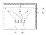
도 1은 종래의 유기 박막 증착 장치의 개념도이다.1 is a conceptual diagram of a conventional organic thin film deposition apparatus.
도 1을 참조하면, 종래의 유기 박막 증착 장치는 반응 챔버(10)와, 반응 챔버(10) 상측에 마련된 기판(20)과 상기 기판(20)의 하부에 배치되고 각기 유기 원료 물질과 불순물 원료 물질이 담길 제 1 및 제 2 도가니(30, 40)를 포함한다.Referring to FIG. 1, a conventional organic thin film deposition apparatus includes a
제 1 및 제 2 도가니(30, 40)에 각기 유기 원료 물질과 불순물 원료 물질을 넣은 다음 제 1 및 제 2 도가니(30, 40)를 가열하여 상기 유기 원료 물질과 불순물 원료 물질을 기화시켜 제 1 및 제 2 도가니(30, 40) 상측에 마련된 기판(20)상에 불순물 도핑된 유기 박막을 형성한다.Organic raw materials and impurity raw materials are put in the first and
이때, 불순물 도핑된 유기 박막의 경우 두가지 서로 다른 물질 각각의 성분량에 대하여 유기 원료 물질의 증착량과 불순물 원료 물질의 증착량을 수정 마이크로밸런스(Quartz Crystal Microbalance; QCM)를 이용하여 제어한다. 즉, 제 1 및 제 2 도가니(30, 40)로부터 기화되어 나온 유기 원료 물질과 불순물 원료 물질의 증기 흐름을 제 1 및 제 2 도가니(30, 40) 상측에 각기 마련된 수정 센서를 이용하여 측정한다. 그리고 그 측정 결과에 따라 증기 흐름을 제어하여 불순물 도핑된 유기 박막의 도핑 율(doping ratio)을 제어하였다.In this case, in the case of the impurity doped organic thin film, the deposition amount of the organic raw material and the deposition amount of the impurity raw material are controlled for each component amount of two different materials by using a quartz microbalance (QCM). That is, the vapor flows of the organic raw material and the impurity raw material vaporized from the first and
하지만, 유기 원료 물질과 불순물 원료 물질의 증기량을 수정 센서로 측정하고 그 결과를 이용하여 제어하기 때문에 수정 센서의 감도와 사용 수명에 크게 좌우된다. 이로인해 공정의 재현성 및 양산성이 저하되는 문제가 있다.However, since the amount of vapor of the organic raw material and the impurity raw material is measured by the correction sensor and controlled using the result, it greatly depends on the sensitivity and the service life of the correction sensor. This causes a problem that the reproducibility and mass productivity of the process are lowered.
또한, 유기 원료 물질과 불순물 원료 물질을 각기 다른 수정 센서로 측정하지만 이들을 공간적으로 완전히 분리시키지 못하게 된다. 유기 원료 물질의 증기 흐름을 측정하는 수정 센서와 불순물 원료 물질의 증기 흐름을 측정하는 수정 선세가 불순물 원료 물질의 증기 흐름과 유기 원료 물질의 증기 흐름에 서로 간섭을 받게 되는 문제가 발생한다. 그리고, 이러한 간섭없이 증착 공정을 진행하기 위해 챔버 내측에서의 센서 배치가 용이하지 않은 단점이 있다.In addition, organic raw materials and impurity raw materials are measured with different quartz sensors, but they do not completely separate them spatially. A problem arises in that a correction sensor for measuring the vapor flow of an organic raw material and a correction predecessor for measuring the vapor flow of an impurity raw material interfere with each other in the vapor flow of the impurity raw material and the vapor flow of the organic raw material. In addition, there is a disadvantage that the sensor arrangement inside the chamber is not easy to proceed the deposition process without such interference.
따라서, 본 발명은 상기의 문제점을 해결하기 위하여 챔버 외부에서 유기 원 료 물질 분말과 불순물 원료 물질 분말을 일정 비율로 혼합한 다음 챔버 내부로 공급하여 기판상에 형성되는 유기 박막 내의 불순물 량을 일정하게 제어할 수 있어 불순물 도핑된 유기 박막의 재현성을 향상시킬 수 있으며, 박막 두께의 균일도 및 도핑 균일도를 향상시킬 수 있는 유기 박막 증착 장치 및 방법을 제공하는 것을 그 목적으로 한다.Therefore, in order to solve the above problem, the present invention mixes the organic raw material powder and the impurity raw material powder in a predetermined ratio from the outside of the chamber, and then supplies them into the chamber to uniformly adjust the amount of impurities in the organic thin film formed on the substrate. It is an object of the present invention to provide an organic thin film deposition apparatus and method which can be controlled to improve reproducibility of an impurity doped organic thin film, and to improve uniformity and doping uniformity of thin film thickness.
본 발명에 따른 챔버와, 상기 챔버 내에 마련된 기판 안치 수단과, 유기 원료 물질 및 불순물 원료 물질을 기화시켜 분사하는 분사부와, 상기 분사부를 가열하는 가열 수단 및 상기 분사부에 상기 유기 원료 물질 및 불순물 원료 물질을 공급하는 증착원 공급 모듈을 포함하는 유기 박막 증착 장치를 제공한다.A chamber according to the present invention, a substrate placing means provided in the chamber, an injection unit for vaporizing and injecting an organic raw material and an impurity raw material, heating means for heating the injection unit, and the organic raw material and impurities in the injection unit An organic thin film deposition apparatus including a deposition source supply module for supplying a raw material is provided.
여기서, 상기 분사부는, 내부 공간을 갖는 몸체 및 상기 몸체에 마련된 복수의 노즐을 포함하고, 상기 가열 수단에 의해 상기 몸체의 내부 공간이 가열되는 것이 바람직하다.Here, it is preferable that the injection unit includes a body having an internal space and a plurality of nozzles provided in the body, and the internal space of the body is heated by the heating means.
상기 가열 수단은 적어도 상기 노즐이 형성된 영역의 몸체 내에 마련되는 것이 바람직하다.The heating means is preferably provided in at least the body of the region in which the nozzle is formed.
상기 분사부와 접속된 회전축과, 상기 회전축을 고정하는 하우징 및 상기 회전축을 회전시키는 회전 부재를 더 포함하고, 상기 하우징은 상기 증착원 공급 모듈에 접속되어 상기 유기 원료 물질과 불순물 원료 물질을 공급받고, 상기 회전축은 그 내부에 마련된 이송 통로를 통해 상기 유기 원료 물질과 불순물 원료 물질을 상기 분사부에 공급하는 것이 바람직하다.A rotation shaft connected to the injection unit, a housing for fixing the rotation shaft, and a rotation member for rotating the rotation shaft, the housing being connected to the deposition source supply module to receive the organic raw material and the impurity raw material. Preferably, the rotating shaft supplies the organic raw material and the impurity raw material to the injection unit through a transfer passage provided therein.
상기 증착원 공급 모듈은, 캐리어 가스를 공급하는 캐리어 가스 공급부와, 상기 유기 원료 물질을 공급하는 유기 원료 물질 공급부와, 상기 불순물 원료 물질을 공급하는 불순물 원료 물질 공급부 및 상기 캐리어 가스를 이용하여 상기 유기 원료 물질 및 불순물 원료 물질을 상기 분사부에 공급하는 이송부를 포함하는 것이 바람직하다.The evaporation source supply module includes a carrier gas supply part supplying a carrier gas, an organic raw material supply part supplying the organic raw material, an impurity raw material supply part supplying the impurity raw material, and the organic material using the carrier gas. It is preferable to include a conveying part which supplies a raw material and impurity raw material to the said injection part.
그리고, 상기 유기 원료 물질 공급부는, 파우더 형태의 상기 유기 원료 물질이 저장된 저장부 및 상기 유기 원료 물질의 공급량을 제어하는 유기 원료 제어부를 포함하는 것이 바람직하다. 물론 상기 불순물 원료 물질 공급부는, 파우더 형태의 상기 불순물 원료 물질이 저장된 저장부 및 상기 불순물 원료 물질의 공급량을 제어하는 불순물 원료 제어부를 포함하는 것이 바람직하다. 또한, 상기 불순물 원료 물질 공급부는, 상기 이송부에 접속되고, 상기 저장부로부터 토출된 파우더 형태의 상기 불순물 원료 물질의 일부를 저장하는 저장 공간을 더 포함할 수 있다.The organic raw material supply unit preferably includes a storage unit in which the organic raw material in powder form is stored, and an organic raw material control unit controlling a supply amount of the organic raw material. Of course, the impurity raw material supply unit preferably includes a storage unit in which the impurity raw material is stored in powder form and an impurity raw material control unit for controlling the supply amount of the impurity raw material. The impurity raw material supply unit may further include a storage space connected to the transfer unit and storing a portion of the impurity raw material in a powder form discharged from the storage unit.
상기의 증착원 공급 모듈은 파우더 형태의 상기 유기 원료 물질에 파우더 형태의 상기 불순물 원료 물질을 혼합하여 제공하는 것이 바람직하다.The deposition source supply module is preferably provided by mixing the impurity raw material in powder form with the organic raw material in powder form.
그리고, 상기 유기 원료 물질과 상기 불순물 원료 물질의 몰비(mole raion)를 0.3 내지 1%로 제어하는 것이 효과적이다. 물론 상기 기판 안치 수단이 회전하는 것이 바람직하다.In addition, it is effective to control the mole ratio (mole ratio) of the organic raw material and the impurity raw material to 0.3 to 1%. Of course, it is preferable that the substrate placing means rotate.
또한, 본 발명에 따른 기판을 챔버 내부로 로딩하는 단계와, 상기 챔버 내부의 분사부를 가열 및 회전시키는 단계 및 상기 분사부에 유기 원료 물질 및 불순물 원료 물질을 공급하고, 기화시켜 분사하는 단계를 포함하는 유기 박막 증착 방법을 제공한다.In addition, loading the substrate according to the present invention into the chamber, heating and rotating the injection unit in the chamber and supplying the organic raw material and impurity raw material to the injection unit, vaporizing and spraying It provides an organic thin film deposition method.
또한, 본 발명에 따른 기판을 챔버 내부의 기판 안착부에 로딩하는 단계와, 상기 기판 안착부를 회전시키는 단계와, 상기 챔버 내부의 분사부를 가열시키는 단계 및 상기 분사부에 유기 원료 물질 및 불순물 원료 물질을 공급하고, 기화시켜 분사하는 단계를 포함하는 유기 박막 증착 방법을 제공한다.In addition, loading the substrate according to the present invention into a substrate seating portion in the chamber, rotating the substrate seating portion, heating the spraying portion in the chamber and the organic raw material and impurity raw material in the spraying portion It provides an organic thin film deposition method comprising the step of supplying, vaporizing and spraying.
여기서, 상기 분사부에 공급되는 상기 유기 원료 물질과 상기 불순물 원료 물질의 몰비(mole raion)를 0.3 내지 1%로 제어하는 것이 효과적이다.Here, it is effective to control the mole ratio (mole ratio) of the organic raw material and the impurity raw material supplied to the injection unit to 0.3 to 1%.
그리고, 파우더 형태의 상기 유기 원료 물질 및 상기 불순물 원료 물질을 캐리어 가스를 이용하여 상기 분사부에 공급하는 것이 바람직하다.In addition, it is preferable to supply the organic raw material and the impurity raw material in powder form to the injection unit using a carrier gas.
상술한 상기 분사부에 상기 유기 원료 물질 및 불순물 원료 물질을 공급하고, 기화시켜 분사하는 단계 전에, 상기 유기 원료 물질 및 상기 불순물 원료 물질을 혼합하는 단계를 더 포함하는 것이 바람직하다.It is preferable to further include the step of mixing the organic raw material and the impurity raw material before the step of supplying the organic raw material and the impurity raw material to the spraying unit, vaporizing and spraying.
이하, 첨부된 도면을 참조하여 본 발명의 실시예를 더욱 상세히 설명하기로 한다. 그러나 본 발명은 이하에서 개시되는 실시예에 한정되는 것이 아니라 서로 다른 다양한 형태로 구현될 것이며, 단지 본 실시예들은 본 발명의 개시가 완전하도록 하며, 통상의 지식을 가진 자에게 발명의 범주를 완전하게 알려주기 위해 제공되는 것이다. 도면상에서 동일 부호는 동일한 요소를 지칭한다.Hereinafter, with reference to the accompanying drawings will be described an embodiment of the present invention in more detail. However, the present invention is not limited to the embodiments disclosed below, but will be implemented in various forms, and only the embodiments are intended to complete the disclosure of the present invention, and to those skilled in the art to fully understand the scope of the invention. It is provided to inform you. Like numbers refer to like elements in the figures.
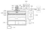
도 2는 본 발명의 제 1 실시예에 따른 유기 박막 증착 장치의 단면 개면도이다. 도 3은 제 1 실시예에 따른 증착원 공급 모듈의 개념도이고, 도 4는 제 1 실시예의 변형예에 따른 증착원 공급 모듈의 개념도이다.2 is a cross-sectional view of the organic thin film deposition apparatus according to the first embodiment of the present invention. 3 is a conceptual diagram of a deposition source supply module according to a first embodiment, and FIG. 4 is a conceptual diagram of a deposition source supply module according to a modification of the first embodiment.
도 2 내지 도 4를 참조하면, 본 실시예에 따른 유기 박막 증착 장치는 불순물이 함유된 증착 물질을 제공하는 증착원 공급 모듈(210, 220, 230, 240)과, 불순물이 함유된 증착 물질을 기화시켜 분사하는 분사부(120)를 구비하는 챔버(100)와, 상기 증착원 공급 모듈(210, 220, 230, 240)의 상기 불순물이 함유된 증착 물질을 분사부(120)에 공급하고 분사부(120)를 회전시키는 구동 모듈(130, 140, 150, 160)을 포함한다.2 to 4, the organic thin film deposition apparatus according to the present embodiment includes a deposition
상기의 챔버(100)는 내측 하부에 마련된 기판 안치 수단(110)과, 그 상측에 마련된 분사부(120)를 포함한다. 그리고, 기판(113)의 출입을 위한 출입부(미도시)와, 챔버(100) 내부의 배기하기 위한 별도의 배기 수단(101)을 더 포함한다.The
여기서, 기판 안치 수단(110)은 기판(113)이 안착되는 안치부(111)와, 안치부(111)를 챔버(100) 바닥에 고정하는 고정부(112)를 포함한다. 그리고, 기판(113)의 로딩 및 언로딩을 돕기 위한 복수의 리프트 핀(미도시)을 더 포함할 수도 있다. 본 실시예에 따른 기판(113)은 사각 판 형상의 투광성 기판을 사용하는 것이 바람직하다. 이에 상기 안치부(111)도 상기 기판(113)에 대응되는 사각형 형상인 것이 바람직하다.Here, the substrate mounting means 110 includes a mounting portion 111 on which the
상기의 분사부(120)는 소정의 내부 공간(122)을 갖는 몸체(121)와, 상기 몸체(121)에 마련된 복수의 노즐(123)과, 상기 내부 공간(122) 내부를 가열하는 가열 수단(124)을 포함한다. 분사부(120)는 파우더 형태의 불순물이 함유된 증착 물질을 공급받고, 이를 가열 수단(124)을 통해 가열하여 기화시켜 기판 안치 수단(110)의 기판(113)에 분사한다.The
이와 같이 본 실시예의 분사부(120)는 가열 수단(124)을 포함하여 파우더 형태의 불순물이 함유된 증착 물질을 기판(113)에 분사되기 직전에 기화시켜 기판(113)에 분사할 수 있다. 상기 가열 수단(124)으로는 상기 몸체(121) 내부에 마련된 발열 부재와 상기 발열 부재에 에너지를 공급하는 에너지 공급부를 포함한다. 이때, 상기 발열 부재로 코일을 사용할 수 있고, 에너지 공급부로 전기 에너지를 공급하는 전원을 사용할 수 있다. 물론 이에 한정되지 않고, 박막 제작을 위한 다양한 가열 수단(124)이 사용될 수도 있다. 이때, 상기 발열 부재를 상기 분사부(120)의 몸체 전 영역에 고르게 배치할 수도 있고, 상기 노즐(123) 영역에 집중하여 배치시킬 수도 있다. 이를 통해 앞서 언급한 바와 같이 파우더 형태의 불순물이 함유된 증착 물질이 기판(113)에 분사되기 직전에 기화될 수 있다.As described above, the
그리고, 몸체(121)는 구동 모듈(130, 140, 150,160)의 회전축(130)에 접속되어 회전 운동을 수행한다. 이를 통해 분사부(120) 내에서 기화되어 분사되는 증착 물질은 기판(113) 전체에 균일하게 공급된다. 이를 통해 기판(113) 전체에 균일한 두께의 불순물이 함유된 유기 박막을 증착할 수 있다. 그리고, 외부에서 불순물이 함유된 증착 물질을 사용하기 때문에 유기 박막 내부의 도핑 농도를 균일하게 유지할 수 있다.In addition, the
상기 분사부(120)에 접속되어 이를 회전시키는 구동모듈은 분사부(120)에 접 속된 회전축(130)과, 상기 회전축(130)을 지지고정하는 하우징(140)과, 상기 회전축(130)을 회전시키는 회전 부재(150)를 포함한다.The driving module connected to the
상기 하우징(140)의 일측에는 불순물이 함유된 증착 물질이 주입되는 주입구(141)가 마련된다. 상기 하우징(140)은 도 2에 도시된 바와 같이 챔버(100)의 상측 영역에 고정된다. 그리고, 상기 하우징(140)의 중심 영역에 회전축(130)이 마련된다.One side of the
회전축(130)의 일단부는 상기 회전 부재(150)에 접속되고, 다른 일단부는 분사부(120)에 접속된다. 상기 회전 부재(150)로는 모터를 사용하는 것이 바람직하다. 회전축(130) 내부에는 파우더 형태의 불순물이 함유된 증착 물질을 이송하는 이송 통로(131)가 마련되고, 이 이송 통로(131)는 상기 분사부(120)의 내부 공간(122)과 연통된다. 그리고, 상기 이송 통로(131)의 끝단은 상기 하우징(140)의 주입구와 대응되는 영역에 마련된다.One end of the
이와 같이 본 실시예에서는 파우더 형태의 불순물이 함유된 증착 물질은 하우징(140)의 주입구(141)를 통해 하우징(140)과 회전축(130)의 이격공간을 거친 다음 회전축(130)의 내부 이송 통로(131)를 통해 분사부(120)로 공급된다. 이때, 상기 하우징(140)과 회전축(130)의 이격 공간을 통해 파우더 형태의 불순물이 함유된 증착 물질이 챔버(100) 내측으로 떨어지는 문제가 발생할 수 있다. 따라서 본 실시예에서는 이를 방지하기 위해 상기 하우징(140)과 회전축(130) 사이의 이격 공간에 베어링 또는 자성유체와 같은 실링 부재(160)를 배치한다. 이때 실링 부재(160)는 도 2에 도시한 바와 같이 상기 하우징(140)의 주입구 상측 및 하측 영역에 배치되 는 것이 바람직하다. 이러한 실링 부재(160)는 상기 하우징(140) 내부의 회전축(130)을 고정 지지하는 역할도 할 수 있다.As described above, in the present embodiment, the deposition material containing the impurity in the form of powder passes through the space between the
이를 통해 상기 하우징(140)의 주입구(141)를 통해 주입된 파우더 형태의 불순물이 함유된 증착 물질은 하우징(140)과 회전축(130)의 이격 공간과 실링 부재(160) 사이 영역에 충진된다. 이 파우더 형태의 불순물이 함유된 증착 물질은 회전축(130)의 이송 공간을 통해 챔버(100) 내측의 분사부(120)의 내부 공간(122)에 공급된다.As a result, the deposition material containing the impurity in the form of powder injected through the
상기 하우징(140)의 주입구(141)에 불순물이 함유된 증착 물질을 공급하는 증착원 공급 모듈(210, 220, 230, 240)에 관해 설명하면 다음과 같다.The deposition
상기의 증착원 공급 모듈(210, 220, 230, 240)은 캐리어 가스(CG)를 공급하는 캐리어 가스 공급부(210)와, 유기 원료 물질을 공급하는 유기 원료 물질 공급부(220)와, 불순물 원료 물질을 공급하는 분순물 원료 물질 공급부(230)와, 유기 원료 물질과 불순물 원료 물질을 혼합하여 불순물이 함유된 증착 물질을 제작하고, 상기 불순물이 함유된 증착 물질을 캐리어 가스(CG)를 이용하여 구동 모듈(130, 140, 150, 160)에 제공하는 이송부(240)를 포함한다.The deposition
여기서, 캐리어 가스 공급부(210)는 도시되지는 않았지만 캐리어 가스(CG)를 저장하는 저장 탱크와 이를 고압으로 분사하는 분사부를 포함할 수 있다. 그리고, 캐리어 가스(CG)의 분사량을 제어하는 제어부(211)를 더 포함할 수 있다. 이러한 제어부(211)로는 도 3에 도시된 바와 같이 밸브를 사용하는 것이 바람직하다. 캐리어 가스(CG)로는 비활성의 기체를 사용하는 것이 바람직하다. 상기 이송부(240)는 캐리어 가스(CG)를 이용하여 상기 불순물이 함유된 증착 물질을 구동 모듈(130, 140, 150, 160)에 제공한다.Although not shown, the carrier
이송부(240)는 상기 캐리어 가스(CG)가 지나가는 파이프(242)를 포함한다. 그리고, 상기 파이프(242)에는 상기 유기 원료 물질 공급부(220)와 불순물 원료 물질 공급부(230)가 접속된다. 이를 통해 상기 파이프(242) 내부에서 유기 원료 물질과 불순물 원료 물질이 혼합되어 불순물이 함유된 증착 물질을 제작한다. 물론 이에 한정되지 않고, 상기 이송부(240) 내에는 소정의 혼합 영역(미도시)이 마련되고, 이 혼합 영역에 유기 원료 물질 공급부(220)와 불순물 원료 물질 공급부(230)가 접속될 수도 있다. 이로 인해 상기 별도의 혼합 영역에서 유기 원료 물질과 불순물 원료 물질이 혼합되어 불순물이 함유된 증착 물질을 제작할 수도 있다. 상기 이송부(240)는 도 3에 도시된 바와 같이 상기 파이프(242)를 통해 공급되는 불순물이 함유된 증착 물질의 공급을 제어하는 제어 밸브(241)를 더 포함할 수 있다.The
유기 원료 물질 공급부(220)는 파우더 형태의 유기 원료 물질이 저장되고 이를 이송부(240)에 공급하는 유기 원료 저장부(221)와, 상기 유기 원료 물질의 공급량을 제어하는 유기 원료 제어부(222)를 포함한다.The organic raw
상기 불순물 원료 물질 공급부(230)는 파우더 형태의 불순물 원료 물질이 저장되고 이를 이송부(240)에 공급하는 불순물 저장부(231)와, 상기 불순물 원료 물질의 공급량을 제어하는 불순물 원료 제어부(232)를 포함한다.The impurity raw
상기 불순물 저장부(231)와 이송부(240) 사이에 상기 불순물 원료 물질이 저장되는 별도의 저장 공간이 더 마련될 수 있다. 이를 통해 미량의 불순물 원료 물 질이 불순물 저장부(231)에서 저장 공간에 미리 저장된 다음 캐리어 가스(CG)에 의해 이송부(240)으로 전달될 수도 있다. 이때, 상기 저장 공간에 저장되는 미량이 불순물 원료 물질은 기판(113) 상에 형성되는 유기 박막 내에 도핑될 불순물의 양에 대응되는 양만큼이 저장되는 것이 바람직하다. 이를 통해 복수의 기판상에 불순물 도핑된 유기 박막을 형성할 경우 상기 저장 공간에 저장되는 불순물 원료 물질의 양을 균일하게 하여, 각 기판(113)상에 형성되는 불순물 도핑된 유기 박막의 불순물 도핑량을 균일하게 유지할 수도 있다.A separate storage space for storing the impurity raw material may be further provided between the
상기의 유기 원료 제어부(222)와 불순물 원료 제어부(232)로 밸브를 사용할 수 있다. 물론 이에 한정되지 않고 파우더 형태의 원료 물질의 공급량을 제어할 수 있는 다양한 제어 수단이 사용될 수 있다.이러한 제어 수단으로는 파우더 형태의 유기 원료 물질 또는 불순물 원료 물질은 일정량으로 토출하는 펌프와 디스펜서등을 사용할 수 있다. 이러한 유기 원료 제어부(222)와 불순물 원료 제어부(232)를 통해 이송부(240)로 토출되는 유기 원료 물질과 불순물 원료 물질의 공급량을 각기 다양하게 제어할 수 있다. 이를 통해 불순물이 함유된 증착 물질 내부의 불순물 량을 목표로 하는 양으로 쉽게 제어할 수 있다.Valves may be used as the organic raw
본 실시예에서는 불순물이 함유된 증착 물질 내의 상기 유기 원료 물질과 불순물 원료 물질의 혼합량을 제어하여 기판(113)상에 형성되는 유기 박막의 불순물 도핑 비율을 제어한다. 이때, 상기 이송부(240)에 제공되는 유기 원료 물질과 불순물 원료 물질의 공급량을 제어하는 것이 바람직하다. 이때, 유기 원료 물질과 불순물 원료 물질의 공급량은 기판(113) 상에 형성될 유기 박막의 불순물 도핑량에 따 라 다양하게 변화될 수 있다. 여기서, 유기 원료 물질과 불순물 원료 물질의 몰비(mole raion)를 0.3 내지 1%로 제어하는 것이 바람직하다.In the present exemplary embodiment, an impurity doping ratio of the organic thin film formed on the
본 실시예에서는 캐리어 가스(CG)가 이동하는 파이프(242) 내부에 파우더 형태의 유기 원료 물질을 공급하고, 파우더 형태의 미량의 불순물 원료 물질을 공급한다. 여기서, 유기 원료 물질과 미량의 불순물 원료 물질은 캐리어 가스(CG)에 의해 파이프(242)를 따라 이동하며 이때, 상기 파우더 형태의 유기 원료 물질과 불순물 원료는 파이프(242) 내부에서 혼합되어 불순물이 함유된 증착 물질이 된다. 상기 파이프(242) 내의 불순물이 함유된 증착 물질은 캐리어 가스(CG)를 따라 하우징(140)의 주입구(141)에 제공되어 회전축(130)의 이동 통로(131)를 통해 분사부(120)의 내부 공간(122)으로 공급된다.In this embodiment, the organic raw material in powder form is supplied into the
본 실시예에서는 유기 원료 제어부와 불순물 원료 제어부를 통해 유기 원료 저장부(221)와 불순물 저장부(231)의 유기 원료 물질과 불순물 원료 물질 각각이 이송부(240)로 토출되는 양을 제어함에 관해 설명하였다. 그러나 본 발명은 이에 한정되지 않고, 다양한 방법과 구조를 통해 상기 이송부(240)로 제공되는 유기 원료 물질과 불순물 원료 물질의 공급량을 제어할 수 있다.In the present embodiment, the organic raw material control unit and the impurity raw material control unit through the organic raw
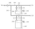
이에 따른 일 변형예로 도 4에 도시된 바와 같이 유기 원료 물질은 제 1 파이프(243)에 의해 이송되고, 불순물 원료 물질은 제 2 파이프(244)에 의해 이송된다. 그리고, 제 1 및 제 2 파이프(243, 244)가 연통된 제 3 파이프(245)에 의해 상기 유기 원료 물질과 불순물 원료 물질이 혼합되어 불순물이 함유된 증착 물질을 형성하고 이를 챔버(100)의 분사부(120)에 공급한다.As a variation of this, as shown in FIG. 4, the organic raw material is transported by the
이를 도 4를 참조하여 좀더 구체적으로 설명하면 다음과 같다.This will be described in more detail with reference to FIG. 4 as follows.
유기 원료 저장부(221)의 유입구와 배출구는 제 1 파이프(243)와 연통된다. 그리고, 상기 유기 원료 저장부(221)의 일측에는 제 1 압력 조절부(223)가 마련된다. 상기 유입구 및 배출구 상측에는 제 1 및 제 2 밸브(V1, V2)가 마련된다. 상기 유입구와 배출구 사이의 제 1 파이프(243) 내에는 제 3 밸브(V3)가 마련된다. 유기 원료 저장부(221) 내부에는 고체 분말 형태의 유기 원료 물질의 역류를 방지하는 제 1 블럭부(224)가 마련된다. 이때, 상기의 제 2 밸브(V2)는 유기 원료 저장부(221)로 유입되는 캐리어 가스(CG1)의 유입량을 제어한다. 그리고, 제 1 밸브(V1)는 유기 원료 저장부(221) 내부의 파우더 형태의 유기 증착 원료의 배출을 제어한다.Inlets and outlets of the organic raw
불순물 저장부(231) 영역도 상술한 유기 원료 저장부(221)와 동일한 구성을 갖는다. 즉, 불순물 저장부(231)의 유입구와 배출구가 제 2 파이프(244)와 연통되고, 유입구 및 배출구 상측에 제 1 및 제 2 밸브(V4, V5)가 마련되고, 불순물 저장부(231)의 일측에는 제 2 압력 조절부(233)가 마련되고, 불순물 저장부(231) 내부에는 블럭부(234)가 배치된다.The
상술한 구성을 갖는 본 발명의 일 변형예에 따른 증착원 공급 모듈의 동작을 유기 원료 물질을 기준으로 설명하면 다음과 같다.Referring to the operation of the deposition source supply module according to a modification of the present invention having the above configuration based on the organic raw material as follows.
우선 파우더 형태의 유기 원료 물질은 유기 원료 저장부(221) 내부의 상태에 따라(즉, 층류(Laminar flow) 방식과 난류(Turbulence flow) 방식) 제 1 파이프(243)에 제공된다. 먼저 층류 방식을 설명하면, 제 1 압력 조절부(223)의 압력을 일정하게 유지한 상태에서 제 1 및 제 2 밸브(V1, V2)를 개방하고 제 3 밸브(V3)를 폐쇄하면, 유기 원료 저장부(221)의 파우더 형태의 유기 원료 물질은 캐리어 가스(CG1)에 의해 제 1 파이프(243)로 공급된다. 이때, 상기 제 1 압력 조절부(223)의 압력을 조절하거나, 유입되는 캐리어 가스(CG1)의 유입량을 조절하여 제 1 파이프(243)에 공급되는 유기 원료 물질의 공급량을 조절할 수 있다. 또한, 제 3 밸브(V3)를 개방하게 되면 제 2 밸브(V2)로 유입되는 캐리어 가스의 양을 제어할 수 있어 유기 원료 물질의 공급량을 제어할 수 있게 된다. 난류 방식을 설명하면 상기의 제 2 밸브(V2)를 개방하고, 제 1 밸브(V1)를 소정 시간 간격으로 개폐시키고, 제 3 밸브(V3)를 폐쇄시키면 제 1 파이프(243)의 내부 압력과 유기 원료 저장부(221)의 내부 압력 간의 변화로 인해 유기 원료 저장부(221) 내부에서 와류가 발생한다. 이러한 와류 현상으로 인해 파우더 형태의 유기 원료 물질이 제 1 파이프(243)로 공급된다. 이때, 제 1 밸브(V1)의 개방 시간을 조절하여 유기 원료 물질의 공급량을 제어할 수 있다. 그리고, 제 1 파이프(243)와 유기 원료 저장부(221) 내측의 압력차를 조절하여 유기 원료 물질의 공급량을 제어할 수 있다.First, the organic raw material in powder form is provided to the
상술한 제어 방법으로 제 1 및 제 2 파이프(243, 244)로 각기 제공된 유기 원료 물질과 불순물 원료 물질의 양을 다양하게 제어할 수 있게 된다.The control method described above makes it possible to control various amounts of the organic raw material and the impurity raw material respectively provided to the first and
하기에서는 예에 따른 유기 박막 증착 장치를 이용한 불순물 도핑된 유기 박막의 증착을 설명한다.Hereinafter, deposition of an impurity doped organic thin film using an organic thin film deposition apparatus according to an example will be described.
챔버(100) 내부로 기판(113)을 로딩시켜 기판 안치 수단(110) 상에 기판(113)을 안착시킨다. 분사부(120)가 소정 온도가 되도록 가열하고, 회전 부 재(150)의 회전력을 회전축(130)을 통해 분사부(120)에 인가한다. 이를 통해 분사부(120)가 챔버(100) 내에서 회전되도록 한다. 이후, 캐리어 가스 공급부(210)를 통해 캐리어 가스(CG)를 이송부(240)의 파이프(242) 내부로 공급한다. 이때, 유기 원료 물질과 불순물 원료 물질도 함께 이송부(240)에 공급한다. 유기 원료 물질 공급부(220)와 불순물 원료 물질 공급부(230)의 공급량을 제어하여 이송부(240) 내부로 공급되는 유기 원료 물질과 불순물 원료 물질의 양을 제어한다. 그리고 상기 이송부(240) 내에서 유기 원료 물질과 불순물 원료 물질은 혼합되어 불순물이 함유된 증착 물질을 형성한다. 이 증착 물질은 이송부(240)를 통해 하우징(140)의 주입구(141)로 공급되어 챔버(100) 내에서 회전하는 분사부(120)에 제공된다. 분사부(120)로 제공된 불순물이 함유된 증착 물질은 분사부(120) 내에서 기화되어 분사부(120)의 노즐(123)을 통해 기판(113)으로 분사되어 기판(113) 상에 불순물이 함유된 유기 박막을 형성한다.The
이와 같이 본 실시예에서는 일정한 비율로 유기 원료 물질과 불순물 원료 물질을 공급하고, 기판(113)에 분사되기 직전에 이러한 물질들을 기화시켜 우수한 막질의 유기 박막을 형성할 수 있고, 유기 박막 내의 불순물 도핑량을 균일하게 할 수 있다. 상술한 공정을 복수번 반복하더라도 챔버(110) 내에 공급되는 유기 원료 물질과 불순물 원료 물질의 양을 균일하게 하여, 복수 공정을 통해 그 상부에 유기 박막이 형성된 각 기판(113) 별로 균일한 불순물 량을 갖는 유기 박막을 형성할 수 있다. 또한, 분사부(120)가 회전하여 기판(113) 상에 균일한 증착 물질을 공급할 수 있어 기판(113) 전체적으로 균일한 두께의 유기 박막을 형성할 수 있다.As described above, in the present exemplary embodiment, the organic raw material and the impurity raw material are supplied at a constant ratio, and the organic materials are vaporized immediately before being sprayed onto the
또한, 본 발명은 상술한 바와 같이 캐리어 가스와 이송부 내에서 파우더 형태의 유기 원료 물질과 분순물 원료 물질을 혼합하지 않고, 별도로 파우더 형태의 유기 원료 물질과 분순물 원료 물질은 혼합한 다음 이를 캐리어 가스를 이용하여 챔버 내부의 분사부에 공급할 수도 있다. 하기에서는 도면을 참조하여 본 발명의 제 2 실시예에 따른 유기 박막 증착 장치를 설명한다. 후술되는 설명중 상술한 설명과 중복되는 설명은 생략한다. 후술되는 설명의 기술은 앞서 설명한 실시예에 적용될 수 있다.In addition, the present invention does not mix the powdered organic raw material and the powdered raw material in the carrier gas and the transfer unit as described above, separately the powdered organic raw material and the powdered raw material and then the carrier gas It may be supplied to the injection unit inside the chamber using. Hereinafter, an organic thin film deposition apparatus according to a second embodiment of the present invention will be described with reference to the drawings. The description overlapping with the above description will be omitted. The description of the following description can be applied to the above-described embodiment.
도 5는 본 발명의 제 2 실시예에 따른 유기 박막 증착 장치의 단면 개면도이다. 도 3은 제 1 실시예에 따른 증착원 공급 모듈의 개념도이다.5 is a cross-sectional open view of an organic thin film deposition apparatus according to a second exemplary embodiment of the present invention. 3 is a conceptual diagram of a deposition source supply module according to a first embodiment.
도 5 및 도 6을 참조하면, 본 실시예에 따른 유기 박막 증착 장치는 소정의 반응 공간을 갖는 챔버(100)와, 상기 반응 공간 내부에 마련된 기판 안치 수단(110)과 분사부(120) 그리고, 상기 분사부(120)를 회전시키기 위한 하우징(140)과 회전축(130) 및 회전 부재(160)를 포함한다. 그리고, 상기 분사부(120)에 파우더 형태의 유기 원료 물질에 파우더 형태의 불순물 원료 물질이 혼합된 불순물이 함유된 증착 물질을 제공하는 불순물 함유 증착 물질 공급부(200)와, 파우더 형태의 불순물이 함유된 증착 물질을 분사부(120)로 이송하는 캐리어 가스(CG)를 제공하는 캐리어 가스 공급부(210)를 포함한다. 그리고, 상기 파우더 형태의 불순물과 캐리어 가스(CG)가 지나가는 이송부(240)을 포함한다.5 and 6, the organic thin film deposition apparatus according to the present embodiment includes a
상기 불순물 함유 증착 물질 공급부(200)는 파우더 형태의 유기 원료 물질 및 불순물 원료 물질이 미리 혼합되어 불순물이 함유된 증착 물질 형태로 저장되어 있는 증착 물질 저장부(201)와, 상기 증착 물질 저장부로부터 불순물이 함유된 증착 물질을 제공받아 캐리어 가스(CG)와 이송부(240)를 통해 챔버(100) 내부의 분사부(120)로 공급하는 증착 물질 공급 수단(202)을 포함한다.The impurity-containing deposition
상기 증착 물질 저장부(201)는 증착 물질의 공급량 제어를 위한 소정의 제어 수단이 마련될 수 있다. 상기 증착 물질 공급 수단(202)은 증착 물질 저장부(201), 이송부(240) 및 캐리어 가스 공급부(210) 사이에 마련되는 것이 바람직하다.The deposition
이와 같이 본 실시예에서는 파우더 형태의 유기 원료 물질과 불순물 원료 물질을 먼저 혼합하여 불순물이 함유된 증착 물질을 제작한 다음 이를 증착 물질 저장부(201)에 저장하고, 매 공정마다 필요한 양만큼 증착 물질 공급 수단(202)에 제공한다. 이와 같이 파우더 형태의 유기 원료 물질과 불순물 원료 물질을 혼합하기 때문에 이둘간의 혼합이 잘 이루어질 뿐만 아니라 유기 원료 물질과 불순물 원료 물질 간의 조성비를 정확하게 제어할 수 있게 된다. 이를 통해 불순물 도핑된 유기 박막의 도핑 비율을 정량적으로 조절할 수 있다. 그리고, 이뿐만 아니라 고분자 박막 제작을 위한 적어도 두개 이상의 전구체(pre-cursor)를 혼합할 수도 있다. 이를 통해 폴리이미드(palyimide) 또는 폴리아미드(polyamide)등의 고분자 박막을 형성할 수 있다.As described above, in the present embodiment, an organic raw material and an impurity raw material in powder form are first mixed to prepare a deposition material containing impurities, and then stored in the deposition
본 발명은 상술한 설명에 한정되지 않고, 상기 분사부가 고정되고 기판이 회전하여 균일한 두께의 불순물이 도핑된 유기 박막을 형성할 수도 있다. 하기에서는 도면을 참조하여 본 발명의 제 3 실시예에 따른 유기 박막 증착 장치를 설명한다. 후술되는 설명중 상술한 설명들과 중복되는 설명은 생략한다. 후술되는 설명의 기 술은 앞서 설명한 실시예들에 적용될 수 있다.The present invention is not limited to the above description, and the spraying part is fixed and the substrate may be rotated to form an organic thin film doped with impurities having a uniform thickness. Hereinafter, an organic thin film deposition apparatus according to a third embodiment of the present invention will be described with reference to the drawings. Descriptions overlapping with the descriptions above will be omitted. The description of the following description can be applied to the above-described embodiments.
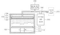
도 7은 본 발명의 제 3 실시예에 따른 유기 박막 증착 장치의 단면 개념도이다.7 is a cross-sectional conceptual view of an organic thin film deposition apparatus according to a third embodiment of the present invention.
도 7을 참조하면, 본 실시예에 따른 유기 박막 증착 장치는 챔버(100)와, 챔버(100) 내부에 마련되고 회전하는 기판 안치 수단(111)과, 불순물이 함유된 증착 물질을 기화시켜 챔버(100) 내부에 공급하는 분사부(120)와, 상기 분사부(120)에 증착 물질을 공급하는 증착원 공급 모듈(210, 220, 230, 240)을 포함한다.Referring to FIG. 7, the organic thin film deposition apparatus according to the present exemplary embodiment includes vaporizing a
기판 안치 수단은 기판이 안착되는 안치부(111)과, 안치부(111)를 회전시키는 구동부(114)를 포함한다. 구동부(114)는 안치부(111)에 접속되어 이를 회전시키는 구동축과 상기 구동축을 회전시키는 구동수단을 포함한다. 상술한 구동부(112)를 통해 기판(113)이 안치되는 안치부(111)를 회전시켜 분사부(120)를 통해 공급되는 증착 물질이 기판(113) 상측에 고르게 분포되도록 할 수 있어 기판(113) 상에 형성되는 박막의 두께를 균일하게 할 수 있다. 분사부(120)는 내부 공간(122)을 갖는 몸체(121)와, 노즐(123) 및 가열 수단(124)을 포함한다.The substrate mounting means includes a mounting portion 111 on which the substrate is mounted, and a driving portion 114 for rotating the mounting portion 111. The driving unit 114 includes a driving shaft connected to the settlement unit 111 to rotate the driving shaft and a driving means for rotating the driving shaft. The deposition unit supplied through the
증착원 공급 모듈(210, 220, 230, 240)은 상기 분사부(120)의 내부 공간(121)에 유기 원료 물질을 공급하는 유기 원료 물질 공급부(220)와 불순물 원료 물질을 공급하는 불순물 원료 물질 공급부(230)를 포함한다. 이때, 상기 파우더 형태의 유기 원료 물질과 분순물 원료 물질은 소정의 이송부(240)에 공급되고, 이송부(240) 내에서 캐리어 가스(CG)에 의해 이송되어 분사부(120)에 공급된다. 그리고, 캐리어 가스를 공급하는 캐리어 가스 공급부(210)를 더 포함한다. 본 실시예에 서는 증착원 공급 모듈(210, 220, 230, 240)의 원료 물질을 바로 분사부(120)에 제공할 수 있다. 본 실시예에서는 유기 원료 물질과 불순물 원료 물질의 공급량 조절을 통하여 목표로 하는 도핑 농도의 불순물을 갖는 유기 박막을 제작할 수 있다.Deposition source supply module (210, 220, 230, 240) is an organic raw
상술한 바와 같이 본 발명은 파우더 형태의 유기 원료 물질과 불순물 원료 물질을 챔버 내부로 공급하는 공급 량을 조절하여 목표로 하는 불순물 농도를 갖는 유기 박막을 제작할 수 있다.As described above, the present invention may produce an organic thin film having a target impurity concentration by adjusting a supply amount for supplying an organic raw material and an impurity raw material in a powder form into the chamber.
또한, 본 발명은 유기 원료 물질과 불순물 원료 물질의 공급량 제어를 통해 불순물이 도핑된 유기 박막의 도핑 비율을 미세하고 정량적으로 제어할 수 있다.In addition, the present invention can finely and quantitatively control the doping ratio of the organic thin film doped with impurities through the supply amount control of the organic raw material and the impurity raw material.
또한, 본 발명은 챔버 외부에서 공급된 유기 원료 물질과 불순물 원료 물질을 분사부 내부에서 동시에 기화시켜 불순물 도핑을 최적화할 수 있다.In addition, the present invention can optimize the impurity doping by vaporizing the organic raw material and the impurity raw material supplied from the outside of the chamber at the same time in the injection unit.
또한, 본 발명은 다수의 공정 진행시 챔버 내부로 공급되는 유기 원료 물질과 불순물 원료 물질의 공급량을 일정하게 유지하여 불순물이 함유된 유기 박막의 재현성을 향상시킬 수 있다.In addition, the present invention maintains a constant supply amount of the organic raw material and the impurity raw material supplied into the chamber during a plurality of processes to improve the reproducibility of the organic thin film containing impurities.
본 발명은 상기에서 서술된 실시예에 한정되는 것이 아니라 서로 다른 다양한 형태로 구현될 수 있다. 즉, 상기의 실시예는 본 발명의 개시가 완전하도록 하며 통상의 지식을 가진 자에게 발명의 범주를 완전하게 알려주기 위해 제공되는 것이며, 본 발명의 범위는 본원의 특허 청구 범위에 의해서 이해되어야 한다.The present invention is not limited to the above-described embodiments, but may be implemented in various forms. That is, the above embodiments are provided to make the disclosure of the present invention complete and to fully inform those skilled in the art of the scope of the present invention, and the scope of the present invention should be understood by the claims of the present application. .
Claims (16)
Translated fromKoreanPriority Applications (3)
| Application Number | Priority Date | Filing Date | Title |
|---|---|---|---|
| KR1020060082187AKR20080019808A (en) | 2006-08-29 | 2006-08-29 | Organic thin film deposition apparatus and method |
| PCT/KR2007/004133WO2008026865A1 (en) | 2006-08-29 | 2007-08-28 | Apparatus and method for depositing organic thin film |
| TW096131939ATWI424600B (en) | 2006-08-29 | 2007-08-28 | Apparatus and method for depositing organic thin film |
Applications Claiming Priority (1)
| Application Number | Priority Date | Filing Date | Title |
|---|---|---|---|
| KR1020060082187AKR20080019808A (en) | 2006-08-29 | 2006-08-29 | Organic thin film deposition apparatus and method |
Publications (1)
| Publication Number | Publication Date |
|---|---|
| KR20080019808Atrue KR20080019808A (en) | 2008-03-05 |
Family
ID=39136105
Family Applications (1)
| Application Number | Title | Priority Date | Filing Date |
|---|---|---|---|
| KR1020060082187ACeasedKR20080019808A (en) | 2006-08-29 | 2006-08-29 | Organic thin film deposition apparatus and method |
Country Status (3)
| Country | Link |
|---|---|
| KR (1) | KR20080019808A (en) |
| TW (1) | TWI424600B (en) |
| WO (1) | WO2008026865A1 (en) |
Cited By (4)
| Publication number | Priority date | Publication date | Assignee | Title |
|---|---|---|---|---|
| WO2009114112A3 (en)* | 2008-03-08 | 2009-12-10 | Omniprobe, Inc. | Method and apparatus for precursor delivery system for irradiation beam instruments |
| KR101370326B1 (en)* | 2012-08-07 | 2014-03-05 | 한국표준과학연구원 | Evaporation Deposition Apparatus |
| KR20220067866A (en) | 2020-11-18 | 2022-05-25 | 주성엔지니어링(주) | Raw material feeder and apparatus for processing substrate having the same |
| KR20220134497A (en)* | 2014-06-25 | 2022-10-05 | 유니버셜 디스플레이 코포레이션 | Systems and methods of modulating flow during vapor jet deposition of organic materials |
Family Cites Families (9)
| Publication number | Priority date | Publication date | Assignee | Title |
|---|---|---|---|---|
| US6271498B1 (en)* | 1997-06-23 | 2001-08-07 | Nissin Electric Co., Ltd | Apparatus for vaporizing liquid raw material and method of cleaning CVD apparatus |
| JP2002016058A (en)* | 2000-04-25 | 2002-01-18 | Hitachi Cable Ltd | Method and apparatus for manufacturing dielectric film and dielectric film |
| JP3628997B2 (en)* | 2000-11-27 | 2005-03-16 | セイコーエプソン株式会社 | Method for manufacturing organic electroluminescence device |
| US7067241B2 (en)* | 2002-05-08 | 2006-06-27 | Unaxis Balzers Aktiengesellschaft | Method for producing a unit having a three-dimensional surface patterning, and use of this method |
| JP4019258B2 (en)* | 2002-06-25 | 2007-12-12 | 日本電気株式会社 | Method for producing copolymerized polymer film |
| JP4139952B2 (en)* | 2002-07-31 | 2008-08-27 | 日本電気株式会社 | COPOLYMER POLYMER FILM, METHOD FOR FORMING THE SAME, AND SEMICONDUCTOR DEVICE USING COPOLYMER POLYMER FILM |
| JP4013859B2 (en)* | 2003-07-17 | 2007-11-28 | 富士電機ホールディングス株式会社 | Organic thin film manufacturing equipment |
| US7404986B2 (en)* | 2004-05-07 | 2008-07-29 | United Technologies Corporation | Multi-component deposition |
| JP4506953B2 (en)* | 2004-05-28 | 2010-07-21 | 日本電気株式会社 | Copolymer film and method for producing the same |
- 2006
- 2006-08-29KRKR1020060082187Apatent/KR20080019808A/ennot_activeCeased
- 2007
- 2007-08-28TWTW096131939Apatent/TWI424600B/enactive
- 2007-08-28WOPCT/KR2007/004133patent/WO2008026865A1/enactiveApplication Filing
Cited By (6)
| Publication number | Priority date | Publication date | Assignee | Title |
|---|---|---|---|---|
| WO2009114112A3 (en)* | 2008-03-08 | 2009-12-10 | Omniprobe, Inc. | Method and apparatus for precursor delivery system for irradiation beam instruments |
| US8512474B2 (en) | 2008-03-08 | 2013-08-20 | Omniprobe, Inc. | Apparatus for precursor delivery system for irradiation beam instruments |
| KR101370326B1 (en)* | 2012-08-07 | 2014-03-05 | 한국표준과학연구원 | Evaporation Deposition Apparatus |
| KR20220134497A (en)* | 2014-06-25 | 2022-10-05 | 유니버셜 디스플레이 코포레이션 | Systems and methods of modulating flow during vapor jet deposition of organic materials |
| KR20230129355A (en)* | 2014-06-25 | 2023-09-08 | 유니버셜 디스플레이 코포레이션 | Systems and methods of modulating flow during vapor jet deposition of organic materials |
| KR20220067866A (en) | 2020-11-18 | 2022-05-25 | 주성엔지니어링(주) | Raw material feeder and apparatus for processing substrate having the same |
Also Published As
| Publication number | Publication date |
|---|---|
| TWI424600B (en) | 2014-01-21 |
| TW200818564A (en) | 2008-04-16 |
| WO2008026865A1 (en) | 2008-03-06 |
Similar Documents
| Publication | Publication Date | Title |
|---|---|---|
| US7201942B2 (en) | Coating method | |
| JP5298189B2 (en) | Vacuum deposition method and apparatus | |
| US20090017638A1 (en) | Substrate processing apparatus and method for manufacturing semiconductor device | |
| US20160273101A1 (en) | Raw material gas supply apparatus and film forming apparatus | |
| US20050116064A1 (en) | Reactors having gas distributors and methods for depositing materials onto micro-device workpieces | |
| US20040182316A1 (en) | Processing equipment and processing method | |
| CN102758191A (en) | Apparatus and method for treating substrate | |
| KR100473806B1 (en) | Method and apparatus using large area organic vapor deposition for organic thin film and organic devices | |
| US20050217575A1 (en) | Ampoules for producing a reaction gas and systems for depositing materials onto microfeature workpieces in reaction chambers | |
| KR20080019808A (en) | Organic thin film deposition apparatus and method | |
| CN110965050A (en) | Semiconductor device and gas supply system thereof | |
| JP2005213570A (en) | Vacuum vapor deposition machine | |
| KR20130070037A (en) | Canister for producing semiconductor | |
| KR20070075767A (en) | Source powder feeder for chemical vapor deposition | |
| US8440018B2 (en) | Apparatus for supplying source and apparatus for deposition thin film having the same | |
| KR101062589B1 (en) | Atomic layer deposition apparatus | |
| KR100722848B1 (en) | Thin film deposition apparatus | |
| CN101481796A (en) | Gas injector and film deposition apparatus having the same | |
| KR101854900B1 (en) | Material supplying apparatus and thin film depositing system having the same | |
| JP2003520903A (en) | Method and apparatus for depositing at least one precursor in liquid or dissolved form on at least one substrate | |
| KR102817870B1 (en) | Equipment for deposition unit with manifoid unit | |
| CN103748262A (en) | Direct liquid injection for halide vapor phase epitaxy systems and methods | |
| KR101195131B1 (en) | Apparatus for supplying deposition meterial and film depositing system having the same | |
| KR101232908B1 (en) | A chemical vapor dipositino apparatus | |
| KR101075569B1 (en) | Apparatus for uniformly supplying of deposition material |
Legal Events
| Date | Code | Title | Description |
|---|---|---|---|
| PA0109 | Patent application | Patent event code:PA01091R01D Comment text:Patent Application Patent event date:20060829 | |
| PG1501 | Laying open of application | ||
| A201 | Request for examination | ||
| PA0201 | Request for examination | Patent event code:PA02012R01D Patent event date:20110818 Comment text:Request for Examination of Application Patent event code:PA02011R01I Patent event date:20060829 Comment text:Patent Application | |
| E902 | Notification of reason for refusal | ||
| PE0902 | Notice of grounds for rejection | Comment text:Notification of reason for refusal Patent event date:20130401 Patent event code:PE09021S01D | |
| E601 | Decision to refuse application | ||
| PE0601 | Decision on rejection of patent | Patent event date:20130903 Comment text:Decision to Refuse Application Patent event code:PE06012S01D Patent event date:20130401 Comment text:Notification of reason for refusal Patent event code:PE06011S01I |