KR20080012210A - Pneumatically-powered surgical cutting device with manual retractor - Google Patents
Pneumatically-powered surgical cutting device with manual retractorDownload PDFInfo
- Publication number
- KR20080012210A KR20080012210AKR1020070076804AKR20070076804AKR20080012210AKR 20080012210 AKR20080012210 AKR 20080012210AKR 1020070076804 AKR1020070076804 AKR 1020070076804AKR 20070076804 AKR20070076804 AKR 20070076804AKR 20080012210 AKR20080012210 AKR 20080012210A
- Authority
- KR
- South Korea
- Prior art keywords
- assembly
- firing
- distal
- proximal
- operating position
- Prior art date
- Legal status (The legal status is an assumption and is not a legal conclusion. Google has not performed a legal analysis and makes no representation as to the accuracy of the status listed.)
- Granted
Links
Images


Classifications
- A—HUMAN NECESSITIES
- A61—MEDICAL OR VETERINARY SCIENCE; HYGIENE
- A61B—DIAGNOSIS; SURGERY; IDENTIFICATION
- A61B17/00—Surgical instruments, devices or methods
- A—HUMAN NECESSITIES
- A61—MEDICAL OR VETERINARY SCIENCE; HYGIENE
- A61B—DIAGNOSIS; SURGERY; IDENTIFICATION
- A61B17/00—Surgical instruments, devices or methods
- A61B17/068—Surgical staplers, e.g. containing multiple staples or clamps
- A—HUMAN NECESSITIES
- A61—MEDICAL OR VETERINARY SCIENCE; HYGIENE
- A61B—DIAGNOSIS; SURGERY; IDENTIFICATION
- A61B17/00—Surgical instruments, devices or methods
- A61B17/068—Surgical staplers, e.g. containing multiple staples or clamps
- A61B17/072—Surgical staplers, e.g. containing multiple staples or clamps for applying a row of staples in a single action, e.g. the staples being applied simultaneously
- A61B17/07207—Surgical staplers, e.g. containing multiple staples or clamps for applying a row of staples in a single action, e.g. the staples being applied simultaneously the staples being applied sequentially
- A—HUMAN NECESSITIES
- A61—MEDICAL OR VETERINARY SCIENCE; HYGIENE
- A61B—DIAGNOSIS; SURGERY; IDENTIFICATION
- A61B17/00—Surgical instruments, devices or methods
- A61B17/10—Surgical instruments, devices or methods for applying or removing wound clamps, e.g. containing only one clamp or staple; Wound clamp magazines
- A—HUMAN NECESSITIES
- A61—MEDICAL OR VETERINARY SCIENCE; HYGIENE
- A61B—DIAGNOSIS; SURGERY; IDENTIFICATION
- A61B17/00—Surgical instruments, devices or methods
- A61B17/12—Surgical instruments, devices or methods for ligaturing or otherwise compressing tubular parts of the body, e.g. blood vessels or umbilical cord
- A61B17/122—Clamps or clips, e.g. for the umbilical cord
- A—HUMAN NECESSITIES
- A61—MEDICAL OR VETERINARY SCIENCE; HYGIENE
- A61B—DIAGNOSIS; SURGERY; IDENTIFICATION
- A61B17/00—Surgical instruments, devices or methods
- A61B17/00234—Surgical instruments, devices or methods for minimally invasive surgery
- A61B2017/00292—Surgical instruments, devices or methods for minimally invasive surgery mounted on or guided by flexible, e.g. catheter-like, means
- A61B2017/003—Steerable
- A—HUMAN NECESSITIES
- A61—MEDICAL OR VETERINARY SCIENCE; HYGIENE
- A61B—DIAGNOSIS; SURGERY; IDENTIFICATION
- A61B17/00—Surgical instruments, devices or methods
- A61B2017/00367—Details of actuation of instruments, e.g. relations between pushing buttons, or the like, and activation of the tool, working tip, or the like
- A61B2017/00398—Details of actuation of instruments, e.g. relations between pushing buttons, or the like, and activation of the tool, working tip, or the like using powered actuators, e.g. stepper motors, solenoids
- A—HUMAN NECESSITIES
- A61—MEDICAL OR VETERINARY SCIENCE; HYGIENE
- A61B—DIAGNOSIS; SURGERY; IDENTIFICATION
- A61B17/00—Surgical instruments, devices or methods
- A61B2017/00535—Surgical instruments, devices or methods pneumatically or hydraulically operated
- A61B2017/00544—Surgical instruments, devices or methods pneumatically or hydraulically operated pneumatically
- A61B2017/00548—Gas cartridges therefor
- A—HUMAN NECESSITIES
- A61—MEDICAL OR VETERINARY SCIENCE; HYGIENE
- A61B—DIAGNOSIS; SURGERY; IDENTIFICATION
- A61B17/00—Surgical instruments, devices or methods
- A61B17/28—Surgical forceps
- A61B17/29—Forceps for use in minimally invasive surgery
- A61B2017/2901—Details of shaft
- A61B2017/2902—Details of shaft characterized by features of the actuating rod
- A—HUMAN NECESSITIES
- A61—MEDICAL OR VETERINARY SCIENCE; HYGIENE
- A61B—DIAGNOSIS; SURGERY; IDENTIFICATION
- A61B17/00—Surgical instruments, devices or methods
- A61B17/28—Surgical forceps
- A61B17/29—Forceps for use in minimally invasive surgery
- A61B17/2909—Handles
- A61B2017/2925—Pistol grips
- A—HUMAN NECESSITIES
- A61—MEDICAL OR VETERINARY SCIENCE; HYGIENE
- A61B—DIAGNOSIS; SURGERY; IDENTIFICATION
- A61B17/00—Surgical instruments, devices or methods
- A61B17/28—Surgical forceps
- A61B17/29—Forceps for use in minimally invasive surgery
- A61B2017/2926—Details of heads or jaws
- A61B2017/2927—Details of heads or jaws the angular position of the head being adjustable with respect to the shaft
- A61B2017/2929—Details of heads or jaws the angular position of the head being adjustable with respect to the shaft with a head rotatable about the longitudinal axis of the shaft
- A—HUMAN NECESSITIES
- A61—MEDICAL OR VETERINARY SCIENCE; HYGIENE
- A61B—DIAGNOSIS; SURGERY; IDENTIFICATION
- A61B17/00—Surgical instruments, devices or methods
- A61B17/28—Surgical forceps
- A61B17/29—Forceps for use in minimally invasive surgery
- A61B2017/2946—Locking means
- A—HUMAN NECESSITIES
- A61—MEDICAL OR VETERINARY SCIENCE; HYGIENE
- A61B—DIAGNOSIS; SURGERY; IDENTIFICATION
- A61B90/00—Instruments, implements or accessories specially adapted for surgery or diagnosis and not covered by any of the groups A61B1/00 - A61B50/00, e.g. for luxation treatment or for protecting wound edges
- A61B90/03—Automatic limiting or abutting means, e.g. for safety
- A61B2090/037—Automatic limiting or abutting means, e.g. for safety with a frangible part, e.g. by reduced diameter
- A—HUMAN NECESSITIES
- A61—MEDICAL OR VETERINARY SCIENCE; HYGIENE
- A61B—DIAGNOSIS; SURGERY; IDENTIFICATION
- A61B90/00—Instruments, implements or accessories specially adapted for surgery or diagnosis and not covered by any of the groups A61B1/00 - A61B50/00, e.g. for luxation treatment or for protecting wound edges
- A61B90/06—Measuring instruments not otherwise provided for
- A61B2090/064—Measuring instruments not otherwise provided for for measuring force, pressure or mechanical tension
- A—HUMAN NECESSITIES
- A61—MEDICAL OR VETERINARY SCIENCE; HYGIENE
- A61B—DIAGNOSIS; SURGERY; IDENTIFICATION
- A61B90/00—Instruments, implements or accessories specially adapted for surgery or diagnosis and not covered by any of the groups A61B1/00 - A61B50/00, e.g. for luxation treatment or for protecting wound edges
- A61B90/08—Accessories or related features not otherwise provided for
- A61B2090/0803—Counting the number of times an instrument is used
- A—HUMAN NECESSITIES
- A61—MEDICAL OR VETERINARY SCIENCE; HYGIENE
- A61B—DIAGNOSIS; SURGERY; IDENTIFICATION
- A61B90/00—Instruments, implements or accessories specially adapted for surgery or diagnosis and not covered by any of the groups A61B1/00 - A61B50/00, e.g. for luxation treatment or for protecting wound edges
- A61B90/08—Accessories or related features not otherwise provided for
- A61B2090/0807—Indication means
- A61B2090/0811—Indication means for the position of a particular part of an instrument with respect to the rest of the instrument, e.g. position of the anvil of a stapling instrument
- A—HUMAN NECESSITIES
- A61—MEDICAL OR VETERINARY SCIENCE; HYGIENE
- A61B—DIAGNOSIS; SURGERY; IDENTIFICATION
- A61B90/00—Instruments, implements or accessories specially adapted for surgery or diagnosis and not covered by any of the groups A61B1/00 - A61B50/00, e.g. for luxation treatment or for protecting wound edges
- A61B90/08—Accessories or related features not otherwise provided for
- A61B2090/0814—Preventing re-use
- F—MECHANICAL ENGINEERING; LIGHTING; HEATING; WEAPONS; BLASTING
- F17—STORING OR DISTRIBUTING GASES OR LIQUIDS
- F17C—VESSELS FOR CONTAINING OR STORING COMPRESSED, LIQUEFIED OR SOLIDIFIED GASES; FIXED-CAPACITY GAS-HOLDERS; FILLING VESSELS WITH, OR DISCHARGING FROM VESSELS, COMPRESSED, LIQUEFIED, OR SOLIDIFIED GASES
- F17C2270/00—Applications
- F17C2270/05—Applications for industrial use
- F17C2270/0545—Tools
Landscapes
- Health & Medical Sciences (AREA)
- Life Sciences & Earth Sciences (AREA)
- Surgery (AREA)
- Molecular Biology (AREA)
- Engineering & Computer Science (AREA)
- Biomedical Technology (AREA)
- Heart & Thoracic Surgery (AREA)
- Medical Informatics (AREA)
- Nuclear Medicine, Radiotherapy & Molecular Imaging (AREA)
- Animal Behavior & Ethology (AREA)
- General Health & Medical Sciences (AREA)
- Public Health (AREA)
- Veterinary Medicine (AREA)
- Reproductive Health (AREA)
- Vascular Medicine (AREA)
- Surgical Instruments (AREA)
Abstract
Translated fromKoreanDescription
Translated fromKorean관련 출원에 대한 참조Reference to related application
본 출원은 본 명세서에 참조로 통합되어 있는 하기의 동시 출원된 미국 특허 출원과 관련되어 있다.This application is related to the following concurrently filed US patent application, which is incorporated herein by reference.
(1) 기계적 연동 결합 엔드 이펙터 및 트리거 동작을 갖는 공압 동력식 수술 절단고정기구; 발명자 : 프레데릭 이. 셀턴 IV(Frederick E. Shelton, IV), 제롬 알. 모건(Jerome R. Morgan), 유진 엘. 팀퍼만(Eugene L. Timperman) 및 레슬리 엠. 후지까와(Leslie M. Fugikawa)(K&LNG 060346/END5912USNP).(1) pneumatically powered surgical amputation mechanisms with mechanical interlocking end effectors and triggering action; Inventor: Frederick Lee. Frederick E. Shelton, IV, Jerome R. Morgan R. Morgan, Eugene L. Eugene L. Timperman and Leslie M. Leslie M. Fugikawa (K & LNG 060346 / END5912USNP).
(2) 기계적 동력 보조로 격발 작동 속도에 대한 다양한 제어를 가지는 공압 동력식 수술 절단고정기구; 발명자 : 프레데릭 이. 셀턴 IV, 제롬 알. 모건, 유진 엘. 팀퍼만 및 레슬리 엠. 후지까와(K&LNG 060323/END5913USNP).(2) pneumatically powered surgical amputation mechanisms with various controls on the triggering speed with mechanical power assist; Inventor: Frederick Lee. Celton IV, Jerome R. Morgan, Eugene L. Timfermann and Leslie M. Fujikawa (K & LNG 060323 / END5913USNP).
(3) 가청 및 시각적 피드백 형태부를 갖는 공압 동력식 수술 절단고정기구; 발명자 : 프레데릭 이. 셀턴 IV, 제롬 알. 모건, 유진 엘. 팀퍼만 및 레슬리 엠. 후지까와(K&LNG 060345/END5914USNP).(3) pneumatically powered surgical amputation instruments with audible and visual feedback forms; Inventor: Frederick Lee. Celton IV, Jerome R. Morgan, Eugene L. Timfermann and Leslie M. Fujikawa (K & LNG 060345 / END5914USNP).
(4) 교체가능한 동력원을 갖는 공압 동력식 수술 절단고정기구; 발명자 : 프레데릭 이. 셀턴 IV, 제롬 알. 모건, 유진 엘. 팀퍼만 및 레슬리 엠. 후지까와(K&LNG 060326/END5955USNP).(4) pneumatically powered surgical amputation instruments with replaceable power sources; Inventor: Frederick Lee. Celton IV, Jerome R. Morgan, Eugene L. Timfermann and Leslie M. Fujikawa (K & LNG 060326 / END5955USNP).
(5) 개선된 체적 저장부를 갖는 공압 동력식 수술 절단고정기구; 발명자 : 프레데릭 이. 셀턴 IV, 제롬 알. 모건, 유진 엘. 팀퍼만 및 레슬리 엠. 후지까와(K&LNG 060327/END5956USNP).(5) pneumatically powered surgical amputation mechanisms with improved volume storage; Inventor: Frederick Lee. Celton IV, Jerome R. Morgan, Eugene L. Timfermann and Leslie M. Fujikawa (K & LNG 060327 / END5956USNP).
(6) 원위 단부에서 작동기를 가지는 공압 동력식 수술 절단고정기구; 발명자 : 프레데릭 이. 셀턴 IV, 제롬 알. 모건, 유진 엘. 팀퍼만 및 레슬리 엠. 후지까와(K&LNG 060346/END5957USNP).(6) pneumatically powered surgical amputation mechanisms having an actuator at the distal end; Inventor: Frederick Lee. Celton IV, Jerome R. Morgan, Eugene L. Timfermann and Leslie M. Fujikawa (K & LNG 060346 / END5957USNP).
(7) 원위 장착 공압 동력식 회전 구동부재를 갖는 수술 절단고정기구; 발명자 : 프레데릭 이. 셀턴 IV, 제롬 알. 모건, 유진 엘. 팀퍼만 및 레슬리 엠. 후지까와(K&LNG 060329/END5958USNP).(7) surgical cutting and fixing mechanisms having distal mounting pneumatically powered rotating drive members; Inventor: Frederick Lee. Celton IV, Jerome R. Morgan, Eugene L. Timfermann and Leslie M. Fujikawa (K & LNG 060329 / END5958USNP).
본 발명은 일반적으로 수술기구에 관한 것으로, 보다 구체적으로는 공압 동력식 수술 절단고정기구에 관한 것이다. 본 발명은 종래의 내시경 및 절개 수술 장비의 용례 및 로봇-이용 수술의 용례를 가질 수 있다.The present invention relates generally to surgical instruments and, more particularly, to pneumatically powered surgical cutting and fixing instruments. The invention may have applications in conventional endoscope and incision surgical equipment and in robot-assisted surgery.
수술 절단고정기구(스테이플러:stapler)는 종래 기술에서, 조직에 종방향 절개부를 형성하는 동시에 절개부의 대향 측부상에 스테이플의 라인을 적용하기 위해 사용되어 왔다. 이런 기구는 일반적으로, 기구가 내시경 또는 복강경 용례를 위한 것인 경우, 캐뉼러(cannula) 통로를 통과할 수 있는 한 쌍의 협력 조오 부 재(cooperating jaw memeber)를 포함한다. 조오 부재 중 하나는 적어도 두 개의 측방향으로 이격된 스테이플의 열(row)을 가지는 스테이플 카트리지를 수용한다. 다른 조오 부재는 카트리지내의 스테이플의 열과 정렬된 스테이플 성형 포켓(pocket)을 가지는 엔빌(anvil)을 형성한다. 기구는 원위방향으로 구동될 때, 스테이플 카트리지내의 개구를 통과하고 엔빌을 향해 스테이플의 격발을 실행하기 위해 스테이플을 지지하는 구동부와 결합하는 복수의 왕복 웨지(wedge)를 포함한다.Surgical amputation devices (staplers) have been used in the prior art to apply a line of staples on opposite sides of the incision while forming a longitudinal incision in the tissue. Such instruments generally include a pair of cooperating jaw memebers that can pass through cannula passages when the instrument is for endoscopic or laparoscopic applications. One of the jaw members houses a staple cartridge having at least two laterally spaced rows of staples. The other jaw member forms an anvil with staple forming pockets aligned with the rows of staples in the cartridge. The instrument includes a plurality of reciprocating wedges that, when driven in the distal direction, pass through an opening in the staple cartridge and engage a drive that supports the staples to effect the staple triggering towards the anvil.
다년간, 절단 및 스테이플러 전개 구성요소를 작동시키기 위해 다양한 서로 다른 방법이 개발되어 왔다. 예로서, 셀튼 4세 등에게 허여된 미국 특허 제6,978,921호는 핸들상의 다양한 트리거 메커니즘(trigger mechanism)의 수동 작동을 통해 구동되는 조직 절단 및 스테이플 전개 구성요소를 사용하는 수술 스테이플링 기구를 개시한다. 배터리 동력식 모터를 사용하는 다른 스테이플링 장치가 개발되어 왔다. 이런 장치는 바이올라(Viola) 등에게 허여된 미국 특허 제5,954,259호에 개시되어 있다.For many years, a variety of different methods have been developed for operating the cutting and stapler deployment components. By way of example, US Pat. No. 6,978,921 to Selton IV et al. Discloses a surgical stapling instrument using tissue cutting and staple deployment components driven through manual actuation of various trigger mechanisms on the handle. Other stapling devices using battery powered motors have been developed. Such a device is disclosed in US Pat. No. 5,954,259 to Viola et al.
또 다른 수술 스테이플러는 압축가스의 소스(source)에 의해 작동된다. 예로서, 그린(Green) 등에게 허여된 미국 특허 제6,619,529호는 역시 핸들내에 배치되어 있는 스테이플러에 동력을 공급하기 위해 사용되는 핸들내의 압축가스의 소스를 사용하는 수술 스테이플러를 개시한다. 실린더는 실린더내로의 압축가스의 도입에 의해 작동되는 피스톤 조립체를 수납한다. 피스톤은 핸들 부재와 세장형(elongate) 튜브 부분내에 배치된 구성요소와 상호작용하여 원위에 장착된 엔드 이펙터내의 수술 나이프 및 스테이플러의 전개를 유발하도록 구성되어 있다. 그러나, 이런 디자 인은 장치의 엔드 이펙터 부분에 배치된 구성요소로의 핸들에 장착된 피스톤의 운동을 전달하기 위해 복잡한 구성요소의 집단을 사용한다. 부가적으로, 이런 장치를 사용할 때, 가스 카트리지내에 잔류하는 가스의 양을 감시할 방법이 없기 때문에, 수술 절차 동안 동력원이 소진될 위험이 있다. 이 경우가 발사 또는 후퇴 사이클 도중에 발생하는 경우, 이런 장치는 소진된 용기를 새로운 용기 또는 보조 동력원으로 쉽게 교체하기 위한 수단이 결여되어 있다.Another surgical stapler is operated by a source of compressed gas. As an example, US Pat. No. 6,619,529 to Green et al. Discloses a surgical stapler using a source of compressed gas in a handle that is also used to power a stapler that is also disposed within the handle. The cylinder houses a piston assembly that is actuated by the introduction of compressed gas into the cylinder. The piston is configured to interact with components disposed within the handle member and the elongate tube portion to cause deployment of surgical knives and staplers in distal mounted end effectors. However, this design uses a complex group of components to transmit the movement of the piston mounted on the handle to the components disposed in the end effector portion of the device. In addition, when using such a device, there is a risk of running out of power during surgical procedures since there is no way to monitor the amount of gas remaining in the gas cartridge. If this happens during a launch or retraction cycle, such a device lacks the means to easily replace the used vessel with a new vessel or auxiliary power source.
다른 공압 동력식 수술 스테이플링 장치는 로이(Roy)에게 허여된 미국 특허공보 제2006/0151567호에 개시되어 있다. 이 장치는 엔드 이펙터를 작동시키기 위해 사용되는 운동을 생성하기 위해 장치의 핸들에 지지된 공압 동력식 모터 또는 피스톤 시스템을 사용한다. 이 장치는 제거가능한 카트리지에 의해, 또는, 병원의 기존 공압 공기 또는 가스 공급원 같은 외부 동력원으로부터 동력공급될 수 있다.Another pneumatically powered surgical stapling device is disclosed in US Patent Publication 2006/0151567 to Roy. The device uses a pneumatically powered motor or piston system supported on the handle of the device to generate the motion used to operate the end effector. The device may be powered by a removable cartridge or from an external power source, such as a hospital's existing pneumatic air or gas supply.
장치의 핸들 부분내의 카트리지 또는 용기를 사용하는 이런 공압 동력식 장치는 또한, 최소 사용가능 압력에서 원하는 횟수로 장치의 작동을 실행하기 위해 충분한 체적으로 압축가스를 저장하기 위해 필요한 가스 실린더의 크기에 의한 제약이 있다. 과거, 많은 수의 용례/절차를 위해 설계된 장치는 큰 실린더가 사용되어야하거나, 보다 작은 실린더가 사용되는 경우에는 이런 실린더는 부적합하게 높은 압력을 가져야 한다. 부가적으로, 무한한 횟수로 사용될 수 있는 제거가능한 카트리지를 사용하는 장치는 반드시 재처리 및 재살균되어야 한다. 이런 배열은 성능 역량을 극적으로 변화시키고, 따라서, 덜 바람직하다.Such pneumatically powered devices using cartridges or containers within the handle portion of the device may also be provided by the size of the gas cylinder required to store the compressed gas in sufficient volume to carry out the operation of the device the desired number of times at the minimum usable pressure. There is a restriction. In the past, devices designed for a large number of applications / procedures would have to use large cylinders or, if smaller cylinders are used, these cylinders would have inappropriately high pressures. In addition, devices using removable cartridges that can be used an infinite number of times must be reprocessed and resterilized. This arrangement dramatically changes the performance capability and, therefore, is less desirable.
종래의 공압 동력식 엔도커터에는 다른 문제점이 존재한다. 예로서, 의사가 기구를 단일 스위치 또는 작동 트리거를 통해 작동시키고 나면, 기구는 발사 사이클을 통해 진행하거나, 적어도 발사 사이클을 완료하기를 시도한다. 그후, 발사 구성요소는 구동 시스템에 의해 후퇴된다. 미국 특허 공보 US2006/0151567호에 개시된 장치를 사용하는 의사는 발사 사이클을 중단 및/또는 트리거 조립체를 통한 장치로의 가스 흐름을 조절할 수 있지만, 장치의 진행을 감시하기 위한 수단이 존재하지 않는다. 부가적으로, 이런 종래의 장치는 나이프 및 발사 바아 메커니즘을 수동 후퇴시키기 위한 수단이 없으며, 절차 동안 동작 압력이 소실되거나 중단되어야 한다. 또한, 이 장치는 발사 메커니즘의 전진을 보조하기 위해, 또는, 그 전진을 저속화하기 위해 의사가 부가적인 힘을 수동 적용하게 할 수 있는 수단이 존재하지 않는다.Another problem exists with conventional pneumatically powered endocutters. For example, after the physician has activated the instrument via a single switch or actuation trigger, the instrument proceeds through a firing cycle, or at least attempts to complete the firing cycle. The launch component is then retracted by the drive system. A physician using the device disclosed in US 2006/0151567 may control the flow of gas into the device through the trigger assembly and / or interrupt the firing cycle, but no means exists to monitor the progress of the device. In addition, this conventional device lacks a means for manually retracting the knife and firing bar mechanism, and the operating pressure must be lost or interrupted during the procedure. In addition, the device does not have a means for assisting the advancement of the firing mechanism, or to allow the surgeon to manually apply additional forces to slow the advancement.
결론적으로, 엔드 이펙터 구성요소에 공압 생성 스테이플링 및 발사운동을 전달하기 위해 방대한 구성요소 집단을 사용할 필요가 없는 공압 동력식 수술 스테이플링 장치에 대한 필요성이 존재한다.In conclusion, there is a need for a pneumatically powered surgical stapling device that does not require the use of a large component population to deliver pneumatic generated stapling and firing motion to end effector components.
발사 및 후퇴 사이클을 통해 이동할 때, 장치의 진행을 의사가 제어 및 감시할 수 있게 하기 위한 수단을 제공하는 공압 동력식 수술 스테이플링 장치에 대한 다른 필요성이 존재한다.Another need exists for a pneumatically powered surgical stapling device that provides a means for allowing the physician to control and monitor the progress of the device when moving through the launch and retract cycles.
발사 중에 받는 힘에 관하여 의사에게 촉각적 및 다른 피드백을 제공하고, 장치가 그 작동위치에 도달되었을 때 또는 후퇴될 준비가 되었을 때에 대한 통지를 의사에게 제공하는 공압 동력식 수술 스테이플링 장치에 대한 다른 필요성이 존재한다.Others for pneumatically powered surgical stapling devices that provide tactile and other feedback to the physician about the force received during firing and provide the physician with notification when the device has reached its operating position or when it is ready to retreat. There is a need.
동력원을 쉽게 상호교체할 수 있는 기능을 가지고 경제적이면서 이런 소스가 상호교체될 수 있는 횟수를 제한하는 공압 동력식 수술 스테이플링 장치에 대한 필요성이 존재한다.There is a need for a pneumatically powered surgical stapling device that has the ability to easily interchange power sources and is economical and limits the number of times these sources can be interchanged.
단일 실린더로부터 보다 많은 사용의 동력을 공급할 수 있도록 수술 스테이플링 장치에 동력 공급하기 위해 사용되는 실린더내에 보다 효율적으로 가스를 저장하기 위한 방법 및 장치에 대한 다른 필요성이 존재한다.There is another need for a method and apparatus for storing gas more efficiently in a cylinder used to power a surgical stapling device to power more use from a single cylinder.
공압 동력이 소실 또는 중단된 경우, 나이프 및 발사 바아 조립체를 수동 후퇴시키기 위한 수단을 가지는 공압 동력식 스테이플링 장치에 대한 또 다른 필요성이 존재한다.There is another need for a pneumatically powered stapling device having means for manually retracting a knife and firing bar assembly when pneumatic power is lost or interrupted.
상술한 특징 중 하나 이상을 가지며, 또한, 핸들 조립체 및 핸들 조립체가 부착된 세장형 샤프트 조립체의 부분에 대하여 선택적으로 관절 작동할 수 있는 엔드 이펙터를 가지는 장치에 대한 또 다른 필요성이 존재한다.There is another need for an apparatus having one or more of the features described above, and also having an end effector that can selectively articulate with respect to the handle assembly and the portion of the elongated shaft assembly to which the handle assembly is attached.
상술한 특징 중 하나 이상을 가지며, 또한, 일회용 엔드 이펙터장치과 조합한 장치의 사용을 촉진하기 위해 제거가능하게 부착될 수 있는 엔드 이펙터를 수용할 수 있는 장치에 대한 또 다른 필요성이 존재한다.There is a further need for a device having one or more of the features described above and also capable of receiving an end effector that can be removably attached to facilitate the use of the device in combination with a disposable end effector device.
한가지 일반적 양태에서, 본 발명은 비작동 위치와 작동 위치 사이에서 이동할 수 있는 거기에 동작 가능하게 지지되는 발사기구를 가지는 공압 동력식 공구 와 관련하여 사용하기 위한 수술기구에 관한 것이다. 다양한 실시예에서, 수술 기구는 공압 동력식 공구와 동작 가능하게 교류하는 구동 시스템을 포함하며, 구동 시스템은 구동 시스템의 유체 결합된 가스원으로부터의 가스 흐름에 응답하여 비작동 위치로부터 작동 위치로 발사 메커니즘을 이동시키기 위하여 공압 동력식 공구의 발사 메커니즘에 구동 시스템 생성 발사 운동을 적용하도록 구성된다. 수술기구는 또한 작동 위치로부터 비작동 위치로의 원위 방향으로 발사 메커니즘을 수동으로 이동시키도록 수동으로 발생된 후퇴 운동을 구동 시스템에 적용될 수 있게 하기 위하여 구동 시스템과 교류하는 후퇴 부재를 포함한다.In one general aspect, the present invention relates to a surgical instrument for use in connection with a pneumatically powered tool having a launch mechanism operably supported therein that can move between an inoperative position and an actuated position. In various embodiments, the surgical instrument includes a drive system operatively in communication with a pneumatically powered tool, the drive system firing from an inoperative position to an operating position in response to gas flow from a fluidly coupled gas source of the drive system. It is configured to apply the drive system generated firing movement to the firing mechanism of the pneumatic powered tool to move the mechanism. The surgical instrument also includes a retracting member in communication with the drive system to allow the manually generated retracting motion to be applied to the drive system to manually move the firing mechanism from the operating position to the non-operating position.
다른 일반적 양태에서, 본 발명은 핸들 조립체와, 핸들 조립체에 의해 지지되어 있는 폐쇄 구동부를 포함하는 수술기구에 관한 것이다. 폐쇄 기구는 폐쇄운동과 개방운동을 생성하도록 구성될 수 있다. 공압 작동 구동 시스템은 핸들 조립체에 의해 지지되며, 발사 운동과 후퇴 운동을 선택적으로 생성하도록 구성된다. 세장형 샤프트 조립체는 개방 및 폐쇄 운동을 전달하도록 폐쇄 기구와 교류할 수 있으며, 또한 발사 및 후퇴 운동을 전달하도록 공압 작동 구동 시스템과 교류한다. 설비는 또한 세장형 샤프트 조립체와 결합된 엔드 이펙터를 포함할 수 있다. 다양한 실시예에서, 엔드 이펙터는 스테이플 카트리지를 수용하는 크기의 세장형 채널을 포함하며, 세장형 채널에 선회가능하게 결합되고 세장형 샤프트 조립체로부터의 개방 및 폐쇄 운동에 선회 가능하게 응답하는 앤빌을 또한 가진다. 엔드 이펙터는, 또한 세장형 채널과 스테이플 카트리지 중 하나 내에 작동 가능하게 지지되고 공압 작동 시스템으로부터의 발사 운동의 적용에 응답하여 비작동 위치로부터 작동 위치 로 이동할 수 있는 발사 메커니즘을 포함한다. 발사 메커니즘은 공압 작동 구동 시스템으로부터으 또 다른 발사 운동에 응답하여 작동 위치로부터 비작동 위치로 더욱 이동할 수 있다. 다양한 실시예들은 작동 위치로부터 비작동 위치로의 원위 방향으로 발사 메커니즘을 수동으로 이동시키도록 수동으로 생성된 후퇴 운동이 거기에 적용될 수 있도록 공압 작동 구동 시스템과 교류하는 후퇴 부재를 포함한다.In another general aspect, the present invention is directed to a surgical instrument comprising a handle assembly and a closed drive supported by the handle assembly. The closing mechanism can be configured to produce a closing movement and an opening movement. The pneumatically actuated drive system is supported by the handle assembly and is configured to selectively generate firing and retraction movements. The elongate shaft assembly may be in communication with the closing mechanism to transmit the opening and closing movements, and also with the pneumatically actuated drive system to transmit the firing and retraction movements. The facility may also include an end effector associated with the elongated shaft assembly. In various embodiments, the end effector includes an elongate channel sized to receive a staple cartridge, and further includes an anvil pivotally coupled to the elongate channel and pivotally responding to opening and closing movements from the elongate shaft assembly. Have The end effector also includes a firing mechanism operably supported in one of the elongate channel and staple cartridge and capable of moving from the inoperative position to the operating position in response to the application of the firing movement from the pneumatic actuation system. The firing mechanism may further move from the actuating position to the non actuating position in response to another firing motion from the pneumatically actuated drive system. Various embodiments include a retracting member in communication with a pneumatically actuated drive system such that a manually generated retracting motion can be applied thereto to manually move the firing mechanism in the distal direction from the actuation position to the non actuation position.
본 실시예의 다른 고유하고 독창적인 형태는 단순히 선택기 스위치 핸들을 해제시킴으로써, 원하는 관절 작동위치에 원위 스파인 부분(및 엔드 이펙터)을 의사가 로킹할 수 있게 하는 자동 중립 형태 배열(automatic neutral feature arrangement)이다.Another unique and inventive form of this embodiment is an automatic neutral feature arrangement that allows the physician to lock the distal spine portion (and end effector) at the desired joint operating position by simply releasing the selector switch handle. .
본 발명의 본 실시예에 의해 제공되는 다른 장점은 발사행정 동안 그들이 원위방향으로 이동할 때, 발사 바아 및 나이프 부분의 발사 진행을 시각적으로 감시하는 기능이다.Another advantage provided by this embodiment of the present invention is the ability to visually monitor the firing progress of the firing bar and knife portion as they move distally during the firing stroke.
본 발명의 다양한 실시예가 예로서, 하기의 도면과 관련하여 설명되어 있으며, 도면에서는 동일 참조 번호는 동일 부분을 나타내기 위해 사용된다.Various embodiments of the invention have been described by way of example with reference to the following figures, wherein like reference numerals are used to indicate like parts.
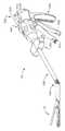
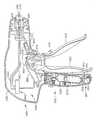
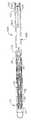
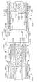
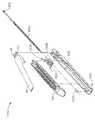
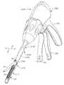
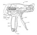
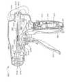
다수 도면 전반에 걸쳐 동일 번호가 동일 구성요소를 지시하고 있는 도면을 참조하면, 도 1은 본 발명의 다수의 고유한 장점을 실현할 수 있는 수술 스테이플링 및 절단 기구(10)를 도시한다. 도 1에 예시된 실시예는 핸들 조립체(300), 세장형 샤프트 조립체(100) 및 세장형 샤프트 조립체(100)에 연결된 엔드 이펙터(12)를 포함한다. 본 발명의 다양한 실시예는 세장형 샤프트 조립체(100)에 피벗이동하게 부착되어 그 내용이 본 명세서에 참조로 통합되어 있는 발명의 명칭이 "관절 엔드 이펙터를 가지는 수술기구"인 2006년 1월 10일자로 출원된 미국 특허 출원 번호 제11/329,020호에 개시된 것들 같은 케이블 또는 밴드를 굴곡시킴으로써 피벗 구동되는 엔드 이펙터를 포함할 수 있다. 그러나, 본 상세한 설명이 진행됨에 따라, 본 기술의 숙련자는 본 발명의 다양한 실시예는 다른 피벗 메커니즘을 사용하는 엔드 이펙터장치과 연계하여 성공적으로 실시될 수 있으며, 추가로 후술하는 바와 같이, 비관절 엔드 이펙터장치와도 성공적으로 사용될 수 있다는 것을 알 수 있을 것이다.Referring to the drawings, wherein like numerals designate like elements throughout the several views, FIG. 1 illustrates a surgical stapling and cutting
도 1에서 볼 수 있는 바와 같이, 기구(10)의 핸들 조립체(300)는 폐쇄 트리거(302) 및 발사 트리거(310)를 포함할 수 있다. 다른 수술 임무에 관련된 엔드 이펙터를 가지는 기구는 다른 수 및 유형의 트리거나 엔드 이펙터를 동작시키기 위한 다른 적절한 제어부를 가질 수 있다는 것을 알 수 있을 것이다. 엔드 이펙터(12)는 바람직하게는 세장형 샤프트 조립체(100)에 의해 핸들 조립체(300)로부터 떨어져 있는 것으로 도시되어 있다. 의사는 관절 제어부(200)를 사용하여 샤프트 조립체(100)에 대하여 엔드 이펙터(12)를 관절 동작시킬 수 있다.As can be seen in FIG. 1, the
수직, 수평, 우측, 좌측 등 같은 공간적 용어는 수술기구의 종축선이 세장형 샤프트 조립체(100)의 중앙축과 동축이고, 트리거(302, 310)가 핸들 조립체(300)의 저면으로부터 예각으로 하향 연장하는 것을 가정하여 도면을 기준으로 여기에 제공된다. 그러나, 실제 실시시, 수술기구(10)는 다양한 각도로 배향될 수 있으며, 따 라서, 이들 공간적 용어는 수술기구(10) 자체에 관련하여 사용된 것이다. 또한, "근위(proximal)"는 핸들 조립체(300) 뒤에 의사가 엔드 이펙터를 의사에게 근접하는 곳에 배치하고, "원위(distal)는 엔드 이펙터(12)를 의사로부터 멀어지게 배치하는 원근법을 지칭하는데 사용된다.Spatial terms such as vertical, horizontal, right, left, etc. are such that the longitudinal axis of the surgical instrument is coaxial with the central axis of the
여기서 사용될 때, 용어 "압축가스"는 무균 환경에서 사용되는 공압 동력식 시스템에 사용하기에 적합한 임의의 가스를 나타낸다. 이런 매체의 비제한적인 예는 압축된 공기, 이산화탄소(CO2), 질소, 산소, 아르곤, 헬륨, 수산화나트륨, 프로판, 이소부탄, 부탄 클로로플루오로카본, 디메틸 에테르, 메틸 에틸 에테르, 질소 산화물, 하이드로플루오로알칸(HFA)-예로서, HFA 134a(1,1,1,2,-테트라플루오로에탄) 또는 HFA 227(1,1,1,2,3,3,,-헵타플루오로프로판) 중 어느 하나를 포함한다.As used herein, the term “compressed gas” refers to any gas suitable for use in pneumatically powered systems used in aseptic environments. Non-limiting examples of such media include compressed air, carbon dioxide (CO2), nitrogen, oxygen, argon, helium, sodium hydroxide, propane, isobutane, butane chlorofluorocarbon, dimethyl ether, methyl ethyl ether, nitrogen oxides, hydro Fluoroalkane (HFA) -e.g., HFA 134a (1,1,1,2, tetrafluoroethane) or HFA 227 (1,1,1,2,3,3, -heptafluoropropane) It includes any one of.
본 명세서에서 사용될 때, 용어 "유체 결합"은 요소가 그 사이에서의 압축가스의 통과를 허용하기 위해 적절한 라인 또는 기타 수단으로 함께 결합되어 있다는 것을 의미한다. 본 명세서에서 사용될 때, "공급라인" 또는 "복귀라인"에서 사용되는 바와 같은 용어 "라인"은 압축가스를 일 구성요소로부터 다른 구성요소로 수송하기 위한 강성 또는 가요성 도관, 파이프, 배관 등으로 형성된 적절한 통로를 지칭한다.As used herein, the term "fluid bond" means that the elements are joined together by suitable lines or other means to allow the passage of compressed gas therebetween. As used herein, the term "line" as used in "supply line" or "return line" refers to rigid or flexible conduits, pipes, piping, etc. for transporting compressed gas from one component to another. Refers to the appropriate passage formed.
본 명세서에서 사용시, 용어 "공압신호" 또는 "공압구동신호"는 함께 유체 결합된 구성요소 사이에서의 가스의 흐름 또는 압축가스의 소스로부터 압축가스의 소스에 유체 결합된 하나 이상의 구성요소로의 가스의 흐름을 지칭한다.As used herein, the term "pneumatic signal" or "pneumatic drive signal" refers to the flow of gas between components fluidly coupled together or gas from a source of compressed gas to one or more components fluidly coupled to a source of compressed gas. Refers to the flow of.
본 명세서에서 사용될 때, "종축선"이 샤프트의 축선인 경우, 어구 "실질적 으로 종축선에 횡단하는"은 종축선에 거의 수직인 방향을 지칭한다. 그러나, 종축선에 수직으로부터 약간 이탈하는 방향도 종축선에 실질적으로 횡단하는 것이다.As used herein, when the "vertical axis" is the axis of the shaft, the phrase "substantially transverse to the longitudinal axis" refers to a direction substantially perpendicular to the longitudinal axis. However, the direction slightly deviating from perpendicular to the longitudinal axis also substantially crosses the longitudinal axis.
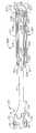
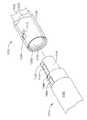
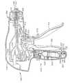
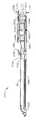
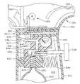
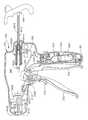
도 2는 본 발명의 다양한 실시예에 사용될 수 있는 공압 동력식 공구 조립체 또는 엔드 이펙터의 한가지 유형의 분해 조립도를 예시한다. 도 1 내지 도 4에 도시된 공압 동력식 공구 조립체(12)는 엔도커터(endocutter)로서 동작하도록 구성되어 있다. 그러나, 본 상세한 설명의 진행에 따라, 본 발명의 실시예의 다양한 고유한, 그리고, 신규한 구동장치가 또한 다른 수술 임무를 수행하도록 구성된 다른 엔드 이펙터를 구동하기 위해 사용되는 것을 고려할 수 있으며, 따라서, 도면에 도시된 바로부터의 구성요소의 제거, 변경 또는 추가를 필요로 할 수 있다. 또한, 도 1 내지 도 4에 도시된 엔드 이펙터(12)는 특정 수술 용례에 맞추어질 수 있다는 것을 알 수 있을 것이다.2 illustrates an exploded view of one type of pneumatic powered tool assembly or end effector that may be used in various embodiments of the present invention. The pneumatically powered
본 발명의 다양한 실시예와 함께 사용될 수 있는 한가지 유형의 엔드 이펙터가 도 2에 도시되어 있다. 도면에서 알 수 있는 바와 같이, 엔드 이펙터(12)는 조직을 절단하고, 내부에 배치된 스테이플 실린더에 위치된 스테이플을 발사하는 것에 부가하여, 유리하게는 스테이플 실린더에 대한 엔드 이펙터(12)의 엔빌 부분의 간격을 제어하는 E-비임 발사 메커니즘("나이프 조립체")(30)을 사용한다. E-비임 발사 메커니즘의 다양한 양태는 관련 부분이 본 명세서에 참조로 통합되어 있는 셀톤 4세 등의 발명의 명칭이 "E-비임 발사 메커니즘을 구비하는 수술 스테이플링 기구"인 미국 특허 제6,978,921호에 설명되어 있다. 그러나, 본 상세한 설명의 진행에 따라, 본 기술의 숙련자는 본 발명의 개념 및 범주로부터 벗어나지 않고, 다른 나이프 및 발사 메커니즘 구조가 유리하게 사용될 수 있다는 것을 알 수 있을 것이다.One type of end effector that can be used with various embodiments of the present invention is shown in FIG. 2. As can be seen in the figure, the
본 명세서에서 사용될 때, 용어 "발사 메커니즘"은 발사 메커니즘이 실질적으로 휴지 상태에 있는 비작동위치로부터 그 부분 또는 부분들이 이동되었거나, 그에 대한 적어도 하나의 발사 동작의 적용에 응답하여 하나 이상의 동작을 완료한 공구에서 이런 그 이동이 초래된 최종 위치로 재배치되어 있는 작동 또는 단부 위치로 이동하는 공압 동력식 공구 및/또는 엔드 이펙터의 부분 또는 부분들을 지칭한다. 발사 메커니즘은 예로서, (i) 수술 장치내의 구성요소와 인터페이스 결합하면서, 공압 동력식 공구에 의해 완전히 지지되어 있는 구성요소, (ii) 수술 장치내에, 그리고, 공압 동력식 공구내에 위치되어 있는 구성요소의 조합, 또는 (ii) 수술 장치에 의해 지지되어서 공압 동력식 공구에 대해 왕복 이동할 수 있는 구성요소를 포함한다. 본원에서 사용되는 용어 "발사행정"은 발사 메커니즘이 비작동위치에서 작동위치로 이동하는 운동을 말한다. 용어 "후퇴행정"은 작동위치로부터 비작동위치로의 발사 메커니즘의 복귀운동을 지칭한다.As used herein, the term “firing mechanism” refers to the completion of one or more actions in response to the application of at least one firing action to or from which a portion or parts of the firing mechanism has been moved from an inoperative position that is substantially at rest. In one tool, it refers to a portion or parts of a pneumatically powered tool and / or end effector that moves to an actuating or end position that has been relocated to the final position resulting in such movement. The firing mechanism is, for example, a configuration that is (i) a component fully supported by a pneumatically powered tool, while interfacing with a component within the surgical device, and (ii) a configuration located in the surgical device and in the pneumatically powered tool. A combination of elements, or (ii) a component supported by a surgical device capable of reciprocating relative to a pneumatically powered tool. The term "stroke stroke" as used herein refers to the movement of the firing mechanism from the inoperative position to the operating position. The term "retraction stroke" refers to the return movement of the firing mechanism from the operating position to the non-operating position.
도 2에서 가장 잘 도시되어 있는 바와 같이, 엔드 이펙터(12)는 다양한 비제한적 실시예에서, 그에 부착된 피벗 병진가능한 엔빌(40)을 가지는 세장형 채널(20)을 포함한다. 세장형 채널(20)은 나이프 조립체(30)에 응답하여 스테이플(70)을 엔빌(40)과의 성형 접촉 상태로 구동하는 스테이플 카트리지(50)를 수용 및 지지하도록 구성된다. 비록, 쉽게 교체가능한 스테이플 카트리지가 유리한 것으로 본 명세서에 설명되었지만, 본 발명의 양태에 따른 스테이플 카트리지는 세장형 채널(20)에 영구 고정되거나 일체화될 수 있다는 것을 유의하여야 한다.As best shown in FIG. 2, the
다양한 실시예에서, 발사 메커니즘 또는 나이프 조립체(30)는 발사 동안 엔드 이펙터(12)의 간격을 제어하는 수직방향으로 이격된 핀을 포함한다. 특히, 상부 핀(32)은 엔빌(40)과 세장형 채널(20) 사이의 피벗 부근에서 엔빌 포켓(42)에 진입하게 된다. 도 4 참조. 엔빌(40)이 폐쇄된 상태에서의 발사시, 상부 핀(32)은 엔빌(40)을 통해 원위 방향으로 연장하는 종방향 엔빌 슬롯(44)내에서 원위방향으로 전진한다. 엔빌(40)의 임의의 미소한 상향 편향은 상부 핀(32)에 의해 부여되는 하향력에 의해 극복된다.In various embodiments, the firing mechanism or
또한, 나이프 조립체(30)는 세장형 채널(20)내에 형성된 채널 슬롯(23)(도 2)과 상향 결합하는 나이프 바아 캡(knife bar cap: 34)을 포함하며, 그에 의해, 그 사이에 과다한 조직이 클램핑된 경우에, 엔빌(40)과 세장형 채널(20)을 미소하게 함께 보다 근접하게 당기도록 상부 핀(32)과 협력한다. 다양한 실시예에서, 나이프 조립체(30)는 세장형 채널(20)의 상향면과 카트리지(50)의 하부면에 형성된 발사 구동 슬롯(미도시)을 통과하는 중간 핀(36)을 포함하고, 그에 의해 후술된 바와 같이, 내부의 스테이플(70)을 구동하는 것이 유리할 수 있다. 중간 핀(36)은 세장형 채널(20)에 대하여 미끄러짐으로써, 유리하게는 그 원위 단부에서 핀치식으로 닫혀지는 엔드 이펙터(12)의 임의의 경향을 유리하게 억제한다. 그러나, 본 발명의 다양한 실시예의 고유하고 신규한 태양은 다른 나이프 조립체 배열의 사용을 통해 얻어질 수 있다.
도 2를 참조하면, 나이프 조립체(30)상에서 상부 및 중간 핀(32, 36) 사이에 원위방향으로 제공된 절단 에지(38)는 클램핑된 조직을 절단하기 위해 카트리 지(50)내의 근위방향에 제공된 수직방향 슬롯(54)을 통해 횡단한다. 세장형 채널(20)과 엔빌(40)에 관한 나이프 조립체(30)의 확실한 위치 설정은 효과적인 절단이 수행되는 것을 보증한다. 다양한 실시예에서, 엔빌(40)의 하부면은 스테이플 카트리지(50)가 세장형 채널내에 수용되어 있을 때, 스테이플 카트리지(50)의 상부면(56)내의 복수의 스테이플 개구(58)에 대응하도록 배열된 복수의 스테이플 성형 포켓(미도시)을 내부에 구비할 수 있다. 다양한 실시예에서, 스테이플 카트리지(50)는 세장형 채널(20)내에 스냅식으로 끼워질 수 있다. 특히, 스테이플 카트리지(50)의 연장형태부(extension feature: 60, 62)는 세장형 채널(20)의 리세스(24, 26)와 각각 마찰 및 해제가능하게 결합한다.With reference to FIG. 2, a
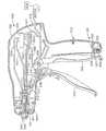
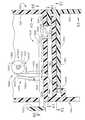
또한, 도 2에서 볼 수 있는 바와 같이, 스테이플 카트리지(50)는 카트리지 본체(51), 웨지 슬레드(64), 스테이플 드라이버(66), 스테이플(70) 및 카트리지 트레이(68)를 포함한다. 조립되었을 때, 카트리지 트레이(68)는 웨지 슬레드(64), 스테이플 드라이버(66) 및 스테이플(70)을 카트리지 본체(51) 내측에 유지한다. 세장형 채널(20)은 세장형 샤프트 조립체(100)에 의해 핸들 조립체(300)에 결합되고, 세장형 샤프트 조립체(100)는 원위 스파인(spine) 또는 프레임 섹션(110)과 근위 스파인 또는 프레임 섹션(130)을 포함한다. 세장형 채널(20)은 원위 스파인 섹션(110)의 원위 단부상에 형성된 대응 채널 고정 부재(114)를 각각 수용하는 원위방향에 배치된 부착 캐비티(22)를 갖는다. 세장형 채널(20)은 또한 엔빌(40)상의 대응 엔빌 피벗(43)을 피벗이동하게 수용하는 엔빌 캠 슬롯(28)을 구비한다. 폐쇄 슬리브 조립체(170)는 스파인 조립체(102) 위에 수용되며, 원위 폐쇄 튜브 세그먼트(180)와 근위 폐쇄 튜브 세그먼트(190)를 포함한다. 후술된 바와 같이, 스파인 조립체(102)에 대한 폐쇄 슬리브 조립체(170)의 축방향 이동은 엔빌(40)이 세장형 채널(20)에 대하여 피벗하게 한다.2, the
도 2에서 볼 수 있는 바와 같이, 로킹(locking) 스프링(112)은 나이프 조립체(30)를 위한 로크아웃(lockout)으로서 원위 스파인 세그먼트(110)에 장착된다. 원위 및 근위 사각형 개구(111, 113)는 그 하부 원위방향 연장 아암(118)이 추가로 상세히 후술될 바와 같이, 나이프 조립체(30)로부터 돌출하는 피스톤 바아 부분(35)을 지지하는 실린더 조립체(501)의 원위 단부상에 하향력을 보조하는 로킹 스프링(112)의 상단 아암(116)을 수용하는 클립 바아(115)를 그 사이에 형성하도록 원위 스파인 세그먼트(110)의 상단부에 형성된다. 다양한 실시예는 다른 유형의 로크아웃을 포함하거나, 로크아웃을 전혀 포함하지 않을 수 있다는 것을 알 수 있을 것이다.As can be seen in FIG. 2, a
도 1 내지 도 6에 도시된 실시예에서, 엔드 이펙터(12)는 피벗(104) 둘레에서 엔드 이펙터(12)를 당기도록 굴곡된 케이블 또는 밴드의 집단에 의해 근위 폐쇄 튜브 세그먼트(190)(그리고, 핸들 조립체(300))에 대하여 관절동작할 수 있다. 본 기술의 숙련자는 이런 배열이 이들 장치의 유형들과 연계하여 사용될 수 있는 다수의 관절 배열 중 단지 하나를 나타내는 것이라는 것을 이해할 수 있을 것이다. 본 실시예에서, 원위 스파인 세그먼트(110)의 근위 단부는 그 위에 돌기(122)를 갖는다. 근위 스파인 세그먼트(130)의 원위 단부는 그를 통한 개구(136)를 구비하는 탱(tang, 134)을 구비한다. 근위 스파인 세그먼트(130)는 개구(136)가 돌기(boss: 122)내의 개구(124)와 동축 정렬되어 피벗 핀(138)이 그를 통해 연장할 수 있게 하도록 원위 스파인 세그먼트(110)에 대하여 배치된다. 도 4 참조. 이런 배열은 조립되었을 때, 엔드 이펙터(12)가 피벗축선 A-A 둘레에서 근위 스파인 세그먼트(130)에 대하여 피벗할 수 있게 한다.In the embodiment shown in FIGS. 1-6, the
상술한 바와 같이, 본 실시예는 엔드 이펙터(12)를 관절동작시키기 위해 밴드(band)를 사용한다. 특히, 밴드(150, 160)는 도 2 및 도 3에 도시된 바와 같이, 관절 피벗(104)을 향해 원위방향으로 연장한다. 밴드(150)는 그 좌측을 따라서 근위 폐쇄 튜브 세그먼트(190)를 통해 연장하며, 여기서, 밴드 부재(160) 둘레로 근위 폐쇄 튜브 세그먼트(190)의 우측으로 횡단하게 된다. 여기서, 밴드(150)는 예로서, 연결점(123)에서 돌기(122)에 기계적으로 결합될 수 있다. 유사하게, 밴드(160)는 그 우측을 따라 근위 폐쇄 튜브 세그먼트(190)를 통해 연장할 수 있으며, 여기서, 밴드 부재(150) 둘레로, 근위 폐쇄 튜브 세그먼트(190)의 좌측으로 횡단한다. 여기서, 밴드(160)는 연결점(125)에서 돌기(122)에 기계적으로 결합될 수 있다.As described above, this embodiment uses a band to articulate the
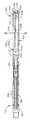
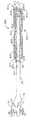
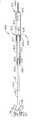
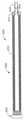
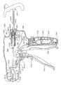
도 3은 폐쇄 튜브 조립체(100)가 가상선으로 도시되어 있는 엔드 이펙터 및 스파인 조립체(102)의 평면도이다. 도 4는 기구(10)의 동일 부분의 부분 측단면도이다. 도 4에서 볼 수 있는 바와 같이, 밴드(150, 160)는 일 비제한적 실시예에 따라 이동의 간섭을 방지하도록 서로 편위된 것으로 도시되어 있다. 예로서, 밴드(150)는 밴드(160) 보다 낮은 위치에 도시되어 있다. 다른 비제한적 실시예에서, 밴드(150, 160)의 수직방향 위치설정은 반전될 수 있다. 또한, 도 2 및 도 3으로부터 알 수 있는 바와 같이, 밴드 부재(150)는 근위 프레임 세그먼트(130)의 탱 부분(134)의 핀(140) 둘레로 연장한다. 마찬가지로, 밴드(160)는 근위 프레임 세그먼트(130)의 탱 부분(134)의 핀(142) 둘레로 연장한다. 또한, 도 2 참조.3 is a top view of the end effector and
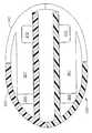
밴드 부분(150, 160)은 돌기(122)로부터, 근위 폐쇄 튜브 세그먼트(190)를 따라 도 5에 도시된 관절 제어부(200)로 연장할 수 있다. 관절 제어부(200)는 관절 슬라이드(202), 프레임(204) 및 수납체(206)를 포함할 수 있다. 밴드 부분(150, 160)은 슬롯(208) 또는 기타 개구에 의해 관절 슬라이드(202)를 통과할 수 있지만, 밴드 부분(150, 160)은 임의의 적절한 수단에 의해 슬라이드(202)에 결합될 수 있다. 관절 슬라이드(202)는 도 5에 도시된 바와 같이 단일 부재일 수 있거나, 일 비제한적 실시예에서, 두 부재 사이의 계면이 슬롯(208)을 형성하는, 두 개의 부재를 포함할 수 있다. 하나의 비제한적 실시예에서, 관절 슬라이드(202)는 예로서 다수의 슬롯을 포함할 수 있으며, 각 슬롯은 밴드 부분(150, 160) 중 하나에 대응한다. 수납체(206)는 이물질 진입을 방지하도록 제어부(200)의 다양한 구성요소를 덮는다.
다양한 실시예에서, 밴드 부분(150, 160)은 슬롯(208)으로부터 근위에 위치된 연결점(210, 212)에서 프레임(204)에 고정될 수 있다. 도 5의 비제한적 실시예는 연결점(210, 212)으로부터 근위 폐쇄 튜브 세그먼트(190)의 종축선 부근에 배치된 슬롯(208)으로 밴드 부분(150, 160)이 예비굴곡되어 있다는 것을 보여 준다. 밴드 부분(150, 160)은 핸들 조립체(300)를 포함하는, 슬롯(208)으로부터 근위에 배 치된 기구(10)의 임의의 위치에 고정될 수 있다.In various embodiments,
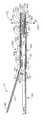
사용시, 도 2의 실시예는 도 3에 도시된 바와 같은 비관절 작동위치를 가질 수 있다. 관절 제어부(200) 및 밴드(150, 160)는 대략 샤프트 조립체(100)의 종축선에 중심설정된 위치에 도시되어 있다. 따라서, 엔드 이펙터(12)는 중립 또는 비관절 작동위치이다. 도 6에서, 관절 슬라이드(202)가 샤프트 조립체(100)의 우측으로 관절 프레임을 통해 추진된 관절 제어부(200)가 도시되어 있다. 따라서, 밴드(150, 160)는 샤프트 조립체(100)의 우측을 향해 굴곡되어 있다. 우측으로의 밴드(150)의 굴곡은 돌기(122)의 피벗점으로부터 편위되어 있는 측방향 지향력을 돌기(122)상에 작용한다는 것을 알 수 있다. 이 편위력은 돌기(122)가 관절 피벗(104) 둘레에서 회전하게 하고, 순차적으로, 엔드 이펙터(12)가 도시된 바와 같이 우측으로 피벗하게 한다. 관절 슬라이드(202)를 샤프트 조립체(100)의 좌측으로 추진하는 것은 샤프트 조립체(100)의 좌측을 향해 양 밴드(150, 160)를 굴곡시키는 측방향 지향력을 밴드(150, 160)상에 작용할 수 있다는 것을 알 수 있을 것이다. 그후, 밴드(160)의 굴곡은 돌기(122)상에 측방향 지향력을 작용하고, 이는 상술된 바와 같이, 돌기(122) 피벗점으로부터 편위되어 있다. 이는 순차적으로, 돌기(122)가 관절 피벗 둘레에서 회전하게 하여, 엔드 이펙터(12)가 좌측으로 피벗하게 한다.In use, the embodiment of FIG. 2 may have a non-joint operating position as shown in FIG. 3.
다양한 실시예에서, 샤프트 조립체(100)는 스파인 조립체(102)상에 수용되어 있는 폐쇄 튜브 조립체(170)로 구성된다. 도 2 참조. 폐쇄 튜브 조립체(170)는 원위 폐쇄 튜브 세그먼트(180) 및 근위 폐쇄 튜브 세그먼트(190)를 포함한다. 원위 폐쇄 튜브 세그먼트(180) 및 근위 폐쇄 튜브 세그먼트(190)는 폴리머 또는 기타 적절한 재료로 제조될 수 있다. 근위 폐쇄 튜브 세그먼트(190)는 중공이며, 내부에 스파인 조립체(102)의 일부를 수용하는 크기로 설정된 관통 연장 축방향 통로(191)를 갖는다.In various embodiments,
도 2 및 도 4에 도시된 실시예에서, 이중 피벗 폐쇄 조인트(172)가 사용된다. 본 발명은 이중 피벗 폐쇄 조인트 디자인에 한정되지 않으며, 임의의 적절한 폐쇄 튜브 또는 슬리브를 포함하거나, 폐쇄 튜브 또는 슬리브를 전혀 포함하지 않을 수 있다는 것을 이해할 것이다. 특히, 도 4를 참조하면, 원위 폐쇄 튜브 세그먼트(180)는 추가로 후술될 바와 같이, 개방 및 폐쇄 위치 사이에서 엔빌(40)을 피벗시키도록 엔빌(40)상의 엔빌 개방/폐쇄 탭(46)과 결합하기 위한 말굽형 개구(horseshoe aperture: 185) 및 탭(186)을 추가로 포함한다. 도 2 참조.In the embodiment shown in FIGS. 2 and 4, a double pivot closing joint 172 is used. It is to be understood that the present invention is not limited to a double pivot closed joint design and may include any suitable closure tube or sleeve or no closure tube or sleeve at all. In particular, with reference to FIG. 4, the distal
근위 폐쇄 튜브 세그먼트(190)는 유사하게, 원위방향 연장 상부 탱(tang: 192) 및 원위방향 연장 하부 탱(194)을 구비한다. 상부 이중 피벗 링크(link: 174)는 상부 근위방향 돌출 탱(182)내의 상부 원위 핀 구멍(183) 및 상부 원위방향 돌출 탱(192)내의 상부 근위 핀 구멍과 각각과 결합하는 상향 돌출 원위 및 근위 피벗 핀(175, 176)을 포함한다. 조인트 배열은 하부 이중 피벗 링크(177)를 추가로 포함하며, 이는 하부 근위방향 돌출 탱(184)내의 하부 원위 핀 구멍(187) 및 하부 원위방향 돌출 탱(194)내의 하부 근위 핀 구멍(195)과 각각 결합하는 하향 돌출 원위 및 근위 피벗 핀(178, 179)(도 2에는 도시되어 있지 않지만 도 4를 참조하라)을 가진다.Proximal
사용시, 폐쇄 튜브 조립체(170)는 예로서, 폐쇄 트리거(310)의 작동에 응답하여 엔빌(40)을 폐쇄하도록 원위방향으로 병진된다. 엔빌(40)은 스파인 조립체(102)상의 폐쇄 튜브 조립체(170)를 원위방향으로 병진시켜 말굽형 개구(185)의 이면이 엔빌(40)상의 개방/폐쇄 탭(46)에 충돌하게 하고, 이를 폐쇄 위치로 피벗하게 함으로써 폐쇄된다. 엔빌(40)을 개방시키기 위해, 폐쇄 튜브 조립체(170)는 스파인 조립체(102)상에서 근위 방향으로 축방향 이동되어 탭(186)이 폐쇄/개방 탭(46)에 대하여 접촉하여 이를 추진하게 하여 엔빌(40)을 개방 위치로 피벗시킨다.In use, the
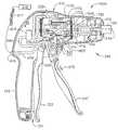
도 7은 본 발명의 다양한 실시예의 비제한적 핸들 조립체(300)의 분해 조립도를 예시한다. 도 7에 도시된 실시예에서, 핸들 조립체는 "피스톨 그립(pistol grip)" 구조를 가지며, 우측 케이스 부재(320) 및 좌측 케이스 부재(330)로 형성되고, 이들은 폴리머(polymer) 또는 다른 적절한 재료로 몰딩되거나 다른 방식으로 제조되며, 함께 정합하도록 설계되어 있다. 이런 케이스 부재(320, 330)는 스냅 특징부, 몰딩 또는 다른 방식으로 성형된 페그 및 소켓 및/또는 접착제, 나사, 볼트, 클립 등에 의해 함께 부착될 수 있다. 우측 케이스 부재(320)의 상부 부분(322)은 좌측 케이스 부재(330)의 대응 상부 부분(323)과 정합하여 주 하우징 부분(340)을 형성한다. 유사하게, 우측 케이스 부재(320)의 하부 그립 부분(324)은 좌측 케이스 부재의 하부 그립 부분(334)과 정합하여 그립 부분(342)을 형성한다. 도 7에 도시된 실시예에서, 전체 그립 부분(342)은 주 하우징 부분(340)과 일체이다. 이런 배열은 특히, 그립 부분(342)내에 압축가스의 소스가 영구적으로 설치되어 있는 용례 에 적합하다. 이런 배열은 또한 핸들 조립체(300)에 대해 외부적이며, 하우징 조립체내의 포트 또는 포트들을 통해 내부에 수납된 제어 구성요소에 플러그 결합되는 압축가스의 소스와 함께 사용하기에도 적합하다. 다른 실시예에서, 추가로 상세히 후술될 바와 같이, 그립 부분(342)은 주 하우징 부분(340)으로부터 분리될 수 있다. 본 상세한 설명의 진행에 따라 인지할 수 있는 바와 같이, 이런 배열은 무수한 이득 및 장점을 제공한다. 그러나, 본 기술의 숙련자는 핸들 조립체(300)가 다양한 다른 형상 및 크기로 제공될 수 있다는 것을 쉽게 알 수 있을 것이다.7 illustrates an exploded view of a
명료성을 위해, 도 7은 궁극적으로 엔빌(40)의 개방 및 폐쇄를 제어하는 폐쇄 튜브 조립체(170)의 축방향 운동을 제어하기 위해 사용되는 구성요소만을 예시한다. 이 도면에서 알 수 있는 바와 같이, 링키지 조립체(430)에 의해 폐쇄 트리거 결합되어 있는 폐쇄 셔틀(400)은 주 하우징 부분(340)내에 지지된다. 폐쇄 셔틀(400)은 또한, 두 부재(402, 404)로 제조되며, 이들은 폴리머 또는 다른 적절한 재료로 몰딩 또는 다른 방식으로 제조되고, 함께 정합하도록 설계되어 있다. 예로서, 도 7에 예시된 실시예에서, 우측 부분(402)은 패스너 포스트(fastener post: 403)를 구비하고, 이는 좌측 부분(404)의 대응 소켓(미도시)내에 수용되도록 설계된다. 우측 및 좌측 부분(402, 404)은 스냅 부재 및/또는 접착제 및/또는 볼트, 나사, 클립 등에 의해 다른 방식으로 함께 유지될 수 있다. 이 도면에서 알 수 있는 바와 같이, 유지 홈(196)이 근위 폐쇄 튜브 세그먼트(190)의 근위 단부에 제공된다. 폐쇄 셔틀(400)의 우측 부분(402)은 우측 유지 플랜지 세그먼트(405)를 가지며, 이는 근위 폐쇄 튜브 세그먼트(190)내의 유지 홈(196)내로 연장하는 유지 플랜 지 조립체를 형성하도록 폐쇄 셔틀(400)의 좌측 부분(404)상의 좌측 유지 플랜지 세그먼트(미도시)와 협력하도록 구성된다.For clarity, FIG. 7 illustrates only the components used to control the axial movement of the
또한, 도 7에서 볼 수 있는 바와 같이, 우측 스파인 조립체 유지 페그(peg: 326)가 우측 케이스 부재(320)로부터 내향 돌출한다. 이런 페그(326)는 폐쇄 셔틀(400)의 우측 부분(402)내의 세장형 슬롯 또는 윈도우(406)내로 돌출한다. 유사한 폐쇄 셔틀(shuttle) 유지 페그(미도시)가 좌측 케이스 부분(330)으로부터 내향 돌출하여 폐쇄 셔틀(400)의 좌측 부분(404)에 제공된 다른 윈도우 또는 슬롯(408)내에 수용된다. 유지 페그는 근위 스파인 세그먼트(130)(도 7에는 미도시)의 근위 단부(133)를 핸들 조립체(300)에 이동 불가하게 고정하면서, 폐쇄 셔틀(400)이 그에 대해 축방향으로 이동하는 것을 허용하도록 기능한다. 유지 페그는 예로서, 볼트, 나사, 접착제, 스냅 형태부 등에 의해 근위 스파인 세그먼트(130)의 근위 단부에 기계적으로 부착될 수 있다. 부가적으로, 폐쇄 셔틀(400)은 측방향 연장 안내 레일(410, 411)을 구비한다. 레일(410)은 우측 케이스 부재(320)내의 레일 가이드(328)내에 활주가능하게 수용되도록 구성되며, 레일(411)은 좌측 케이스 부재(330)내의 레일 가이드(미도시)내에 활주가능하게 수용되도록 구성된다.In addition, as can be seen in FIG. 7, the right spine assembly holding pegs 326 protrude inwardly from the
원위 방향으로의(화살표 "C") 폐쇄 셔틀(400) 및 폐쇄 튜브 조립체(170)의 축방향 이동은 핸들 조립체(300)의 그립 부분(342)을 향한 폐쇄 트리거(302)의 이동에 의해 생성되고, 근위 방향(화살표 "D")으로의 폐쇄 셔틀(400)의 축방향 이동은 그립 부분(342)으로부터 멀어지는 방향으로 폐쇄 트리거(302)를 이동시킴으로써 생성된다. 다양한 실시예에서, 폐쇄 셔틀(400)은 그에 대한 폐쇄 링키지 조립 체(430)의 부착을 용이하게 하는 커넥터 탭(412)을 구비한다. 도 8 및 도 9 참조. 폐쇄 링키지 조립체(430)는 핀(414)에 의해 커넥터 탭(412)에 피벗식으로 고정된 요크(yoke) 부분(432)을 포함한다. 폐쇄 링키지 조립체(430)는 또한 도 7에 예시된 바와 같이, 폐쇄 핀(436)에 의해 폐쇄 트리거(302)상에 형성된 요크 조립체(304)에 피벗식으로 고정된 폐쇄 아암(434)을 구비한다. 폐쇄 트리거(302)는 우측 케이스 부재(320)와 좌측 케이스 부재(330) 사이에서 연장하는 피벗 핀(306)에 의해 핸들 조립체(300)내에 피벗가능하게 장착된다.The axial movement of the closing
의사가 엔빌(40)을 폐쇄하여 엔드 이펙터(12)내에 조직을 클램핑하기를 원할 때, 의사는 그립 부분(342)을 향해 폐쇄 트리거(302)를 당긴다. 의사가 폐쇄 트리거(302)를 그립 부분(342)을 향해 당길 때, 폐쇄 링키지 조립체(430)는 폐쇄 셔틀(400)을 원위 "C" 방향으로 폐쇄 링키지 조립체(430)가 도 8에 도시된 로킹된 위치로 이동할 때까지 이동시킨다. 폐쇄 셔틀(400)이 로킹된 위치로 이동될 때, 폐쇄 튜브 조립체(170)는 스파인 조립체(102)상에서 원위방향으로 이동되어, 엔빌(40)상의 폐쇄/개방 탭(46)이 원위 폐쇄 튜브 세그먼트(180)내의 말굽형 개구(185)의 근위 단부에 의해 접촉되게 하고, 그에 의해, 엔빌(40)이 폐쇄(클램핑된) 위치로 피벗하게 한다.When the surgeon wishes to close the
다양한 실시예에서, 폐쇄 셔틀(400)을 폐쇄 위치에서 추가로 유지하기 위해, 폐쇄 트리거(302)는 해제가능한 로킹 메커니즘(301)을 구비할 수 있으며, 이는 그립 부분(342)과 결합하여 폐쇄 트리거(302)를 로킹된 위치에 해제가능하게 유지하도록 구성된다. 폐쇄 셔틀(400)을 로킹된 위치에 해제가능하게 유지하기 위해, 다 른 로킹 장치도 사용될 수 있다. 도 8, 도 8a, 도 8b 및 도 9에 도시된 실시예에서, 폐쇄 트리거(302)는 그로부터 연장하는 측방향 핀(305)을 포함하는 가요성 종방향 아암(303)을 포함한다. 아암(303) 및 핀(305)은 예로서, 몰딩된 플라스틱으로 이루어질 수 있다. 핸들 조립체(300)의 피스톨 그립 부분(342)은 내부에 측방향 연장 웨지(352)가 배치되어 있는 개구(350)를 포함한다. 폐쇄 트리거(302)가 후퇴될 때, 핀(305)은 웨지(352)와 결합하고, 핀(305)은 웨지(352)의 하부면(354)에 의해 하향 방향으로 힘을 받는다(즉, 아암(303)은 CW로 회전된다). 핀(305)이 하부면(354)을 완전히 지나갈 때, 아암(303)상의 CW 힘은 제거되고, 핀(305)은 CCW로 회전되며, 그래서, 핀(305)은 웨지(352) 배후의 노치부(356)내에 휴지되게 되고, 그에 의해 폐쇄 트리거(302)를 로킹한다. 핀(305)은 또한 웨지(352)로부터 연장하는 가요성 정지부(358)에 의해 로킹된 피스톤내에서 적소에 유지된다.In various embodiments, to further maintain the closing
폐쇄 트리거(302)를 해제하기 위해, 조작자는 폐쇄 트리거(302)를 추가로 압박하여 핀(305)이 개구(350)의 경사진 후방벽(359)과 결합하게 하고, 핀(305)을 가요성 정지부(358)를 지나 상향으로 강제 이동시킨다. 핀(305)은 그후, 개구(360)내의 상부 채널 외부로 이동이 자유로와지고, 그래서, 폐쇄 트리거(302)는 더 이상 피스톨 그립 부분(342)에 로킹되어 있지 않게 된다. 이런 배열의 추가적인 세부 사항은 관련 내용이 본 명세서에 참조로 통합되어 있는 셀톤 4세 등에게 허여된 발명의 명칭이 제거가능한 배터리를 가지는 수술기구인 2006년 1월 31일자로 출원된 미국 특허 출원 제11/344,020호에서 발견할 수 있다. 다른 해제가능한 로킹장치도 사용될 수 있다.To release the
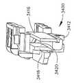
본 발명의 다양한 실시예에서, 나이프 조립체(30)는 그로부터 돌출하는 또는 다른 방식으로 그에 부착된 실질적 강성 피스톤 바아 부분(35)을 구비할 수 있으며, 이는 나이프 조립체(30)에 적어도 두 개의 작동 운동(예로서, 발사운동 및 후퇴운동)을 적용하도록 구성되면서 원위 스파인 세그먼트(110)에 의해 동작가능하게 지지되어 있는 구동부재(500)의 일부이다. 도 3, 도 4, 도 10 및 도 11에 도시된 실시예에서, 구동부재(500)는 2 스테이지 공압 동력식 실린더 조립체(501)를 포함한다. 나이프 조립체(30)는 단일 구성요소를 포함하거나, 이는 기구(10)의 보다 용이한 조립을 촉진하도록 다수의 부재로 제공될 수 있다. 예로서, 도 10 및 도 11에 도시된 바와 같이, 나이프 바아 조립체(30)는 상부 핀(32), 캡(34), 중간 핀(36) 및 나이프(38)를 포함하는 원위 부분(31)을 포함한다. 원위 부분(31)은 피스톤 바아 부분(35)의 원위 단부에 제공된 돌출부(37)를 수용하는 크기로 설정된 개구(33)를 구비할 수 있다. 돌출부(37)는 개구(33)내에 마찰 수용 및/또는 접착제, 용접 등에 의해 내부에 유지될 수 있다.In various embodiments of the invention, the
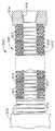
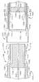
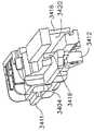
실린더 조립체(501)는 제1 실린더 하우징(510)내의 제1 축방향 통로(516)내로 개방되는 제1 개방 원위 단부(514)와 제1 폐쇄 근위 단부(512)를 가지는 제1 실린더 하우징(510)을 포함한다. 실린더 조립체(501)는 또한 제2 실린더 하우징(520)을 포함하며, 이는 제2 근위 단부(522)와 제2 축방향 통로(526)내로 개방되는 제2 개방 원위 단부(524)를 구비한다. 제2 폐쇄 근위 단부(522)는 그 위에 형성된 제1 피스톤 헤드(528)를 가지며, 이는 제1 피스톤 헤드(528)의 근위 측부와 제1 근위 단부(512)의 원위 측부 사이에 제2 실린더 영역(515)을 형성하도록, 제1 축방향 통 로(516)에 대해 제1 실린더 하우징(510)의 제1 벽(511)과 실질적 기밀 활주 밀봉부를 형성하는 크기로 설정된다. 제1 실린더 하우징(510)의 제1 원위 단부(514)는 제1 피스톤 헤드(528)의 원위 측부와 제1 플랜지(517)의 근위 측부 사이에 제2 실린더 영역(518)을 형성하도록 제2 실린더 하우징(520)의 외부 벽면과 실질적 기밀 활주 밀봉부를 형성하도록 그 위에 형성된 내향 연장 제1 플랜지(517)를 추가로 구비한다.The
제1 통로(527)는 제1 피스톤 헤드(528)를 통해 제공된다. 또한, 도 10 및 도 11에서 볼 수 있는 바와 같이, 피스톤 바아(35)의 근위 단부는 제2 실린더 하우징(520)의 제2 개방 원위 단부(524)(를 통해 제2 축방향 통로(526)내로 연장한다. 제2 피스톤 헤드(530)는 피스톤 바아(35)의 근위 단부에 형성되거나, 다른 방식으로 그에 부착된다. 제2 피스톤 헤드(530)는 제3 실린더 영역(532)을 형성하도록 제2 축방향 통로(526)에 대해 제2 실린더 하우징(520)의 제2 벽(521)과 실질적 기밀 활주 밀봉부를 생성하는 크기로 설정된다. 제2 실린더 하우징(520)의 제2 원위 단부(524)는 또한, 제2 피스톤 헤드(530)의 원위 측부와 제2 플랜지(525)의 근위 측부 사이에 제4 실린더 영역(534)을 형성하도록 피스톤 바아(35)와 실질적 기밀 밀봉부를 형성하도록 그 위에 형성된 내향 연장 제2 플랜지(525)를 추가로 구비한다.
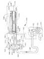
도 3 및 도 4에서 볼 수 있는 바와 같이, 실린더 조립체(501)는 원위 스파인 세그먼트(110)내에 장착된다. 다양한 실시예에서, 한 쌍의 트러니언(trunion)(519)이 제1 실린더 하우징(510)의 근위 단부에 제공된다. 트러니언(519)은 피벗 축 B-B 둘레에서 원위 스파인 세그먼트(110)내에서 실린더 조립체(501)가 회전할 수 있게 하도록 원위 스파인 세그먼트(110)내의 트러니언 보어(119)내에 수용된다. 도 3 참조. 제1 공급라인 또는 공급 도관(540)은 제1 실린더 하우징(510)의 제1 근위 단부(512)내의 개구 또는 제1 공급 포트(513)를 통해 압축가스를 공급하도록 제1 실린더 하우징(510)의 제1 근위 단부(512)에 결합되도록 근위 폐쇄 튜브 세그먼트(190)를 통해 핸들 조립체(300)(도 8 및 도 9)내의 방향 제어 밸브(610)로부터 연장한다. 도 10 및 도 11 참조. 부가적으로, 제2 공급라인(542)은 근위 폐쇄 튜브 세그먼트(190)를 통해 방향 제어 밸브(610)로부터 연장하며, 제2 포트(529)를 통해 제2 실린더 영역(518)내로 압축가스를 공급하도록 그 원위 단부(514)에 인접하게 제1 실린더 하우징(510)에 연결된다.As can be seen in FIGS. 3 and 4, the
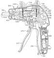
도 8 내지 도 11을 참조하여, 발사 메커니즘 또는 나이프 조립체(30)의 신장 및 수축을 이제 설명한다. 도 8 및 도 9에서 볼 수 있는 바와 같이, 공급라인(540, 542)은 종래의 방향 밸브(610)에 결합되며, 이는 핸들 하우징(350)내에 수납된 작동기 시스템(600)의 일부이다. 다양한 실시예에서, 방향 밸브(610)는 핸들 하우징(350)을 통해 접근할 수 있는 선택기 스위치(612) 또는 푸시 버튼에 의해 전진(연장) 및 반전(후퇴) 위치 사이에서 수동 전환될 수 있다. 도 1 참조. 도 8 및 도 9에 도시된 실시예에서, 압축가스의 제거가능한 소스(620)가 사용된다. 추가로 후술될 바와 같이, 압축가스의 이런 소스는 양호한 압축가스로 교체가능할 수 있는 실린더(622)를 포함한다. 그러나, 본 기술의 숙련자는 교체불가능/재충전가능한 압축가스의 소스(실린더)도 유리하게 사용될 수 있다는 것을 이해할 것이다. 또 다른 실시예에서, 핸들 조립체(300)는 압축가스의 외부 소스(618)로부터 압축가스를 공 급하기 위한 포트(616)를 구비할 수 있다. 예로서, 기구(10)는 가요성 공급라인(617)을 통해 설비의 압축가스 공급부(618)에 연결될 수 있다. 도 8b 참조.8-11, the elongation and retraction of the firing mechanism or
제거가능한/교체가능한 실린더(622)의 고유하고 신규한 양태를 추가로 상세히 후술한다. 그러나, 피스톤 바아(35) 및 나이프 조립체(30)의 신장 및 수축을 설명하기 위해, 종래의 레이트(rate) 밸브(660)를 포함할 수 있는 가변력 작동기내로 공급라인(650)을 통해 실린더(622)(또는 외부 압력 소스(618)로부터 압축가스가 흐르는 것을 볼 수 있다. 특히, 도 9 및 도 55에서 볼 수 있는 바와 같이, 레이트 밸브(660)는 작동 트리거(670)에 부착된 공급 링키지(662)에 결합되어 있다. 여기서 사용될 때, 용어 "가변력 작동 조립체"는 적어도, 레이트 밸브(660)와 작동 트리거(670) 및 그 각각의 등가의 구조체를 포함한다. 다양한 실시예에서, 작동 트리거(670)는 우측 케이스 부재(320)와 좌측 케이스 부재(330) 사이에서 연장하는 피벗 핀(370)에 의해 핸들 조립체(300)에 피벗 결합된 발사 트리거(310)에 인접 지지된다. 작동 트리거(670)를 발사 트리거(310)를 향해 내향 압박하는 것은 레이트 밸브(660)가 실린더(622)로부터 방향 밸브(610)에 결합된 공급라인(680)으로 흐르는 압축가스의 유량을 증가시키게 한다. 방향 밸브(610)의 위치에 따라서, 압축가스는 공급라인(540 또는 542) 중 어느 하나로 유입한다. 예로서, 방향 밸브(610)가 나이프 조립체(30)를 발사하도록 의사에 의해 작동되었을 때, 압축가스는 공급라인(540)을 통해 제1 실린더 영역(515)내로, 제1 피스톤 헤드(528)내의 제1 개구(527)를 통해, 작동 트리거(670) 작동시, 제3 실린더 영역(532)내로 흐를 수 있게 된다. 압축가스가 제3 실린더 영역(532)에 진입하였을 때, 제2 피스톤 헤 드(530)는 피스톤 바아(35)를 원위방향으로 힘을 가한다. 제4 실린더 영역내에 위치된 가스는 그로부터 제2 실린더 하우징(520)내의 배기 개구(523)를 통해 통기된다. 유사하게, 제2 실린더 영역(518)내에 수납된 가스는 제2 개구(529)를 통해 제2 공급라인(542)내로 통기되도록 허용된다. 제2 공급라인(542)은 통기된 가스를 방향 밸브(610)에 전달하고, 이는 궁극적으로 방향 밸브로부터 배기된다. 제1 실린더 영역(515) 및 제3 실린더 영역(532)에 대한 지속적 압축가스의 적용은 나이프 조립체(30)가 엔드 이펙터(12)를 통해 완전히 연장되게 한다. 나이프 조립체(30)가 엔드 이펙터(12)를 통과할 때, 이는 내부에 클램핑된 조직을 절개하고, 스테이플 카트리지(50)내의 스테이플(70)을 발사한다(스테이플을 엔빌(40)의 하부면과 성형 접촉 상태로 구동). 나이프 조립체(30)가 엔드 이펙터(12)내의 그 최원위 위치로 전진되고 나면, 의사는 작동 트리거(670)를 해제함으로써, 압축가스의 적용을 두절시킨다.Unique and novel aspects of the removable /
발사 메커니즘 또는 나이프 조립체(30)를 후퇴시키기 위해, 의사는 수동으로 선택기 스위치(612) 또는 방향 밸브(610)를 제어하기 위한 적절한 버튼을 후퇴 위치로 이동시키고, 작동 트리거(670)를 압박하며, 이는 압축가스가 제2 공급라인(542)으로 흐르게 한다. 제2 공급라인(542)을 통해 흐르는 가스는 제2 실린더 영역(518)에 진입하고, 이는 제2 실린더 하우징(520)이 근위방향으로 제1 실린더 하우징(510)내로 후퇴하게 한다. 제1 실린더 영역(515)내의 가스는 제1 공급 개구(513)를 통해 제1 공급라인(540)내로 통기가 허용된다. 제1 공급라인(540)을 통과하는 가스는 방향 밸브(610)에 진입하고, 이는 이로부터 배기된다. 제2 실린더 영역(518)에 진입하는 압축가스가 제2 실린더 하우징(520)을 도 10에 도시된 바와 같이, 제1 실린더 하우징(510)내로 후퇴시키고 나면, 제2 개구(529)를 통과하는 가스는 이제 제1 실린더 하우징(510)내의 배기 개구(523)를 통해, 제4 실린더 영역(534)으로 통과할 수 있다. 압축가스가 제4 실린더 영역(534)에 진입할 때, 제2 피스톤 헤드(530)는 피스톤 바아(35)를 근위방향으로 제2 실린더 하우징(520)내로 당긴다. 제3 실린더 하우징(532)내의 가스는 제1 개구(527)를 통해 제1 실린더 영역(515)내로 통과하고, 그로부터 이는 상술한 방식으로 배기된다.To retract the firing mechanism or
본 발명의 다양한 실시예의 레이트 밸브(660) 형태의 가변력 작동기는 레이트 밸브(660)를 비작동위치로 편의시키기 위해 스프링 또는 기타 편의 수단(미도시)을 사용할 수 있다. 비작동위치에 있을 때, 레이트 밸브(660)는 밸브(660)내의 오리피스(미도시)를 통한 가스의 소스(620 또는 618)로부터의 가스의 어떠한 흐름도 방지하도록 구성될 수 있다. 작동기 트리거(670)가 비작동위치에 있을 때, 장치는 실질적으로 꺼져 있는 상태이다.The variable force actuator in the form of a
상술한 실시예에서, 레이트 밸브(660)는 의사가 작동 트리거(670)를 발사 트리거(310)를 향해 내향 압박할 때, 링키지 아암(662)이 레이트 밸브(660)가 밸브(660)를 통한 가스의 유량을 증가시킬 수 있게 하도록 공급 링키지 아암(662)에 의해 작동 트리거(670)에 기계적으로 연결될 수 있다. 따라서, 작동 트리거(670)를 신속하게 압박하는 것은 장치의 발사 속도가 증가하게 하고, 작동 트리거(670)가 압박되는 속도를 느리게 하는 것은 발사 속도를 느리게 한다. 따라서, 레이트 밸브(660)를 통해 허용되는 가스 흐름의 양은 실질적으로, 작동 트리거(670)에 인가 된 수동조작 힘의 양에 비례한다.In the above-described embodiment, the
다른 실시예에서, 레이트 밸브(660)는 작동 트리거의 작동시, 레이트 밸브(660)가 그로부터 가스를 디지털적으로 분출하도록 전자 제어될 수 있다. 레이트 밸브(660)는 소량의 가스를 펄스 방식으로 배출하고, 작동 트리거(670)가 압박되는 것이 강하면 강할수록, 펄스는 보다 근접해지게 된다. 이런 배열은 장치를 작동시키기 위해 사용되는 가스의 체적을 선택적으로 규제하도록 기능한다.In another embodiment, the
또한, 또 다른 실시예에서, 작동 메커니즘은 작동 트리거(670)와 같이, 핸들 조립체에 대하여 비피벗식으로 지지되는 다른 유형의 메커니즘을 포함할 수 있다. 예로서, 작동 트리거는 스프링 작동식 슬라이드 스위치 등을 포함할 수 있다. 따라서, 본 발명의 이들 실시예에 제공되는 보호는 피벗 작동식 트리거를 사용하는 실시예에만 한정되지 않는다.Further, in another embodiment, the actuation mechanism may include other types of mechanisms that are pivotally supported relative to the handle assembly, such as
또한, 다양한 실시예에서, 압력 게이지(541)가 도 8 및 도 8a에 도시된 바와 같이 공급라인(540)에 유체 결합될 수 있다. 윈도우(543)가 핸들 조립체(300)의 대응 부분을 통해 제공되어 의사가 게이지(541)를 관찰할 수 있게 하거나, 다른 배열이 사용되어 의사가 사용 도중에 게이지(541)를 관찰할 수 있게 할 수 있다. 도 7 참조. 다양한 실시예에서, 압력 게이지(541)는 전자 동력식 게이지 또는 다이얼 게이지를 포함할 수 있다. 이들 비제한적 실시예에서, 게이지(541)는 발사행정 동안 겪는 힘에 대한 피드백을 제공하기 위한 수단을 제공한다. 본 기술의 숙련자는 특정 비제한적 실시예에서, 발사 메커니즘을 작동시키기 위해 필요한 힘은 실린더 조립체(501)내의 압력에 직접적으로 비례한다는 것을 이해할 것이다. 이들 힘이 작은 경우, 이때, 실린더 조립체(501)는 작동을 위해 큰 압력을 필요로하지 않는다. 다른 한편, 실린더 조립체(501)를 작동시키기 위해 필요한 힘이 큰 경우, 보다 많은 가스가 실린더 조립체(501)내로 방출되어 발사 메커니즘을 완전히 작동시키도록 내부의 압력을 증가시켜야 한다. 압력 게이지(541)는 의사에게 엔드 이펙터가 받고 있는 힘에 대한 비례 판독치(proportionate reading)를 제공한다.Also, in various embodiments,
다른 다양한 실시예에서, 가청 출구(545)가 도 8c에 도시된 바와 같이, 공급라인(540)에 제공될 수 있다. 이런 가청 출구는 공급라인(540)으로부터 소량의 가스가 방출될 수 있게 한다. 압력 힘의 증가에 따라 그 가스의 배출로부터 유발되는 결과적인 휘슬 피치(whistle pitch)가 증가한다. 의사는 그후 휘슬 피치를 발사 메커니즘이 받는 힘에 관련지을 수 있다. 따라서, 이런 배열은 의사에게 구동 시스템(500), 그리고, 궁극적으로는 발사 메커니즘이 받는 발사력을 감시하기 위한 가청 피드백 메커니즘을 제공한다.In other various embodiments, an
다양한 비제한적 실시예는 또한, 발사행정의 단부에 발사 메커니즘이 도달할 때 의사에게 자동 통지하기 위한 수단을 구비할 수도 있다. 예로서, 도 4에 도시된 바와 같이, 리미트스위치(546)는 도 11에 도시된 바와 같이, 발사 로드(35)에 매설 또는 다른 방식으로 부착된 작동 부재(547)를 검출하기 위해 원위 스파인 세그먼트(110)내에 제공될 수 있다. 작동 부재(547)는 발사 바아(35) 및 발사 메커니즘이 발사행정의 단부에 도달할 때 작동 부재(547)가 적절한 신호를 그에 전송하기 위해 방향 제어 밸브(610)에 전기적으로 결합될 수 있는 리미트스위치(546)에 의해 검출되도록 배치된다. 이런 신호의 수신시, 방향 제어 밸브(610)는 자동으로 후퇴 위치 로 이동하고, 발사 메커니즘이 후퇴될 수 있도록 하도록 구성될 수 있다. 부가적으로, 리미트스위치(546)는 도 8에 549로서 도시되어 있는 표시 부재에 결합될 수 있다. 다양한 실시예에서, 표시 부재는 의사에게 발사 메커니즘이 발사행정의 단부에 도달한 것을 나타내는 가청 신호, 시각적 신호 또는 가청 및 시각적 신호의 조합을 제공한다. 예로서, 표시 부재는 음향 발생 장치, LED, 진동 발생 장치 등이나, 이런 장치의 조합을 포함할 수 있다. 리미트스위치 및 관련 제어 구성요소는 하우징 조립체(300)에 지지된 배터리(미도시)에 의해 동력공급될 수 있거나, 이는 외부 전원으로부터 전력을 공급받을 수 있다. 따라서, 본 발명의 다양한 비제한적 실시예는 발사 메커니즘이 발사행정의 단부에 도달하였다는 것을 나타내는 시각적 및/또는 가청 신호를 의사에게 제공하기 위한 수단 및/또는 비작동위치로 발사 메커니즘을 자동 공압식 후퇴시키기 위한 수단을 구비할 수 있다.Various non-limiting embodiments may also include means for automatically notifying the physician when a launch mechanism arrives at the end of the launch stroke. As an example, as shown in FIG. 4, the
도 4, 도 10 및 도 11에서 볼 수 있는 바와 같이, 로킹 돌출부(39)가 피스톤 바아(35)의 저면에 형성될 수 있다. 나이프 조립체(30)가 도 4에 도시된 바와 같이, 완전히 후퇴된 위치에 있을 때, 로킹 스프링(112)의 아암(118)은 실린더 조립체(501)의 원위 단부에 편의력을 인가한다. 실린더 조립체(501)가 트러니언(519)에 의해 원위 스파인 세그먼트(110)내에 피벗식으로 장착되기 때문에, 실린더 조립체(501)의 원위 단부는 원위 스파인 세그먼트(110)내에서 하향 피벗하고, 추가로, 피스톤 바아(35)상의 로킹 돌출부(39)가 세장형 채널(20)내의 로킹 개구(21)내에 들어가게 한다. 이런 배열은 내부에 로킹 개구를 형성하는 세장형 채널(20)의 부분과 로킹 돌출부(39)의 마찰 결합에 의해 후퇴 위치에 나이프 조립체(30)를 로킹하 도록 기능한다. 도 10 및 도 11에서 볼 수 있는 바와 같이, 로킹 돌출부(39)는 세장형 채널(20)내의 로킹 개구에 로킹 돌출부가 쉽게 진입 및 그로부터 벗어날 수 있게 하도록 근위 경사면(39')과 원위 경사면(39")을 구비한다. 본 기술의 숙련자는 다른 나이프 바아 로킹 배열이 본 발명의 범주 및 개념으로부터 벗어나지 않고 성공적으로 사용될 수 있다는 것을 알 수 있을 것이다.As can be seen in FIGS. 4, 10 and 11, a locking
도 12 내지 도 16a는 구동부재(500)가 후술된 차이점을 제외하면 상술한 실린더 조립체(501)와 구조가 유사한 실린더 조립체(800)를 포함하는 본 발명의 다른 실시예를 예시한다. 예로서, 본 실시예에서, 스프링(850, 852)은 피스톤 바아(35)를 후퇴시키도록 사용된다. 도 12 및 도 13에서 볼 수 있는 바와 같이, 실린더 조립체(800)는 제1 폐쇄 단부(812)와 그를 통한 제1 공급 포트(813)를 가지는 제1 하우징(810)을 포함한다. 제1 공급라인(840)은 제1 공급 포트(813)를 통해 압축가스를 공급하도록 제1 폐쇄 단부(812)에 부착된다. 본 실시예에서, 제1 실린더 하우징(810)은 상술된 다양한 실시예와 연계하여 설명된 제2 개구(529)를 갖지 않는다. 제2 실린더 하우징(820)은 제1 실린더 하우징(810)내에 활주가능하게 수용되며, 그 위에 형성된 제1 피스톤 헤드(828)를 가지는 제2 폐쇄 근위 단부(822)를 갖는다. 제1 실린더 영역(815)은 제1 폐쇄 단부(812)와 제1 피스톤 헤드(828) 사이에 형성된다. 제1 후퇴 스프링(850)은 제1 피스톤 헤드(828)와, 제1 실린더 하우징(810)의 원위 단부에 형성된 제1 플랜지(817) 사이에 제공된다. 제1 후퇴 스프링(850)은 제2 실린더 하우징(820)을 도 12에 도시된 바와 같이 제1 실린더(810)내의 후퇴 위치로 편의시키도록 기능한다. 피스톤 바아(35)는 제2 실린더 하우징(820)의 제2 원위 단부(824)에 진입하는 크기로 설정된 단차형 단부(steppde end: 35')를 갖는다. 제2 플랜지(825)는 피스톤 바아(35)의 단차형 부분(35')과 실질적 활주 밀봉부를 달성하도록 제2 원위 단부(824)상에 형성된다. 제2 피스톤 헤드(830)는 제1 피스톤 헤드(828)와 제2 피스톤 헤드(830) 사이에 제3 실린더 영역(832)을 형성하도록 단차형 피스톤 바아 섹션(35')의 근위 단부상에 제공된다. 제1 개구(827)는 제3 실린더 영역(832)과 제1 실린더 영역(815) 사이에서 공기가 통과할 수 있게 하도록 제1 피스톤 헤드(828)를 통해 제공된다. 제2 후퇴 스프링(852)은 도 12에 도시된 바와 같이 제2 실린더 하우징(820)내의 완전히 후퇴된 위치로 단차형 피스톤 바아(35')와 제2 피스톤 헤드(830)를 편의시키도록 도 12에 도시된 바와 같이, 제2 피스톤 헤드(830)와 제2 플랜지(825) 사이에 제공된다.12-16A illustrate another embodiment of the invention in which the
본 발명의 본 실시예는 하기와 같이 동작할 수 있다. 도 16으로부터 볼 수 있는 바와 같이, 핸들 조립체(300)는 상술된 바와 같은 압축가스의 교체가능한 소스(620)를 구비한다. 그러나, 본 기술의 숙련자는 압축가스의 교체불가능 소스(실린더)도 효과적으로 사용될 수 있다는 것을 알 수 있을 것이다. 또 다른 실시예에서, 핸들 조립체(300)는 압축가스의 외부 소스(618)에 대한 방향 제어 밸브(610) 및 관련 구성요소의 부착을 용이하게 하도록 포트(616)를 구비할 수 있다. 도 16a 참조. 예로서, 기구(10)는 가요성 공급라인(617)을 통해 설비의 압축 공기 라인에 결합될 수 있다.This embodiment of the present invention may operate as follows. As can be seen from FIG. 16, the
기구를 동작시키기 위해, 의사는 방향 제어 밸브 선택기 스위치(612)(도 1) 또는 푸시 버튼을 전진(연장) 위치로 이동시키고, 작동 트리거(670)를 압박하기 시 작하며, 이는 압축가스가 실린더(622)(또는 외부 소스(618))로부터 공급라인(680)을 통해, 방향 제어 밸브(610)를 통해, 그리고, 공급라인(840)내로 흐를 수 있게 한다. 압축가스는 제1 공급라인(840)으로부터 제1 공급 포트(813)를 통해 제2 실린더 영역(815)내로, 제1 개구(827)를 통해, 그리고, 제3 실린더 영역(832)내로 흐른다. 제3 실린더 영역(832)에 진입하는 가스는 제2 피스톤 헤드(830) 및 피스톤 바아(35)의 단차형 부분(35')이 원위방향으로 이동되게 한다. 제2 피스톤 헤드(830)가 완전 연장 위치(도 13)로 이동된 이후, 제1 실린더 영역(815)에 계속 진입하는 가스는 제2 하우징(820)을 그 완전 연장 위치로 편의시킨다. 나이프 조립체(30)가 엔드 이펙터(12)내의 그 최원위 위치로 전진되고 나면, 의사는 작동 트리거(670)를 편의시킴으로써 압축가스의 적용을 두절시킨다.To operate the instrument, the surgeon moves the directional control valve selector switch 612 (FIG. 1) or the push button to the forward (extended) position and begins to press the
발사 메커니즘 또는 나이프 조립체(30)를 후퇴시키기 위해, 의사(30)는 방향 밸브 선택기 스위치(612)를 반전(후퇴) 위치로 이동시키고, 여기서, 제1 공급라인(840)이 방향 밸브(610)내의 통기구에 연결된다. 제3 실린더(832)와 제1 실린더 영역(815)내의 가스는 제1 공급 포트(813)를 통해 공급라인(840)내로, 탈출할 수 있게 되고, 궁극적으로는 방향 밸브(610)를 통해 배기된다. 가스가 제3 실린더 영역(832)을 벗어날 때, 제2 후퇴 스프링(853)은 피스톤 바아(35)의 단차형 부분(35')을 제2 실린더 하우징(820)내로 후퇴시킨다. 유사하게, 가스가 제1 실린더 영역(815)을 벗어날 때, 제1 후퇴 스프링(850)은 제2 실린더 하우징(520)을 제1 실린더 하우징(810)내로 편의시킨다.To retract the firing mechanism or
또한, 본 실시예에서, 압력 게이지(541)가 도 16 및 도 16a에 도시된 바와 같이, 공급라인(840)에 유체 결합될 수 있으며, 이는 상술한 방식으로 기능할 수 있고, 엔드 이펙터가 받는 힘에 대한 비례 판독치를 의사에게 제공하는 역할을 한다. 다른 다양한 실시예에서, 가청 출구(audible outlet: 545)가 도 16b에 도시된 바와 같이, 공급라인(840)에 제공될 수 있으며, 이는 구동 시스템(500), 그리고, 궁극적으로는 발사 메커니즘이 받는 발사력을 감시하기 위한 가청 피드백 메커니즘을 의사에게 제공하도록 상술한 방식으로 기능한다. 다른 대안 실시예에서, 발사 메커니즘이 발사행정의 단부에 도달되었다는 것을 나타내는 시각적 및/또는 가청 신호를 제공하고, 및/또는 방향 스위치(610)를 자동 제어하기 위해 발사 로드(35)에 매설된 작동 ㅂw재(547)(도 12 및 도 13)를 검출하기 위해 부리미트스위치(546)(도 15)가 원위 스파인 세그먼트(110)내에 제공될 수 있다.In addition, in this embodiment, the
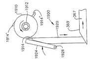
도 17 내지 도 21a는 구동부재(500)가 벨로우즈 조립체(900)를 포함하는 본 발명의 또 다른 실시예를 예시한다. 벨로우즈 조립체(900)는 나이프 바아 조립체(30)의 원위 부분(31)에 부착된 원위 단부(902)를 가질 수 있다. 원위 단부(902)는 부분(31)내의 개구(33)에 수용되는 크기로 설정된 돌출부(904)가 그 위에 형성되어 있다. 돌출부(904)는 개구(33)내에 마찰 수용될 수 있으며, 그리고/또는 접착제, 용접 등에 의해 내부에 유지된다. 원위 부분(31)은 상세히 상술된 바와 같이 구성 및 구축될 수 있다.17-21A illustrate another embodiment of the present invention in which the
벨로우즈 조립체(900)는 연장가능/후퇴가능 벨로우즈 부분(910)을 추가로 포함하며, 이는 도 18에 도시된 바와 같이, 원위 스파인 세그먼트내의 벨로우즈 통로(117)에 대해 신장 및 수축하는 크기로 설정된다. 벨로우즈 부분(910)은 도 20에 도시된 바와 같이, 와이어 수납 링(912)을 갖도록 형성될 수 있으며, 원위 스파인 세그먼트(110)의 일체형 부분을 포함하거나, 원위 스파인 세그먼트(110)에 비가동적으로 부착된 베이스 부분(914)에 부착된다. 베이스(914)는 접착제, 나사 등으로 원위 스파인 세그먼트(110)에 부착될 수 있다. 공급 포트(916)는 벨로우즈 베이스(914)를 통해 제공되고, 공급라인(940)은 공급 포트(916)에 부착된다. 공급라인(940)은 또한, 핸들 조립체(300)의 방향 제어 밸브(610)에 결합된다. 도 21 및 도 21a 참조. 방향 제어 밸브(610)는 또한 진공 라인(922)을 통해 핸들 조립체(300)에 장착된 진공 포트(620)와 교류한다. 진공 포트(620)는 예로서, 가요성 라인(632)에 의해 진공 소스(630)에 부착가능하다. 진공 소스는 설비내의 영구적 진공 공급라인일 수 있다. 가요성 진공 라인(632)은 의사가 기구를 자유롭게 조작할 수 있게 하도록 포트(620)로부터 진공 소스(630)에 부착될 수 있다.The
본 기구는 상술한 폐쇄 튜브 조립체(170) 및 폐쇄 트리거(310) 배열을 구비한다. 따라서, 조직은 상술한 방식으로 엔드 이펙터(12)내에 클램핑될 수 있다. 조직이 엔드 이펙터(12)내에 클램핑된 이후, 의사는 하기와 같이 기구를 발사할 수 있다. 의사는 선택기 스위치(612)(도 1) 또는 방향 제어 밸브(610)를 위한 버튼을 전진(연장) 위치로 이동시키고, 작동 트리거(670)를 압박하기 시작한다. 작동 트리거(670)가 압박될 때, 레이트 밸브(660)는 압축가스가 압력 소스(620)(도 21) 또는 (618)(도 21a)로부터 방향 제어 밸브(610)로 흐르게 한다. 방향 제어 밸브(610)는 벨로우즈(910)내로 공급 도관(940)을 통해 압축가스가 흐를 수 있게 하며, 벨로우즈가 원위방향으로 연장되게 한다. 벨로우즈(910)가 원위방향으로 연장할 때, 이는 엔드 이펙터(12)를 통해 나이프 조립체(30)를 구동하여 내부에 클램핑된 조직을 절단하고, 스테이플 카트리지(50)내의 스테이플(70)을 엔빌(40)의 저면과의 성형 접촉 상태로 구동한다. 나이프 조립체(30)가 엔드 이펙터(12)내의 그 최원위 위치로 구동된 이후, 의사는 작동 트리거(670)를 해제한다. 나이프 조립체(30)를 후퇴시키기 위해, 의사는 방향 제어 밸브(610)를 위한 선택기 스위치(612)를 후퇴 위치로 이동시키고, 그에 의해, 진공 소스(630)가 공급라인(940)에 연결될 수 있게 한다. 공급라인(940)에 대한 진공의 적용은 벨로우즈(910)가 도 18에 도시된 그 후퇴 위치로 후퇴하게 한다. 벨로우즈(910)가 완전히 후퇴된 이후, 의사는 선택기 스위치(612) 또는 버튼을 방향 제어 밸브가 공급라인(940)에 대한 진공의 적용을 중단하는 위치로 이동시킬 수 있다. 그러나, 공급라인(940)내의 잔여 진공은 벨로우즈(910)를 그 후퇴 위치에서 유지하는 역할을 한다.The instrument has the
도 21에 도시된 실시예에서, 제거가능한 압축가스 소스(620)가 사용된다. 추가로 상세히 후술될 바와 같이, 이런 압축가스 소스는 재충전가능한 실린더(622)를 포함한다. 그러나, 본 기술의 숙련자는 압축가스 또는 가압된 유체의 교체불가능/재충전가능 소스(실린더)도 효과적으로 사용될 수 있다는 것을 이해할 것이다. 또 다른 실시예에서, 핸들 조립체(300)는 압축가스를 압축가스의 외부 소스에 공급하기 위한 포트(616)를 구비할 수 있다. 예로서, 기구(10)는 가요성 공급라인(617)을 통해 설비의 압축 공기 라인에 결합될 수 있다. 도 21a 참조.In the embodiment shown in FIG. 21, a removable
또한, 본 실시예에서, 압력 게이지(541)는 도 21 및 도 21a에 도시된 바와 같이, 공급라인(940)에 유체 결합될 수 있으며, 이는 상술한 방식으로 기능할 수 있고, 엔드 이펙터가 받는 힘에 대한 비례 판독치를 의사에게 제공하는 역할을 한다. 다른 다양한 실시예에서, 가청 출구(545)가 도 21b에 도시된 바와 같이, 공급라인(940)에 제공될 수 있으며, 이는 상술한 방식으로, 의사에게 구동 시스템(500), 그리고, 궁극적으로는 발사 메커니즘이 받는 발사력을 감시하기 위한 가청 피드백 메커니즘을 제공하도록 기능한다. 다른 대안 실시예에서, 리미트스위치(546)(도 18)가 방향 스위치(610)를 자동 제어하기 위해 벨로우즈 조립체(900)상의 작동 부재(912')(도 20)를 검출하기 위해, 그리고, 발사 메커니즘 또는 나이프 조립체(30)가 발사행정의 끝에 도달하였다는 것을 나타내는 시각적 및/또는 청각적 신호를 제공하기 위해, 원위 스파인 세그먼트(110)내에 제공될 수 있다.In addition, in this embodiment, the
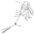
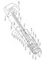
도 22 내지 도 27은 상술한 실시예의 고유하고 신규한 속성 중 다수를 사용하는 비관절식 일회용 엔드 이펙터(12)를 예시한다. 도 23에서 볼 수 있는 바와 같이, 본 실시예는 상술한 임의의 구동부재(600) 및 엔드 이펙터(12)를 사용할 수 있다. 그러나, 본 실시예에서, 엔드 이펙터(12)는 일회용이며, 1000으로서 표시된 신규하고 고유한 신속 분리형 조인트에 의해 근위 샤프트 조립체(1020)에 대해 해제가능하게 분리가능할 수 있는 원위 샤프트 조립체(1010)에 부착된다. 엔드 이펙터(12)가 사용되고 나면, 엔드 이펙터(12) 및 그에 부착된 원위 샤프트 조립체(1010)는 근위 샤프트 조립체(1020)로부터 분리될 수 있고, 필요시 버려진다. 그 자체의 원위 샤프트 조립체(1010) 및 실린더 배열을 완비하는 새로운 무균 엔드 이펙터(12)가 그후 다른 수술 절차를 완료하기 위해 근위 샤프트 조립체(1020)에 부착될 수 있다. 추가로 상세히 후술될 바와 같이, 원위 샤프트 조립체(1010)는 원위 스파인 세그먼트(1110) 및 원위 폐쇄 튜브 세그먼트(1180)를 포함한다. 근위 샤프트 조립체(1020)는 근위 스파인 세그먼트(1150), 근위 폐쇄 튜브 세그먼트(1190) 및 해제 슬리브(1200)를 포함한다.22-27 illustrate a non-articulated
원위 스파인 세그먼트(1110) 및 근위 스파인 세그먼트(1150)는 스파인 조립체(1030)를 형성하도록 협력한다. 본 실시예에서, 원위 스파인 세그먼트(1110)는 그 각각의 근위 단부가 다른 것을 제외하면 상술한 바와 같은, 원위 스파인 세그먼트(110)와 실질적으로 동일할 수 있다. 유사하게, 근위 스파인 세그먼트(1150)는 그 원위 단부가 달라서 원위 스파인 세그먼트(1110) 및 근위 스파인 세그먼트(1150)가 함께 비피벗 결합될 수 있게 한다는 것을 제외하면, 상술한 바와 같은 근위 스파인 세그먼트(130)와 실질적으로 동일할 수 있다. 또한, 본 실시예에서, 원위 폐쇄 튜브 세그먼트(1180)는 그 근위 단부가 다른 것을 제외하면 상술된 근위 폐쇄 튜브 세그먼트(180)와 실질적으로 동일할 수 있다. 유하사게, 근위 폐쇄 튜브 세그먼트(1190)는 그 근위 단부가 달라서, 원위 폐쇄 튜브 세그먼트(1180)와 근위 폐쇄 튜브 세그먼트(1190)가 서로 비피벗 부착될 수 있게 하는 것을 제외하면, 근위 폐쇄 튜브 세그먼트(190)와 실질적으로 동일할 수 있다.
도 23에서 볼 수 있는 바와 같이, 로킹 스프링(112)은 피스톤 바아(35)를 위한 로크아웃으로서 원위 스파인 세그먼트(1110)에 장착된다. 원위 및 근위 사각형 개구(1111, 1113)는 그 원위방향 연장 아암(118)이 상술한 바와 같이, 실린더 조립체의 원위 단부상에 하향력을 보조하는 로킹 스프링(112)의 상부 아암(116)을 수용하는 클립 바아(1115)를 그 사이에 형성하도록 원위 스파인 섹션(1110)의 상단부상 에 형성되어 있다. 다양한 실시예는 다른 유형의 로크아웃을 포함하거나 로크아웃을 전혀 포함하지 않을 수 있다는 것을 알 수 있을 것이다.As can be seen in FIG. 23, locking
원위 스파인 세그먼트(1110)의 근위 단부(1114)는 내부에 형성된 원위 커넥터 부분(1116)을 구비한다. 도 24 및 도 27 참조. 도 24로부터 알 수 있는 바와 같이, 원위 커넥터 부분(1116)은 제1 원위 공급 포트(1117)를 구비하며, 이는 제1 공급라인 세그먼트(540')에 결합된다. 제2 원위 공급 포트(1120)는 원위 커넥터 부분(1116)에 제공되며, 제2 공급라인 세그먼트(542')에 결합된다. 도 23으로부터 알 수 있는 바와 같이, 제1 공급라인 세그먼트(540')는 제1 실린더 하우징(510)내의 제1 공급 포트(513)에 결합되고, 제2 공급라인 세그먼트(542')는 제1 하우징(510)의 원위 단부에서 제2 공급 포트(529)에 결합된다. 제1 공급 노즐 부분(1118)은 도시된 바와 같이, 제1 원위 공급 포트(1117)로부터 근위 방향으로 돌출한다. 제2 공급 노즐 부분(1122)은 제2 공급 포트(1120)로부터 근위방향으로 외향 돌출한다.
유사하게, 근위 스파인 세그먼트(1150)의 원위 단부(1152)는 다른 제1 공급라인 세그먼트(540")에 결합되어 있는 제1 근위 공급 포트(1156)를 갖는다. 제2 커넥터 부분(1154)은 다른 제2 공급라인 세그먼트(542")에 결합된 제2 근위 공급 포트(1160)를 내부에 추가로 구비한다. 제1 근위 공급 포트(1156)는 내부에 제1 공급 노즐(1118)을 제거가능하게 수용하도록 구성되며(도 27), 제2 근위 공급 포트(1160)는 내부에 제2 공급 노즐(1122)을 제거가능하게 수용하는 크기로 설정된다. 도 24 및 도 27에서 볼 수 있는 바와 같이, 제1 O-링 밀봉부(1158)는 제1 노즐(1118)이 제1 근위 공급 포트(1156)내에 삽입될 때, 제1 공급라인 세그먼 트(540')와 다른 제1 공급라인 세그먼트(540") 사이에 실질적 기밀 밀봉부(또는 액밀)를 형성하기 위해 제1 근위 공급 포트(1156)와 연계되어 있다. 이 방식으로 함께 결합되었을 때, 제1 공급라인 세그먼트(540', 540")는 제1 공급라인(540)을 형성하도록 결합된다. 유사하게, 제2 O-링 밀봉부(1162)는 제2 공급 노즐(1122)이 제2 근위 공급 포트(1160)내로 삽입되었을 때, 제2 공급라인 세그먼트(542')와 다른 제2 공급라인 세그먼트(542") 사이에 다른 실질적 기밀(또는 액밀) 밀봉부를 형성하도록 제2 근위 공급 포트(1160)와 연계되어 있다. 이 방식으로 함께 결합되었을 때, 제2 공급라인 세그먼트(542', 542")는 제2 공급라인(542)을 형성한다. 본 기술의 숙련자는 본 발명의 개념 및 범주로부터 벗어나지 않고, 다른 제1 공급라인 세그먼트(540")와 제1 공급라인 세그먼트(540'), 그리고, 다른 제2 공급라인 세그먼트(542")와 제2 공급라인 세그먼트(542')를 제거가능하게 연결하기 위해 다른 분리가능한 결합 배열, 신속 분리 배열이 사용될 수 있다는 것을 이해할 것이다.Similarly, the
원위 커넥터 부분(1116) 및 근위 커넥터 부분(1154)은 그들이 단 하나의 배향으로 함께 결합될 수 있도록 구성될 수 있다. 예로서, 도 24에 도시된 바와 같이, 원위 커넥터 부분(1116)은 설치 동안 제1 노즐(1118)이 제1 근위 공급 포트(1156)에 결합하고, 제2 노즐(1122)이 제2 근위 공급 포트(1160)에 결합하는 것을 보증하도록 근위 커넥터 부분(1154)내의 다른 노치부(1155)와 정합하도록 적용되는 노치부(1119)를 구비할 수 있다. 이런 고유하고 신규한 부착 배열은 제2 근위 공급 포트(1160)에 대한 제1 노즐(1118)의 오부착 및 제1 근위 공급 포트(1156)에 대한 제2 노즐(112)의 오부착을 방지한다. 원위 커넥터 부분(1116)과 근위 커넥터 부분(1154)이 적절한 배향으로 결합되는 것을 보증하도록 다른 키이형 구조가 사용될 수 있다.
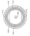
또한, 도 24 및 도 27에서 볼 수 있는 바와 같이, 근위 스파인 세그먼트(1150)의 근위 단부(1152)는 원위방향으로 돌출하는 중공 슬리브 부분(1170)을 가진다. 이런 중공 슬리브 부분(1170)은 내부에 원위 스파인 세그먼트(1110)의 근위 단부(1114)를 수용하는 크기로 설정된다. 근위 스파인 세그먼트(1150)에 대해 원위 스파인 세그먼트(1110)를 해제가능하게 로킹하기 위해, 한 쌍의 대향 디텐트 부재(1124)가 원위 스파인 세그먼트(1110)의 근위 단부(1114)상에 형성된다. 디텐트(1124)는 원위 스파인 세그먼트(1110)의 근위 단부(1114)가 근위 스파인 세그먼트(1150)의 중공 슬리브 부분(1170)에 삽입되고, 제1 노즐(1118)이 제1 근위 공급 포트(1156)에 밀봉 결합되며, 제2 노즐(1122)이 제2 근위 공급 포트(1160)에 밀봉 결합될 때 디텐트 부재(1124)가 중공 슬리브 부분(1170)내의 대응 개구(1172)내에 수용되도록 원위 스파인 세그먼트(1110)내에 절단 또는 다른 방식으로 형성된 가요성 탭(1126)상에 배치된다. 도 24 및 도 27 참조.Also, as can be seen in FIGS. 24 and 27, the
근위 폐쇄 튜브 세그먼트(1190)에 대한 원위 폐쇄 튜브 세그먼트(1180)의 해제가능한 부착을 도 24 내지 도 27을 참조로 설명한다. 이들 도면에서 볼 수 있는 바와 같이, 원위 폐쇄 튜브 세그먼트(1180)의 근위 단부(1182)는 그로부터 근위방향으로 돌출하는 적어도 두 개의 베이어닛형(bayonet-type) 로킹 탭(1184)을 구비한다. 각 로킹 탭(1184)은 근위 폐쇄 튜브 세그먼트(1190)내의 대응 로크 개구(1194)에 수용되는 크기로 설정된 테이퍼형 로킹 웨지(1186)가 그 위에 형성되어 있다. 도 26 및 도 27에 예시된 위치에 있을 때, 원위 스파인 세그먼트(1110)는 근위 스파인 세그먼트(1150)에 로킹되어 스파인 조립체(1130)를 형성하고, 원위 폐쇄 튜브 세그먼트(1180)는 근위 폐쇄 튜브 세그먼트(1190)에 로킹되어 폐쇄 튜브 조립체(1178)를 형성한다. 이런 배열은 상술한 다양한 방식으로 엔드 이펙터(12)상의 엔빌(40)을 개방 및 폐쇄하도록 스파인 조립체(1030)상에서 폐쇄 튜브 조립체(1178)가 근위 및 원위방향으로 이동할 수 있게 한다.Releasable attachment of the distal
원위 샤프트 조립체(1010)를 근위 샤프트 조립체(1020)에 대해 부착하기 위해, 사용자는 원위 샤프트 조립체(1010)의 근위 단부(1012)를 도 24에 도시된 바와 같이 근위 샤프트 조립체(1020)의 원위 단부(1022)와 정렬하고, 그후, 원위 단부(1012)를 근위 단부(1022)내로 삽입한다. 디텐트(1124)가 로킹 개구(1172)내에 수용되고, 로킹 웨지(1186)가 개구(1194)내에 수용되었을 때, 원위 샤프트 조립체(1010)는 근위 샤프트 조립체(1020)에 로킹된다. 엔빌(40)은 폐쇄 트리거(310)를 파지함으로써 원위 방향으로 폐쇄 튜브 조립체(1178)를 이동시키고, 이를 상술한 방식으로, 핸들 조립체(300)의 그립 부분(342)에 대해 피벗시킴으로써 폐쇄된다. 나이프 바아(30)는 상술한 방식으로 작동 트리거(670)를 작동시킴으로써 구동될 수 있다.To attach the
원위 샤프트 조립체(1010)를 근위 샤프트 조립체(1020)로부터 쉽게 분리될 수 있게 하기 위해, 다양한 실시예는 해제 슬리브 배열을 사용한다. 이들 실시예에서, 해제 슬리브 배열(1200)은 근위 폐쇄 튜브 세그먼트(1190)와 원위 스파인 세그먼트(1150) 사이에서 근위 스파인 세그먼트(1150)위에 활주가능하게 저널결합된다. 다양한 실시예에서, 해제 슬리브(1200)의 근위 단부는 근위 폐쇄 튜브 세그먼트(1190)의 근위 단부(1195)내의 대응 슬롯(1196)을 통해 돌출하는 해제 버튼(1204)을 구비할 수 있다. 도 22 및 도 31 참조. 이런 배열은 해제 슬리브(1200)가 스파인 조립체(1030)상의 근위 폐쇄 튜브 세그먼트(1190)의 축방향 이동을 방해하지 않고, 근위 스파인 세그먼트(1150)상에서 원위 및 근위방향으로 축방향 이동되는 것을 허용한다.To enable the
특히, 도 27에서 볼 수 있는 바와 같이, 해제 슬리브(1200)의 원위 단부(1202)는 내향 경사지며, 근위 폐쇄 튜브 세그먼트(1190)내의 두 개의 폐쇄 튜브 로킹 개구(1194)에 인접하도록 배향된다. 원위 샤프트 조립체(1010)를 근위 샤프트 조립체(1020)로부터 해제하기 위해, 사용자는 슬롯(1196)내에서 원위방향으로 해제 버튼을 이동시켜 해제 슬리브(1200)를 원위 방향으로 이동시킨다. 해제 슬리브(1200)의 경사진 원위 단부(1204)가 로킹 웨지(1186)와 접촉할 때, 로킹 웨지(1186)는 근위 폐쇄 튜브 세그먼트(1190)내의 로킹 개구(1194)와의 결합을 벗어나 내향 이동된다. 또한, 원위 방향으로의 해제 슬리브(1200)의 이동은 해제 슬리브(1200)의 제2 경사진 내부 에지(1206)가 로킹 디텐트(1124)와 접촉하고, 이들을 근위 스파인 세그먼트(1150)내의 개구(1172)와의 결합을 벗어나 내향 편의시키며, 그에 의해, 원위 샤프트 조립체(1010)가 근위 스파인 조립체(1020)로부터 분리될 수 있게 한다.In particular, as can be seen in FIG. 27, the
도 22 내지 도 28에 도시된 실시예는 상술한 유형의 실린더 조립체(501)와 효과적으로 함께 사용될 수 있다. 도 29 및 도 30에 도시된 실시예는 상술한 벨로 우즈 조립체(900) 또는 실린더 조립체(800)와 효과적으로 함께 사용될 수 있다. 도 29 및 도 30에서 볼 수 있는 바와 같이, 원위 커넥터 부분(1116)은 내부에 단지 하나의 포트(1300)만이 형성되어 있으며, 이는 공급라인 세그먼트(940')에 결합된다. 제1 공급 노즐(1302)은 도시된 바와 같이, 제1 원위 공급 포트(1300)로부터 근위 방향으로 돌출한다. 유사하게, 커넥터 부분(1154)은 단지 다른 제1 공급라인 세그먼트(940")에 결합된 하나의 근위 공급 포트(1306)만을 갖는다. 근위 공급 포트(1306)는 내부에 제1 공급 노즐(1302)을 제거가능하게 수용하도록 구성된다. 도 29 및 도 30에서 볼 수 있는 바와 같이, O-링 밀봉부(1308)는 공급 노즐(1302)이 근위 공급 포트(1306)에 삽입될 때, 제1 공급라인 세그먼트(940')와 다른 제1 공급라인 세그먼트(940") 사이에서 실질적 기밀 밀봉부(또는 액밀)를 형성하도록 근위 공급 포트(1306)와 연계된다. 이 방식으로 함께 결합될 때, 제1 공급라인 세그먼트(940', 940")는 제1 공급라인(940)을 형성하도록 결합된다. 공급라인(940)은 그후, 상술한 방식으로 실린더 조립체(800) 또는 벨로우즈 조립체(900)에 압축가스를 공급할 수 있다.22-28 can be used effectively with
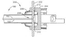
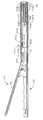
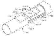
도 32는 상술한 폐쇄 튜브 조립체(170)와 엔드 이펙터(12)와 연계하여 사용될 수 있는 공압 동력식 관절 조인트 조립체(2002)를 가지는 대안적 관절식 수술 절단 및 스테이플링 기구(2000)를 예시한다. 본 실시예는 또한, 상술한 실린더 조립체(501)를 사용한다. 도 33 내지 도 35에서 볼 수 있는 바와 같이, 조인트 조립체(2002)는 그 근위 단부(2012)로부터 돌출하는 피벗 부재(2014)를 가지는 원위 스파인 세그먼트(2010)를 포함하는 스파인 조립체(2004)를 포함한다. 피벗 부 재(2014)는 그로부터 돌출하는 작동기 핀(2016)을 구비한다. 도 35에 도시된 바와 같이, 실린더 조립체(501)는 트러니언(519)상에서 원위 스파인 세그먼트(2010)내에 피벗이동하게 장착된다.32 illustrates an alternative articulated surgical cutting and
피벗 부재(2014)는 근위 스파인 세그먼트(2030)의 원위 단부(2032)상에 형성된 피벗 소켓(2034)내에 피벗이동하게 수용된다. 피벗 부재(2014)는 피벗축선 E-E 둘레에서 근위 스파인 부재(2030)에 대하여 자유롭게 피벗할 수 있다. 도 35에서 볼 수 있는 바와 같이, 근위 스파인 세그먼트(2032)의 원위 단부(2032)는 제1 공급라인(540)의 일부를 수용하도록 내부에 형성된 홈(2036)을 갖는다. 유사하게, 제2 홈(2038)은 내부에 제2 공급라인(542)을 수용하도록 근위 스파인 세그먼트(2030)의 원위 단부(2032)에 제공된다. 공급라인(540, 542)은 피벗 소켓(2034)둘레를 지나 원위 스파인 세그먼트(2010)의 근위 단부(2012)내로 통과하고, 여기서, 이들은 상술한 다양한 방식으로 실린더 조립체(501)에 부착된다. 본 기술의 숙련자는 원위 스파인 세그먼트(2010)가 근위 스파인 세그먼트(2030)에 대해 피벗축선 E-E 둘레에서 자유 피벗할 수 있게 하기 위해, 충분한 이완량이 중공 근위 스파인 세그먼트(2030)내의 공급라인(540, 542)에 제공될 수 있다는 것을 알 수 있을 것이다. 각각 홈(2036, 2038)내에 공급라인(540, 542)을 지지함으로써, 이들 공급라인은 스파인 조립체(2004)에 대한 폐쇄 튜브 조립체(170)의 축방향 이동과 간섭하지 않는다.
또한, 도 35에서 볼 수 있는 바와 같이, 제1 수직 공급 통로(2040)가 피벗 소켓(2034)과 교류하여 제공된다. 유사하게, 제2 수직 공급 통로(2050)도 도 35에 도시된 바와 같이, 피벗 소켓(socket: 2034)과 교류하여 제공된다. 핸들 조립 체(300)에 장착된 스위치 조립체(2100)로부터 연장하는 제3 공급라인(2042)은 제1 수직 공급 통로(2040)와 교류하며, 스위치 조립체(2100)로부터 연장하는 제4 공급라인(2052)은 제2 수직 통로(2050)와 교류한다. 조인트 조립체(2002)를 조립하기 위해, 피벗 부재(2014)가 피벗 소켓(2034)내로 삽입되고, 커버(2060)가 나사(2062) 또는 다른 적절한 고정구로, 도시된 바와 같이, 근위 스파인 세그먼트(2030)에 부착된다. 따라서, 제3 공급라인(2042)으로부터 제1 수직 공급 통로(2040)에 진입하는 압축가스는 원위 스파인 세그먼트(2010)가 "F" 방향으로 피벗축선 E-E 둘레에서 피벗하게 하며, 제4 공급라인(2052)으로부터 제2 수직 공급 포트(2050)에 진입하는 압축가스는 "G" 방향으로 피벗축선 E-E 둘레에서 원위 스파인 세그먼트(2010)가 근위 스파인 세그먼트(2030)에 대하여 피벗하게 한다.Also, as can be seen in FIG. 35, a first
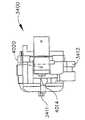
도 37 내지 도 45를 참조하여, 다양한 실시예의 스위치 조립체(2100)의 구성 및 동작을 설명한다. 다양한 비제한적 실시예에서, 스위치 조립체(2100)는 내부에 공급 포트(2112)를 구비하는 스위치 블록(2110)을 포함한다. 공급 포트(2112)는 압축가스의 소스(620)(도 44) 또는 (618)(도 45)로부터 압축가스를 수용하기 위해 공급라인(651)에 결합된다. 특히, 공급라인(651)은 공급라인(650)으로부터 포트(2112)로 연장할 수 있다. 스위치 캐비티(2114)는 스위치 블록(2110)에 제공되며, 내부에 선택기 부재 조립체(2130)의 본체 부분(2150)을 피벗이동하게 수용하는 크기로 설정된다. 피벗 로드(2151)는 스위치 블록(2110)내의 피벗 구멍(2111)에 피벗이동하게 배치되도록 본체 부분(2150)의 저면을 벗어나 돌출한다. 도 39 참조. 이런 배열은 선택기 부재 조립체(2130)가 스위치 축 H-H 둘레에서 선택적으로 회전 되게 한다. 한 쌍의 O-링(2154, 2154) 또는 다른 적절한 밀봉 부재가 도 38 및 도 39에 도시된 바와 같이, 스위치 블록(2110)과 선택기 부재 조립체(2130)의 본체 부분(2150) 사이에 실질적 기밀 밀봉부를 형성하도록 제공될 수 있다. 스템(2156)은 선택기 핸들(2158)을 수용하도록 본체 부분(2150)으로부터 돌출한다. 선택기 핸들(2158)의 회전은 본체 부분(2150)이 스위치 캐비티(2114)내에서 회전하게 한다. 도 39에서 볼 수 있는 바와 같이, 공급 포트(2112)는 역시 스위치 블록(2110)에 형성된 헤더 영역(2118)과 교류하는 스위치 블록(2110)내의 공급 통로(2116)와 교류한다.37-45, the configuration and operation of the
선택기 조립체(2130)의 본체 부분(2150)은 헤더 영역(2118)과 교류하는 그를 통한 중앙 공급 포트(2160)를 갖는다. 제3 공급 통로(2045)는 스위치 블록(2110)내에 제공된다. 도 40 참조. 제3 공급 통로(2045)는 제3 공급라인(2042)이 부착되어 있는 제3 공급 포트(2044)와 스위치 캐비티(2114) 사이에서 연장한다. 유사하게, 제4 공급 통로(2055)는 제4 공급라인(2052)이 부착되어 있는 제4 공급 포트(2054)와 스위치 캐비티(2114) 사이에서 연장하며, 스위치 블록(2110)내에 제공된다. 선택기 부재 조립체(2130)가 도 40에 도시된 바와 같이 배치될 때, 공급 포트(2112)를 통해 공급 통로(2116)로 스위치 블록(2110)에 진입하는 압축가스는 헤더 영역(2118)내로 통과하며, 중앙 공급 통로(2160)내로 흐를 수 있다. 그러나, 압축가스는 중앙 공급 통로(2160)의 단부에서 차단된다. 따라서, 스위치는 도 40의 오프 위치에 있다.The
원위 스파인 세그먼트(2010)를 우측(도 34에 도시된 위치의 반대)로 피벗시 키기 위해서, 선택기 부재 조립체(2130)는 도 41에 예시된 위치로 피벗된다. 이 도면에서 볼 수 있는 바와 같이, 공급 포트(2112)를 통해, 공급 통로(2116)를 통해, 헤더 영역(2118)으로 스위치 블록(2110)에 진입하는 압축가스는 중앙 공급 포트(2160)를 통해, 제3 공급 통로(2045)내로, 그리고, 제3 공급라인(2042)내로 전달된다. 압축가스는 그후 제1 수직 공급 통로(2040)내로 흐르고, "F" 방향으로 피벗 부재(2014)에 힘을 가하도록 피벗 부재(2014)상의 작동기 핀(2016)과 접촉한다. 작동기 핀(2016)의 대향 측부상의 압축가스는 제2 수직 통로(2050)에 진입하고, 제4 공급라인(2052)내로 흐른다. 압축가스가 스위치 블록(2110)내의 제4 포트에 진입할 때, 이는 제4 공급 통로(2055)내로, 그리고, 본체 부분(2150)내의 제4 통기 통로(2170)내로 흐른다. 제4 통기 통로(2170)는 선택기 부재 조립체(2130)의 본체 부분(2150)내의 언더컷(undercut) 통기 영역(2155)과 교류한다. 따라서, 제4 공급라인(2052)내의 압축가스는 제4 통기 통로(2170)를 통해, 언더컷 통기 영역(2155)을 통해 스위치 외부로 배기된다.In order to pivot the
도 34에 도시된 위치로 원위 스파인 세그먼트(2010)를 피벗시키기 위해, 의사는 중앙 공급 통로(2160)가 이제 헤더 영역(2118)과 제4 공급 통로(2055) 사이에서 연장하도록 선택기 부재 조립체(2130)를 회전시킨다. 따라서, 공급라인(651)으로부터 공급 통로(2116)내로, 그리고, 헤더 영역(2118)내로 흐르는 압축가스는 중앙 공급 통로(2160)를 통해 제4 공급 통로(2055)로 흐른다. 압축가스는 제4 공급 포트(2054)를 통해 제4 공급라인(2052)내로 흐른다. 압축가스가 제2 수직 공급 통로(2050)내에 진입할 때, 작동기 핀(2016)은 "G" 방향으로 피벗 부재(2014)를 피벗 시킨다. 도 34 참조. 작동기 핀(2016)의 대향 측부상의 가스는 제 수직 공급 통로(2040)를 통해, 그리고, 제3 공급라인(2042)내로 흐른다. 가스는 제3 공급라인(2042)을 벗어나 제3 공급 통로(2045)내로 흐르고, 본체 부분(2150)에 제공된 제3 통기 통로(2180)내로 흐른다. 제3 통기 통로(2180)는 언더컷 통기 영역(2155)을 통해 외부로 가스를 배기하도록 배향된다.To pivot the
본 실시예의 다른 고유하고 독창적인 형태는 단순히 선택기 스위치 핸들(2158)을 해제시킴으로써, 원하는 관절 작동위치에 원위 스파인 부분(2010)(그리고, 엔드 이펙터(12))을 의사가 로킹할 수 있게 하는 자동 중립 형태 배열(automatic neutral feature arrangement)이다. 보다 구체적으로, 도시된 바와 같이 구성된 복귀 스프링(2190)이 도 40, 도 41 및 도 43에 도시된 바와 같이 스위치 블록(2110)에 장착된다. 스프링(2190)을 스위치 블록(2110)내에 유지하기 위해, 한 쌍의 대향 돌기(2192, 2194)가 스위치 블록(2110)의 저면(2113)으로부터 돌출한다. 스프링(2190)은 각각 돌기(2192, 2194)내의 슬롯(2193, 2195)내에 유지된다. 도 43 참조. 도 43에서 볼 수 있는 바와 같이, 복귀 로드(2153)는 선택기 부재 조립체(2130)의 본체 부분(2150)으로부터 돌출한다. 복귀 로드(2153)는 복귀 스프링(2190)의 자유 단부(2196, 2198) 사이에 수용된다. 도 43은 중립 또는 폐쇄 위치의 본체 부분(2150)을 예시한다.Another unique and inventive form of the present embodiment is the automatic release of the
따라서, 의사가 엔드 이펙터(12)를 관절 작동시키기를 원할 때, 그 또는 그녀는 선택기 핸들(2158)을 회전시켜 원하는 관절 이동에 대응하는 회전방향으로 선택기 부재 조립체(2130)의 본체 부분(2150)을 이동시킨다. 의사가 본체 부분(2150) 을 회전시킬 때, 이는 복귀 스프링(2190)의 자유 단부(2196, 2198) 중 하나에 의해 생성된 힘에 대항하여 회전된다. 의사가 엔드 이펙터(12)를 원하는 위치로 관절 작동시키고나면, 그 또는 그녀는 선택기 핸들(2168)을 해제하고, 복귀 스프링(2190)은 본체 부분(2150)을 폐쇄 위치로 이동시키며, 이는 엔드 이펙터(12)를 그 위치에 유지한다. 의사가 엔드 이펙터(12)의 관절 작동위치를 조절하기를 원하는 경우, 그 또는 그녀는 원하는 위치를 획득하기 위해 원하는 방향으로 선택기 핸들(2158)을 회전시키고, 그후, 그 위치에서 엔드 이펙터(12)를 유지하도록 핸들(2158)을 해제하기만 하면 된다.Thus, when the surgeon desires to articulate the
도 44는 본 발명의 다양한 비제한적 실시예를 위한 스위치(2100)와의 접속에 사용되는 제어 시스템 구성요소의 배열을 예시한다. 도면에서 볼 수 있는 바와 같이, 압축가스의 제거가능한 소스(620)가 사용된다. 소스(620)로부터 흐르는 가스는 공급라인(650)을 통해 레이트 밸브(660)로, 그리고, 공급라인(651)을 통해 스위치 조립체(2100)의 포트(2112)로 흐른다. 도 44에 도시된 실시예에서, 소스(620)는 교체가능한/재충전가능한 캐니스터(canister: 622)를 포함하며, 이는 하우징 조립체(300)의 그립 부분(342)에서 지지된다. 실린더(622)는 재충전가능할 수 있다. 그러나, 본 기술의 숙련자들은 압축가스의 교체불가능/재충전가능 소스(실린더)도 효과적으로 사용될 수 있다는 것을 알 수 있을 것이다. 또 다른 실시예에서, 핸들 조립체(300)는 압축가스의 외부 소스(618)로부터 압축가스의 공급을 위해 포트(616)를 구비할 수 있다. 예로서, 기구는 가요성 공급라인(617)을 통해, 설비의 압축된 공기 라인(미도시)에 결합될 수 있다. 도 45 참조.44 illustrates an arrangement of control system components used in connection with a
도 46 내지 도 48은 상술한 유형 및 구조의 급속 분리 조인트(1000')와 연계한 관절 조인트 조립체(2002) 배열의 사용을 예시한다. 그러나, 이 배열에서, 총 4개 포트가 사용되었다. 도 47에서 볼 수 있는 바와 같이, 원위 커넥터 부분(1116)은 제1 공급라인 세그먼트(540')에 결합된 제1 원위 공급 포트(1117)를 갖는다. 제2 원위 공급 포트(1120)는 원위 커넥터 부분(1116)에 제공되며, 제2 공급라인 세그먼트(542')에 결합된다. 제1 공급 노즐 부분(1118)은 도시된 바와 같이, 제1 원위 공급 포트(1117)로부터 근위 방향으로 돌출한다. 제2 공급 노즐 부분(1122)은 제2 공급 포트(1120)로부터 원위 방향으로 외부로 돌출한다.46-48 illustrate the use of an articulation
원위 커넥터 부분(1116)은 제3 공급라인 세그먼트(2042')에 결합된 제3 원위 공급 포트(1117')를 추가로 갖는다. 제4 원위 공급 포트(1120')는 원위 커넥터 부분(1116)에 제공되고, 제4 공급라인 세그먼트(2052')에 결합된다. 제3 공급 노즐 부분(1118')은 도시된 바와 같이, 제3 원위 공급 포트(1117')로부터 근위 방향으로 돌출한다. 제4 공급 노즐 부분(1122')은 제4 공급 포트(1120')로부터 근위 방향으로 외부로 돌출한다.
유사하게, 근위 스파인 세그먼트(1150)의 원위 단부(1152)는 제1 공급라인 세그먼트(540")에 결합된 제1 근위 공급 포트(1156)를 가지는 제2 커넥터 부분을 구비한다. 제2 커넥터 부분(1154)은 다른 제2 공급라인 세그먼트(542")에 결합된 제2 근위 공급 포트(1160)를 내부에 추가로 구비한다. 제1 근위 공급 포트(1156)는 내부에 제1 공급 노즐(1118)을 제거가능하게 수용하도록 구성되며, 제2 근위 공급 포트(1160)는 내부에 제2 공급 노즐(1122)을 제거가능하게 수용하는 크기로 설정된 다. 도 47에서 알 수 있는 바와 같이, 제1 O-링 밀봉부(1158)가 제1 노즐(1118)이 제1 근위 공급 포트(1156)내로 삽입될 때, 제1 공급라인 세그먼트(540')와 다른 제1 공급라인 세그먼트(540") 사이의 실질적 기밀 밀봉부(또는 유체 밀봉)를 형성하기 위해 제1 근위 공급 포트(1156)와 연계되어 있다. 이 방식으로 함께 결합될 때, 제1 공급라인 세그먼트(540', 540")는 제1 공급라인(540)을 형성하도록 결합된다. 유사하게, 제2 O-링 밀봉부(1162)가 제2 공급 노즐(1122)이 제2 근위 공급 포트(1160)에 삽입될 때, 제2 공급라인 세그먼트(542')와 다른 제2 공급라인 세그먼트(542") 사이에 다른 실질적 기밀(또는 유체-밀봉) 밀봉부를 형성하기 위하여 제2 근위 공급 포트(1160)와 연계되어 있다. 이 방식으로 함께 결합될 때, 제2 공급라인 세그먼트(542', 542")는 제2 공급라인을 형성한다.Similarly,
부가적으로, 근위 스파인 세그먼트(1150)의 원위 단부(1152)는 다른 제3 공급라인 세그먼트(2042")에 연결되어 있는 제3 근위 공급 포트(1156')를 갖는 제2 커넥터 부분(1154)을 구비한다. 제2 커넥터 부분(1154)은 다른 제4 공급라인 세그먼트(2052")에 결합된 제4 근위 공급 포트(1160')를 내부에 추가로 구비한다. 제3 근위 공급 포트(1156')는 내부에 제3 공급 노즐(1118')을 제거가능하게 수용하도록 구성되며, 제4 근위 공급 포트(1160')는 내부에 제4 공급 노즐(1122')을 제거가능하게 수용하는 크기로 설정된다. 도 47에서 볼 수 있는 바와 같이, 제3 O-링 밀봉부(1158')는 제3 노즐(1118')이 제3 근위 공급 포트(1156')에 삽입될 때, 제3 공급라인 세그먼트(2042')와 다른 제3 공급라인 세그먼트(2042") 사이에 실질적 기밀 밀봉부(또는 유체 밀봉)를 형성하기 위해 제3 근위 공급 포트(1156')와 연계되어 있다. 이 방식으로 함께 결합될 때, 제3 공급라인 세그먼트(2042', 2442")는 제3 라인(2042)을 형성하도록 결합된다. 유사하게, 제4 O-링 밀봉부(1162')는 제4 공급 노즐(1122')이 제4 근위 공급 포트(1160')에 삽입될 때, 제4 공급라인 세그먼트(2052')와 다른 제4 공급라인 세그먼트(2052") 사이에 다른 실질적 기밀(또는 유체 밀봉) 밀봉부를 형성하도록 제4 근위 공급 포트(1160')와 연계된다. 이 방식으로 함께 결합될 때, 제4 공급라인 세그먼트(2052', 2052")는 제4 공급라인(2052)을 형성한다. 본 기술의 숙련자들은 다른 분리가능한 결합 배열, 급속 분리 배열이 본 발명의 범주를 벗어나지 않고 사용될 수 있다는 것을 이해할 수 있을 것이다.Additionally, the
배경 기술 부분에서 상술한 바와 같이, 엔도커터 시스템은 점점 더 작아지고 있기 때문에, 필요한 구동력을 생성할 수 있는 공압 동력식 시스템의 개발에 대한 과제가 점점 더 커지고 있다. 이런 문제점은 회전 구동 샤프트를 구동하기 위해 전기 모터를 사용함으로써 해결이 다소 용이하게 되었다. 회전 운동은 긴 가요성 또는 관절식 구동 사프트에 걸쳐 쉽게 전달될 수 있다. 비록, 전기 모터 크기 및 토크 성능에 대하여 방대한 연구가 이루어져 왔지만 이런 시스템의 효율은 원위 샤프트 직경의 크기와, 스테이플링 메커니즘에 가능한 근접해지는 모터를 위한 영역에 끼워질 수 있는 모터의 크기에 의해 제한된다. 다수의 현재 용례에서, 샤프트 직경의 소정 크기는 시스템을 구동하기 위해 충분한 에너지를 제공하면서, 전기 모터가 시스템의 원위 단부에 위치되지 못하게 한다.As described above in the background section, because end-cutter systems are becoming smaller and smaller, the challenge for the development of pneumatically-powered systems capable of generating the required driving force is growing. This problem is somewhat easier to solve by using an electric motor to drive the rotary drive shaft. Rotational motion can be easily transmitted over long flexible or articulated drive shafts. Although extensive research has been made on electric motor size and torque performance, the efficiency of such a system is limited by the size of the distal shaft diameter and the size of the motor that can fit into the area for the motor as close as possible to the stapling mechanism. . In many current applications, a certain size of shaft diameter provides sufficient energy to drive the system, while preventing the electric motor from being located at the distal end of the system.
하기의 실시예는 이런 문제점 및 전기 구동 모터의 사용과 연계된 단점을 해결한다. 후술될 바와 같이, 이들 실시예는 회전 구동식 엔도커터에 회전 동력을 전 달하기 위해 공압 동력식 모터를 사용한다. 공압 동력식 모터는 일반적으로, 모터에 전달되는 가스의 압력 및 체적에 비례하는 분당 회전 및 토크를 생성한다. 도 49 내지 도 56에 도시된 비제한적 실시예에서, 관절식 구동 샤프트 조립체가 공압 동력식 모터로부터 엔드 이펙터에 회전 운동을 전달하기 위해 사용된다. 그러나, 본 기술의 숙련자는 본 발명의 이들 실시예의 고유하고 신규한 양태는 또한 엔도 커터에 회전 구동 운동을 전달하기 위한 가요성 구동 샤프트 배열을 사용하는 임의의 다른 수술기구 및 다른 공지된 회전 구동식 엔드 이펙터와 연계하여 효과적으로 사용될 수 있다는 것을 이해할 것이다. 부가적으로, 본 발명의 이들 실시예의 고유하고 신규한 양태는 비관절식 엔드 이펙터장치와 연계하여서 효과적으로 사용될 수 있다.The following examples solve this problem and the disadvantages associated with the use of an electric drive motor. As will be discussed below, these embodiments use pneumatically powered motors to transfer rotational power to a rotationally driven endocutter. Pneumatically powered motors generally produce revolutions per minute and torque proportional to the pressure and volume of gas delivered to the motor. In the non-limiting embodiment shown in FIGS. 49-56, an articulated drive shaft assembly is used to transmit rotational motion from the pneumatically powered motor to the end effector. However, those skilled in the art will appreciate that the unique and novel aspects of these embodiments of the present invention also include any other surgical instruments and other known rotationally driven arrangements that employ a flexible drive shaft arrangement for transmitting rotational drive motion to the endo cutter. It will be appreciated that it can be effectively used in conjunction with end effectors. In addition, unique and novel aspects of these embodiments of the present invention can be effectively used in conjunction with non-articulated end effector devices.
도 49 내지 도 56은 회전 구동식 엔도커터(1512)를 사용하는 본 발명의 수술 절단 및 스테이플링 기구(1500)를 예시한다. 다양한 회전 구동식 엔도커터 및 기타 수술기구가 존재한다. 예로서, 한가지 이런 엔도커터 배열은 관련 부분이 본 명세서에서 참조되고 있는 Shelton IV 등의 2006년1월 31일자로 출원된 발명의 명칭이 "적응성 사용자 피드백을 구비한 모터 구동식 수술 절단고정기구"인 미국 특허 출원 제11/343,447호에 개시되어 있다. 다른 예는 관련 부분이 본 명세서에서 참조되어 있는 Shelton IV 등의 2006년 6월 27일자로 출원된 발명의 명칭이 "수동 구동 수술 절단고정기구"인 미국 특허 출원(KLNG 번호 050704/END5779USPN)에 개시되어 있다.49-56 illustrate the surgical cutting and
도 50은 다양한 비제한적 실시예에 따른 엔드 이펙터(1512)의 분해도이다. 예시된 실시예에 도시된 바와 같이, 엔드 이펙터(1512)는 공압 동력식 공구를 수용하는 크기로 설정된 세장형 채널(1520)을 포함할 수 있다. 다양한 비제한적 실시예의 공압 동력식 공구는 내부에 "발사 메커니즘"을 작동가능하게 지지하는 스테이플 카트리지(50)를 포함한다. 본 실시예는 웨지 슬레드 조립체(1530)를 포함하며, 이는 그 위에 나이프 부분(1538)을 포함한다. 웨지 슬레드 조립체(1530)는 나선형 구동 스크류(1560)상으로 나사결합된다. 세장형 채널(1520)의 원위 단부(1521)에 배치된 베어링(1522)은 나선형 구동 스크류(1560)를 수용하여 나선형 구동 스크류(1560)가 세장형 채널(1520)에 관하여 자유 회전할 수 있게 한다. 나선형 구동 스크류(1560)는 구동 스크류(1560)의 회전이 웨지 슬레드 조립체(1530)가 카트리지에 지지된 스테이플이 완전히 발사된 전체 연장 또는 작동위치와 완전 후퇴 위치 또는 비작동위치 사이에서 세장형 채널(1520)을 통해 원위 방향 또는 근위 방향으로(회전 방향에 따라) 병진하게 하도록 웨지 슬루 조립체(1530)의 나사식 개구(미도시)와 인터페이스 결합할 수 있다. 따라서, 나선형 구동 스크류(1560)가 일 방향으로 회전될 때, 웨지 슬레드 조립체(1530)는 카트리지(50)를 통해 원위방향으로 구동되어 엔드 이펙터(1512)내에 클램핑된 조직을 절단하고, 세장형 채널(1520)에 피벗 결합된 엔빌(40)의 저면과 성형 접촉 상태로 카트리지(50)내의 스테이플을 발사한다. 웨지 슬레드 조립체(1530)의 슬레드 부분(1532)은 예로서, 플라스틱으로 이루어질 수 있으며, 경사진 원위면(1534)을 가질 수 있다. 웨지 슬레드 조립체(1530)가 세장형 채널(1520)을 횡단할 때, 경사진 전방면(1534)은 클램핑된 조직을 통해 스테이플 카트리지(50)내의 카트리지를 엔빌(40)에 대하여 추진 또는 구동 한다. 엔빌(40)은 스테이플을 회전시키고, 꺽어지게 하고, 그에 의해 절단된 조직을 스테이플링한다. 웨지 슬레드 조립체(1530)가 후퇴될 때, 나이프 부분(1538) 및 슬레드 부분(1532)은 분리되고, 그에 의해, 세장형 채널(1520)의 원위 단부에 슬레드 부분(1532)을 남긴다. 본 기술의 숙련자는 다른 발사 메커니즘을 갖는 다른 공압 동력식 공구가 사용될 수 있다는 것을 알 수 있을 것이다.50 is an exploded view of
도 51 및 도 52는 핸들 조립체(300)내의 공압 구동 모터로부터 나선형 구동 스크류(1560)로 회전 운동을 전달하기 위한 한가지 구동 샤프트 배열을 예시한다. 도 51을 참조로 알 수 있는 바와 같이, 본 실시예는 상술한 폐쇄 튜브 조립체(170)를 사용할 수 있다. 폐쇄 튜브 조립체(170)는 기어(1552, 1554, 1556)를 포함하는 베벨 기어 조립체(1550)를 경유하여 보조(또는 원위) 구동 샤프트(1546)와 교류하는 주 회전(또는 근위) 구동 샤프트(1544)를 회전가능하게 지지하는 근위 스파인 세그먼트(1542)를 포함하는 스파인 조립체(1540)상에 활주가능하게 수용된다. 보조 구동 샤프트(1546)는 나선형 구동 스크류(1560)의 근위 구동 기어(1562)와 결합하는 구동 기어(1548)에 연결된다. 수직 베벨 기어(1552)는 근위 스파인 세그먼트(1542)의 원위 단부의 개구(1543)내에 피벗 지지된다. 원위 스파인 세그먼트(1570)는 보조 구동 샤프트(1546) 및 구동 기어(1548, 1554)를 수납하도록 사용된다. 총체적으로, 주 구동 샤프트(1544), 보조 구동 샤프트(1546) 및 관절 조립체(예로서, 베벨 기어 조립체(1550))는 때때로, 본 명세서에서 "주 구동 샤프트 조립체"라 지칭된다.51 and 52 illustrate one drive shaft arrangement for transferring rotational motion from the pneumatic drive motor in the
도 53 및 도 54에서 알 수 있는 바와 같이, 기구(1500)의 다양한 실시예는 압축가스(620) 형태의 공압 동력 소스에 의해 동력공급된다. 이들 도면에 도시된 실시예에서, 소스(620)는 하우징 조립체(300)의 그립 부분(642)내에 지지된 교체가능한/재충전가능한 캐니스터(622)를 포함한다. 실린더(622)는 재충전가능할 수 있다. 그러나, 본 기술의 숙련자는 압축가스의 교체불가능/재충전가능 소스(실린더)도 효과적으로 사용될 수 있다는 것을 알 수 있을 것이다. 또 다른 실시예에서, 핸들 조립체(300)는 압축가스의 외부 소스(618)로부터 압축가스를 공급하기 위한 포트(616)를 구비할 수 있다. 예로서, 기구(1500)는 가요성 공급라인(617)을 통해 설비의 압축 공기 라인(미도시)에 결합될 수 있다. 도 53A 참조.As can be seen in FIGS. 53 and 54, various embodiments of the
제거가능/재충전가능 실린더(622)의 고유한, 그리고, 신규한 양태를 추가로 상세히 후술한다. 그러나, 엔드 이펙터(1512)에 회전 운동을 제공하기 위한 구동 시스템을 설명하기 위해, 압축가스는 실린더(622)로부터, 또는 외부 압력 소스(618)로부터 공급 도관(650)을 통해, 종래의 레이트 밸브(660)로 압력하에 흐른다는 것을 알 수 있다. 레이트 밸브(660)는 작동 트리거(670)에 부착된 공급 링키지(662)에 결합되어 있다. 도 53 및 도 58 참조. 다양한 실시예에서, 작동 트리거(670)는 우측 케이스 부재(320)와 좌측 케이스 부재(330) 사이에서 연장하는 피벗 핀(370)에 의해 핸들 조립체(300)에 피벗 연결된 이동 감시 부재 또는 상대 위치 발사 트리거(310')에 인접하게 지지된다. 상대 위치 트리거(310')는 플라스틱 또는 다른 적절한 재료로 제조될 수 있으며, 도시된 바와 같이, 작동 트리거(670)를 수용하도록 실질적인 U-형상 단면을 갖는 부분을 구비한다. 의사는 그 하부 세 개의 손가락이 상대 위치 트리거(310')상에 존재하고 그 엄지 손가락이 작동 트리 거(670)상에 존재하도록 의사의 손을 하우징 조립체(300)의 그립 부분(352)상에 위치시킬 수 있다. 상대 위치 트리거(310')를 향해 내향으로 작동 트리거(670)를 압착하는 것은 레이트 밸브(660)가 소스(620)(또는 도 53A에서는 618)로부터 방향 제어 밸브(1610)내로의 공급라인(680)내로, 압력하에 가스가 통과할 수 있게 한다.Unique and novel aspects of the removable /
도 56에서 볼 수 있는 바와 같이, 방향 제어 밸브(1610)는 전방 위치 섹션(1620), 정지 섹션(1630) 및 반전 섹션(1640)을 갖는다. 제어 밸브 섹션(1620, 1630, 1640)은 핸들 하우징(300)을 통해 돌출하는 푸시 버튼(1612, 1614)에 의해 수동 이동될 수 있다. 도 49 및 도 56을 참조하라. 두 개의 공급/배기 라인(1700, 1710)은 방향 제어 밸브(1610)로부터 종래의 공압 동력식 모터(1730)로 연장한다. 따라서, 의사가 제어 밸브(1610)를 전진 위치로 이동시킬 때, 전진 통로(1622)가 압축가스가 공급라인(680)으로부터 그리고, 공급/배기 라인(1700)내로 흐르게 하여, 공압 구동 모터(1730)가 제1 방향으로 모터 구동 샤프트(1732)를 구동하게 하고, 이는 추가로 상세히 후술될 바와 같이, 발사행정의 엔드 이펙터(1512)를 통해 원위 방향으로 웨지 슬레드 조립체(1532) 및 나이프 부분을 구동하는 구동 샤프트(1544)로의 회전 운동의 전달을 초래한다. 공급라인(1710)을 통해 공압 동력식 모터(1730)를 벗어나는 가스는 통기 포트(1632)를 통해 배기된다. 제어 밸브(1610)가 반전된 위치로 이동될 때, 공급라인(680)을 통과하는 가스는 공급라인(1710)을 통해 공압 동력식 모터(1730)내로 흐를 수 있게 된다. 공급/배기 라인(1700)을 통해 공압 동력식 모터(1730)를 벗어나는 가스는 통기 포트(1632)를 통해 배기된다. 제어 밸브가 정지 위치에 있을 때, 공급라인(1680) 및 공급/배기 라인(1710)은 폐 쇄되고, 공급라인(1700)은 통기 포트(1632)에 연결된다. 도 56 참조.As can be seen in FIG. 56, the
또한, 도 56에서 볼 수 있는 바와 같이, 공압 동력식 모터(1730)의 출력 샤프트(1732)는 그 위에 제1 구동 기어(1743)를 가질 수 있으며, 이는 유성 기어 조립체(1740)의 입력 샤프트(1738)에 장착된 제2 구동 기어(1736)와 맞물림 결합한다. 유성 기어 조립체(1740)는 종래의 샤프트 결합 부재(1743)에 의해 구동 샤프트(1544)의 근위 단부(1545)에 그에 회전 운동을 전달하도록 결합된 출력 샤프트(1742)를 갖는다. 따라서, 제어 밸브(1610)가 전진 위치로 이동될 때, 공압 동력식 모터(1730)의 출력 샤프트(1732)는 기어(1734, 1736) 및 유성 기어 조립체(1740)를 통해 구동 샤프트(1544)에 회전 운동을 부여하여 웨지 슬레드 조립체(1530) 및 나이프 부분(1538)이 카트리지(50)를 통해 구동되어 엔드 이펙터(1512)내에 클램핑된 조직을 절단하고, 카트리지(50)내의 스테이플을 엔빌(40)과 성형 접촉상태로 구동하게 한다. 제어 밸브(1610)가 반전 위치로 이동될 때, 공압 동력식 모터(1730)의 출력 샤프트(1732)는 구동 샤프트(1544)에 반대방향 회전 운동을 부여하여 웨지 슬레드 조립체(1530) 및 나이프 부분(1538)이 다시 카트리지(50)를 통해 근위 방향으로 후퇴되게 한다.Also, as can be seen in FIG. 56, the
도 49 내지 도 56에 도시된 실시예는 기구의 동작성을 향상시키고, 카트리지(50)내의 웨지 슬레드 조립체(1530) 및 나이프 부분(1538)이 내부에서 원위방향으로 전진되고 또한 후퇴될 때, 그 위치를 의사가 감시할 수 있도록 의사에게 다양한 피드백의 형태를 제공하는 다른 고유하고 신규한 특징을 갖는다. 다시 도 56으로 돌아가서, 피드백 기어(1750)가 유성 기어 조립체(1740)의 출력 샤프트(1742) 또는 구동 샤프트(1544)상에 제공된다는 것을 볼 수 있다. 피드백 기어(1750)는 나사식 나이프 위치 샤프트(1754)상에 장착된 나이프 위치 기어(1752)와 맞물림 접촉한다. 나이프 위치 샤프트(1754)는 내부에서의 그 자유 회전을 촉진하는 적절한 베어링 배열(미도시)에 의해 지지된다. 근위 리미트스위치(1760)는 샤프트(1754)의 근위 단부(1756)와 연계되고, 원위 리미트스위치(1770)는 샤프트(1754)의 원위 단부(1758)와 연계된다. 나이프 지시기(1780)가 그 위에서 원위 및 근위 방향으로 이동하도록 나이프 위치 샤프트(1754)상에 나사결합된다. 구동 샤프트(1544)가 웨지 슬레드 조립체(1530) 및 나이프 부분(1538)이 카트리지(50)를 통해 원위방향으로 이동되게 하는 방향으로 회전될 때, 나이프 지시기(1780)는 또한 원위 리미트스위치(1770)를 향해 근위방향으로 이동한다. 원위 리미트스위치(1770)는 웨지 슬레드(1530) 및 나이프 부분(1538)이 최원위 위치에 있을 때, 나이프 지시기(1789)가 원위 리미트스위치(1770)를 작동시키도록 배향된다. 의사가 그 발사행정내의 발사 메커니즘(웨지 조립체(1530) 및 나이프 부분(1538)의 위치를 결정하기 위해 나이프 지시기(1780)의 위치를 관찰할 수 있고, 또한, 의사에게 후퇴행정 동안 웨지 조립체의 위치를 감시하기 위한 수단을 제공하도록 좌측 케이스 부재(330)(또는 하우징 조립체(300)내의 나이프 위치 샤프트(1754)의 위치에 따라 우측 케이스 부재(320))에 윈도우가 제공된다.49-56 improves the operability of the instrument and, when the
또한, 다양한 실시예에서, 원위 파일럿(pilot) 라인이 공급라인(650)으로부터 원위 리미트스위치(1770)로 제공될 수 있다. 원위 리미트스위치 라인(1774)은 원위 리미트스위치(1770)와 방향 제어 밸브(1610) 사이에 제공될 수 있다. 따라서, 웨지 슬레드 조립체(1530) 및 나이프 부분(1538)이 발사행정을 완료하고, 나이프 지시기(1780)가 원위 리미트스위치(1770)를 작동시킬 때, 원위 리미트스위치(1770)는 가스가 공급라인(650)으로부터 원위 리미트스위치 라인(1774)으로, 그리고, 방향 제어 밸브(1610)내로 압력하에 흐를 수 있게 하며, 이는, 다양한 실시예에서, 방향 제어 밸브(1610)가 자동으로 반전 위치로 이동되게 하고, 그에 의해, 공압 동력식 모터(1730)가 반전되게 하고, 궁극적으로, 구동 샤프트(1544)에 반전 회전 운동을 부여한다. 공압 동력식 모터(1730)가 구동 샤프트(1544)를 반전시킬 때, 반전 회전 운동은 나이프 위치 샤프트(1754)에 전달되고, 그에 의해, 나이프 위치 지시기(1780)를 다시 근위 리미트스위치(1760)를 향해 구동한다. 또한, 나이프 위치 지시기(1780)가 근위 리미트스위치(1660)를 작동시킬 때(웨지 슬레드(1530) 및 나이프 부분(1538)이 그 완전 후퇴 위치로 이동된 것을 의미함) 근위 리미트스위치(1660)가 그후 가스가 근위 리미트스위치 라인(1664)내로, 그리고, 방향 제어 밸브(1610)내로 흐를 수 있게 하여, 방향 제어 밸브(1610)가 자동으로 정지 위치로 이동되게 하도록 근위 리미트스위치(1660)와 공급라인(650) 사이에서 근위 파일럿 라인(1662)이 연장한다.Further, in various embodiments, a distal pilot line may be provided from
다양한 실시예에서, 제1 공기 동력식 휘슬(17980) 또는 기타 적절한 음향 발생 장치가 원위 리미트스위치 라인(1774)(또는 원위 리미트스위치(1770))과 교류할 수 있으며, 그래서, 원위 리미트스위치(1770)가 발사행정의 단부에서 작동될 때, 원위 리미트스위치 라인(1774)을 통과하는 공기가 제1 휘슬(1790)을 작동시켜, 의사에게 발사행정의 단부에 웨지 슬레드/나이프가 도달되었다는 것을 나타내는 가청 신호를 제공한다. 유사하게, 제2 공기 동력식 휘슬(1792) 또는 다른 적절한 음향 발생 장치가 근위 리미트스위치(1760)와 교류하여, 근위 리미트스위치(1760)가 후퇴행정의 단부에서 작동될 때, 근위 리미트스위치 라인(1764)을 통과하는 공기가 제2 휘슬(1792)을 작동시켜 의사에게 웨지 슬레드/나이프가 후퇴행정의 단부에 도달하였다는 것을 나타내는 다른 가청 신호를 제공한다. 다른 실시예에서, 예로서, 배터리 동력식 발광 다이오드 또는 다른 신호 장치가 원위 및 근위 리미트스위치(1770, 1760)와 교류하여 웨지 슬레드/나이프가 발사행정 및/또는 후퇴행정의 단부에 도달하였을 때 사용자에게 다른 지표를 제공할 수 있다. 대안 실시예에서, 휘슬(1790, 1792)은 장치가 발사행정 및/또는 후퇴행정의 끝에 도달하였을 때를 나타내기 위한 압력 센서 또는 게이지로 교체될 수 있다.In various embodiments, the first pneumatic whistle 17980 or other suitable acoustic generator may be in communication with the distal limit switch line 1774 (or distal limit switch 1770), and thus, the distal limit switch 1770. ) Is operated at the end of the firing stroke, air passing through the distal
도 49 내지 도 56에 도시된 다양한 실시예에서, 공압 구동 모터는 핸들 조립체(300)내에 지지된다. 도 52a 및 도 52b에 도시된 실시예에서, 공압 동력식 모터(1730')가 원위 스파인 섹션(110)내에 배치된다. 모터 구동 샤프트(1546)는 그 위에 구동 기어(1548')를 가지며, 이는 나선형 구동 스크류(1560)의 근위 구동 기어(1562)와 맞물림 결합한다. 도 52a는 상술된 바와 같은, 관절 조인트(104)와 연계하여 이런 원위 장착 공압 동력식 공기 모터를 도시한다. 도 52b에 도시된 실시예는 상술한 바와 같은 공압 동력식 관절 조인트 조립체(2002)를 사용한다. 이런 원위 장착식 공기 모터 배열은 또한 엔드 이펙터가 그것이 부착되는 세장형 샤프트 조립체의 부분 또는 핸들 조립체에 대하여 관절 동작하지 않는 기구와 연계하여 사용되거나 다른 관절 조인트 배열을 사용하는 수술기구와 연계하여 사용될 수도 있 다. 본 기술의 숙련자는 이런 원위 장착 공압 동력식 모터 배열이 모터가 핸들 조립체에 지지되고, 발사 및 후퇴운동이 관절 조인트를 통해 엔드 이펙터로 전달되어야만 하는 실시예를 위한 세장형 구동 샤프트 배열에서 발생할 수 있는 동력 손실을 최소화한다. 도 52a 및 도 52b에 도시된 것과 같은 실시예는 단지 모터(1730')에 대한 동력 공급을 위해 단지 두 개의 라인(1710, 1760)만이 관절 조인트를 통과하면 된다. 라인(1710, 1760)은 가요성 배관 등을 포함할 수 있으며, 하나 이상의 구동부재가 관절을 통과하여야 하는 다른 배열에 비해, 관절 조인트를 덜 제한한다.In various embodiments shown in FIGS. 49-56, a pneumatic drive motor is supported in the
또한, 본 발명의 다양한 실시예는 기구의 발사 구성요소의 상대 위치에 관한 촉각적 형태의 피드백을 사용자에게 제공하도록 구성될 수 있다. 소정 실시예에서, 이는 이동 감시 부재 또는 상대 위치 트리거(310')를 장치의 구동 샤프트 또는 발사 메커니즘에 적용되는 전진 및 후퇴운동에 연동시킴으로써 달성된다. 보다 구체적으로, 그리고, 도 53 내지 도 55를 참조하면, 본 실시예는 다양한 비제한적 실시예에서, 상대 위치 트리거(310')의 상부 부착판 부분(332)에 회전가능하게 장착된 너트 부재(334)에 나사결합하도록 부착된 나사식 수동 피드백 샤프트(1801)를 포함할 수 있는 피드백 링키지 조립체(1800)를 포함할 수 있다. 수동 피드백 샤프트(1801)의 원위 단부는 나이프 위치 기어(1752)와 맞물림 결합하는 수동 피드백 기어(1804)를 지지하는 만능 조인트 부분(1802)을 갖는다. 방향 제어 밸브(1610)가 전진 위치에 있을 때, 공압 동력식 모터(1730)는 웨지 슬레드(1750) 및 나이프 부분(1538)의 형태의 발사 메커니즘이 실린더를 통해 원위방향으로 구동되도록(발사 행정) 구동 샤프트(1544)를 구동한다. 피드백 기어(1750)는 나이프 위치 기어(1752)를 구동하고, 이는 순차적으로, 수동 피드백 기어(1804)를 구동한다. 수동 피드백 기어(1804)는 그후 수동 피드백 샤프트를 회전시키고, 이는 너트(334)와의 그 나사 결합에 의해, 이는 상대 위치 트리거(310')를 핸들 조립체(300)의 그립 부분(342)을 향해 당기며, 그에 의해, 웨지 슬레드(1530) 및 나이프 부분(1538)의 전진의 "촉각적" 지표를 의사에게 제공한다. 본 기술의 숙련자는 의사가 핸들 조립체(300)의 그립 부분(342)을 향해 상대 위치 트리거(310')를 피복시키기를 시도하는 경우, 수동 피드백 샤프트(1801) 및 너트(334)는 그 임의의 이동을 방지한다는 것을 이해할 것이다. 그러나, 상대 위치 트리거(310')는 웨지 슬레드(1530) 및 나이프 부분(1538)의 전진 및 후퇴에 관하여 자동 피벗한다. 이런 배열은 의사에게 수술 절차 전반에 걸쳐 상대 위치 트리거(310')를 단순히 파지함으로써, 웨지 슬레드 조립체(1530) 및 나이프 부분(1538)(발사 메커니즘)의 전진 및 후퇴의 자동 촉각적 지표를 제공한다. 따라서, 의사는 이런 피드백을 획득하기 위해, 어떠한 것도 주시할 필요가 없다. 이런 배열은 의사에게 비작동위치와 작동된 위치 사이의 발사 메커니즘의 진행에 대한, 또한, 발사 메커니즘이 작동된 위치로부터 비작동위치로 복귀 이동할 때, 한 손 비시각적 피드백을 제공한다.In addition, various embodiments of the present invention may be configured to provide a user with tactile form feedback regarding the relative position of the firing component of the instrument. In certain embodiments, this is accomplished by linking the movement monitoring member or relative position trigger 310 'to forward and backward movements applied to the drive shaft or launch mechanism of the device. More specifically, and referring to FIGS. 53-55, the present embodiment, in various non-limiting embodiments, includes a nut member rotatably mounted to the upper
또한, 다양한 실시예는 도시된 다른 촉각적 피드백 배열(333)을 구비할 수 있다. 예로서, 도 53 내지 도 56에서 볼 수 있는 바와 같이, 상대 위치 트리거(310')의 상부 부착판 부분(332)은 일련의 슬롯(335), 디텐트(detent), 홈 등을 구비할 수 있으며, 이들은 상대 위치 트리거(310')가 발사행정 및 후퇴행정 동안 핀(370) 둘레에서 상대 위치 트리거(310')가 피벗할 때, 핸들 조립체(300)내에 장착된 스프링 아암(337)과 인터페이스 작용하도록 설계되어 있다. 상부 부착판 부분(332)이 상대 위치 트리거(310')와 함께 피벗할 때, 스프링 아암(337)의 단부는 각 연속적 슬롯(335)내로 떨어지며, 상부 부착판 부분(332)에 (일련의) 힘을 부여하도록 기능하며, 상기 힘은 상대 위치 트리거(310')를 파지할 때, 의사가 느낄 수 있다. 따라서, 상대 위치 트리거(310')가 전진할 때, 의사는 상대 위치 트리거(310')(그리고, 궁극적으로는 발사 메커니즘)가 발사행정 동안 전진하거나, 후퇴행정 동안 후퇴되는 중이든지 그것이 어느 경우인지를 확인하도록 발사 메커니즘의 이동에 대응하는 일련의 부가적인 촉각적 피드백을 제공받는다. 부가적으로, 스프링 아암(337)의 단부가 각 연속적 슬롯내로 떨어질 때, 이는 가청 음향, 클릭음 등을 생성하여 의사에게 발사행정 및 후퇴행정을 통한 발사 메커니즘의 이동에 관한 청각적 피드백을 제공할 수 있다. 따라서, 본 실시예는 일련의(적어도 두 개의) 가청 음향을 제공하며, 이들은 비작동 및 작동위치 사이의 발사 메커니즘의 이동에 관한 것이다.In addition, various embodiments may have other
본 기술의 숙련자는 기구(1500)가 종래의 공압 동력식 엔도커터 배열에 비해 방대한 개선을 나타낸다는 것을 알 수 있을 것이다. 예로서, 다양한 실시예는 그 발사행정을 통해 구동될 때, 발사 메커니즘(웨지 슬레드/나이프)의 위치를 의사가 감시할 수 있게 하는 수단을 제공한다. 소정 실시예에서, 웨지 슬레드/나이프가 그 발사행정의 끝에 도달할 때, 이는 자동으로 후퇴된다. 완전 후퇴 위치에 도달하고 나면, 제어 밸브는 정지 위치로 자동 스위칭될 수 있으며, 그에 의해, 소스(618 또 는 620)로부터 공압 동력식 모터(1730)로의 공기의 공급을 중단시킨다. 그러나, 작동 프로세스 동안, 의사가 실린더내에서 원위방향으로의 웨지 슬레드/나이프의 전진을 정지시키기를 원하는 경우, 그 또는 그녀는 간단히 제어 밸브(1610)를 반전 위치로 수동 스위칭하고, 웨지 슬레드/나이프가 원하는 후퇴 위치로 이동될 때까지 공압 동력식 모터(1730)에 압축가스를 공급하도록 작동 트리거(670)의 작동을 계속할 수 있다. 또한, 고유하고 신규한 상대 위치 트리거(310')는 의사에게 상대 위치 트리거(310')를 잡고 있는 동안 의사가 느낄 수 있는 수동 또는 촉각적 피드백을 제공한다. 또한, 의사는 웨지 슬레드/나이프가 발사행정의 단부에 도달 및/또는 완전히 후퇴되었을 때, 가청 신호를 제공받을 수 있다.Those skilled in the art will appreciate that
또한, 본 기술의 숙련자는 이동 감시 장치에 의해 제공되는 고유하고 신규한 장점은 이들 구동부재의 전진 및 후퇴가 직접적으로 또는 간접적으로 상대 위치 트리거(310')에 연동되도록 푸시/풀 가요성 케이블(미도시) 또는 강성 부재(비관절식 실시예를 위해)에 의해 구동부재 각각을 상부 부착판 부분(332) 또는 상대 위치 트리거(310')의 다른 부분에 연결함으로써 구동부재(500, 800) 또는 벨로우즈 조립체(900)를 사용할 때에도 얻어질 수 있다. 이 고유하고 신규한 배열은 또한 후술된 도 70 내지 도 80에 도시된 실시예와 함께 사용될 수도 있다.Furthermore, those skilled in the art will appreciate the unique and novel advantages provided by the movement monitoring device that push / pull flexible cables (such as the forward and backward movements of these drive members directly or indirectly engage relative position trigger 310 ').
상술한 바와 같이, 피드백 링키지 조립체(1800)는 발사 메커니즘의 진행을 감시하기 위한 수단을 의사에게 제공하도록 발사 메커니즘의 이동 속도에 대응하는 속도로 상대 위치 트리거(310')를 자동으로 이동시킬 뿐만 아니라, 피드백 링키지 조립체(1800)는 의사가 상대 위치 트리거(310')를 수동 피벗시킬 수 없게 하거나 이를 현저히 제한하는 나사 또는 기타 수단을 사용할 수 있다. 이런 비제한적 실시예에서, 상대 위치 트리거(310')가 이동하는 유일한 시기는 피드백 링키지 조립체가 이를 이동시킬 때이다. 또 다른 실시예에서, 상대 위치 트리거(310')의 수동 이동은 작동시 상대 위치 트리거(310')의 임의의 피벗 이동을 방지하도록 구성된 모터(미도시) 또는 다른 가스 실린더(미도시)에 의해 방지될 수 있다. 예로서, 작동 트리거(670)상의 힘의 존재는 가스의 방출을 활성화하지만, 발사 메커니즘이 이동하기 시작할 때까지, 상대 위치 트리거(310')는 현저한 이동이 불허되며, 발사 메커니즘은 이동이 중단되고, 그래서, 상대 위치 트리거(310')의 이동도 중단된다.As noted above, the
그러나, 다른 다양한 실시예에서, 피드백 링키지 조립체(1800)는 의사가 필요로 하는 경우, 발사 메커니즘의 전진을 지연시키거나, 그에 힘을 추가하도록 발사행정 동안 공압 동력 모터(1740) 형태의 구동부재를 보조하는 기능을 제공하도록 구성될 수 있다. 이들 다양한 실시예에서, 예로서, 피드백 샤프트(1801)가 극점-형(acme-type) 나사 또는 기타 나사 배열이나 의사가 상대 위치 트리거(310')에 압력을 실제로 인가할 수 있게 하여, 너트(334)와의 그 결합에 의해 샤프트(1801)에 회전력을 부여할 수 있게 하는 구조로 형성될 수 있다. 샤프트(1801)에 회전 운동을 부여함으로써, 의사는 또한 구동 샤프트(1544)에 저널 결합된 기어(1750)와 맞물림 결합하는 기어(1804)에 회전력을 인가한다. 따라서, 발사 메커니즘이 저항을 받는 경우, 의사는 상대 위치 트리거(310')를 압착함으로써, 구동 샤프트(1544)에 기계적으로 발생한 동력을 인가할 수 있다. 의사가 발사 메커니즘의 이동을 저속화 또는 지연시키기를 원하는 경우, 의사는 상대 위치 트리거(310')에 힘을 인가할 수 있으며, 이는 순차적으로, 샤프트(1801) 및 기어(1804)의 회전을, 그리고, 궁극적으로는 구동 샤프트(1544)의 회전을 저지/저속화한다.However, in other various embodiments, the
상술한 다양한 실시예는 장치를 동작시키기 위해 압력하의 가스를 공급하기 위한 제거가능한 실린더(622)의 사용과 연계하여 설명되었다. 다양한 실시예에서, 제거가능한 실린더(622)는 최초에 압력하의 가스로 충전 및 재충전 가능하다. 다른 실시예에서, 실린더는 재충전 가능하지 않을 수 있다. 예로서, 실린더(622)는 이산화탄소가 충전된 종래의 일회용 실린더를 포함할 수 있다. 실린더가 비워지고 나면, 사용자는 이를 핸들 조립체로부터 제거하고, 이를 새로운 충전된 실린더와 교체한다. 사용될 수 있는 다른 유형의 가스는 예로서, 압축 공기, 이산화탄소(CO2), 질소, 산소, 아르곤, 헬륨, 수산화나트륨, 프로판, 이소부탄, 부탄, 클로로플루오로 카본, 디메틸에테르, 메틸에틸에테르, 질소 산화물, 하이드로플루오로알칸(HFA) 이다. 이런 배열은 종래의 공압 동력식 수술기구 배열에 비해 현저한 개선을 제공한다. 그러나, 기구가 사용될 수 있는 횟수는 장치의 무균성의 효과적인 유지에 대한 필요성과, 이런 실린더에 저장될 수 있는 가스의 체적에 의존한다.The various embodiments described above have been described in connection with the use of a
본 발명의 다른 실시예는, 저장 압력에 있을 때, 비가스성, 액체 상태 물질을 저장하고, 그 후, 액체의 적어도 일부가 장치의 작동으로 보다 낮은 압력하에 배치될 때 가스 상태로 증발하는 실린더(622)를 사용한다. 이들 실시예에 사용될 수 있는 이들 액체의 예는 실소 산화물, 디메틸에틸 에테르, 메틸에틸 에테르, 수산화나트륨, 프로판, 이소부탄, 부탄, 하이드로플루오로알칸(HFA) : HFA 134a(1, 1, 1, 2,-테트라플루오로에탄) 또는 HFA 227(1, 1, 1, 2, 3, 3, 3,-헵타플루오로프 로판) 및 보다 고압하의 이산화탄소(CO2)를 포함한다.Another embodiment of the invention provides a cylinder for storing non-gaseous, liquid state material when at a storage pressure, and then evaporating to a gaseous state when at least a portion of the liquid is placed under lower pressure by operation of the device. 622 is used. Examples of these liquids that can be used in these examples are siloxy oxide, dimethylethyl ether, methylethyl ether, sodium hydroxide, propane, isobutane, butane, hydrofluoroalkane (HFA): HFA 134a (1, 1, 1, 2, -tetrafluoroethane) or HFA 227 (1, 1, 1, 2, 3, 3, 3, -heptafluoropropane) and carbon dioxide (CO2) at higher pressures.
도 57은 상술한 액체 재료 중 하나를 내부에 가지는 실린더(622)의 한가지 비제한적 실시예를 도시한다. 실린더(622)는 내부에 생성된 내부 압력을 견딜 수 있으면서, 내부에 저장된 액체/증기에 적합한 강철, 알루미늄 또는 기타 재료로 제조될 수 있다. 여기에 설명된 유형의 이런 수술기구를 사용할 때, 의사는 엔드 이펙터(12)의 원하는 위치를 획득하기 위해 종종 다양한 위치-상하 반전 포함-로 핸들 조립체(300)를 회전시킨다. 따라서, 이들 실시예에서, 이런 조작 동안 실린더로부터 제어 시스템내로 불필요하게 액체가 이동하는 것을 방지하기 위해, 막(626)이 실린더(622)내에 제공된다. 막(626)은 그를 통한 액체의 통과는 방지하지만 액체로부터 형성된 증기(628)가 막(626)을 통과하는 것을 허용하는 재료로 제조될 수 있다. 따라서, 의사는 액체 재료(624)가 방향 제어 밸브(1610) 및/또는 공압 동력식 모터(1730) 내부로 통과할 위험 없이 핸들 조립체(300)를 자유롭게 조작할 수 있다. 비록, 단일 부재 구조를 갖는 실린더(622)가 예시되어 있지만, 실린더(622)는 내부에 액체 재료(624) 및 막(626)의 설치를 용이하게 하기 위해 둘 이상의 부재로 제조될 수 있다. 적절한 밀봉 부재(들)가 사용되어 이런 실시예에서 실린더의 다양한 부분 사이에 액밀 밀봉부를 형성할 수 있다. 부가적으로, 필 포트(미도시)가 실린더(622)를 충전하기 위해 제공될 수 있다.57 illustrates one non-limiting embodiment of a
도 57에 도시된 실시예에서, 의사가 방향 제어 밸브(1610)를 전진 위치로 이동시키고, 레이트 밸브(660)를 작동시킬 때, 실린더(622)내의 압력이 감소된다. 이런 압력의 감소는 액체 재료(624)가 기화하기 시작하게 하고, 증기(628)가 막(626) 을 통과하고, 상술한 다양한 제어 시스템에 동력을 공급하도록 사용되게 한다. 따라서, 실린더(622)내의 압력을 감소시킴으로써, 액체 재료(624)는 기화하기 시작하고, 가압된 증기(628)는 장치를 동력 공급하기 위해 사용된다.In the embodiment shown in FIG. 57, when the surgeon moves the
다른 실시예는 액체 재료를 그 가스상 상태로 변환하기 위해 연소를 필요로하는 액체 재료를 사용할 수 있다. 이런 액체 재료의 예는 프로판, 부탄 및 기타 석유 제품이다. 종래의 푸시버튼 점화기 또는 기타 점화기 시스템이 액체 재료를 점화시키기 위해 사용될 수 있다. 이런 용례에서, 장치의 다른 구성요소는 그에 의해 생성되는 임의의 열/연기를 안전하게 분산시키는 방식으로, 그리고, 그러한 재료로 제조된다. 또 다른 실시예는 상 변화 재료를 사용할 수 있으며, 상 변화 재료는 구체적으로, 고체로부터 유체로, 고체 대 가스 또는 유체 대 가스로 저압 및 열 입력을 통한 온도에서 변화하도록 설계되어 있다. 이들 재료의 예는 파라핀 및 다수의 나트륨 하이브리드의 혼합물이다. 이들 상 변화 재료는 시스템으로의 열 입력에 따라 큰 체적 변화를 가질 수 있다. 이런 장치는 재료에 필요한 열을 제공하기 위해 버너 같은 수단을 사용한다. 역시, 이런 열에 노출될 수 있는 이들 장치의 구성요소는 사용 중에 의사를 보호하고, 재료로부터 열을 안전히 소산시키도록 설계 및 구성된다.Another embodiment may use a liquid material that requires combustion to convert the liquid material into its gaseous state. Examples of such liquid materials are propane, butane and other petroleum products. Conventional pushbutton igniters or other igniter systems may be used to ignite the liquid material. In this application, the other components of the device are made of such materials and in a manner that safely disperses any heat / smoke produced thereby. Another embodiment may use a phase change material, which is specifically designed to change at low pressure and temperature through heat input from solid to fluid, solid to gas or fluid to gas. Examples of these materials are mixtures of paraffins and many sodium hybrids. These phase change materials can have large volume changes depending on the heat input into the system. These devices use means such as burners to provide the heat needed for the material. Again, the components of these devices that may be exposed to such heat are designed and constructed to protect the physician during use and to dissipate heat safely from the material.
도 57에 도시된 실시예는 상술된 다양한 다른 유형의 실린더와 함께 사용될 수 있으며, 실린더가 핸들 조립체(300)에 영구적으로 장착되어 있는 다른 실시예에 걸쳐 다양한 변화를 제공한다. 보다 구체적으로, 그리고, 도 57을 참조로, 실린더(622)는 핸들 조립체(300)의 그립 부분(342)에 형성된 캐비티(671)내에 수용될 수 있다. 캐비티(671)에 대한 접근로를 획득하기 위해, 그립 부분(342)은 두 개의 쉽게 분리가능한 부재로 제조되거나, 그에 스냅 결합 또는 다른 방식으로 제거가능하게 부착된, 제거가능한 커버 패널(미도시)을 구비할 수 있다. 다양한 실시예에서, 실린더(622)의 배출 단부(630)는 헤더 블록(632)내의 나사식 포트(634)내로 나사결합된다. 나사식 포트(634)는 니들 밸브(638)에 의해 개방 및 폐쇄되는 공급 통로(636)와 교류한다. 특히, 다양한 실시예에서, 니들 밸브(638)는 공급 통로(636)가 니들 밸브(638)를 회전시킴으로써 개방 및 폐쇄될 수 있도록 헤더 블록(632)내로 나사결합된다. 그러나, 다른 밸브 또는 유동 제어 배열이 사용될 수 있다.The embodiment shown in FIG. 57 can be used with the various other types of cylinders described above, providing various variations over other embodiments in which the cylinder is permanently mounted to the
의사에게 사용 동안 실린더의 압력 표시를 제공하기 위해, 종래의 압력 게이지(640)가 공급 통로(636)에 유체 교류하여 장착될 수 있다. 게이지 윈도우(642)는 사용 동안 게이지(640)를 사용자가 관찰할 수 있게 하도록 그립 부분(342)에 제공될 수 있다. 도 49 참조.In order to provide the surgeon with an indication of the pressure of the cylinder during use, a
도 57 및 도 58에서 볼 수 있는 바와 같이, 실린더(622)는 주 핸들 부분(340)으로부터 하향 돌출하는 주 부착 부분(344)에 제거가능하게 부착될 수 있는 분리가능한 그립 부분(342)에 지지될 수 있다. 분리가능한 그립 부분(342)은 임의의 적절한 배열에 의해 주 부착 부분(344)과 결합될 수 있다. 예로서, 다양한 실시예에 따라서, 주 부착 부분(344)과의 분리가능한 그립 부분(342)의 결합은 도시된 바와 같이 직선 선형 슬라이드 배열에 의해 실현될 수 있다. 예로서, 도 57 내지 도 59와 도 61에 도시된 바와 같이, 분리가능한 그립 부분(342)은 제1 및 제2 하부 슬라이드 레일(368)과 제1 및 제2 상부 슬라이드 레일(367)을 추가로 포함한다. 또 한, 이들 도면으로부터 알 수 있는 바와 같이, 제1 상부 슬라이드 레일(367)은 경사부(369)를 형성한다. 상부 슬라이드 레일(367)은 패널(380, 382)에 의해 주 핸들 부분에 형성된 대응 영역(384)내에 수용되도록 설계된다.As can be seen in FIGS. 57 and 58, the
수술기구는 로크아웃 시스템(1900)을 추가로 포함할 수 있다. 예로서, 도 59 및 도 64 내지 도 69에 보다 상세히 도시되어 있는 로크아웃 시스템(1900)은 분리가능한 그립 부분(342)이 주 부착 부분(344)으로부터 소정 횟수 분리된 이후, 분리가능한 그립 부분(342)에 대한 주 부착 부분(344)의 연결을 차단하도록 구성 및 배열된다. 사전결정된 횟수는 임의의 횟수일 수 있다. 이런 배열은 특히, 장치가 사용되는 휫수를 제한함으로써, 장치의 무균성이 효율적으로 유지되는 것을 보증하는데 유리하다. 예로서, 다양한 실시예에 따라서, 로크아웃 시스템(1900)은 분리가능한 그립 부분(342)이 주 부착 부분(344)으로부터 2회 분리된 이후, 분리가능한 그립 부분(342)에 대한 주 부착 부분(344)의 연결을 차단할 수 있다. 비록, 로크아웃 시스템(1900)이 주로 주 하우징 부분(340)내에 있는 것으로 도시되어 있지만, 다른 실시예에 따라, 로크아웃 시스템(1900)은 주로 분리가능한 그립 부분(342)내에 존재할 수 있다는 것을 이해하여야 한다.The surgical instrument can further include a
도 59에 도시된 바와 같이, 로크아웃 시스템(1900)은 카운터(1902) 및 카운터(1902)에 결합된 차단 조립체(1904)를 포함한다. 카운터(1902)는 분리가능한 그립 부분(342)이 핸들 조립체(300)의 주 부착 부분(344)으로부터 분리될 때, 전진하도록 구성 및 배열된다. 도 59에서 볼 수 있는 바와 같이, 카운터(1902)는 우측 케이스 부재(320)에 연결된 돌기(1908)에 의해 지지되는 샤프트(1906)에 연결되어 있 다. 카운터(1902)는 샤프트(1906)에 연결된 인덱스 휠(index wheel: 1910)과, 인덱스 휠(1910)에 결합된 편의 부재(1912)를 포함한다. 편의 부재(1912)는 예로서, 반시계 방향으로 인덱스 휠(1910)을 편의시키도록 구성된 비틀림 스프링을 포함할 수 있다. 도 59 참조.As shown in FIG. 59, the
인덱스 휠(1910)은 인덱스 휠(1910)의 전진을 제한하도록 차단 조립체(1904)와 협력하는 돌출부(1914, 1914', 1914")를 형성한다. 돌출부(1914") 중 하나는 그립 부분(342)이 사전결정된 횟수로 주 부착 부분(344)으로부터 분리된 이후, 주 부착 부분(344)에 대한 분리가능한 그립 부분(342)의 연결을 차단하도록 차단 조립체(1904)와 협력하도록 구성 및 배열된다. 비록, 인덱스 휠(1910)이 돌출부(1914, 1914', 1914")로서 도시되어 있지만, 다른 실시예에 따라서, 인덱스 휠(1910)은 인덱스 휠(1910)의 전진을 제한하도록 차단 조립체(1904)와 협력하는 인덴트(indent)를 형성하고, 인덴트중 하나가 그립 부분(342)이 사전결정된 횟수로 주 부착 부분(344)으로부터 분리된 이후, 주 부착 부분(344)에 대한 분리가능한 그립 부분(342)의 연결을 차단하도록 차단 조립체(1904)와 협력할 수 있다.The
샤프트(1906)는 인덱스 휠(1910)이 이전 위치로 리셋될 수 있게 하도록 구성 및 배열된다. 예로서, 샤프트(1906)는 육각형 개구(1916)를 형성할 수 있으며, 육각형 공구가 좌측 케이스 부재(330)(도 60에 도시)내의 개구(1918)를 통해 육각형 개구(1916)내로 삽입되고, 그후, 인덱스 휠(1910)을 이전 위치로 리셋시키도록 시계 방향으로 회전될 수 있다.The
도 59에 도시된 바와 같이, 차단 조립체(1904)는 차단 부재(1920), 차단 부 재 가이드(1922), 게이트 부재(1924) 및 편의 부재(1926)를 포함한다. 게이트 부재(1924)는 차단 부재(1920)와 접촉하며, 차단 부재 가이드(1922)에 피벗 가능하게 연결되고, 인덱스 휠(1910)의 전진을 제한하도록 돌출부(1914, 1914', 1914")와 협력한다. 편의 부재(1926)는 게이트 부재(1924)에 연결된다. 편의 부재(1926)는 예로서, 시계방향으로 게이트 부재(1924)를 편의시키도록 구성된 비틀림 스프링을 포함할 수 있다. 로크아웃 시스템(1900)의 동작은 도 64 내지 도 69에 관하여 보다 상세히 후술될 것이다.As shown in FIG. 59, the blocking
예로서, 도 59 내지 도 63에 도시된 바와 같이, 핸들 조립체(300)는 주 부착 부분(344)으로부터 분리가능한 그립 세그먼트(342)의 분리를 개시하도록 구성 및 배열된 해제 시스템(1930)을 추가로 포함한다. 해제 시스템(1930)은 주 부착 부분(344)내에 있으며, 해제 버튼(1932)과, 해제 버튼(1932)에 연결되거나 그와 일체인 제1 및 제2 해제 부재(1934)를 포함한다. 제1 및 제2 해제 부재(1934)는 각각 해제 경사부(1936)를 형성한다. 해제 시스템(1930)은 각각의 해제 램프(1936)와 접촉하는 제1 및 제2 해제 핀(1938)과, 제1 및 제2 해제 핀(1938)과 접촉하는 제1 및 제2 로크 스프링(1940)과, 제1 및 제2 하부 슬라이드 레일(368)과 접촉하는 제1 및 제2 배출 스프링(1942)을 포함한다. 도 62 참조. 도 59로부터 알 수 있는 바와 같이, 스프링(1940)의 자유 단부(1941)는 우측 케이스 부재(320)내의 대응 구멍(321)과, 좌측 케이스 부재(330)의 대응 구멍(331)을 통해 상부 슬라이드 레일(367)내의 대응 구멍(372)으로 연장하여 분리가능한 그립 부분(342)을 주 부착 부분(344)과의 결합상태로 유지한다.For example, as shown in FIGS. 59-63, the
그립 부착 부분(344)으로부터 분리가능한 그립 부분(342)의 분리를 개시하기 위해, 해제 버튼(1932)이 전진되어 제1 및 제2 해제 부재(1934)와 각각의 해제 경사부(1936)가 역시 전진되게 한다. 해제 경사부(1936)가 전진할 때, 해제 경사부(1936)는 제1 및 제2 해제 핀(1938)이 위치가 변하게 한다. 제1 및 제2 해제 핀(1938)의 각각의 위치의 변화는 제1 및 제 로크 스프링(1940)이 상부 슬라이드 레일(367)내의 구멍(372)을 벗어나 상방으로 충분한 양만큼 이동하여, 제1 및 제2 상부 슬라이드 레일(367)이 그와의 결합을 벗어나 미끄러질 수 있게 한다. 분리가능한 그립 부분(342)이 주 그립 부착 부분(344)으로부터 멀어지는 방향으로 이동할 때, 제1 및 제2 배출 스프링(1942) 각각은 저장된 에너지를 방출하고, 그에 의해, 각각 제1 및 제2 하부 슬라이드 레일(368) 각각에 대하여 힘을 부여한다. 부여된 힘은 주 그립 부착 부분(344)으로부터의 분리가능한 그립 부분(342)의 분리를 돕는다. 다른 실시예에 따라서, 해제 시스템(1930)은 주 그립 부착 부분(344)으로부터 분리가능한 그립 부분(342)의 해제를 개시하기 위해 적합한 다른 구성요소 및/또는 구조를 포함할 수 있다는 것을 이해할 수 있을 것이다.To initiate detachment of the
도 57 및 도 58을 참조하면, 공급 통로(636)의 원위 단부(637)는 주 부착 섹션(344)에 제공된 포위된 헤더 챔버(644)내에 장착된 살균 밀봉막(646)을 통해 원위 단부(637)가 천공할 수 있게 하도록 그 위에 형성된 첨단부(639)를 구비한다. 특히, 공급 통로(636)의 원위 단부(637)는 헤더 챔버(644)내의 포트(645)를 통해 삽입된다. 살균막(646)은 살균될 수 있고, 그를 통해 삽입될 때, 공급 통로(636)의 원위 단부(637) 사이의 실질적 액밀 또는 기밀 밀봉을 달성하면서, 공급 통로(636) 의 단부(637)가 그로부터 제거될 때, 헤더 챔버(644)내의 영역의 무균성을 유지하는 임의의 적절한 천공가능한 재료로 제조될 수 있다.Referring to FIGS. 57 and 58, the
또한, 도 57 및 도 58에서 볼 수 있는 바와 같이, 공급라인(650)은 공급라인(636)으로부터 헤더 챔버(644)에 진입하는 압축가스가 공급라인(650)내로 흐르도록 헤더 챔버(644)에 유체 결합된다. 도 57은 주 부착 부분(644)에 대한 부착 이전의 분리가능한 그립 부분(342)을 예시한다. 도 58은 주 부착 부분(344)에 부착된 그립 부분(342)을 예시한다. 도 58에서 볼 수 있는 바와 같이, 공급 통로(636)의 원위 단부(637)는 살균 막(646)을 통해 천공된다. 살균 막을 통한 공급 통로(636)의 원위 단부(637)의 삽입을 돕기 위해, 압축 스프링(649)이 분리가능한 그립 부분(342)의 벽과 헤더 블록(632) 사이에 제공된다. 이런 배열은 공급 통로(636)의 원위 단부(637)가 막(646)을 통해 삽입될 때, 헤더 블록(632)에 소정의 "탄력성(give)"을 제공한다.In addition, as can be seen in FIGS. 57 and 58, the
도 64 내지 도 69는 부착/분리 프로세스 동안의 다양한 시점에서 로크아웃 시스템(1900)의 구성요소의 상대 위치를 예시한다. 도 64는 주 부착 부분(344)에 대한 그립 부분(342)의 최초의 완전한 결합 이전의 상대 위치를 예시한다. 게이트 부재(1924)는 돌출부(1914)와 접촉하여 인덱스 휠(1910)이 전진하는 것을 방지한다.64-69 illustrate the relative positions of the components of the
그립 부분(342)은 대응 통로(384)내로 슬라이드 레일(637)을 전진시킴으로써 부착 부분(344)에 부착된다. 차단 부재(1920)는 패널(380)내의 구멍(381)을 통해 통로(384) 중 하나 내부로 돌출한다. 도 59 참조. 제1 및 제2 상부 슬라이드 레 일(367)이 전진할 때, 제1 상부 슬라이드 레일(367) 중 하나에 있는 경사부(369)는 차단 부재(1920)와 접촉하고, 이를 인덱스 휠(1910)을 향해 상향 이동시킨다. 차단 부재(1920)가 인덱스 휠(1910)을 향해 전진할 때, 차단 부재(1920)는 게이트 부재(1924)가 인덱스 휠(1910)로부터 멀어지는 방향으로 전진하게 한다. 도 65 참조. 제1 상부 슬라이드 레일(367) 및 경사부(369)가 계속 전진할 때, 차단 부재(1920)는 인덱스 휠(1910)을 향해 계속 전진한다. 그립 부분(352)이 주 부분(351)과 완전히 결합될 때, 차단 부재(1920)는 최초에는 게이트 부재(1924)와 접촉하고 있던 돌출부(1914)와 접촉하며, 그에 의해, 도 66에 도시된 바와 같이 인덱스 휠(1910)이 전진하는 것을 방지한다.The
주 부착 부분(344)으로부터 그립 부분(342)의 분리가 개시된 이후, 제1 및 제2 상부 슬라이드 레일(367)은 반대 방향으로 전진하며, 상부 슬라이드 레일(367)에 의해 형성된 경사부(369)는 차단 부재(1920)가 인덱스 휠(1910)로부터 멀어지는 방향으로 전진할 수 있게 한다. 차단 부재(1920)가 인덱스 휠(1910)로부터 멀어지는 방향으로 전진할 때, 차단 부재(1920)는 게이트 부재(1924)가 도 67에 도시된 바와 같이, 인덱스 휠(1910)을 향해, 돌출부(1914)를 지나 전진할 수 있게 한다. 그립 부분(342)이 주 부착 부분(344)으로부터 분리될 때, 차단 부재(1920)는 돌출부(1914)와의 느슨하게 접촉하도록 충분히 멀리 인덱스 휠(1910)로부터 멀어지는 방향으로 전진하며, 인덱스 휠(1910)이 제2 돌출부(1914')가 도 68에 도시된 바와 같이 게이트 부재(1924)와 접촉하게 될 때까지 회전할 수 있게 한다.After separation of the
이 지점에서, 카운터(1902)는 하나의 위치로 전진되고, 그립 부분(342)은 주 부착 부분(344)에 재부착될 수 있다. 부착/분리 사이클은 반복될 수 있다. 도 68은 제2 재부착 프로세스를 예시한다. 그립 부분(342)이 주 부착 부분(344)과 완전히 결합될 때, 차단 부재(1920)는 돌출부(1914")와 접촉하고, 그에 의해, 도 69에 도시된 바와 같이 인덱스 휠(1910)이 전진하는 것을 방지한다. 제2 사이클의 단부에서, 그립 부분(342)이 주 부착 부분(344)으로부터 분리될 때, 게이트 부재(1926)는 도 69에 도시된 바와 같이 제3 돌출부(1914")와 접촉한다. 제3 돌출부(1914")는 차단 부재(1920)에 의해 인덱스 휠(1910)로부터 멀어지는 방향으로 게이트 부재(1926)가 전진하는 것을 방지하여 주 부착 부분(344)이 그립 부분(342)에 재부착(또는 교체 그립 섹션에 부착)하는 것을 방지하도록 구성 및 배열된다. 따라서, 이들 실시예에 따라, 수술기구는 효과적인 2회 사용 기구이다. 그러나, 본 기술의 숙련자는 인덱스 휠(1910)이 부가적인 돌출부 또는 인덴트를 형성하는 경우, 사용 횟수가 증가될 수 있다는 것을 알 수 있을 것이다. 본 발명의 다른 실시예는 로크아웃 시스템(1900)을 결여지지만, 패널(382), 또는 다른 부분 또는 핸들 조립체(300)의 부분이 끊어지고, 그렇지 않으면 그립 부분(342) 또는 다른 그립 부분이 핸들 조립체에 대한 재부착을 방지하기 위하여 무력화되도록 구성된다.At this point, the
도 70 내지 도 83은 그 발사 구성요소를 수동 후퇴시키는 기능을 또한 제공하면서, 발사행정의 진행을 감시할 수 있는 기능을 의사에게 제공하는 본 발명의 신규하고 독창적인 공압 동력식 수술 절단 및 고정 장치(3010)를 예시한다. 본 실시예는 상술한 엔드 이펙터(12)와 연계하여, 또는 다른 엔드 이펙터장치과 함께 사용될 수 있다.70-83 show a novel and unique pneumatically powered surgical cutting and securing device of the present invention that provides the physician with the ability to monitor the progress of the firing stroke while also providing the ability to manually retract the firing component thereof. 3010 is illustrated. This embodiment may be used in conjunction with the
본 실시예의 세장형 스파인 조립체(3102)는 원위 스파인 세그먼트(3106)에 부착된 근위 스파인 세그먼트(3104)를 포함한다. 대안 실시예에서, 세장형 스파인 조립체(3102)는 단일 구성요소를 포함할 수 있다. 세장형 스파인 조립체(3102)는 실질적으로 중공이며, 하우징 조립체(300)에 움직이지 않게 결합된다. 도 79 및 도 80으로부터 볼 수 있는 바와 같이, 근위 스파인 세그먼트의 근위 단부(3105)는 우측 케이스 부재(320P로부터 돌출하는 우측 부착 페그(3110) 및 좌측 케이스 부재(330)로부터 돌출하는 좌측 부착 페그(3112)에 의해 하우징 조립체에 부착될 수 있다. 세장형 스파인 부재(3102)의 원위 단부는 상술한 방식으로 세장형 채널(20)에 결합될 수 있다.The
또한, 본 실시예에서, 세장형 폐쇄 튜브(3190)는 핸들 조립체(300)로부터 엔드 이펙터(12)로 연장한다. 폐쇄 튜브(3190)의 원위 단부(3192)는 그를 통한 말굽형 개구(3194)를 구비하고, 폐쇄 튜브(3190)가 스파인 부재(3102)상에서 축방향으로 이동될 때, 상술한 방식으로 엔빌(40)상의 개방/폐쇄 탭(46)과 상호작용하도록 기능한다.Also in this embodiment, the
도 71로부터 볼 수 있는 바와 같이, 링키지 조립체(430)에 의해 폐쇄 트리거에 결합된 셔틀 조립체(3400)는 주 하우징 부분(340)내에 지지된다. 셔틀 조립체(3400)는 또한, 두 부재(3402, 3404)로 제조될 수도 있으며, 이들은 폴리머 또는 다른 적절한 재료로 몰딩 또는 다른 방식으로 제조되고, 함께 정합하도록 설계된다. 부재(3402, 3404)는 스냅 부재 및/또는 접착제 및/도는 볼트, 나사, 클립 등에 의해 함께 유지될 수 있다. 셔틀 조립체(3400)의 우측 부분(3402)은 우측 유지 플 랜지 세그먼트(3405)를 가지며, 이는 상술한 방식으로 세장형 폐쇄 튜브(3190)의 근위 단부(3196)의 유지 홈(미도시)내로 연장할 수 있는 유지 플랜지 조립체를 형성하도록 셔틀 조립체(3400)의 좌측 부분(3404)상의 좌측 유지 플랜지 세그먼트(미도시)과 협력하도록 적용된다. 세장형 스파인 부재(3102)의 근위 단부(3102)는 셔틀 조립체(3400)의 원위 단부에 형성된 개구(3403)내로 연장하며, 각각 우측 부분(3402) 및 좌측 부분(3404)의 개구(3408)를 통해 연장하는 좌측 유지 페그(3112)와, 개구(3406)를 통해 연장하는 우측 유지 페그(3110)에 의해 우측 케이스 부재(320)에 비가동적으로 부착된다. 부가적으로, 셔틀 조립체(3400)는 측방향 연장 가이드 레일(3410, 3411)을 구비한다. 레일(3410)은 우측 케이스 부재(320)의 대응 레일 가이드내에 활주식으로 수용되도록 구성되며, 레일(3411)은 좌측 케이스 부재(330)의 대응 레일 가이드내에 활주식으로 수용되도록 구성된다. 따라서, 셔틀 조립체(3400) 및 폐쇄 튜브(3190)는 핸들 조립체(300)에 부착된 스파인 조립체(3102)에 대하여 축방향으로 이동할 수 있다.As can be seen from FIG. 71, the
원위 방향(화살표 "C")으로의 셔틀 조립체(3400) 및 세장형 폐쇄 튜브(3190)의 축방향 이동은 핸들 조립체(300)의 그립 부분(342)을 향해 폐쇄 트리거(302)를 이동시킴으로써 생성되고, 근위 방향(화살표 "D")으로의 셔틀 조립체(3400)의 축방향 이동은 그립 부분(342)으로부터 멀어지는 방향으로의 폐쇄 트리거(302)를 이동시킴으로써 생성된다. 다양한 실시예에서, 셔틀 조립체(3400)는 그에 대한 폐쇄 링키지 조립체(3430)의 부착을 촉진하는 커넥터 탭(3412)을 구비한다. 도 71 및 도 72 참조. 폐쇄 링키지 조립체(3430)는 핀(3414)에 의해 커넥터 탭(3412)에 피벗식 으로 핀결합된 요크 부분(3432)을 포함한다. 폐쇄 링키지 조립체(3430)는 도 17에 예시된 바와 같이, 폐쇄 핀(436)에 의해 폐쇄 트리거(302)상에 형성된 요크 조립체(304)에 피벗이동하게 핀고정된 폐쇄 아암(3434)을 추가로 구비한다. 폐쇄 트리거(302)는 우측 케이스 부재(320)와 좌측 케이스 부재(330) 사이에서 연장하는 피벗 핀(306)에 의해 핸들 조립체(300)내에 피벗가능하게 장착된다.The axial movement of the
의사가 엔빌(40)을 폐쇄하고 엔드 이펙터(12)내에 조직을 클램핑하기를 원할 때 의사는 폐쇄 트리거를 그립 부분(342)을 향해 당긴다. 의사가 폐쇄 트리거(302)를 그립 부분(342)을 향해 당길 때, 폐쇄 링키지 조립체(3430)는 폐쇄 링키지 조립체(3430)가 도 71에 도시된 로킹된 위치로 이동할 때까지, 셔틀 조립체(3400)를 원위 "C" 방향으로 이동시킨다. 이 위치에 있을 때, 링키지 조립체(3430)는 그 로킹된 위치에서 셔틀 조립체(3400)를 유지하는 경향이 있다. 셔틀 조립체(3400)가 로킹된 위치로 이동될 때, 폐쇄 튜브(3190)는 스파인 조립체(3102)상에서 원위방향으로 이동되어 엔빌(40)상의 폐쇄/개방 탭(46)이 폐쇄 튜브 세그먼트(3190)의 원위 단부(3192)의 말굽형 개구(3194)의 근위 단부에 의해 접촉되게 하며, 그에 의해, 엔빌(40)을 폐쇄(클램핑된) 위치로 피벗시킨다. 폐쇄 위치에서 셔틀 조립체(3400)를 추가로 유지하기 위해, 로킹 메커니즘(301)이 상술한 바와 같이 사용될 수 있다.When the surgeon wants to close the
상술한 바와 같이, 본 발명의 이들 다양한 실시예는 발사행정 및 후퇴행정의 진행을 의사가 감시할 수 있게 하면서, 또한, 발사 바아(4030)를 수동 후퇴시키는 기능을 또한 제공하는 고유하고 신규한 후퇴 로드 조립체(4000)를 사용한다. 도 72 에서 볼 수 있는 바와 같이, 후퇴 로드 조립체(4000)는 후퇴 로드(4010)를 포함하며, 이는 푸시 바아(4020)에 활주가능하게 핀고정된다. 특히, 후퇴 로드(4010)는 그를 통해 세장형 슬롯(4012)을 가지며, 이는 후퇴 로드(4010)를 푸시 바아(4020)에 부착하기 위해 두 개의 핀(4014)을 활주가능하게 수용하눈 크기로 설정된다. 후퇴 핸들 그립(4016)이 후퇴 로드(4010)의 근위 단부(4011)에 부착될 수 있다.As noted above, these various embodiments of the present invention allow the physician to monitor the progress of the firing and retreat strokes, while also providing a unique and novel retraction that also provides the ability to manually retract the
푸시 바아(4020)는 세장형 발사 바아(4030)의 근위 단부와 인터페이스 작용하도록 설계된 원위 단부(4022)를 갖는다. 도 72에 도시된 바와 같이, 발사 바아(4030)의 근위 단부(4032)는 푸시 바아(4020)의 원위 단부(4022)의 대응하는 형상의 커넥터 개구(4024)에 수용되는 크기로 설정된 커넥터 부분(4034)이 그 위에 형성되어 있다. 따라서, 푸시 바아(4020)는 후퇴행정을 위해 근위 방향으로 발사 바아(4030)를 당기거나, 발사행정을 위해 원이 방향으로 발사 바아(4030)를 축방향으로 추진하도록 사용될 수 있다. 본 기술의 숙련자는 스파인 조립체(3102)를 통해 발사 바아(4030)가 연장한다는 것을 알 수 있을 것이다. 대안 실시예에서, 발사 바아(4030)는 직사각형, 정사각형 등의 단면 형상을 가질 수 있으며, 상술한 바와 같이, 나이프 조립체(30)의 원위 단부(31)에 부착되거나, 다른 유형의 나이프 조립체 및 엔드 이펙터를 작동시키기 위한 축방향 운동을 필요로 하는 다른 엔드 이펙터 구성요소에 연결될 수 있다.
도 72 내지 도 77은 셔틀 조립체(3400)의 다양한 도면을 포함한다. 이들 도면에서 볼 수 있는 바와 같이, 좌측 셔틀 조립체(3404)는 두 개의 이격된 수직 지지 벽(3416, 3418)을 포함하고, 이는 그 사이에 푸시 바아 개구(3420)를 형성한다. 푸시 바아(4020)의 원위 단부(4022)는 발사 바아(4030)의 근위 단부(4032)에 결합되도록 푸시 바아 개구(3420)를 통해 연장한다. 도 72에서 볼 수 있는 바와 같이, 푸시 바아(4020)의 근위 단부(4026)는 "Z"형 커넥터 부재(4040)에 결합된다. 특히, 푸시 바아의 근위 단부(4026)는 Z형 커넥터 부재(4040)의 근위 단부(4041)상의 부착 탭(4042)의 개구(4049)에 수용될 수 있는 연결 페그(4028)가 그로부터 돌출할 수 있다. 도 72 참조. 그러나, 푸시 바아(4020)의 근위 단부(4026)는 나사 또는 기타 적절한 고정구에 의해 부착 탭(4042)에 부착될 수 있다. Z형 커넥터 부재(4040)의 원위 단부(4045)는 공압 동력식 실린더 조립체(5000)로부터 돌출하는 피스톤 실린더(5040)에 연결되도록 적용되는 원위 부착 탭(4046)을 그 위에 구비한다.72-77 include various views of
도 79에서 볼 수 있는 바와 같이, 실린더 조립체(5000)는 제1 실린더 하우징(5010)내의 제1 축방향 통로(5016)내로 개방되는 제1 개방 원위 단부(5014) 및 제1 폐쇄 근위 단부(5012)를 구비하는 제1 실린더 하우징(5010)을 포함할 수 있다. 실린더 조립체(5000)는 또한 제2 축방향 통로(5026)로 개방되는 제2 개방 원위 단부(5024)와 제2 근위 단부(5022)를 구비하는 제2 실린더 하우징(5020)을 포함한다. 제2 근위 단부(5022)는 그 위에 형성된 제1 피스톤 헤드(5028)를 구비하며, 제1 피스톤 헤드는 제1 피스톤 헤드(5028)의 근위 측부와 제1 근위 단부(5012)의 원위 측부 사이에 제1 실린더 영역(5015)을 형성하도록 제1 축방향 통로(5016)에 대하여 제1 실린더 하우징(5010)의 제1 벽(5011)과 실질적 기밀 활주 밀봉부를 생성하는 크기로 설정된다. 제1 실린더 하우징(5010)의 제1 원위 단부(5014)는 제1 피스톤 헤드(5028)의 원위 측부와 제1 플랜지(5017)의 근위 측부 사이에 제2 실린더 영 역(5018)을 형성하도록 제2 실린더 하우징(5020)의 외부 벽면과 실질적 기밀 활주 밀봉부를 형성하기 위해 그 위에 형성된 내향 연장 제1 플랜지(5017)를 추가로 구비한다.As can be seen in FIG. 79, the
제1 통로(5027)는 제1 피스톤 헤드(5028)를 통해 제공된다. 도 79에서 볼 수 있는 바와 같이, 피스톤 실린더(5040)는 제2 실린더 하우징(5020)의 제2 개방 원위 단부(5024)를 통해 제2 축방향 통로(5026)내로 연장한다. 제2 피스톤 헤드(5046)는 근위 단부(5042) 및 폐쇄된 원위 단부(5044)를 갖는다. 제2 피스톤 헤드(5046)는 피스톤 실린더(5040)의 근위 단부(5042)에 형성된다. 제2 피스톤 헤드(5046)는 제3 실린더 영역(5032)을 형성하도록 제2 축방향 통로(5026)에 대해 제2 실린더 하우징(5020)의 제2 벽(5021)과 실질적 기밀 활주식 밀봉부를 생성하는 크기로 설정된다. 제2 실린더 하우징(5020)의 제2 원위 단부(5024)는 제2 피스톤 헤드(5030)의 원위 측부와 제2 플랜지(5025)의 근위 측부 사이에 제4 실린더 영역(5034)을 형성하도록 피스톤 실린더(5040)와 실질적 기밀 활주 밀봉부를 형성하도록 그 위에 형성된 내향 연장 제2 플랜지를 추가로 구비한다. 개구(5047)가 제2 피스톤 헤드(5046)를 통해 피스톤 실린더(5040)내의 통로(5048)내로 제공된다.The
도 79 및 도 80에서 볼 수 있는 바와 같이, 실린더 조립체(5000)는 하우징 조립체(300)내에 장착된다. 제1 공급라인 또는 공급 도관(5050)은 제1 실린더 하우징(5010)의 제1 근위 단부(5012)에 결합되는 핸들 조립체(300)내의 방향 제어 밸브로부터 제1 실린더 하우징(5010)의 제1 근위 단부(5012)내의 개구 또는 제1 공급 포트(5013)를 통해 압축가스를 공급하도록 연장한다. 부가적으로, 제2 공급라인 또 는 공급 도관(5052)은 제2 포트(5029)를 통해 제2 실린더 영역(5018)내로 압축가스를 공급하도록 방향 제어 밸브(610)로부터 그 원위 단부(5014)에 인접한 제2 실린더 하우징으로 연장한다. 도 78 참조.As can be seen in FIGS. 79 and 80, the
도 78 및 도 79를 참조로, 이제, 발사 바아(4030)의 신장 및 수축을 설명한다. 도 78에서 볼 수 있는 바와 같이, 공급라인(5050, 5052)은 종래의 방향 밸브(1610)에 연결되며, 이는 핸들 조립체(300)내에 수납된 작동기 시스템(1600)의 일부이다. 방향 제어 밸브(1610)는 전진 위치 섹션(1620), 정지 섹션(1630) 및 반전 섹션(1640)을 갖는다. 제어 밸브 섹션(1620, 1630, 1640)은 핸들 하우징(300)을 통해 돌출하는 푸시 버튼(1612, 1514)에 의해 수동 이동될 수 있다. 다양한 실시예에서, 압축가스의 제거가능한 소스(620)가 사용된다. 도 71 및 도 81 내지 도 83 참조. 그러나, 본 기술의 숙련자는 압축가스의 교체불가능/재충전가능 소스(실린더)도 효과적으로 사용될 수 있다는 것을 알 수 있을 것이다. 또 다른 실시예에서, 핸들 조립체(300)는 압축가스의 외부 소스(618)로부터 압축가스를 공급하기 위한 포트(616)를 구비할 수 있다. 예로서, 기구(3010)는 가요성 공급라인(617)을 통해 설비의 압축 공기 공급부(618)에 연결될 수 있다. 도 81a 참조.With reference to FIGS. 78 and 79, the elongation and retraction of the
압축가스는 실린더(622)(또는 외부 압력 소스(618))로부터 공급라인(650)을 통해 종래의 제어 밸브(660)내로 흐른다. 특히, 도 78에서 볼 수 있는 바와 같이, 레이트 밸브(660)는 작동 트리거(670)에 부착된 공급 링키지(662)에 결합된다. 다양한 실시예에서, 작동 트리거(670)는 발사 트리거(310)에 인접하게 지지되며, 발사 트리거는 우측 케이스 부재(320)와 좌측 케이스 부재(330) 사이에서 연장하는 피벗 핀(370)에 의해 핸들 조립체(300)에 피벗 결합되어 있다. 작동 트리거(670)를 발사 트리거(310)를 향해 내향 압박하는 것은 레이트 밸브(660)가 보다 많은 압축가스가 그를 통해 공급라인(680)내로, 방향 밸브(1610)내로 통과할 수 있게 한다. 방향 밸브(1610)의 위치에 따라서, 압축가스는 공급라인(5050 또는 5052) 중 어느 하나내로 흐른다. 예로서, 방향 밸브(610)가 의사에 의해 발사 바아(30)를 연장시키도록 작동될 때, 제어 밸브(1610)는 전진 위치로 이동되고, 그래서, 전진 통로(1622)는 압축가스가 공급라인(680)으로부터 공급라인(5050)내로 흐를 수 있게 한다. 공급라인(5050)을 통해 흐르는 가스는 제1 실린더 영역(5015)내로, 폐쇄 단부(5012)내의 제1 공급 포트(5013)를 통해, 제1 피스톤 헤드(5028)의 개구(5027)를 통해, 제3 실린더 영역(5032)내로 진입한다. 제3 실린더 영역(532)에 진입하는 압축가스는 또한 제2 피스톤 헤드(5046)내의 개구(5047)를 통해 중공 피스톤 실린더(5040)내로 통과하고, 피스톤 실린더(5040)를 원위방향으로 가압한다. 제4 실린더 영역(5034)내에 배치된 가스는 제2 실린더 하우징(5020)내의 배기 개구(5023)를 통해 그로부터 배기된다. 유사하게, 제2 실린더 영역(5018)내에 배치된 가스는 제2 개구(5029)를 통해 제2 공급라인(5052)내로 통기될 수 있게 된다. 제2 공급라인(5052)은 통기된 가스를 방향 밸브(1610)내의 통로(1624)로 전달하며, 여기서, 이는 궁극적으로 통기 통로(1632)로부터 배기된다. 제1 실린더 영역(5015)에 대한 압축가스의 지속적 인가시, 제3 실린더 영역(5032) 및 피스톤 실린더(5040)내의 통로(5048)는 피스톤 실린더(5040)가 도 73 및 도 79에 도시된 바와 같이 원위방향으로 연장하게 한다. 피스톤 실린더(5040)가 원위방향으로 연장할 때, Z형 커넥 터(4040)도 피스톤 실린더(5040)의 원위 단부(5044)에 대한 그 부착에 의해 원위방향으로 연장한다. Z형 커넥터(4040)는 푸시 바아(4020)를 원위방향으로 밀고, 이는 또한, 발사 바아(4030)를 원위방향으로 추진한다. 발사 바아(4030)가 원위방향으로 이동할 때, 그에 부착된 나이프 조립체(30)의 원위 단부 부분(31)이 카트리지(50)를 통해 전진하여 엔드 이펙터(12)내에 클램핑된 조직을 절단하고, 스테이플을 발사한다. 나이프 조립체(30)가 엔드 이펙터(12)내의 그 최원위 위치로 전진되고 나면, 의사는 작동 트리거(670)를 해제함으로써 압축가스의 적용을 중단한다.Compressed gas flows from cylinder 622 (or external pressure source 618) through
또한, 본 실시예는 카트리지(50)내의 그 최원위 위치에 나이프 조립체(30)가 도달하였을 때를 나타내기 위한 수단을 구비한다. 특히, 원위 파일럿 라인(1772)이 공급라인(650)으로부터 원위 리미트스위치(1770)로 제공된다. 원위 리미트스위치 라인(1774)은 원위 리미트스위치(1770)와 방향 제어 밸브(1610) 사이에 제공된다. 따라서, 나이프 조립체(30)가 발사행정을 완료하였을 때, 원위 리미트스위치(1770)는 그 일부에 의해 작동되도록 실린더 조립체(5000)의 일부에 대하여 배향된다. 원위 리미트스위치(1770)는 공기가 압력하에 공급라인(650)으로부터 원위 리미트스위치 라인(1774)으로, 그리고, 방향 제어 밸브(1610)내로 흐를 수 있게 하며, 이는 다양한 실시예에서, 방향 제어 밸브(1610)가 자동으로 반전 위치로 이동되게 하고, 후술될 바와 같이, 이는 발사 바아(4030)가 후퇴되게 한다. 다양한 실시예에서, 제1 공기 동력 휘슬(1790) 또는 다른 적절한 음향 발생 장치가 원위 리미트스위치 라인(1774)(또는 원위 리미트스위치(1770))와 교류할 수 있으며, 그래서, 원위 리미트스위치(1770)가 발사행정의 끝에서 작동되었을 때, 원위 리미트스위치 라 인(1774)을 통과하는 공기는 제1 휘슬(1790)을 작동시켜 의사에게 나이프 조립체(30)가 발사행정의 끝에 도달하였다는 것을 나타내는 가청 신호를 제공한다. 대안 실시예에서, 압력 스위치 게이지 등이 휘슬(1790) 대신 사용되어 의사에게 나이프 조립체(30)가 발사행정의 끝에 도달한 때의 지표를 제공할 수 있다.The present embodiment also has means for indicating when the
발사 바아(4030)를 공압식으로 후퇴시키기 위해, 의사는 제어 밸브(1610)를 반전 위치로 이동시키기 위해 푸시 버튼(1612)을 사용하고, 작동 트리거(670)를 압박하기 시작하며, 이는 압축가스가 제2 공급라인(5052)내로 흐르게 한다. 제2 공급라인(5052)을 통해 흐르는 가스는 제2 실린더 영역(5018)에 진입하고, 이는 제2 실린더 하우징(5020)이 근위 방향으로 제1 실린더 하우징(5010)내로 후퇴하게 한다. 제1 실린더 영역(5015)내의 가스는 제1 공급 개구(5013)를 통해 제1 공급라인(5040)내로 통기될 수 있게 된다. 제1 공급라인(5040)을 통과하는 가스는 방향 제어 밸브(1610)에 진입하고, 여기서 이는 통기구(1632)로부터 배기된다. 제2 실린더 영역(5018)으로부터 진입하는 압축가스가 제2 실린더(5020)가 제1 실린더 하우징(5010)내로 후퇴되게 하고 나면, 제2 개구(5029)를 통과하는 가스는 이제, 제1 실린더 하우징(5010)내의 배기 개구(5023)를 통해 제4 실린더 영역(5034)내로 통과할 수 있다. 압축가스가 제4 실린더 영역(5034)에 진입할 때, 제2 피스톤 헤드(5046)는 피스톤 실린더(5040)를 근위 방향으로, 제2 실린더 하우징(5020)내로 당긴다. 제3 실린더 영역(5032)내의 가스는 제1 개구(5027)를 통해 제1 실린더 영역(5015)내로 통과하고, 그곳으로부터 이는 상술한 방식으로 배기된다. 피스톤 실린더(5040)가 후퇴되었을 때, Z형 커넥터(4040)는 근위방향으로 이동하고, 그와 함 께 푸시 바아(4020) 및 그에 부착된 발사 바아(4030)를 당긴다.To pneumatically retract
다양한 실시예에서, 근위 파일럿 라인(1662)은 또한 근위 리미트스위치(1760)와 공급라인(650) 사이에서 연장한다. 근위 리미트스위치(1660)는 발사 바아(4030)가 완전히 후퇴되었을 때, 근위 리미트스위치(1760)가 작동되고, 그후, 공기가 근위 리미트스위치 라인(1764)내로, 그리고, 방향 제어 밸브(1610)내로 흐를 수 있게 하여 방향 제어 밸브(1610)가 자동으로 정지 위치로 이동되게 하도록 실린더 조립체(5000) 또는 커넥터(4040)에 대하여 배향된다. 대안 실시예에서, 제2 공기 동력식 휘슬(1792) 또는 다른 적절한 음향 생성 장치가 근위 리미트스위치(1760)와 연동하고, 그래서, 근위 리미트스위치(1760)가 후퇴행정의 단부에서 작동될 때, 근위 리미트스위치 라인(1764)을 통과하는 가스가 제2 휘슬(1792)을 작동시켜, 의사에게 발사 바아(4030) 및 나이프 부분(30)이 후퇴행정의 단부에 도달하였다는 것을 나타내는 다른 가청 신호를 제공할 수 있다. 다른 실시예에서, 예로서, 배터리 동력식 발광 다이오드 또는 다른 신호 장치가 원위 및 근위 리미트스위치(1770, 1760)와 교류하여, 사용자에게 웨지 슬레드/나이프가 발사행정 및/또는 후퇴행정의 단부에 도달하였다는 다른 지표를 제공할 수 있다. 본 기술의 숙련자는 발사행정 동안, 의사가 발사행정을 정지시키고 발사 바아 및 나이프를 후퇴시키기를 원하는 경우, 의사는 제어 밸브(1610)를 반전 위치로 수동 스위칭하는 것이 할 일의 전부이다.In various embodiments,
상술한 예에서, 의사는 본 발명의 본 실시예의 고유하고 신규한 후퇴 로드 조립체(4000)를 사용하지 않는다. 후퇴 로드 조립체는 다수의 장점을 갖는다. 첫 번째로, 발사행정 또는 후퇴행정의 과정 동안, 공압 동력이 가능하게는 빈 공급 실린더(620) 또는 다른 압축가스의 공급의 불필요한 중단 원인으로 인해 불필요하게 소실되는 경우, 의사는 단순히 제어 밸브(1610)를 반전 위치로 수동 이동시키고, 후퇴 로드의 근위 단부에 부착된 핸들 그립(4016)을 파지하고 발사 바아가 완전히 후퇴될 때까지 로드를 근위 방향으로 당김으로써, 수동으로 발사 바아(및 나이프 조립체(30))를 후퇴시킬 수 있다. 도 83 참조. 제어 밸브(1610)를 반전 위치로 이동시킴으로써, 나이프 바아가 후퇴될 때 실린더 조립체내의 가스는 배기될 수 있다.In the above example, the physician does not use the unique and novel retracting
본 발명의 본 실시예에 의해 제공되는 다른 장점은 발사행정 동안 그들이 원위방향으로 이동할 때, 발사 바아 및 나이프 부분의 발사 진행을 시각적으로 감시하는 기능이다. 이 장점은 발사행정에 착수하기 이전에, 도 83에 도시된 그 최근위 위치로 후퇴 로드를 단순히 당김으로써 얻어질 수 있다. 이 위치에 있을 때, 실린더 조립체(5000)가 커넥터(4040), 푸시 바아(4020) 및 발사 바아(4030)를 원위 방향으로 전진시킴에 따라, 푸시 바아(4020)는 그와의 핀고정 연결에 의해, 후퇴 바아(4010)를 원위방향으로 당긴다. 다양한 실시예에서, 후퇴 로드(4010)의 길이는 발사 바아(4030)가 완전히 연장되었을 때, 후퇴 로드(4010)의 어떠한 부분도 핸들 조립체(300)로부터 돌출하지 않도록 제공된다. 따라서, 의사는 핸들 조립체(300)로부터 돌출하는 후퇴 로드(4010)의 부분을 관찰함으로써, 발사 바아(4030) 및 나이프 조립체(30)의 진행을 결정할 수 있다.Another advantage provided by this embodiment of the present invention is the ability to visually monitor the firing progress of the firing bar and knife portion as they move distally during the firing stroke. This advantage can be obtained by simply pulling the retracting rod into its nearest position shown in FIG. 83 before embarking on the launch stroke. When in this position, as the
도 72a 및 도 83a에 도시된 대안 실시예에서, 후퇴 로드(4010)는 내부에 핀(4014)을 수용하도록 적어도 하나, 바람직하게는 적어도 두 개의 노치부(4015)를 구비할 수 있다. 본 기술의 숙련자는 이런 배열이 후퇴행정 동안 의사에게 발사 바아(4030) 및 나이프 조립체(30)의 진행을 시각적으로 감시하는 기능을 제공한다는 것을 알 수 있을 것이다. 특히, 발사 바아(4030)가 후퇴될 때, 푸시 바아(4020)는 후퇴 로드(4010)가 노치부(4015)내의 핀(4014) 결합에 의해, 하우징 조립체(300)를 벗어나 근위방향으로 전진하게 한다. 따라서, 의사는 핸들 조립체(300) 외부로 후퇴 로드(4010)가 돌출하는 거리를 관찰함으로써, 후퇴행정 동안 발사 바아(4030)가 진행한 거리를 판정할 수 있다. 그러나, 기구가 사용중이 아닐 때, 후퇴 로드(4010)는 도 81에 도시된 위치로 핸들 조립체내로 밀어넣어질 수 있다.In the alternative embodiment shown in FIGS. 72A and 83A, the
본 발명의 다수의 실시예를 설명하였지만, 그러나, 본 발명의 일부 또는 모든 장점을 획득하면서, 본 기술의 숙련자에 의해 다양한 변형, 변경 및 개조가 이들 실시예에 이루어질 수 있다는 것은 명백하다. 예로서, 다양한 실시예에 따라서, 주어진 기능 또는 기능들을 수행하기 위해, 단일 구성요소는 다수의 구성 요소로 변경될 수 있고, 다수의 구성요소는 단일 구성요소로 대체될 수 있다. 따라서, 본 출원은 첨부된 청구범위에 의해 규정되는 바와 같은 개시된 본 발명의 개념 및 범주로부터 벗어나지 않고 모든 이런 변형, 변경 및 개조를 포함하고자 한다.While a number of embodiments of the invention have been described, however, it will be apparent that various modifications, changes and variations may be made to these embodiments by one skilled in the art, while attaining some or all of the advantages of the invention. By way of example, in accordance with various embodiments, to perform a given function or functions, a single component may be changed to a plurality of components, and multiple components may be replaced by a single component. Accordingly, this application is intended to cover all such variations, modifications, and alterations without departing from the spirit and scope of the disclosed invention as defined by the appended claims.
여기에 설명된 장치는 일회 사용 이후 폐기되도록 설계될 수 있거나, 여러 번 사용되도록 설계될 수 있다. 그러나, 각 경우에, 장치는 적어도 1회 사용 이후 재사용을 위해 상태재조정(reconditioning)될 수 있다. 상태재조정은 장치의 분해와, 이어지는 특정 부재의 세정 또는 교체 및 후속하는 재조립의 조합을 포함할 수 있다. 특히, 장치는 분해될 수 있으며, 장치의 임의의 수의 특정 부재 또는 부품이 선택적으로 교체 또는 임의의 조합으로 제거될 수 있다. 특정 부품의 세정 및/또는 교체시, 장치는 상태재조정 시설에서 또는 수술 절차 직전에 수술 팀에 의해 후속 사용을 위해 재조립될 수 있다. 본 기술의 숙련자는 장치의 상태재조정은 분해, 세정/교체 및 재조립을 위한 다양한 서로 다른 기술을 사용할 수 있다는 것을 이해할 것이다. 이런 기술의 사용 및 결과적인 상태재조정된 장치는 모두 본 출원의 범주내에 존재한다.The apparatus described herein may be designed to be discarded after a single use, or may be designed to be used multiple times. In each case, however, the device may be reconditioned for reuse after at least one use. Reconditioning may include a combination of disassembly of the device followed by cleaning or replacement of the particular member and subsequent reassembly. In particular, the device may be disassembled, and any number of particular members or parts of the device may be selectively replaced or removed in any combination. Upon cleaning and / or replacement of a particular part, the device may be reassembled for subsequent use by the surgical team at a reconditioning facility or just prior to a surgical procedure. Those skilled in the art will appreciate that reconditioning of the device may use a variety of different techniques for disassembly, cleaning / replacement and reassembly. The use of such techniques and the resulting reconditioned devices are all within the scope of this application.
바람직하게는, 여기에 설명된 발명은 수술 이전에 처리될 것이다. 최초에, 새로운 또는 사용된 기구가 얻어지고, 필요에 따라 세정될 수 있다. 이 기구는 그후, 살균된다. 한가지 살균 기술에서, 기구는 플라스틱 또는 TYVEK(R) 가방 같은 폐쇄 및 밀봉된 용기내에 배치된다. 용기 및 기구는 그후 감마 방사선, x-레이 또는 고 에너지 전자 같은 용기를 투과할 수 있는 방사선의 필드내에 배치된다. 방사선은 기구 및 용기내의 박테리아를 죽인다. 살균된 기구는 그후 살균 용기내에 보관될 수 있다. 살균된 용기는 기구를 의료 설비에서 개방될 때까지, 무균 상태로 유지한다.Preferably, the invention described herein will be processed prior to surgery. Initially, new or used instruments are obtained and can be cleaned as needed. This apparatus is then sterilized. In one sterilization technique, the instrument is placed in a closed and sealed container, such as a plastic or TYVEK (R) bag. The vessel and the apparatus are then placed in a field of radiation that can penetrate the vessel, such as gamma radiation, x-rays or high energy electrons. Radiation kills bacteria in instruments and containers. The sterilized instrument can then be stored in a sterilization container. The sterilized container is kept sterile until the instrument is opened in the medical facility.
전체적으로 또는 부분적으로 본 명세서에 참조로 통합되어 있다고 말해진 임의의 특허, 공보 또는 기타 문헌 자료는 포함된 자료가 기존 정의, 선언 또는 이 문헌에 기술된 기타 문헌 자료와 상충되지 않는 정도로만 본 명세서에 통합되어 있다. 따라서, 그리고, 필요한 정도로, 여기에 명시적으로 기술된 바와 같은 문헌은 참조로 본 명세서에 통합된 어떠한 상충되는 자료를 대체한다. 본 명세서에 통합되 어 있는 것으로 설명된, 그러나, 기존 정의, 선언 또는 여기에 설명된 기타 문헌 자료와 상충되지 않는 임의의 자료 또는 그 일부는 단지 통합된 자료와 기존 문헌 자료 사이에서 어떠한 상충도 발생하지 않는 정도로 통합되어 있다.Any patent, publication, or other documentary material that is said to be incorporated by reference in its entirety or in part is incorporated herein to the extent that the material contained therein does not conflict with existing definitions, declarations, or other documentary materials described in this document. have. Thus, and to the extent necessary, the literature as set forth herein supersedes any conflicting material incorporated herein by reference. Any material described herein as being incorporated herein, but not conflicting with existing definitions, declarations, or other documentary materials described herein, or portions thereof, only cause any conflict between the consolidated material and existing documentary materials. It is integrated to the extent that it does not.
보호 받고자 하는 본 발명은 설명된 특정 실시예에 제한되는 것으로 해석되지 않는다. 따라서, 실시예는 제한적이 아닌 예시적인 것으로 간주된다. 본 발명의 개념으로부터벗어나지 않고, 다른 사람들에 의해 변형 및 변경이 이루어질 수 있다. 따라서, 청구항에 규정된 바와 같은 본 발명의 개념 및 범주내에 드는 모든 이런 등가체, 변형 및 변경이 그에 포함되는 것이 명백하다.The invention to be protected is not to be construed as limited to the specific embodiments described. Accordingly, the examples are to be considered as illustrative and not restrictive. Modifications and variations may be made by others without departing from the spirit of the invention. It is therefore evident that all such equivalents, modifications and variations are included within the spirit and scope of the invention as defined in the claims.
도 1은 본 발명의 수술 절단고정기구의 실시예의 사시도.1 is a perspective view of an embodiment of a surgical cutting fixation device of the present invention.
도 2는 본 발명의 다양한 실시예와 관련하여 사용될 수 있는 엔드 이펙터장치의 분해 조립도.2 is an exploded view of an end effector device that may be used in connection with various embodiments of the present invention.
도 3은 엔빌 부분이 제거되어 있고 폐쇄 튜브 조립체가 가상선으로 도시되어 있는 도 1 및 도 2의 엔드 이펙터의 상면도.3 is a top view of the end effector of FIGS. 1 and 2 with the anvil portion removed and the closed tube assembly shown in phantom.
도 4는 엔빌 부분이 부착되어 있고 개방 위치로 도시되어 있는 도 3의 엔드 이펙터장치의 측단면도.4 is a side cross-sectional view of the end effector device of FIG. 3 with an anvil portion attached and shown in an open position;
도 5는 본 발명의 다양한 실시예에 사용되는 관절동작 제어부의 일부의 단면도.5 is a cross-sectional view of a portion of a joint motion control controller used in various embodiments of the present invention.
도 6은 도 1에 도시된 엔드 이펙터의 관절동작을 예시하는 단면도.6 is a cross-sectional view illustrating the articulation of the end effector shown in FIG.
도 7은 명료성을 위해 하우징 조립체내에 수납된 다른 구성요소가 생략되어 있는 핸들 조립체내에 지지된 셔틀 배열 및 폐쇄 튜브 조립체의 실시예를 예시하는 분해 조립도.FIG. 7 is an exploded view illustrating an embodiment of a shuttle arrangement and closed tube assembly supported in a handle assembly with other components housed in the housing assembly omitted for clarity; FIG.
도 8은 본 발명의 다양한 실시예의 하우징 조립체 배열의 단면도.8 is a cross-sectional view of a housing assembly arrangement of various embodiments of the present invention.
도 8a는 본 발명의 다양한 실시예와 연계하여 사용될 수 있는 폐쇄 트리거 로킹 시스템의 일부의 부분 단면도.8A is a partial cross-sectional view of a portion of a closed trigger locking system that may be used in conjunction with various embodiments of the present invention.
도 8b는 압축가스의 소스가 핸들 조립체 외부에 있는 본 발명의 다른 핸들 조립체 실시예의 단면도.8B is a cross-sectional view of another handle assembly embodiment of the present invention with a source of compressed gas external to the handle assembly.
도 8c는 본 발명의 다른 핸들 조립체 실시예의 단면도.8C is a cross-sectional view of another handle assembly embodiment of the present invention.
도 9는 도 8의 핸들 조립체의 다른 단면도.9 is another cross-sectional view of the handle assembly of FIG. 8.
도 10은 실린더 조립체가 단면으로 도시되어 있는 본 발명의 다양한 실시예의 2 스테이지 실린더 조립체를 포함하는 나이프 바아 배열 및 발사 구동부재의 측면도.10 is a side view of a knife bar arrangement and launch drive member including a two stage cylinder assembly of various embodiments of the present invention with the cylinder assembly shown in cross section.
도 11은 나이프 바아가 연장된 위치에 있는 도 10에 도시된 나이프 바아 및 2 스테이지 실린더 배열의 다른 측면도.11 is another side view of the knife bar and two stage cylinder arrangement shown in FIG. 10 with the knife bar in an extended position;
도 12는 단면으로 도시된 실린더 조립체내로 나이프 바아가 후퇴되어 있는 본 발명의 다른 나이프 바아 및 발사 구동부재 배열의 측면도.12 is a side view of another knife bar and launch drive member arrangement of the present invention with the knife bar retracted into the cylinder assembly shown in cross section.
도 13은 나이프 바아가 연장된 위치에 있는 도 12에 도시된 나이프 바아 및 실린더 배열의 다른 측면도.13 is another side view of the knife bar and cylinder arrangement shown in FIG. 12 with the knife bar in an extended position;
도 14는 도 12 및 도 13에 도시된 실린더 및 나이프 바아 배열을 수납하는 엔드 이펙터 및 스파인 조립체 배열의 상면도.14 is a top view of the end effector and spine assembly arrangement for receiving the cylinder and knife bar arrangements shown in FIGS. 12 and 13.
도 15는 엔빌 부분이 부착되어 있고 개방 위치에 있는, 도 14에 도시된 엔드 이펙터 및 스파인 조립체 배열의 측단면도.FIG. 15 is a side cross-sectional view of the end effector and spine assembly arrangement shown in FIG. 14 with an anvil portion attached and in an open position. FIG.
도 16은 도 12 내지 도 15에 도시된 실시예와 연계하여 사용될 수 있는 핸들 조립체의 단면도.16 is a cross-sectional view of a handle assembly that may be used in conjunction with the embodiment shown in FIGS. 12-15.
도 16a는 압축가스의 소스가 핸들 조립체로 연장되는 도 12 내지 도 15에 도시된 실시예에 관련하여 사용될 수 있는 다른 핸들 조립체의 단면도.16A is a cross-sectional view of another handle assembly that may be used in connection with the embodiment shown in FIGS. 12-15 with a source of compressed gas extending into the handle assembly.
도 16b는 본 발명의 다른 핸들 조립체 실시예의 단면도.16B is a cross-sectional view of another handle assembly embodiment of the present invention.
도 17은 본 발명의 다른 실시예의 벨로우즈 조립체 형태의 다른 발사 구동부 재를 지지하는 다른 나이프 바아 및 스파인 조립체의 상면도.17 is a top view of another knife bar and spine assembly for supporting another shot drive member in the form of a bellows assembly of another embodiment of the present invention.
도 18은 도 17에 도시된 실시예의 엔드 이펙터 및 스파인 조립체의 측단면도.FIG. 18 is a side cross-sectional view of the end effector and spine assembly of the embodiment shown in FIG. 17. FIG.
도 19는 도 17 및 도 18에 도시된 실시예의 벨로우즈 조립체의 부분 단면 조립도.19 is a partial cross-sectional assembly view of the bellows assembly of the embodiment shown in FIGS. 17 and 18.
도 20은 도 19의 벨로우즈 조립체의 일부의 확대도.20 is an enlarged view of a portion of the bellows assembly of FIG.
도 21a는 압축가스 소스가 핸들 조립체 외부에 있는 도 17 내지 도 20의 실시예에 관련하여 사용될 수 있는 다른 핸들 조립체의 단면도.FIG. 21A is a cross-sectional view of another handle assembly that may be used in connection with the embodiment of FIGS. 17-20 with a compressed gas source external to the handle assembly.
도 21b는 본 발명의 다른 핸들 조립체 실시예의 단면도.21B is a cross-sectional view of another handle assembly embodiment of the present invention.
도 22는 본 발명의 다른 실시예에 따른 다른 수술 절단고정기구의 사시도.Figure 22 is a perspective view of another surgical cutting fixture according to another embodiment of the present invention.
도 23은 도 22에 도시된 실시예의 엔드 이펙터 및 스파인 조립체의 측단면도.FIG. 23 is a side cross-sectional view of the end effector and spine assembly of the embodiment shown in FIG. 22.
도 24는 원위 샤프트 조립체를 근위 샤프트 조립체에 결합하기 이전의 도 22 및 도 23의 실시예의 신속 분리 조인트 배열의 단면도.24 is a cross-sectional view of the quick disconnect joint arrangement of the embodiment of FIGS. 22 and 23 prior to coupling the distal shaft assembly to the proximal shaft assembly.
도 25는 도 24의 라인 25-25를 따라 취한 근위 샤프트 조립체의 단면도.25 is a cross-sectional view of the proximal shaft assembly taken along line 25-25 of FIG. 24.
도 26은 명료성을 위해 원위 샤프트 조립체의 일부가 생략되어 있는 근위 샤프트 조립체에 부착된 원위 샤프트 조립체의 부분 사시도.26 is a partial perspective view of the distal shaft assembly attached to the proximal shaft assembly with portions of the distal shaft assembly omitted for clarity.
도 27은 근위 샤프트 조립체에 원위 샤프트 조립체가 결합되어 있는 도 24 내지 도 26의 실시예의 조인트 조립체의 측단면도.27 is a side cross-sectional view of the joint assembly of the embodiment of FIGS. 24-26 with the distal shaft assembly coupled to the proximal shaft assembly.
도 28은 근위 샤프트 조립체의 일부에 부착되기 이전에 원위 샤프트 조립체 의 부분 사시도.28 is a partial perspective view of the distal shaft assembly prior to being attached to a portion of the proximal shaft assembly.
도 29는 도 12 내지 도 16a에 도시된 실시예와 함께 사용될 수 있는 다른 신속 분리 조인트 배열의 부분 단면도.29 is a partial cross-sectional view of another quick disconnect joint arrangement that may be used with the embodiment shown in FIGS. 12-16A.
도 20은 도 29의 라인 30-30을 따라 취한 근위 샤프트 조립체의 단면도.20 is a cross sectional view of the proximal shaft assembly taken along line 30-30 of FIG. 29;
도 31은 도 22 내지 도 30에 도시된 실시예와 관련하여 사용될 수 있는 근위 샤프트 조립체의 부분 사시도.FIG. 31 is a partial perspective view of a proximal shaft assembly that may be used in connection with the embodiment shown in FIGS. 22-30.
도 32는 본 발명의 다양한 실시예의 공압 동력식 관절 조인트를 사용하는 본 발명의 다른 수술 절단고정기구의 사시도.32 is a perspective view of another surgical cutting lock of the present invention using pneumatically powered joint joints of various embodiments of the present invention.
도 33은 도 32에 도시된 실시예의 근위 스파인 세그먼트에 원위 스파인 세그먼트를 부착하는 관절 조인트의 일부의 부분 사시도.FIG. 33 is a partial perspective view of a portion of the joint joint attaching the distal spine segment to the proximal spine segment of the embodiment shown in FIG. 32.
도 34는 근위 스파인 세그먼트에 대해 관절연결된 원위 스파인 세그먼트를 예시하는, 커버가 제거되어 있는 도 33의 관절 조인트 배열의 다른 사시도.FIG. 34 is another perspective view of the articulation joint arrangement of FIG. 33 with the cover removed illustrating the distal spine segment articulated relative to the proximal spine segment.
도 35는 도 33 및 도 34의 관절 조인트 배열의 분해 조립도.35 is an exploded view of the joint joint arrangement of FIGS. 33 and 34.
도 36은 도 33 내지 도 35의 조인트 조립체의 측단면도.36 is a side cross-sectional view of the joint assembly of FIGS. 33-35.
도 37은 본 발명의 스위치 조립체 실시예의 사시도.Figure 37 is a perspective view of a switch assembly embodiment of the present invention.
도 38은 도 37의 스위치 조립체의 측면도.FIG. 38 is a side view of the switch assembly of FIG. 37. FIG.
도 39는 도 37의 라인 39-39를 따라 취한 도 37 및 도 38의 스위치 조립체의 단면도.FIG. 39 is a cross-sectional view of the switch assembly of FIGS. 37 and 38 taken along line 39-39 of FIG. 37.
도 40은 도 38의 라인 40-40을 따라 취한 오프 위치의 스위치의 단면도.FIG. 40 is a cross sectional view of the switch in the off position taken along line 40-40 of FIG. 38;
도 41은 작동위치에서 도 37 내지 도 40의 스위치 조립체의 다른 단면도.FIG. 41 is another cross-sectional view of the switch assembly of FIGS. 37 to 40 in the operating position.
도 42는 도 41의 라인 42-42를 따라 취한 도 41의 스위치 조립체의 단면도.FIG. 42 is a cross-sectional view of the switch assembly of FIG. 41 taken along line 42-42 of FIG. 41;
도 43은 도 37 내지 도 42의 스위치 조립체의 저면도.FIG. 43 is a bottom view of the switch assembly of FIGS. 37-42. FIG.
도 44는 압축가스의 소스를 수납하며, 내부에 도 37 내지 도 43의 스위치 조립체를 구비하는 핸들 조립체의 단면도.FIG. 44 is a cross sectional view of the handle assembly containing a source of compressed gas and having the switch assembly of FIGS. 37-43 therein; FIG.
도 45는 압축가스의 소스가 핸들 조립체 외부에 있는, 도 37 내지도 43의 스위치 조립체를 내부에 구비하는 핸들 조립체의 단면도.FIG. 45 is a cross sectional view of the handle assembly having the switch assembly of FIGS. 37-43 therein with the source of compressed gas outside the handle assembly.
도 46은 도 23 내지 도 31에 도시된 신속 분리 조인트 실시예와 도 33 내지 도 36에 도시된 관절 조인트 실시예를 사용하는 본 발명의 다른 수술 스테이플링 및 절단 기구의 사시도.46 is a perspective view of another surgical stapling and cutting instrument of the present invention using the quick release joint embodiment shown in FIGS. 23-31 and the articular joint embodiment shown in FIGS. 33-36.
도 47은 원위 샤프트 조립체를 근위 샤프트 조립체에 결합하기 이전의 도 46의 실시예의 신속 분리 조인트 배열의 단면도.FIG. 47 is a cross-sectional view of the quick disconnect joint arrangement of the embodiment of FIG. 46 prior to coupling the distal shaft assembly to the proximal shaft assembly.
도 48은 도 47의 라인 48-48을 따라 취한 도 47의 실시예의 조인트 조립체의 단면도.FIG. 48 is a cross sectional view of the joint assembly of the embodiment of FIG. 47 taken along line 48-48 of FIG. 47;
도 49는 본 발명의 다른 수술 절단고정기구의 사시도.49 is a perspective view of another surgical cutting fixing apparatus of the present invention.
도 50은 도 49에 도시된 실시예와 관련하여 사용될 수 있는 엔드 이펙터장치의 분해 조립도.50 is an exploded view of an end effector device that may be used in connection with the embodiment shown in FIG. 49.
도 51은 도 49에 도시된 실시예와 연계하여 사용될 수 있는 엔드 이펙터장치, 스파인 조립체 및 폐쇄 튜브 조립체의 분해 조립도.FIG. 51 is an exploded view of an end effector device, spine assembly and closure tube assembly that may be used in conjunction with the embodiment shown in FIG. 49;
도 52는 엔빌 부분이 명료성을 위해 생략되어 있는 도 51의 엔드 이펙터, 스파인 조립체 및 폐쇄 튜브 조립체의 측단면도.FIG. 52 is a side cross-sectional view of the end effector, spine assembly and closure tube assembly of FIG. 51 with the anvil portion omitted for clarity. FIG.
도 52a는 공압 동력식 모터가 핸들 조립체로부터 원위에 지지되어 있는, 본 발명의 다른 비제한적 실시예의 엔드 이펙터, 스파인 조립체 및 공압 동력식 모터의 다른 비제한적 실시예의 엔드 이펙터, 스파인 조립체 및 폐쇄 튜브의 측단면도.52A shows an end effector, spine assembly, and closure tube of another non-limiting embodiment of the non-limiting embodiment of the present invention, with the pneumatically powered motor supported remotely from the handle assembly. Side view.
도 52b는 공압 동력식 모터가 핸들 조립체로부터 원위에 지지되어 있는 본 발명의 다른 비제한적 실시예의 엔드 이펙터, 스파인 조립체 및 폐쇄 튜브 조립체의 측단면도.52B is a side cross-sectional view of an end effector, spine assembly, and closure tube assembly of another non-limiting embodiment of the present invention wherein a pneumatically powered motor is supported distal from the handle assembly.
도 53은 도 49와 연계하여 사용될 수 있는 핸들 조립체의 단면도.FIG. 53 is a cross-sectional view of a handle assembly that may be used in conjunction with FIG. 49. FIG.
도 53a는 압축가스의 소스가 핸들 조립체 외부에 있는, 도 49의 실시예와 함께 사용될 수 있는 다른 핸들 조립체의 단면도.FIG. 53A is a cross-sectional view of another handle assembly that may be used with the embodiment of FIG. 49 with a source of compressed gas external to the handle assembly. FIG.
도 54는 도 53의 핸들 조립체의 다른 단면도.FIG. 54 is another cross-sectional view of the handle assembly of FIG. 53. FIG.
도 55는 본 발명의 다양한 실시예의 상대 위치 발사 트리거 배열의 측면도.55 is a side view of a relative position firing trigger arrangement of various embodiments of the invention.
도 56은 본 발명의 다양한 실시예와 연계하여 사용될 수 있는 본 발명의 제어 시스템의 개략도.56 is a schematic diagram of a control system of the present invention that may be used in conjunction with various embodiments of the present invention.
도 57은 본 발명의 다양한 핸들 조립체 실시예의 주 부착부로부터 분리된 분리가능한 그립 부분의 단면도.57 is a cross-sectional view of a detachable grip portion separated from the main attachment portion of various handle assembly embodiments of the present invention.
도 58은 본 발명의 다양한 실시예의 핸들 조립체의 주 부착 부분에 결합된 분리가능한 그립 부분을 도시하는 부분 단면도.58 is a partial cross-sectional view illustrating a detachable grip portion coupled to the main attachment portion of the handle assembly of various embodiments of the present invention.
도 59는 명료성을 위해 헤더 및 실린더 관련 구성요소가 생략되어 있는, 도 58의 주 부착 부분 및 분리가능한 그립 부분의 부분 단면도.FIG. 59 is a partial cross-sectional view of the main attachment portion and detachable grip portion of FIG. 58 with header and cylinder related components omitted for clarity. FIG.
도 60은 도 59의 라인 60-60을 따라 취한 도 58 및 도 59의 주 부착 부분과 분리가능한 그립 부분의 단면도.FIG. 60 is a cross sectional view of the grip portion separable from the main attachment portion of FIGS. 58 and 59 taken along lines 60-60 of FIG. 59;
도 61은 도 59의 라인 61-61을 따라 취한 도 58, 도 59 및 도 60의 주 부착 부분과 분리가능한 그립 부분의 단면도.FIG. 61 is a cross sectional view of the grip portion detachable from the main attachment portion of FIGS. 58, 59 and 60 taken along line 61-61 of FIG. 59; FIG.
도 62는 도 59의 라인 62-62를 따라 취한 도 58-도 61의 분리가능한 그립 부분과 주 부착 부분의 단면도.62 is a cross sectional view of the detachable grip portion and main attachment portion of FIGS. 58-61 taken along line 62-62 of FIG. 59;
도 63은 도 59의 라인 62-62를 따라 취한, 도 58-도 62의 주 부착 부분과 분리가능한 그립 부분의 다른 부분 단면도.63 is a cross-sectional view of another portion of the grip portion detachable from the main attachment portion of FIGS. 58-62 taken along line 62-62 of FIG. 59;
도 64는 초기 위치에서 본 발명의 로크아웃(lockout) 시스템 실시예의 개략도.64 is a schematic representation of a lockout system embodiment of the present invention in an initial position.
도 65는 핸들 조립체의 주 부착 부분에 그립 부분이 최초 부착될 때, 그 작용을 예시하는 도 64의 로크아웃 시스템의 다른 개략도.FIG. 65 is another schematic representation of the lockout system of FIG. 64 illustrating the action when the grip portion is initially attached to the main attachment portion of the handle assembly. FIG.
도 66은 핸들 조립체의 주 부착 부분으로부터 그립 부분의 제2 분리 이전에 도 64 및 도 65의 로크아웃 시스템의 다른 개략도.FIG. 66 is another schematic representation of the lockout system of FIGS. 64 and 65 prior to second detachment of the grip portion from the main attachment portion of the handle assembly.
도 67은 주 부착 부분에 그립 부분이 부착되었을 때, 시스템 구성요소의 위치를 예시하는, 도 64 내지 도 66의 로크아웃 시스템의 다른 개략도.67 is another schematic of the lockout system of FIGS. 64-66 illustrating the position of system components when the grip portion is attached to the main attachment portion.
도 68은 주 부착 부분에 대한 그립 부분의 제2 부착 동안 시스템 구성요소의 위치를 예시하는 도 64 내지 도 67의 로크아웃 시스템의 다른 개략도.FIG. 68 is another schematic view of the lockout system of FIGS. 64-67 illustrating the location of system components during a second attachment of the grip portion to the main attachment portion.
도 69는 제2 및 최종 시기를 위해 그립 부분이 주 부착 부분에 부착된 이후, 로크 아웃 시스템을 예시하는 다른 개략도.FIG. 69 is another schematic diagram illustrating the lock out system after the grip portion is attached to the main attachment portion for a second and final time. FIG.
도 70은 본 발명의 다른 수술 절단고정기구 실시예의 사시도.70 is a perspective view of another surgical cutting lock embodiment of the present invention.
도 71은 도 70에 도시된 기구와 연계하여 사용될 수 있는 핸들 조립체 실시예의 단면도.FIG. 71 is a cross-sectional view of a handle assembly embodiment that may be used in conjunction with the instrument shown in FIG. 70. FIG.
도 72는 본 발명의 다양한 실시예의 셔틀 및 후퇴 로드 조립체의 분해 조립도.72 is an exploded view of the shuttle and retract rod assembly of various embodiments of the present invention.
도 72a는 본 발명의 다른 실시예의 셔틀 및 후퇴 로드 조립체의 분해 조립도.72A is an exploded view of a shuttle and retract rod assembly of another embodiment of the present invention.
도 73은 그 실린더 조립체가 완전히 연장된 위치에 있는 도 72에 도시된 구성요소의 조립도.73 is an assembly view of the component shown in FIG. 72 with its cylinder assembly in a fully extended position;
도 74는 본 발명의 셔틀 조립체 실시예의 후면도.74 is a rear view of the shuttle assembly embodiment of the present invention.
도 75는 커넥터 부재에 부착된 푸시 바아를 구비하고, 푸시 바아 개구내로 푸시 바아 및 후퇴 로드가 연장하는, 도 74의 셔틀 조립체의 다른 후면도.FIG. 75 is another rear view of the shuttle assembly of FIG. 74 with a push bar attached to the connector member and extending the push bar and retracting rod into the push bar opening.
도 76은 셔틀 조립체의 좌측부의 후면 사시도.76 is a rear perspective view of the left side of the shuttle assembly.
도 77은 셔틀 조립체의 좌측부의 다른 후면 사시도.77 is another rear perspective view of the left side of the shuttle assembly.
도 78은 도 70 내지 도 77에 도시된 실시예와 함께 사용할 수 있는 제어 시스템 배열의 개략도.78 is a schematic representation of a control system arrangement that may be used with the embodiments shown in FIGS. 70-77.
도 79는 실린더 조립체가 연장된 위치에 있는 도 70 내지 도 78에 도시된 실시예의 핸들 조립체 배열의 상면 단면도.79 is a top sectional view of the handle assembly arrangement of the embodiment shown in FIGS. 70-78 with the cylinder assembly in an extended position.
도 80은 실린더 조립체가 후퇴된 위치에 있는 도 70 내지 도 79에 도시된 실시예의 핸들 조립체 배열의 다른 상단면도.80 is another top view of the handle assembly arrangement of the embodiment shown in FIGS. 70-79 with the cylinder assembly in the retracted position.
도 81은 도 70 내지 도 80에 도시된 실시예의 핸들 조립체의 단면도.81 is a cross sectional view of the handle assembly of the embodiment shown in FIGS. 70-80.
도 81a는 압축가스의 소스가 핸들 조립체 외부에 있는 도 70 내지 도 80에 도시된 실시예와 함께 사용될 수 있는 핸들 조립체 실시예의 단면도.FIG. 81A is a cross-sectional view of a handle assembly embodiment that may be used with the embodiment shown in FIGS. 70-80 with a source of compressed gas external to the handle assembly.
도 82는 실린더 조립체가 연장되어 있는 도 81의 핸들 조립체의 다른 단면도.FIG. 82 is another cross sectional view of the handle assembly of FIG. 81 with the cylinder assembly extended;
도 83은 실린더 조립체가 후퇴되어 있는 도 81의 핸들 조립체의 다른 단면도.FIG. 83 is another cross-sectional view of the handle assembly of FIG. 81 with the cylinder assembly retracted.
도 83a는 실린더 조립체가 후퇴되어 있고, 발사 로드가 그 최근위 위치에 있는, 도 72b에 도시된 실시예의 핸들 조립체의 단면도.83A is a cross sectional view of the handle assembly of the embodiment shown in FIG. 72B with the cylinder assembly retracted and the firing rod in its most recent position;
Claims (20)
Translated fromKoreanApplications Claiming Priority (7)
| Application Number | Priority Date | Filing Date | Title |
|---|---|---|---|
| US11/497,760US20080029575A1 (en) | 2006-08-02 | 2006-08-02 | Surgical cutting and fastening instrument with distally mounted pneumatically powered rotary drive member |
| US11/497,937US7441684B2 (en) | 2006-08-02 | 2006-08-02 | Pneumatically powered surgical cutting and fastening instrument with audible and visual feedback features |
| US11/498,282US7431189B2 (en) | 2006-08-02 | 2006-08-02 | Pneumatically powered surgical cutting and fastening instrument with mechanical linkage coupling end effector and trigger motion |
| US11/497,831US20080029573A1 (en) | 2006-08-02 | 2006-08-02 | Pneumatically powered surgical cutting and fastening instrument with replaceable power sources |
| US11/497,770US20080029570A1 (en) | 2006-08-02 | 2006-08-02 | Pneumatically powered surgical cutting and fastening instrument with improved volume storage |
| US11/497,936US7448525B2 (en) | 2006-08-02 | 2006-08-02 | Pneumatically powered surgical cutting and fastening instrument with manually operated retraction apparatus |
| US11/497,936 | 2006-08-02 |
Publications (2)
| Publication Number | Publication Date |
|---|---|
| KR20080012210Atrue KR20080012210A (en) | 2008-02-11 |
| KR101330007B1 KR101330007B1 (en) | 2013-11-15 |
Family
ID=42269862
Family Applications (6)
| Application Number | Title | Priority Date | Filing Date |
|---|---|---|---|
| KR1020070075728AExpired - Fee RelatedKR101391674B1 (en) | 2006-08-02 | 2007-07-27 | Pneumatically powered surgical cutting and fastening instrument with improved volume storage |
| KR1020070075721AExpired - Fee RelatedKR101379194B1 (en) | 2006-08-02 | 2007-07-27 | Pneumatically powered surgical cutting and fastening instrument with replaceable power sources |
| KR1020070076809AExpired - Fee RelatedKR101363885B1 (en) | 2006-08-02 | 2007-07-31 | Pneumatically powered surgical cutting and fastening instrument with audible and visual feedback features |
| KR1020070076719ACeasedKR20080012206A (en) | 2006-08-02 | 2007-07-31 | Pneumatically powered surgical cutting fixture with mechanical linkage coupling end effector |
| KR1020070076804AExpired - Fee RelatedKR101330007B1 (en) | 2006-08-02 | 2007-07-31 | Pneumatically powered surgical cutting and fastening instrument with manually operated retraction apparatus |
| KR1020070076751AExpired - Fee RelatedKR101437950B1 (en) | 2006-08-02 | 2007-07-31 | Surgical cutting and fastening instrument with distallly mounted pneumatically powered rotary drive member |
Family Applications Before (4)
| Application Number | Title | Priority Date | Filing Date |
|---|---|---|---|
| KR1020070075728AExpired - Fee RelatedKR101391674B1 (en) | 2006-08-02 | 2007-07-27 | Pneumatically powered surgical cutting and fastening instrument with improved volume storage |
| KR1020070075721AExpired - Fee RelatedKR101379194B1 (en) | 2006-08-02 | 2007-07-27 | Pneumatically powered surgical cutting and fastening instrument with replaceable power sources |
| KR1020070076809AExpired - Fee RelatedKR101363885B1 (en) | 2006-08-02 | 2007-07-31 | Pneumatically powered surgical cutting and fastening instrument with audible and visual feedback features |
| KR1020070076719ACeasedKR20080012206A (en) | 2006-08-02 | 2007-07-31 | Pneumatically powered surgical cutting fixture with mechanical linkage coupling end effector |
Family Applications After (1)
| Application Number | Title | Priority Date | Filing Date |
|---|---|---|---|
| KR1020070076751AExpired - Fee RelatedKR101437950B1 (en) | 2006-08-02 | 2007-07-31 | Surgical cutting and fastening instrument with distallly mounted pneumatically powered rotary drive member |
Country Status (12)
| Country | Link |
|---|---|
| US (6) | US7431189B2 (en) |
| EP (6) | EP1884203B1 (en) |
| JP (6) | JP5236226B2 (en) |
| KR (6) | KR101391674B1 (en) |
| CN (6) | CN101116628B (en) |
| AU (6) | AU2007203195B2 (en) |
| BR (5) | BRPI0703080B8 (en) |
| CA (6) | CA2594448C (en) |
| MX (6) | MX2007009311A (en) |
| RU (6) | RU2469664C2 (en) |
| SG (6) | SG139692A1 (en) |
| WO (4) | WO2008016445A1 (en) |
Cited By (1)
| Publication number | Priority date | Publication date | Assignee | Title |
|---|---|---|---|---|
| KR101157808B1 (en)* | 2010-12-30 | 2012-06-22 | (주)트리플씨메디칼 | Dial-slide type surgical device |
Families Citing this family (1394)
| Publication number | Priority date | Publication date | Assignee | Title |
|---|---|---|---|---|
| US5865361A (en) | 1997-09-23 | 1999-02-02 | United States Surgical Corporation | Surgical stapling apparatus |
| US6808491B2 (en)* | 2001-05-21 | 2004-10-26 | Syntheon, Llc | Methods and apparatus for on-endoscope instruments having end effectors and combinations of on-endoscope and through-endoscope instruments |
| US11229472B2 (en) | 2001-06-12 | 2022-01-25 | Cilag Gmbh International | Modular battery powered handheld surgical instrument with multiple magnetic position sensors |
| US7464847B2 (en) | 2005-06-03 | 2008-12-16 | Tyco Healthcare Group Lp | Surgical stapler with timer and feedback display |
| US10285694B2 (en) | 2001-10-20 | 2019-05-14 | Covidien Lp | Surgical stapler with timer and feedback display |
| EP1515645B1 (en)* | 2002-06-17 | 2006-08-16 | Tyco Healthcare Group Lp | Annular support structures |
| AU2003277294A1 (en)* | 2002-10-04 | 2004-05-04 | Tyco Healthcare Group, Lp | Angled surgical fastener apparatus |
| US20070084897A1 (en) | 2003-05-20 | 2007-04-19 | Shelton Frederick E Iv | Articulating surgical stapling instrument incorporating a two-piece e-beam firing mechanism |
| US9060770B2 (en) | 2003-05-20 | 2015-06-23 | Ethicon Endo-Surgery, Inc. | Robotically-driven surgical instrument with E-beam driver |
| US11311291B2 (en) | 2003-10-17 | 2022-04-26 | Covidien Lp | Surgical adapter assemblies for use between surgical handle assembly and surgical end effectors |
| US10022123B2 (en) | 2012-07-09 | 2018-07-17 | Covidien Lp | Surgical adapter assemblies for use between surgical handle assembly and surgical end effectors |
| US20090090763A1 (en)* | 2007-10-05 | 2009-04-09 | Tyco Healthcare Group Lp | Powered surgical stapling device |
| US10041822B2 (en) | 2007-10-05 | 2018-08-07 | Covidien Lp | Methods to shorten calibration times for powered devices |
| EP2491981A2 (en) | 2003-11-27 | 2012-08-29 | Shiseido Company Limited | Parakeratosis inhibitor and external composition for skin |
| US8182501B2 (en) | 2004-02-27 | 2012-05-22 | Ethicon Endo-Surgery, Inc. | Ultrasonic surgical shears and method for sealing a blood vessel using same |
| US9072535B2 (en) | 2011-05-27 | 2015-07-07 | Ethicon Endo-Surgery, Inc. | Surgical stapling instruments with rotatable staple deployment arrangements |
| US8215531B2 (en) | 2004-07-28 | 2012-07-10 | Ethicon Endo-Surgery, Inc. | Surgical stapling instrument having a medical substance dispenser |
| US7354447B2 (en)* | 2005-11-10 | 2008-04-08 | Ethicon Endo-Surgery, Inc. | Disposable loading unit and surgical instruments including same |
| US11890012B2 (en) | 2004-07-28 | 2024-02-06 | Cilag Gmbh International | Staple cartridge comprising cartridge body and attached support |
| US11998198B2 (en) | 2004-07-28 | 2024-06-04 | Cilag Gmbh International | Surgical stapling instrument incorporating a two-piece E-beam firing mechanism |
| US8905977B2 (en) | 2004-07-28 | 2014-12-09 | Ethicon Endo-Surgery, Inc. | Surgical stapling instrument having an electroactive polymer actuated medical substance dispenser |
| US7947034B2 (en) | 2004-07-30 | 2011-05-24 | Tyco Healthcare Group Lp | Flexible shaft extender and method of using same |
| US20060079879A1 (en) | 2004-10-08 | 2006-04-13 | Faller Craig N | Actuation mechanism for use with an ultrasonic surgical instrument |
| US7823592B2 (en)* | 2004-10-18 | 2010-11-02 | Tyco Healthcare Group Lp | Annular adhesive structure |
| US7938307B2 (en) | 2004-10-18 | 2011-05-10 | Tyco Healthcare Group Lp | Support structures and methods of using the same |
| US7845536B2 (en) | 2004-10-18 | 2010-12-07 | Tyco Healthcare Group Lp | Annular adhesive structure |
| US7942890B2 (en)* | 2005-03-15 | 2011-05-17 | Tyco Healthcare Group Lp | Anastomosis composite gasket |
| US9364229B2 (en) | 2005-03-15 | 2016-06-14 | Covidien Lp | Circular anastomosis structures |
| US20070203510A1 (en)* | 2006-02-28 | 2007-08-30 | Bettuchi Michael J | Annular disk for reduction of anastomotic tension and methods of using the same |
| US20100016888A1 (en)* | 2005-05-05 | 2010-01-21 | Allison Calabrese | Surgical Gasket |
| US20100012703A1 (en)* | 2005-05-05 | 2010-01-21 | Allison Calabrese | Surgical Gasket |
| US11291443B2 (en) | 2005-06-03 | 2022-04-05 | Covidien Lp | Surgical stapler with timer and feedback display |
| CA2609970C (en) | 2005-06-03 | 2014-08-12 | Tyco Healthcare Group Lp | Battery powered surgical instrument |
| US7673781B2 (en)* | 2005-08-31 | 2010-03-09 | Ethicon Endo-Surgery, Inc. | Surgical stapling device with staple driver that supports multiple wire diameter staples |
| US11484312B2 (en) | 2005-08-31 | 2022-11-01 | Cilag Gmbh International | Staple cartridge comprising a staple driver arrangement |
| US7500979B2 (en) | 2005-08-31 | 2009-03-10 | Ethicon Endo-Surgery, Inc. | Surgical stapling device with multiple stacked actuator wedge cams for driving staple drivers |
| US7934630B2 (en) | 2005-08-31 | 2011-05-03 | Ethicon Endo-Surgery, Inc. | Staple cartridges for forming staples having differing formed staple heights |
| US8800838B2 (en) | 2005-08-31 | 2014-08-12 | Ethicon Endo-Surgery, Inc. | Robotically-controlled cable-based surgical end effectors |
| US9237891B2 (en) | 2005-08-31 | 2016-01-19 | Ethicon Endo-Surgery, Inc. | Robotically-controlled surgical stapling devices that produce formed staples having different lengths |
| US11246590B2 (en) | 2005-08-31 | 2022-02-15 | Cilag Gmbh International | Staple cartridge including staple drivers having different unfired heights |
| US7669746B2 (en)* | 2005-08-31 | 2010-03-02 | Ethicon Endo-Surgery, Inc. | Staple cartridges for forming staples having differing formed staple heights |
| US10159482B2 (en) | 2005-08-31 | 2018-12-25 | Ethicon Llc | Fastener cartridge assembly comprising a fixed anvil and different staple heights |
| US7467740B2 (en)* | 2005-09-21 | 2008-12-23 | Ethicon Endo-Surgery, Inc. | Surgical stapling instruments having flexible channel and anvil features for adjustable staple heights |
| US20070191713A1 (en) | 2005-10-14 | 2007-08-16 | Eichmann Stephen E | Ultrasonic device for cutting and coagulating |
| US20070102472A1 (en)* | 2005-11-04 | 2007-05-10 | Ethicon Endo-Surgery, Inc. | Electrosurgical stapling instrument with disposable severing / stapling unit |
| US7607557B2 (en) | 2005-11-04 | 2009-10-27 | Ethicon Endo-Surgery, Inc. | Surgical stapling instruments structured for pump-assisted delivery of medical agents |
| US7673783B2 (en)* | 2005-11-04 | 2010-03-09 | Ethicon Endo-Surgery, Inc. | Surgical stapling instruments structured for delivery of medical agents |
| US20070106317A1 (en)* | 2005-11-09 | 2007-05-10 | Shelton Frederick E Iv | Hydraulically and electrically actuated articulation joints for surgical instruments |
| US7673780B2 (en) | 2005-11-09 | 2010-03-09 | Ethicon Endo-Surgery, Inc. | Articulation joint with improved moment arm extension for articulating an end effector of a surgical instrument |
| US7799039B2 (en)* | 2005-11-09 | 2010-09-21 | Ethicon Endo-Surgery, Inc. | Surgical instrument having a hydraulically actuated end effector |
| US7670334B2 (en)* | 2006-01-10 | 2010-03-02 | Ethicon Endo-Surgery, Inc. | Surgical instrument having an articulating end effector |
| US7621930B2 (en) | 2006-01-20 | 2009-11-24 | Ethicon Endo-Surgery, Inc. | Ultrasound medical instrument having a medical ultrasonic blade |
| US7464849B2 (en)* | 2006-01-31 | 2008-12-16 | Ethicon Endo-Surgery, Inc. | Electro-mechanical surgical instrument with closure system and anvil alignment components |
| US7753904B2 (en)* | 2006-01-31 | 2010-07-13 | Ethicon Endo-Surgery, Inc. | Endoscopic surgical instrument with a handle that can articulate with respect to the shaft |
| US20120292367A1 (en) | 2006-01-31 | 2012-11-22 | Ethicon Endo-Surgery, Inc. | Robotically-controlled end effector |
| US8763879B2 (en) | 2006-01-31 | 2014-07-01 | Ethicon Endo-Surgery, Inc. | Accessing data stored in a memory of surgical instrument |
| US11224427B2 (en) | 2006-01-31 | 2022-01-18 | Cilag Gmbh International | Surgical stapling system including a console and retraction assembly |
| US7770775B2 (en) | 2006-01-31 | 2010-08-10 | Ethicon Endo-Surgery, Inc. | Motor-driven surgical cutting and fastening instrument with adaptive user feedback |
| US7644848B2 (en) | 2006-01-31 | 2010-01-12 | Ethicon Endo-Surgery, Inc. | Electronic lockouts and surgical instrument including same |
| US7845537B2 (en) | 2006-01-31 | 2010-12-07 | Ethicon Endo-Surgery, Inc. | Surgical instrument having recording capabilities |
| US7766210B2 (en) | 2006-01-31 | 2010-08-03 | Ethicon Endo-Surgery, Inc. | Motor-driven surgical cutting and fastening instrument with user feedback system |
| US20110024477A1 (en) | 2009-02-06 | 2011-02-03 | Hall Steven G | Driven Surgical Stapler Improvements |
| US11793518B2 (en) | 2006-01-31 | 2023-10-24 | Cilag Gmbh International | Powered surgical instruments with firing system lockout arrangements |
| US20110295295A1 (en) | 2006-01-31 | 2011-12-01 | Ethicon Endo-Surgery, Inc. | Robotically-controlled surgical instrument having recording capabilities |
| US8820603B2 (en) | 2006-01-31 | 2014-09-02 | Ethicon Endo-Surgery, Inc. | Accessing data stored in a memory of a surgical instrument |
| US7464846B2 (en)* | 2006-01-31 | 2008-12-16 | Ethicon Endo-Surgery, Inc. | Surgical instrument having a removable battery |
| US8186555B2 (en) | 2006-01-31 | 2012-05-29 | Ethicon Endo-Surgery, Inc. | Motor-driven surgical cutting and fastening instrument with mechanical closure system |
| US7568603B2 (en)* | 2006-01-31 | 2009-08-04 | Ethicon Endo-Surgery, Inc. | Motor-driven surgical cutting and fastening instrument with articulatable end effector |
| US11278279B2 (en) | 2006-01-31 | 2022-03-22 | Cilag Gmbh International | Surgical instrument assembly |
| US20070175950A1 (en)* | 2006-01-31 | 2007-08-02 | Shelton Frederick E Iv | Disposable staple cartridge having an anvil with tissue locator for use with a surgical cutting and fastening instrument and modular end effector system therefor |
| US8161977B2 (en) | 2006-01-31 | 2012-04-24 | Ethicon Endo-Surgery, Inc. | Accessing data stored in a memory of a surgical instrument |
| US9861359B2 (en) | 2006-01-31 | 2018-01-09 | Ethicon Llc | Powered surgical instruments with firing system lockout arrangements |
| US20070175955A1 (en)* | 2006-01-31 | 2007-08-02 | Shelton Frederick E Iv | Surgical cutting and fastening instrument with closure trigger locking mechanism |
| US7575144B2 (en) | 2006-01-31 | 2009-08-18 | Ethicon Endo-Surgery, Inc. | Surgical fastener and cutter with single cable actuator |
| US8708213B2 (en)* | 2006-01-31 | 2014-04-29 | Ethicon Endo-Surgery, Inc. | Surgical instrument having a feedback system |
| US9629626B2 (en)* | 2006-02-02 | 2017-04-25 | Covidien Lp | Mechanically tuned buttress material to assist with proper formation of surgical element in diseased tissue |
| US7793813B2 (en)* | 2006-02-28 | 2010-09-14 | Tyco Healthcare Group Lp | Hub for positioning annular structure on a surgical device |
| US8721630B2 (en) | 2006-03-23 | 2014-05-13 | Ethicon Endo-Surgery, Inc. | Methods and devices for controlling articulation |
| US8992422B2 (en) | 2006-03-23 | 2015-03-31 | Ethicon Endo-Surgery, Inc. | Robotically-controlled endoscopic accessory channel |
| US8236010B2 (en)* | 2006-03-23 | 2012-08-07 | Ethicon Endo-Surgery, Inc. | Surgical fastener and cutter with mimicking end effector |
| US7984838B2 (en)* | 2006-05-04 | 2011-07-26 | Medtronic Ps Medical, Inc. | Recycled helium gas surgical instrument |
| EP2018248B1 (en) | 2006-05-19 | 2015-11-04 | Applied Medical Resources Corporation | Surgical stapler |
| US8322455B2 (en) | 2006-06-27 | 2012-12-04 | Ethicon Endo-Surgery, Inc. | Manually driven surgical cutting and fastening instrument |
| US20080029574A1 (en)* | 2006-08-02 | 2008-02-07 | Shelton Frederick E | Pneumatically powered surgical cutting and fastening instrument with actuator at distal end |
| US7740159B2 (en)* | 2006-08-02 | 2010-06-22 | Ethicon Endo-Surgery, Inc. | Pneumatically powered surgical cutting and fastening instrument with a variable control of the actuating rate of firing with mechanical power assist |
| US7431189B2 (en)* | 2006-08-02 | 2008-10-07 | Ethicon Endo-Surgery, Inc. | Pneumatically powered surgical cutting and fastening instrument with mechanical linkage coupling end effector and trigger motion |
| US20110087276A1 (en)* | 2009-10-09 | 2011-04-14 | Ethicon Endo-Surgery, Inc. | Method for forming a staple |
| US10130359B2 (en) | 2006-09-29 | 2018-11-20 | Ethicon Llc | Method for forming a staple |
| US10568652B2 (en) | 2006-09-29 | 2020-02-25 | Ethicon Llc | Surgical staples having attached drivers of different heights and stapling instruments for deploying the same |
| US7506791B2 (en) | 2006-09-29 | 2009-03-24 | Ethicon Endo-Surgery, Inc. | Surgical stapling instrument with mechanical mechanism for limiting maximum tissue compression |
| US11980366B2 (en) | 2006-10-03 | 2024-05-14 | Cilag Gmbh International | Surgical instrument |
| US8584921B2 (en) | 2006-10-06 | 2013-11-19 | Covidien Lp | Surgical instrument with articulating tool assembly |
| US7866525B2 (en)* | 2006-10-06 | 2011-01-11 | Tyco Healthcare Group Lp | Surgical instrument having a plastic surface |
| US8733614B2 (en)* | 2006-10-06 | 2014-05-27 | Covidien Lp | End effector identification by mechanical features |
| US8028883B2 (en) | 2006-10-26 | 2011-10-04 | Tyco Healthcare Group Lp | Methods of using shape memory alloys for buttress attachment |
| US7845533B2 (en) | 2007-06-22 | 2010-12-07 | Tyco Healthcare Group Lp | Detachable buttress material retention systems for use with a surgical stapling device |
| US7721936B2 (en) | 2007-01-10 | 2010-05-25 | Ethicon Endo-Surgery, Inc. | Interlock and surgical instrument including same |
| US7738971B2 (en)* | 2007-01-10 | 2010-06-15 | Ethicon Endo-Surgery, Inc. | Post-sterilization programming of surgical instruments |
| US11291441B2 (en) | 2007-01-10 | 2022-04-05 | Cilag Gmbh International | Surgical instrument with wireless communication between control unit and remote sensor |
| US8459520B2 (en)* | 2007-01-10 | 2013-06-11 | Ethicon Endo-Surgery, Inc. | Surgical instrument with wireless communication between control unit and remote sensor |
| US8632535B2 (en) | 2007-01-10 | 2014-01-21 | Ethicon Endo-Surgery, Inc. | Interlock and surgical instrument including same |
| US8684253B2 (en) | 2007-01-10 | 2014-04-01 | Ethicon Endo-Surgery, Inc. | Surgical instrument with wireless communication between a control unit of a robotic system and remote sensor |
| US7900805B2 (en) | 2007-01-10 | 2011-03-08 | Ethicon Endo-Surgery, Inc. | Surgical instrument with enhanced battery performance |
| US7954682B2 (en) | 2007-01-10 | 2011-06-07 | Ethicon Endo-Surgery, Inc. | Surgical instrument with elements to communicate between control unit and end effector |
| US8652120B2 (en) | 2007-01-10 | 2014-02-18 | Ethicon Endo-Surgery, Inc. | Surgical instrument with wireless communication between control unit and sensor transponders |
| US7721931B2 (en)* | 2007-01-10 | 2010-05-25 | Ethicon Endo-Surgery, Inc. | Prevention of cartridge reuse in a surgical instrument |
| US20080169333A1 (en) | 2007-01-11 | 2008-07-17 | Shelton Frederick E | Surgical stapler end effector with tapered distal end |
| US20080169328A1 (en)* | 2007-01-11 | 2008-07-17 | Shelton Frederick E | Buttress material for use with a surgical stapler |
| US11039836B2 (en) | 2007-01-11 | 2021-06-22 | Cilag Gmbh International | Staple cartridge for use with a surgical stapling instrument |
| US8011550B2 (en)* | 2009-03-31 | 2011-09-06 | Tyco Healthcare Group Lp | Surgical stapling apparatus |
| US8011555B2 (en) | 2007-03-06 | 2011-09-06 | Tyco Healthcare Group Lp | Surgical stapling apparatus |
| EP3087929B1 (en) | 2007-03-06 | 2020-04-29 | Covidien LP | Surgical stapling apparatus |
| US7673782B2 (en) | 2007-03-15 | 2010-03-09 | Ethicon Endo-Surgery, Inc. | Surgical stapling instrument having a releasable buttress material |
| US7431188B1 (en) | 2007-03-15 | 2008-10-07 | Tyco Healthcare Group Lp | Surgical stapling apparatus with powered articulation |
| US20080234709A1 (en) | 2007-03-22 | 2008-09-25 | Houser Kevin L | Ultrasonic surgical instrument and cartilage and bone shaping blades therefor |
| US8226675B2 (en) | 2007-03-22 | 2012-07-24 | Ethicon Endo-Surgery, Inc. | Surgical instruments |
| US8911460B2 (en) | 2007-03-22 | 2014-12-16 | Ethicon Endo-Surgery, Inc. | Ultrasonic surgical instruments |
| US8142461B2 (en) | 2007-03-22 | 2012-03-27 | Ethicon Endo-Surgery, Inc. | Surgical instruments |
| US8057498B2 (en) | 2007-11-30 | 2011-11-15 | Ethicon Endo-Surgery, Inc. | Ultrasonic surgical instrument blades |
| US7490749B2 (en)* | 2007-03-28 | 2009-02-17 | Ethicon Endo-Surgery, Inc. | Surgical stapling and cutting instrument with manually retractable firing member |
| US8893946B2 (en) | 2007-03-28 | 2014-11-25 | Ethicon Endo-Surgery, Inc. | Laparoscopic tissue thickness and clamp load measuring devices |
| US8056787B2 (en) | 2007-03-28 | 2011-11-15 | Ethicon Endo-Surgery, Inc. | Surgical stapling and cutting instrument with travel-indicating retraction member |
| US20080255413A1 (en) | 2007-04-13 | 2008-10-16 | Michael Zemlok | Powered surgical instrument |
| US7950560B2 (en) | 2007-04-13 | 2011-05-31 | Tyco Healthcare Group Lp | Powered surgical instrument |
| US11259801B2 (en) | 2007-04-13 | 2022-03-01 | Covidien Lp | Powered surgical instrument |
| US8800837B2 (en) | 2007-04-13 | 2014-08-12 | Covidien Lp | Powered surgical instrument |
| US7823760B2 (en) | 2007-05-01 | 2010-11-02 | Tyco Healthcare Group Lp | Powered surgical stapling device platform |
| US7931660B2 (en) | 2007-05-10 | 2011-04-26 | Tyco Healthcare Group Lp | Powered tacker instrument |
| US8038045B2 (en)* | 2007-05-25 | 2011-10-18 | Tyco Healthcare Group Lp | Staple buttress retention system |
| US7810693B2 (en) | 2007-05-30 | 2010-10-12 | Ethicon Endo-Surgery, Inc. | Surgical stapling and cutting instrument with articulatable end effector |
| US7798386B2 (en)* | 2007-05-30 | 2010-09-21 | Ethicon Endo-Surgery, Inc. | Surgical instrument articulation joint cover |
| US7549564B2 (en)* | 2007-06-22 | 2009-06-23 | Ethicon Endo-Surgery, Inc. | Surgical stapling instrument with an articulating end effector |
| US20080296346A1 (en)* | 2007-05-31 | 2008-12-04 | Shelton Iv Frederick E | Pneumatically powered surgical cutting and fastening instrument with electrical control and recording mechanisms |
| US8157145B2 (en) | 2007-05-31 | 2012-04-17 | Ethicon Endo-Surgery, Inc. | Pneumatically powered surgical cutting and fastening instrument with electrical feedback |
| US7832408B2 (en) | 2007-06-04 | 2010-11-16 | Ethicon Endo-Surgery, Inc. | Surgical instrument having a directional switching mechanism |
| US8931682B2 (en) | 2007-06-04 | 2015-01-13 | Ethicon Endo-Surgery, Inc. | Robotically-controlled shaft based rotary drive systems for surgical instruments |
| US8534528B2 (en) | 2007-06-04 | 2013-09-17 | Ethicon Endo-Surgery, Inc. | Surgical instrument having a multiple rate directional switching mechanism |
| US7819299B2 (en)* | 2007-06-04 | 2010-10-26 | Ethicon Endo-Surgery, Inc. | Surgical instrument having a common trigger for actuating an end effector closing system and a staple firing system |
| US7905380B2 (en) | 2007-06-04 | 2011-03-15 | Ethicon Endo-Surgery, Inc. | Surgical instrument having a multiple rate directional switching mechanism |
| US11564682B2 (en) | 2007-06-04 | 2023-01-31 | Cilag Gmbh International | Surgical stapler device |
| US7731072B2 (en)* | 2007-06-18 | 2010-06-08 | Ethicon Endo-Surgery, Inc. | Surgical stapling and cutting instrument with improved anvil opening features |
| US7950561B2 (en)* | 2007-06-18 | 2011-05-31 | Tyco Healthcare Group Lp | Structure for attachment of buttress material to anvils and cartridges of surgical staplers |
| US7665646B2 (en) | 2007-06-18 | 2010-02-23 | Tyco Healthcare Group Lp | Interlocking buttress material retention system |
| US7658311B2 (en)* | 2007-06-22 | 2010-02-09 | Ethicon Endo-Surgery, Inc. | Surgical stapling instrument with a geared return mechanism |
| US7604150B2 (en)* | 2007-06-22 | 2009-10-20 | Ethicon Endo-Surgery, Inc. | Surgical stapling instrument with an anti-back up mechanism |
| US7597229B2 (en)* | 2007-06-22 | 2009-10-06 | Ethicon Endo-Surgery, Inc. | End effector closure system for a surgical stapling instrument |
| US7441685B1 (en) | 2007-06-22 | 2008-10-28 | Ethicon Endo-Surgery, Inc. | Surgical stapling instrument with a return mechanism |
| US7753245B2 (en) | 2007-06-22 | 2010-07-13 | Ethicon Endo-Surgery, Inc. | Surgical stapling instruments |
| US8408439B2 (en) | 2007-06-22 | 2013-04-02 | Ethicon Endo-Surgery, Inc. | Surgical stapling instrument with an articulatable end effector |
| US8062330B2 (en) | 2007-06-27 | 2011-11-22 | Tyco Healthcare Group Lp | Buttress and surgical stapling apparatus |
| US11849941B2 (en) | 2007-06-29 | 2023-12-26 | Cilag Gmbh International | Staple cartridge having staple cavities extending at a transverse angle relative to a longitudinal cartridge axis |
| US8882791B2 (en) | 2007-07-27 | 2014-11-11 | Ethicon Endo-Surgery, Inc. | Ultrasonic surgical instruments |
| US8523889B2 (en) | 2007-07-27 | 2013-09-03 | Ethicon Endo-Surgery, Inc. | Ultrasonic end effectors with increased active length |
| US8808319B2 (en) | 2007-07-27 | 2014-08-19 | Ethicon Endo-Surgery, Inc. | Surgical instruments |
| US8252012B2 (en) | 2007-07-31 | 2012-08-28 | Ethicon Endo-Surgery, Inc. | Ultrasonic surgical instrument with modulator |
| US9044261B2 (en) | 2007-07-31 | 2015-06-02 | Ethicon Endo-Surgery, Inc. | Temperature controlled ultrasonic surgical instruments |
| US8512365B2 (en) | 2007-07-31 | 2013-08-20 | Ethicon Endo-Surgery, Inc. | Surgical instruments |
| US8430898B2 (en) | 2007-07-31 | 2013-04-30 | Ethicon Endo-Surgery, Inc. | Ultrasonic surgical instruments |
| US7624902B2 (en) | 2007-08-31 | 2009-12-01 | Tyco Healthcare Group Lp | Surgical stapling apparatus |
| US8061576B2 (en) | 2007-08-31 | 2011-11-22 | Tyco Healthcare Group Lp | Surgical instrument |
| AU2008302043B2 (en) | 2007-09-21 | 2013-06-27 | Covidien Lp | Surgical device |
| US20110022032A1 (en)* | 2007-10-05 | 2011-01-27 | Tyco Healthcare Group Lp | Battery ejection design for a surgical device |
| EP2217157A2 (en) | 2007-10-05 | 2010-08-18 | Ethicon Endo-Surgery, Inc. | Ergonomic surgical instruments |
| US8517241B2 (en) | 2010-04-16 | 2013-08-27 | Covidien Lp | Hand-held surgical devices |
| US8967443B2 (en) | 2007-10-05 | 2015-03-03 | Covidien Lp | Method and apparatus for determining parameters of linear motion in a surgical instrument |
| US8960520B2 (en) | 2007-10-05 | 2015-02-24 | Covidien Lp | Method and apparatus for determining parameters of linear motion in a surgical instrument |
| US10779818B2 (en) | 2007-10-05 | 2020-09-22 | Covidien Lp | Powered surgical stapling device |
| US10498269B2 (en) | 2007-10-05 | 2019-12-03 | Covidien Lp | Powered surgical stapling device |
| US7922063B2 (en) | 2007-10-31 | 2011-04-12 | Tyco Healthcare Group, Lp | Powered surgical instrument |
| US7954685B2 (en) | 2007-11-06 | 2011-06-07 | Tyco Healthcare Group Lp | Articulation and firing force mechanisms |
| US7963418B2 (en)* | 2007-11-07 | 2011-06-21 | A. Richard Tools Co./Outils A. Richard Co. | Paint liner, and kit including the same |
| US10010339B2 (en) | 2007-11-30 | 2018-07-03 | Ethicon Llc | Ultrasonic surgical blades |
| US8561870B2 (en) | 2008-02-13 | 2013-10-22 | Ethicon Endo-Surgery, Inc. | Surgical stapling instrument |
| US8453908B2 (en) | 2008-02-13 | 2013-06-04 | Ethicon Endo-Surgery, Inc. | Surgical stapling instrument with improved firing trigger arrangement |
| US7766209B2 (en)* | 2008-02-13 | 2010-08-03 | Ethicon Endo-Surgery, Inc. | Surgical stapling instrument with improved firing trigger arrangement |
| US8540133B2 (en) | 2008-09-19 | 2013-09-24 | Ethicon Endo-Surgery, Inc. | Staple cartridge |
| US7866527B2 (en) | 2008-02-14 | 2011-01-11 | Ethicon Endo-Surgery, Inc. | Surgical stapling apparatus with interlockable firing system |
| JP5410110B2 (en) | 2008-02-14 | 2014-02-05 | エシコン・エンド−サージェリィ・インコーポレイテッド | Surgical cutting / fixing instrument with RF electrode |
| US8584919B2 (en)* | 2008-02-14 | 2013-11-19 | Ethicon Endo-Sugery, Inc. | Surgical stapling apparatus with load-sensitive firing mechanism |
| US8636736B2 (en) | 2008-02-14 | 2014-01-28 | Ethicon Endo-Surgery, Inc. | Motorized surgical cutting and fastening instrument |
| US8573465B2 (en) | 2008-02-14 | 2013-11-05 | Ethicon Endo-Surgery, Inc. | Robotically-controlled surgical end effector system with rotary actuated closure systems |
| US8752749B2 (en) | 2008-02-14 | 2014-06-17 | Ethicon Endo-Surgery, Inc. | Robotically-controlled disposable motor-driven loading unit |
| US7819298B2 (en) | 2008-02-14 | 2010-10-26 | Ethicon Endo-Surgery, Inc. | Surgical stapling apparatus with control features operable with one hand |
| US8459525B2 (en) | 2008-02-14 | 2013-06-11 | Ethicon Endo-Sugery, Inc. | Motorized surgical cutting and fastening instrument having a magnetic drive train torque limiting device |
| US7793812B2 (en) | 2008-02-14 | 2010-09-14 | Ethicon Endo-Surgery, Inc. | Disposable motor-driven loading unit for use with a surgical cutting and stapling apparatus |
| US7913891B2 (en)* | 2008-02-14 | 2011-03-29 | Ethicon Endo-Surgery, Inc. | Disposable loading unit with user feedback features and surgical instrument for use therewith |
| US7810692B2 (en) | 2008-02-14 | 2010-10-12 | Ethicon Endo-Surgery, Inc. | Disposable loading unit with firing indicator |
| US11986183B2 (en) | 2008-02-14 | 2024-05-21 | Cilag Gmbh International | Surgical cutting and fastening instrument comprising a plurality of sensors to measure an electrical parameter |
| US20090206133A1 (en)* | 2008-02-14 | 2009-08-20 | Ethicon Endo-Surgery, Inc. | Articulatable loading units for surgical stapling and cutting instruments |
| US8622274B2 (en) | 2008-02-14 | 2014-01-07 | Ethicon Endo-Surgery, Inc. | Motorized cutting and fastening instrument having control circuit for optimizing battery usage |
| US8657174B2 (en) | 2008-02-14 | 2014-02-25 | Ethicon Endo-Surgery, Inc. | Motorized surgical cutting and fastening instrument having handle based power source |
| US9179912B2 (en) | 2008-02-14 | 2015-11-10 | Ethicon Endo-Surgery, Inc. | Robotically-controlled motorized surgical cutting and fastening instrument |
| US7861906B2 (en)* | 2008-02-14 | 2011-01-04 | Ethicon Endo-Surgery, Inc. | Surgical stapling apparatus with articulatable components |
| US7819296B2 (en)* | 2008-02-14 | 2010-10-26 | Ethicon Endo-Surgery, Inc. | Surgical stapling apparatus with retractable firing systems |
| US7857185B2 (en)* | 2008-02-14 | 2010-12-28 | Ethicon Endo-Surgery, Inc. | Disposable loading unit for surgical stapling apparatus |
| US7819297B2 (en)* | 2008-02-14 | 2010-10-26 | Ethicon Endo-Surgery, Inc. | Surgical stapling apparatus with reprocessible handle assembly |
| US8758391B2 (en) | 2008-02-14 | 2014-06-24 | Ethicon Endo-Surgery, Inc. | Interchangeable tools for surgical instruments |
| US8608044B2 (en)* | 2008-02-15 | 2013-12-17 | Ethicon Endo-Surgery, Inc. | Feedback and lockout mechanism for surgical instrument |
| US20090206131A1 (en) | 2008-02-15 | 2009-08-20 | Ethicon Endo-Surgery, Inc. | End effector coupling arrangements for a surgical cutting and stapling instrument |
| US7959051B2 (en)* | 2008-02-15 | 2011-06-14 | Ethicon Endo-Surgery, Inc. | Closure systems for a surgical cutting and stapling instrument |
| US9585657B2 (en) | 2008-02-15 | 2017-03-07 | Ethicon Endo-Surgery, Llc | Actuator for releasing a layer of material from a surgical end effector |
| US11272927B2 (en) | 2008-02-15 | 2022-03-15 | Cilag Gmbh International | Layer arrangements for surgical staple cartridges |
| US20090206137A1 (en)* | 2008-02-15 | 2009-08-20 | Ethicon Endo-Surgery, Inc. | Disposable loading units for a surgical cutting and stapling instrument |
| US7980443B2 (en)* | 2008-02-15 | 2011-07-19 | Ethicon Endo-Surgery, Inc. | End effectors for a surgical cutting and stapling instrument |
| US20090206141A1 (en)* | 2008-02-15 | 2009-08-20 | Ethicon Endo-Surgery, Inc. | Buttress material having an activatable adhesive |
| WO2009109198A1 (en)* | 2008-03-04 | 2009-09-11 | Helmut Fricke | Apparatus for joining or cutting |
| US8393062B2 (en)* | 2008-03-31 | 2013-03-12 | United Technologies Corp. | Systems and methods for positioning fairing sheaths of gas turbine engines |
| US20090259316A1 (en)* | 2008-04-15 | 2009-10-15 | Ginn Richard S | Spacer Devices and Systems for the Treatment of Spinal Stenosis and Methods for Using the Same |
| US7922061B2 (en)* | 2008-05-21 | 2011-04-12 | Ethicon Endo-Surgery, Inc. | Surgical instrument with automatically reconfigurable articulating end effector |
| US7789283B2 (en) | 2008-06-06 | 2010-09-07 | Tyco Healthcare Group Lp | Knife/firing rod connection for surgical instrument |
| US8701959B2 (en) | 2008-06-06 | 2014-04-22 | Covidien Lp | Mechanically pivoting cartridge channel for surgical instrument |
| US7942303B2 (en) | 2008-06-06 | 2011-05-17 | Tyco Healthcare Group Lp | Knife lockout mechanisms for surgical instrument |
| US8011551B2 (en) | 2008-07-01 | 2011-09-06 | Tyco Healthcare Group Lp | Retraction mechanism with clutch-less drive for use with a surgical apparatus |
| FR2933600A1 (en)* | 2008-07-08 | 2010-01-15 | Salah Hassanin | Miniaturized rotative suture machine forming device for endoscopic surgery in clinic, has operating systems comprising large and small sleeves that are respectively equipped with needle and presser foot |
| FR2933602A1 (en)* | 2008-07-08 | 2010-01-15 | Salah Hassanin | Miniaturized rotation orientable surgical stapler device for use during endoscopic surgical works in internal organs, has operating system with piston pressing device by using spring, and loader with another spring |
| US8074858B2 (en) | 2008-07-17 | 2011-12-13 | Tyco Healthcare Group Lp | Surgical retraction mechanism |
| US8058771B2 (en) | 2008-08-06 | 2011-11-15 | Ethicon Endo-Surgery, Inc. | Ultrasonic device for cutting and coagulating with stepped output |
| US9089360B2 (en) | 2008-08-06 | 2015-07-28 | Ethicon Endo-Surgery, Inc. | Devices and techniques for cutting and coagulating tissue |
| US7837080B2 (en)* | 2008-09-18 | 2010-11-23 | Ethicon Endo-Surgery, Inc. | Surgical stapling instrument with device for indicating when the instrument has cut through tissue |
| US8083120B2 (en) | 2008-09-18 | 2011-12-27 | Ethicon Endo-Surgery, Inc. | End effector for use with a surgical cutting and stapling instrument |
| US20100069942A1 (en)* | 2008-09-18 | 2010-03-18 | Ethicon Endo-Surgery, Inc. | Surgical instrument with apparatus for measuring elapsed time between actions |
| US7954686B2 (en) | 2008-09-19 | 2011-06-07 | Ethicon Endo-Surgery, Inc. | Surgical stapler with apparatus for adjusting staple height |
| PL3476312T3 (en) | 2008-09-19 | 2024-03-11 | Ethicon Llc | Surgical stapler with apparatus for adjusting staple height |
| US8210411B2 (en) | 2008-09-23 | 2012-07-03 | Ethicon Endo-Surgery, Inc. | Motor-driven surgical cutting instrument |
| US9050083B2 (en) | 2008-09-23 | 2015-06-09 | Ethicon Endo-Surgery, Inc. | Motorized surgical instrument |
| US8628544B2 (en) | 2008-09-23 | 2014-01-14 | Covidien Lp | Knife bar for surgical instrument |
| US7988028B2 (en) | 2008-09-23 | 2011-08-02 | Tyco Healthcare Group Lp | Surgical instrument having an asymmetric dynamic clamping member |
| US9386983B2 (en) | 2008-09-23 | 2016-07-12 | Ethicon Endo-Surgery, Llc | Robotically-controlled motorized surgical instrument |
| US11648005B2 (en) | 2008-09-23 | 2023-05-16 | Cilag Gmbh International | Robotically-controlled motorized surgical instrument with an end effector |
| US8215532B2 (en) | 2008-09-23 | 2012-07-10 | Tyco Healthcare Group Lp | Tissue stop for surgical instrument |
| US7896214B2 (en)* | 2008-09-23 | 2011-03-01 | Tyco Healthcare Group Lp | Tissue stop for surgical instrument |
| US9005230B2 (en) | 2008-09-23 | 2015-04-14 | Ethicon Endo-Surgery, Inc. | Motorized surgical instrument |
| US8608045B2 (en) | 2008-10-10 | 2013-12-17 | Ethicon Endo-Sugery, Inc. | Powered surgical cutting and stapling apparatus with manually retractable firing system |
| US8020743B2 (en) | 2008-10-15 | 2011-09-20 | Ethicon Endo-Surgery, Inc. | Powered articulatable surgical cutting and fastening instrument with flexible drive member |
| US7918377B2 (en) | 2008-10-16 | 2011-04-05 | Ethicon Endo-Surgery, Inc. | Surgical stapling instrument with apparatus for providing anvil position feedback |
| US20100147921A1 (en) | 2008-12-16 | 2010-06-17 | Lee Olson | Surgical Apparatus Including Surgical Buttress |
| US8517239B2 (en) | 2009-02-05 | 2013-08-27 | Ethicon Endo-Surgery, Inc. | Surgical stapling instrument comprising a magnetic element driver |
| US8485413B2 (en) | 2009-02-05 | 2013-07-16 | Ethicon Endo-Surgery, Inc. | Surgical stapling instrument comprising an articulation joint |
| US8414577B2 (en) | 2009-02-05 | 2013-04-09 | Ethicon Endo-Surgery, Inc. | Surgical instruments and components for use in sterile environments |
| US8397971B2 (en)* | 2009-02-05 | 2013-03-19 | Ethicon Endo-Surgery, Inc. | Sterilizable surgical instrument |
| RU2525225C2 (en) | 2009-02-06 | 2014-08-10 | Этикон Эндо-Серджери, Инк. | Improvement of drive surgical suturing instrument |
| US8444036B2 (en) | 2009-02-06 | 2013-05-21 | Ethicon Endo-Surgery, Inc. | Motor driven surgical fastener device with mechanisms for adjusting a tissue gap within the end effector |
| US8245899B2 (en)* | 2009-02-06 | 2012-08-21 | Ethicon Endo-Surgery, Inc. | Driven surgical stapler improvements |
| US8453907B2 (en) | 2009-02-06 | 2013-06-04 | Ethicon Endo-Surgery, Inc. | Motor driven surgical fastener device with cutting member reversing mechanism |
| US8371006B2 (en)* | 2009-03-17 | 2013-02-12 | Raytheon Company | Rotary mechanical vibration mechanism |
| US8066167B2 (en)* | 2009-03-23 | 2011-11-29 | Ethicon Endo-Surgery, Inc. | Circular surgical stapling instrument with anvil locking system |
| US8348126B2 (en) | 2009-03-31 | 2013-01-08 | Covidien Lp | Crimp and release of suture holding buttress material |
| US8016178B2 (en)* | 2009-03-31 | 2011-09-13 | Tyco Healthcare Group Lp | Surgical stapling apparatus |
| US7967179B2 (en) | 2009-03-31 | 2011-06-28 | Tyco Healthcare Group Lp | Center cinch and release of buttress material |
| US8365972B2 (en) | 2009-03-31 | 2013-02-05 | Covidien Lp | Surgical stapling apparatus |
| US9486215B2 (en) | 2009-03-31 | 2016-11-08 | Covidien Lp | Surgical stapling apparatus |
| US7988027B2 (en)* | 2009-03-31 | 2011-08-02 | Tyco Healthcare Group Lp | Crimp and release of suture holding buttress material |
| US8292154B2 (en) | 2009-04-16 | 2012-10-23 | Tyco Healthcare Group Lp | Surgical apparatus for applying tissue fasteners |
| US8127976B2 (en) | 2009-05-08 | 2012-03-06 | Tyco Healthcare Group Lp | Stapler cartridge and channel interlock |
| US9700339B2 (en) | 2009-05-20 | 2017-07-11 | Ethicon Endo-Surgery, Inc. | Coupling arrangements and methods for attaching tools to ultrasonic surgical instruments |
| CN102448389B (en) | 2009-05-26 | 2014-10-15 | 捷迈公司 | Handheld tool for driving a bone pin into a fractured bone |
| US8132706B2 (en) | 2009-06-05 | 2012-03-13 | Tyco Healthcare Group Lp | Surgical stapling apparatus having articulation mechanism |
| US8821514B2 (en)* | 2009-06-08 | 2014-09-02 | Covidien Lp | Powered tack applier |
| US8827134B2 (en) | 2009-06-19 | 2014-09-09 | Covidien Lp | Flexible surgical stapler with motor in the head |
| US8650728B2 (en) | 2009-06-24 | 2014-02-18 | Ethicon Endo-Surgery, Inc. | Method of assembling a transducer for a surgical instrument |
| US8461744B2 (en) | 2009-07-15 | 2013-06-11 | Ethicon Endo-Surgery, Inc. | Rotating transducer mount for ultrasonic surgical instruments |
| US8663220B2 (en) | 2009-07-15 | 2014-03-04 | Ethicon Endo-Surgery, Inc. | Ultrasonic surgical instruments |
| US9017326B2 (en) | 2009-07-15 | 2015-04-28 | Ethicon Endo-Surgery, Inc. | Impedance monitoring apparatus, system, and method for ultrasonic surgical instruments |
| US8276801B2 (en) | 2011-02-01 | 2012-10-02 | Tyco Healthcare Group Lp | Surgical stapling apparatus |
| US20110036891A1 (en)* | 2009-08-11 | 2011-02-17 | Tyco Healthcare Group Lp | Surgical stapler with visual positional indicator |
| US8955732B2 (en) | 2009-08-11 | 2015-02-17 | Covidien Lp | Surgical stapling apparatus |
| US8360299B2 (en)* | 2009-08-11 | 2013-01-29 | Covidien Lp | Surgical stapling apparatus |
| US8733612B2 (en) | 2009-08-17 | 2014-05-27 | Covidien Lp | Safety method for powered surgical instruments |
| US8342378B2 (en) | 2009-08-17 | 2013-01-01 | Covidien Lp | One handed stapler |
| US9502612B2 (en)* | 2009-09-20 | 2016-11-22 | Viagan Ltd. | Light emitting diode package with enhanced heat conduction |
| US8490713B2 (en)* | 2009-10-06 | 2013-07-23 | Covidien Lp | Handle assembly for endoscopic suturing device |
| USRE47996E1 (en) | 2009-10-09 | 2020-05-19 | Ethicon Llc | Surgical generator for ultrasonic and electrosurgical devices |
| US10172669B2 (en) | 2009-10-09 | 2019-01-08 | Ethicon Llc | Surgical instrument comprising an energy trigger lockout |
| US9050093B2 (en) | 2009-10-09 | 2015-06-09 | Ethicon Endo-Surgery, Inc. | Surgical generator for ultrasonic and electrosurgical devices |
| US9168054B2 (en) | 2009-10-09 | 2015-10-27 | Ethicon Endo-Surgery, Inc. | Surgical generator for ultrasonic and electrosurgical devices |
| US10441345B2 (en) | 2009-10-09 | 2019-10-15 | Ethicon Llc | Surgical generator for ultrasonic and electrosurgical devices |
| US11090104B2 (en) | 2009-10-09 | 2021-08-17 | Cilag Gmbh International | Surgical generator for ultrasonic and electrosurgical devices |
| US9693772B2 (en) | 2009-10-15 | 2017-07-04 | Covidien Lp | Staple line reinforcement for anvil and cartridge |
| US20150231409A1 (en) | 2009-10-15 | 2015-08-20 | Covidien Lp | Buttress brachytherapy and integrated staple line markers for margin identification |
| US10293553B2 (en) | 2009-10-15 | 2019-05-21 | Covidien Lp | Buttress brachytherapy and integrated staple line markers for margin identification |
| US8157151B2 (en) | 2009-10-15 | 2012-04-17 | Tyco Healthcare Group Lp | Staple line reinforcement for anvil and cartridge |
| US9610080B2 (en) | 2009-10-15 | 2017-04-04 | Covidien Lp | Staple line reinforcement for anvil and cartridge |
| US10842485B2 (en) | 2009-10-15 | 2020-11-24 | Covidien Lp | Brachytherapy buttress |
| US8418907B2 (en) | 2009-11-05 | 2013-04-16 | Covidien Lp | Surgical stapler having cartridge with adjustable cam mechanism |
| US20110114697A1 (en) | 2009-11-19 | 2011-05-19 | Ethicon Endo-Surgery, Inc. | Circular stapler introducer with multi-lumen sheath |
| US9186136B2 (en)* | 2009-12-09 | 2015-11-17 | Covidien Lp | Surgical clip applier |
| US8136712B2 (en) | 2009-12-10 | 2012-03-20 | Ethicon Endo-Surgery, Inc. | Surgical stapler with discrete staple height adjustment and tactile feedback |
| KR101159422B1 (en)* | 2009-12-22 | 2012-06-28 | 국립암센터 | Surgical indicator clip and clip apparatus |
| US8220688B2 (en) | 2009-12-24 | 2012-07-17 | Ethicon Endo-Surgery, Inc. | Motor-driven surgical cutting instrument with electric actuator directional control assembly |
| US8851354B2 (en) | 2009-12-24 | 2014-10-07 | Ethicon Endo-Surgery, Inc. | Surgical cutting instrument that analyzes tissue thickness |
| US8267300B2 (en) | 2009-12-30 | 2012-09-18 | Ethicon Endo-Surgery, Inc. | Dampening device for endoscopic surgical stapler |
| US8608046B2 (en) | 2010-01-07 | 2013-12-17 | Ethicon Endo-Surgery, Inc. | Test device for a surgical tool |
| US8469254B2 (en)* | 2010-01-22 | 2013-06-25 | Covidien Lp | Surgical instrument having a drive assembly |
| US8328061B2 (en) | 2010-02-02 | 2012-12-11 | Covidien Lp | Surgical instrument for joining tissue |
| US8951272B2 (en) | 2010-02-11 | 2015-02-10 | Ethicon Endo-Surgery, Inc. | Seal arrangements for ultrasonically powered surgical instruments |
| US8486096B2 (en) | 2010-02-11 | 2013-07-16 | Ethicon Endo-Surgery, Inc. | Dual purpose surgical instrument for cutting and coagulating tissue |
| US8961547B2 (en) | 2010-02-11 | 2015-02-24 | Ethicon Endo-Surgery, Inc. | Ultrasonic surgical instruments with moving cutting implement |
| US8579928B2 (en) | 2010-02-11 | 2013-11-12 | Ethicon Endo-Surgery, Inc. | Outer sheath and blade arrangements for ultrasonic surgical instruments |
| US8382782B2 (en) | 2010-02-11 | 2013-02-26 | Ethicon Endo-Surgery, Inc. | Ultrasonic surgical instruments with partially rotating blade and fixed pad arrangement |
| US8419759B2 (en) | 2010-02-11 | 2013-04-16 | Ethicon Endo-Surgery, Inc. | Ultrasonic surgical instrument with comb-like tissue trimming device |
| US9259234B2 (en) | 2010-02-11 | 2016-02-16 | Ethicon Endo-Surgery, Llc | Ultrasonic surgical instruments with rotatable blade and hollow sheath arrangements |
| US8531064B2 (en) | 2010-02-11 | 2013-09-10 | Ethicon Endo-Surgery, Inc. | Ultrasonically powered surgical instruments with rotating cutting implement |
| US8469981B2 (en) | 2010-02-11 | 2013-06-25 | Ethicon Endo-Surgery, Inc. | Rotatable cutting implement arrangements for ultrasonic surgical instruments |
| DE102010012011A1 (en) | 2010-03-12 | 2011-09-15 | Aesculap Ag | Surgical instrument |
| DE202010003854U1 (en) | 2010-03-12 | 2010-09-16 | Aesculap Ag | Surgical instrument |
| US8074859B2 (en) | 2010-03-31 | 2011-12-13 | Tyco Healthcare Group Lp | Surgical instrument |
| US8348127B2 (en) | 2010-04-07 | 2013-01-08 | Covidien Lp | Surgical fastener applying apparatus |
| US8834518B2 (en) | 2010-04-12 | 2014-09-16 | Ethicon Endo-Surgery, Inc. | Electrosurgical cutting and sealing instruments with cam-actuated jaws |
| GB2480498A (en) | 2010-05-21 | 2011-11-23 | Ethicon Endo Surgery Inc | Medical device comprising RF circuitry |
| US8795327B2 (en) | 2010-07-22 | 2014-08-05 | Ethicon Endo-Surgery, Inc. | Electrosurgical instrument with separate closure and cutting members |
| US9192431B2 (en) | 2010-07-23 | 2015-11-24 | Ethicon Endo-Surgery, Inc. | Electrosurgical cutting and sealing instrument |
| US8783543B2 (en) | 2010-07-30 | 2014-07-22 | Ethicon Endo-Surgery, Inc. | Tissue acquisition arrangements and methods for surgical stapling devices |
| US8801734B2 (en) | 2010-07-30 | 2014-08-12 | Ethicon Endo-Surgery, Inc. | Circular stapling instruments with secondary cutting arrangements and methods of using same |
| US8789740B2 (en) | 2010-07-30 | 2014-07-29 | Ethicon Endo-Surgery, Inc. | Linear cutting and stapling device with selectively disengageable cutting member |
| US8298233B2 (en) | 2010-08-20 | 2012-10-30 | Tyco Healthcare Group Lp | Surgical instrument configured for use with interchangeable hand grips |
| US8360296B2 (en) | 2010-09-09 | 2013-01-29 | Ethicon Endo-Surgery, Inc. | Surgical stapling head assembly with firing lockout for a surgical stapler |
| US8632525B2 (en) | 2010-09-17 | 2014-01-21 | Ethicon Endo-Surgery, Inc. | Power control arrangements for surgical instruments and batteries |
| US9289212B2 (en) | 2010-09-17 | 2016-03-22 | Ethicon Endo-Surgery, Inc. | Surgical instruments and batteries for surgical instruments |
| US20120078244A1 (en) | 2010-09-24 | 2012-03-29 | Worrell Barry C | Control features for articulating surgical device |
| CN101966093B (en)* | 2010-09-28 | 2012-01-11 | 常州市康迪医用吻合器有限公司 | Cavity mirror surgical incision anastomat with replaceable nail bin |
| US8733613B2 (en) | 2010-09-29 | 2014-05-27 | Ethicon Endo-Surgery, Inc. | Staple cartridge |
| US11925354B2 (en) | 2010-09-30 | 2024-03-12 | Cilag Gmbh International | Staple cartridge comprising staples positioned within a compressible portion thereof |
| US8893949B2 (en) | 2010-09-30 | 2014-11-25 | Ethicon Endo-Surgery, Inc. | Surgical stapler with floating anvil |
| US9788834B2 (en) | 2010-09-30 | 2017-10-17 | Ethicon Llc | Layer comprising deployable attachment members |
| US9113862B2 (en) | 2010-09-30 | 2015-08-25 | Ethicon Endo-Surgery, Inc. | Surgical stapling instrument with a variable staple forming system |
| US9301753B2 (en) | 2010-09-30 | 2016-04-05 | Ethicon Endo-Surgery, Llc | Expandable tissue thickness compensator |
| US9351730B2 (en) | 2011-04-29 | 2016-05-31 | Ethicon Endo-Surgery, Llc | Tissue thickness compensator comprising channels |
| US11812965B2 (en) | 2010-09-30 | 2023-11-14 | Cilag Gmbh International | Layer of material for a surgical end effector |
| US9332974B2 (en) | 2010-09-30 | 2016-05-10 | Ethicon Endo-Surgery, Llc | Layered tissue thickness compensator |
| US10945731B2 (en) | 2010-09-30 | 2021-03-16 | Ethicon Llc | Tissue thickness compensator comprising controlled release and expansion |
| US9314246B2 (en) | 2010-09-30 | 2016-04-19 | Ethicon Endo-Surgery, Llc | Tissue stapler having a thickness compensator incorporating an anti-inflammatory agent |
| RU2013119928A (en) | 2010-09-30 | 2014-11-10 | Этикон Эндо-Серджери, Инк. | A STAPLING SYSTEM CONTAINING A RETAINING MATRIX AND A LEVELING MATRIX |
| US9016542B2 (en) | 2010-09-30 | 2015-04-28 | Ethicon Endo-Surgery, Inc. | Staple cartridge comprising compressible distortion resistant components |
| US11298125B2 (en) | 2010-09-30 | 2022-04-12 | Cilag Gmbh International | Tissue stapler having a thickness compensator |
| US12213666B2 (en) | 2010-09-30 | 2025-02-04 | Cilag Gmbh International | Tissue thickness compensator comprising layers |
| US9307989B2 (en) | 2012-03-28 | 2016-04-12 | Ethicon Endo-Surgery, Llc | Tissue stapler having a thickness compensator incorportating a hydrophobic agent |
| US9232941B2 (en) | 2010-09-30 | 2016-01-12 | Ethicon Endo-Surgery, Inc. | Tissue thickness compensator comprising a reservoir |
| US9629814B2 (en) | 2010-09-30 | 2017-04-25 | Ethicon Endo-Surgery, Llc | Tissue thickness compensator configured to redistribute compressive forces |
| US9055941B2 (en) | 2011-09-23 | 2015-06-16 | Ethicon Endo-Surgery, Inc. | Staple cartridge including collapsible deck |
| US9220501B2 (en) | 2010-09-30 | 2015-12-29 | Ethicon Endo-Surgery, Inc. | Tissue thickness compensators |
| US9386988B2 (en) | 2010-09-30 | 2016-07-12 | Ethicon End-Surgery, LLC | Retainer assembly including a tissue thickness compensator |
| US9277919B2 (en) | 2010-09-30 | 2016-03-08 | Ethicon Endo-Surgery, Llc | Tissue thickness compensator comprising fibers to produce a resilient load |
| US9301752B2 (en) | 2010-09-30 | 2016-04-05 | Ethicon Endo-Surgery, Llc | Tissue thickness compensator comprising a plurality of capsules |
| US9364233B2 (en) | 2010-09-30 | 2016-06-14 | Ethicon Endo-Surgery, Llc | Tissue thickness compensators for circular surgical staplers |
| JP5931072B2 (en)* | 2010-09-30 | 2016-06-08 | エシコン・エンド−サージェリィ・インコーポレイテッドEthicon Endo−Surgery,Inc. | Jaw closure configuration for surgical instruments |
| US8695866B2 (en) | 2010-10-01 | 2014-04-15 | Ethicon Endo-Surgery, Inc. | Surgical instrument having a power control circuit |
| USD650074S1 (en) | 2010-10-01 | 2011-12-06 | Ethicon Endo-Surgery, Inc. | Surgical instrument |
| US8979890B2 (en) | 2010-10-01 | 2015-03-17 | Ethicon Endo-Surgery, Inc. | Surgical instrument with jaw member |
| US8899461B2 (en) | 2010-10-01 | 2014-12-02 | Covidien Lp | Tissue stop for surgical instrument |
| EP2622594B1 (en) | 2010-10-01 | 2018-08-22 | Applied Medical Resources Corporation | Portable laparoscopic trainer |
| US8308041B2 (en) | 2010-11-10 | 2012-11-13 | Tyco Healthcare Group Lp | Staple formed over the wire wound closure procedure |
| KR101218123B1 (en)* | 2010-11-12 | 2013-01-03 | 주식회사 위노바 | Retractor for Surgery |
| US8348130B2 (en) | 2010-12-10 | 2013-01-08 | Covidien Lp | Surgical apparatus including surgical buttress |
| US9084602B2 (en) | 2011-01-26 | 2015-07-21 | Covidien Lp | Buttress film with hemostatic action for surgical stapling apparatus |
| US8986287B2 (en) | 2011-02-14 | 2015-03-24 | Adrian E. Park | Adjustable laparoscopic instrument handle |
| US8479968B2 (en) | 2011-03-10 | 2013-07-09 | Covidien Lp | Surgical instrument buttress attachment |
| US9211122B2 (en) | 2011-03-14 | 2015-12-15 | Ethicon Endo-Surgery, Inc. | Surgical access devices with anvil introduction and specimen retrieval structures |
| US8926598B2 (en) | 2011-03-15 | 2015-01-06 | Ethicon Endo-Surgery, Inc. | Surgical instruments with articulatable and rotatable end effector |
| US8857693B2 (en)* | 2011-03-15 | 2014-10-14 | Ethicon Endo-Surgery, Inc. | Surgical instruments with lockable articulating end effector |
| US8540131B2 (en) | 2011-03-15 | 2013-09-24 | Ethicon Endo-Surgery, Inc. | Surgical staple cartridges with tissue tethers for manipulating divided tissue and methods of using same |
| US8800841B2 (en) | 2011-03-15 | 2014-08-12 | Ethicon Endo-Surgery, Inc. | Surgical staple cartridges |
| US9044229B2 (en) | 2011-03-15 | 2015-06-02 | Ethicon Endo-Surgery, Inc. | Surgical fastener instruments |
| JP5830258B2 (en) | 2011-03-17 | 2015-12-09 | オリンパス株式会社 | Surgery support system and surgical tool |
| US8573463B2 (en) | 2011-03-31 | 2013-11-05 | Covidien Lp | Locking articulation mechanism |
| US8789737B2 (en) | 2011-04-27 | 2014-07-29 | Covidien Lp | Circular stapler and staple line reinforcement material |
| AU2012250197B2 (en) | 2011-04-29 | 2017-08-10 | Ethicon Endo-Surgery, Inc. | Staple cartridge comprising staples positioned within a compressible portion thereof |
| US11207064B2 (en) | 2011-05-27 | 2021-12-28 | Cilag Gmbh International | Automated end effector component reloading system for use with a robotic system |
| US9451959B2 (en) | 2011-06-09 | 2016-09-27 | Covidien Lp | Surgical fastener applying apparatus |
| US9289209B2 (en) | 2011-06-09 | 2016-03-22 | Covidien Lp | Surgical fastener applying apparatus |
| US9271728B2 (en) | 2011-06-09 | 2016-03-01 | Covidien Lp | Surgical fastener applying apparatus |
| US8763876B2 (en) | 2011-06-30 | 2014-07-01 | Covidien Lp | Surgical instrument and cartridge for use therewith |
| US20130012958A1 (en) | 2011-07-08 | 2013-01-10 | Stanislaw Marczyk | Surgical Device with Articulation and Wrist Rotation |
| US9259265B2 (en) | 2011-07-22 | 2016-02-16 | Ethicon Endo-Surgery, Llc | Surgical instruments for tensioning tissue |
| US9539007B2 (en) | 2011-08-08 | 2017-01-10 | Covidien Lp | Surgical fastener applying aparatus |
| US9155537B2 (en) | 2011-08-08 | 2015-10-13 | Covidien Lp | Surgical fastener applying apparatus |
| US9724095B2 (en) | 2011-08-08 | 2017-08-08 | Covidien Lp | Surgical fastener applying apparatus |
| US9044243B2 (en) | 2011-08-30 | 2015-06-02 | Ethcon Endo-Surgery, Inc. | Surgical cutting and fastening device with descendible second trigger arrangement |
| US8833632B2 (en) | 2011-09-06 | 2014-09-16 | Ethicon Endo-Surgery, Inc. | Firing member displacement system for a stapling instrument |
| USD689606S1 (en) | 2011-09-06 | 2013-09-10 | United States Endoscopy Group, Inc. | Rat tooth grasper assembly with identical jaws |
| US9050084B2 (en) | 2011-09-23 | 2015-06-09 | Ethicon Endo-Surgery, Inc. | Staple cartridge including collapsible deck arrangement |
| US9218753B2 (en) | 2011-10-21 | 2015-12-22 | Applied Medical Resources Corporation | Simulated tissue structure for surgical training |
| US9333025B2 (en) | 2011-10-24 | 2016-05-10 | Ethicon Endo-Surgery, Llc | Battery initialization clip |
| US9016539B2 (en) | 2011-10-25 | 2015-04-28 | Covidien Lp | Multi-use loading unit |
| US8672206B2 (en) | 2011-10-25 | 2014-03-18 | Covidien Lp | Apparatus for endoscopic procedures |
| US9492146B2 (en) | 2011-10-25 | 2016-11-15 | Covidien Lp | Apparatus for endoscopic procedures |
| US9480492B2 (en) | 2011-10-25 | 2016-11-01 | Covidien Lp | Apparatus for endoscopic procedures |
| US8657177B2 (en) | 2011-10-25 | 2014-02-25 | Covidien Lp | Surgical apparatus and method for endoscopic surgery |
| US8899462B2 (en) | 2011-10-25 | 2014-12-02 | Covidien Lp | Apparatus for endoscopic procedures |
| US11207089B2 (en) | 2011-10-25 | 2021-12-28 | Covidien Lp | Apparatus for endoscopic procedures |
| US9675351B2 (en) | 2011-10-26 | 2017-06-13 | Covidien Lp | Buttress release from surgical stapler by knife pushing |
| US9364231B2 (en) | 2011-10-27 | 2016-06-14 | Covidien Lp | System and method of using simulation reload to optimize staple formation |
| US8967570B2 (en)* | 2011-10-31 | 2015-03-03 | United Technologies Corporation | Blind retention mount |
| US8584920B2 (en) | 2011-11-04 | 2013-11-19 | Covidien Lp | Surgical stapling apparatus including releasable buttress |
| US8968312B2 (en) | 2011-11-16 | 2015-03-03 | Covidien Lp | Surgical device with powered articulation wrist rotation |
| US8740036B2 (en) | 2011-12-01 | 2014-06-03 | Covidien Lp | Surgical instrument with actuator spring arm |
| US9010608B2 (en) | 2011-12-14 | 2015-04-21 | Covidien Lp | Releasable buttress retention on a surgical stapler |
| US9351732B2 (en) | 2011-12-14 | 2016-05-31 | Covidien Lp | Buttress attachment to degradable polymer zones |
| US9113885B2 (en) | 2011-12-14 | 2015-08-25 | Covidien Lp | Buttress assembly for use with surgical stapling device |
| US9351731B2 (en) | 2011-12-14 | 2016-05-31 | Covidien Lp | Surgical stapling apparatus including releasable surgical buttress |
| US8967448B2 (en) | 2011-12-14 | 2015-03-03 | Covidien Lp | Surgical stapling apparatus including buttress attachment via tabs |
| US9237892B2 (en) | 2011-12-14 | 2016-01-19 | Covidien Lp | Buttress attachment to the cartridge surface |
| KR101953187B1 (en) | 2011-12-20 | 2019-02-28 | 어플라이드 메디컬 리소시스 코포레이션 | Advanced surgical simulation |
| US10299815B2 (en) | 2012-01-19 | 2019-05-28 | Covidien Lp | Surgical instrument with clam releases mechanism |
| US8864010B2 (en) | 2012-01-20 | 2014-10-21 | Covidien Lp | Curved guide member for articulating instruments |
| US9326773B2 (en) | 2012-01-26 | 2016-05-03 | Covidien Lp | Surgical device including buttress material |
| US9010609B2 (en) | 2012-01-26 | 2015-04-21 | Covidien Lp | Circular stapler including buttress |
| US9010612B2 (en) | 2012-01-26 | 2015-04-21 | Covidien Lp | Buttress support design for EEA anvil |
| US9931116B2 (en) | 2012-02-10 | 2018-04-03 | Covidien Lp | Buttress composition |
| WO2013119545A1 (en) | 2012-02-10 | 2013-08-15 | Ethicon-Endo Surgery, Inc. | Robotically controlled surgical instrument |
| US9044230B2 (en) | 2012-02-13 | 2015-06-02 | Ethicon Endo-Surgery, Inc. | Surgical cutting and fastening instrument with apparatus for determining cartridge and firing motion status |
| US8820606B2 (en) | 2012-02-24 | 2014-09-02 | Covidien Lp | Buttress retention system for linear endostaplers |
| US8979827B2 (en) | 2012-03-14 | 2015-03-17 | Covidien Lp | Surgical instrument with articulation mechanism |
| US9078653B2 (en) | 2012-03-26 | 2015-07-14 | Ethicon Endo-Surgery, Inc. | Surgical stapling device with lockout system for preventing actuation in the absence of an installed staple cartridge |
| JP6224070B2 (en) | 2012-03-28 | 2017-11-01 | エシコン・エンド−サージェリィ・インコーポレイテッドEthicon Endo−Surgery,Inc. | Retainer assembly including tissue thickness compensator |
| MX358135B (en) | 2012-03-28 | 2018-08-06 | Ethicon Endo Surgery Inc | Tissue thickness compensator comprising a plurality of layers. |
| BR112014024098B1 (en) | 2012-03-28 | 2021-05-25 | Ethicon Endo-Surgery, Inc. | staple cartridge |
| US9198662B2 (en) | 2012-03-28 | 2015-12-01 | Ethicon Endo-Surgery, Inc. | Tissue thickness compensator having improved visibility |
| US9526563B2 (en)* | 2012-04-06 | 2016-12-27 | Covidien Lp | Spindle assembly with mechanical fuse for surgical instruments |
| US9439668B2 (en) | 2012-04-09 | 2016-09-13 | Ethicon Endo-Surgery, Llc | Switch arrangements for ultrasonic surgical instruments |
| US9724118B2 (en) | 2012-04-09 | 2017-08-08 | Ethicon Endo-Surgery, Llc | Techniques for cutting and coagulating tissue for ultrasonic surgical instruments |
| US9226766B2 (en) | 2012-04-09 | 2016-01-05 | Ethicon Endo-Surgery, Inc. | Serial communication protocol for medical device |
| US9237921B2 (en) | 2012-04-09 | 2016-01-19 | Ethicon Endo-Surgery, Inc. | Devices and techniques for cutting and coagulating tissue |
| US9241731B2 (en) | 2012-04-09 | 2016-01-26 | Ethicon Endo-Surgery, Inc. | Rotatable electrical connection for ultrasonic surgical instruments |
| US9526497B2 (en) | 2012-05-07 | 2016-12-27 | Covidien Lp | Surgical instrument with articulation mechanism |
| US10080563B2 (en) | 2012-06-01 | 2018-09-25 | Covidien Lp | Loading unit detection assembly and surgical device for use therewith |
| US9868198B2 (en) | 2012-06-01 | 2018-01-16 | Covidien Lp | Hand held surgical handle assembly, surgical adapters for use between surgical handle assembly and surgical loading units, and methods of use |
| US9597104B2 (en) | 2012-06-01 | 2017-03-21 | Covidien Lp | Handheld surgical handle assembly, surgical adapters for use between surgical handle assembly and surgical end effectors, and methods of use |
| US20130334280A1 (en)* | 2012-06-14 | 2013-12-19 | Covidien Lp | Sliding Anvil/Retracting Cartridge Reload |
| US9101358B2 (en) | 2012-06-15 | 2015-08-11 | Ethicon Endo-Surgery, Inc. | Articulatable surgical instrument comprising a firing drive |
| US9364220B2 (en) | 2012-06-19 | 2016-06-14 | Covidien Lp | Apparatus for endoscopic procedures |
| US8747238B2 (en) | 2012-06-28 | 2014-06-10 | Ethicon Endo-Surgery, Inc. | Rotary drive shaft assemblies for surgical instruments with articulatable end effectors |
| US20140001231A1 (en) | 2012-06-28 | 2014-01-02 | Ethicon Endo-Surgery, Inc. | Firing system lockout arrangements for surgical instruments |
| US9408606B2 (en) | 2012-06-28 | 2016-08-09 | Ethicon Endo-Surgery, Llc | Robotically powered surgical device with manually-actuatable reversing system |
| US9282974B2 (en) | 2012-06-28 | 2016-03-15 | Ethicon Endo-Surgery, Llc | Empty clip cartridge lockout |
| US20140005718A1 (en) | 2012-06-28 | 2014-01-02 | Ethicon Endo-Surgery, Inc. | Multi-functional powered surgical device with external dissection features |
| US12383267B2 (en) | 2012-06-28 | 2025-08-12 | Cilag Gmbh International | Robotically powered surgical device with manually-actuatable reversing system |
| US9125662B2 (en) | 2012-06-28 | 2015-09-08 | Ethicon Endo-Surgery, Inc. | Multi-axis articulating and rotating surgical tools |
| US9289256B2 (en) | 2012-06-28 | 2016-03-22 | Ethicon Endo-Surgery, Llc | Surgical end effectors having angled tissue-contacting surfaces |
| US20140005705A1 (en) | 2012-06-29 | 2014-01-02 | Ethicon Endo-Surgery, Inc. | Surgical instruments with articulating shafts |
| US9101385B2 (en) | 2012-06-28 | 2015-08-11 | Ethicon Endo-Surgery, Inc. | Electrode connections for rotary driven surgical tools |
| US9072536B2 (en) | 2012-06-28 | 2015-07-07 | Ethicon Endo-Surgery, Inc. | Differential locking arrangements for rotary powered surgical instruments |
| US11278284B2 (en) | 2012-06-28 | 2022-03-22 | Cilag Gmbh International | Rotary drive arrangements for surgical instruments |
| US9119657B2 (en) | 2012-06-28 | 2015-09-01 | Ethicon Endo-Surgery, Inc. | Rotary actuatable closure arrangement for surgical end effector |
| US9561038B2 (en) | 2012-06-28 | 2017-02-07 | Ethicon Endo-Surgery, Llc | Interchangeable clip applier |
| JP6290201B2 (en) | 2012-06-28 | 2018-03-07 | エシコン・エンド−サージェリィ・インコーポレイテッドEthicon Endo−Surgery,Inc. | Lockout for empty clip cartridge |
| US9028494B2 (en) | 2012-06-28 | 2015-05-12 | Ethicon Endo-Surgery, Inc. | Interchangeable end effector coupling arrangement |
| BR112014032776B1 (en) | 2012-06-28 | 2021-09-08 | Ethicon Endo-Surgery, Inc | SURGICAL INSTRUMENT SYSTEM AND SURGICAL KIT FOR USE WITH A SURGICAL INSTRUMENT SYSTEM |
| US9326788B2 (en) | 2012-06-29 | 2016-05-03 | Ethicon Endo-Surgery, Llc | Lockout mechanism for use with robotic electrosurgical device |
| US9232944B2 (en) | 2012-06-29 | 2016-01-12 | Covidien Lp | Surgical instrument and bushing |
| US9198714B2 (en) | 2012-06-29 | 2015-12-01 | Ethicon Endo-Surgery, Inc. | Haptic feedback devices for surgical robot |
| US20140005702A1 (en) | 2012-06-29 | 2014-01-02 | Ethicon Endo-Surgery, Inc. | Ultrasonic surgical instruments with distally positioned transducers |
| US9226767B2 (en) | 2012-06-29 | 2016-01-05 | Ethicon Endo-Surgery, Inc. | Closed feedback control for electrosurgical device |
| US9408622B2 (en) | 2012-06-29 | 2016-08-09 | Ethicon Endo-Surgery, Llc | Surgical instruments with articulating shafts |
| US9820768B2 (en) | 2012-06-29 | 2017-11-21 | Ethicon Llc | Ultrasonic surgical instruments with control mechanisms |
| US9351754B2 (en) | 2012-06-29 | 2016-05-31 | Ethicon Endo-Surgery, Llc | Ultrasonic surgical instruments with distally positioned jaw assemblies |
| US9283045B2 (en) | 2012-06-29 | 2016-03-15 | Ethicon Endo-Surgery, Llc | Surgical instruments with fluid management system |
| US9393037B2 (en) | 2012-06-29 | 2016-07-19 | Ethicon Endo-Surgery, Llc | Surgical instruments with articulating shafts |
| US9955965B2 (en) | 2012-07-09 | 2018-05-01 | Covidien Lp | Switch block control assembly of a medical device |
| US10492814B2 (en) | 2012-07-09 | 2019-12-03 | Covidien Lp | Apparatus for endoscopic procedures |
| US9839480B2 (en) | 2012-07-09 | 2017-12-12 | Covidien Lp | Surgical adapter assemblies for use between surgical handle assembly and surgical end effectors |
| CA2878713C (en) | 2012-07-11 | 2020-09-22 | Zimmer, Inc. | Bone fixation tool |
| US9572576B2 (en) | 2012-07-18 | 2017-02-21 | Covidien Lp | Surgical apparatus including surgical buttress |
| US9402604B2 (en) | 2012-07-20 | 2016-08-02 | Covidien Lp | Apparatus for endoscopic procedures |
| US9301757B2 (en) | 2012-07-27 | 2016-04-05 | Covidien Lp | Surgical fastener applying apparatus including fluid-activated firing mechanism |
| CA2880277A1 (en) | 2012-08-03 | 2014-02-06 | Applied Medical Resources Corporation | Simulated stapling and energy based ligation for surgical training |
| DE102012107292A1 (en) | 2012-08-08 | 2014-02-13 | Aesculap Ag | Pneumatically operated surgical instrument |
| US20140048580A1 (en) | 2012-08-20 | 2014-02-20 | Covidien Lp | Buttress attachment features for surgical stapling apparatus |
| JP2015532450A (en) | 2012-09-26 | 2015-11-09 | アプライド メディカル リソーシーズ コーポレイション | Surgical training model for laparoscopic procedures |
| WO2014052612A1 (en) | 2012-09-27 | 2014-04-03 | Applied Medical Resources Corporation | Surgical training model for laparoscopic procedures |
| US10679520B2 (en) | 2012-09-27 | 2020-06-09 | Applied Medical Resources Corporation | Surgical training model for laparoscopic procedures |
| US9959786B2 (en) | 2012-09-27 | 2018-05-01 | Applied Medical Resources Corporation | Surgical training model for laparoscopic procedures |
| EP2901439A1 (en) | 2012-09-28 | 2015-08-05 | Applied Medical Resources Corporation | Surgical training model for laparoscopic procedures |
| CA2885314C (en) | 2012-09-28 | 2021-01-19 | Applied Medical Resources Corporation | Surgical training model for transluminal laparoscopic procedures |
| EP2900158B1 (en) | 2012-09-28 | 2020-04-15 | Ethicon LLC | Multi-function bi-polar forceps |
| CN102846346B (en)* | 2012-09-29 | 2015-07-01 | 北京中法派尔特医疗设备有限公司 | Driving and locking device, and cutter stapler using same |
| US9161753B2 (en) | 2012-10-10 | 2015-10-20 | Covidien Lp | Buttress fixation for a circular stapler |
| US9386985B2 (en) | 2012-10-15 | 2016-07-12 | Ethicon Endo-Surgery, Llc | Surgical cutting instrument |
| US9364217B2 (en) | 2012-10-16 | 2016-06-14 | Covidien Lp | In-situ loaded stapler |
| US9421014B2 (en) | 2012-10-18 | 2016-08-23 | Covidien Lp | Loading unit velocity and position feedback |
| TW201416193A (en)* | 2012-10-19 | 2014-05-01 | Basso Ind Corp | Pneumatic tool with two stage control of air intake flow |
| US10201365B2 (en) | 2012-10-22 | 2019-02-12 | Ethicon Llc | Surgeon feedback sensing and display methods |
| US9095367B2 (en) | 2012-10-22 | 2015-08-04 | Ethicon Endo-Surgery, Inc. | Flexible harmonic waveguides/blades for surgical instruments |
| US20140131418A1 (en) | 2012-11-09 | 2014-05-15 | Covidien Lp | Surgical Stapling Apparatus Including Buttress Attachment |
| US9192384B2 (en) | 2012-11-09 | 2015-11-24 | Covidien Lp | Recessed groove for better suture retention |
| US20140135804A1 (en) | 2012-11-15 | 2014-05-15 | Ethicon Endo-Surgery, Inc. | Ultrasonic and electrosurgical devices |
| US9681936B2 (en) | 2012-11-30 | 2017-06-20 | Covidien Lp | Multi-layer porous film material |
| US9295466B2 (en) | 2012-11-30 | 2016-03-29 | Covidien Lp | Surgical apparatus including surgical buttress |
| US9402627B2 (en) | 2012-12-13 | 2016-08-02 | Covidien Lp | Folded buttress for use with a surgical apparatus |
| US9522002B2 (en) | 2012-12-13 | 2016-12-20 | Covidien Lp | Surgical instrument with pressure distribution device |
| US9204881B2 (en) | 2013-01-11 | 2015-12-08 | Covidien Lp | Buttress retainer for EEA anvil |
| US9782187B2 (en) | 2013-01-18 | 2017-10-10 | Covidien Lp | Adapter load button lockout |
| US9345480B2 (en) | 2013-01-18 | 2016-05-24 | Covidien Lp | Surgical instrument and cartridge members for use therewith |
| US9433420B2 (en) | 2013-01-23 | 2016-09-06 | Covidien Lp | Surgical apparatus including surgical buttress |
| US10918364B2 (en) | 2013-01-24 | 2021-02-16 | Covidien Lp | Intelligent adapter assembly for use with an electromechanical surgical system |
| US9241758B2 (en)* | 2013-01-25 | 2016-01-26 | Ethicon Endo-Surgery, Inc. | Surgical instrument with blade compliant along vertical cutting edge plane |
| US9414839B2 (en) | 2013-02-04 | 2016-08-16 | Covidien Lp | Buttress attachment for circular stapling device |
| US9192383B2 (en) | 2013-02-04 | 2015-11-24 | Covidien Lp | Circular stapling device including buttress material |
| US9386984B2 (en) | 2013-02-08 | 2016-07-12 | Ethicon Endo-Surgery, Llc | Staple cartridge comprising a releasable cover |
| US9421003B2 (en) | 2013-02-18 | 2016-08-23 | Covidien Lp | Apparatus for endoscopic procedures |
| US9216013B2 (en) | 2013-02-18 | 2015-12-22 | Covidien Lp | Apparatus for endoscopic procedures |
| US9504470B2 (en) | 2013-02-25 | 2016-11-29 | Covidien Lp | Circular stapling device with buttress |
| US9795379B2 (en)* | 2013-02-28 | 2017-10-24 | Ethicon Llc | Surgical instrument with multi-diameter shaft |
| US20140239047A1 (en) | 2013-02-28 | 2014-08-28 | Covidien Lp | Adherence concepts for non-woven absorbable felt buttresses |
| US10092292B2 (en) | 2013-02-28 | 2018-10-09 | Ethicon Llc | Staple forming features for surgical stapling instrument |
| AU2014224004B2 (en) | 2013-03-01 | 2018-04-05 | Applied Medical Resources Corporation | Advanced surgical simulation constructions and methods |
| US9468438B2 (en) | 2013-03-01 | 2016-10-18 | Eticon Endo-Surgery, LLC | Sensor straightened end effector during removal through trocar |
| BR112015021082B1 (en) | 2013-03-01 | 2022-05-10 | Ethicon Endo-Surgery, Inc | surgical instrument |
| RU2672520C2 (en) | 2013-03-01 | 2018-11-15 | Этикон Эндо-Серджери, Инк. | Hingedly turnable surgical instruments with conducting ways for signal transfer |
| US10561432B2 (en) | 2013-03-05 | 2020-02-18 | Covidien Lp | Pivoting screw for use with a pair of jaw members of a surgical instrument |
| US9782173B2 (en) | 2013-03-07 | 2017-10-10 | Covidien Lp | Circular stapling device including buttress release mechanism |
| US9345481B2 (en) | 2013-03-13 | 2016-05-24 | Ethicon Endo-Surgery, Llc | Staple cartridge tissue thickness sensor system |
| US9717498B2 (en) | 2013-03-13 | 2017-08-01 | Covidien Lp | Surgical stapling apparatus |
| US9668729B2 (en) | 2013-03-13 | 2017-06-06 | Covidien Lp | Surgical stapling apparatus |
| US12161322B2 (en) | 2013-03-13 | 2024-12-10 | Covidien Lp | Surgical stapling apparatus |
| US9492189B2 (en) | 2013-03-13 | 2016-11-15 | Covidien Lp | Apparatus for endoscopic procedures |
| US9814463B2 (en) | 2013-03-13 | 2017-11-14 | Covidien Lp | Surgical stapling apparatus |
| US9629628B2 (en) | 2013-03-13 | 2017-04-25 | Covidien Lp | Surgical stapling apparatus |
| EP2967564B1 (en) | 2013-03-14 | 2018-09-12 | Applied Medical Resources Corporation | Surgical stapler with partial pockets |
| US10226273B2 (en) | 2013-03-14 | 2019-03-12 | Ethicon Llc | Mechanical fasteners for use with surgical energy devices |
| US9808244B2 (en) | 2013-03-14 | 2017-11-07 | Ethicon Llc | Sensor arrangements for absolute positioning system for surgical instruments |
| US9629629B2 (en) | 2013-03-14 | 2017-04-25 | Ethicon Endo-Surgey, LLC | Control systems for surgical instruments |
| US9820742B2 (en) | 2013-03-15 | 2017-11-21 | Applied Medical Resources Corporation | Surgical stapler with expandable jaw |
| KR102526549B1 (en) | 2013-03-15 | 2023-04-27 | 어플라이드 메디컬 리소시스 코포레이션 | Surgical stapler having actuation mechanism with rotatable shaft |
| US9615816B2 (en)* | 2013-03-15 | 2017-04-11 | Vidacare LLC | Drivers and drive systems |
| US9241728B2 (en) | 2013-03-15 | 2016-01-26 | Ethicon Endo-Surgery, Inc. | Surgical instrument with multiple clamping mechanisms |
| US9510827B2 (en) | 2013-03-25 | 2016-12-06 | Covidien Lp | Micro surgical instrument and loading unit for use therewith |
| US9332984B2 (en) | 2013-03-27 | 2016-05-10 | Ethicon Endo-Surgery, Llc | Fastener cartridge assemblies |
| US9795384B2 (en) | 2013-03-27 | 2017-10-24 | Ethicon Llc | Fastener cartridge comprising a tissue thickness compensator and a gap setting element |
| US9572577B2 (en) | 2013-03-27 | 2017-02-21 | Ethicon Endo-Surgery, Llc | Fastener cartridge comprising a tissue thickness compensator including openings therein |
| EP2982329B1 (en)* | 2013-04-01 | 2019-12-11 | Karl Storz SE & Co. KG | Medical manipulator |
| ITMI20130516A1 (en)* | 2013-04-05 | 2014-10-06 | Sofar Spa | SURGICAL SYSTEM WITH STERILE TOWELS |
| US9700318B2 (en) | 2013-04-09 | 2017-07-11 | Covidien Lp | Apparatus for endoscopic procedures |
| US9775610B2 (en) | 2013-04-09 | 2017-10-03 | Covidien Lp | Apparatus for endoscopic procedures |
| US9826976B2 (en) | 2013-04-16 | 2017-11-28 | Ethicon Llc | Motor driven surgical instruments with lockable dual drive shafts |
| BR112015026109B1 (en) | 2013-04-16 | 2022-02-22 | Ethicon Endo-Surgery, Inc | surgical instrument |
| CA3139494A1 (en) | 2013-05-15 | 2014-11-20 | Applied Medical Resources Corporation | Hernia model |
| US9801646B2 (en) | 2013-05-30 | 2017-10-31 | Covidien Lp | Adapter load button decoupled from loading unit sensor |
| US9574644B2 (en) | 2013-05-30 | 2017-02-21 | Ethicon Endo-Surgery, Llc | Power module for use with a surgical instrument |
| US9445810B2 (en) | 2013-06-12 | 2016-09-20 | Covidien Lp | Stapling device with grasping jaw mechanism |
| KR102607634B1 (en) | 2013-06-18 | 2023-11-29 | 어플라이드 메디컬 리소시스 코포레이션 | Gallbladder model for teaching and practicing surgical procedures |
| US9797486B2 (en) | 2013-06-20 | 2017-10-24 | Covidien Lp | Adapter direct drive with manual retraction, lockout and connection mechanisms |
| US9358004B2 (en) | 2013-06-28 | 2016-06-07 | Covidien Lp | Articulating apparatus for endoscopic procedures |
| US9198849B2 (en) | 2013-07-03 | 2015-12-01 | The Procter & Gamble Company | Shampoo composition comprising low viscosity emulsified silicone polymers |
| US9757129B2 (en) | 2013-07-08 | 2017-09-12 | Covidien Lp | Coupling member configured for use with surgical devices |
| US10198966B2 (en) | 2013-07-24 | 2019-02-05 | Applied Medical Resources Corporation | Advanced first entry model for surgical simulation |
| AU2014293036B2 (en) | 2013-07-24 | 2017-12-21 | Applied Medical Resources Corporation | First entry model |
| US9775609B2 (en) | 2013-08-23 | 2017-10-03 | Ethicon Llc | Tamper proof circuit for surgical instrument battery pack |
| MX369362B (en) | 2013-08-23 | 2019-11-06 | Ethicon Endo Surgery Llc | Firing member retraction devices for powered surgical instruments. |
| US9662108B2 (en) | 2013-08-30 | 2017-05-30 | Covidien Lp | Surgical stapling apparatus |
| US20140171986A1 (en) | 2013-09-13 | 2014-06-19 | Ethicon Endo-Surgery, Inc. | Surgical Clip Having Comliant Portion |
| US9814514B2 (en) | 2013-09-13 | 2017-11-14 | Ethicon Llc | Electrosurgical (RF) medical instruments for cutting and coagulating tissue |
| US9955966B2 (en) | 2013-09-17 | 2018-05-01 | Covidien Lp | Adapter direct drive with manual retraction, lockout, and connection mechanisms for improper use prevention |
| US9962157B2 (en) | 2013-09-18 | 2018-05-08 | Covidien Lp | Apparatus and method for differentiating between tissue and mechanical obstruction in a surgical instrument |
| WO2015047786A1 (en) | 2013-09-27 | 2015-04-02 | The Procter & Gamble Company | Hair conditioning compositions comprising low viscosity emulsified silicone polymers |
| US9974540B2 (en) | 2013-10-18 | 2018-05-22 | Covidien Lp | Adapter direct drive twist-lock retention mechanism |
| US9655620B2 (en) | 2013-10-28 | 2017-05-23 | Covidien Lp | Circular surgical stapling device including buttress material |
| CN105682567B (en) | 2013-11-04 | 2021-09-10 | 柯惠Lp公司 | Surgical fastener applying apparatus |
| CN105682568B (en) | 2013-11-04 | 2018-10-23 | 柯惠Lp公司 | Surgical fasteners bringing device |
| JP6366708B2 (en) | 2013-11-04 | 2018-08-01 | コヴィディエン リミテッド パートナーシップ | Surgical fastener application device |
| US9295522B2 (en) | 2013-11-08 | 2016-03-29 | Covidien Lp | Medical device adapter with wrist mechanism |
| US9265926B2 (en) | 2013-11-08 | 2016-02-23 | Ethicon Endo-Surgery, Llc | Electrosurgical devices |
| US10236616B2 (en) | 2013-12-04 | 2019-03-19 | Covidien Lp | Adapter assembly for interconnecting surgical devices and surgical attachments, and surgical systems thereof |
| ES2755485T3 (en) | 2013-12-09 | 2020-04-22 | Covidien Lp | Adapter assembly for the interconnection of electromechanical surgical devices and surgical load units, and surgical systems thereof |
| US9918713B2 (en) | 2013-12-09 | 2018-03-20 | Covidien Lp | Adapter assembly for interconnecting electromechanical surgical devices and surgical loading units, and surgical systems thereof |
| CN105813582B (en) | 2013-12-11 | 2019-05-28 | 柯惠Lp公司 | Wrist and jaw assemblies for robotic surgical systems |
| CN110448377A (en) | 2013-12-12 | 2019-11-15 | 柯惠Lp公司 | Gear train for robotic surgical system |
| US9808245B2 (en) | 2013-12-13 | 2017-11-07 | Covidien Lp | Coupling assembly for interconnecting an adapter assembly and a surgical device, and surgical systems thereof |
| GB2521228A (en) | 2013-12-16 | 2015-06-17 | Ethicon Endo Surgery Inc | Medical device |
| GB2521229A (en) | 2013-12-16 | 2015-06-17 | Ethicon Endo Surgery Inc | Medical device |
| US9867613B2 (en) | 2013-12-19 | 2018-01-16 | Covidien Lp | Surgical staples and end effectors for deploying the same |
| US20150173749A1 (en) | 2013-12-23 | 2015-06-25 | Ethicon Endo-Surgery, Inc. | Surgical staples and staple cartridges |
| US9642620B2 (en) | 2013-12-23 | 2017-05-09 | Ethicon Endo-Surgery, Llc | Surgical cutting and stapling instruments with articulatable end effectors |
| US9724092B2 (en) | 2013-12-23 | 2017-08-08 | Ethicon Llc | Modular surgical instruments |
| US9681870B2 (en) | 2013-12-23 | 2017-06-20 | Ethicon Llc | Articulatable surgical instruments with separate and distinct closing and firing systems |
| US9839428B2 (en) | 2013-12-23 | 2017-12-12 | Ethicon Llc | Surgical cutting and stapling instruments with independent jaw control features |
| US20150173756A1 (en) | 2013-12-23 | 2015-06-25 | Ethicon Endo-Surgery, Inc. | Surgical cutting and stapling methods |
| US9795436B2 (en) | 2014-01-07 | 2017-10-24 | Ethicon Llc | Harvesting energy from a surgical generator |
| US9839424B2 (en) | 2014-01-17 | 2017-12-12 | Covidien Lp | Electromechanical surgical assembly |
| US9655616B2 (en) | 2014-01-22 | 2017-05-23 | Covidien Lp | Apparatus for endoscopic procedures |
| US10219869B2 (en) | 2014-02-12 | 2019-03-05 | Covidien Lp | Surgical end effectors and pulley assemblies thereof |
| US9962161B2 (en) | 2014-02-12 | 2018-05-08 | Ethicon Llc | Deliverable surgical instrument |
| US9848874B2 (en) | 2014-02-14 | 2017-12-26 | Covidien Lp | Small diameter endoscopic stapler |
| US9301691B2 (en) | 2014-02-21 | 2016-04-05 | Covidien Lp | Instrument for optically detecting tissue attributes |
| US20140166724A1 (en) | 2014-02-24 | 2014-06-19 | Ethicon Endo-Surgery, Inc. | Staple cartridge including a barbed staple |
| JP6462004B2 (en) | 2014-02-24 | 2019-01-30 | エシコン エルエルシー | Fastening system with launcher lockout |
| US9554854B2 (en) | 2014-03-18 | 2017-01-31 | Ethicon Endo-Surgery, Llc | Detecting short circuits in electrosurgical medical devices |
| ES2891756T3 (en) | 2014-03-26 | 2022-01-31 | Applied Med Resources | Simulated dissectable tissue |
| US12232723B2 (en) | 2014-03-26 | 2025-02-25 | Cilag Gmbh International | Systems and methods for controlling a segmented circuit |
| US10013049B2 (en) | 2014-03-26 | 2018-07-03 | Ethicon Llc | Power management through sleep options of segmented circuit and wake up control |
| US9913642B2 (en) | 2014-03-26 | 2018-03-13 | Ethicon Llc | Surgical instrument comprising a sensor system |
| US10004497B2 (en) | 2014-03-26 | 2018-06-26 | Ethicon Llc | Interface systems for use with surgical instruments |
| BR112016021943B1 (en) | 2014-03-26 | 2022-06-14 | Ethicon Endo-Surgery, Llc | SURGICAL INSTRUMENT FOR USE BY AN OPERATOR IN A SURGICAL PROCEDURE |
| US20150272580A1 (en) | 2014-03-26 | 2015-10-01 | Ethicon Endo-Surgery, Inc. | Verification of number of battery exchanges/procedure count |
| US10092310B2 (en) | 2014-03-27 | 2018-10-09 | Ethicon Llc | Electrosurgical devices |
| US10463421B2 (en) | 2014-03-27 | 2019-11-05 | Ethicon Llc | Two stage trigger, clamp and cut bipolar vessel sealer |
| US10524852B1 (en) | 2014-03-28 | 2020-01-07 | Ethicon Llc | Distal sealing end effector with spacers |
| EP3125785B1 (en) | 2014-03-31 | 2020-03-04 | Covidien LP | Wrist and jaw assemblies for robotic surgical systems |
| US9757126B2 (en) | 2014-03-31 | 2017-09-12 | Covidien Lp | Surgical stapling apparatus with firing lockout mechanism |
| US9737355B2 (en) | 2014-03-31 | 2017-08-22 | Ethicon Llc | Controlling impedance rise in electrosurgical medical devices |
| CA2944654C (en) | 2014-04-03 | 2020-07-14 | Zimmer, Inc. | Orthopedic tool for bone fixation |
| US9913680B2 (en) | 2014-04-15 | 2018-03-13 | Ethicon Llc | Software algorithms for electrosurgical instruments |
| CN106456176B (en) | 2014-04-16 | 2019-06-28 | 伊西康内外科有限责任公司 | Fastener Cartridge Including Extensions With Different Configurations |
| US10327764B2 (en) | 2014-09-26 | 2019-06-25 | Ethicon Llc | Method for creating a flexible staple line |
| US10470768B2 (en) | 2014-04-16 | 2019-11-12 | Ethicon Llc | Fastener cartridge including a layer attached thereto |
| US20150297225A1 (en) | 2014-04-16 | 2015-10-22 | Ethicon Endo-Surgery, Inc. | Fastener cartridges including extensions having different configurations |
| CN106456159B (en) | 2014-04-16 | 2019-03-08 | 伊西康内外科有限责任公司 | Fastener Cartridge Assembly and Nail Retainer Cover Arrangement |
| BR112016023825B1 (en) | 2014-04-16 | 2022-08-02 | Ethicon Endo-Surgery, Llc | STAPLE CARTRIDGE FOR USE WITH A SURGICAL STAPLER AND STAPLE CARTRIDGE FOR USE WITH A SURGICAL INSTRUMENT |
| JP6615779B2 (en)* | 2014-04-16 | 2019-12-04 | エシコン エルエルシー | Surgical end effector with firing element monitoring arrangement |
| US10164466B2 (en) | 2014-04-17 | 2018-12-25 | Covidien Lp | Non-contact surgical adapter electrical interface |
| US9757186B2 (en) | 2014-04-17 | 2017-09-12 | Ethicon Llc | Device status feedback for bipolar tissue spacer |
| US10080552B2 (en) | 2014-04-21 | 2018-09-25 | Covidien Lp | Adapter assembly with gimbal for interconnecting electromechanical surgical devices and surgical loading units, and surgical systems thereof |
| US9668733B2 (en) | 2014-04-21 | 2017-06-06 | Covidien Lp | Stapling device with features to prevent inadvertent firing of staples |
| US9844378B2 (en) | 2014-04-29 | 2017-12-19 | Covidien Lp | Surgical stapling apparatus and methods of adhering a surgical buttress thereto |
| US9861366B2 (en) | 2014-05-06 | 2018-01-09 | Covidien Lp | Ejecting assembly for a surgical stapler |
| EP3142569B1 (en) | 2014-05-15 | 2023-12-27 | Covidien LP | Surgical fastener applying apparatus |
| US9713466B2 (en) | 2014-05-16 | 2017-07-25 | Covidien Lp | Adaptor for surgical instrument for converting rotary input to linear output |
| ES2861258T3 (en) | 2014-06-11 | 2021-10-06 | Applied Med Resources | Circumferential Shot Surgical Stapler |
| US10045781B2 (en) | 2014-06-13 | 2018-08-14 | Ethicon Llc | Closure lockout systems for surgical instruments |
| US9839425B2 (en) | 2014-06-26 | 2017-12-12 | Covidien Lp | Adapter assembly for interconnecting electromechanical surgical devices and surgical loading units, and surgical systems thereof |
| US10163589B2 (en) | 2014-06-26 | 2018-12-25 | Covidien Lp | Adapter assemblies for interconnecting surgical loading units and handle assemblies |
| US10561418B2 (en) | 2014-06-26 | 2020-02-18 | Covidien Lp | Adapter assemblies for interconnecting surgical loading units and handle assemblies |
| US9987095B2 (en) | 2014-06-26 | 2018-06-05 | Covidien Lp | Adapter assemblies for interconnecting electromechanical handle assemblies and surgical loading units |
| US9763661B2 (en) | 2014-06-26 | 2017-09-19 | Covidien Lp | Adapter assembly for interconnecting electromechanical surgical devices and surgical loading units, and surgical systems thereof |
| US9700333B2 (en) | 2014-06-30 | 2017-07-11 | Ethicon Llc | Surgical instrument with variable tissue compression |
| US10285724B2 (en) | 2014-07-31 | 2019-05-14 | Ethicon Llc | Actuation mechanisms and load adjustment assemblies for surgical instruments |
| US9877776B2 (en) | 2014-08-25 | 2018-01-30 | Ethicon Llc | Simultaneous I-beam and spring driven cam jaw closure mechanism |
| US10194976B2 (en) | 2014-08-25 | 2019-02-05 | Ethicon Llc | Lockout disabling mechanism |
| US10194972B2 (en) | 2014-08-26 | 2019-02-05 | Ethicon Llc | Managing tissue treatment |
| BR112017004361B1 (en) | 2014-09-05 | 2023-04-11 | Ethicon Llc | ELECTRONIC SYSTEM FOR A SURGICAL INSTRUMENT |
| US10135242B2 (en) | 2014-09-05 | 2018-11-20 | Ethicon Llc | Smart cartridge wake up operation and data retention |
| US11311294B2 (en) | 2014-09-05 | 2022-04-26 | Cilag Gmbh International | Powered medical device including measurement of closure state of jaws |
| KR102773368B1 (en) | 2014-09-15 | 2025-02-27 | 어플라이드 메디컬 리소시스 코포레이션 | Surgical stapler with self-adjusting staple height |
| US9867647B2 (en)* | 2014-09-16 | 2018-01-16 | A.M. Surgical, Inc. | Device for driving fixation elements into bone and method of use thereof |
| US10105142B2 (en) | 2014-09-18 | 2018-10-23 | Ethicon Llc | Surgical stapler with plurality of cutting elements |
| CN107427300B (en) | 2014-09-26 | 2020-12-04 | 伊西康有限责任公司 | Surgical suture buttresses and auxiliary materials |
| US11523821B2 (en) | 2014-09-26 | 2022-12-13 | Cilag Gmbh International | Method for creating a flexible staple line |
| US10603128B2 (en) | 2014-10-07 | 2020-03-31 | Covidien Lp | Handheld electromechanical surgical system |
| US10076325B2 (en) | 2014-10-13 | 2018-09-18 | Ethicon Llc | Surgical stapling apparatus comprising a tissue stop |
| US9924944B2 (en) | 2014-10-16 | 2018-03-27 | Ethicon Llc | Staple cartridge comprising an adjunct material |
| US10226254B2 (en) | 2014-10-21 | 2019-03-12 | Covidien Lp | Adapter, extension, and connector assemblies for surgical devices |
| US10729443B2 (en) | 2014-10-21 | 2020-08-04 | Covidien Lp | Adapter, extension, and connector assemblies for surgical devices |
| US10085750B2 (en) | 2014-10-22 | 2018-10-02 | Covidien Lp | Adapter with fire rod J-hook lockout |
| US9949737B2 (en) | 2014-10-22 | 2018-04-24 | Covidien Lp | Adapter assemblies for interconnecting surgical loading units and handle assemblies |
| US10517594B2 (en) | 2014-10-29 | 2019-12-31 | Ethicon Llc | Cartridge assemblies for surgical staplers |
| US11141153B2 (en) | 2014-10-29 | 2021-10-12 | Cilag Gmbh International | Staple cartridges comprising driver arrangements |
| US9844376B2 (en) | 2014-11-06 | 2017-12-19 | Ethicon Llc | Staple cartridge comprising a releasable adjunct material |
| AU2015347077B2 (en) | 2014-11-13 | 2021-08-12 | Applied Medical Resources Corporation | Simulated tissue models and methods |
| US10639092B2 (en) | 2014-12-08 | 2020-05-05 | Ethicon Llc | Electrode configurations for surgical instruments |
| US10736636B2 (en) | 2014-12-10 | 2020-08-11 | Ethicon Llc | Articulatable surgical instrument system |
| US9844375B2 (en) | 2014-12-18 | 2017-12-19 | Ethicon Llc | Drive arrangements for articulatable surgical instruments |
| MX389118B (en) | 2014-12-18 | 2025-03-20 | Ethicon Llc | SURGICAL INSTRUMENT WITH AN ANVIL THAT CAN BE SELECTIVELY MOVED ON A DISCRETE, NON-MOBILE AXIS RELATIVE TO A STAPLE CARTRIDGE. |
| US10188385B2 (en) | 2014-12-18 | 2019-01-29 | Ethicon Llc | Surgical instrument system comprising lockable systems |
| US9943309B2 (en) | 2014-12-18 | 2018-04-17 | Ethicon Llc | Surgical instruments with articulatable end effectors and movable firing beam support arrangements |
| US10085748B2 (en) | 2014-12-18 | 2018-10-02 | Ethicon Llc | Locking arrangements for detachable shaft assemblies with articulatable surgical end effectors |
| US10117649B2 (en) | 2014-12-18 | 2018-11-06 | Ethicon Llc | Surgical instrument assembly comprising a lockable articulation system |
| US9844374B2 (en) | 2014-12-18 | 2017-12-19 | Ethicon Llc | Surgical instrument systems comprising an articulatable end effector and means for adjusting the firing stroke of a firing member |
| US9987000B2 (en) | 2014-12-18 | 2018-06-05 | Ethicon Llc | Surgical instrument assembly comprising a flexible articulation system |
| US10092348B2 (en) | 2014-12-22 | 2018-10-09 | Ethicon Llc | RF tissue sealer, shear grip, trigger lock mechanism and energy activation |
| US9848937B2 (en) | 2014-12-22 | 2017-12-26 | Ethicon Llc | End effector with detectable configurations |
| US10111699B2 (en) | 2014-12-22 | 2018-10-30 | Ethicon Llc | RF tissue sealer, shear grip, trigger lock mechanism and energy activation |
| US10159524B2 (en) | 2014-12-22 | 2018-12-25 | Ethicon Llc | High power battery powered RF amplifier topology |
| US10835216B2 (en) | 2014-12-24 | 2020-11-17 | Covidien Lp | Spinneret for manufacture of melt blown nonwoven fabric |
| US10245095B2 (en) | 2015-02-06 | 2019-04-02 | Ethicon Llc | Electrosurgical instrument with rotation and articulation mechanisms |
| US10470767B2 (en) | 2015-02-10 | 2019-11-12 | Covidien Lp | Surgical stapling instrument having ultrasonic energy delivery |
| KR102586607B1 (en) | 2015-02-19 | 2023-10-10 | 어플라이드 메디컬 리소시스 코포레이션 | Simulated tissue structures and methods |
| US10111665B2 (en) | 2015-02-19 | 2018-10-30 | Covidien Lp | Electromechanical surgical systems |
| US10039545B2 (en) | 2015-02-23 | 2018-08-07 | Covidien Lp | Double fire stapling |
| US10085749B2 (en) | 2015-02-26 | 2018-10-02 | Covidien Lp | Surgical apparatus with conductor strain relief |
| US10285698B2 (en) | 2015-02-26 | 2019-05-14 | Covidien Lp | Surgical apparatus |
| US10159483B2 (en) | 2015-02-27 | 2018-12-25 | Ethicon Llc | Surgical apparatus configured to track an end-of-life parameter |
| US11154301B2 (en) | 2015-02-27 | 2021-10-26 | Cilag Gmbh International | Modular stapling assembly |
| US9993258B2 (en)* | 2015-02-27 | 2018-06-12 | Ethicon Llc | Adaptable surgical instrument handle |
| US10180463B2 (en) | 2015-02-27 | 2019-01-15 | Ethicon Llc | Surgical apparatus configured to assess whether a performance parameter of the surgical apparatus is within an acceptable performance band |
| US9924961B2 (en) | 2015-03-06 | 2018-03-27 | Ethicon Endo-Surgery, Llc | Interactive feedback system for powered surgical instruments |
| US9993248B2 (en) | 2015-03-06 | 2018-06-12 | Ethicon Endo-Surgery, Llc | Smart sensors with local signal processing |
| US10548504B2 (en) | 2015-03-06 | 2020-02-04 | Ethicon Llc | Overlaid multi sensor radio frequency (RF) electrode system to measure tissue compression |
| US9901342B2 (en) | 2015-03-06 | 2018-02-27 | Ethicon Endo-Surgery, Llc | Signal and power communication system positioned on a rotatable shaft |
| US10245033B2 (en) | 2015-03-06 | 2019-04-02 | Ethicon Llc | Surgical instrument comprising a lockable battery housing |
| JP2020121162A (en) | 2015-03-06 | 2020-08-13 | エシコン エルエルシーEthicon LLC | Time dependent evaluation of sensor data to determine stability element, creep element and viscoelastic element of measurement |
| US9808246B2 (en) | 2015-03-06 | 2017-11-07 | Ethicon Endo-Surgery, Llc | Method of operating a powered surgical instrument |
| US10045776B2 (en) | 2015-03-06 | 2018-08-14 | Ethicon Llc | Control techniques and sub-processor contained within modular shaft with select control processing from handle |
| US9895148B2 (en) | 2015-03-06 | 2018-02-20 | Ethicon Endo-Surgery, Llc | Monitoring speed control and precision incrementing of motor for powered surgical instruments |
| US10617412B2 (en) | 2015-03-06 | 2020-04-14 | Ethicon Llc | System for detecting the mis-insertion of a staple cartridge into a surgical stapler |
| US10687806B2 (en) | 2015-03-06 | 2020-06-23 | Ethicon Llc | Adaptive tissue compression techniques to adjust closure rates for multiple tissue types |
| US10441279B2 (en) | 2015-03-06 | 2019-10-15 | Ethicon Llc | Multiple level thresholds to modify operation of powered surgical instruments |
| US10190888B2 (en) | 2015-03-11 | 2019-01-29 | Covidien Lp | Surgical stapling instruments with linear position assembly |
| US10321950B2 (en) | 2015-03-17 | 2019-06-18 | Ethicon Llc | Managing tissue treatment |
| US10342602B2 (en) | 2015-03-17 | 2019-07-09 | Ethicon Llc | Managing tissue treatment |
| US9918717B2 (en) | 2015-03-18 | 2018-03-20 | Covidien Lp | Pivot mechanism for surgical device |
| US10595929B2 (en) | 2015-03-24 | 2020-03-24 | Ethicon Llc | Surgical instruments with firing system overload protection mechanisms |
| USD758581S1 (en) | 2015-03-26 | 2016-06-07 | United States Endoscopy Group, Inc. | Grasper |
| US11337715B2 (en) | 2015-03-26 | 2022-05-24 | United States Endoscopy Group, Inc. | Endoscopic grasping device |
| USD779668S1 (en) | 2015-03-26 | 2017-02-21 | United States Endoscopy Group, Inc. | Grasper |
| US10433844B2 (en) | 2015-03-31 | 2019-10-08 | Ethicon Llc | Surgical instrument with selectively disengageable threaded drive systems |
| US10314638B2 (en) | 2015-04-07 | 2019-06-11 | Ethicon Llc | Articulating radio frequency (RF) tissue seal with articulating state sensing |
| US11020578B2 (en) | 2015-04-10 | 2021-06-01 | Covidien Lp | Surgical stapler with integrated bladder |
| US10327779B2 (en) | 2015-04-10 | 2019-06-25 | Covidien Lp | Adapter, extension, and connector assemblies for surgical devices |
| US10463368B2 (en) | 2015-04-10 | 2019-11-05 | Covidien Lp | Endoscopic stapler |
| US11432902B2 (en) | 2015-04-10 | 2022-09-06 | Covidien Lp | Surgical devices with moisture control |
| US10226239B2 (en) | 2015-04-10 | 2019-03-12 | Covidien Lp | Adapter assembly with gimbal for interconnecting electromechanical surgical devices and surgical loading units, and surgical systems thereof |
| US10117702B2 (en) | 2015-04-10 | 2018-11-06 | Ethicon Llc | Surgical generator systems and related methods |
| US10130410B2 (en) | 2015-04-17 | 2018-11-20 | Ethicon Llc | Electrosurgical instrument including a cutting member decouplable from a cutting member trigger |
| EP3741309A1 (en) | 2015-04-22 | 2020-11-25 | Covidien LP | Handheld electromechanical surgical system |
| US11278286B2 (en) | 2015-04-22 | 2022-03-22 | Covidien Lp | Handheld electromechanical surgical system |
| US9872725B2 (en) | 2015-04-29 | 2018-01-23 | Ethicon Llc | RF tissue sealer with mode selection |
| US10117650B2 (en) | 2015-05-05 | 2018-11-06 | Covidien Lp | Adapter assembly and loading units for surgical stapling devices |
| US10299789B2 (en) | 2015-05-05 | 2019-05-28 | Covidie LP | Adapter assembly for surgical stapling devices |
| US10039532B2 (en) | 2015-05-06 | 2018-08-07 | Covidien Lp | Surgical instrument with articulation assembly |
| EP4245227A3 (en) | 2015-05-08 | 2024-01-17 | Bolder Surgical, LLC | Surgical stapler |
| ES2716924T3 (en) | 2015-05-14 | 2019-06-18 | Applied Med Resources | Synthetic tissue structures for training and electrosurgical stimulation |
| CN107635481B (en) | 2015-05-25 | 2021-01-05 | 柯惠有限合伙公司 | Minor diameter surgical suturing device |
| US10172615B2 (en) | 2015-05-27 | 2019-01-08 | Covidien Lp | Multi-fire push rod stapling device |
| US10349941B2 (en) | 2015-05-27 | 2019-07-16 | Covidien Lp | Multi-fire lead screw stapling device |
| AU2016276771B2 (en) | 2015-06-09 | 2022-02-03 | Applied Medical Resources Corporation | Hysterectomy model |
| US10034684B2 (en) | 2015-06-15 | 2018-07-31 | Ethicon Llc | Apparatus and method for dissecting and coagulating tissue |
| US11020140B2 (en) | 2015-06-17 | 2021-06-01 | Cilag Gmbh International | Ultrasonic surgical blade for use with ultrasonic surgical instruments |
| US10154841B2 (en) | 2015-06-18 | 2018-12-18 | Ethicon Llc | Surgical stapling instruments with lockout arrangements for preventing firing system actuation when a cartridge is spent or missing |
| US10034704B2 (en) | 2015-06-30 | 2018-07-31 | Ethicon Llc | Surgical instrument with user adaptable algorithms |
| US11051873B2 (en) | 2015-06-30 | 2021-07-06 | Cilag Gmbh International | Surgical system with user adaptable techniques employing multiple energy modalities based on tissue parameters |
| US11141213B2 (en) | 2015-06-30 | 2021-10-12 | Cilag Gmbh International | Surgical instrument with user adaptable techniques |
| US10357303B2 (en) | 2015-06-30 | 2019-07-23 | Ethicon Llc | Translatable outer tube for sealing using shielded lap chole dissector |
| US10898256B2 (en) | 2015-06-30 | 2021-01-26 | Ethicon Llc | Surgical system with user adaptable techniques based on tissue impedance |
| US11129669B2 (en) | 2015-06-30 | 2021-09-28 | Cilag Gmbh International | Surgical system with user adaptable techniques based on tissue type |
| US10154852B2 (en) | 2015-07-01 | 2018-12-18 | Ethicon Llc | Ultrasonic surgical blade with improved cutting and coagulation features |
| KR102697097B1 (en) | 2015-07-16 | 2024-08-21 | 어플라이드 메디컬 리소시스 코포레이션 | Simulated exciseable tissue |
| US10548599B2 (en) | 2015-07-20 | 2020-02-04 | Covidien Lp | Endoscopic stapler and staple |
| US9987012B2 (en) | 2015-07-21 | 2018-06-05 | Covidien Lp | Small diameter cartridge design for a surgical stapling instrument |
| WO2017015438A1 (en) | 2015-07-22 | 2017-01-26 | Applied Medical Resources Corporation | Appendectomy model |
| US10751058B2 (en) | 2015-07-28 | 2020-08-25 | Covidien Lp | Adapter assemblies for surgical devices |
| US10064622B2 (en) | 2015-07-29 | 2018-09-04 | Covidien Lp | Surgical stapling loading unit with stroke counter and lockout |
| US10045782B2 (en) | 2015-07-30 | 2018-08-14 | Covidien Lp | Surgical stapling loading unit with stroke counter and lockout |
| EP3331455B1 (en) | 2015-08-06 | 2019-10-09 | Applied Medical Resources Corporation | Surgical stapler having locking articulation joint |
| US10835249B2 (en) | 2015-08-17 | 2020-11-17 | Ethicon Llc | Implantable layers for a surgical instrument |
| RU2725081C2 (en) | 2015-08-26 | 2020-06-29 | ЭТИКОН ЭлЭлСи | Strips with surgical staples allowing the presence of staples with variable properties and providing simple loading of the cartridge |
| MX2018002392A (en) | 2015-08-26 | 2018-08-01 | Ethicon Llc | Staple cartridge assembly comprising various tissue compression gaps and staple forming gaps. |
| US10980538B2 (en) | 2015-08-26 | 2021-04-20 | Ethicon Llc | Surgical stapling configurations for curved and circular stapling instruments |
| MX2022009705A (en) | 2015-08-26 | 2022-11-07 | Ethicon Llc | Surgical staples comprising hardness variations for improved fastening of tissue. |
| US10238390B2 (en) | 2015-09-02 | 2019-03-26 | Ethicon Llc | Surgical staple cartridges with driver arrangements for establishing herringbone staple patterns |
| MX2022006189A (en) | 2015-09-02 | 2022-06-16 | Ethicon Llc | Surgical staple configurations with camming surfaces located between portions supporting surgical staples. |
| US10076326B2 (en) | 2015-09-23 | 2018-09-18 | Ethicon Llc | Surgical stapler having current mirror-based motor control |
| US10238386B2 (en) | 2015-09-23 | 2019-03-26 | Ethicon Llc | Surgical stapler having motor control based on an electrical parameter related to a motor current |
| US10085751B2 (en) | 2015-09-23 | 2018-10-02 | Ethicon Llc | Surgical stapler having temperature-based motor control |
| US10363036B2 (en) | 2015-09-23 | 2019-07-30 | Ethicon Llc | Surgical stapler having force-based motor control |
| US10105139B2 (en) | 2015-09-23 | 2018-10-23 | Ethicon Llc | Surgical stapler having downstream current-based motor control |
| US10327769B2 (en) | 2015-09-23 | 2019-06-25 | Ethicon Llc | Surgical stapler having motor control based on a drive system component |
| AU2016326371B2 (en) | 2015-09-25 | 2020-07-23 | Covidien Lp | Robotic surgical assemblies and instrument drive connectors thereof |
| US10299878B2 (en) | 2015-09-25 | 2019-05-28 | Ethicon Llc | Implantable adjunct systems for determining adjunct skew |
| US10433846B2 (en) | 2015-09-30 | 2019-10-08 | Ethicon Llc | Compressible adjunct with crossing spacer fibers |
| US11890015B2 (en) | 2015-09-30 | 2024-02-06 | Cilag Gmbh International | Compressible adjunct with crossing spacer fibers |
| US10194973B2 (en) | 2015-09-30 | 2019-02-05 | Ethicon Llc | Generator for digitally generating electrical signal waveforms for electrosurgical and ultrasonic surgical instruments |
| US10980539B2 (en) | 2015-09-30 | 2021-04-20 | Ethicon Llc | Implantable adjunct comprising bonded layers |
| US10478188B2 (en) | 2015-09-30 | 2019-11-19 | Ethicon Llc | Implantable layer comprising a constricted configuration |
| KR20250099424A (en) | 2015-10-02 | 2025-07-01 | 어플라이드 메디컬 리소시스 코포레이션 | Hysterectomy Model |
| US10213204B2 (en) | 2015-10-02 | 2019-02-26 | Covidien Lp | Micro surgical instrument and loading unit for use therewith |
| US10371238B2 (en) | 2015-10-09 | 2019-08-06 | Covidien Lp | Adapter assembly for surgical device |
| US10413298B2 (en) | 2015-10-14 | 2019-09-17 | Covidien Lp | Adapter assembly for surgical devices |
| US10595930B2 (en) | 2015-10-16 | 2020-03-24 | Ethicon Llc | Electrode wiping surgical device |
| US10959771B2 (en) | 2015-10-16 | 2021-03-30 | Ethicon Llc | Suction and irrigation sealing grasper |
| US10772632B2 (en) | 2015-10-28 | 2020-09-15 | Covidien Lp | Surgical stapling device with triple leg staples |
| US10939952B2 (en) | 2015-11-06 | 2021-03-09 | Covidien Lp | Adapter, extension, and connector assemblies for surgical devices |
| US10292705B2 (en) | 2015-11-06 | 2019-05-21 | Covidien Lp | Surgical apparatus |
| US10729435B2 (en) | 2015-11-06 | 2020-08-04 | Covidien Lp | Adapter assemblies for interconnecting surgical loading units and handle assemblies |
| US10973517B2 (en) | 2015-11-13 | 2021-04-13 | Intuitive Surgical Operations, Inc. | Stapler with composite cardan and screw drive |
| JP6886975B2 (en) | 2015-11-20 | 2021-06-16 | アプライド メディカル リソーシーズ コーポレイション | Simulated incisable tissue |
| US10595864B2 (en) | 2015-11-24 | 2020-03-24 | Covidien Lp | Adapter assembly for interconnecting electromechanical surgical devices and surgical loading units, and surgical systems thereof |
| US10617411B2 (en) | 2015-12-01 | 2020-04-14 | Covidien Lp | Adapter assembly for surgical device |
| US10111660B2 (en) | 2015-12-03 | 2018-10-30 | Covidien Lp | Surgical stapler flexible distal tip |
| US10433841B2 (en) | 2015-12-10 | 2019-10-08 | Covidien Lp | Adapter assembly for surgical device |
| US10420554B2 (en) | 2015-12-22 | 2019-09-24 | Covidien Lp | Personalization of powered surgical devices |
| US10253847B2 (en) | 2015-12-22 | 2019-04-09 | Covidien Lp | Electromechanical surgical devices with single motor drives and adapter assemblies therfor |
| US10368865B2 (en) | 2015-12-30 | 2019-08-06 | Ethicon Llc | Mechanisms for compensating for drivetrain failure in powered surgical instruments |
| US10265068B2 (en) | 2015-12-30 | 2019-04-23 | Ethicon Llc | Surgical instruments with separable motors and motor control circuits |
| US10959806B2 (en) | 2015-12-30 | 2021-03-30 | Ethicon Llc | Energized medical device with reusable handle |
| US10292704B2 (en) | 2015-12-30 | 2019-05-21 | Ethicon Llc | Mechanisms for compensating for battery pack failure in powered surgical instruments |
| US10179022B2 (en) | 2015-12-30 | 2019-01-15 | Ethicon Llc | Jaw position impedance limiter for electrosurgical instrument |
| US10575892B2 (en) | 2015-12-31 | 2020-03-03 | Ethicon Llc | Adapter for electrical surgical instruments |
| US10314579B2 (en) | 2016-01-07 | 2019-06-11 | Covidien Lp | Adapter assemblies for interconnecting surgical loading units and handle assemblies |
| US10966717B2 (en) | 2016-01-07 | 2021-04-06 | Covidien Lp | Surgical fastener apparatus |
| US10524797B2 (en) | 2016-01-13 | 2020-01-07 | Covidien Lp | Adapter assembly including a removable trocar assembly |
| US10716615B2 (en) | 2016-01-15 | 2020-07-21 | Ethicon Llc | Modular battery powered handheld surgical instrument with curved end effectors having asymmetric engagement between jaw and blade |
| US11229471B2 (en) | 2016-01-15 | 2022-01-25 | Cilag Gmbh International | Modular battery powered handheld surgical instrument with selective application of energy based on tissue characterization |
| US11051840B2 (en) | 2016-01-15 | 2021-07-06 | Ethicon Llc | Modular battery powered handheld surgical instrument with reusable asymmetric handle housing |
| US11129670B2 (en) | 2016-01-15 | 2021-09-28 | Cilag Gmbh International | Modular battery powered handheld surgical instrument with selective application of energy based on button displacement, intensity, or local tissue characterization |
| US12193698B2 (en) | 2016-01-15 | 2025-01-14 | Cilag Gmbh International | Method for self-diagnosing operation of a control switch in a surgical instrument system |
| US10660623B2 (en) | 2016-01-15 | 2020-05-26 | Covidien Lp | Centering mechanism for articulation joint |
| US10508720B2 (en) | 2016-01-21 | 2019-12-17 | Covidien Lp | Adapter assembly with planetary gear drive for interconnecting electromechanical surgical devices and surgical loading units, and surgical systems thereof |
| US10413291B2 (en) | 2016-02-09 | 2019-09-17 | Ethicon Llc | Surgical instrument articulation mechanism with slotted secondary constraint |
| US11213293B2 (en) | 2016-02-09 | 2022-01-04 | Cilag Gmbh International | Articulatable surgical instruments with single articulation link arrangements |
| BR112018016098B1 (en) | 2016-02-09 | 2023-02-23 | Ethicon Llc | SURGICAL INSTRUMENT |
| US10398439B2 (en) | 2016-02-10 | 2019-09-03 | Covidien Lp | Adapter, extension, and connector assemblies for surgical devices |
| US10349937B2 (en) | 2016-02-10 | 2019-07-16 | Covidien Lp | Surgical stapler with articulation locking mechanism |
| US10420559B2 (en) | 2016-02-11 | 2019-09-24 | Covidien Lp | Surgical stapler with small diameter endoscopic portion |
| US10258331B2 (en) | 2016-02-12 | 2019-04-16 | Ethicon Llc | Mechanisms for compensating for drivetrain failure in powered surgical instruments |
| US10448948B2 (en) | 2016-02-12 | 2019-10-22 | Ethicon Llc | Mechanisms for compensating for drivetrain failure in powered surgical instruments |
| US11224426B2 (en) | 2016-02-12 | 2022-01-18 | Cilag Gmbh International | Mechanisms for compensating for drivetrain failure in powered surgical instruments |
| US10555769B2 (en) | 2016-02-22 | 2020-02-11 | Ethicon Llc | Flexible circuits for electrosurgical instrument |
| US10617413B2 (en) | 2016-04-01 | 2020-04-14 | Ethicon Llc | Closure system arrangements for surgical cutting and stapling devices with separate and distinct firing shafts |
| JP7010838B2 (en) | 2016-04-01 | 2022-01-26 | エシコン エルエルシー | Surgical staple fasteners |
| US10413297B2 (en) | 2016-04-01 | 2019-09-17 | Ethicon Llc | Surgical stapling system configured to apply annular rows of staples having different heights |
| US10420552B2 (en) | 2016-04-01 | 2019-09-24 | Ethicon Llc | Surgical stapling system configured to provide selective cutting of tissue |
| US10531874B2 (en) | 2016-04-01 | 2020-01-14 | Ethicon Llc | Surgical cutting and stapling end effector with anvil concentric drive member |
| US11284890B2 (en) | 2016-04-01 | 2022-03-29 | Cilag Gmbh International | Circular stapling system comprising an incisable tissue support |
| KR102388183B1 (en) | 2016-04-12 | 2022-04-19 | 어플라이드 메디컬 리소시스 코포레이션 | Reload Shaft Assembly for Surgical Stapler |
| AU2017250206B2 (en) | 2016-04-12 | 2022-03-24 | Applied Medical Resources Corporation | Surgical stapler having a powered handle |
| WO2017180706A1 (en) | 2016-04-12 | 2017-10-19 | Applied Medical Resources Corporation | Surgical stapler having articulation mechanism |
| US10426467B2 (en) | 2016-04-15 | 2019-10-01 | Ethicon Llc | Surgical instrument with detection sensors |
| US11179150B2 (en) | 2016-04-15 | 2021-11-23 | Cilag Gmbh International | Systems and methods for controlling a surgical stapling and cutting instrument |
| US10335145B2 (en) | 2016-04-15 | 2019-07-02 | Ethicon Llc | Modular surgical instrument with configurable operating mode |
| US11607239B2 (en) | 2016-04-15 | 2023-03-21 | Cilag Gmbh International | Systems and methods for controlling a surgical stapling and cutting instrument |
| US10357247B2 (en) | 2016-04-15 | 2019-07-23 | Ethicon Llc | Surgical instrument with multiple program responses during a firing motion |
| US10828028B2 (en) | 2016-04-15 | 2020-11-10 | Ethicon Llc | Surgical instrument with multiple program responses during a firing motion |
| US10405859B2 (en) | 2016-04-15 | 2019-09-10 | Ethicon Llc | Surgical instrument with adjustable stop/start control during a firing motion |
| US10492783B2 (en) | 2016-04-15 | 2019-12-03 | Ethicon, Llc | Surgical instrument with improved stop/start control during a firing motion |
| US10456137B2 (en) | 2016-04-15 | 2019-10-29 | Ethicon Llc | Staple formation detection mechanisms |
| US20170296173A1 (en) | 2016-04-18 | 2017-10-19 | Ethicon Endo-Surgery, Llc | Method for operating a surgical instrument |
| US11317917B2 (en) | 2016-04-18 | 2022-05-03 | Cilag Gmbh International | Surgical stapling system comprising a lockable firing assembly |
| CN109963516B (en)* | 2016-04-18 | 2021-10-29 | 伊西康有限责任公司 | Surgical instrument including primary and secondary firing latches |
| US10363037B2 (en) | 2016-04-18 | 2019-07-30 | Ethicon Llc | Surgical instrument system comprising a magnetic lockout |
| US10363032B2 (en) | 2016-04-20 | 2019-07-30 | Ethicon Llc | Surgical stapler with hydraulic deck control |
| US10987156B2 (en) | 2016-04-29 | 2021-04-27 | Ethicon Llc | Electrosurgical instrument with electrically conductive gap setting member and electrically insulative tissue engaging members |
| US10856934B2 (en) | 2016-04-29 | 2020-12-08 | Ethicon Llc | Electrosurgical instrument with electrically conductive gap setting and tissue engaging members |
| US10485607B2 (en) | 2016-04-29 | 2019-11-26 | Ethicon Llc | Jaw structure with distal closure for electrosurgical instruments |
| US10646269B2 (en) | 2016-04-29 | 2020-05-12 | Ethicon Llc | Non-linear jaw gap for electrosurgical instruments |
| US10702329B2 (en) | 2016-04-29 | 2020-07-07 | Ethicon Llc | Jaw structure with distal post for electrosurgical instruments |
| US10456193B2 (en) | 2016-05-03 | 2019-10-29 | Ethicon Llc | Medical device with a bilateral jaw configuration for nerve stimulation |
| US10561419B2 (en) | 2016-05-04 | 2020-02-18 | Covidien Lp | Powered end effector assembly with pivotable channel |
| US10799239B2 (en) | 2016-05-09 | 2020-10-13 | Covidien Lp | Adapter assembly with pulley system and worm gear drive for interconnecting electromechanical surgical devices and surgical end effectors |
| US10588610B2 (en) | 2016-05-10 | 2020-03-17 | Covidien Lp | Adapter assemblies for surgical devices |
| US10736637B2 (en) | 2016-05-10 | 2020-08-11 | Covidien Lp | Brake for adapter assemblies for surgical devices |
| US10463374B2 (en) | 2016-05-17 | 2019-11-05 | Covidien Lp | Adapter assembly for a flexible circular stapler |
| US10702302B2 (en) | 2016-05-17 | 2020-07-07 | Covidien Lp | Adapter assembly including a removable trocar assembly |
| US11065022B2 (en) | 2016-05-17 | 2021-07-20 | Covidien Lp | Cutting member for a surgical instrument |
| EP3463143A4 (en) | 2016-05-26 | 2020-01-22 | Covidien LP | ROBOTIC SURGICAL ARRANGEMENTS |
| US10542970B2 (en) | 2016-05-31 | 2020-01-28 | Covidien Lp | Endoscopic stitching device |
| US10959731B2 (en) | 2016-06-14 | 2021-03-30 | Covidien Lp | Buttress attachment for surgical stapling instrument |
| USD826405S1 (en) | 2016-06-24 | 2018-08-21 | Ethicon Llc | Surgical fastener |
| JP6980705B2 (en) | 2016-06-24 | 2021-12-15 | エシコン エルエルシーEthicon LLC | Stapling system for use with wire staples and punched staples |
| USD822206S1 (en) | 2016-06-24 | 2018-07-03 | Ethicon Llc | Surgical fastener |
| USD850617S1 (en) | 2016-06-24 | 2019-06-04 | Ethicon Llc | Surgical fastener cartridge |
| JP6957532B2 (en) | 2016-06-24 | 2021-11-02 | エシコン エルエルシーEthicon LLC | Staple cartridges including wire staples and punched staples |
| USD847989S1 (en) | 2016-06-24 | 2019-05-07 | Ethicon Llc | Surgical fastener cartridge |
| US10893863B2 (en) | 2016-06-24 | 2021-01-19 | Ethicon Llc | Staple cartridge comprising offset longitudinal staple rows |
| ES2946810T3 (en) | 2016-06-27 | 2023-07-26 | Applied Med Resources | simulated abdominal wall |
| US10245064B2 (en) | 2016-07-12 | 2019-04-02 | Ethicon Llc | Ultrasonic surgical instrument with piezoelectric central lumen transducer |
| US10893883B2 (en) | 2016-07-13 | 2021-01-19 | Ethicon Llc | Ultrasonic assembly for use with ultrasonic surgical instruments |
| US10842522B2 (en) | 2016-07-15 | 2020-11-24 | Ethicon Llc | Ultrasonic surgical instruments having offset blades |
| US10653398B2 (en) | 2016-08-05 | 2020-05-19 | Covidien Lp | Adapter assemblies for surgical devices |
| US10376305B2 (en) | 2016-08-05 | 2019-08-13 | Ethicon Llc | Methods and systems for advanced harmonic energy |
| US10285723B2 (en) | 2016-08-09 | 2019-05-14 | Ethicon Llc | Ultrasonic surgical blade with improved heel portion |
| US10500000B2 (en) | 2016-08-16 | 2019-12-10 | Ethicon Llc | Surgical tool with manual control of end effector jaws |
| USD847990S1 (en) | 2016-08-16 | 2019-05-07 | Ethicon Llc | Surgical instrument |
| US10736649B2 (en) | 2016-08-25 | 2020-08-11 | Ethicon Llc | Electrical and thermal connections for ultrasonic transducer |
| US10952759B2 (en) | 2016-08-25 | 2021-03-23 | Ethicon Llc | Tissue loading of a surgical instrument |
| US10751117B2 (en) | 2016-09-23 | 2020-08-25 | Ethicon Llc | Electrosurgical instrument with fluid diverter |
| US11642126B2 (en) | 2016-11-04 | 2023-05-09 | Covidien Lp | Surgical stapling apparatus with tissue pockets |
| US10631857B2 (en) | 2016-11-04 | 2020-04-28 | Covidien Lp | Loading unit for surgical instruments with low profile pushers |
| US11026686B2 (en) | 2016-11-08 | 2021-06-08 | Covidien Lp | Structure for attaching buttress to anvil and/or cartridge of surgical stapling instrument |
| US11116594B2 (en) | 2016-11-08 | 2021-09-14 | Covidien Lp | Surgical systems including adapter assemblies for interconnecting electromechanical surgical devices and end effectors |
| US10492784B2 (en) | 2016-11-08 | 2019-12-03 | Covidien Lp | Surgical tool assembly with compact firing assembly |
| US10966704B2 (en) | 2016-11-09 | 2021-04-06 | Biomet Sports Medicine, Llc | Methods and systems for stitching soft tissue to bone |
| CN106344093B (en)* | 2016-11-24 | 2019-02-15 | 苏州英途康医疗科技有限公司 | Linear incision stapler |
| US10603064B2 (en) | 2016-11-28 | 2020-03-31 | Ethicon Llc | Ultrasonic transducer |
| US11266430B2 (en) | 2016-11-29 | 2022-03-08 | Cilag Gmbh International | End effector control and calibration |
| US10463371B2 (en) | 2016-11-29 | 2019-11-05 | Covidien Lp | Reload assembly with spent reload indicator |
| US10813638B2 (en) | 2016-12-21 | 2020-10-27 | Ethicon Llc | Surgical end effectors with expandable tissue stop arrangements |
| JP6983893B2 (en) | 2016-12-21 | 2021-12-17 | エシコン エルエルシーEthicon LLC | Lockout configuration for surgical end effectors and replaceable tool assemblies |
| US10980536B2 (en) | 2016-12-21 | 2021-04-20 | Ethicon Llc | No-cartridge and spent cartridge lockout arrangements for surgical staplers |
| US10945727B2 (en) | 2016-12-21 | 2021-03-16 | Ethicon Llc | Staple cartridge with deformable driver retention features |
| US10687810B2 (en) | 2016-12-21 | 2020-06-23 | Ethicon Llc | Stepped staple cartridge with tissue retention and gap setting features |
| JP7010957B2 (en) | 2016-12-21 | 2022-01-26 | エシコン エルエルシー | Shaft assembly with lockout |
| JP2020501815A (en) | 2016-12-21 | 2020-01-23 | エシコン エルエルシーEthicon LLC | Surgical stapling system |
| US20180168648A1 (en) | 2016-12-21 | 2018-06-21 | Ethicon Endo-Surgery, Llc | Durability features for end effectors and firing assemblies of surgical stapling instruments |
| MX2019007295A (en) | 2016-12-21 | 2019-10-15 | Ethicon Llc | Surgical instrument system comprising an end effector lockout and a firing assembly lockout. |
| CN110087565A (en) | 2016-12-21 | 2019-08-02 | 爱惜康有限责任公司 | Surgical stapling system |
| US11419606B2 (en) | 2016-12-21 | 2022-08-23 | Cilag Gmbh International | Shaft assembly comprising a clutch configured to adapt the output of a rotary firing member to two different systems |
| US10993715B2 (en) | 2016-12-21 | 2021-05-04 | Ethicon Llc | Staple cartridge comprising staples with different clamping breadths |
| US10758229B2 (en) | 2016-12-21 | 2020-09-01 | Ethicon Llc | Surgical instrument comprising improved jaw control |
| US10568625B2 (en) | 2016-12-21 | 2020-02-25 | Ethicon Llc | Staple cartridges and arrangements of staples and staple cavities therein |
| US10542982B2 (en) | 2016-12-21 | 2020-01-28 | Ethicon Llc | Shaft assembly comprising first and second articulation lockouts |
| US20180168615A1 (en) | 2016-12-21 | 2018-06-21 | Ethicon Endo-Surgery, Llc | Method of deforming staples from two different types of staple cartridges with the same surgical stapling instrument |
| US10898186B2 (en) | 2016-12-21 | 2021-01-26 | Ethicon Llc | Staple forming pocket arrangements comprising primary sidewalls and pocket sidewalls |
| BR112019012255B1 (en)* | 2016-12-21 | 2024-02-06 | Ethicon Llc | SURGICAL INSTRUMENT WITH SEPARATE AND DISTINCT CLOSING AND TRIGGERING SYSTEMS |
| US10695055B2 (en) | 2016-12-21 | 2020-06-30 | Ethicon Llc | Firing assembly comprising a lockout |
| US11134942B2 (en) | 2016-12-21 | 2021-10-05 | Cilag Gmbh International | Surgical stapling instruments and staple-forming anvils |
| US11090048B2 (en) | 2016-12-21 | 2021-08-17 | Cilag Gmbh International | Method for resetting a fuse of a surgical instrument shaft |
| US10426471B2 (en) | 2016-12-21 | 2019-10-01 | Ethicon Llc | Surgical instrument with multiple failure response modes |
| US10485543B2 (en) | 2016-12-21 | 2019-11-26 | Ethicon Llc | Anvil having a knife slot width |
| US20180168625A1 (en) | 2016-12-21 | 2018-06-21 | Ethicon Endo-Surgery, Llc | Surgical stapling instruments with smart staple cartridges |
| JP7010956B2 (en) | 2016-12-21 | 2022-01-26 | エシコン エルエルシー | How to staple tissue |
| US10582928B2 (en) | 2016-12-21 | 2020-03-10 | Ethicon Llc | Articulation lock arrangements for locking an end effector in an articulated position in response to actuation of a jaw closure system |
| US10973516B2 (en) | 2016-12-21 | 2021-04-13 | Ethicon Llc | Surgical end effectors and adaptable firing members therefor |
| US11684367B2 (en) | 2016-12-21 | 2023-06-27 | Cilag Gmbh International | Stepped assembly having and end-of-life indicator |
| US10709901B2 (en) | 2017-01-05 | 2020-07-14 | Covidien Lp | Implantable fasteners, applicators, and methods for brachytherapy |
| US10874768B2 (en) | 2017-01-20 | 2020-12-29 | Covidien Lp | Drug eluting medical device |
| US10952767B2 (en) | 2017-02-06 | 2021-03-23 | Covidien Lp | Connector clip for securing an introducer to a surgical fastener applying apparatus |
| ES3004046T3 (en) | 2017-02-14 | 2025-03-11 | Applied Med Resources | Laparoscopic training system |
| US11033325B2 (en) | 2017-02-16 | 2021-06-15 | Cilag Gmbh International | Electrosurgical instrument with telescoping suction port and debris cleaner |
| US20180235618A1 (en) | 2017-02-22 | 2018-08-23 | Covidien Lp | Loading unit for surgical instruments with low profile pushers |
| US10847057B2 (en) | 2017-02-23 | 2020-11-24 | Applied Medical Resources Corporation | Synthetic tissue structures for electrosurgical training and simulation |
| US10849621B2 (en) | 2017-02-23 | 2020-12-01 | Covidien Lp | Surgical stapler with small diameter endoscopic portion |
| US11350915B2 (en) | 2017-02-23 | 2022-06-07 | Covidien Lp | Surgical stapler with small diameter endoscopic portion |
| CN106821440A (en)* | 2017-02-28 | 2017-06-13 | 苏州法兰克曼医疗器械有限公司 | A kind of pneumatic stapler and its drive device |
| US10631945B2 (en) | 2017-02-28 | 2020-04-28 | Covidien Lp | Autoclavable load sensing device |
| US10925607B2 (en) | 2017-02-28 | 2021-02-23 | Covidien Lp | Surgical stapling apparatus with staple sheath |
| US11272929B2 (en) | 2017-03-03 | 2022-03-15 | Covidien Lp | Dynamically matching input and output shaft speeds of articulating adapter assemblies for surgical instruments |
| US10299790B2 (en) | 2017-03-03 | 2019-05-28 | Covidien Lp | Adapter with centering mechanism for articulation joint |
| US10368868B2 (en) | 2017-03-09 | 2019-08-06 | Covidien Lp | Structure for attaching buttress material to anvil and cartridge of surgical stapling instrument |
| US10799284B2 (en) | 2017-03-15 | 2020-10-13 | Ethicon Llc | Electrosurgical instrument with textured jaws |
| US10660641B2 (en) | 2017-03-16 | 2020-05-26 | Covidien Lp | Adapter with centering mechanism for articulation joint |
| US11096610B2 (en) | 2017-03-28 | 2021-08-24 | Covidien Lp | Surgical implants including sensing fibers |
| US11497546B2 (en) | 2017-03-31 | 2022-11-15 | Cilag Gmbh International | Area ratios of patterned coatings on RF electrodes to reduce sticking |
| US10603035B2 (en) | 2017-05-02 | 2020-03-31 | Covidien Lp | Surgical loading unit including an articulating end effector |
| US11324502B2 (en) | 2017-05-02 | 2022-05-10 | Covidien Lp | Surgical loading unit including an articulating end effector |
| US10390858B2 (en) | 2017-05-02 | 2019-08-27 | Covidien Lp | Powered surgical device with speed and current derivative motor shut off |
| US10524784B2 (en) | 2017-05-05 | 2020-01-07 | Covidien Lp | Surgical staples with expandable backspan |
| US10390826B2 (en) | 2017-05-08 | 2019-08-27 | Covidien Lp | Surgical stapling device with elongated tool assembly and methods of use |
| US11311295B2 (en) | 2017-05-15 | 2022-04-26 | Covidien Lp | Adaptive powered stapling algorithm with calibration factor |
| US10420551B2 (en) | 2017-05-30 | 2019-09-24 | Covidien Lp | Authentication and information system for reusable surgical instruments |
| US10478185B2 (en) | 2017-06-02 | 2019-11-19 | Covidien Lp | Tool assembly with minimal dead space |
| US11517325B2 (en) | 2017-06-20 | 2022-12-06 | Cilag Gmbh International | Closed loop feedback control of motor velocity of a surgical stapling and cutting instrument based on measured displacement distance traveled over a specified time interval |
| US11653914B2 (en) | 2017-06-20 | 2023-05-23 | Cilag Gmbh International | Systems and methods for controlling motor velocity of a surgical stapling and cutting instrument according to articulation angle of end effector |
| US10390841B2 (en) | 2017-06-20 | 2019-08-27 | Ethicon Llc | Control of motor velocity of a surgical stapling and cutting instrument based on angle of articulation |
| US10327767B2 (en) | 2017-06-20 | 2019-06-25 | Ethicon Llc | Control of motor velocity of a surgical stapling and cutting instrument based on angle of articulation |
| US11090046B2 (en) | 2017-06-20 | 2021-08-17 | Cilag Gmbh International | Systems and methods for controlling displacement member motion of a surgical stapling and cutting instrument |
| US10307170B2 (en) | 2017-06-20 | 2019-06-04 | Ethicon Llc | Method for closed loop control of motor velocity of a surgical stapling and cutting instrument |
| USD879809S1 (en) | 2017-06-20 | 2020-03-31 | Ethicon Llc | Display panel with changeable graphical user interface |
| US10646220B2 (en) | 2017-06-20 | 2020-05-12 | Ethicon Llc | Systems and methods for controlling displacement member velocity for a surgical instrument |
| US10888321B2 (en) | 2017-06-20 | 2021-01-12 | Ethicon Llc | Systems and methods for controlling velocity of a displacement member of a surgical stapling and cutting instrument |
| US10881399B2 (en) | 2017-06-20 | 2021-01-05 | Ethicon Llc | Techniques for adaptive control of motor velocity of a surgical stapling and cutting instrument |
| US10881396B2 (en) | 2017-06-20 | 2021-01-05 | Ethicon Llc | Surgical instrument with variable duration trigger arrangement |
| US11382638B2 (en) | 2017-06-20 | 2022-07-12 | Cilag Gmbh International | Closed loop feedback control of motor velocity of a surgical stapling and cutting instrument based on measured time over a specified displacement distance |
| US10368864B2 (en) | 2017-06-20 | 2019-08-06 | Ethicon Llc | Systems and methods for controlling displaying motor velocity for a surgical instrument |
| USD890784S1 (en) | 2017-06-20 | 2020-07-21 | Ethicon Llc | Display panel with changeable graphical user interface |
| US11071554B2 (en) | 2017-06-20 | 2021-07-27 | Cilag Gmbh International | Closed loop feedback control of motor velocity of a surgical stapling and cutting instrument based on magnitude of velocity error measurements |
| US10813639B2 (en) | 2017-06-20 | 2020-10-27 | Ethicon Llc | Closed loop feedback control of motor velocity of a surgical stapling and cutting instrument based on system conditions |
| US10980537B2 (en) | 2017-06-20 | 2021-04-20 | Ethicon Llc | Closed loop feedback control of motor velocity of a surgical stapling and cutting instrument based on measured time over a specified number of shaft rotations |
| US10779820B2 (en) | 2017-06-20 | 2020-09-22 | Ethicon Llc | Systems and methods for controlling motor speed according to user input for a surgical instrument |
| US10624633B2 (en) | 2017-06-20 | 2020-04-21 | Ethicon Llc | Systems and methods for controlling motor velocity of a surgical stapling and cutting instrument |
| USD879808S1 (en) | 2017-06-20 | 2020-03-31 | Ethicon Llc | Display panel with graphical user interface |
| US11324503B2 (en) | 2017-06-27 | 2022-05-10 | Cilag Gmbh International | Surgical firing member arrangements |
| US11090049B2 (en) | 2017-06-27 | 2021-08-17 | Cilag Gmbh International | Staple forming pocket arrangements |
| US11266405B2 (en) | 2017-06-27 | 2022-03-08 | Cilag Gmbh International | Surgical anvil manufacturing methods |
| US10993716B2 (en) | 2017-06-27 | 2021-05-04 | Ethicon Llc | Surgical anvil arrangements |
| US10856869B2 (en) | 2017-06-27 | 2020-12-08 | Ethicon Llc | Surgical anvil arrangements |
| US10772629B2 (en) | 2017-06-27 | 2020-09-15 | Ethicon Llc | Surgical anvil arrangements |
| US11564686B2 (en) | 2017-06-28 | 2023-01-31 | Cilag Gmbh International | Surgical shaft assemblies with flexible interfaces |
| US10765427B2 (en) | 2017-06-28 | 2020-09-08 | Ethicon Llc | Method for articulating a surgical instrument |
| US11484310B2 (en) | 2017-06-28 | 2022-11-01 | Cilag Gmbh International | Surgical instrument comprising a shaft including a closure tube profile |
| US11246592B2 (en) | 2017-06-28 | 2022-02-15 | Cilag Gmbh International | Surgical instrument comprising an articulation system lockable to a frame |
| US10603117B2 (en) | 2017-06-28 | 2020-03-31 | Ethicon Llc | Articulation state detection mechanisms |
| US10758232B2 (en) | 2017-06-28 | 2020-09-01 | Ethicon Llc | Surgical instrument with positive jaw opening features |
| USD869655S1 (en) | 2017-06-28 | 2019-12-10 | Ethicon Llc | Surgical fastener cartridge |
| USD851762S1 (en) | 2017-06-28 | 2019-06-18 | Ethicon Llc | Anvil |
| US10211586B2 (en) | 2017-06-28 | 2019-02-19 | Ethicon Llc | Surgical shaft assemblies with watertight housings |
| US10716614B2 (en) | 2017-06-28 | 2020-07-21 | Ethicon Llc | Surgical shaft assemblies with slip ring assemblies with increased contact pressure |
| US10903685B2 (en) | 2017-06-28 | 2021-01-26 | Ethicon Llc | Surgical shaft assemblies with slip ring assemblies forming capacitive channels |
| USD906355S1 (en) | 2017-06-28 | 2020-12-29 | Ethicon Llc | Display screen or portion thereof with a graphical user interface for a surgical instrument |
| US11259805B2 (en) | 2017-06-28 | 2022-03-01 | Cilag Gmbh International | Surgical instrument comprising firing member supports |
| USD854151S1 (en) | 2017-06-28 | 2019-07-16 | Ethicon Llc | Surgical instrument shaft |
| EP3420947B1 (en) | 2017-06-28 | 2022-05-25 | Cilag GmbH International | Surgical instrument comprising selectively actuatable rotatable couplers |
| US10932772B2 (en) | 2017-06-29 | 2021-03-02 | Ethicon Llc | Methods for closed loop velocity control for robotic surgical instrument |
| US10398434B2 (en) | 2017-06-29 | 2019-09-03 | Ethicon Llc | Closed loop velocity control of closure member for robotic surgical instrument |
| US11007022B2 (en) | 2017-06-29 | 2021-05-18 | Ethicon Llc | Closed loop velocity control techniques based on sensed tissue parameters for robotic surgical instrument |
| US10898183B2 (en) | 2017-06-29 | 2021-01-26 | Ethicon Llc | Robotic surgical instrument with closed loop feedback techniques for advancement of closure member during firing |
| US10258418B2 (en) | 2017-06-29 | 2019-04-16 | Ethicon Llc | System for controlling articulation forces |
| US10820920B2 (en) | 2017-07-05 | 2020-11-03 | Ethicon Llc | Reusable ultrasonic medical devices and methods of their use |
| US11974742B2 (en) | 2017-08-03 | 2024-05-07 | Cilag Gmbh International | Surgical system comprising an articulation bailout |
| US11304695B2 (en) | 2017-08-03 | 2022-04-19 | Cilag Gmbh International | Surgical system shaft interconnection |
| US11471155B2 (en) | 2017-08-03 | 2022-10-18 | Cilag Gmbh International | Surgical system bailout |
| US11944300B2 (en) | 2017-08-03 | 2024-04-02 | Cilag Gmbh International | Method for operating a surgical system bailout |
| US10849625B2 (en) | 2017-08-07 | 2020-12-01 | Covidien Lp | Surgical buttress retention systems for surgical stapling apparatus |
| US10624636B2 (en) | 2017-08-23 | 2020-04-21 | Covidien Lp | Surgical stapling device with floating staple cartridge |
| US10945733B2 (en) | 2017-08-23 | 2021-03-16 | Covidien Lp | Surgical buttress reload and tip attachment assemblies for surgical stapling apparatus |
| US10772700B2 (en) | 2017-08-23 | 2020-09-15 | Covidien Lp | Contactless loading unit detection |
| US10806452B2 (en) | 2017-08-24 | 2020-10-20 | Covidien Lp | Loading unit for a surgical stapling instrument |
| CN112426190A (en)* | 2017-08-25 | 2021-03-02 | 上海逸思医疗科技股份有限公司 | Reusable electric endoscope cutting anastomat |
| US11583358B2 (en) | 2017-09-06 | 2023-02-21 | Covidien Lp | Boundary scaling of surgical robots |
| EP3678579A4 (en) | 2017-09-08 | 2021-06-16 | Covidien LP | Energy disconnect for robotic surgical assemblies |
| US10939805B2 (en) | 2017-09-25 | 2021-03-09 | Broncus Medical Inc. | Medical appliance for controlling medical device through catheter sheath based on pneumatic action |
| US10729501B2 (en) | 2017-09-29 | 2020-08-04 | Ethicon Llc | Systems and methods for language selection of a surgical instrument |
| US11033323B2 (en) | 2017-09-29 | 2021-06-15 | Cilag Gmbh International | Systems and methods for managing fluid and suction in electrosurgical systems |
| US10796471B2 (en) | 2017-09-29 | 2020-10-06 | Ethicon Llc | Systems and methods of displaying a knife position for a surgical instrument |
| US10765429B2 (en) | 2017-09-29 | 2020-09-08 | Ethicon Llc | Systems and methods for providing alerts according to the operational state of a surgical instrument |
| USD907648S1 (en) | 2017-09-29 | 2021-01-12 | Ethicon Llc | Display screen or portion thereof with animated graphical user interface |
| USD917500S1 (en) | 2017-09-29 | 2021-04-27 | Ethicon Llc | Display screen or portion thereof with graphical user interface |
| US11490951B2 (en) | 2017-09-29 | 2022-11-08 | Cilag Gmbh International | Saline contact with electrodes |
| US11484358B2 (en) | 2017-09-29 | 2022-11-01 | Cilag Gmbh International | Flexible electrosurgical instrument |
| US10743872B2 (en) | 2017-09-29 | 2020-08-18 | Ethicon Llc | System and methods for controlling a display of a surgical instrument |
| US11399829B2 (en) | 2017-09-29 | 2022-08-02 | Cilag Gmbh International | Systems and methods of initiating a power shutdown mode for a surgical instrument |
| USD907647S1 (en) | 2017-09-29 | 2021-01-12 | Ethicon Llc | Display screen or portion thereof with animated graphical user interface |
| US12185949B2 (en) | 2017-10-30 | 2025-01-07 | Covidien Lp | Apparatus for endoscopic procedures |
| US11090075B2 (en) | 2017-10-30 | 2021-08-17 | Cilag Gmbh International | Articulation features for surgical end effector |
| US11134944B2 (en) | 2017-10-30 | 2021-10-05 | Cilag Gmbh International | Surgical stapler knife motion controls |
| US11207066B2 (en) | 2017-10-30 | 2021-12-28 | Covidien Lp | Apparatus for endoscopic procedures |
| US10987104B2 (en) | 2017-10-30 | 2021-04-27 | Covidien Lp | Apparatus for endoscopic procedures |
| US10779903B2 (en) | 2017-10-31 | 2020-09-22 | Ethicon Llc | Positive shaft rotation lock activated by jaw closure |
| US10842490B2 (en) | 2017-10-31 | 2020-11-24 | Ethicon Llc | Cartridge body design with force reduction based on firing completion |
| US10925603B2 (en) | 2017-11-14 | 2021-02-23 | Covidien Lp | Reload with articulation stabilization system |
| US10863987B2 (en) | 2017-11-16 | 2020-12-15 | Covidien Lp | Surgical instrument with imaging device |
| US11141151B2 (en) | 2017-12-08 | 2021-10-12 | Covidien Lp | Surgical buttress for circular stapling |
| US11547439B2 (en)* | 2017-12-12 | 2023-01-10 | Covidien Lp | Surgical instruments including devices for sensing tissue properties and methods thereof |
| US11197670B2 (en) | 2017-12-15 | 2021-12-14 | Cilag Gmbh International | Surgical end effectors with pivotal jaws configured to touch at their respective distal ends when fully closed |
| US11071543B2 (en) | 2017-12-15 | 2021-07-27 | Cilag Gmbh International | Surgical end effectors with clamping assemblies configured to increase jaw aperture ranges |
| US10743875B2 (en) | 2017-12-15 | 2020-08-18 | Ethicon Llc | Surgical end effectors with jaw stiffener arrangements configured to permit monitoring of firing member |
| US10779826B2 (en) | 2017-12-15 | 2020-09-22 | Ethicon Llc | Methods of operating surgical end effectors |
| US10869666B2 (en) | 2017-12-15 | 2020-12-22 | Ethicon Llc | Adapters with control systems for controlling multiple motors of an electromechanical surgical instrument |
| US11033267B2 (en) | 2017-12-15 | 2021-06-15 | Ethicon Llc | Systems and methods of controlling a clamping member firing rate of a surgical instrument |
| US10779825B2 (en) | 2017-12-15 | 2020-09-22 | Ethicon Llc | Adapters with end effector position sensing and control arrangements for use in connection with electromechanical surgical instruments |
| US11006955B2 (en) | 2017-12-15 | 2021-05-18 | Ethicon Llc | End effectors with positive jaw opening features for use with adapters for electromechanical surgical instruments |
| US10966718B2 (en) | 2017-12-15 | 2021-04-06 | Ethicon Llc | Dynamic clamping assemblies with improved wear characteristics for use in connection with electromechanical surgical instruments |
| US10687813B2 (en) | 2017-12-15 | 2020-06-23 | Ethicon Llc | Adapters with firing stroke sensing arrangements for use in connection with electromechanical surgical instruments |
| US10743874B2 (en) | 2017-12-15 | 2020-08-18 | Ethicon Llc | Sealed adapters for use with electromechanical surgical instruments |
| US10828033B2 (en) | 2017-12-15 | 2020-11-10 | Ethicon Llc | Handheld electromechanical surgical instruments with improved motor control arrangements for positioning components of an adapter coupled thereto |
| US11045270B2 (en) | 2017-12-19 | 2021-06-29 | Cilag Gmbh International | Robotic attachment comprising exterior drive actuator |
| US10835330B2 (en) | 2017-12-19 | 2020-11-17 | Ethicon Llc | Method for determining the position of a rotatable jaw of a surgical instrument attachment assembly |
| US10729509B2 (en) | 2017-12-19 | 2020-08-04 | Ethicon Llc | Surgical instrument comprising closure and firing locking mechanism |
| USD910847S1 (en) | 2017-12-19 | 2021-02-16 | Ethicon Llc | Surgical instrument assembly |
| US11020112B2 (en) | 2017-12-19 | 2021-06-01 | Ethicon Llc | Surgical tools configured for interchangeable use with different controller interfaces |
| US10716565B2 (en) | 2017-12-19 | 2020-07-21 | Ethicon Llc | Surgical instruments with dual articulation drivers |
| US12336705B2 (en) | 2017-12-21 | 2025-06-24 | Cilag Gmbh International | Continuous use self-propelled stapling instrument |
| US11129680B2 (en) | 2017-12-21 | 2021-09-28 | Cilag Gmbh International | Surgical instrument comprising a projector |
| US11311290B2 (en) | 2017-12-21 | 2022-04-26 | Cilag Gmbh International | Surgical instrument comprising an end effector dampener |
| US11179151B2 (en) | 2017-12-21 | 2021-11-23 | Cilag Gmbh International | Surgical instrument comprising a display |
| US11076853B2 (en) | 2017-12-21 | 2021-08-03 | Cilag Gmbh International | Systems and methods of displaying a knife position during transection for a surgical instrument |
| WO2019136041A1 (en) | 2018-01-04 | 2019-07-11 | Covidien Lp | Robotic surgical instrument including high articulation wrist assembly with torque transmission and mechanical manipulation |
| EP3737328B1 (en) | 2018-01-09 | 2025-04-30 | Covidien LP | STERILE INTERFACE MODULE FOR ROBOTIC SURGICAL DEVICES |
| US10945732B2 (en) | 2018-01-17 | 2021-03-16 | Covidien Lp | Surgical stapler with self-returning assembly |
| US11065000B2 (en) | 2018-02-22 | 2021-07-20 | Covidien Lp | Surgical buttresses for surgical stapling apparatus |
| KR20250038836A (en) | 2018-02-27 | 2025-03-19 | 어플라이드 메디컬 리소시스 코포레이션 | Surgical stapler having a powered handle |
| CA3090020A1 (en) | 2018-03-02 | 2019-09-06 | Covidien Lp | Surgical stapling instrument |
| WO2019191015A1 (en) | 2018-03-29 | 2019-10-03 | Covidien Lp | Robotic surgical systems and instrument drive assemblies |
| US11160556B2 (en) | 2018-04-23 | 2021-11-02 | Covidien Lp | Threaded trocar for adapter assemblies |
| US10758237B2 (en) | 2018-04-30 | 2020-09-01 | Covidien Lp | Circular stapling apparatus with pinned buttress |
| US11399839B2 (en) | 2018-05-07 | 2022-08-02 | Covidien Lp | Surgical devices including trocar lock and trocar connection indicator |
| US11896230B2 (en) | 2018-05-07 | 2024-02-13 | Covidien Lp | Handheld electromechanical surgical device including load sensor having spherical ball pivots |
| US11534172B2 (en) | 2018-05-07 | 2022-12-27 | Covidien Lp | Electromechanical surgical stapler including trocar assembly release mechanism |
| US11432818B2 (en) | 2018-05-09 | 2022-09-06 | Covidien Lp | Surgical buttress assemblies |
| US11284896B2 (en) | 2018-05-09 | 2022-03-29 | Covidien Lp | Surgical buttress loading and attaching/detaching assemblies |
| US11426163B2 (en) | 2018-05-09 | 2022-08-30 | Covidien Lp | Universal linear surgical stapling buttress |
| US20190388091A1 (en) | 2018-06-21 | 2019-12-26 | Covidien Lp | Powered surgical devices including strain gauges incorporated into flex circuits |
| US10849622B2 (en) | 2018-06-21 | 2020-12-01 | Covidien Lp | Articulated stapling with fire lock |
| US11219460B2 (en) | 2018-07-02 | 2022-01-11 | Covidien Lp | Surgical stapling apparatus with anvil buttress |
| US11497490B2 (en) | 2018-07-09 | 2022-11-15 | Covidien Lp | Powered surgical devices including predictive motor control |
| US11241233B2 (en) | 2018-07-10 | 2022-02-08 | Covidien Lp | Apparatus for ensuring strain gauge accuracy in medical reusable device |
| US12137902B2 (en) | 2018-07-25 | 2024-11-12 | Covidien Lp | Adaptive anti-twitch algorithm for powered surgical devices |
| US12029507B2 (en) | 2018-07-26 | 2024-07-09 | Covidien Lp | Surgical robotic systems |
| WO2020028747A1 (en)* | 2018-08-02 | 2020-02-06 | The Johns Hopkins University | Safety feature for use with robotically manipulated endoscopes and other tools in otolaryngology and neurosurgery |
| US10736631B2 (en) | 2018-08-07 | 2020-08-11 | Covidien Lp | End effector with staple cartridge ejector |
| US11596496B2 (en) | 2018-08-13 | 2023-03-07 | Covidien Lp | Surgical devices with moisture control |
| US11076858B2 (en) | 2018-08-14 | 2021-08-03 | Covidien Lp | Single use electronics for surgical devices |
| US11253256B2 (en)* | 2018-08-20 | 2022-02-22 | Cilag Gmbh International | Articulatable motor powered surgical instruments with dedicated articulation motor arrangements |
| US10912559B2 (en) | 2018-08-20 | 2021-02-09 | Ethicon Llc | Reinforced deformable anvil tip for surgical stapler anvil |
| US11039834B2 (en) | 2018-08-20 | 2021-06-22 | Cilag Gmbh International | Surgical stapler anvils with staple directing protrusions and tissue stability features |
| US11045192B2 (en) | 2018-08-20 | 2021-06-29 | Cilag Gmbh International | Fabricating techniques for surgical stapler anvils |
| US11291440B2 (en) | 2018-08-20 | 2022-04-05 | Cilag Gmbh International | Method for operating a powered articulatable surgical instrument |
| US10842492B2 (en) | 2018-08-20 | 2020-11-24 | Ethicon Llc | Powered articulatable surgical instruments with clutching and locking arrangements for linking an articulation drive system to a firing drive system |
| US11324501B2 (en) | 2018-08-20 | 2022-05-10 | Cilag Gmbh International | Surgical stapling devices with improved closure members |
| US20200054321A1 (en) | 2018-08-20 | 2020-02-20 | Ethicon Llc | Surgical instruments with progressive jaw closure arrangements |
| US11083458B2 (en) | 2018-08-20 | 2021-08-10 | Cilag Gmbh International | Powered surgical instruments with clutching arrangements to convert linear drive motions to rotary drive motions |
| US10779821B2 (en) | 2018-08-20 | 2020-09-22 | Ethicon Llc | Surgical stapler anvils with tissue stop features configured to avoid tissue pinch |
| US11207065B2 (en) | 2018-08-20 | 2021-12-28 | Cilag Gmbh International | Method for fabricating surgical stapler anvils |
| US10856870B2 (en) | 2018-08-20 | 2020-12-08 | Ethicon Llc | Switching arrangements for motor powered articulatable surgical instruments |
| USD914878S1 (en) | 2018-08-20 | 2021-03-30 | Ethicon Llc | Surgical instrument anvil |
| US10806459B2 (en) | 2018-09-14 | 2020-10-20 | Covidien Lp | Drug patterned reinforcement material for circular anastomosis |
| US10849620B2 (en) | 2018-09-14 | 2020-12-01 | Covidien Lp | Connector mechanisms for surgical stapling instruments |
| US11510669B2 (en) | 2020-09-29 | 2022-11-29 | Covidien Lp | Hand-held surgical instruments |
| US10952729B2 (en) | 2018-10-03 | 2021-03-23 | Covidien Lp | Universal linear buttress retention/release assemblies and methods |
| US11090051B2 (en) | 2018-10-23 | 2021-08-17 | Covidien Lp | Surgical stapling device with floating staple cartridge |
| CN109452998A (en)* | 2018-10-29 | 2019-03-12 | 刘文杰 | Needle device is held in a kind of operation of clinical ophthalmology |
| US11717276B2 (en) | 2018-10-30 | 2023-08-08 | Covidien Lp | Surgical devices including adapters and seals |
| US11197734B2 (en) | 2018-10-30 | 2021-12-14 | Covidien Lp | Load sensing devices for use in surgical instruments |
| US11197673B2 (en) | 2018-10-30 | 2021-12-14 | Covidien Lp | Surgical stapling instruments and end effector assemblies thereof |
| US11369372B2 (en) | 2018-11-28 | 2022-06-28 | Covidien Lp | Surgical stapler adapter with flexible cable assembly, flexible fingers, and contact clips |
| WO2020131692A1 (en)* | 2018-12-21 | 2020-06-25 | Intuitive Surgical Operations, Inc. | Surgical instruments having mechanisms for identifying and/or deactivating stapler cartridges |
| US10912563B2 (en) | 2019-01-02 | 2021-02-09 | Covidien Lp | Stapling device including tool assembly stabilizing member |
| DE112020000510T5 (en)* | 2019-01-23 | 2022-03-17 | Scanlan International, Inc. | surgical instrument |
| US11202635B2 (en) | 2019-02-04 | 2021-12-21 | Covidien Lp | Programmable distal tilt position of end effector for powered surgical devices |
| US11376006B2 (en) | 2019-02-06 | 2022-07-05 | Covidien Lp | End effector force measurement with digital drive circuit |
| EP3930588B1 (en) | 2019-02-27 | 2025-09-03 | Applied Medical Resources Corporation | Surgical stapling instrument having a two-position lockout mechanism |
| US11344297B2 (en) | 2019-02-28 | 2022-05-31 | Covidien Lp | Surgical stapling device with independently movable jaws |
| US11219461B2 (en) | 2019-03-08 | 2022-01-11 | Covidien Lp | Strain gauge stabilization in a surgical device |
| US11259808B2 (en) | 2019-03-13 | 2022-03-01 | Covidien Lp | Tool assemblies with a gap locking member |
| US11147553B2 (en) | 2019-03-25 | 2021-10-19 | Cilag Gmbh International | Firing drive arrangements for surgical systems |
| US11147551B2 (en) | 2019-03-25 | 2021-10-19 | Cilag Gmbh International | Firing drive arrangements for surgical systems |
| US11696761B2 (en) | 2019-03-25 | 2023-07-11 | Cilag Gmbh International | Firing drive arrangements for surgical systems |
| US11172929B2 (en) | 2019-03-25 | 2021-11-16 | Cilag Gmbh International | Articulation drive arrangements for surgical systems |
| KR102310177B1 (en)* | 2019-03-28 | 2021-10-08 | 가톨릭대학교 산학협력단 | Needle holder apparatus capable of multi-axis controlling |
| KR20210145248A (en) | 2019-03-29 | 2021-12-01 | 어플라이드 메디컬 리소시스 코포레이션 | Reload cover for surgical stapling system |
| US11284893B2 (en) | 2019-04-02 | 2022-03-29 | Covidien Lp | Stapling device with articulating tool assembly |
| US11284892B2 (en) | 2019-04-02 | 2022-03-29 | Covidien Lp | Loading unit and adapter with modified coupling assembly |
| US11241228B2 (en) | 2019-04-05 | 2022-02-08 | Covidien Lp | Surgical instrument including an adapter assembly and an articulating surgical loading unit |
| US11944302B2 (en) | 2019-04-15 | 2024-04-02 | Intuitive Surgical Operations, Inc. | Staple cartridge for a surgical instrument |
| US11369378B2 (en) | 2019-04-18 | 2022-06-28 | Covidien Lp | Surgical instrument including an adapter assembly and an articulating surgical loading unit |
| US11730472B2 (en) | 2019-04-25 | 2023-08-22 | Covidien Lp | Surgical system and surgical loading units thereof |
| US11471157B2 (en) | 2019-04-30 | 2022-10-18 | Cilag Gmbh International | Articulation control mapping for a surgical instrument |
| US11253254B2 (en) | 2019-04-30 | 2022-02-22 | Cilag Gmbh International | Shaft rotation actuator on a surgical instrument |
| US11426251B2 (en) | 2019-04-30 | 2022-08-30 | Cilag Gmbh International | Articulation directional lights on a surgical instrument |
| US11452528B2 (en) | 2019-04-30 | 2022-09-27 | Cilag Gmbh International | Articulation actuators for a surgical instrument |
| US11903581B2 (en) | 2019-04-30 | 2024-02-20 | Cilag Gmbh International | Methods for stapling tissue using a surgical instrument |
| US11648009B2 (en) | 2019-04-30 | 2023-05-16 | Cilag Gmbh International | Rotatable jaw tip for a surgical instrument |
| US11432816B2 (en) | 2019-04-30 | 2022-09-06 | Cilag Gmbh International | Articulation pin for a surgical instrument |
| US11478245B2 (en) | 2019-05-08 | 2022-10-25 | Covidien Lp | Surgical stapling device |
| US11596403B2 (en) | 2019-05-08 | 2023-03-07 | Covidien Lp | Surgical stapling device |
| CN113905675B (en) | 2019-05-31 | 2025-01-14 | 直观外科手术操作公司 | Staple cartridge for surgical instruments |
| US11123101B2 (en) | 2019-07-05 | 2021-09-21 | Covidien Lp | Retaining mechanisms for trocar assemblies |
| US11426168B2 (en) | 2019-07-05 | 2022-08-30 | Covidien Lp | Trocar coupling assemblies for a surgical stapler |
| US11464541B2 (en) | 2019-06-24 | 2022-10-11 | Covidien Lp | Retaining mechanisms for trocar assembly |
| US11446035B2 (en) | 2019-06-24 | 2022-09-20 | Covidien Lp | Retaining mechanisms for trocar assemblies |
| US11058429B2 (en) | 2019-06-24 | 2021-07-13 | Covidien Lp | Load sensing assemblies and methods of manufacturing load sensing assemblies |
| US11051807B2 (en) | 2019-06-28 | 2021-07-06 | Cilag Gmbh International | Packaging assembly including a particulate trap |
| US11224497B2 (en) | 2019-06-28 | 2022-01-18 | Cilag Gmbh International | Surgical systems with multiple RFID tags |
| US12004740B2 (en) | 2019-06-28 | 2024-06-11 | Cilag Gmbh International | Surgical stapling system having an information decryption protocol |
| US11660163B2 (en) | 2019-06-28 | 2023-05-30 | Cilag Gmbh International | Surgical system with RFID tags for updating motor assembly parameters |
| US11497492B2 (en) | 2019-06-28 | 2022-11-15 | Cilag Gmbh International | Surgical instrument including an articulation lock |
| US11219455B2 (en) | 2019-06-28 | 2022-01-11 | Cilag Gmbh International | Surgical instrument including a lockout key |
| US11426167B2 (en) | 2019-06-28 | 2022-08-30 | Cilag Gmbh International | Mechanisms for proper anvil attachment surgical stapling head assembly |
| US11684434B2 (en) | 2019-06-28 | 2023-06-27 | Cilag Gmbh International | Surgical RFID assemblies for instrument operational setting control |
| US11523822B2 (en) | 2019-06-28 | 2022-12-13 | Cilag Gmbh International | Battery pack including a circuit interrupter |
| US11298127B2 (en) | 2019-06-28 | 2022-04-12 | Cilag GmbH Interational | Surgical stapling system having a lockout mechanism for an incompatible cartridge |
| US11246678B2 (en) | 2019-06-28 | 2022-02-15 | Cilag Gmbh International | Surgical stapling system having a frangible RFID tag |
| US11399837B2 (en) | 2019-06-28 | 2022-08-02 | Cilag Gmbh International | Mechanisms for motor control adjustments of a motorized surgical instrument |
| US11638587B2 (en) | 2019-06-28 | 2023-05-02 | Cilag Gmbh International | RFID identification systems for surgical instruments |
| US11241235B2 (en) | 2019-06-28 | 2022-02-08 | Cilag Gmbh International | Method of using multiple RFID chips with a surgical assembly |
| US11376098B2 (en) | 2019-06-28 | 2022-07-05 | Cilag Gmbh International | Surgical instrument system comprising an RFID system |
| US11771419B2 (en) | 2019-06-28 | 2023-10-03 | Cilag Gmbh International | Packaging for a replaceable component of a surgical stapling system |
| US11478241B2 (en) | 2019-06-28 | 2022-10-25 | Cilag Gmbh International | Staple cartridge including projections |
| US11259803B2 (en) | 2019-06-28 | 2022-03-01 | Cilag Gmbh International | Surgical stapling system having an information encryption protocol |
| US11553971B2 (en) | 2019-06-28 | 2023-01-17 | Cilag Gmbh International | Surgical RFID assemblies for display and communication |
| US11291451B2 (en) | 2019-06-28 | 2022-04-05 | Cilag Gmbh International | Surgical instrument with battery compatibility verification functionality |
| US11464601B2 (en) | 2019-06-28 | 2022-10-11 | Cilag Gmbh International | Surgical instrument comprising an RFID system for tracking a movable component |
| US11627959B2 (en) | 2019-06-28 | 2023-04-18 | Cilag Gmbh International | Surgical instruments including manual and powered system lockouts |
| US11298132B2 (en) | 2019-06-28 | 2022-04-12 | Cilag GmbH Inlernational | Staple cartridge including a honeycomb extension |
| US11224424B2 (en) | 2019-08-02 | 2022-01-18 | Covidien Lp | Linear stapling device with vertically movable knife |
| CN112438767B (en)* | 2019-08-29 | 2025-02-11 | 天臣国际医疗科技股份有限公司 | Closed driving mechanism and medical stapler including the same |
| GB2586874B (en)* | 2019-09-09 | 2021-11-17 | Cardiomech As | Steerable introducer for catheter device |
| US11969169B2 (en) | 2019-09-10 | 2024-04-30 | Covidien Lp | Anvil buttress loading unit for a surgical stapling apparatus |
| US11571208B2 (en) | 2019-10-11 | 2023-02-07 | Covidien Lp | Surgical buttress loading units |
| US11406385B2 (en) | 2019-10-11 | 2022-08-09 | Covidien Lp | Stapling device with a gap locking member |
| KR102252689B1 (en) | 2019-10-29 | 2021-05-18 | 중앙대학교 산학협력단 | Light Weight and High Bending Angle Layer Based Bending Actuator |
| US11123068B2 (en) | 2019-11-08 | 2021-09-21 | Covidien Lp | Surgical staple cartridge |
| CA3161964A1 (en)* | 2019-11-20 | 2021-05-27 | Boston Scientific Scimed, Inc. | Pneumatic or hydraulic powered tissue closure devices |
| US11534163B2 (en) | 2019-11-21 | 2022-12-27 | Covidien Lp | Surgical stapling instruments |
| US11076850B2 (en) | 2019-11-26 | 2021-08-03 | Covidien Lp | Surgical instrument including an adapter assembly and an articulating surgical loading unit |
| US11974743B2 (en) | 2019-12-02 | 2024-05-07 | Covidien Lp | Linear stapling device with a gap locking member |
| CN110882017B (en)* | 2019-12-05 | 2021-04-02 | 天津大学 | Bidirectional bending minimally invasive surgical instrument based on special-shaped gear transmission |
| US11707274B2 (en) | 2019-12-06 | 2023-07-25 | Covidien Lp | Articulating mechanism for surgical instrument |
| US11109862B2 (en) | 2019-12-12 | 2021-09-07 | Covidien Lp | Surgical stapling device with flexible shaft |
| US11523824B2 (en) | 2019-12-12 | 2022-12-13 | Covidien Lp | Anvil buttress loading for a surgical stapling apparatus |
| US12383260B2 (en) | 2019-12-13 | 2025-08-12 | Covidien Lp | Surgical stapler with universal tip reload |
| US11737747B2 (en) | 2019-12-17 | 2023-08-29 | Covidien Lp | Hand-held surgical instruments |
| US11291446B2 (en) | 2019-12-18 | 2022-04-05 | Covidien Lp | Surgical instrument including an adapter assembly and an articulating surgical loading unit |
| US11607219B2 (en) | 2019-12-19 | 2023-03-21 | Cilag Gmbh International | Staple cartridge comprising a detachable tissue cutting knife |
| US11291447B2 (en) | 2019-12-19 | 2022-04-05 | Cilag Gmbh International | Stapling instrument comprising independent jaw closing and staple firing systems |
| US11911032B2 (en) | 2019-12-19 | 2024-02-27 | Cilag Gmbh International | Staple cartridge comprising a seating cam |
| US11844520B2 (en) | 2019-12-19 | 2023-12-19 | Cilag Gmbh International | Staple cartridge comprising driver retention members |
| US11446029B2 (en) | 2019-12-19 | 2022-09-20 | Cilag Gmbh International | Staple cartridge comprising projections extending from a curved deck surface |
| US11931033B2 (en) | 2019-12-19 | 2024-03-19 | Cilag Gmbh International | Staple cartridge comprising a latch lockout |
| US11576672B2 (en) | 2019-12-19 | 2023-02-14 | Cilag Gmbh International | Surgical instrument comprising a closure system including a closure member and an opening member driven by a drive screw |
| US11529139B2 (en) | 2019-12-19 | 2022-12-20 | Cilag Gmbh International | Motor driven surgical instrument |
| US11464512B2 (en) | 2019-12-19 | 2022-10-11 | Cilag Gmbh International | Staple cartridge comprising a curved deck surface |
| US11559304B2 (en) | 2019-12-19 | 2023-01-24 | Cilag Gmbh International | Surgical instrument comprising a rapid closure mechanism |
| US11701111B2 (en) | 2019-12-19 | 2023-07-18 | Cilag Gmbh International | Method for operating a surgical stapling instrument |
| US11504122B2 (en) | 2019-12-19 | 2022-11-22 | Cilag Gmbh International | Surgical instrument comprising a nested firing member |
| US11529137B2 (en) | 2019-12-19 | 2022-12-20 | Cilag Gmbh International | Staple cartridge comprising driver retention members |
| US11304696B2 (en) | 2019-12-19 | 2022-04-19 | Cilag Gmbh International | Surgical instrument comprising a powered articulation system |
| US11234698B2 (en) | 2019-12-19 | 2022-02-01 | Cilag Gmbh International | Stapling system comprising a clamp lockout and a firing lockout |
| US12035913B2 (en) | 2019-12-19 | 2024-07-16 | Cilag Gmbh International | Staple cartridge comprising a deployable knife |
| US11583275B2 (en) | 2019-12-27 | 2023-02-21 | Covidien Lp | Surgical instruments including sensor assembly |
| US11660089B2 (en) | 2019-12-30 | 2023-05-30 | Cilag Gmbh International | Surgical instrument comprising a sensing system |
| US12082808B2 (en) | 2019-12-30 | 2024-09-10 | Cilag Gmbh International | Surgical instrument comprising a control system responsive to software configurations |
| US11452525B2 (en) | 2019-12-30 | 2022-09-27 | Cilag Gmbh International | Surgical instrument comprising an adjustment system |
| US11684412B2 (en) | 2019-12-30 | 2023-06-27 | Cilag Gmbh International | Surgical instrument with rotatable and articulatable surgical end effector |
| US11937866B2 (en) | 2019-12-30 | 2024-03-26 | Cilag Gmbh International | Method for an electrosurgical procedure |
| US11779387B2 (en) | 2019-12-30 | 2023-10-10 | Cilag Gmbh International | Clamp arm jaw to minimize tissue sticking and improve tissue control |
| US12336747B2 (en) | 2019-12-30 | 2025-06-24 | Cilag Gmbh International | Method of operating a combination ultrasonic / bipolar RF surgical device with a combination energy modality end-effector |
| US11786291B2 (en) | 2019-12-30 | 2023-10-17 | Cilag Gmbh International | Deflectable support of RF energy electrode with respect to opposing ultrasonic blade |
| US11937863B2 (en) | 2019-12-30 | 2024-03-26 | Cilag Gmbh International | Deflectable electrode with variable compression bias along the length of the deflectable electrode |
| US11812957B2 (en) | 2019-12-30 | 2023-11-14 | Cilag Gmbh International | Surgical instrument comprising a signal interference resolution system |
| US12343063B2 (en) | 2019-12-30 | 2025-07-01 | Cilag Gmbh International | Multi-layer clamp arm pad for enhanced versatility and performance of a surgical device |
| US12023086B2 (en) | 2019-12-30 | 2024-07-02 | Cilag Gmbh International | Electrosurgical instrument for delivering blended energy modalities to tissue |
| US12064109B2 (en) | 2019-12-30 | 2024-08-20 | Cilag Gmbh International | Surgical instrument comprising a feedback control circuit |
| US11944366B2 (en) | 2019-12-30 | 2024-04-02 | Cilag Gmbh International | Asymmetric segmented ultrasonic support pad for cooperative engagement with a movable RF electrode |
| US11779329B2 (en) | 2019-12-30 | 2023-10-10 | Cilag Gmbh International | Surgical instrument comprising a flex circuit including a sensor system |
| US11911063B2 (en) | 2019-12-30 | 2024-02-27 | Cilag Gmbh International | Techniques for detecting ultrasonic blade to electrode contact and reducing power to ultrasonic blade |
| US12076006B2 (en) | 2019-12-30 | 2024-09-03 | Cilag Gmbh International | Surgical instrument comprising an orientation detection system |
| US20210196357A1 (en) | 2019-12-30 | 2021-07-01 | Ethicon Llc | Electrosurgical instrument with asynchronous energizing electrodes |
| US11950797B2 (en) | 2019-12-30 | 2024-04-09 | Cilag Gmbh International | Deflectable electrode with higher distal bias relative to proximal bias |
| US11696776B2 (en) | 2019-12-30 | 2023-07-11 | Cilag Gmbh International | Articulatable surgical instrument |
| US11986201B2 (en) | 2019-12-30 | 2024-05-21 | Cilag Gmbh International | Method for operating a surgical instrument |
| US20210196362A1 (en) | 2019-12-30 | 2021-07-01 | Ethicon Llc | Electrosurgical end effectors with thermally insulative and thermally conductive portions |
| US11786294B2 (en) | 2019-12-30 | 2023-10-17 | Cilag Gmbh International | Control program for modular combination energy device |
| US12114912B2 (en) | 2019-12-30 | 2024-10-15 | Cilag Gmbh International | Non-biased deflectable electrode to minimize contact between ultrasonic blade and electrode |
| US12262937B2 (en) | 2019-12-30 | 2025-04-01 | Cilag Gmbh International | User interface for surgical instrument with combination energy modality end-effector |
| US12053224B2 (en) | 2019-12-30 | 2024-08-06 | Cilag Gmbh International | Variation in electrode parameters and deflectable electrode to modify energy density and tissue interaction |
| US11963711B2 (en) | 2019-12-31 | 2024-04-23 | Applied Medical Resources Corporation | Electrosurgical system with tissue and maximum current identification |
| WO2021141971A1 (en) | 2020-01-07 | 2021-07-15 | Intuitive Surgical Operations, Inc. | Surgical instruments for applying multiple clips |
| US12102305B2 (en) | 2020-01-15 | 2024-10-01 | Covidien Lp | Adapter assemblies and surgical loading units |
| US11278282B2 (en) | 2020-01-31 | 2022-03-22 | Covidien Lp | Stapling device with selective cutting |
| US11452524B2 (en) | 2020-01-31 | 2022-09-27 | Covidien Lp | Surgical stapling device with lockout |
| US12156651B2 (en) | 2020-02-03 | 2024-12-03 | Covidien Lp | Surgical stapling device |
| US11458244B2 (en) | 2020-02-07 | 2022-10-04 | Covidien Lp | Irrigating surgical apparatus with positive pressure fluid |
| US11553913B2 (en) | 2020-02-11 | 2023-01-17 | Covidien Lp | Electrically-determining tissue cut with surgical stapling apparatus |
| JP2023523507A (en) | 2020-02-14 | 2023-06-06 | コヴィディエン リミテッド パートナーシップ | A cartridge holder for surgical staples and having ridges on the peripheral wall for gripping tissue |
| CN115103642A (en) | 2020-02-14 | 2022-09-23 | 柯惠有限合伙公司 | surgical stapler |
| US11344301B2 (en) | 2020-03-02 | 2022-05-31 | Covidien Lp | Surgical stapling device with replaceable reload assembly |
| US11344302B2 (en) | 2020-03-05 | 2022-05-31 | Covidien Lp | Articulation mechanism for surgical stapling device |
| US11246593B2 (en) | 2020-03-06 | 2022-02-15 | Covidien Lp | Staple cartridge |
| US11707278B2 (en) | 2020-03-06 | 2023-07-25 | Covidien Lp | Surgical stapler tool assembly to minimize bleeding |
| US11357505B2 (en) | 2020-03-10 | 2022-06-14 | Covidien Lp | Surgical stapling apparatus with firing lockout mechanism |
| US11317911B2 (en) | 2020-03-10 | 2022-05-03 | Covidien Lp | Tool assembly with replaceable cartridge assembly |
| US11406383B2 (en) | 2020-03-17 | 2022-08-09 | Covidien Lp | Fire assisted powered EGIA handle |
| US11547407B2 (en) | 2020-03-19 | 2023-01-10 | Covidien Lp | Staple line reinforcement for surgical stapling apparatus |
| US12108953B2 (en) | 2020-03-24 | 2024-10-08 | Covidien Lp | Surgical stapling device with replaceable staple cartridge |
| US11426159B2 (en) | 2020-04-01 | 2022-08-30 | Covidien Lp | Sled detection device |
| US11331098B2 (en) | 2020-04-01 | 2022-05-17 | Covidien Lp | Sled detection device |
| US11504117B2 (en) | 2020-04-02 | 2022-11-22 | Covidien Lp | Hand-held surgical instruments |
| US11337699B2 (en) | 2020-04-28 | 2022-05-24 | Covidien Lp | Magnesium infused surgical buttress for surgical stapler |
| US11937794B2 (en) | 2020-05-11 | 2024-03-26 | Covidien Lp | Powered handle assembly for surgical devices |
| US11406387B2 (en) | 2020-05-12 | 2022-08-09 | Covidien Lp | Surgical stapling device with replaceable staple cartridge |
| US11191537B1 (en) | 2020-05-12 | 2021-12-07 | Covidien Lp | Stapling device with continuously parallel jaws |
| KR102233471B1 (en)* | 2020-05-19 | 2021-03-29 | 주식회사 케이씨 | Gas supply apparatus |
| US12029470B2 (en) | 2020-05-21 | 2024-07-09 | Covidien Lp | Simultaneous RF monopolar calibration using a shared return electrode |
| US11534167B2 (en) | 2020-05-28 | 2022-12-27 | Covidien Lp | Electrotaxis-conducive stapling |
| USD967421S1 (en) | 2020-06-02 | 2022-10-18 | Cilag Gmbh International | Staple cartridge |
| USD974560S1 (en) | 2020-06-02 | 2023-01-03 | Cilag Gmbh International | Staple cartridge |
| USD975278S1 (en) | 2020-06-02 | 2023-01-10 | Cilag Gmbh International | Staple cartridge |
| USD976401S1 (en) | 2020-06-02 | 2023-01-24 | Cilag Gmbh International | Staple cartridge |
| USD966512S1 (en) | 2020-06-02 | 2022-10-11 | Cilag Gmbh International | Staple cartridge |
| USD975851S1 (en) | 2020-06-02 | 2023-01-17 | Cilag Gmbh International | Staple cartridge |
| USD975850S1 (en) | 2020-06-02 | 2023-01-17 | Cilag Gmbh International | Staple cartridge |
| US11191538B1 (en) | 2020-06-08 | 2021-12-07 | Covidien Lp | Surgical stapling device with parallel jaw closure |
| US12016557B2 (en) | 2020-06-10 | 2024-06-25 | Covidien Lp | Sealed electrical connection between surgical loading unit and adapter |
| US11844517B2 (en) | 2020-06-25 | 2023-12-19 | Covidien Lp | Linear stapling device with continuously parallel jaws |
| US11324500B2 (en) | 2020-06-30 | 2022-05-10 | Covidien Lp | Surgical stapling device |
| US12023027B2 (en) | 2020-07-02 | 2024-07-02 | Covidien Lp | Surgical stapling device with compressible staple cartridge |
| US11446028B2 (en) | 2020-07-09 | 2022-09-20 | Covidien Lp | Tool assembly with pivotable clamping beam |
| US11517305B2 (en) | 2020-07-09 | 2022-12-06 | Covidien Lp | Contoured staple pusher |
| US12349902B2 (en) | 2020-07-09 | 2025-07-08 | Covidien Lp | Powered handle assembly for surgical devices |
| US11622768B2 (en) | 2020-07-13 | 2023-04-11 | Covidien Lp | Methods and structure for confirming proper assembly of powered surgical stapling systems |
| EP4185215A4 (en) | 2020-07-21 | 2024-04-03 | Covidien LP | Shipping cover for staple cartridge |
| US11871925B2 (en) | 2020-07-28 | 2024-01-16 | Cilag Gmbh International | Surgical instruments with dual spherical articulation joint arrangements |
| US11266402B2 (en) | 2020-07-30 | 2022-03-08 | Covidien Lp | Sensing curved tip for surgical stapling instruments |
| US11439392B2 (en) | 2020-08-03 | 2022-09-13 | Covidien Lp | Surgical stapling device and fastener for pathological exam |
| US11395654B2 (en) | 2020-08-07 | 2022-07-26 | Covidien Lp | Surgical stapling device with articulation braking assembly |
| KR102448520B1 (en)* | 2020-08-17 | 2022-09-29 | 주식회사 화인메디 | surgical clip applier |
| US11602342B2 (en) | 2020-08-27 | 2023-03-14 | Covidien Lp | Surgical stapling device with laser probe |
| US11660091B2 (en) | 2020-09-08 | 2023-05-30 | Covidien Lp | Surgical device with seal assembly |
| US11707276B2 (en) | 2020-09-08 | 2023-07-25 | Covidien Lp | Surgical buttress assemblies and techniques for surgical stapling |
| US11678878B2 (en) | 2020-09-16 | 2023-06-20 | Covidien Lp | Articulation mechanism for surgical stapling device |
| US11571192B2 (en) | 2020-09-25 | 2023-02-07 | Covidien Lp | Adapter assembly for surgical devices |
| US11701117B2 (en)* | 2020-09-29 | 2023-07-18 | Cilag Gmbh International | Manual drive functions for surgical tool |
| US11660092B2 (en) | 2020-09-29 | 2023-05-30 | Covidien Lp | Adapter for securing loading units to handle assemblies of surgical stapling instruments |
| US11406384B2 (en) | 2020-10-05 | 2022-08-09 | Covidien Lp | Stapling device with drive assembly stop member |
| US11576674B2 (en) | 2020-10-06 | 2023-02-14 | Covidien Lp | Surgical stapling device with articulation lock assembly |
| US11399833B2 (en) | 2020-10-19 | 2022-08-02 | Covidien Lp | Anvil buttress attachment for surgical stapling apparatus |
| US11779330B2 (en) | 2020-10-29 | 2023-10-10 | Cilag Gmbh International | Surgical instrument comprising a jaw alignment system |
| US11896217B2 (en) | 2020-10-29 | 2024-02-13 | Cilag Gmbh International | Surgical instrument comprising an articulation lock |
| US11844518B2 (en) | 2020-10-29 | 2023-12-19 | Cilag Gmbh International | Method for operating a surgical instrument |
| EP4236819A1 (en) | 2020-10-29 | 2023-09-06 | Applied Medical Resources Corporation | Material combinations and processing methods for a surgical instrument |
| USD1013170S1 (en) | 2020-10-29 | 2024-01-30 | Cilag Gmbh International | Surgical instrument assembly |
| US11717289B2 (en) | 2020-10-29 | 2023-08-08 | Cilag Gmbh International | Surgical instrument comprising an indicator which indicates that an articulation drive is actuatable |
| KR20230096077A (en) | 2020-10-29 | 2023-06-29 | 어플라이드 메디컬 리소시스 코포레이션 | Working Shaft Retaining Mechanism for Surgical Stapler |
| US11534259B2 (en) | 2020-10-29 | 2022-12-27 | Cilag Gmbh International | Surgical instrument comprising an articulation indicator |
| US11730475B2 (en) | 2020-10-29 | 2023-08-22 | Applied Medical Resources Corporation | Surgical stapler having a powered handle |
| US11452526B2 (en) | 2020-10-29 | 2022-09-27 | Cilag Gmbh International | Surgical instrument comprising a staged voltage regulation start-up system |
| US11517390B2 (en) | 2020-10-29 | 2022-12-06 | Cilag Gmbh International | Surgical instrument comprising a limited travel switch |
| USD980425S1 (en) | 2020-10-29 | 2023-03-07 | Cilag Gmbh International | Surgical instrument assembly |
| US12053175B2 (en) | 2020-10-29 | 2024-08-06 | Cilag Gmbh International | Surgical instrument comprising a stowed closure actuator stop |
| US11931025B2 (en) | 2020-10-29 | 2024-03-19 | Cilag Gmbh International | Surgical instrument comprising a releasable closure drive lock |
| US11617577B2 (en) | 2020-10-29 | 2023-04-04 | Cilag Gmbh International | Surgical instrument comprising a sensor configured to sense whether an articulation drive of the surgical instrument is actuatable |
| US12193884B2 (en) | 2020-11-17 | 2025-01-14 | Covidien Lp | Contactless force measurement of motor torque in powered surgical device |
| US11890007B2 (en) | 2020-11-18 | 2024-02-06 | Covidien Lp | Stapling device with flex cable and tensioning mechanism |
| US11744580B2 (en) | 2020-11-24 | 2023-09-05 | Covidien Lp | Long stapler reloads with continuous cartridge |
| US11653919B2 (en) | 2020-11-24 | 2023-05-23 | Covidien Lp | Stapler line reinforcement continuity |
| US11653920B2 (en) | 2020-12-02 | 2023-05-23 | Cilag Gmbh International | Powered surgical instruments with communication interfaces through sterile barrier |
| US11849943B2 (en) | 2020-12-02 | 2023-12-26 | Cilag Gmbh International | Surgical instrument with cartridge release mechanisms |
| US11678882B2 (en) | 2020-12-02 | 2023-06-20 | Cilag Gmbh International | Surgical instruments with interactive features to remedy incidental sled movements |
| US11627960B2 (en) | 2020-12-02 | 2023-04-18 | Cilag Gmbh International | Powered surgical instruments with smart reload with separately attachable exteriorly mounted wiring connections |
| US11744581B2 (en) | 2020-12-02 | 2023-09-05 | Cilag Gmbh International | Powered surgical instruments with multi-phase tissue treatment |
| US11890010B2 (en) | 2020-12-02 | 2024-02-06 | Cllag GmbH International | Dual-sided reinforced reload for surgical instruments |
| US11653915B2 (en) | 2020-12-02 | 2023-05-23 | Cilag Gmbh International | Surgical instruments with sled location detection and adjustment features |
| US11737751B2 (en) | 2020-12-02 | 2023-08-29 | Cilag Gmbh International | Devices and methods of managing energy dissipated within sterile barriers of surgical instrument housings |
| US11944296B2 (en) | 2020-12-02 | 2024-04-02 | Cilag Gmbh International | Powered surgical instruments with external connectors |
| US11737774B2 (en) | 2020-12-04 | 2023-08-29 | Covidien Lp | Surgical instrument with articulation assembly |
| US11819200B2 (en) | 2020-12-15 | 2023-11-21 | Covidien Lp | Surgical instrument with articulation assembly |
| US11553914B2 (en) | 2020-12-22 | 2023-01-17 | Covidien Lp | Surgical stapling device with parallel jaw closure |
| WO2022140080A1 (en) | 2020-12-23 | 2022-06-30 | Covidien Lp | Surgical instrument including a decoupling mechanism |
| CN114680977B (en)* | 2020-12-29 | 2024-08-20 | 天臣国际医疗科技股份有限公司 | Surgical anastomat |
| US11534170B2 (en) | 2021-01-04 | 2022-12-27 | Covidien Lp | Anvil buttress attachment for surgical stapling apparatus |
| US11759206B2 (en) | 2021-01-05 | 2023-09-19 | Covidien Lp | Surgical stapling device with firing lockout mechanism |
| US11744582B2 (en) | 2021-01-05 | 2023-09-05 | Covidien Lp | Surgical stapling device with firing lockout mechanism |
| US12402883B2 (en) | 2021-01-08 | 2025-09-02 | Intuitive Surgical Operations, Inc. | Surgical instrument with linear and purse string suture staples |
| US12279767B2 (en) | 2021-01-14 | 2025-04-22 | Applied Medical Resources Corporation | Surgical stapler having shaft recognition mechanism |
| CN112908739B (en)* | 2021-01-20 | 2022-09-23 | 宿州市水利水电建筑勘测设计有限公司 | Precise adjustable travel switch in hydraulic engineering |
| US11517313B2 (en) | 2021-01-27 | 2022-12-06 | Covidien Lp | Surgical stapling device with laminated drive member |
| US11759207B2 (en) | 2021-01-27 | 2023-09-19 | Covidien Lp | Surgical stapling apparatus with adjustable height clamping member |
| US11696757B2 (en) | 2021-02-26 | 2023-07-11 | Cilag Gmbh International | Monitoring of internal systems to detect and track cartridge motion status |
| US11950779B2 (en) | 2021-02-26 | 2024-04-09 | Cilag Gmbh International | Method of powering and communicating with a staple cartridge |
| US11751869B2 (en) | 2021-02-26 | 2023-09-12 | Cilag Gmbh International | Monitoring of multiple sensors over time to detect moving characteristics of tissue |
| US11980362B2 (en) | 2021-02-26 | 2024-05-14 | Cilag Gmbh International | Surgical instrument system comprising a power transfer coil |
| US11701113B2 (en) | 2021-02-26 | 2023-07-18 | Cilag Gmbh International | Stapling instrument comprising a separate power antenna and a data transfer antenna |
| US11950777B2 (en) | 2021-02-26 | 2024-04-09 | Cilag Gmbh International | Staple cartridge comprising an information access control system |
| US11925349B2 (en) | 2021-02-26 | 2024-03-12 | Cilag Gmbh International | Adjustment to transfer parameters to improve available power |
| US11730473B2 (en) | 2021-02-26 | 2023-08-22 | Cilag Gmbh International | Monitoring of manufacturing life-cycle |
| US11723657B2 (en) | 2021-02-26 | 2023-08-15 | Cilag Gmbh International | Adjustable communication based on available bandwidth and power capacity |
| US11744583B2 (en) | 2021-02-26 | 2023-09-05 | Cilag Gmbh International | Distal communication array to tune frequency of RF systems |
| US12108951B2 (en) | 2021-02-26 | 2024-10-08 | Cilag Gmbh International | Staple cartridge comprising a sensing array and a temperature control system |
| US12324580B2 (en) | 2021-02-26 | 2025-06-10 | Cilag Gmbh International | Method of powering and communicating with a staple cartridge |
| US11812964B2 (en) | 2021-02-26 | 2023-11-14 | Cilag Gmbh International | Staple cartridge comprising a power management circuit |
| US11749877B2 (en) | 2021-02-26 | 2023-09-05 | Cilag Gmbh International | Stapling instrument comprising a signal antenna |
| US11793514B2 (en) | 2021-02-26 | 2023-10-24 | Cilag Gmbh International | Staple cartridge comprising sensor array which may be embedded in cartridge body |
| US11717300B2 (en) | 2021-03-11 | 2023-08-08 | Covidien Lp | Surgical stapling apparatus with integrated visualization |
| US11723658B2 (en) | 2021-03-22 | 2023-08-15 | Cilag Gmbh International | Staple cartridge comprising a firing lockout |
| US11826042B2 (en) | 2021-03-22 | 2023-11-28 | Cilag Gmbh International | Surgical instrument comprising a firing drive including a selectable leverage mechanism |
| US11826012B2 (en) | 2021-03-22 | 2023-11-28 | Cilag Gmbh International | Stapling instrument comprising a pulsed motor-driven firing rack |
| US11737749B2 (en) | 2021-03-22 | 2023-08-29 | Cilag Gmbh International | Surgical stapling instrument comprising a retraction system |
| US11806011B2 (en) | 2021-03-22 | 2023-11-07 | Cilag Gmbh International | Stapling instrument comprising tissue compression systems |
| US11759202B2 (en) | 2021-03-22 | 2023-09-19 | Cilag Gmbh International | Staple cartridge comprising an implantable layer |
| US11717291B2 (en) | 2021-03-22 | 2023-08-08 | Cilag Gmbh International | Staple cartridge comprising staples configured to apply different tissue compression |
| US12102323B2 (en) | 2021-03-24 | 2024-10-01 | Cilag Gmbh International | Rotary-driven surgical stapling assembly comprising a floatable component |
| US11786239B2 (en) | 2021-03-24 | 2023-10-17 | Cilag Gmbh International | Surgical instrument articulation joint arrangements comprising multiple moving linkage features |
| US11744603B2 (en) | 2021-03-24 | 2023-09-05 | Cilag Gmbh International | Multi-axis pivot joints for surgical instruments and methods for manufacturing same |
| US11849945B2 (en) | 2021-03-24 | 2023-12-26 | Cilag Gmbh International | Rotary-driven surgical stapling assembly comprising eccentrically driven firing member |
| US11896219B2 (en) | 2021-03-24 | 2024-02-13 | Cilag Gmbh International | Mating features between drivers and underside of a cartridge deck |
| US11857183B2 (en) | 2021-03-24 | 2024-01-02 | Cilag Gmbh International | Stapling assembly components having metal substrates and plastic bodies |
| US11896218B2 (en) | 2021-03-24 | 2024-02-13 | Cilag Gmbh International | Method of using a powered stapling device |
| US11849944B2 (en) | 2021-03-24 | 2023-12-26 | Cilag Gmbh International | Drivers for fastener cartridge assemblies having rotary drive screws |
| US11786243B2 (en) | 2021-03-24 | 2023-10-17 | Cilag Gmbh International | Firing members having flexible portions for adapting to a load during a surgical firing stroke |
| US11793516B2 (en) | 2021-03-24 | 2023-10-24 | Cilag Gmbh International | Surgical staple cartridge comprising longitudinal support beam |
| US11944336B2 (en) | 2021-03-24 | 2024-04-02 | Cilag Gmbh International | Joint arrangements for multi-planar alignment and support of operational drive shafts in articulatable surgical instruments |
| US11903582B2 (en) | 2021-03-24 | 2024-02-20 | Cilag Gmbh International | Leveraging surfaces for cartridge installation |
| US11832816B2 (en) | 2021-03-24 | 2023-12-05 | Cilag Gmbh International | Surgical stapling assembly comprising nonplanar staples and planar staples |
| US11974750B2 (en) | 2021-03-26 | 2024-05-07 | Covidien Lp | Surgical staple cartridge |
| US11497495B2 (en) | 2021-03-31 | 2022-11-15 | Covidien Lp | Continuous stapler strip for use with a surgical stapling device |
| US11666330B2 (en) | 2021-04-05 | 2023-06-06 | Covidien Lp | Surgical stapling device with lockout mechanism |
| US12016556B2 (en) | 2021-05-03 | 2024-06-25 | Covidien Lp | Handheld electromechanical surgical system |
| US11576670B2 (en) | 2021-05-06 | 2023-02-14 | Covidien Lp | Surgical stapling device with optimized drive assembly |
| US20240252193A1 (en)* | 2021-05-13 | 2024-08-01 | Covidien Lp | Articulation mechanism for a surgical device |
| US11812956B2 (en) | 2021-05-18 | 2023-11-14 | Covidien Lp | Dual firing radial stapling device |
| US11696755B2 (en) | 2021-05-19 | 2023-07-11 | Covidien Lp | Surgical stapling device with reload assembly removal lockout |
| EP4092536A1 (en) | 2021-05-19 | 2022-11-23 | Leonardo S.p.a. | Testing system for a touchscreen device |
| CN117337154A (en) | 2021-05-21 | 2024-01-02 | 柯惠有限合伙公司 | Articulated assemblies for surgical devices |
| US11510673B1 (en) | 2021-05-25 | 2022-11-29 | Covidien Lp | Powered stapling device with manual retraction |
| US11771423B2 (en) | 2021-05-25 | 2023-10-03 | Covidien Lp | Powered stapling device with manual retraction |
| US11701119B2 (en) | 2021-05-26 | 2023-07-18 | Covidien Lp | Powered stapling device with rack release |
| US11826047B2 (en) | 2021-05-28 | 2023-11-28 | Cilag Gmbh International | Stapling instrument comprising jaw mounts |
| US11684362B2 (en) | 2021-06-07 | 2023-06-27 | Covidien Lp | Handheld electromechanical surgical system |
| US11576675B2 (en) | 2021-06-07 | 2023-02-14 | Covidien Lp | Staple cartridge with knife |
| US11596399B2 (en) | 2021-06-23 | 2023-03-07 | Covidien Lp | Anvil buttress attachment for surgical stapling apparatus |
| US11510670B1 (en) | 2021-06-23 | 2022-11-29 | Covidien Lp | Buttress attachment for surgical stapling apparatus |
| US11672538B2 (en) | 2021-06-24 | 2023-06-13 | Covidien Lp | Surgical stapling device including a buttress retention assembly |
| US11771432B2 (en) | 2021-06-29 | 2023-10-03 | Covidien Lp | Stapling and cutting to default values in the event of strain gauge data integrity loss |
| US11707275B2 (en) | 2021-06-29 | 2023-07-25 | Covidien Lp | Asymmetrical surgical stapling device |
| US11617579B2 (en) | 2021-06-29 | 2023-04-04 | Covidien Lp | Ultra low profile surgical stapling instrument for tissue resections |
| US11602344B2 (en) | 2021-06-30 | 2023-03-14 | Covidien Lp | Surgical stapling apparatus with firing lockout assembly |
| US11678879B2 (en) | 2021-07-01 | 2023-06-20 | Covidien Lp | Buttress attachment for surgical stapling apparatus |
| US11786248B2 (en) | 2021-07-09 | 2023-10-17 | Covidien Lp | Surgical stapling device including a buttress retention assembly |
| CN113349855B (en)* | 2021-07-12 | 2022-04-15 | 苏州法兰克曼医疗器械有限公司 | Laborsaving anastomat with prevent maloperation function |
| US11684368B2 (en) | 2021-07-14 | 2023-06-27 | Covidien Lp | Surgical stapling device including a buttress retention assembly |
| US11819209B2 (en) | 2021-08-03 | 2023-11-21 | Covidien Lp | Hand-held surgical instruments |
| US12076013B2 (en) | 2021-08-03 | 2024-09-03 | Covidien Lp | Surgical buttress attachment assemblies for surgical stapling apparatus |
| US11540831B1 (en) | 2021-08-12 | 2023-01-03 | Covidien Lp | Staple cartridge with actuation sled detection |
| US11862884B2 (en) | 2021-08-16 | 2024-01-02 | Covidien Lp | Surgical instrument with electrical connection |
| US11779334B2 (en) | 2021-08-19 | 2023-10-10 | Covidien Lp | Surgical stapling device including a manual retraction assembly |
| US12023028B2 (en) | 2021-08-20 | 2024-07-02 | Covidien Lp | Articulating surgical stapling apparatus with pivotable knife bar guide assembly |
| US11707277B2 (en) | 2021-08-20 | 2023-07-25 | Covidien Lp | Articulating surgical stapling apparatus with pivotable knife bar guide assembly |
| US11576671B1 (en) | 2021-08-20 | 2023-02-14 | Covidien Lp | Small diameter linear surgical stapling apparatus |
| US11801052B2 (en) | 2021-08-30 | 2023-10-31 | Covidien Lp | Assemblies for surgical stapling instruments |
| US12161341B2 (en) | 2021-09-07 | 2024-12-10 | Covidien Lp | Slow speed staple and staple relaxation for stapling optimization |
| US11864761B2 (en) | 2021-09-14 | 2024-01-09 | Covidien Lp | Surgical instrument with illumination mechanism |
| US11660094B2 (en) | 2021-09-29 | 2023-05-30 | Covidien Lp | Surgical fastening instrument with two-part surgical fasteners |
| US11653922B2 (en) | 2021-09-29 | 2023-05-23 | Covidien Lp | Surgical stapling device with firing lockout mechanism |
| US11849949B2 (en) | 2021-09-30 | 2023-12-26 | Covidien Lp | Surgical stapling device with firing lockout member |
| US11751875B2 (en) | 2021-10-13 | 2023-09-12 | Coviden Lp | Surgical buttress attachment assemblies for surgical stapling apparatus |
| US12035909B2 (en) | 2021-10-13 | 2024-07-16 | Covidien Lp | Surgical stapling device with firing lockout mechanism |
| US11957337B2 (en) | 2021-10-18 | 2024-04-16 | Cilag Gmbh International | Surgical stapling assembly with offset ramped drive surfaces |
| US12279845B2 (en) | 2021-10-18 | 2025-04-22 | Cilag Gmbh International | Cable-driven actuation system for robotic surgical tool attachment |
| US11877745B2 (en) | 2021-10-18 | 2024-01-23 | Cilag Gmbh International | Surgical stapling assembly having longitudinally-repeating staple leg clusters |
| US12239317B2 (en) | 2021-10-18 | 2025-03-04 | Cilag Gmbh International | Anvil comprising an arrangement of forming pockets proximal to tissue stop |
| US11980363B2 (en) | 2021-10-18 | 2024-05-14 | Cilag Gmbh International | Row-to-row staple array variations |
| US12251105B2 (en) | 2021-10-20 | 2025-03-18 | Cilag Gmbh International | Lockout arrangements for surgical instruments |
| US11937816B2 (en) | 2021-10-28 | 2024-03-26 | Cilag Gmbh International | Electrical lead arrangements for surgical instruments |
| US12089841B2 (en) | 2021-10-28 | 2024-09-17 | Cilag CmbH International | Staple cartridge identification systems |
| US12432790B2 (en) | 2021-10-28 | 2025-09-30 | Cilag Gmbh International | Method and device for transmitting UART communications over a security short range wireless communication |
| US11957342B2 (en) | 2021-11-01 | 2024-04-16 | Cilag Gmbh International | Devices, systems, and methods for detecting tissue and foreign objects during a surgical operation |
| US12268389B2 (en) | 2021-11-12 | 2025-04-08 | Covidien Lp | Surgical stapling device with firing lockout |
| US11806017B2 (en) | 2021-11-23 | 2023-11-07 | Covidien Lp | Anvil buttress loading system for surgical stapling apparatus |
| CN114305694B (en)* | 2021-11-29 | 2023-07-14 | 上海微创医疗机器人(集团)股份有限公司 | Surgical instrument protection device, surgical instrument, mounting portion, and surgical instrument assembly |
| US11832823B2 (en) | 2022-02-08 | 2023-12-05 | Covidien Lp | Determination of anvil release during anastomosis |
| EP4482400A1 (en) | 2022-02-24 | 2025-01-01 | Covidien LP | Surgical medical devices |
| US12137905B2 (en) | 2022-05-16 | 2024-11-12 | Covidien Lp | Gas-powered continuous feed surgical fastening device |
| US12193666B2 (en) | 2022-05-27 | 2025-01-14 | Covidien Lp | Replaceable staple cartridge with retractable knife |
| KR102682810B1 (en) | 2024-05-23 | 2024-07-05 | 이만용 | Cutter sharpening apparatus for surgical stapler |
| KR102768547B1 (en)* | 2024-07-03 | 2025-02-17 | 주식회사 메디튤립 | A surgical stapler |
Family Cites Families (409)
| Publication number | Priority date | Publication date | Assignee | Title |
|---|---|---|---|---|
| DE273689C (en) | 1913-08-07 | 1914-05-08 | ||
| US2037727A (en)* | 1934-12-27 | 1936-04-21 | United Shoe Machinery Corp | Fastening |
| FR1112936A (en) | 1954-10-20 | 1956-03-20 | Electric motor and three-speed control enclosed in a sheath | |
| GB939929A (en) | 1959-10-30 | 1963-10-16 | Vasilii Fedotovich Goodov | Instrument for stitching blood vessels, intestines, bronchi and other soft tissues |
| US3490675A (en)* | 1966-10-10 | 1970-01-20 | United States Surgical Corp | Instrument for placing lateral gastrointestinal anastomoses |
| US3551987A (en)* | 1968-09-12 | 1971-01-05 | Jack E Wilkinson | Stapling clamp for gastrointestinal surgery |
| US3643851A (en) | 1969-08-25 | 1972-02-22 | United States Surgical Corp | Skin stapler |
| US3662939A (en) | 1970-02-26 | 1972-05-16 | United States Surgical Corp | Surgical stapler for skin and fascia |
| DE2039370C3 (en)* | 1970-08-07 | 1973-09-27 | Ciba-Geigy Ag, Basel (Schweiz) | Pressure vessel for liquefied gas |
| US3717294A (en)* | 1970-12-14 | 1973-02-20 | Surgical Corp | Cartridge and powering instrument for stapling skin and fascia |
| US3940844A (en)* | 1972-02-22 | 1976-03-02 | Pci Group, Inc. | Method of installing an insulating sleeve on a staple |
| US3819100A (en) | 1972-09-29 | 1974-06-25 | United States Surgical Corp | Surgical stapling instrument |
| US3894174A (en) | 1974-07-03 | 1975-07-08 | Emhart Corp | Insulated staple and method of making the same |
| US4357940A (en) | 1979-12-13 | 1982-11-09 | Detroit Neurosurgical Foundation | Tissue pneumatic separator structure |
| US4429695A (en)* | 1980-02-05 | 1984-02-07 | United States Surgical Corporation | Surgical instruments |
| AU534210B2 (en) | 1980-02-05 | 1984-01-12 | United States Surgical Corporation | Surgical staples |
| US4331277A (en) | 1980-05-23 | 1982-05-25 | United States Surgical Corporation | Self-contained gas powered surgical stapler |
| US4606343A (en) | 1980-08-18 | 1986-08-19 | United States Surgical Corporation | Self-powered surgical fastening instrument |
| US4349028A (en)* | 1980-10-03 | 1982-09-14 | United States Surgical Corporation | Surgical stapling apparatus having self-contained pneumatic system for completing manually initiated motion sequence |
| US4500024A (en)* | 1980-11-19 | 1985-02-19 | Ethicon, Inc. | Multiple clip applier |
| SU1009439A1 (en)* | 1981-03-24 | 1983-04-07 | Предприятие П/Я Р-6094 | Surgical suturing device for application of anastomosis on digestive tract |
| US4526174A (en) | 1981-03-27 | 1985-07-02 | Minnesota Mining And Manufacturing Company | Staple and cartridge for use in a tissue stapling device and a tissue closing method |
| US4383634A (en)* | 1981-05-26 | 1983-05-17 | United States Surgical Corporation | Surgical stapler apparatus with pivotally mounted actuator assemblies |
| US4475679A (en) | 1981-08-07 | 1984-10-09 | Fleury Jr George J | Multi-staple cartridge for surgical staplers |
| US4461305A (en)* | 1981-09-04 | 1984-07-24 | Cibley Leonard J | Automated biopsy device |
| US4402445A (en) | 1981-10-09 | 1983-09-06 | United States Surgical Corporation | Surgical fastener and means for applying same |
| US4415112A (en) | 1981-10-27 | 1983-11-15 | United States Surgical Corporation | Surgical stapling assembly having resiliently mounted anvil |
| JPS59168848A (en) | 1983-03-11 | 1984-09-22 | エチコン・インコ−ポレ−テツド | Antiseptic surgical apparatus made of nonmetal having affinity to organism |
| US4522327A (en)* | 1983-05-18 | 1985-06-11 | United States Surgical Corporation | Surgical fastener applying apparatus |
| SU1175891A1 (en) | 1983-08-16 | 1985-08-30 | Предприятие П/Я А-7840 | Device for moulding articles |
| US4944443A (en) | 1988-04-22 | 1990-07-31 | Innovative Surgical Devices, Inc. | Surgical suturing instrument and method |
| US4530453A (en) | 1983-10-04 | 1985-07-23 | United States Surgical Corporation | Surgical fastener applying apparatus |
| US4610383A (en) | 1983-10-14 | 1986-09-09 | Senmed, Inc. | Disposable linear surgical stapler |
| US4671445A (en)* | 1984-08-09 | 1987-06-09 | Baxter Travenol Laboratories, Inc. | Flexible surgical stapler assembly |
| US4754909A (en) | 1984-08-09 | 1988-07-05 | Barker John M | Flexible stapler |
| US4767044A (en) | 1984-10-19 | 1988-08-30 | United States Surgical Corporation | Surgical fastener applying apparatus |
| US4566620A (en)* | 1984-10-19 | 1986-01-28 | United States Surgical Corporation | Articulated surgical fastener applying apparatus |
| US4573622A (en)* | 1984-10-19 | 1986-03-04 | United States Surgical Corporation | Surgical fastener applying apparatus with variable fastener arrays |
| US4580712A (en)* | 1984-10-19 | 1986-04-08 | United States Surgical Corporation | Surgical fastener applying apparatus with progressive application of fastener |
| US4728020A (en) | 1985-08-30 | 1988-03-01 | United States Surgical Corporation | Articulated surgical fastener applying apparatus |
| SU1377053A1 (en) | 1985-10-02 | 1988-02-28 | В. Г. Сахаутдинов, Р. А. Талипов, Р. М. Халиков и 3. X. Гарифуллин | Surgical suturing apparatus |
| US4715520A (en) | 1985-10-10 | 1987-12-29 | United States Surgical Corporation | Surgical fastener applying apparatus with tissue edge control |
| SU1561964A1 (en) | 1986-04-24 | 1990-05-07 | Благовещенский государственный медицинский институт | Surgical suturing apparatus |
| US4709120A (en) | 1986-06-06 | 1987-11-24 | Pearson Dean C | Underground utility equipment vault |
| CA1322314C (en) | 1987-02-10 | 1993-09-21 | Paul Mulhauser | Venous cuff applicator |
| US4941623A (en) | 1987-05-12 | 1990-07-17 | United States Surgical Corporation | Stapling process and device for use on the mesentery of the abdomen |
| US5027834A (en) | 1987-06-11 | 1991-07-02 | United States Surgical Corporation | Stapling process for use on the mesenteries of the abdomen |
| US4821939A (en)* | 1987-09-02 | 1989-04-18 | United States Surgical Corporation | Staple cartridge and an anvilless surgical stapler |
| GB8800909D0 (en)* | 1988-01-15 | 1988-02-17 | Ethicon Inc | Gas powered surgical stapler |
| US4869415A (en) | 1988-09-26 | 1989-09-26 | Ethicon, Inc. | Energy storage means for a surgical stapler |
| US4892244A (en)* | 1988-11-07 | 1990-01-09 | Ethicon, Inc. | Surgical stapler cartridge lockout device |
| US5111987A (en) | 1989-01-23 | 1992-05-12 | Moeinzadeh Manssour H | Semi-disposable surgical stapler |
| US5061269A (en) | 1989-02-07 | 1991-10-29 | Joseph J. Berke | Surgical rongeur power grip structure and method |
| US5522817A (en) | 1989-03-31 | 1996-06-04 | United States Surgical Corporation | Absorbable surgical fastener with bone penetrating elements |
| US5104397A (en) | 1989-04-14 | 1992-04-14 | Codman & Shurtleff, Inc. | Multi-position latching mechanism for forceps |
| US5040715B1 (en) | 1989-05-26 | 1994-04-05 | United States Surgical Corp | Apparatus and method for placing staples in laparoscopic or endoscopic procedures |
| US5318221A (en) | 1989-05-26 | 1994-06-07 | United States Surgical Corporation | Apparatus and method for placing staples in laparoscopic or endoscopic procedures |
| US4955959A (en) | 1989-05-26 | 1990-09-11 | United States Surgical Corporation | Locking mechanism for a surgical fastening apparatus |
| US5413268A (en) | 1989-05-26 | 1995-05-09 | United States Surgical Corporation | Apparatus and method for placing stables in laparoscopic or endoscopic procedures |
| US5031814A (en) | 1989-05-26 | 1991-07-16 | United States Surgical Corporation | Locking mechanism for surgical fastening apparatus |
| US5106008A (en)* | 1989-05-26 | 1992-04-21 | United States Surgical Corporation | Locking mechanism for a surgical fastening apparatus |
| US4946067A (en)* | 1989-06-07 | 1990-08-07 | Wickes Manufacturing Company | Inflation valve with actuating lever interlock |
| SU1722476A1 (en) | 1990-04-02 | 1992-03-30 | Свердловский Филиал Научно-Производственного Объединения "Фтизиопульмонология" | Appliance for temporary occlusion of tubular organs |
| US5005754A (en)* | 1990-04-04 | 1991-04-09 | Ethicon, Inc. | Bladder and mandrel for use with surgical stapler |
| FR2665242A1 (en)* | 1990-07-30 | 1992-01-31 | Cricket Sa | MEANS FOR STORING, IN A LIQUID PHASE, A NORMALLY GASEOUS FUEL. |
| US5653373A (en) | 1990-09-17 | 1997-08-05 | United States Surgical Corporation | Arcuate apparatus for applying two-part surgical fasteners |
| US5253793A (en) | 1990-09-17 | 1993-10-19 | United States Surgical Corporation | Apparatus for applying two-part surgical fasteners |
| US5156315A (en)* | 1990-09-17 | 1992-10-20 | United States Surgical Corporation | Arcuate apparatus for applying two-part surgical fasteners |
| US5080556A (en)* | 1990-09-28 | 1992-01-14 | General Electric Company | Thermal seal for a gas turbine spacer disc |
| EP0484677B2 (en) | 1990-10-05 | 2000-07-05 | United States Surgical Corporation | Apparatus for placing staples in laparoscopic or endoscopic procedures |
| SU1767215A1 (en)* | 1990-11-05 | 1992-10-07 | Войсковая Часть 32103 | Device for measuring gas pressure in air drive chamber |
| US5129570A (en) | 1990-11-30 | 1992-07-14 | Ethicon, Inc. | Surgical stapler |
| CA2055943C (en) | 1990-12-06 | 2003-09-23 | Daniel P. Rodak | Surgical fastening apparatus with locking mechanism |
| BR9107241A (en) | 1990-12-18 | 1994-02-16 | Minnesota Mining & Mfg | CLAMP CARTRIDGE SET ADAPTED FOR USE IN A SURGICAL STAPLER |
| CA2061885A1 (en) | 1991-03-14 | 1992-09-15 | David T. Green | Approximating apparatus for surgical jaw structure |
| US5065929A (en) | 1991-04-01 | 1991-11-19 | Ethicon, Inc. | Surgical stapler with locking means |
| US5246156A (en) | 1991-09-12 | 1993-09-21 | Ethicon, Inc. | Multiple fire endoscopic stapling mechanism |
| US5413267A (en) | 1991-05-14 | 1995-05-09 | United States Surgical Corporation | Surgical stapler with spent cartridge sensing and lockout means |
| US5137198A (en) | 1991-05-16 | 1992-08-11 | Ethicon, Inc. | Fast closure device for linear surgical stapling instrument |
| US5221036A (en) | 1991-06-11 | 1993-06-22 | Haruo Takase | Surgical stapler |
| US5282829A (en)* | 1991-08-15 | 1994-02-01 | United States Surgical Corporation | Hollow body implants |
| CA2078530A1 (en)* | 1991-09-23 | 1993-03-24 | Jay Erlebacher | Percutaneous arterial puncture seal device and insertion tool therefore |
| US5443198A (en) | 1991-10-18 | 1995-08-22 | United States Surgical Corporation | Surgical fastener applying apparatus |
| US5312023A (en) | 1991-10-18 | 1994-05-17 | United States Surgical Corporation | Self contained gas powered surgical apparatus |
| AU657364B2 (en)* | 1991-10-18 | 1995-03-09 | United States Surgical Corporation | Self contained gas powered surgical apparatus |
| AU660712B2 (en)* | 1991-10-18 | 1995-07-06 | United States Surgical Corporation | Apparatus for applying surgical fasteners |
| US6250532B1 (en) | 1991-10-18 | 2001-06-26 | United States Surgical Corporation | Surgical stapling apparatus |
| US5307976A (en)* | 1991-10-18 | 1994-05-03 | Ethicon, Inc. | Linear stapling mechanism with cutting means |
| CA2078794C (en) | 1991-10-18 | 1998-10-06 | Frank J. Viola | Locking device for an apparatus for applying surgical fasteners |
| CA2079756A1 (en)* | 1991-10-18 | 1993-04-19 | David T. Green | Apparatus for applying surgical fasteners |
| US5289963A (en) | 1991-10-18 | 1994-03-01 | United States Surgical Corporation | Apparatus and method for applying surgical staples to attach an object to body tissue |
| US5326013A (en)* | 1991-10-18 | 1994-07-05 | United States Surgical Corporation | Self contained gas powered surgical apparatus |
| US5711472A (en)* | 1991-10-18 | 1998-01-27 | United States Surgical Corporation | Self contained gas powered surgical apparatus |
| US5397046A (en) | 1991-10-18 | 1995-03-14 | United States Surgical Corporation | Lockout mechanism for surgical apparatus |
| US5478003A (en) | 1991-10-18 | 1995-12-26 | United States Surgical Corporation | Surgical apparatus |
| US5497933A (en) | 1991-10-18 | 1996-03-12 | United States Surgical Corporation | Apparatus and method for applying surgical staples to attach an object to body tissue |
| US5431322A (en) | 1991-10-18 | 1995-07-11 | United States Surgical Corporation | Self contained gas powered surgical apparatus |
| US5364001A (en) | 1991-10-18 | 1994-11-15 | United States Surgical Corporation | Self contained gas powered surgical apparatus |
| US5350400A (en) | 1991-10-30 | 1994-09-27 | American Cyanamid Company | Malleable, bioabsorbable, plastic staple; and method and apparatus for deforming such staple |
| US5395034A (en) | 1991-11-07 | 1995-03-07 | American Cyanamid Co. | Linear surgical stapling instrument |
| CA2106410C (en) | 1991-11-08 | 2004-07-06 | Stuart D. Edwards | Ablation electrode with insulated temperature sensing elements |
| US5433721A (en) | 1992-01-17 | 1995-07-18 | Ethicon, Inc. | Endoscopic instrument having a torsionally stiff drive shaft for applying fasteners to tissue |
| US5383880A (en) | 1992-01-17 | 1995-01-24 | Ethicon, Inc. | Endoscopic surgical system with sensing means |
| US5271543A (en)* | 1992-02-07 | 1993-12-21 | Ethicon, Inc. | Surgical anastomosis stapling instrument with flexible support shaft and anvil adjusting mechanism |
| US5282806A (en)* | 1992-08-21 | 1994-02-01 | Habley Medical Technology Corporation | Endoscopic surgical instrument having a removable, rotatable, end effector assembly |
| US5484451A (en)* | 1992-05-08 | 1996-01-16 | Ethicon, Inc. | Endoscopic surgical instrument and staples for applying purse string sutures |
| US5485952A (en) | 1992-09-23 | 1996-01-23 | United States Surgical Corporation | Apparatus for applying surgical fasteners |
| US5423471A (en) | 1992-10-02 | 1995-06-13 | United States Surgical Corporation | Apparatus for applying two-part surgical fasteners in laparoscopic or endoscopic procedures |
| US5381943A (en) | 1992-10-09 | 1995-01-17 | Ethicon, Inc. | Endoscopic surgical stapling instrument with pivotable and rotatable staple cartridge |
| US5601224A (en) | 1992-10-09 | 1997-02-11 | Ethicon, Inc. | Surgical instrument |
| US5431323A (en) | 1992-10-09 | 1995-07-11 | Ethicon, Inc. | Endoscopic surgical instrument with pivotable and rotatable staple cartridge |
| US5403312A (en) | 1993-07-22 | 1995-04-04 | Ethicon, Inc. | Electrosurgical hemostatic device |
| US5304204A (en)* | 1993-02-09 | 1994-04-19 | Ethicon, Inc. | Receiverless surgical fasteners |
| US5397324A (en)* | 1993-03-10 | 1995-03-14 | Carroll; Brendan J. | Surgical stapler instrument and method for vascular hemostasis |
| DE69406845T2 (en) | 1993-04-20 | 1998-04-09 | United States Surgical Corp | Surgical stapling instrument |
| US5540375A (en) | 1993-04-20 | 1996-07-30 | United States Surgical Corporation | Endoscopic stapler |
| RU2096045C1 (en)* | 1993-04-22 | 1997-11-20 | Центральная клиническая больница N 3 МПС РФ | Medical instrument sterilization method |
| US5415334A (en)* | 1993-05-05 | 1995-05-16 | Ethicon Endo-Surgery | Surgical stapler and staple cartridge |
| CA2124109A1 (en) | 1993-05-24 | 1994-11-25 | Mark T. Byrne | Endoscopic surgical instrument with electromagnetic sensor |
| RU2063771C1 (en)* | 1993-06-23 | 1996-07-20 | Научно-внедренческое производственное предприятие "Пласт" | Method of sterilization of medical instruments |
| US5709680A (en) | 1993-07-22 | 1998-01-20 | Ethicon Endo-Surgery, Inc. | Electrosurgical hemostatic device |
| US5688270A (en) | 1993-07-22 | 1997-11-18 | Ethicon Endo-Surgery,Inc. | Electrosurgical hemostatic device with recessed and/or offset electrodes |
| US5503320A (en) | 1993-08-19 | 1996-04-02 | United States Surgical Corporation | Surgical apparatus with indicator |
| US5405344A (en) | 1993-09-30 | 1995-04-11 | Ethicon, Inc. | Articulable socket joint assembly for an endoscopic instrument for surgical fastner track therefor |
| CA2133159A1 (en) | 1993-09-30 | 1995-03-31 | Eric J. Butterfield | Surgical instrument having improved manipulating means |
| CA2132917C (en) | 1993-10-07 | 2004-12-14 | John Charles Robertson | Circular anastomosis device |
| US5487499A (en) | 1993-10-08 | 1996-01-30 | United States Surgical Corporation | Surgical apparatus for applying surgical fasteners including a counter |
| US5725554A (en)* | 1993-10-08 | 1998-03-10 | Richard-Allan Medical Industries, Inc. | Surgical staple and stapler |
| US5560532A (en) | 1993-10-08 | 1996-10-01 | United States Surgical Corporation | Apparatus and method for applying surgical staples to body tissue |
| US5465894A (en)* | 1993-12-06 | 1995-11-14 | Ethicon, Inc. | Surgical stapling instrument with articulated stapling head assembly on rotatable and flexible support shaft |
| US5743456A (en) | 1993-12-16 | 1998-04-28 | Stryker Corporation | Hand actuable surgical handpiece |
| US5782397A (en) | 1994-01-04 | 1998-07-21 | Alpha Surgical Technologies, Inc. | Stapling device |
| US5597107A (en)* | 1994-02-03 | 1997-01-28 | Ethicon Endo-Surgery, Inc. | Surgical stapler instrument |
| US5465895A (en) | 1994-02-03 | 1995-11-14 | Ethicon Endo-Surgery, Inc. | Surgical stapler instrument |
| US5487500A (en)* | 1994-02-03 | 1996-01-30 | Ethicon Endo-Surgery, Inc. | Surgical stapler instrument |
| US5503638A (en) | 1994-02-10 | 1996-04-02 | Bio-Vascular, Inc. | Soft tissue stapling buttress |
| JPH0833642A (en) | 1994-02-25 | 1996-02-06 | Ethicon Endo Surgery Inc | Improved anvil receiving port for surgical stapler |
| WO1995023557A1 (en) | 1994-03-01 | 1995-09-08 | United States Surgical Corporation | Surgical stapler with anvil sensor and lockout |
| CA2145723A1 (en) | 1994-03-30 | 1995-10-01 | Steven W. Hamblin | Surgical stapling instrument with remotely articulated stapling head assembly on rotatable support shaft |
| US5715987A (en)* | 1994-04-05 | 1998-02-10 | Tracor Incorporated | Constant width, adjustable grip, staple apparatus and method |
| US5415335A (en) | 1994-04-07 | 1995-05-16 | Ethicon Endo-Surgery | Surgical stapler cartridge containing lockout mechanism |
| US5529235A (en) | 1994-04-28 | 1996-06-25 | Ethicon Endo-Surgery, Inc. | Identification device for surgical instrument |
| US5489058A (en) | 1994-05-02 | 1996-02-06 | Minnesota Mining And Manufacturing Company | Surgical stapler with mechanisms for reducing the firing force |
| US5470007A (en) | 1994-05-02 | 1995-11-28 | Minnesota Mining And Manufacturing Company | Laparoscopic stapler with overload sensor and interlock |
| US5474566A (en) | 1994-05-05 | 1995-12-12 | United States Surgical Corporation | Self-contained powered surgical apparatus |
| CA2148667A1 (en) | 1994-05-05 | 1995-11-06 | Carlo A. Mililli | Self-contained powered surgical apparatus |
| US5628446A (en) | 1994-05-05 | 1997-05-13 | United States Surgical Corporation | Self-contained powered surgical apparatus |
| US5480409A (en)* | 1994-05-10 | 1996-01-02 | Riza; Erol D. | Laparoscopic surgical instrument |
| US5551622A (en) | 1994-07-13 | 1996-09-03 | Yoon; Inbae | Surgical stapler |
| US5507426A (en) | 1994-08-05 | 1996-04-16 | United States Surgical Corporation | Apparatus for applying surgical fasteners |
| US5779130A (en) | 1994-08-05 | 1998-07-14 | United States Surgical Corporation | Self-contained powered surgical apparatus |
| EP0699418A1 (en) | 1994-08-05 | 1996-03-06 | United States Surgical Corporation | Self-contained powered surgical apparatus |
| US5480089A (en)* | 1994-08-19 | 1996-01-02 | United States Surgical Corporation | Surgical stapler apparatus with improved staple pockets |
| CA2146508C (en) | 1994-08-25 | 2006-11-14 | Robert H. Schnut | Anvil for circular stapler |
| US5609601A (en) | 1994-09-23 | 1997-03-11 | United States Surgical Corporation | Endoscopic surgical apparatus with rotation lock |
| US5571116A (en)* | 1994-10-02 | 1996-11-05 | United States Surgical Corporation | Non-invasive treatment of gastroesophageal reflux disease |
| US5685474A (en) | 1994-10-04 | 1997-11-11 | United States Surgical Corporation | Tactile indicator for surgical instrument |
| US5901895A (en)* | 1994-10-05 | 1999-05-11 | United States Surgical Corporation | Articulating apparatus for applying surgical fasteners to body tissue |
| US5797538A (en) | 1994-10-05 | 1998-08-25 | United States Surgical Corporation | Articulating apparatus for applying surgical fasteners to body tissue |
| EP0705571A1 (en) | 1994-10-07 | 1996-04-10 | United States Surgical Corporation | Self-contained powered surgical apparatus |
| US5868760A (en) | 1994-12-07 | 1999-02-09 | Mcguckin, Jr.; James F. | Method and apparatus for endolumenally resectioning tissue |
| US5988479A (en) | 1994-12-13 | 1999-11-23 | United States Surgical Corporation | Apparatus for applying surgical fasteners |
| US5636779A (en) | 1994-12-13 | 1997-06-10 | United States Surgical Corporation | Apparatus for applying surgical fasteners |
| US5632432A (en) | 1994-12-19 | 1997-05-27 | Ethicon Endo-Surgery, Inc. | Surgical instrument |
| US5713505A (en)* | 1996-05-13 | 1998-02-03 | Ethicon Endo-Surgery, Inc. | Articulation transmission mechanism for surgical instruments |
| US5704534A (en)* | 1994-12-19 | 1998-01-06 | Ethicon Endo-Surgery, Inc. | Articulation assembly for surgical instruments |
| US5735445A (en)* | 1995-03-07 | 1998-04-07 | United States Surgical Corporation | Surgical stapler |
| US5575799A (en) | 1995-03-30 | 1996-11-19 | United States Surgical Corporation | Articulating surgical apparatus |
| US5624452A (en)* | 1995-04-07 | 1997-04-29 | Ethicon Endo-Surgery, Inc. | Hemostatic surgical cutting or stapling instrument |
| AU5741296A (en) | 1995-05-12 | 1996-11-29 | Rodney C. Perkins | Translumenal circumferential injector |
| US5678748A (en) | 1995-05-24 | 1997-10-21 | Vir Engineering | Surgical stapler with improved safety mechanism |
| US5630540A (en) | 1995-05-24 | 1997-05-20 | United States Surgical Corporation | Surgical staple and staple drive member |
| US5752644A (en) | 1995-07-11 | 1998-05-19 | United States Surgical Corporation | Disposable loading unit for surgical stapler |
| USRE38708E1 (en) | 1995-07-11 | 2005-03-01 | United States Surgical Corporation | Disposable loading unit for surgical stapler |
| US5715988A (en)* | 1995-08-14 | 1998-02-10 | United States Surgical Corporation | Surgical stapler with lockout mechanism |
| US5718359A (en)* | 1995-08-14 | 1998-02-17 | United States Of America Surgical Corporation | Surgical stapler with lockout mechanism |
| US5839639A (en) | 1995-08-17 | 1998-11-24 | Lasersurge, Inc. | Collapsible anvil assembly and applicator instrument |
| US5762256A (en) | 1995-08-28 | 1998-06-09 | United States Surgical Corporation | Surgical stapler |
| US6032849A (en) | 1995-08-28 | 2000-03-07 | United States Surgical | Surgical stapler |
| US5782396A (en)* | 1995-08-28 | 1998-07-21 | United States Surgical Corporation | Surgical stapler |
| US5814055A (en) | 1995-09-19 | 1998-09-29 | Ethicon Endo-Surgery, Inc. | Surgical clamping mechanism |
| US5776130A (en) | 1995-09-19 | 1998-07-07 | Valleylab, Inc. | Vascular tissue sealing pressure control |
| US5697542A (en) | 1995-10-19 | 1997-12-16 | Ethicon Endo-Surgery, Inc. | Endoscopic surgical stapler with compact profile |
| US5941442A (en) | 1995-10-27 | 1999-08-24 | United States Surgical | Surgical stapler |
| US5651491A (en) | 1995-10-27 | 1997-07-29 | United States Surgical Corporation | Surgical stapler having interchangeable loading units |
| CA2188738A1 (en) | 1995-10-27 | 1997-04-28 | Lisa W. Heaton | Surgical stapler having interchangeable loading units |
| US5797537A (en) | 1996-02-20 | 1998-08-25 | Richard-Allan Medical Industries, Inc. | Articulated surgical instrument with improved firing mechanism |
| US5820009A (en) | 1996-02-20 | 1998-10-13 | Richard-Allan Medical Industries, Inc. | Articulated surgical instrument with improved jaw closure mechanism |
| US6010054A (en)* | 1996-02-20 | 2000-01-04 | Imagyn Medical Technologies | Linear stapling instrument with improved staple cartridge |
| US5725536A (en)* | 1996-02-20 | 1998-03-10 | Richard-Allen Medical Industries, Inc. | Articulated surgical instrument with improved articulation control mechanism |
| US5762255A (en)* | 1996-02-20 | 1998-06-09 | Richard-Allan Medical Industries, Inc. | Surgical instrument with improvement safety lockout mechanisms |
| US5673842A (en) | 1996-03-05 | 1997-10-07 | Ethicon Endo-Surgery | Surgical stapler with locking mechanism |
| US5697543A (en) | 1996-03-12 | 1997-12-16 | Ethicon Endo-Surgery, Inc. | Linear stapler with improved firing stroke |
| US5605272A (en)* | 1996-03-12 | 1997-02-25 | Ethicon Endo-Surgery, Inc. | Trigger mechanism for surgical instruments |
| US5785232A (en) | 1996-04-17 | 1998-07-28 | Vir Engineering | Surgical stapler |
| US5836503A (en) | 1996-04-22 | 1998-11-17 | United States Surgical Corporation | Insertion device for surgical apparatus |
| US5823066A (en) | 1996-05-13 | 1998-10-20 | Ethicon Endo-Surgery, Inc. | Articulation transmission mechanism for surgical instruments |
| US5735874A (en) | 1996-06-21 | 1998-04-07 | Ethicon Endo-Surgery, Inc. | Variable position handle locking mechanism |
| US5702408A (en) | 1996-07-17 | 1997-12-30 | Ethicon Endo-Surgery, Inc. | Articulating surgical instrument |
| US6083234A (en) | 1996-07-23 | 2000-07-04 | Surgical Dynamics, Inc. | Anastomosis instrument and method |
| US6109500A (en) | 1996-10-04 | 2000-08-29 | United States Surgical Corporation | Lockout mechanism for a surgical stapler |
| US6074401A (en) | 1997-01-09 | 2000-06-13 | Coalescent Surgical, Inc. | Pinned retainer surgical fasteners, instruments and methods for minimally invasive vascular and endoscopic surgery |
| CA2275249C (en)* | 1997-01-30 | 2004-03-23 | Boston Scientific Corporation | Pneumatically actuated tissue sampling device |
| US5810821A (en)* | 1997-03-28 | 1998-09-22 | Biomet Inc. | Bone fixation screw system |
| USH1904H (en) | 1997-05-14 | 2000-10-03 | Ethicon Endo-Surgery, Inc. | Electrosurgical hemostatic method and device |
| USH2037H1 (en) | 1997-05-14 | 2002-07-02 | David C. Yates | Electrosurgical hemostatic device including an anvil |
| US5951552A (en) | 1997-06-30 | 1999-09-14 | Ethicon Endo-Surgery, Inc. | Capacitively coupled cordless electrosurgical instrument |
| SE9702679D0 (en)* | 1997-07-11 | 1997-07-11 | Siemens Elema Ab | Device for calculating the number of uses of a sensor |
| US5878938A (en)* | 1997-08-11 | 1999-03-09 | Ethicon Endo-Surgery, Inc. | Surgical stapler with improved locking mechanism |
| AU9478498A (en) | 1997-09-11 | 1999-03-29 | Genzyme Corporation | Articulating endoscopic implant rotator surgical apparatus and method for using same |
| US6017356A (en)* | 1997-09-19 | 2000-01-25 | Ethicon Endo-Surgery Inc. | Method for using a trocar for penetration and skin incision |
| US5865361A (en) | 1997-09-23 | 1999-02-02 | United States Surgical Corporation | Surgical stapling apparatus |
| US5947984A (en) | 1997-10-10 | 1999-09-07 | Ethicon Endo-Surger, Inc. | Ultrasonic clamp coagulator apparatus having force limiting clamping mechanism |
| US6171330B1 (en) | 1997-12-15 | 2001-01-09 | Sofradim Production | Pneumatic surgical instrument for the distribution and placement of connecting or fastening means |
| US6156056A (en) | 1998-01-09 | 2000-12-05 | Ethicon, Inc. | Suture buttress |
| GB2336214A (en) | 1998-01-16 | 1999-10-13 | David William Taylor | Preventionof multiple use of limited use devices |
| US6101816A (en)* | 1998-04-28 | 2000-08-15 | Advanced Technology Materials, Inc. | Fluid storage and dispensing system |
| DE19828677A1 (en)* | 1998-05-20 | 2000-04-20 | Hans Reinhard Koch | Operating system, in particular ophthalmic operating system |
| US6102271A (en) | 1998-11-23 | 2000-08-15 | Ethicon Endo-Surgery, Inc. | Circular stapler for hemorrhoidal surgery |
| AU4187800A (en) | 1999-03-31 | 2000-10-16 | Peter L. Rosenblatt | Systems and methods for soft tissue reconstruction |
| US6416486B1 (en) | 1999-03-31 | 2002-07-09 | Ethicon Endo-Surgery, Inc. | Ultrasonic surgical device having an embedding surface and a coagulating surface |
| US6981941B2 (en)* | 1999-06-02 | 2006-01-03 | Power Medical Interventions | Electro-mechanical surgical device |
| US8025199B2 (en) | 2004-02-23 | 2011-09-27 | Tyco Healthcare Group Lp | Surgical cutting and stapling device |
| US6793652B1 (en)* | 1999-06-02 | 2004-09-21 | Power Medical Interventions, Inc. | Electro-mechanical surgical device |
| US7951071B2 (en) | 1999-06-02 | 2011-05-31 | Tyco Healthcare Group Lp | Moisture-detecting shaft for use with an electro-mechanical surgical device |
| US6443973B1 (en) | 1999-06-02 | 2002-09-03 | Power Medical Interventions, Inc. | Electromechanical driver device for use with anastomosing, stapling, and resecting instruments |
| US6491201B1 (en) | 2000-02-22 | 2002-12-10 | Power Medical Interventions, Inc. | Fluid delivery mechanism for use with anastomosing, stapling, and resecting instruments |
| US7695485B2 (en) | 2001-11-30 | 2010-04-13 | Power Medical Interventions, Llc | Surgical device |
| US7032798B2 (en)* | 1999-06-02 | 2006-04-25 | Power Medical Interventions, Inc. | Electro-mechanical surgical device |
| US8241322B2 (en)* | 2005-07-27 | 2012-08-14 | Tyco Healthcare Group Lp | Surgical device |
| US6264087B1 (en)* | 1999-07-12 | 2001-07-24 | Powermed, Inc. | Expanding parallel jaw device for use with an electromechanical driver device |
| US6716233B1 (en) | 1999-06-02 | 2004-04-06 | Power Medical Interventions, Inc. | Electromechanical driver and remote surgical instrument attachment having computer assisted control capabilities |
| US6315184B1 (en)* | 1999-06-02 | 2001-11-13 | Powermed, Inc. | Stapling device for use with an electromechanical driver device for use with anastomosing, stapling, and resecting instruments |
| US6325810B1 (en) | 1999-06-30 | 2001-12-04 | Ethicon, Inc. | Foam buttress for stapling apparatus |
| JP2001035827A (en) | 1999-07-16 | 2001-02-09 | Memc Kk | High concentration ozone water, preparation method thereof and cleaning method using the same |
| AU6519100A (en) | 1999-08-05 | 2001-03-05 | Biocardia, Inc. | A system and method for delivering thermally sensitive and reverse-thermal gelation matrials |
| US6358224B1 (en)* | 1999-09-24 | 2002-03-19 | Tyco Healthcare Group Lp | Irrigation system for endoscopic surgery |
| CA2322061A1 (en) | 1999-10-05 | 2001-04-05 | Anil K. Nalagatla | Stapling instrument having two staple forming surfaces |
| US6320123B1 (en) | 1999-10-20 | 2001-11-20 | Steven S. Reimers | System and method for shielding electrical components from electromagnetic waves |
| US6184655B1 (en) | 1999-12-10 | 2001-02-06 | Stryker Corporation | Battery charging system with internal power manager |
| US8016855B2 (en) | 2002-01-08 | 2011-09-13 | Tyco Healthcare Group Lp | Surgical device |
| US6488197B1 (en)* | 2000-02-22 | 2002-12-03 | Power Medical Interventions, Inc. | Fluid delivery device for use with anastomosing resecting and stapling instruments |
| JP4447196B2 (en) | 2000-02-22 | 2010-04-07 | パワー メディカル インターベンションズ, エルエルシー | Telesurgical instrument attachment with electromechanical driver and computer control capability |
| US6273897B1 (en) | 2000-02-29 | 2001-08-14 | Ethicon, Inc. | Surgical bettress and surgical stapling apparatus |
| RU2187249C2 (en) | 2000-04-27 | 2002-08-20 | Общество с ограниченной ответственностью "ЭНДОМЕДИУМ+" | Surgical instrument |
| US6412639B1 (en) | 2000-04-28 | 2002-07-02 | Closure Medical Corporation | Medical procedure kit having medical adhesive |
| US6805273B2 (en) | 2002-11-04 | 2004-10-19 | Federico Bilotti | Surgical stapling instrument |
| DE10026683C2 (en) | 2000-05-30 | 2003-07-10 | Ethicon Endo Surgery Europe | Surgical stapling device |
| AU2001288462A1 (en) | 2000-08-30 | 2002-03-13 | Cerebral Vascular Applications Inc. | Medical instrument |
| US6817508B1 (en) | 2000-10-13 | 2004-11-16 | Tyco Healthcare Group, Lp | Surgical stapling device |
| US7055730B2 (en) | 2000-10-13 | 2006-06-06 | Tyco Healthcare Group Lp | Surgical fastener applying apparatus |
| WO2003079909A2 (en) | 2002-03-19 | 2003-10-02 | Tyco Healthcare Group, Lp | Surgical fastener applying apparatus |
| US6773438B1 (en) | 2000-10-19 | 2004-08-10 | Ethicon Endo-Surgery | Surgical instrument having a rotary lockout mechanism |
| US20040267310A1 (en) | 2000-10-20 | 2004-12-30 | Racenet David C | Directionally biased staple and anvil assembly for forming the staple |
| US8313496B2 (en)* | 2001-02-02 | 2012-11-20 | Lsi Solutions, Inc. | System for endoscopic suturing |
| US6777554B2 (en)* | 2001-02-05 | 2004-08-17 | Teva Pharmaceutical Industries Ltd. | Preparation of N-methylparoxetine and related intermediate compounds |
| DE60224990T2 (en) | 2001-02-27 | 2009-02-05 | Tyco Healthcare Group Lp, Norwalk | EXTERNAL MIXING ARRANGEMENT |
| EP2397080B1 (en) | 2001-04-03 | 2018-08-01 | Covidien LP | Surgical stapling device |
| US20020165549A1 (en)* | 2001-04-30 | 2002-11-07 | Medtronic, Inc. | Surgical instrument and attachment |
| US6656193B2 (en) | 2001-05-07 | 2003-12-02 | Ethicon Endo-Surgery, Inc. | Device for attachment of buttress material to a surgical fastening device |
| IES20010547A2 (en) | 2001-06-07 | 2002-12-11 | Christy Cummins | Surgical Staple |
| DE20121753U1 (en) | 2001-06-15 | 2003-04-17 | BEMA GmbH + Co. KG Endochirurgische Instrumente, 78576 Emmingen-Liptingen | Handle for a surgical instrument comprises a locking device having a sliding element attached to one handle part and axially moving in a clamping housing attached to the other handle part |
| AU2002315397A1 (en) | 2001-06-20 | 2003-01-08 | Power Medical Interventions, Inc. | A method and system for integrated medical tracking |
| DE10135110B4 (en)* | 2001-07-19 | 2004-05-27 | Lange Uhren Gmbh | Chronograph |
| JP2003043639A (en)* | 2001-07-27 | 2003-02-13 | Fuji Photo Film Co Ltd | Camera |
| DE20112837U1 (en) | 2001-08-02 | 2001-10-04 | Aesculap AG & Co. KG, 78532 Tuttlingen | Forceps or tweezers shaped surgical instrument |
| IES20010748A2 (en) | 2001-08-09 | 2003-02-19 | Christy Cummins | Surgical Stapling Device and Method |
| US6692507B2 (en) | 2001-08-23 | 2004-02-17 | Scimed Life Systems, Inc. | Impermanent biocompatible fastener |
| US6629988B2 (en) | 2001-08-28 | 2003-10-07 | Ethicon, Inc. | Composite staple for completing an anastomosis |
| US6755338B2 (en) | 2001-08-29 | 2004-06-29 | Cerebral Vascular Applications, Inc. | Medical instrument |
| DE10147145C2 (en)* | 2001-09-25 | 2003-12-18 | Kunz Reiner | Multi-function instrument for micro-invasive surgery |
| EP1432358B1 (en) | 2001-10-05 | 2015-08-12 | Covidien LP | Surgical stapling device |
| JP4245480B2 (en) | 2001-10-05 | 2009-03-25 | タイコ ヘルスケア グループ エルピー | Surgical stapling apparatus and method |
| US7464847B2 (en) | 2005-06-03 | 2008-12-16 | Tyco Healthcare Group Lp | Surgical stapler with timer and feedback display |
| FR2831417B1 (en) | 2001-10-30 | 2004-08-06 | Eurosurgical | SURGICAL INSTRUMENT |
| AUPR865901A0 (en)* | 2001-11-02 | 2002-01-24 | Poly Systems Pty Ltd | Projectile firing device |
| DE10158246C1 (en) | 2001-11-28 | 2003-08-21 | Ethicon Endo Surgery Europe | Surgical stapling instrument |
| RU2225170C2 (en) | 2001-12-25 | 2004-03-10 | Дубровский Аркадий Вениаминович | Instrument having rotation device |
| US6602252B2 (en) | 2002-01-03 | 2003-08-05 | Starion Instruments Corporation | Combined dissecting, cauterizing, and stapling device |
| EP1478263B1 (en) | 2002-01-30 | 2011-03-09 | Tyco Healthcare Group LP | Surgical imaging device |
| US7427607B2 (en) | 2002-02-20 | 2008-09-23 | Next21 K.K. | Drug administration method |
| US7128748B2 (en) | 2002-03-26 | 2006-10-31 | Synovis Life Technologies, Inc. | Circular stapler buttress combination |
| JP2003296561A (en) | 2002-04-03 | 2003-10-17 | Sony Corp | Constitution method for electrical equipment, electrical equipment system, and device constituting electrical equipment |
| US7070083B2 (en) | 2002-04-11 | 2006-07-04 | Tyco Healthcare Group Lp | Surgical stapling apparatus including an anvil and cartridge each having cooperating mating surfaces |
| EP2298187B1 (en) | 2002-04-16 | 2017-06-07 | Covidien LP | Surgical stapler and method |
| WO2003090630A2 (en) | 2002-04-25 | 2003-11-06 | Tyco Healthcare Group, Lp | Surgical instruments including micro-electromechanical systems (mems) |
| AU2003230359B2 (en) | 2002-05-10 | 2008-11-13 | Covidien Lp | Electrosurgical stapling apparatus |
| EP2292151B1 (en) | 2002-05-10 | 2014-08-27 | Covidien LP | Surgical stapling apparatus having a wound closure material applicator assembly |
| JP4316491B2 (en) | 2002-05-10 | 2009-08-19 | タイコ ヘルスケア グループ エルピー | Wound closure material applicator and stapler |
| AU2003234551A1 (en) | 2002-05-13 | 2003-11-11 | Tyco Healthcare Group, Lp | Surgical stapler and disposable loading unit having different size staples |
| US7967839B2 (en) | 2002-05-20 | 2011-06-28 | Rocky Mountain Biosystems, Inc. | Electromagnetic treatment of tissues and cells |
| CA2489727C (en) | 2002-06-14 | 2011-04-26 | Power Medical Interventions, Inc. | Surgical device |
| US8287561B2 (en)* | 2002-06-28 | 2012-10-16 | Boston Scientific Scimed, Inc. | Balloon-type actuator for surgical applications |
| US20060089535A1 (en) | 2002-07-11 | 2006-04-27 | Dan Raz | Piston-actuated endoscopic steering system |
| ES2730694T3 (en) | 2002-10-04 | 2019-11-12 | Covidien Lp | Surgical stapler with universal joint and prior tissue support |
| CA2500785C (en) | 2002-10-04 | 2011-04-26 | Philip C. Roy | Pneumatic powered surgical stapling device |
| ES2289334T3 (en) | 2002-10-04 | 2008-02-01 | Tyco Healthcare Group Lp | TOOL ASSEMBLY FOR SURGICAL STAPLING DEVICE. |
| AU2003279854B2 (en) | 2002-10-04 | 2008-12-18 | Covidien Lp | Tool assembly for a surgical stapling device |
| RU2236211C2 (en)* | 2002-10-07 | 2004-09-20 | Роганин Игорь Николаевич | Medical health-improving device |
| DE10257760A1 (en) | 2002-11-26 | 2004-06-17 | Stefan Koscher | Surgical instrument |
| US20040102783A1 (en) | 2002-11-27 | 2004-05-27 | Sutterlin Chester E. | Powered Kerrison-like Rongeur system |
| US7343920B2 (en) | 2002-12-20 | 2008-03-18 | Toby E Bruce | Connective tissue repair system |
| FR2851153B1 (en)* | 2003-02-14 | 2005-04-08 | Alain Lebet | GENERATING DEVICE OF A SHOCK WAVE WAVE. |
| US20040167572A1 (en) | 2003-02-20 | 2004-08-26 | Roth Noah M. | Coated medical devices |
| US7559449B2 (en) | 2003-03-26 | 2009-07-14 | Tyco Healthcare Group Lp | Energy stored in spring with controlled release |
| DE10314072B4 (en) | 2003-03-28 | 2009-01-15 | Aesculap Ag | Surgical instrument |
| DE10314172B4 (en) | 2003-03-28 | 2006-11-30 | Infineon Technologies Ag | A method of operating an assembly of an electrical component on a substrate and method of making the assembly |
| DE10324844A1 (en) | 2003-04-01 | 2004-12-23 | Tuebingen Scientific Surgical Products Gmbh | Surgical instrument with instrument handle and zero point adjustment |
| US20040243151A1 (en) | 2003-04-29 | 2004-12-02 | Demmy Todd L. | Surgical stapling device with dissecting tip |
| US7160299B2 (en)* | 2003-05-01 | 2007-01-09 | Sherwood Services Ag | Method of fusing biomaterials with radiofrequency energy |
| US6978921B2 (en) | 2003-05-20 | 2005-12-27 | Ethicon Endo-Surgery, Inc. | Surgical stapling instrument incorporating an E-beam firing mechanism |
| US7044352B2 (en) | 2003-05-20 | 2006-05-16 | Ethicon Endo-Surgery, Inc. | Surgical stapling instrument having a single lockout mechanism for prevention of firing |
| US7143923B2 (en) | 2003-05-20 | 2006-12-05 | Ethicon Endo-Surgery, Inc. | Surgical stapling instrument having a firing lockout for an unclosed anvil |
| US7380695B2 (en)* | 2003-05-20 | 2008-06-03 | Ethicon Endo-Surgery, Inc. | Surgical stapling instrument having a single lockout mechanism for prevention of firing |
| US20070084897A1 (en) | 2003-05-20 | 2007-04-19 | Shelton Frederick E Iv | Articulating surgical stapling instrument incorporating a two-piece e-beam firing mechanism |
| US7140528B2 (en) | 2003-05-20 | 2006-11-28 | Ethicon Endo-Surgery, Inc. | Surgical stapling instrument having an electroactive polymer actuated single lockout mechanism for prevention of firing |
| US6988649B2 (en)* | 2003-05-20 | 2006-01-24 | Ethicon Endo-Surgery, Inc. | Surgical stapling instrument having a spent cartridge lockout |
| US7380696B2 (en) | 2003-05-20 | 2008-06-03 | Ethicon Endo-Surgery, Inc. | Articulating surgical stapling instrument incorporating a two-piece E-beam firing mechanism |
| US20060052825A1 (en)* | 2003-06-16 | 2006-03-09 | Ransick Mark H | Surgical implant alloy |
| US7494039B2 (en)* | 2003-06-17 | 2009-02-24 | Tyco Healthcare Group Lp | Surgical stapling device |
| EP2474272B1 (en)* | 2003-06-17 | 2020-11-04 | Covidien LP | Surgical stapling device |
| EP1635712B1 (en)* | 2003-06-20 | 2015-09-30 | Covidien LP | Surgical stapling device |
| US6981628B2 (en)* | 2003-07-09 | 2006-01-03 | Ethicon Endo-Surgery, Inc. | Surgical instrument with a lateral-moving articulation control |
| US7213736B2 (en)* | 2003-07-09 | 2007-05-08 | Ethicon Endo-Surgery, Inc. | Surgical stapling instrument incorporating an electroactive polymer actuated firing bar track through an articulation joint |
| US7055731B2 (en) | 2003-07-09 | 2006-06-06 | Ethicon Endo-Surgery Inc. | Surgical stapling instrument incorporating a tapered firing bar for increased flexibility around the articulation joint |
| US6964363B2 (en)* | 2003-07-09 | 2005-11-15 | Ethicon Endo-Surgery, Inc. | Surgical stapling instrument having articulation joint support plates for supporting a firing bar |
| US7111769B2 (en)* | 2003-07-09 | 2006-09-26 | Ethicon Endo-Surgery, Inc. | Surgical instrument incorporating an articulation mechanism having rotation about the longitudinal axis |
| US6786382B1 (en) | 2003-07-09 | 2004-09-07 | Ethicon Endo-Surgery, Inc. | Surgical stapling instrument incorporating an articulation joint for a firing bar track |
| US7547312B2 (en) | 2003-09-17 | 2009-06-16 | Gore Enterprise Holdings, Inc. | Circular stapler buttress |
| US20050059997A1 (en)* | 2003-09-17 | 2005-03-17 | Bauman Ann M. | Circular stapler buttress |
| US7434715B2 (en)* | 2003-09-29 | 2008-10-14 | Ethicon Endo-Surgery, Inc. | Surgical stapling instrument having multistroke firing with opening lockout |
| US6959852B2 (en) | 2003-09-29 | 2005-11-01 | Ethicon Endo-Surgery, Inc. | Surgical stapling instrument with multistroke firing incorporating an anti-backup mechanism |
| US7000819B2 (en)* | 2003-09-29 | 2006-02-21 | Ethicon Endo-Surgery, Inc. | Surgical stapling instrument having multistroke firing incorporating a traction-biased ratcheting mechanism |
| US7083075B2 (en) | 2003-09-29 | 2006-08-01 | Ethicon Endo-Surgery, Inc. | Multi-stroke mechanism with automatic end of stroke retraction |
| US6905057B2 (en)* | 2003-09-29 | 2005-06-14 | Ethicon Endo-Surgery, Inc. | Surgical stapling instrument incorporating a firing mechanism having a linked rack transmission |
| US7303108B2 (en) | 2003-09-29 | 2007-12-04 | Ethicon Endo-Surgery, Inc. | Surgical stapling instrument incorporating a multi-stroke firing mechanism with a flexible rack |
| US7364061B2 (en) | 2003-09-29 | 2008-04-29 | Ethicon Endo-Surgery, Inc. | Surgical stapling instrument incorporating a multistroke firing position indicator and retraction mechanism |
| US20050070929A1 (en) | 2003-09-30 | 2005-03-31 | Dalessandro David A. | Apparatus and method for attaching a surgical buttress to a stapling apparatus |
| US8770459B2 (en)* | 2003-10-17 | 2014-07-08 | Covidien Lp | Surgical stapling device with independent tip rotation |
| US20050143759A1 (en) | 2003-12-30 | 2005-06-30 | Kelly William D. | Curved cutter stapler shaped for male pelvis |
| US6988650B2 (en)* | 2003-12-30 | 2006-01-24 | Ethicon Endo-Surgery, Inc. | Retaining pin lever advancement mechanism for a curved cutter stapler |
| ES2285587T3 (en) | 2004-02-17 | 2007-11-16 | Tyco Healthcare Group Lp | SURGICAL ENGRAVING DEVICE WITH LOCKING MECHANISM. |
| US7097089B2 (en) | 2004-02-17 | 2006-08-29 | Tyco Healthcare Group Lp | Surgical stapling apparatus with locking mechanism |
| US6953138B1 (en) | 2004-02-18 | 2005-10-11 | Frank W. Dworak | Surgical stapler anvil with nested staple forming pockets |
| US7066944B2 (en) | 2004-03-11 | 2006-06-27 | Laufer Michael D | Surgical fastening system |
| ES2400050T3 (en) | 2004-03-19 | 2013-04-05 | Covidien Lp | Anvil set with improved cutting ring |
| IES20040368A2 (en) | 2004-05-25 | 2005-11-30 | James E Coleman | Surgical stapler |
| US7059508B2 (en) | 2004-06-30 | 2006-06-13 | Ethicon Endo-Surgery, Inc. | Surgical stapling instrument incorporating an uneven multistroke firing mechanism having a rotary transmission |
| US7396381B2 (en)* | 2004-07-08 | 2008-07-08 | Air Products And Chemicals, Inc. | Storage and delivery systems for gases held in liquid medium |
| US7410086B2 (en)* | 2004-07-28 | 2008-08-12 | Ethicon Endo-Surgery, Inc. | Electroactive polymer-based actuation mechanism for circular stapler |
| US7354447B2 (en) | 2005-11-10 | 2008-04-08 | Ethicon Endo-Surgery, Inc. | Disposable loading unit and surgical instruments including same |
| US8905977B2 (en) | 2004-07-28 | 2014-12-09 | Ethicon Endo-Surgery, Inc. | Surgical stapling instrument having an electroactive polymer actuated medical substance dispenser |
| US7143925B2 (en) | 2004-07-28 | 2006-12-05 | Ethicon Endo-Surgery, Inc. | Surgical instrument incorporating EAP blocking lockout mechanism |
| US7506790B2 (en) | 2004-07-28 | 2009-03-24 | Ethicon Endo-Surgery, Inc. | Surgical instrument incorporating an electrically actuated articulation mechanism |
| US7147138B2 (en) | 2004-07-28 | 2006-12-12 | Ethicon Endo-Surgery, Inc. | Surgical stapling instrument having an electroactive polymer actuated buttress deployment mechanism |
| US7513408B2 (en)* | 2004-07-28 | 2009-04-07 | Ethicon Endo-Surgery, Inc. | Multiple firing stroke surgical instrument incorporating electroactive polymer anti-backup mechanism |
| US7210609B2 (en) | 2004-07-30 | 2007-05-01 | Tools For Surgery, Llc | Stapling apparatus having a curved anvil and driver |
| FR2876020B1 (en) | 2004-10-06 | 2007-03-09 | Sofradim Production Sa | APPARATUS FOR STORAGE, DISTRIBUTION AND INSTALLATION OF SURGICAL ATTACHES |
| WO2006044581A2 (en) | 2004-10-13 | 2006-04-27 | Medtronic, Inc. | Single-use transurethral needle ablation device |
| US7922743B2 (en) | 2004-10-18 | 2011-04-12 | Tyco Healthcare Group Lp | Structure for applying sprayable wound treatment material |
| US7823592B2 (en) | 2004-10-18 | 2010-11-02 | Tyco Healthcare Group Lp | Annular adhesive structure |
| ES2748926T3 (en) | 2004-10-18 | 2020-03-18 | Covidien Lp | Surgical fixings coated with wound treatment materials |
| US7717313B2 (en) | 2004-10-18 | 2010-05-18 | Tyco Healthcare Group Lp | Surgical apparatus and structure for applying sprayable wound treatment material |
| JP2006144870A (en)* | 2004-11-18 | 2006-06-08 | Matsushita Electric Ind Co Ltd | Fuel cartridge and fuel cell system using the same |
| US7611474B2 (en) | 2004-12-29 | 2009-11-03 | Ethicon Endo-Surgery, Inc. | Core sampling biopsy device with short coupled MRI-compatible driver |
| US20060142772A1 (en) | 2004-12-29 | 2006-06-29 | Ralph James D | Surgical fasteners and related implant devices having bioabsorbable components |
| US20060161185A1 (en)* | 2005-01-14 | 2006-07-20 | Usgi Medical Inc. | Methods and apparatus for transmitting force to an end effector over an elongate member |
| US20060173470A1 (en) | 2005-01-31 | 2006-08-03 | Oray B N | Surgical fastener buttress material |
| US7654431B2 (en) | 2005-02-18 | 2010-02-02 | Ethicon Endo-Surgery, Inc. | Surgical instrument with guided laterally moving articulation member |
| US20060289602A1 (en) | 2005-06-23 | 2006-12-28 | Ethicon Endo-Surgery, Inc. | Surgical instrument with articulating shaft with double pivot closure and single pivot frame ground |
| US7559450B2 (en) | 2005-02-18 | 2009-07-14 | Ethicon Endo-Surgery, Inc. | Surgical instrument incorporating a fluid transfer controlled articulation mechanism |
| US20060291981A1 (en) | 2005-06-02 | 2006-12-28 | Viola Frank J | Expandable backspan staple |
| CA2609970C (en) | 2005-06-03 | 2014-08-12 | Tyco Healthcare Group Lp | Battery powered surgical instrument |
| US7717312B2 (en) | 2005-06-03 | 2010-05-18 | Tyco Healthcare Group Lp | Surgical instruments employing sensors |
| US7407075B2 (en) | 2005-08-15 | 2008-08-05 | Tyco Healthcare Group Lp | Staple cartridge having multiple staple sizes for a surgical stapling instrument |
| US7673781B2 (en) | 2005-08-31 | 2010-03-09 | Ethicon Endo-Surgery, Inc. | Surgical stapling device with staple driver that supports multiple wire diameter staples |
| US7500979B2 (en) | 2005-08-31 | 2009-03-10 | Ethicon Endo-Surgery, Inc. | Surgical stapling device with multiple stacked actuator wedge cams for driving staple drivers |
| US7669746B2 (en)* | 2005-08-31 | 2010-03-02 | Ethicon Endo-Surgery, Inc. | Staple cartridges for forming staples having differing formed staple heights |
| US7467740B2 (en) | 2005-09-21 | 2008-12-23 | Ethicon Endo-Surgery, Inc. | Surgical stapling instruments having flexible channel and anvil features for adjustable staple heights |
| US7407078B2 (en) | 2005-09-21 | 2008-08-05 | Ehthicon Endo-Surgery, Inc. | Surgical stapling instrument having force controlled spacing end effector |
| US20070102472A1 (en) | 2005-11-04 | 2007-05-10 | Ethicon Endo-Surgery, Inc. | Electrosurgical stapling instrument with disposable severing / stapling unit |
| US7328828B2 (en)* | 2005-11-04 | 2008-02-12 | Ethicon Endo-Surgery, Inc, | Lockout mechanisms and surgical instruments including same |
| US7607557B2 (en) | 2005-11-04 | 2009-10-27 | Ethicon Endo-Surgery, Inc. | Surgical stapling instruments structured for pump-assisted delivery of medical agents |
| US7673783B2 (en) | 2005-11-04 | 2010-03-09 | Ethicon Endo-Surgery, Inc. | Surgical stapling instruments structured for delivery of medical agents |
| US7673780B2 (en) | 2005-11-09 | 2010-03-09 | Ethicon Endo-Surgery, Inc. | Articulation joint with improved moment arm extension for articulating an end effector of a surgical instrument |
| US7799039B2 (en) | 2005-11-09 | 2010-09-21 | Ethicon Endo-Surgery, Inc. | Surgical instrument having a hydraulically actuated end effector |
| US20070106317A1 (en) | 2005-11-09 | 2007-05-10 | Shelton Frederick E Iv | Hydraulically and electrically actuated articulation joints for surgical instruments |
| US7246734B2 (en) | 2005-12-05 | 2007-07-24 | Ethicon Endo-Surgery, Inc. | Rotary hydraulic pump actuated multi-stroke surgical instrument |
| US7670334B2 (en) | 2006-01-10 | 2010-03-02 | Ethicon Endo-Surgery, Inc. | Surgical instrument having an articulating end effector |
| US7753904B2 (en) | 2006-01-31 | 2010-07-13 | Ethicon Endo-Surgery, Inc. | Endoscopic surgical instrument with a handle that can articulate with respect to the shaft |
| US8186555B2 (en) | 2006-01-31 | 2012-05-29 | Ethicon Endo-Surgery, Inc. | Motor-driven surgical cutting and fastening instrument with mechanical closure system |
| US7644848B2 (en) | 2006-01-31 | 2010-01-12 | Ethicon Endo-Surgery, Inc. | Electronic lockouts and surgical instrument including same |
| US7770775B2 (en) | 2006-01-31 | 2010-08-10 | Ethicon Endo-Surgery, Inc. | Motor-driven surgical cutting and fastening instrument with adaptive user feedback |
| US7845537B2 (en) | 2006-01-31 | 2010-12-07 | Ethicon Endo-Surgery, Inc. | Surgical instrument having recording capabilities |
| US7416101B2 (en) | 2006-01-31 | 2008-08-26 | Ethicon Endo-Surgery, Inc. | Motor-driven surgical cutting and fastening instrument with loading force feedback |
| US20070175955A1 (en) | 2006-01-31 | 2007-08-02 | Shelton Frederick E Iv | Surgical cutting and fastening instrument with closure trigger locking mechanism |
| US8708213B2 (en) | 2006-01-31 | 2014-04-29 | Ethicon Endo-Surgery, Inc. | Surgical instrument having a feedback system |
| US7464846B2 (en) | 2006-01-31 | 2008-12-16 | Ethicon Endo-Surgery, Inc. | Surgical instrument having a removable battery |
| US7568603B2 (en) | 2006-01-31 | 2009-08-04 | Ethicon Endo-Surgery, Inc. | Motor-driven surgical cutting and fastening instrument with articulatable end effector |
| US20070175950A1 (en) | 2006-01-31 | 2007-08-02 | Shelton Frederick E Iv | Disposable staple cartridge having an anvil with tissue locator for use with a surgical cutting and fastening instrument and modular end effector system therefor |
| US7422139B2 (en) | 2006-01-31 | 2008-09-09 | Ethicon Endo-Surgery, Inc. | Motor-driven surgical cutting fastening instrument with tactile position feedback |
| US7766210B2 (en) | 2006-01-31 | 2010-08-03 | Ethicon Endo-Surgery, Inc. | Motor-driven surgical cutting and fastening instrument with user feedback system |
| US20070175951A1 (en) | 2006-01-31 | 2007-08-02 | Shelton Frederick E Iv | Gearing selector for a powered surgical cutting and fastening instrument |
| US7464849B2 (en) | 2006-01-31 | 2008-12-16 | Ethicon Endo-Surgery, Inc. | Electro-mechanical surgical instrument with closure system and anvil alignment components |
| US8322455B2 (en) | 2006-06-27 | 2012-12-04 | Ethicon Endo-Surgery, Inc. | Manually driven surgical cutting and fastening instrument |
| US7431189B2 (en)* | 2006-08-02 | 2008-10-07 | Ethicon Endo-Surgery, Inc. | Pneumatically powered surgical cutting and fastening instrument with mechanical linkage coupling end effector and trigger motion |
| US7740159B2 (en)* | 2006-08-02 | 2010-06-22 | Ethicon Endo-Surgery, Inc. | Pneumatically powered surgical cutting and fastening instrument with a variable control of the actuating rate of firing with mechanical power assist |
| US20080029574A1 (en)* | 2006-08-02 | 2008-02-07 | Shelton Frederick E | Pneumatically powered surgical cutting and fastening instrument with actuator at distal end |
| US7506791B2 (en) | 2006-09-29 | 2009-03-24 | Ethicon Endo-Surgery, Inc. | Surgical stapling instrument with mechanical mechanism for limiting maximum tissue compression |
- 2006
- 2006-08-02USUS11/498,282patent/US7431189B2/enactiveActive
- 2006-08-02USUS11/497,770patent/US20080029570A1/ennot_activeAbandoned
- 2006-08-02USUS11/497,760patent/US20080029575A1/ennot_activeAbandoned
- 2006-08-02USUS11/497,831patent/US20080029573A1/ennot_activeAbandoned
- 2006-08-02USUS11/497,936patent/US7448525B2/enactiveActive
- 2006-08-02USUS11/497,937patent/US7441684B2/enactiveActive
- 2007
- 2007-06-26WOPCT/US2007/014877patent/WO2008016445A1/enactiveApplication Filing
- 2007-06-26WOPCT/US2007/014879patent/WO2008016447A1/enactiveApplication Filing
- 2007-06-26WOPCT/US2007/014880patent/WO2008016448A2/enactiveApplication Filing
- 2007-06-26WOPCT/US2007/014878patent/WO2008016446A1/enactiveApplication Filing
- 2007-07-09AUAU2007203195Apatent/AU2007203195B2/ennot_activeCeased
- 2007-07-09AUAU2007203193Apatent/AU2007203193B2/ennot_activeCeased
- 2007-07-10AUAU2007203214Apatent/AU2007203214B2/ennot_activeCeased
- 2007-07-10AUAU2007203217Apatent/AU2007203217B2/ennot_activeCeased
- 2007-07-10AUAU2007203213Apatent/AU2007203213B2/ennot_activeCeased
- 2007-07-11AUAU2007203231Apatent/AU2007203231B2/ennot_activeCeased
- 2007-07-24CACA2594448Apatent/CA2594448C/ennot_activeExpired - Fee Related
- 2007-07-25SGSG200705461-2Apatent/SG139692A1/enunknown
- 2007-07-26CACA 2594974patent/CA2594974C/ennot_activeExpired - Fee Related
- 2007-07-26SGSG200705467-9Apatent/SG139697A1/enunknown
- 2007-07-27CACA2595079Apatent/CA2595079C/ennot_activeExpired - Fee Related
- 2007-07-27KRKR1020070075728Apatent/KR101391674B1/ennot_activeExpired - Fee Related
- 2007-07-27CACA2595142Apatent/CA2595142C/ennot_activeExpired - Fee Related
- 2007-07-27KRKR1020070075721Apatent/KR101379194B1/ennot_activeExpired - Fee Related
- 2007-07-31SGSG200705555-1Apatent/SG139705A1/enunknown
- 2007-07-31KRKR1020070076809Apatent/KR101363885B1/ennot_activeExpired - Fee Related
- 2007-07-31SGSG200705554-4Apatent/SG139704A1/enunknown
- 2007-07-31KRKR1020070076719Apatent/KR20080012206A/ennot_activeCeased
- 2007-07-31KRKR1020070076804Apatent/KR101330007B1/ennot_activeExpired - Fee Related
- 2007-07-31KRKR1020070076751Apatent/KR101437950B1/ennot_activeExpired - Fee Related
- 2007-08-01EPEP07253026.4Apatent/EP1884203B1/ennot_activeNot-in-force
- 2007-08-01CNCN2007101398001Apatent/CN101116628B/ennot_activeExpired - Fee Related
- 2007-08-01SGSG200705618-7Apatent/SG139711A1/enunknown
- 2007-08-01SGSG200705617-9Apatent/SG139710A1/enunknown
- 2007-08-01MXMX2007009311Apatent/MX2007009311A/enactiveIP Right Grant
- 2007-08-01CNCN2007101398020Apatent/CN101116630B/ennot_activeExpired - Fee Related
- 2007-08-01EPEP07253023Apatent/EP1884202B1/ennot_activeNot-in-force
- 2007-08-01RURU2007129541/14Apatent/RU2469664C2/ennot_activeIP Right Cessation
- 2007-08-01RURU2007129539/14Apatent/RU2477087C2/ennot_activeIP Right Cessation
- 2007-08-01EPEP07253034.8Apatent/EP1884204B1/ennot_activeNot-in-force
- 2007-08-01MXMX2007009305Apatent/MX2007009305A/enactiveIP Right Grant
- 2007-08-01CNCN2007101397973Apatent/CN101116625B/ennot_activeExpired - Fee Related
- 2007-08-01MXMX2007009310Apatent/MX2007009310A/enactiveIP Right Grant
- 2007-08-01MXMX2007009304Apatent/MX2007009304A/enunknown
- 2007-08-01RURU2007129537/14Apatent/RU2469666C2/ennot_activeIP Right Cessation
- 2007-08-01RURU2007129565/14Apatent/RU2478350C2/ennot_activeIP Right Cessation
- 2007-08-01EPEP07253025Apatent/EP1884206B1/ennot_activeNot-in-force
- 2007-08-01JPJP2007201074Apatent/JP5236226B2/ennot_activeExpired - Fee Related
- 2007-08-01CNCN200710139799.2Apatent/CN101116627B/ennot_activeExpired - Fee Related
- 2007-08-01CNCN2007101398016Apatent/CN101116629B/ennot_activeExpired - Fee Related
- 2007-08-01JPJP2007201157Apatent/JP5425379B2/ennot_activeExpired - Fee Related
- 2007-08-01MXMX2007009309Apatent/MX2007009309A/enactiveIP Right Grant
- 2007-08-01MXMX2007009306Apatent/MX2007009306A/enactiveIP Right Grant
- 2007-08-01EPEP07253036.3Apatent/EP1884205B1/ennot_activeNot-in-force
- 2007-08-01RURU2007129569/14Apatent/RU2469665C2/ennot_activeIP Right Cessation
- 2007-08-01JPJP2007201141Apatent/JP5117135B2/ennot_activeExpired - Fee Related
- 2007-08-01CNCN2007101398035Apatent/CN101116631B/ennot_activeExpired - Fee Related
- 2007-08-01EPEP07253020Apatent/EP1884201B1/ennot_activeNot-in-force
- 2007-08-01JPJP2007201182Apatent/JP5117136B2/ennot_activeExpired - Fee Related
- 2007-08-01JPJP2007201194Apatent/JP5220363B2/ennot_activeExpired - Fee Related
- 2007-08-01RURU2007129563/14Apatent/RU2478349C2/ennot_activeIP Right Cessation
- 2007-08-01JPJP2007201117Apatent/JP5128198B2/ennot_activeExpired - Fee Related
- 2007-08-02BRBRPI0703080Apatent/BRPI0703080B8/ennot_activeIP Right Cessation
- 2007-08-02BRBRPI0705687Apatent/BRPI0705687B8/ennot_activeIP Right Cessation
- 2007-08-02CACA2595843Apatent/CA2595843C/ennot_activeExpired - Fee Related
- 2007-08-02BRBRPI0703301Apatent/BRPI0703301B8/ennot_activeIP Right Cessation
- 2007-08-02CACA2595857Apatent/CA2595857C/ennot_activeExpired - Fee Related
- 2007-08-02BRBRPI0703166Apatent/BRPI0703166B8/ennot_activeIP Right Cessation
- 2007-08-02BRBRPI0703314Apatent/BRPI0703314B8/ennot_activeIP Right Cessation
Cited By (1)
| Publication number | Priority date | Publication date | Assignee | Title |
|---|---|---|---|---|
| KR101157808B1 (en)* | 2010-12-30 | 2012-06-22 | (주)트리플씨메디칼 | Dial-slide type surgical device |
Also Published As
Similar Documents
| Publication | Publication Date | Title |
|---|---|---|
| KR101363885B1 (en) | Pneumatically powered surgical cutting and fastening instrument with audible and visual feedback features | |
| KR101363298B1 (en) | Pneumatically powered surgical cutting and fastening instrument with actuator at distal end | |
| KR101497980B1 (en) | Mechanical power assisted pneumatic powered surgical cutting and locking mechanism with variable control over triggering speed | |
| HK1114320B (en) | Pneumatically powered surgical cutting and fastening instrument with improved volume storage | |
| HK1113650A1 (en) | Surgical cutting and fastening instrument with distally mounted pneumatically powered rotary drive member | |
| HK1113650B (en) | Surgical cutting and fastening instrument with distally mounted pneumatically powered rotary drive member | |
| HK1116384B (en) | Pneumatically powered surgical cutting and fastening instrument with a variable control of the actuating rate of firing with mechanical power assist | |
| HK1116380A (en) | Pneumatically powered surgical cutting and fastening instrument with actuator at distal end | |
| HK1113731B (en) | Pneumatically powered surgical cutting and fastening instrument with manually operated retraction apparatus |
Legal Events
| Date | Code | Title | Description |
|---|---|---|---|
| PA0109 | Patent application | St.27 status event code:A-0-1-A10-A12-nap-PA0109 | |
| P11-X000 | Amendment of application requested | St.27 status event code:A-2-2-P10-P11-nap-X000 | |
| P13-X000 | Application amended | St.27 status event code:A-2-2-P10-P13-nap-X000 | |
| PG1501 | Laying open of application | St.27 status event code:A-1-1-Q10-Q12-nap-PG1501 | |
| A201 | Request for examination | ||
| E13-X000 | Pre-grant limitation requested | St.27 status event code:A-2-3-E10-E13-lim-X000 | |
| P11-X000 | Amendment of application requested | St.27 status event code:A-2-2-P10-P11-nap-X000 | |
| P13-X000 | Application amended | St.27 status event code:A-2-2-P10-P13-nap-X000 | |
| PA0201 | Request for examination | St.27 status event code:A-1-2-D10-D11-exm-PA0201 | |
| D13-X000 | Search requested | St.27 status event code:A-1-2-D10-D13-srh-X000 | |
| D14-X000 | Search report completed | St.27 status event code:A-1-2-D10-D14-srh-X000 | |
| E701 | Decision to grant or registration of patent right | ||
| PE0701 | Decision of registration | St.27 status event code:A-1-2-D10-D22-exm-PE0701 | |
| GRNT | Written decision to grant | ||
| PR0701 | Registration of establishment | St.27 status event code:A-2-4-F10-F11-exm-PR0701 | |
| PR1002 | Payment of registration fee | St.27 status event code:A-2-2-U10-U11-oth-PR1002 Fee payment year number:1 | |
| PG1601 | Publication of registration | St.27 status event code:A-4-4-Q10-Q13-nap-PG1601 | |
| FPAY | Annual fee payment | Payment date:20161019 Year of fee payment:4 | |
| PR1001 | Payment of annual fee | St.27 status event code:A-4-4-U10-U11-oth-PR1001 Fee payment year number:4 | |
| FPAY | Annual fee payment | Payment date:20171018 Year of fee payment:5 | |
| PR1001 | Payment of annual fee | St.27 status event code:A-4-4-U10-U11-oth-PR1001 Fee payment year number:5 | |
| FPAY | Annual fee payment | Payment date:20181018 Year of fee payment:6 | |
| PR1001 | Payment of annual fee | St.27 status event code:A-4-4-U10-U11-oth-PR1001 Fee payment year number:6 | |
| FPAY | Annual fee payment | Payment date:20191016 Year of fee payment:7 | |
| PR1001 | Payment of annual fee | St.27 status event code:A-4-4-U10-U11-oth-PR1001 Fee payment year number:7 | |
| PC1903 | Unpaid annual fee | St.27 status event code:A-4-4-U10-U13-oth-PC1903 Not in force date:20201112 Payment event data comment text:Termination Category : DEFAULT_OF_REGISTRATION_FEE | |
| PC1903 | Unpaid annual fee | St.27 status event code:N-4-6-H10-H13-oth-PC1903 Ip right cessation event data comment text:Termination Category : DEFAULT_OF_REGISTRATION_FEE Not in force date:20201112 |