KR20080011119A - Position detection sensor - Google Patents
Position detection sensorDownload PDFInfo
- Publication number
- KR20080011119A KR20080011119AKR1020070075729AKR20070075729AKR20080011119AKR 20080011119 AKR20080011119 AKR 20080011119AKR 1020070075729 AKR1020070075729 AKR 1020070075729AKR 20070075729 AKR20070075729 AKR 20070075729AKR 20080011119 AKR20080011119 AKR 20080011119A
- Authority
- KR
- South Korea
- Prior art keywords
- holder
- fixing
- fixing part
- position detection
- detection sensor
- Prior art date
- Legal status (The legal status is an assumption and is not a legal conclusion. Google has not performed a legal analysis and makes no representation as to the accuracy of the status listed.)
- Ceased
Links
Images


Classifications
- F—MECHANICAL ENGINEERING; LIGHTING; HEATING; WEAPONS; BLASTING
- F15—FLUID-PRESSURE ACTUATORS; HYDRAULICS OR PNEUMATICS IN GENERAL
- F15B—SYSTEMS ACTING BY MEANS OF FLUIDS IN GENERAL; FLUID-PRESSURE ACTUATORS, e.g. SERVOMOTORS; DETAILS OF FLUID-PRESSURE SYSTEMS, NOT OTHERWISE PROVIDED FOR
- F15B15/00—Fluid-actuated devices for displacing a member from one position to another; Gearing associated therewith
- F15B15/20—Other details, e.g. assembly with regulating devices
- F15B15/28—Means for indicating the position, e.g. end of stroke
- F15B15/2892—Means for indicating the position, e.g. end of stroke characterised by the attachment means
- G—PHYSICS
- G01—MEASURING; TESTING
- G01B—MEASURING LENGTH, THICKNESS OR SIMILAR LINEAR DIMENSIONS; MEASURING ANGLES; MEASURING AREAS; MEASURING IRREGULARITIES OF SURFACES OR CONTOURS
- G01B7/00—Measuring arrangements characterised by the use of electric or magnetic techniques
- G01B7/004—Measuring arrangements characterised by the use of electric or magnetic techniques for measuring coordinates of points
- G01B7/008—Measuring arrangements characterised by the use of electric or magnetic techniques for measuring coordinates of points using coordinate measuring machines
- G01B7/012—Contact-making feeler heads therefor
- G—PHYSICS
- G01—MEASURING; TESTING
- G01D—MEASURING NOT SPECIALLY ADAPTED FOR A SPECIFIC VARIABLE; ARRANGEMENTS FOR MEASURING TWO OR MORE VARIABLES NOT COVERED IN A SINGLE OTHER SUBCLASS; TARIFF METERING APPARATUS; MEASURING OR TESTING NOT OTHERWISE PROVIDED FOR
- G01D11/00—Component parts of measuring arrangements not specially adapted for a specific variable
- G01D11/30—Supports specially adapted for an instrument; Supports specially adapted for a set of instruments
- G—PHYSICS
- G01—MEASURING; TESTING
- G01M—TESTING STATIC OR DYNAMIC BALANCE OF MACHINES OR STRUCTURES; TESTING OF STRUCTURES OR APPARATUS, NOT OTHERWISE PROVIDED FOR
- G01M13/00—Testing of machine parts
Landscapes
- Physics & Mathematics (AREA)
- Engineering & Computer Science (AREA)
- General Physics & Mathematics (AREA)
- Fluid Mechanics (AREA)
- Mechanical Engineering (AREA)
- General Engineering & Computer Science (AREA)
- Measurement Of Length, Angles, Or The Like Using Electric Or Magnetic Means (AREA)
- Actuator (AREA)
Abstract
Translated fromKoreanDescription
Translated fromKorean본 발명은 예를 들어, 작동기 등에 응용할 수 있고 변위량을 검출할 수 있는 위치 검출 센서와 관련된다.The present invention relates to, for example, a position detection sensor that can be applied to an actuator or the like and can detect a displacement amount.
지금까지, 위치 검출 센서는 작동기 등의 속에 있는 피스톤의 변위량을 검출하기 위해 사용되었다. 상기 위치 검출 센서는 예를 들어, 상기 작동기의 외부 측면을 따라 형성된 설치홈에 설치되며, 상기 설치홈 속으로 삽입되는 하우징, 상기 하우징 속에 배치된, 상기 피스톤의 변위를 검출할 수 있는 검출기와 상기 하우징의 일단부에 나사결합된 나사가 설치된다. 상기 위치 검출 센서는 상기 하우징을 통하여 상기 설치홈을 따라 이동가능하게 설치된다.Until now, position detection sensors have been used to detect displacements of pistons in actuators and the like. The position detecting sensor is installed in, for example, an installation groove formed along an outer side of the actuator, a housing inserted into the installation groove, a detector disposed in the housing, and a detector capable of detecting displacement of the piston. Screws screwed into one end of the housing are installed. The position detection sensor is installed to be movable along the installation groove through the housing.
더욱 자세하게는, 상기 위치 검출 센서가 상기 피스톤의 검출 위치에 상응하는 설치홈을 따라 원하는 위치로 이동한 후에, 상기 나사의 일단부는 상기 나사의 나사회전에 의해 상기 설치홈의 밑면에 접하며, 그리하여 상기 하우징은 상기 설치홈의 내부 벽면을 향해 압박된다. 결과적으로, 상기 하우징 내에 포함된 상기 위치 검출 센서는, 상기 설치홈의 내벽면에 대해 압박작용 하에 상기 설치홈에 대하여 고정된다. (예를 들어, 미국 특허 출원공보 2002/0014128 참조)More specifically, after the position detection sensor moves to the desired position along the installation groove corresponding to the detection position of the piston, one end of the screw is in contact with the bottom surface of the installation groove by the screw rotation of the screw, so that the The housing is pressed toward the inner wall of the installation groove. As a result, the position detection sensor included in the housing is fixed with respect to the installation groove under pressure against the inner wall surface of the installation groove. (See, eg, US Patent Application Publication 2002/0014128)
그러나, 미국 특허 출원공보 2002/0014128에 개시된 종래 기술에 따르면, 위치 검출 센서가 상기 설치홈에 대하여 고정될 때, 상기 하우징이 피스톤으로부터 이격되는 방향으로 상기 설치홈 내에서 변위된 후에, 이런 고정이 이루어진다. 그러므로 상기 하우징 내에 내적으로 배치된 검출기와 피스톤 사이의 거리는 미리 설정된 거리에 대하여 변한다. 좀 더 자세히 보면, 상기 검출기와 피스톤 사이의 거리는 미리 설정된 거리보다 더 커진다. 달리 말하면, 상기 검출기 하우징과 작동기 사이의 상대적인 위치 관계는 변하게 되고, 그러므로 상기 검출기에 의한 상기 피스톤 위치의 검출 정확도는 떨어진다.However, according to the prior art disclosed in U.S. Patent Application Publication 2002/0014128, when the position detection sensor is fixed with respect to the installation groove, after the housing is displaced in the installation groove in a direction away from the piston, such fixing is performed. Is done. Therefore, the distance between the piston and the detector disposed internally in the housing changes with respect to the preset distance. In more detail, the distance between the detector and the piston is greater than the preset distance. In other words, the relative positional relationship between the detector housing and the actuator is changed, and thus the detection accuracy of the piston position by the detector is inferior.
또한, 상기 위치 검출 센서가 고정될 때, 상기 하우징은 상기 설치홈의 내벽면에 대하여 과도한 힘으로 압박된다. 그러므로 상기 하우징이 레진 재료로 형성될 때, 상기 위치 검출 센서에 가해지는 힘이 증가하고 상기 센서의 내구력이 감소할우려가 있다.In addition, when the position detection sensor is fixed, the housing is pressed with an excessive force against the inner wall surface of the installation groove. Therefore, when the housing is formed of resin material, there is a possibility that the force applied to the position detection sensor increases and the durability of the sensor decreases.
본 발명의 일반적인 목적은 작동기에 대하여 신뢰적으로 그리고 안정적으로 고정될 수 있고, 또한 상기 검출기에 의한 검출 정확도는 상기 위치 검출 센서의 내구성의 향상과 함께 증가될 수 있는 위치 검출 센서를 제공하는 것이다.It is a general object of the present invention to provide a position detection sensor which can be fixed reliably and stably with respect to an actuator, and the detection accuracy by the detector can be increased with the improvement of the durability of the position detection sensor.
본 발명의 상기와 다른 목적들, 특징들과 장점들은 본 발명의 바람직한 실시예가 설명적인 예시를 통하여 도시되는 첨부 도면과 함께 다음의 설명에서 보다 명백해질 것이다.The above and other objects, features and advantages of the present invention will become more apparent from the following description taken in conjunction with the accompanying drawings in which preferred embodiments of the present invention are shown by way of illustrative illustration.
상기의 목적을 달성하기 위한 본 발명은, 작동기 내의 변위체의 위치를 검출하기 위하여, 상기 작동기의 측면에 설치된 홈속에 설치되고, 상기 변위체를 검출하기 위해 검출기를 수용하고 상기 홈과 직면하도록 상기 측면에 배치된 홀더; 상기 홈에 삽입되는 금속 재료로 형성된 고정부; 및 상기 홀더와 상기 고정부를 연결하는 연결부재를 포함하며, 상기 홀더와 상기 고정부는 상기 연결부재에 의해 서로 접근하는 방향으로 당겨지며, 상기 작동기의 일부분이 상기 홀더와 상기 고정부 사이에 유지되는 위치 검출 센서이다.The present invention for achieving the above object is provided in a groove provided on the side of the actuator, for detecting the position of the displacement body in the actuator, to receive the detector and to face the groove to detect the displacement body; A holder disposed on the side; A fixing part formed of a metal material inserted into the groove; And a connecting member connecting the holder and the fixing part, wherein the holder and the fixing part are pulled in a direction approaching each other by the connecting member, and a part of the actuator is held between the holder and the fixing part. Position detection sensor.
상기 홀더는 상기 연결부재를 통하여 상기 고정부를 연결하기 위한 커넥터와, 상기 고정부와 결합하는 결합부재를 포함하고, 상기 홀더는 상기 결합 부재의 결합작용에 의해 상기 고정부에 대하여 위치결정되는 것을 특징으로 한다.The holder includes a connector for connecting the fixing part through the connecting member, and a coupling member for engaging with the fixing part, wherein the holder is positioned relative to the fixing part by a coupling action of the coupling member. It features.
또, 상기 연결부재는 상기 커넥터 내에 삽입되고, 상기 고정부에 대하여 나사결합되는 것을 특징으로 한다.In addition, the connection member is inserted into the connector, it characterized in that the screwed to the fixed portion.
또, 상기 작동기를 향해 돌출되고 상기 홈 내로 삽입되는 돌기가 상기 홀더 위에 형성된 것을 특징으로 한다.In addition, a protrusion protruding toward the actuator and inserted into the groove is formed on the holder.
또, 상기 홈에 대하여 상기 고정부를 고정시킬 수 있는 고정부재가 상기 고정부 상에 설치된 것을 특징으로 한다.In addition, a fixing member which can fix the fixing portion with respect to the groove is characterized in that provided on the fixing portion.
또, 상기 고정부재는 상기 고정부의 축방향에 수직한 방향으로 관통하는 나사홀 내에서 나사결합된 고정나사를 포함하는 특징으로 한다.In addition, the fixing member is characterized in that it comprises a fixing screw screwed in the screw hole penetrating in the direction perpendicular to the axial direction of the fixing portion.
또, 상기 홈을 향하는 상기 고정나사의 변위와, 상기 고정나사의 바닥부와의 접촉에 의해, 상기 고정 나사가 나사결합된 상기 고정부가 상기 홀더를 향하여 변위되는 것을 특징으로 한다.In addition, the fixing part is screwed to the holder by the displacement of the fixing screw toward the groove and the bottom portion of the fixing screw is characterized in that the displacement toward the holder.
또, 상기 고정부가 축방향으로 미리 설정된 길이를 가지며, 상기 홈의 단면의 형상에 상응하는 원형의 단면 형상을 가지는 축으로부터 형성된 것을 특징으로 한다.In addition, the fixing portion has a predetermined length in the axial direction, characterized in that formed from an axis having a circular cross-sectional shape corresponding to the shape of the cross section of the groove.
또, 상기 고정부의 축방향을 따른 길이는 상기 홀더의 축방향을 따른 길이보다 길고, 상기 고정부재는 상기 홀더의 일단부에 대하여 돌출된 영역에 형성되는 것을 특징으로 한다.In addition, the length along the axial direction of the fixing portion is longer than the length along the axial direction of the holder, characterized in that the fixing member is formed in a region protruding with respect to one end of the holder.
또, 상기 고정부의 축방향을 따른 길이는 상기 홀더의 축방향을 따른 길이보다 짧은 것을 특징으로 한다.In addition, the length along the axial direction of the fixing portion is characterized in that it is shorter than the length along the axial direction of the holder.
또, 상기 고정부의 축방향을 따른 길이는 상기 홀더의 축방향을 따른 길이와 같은 것을 특징으로 한다.In addition, the length along the axial direction of the fixing portion is characterized in that the same as the length along the axial direction of the holder.
본 발명을 통하여 작동기에 대하여 신뢰적으로 그리고 안정적으로 고정될 수 있고, 또한 검출기에 의한 검출 정확도가 상기 위치 검출 센서의 내구성의 향상과 함께 증가될 수 있는 위치 검출 센서를 제공할 수 있다.Through the present invention, it is possible to provide a position detection sensor which can be fixed reliably and stably with respect to the actuator, and in which the detection accuracy by the detector can be increased with the improvement of the durability of the position detection sensor.
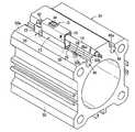
도1 내지 도6에 도시된 바와 같이, 상기 위치검출센서(10)는, 레진 재료로부터 형성된 중공(hollow)의 홀더(12)와, 상기 홀더(12) 속으로 삽입된 센서(14)와 상기 센서(14)의 일단부에 결합된 리드와이어(16)를 포함한다.As shown in Figs. 1 to 6, the
상기 홀더(12)는 바닥이 형성된 관의 형상을 가지고, 단면이 거의 직사각형이며, 상기 센서(14)가 삽입되는 일단부에 배치된 개구부(18)와, 후술(後術)되는 한 고정부(fitting)(20)에 대하여 연결된 타단부에 형성된 커넥터(22)와, 실린더장치(작동기)(24)의 일측부와 결합을 위해 바닥측면(12a)으로부터 돌출한 결합돌기(26)와, 상기 고정부(20)의 핀홀(28)에 결합되는 바닥측면(12a)에 형성된 핀(결합부재)(30)을 포함한다.The
상기 개구부(18)는 대략 직사각형의 단면을 가지고, 상기 센서(14)는 리드와이어(16)와 결합되고 상기 홀더(12) 속으로 상기 개구부(18)를 통해 삽입된다(도 6 참조). 또한, 용융 레진 재료(M)(예를 들어, 열가소성 레진)은 상기 홀더(12) 속에 서 채워지고 경화된다. 결과적으로, 상기 센서(14)는 상기 홀더(12) 속에서 일체로 고정되고 형성된다. 상기 리드와이어(16)는 상기 리드와이어(16)가 상기 홀더(12)의 개구부(18)로부터 외부로 노출되도록 유지된다.The
상기 센서(14)는 상기 실린더장치(24) 내에서 피스톤(31)(도 5 참조)의 위치를 검출할 수 있는 자기센서(검출기)(32)에 형성된 기판(36)과, 상기 피스톤(31)이 상기 자기센서(32)에 의해 검출될 때 빛을 내는 전기발광램프(34)를 포함하며, 상기 리드와이어(16)는 상기 기판(36)에 연결된다. 보다 상세하게는, 상기 피스톤(31)의 외주면에 환상(環狀)홈에 설치된 자석(도 5 참조)(37)으로부터 나온 자기력이 상기 자기센서(32)에 의해 검출되어 상기 피스톤(31)의 위치가 검출되도록 한다.The
상기 커넥터(22)는 상기 홀더(12)의 타단부로부터 돌출되도록 배치되며, 상기 실린더장치(24)의 일측면 위의 상기 커넥터(22)의 바닥면이 상기 홀더(12)의 바닥면에 대해 실질적으로 같은 높이로 형성된다. 또한, 상기 커넥터(22)의 상면이 상기 홀더(12)의 상면보다 낮게 배치된다(도 6 참조). 더욱 상세하게는, 상기 커넥터(22)는 단차부(stepped portion)로 형성된다.The
또한, 상기 홀더(12)의 축에 실질적으로 수직 방향으로 관통하는 볼트홀(38)은 상기 커넥터(22) 내에 형성되며, 상기 홀더(12)와 상기 고정부(20)를 결합하는 연결볼트(연결부재)(40)는 상기 볼트홀(38)을 통해 삽입된다.In addition, a
상기 결합돌기(26)는 상기 홀더(12)의 바닥측면(12a) 위에 대략 중앙 위치에 형성되며, 상기 실린더장치(24)의 일측면을 향하여 상기 바닥측면(12a)으로부터 소 정의 높이(도 8의 H 참조)로 돌출한다. 상기 결합돌기(26)는 상기 홀더(12)의 축방향을 따라 연장되며, 상기 홀더(12)의 길이 치수와 거의 같은 길이 치수를 가진다. 즉, 상기 결합돌기(26)는 상기 홀더(12)의 일단부에서 타단부로 직선으로 연장된다.The
또한, 상기 결합돌기(26)의 바닥면은 상기 홀더(12)를 향해 소정의 곡률반경으로 오목하게 형성되거나 내부로 휘어진 원호형상의 곡면(42)을 포함한다. 뒤에 설명될, 상기 곡면(42)의 곡률반경은 상기 고정부(20)의 곡률반경과 대략 동일하도록 설정되었다.In addition, the bottom surface of the
실린더장치(24)의 일측면을 향해 바닥측면(12a)으로부터 돌출된 핀(30)이 상기 홀더(12)의 일단부에 형성된다. 상기 핀(30)은 소정의 지름을 가지며 축방향으로 형성된다. 즉, 상기 핀(30)은 상기 결합돌기(26)와 같은 방향으로 돌출하며 상기 핀(30)이 상기 홀더(12)의 축에 대략 수직으로 형성되기 때문에, 상기 핀(30)은 상기 커넥터(22)의 상기 볼트홀(38)과 대략 평행하게 소정의 거리만큼 이격되어 있다.A
한편, 표시창(44)은 상기 홀더(12)의 내부로 삽입되는 상기 센서(14)의 전기발광램프(34)에 대면하면서, 상기 홀더(12)의 상면에 배치된다. 상기 표시창(44)은 예를 들어, 투명한 레진 재료로 만들어지며 상기 홀더(12)의 홀부(46) 속에 밀봉설치된다.Meanwhile, the
특히, 상기 홀더(12)의 내부는 상기 표시창(44)을 통해 외부로부터 시각적으로 인식될 수 있기 때문에, 상기 전기발광램프(34)가 발광할 때 상기 홀더(12)의 외부로부터 확인될 수 있다.In particular, since the inside of the
상기 실린더장치(24)에 대하여 상기 홀더(12)를 포함하는 상기 위치검출센서(10)를 고정하기 위한 기둥 형태의 고정부(20)는 상기 홀더(12)의 하부에 배치된다.A pillar-
상기 고정부(20)는 예를 들어, 황동 등과 같은 금속 재료로 축 형식으로 상기 홀더(12)의 축 길이보다 소정의 길이만큼 길게 형성된다. 상기 고정부(20)는 상기 실린더장치(24)의 센서홈(48)을 통해 삽입된다.The
상기 센서홈(48)은 상기 실린더장치(24)를 구성하는 실린더튜브(50)의 외측면(50a)으로 오목한 홈으로 형성되며, 상기 실린더튜브(50)의 일단부에서 타단부로 직선으로 관통한다(도 1 참조).The
또한, 상기 센서홈(48)은 대략 원형의 단면 형태를 가지며, 상기 센서홈(48)과 상기 실린더튜브(50)의 외측면(50a) 사이에 형성된 연통부(48a)를 통해 외부와 전달된다. 상기 연통부(48a)는 상기 센서홈(48)의 원형 영역의 지름보다 작은 소정의 폭을 가진다. 또한, 팽창부(50b)가 상기 연통부(48a)를 마주보는 방향으로 연장되는 상기 실린더튜브(50) 위에 형성된다. 상기 연통부(48a)를 포함하는 이런 요소들은 집합적으로 센서홈(48)으로 기능한다.In addition, the
상기 센서홈(48)의 원형 형태의 영역의 반지름은 상기 고정부(20)의 반지름과 대략 같거나 약간 크다. 이 경우에, 상기 센서홈(48)의 상기 연통부(48a)는 상기 실린더튜브(50)의 외측면을 향해 개방되어, 상기 홀더(12)의 상기 결합돌기(26)가 상기 연통부(48a) 속으로 삽입된다. 상기 센서홈(48) 속의 상기 연통부(48a)의 폭치수는 상기 결합돌기(26)의 폭치수와 대략 같거나 약간 크다.The radius of the circular region of the
상기 고정부(20)는 상기 고정부(20)의 일단부에 형성되어 상기 고정부(20)의 축과 대략 수직 방향으로 관통하는 제1나사홀(52), 상기 홀더(12)의 상기 핀(30)을 통해 삽입되는 상기 제1나사홀(52)로부터 소정 거리 떨어진 핀홀(28)과 상기 고정부(20)의 다른 말단에 형성된 제2나사홀(54)을 포함한다. 상기 고정부(20)의 일단부는 상기 홀더(12)의 커넥터(22)의 일측면을 향해 위치하며, 타단부는 상기 홀더(12)의 상기 개구부(18)와 인접하여 위치한다.The fixing
상기 핀홀(28)은 상기 제1 및 제2 나사홀(52, 54)과 대략 평행하게 형성되고 같은 방향들로 개방되며, 상기 나사홀(52,54)은 상기 핀홀(28)으로부터 상호 소정 거리만큼 떨어져 있다(도 4 및 6 참조). 또한, 상기 고정부(20)의 축 방향을 따라 상기 제1나사홀(52)과 상기 핀홀(28) 사이의 거리는 상기 홀더(12)의 축 방향을 따라 상기 볼트홀(38)과 상기 핀(30) 사이의 거리와 대략 같다.The
상기 제1나사홀(52)은 상기 홀더(12)가 상기 고정부(20)에 고정될 때, 상기 볼트홀(38)을 마주하는 위치에 배치되며, 상기 볼트홀(38)을 통해 관통하는 상기 연결볼트(40)는 그 사이에서 나사결합된다. 결과적으로, 상기 홀더(12)를 포함하는 상기 위치검출센서(10)는 상기 고정부(20)와 결합한다. 이때, 상기 홀더(12)의 상기 핀(30)은 상기 핀홀(28) 속으로 삽입되어서, 결과적으로 상기 홀더(12)는 상기 연결볼트(40)와 상기 핀(30)을 통해 상기 고정부(20)에 위치결정되어 고정된다.The
더욱 상세하게는, 상기 고정부(20)는 그 안에 형성된 상기 제2나사홀(54)을 가지는 타단부가 홀더(12)의 단부로부터 고정된 거리만큼 돌출하도록 부착된다(도 2 참조).More specifically, the fixing
상기 센서홈(48)에 대하여 상기 고정부(20)를 고정하는 고정나사(고정부재)(56)가 상기 제2나사홀(54)에 결합되어 상기 고정나사(56)의 나사 회전 작동하에 제2나사홀(54)을 따라 축 방향으로 변위 가능하다. 또한, 상기 센서홈(48)의 바닥부(48b) 쪽으로 상기 고정나사(56)의 변위와 돌출의 결과, 상기 고정부(20)는 상기 바닥부(48b)로부터 멀리 떨어지기 위해, 일방향으로(상기 연통부(48a)의 측부를 향해) 상기 고정나사(56)에 의해 상향으로 밀어진다. 그리하여, 상기 고정부(20)는 상기 센서홈(48)의 내벽면에 맞닿은 상태에서 압박된다. 그로 인해, 상기 고정부(20)의 동작은 상기 센서홈(48)을 가진 상기 고정부(20)의 접촉 동작하에서 조절 및 고정된다.A fixing screw (fixing member) 56 for fixing the fixing
또한, 전술한 상기 고정부(20)는 상기 고정부(20)가 원형의 단면을 가지는 중공이 아닌 축으로 형성되는 경우에 대하여 설명되었지만, 본 발명은 이 특징에 의해 한정되지 않는다. 예를 들어, 상기 고정부(20)는 유사한 사변형(quadrilateral)의 단면 형태를 가지는 센서홈(48)에 상응하는 사변형의 단면을 가질 수도 있다. 더우기, 상기 고정부(20)는 중공의 원통 형태로 형성될 수 있다. 특히, 상기 홀더(12)를 포함하는 상기 위치검출센서(10)가 상기 실린더장치(24)에 연결고정될 때, 상기 고정부(20)가 충분한 강도를 가지는 한, 상기 고정부(20)의 형태는 특별히 제한되지 않는다.In addition, the above-described fixing
본 발명의 실시예에 따른 상기 위치검출센서(10)는 위에서 설명된 바와 같이, 기본적으로 구성되었다. 그리고, 상기 위치검출센서(10)가 상기 고정부(20)를 통해서 상기 실린더장치(24)에 맞추어지는 경우가 설명될 것이다.The
첫째, 상기 고정부(20)는 상기 위치검출센서(10)를 구성하는 상기 홀더(12)에 대하여 연결된다. 이 경우, 도 4에 도시된 바와 같이, 상기 고정부(20)는 상기 홀더(12)의 바닥측면(12a) 상에 정렬되며, 상기 홀더(12)의 핀(30)은 상기 핀홀(28) 속으로 삽입된다(도 8 참조). 이와 함께, 상기 볼트홀(38)로 삽입된 상기 연결볼트(40)는 상기 고정부(20)의 상기 제1나사홀(52)로 결합된다. 이때, 상기 홀더(12)와 상기 고정부(20)는 평행으로 배치되며, 상기 핀(30)은 상기 핀홀(28) 속으로 삽입되어, 상기 홀더(12)는 상기 고정부(20)에 대하여 위치결정된다. 또한, 상기 제1나사홀(52)이 상기 홀더(12)의 상기 볼트홀(38)과 일치하도록 하여 상기 고정부(20)를 상기 핀(30)의 중심에 대하여 회전하는 것에 의해, 상기 제1나사홀(52)이 상기 볼트홀(38)에 마주보도록 배치될 수 있다. 이런 식으로, 먼저 상기 핀홀(28) 내에 상기 핀(30)을 결합하여, 상기 볼트홀(38)과 제1나사홀(52)이 같은 선 위에서 일치하도록 쉽게 배치될 수 있다.First, the fixing
추가적으로, 상기 제1나사홀(52)에 대하여 상기 볼트홀(38)을 통해 삽입된 상기 연결볼트(40)의 나사결합에 의해, 상기 홀더(12)를 포함한 상기 위치검출센서(10)는 상기 연결볼트(40)에 의하여 상기 고정부(20)와 일체로 연결된다.(도 2 참조). 상기 홀더(12)의 일단부가 상기 핀(30)을 통하여 상기 고정부(20) 상에 유지되는 반면에, 타단부는 상기 연결볼트(40)에 의해 상기 고정부(20) 상에 유지되기 때문에, 상기 홀더(12)는 상기 고정부(20)와 더욱 확고하게 연결되고 일체가 될 수 있다.In addition, the
더우기, 상기 홀더(12)와 상기 고정부(20)는 소정 거리의 간극이 상기 홀더(12)의 결합돌기(26)와 상기 고정부(20) 사이에 확보되는 상태에서 서로 결합된다.In addition, the
다음으로, 상기 고정부(20)에 결합된 위치검출센서(10)는 상기 실린더장치(24)에 조합된다. 이 경우에, 상기 고정부(20)는 상기 실린더장치(24)의 상기 센서홈(48)의 개방된 단부로 삽입된다. 상기 고정부(20)는 상기 센서홈(48)을 통하여 삽입되어서, 상기 위치검출센서(10)가 상기 센서홈(48)의 상기 연통부(48a)를 통하여 상기 실린더튜브(50)의 외측면(50a)에 대하여 외부에 배치된다.Next, the
게다가, 상기 위치검출센서(10)는 상기 고정부(20)와 함께 상기 센서홈(48)을 따라 이동하고, 상기 위치검출센서(10)에 의한 상기 피스톤(31)의 위치의 검출이 가능한 바람직한 위치로의 이동 이후에 상기 위치검출센서(10)는 원하는 위치에 고정된다.In addition, the
이러한 방법으로 상기 위치검출센서(10)를 고정할 때, 상기 홀더(12)를 관통하는 상기 연결볼트(40)를 회전시킴으로써, 상기 홀더(12)의 상기 커넥터(22)와 상기 고정부(20)는 서로 접근하는 방향으로 당겨진다. 또한, 상기 홀더(12)의 바닥측면(12a)이 상기 실린더튜브(50)의 외측면(50a)에 맞닿은 상태에서 압박되고, 상기 고정부(20)의 외주면이 상기 센서홈(48)의 내벽면에 맞닿아 압박된다(도 7 참조). 결과적으로, 상기 센서홈(48)의 상기 연통부(48a)는 잡히고 상기 실린더튜브(50)의 팽창부(50b)가 상기 홀더(12)와 상기 고정부(20)에 의해 조여지는 상태에 위치한다.When fixing the
달리 말하면, 상기 홀더(12)의 바닥측면(12a)이 주어진 압박력(P1)과 상기 실린더튜브(50)의 외측면(50a)에 대한 상기 연결볼트(40)의 죄는 힘으로 압박된다. 다른 한편, 상기 고정부(20)의 외주면이 상기 센서홈(48)의 내벽면에 대하여 주어진 압박력(P2)으로 압박된다(도 7 참조).In other words, the
결과적으로, 상기 위치검출센서(10)는 상기 센서홈(48)에 대하여 원하는 위치에서 상기 홀더(12)와 상기 고정부(20)에 의해 고정된다. 이 경우에, 도 8에 도시된 바와 같이, 상기 홀더(12)의 상기 결합돌기(26)와 상기 고정부(20)의 외주면이 소정의 거리만큼 떨어지도록 설정된다.As a result, the
결국, 상기 고정부(20)의 상기 제2나사홀(54) 내에 나사결합된 상기 고정나사(56)가 회전되고, 상기 고정나사(56)는 상기 센서홈(48)의 상기 바닥(48b)을 향해 돌출하면서 변위되어서, 상기 고정부(20)가 상기 센서홈(48)의 상기 연통부(48a)의 측부를 향해 상방으로 압박된다. 결과적으로, 상기 고정부(20)의 외주면이 상기 센서홈(48)의 내벽면을 향하여 압박되고 그 사이의 접촉 작용 하에서 고정된다(도 9 참조). 더욱 자세하게는, 상기 위치검출센서(10)는 상기 홀더(12)와 상기 고정부(20) 사이의 실린더튜브(50)의 팽창부(50b)을 쥠으로써 상기 실린더장치(24)에 대하여 고정되며, 게다가 상기 고정부(20)가 상기 센서홈(48)에 대하여 상기 고정나사(56)를 통해서 고정되기 때문에, 상기 위치검출센서(10)는 확고하고 안전하게 고정된다.As a result, the fixing
전술한 방법으로, 발명의 실시예에서, 상기 위치검출센서(10)가 상기 실린더장치(24)에 고정될 때, 그리고 상기 고정부(20)가 상기 위치검출센서(10)의 바닥측 면(12a)에 미리 설치된 후에, 상기 고정부(20)가 상기 실린더장치(24)의 상기 센서홈(48)을 통하여 삽입된다. 또한, 상기 연결볼트(40)의 나사작용 하에, 상기 위치검출센서(10)를 구성하는 상기 홀더(12)와 상기 고정부(20)가 서로 접근하도록 변위되고, 그 사이에 상기 실린더장치(24) 속의 상기 센서홈(48)의 팽창부(50b)을 조임으로써 고정된다.By the above-described method, in the embodiment of the invention, when the
이런 방법으로, 위치 결정이 상기 센서(14)가 수용된 상기 홀더(12)의 바닥측면(12a)의 접합부를 통하여 수행되기 때문에, 상기 실린더튜브(50)의 외측면(50a)에 대하여 상기 위치검출센서(10)가 고정될 때, 상기 홀더(12)와 상기 실린더튜브(50) 사이의 상호 위치 관계의 변화는 일어나지 않는다. 특히, 고정된 거리는 상기 홀더(12) 내의 상기 자기센서(32)와 상기 실린더튜브(50) 내에 형성된 상기 피스톤(31) 사이에서 유지되어서, 상기 자기센서(32)에 의한 안정적인 검출 결과가 얻어질 수 있다. 달리 말하면, 종래의 위치 검출 센서에 사용되고 상기 위치거출센서가 상기 설치홈 내에 부착될 때 상기 위치검출센서와 상기 피스톤의 상대적인 위치의 변화가 발생하는 경향이 있는 고정부 구조와 비교해 볼 때, 본 발명의 상기 위치검출센서(10)에 의하여 검출 정확도는 개선될 수 있다.In this way, since the positioning is performed via the junction of the
게다가, 상기 고정부(20)가 상기 센서홈(48)에 관하여 상기 제2나사홀(54) 내에 나사결합되는 상기 고정나사(56)에 의하여 고정될 수 있기 때문에, 상기 연결볼트(40)는 나사 회전될 수 있으며, 상기 홀더(12)를 포함하는 상기 위치검출센서(10)는 상기 고정부(20)가 상기 센서홈(48) 내에 설치되어 있는 상태에서 상기 고정부(20)으로부터 이탈될 수 있다.In addition, since the fixing
결과적으로, 상기 위치검출센서(10)를 교환하거나 교체하는 것을 포함한 유지 동작이 쉽게 수행될 수 있으며, 다른 사항을 가지는 다른 위치 검출 센서를 상기 고정부(20)에 새로이 결합할 수 있으며 그것을 이용할 수 있다.As a result, a maintenance operation including exchanging or replacing the
예를 들어, 상기 위치 검출 센서가 미리 고정되었던 고정부(20)에 결합된다는 사실 때문에 다른 위치 검출 센서가 상기 실린더장치(24)에 설치되는 경우에, 상기 피스톤(31)의 위치를 검출할 수 있는 그 위치에의 설치는 쉽고 빠르게 이루어질 수 있다. 즉, 상기 실린더장치(24) 상에서 상기 위치검출센서(10)의 상기 피스톤의 재조정의 어렵고 복잡한 작업이 불필요하고, 상기 실린더장치(24) 상에서 상기 위치검출센서(10)의 설치 위치의 재현이 개선될 수 있다.For example, when another position detection sensor is installed in the
또한, 상기 고정부(20)가 금속 재료로 만들어졌기 때문에, 상기 위치검출센서(10)가 상기 센서홈(48)에 고정될 때, 상기 고정부(20)가 상기 센서홈(48)의 내벽면에 압박될 때에도, 상기 고정부(20)는 변형되지 않고 상기 고정부(20)의 내구성은 감소하지 않는다. 또한, 상기 고정부(20)가 레진 재료로 만들어지는 경우와 비교할 때, 상기 고정부(20)의 강도가 증가되기 때문에, 상기 연결볼트(40)가 상기 고정부(20)가 나사 결합되는 결속력(결속토크)은 더 큰 값을 가질 수 있다. 결과적으로, 상기 위치검출센서(10)는 상기 연결볼트(40)에 의해 상기 실린더장치(24)에 대하여 확고하고 안정되게 고정될 수 있다.In addition, since the fixing
앞에서 언급한 본 발명에 따른 위치검출센서(10)에서, 상기 결합돌기(26)의 하단면이 아치형으로 내부로 굽어지도록 형성되는 것으로 설명되었지만, 본 발명은 이런 특징에 제한되는 것은 아니다. 상기 결합돌기(26)의 하단면은 평평하거나 평 면의 표면을 가지도록 형성될 수도 있다.In the above-described
게다가, 도 2와 3에 도시된 바와 같이, 상기 고정부(20)가 상기 홀더(12)의 상기 개구부(18)의 측부에 상기 홀더(12)로부터 주어진 길이만큼 돌출하도록 구성되었다. 그러나, 상기 고정부(20)는 예를 들어 반대 방식, 상기 홀더(12)의 상기 커넥터(22)의 측부으로부터 돌출될 수도 있다. 게다가, 상기 고정부(20)가 상기 홀더(12)의 양단으로부터 상대적으로 돌출되는 것도 인정될 수 있다.In addition, as shown in FIGS. 2 and 3, the fixing
다음으로, 도 10에서 22를 참조하여, 앞에서 설명한 위치검출센서(10)의 변형예가 설명될 것이다.Next, a modification of the
도 10과 11에 도시된 바와 같이, 제1변형예에 따른 상기 위치검출센서(100)는 앞에서 언급한 실시예의 상기 고정부(20)와는 상기 위치검출센서(100)를 구성하는 고정부(102)가 상기 홀더(12)의 수직 치수와 대략 같은 길이로 형성된다는 면에서 다르다. 상기 연결볼트(40)가 나사 결합된 상기 제1나사홀(52)은 상기 고정부(102)의 일단부에 형성되었으며 상기 홀더(12)의 상기 핀(30)이 삽입된 상기 핀홀(28)은 상기 고정부(102)의 타단부에 형성된다. 즉, 상기 고정부(102)는 또한 상기 고정나사(56)의 나사결합용 제2나사홀(54)을 가지고 있지 않다는 점에서 앞에서 언급한 실시예의 고정부(20)와 다르다.10 and 11, the
이런 식으로, 단 하나의 제1나사홀(52)과 상기 핀홀(28)만을 가지는 상기 고정부(102)의 사용을 적용함으로써, 앞에서 언급한 고정부(20)와 비교했을 때, 상기 고정부(102)는 크기가 더 작도록 만들어질 수 있는 반면에 상기 고정부(102)의 구조는 단순화되고 더 낮은 비용으로 제조될 수 있다.In this way, by applying the use of the fixing
또한, 도 12와 13에 도시된 바와 같이, 제2변형예에 따른 상기 위치검출센서(120)에서, 상기 고정부(122)는 전술한 제1변형예에 따른 상기 위치검출센서(100)의 상기 고정부(102)와 비교했을 때 더욱 작게 만들어질 수 있다. 상기 연결볼트(40)가 나사결합되는 상기 제1나사홀(52)은 상기 축 방향을 따라 실질적으로 상기 고정부(122) 중심에 형성된다. 즉, 상기 고정부(122)는 상기 고정나사(56)의 나사 결합용인 상기 제2나사홀(54), 또는 상기 홀더(12)의 상기 핀(30)이 삽입되는 상기 핀홀(28)을 가지지 않는다는 점에서 앞에서 언급한 실시예의 상기 고정부(20)와 다르다. 상기 고정부(122)는 또한 상기 핀홀(28)을 가지지 않는다는 점에서 제1변형예에 따른 앞에서 언급한 고정부(102)와 다르다.12 and 13, in the
이런 식으로, 제1나사홀(52)만을 가지는 상기 고정부(122)의 사용을 적용함으로써, 상기 고정부(122)는 크기가 더 작아질 수 있고, 동시에 상기 고정부(122)의 구조는 단순화되고 적은 비용으로 제조될 수 있다.In this way, by applying the use of the fixing
게다가, 도 14에서 16에 도시된 바와 같이, 제3변형예에 따른 상기 위치검출센서(130)에서, 그 속의 상기 고정부(132)는 앞에서 언급한 제1변형예의 상기 고정부(102)의 길이 치수와 대략 같은 길이 치수로 형성되며, 상기 고정부(132)는 상기 홀더(134)에 대하여 상기 볼트홀(38)의 측부로(화살표 A의 방향으로) 오프셋되면서 설치된다. 상기 고정부(132)는 상기 연결볼트(40)가 결합된 축방향을 따라 대략 상기 고정부(132)의 중심에 형성된 제1나사홀(52)과, 상기 고정나사(56)가 일단부에(화살표 A의 방향으로) 결합된 상기 제2나사홀(54)과, 상기 홀더(134)의 상기 핀(30)이 삽입되는 타단부에(화살표 B의 방향으로) 형성된 상기 핀홀(28)을 가진 다.In addition, as shown in FIGS. 14 to 16, in the
특히, 상기 제1나사홀(52), 상기 제2나사홀(54)과 상기 핀홀(28)은 상기 축 방향을 따라 소정의 거리를 두고 상기 고정부(132) 내에 배치된다.In particular, the
게다가, 상기 홀더(134)의 상기 핀(30)은 상기 홀더(134)의 축 방향을 따라 대략 중심적에 형성된다.In addition, the
이런 식으로, 제3변형예에 따른 상기 위치검출센서(130)에서, 상기 고정나사(56)가 결합되는 제2나사홀(54)이 상기 고정부(132)의 일단부에(화살표 A의 방향으로) 형성되기 때문에, 상기 고정부(132)는 상기 홀더(134)의 일단부로부터 돌출되도록 배치되어서, 상기 고정나사(56)가 회전하여 결합할 때, 상기 홀더(134)의 타단부로부터 돌출한 상기 리드와이어(16)는 상기 위치검출센서(130)의 고정 동작을 방해하지 않으며, 상기 고정부(132)를 통한 상기 위치검출센서(130)의 고정은 안전하고 효율적으로 수행될 수 있다.In this way, in the
또한, 상기 고정부(132)의 길이 치수가 앞에서 언급한 본 발명의 실시예에 따른 상기 위치검출센서(10)의 상기 고정부(20)보다 짧기 때문에, 상기 고정부(132)가 상기 센서홈(48) 내에 고정될 때, 상기 고정부(132)의 외주면과 상기 센서홈(48)의 내주면 사이의 접촉면적은 줄어들게 된다. 이로 인하여, 상기 고정부(132)가 상기 고정나사(56)의 나사회전을 통하여 상기 센서홈(48)의 상기 내주면을 향하여 변위될 때, 상기 고정부(132)로부터 상기 센서홈(48)을 향해 가해진 단위 면적당 압박 하중은 더 커지게 될 수 있으며, 결과적으로 상기 위치검출센서(130)는 상기 센서홈(48)에 대하여 확고하게 고정될 수 있다.In addition, since the length dimension of the fixing
또한, 도 17 내지 19에 도시된 바와 같이, 제4변형예에 따른 상기 위치검출센서(140)에서, 상기 고정부(142)는 그 길이 치수가 발명의 실시예에 따른 상기 위치검출센서(10)의 상기 고정부(20)의 길이 치수와 실제적으로 동일하도록 형성되지만, 상기 고정부(142)는 그 내부에 상기 볼트홀(38)을 가지는 상기 홀더(12)의 일단부로부터(화살표 A의 방향으로) 돌출되도록 형성된다는 점에서 앞에서 언급한 발명의 실시예에 따른 상기 위치검출센서(10)와 다르다.17 to 19, in the
상기 고정부(142)의 일단부(화살표 A의 방향으로)는 상기 홀더(12)의 단부로부터 소정 길이로 돌출하도록 형성되고, 상기 홀더(12)의 단부를 마주보는 위치에 상기 연결볼트(40)가 결합되는 제1나사홀(52)을 가지도록 형성된다. 또한, 상기 고정나사(56)가 결합되는 제2나사홀(54)은 상기 고정부(142)의 일단부에 형성되는 반면에, 상기 홀더(12)의 상기 핀(30)이 삽입되는 핀홀(28)은 상기 고정부(142)의 타단부에 형성된다.One end of the fixing part 142 (in the direction of arrow A) is formed to protrude from the end of the
이런 식으로, 제4변형예에 따른 상기 위치검출센서(140)에서, 상기 고정나사(56)가 결합되는 제2나사홀(54)이 상기 고정부(142)의 일단부에(화살표 A의 방향으로) 형성되기 때문에, 상기 고정부(142)는 상기 홀더(12)의 일단부로부터 돌출되도록 형성되어, 상기 고정나사(56)가 회전하여 결합할 때, 상기 홀더(12)의 타단부로부터 돌출한 상기 리드와이어(16)는 상기 위치검출센서(140)의 고정 동작을 방해하지 않으며, 상기 고정부(142)를 통한 상기 위치검출센서(140)의 고정은 안전하고 효율적으로 수행될 수 있다.In this way, in the
또한, 도 20 내지 22에 도시된 바와 같이, 제5변형예에 따른 상기 위치검출 센서(150)는 상기 고정부(152)가 상기 위치검출센서(150)를 구성하는 상기 홀더(12)의 양단부로부터 각각 돌출하도록 형성된다는 점에서 전술한 발명의 실시예에 따른 상기 위치검출센서(10)와 다르다.In addition, as shown in FIGS. 20 to 22, the
상기 고정부(152)가 상기 홀더(12)의 치수 길이보다 긴 치수 길이를 가지도록 형성되어, 상기 고정부(152)가 상기 홀더(12)에 대하여 설치될 때, 상기 고정부(152)의 양단부가 상기 홀더(12)의 각 단부로부터 각각 소정 길이로 돌출한다.The fixing
상기 홀더(12)의 상기 볼트홀(38)을 마주보는 상기 제1나사홀(52)이 상기 고정부(152)의 일단부에(화살표 A 방향으로) 형성되는 반면에, 상기 홀더(12)의 상기 핀(30)이 삽입되는 상기 핀홀(28)이 상기 고정부(152)의 타단부에(화살표 B 방향으로) 형성된다.While the
게다가, 고정나사(56a, 56b)가 결합되는 한 쌍의 제2나사홀(154a, 154b)이 상기 고정부(152)의 각 단부 상에 형성된다.In addition, a pair of
이런 식으로, 제5변형예에 따른 상기 위치검출센서(150)에서, 한 쌍의 상기 고정나사(56a, 56b)가 상기 고정부(152)의 양단부 상의 상기 제2나사홀(154a, 154b)을 통하여 배치되서, 상기 고정부(152)는 상기 고정나사(56a, 56b)에 의하여 상기 센서홈(48) 내에 고정될 수 있다. 이로 인해, 상기 고정부(152)를 포함하는 상기 위치검출센서(150)는 더욱 안전하고 효율적으로 제자리에 고정될 수 있다. 또한, 상기 한 쌍의 고정나사(56a, 56b) 중 하나가 선택되서, 상기 센서홈(48)에 대하여 고정 위치에 대응하도록 상기 위치검출센서(150)를 고정하는 데 사용될 수 있다.In this way, in the
발명이 특히 바람직한 실시예를 참조하여 도시되고 설명되었지만, 첨부된 청구항에 의해 정의된 바와 같은 본 발명의 정신과 범위에서 벗어나지 않고서 변화와 변경이 당해기술의 전문가에 의해서 이루어질 수 있다는 것이 이해될 것이다.While the invention has been shown and described with reference to particularly preferred embodiments, it will be understood that changes and modifications may be made by those skilled in the art without departing from the spirit and scope of the invention as defined by the appended claims.
도 1은 본 발명의 일실시예에 따른 위치 검출 센서가 고정부(fitting)에 의해 고정된 시린더 장치를 도시한 외부 사시도이다.1 is an external perspective view illustrating a cylinder device in which a position detection sensor is fixed by a fitting. Referring to FIG.
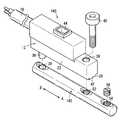
도 2는 도 1에 도시된 위치 검출 센서와 고정부가 결합된 상태를 도시한 외부 사시도이다.FIG. 2 is an external perspective view illustrating a state in which the position detection sensor and the fixing unit illustrated in FIG. 1 are coupled to each other.
도 3은 도 2에 도시된 위치 검출 센서와 고정부의 평면도이다.3 is a plan view of the position detection sensor and the fixing unit shown in FIG. 2.
도 4는 고정부가 도 2에 도시된 위치 검출 센서로부터 분리된 상태를 도시한 분해 사시도이다.4 is an exploded perspective view illustrating a state in which the fixing part is separated from the position detection sensor shown in FIG. 2.
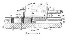
도 5는 고정부를 통하여 고정된 도 1의 위치 검출 센서를 가지는 실린더 장치를 도시한 수직 단면도이다.FIG. 5 is a vertical sectional view of the cylinder device having the position detection sensor of FIG. 1 fixed through the fixing portion. FIG.
도 6은 도 1에 도시된 위치 검출 센서가 고정부를 통하여 실린더 장치에 고정된 상태를 도시한 수직 단면도이다.6 is a vertical cross-sectional view showing a state in which the position detection sensor shown in FIG. 1 is fixed to a cylinder device through a fixing unit.
도 7은 도 6의 선 VII-VII을 따라 절단된 단면도이다.FIG. 7 is a cross-sectional view taken along the line VII-VII of FIG. 6.
도 8은 도 6의 선 VIII-VIII을 따라 절단된 단면도이다.8 is a cross-sectional view taken along the line VIII-VIII of FIG. 6.
도 9는 도 6의 선 IX-IX를 따라 절단된 단면도이다.FIG. 9 is a cross-sectional view taken along the line IX-IX of FIG. 6.
도 10은 제1변형예에 따른 위치 검출 센서의 고정부가 상기 홀더로부터 분리된 상태를 도시하는 분해 사시도이다.10 is an exploded perspective view showing a state where the fixing part of the position detection sensor according to the first modification is separated from the holder.
도 11은 도 10에 도시된 위치 검출 센서가 실린더 장치에 대하여 고정된 상태를 도시하는 수직 투시도이다.FIG. 11 is a vertical perspective view showing a state where the position detection sensor shown in FIG. 10 is fixed with respect to the cylinder device.
도 12는 제2변형예에 따른 위치 검출 센서의 고정부가 상기 홀더로부터 분리 된 상태를 도시하는 분해 사시도이다.12 is an exploded perspective view showing a state where the fixing part of the position detection sensor according to the second modification is separated from the holder.
도 13은 도 12에 도시된 위치 검출 센서가 실린더 장치에 대하여 고정된 상태를 도시하는 수직 투시도이다.FIG. 13 is a vertical perspective view showing a state where the position detection sensor shown in FIG. 12 is fixed with respect to the cylinder device.
도 14는 제3변형예에 따른 위치 검출 센서를 도시한 외부 사시도이다.14 is an external perspective view showing a position detection sensor according to a third modification.
도 15는 도 14의 위치 검출 센서를 구성하는 고정부가 상기 홀더로부터 분리된 상태를 도시한 분해 사시도이다.FIG. 15 is an exploded perspective view illustrating a state in which a fixing part constituting the position detection sensor of FIG. 14 is separated from the holder.
도 16은 도 14에 도시된 위치 검출 센서가 실린더 장치에 대하여 고정된 상태를 도시하는 수직 투시도이다.FIG. 16 is a vertical perspective view showing a state where the position detection sensor shown in FIG. 14 is fixed with respect to the cylinder device.
도 17은 제4변형예에 따른 위치 검출 센서를 도시하는 외부 사시도이다.17 is an external perspective view showing a position detection sensor according to a fourth modification.
도 18은 도 17의 위치 검출 센서를 구성하는 고정부가 상기 홀더로부터 분리된 상태를 도시한 분해 사시도이다.FIG. 18 is an exploded perspective view illustrating a state in which a fixing part constituting the position detection sensor of FIG. 17 is separated from the holder.
도 19은 도 17에 도시된 위치 검출 센서가 실린더 장치에 대하여 고정된 상태를 도시하는 수직 투시도이다.19 is a vertical perspective view showing a state where the position detection sensor shown in FIG. 17 is fixed with respect to the cylinder device.
도 20은 제5변형예에 따른 위치 검출 센서를 도시하는 외부 사시도이다.20 is an external perspective view illustrating a position detection sensor according to a fifth modification.
도 21은 도 20의 위치 검출 센서를 구성하는 고정부가 상기 홀더로부터 분리된 상태를 도시한 확대 사시도이다.FIG. 21 is an enlarged perspective view illustrating a state in which a fixing part constituting the position detection sensor of FIG. 20 is separated from the holder.
도 22는 도 20에 도시된 위치 검출 센서가 실린더 장치에 대하여 고정된 상태를 도시하는 수직 투시도이다.FIG. 22 is a vertical perspective view showing a state where the position detection sensor shown in FIG. 20 is fixed with respect to the cylinder device.
Claims (11)
Translated fromKoreanApplications Claiming Priority (4)
| Application Number | Priority Date | Filing Date | Title |
|---|---|---|---|
| JP2006205840 | 2006-07-28 | ||
| JPJP-P-2006-00205840 | 2006-07-28 | ||
| JPJP-P-2007-00161285 | 2007-06-19 | ||
| JP2007161285AJP4374584B2 (en) | 2006-07-28 | 2007-06-19 | Position detection sensor |
Publications (1)
| Publication Number | Publication Date |
|---|---|
| KR20080011119Atrue KR20080011119A (en) | 2008-01-31 |
Family
ID=38859647
Family Applications (1)
| Application Number | Title | Priority Date | Filing Date |
|---|---|---|---|
| KR1020070075729ACeasedKR20080011119A (en) | 2006-07-28 | 2007-07-27 | Position detection sensor |
Country Status (5)
| Country | Link |
|---|---|
| US (1) | US7830137B2 (en) |
| JP (1) | JP4374584B2 (en) |
| KR (1) | KR20080011119A (en) |
| DE (1) | DE102007034900B4 (en) |
| TW (1) | TWI328086B (en) |
Families Citing this family (18)
| Publication number | Priority date | Publication date | Assignee | Title |
|---|---|---|---|---|
| EP2316505B1 (en) | 2006-03-14 | 2017-01-18 | University Of Southern California | Mems device for delivery of therapeutic agents |
| JP2009030674A (en)* | 2007-07-25 | 2009-02-12 | Smc Corp | Position detection sensor mounting mechanism |
| WO2009086112A2 (en) | 2007-12-20 | 2009-07-09 | University Of Southern California | Apparatus and methods for delivering therapeutic agents |
| DE102009013393A1 (en) | 2008-03-27 | 2009-10-01 | Luk Lamellen Und Kupplungsbau Beteiligungs Kg | Connection between sensor housing and component, particularly in form of master cylinder, has sensor housing and component, which have forming elements interlocked into each other in corresponding manner |
| US8486278B2 (en) | 2008-05-08 | 2013-07-16 | Minipumps, Llc | Drug-delivery pumps and methods of manufacture |
| US9849238B2 (en) | 2008-05-08 | 2017-12-26 | Minipumps, Llc | Drug-delivery pump with intelligent control |
| JP5719767B2 (en) | 2008-05-08 | 2015-05-20 | ミニパンプス, エルエルシー | Implantable pump and cannula therefor |
| DE112010000328A5 (en) | 2009-02-12 | 2012-04-05 | Schaeffler Technologies Gmbh & Co. Kg | Hydraulic clutch or brake confirmation system |
| JP2011027614A (en)* | 2009-07-28 | 2011-02-10 | Daishin Seiki Kk | Magnetometric sensor |
| KR101697388B1 (en) | 2009-08-18 | 2017-01-17 | 미니펌프스, 엘엘씨 | Electrolytic drug-delivery pump with adaptive control |
| CN103108665A (en)* | 2010-04-20 | 2013-05-15 | 迷你泵有限责任公司 | Electrolytically driven drug pump devices |
| JP6421444B2 (en)* | 2014-04-30 | 2018-11-14 | Smc株式会社 | Position detection sensor |
| DE102014115224B3 (en)* | 2014-10-20 | 2015-12-31 | Sick Ag | Device and method for mounting a sensor |
| EP3070438B1 (en)* | 2015-03-19 | 2017-02-01 | Sick Ag | Sensor casing |
| JP6614490B2 (en)* | 2015-12-01 | 2019-12-04 | Smc株式会社 | Position detection sensor |
| JP6614489B2 (en) | 2015-12-01 | 2019-12-04 | Smc株式会社 | Position detection sensor |
| JP6398123B2 (en)* | 2016-05-31 | 2018-10-03 | 本田技研工業株式会社 | Sensor unit, device with sensor unit, and method of assembling sensor unit |
| CN115290929B (en)* | 2022-07-28 | 2024-08-27 | 东风电驱动系统有限公司 | Vehicle speed sensor detection device |
Family Cites Families (18)
| Publication number | Priority date | Publication date | Assignee | Title |
|---|---|---|---|---|
| US725753A (en)* | 1902-11-10 | 1903-04-21 | John F Morton | Construction of bridges. |
| FR2425567A1 (en)* | 1978-05-12 | 1979-12-07 | Outillage Air Comprime | CYLINDER |
| DE3900105A1 (en)* | 1988-02-08 | 1989-08-17 | Hans Jochen Eisenberg | Grooved block for an associated C-profile rail |
| JPH037507A (en) | 1989-06-05 | 1991-01-14 | Iseki & Co Ltd | Combine cabin mounting structure |
| JPH0346005A (en) | 1989-07-14 | 1991-02-27 | Mitsubishi Electric Corp | Programmable controller |
| JPH0463803A (en) | 1990-07-04 | 1992-02-28 | Tosoh Corp | Manufacturing method of vinyl chloride resin |
| DE4023792C2 (en) | 1990-07-26 | 2000-05-11 | Siemens Ag | Method of manufacturing a proximity switch with a mounting sleeve |
| JPH0589910A (en) | 1991-09-27 | 1993-04-09 | Yuasa Corp | Manufacture of closed type secondary cell |
| JPH0719603A (en) | 1993-06-30 | 1995-01-20 | Sanyo Electric Co Ltd | Gas fan heater equipped with floor heating function |
| JP3389350B2 (en) | 1994-08-31 | 2003-03-24 | エスエムシー株式会社 | Rod switch mounting mechanism for hydraulic equipment |
| JP3833380B2 (en) | 1997-12-26 | 2006-10-11 | Smc株式会社 | Cylinder with sensor mounting mechanism |
| DE29904367U1 (en)* | 1999-03-10 | 1999-05-27 | Festo AG & Co, 73734 Esslingen | Device for fastening a sensor |
| JP2001263311A (en) | 2000-03-21 | 2001-09-26 | Howa Mach Ltd | Sensor mounting structure for fluid pressure cylinder |
| DE10038001B4 (en)* | 2000-08-04 | 2008-09-18 | Balluff Gmbh | sensor arrangement |
| JP3785538B2 (en) | 2002-10-30 | 2006-06-14 | 太陽鉄工株式会社 | Sensor mounting structure and mounting method in cylinder |
| JP2005009606A (en) | 2003-06-19 | 2005-01-13 | Ckd Corp | Mounting structure for fixtures and incidental members |
| JP2005163941A (en) | 2003-12-03 | 2005-06-23 | Kuroda Pneumatics Ltd | Mounting structure of cylinder switch |
| JP4099779B2 (en)* | 2004-08-09 | 2008-06-11 | Smc株式会社 | Sensor mounting mechanism in fluid pressure cylinder |
- 2007
- 2007-06-19JPJP2007161285Apatent/JP4374584B2/enactiveActive
- 2007-07-24TWTW096126877Apatent/TWI328086B/enactive
- 2007-07-24USUS11/781,952patent/US7830137B2/enactiveActive
- 2007-07-24DEDE102007034900Apatent/DE102007034900B4/enactiveActive
- 2007-07-27KRKR1020070075729Apatent/KR20080011119A/ennot_activeCeased
Also Published As
| Publication number | Publication date |
|---|---|
| DE102007034900A1 (en) | 2008-01-31 |
| TWI328086B (en) | 2010-08-01 |
| US20080022789A1 (en) | 2008-01-31 |
| JP2008051800A (en) | 2008-03-06 |
| US7830137B2 (en) | 2010-11-09 |
| DE102007034900B4 (en) | 2011-02-10 |
| TW200809094A (en) | 2008-02-16 |
| JP4374584B2 (en) | 2009-12-02 |
Similar Documents
| Publication | Publication Date | Title |
|---|---|---|
| KR20080011119A (en) | Position detection sensor | |
| JP4099779B2 (en) | Sensor mounting mechanism in fluid pressure cylinder | |
| KR101009291B1 (en) | Position detection sensor installation mechanism | |
| TWI425151B (en) | Proximate sensor, mounting construction of a proximate sensor, and method for making a proximate sensor | |
| US10145749B2 (en) | Physical quantity measuring device including a sensor module and a joint for locking the sensor module | |
| JP4780682B2 (en) | Cylinder stroke position measuring device | |
| US9952114B2 (en) | Physical quantity measuring device and method of manufacturing the same | |
| KR20140034941A (en) | Clamping device | |
| CN101113910A (en) | position detection sensor | |
| JP2022532053A (en) | Drum brake with load measuring device | |
| US9429587B2 (en) | Sensor with laser welded cover | |
| US5959271A (en) | Stopping device with a switch | |
| JP6654062B2 (en) | Stroke sensor | |
| JPH1151011A (en) | Position detecting sensor mounting tool for hydraulic cylinder | |
| EP2927658B1 (en) | Physical quantity measuring device | |
| JP5450923B2 (en) | Cylinder stroke position measuring device | |
| JP4693122B2 (en) | Cylinder stroke position measuring device | |
| CN107023535B (en) | Position detection sensor | |
| JPH0743458Y2 (en) | Fluid pressure cylinder with magnetic proximity switch | |
| JP6701851B2 (en) | Oil pressure sensor | |
| JP3998650B2 (en) | Sensor inserted into sensor groove | |
| JP2001343003A (en) | Position-detecting device | |
| CN117346644A (en) | Displacement monitoring sensor | |
| KR20160122799A (en) | Device for attaching a sensor to a part |
Legal Events
| Date | Code | Title | Description |
|---|---|---|---|
| A201 | Request for examination | ||
| PA0109 | Patent application | Patent event code:PA01091R01D Comment text:Patent Application Patent event date:20070727 | |
| PA0201 | Request for examination | ||
| PG1501 | Laying open of application | ||
| E902 | Notification of reason for refusal | ||
| PE0902 | Notice of grounds for rejection | Comment text:Notification of reason for refusal Patent event date:20080630 Patent event code:PE09021S01D | |
| AMND | Amendment | ||
| E601 | Decision to refuse application | ||
| PE0601 | Decision on rejection of patent | Patent event date:20081114 Comment text:Decision to Refuse Application Patent event code:PE06012S01D Patent event date:20080630 Comment text:Notification of reason for refusal Patent event code:PE06011S01I | |
| J201 | Request for trial against refusal decision | ||
| PJ0201 | Trial against decision of rejection | Patent event date:20081216 Comment text:Request for Trial against Decision on Refusal Patent event code:PJ02012R01D Patent event date:20081114 Comment text:Decision to Refuse Application Patent event code:PJ02011S01I Appeal kind category:Appeal against decision to decline refusal Decision date:20110321 Appeal identifier:2008101013352 Request date:20081216 | |
| AMND | Amendment | ||
| PB0901 | Examination by re-examination before a trial | Comment text:Amendment to Specification, etc. Patent event date:20090114 Patent event code:PB09011R02I Comment text:Request for Trial against Decision on Refusal Patent event date:20081216 Patent event code:PB09011R01I Comment text:Amendment to Specification, etc. Patent event date:20080829 Patent event code:PB09011R02I | |
| B601 | Maintenance of original decision after re-examination before a trial | ||
| E801 | Decision on dismissal of amendment | ||
| PB0601 | Maintenance of original decision after re-examination before a trial | Comment text:Report of Result of Re-examination before a Trial Patent event code:PB06011S01D Patent event date:20090220 | |
| PE0801 | Dismissal of amendment | Patent event code:PE08012E01D Comment text:Decision on Dismissal of Amendment Patent event date:20090220 Patent event code:PE08011R01I Comment text:Amendment to Specification, etc. Patent event date:20090114 Patent event code:PE08011R01I Comment text:Amendment to Specification, etc. Patent event date:20080829 | |
| J301 | Trial decision | Free format text:TRIAL DECISION FOR APPEAL AGAINST DECISION TO DECLINE REFUSAL REQUESTED 20081216 Effective date:20110321 | |
| PJ1301 | Trial decision | Patent event code:PJ13011S01D Patent event date:20110321 Comment text:Trial Decision on Objection to Decision on Refusal Appeal kind category:Appeal against decision to decline refusal Request date:20081216 Decision date:20110321 Appeal identifier:2008101013352 |