KR20080005020A - Contactless charging system - Google Patents
Contactless charging systemDownload PDFInfo
- Publication number
- KR20080005020A KR20080005020AKR1020060064097AKR20060064097AKR20080005020AKR 20080005020 AKR20080005020 AKR 20080005020AKR 1020060064097 AKR1020060064097 AKR 1020060064097AKR 20060064097 AKR20060064097 AKR 20060064097AKR 20080005020 AKR20080005020 AKR 20080005020A
- Authority
- KR
- South Korea
- Prior art keywords
- portable terminal
- charging
- contactless
- contactless charger
- data communication
- Prior art date
- Legal status (The legal status is an assumption and is not a legal conclusion. Google has not performed a legal analysis and makes no representation as to the accuracy of the status listed.)
- Granted
Links
- 238000004891communicationMethods0.000claimsabstractdescription53
- 230000005540biological transmissionEffects0.000claimsabstractdescription34
- 238000001514detection methodMethods0.000claimsabstractdescription24
- 239000000463materialSubstances0.000claimsabstractdescription18
- 229910052751metalInorganic materials0.000claimsabstractdescription15
- 239000002184metalSubstances0.000claimsabstractdescription15
- 239000000428dustSubstances0.000claimsabstractdescription13
- 238000006243chemical reactionMethods0.000claimsabstractdescription8
- 230000006870functionEffects0.000claimsdescription42
- 238000000034methodMethods0.000claimsdescription33
- 230000033228biological regulationEffects0.000claimsdescription13
- 101001045744Sus scrofa Hepatocyte nuclear factor 1-betaProteins0.000claimsdescription9
- 238000012546transferMethods0.000claimsdescription9
- 229910000859α-FeInorganic materials0.000claimsdescription9
- 241000894006BacteriaSpecies0.000claimsdescription6
- 206010033799ParalysisDiseases0.000claimsdescription6
- 150000001450anionsChemical class0.000claimsdescription6
- 230000008859changeEffects0.000claimsdescription6
- 230000008029eradicationEffects0.000claimsdescription6
- WABPQHHGFIMREM-UHFFFAOYSA-Nlead(0)Chemical compound[Pb]WABPQHHGFIMREM-UHFFFAOYSA-N0.000claimsdescription6
- 239000007921spraySubstances0.000claimsdescription6
- 238000013021overheatingMethods0.000claimsdescription5
- 238000003860storageMethods0.000claimsdescription5
- 229910052782aluminiumInorganic materials0.000claimsdescription4
- XAGFODPZIPBFFR-UHFFFAOYSA-NaluminiumChemical compound[Al]XAGFODPZIPBFFR-UHFFFAOYSA-N0.000claimsdescription4
- 230000000844anti-bacterial effectEffects0.000claimsdescription4
- 239000012943hotmeltSubstances0.000claimsdescription4
- 150000002500ionsChemical class0.000claimsdescription4
- 238000005507sprayingMethods0.000claimsdescription4
- 239000010409thin filmSubstances0.000claimsdescription4
- 230000007246mechanismEffects0.000claimsdescription3
- 230000001360synchronised effectEffects0.000claimsdescription3
- 229910001111Fine metalInorganic materials0.000claimsdescription2
- WHXSMMKQMYFTQS-UHFFFAOYSA-NLithiumChemical compound[Li]WHXSMMKQMYFTQS-UHFFFAOYSA-N0.000claimsdescription2
- HBBGRARXTFLTSG-UHFFFAOYSA-NLithium ionChemical compound[Li+]HBBGRARXTFLTSG-UHFFFAOYSA-N0.000claimsdescription2
- 238000005520cutting processMethods0.000claimsdescription2
- 239000011888foilSubstances0.000claimsdescription2
- 229910052744lithiumInorganic materials0.000claimsdescription2
- 229910001416lithium ionInorganic materials0.000claimsdescription2
- 230000007257malfunctionEffects0.000claimsdescription2
- 238000003032molecular dockingMethods0.000claimsdescription2
- 229920000642polymerPolymers0.000claimsdescription2
- 238000010586diagramMethods0.000description8
- 230000006698inductionEffects0.000description5
- 229920001690polydopaminePolymers0.000description5
- 208000006930Pseudomyxoma PeritoneiDiseases0.000description4
- 239000000446fuelSubstances0.000description4
- 229920000306polymethylpentenePolymers0.000description4
- 230000000845anti-microbial effectEffects0.000description2
- 238000005516engineering processMethods0.000description2
- 239000000126substanceSubstances0.000description2
- 230000008878couplingEffects0.000description1
- 238000010168coupling processMethods0.000description1
- 238000005859coupling reactionMethods0.000description1
- 230000000694effectsEffects0.000description1
- 230000004927fusionEffects0.000description1
- 230000001939inductive effectEffects0.000description1
- 238000001746injection mouldingMethods0.000description1
- 230000005415magnetizationEffects0.000description1
- 238000004519manufacturing processMethods0.000description1
- 238000012986modificationMethods0.000description1
- 230000004048modificationEffects0.000description1
- 238000012544monitoring processMethods0.000description1
- 230000001681protective effectEffects0.000description1
- 238000011084recoveryMethods0.000description1
- 239000000243solutionSubstances0.000description1
Images


Classifications
- H—ELECTRICITY
- H02—GENERATION; CONVERSION OR DISTRIBUTION OF ELECTRIC POWER
- H02J—CIRCUIT ARRANGEMENTS OR SYSTEMS FOR SUPPLYING OR DISTRIBUTING ELECTRIC POWER; SYSTEMS FOR STORING ELECTRIC ENERGY
- H02J50/00—Circuit arrangements or systems for wireless supply or distribution of electric power
- H02J50/60—Circuit arrangements or systems for wireless supply or distribution of electric power responsive to the presence of foreign objects, e.g. detection of living beings
- A—HUMAN NECESSITIES
- A61—MEDICAL OR VETERINARY SCIENCE; HYGIENE
- A61L—METHODS OR APPARATUS FOR STERILISING MATERIALS OR OBJECTS IN GENERAL; DISINFECTION, STERILISATION OR DEODORISATION OF AIR; CHEMICAL ASPECTS OF BANDAGES, DRESSINGS, ABSORBENT PADS OR SURGICAL ARTICLES; MATERIALS FOR BANDAGES, DRESSINGS, ABSORBENT PADS OR SURGICAL ARTICLES
- A61L2/00—Methods or apparatus for disinfecting or sterilising materials or objects other than foodstuffs or contact lenses; Accessories therefor
- A61L2/02—Methods or apparatus for disinfecting or sterilising materials or objects other than foodstuffs or contact lenses; Accessories therefor using physical phenomena
- A61L2/08—Radiation
- A61L2/10—Ultraviolet radiation
- H—ELECTRICITY
- H01—ELECTRIC ELEMENTS
- H01F—MAGNETS; INDUCTANCES; TRANSFORMERS; SELECTION OF MATERIALS FOR THEIR MAGNETIC PROPERTIES
- H01F38/00—Adaptations of transformers or inductances for specific applications or functions
- H01F38/14—Inductive couplings
- H—ELECTRICITY
- H02—GENERATION; CONVERSION OR DISTRIBUTION OF ELECTRIC POWER
- H02J—CIRCUIT ARRANGEMENTS OR SYSTEMS FOR SUPPLYING OR DISTRIBUTING ELECTRIC POWER; SYSTEMS FOR STORING ELECTRIC ENERGY
- H02J50/00—Circuit arrangements or systems for wireless supply or distribution of electric power
- H02J50/10—Circuit arrangements or systems for wireless supply or distribution of electric power using inductive coupling
- H02J50/12—Circuit arrangements or systems for wireless supply or distribution of electric power using inductive coupling of the resonant type
- H—ELECTRICITY
- H02—GENERATION; CONVERSION OR DISTRIBUTION OF ELECTRIC POWER
- H02J—CIRCUIT ARRANGEMENTS OR SYSTEMS FOR SUPPLYING OR DISTRIBUTING ELECTRIC POWER; SYSTEMS FOR STORING ELECTRIC ENERGY
- H02J50/00—Circuit arrangements or systems for wireless supply or distribution of electric power
- H02J50/80—Circuit arrangements or systems for wireless supply or distribution of electric power involving the exchange of data, concerning supply or distribution of electric power, between transmitting devices and receiving devices
- H—ELECTRICITY
- H04—ELECTRIC COMMUNICATION TECHNIQUE
- H04B—TRANSMISSION
- H04B5/00—Near-field transmission systems, e.g. inductive or capacitive transmission systems
- H04B5/70—Near-field transmission systems, e.g. inductive or capacitive transmission systems specially adapted for specific purposes
- H04B5/79—Near-field transmission systems, e.g. inductive or capacitive transmission systems specially adapted for specific purposes for data transfer in combination with power transfer
- H—ELECTRICITY
- H02—GENERATION; CONVERSION OR DISTRIBUTION OF ELECTRIC POWER
- H02J—CIRCUIT ARRANGEMENTS OR SYSTEMS FOR SUPPLYING OR DISTRIBUTING ELECTRIC POWER; SYSTEMS FOR STORING ELECTRIC ENERGY
- H02J2310/00—The network for supplying or distributing electric power characterised by its spatial reach or by the load
- H02J2310/10—The network having a local or delimited stationary reach
- H02J2310/20—The network being internal to a load
- H02J2310/22—The load being a portable electronic device
Landscapes
- Engineering & Computer Science (AREA)
- Power Engineering (AREA)
- Computer Networks & Wireless Communication (AREA)
- Health & Medical Sciences (AREA)
- Epidemiology (AREA)
- Life Sciences & Earth Sciences (AREA)
- Animal Behavior & Ethology (AREA)
- General Health & Medical Sciences (AREA)
- Public Health (AREA)
- Veterinary Medicine (AREA)
- Signal Processing (AREA)
- Charge And Discharge Circuits For Batteries Or The Like (AREA)
Abstract
Translated fromKoreanDescription
Translated fromKorean도 1은 본 발명의 실시예에 따른 코어-투-코어(Core-to-Core) 통신 방식을 이용한 무접점 충전기와 휴대용 단말기와 데이타 통신 및 전력을 전달하는 무접점 충전기(Wireless Charger)의 구성도.1 is a configuration diagram of a contactless charger using a core-to-core communication method and a contactless charger for transferring data and power with a portable terminal according to an embodiment of the present invention. .
도 2는 본 발명에 따른 IrDA 송수신 모듈이 내장된 무접점 충전기를 나타낸 도면.2 is a view showing a contactless charger with a built-in IrDA transceiver module according to the present invention.
도 3은 본 발명의 다른 실시예에 따른 무접점 충전기에 내장된 IrDA 포트와 휴대용 단말기와 적외선 통신 방식과 전력을 전달하는 무접전 충전기의 구성도.3 is a block diagram of an IRDA port embedded in a contactless charger according to another embodiment of the present invention, a portable terminal, an infrared communication method, and a contactless charger for delivering power.
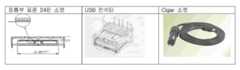
도 4는 무접점 충전기에서 24핀 커넥터를 사용하는 충전기, 어댑터, USB 포트를 입력으로 사용하는 실시예를 나타낸 도면.Figure 4 shows an embodiment using a charger, adapter, USB port using a 24-pin connector in a contactless charger as an input.
도 5는 2차측 코어를 무접점 충전용 배터리 팩(하드팩)의 구성도.5 is a configuration diagram of a battery pack (hard pack) for contactless charging of a secondary side core.
도 6은 휴대폰에 적용 가능한 무접점 충전용 세미 이너팩 구성도.Figure 6 is a semi-inner pack configuration for contactless charging applicable to a mobile phone.
도 7은 제1 실시예에 따른 무접점 충전용 내장형 배터리 팩 조립도(회로기판 탑면 배치).7 is an assembly view of a built-in battery pack for contactless charging according to the first embodiment (circuit board top surface arrangement).
도 8은 제2 실시예에 따른 무접점 충전용 내장형 배터리 팩 조립도(회로기판 탑면 배치).8 is an assembly view of a built-in battery pack for contactless charging according to a second embodiment (circuit board top surface arrangement).
도 9는 제3 실시예에 따른 무접점 충전용 내장형 배터리 팩 조립도(회로기판 측면 배치).9 is an assembled battery pack for contactless charging according to a third embodiment (circuit board side arrangement).
도 10은 무선 전력 수신 모듈을 가진 배터리 팩의 구성도.10 is a block diagram of a battery pack having a wireless power receiving module.
<도면의 주요 부분에 대한 부호의 설명><Explanation of symbols for the main parts of the drawings>
1: USB 커넥터 2a: USB 드라이버 회로1:
3: 메인 CPU(MPU 블록) 4:FET 구동 드라이브 회로3: Main CPU (MPU Block) 4: FET Drive Drive Circuit
5: LLC 풀브릿지 직렬 공진 컨버터 6: 1차측 코일5: LLC full bridge series resonant converter 6: primary side coil
7: 2차측 코일 8: 바이메탈7: secondary coil 8: bimetal
9: 먼지 및 냄새 감지 센서10: 이온 발생 장치9: dust and odor detection sensor 10: ion generator
11: 전류 피드백 회로 12: 온도 감지 회로11: current feedback circuit 12: temperature sensing circuit
13: 2차측 신호 피드백 회로14: 풀브릿지 정류 회로13: Secondary side signal feedback circuit 14: Full bridge rectifier circuit
15: ID와 이물질 감지, 충전 상태 피드백 충전 회로 on off 기능,15: ID and foreign material detection, charging status feedback charging circuit on off function,
신호-to-USB 변환 기능이 있는 회로(Adaptor Control Block) Circuit with Signal-to-USB Conversion (Adaptor Control Block)
16: 충전 회로17: 배터리 용량 체크 회로16: charging circuit 17: battery capacity check circuit
18: 배터리 보호 회로19: PTC와 배터리18: battery protection circuit 19: PTC and battery
20a: 휴대폰에 내장된 USB 회로2b: USB-to-IrDA 드라이버 회로20a: USB circuitry built into the
20b: 휴대폰에 내장된 IrDA회로20b: IrDA circuit embedded in the mobile phone
본 발명은 무선 데이타 통신과 전력 전송이 가능한 무접점 충전기 및 이를 이용한 휴대용 단말기에 관한 것으로, 특히 TC, TA, PC의 USB Port의 출력을 전원 입력으로 하는 유도기전력을 이용한 무접점 전력전송 장치에 관한 것으로 휴대용 단말기(휴대폰, PDA, MP3 player, DAB 또는 DMB 단말기, PMP, Handheld 단말기 등)와 PC간 무선 데이터 통신과 무선 충전을 동시에 가능하게 하는, 무선 데이타 통신과 전력 전송이 가능한 무접점 충전기 및 이를 이용한 휴대용 단말기에 관한 것이다.The present invention relates to a contactless charger capable of wireless data communication and power transmission, and a portable terminal using the same, and more particularly, to a contactless power transmission apparatus using induction electromotive force using the output of the USB port of TC, TA, PC as a power input. A contactless charger capable of wireless data communication and power transfer, which simultaneously enables wireless data communication and wireless charging between a portable terminal (mobile phone, PDA, MP3 player, DAB or DMB terminal, PMP, handheld terminal, etc.) and a PC. It relates to a portable terminal used.
또한, 충전하고자 하는 휴대용 단말기의 배터리 팩(2차측 무선충전 모듈이 내장된 팩) 이외의 다른 금속 이물질이 올려졌을 때 이를 감지하여 차단시킬 수 있는 이물질 감지 기능과 휴대용 단말기의 배터리 팩을 인식하여 충전상태를 인식할 수 있는 식별기능을 가지며, 과부하와 온도 프로텍션 기능을 가지는 무선 데이타 통신과 전력 전송이 가능한 무접점 충전기 및 이를 이용한 휴대용 단말기에 관한 것이다.In addition, the foreign material detection function that can detect and block when a metal foreign material other than the battery pack (pack with a built-in secondary wireless charging module) of the portable terminal to be charged is recognized and the battery pack of the portable terminal is recognized and charged The present invention relates to a contactless charger having an identification function capable of recognizing a state, capable of wireless data communication and power transmission having an overload and temperature protection function, and a portable terminal using the same.
종래에는 이종의 금속체가 무접점 충전기에 올려졌을 때, 유도 기전력에 의하여 상기 금속체가 와전류에 의한 손실이 열로 발생하여 과열이 되는 현상이 발생된다. 이는 유도기전력을 이용한 무접점 충전기의 안정성에 가장 큰 영향을 미치는 문제로 인식되어 왔다.Conventionally, when a heterogeneous metal body is placed on a contactless charger, a phenomenon in which the metal body causes heat loss due to eddy current due to induced electromotive force occurs, resulting in overheating. This has been recognized as the problem that most affects the stability of the contactless charger using induction electromotive force.
그러므로, 동전, 금속펜, 가위, 등 생활 속의 모든 금속체를 인식하여 전력을 차단하여 과열의 위험으로부터 안전장치를 반드시 구비해야 하는 문제점이 있었다.Therefore, there is a problem that must be equipped with a safety device from the risk of overheating by cutting off the power by recognizing all metal objects in the life such as coins, metal pens, scissors, and the like.
그러나, TC, TA, PC의 USB Port의 출력을 전원 입력으로 하는 유도 기전력을 이용한 무접점 전송 기술에 의해 휴대용 단말기(휴대폰, PDA, MP3 player, DAB 또는 DMB 단말기, PMP, Handheld 단말기 등)와 PC간 무선 데이터 통신과 무선 충전을 동시에 가능하게 하는 무접점 충전기를 제공하지 않았던 문제점이 있었다.However, portable terminals (mobile phones, PDAs, MP3 players, DAB or DMB terminals, PMPs, handheld terminals, etc.) and PCs are based on contactless transmission technology using induced electromotive force using the output of TC, TA, and PC USB ports as power inputs. There has been a problem in that a non-contact charger is provided which enables simultaneous wireless data communication and wireless charging.
본 발명은 종래 기술의 문제점을 해결하기 위해 제안된 것으로, 본 발명의 목적은 TC, TA, PC의 USB Port의 출력을 전원 입력으로 하는 유도기전력을 이용한 무접점 전력 전송에 의해 휴대용 단말기(휴대폰, PDA, MP3 player, DAB 또는 DMB 단말기, PMP, Handheld 단말기 등)와 PC간 무선 데이터 통신과 무선 충전을 동시에 가능하게 하는, 무선 데이타 통신과 전력 전송이 가능한 무접점 충전기 및 이를 이용한 휴대용 단말기를 제공하는 것이다.The present invention has been proposed to solve the problems of the prior art, an object of the present invention is a portable terminal (mobile phone, by contactless power transmission using induction electromotive force using the output of the USB port of TC, TA, PC as a power input) To provide wireless data communication and wireless charging between the PDA, MP3 player, DAB or DMB terminal, PMP, Handheld terminal, etc.) and PC at the same time, and to provide a contactless charger and a portable terminal using the same. will be.
또한, 본 발명의 다른 목적은, 충전하고자 하는 휴대용 단말기의 배터리 팩(2차측 무선충전 모듈이 내장된 팩) 이외의 다른 금속 이물질이 올려졌을 때 이를 감지하여 차단시킬 수 있는 이물질 감지 기능과, 휴대용 단말기의 배터리 팩을 인식하여 충전상태를 인식할 수 있는 식별기능을 가지며, 과부하와 온도 프로텍션 기능을 가지는, 무선 데이타 통신과 전력 전송이 가능한 무접점 충전기 및 이를 이 용한 휴대용 단말기를 제공하는 것이다.In addition, another object of the present invention, the foreign matter detection function that can detect and block when a metal foreign matter other than the battery pack (pack with a built-in secondary wireless charging module) of the portable terminal to be charged, and portable The present invention provides a contactless charger having an identification function capable of recognizing a battery pack of a terminal and recognizing a charging state, and having a function of overload and temperature protection, capable of wireless data communication and power transmission, and a portable terminal using the same.
본 발명의 목적을 달성하기 위하여, 본 발명에 따른 무선 데이타 통신과 전력 전송이 가능한 무접점 충전기 및 이를 이용한 휴대용 단말기는, 컴퓨터, 노트북의 USB 포트로 연결하기 위한 USB 커넥터; 상기 컴퓨터, 노트북과 USB 커넥터와 연결되어, 음악, 동영상, 데이타를 수신받아 USB 프로토콜로 에뮬레이션하기 위한 USB 드라이버 회로; 무접점 충전기(Wireless Charger)의 내부 소자를 제어하기 위한 메인 CPU(MPU 블록); 부츠트랩 게이트 드라이버(Bootstrap Gate Driver)를 포함하는 FET 구동 드라이브 회로(Gate Drive Block); LLC 풀브릿지 직렬 공진 컨버터(LLC Full-bridge Serial Resonator Converter); FPCB, PCB, 코일, 페라이트 코어로 구성된 분리형 변압기로써, 상기 메인 CPU(MPU 블록)의 제어에 따라 신호를 합성하여 무선으로 전송하여 휴대용 단말기에 내장된 배터리 팩의 2차측 코일로 전송하기 위한 1차측 코일; 모든 칩의 기능이 마비되었을 때, C-L 공진부에 직렬로 삽입되고, 코어가 과열되었을 때 끈을 수 있도록 삽입하여 안전장치를 확보하기 위한 바이메탈; 상기 무접점 충전기의 먼지 및 냄새를 감지하기 위한 먼지 및 냄새 감지 센서를 포함한다.In order to achieve the object of the present invention, a non-contact charger capable of wireless data communication and power transmission according to the present invention and a portable terminal using the same, a USB connector for connecting to a USB port of a computer, notebook; A USB driver circuit connected to the computer, the notebook and the USB connector, and configured to receive music, video and data and to emulate the USB protocol; A main CPU (MPU block) for controlling the internal elements of a wireless charger; A FET drive drive circuit including a bootstrap gate driver; LLC Full-bridge Serial Resonator Converter; This is a separate transformer composed of FPCB, PCB, coil, and ferrite core, and synthesizes the signals under the control of the main CPU (MPU block) and transmits them wirelessly to the secondary coil of the battery pack built in the portable terminal. coil; When all the functions of the chip is paralyzed, it is inserted in series to the C-L resonator, and the bimetal for securing the safety by inserting so that when the core is overheated; It includes a dust and odor detection sensor for detecting the dust and odor of the contactless charger.
상기 휴대용 단말기에 내장된 배터리 팩의 2차측 코일은, 상기 휴대용 단말기의 풀브릿지 정류 회로와 연결되는 것을 특징으로 한다.The secondary coil of the battery pack built in the portable terminal is connected to the full bridge rectifier circuit of the portable terminal.
상기 휴대용 단말기의 배터리 팩은, ID와 이물질 감지, 충전 상태 피드백 충 전 회로 on off 기능, 신호-to-USB 변환 기능이 있는 회로(Adaptor Control Block), 충전 회로(Charge Management Block), 배터리 용량 체크 회로(Fuel Gauge Control Block), 배터리 보호 회로(Prototection Control Block), PTC와 배터리, 및 휴대폰에 내장된 USB 회로를 포함한다.The battery pack of the portable terminal includes an ID and foreign material detection, a charge state feedback charging circuit on off function, a signal-to-USB conversion function (Adaptor Control Block), a charging circuit (Charge Management Block), and a battery capacity check. Circuits (Fuel Gauge Control Block), battery protection circuit (Prototection Control Block), PTC and battery, and USB circuitry embedded in the mobile phone.
본 발명의 다른 목적을 달성하기 위하여, 본 발명에 따른 무선 데이타 통신과 전력 전송이 가능한 무접점 충전기 및 이를 이용한 휴대용 단말기는, 컴퓨터, 노트북의 USB 포트로 연결하기 위한 USB 커넥터; 상기 컴퓨터, 노트북과 USB 커넥터와 연결되어, 음악, 동영상, 데이타를 수신받아 USB-to-IrDA 프로토콜로 에뮬레이션하기 위한 USB-to-IrDA 드라이버 회로; 무접점 충전기(Wireless Charger)의 내부 소자를 제어하기 위한 메인 CPU(MPU 블록); 부츠트랩 게이트 드라이버(Bootstrap Gate Driver)를 포함하는 FET 구동 드라이브 회로(Gate Drive Block); LLC 풀브릿지 직렬 공진 컨버터(LLC Full-bridge Serial Resonator Converter); FPCB, PCB, 코일, 페라이트 코어로 구성된 분리형 변압기로써, 상기 메인 CPU(MPU 블록)의 제어에 따라 신호를 합성하여 무선으로 전송하여 휴대용 단말기에 내장된 배터리 팩의 2차측 코일로 전송하기 위한 1차측 코일; 모든 칩의 기능이 마비되었을 때, C-L 공진부에 직렬로 삽입되고, 코어가 과열되었을 때 끈을 수 있도록 삽입하여 안전장치를 확보하기 위한 바이메탈; 상기 무접점 충전기의 먼지 및 냄새를 감지하기 위한 먼지 및 냄새 감지 센서; 부가적인 음이온 발생기능이나 세균 박멸을 위한 향균 스프레이가 분사하기 위한 이온 발생 장치; 2차측 무선 충전 모듈이 내장된 휴대용 단말기를 부하 변조(Load regulation)를 통하여 1차측 코일의 충전 모듈에서 ID를 인식하고, 2차측 정류단의 전압을 항상 정전압으로 제어할 수 있도록 1차측 주파수 자동 가변 알고리즘을 통하여 전류 피드백에 의한 안정적인 전력 제어를 하기 위한 전류 피드백 회로; 충전 칩의 온도를 감지하기 위한 온도 감지 회로; 및 2차측 코일의 신호를 피드백하기 위한 2차측 신호 피드백 회로를 포함한다.In order to achieve the other object of the present invention, a wireless contactless and a wireless charger capable of transmitting power and data according to the present invention and a portable terminal using the same, a USB connector for connecting to a USB port of a computer, notebook; A USB-to-IrDA driver circuit connected to the computer, the notebook and the USB connector and configured to receive music, video, and data and to emulate the USB-to-IrDA protocol; A main CPU (MPU block) for controlling the internal elements of a wireless charger; A FET drive drive circuit including a bootstrap gate driver; LLC Full-bridge Serial Resonator Converter; This is a separate transformer composed of FPCB, PCB, coil, and ferrite core, and synthesizes the signals under the control of the main CPU (MPU block) and transmits them wirelessly to the secondary coil of the battery pack built in the portable terminal. coil; When all the functions of the chip is paralyzed, it is inserted in series to the C-L resonator, and the bimetal for securing the safety by inserting so that when the core is overheated; A dust and odor detection sensor for detecting dust and odor of the contactless charger; Ion generating device for spraying the antibacterial spray for additional anion generating function or bacteria eradication; The primary terminal frequency is automatically changed so that the portable terminal with the secondary wireless charging module can recognize the ID in the charging module of the primary coil through load regulation and control the voltage of the secondary rectifier stage to constant voltage at all times. A current feedback circuit for stable power control by current feedback through an algorithm; A temperature sensing circuit for sensing the temperature of the charging chip; And a secondary side signal feedback circuit for feeding back a signal of the secondary side coil.
상기 휴대용 단말기의 배터리 팩은, ID와 이물질 감지, 충전 상태 피드백 충전 회로 on off 기능, 신호-to-USB 변환 기능이 있는 회로(Adaptor Control Block), 충전 회로(Charge Management Block), 배터리 용량 체크 회로(Fuel Gauge Control Block), 배터리 보호 회로(Prototection Control Block), PTC와 배터리, 및 휴대폰에 내장된 IrDA 회로를 포함한다.The battery pack of the portable terminal includes an ID and foreign material detection, a charge-state feedback charging circuit on off function, a signal-to-USB conversion function (Adaptor Control Block), a charging circuit (Charge Management Block), a battery capacity check circuit (Fuel Gauge Control Block), Battery Protection Circuit (Prototection Control Block), PTC and Battery, and IrDA circuitry embedded in mobile phones.
이하, 첨부된 도면을 참조로 본 발명의 바람직한 실시예를 상세히 설명하기로 한다.Hereinafter, exemplary embodiments of the present invention will be described in detail with reference to the accompanying drawings.
도 1은 본 발명의 실시예에 따른 코어-투-코어(Core-to-Core) 통신 방식을 이용한 무접점 충전기와 휴대용 단말기와 데이타 통신 및 전력을 전달하는 무접점 충전기(Wireless Charger)의 구성도이다.1 is a configuration diagram of a contactless charger using a core-to-core communication method and a contactless charger for transferring data and power with a portable terminal according to an embodiment of the present invention. to be.
상기 코어-투-코어 통신 방식을 이용한 무접점 충전기와 휴대용 단말기 간의 데이타 통신 및 전력을 전달하는 무접점 충전기는, 컴퓨터, 노트북의 USB 포트로 연결하기 위한 USB 커넥터(USB Connector)(1), 상기 컴퓨터, 노트북과 USB 커넥터와 연결되어, 음악, 동영상, 데이타를 수신받아 USB 프로토콜로 에뮬레이션하기 위한 USB 드라이버 회로(USB Emulation Control Block)(2a), 무접점 충전기(Wireless Charger)의 내부 소자를 제어하기 위한 메인 CPU(MPU 블록)(3), 부츠트랩 게이트 드라이버(Bootstrap Gate Driver)를 포함하는 FET 구동 드라이브 회로(Gate Drive Block)(4), LLC 풀브릿지 직렬 공진 컨버터(LLC Full-bridge Serial Resonator Converter)(5), FPCB, PCB, 코일, 페라이트 코어로 구성된 분리형 변압기로써, 상기 메인 CPU(MPU 블록)의 제어에 따라 신호를 합성하여 무선으로 전송하여 휴대용 단말기에 내장된 배터리 팩의 2차측 코일(7)로 전송하기 위한 1차측 코일(6), 모든 칩의 기능이 마비되었을 때, C-L 공진부에 직렬로 삽입되고, 코어가 과열되었을 때 끈을 수 있도록 삽입하여 안전장치를 확보하기 위한 바이메탈(Bimetal)(8), 상기 무접점 충전기의 먼지 및 냄새를 감지하기 위한 먼지 및 냄새 감지 센서(Dust & Smell Sensor Circuit)(9), 부가적인 음이온 발생기능이나 세균 박멸을 위한 향균 스프레이가 분사하기 위한 이온 발생 장치(Ionizer High voltage drive circuit Control Block)(10), 2차측 무선 충전 모듈이 내장된 휴대용 단말기를 부하 변조(Load regulation)를 통하여 1차측 코일의 충전 모듈에서 ID를 인식하고, 2차측 정류단의 전압을 항상 정전압으로 제어할 수 있도록 1차측 주파수 자동 가변 알고리즘을 통하여 전류 피드백에 의한 안정적인 전력 제어를 하기 위한 전류 피드백 회로(Current sensing block)(11), 충전 칩의 온도를 감지하기 위한 온도 감지 회로(Thermal Protection Safety Block)(12), 2차측 신호 피드백 회로(13)를 포함한다.The contactless charger for transferring data and power between the contactless charger and the portable terminal using the core-to-core communication method may include a USB connector (1) for connecting to a USB port of a computer or a laptop. Connects to a computer, laptop, and USB connector to control the internal components of a USB Emulation Control Block (2a) and a Wireless Charger to receive music, video and data and to emulate them with the USB protocol. Main drive (MPU block) (3), FET drive drive circuit (4) including Bootstrap Gate Driver, LLC Full-bridge Serial Resonator Converter (5), FPCB, PCB, coil, ferrite core is a separate transformer, the signal is synthesized according to the control of the main CPU (MPU block) and transmitted wirelessly to the portable terminal Primary coil (6) for transmission to secondary coil (7) of the loaded battery pack, inserted in series in CL resonator when all chip functions are paralyzed and inserted so that it can be pulled out when core overheats Bimetal (8) to secure safety device, Dust & Smell Sensor Circuit (9) to detect dust and odor of the contactless charger, additional anion generating function or bacteria eradication High voltage drive circuit control block (Ionizer) for spraying antimicrobial sprays for the air, and the portable terminal with the secondary wireless charging module are loaded from the charging module of the primary coil through load regulation. Current for stable power control by current feedback through primary frequency automatic variable algorithm to recognize ID and control voltage of secondary rectifier stage to constant voltage at all times A
상기 휴대용 단말기에 내장된 배터리 팩의 2차측 코일(7)은 휴대용 단말기의 풀브릿지 정류 회로(Rectification Block)(14)와 연결된다.The
상기 휴대용 단말기의 배터리 팩(Wireless charge-enabled Battery Pack)은 ID와 이물질 감지, 충전 상태 피드백 충전 회로 on off 기능, 신호-to-USB 변환 기능이 있는 회로(Adaptor Control Block)(15), 충전 회로(Charge Management Block)(16), 배터리 용량 체크 회로(Fuel Gauge Control Block)(17), 배터리 보호 회로(Prototection Control Block)(18), PTC와 배터리(19), 및 휴대폰에 내장된 USB 회로(20a)를 포함한다. A wireless charge-enabled battery pack of the portable terminal includes an ID and foreign substance detection, a charge feedback feedback charging circuit on off function, a signal-to-USB conversion function (adaptor control block) 15, a charging circuit (Charge Management Block) (16), Battery Capacity Check Circuit (Fuel Gauge Control Block) (17), Battery Protection Circuit (Prototection Control Block) (18), PTC and Battery (19), and USB circuits embedded in mobile phones ( 20a).
(1) PC의 USB 포트를 통한 무선 데이터 전송 및 충전 기능(1) Wireless data transfer and charging via USB port of PC
상기 무접점 충전기(Wireless Charger)는 컴퓨터(PC) 또는 노트북으로부터 저장된 음악, 동영상, 데이터 등을 USB 커넥터(1)를 통해 USB 프로토콜로 에뮬레이션 할 수 있는 USB 드라이버 회로(2) 및 메인 CPU(MPU)(3)를 사용하여 1차 측 코일(분리형 변압기: FPCB, PCB, Coil, Ferrite core로 구성된 변압기)(6)에 신호를 합성하여 무선으로 전송한다. 휴대용 단말기는 내장된 배터리 팩의 2차 측 코일(분리형 변압기: FPCB, PCB, Coil, Ferrite core로 구성된 변압기)(7)에서 전송된 신호를 FSK(Frequency Shift Keying, 주파수 편이 방식)를 통하여 신호를 분리하고, 이 데이타를 상기 휴대용 단말기의 저장매체(메모리)에 유선 USB 컨트롤러를 통하여 저장한다.The wireless charger includes a USB driver circuit (2) and a main CPU (MPU) capable of emulating music, video, data, and the like stored from a computer (PC) or a notebook through a USB protocol through a USB connector (1). Use (3) to synthesize the signal to the primary side coil (separate transformer: transformer consisting of FPCB, PCB, Coil, Ferrite core) (6) and transmit it wirelessly. The portable terminal transmits the signal transmitted from the secondary coil of the built-in battery pack (separable transformer: transformer consisting of FPCB, PCB, coil, and ferrite core) (7) through frequency shift keying (FSK). The data is stored in a storage medium (memory) of the portable terminal through a wired USB controller.
2차측 무선 충전모듈이 내장된 휴대용 단말기를 상기 무접점 충전기(Wireless Charger)에 근접시키면, 자동으로 컴퓨터 본체로부터 동기화되어 USB가 자동 접속 되고 ,휴대용 단말기의 저장매체 폴더가 팝업되어 음악(MP3 format), 동영상(avi, asf, dat format), 데이터를 무선으로 다운로드 할 수 있다.When the portable terminal with the built-in secondary wireless charging module is brought close to the wireless charger, the USB is automatically synchronized by the computer main body, and the storage media folder of the portable terminal is popped up to play the music (MP3 format). , Video (avi, asf, dat format) and data can be downloaded wirelessly.
또한, 무선 데이터 통신과 상관없이 상기 컴퓨터의 USB 포트의 전원을 이용하여 2차 측 무선 충전 모듈이 내장된 휴대용 단말기를 부하변조(Load regulation)를 통하여 ID를 발생하고, 1차 측 충전모듈에서 ID를 인식하고, 2차 측 정류단 전압을 항상 정전압 제어를 할 수 있도록 1차 측 주파수 자동 가변 알고리즘을 통하여 전력제어를 구현하면, 상기 무접점 충전기는 Vdrop에 의한 소비전력[Pdis=(Vout-Vbat)*Ichg]을 최소화하여 충전칩의 온도 상승을 억제함으로써 복잡하고 가격이 비싼 스위칭 충전용 IC를 사용하지 않고 리니어 충전용 IC를 사용할 수 있으며, 또한 배터리 팩의 내부 공간을 확보할 수 있다.In addition, irrespective of wireless data communication, an ID is generated through load regulation of a portable terminal with a secondary wireless charging module by using a power source of the USB port of the computer, and the ID is charged by the primary charging module. If the power control is implemented through the primary frequency automatic variable algorithm so that the constant voltage control of the secondary side rectifier stage is always performed, the contactless charger may consume power by Vdrop [Pdis = (Vout-Vbat). By minimizing) * Ichg], it is possible to use the linear charging IC without using complicated and expensive switching charging ICs by suppressing the temperature increase of the charging chip, and also to secure the internal space of the battery pack.
도 2는 본 발명에 따른 IrDA 송수신 모듈이 내장된 무접점 충전기를 나타낸 도면이다.2 is a view showing a contactless charger with a built-in IrDA transceiver module according to the present invention.
도 2를 참조하면, 상기 무접점 충전기(Wireless Charger)는 전원입력으로 컴퓨터나 노트북의 USB포트에 연결하면, 상기 무접점 충전기에 내장된 USB 통신프로토콜을 IrDA로 변환하는 컨트롤러와 IrDA 컨트롤러, 그리고 IrDA 트랜시버를 통하여 PC 또는 노트북으로부터 저장된 음악, 동영상, 데이터 등을 연동하여 휴대용 단말기(휴대폰, PDA, PMP, DMB단말기, MP3 등)와 데이터를 무선으로 상호 교환할 수 있고, 전력 전송을 비접촉 분리형 변압기를 이용하여 상기 휴대용 단말기로 에너지를 전달하여 배터리를 충전한다.Referring to FIG. 2, when the wireless charger is connected to a USB port of a computer or a notebook with a power input, a controller, an IrDA controller, and IrDA for converting a USB communication protocol built into the contactless charger into IrDA Transceivers can wirelessly exchange data with portable terminals (mobile phones, PDAs, PMPs, DMB terminals, MP3s, etc.) by interlocking music, video, data, etc. stored from PCs or laptops. The battery is charged by transferring energy to the portable terminal.
상기 무접점 충전기에 내장된 IrDA 포트와 상기 휴대용 단말기의 IrDA포트를 일치시켜 2차 측 무선 충전모듈이 내장된 휴대용 단말기를 상기 무접점 충전기에 근접시키면, 상기 무접점 충전기는 자동으로 컴퓨터 본체와 동기화되어 쌍방이 적 외선 통신이 가능하여 USB가 자동으로 접속되고, 휴대용 단말기의 저장매체 폴더가 팝업 되어 음악(MP3 format), 동영상(avi, asf, dat format) 등 데이터를 무선 다운로드 할 수 있다.By matching the IrDA port embedded in the contactless charger with the IrDA port of the portable terminal and bringing the portable terminal with the secondary wireless charging module close to the contactless charger, the contactless charger is automatically synchronized with the computer body. Infrared communication is possible for both parties, and USB is automatically connected, and the storage media folder of the portable terminal is popped up to download data such as music (MP3 format) and video (avi, asf, dat format) wirelessly.
상기 무접점 충전기는 무선 데이터 통신과 상관없이 컴퓨터의 USB 포트의 전원을 이용하여 2차측 무선 충전 모듈이 내장된 휴대용 단말기를 부하변조(Load regulation)를 통하여 ID를 발생하고 1차 측 충전모듈에서 ID를 인식하고, 2차 측 정류단 전압을 항상 정전압 제어를 할 수 있도록 1차 측 주파수 자동 가변 알고리즘을 통하여 전력제어를 구현하면, Vdrop에 의한 소비전력[Pdis=(Vout-Vbat)*Ichg]을 최소화하여 충전칩과 배터리의 표면 온도 상승을 억제함으로써 복잡하고 가격이 비싼 스위칭 충전용 IC를 사용하지 않고 리니어 충전용 IC를 사용할 수 있으며, 또한 리니어 충전용 IC를 사용하여 공간이 적게 차지하기 때문에 배터리 팩의 내부 공간을 확보하게 된다.The contactless charger generates an ID through a load regulation of a portable terminal with a secondary wireless charging module by using a power source of a USB port of a computer regardless of wireless data communication. If the power control is implemented through the primary frequency automatic variable algorithm so that the secondary rectifier voltage can be controlled at all times, the power consumption by Pdrop [Pdis = (Vout-Vbat) * Ichg] By minimizing the surface temperature rise of the charging chip and battery, it is possible to use the linear charging IC without using the complicated and expensive switching charging IC, and also use the linear charging IC to take up less space. This will free up space inside the pack.
도 3은 본 발명의 다른 실시예에 따른 무접점 충전기에 내장된 IrDA 포트와 휴대용 단말기와 적외선 통신 방식과 전력을 전달하는 무접전 충전기의 구성도이다.3 is a block diagram of an IRDA port embedded in a contactless charger, a portable terminal, and a contactless charger for delivering power to an infrared communication method according to another embodiment of the present invention.
도 1과 도 3의 차이점은, 도 1은 1차측 코일과 2차측 코일끼리 통신하여 USB 포트로 연결시키는 방식이고, 도 2는 1차측 충전기에 내장된 IrDA 모듈과 휴대용 단말기(예:휴대폰)에 내장된 IrDA 모듈끼리 통신하는 방식이다.Difference between FIG. 1 and FIG. 3 is a method of connecting a primary coil and a secondary coil to a USB port, and FIG. 2 illustrates an IrDA module built in a primary charger and a portable terminal (eg, a mobile phone). Built-in IrDA modules communicate with each other.
즉, 도 3은 도 1과 비교하면, 상기 무접점 충전기는 USB-to-IrDA 드라이버 회로(2b), 및 휴대폰에 내장된 IrDA 회로(20b)에 차이점이 있다.That is, FIG. 3 is different from FIG. 1 in that the contactless charger has a difference between the USB-to-
도 3에 도시된 바와 같이, 무접점 충전기에 내장된 IrDA 포트와 휴대용 단말기와 적외선 통신 방식과 전력을 전달하는 무접전 충전기는, USB 커넥터(USB Connector)(1), USB-to-IrDA 드라이버 회로(USB to IrDA Control Block)(2b), 메인 CPU(MPU 블록)(3), 부츠트랩 게이트 드라이버(Bootstrap Gate Driver)를 포함하는 FET 구동 드라이브 회로(Gate Drive Block)(4), LLC 풀브릿지 직렬 공진 컨버터(LLC Full-bridge Serial Resonator Converter)(5), 1차측 코일(6), 2차측 코일(7), 바이메탈(Bimetal)(8), 먼지 및 냄새 감지 센서(Dust & Smell Sensor Circuit)(9), 이온 발생 장치(Ionizer High voltage drive circuit Control Block)(10), 전류 피드백 회로(Current sensing block)(11), 온도 감지 회로(Thermal Protection Safety Block)(12), 및 2차측 신호 피드백 회로(13)를 포함한다.As shown in FIG. 3, an IRDA port embedded in a contactless charger and a non-contact charger that transmits power and infrared communication with a portable terminal include a
상기 휴대용 단말기에 내장된 2차측 코일(7)은 상기 휴대용 단말기의 풀브릿지 정류 회로(Rectification Block)(14)와 연결된다.The
상기 휴대용 단말기의 배터리 팩(Wireless charge-enabled Battery Pack)은 ID와 이물질 감지, 충전 상태 피드백 충전 회로 on off 기능, 신호-to-USB 변환 기능이 있는 회로(Adaptor Control Block)(15), 충전 회로(Charge Management Block)(16), 배터리 용량 체크 회로(Fuel Gauge Control Block)(17), 배터리 보호 회로(Prototection Control Block)(18), PTC와 배터리(19), 및 휴대폰에 내장된 IrDA 회로(20b)를 포함한다.A wireless charge-enabled battery pack of the portable terminal includes an ID and foreign substance detection, a charge feedback feedback charging circuit on off function, a signal-to-USB conversion function (adaptor control block) 15, a charging circuit (Charge Management Block) 16, Battery Capacity Check Circuit (Fuel Gauge Control Block) 17, Battery Protection Circuit (Prototection Control Block) 18, PTC and
(2) 이물질 감지 기능(2) Foreign material detection function
도 4는 무접점 충전기에서 24핀 커넥터를 사용하는 충전기, 어댑터, USB 포트를 입력으로 사용하는 실시예를 나타낸 도면이다.4 is a view showing an embodiment using a charger, an adapter, a USB port using a 24-pin connector in a contactless charger as an input.
이종의 금속체가 상기 무접점 충전기에 올려졌을 때, 유도 기전력에 의하여 상기 금속체가 와전류에 의한 손실이 열로 발생하여 과열이 되는 현상이 발생된다. 이러한 현상은 유도기전력을 이용한 무접점 충전기의 안정성에 가장 큰 영향을 미치는 문제로 인식되어 왔다. 그러므로, 동전, 금속펜, 가위, 등 생활 속의 모든 금속체를 인식하여 전력을 차단하여 과열의 위험으로부터 안전장치를 반드시 구비하여야만 한다.When a heterogeneous metal body is placed on the contactless charger, a phenomenon in which the metal body causes heat loss due to eddy current due to induced electromotive force occurs, resulting in overheating. This phenomenon has been recognized as the problem that most affects the stability of the contactless charger using induction electromotive force. Therefore, coins, metal pens, scissors, and all metal objects in the life must be recognized to cut off the power to provide a safety device from the risk of overheating.
1차 측 코어에서 2차 측 코어에 전력을 전달시키는 수단은 반파 또는 전파형 직렬/병렬 공진형 컨버터를 사용하여 LC공진을 시켜 전류를 정현파로 만들어 유도결합에 의해 2차 측에 전력을 전달하게 된다. 이때, 스위칭 주파수는 공진주파수 보다 높게 설정하여 소프트 스위칭이 되도록 한다. 1차 측 코어에서 일정한 인터벌(interval)을 두고 아주 짧은 시간 동안 PWM펄스를 인가하여 이물질이 올려져 있는지를 감지하는 매카니즘을 사용한다. 무부하시, 스위칭 주파수와 전류의 위상이 항상 90도를 이루는데, 이물질이 근접시키면 자기 인덕턴스의 변화에 의해 전류의 위상이 변화되고, 이 위상차의 레벨에 따라 이물질의 정도를 인식하며 전력을 인가하여 일정시간 동안 ID를 체크하여 궤환된 ID 신호가 감지되지 않거나 상이한 ID가 인식이 되면, 이물질로 인식하여 무접전 충전기 시스템을 shut-down 시켜 안정성을 확보한다.The means for transferring power from the primary core to the secondary core is LC resonant using half-wave or full-wave series / parallel resonant converter to make the current sinusoidal to transfer power to the secondary side by inductive coupling. do. At this time, the switching frequency is set higher than the resonance frequency so that soft switching. A mechanism is used to detect whether foreign matter is raised by applying a PWM pulse for a very short time at a constant interval in the primary core. At no load, the switching frequency and the phase of the current are always 90 degrees. When the foreign matter is close, the phase of the current is changed by the change of the magnetic inductance, and the power is applied by recognizing the degree of the foreign matter according to the level of the phase difference. If the ID signal is not detected by checking the ID for a certain time or a different ID is recognized, it recognizes it as a foreign material and shuts down the contactless charger system to secure stability.
또한, 충전 중 이물질 감지는 복잡한 기술이 요구되는데 충전이 되면서 전력 은 점점 떨어지게 되어 있다. 이 전력 곡선에 히스테리시스를 두어 이물질이 올려졌을 때, 히스테리시스 구간을 넘어가면 이물질로 인식하여 shut-down시키는 알고리즘이 사용하여 구현하였다.In addition, foreign matter detection during charging requires a complex technology, the power is gradually reduced as it is being charged. The hysteresis is placed on this power curve, and when the foreign matter is raised, the algorithm that recognizes the foreign matter and shuts down when the hysteresis section is crossed is implemented.
본 발명은 상기 무접점 충전기의 안전장치와 무선충전용 모듈이 내장된 배터리 팩의 안전성 및 배터리 상태 감시기능을 갖춘 무선 충전 솔루션을 제공한다.The present invention provides a wireless charging solution having a safety and battery condition monitoring function of a battery pack in which the safety device of the contactless charger and a module for wireless charging are incorporated.
상기 무접점 충전기는 기본적으로 코일의 온도와 구동 칩의 온도를 검출하여 상시 온도가 45도 이상일 경우, Shut-down시키는 기능과 과전류, 과전압에 대한 보호 기능을 칩에 내장하고, 또한 퓨즈(Fuse)를 내장하여 과전류를 차단한다. 그리고, 상기 무접점 충전기는 모든 칩의 기능이 마비되었을 때, C-L 공진부에 직렬로 바이메탈(Bimetal)을 삽입하여 코어가 과열되었을 때 끈을 수 있도록 삽입하여 안전장치를 확보하였다.The contactless charger basically detects the coil temperature and the driving chip temperature and shuts down when the temperature is always higher than 45 degrees, and incorporates a function to protect against overcurrent and overvoltage in the chip, and also fuses. Built-in circuit breaks overcurrent. In addition, the contactless charger is secured by inserting a bimetal (Bimetal) in series in the C-L resonator unit when all the functions of the chip is paralyzed so that it can be turned off when the core is overheated.
배터리 팩 내부의 안전장치는 충전회로에 내장된 온도센서가 있어서 외부에 연결된 NTC가 온도변화에 따라 저항값이 변동되어 분배된 전압을 피드백 받아, 기 설정된 온도 이상이 되면 충전을 차단하는 기능을 내장하고 있다. 또한, PCM이라는 보호회로에 의해 과전류, 과전압, 과방전, 단락 등으로부터 배터리를 보호하고 PTC 또는 바이메탈(Bimetal)을 사용하여 과전류와 온도에 의해 차단되어 배터리를 보호한다. 그리고, 배터리 팩에 내장된 ID 칩에서 충전 중 배터리 내부의 오동작이 발생했을 경우, 상기 무접점 충전기에 로드 레귤레이션을 통해 신호를 전송하고, 상기 무접점 충전기에서 FSK를 통해 신호를 받아서 스위칭을 차단하여 전력공급을 중단하는 메커니즘을 가진다. 상기 무접점 충전용 배터리 팩이 상기 무접점 충전기에 올려지면 배터리 팩에 내장된 ID칩이 동작하여 무부하 상태에서 로드 레귤레이션을 하여 충전 스타트 ID를 무접점 충전기에 전송하고, 상기 무접점 충전기는 그 신호를 피드백 받아서 ID가 일치하는지 확인하고 일치하면 풀 파워모드로 전력을 배터리 팩에 공급한다. 동시에 부가적인 음이온 발생기능이나 세균 박멸을 위한 향균 스프레이가 분사되고, LCD 디스플레이 장치에 충전이 되고 있다는 표시가 나타난다. 그리고, 배터리 팩이 만충전이 되면, 충전용 IC에서 출력된 만충전 신호를 ID칩에서 받아서 만충전 ID를 상기 무접점 충전기에 로드 레귤레이션을 통하여 전송하고, 이 신호를 피드백 받아 배터리 팩이 충전이 완료되었다는 것을 디스플레이 장치를 통하여 표시한다.The safety device inside the battery pack has a built-in temperature sensor in the charging circuit so that the NTC connected to the outside changes the resistance value according to the temperature change and feeds back the divided voltage. Doing. In addition, the PCM protection circuit protects the battery from overcurrent, overvoltage, overdischarge, short circuit, and the like, and protects the battery by being blocked by overcurrent and temperature using PTC or Bimetal. If a malfunction occurs inside the battery during charging, the ID chip embedded in the battery pack transmits a signal to the contactless charger through load regulation, and receives a signal through the FSK from the contactless charger to block switching. It has a mechanism to stop the power supply. When the contactless rechargeable battery pack is placed on the contactless charger, the ID chip embedded in the battery pack operates to perform load regulation in a no-load state to transmit a charge start ID to the contactless charger, and the contactless charger receives the signal. The feedback is then checked to see if the IDs match and if so, power is supplied to the battery pack in full power mode. At the same time, antimicrobial sprays for additional anion generation or bacteria eradication are sprayed and an indication is displayed on the LCD display device. When the battery pack is fully charged, the charger receives the full charge signal output from the charging IC from the ID chip and transmits the full charge ID to the contactless charger through load regulation, and the battery pack is fully charged by receiving the feedback. Display via the display device.
(3) 충전기, 어댑터, USB 포트를 입력으로 하는 24핀 커넥터를 사용하는 무접점 충전기(3) Solid-state charger with 24-pin connector that accepts chargers, adapters, and USB ports
24핀 표준 커넥터를 사용하여 여행용 충전기가 꽂일 경우, 1번 핀에 할당된 특정 ID저항을 통해 항상 4.2V를 21, 22번 핀을 통해 입력 받고, 어댑터가 꽂일 경우 4, 5번 핀을 통해 전원을 입력 받고, USB 포트에 꽂일 경우 16번 핀을 통해 전원을 입력 받을 수 있으며, 상기 무접점 충전기는 입력전원이 4V에서 5.5V에서 동작 가능하다.When the travel charger is plugged in using a 24-pin standard connector, it always receives 4.2V through
상기 24핀 표준 커넥터를 사용하는 어댑터를 사용하여 2개의 휴대용 단말기를 동시에 충전시킬 수 있는 도킹 스테이션을 구성하여 상기 무접점 충전기를 2개 연결하여 각각 휴대용 단말기 2대를 동시에 충전시킬 수 있다.By using an adapter using the 24-pin standard connector, a docking station configured to simultaneously charge two portable terminals may be configured to connect two contactless chargers to charge two portable terminals at the same time.
여기서 강조해야 될 것은 1) 일반적으로 비접촉 변압기의 경우 기존 변압기 와 달리 큰 공극을 갖기 때문에 자화인덕턴스는 공극이 없는 변압기에 비해 상대적으로 작고, 누설인덕턴스는 상대적으로 크기 때문에 기존 직렬 공진형 컨버터를 사용했을 경우 부하 변화에 대한 많은 순환전류가 흐르는 단점을 가지게 된다. 뿐만 아니라 2차측 정류다이오드의 연속적인 전류에 의해 다이오드의 역 회복 특성에 따른 스위칭 손실이 발생한다는 단점이 있다. 이러한 문제점을 개선하기 위해 비접촉 변압기용 풀브릿지 LLC 직렬 공진형 컨버터(5)를 적용하여 스위칭 주파수는 공진주파수보다 낮은 주파수에서 동작하여 기존 직렬 공진형 컨버터를 사용한 경우보다 순환전류를 많이 줄일 수 있고, 2차 측 정류다이오드에 불연속 전류가 흐르기 때문에 다이오드의 스위칭 손실을 줄일 수 있는 장점을 가진다.It should be emphasized that: 1) In general, non-contact transformers have large air gaps unlike conventional transformers. Therefore, the magnetization inductance is relatively small compared to the transformer without air gap, and the leakage inductance is relatively large. In this case, there is a disadvantage that a lot of circulating current flows for the load change. In addition, there is a disadvantage in that the switching loss occurs due to the reverse recovery characteristic of the diode by the continuous current of the secondary rectifier diode. In order to solve this problem, by applying the full bridge LLC series resonant converter (5) for a non-contact transformer, the switching frequency is operated at a frequency lower than the resonant frequency to reduce the circulating current much more than using the conventional series resonant converter, Discontinuous current flows through the secondary rectifier diode, which reduces the switching losses of the diode.
1차측 코일과 2차측 코일은 원형, 사각 등 모든 형태의 다양한 코어를 사용될 수 있다.The primary and secondary coils may use a variety of cores of all types, such as round and square.
(4) 2차 측 코어를 내장하는 방법에 따른 무접점 충전용 배터리 팩을 제조하는 구성 방법(4) A method of manufacturing a contactless rechargeable battery pack according to a method of embedding a secondary side core
(가) 하드팩 : 2차 측 코어와 자기장 차폐 실드, 정류회로, 충전회로(스위칭 또는 리니어 충전 회로), 무선 통신 ID 인식 회로, 보호회로, 배터리로 구성된다.(A) Hard pack: consisting of secondary core, magnetic shield shield, rectifier circuit, charging circuit (switching or linear charging circuit), wireless communication ID recognition circuit, protection circuit and battery.
도 5는 2차측 코어를 내장하는 방법에 따른 무접점 충전용 배터리 팩(하드팩:올인원 배터리팩)의 구성도이다.5 is a configuration diagram of a contactless rechargeable battery pack (hard pack: all-in-one battery pack) according to a method of embedding a secondary side core.
올인원 배터리팩은 2차 측 코어(코일 또는 코어방식 포함)(31), 정류회로(Rectification Block)(32), LDO+ID(TX, RX통신)+FET 드라이브+배터리 충전 상태 입력(Empty, Full 신호) 기능+오실레이터+충전회로 enable 또는 disable할 수 있는 포트를 내장한 어댑터 제어 블록(Adaptor Control Block)(33), 배터리 보호회로(PCM)(34), PTC와 배터리 블록(35), 충전회로(36), 휴대폰과 연결되는 단자(37)를 포함한다.All-in-one battery pack includes secondary core (including coil or core) 31,
(나) 내장형 배터리 팩(B) Internal battery pack
상기 휴대용 단말기는 케이스 커버에 2차측 코어와 자기장 차폐 실드를 내장하고(코어를커버에 사출 성형하거나 보호 케이스를 만들어서 초음파 융착하는 방법 사용), 휴대용 단말기와 연결될 수 있는 단자를 만들어 이 단자를 통하여 연결된 휴대용 단말기의 내장 회로에 정류회로, 무선 ID 인식회로를 부가하고, 상기 휴대용 단말기에 내장된 DC/DC 컨버터와 충전회로를 그대로 사용하여 내장된 배터리팩과 연결된 단자를 통하여 충전한다.The portable terminal has a secondary core and a magnetic shielding shield built into the case cover (using a method of ultrasonically fusion by core injection molding or a protective case on the cover), and a terminal which can be connected to the portable terminal is connected to the portable terminal. A rectifier circuit and a wireless ID recognition circuit are added to the built-in circuit of the portable terminal, and the DC / DC converter and the charging circuit built in the portable terminal are used as it is to charge through a terminal connected to the built-in battery pack.
상기 휴대용 단말기에 내장된 배터리 팩은, 2차측 코어와 자기장 차폐 실드, 정류회로, 무선 통신 ID인식회로, 보호회로, 배터리를 내장하고, 상기 휴대용 단말기와 정류회로 출력, 접지, 배터리 양극, 충전상태 핀 등의 연결 단자를 만들고 휴대용 단말기에 내장된 DC/DC 컨버터와 충전회로를 그대로 사용하여 배터리와 연결된 단자를 통하여 충전한다.The battery pack included in the portable terminal includes a secondary core, a magnetic shielding shield, a rectifier circuit, a wireless communication ID recognition circuit, a protection circuit, and a battery, and the portable terminal and rectifier circuit output, ground, battery positive electrode, and charging state. Make a connection terminal such as a pin and charge it through the terminal connected to the battery using the DC / DC converter and the charging circuit built in the portable terminal as it is.
도 6에 도시된 바와 같이, 휴대폰에 적용 가능한 무접점 충전용 세미 이너팩은 2차 측 코어(코일 또는 코어방식 포함)(41), 정류회로(Rectification Block)(42), LDO+ID(TX, RX통신)+FET 드라이브+배터리 충전 상태 입력(Empty, Full 신호) 기능+오실레이터+충전회로 enable 또는 disable할 수 있는 포트를 내장한 어댑터 제어 블록(Adapter Control Block)(43), 배터리 보호회로(PCM)(44), PTC와 배 터리 블록(45), GSM 휴대폰에 내장된 DC/DC 컨버터(46), 및 GSM휴대폰에 내장된 충전회로(47)를 포함한다.As shown in FIG. 6, the semi-inner pack for contactless charging applicable to a mobile phone includes a secondary side core (including coil or core type) 41, a
여기서, 상기 휴대폰이라고 명칭함은 휴대폰에 DC/DC컨버터와 충전회로가 내장된 휴대 전화기(예:GSM 휴대폰)를 말한다.Here, the term "mobile phone" refers to a mobile phone (eg, GSM mobile phone) in which a DC / DC converter and a charging circuit are embedded in the mobile phone.
무접점 충전기에 무접점 충전용 세미 이너팩을 내장한 GSM 휴대폰을 올려놓으면 무접점 충전기에서 전력을 발생시켜서 2차 측 배터리에 전력을 전송한다.When a GSM mobile phone with a semi-inner pack for contactless charging is placed on a contactless charger, the contactless charger generates power to transfer power to the secondary battery.
2차 측 배터리는 (41)에서 AC 전력을 받아서 정류회로(42)에서 정류를 하여 DC로 만들고, 어댑터 제어 블록(43)에서 RXD핀을 통해 전압이 5.5V이상이면 TXD핀을 통해 상기 무접점 충전기에 전력을 줄이기 위한 Power save 코드를 발생시켜 전달하고, 2차 측 전력이 5V 정도로 파라미터(주파수)를 조절한다. 이 경우를 반복하여 2차 측이 최적의 전압 조건(5V)이 되면 ID를 발생시키고, 무접점 충전기의 ID와 일치하면 상기 무접점 충전기에서 전력을 발생시킨다. 그렇지 않으면, 전력을 차단하고 절전 모드로 들어가거나 이물질이 올려졌을 경우 ID를 발생시키지 않기 때문에 에러를 발생시켜 전력을 차단한다.The secondary battery receives AC power at 41 and rectifies at
도 7은 제1 실시예에 따른 무접점 충전용 내장형 배터리 팩 조립도(회로기판 탑면 배치)이다.FIG. 7 is an assembly view (circuit board top surface arrangement) of a built-in battery pack for contactless charging according to a first embodiment.
제1 실시예에 따른 상기 무접점 충전용 내장형 배터리 팩은 A/S 라벨(①), 상부 케이스(Top case)(②), 무접점 충전용 PCB 보드(③), (-)Ni-Plate(④), PTC 또는 바이메탈(⑤), 리드선(⑥), (+)Ni-Plate(⑦), 보조 케이스(⑧), Nomax 테이프(⑨), 정류부 보드(⑩), 셀(⑪), 2차측 코일(⑫), 하부 케이스(Bottom case)(⑬ ), 및 라벨(⑭)을 구비한다.The built-in battery pack for contactless charging according to the first embodiment includes an A / S label (①), a top case (②), a contactless charging PCB board (③), and (-) Ni-Plate ( ④), PTC or bimetal (⑤), lead wire (⑥), (+) Ni-Plate (⑦), auxiliary case (⑧), Nomax tape (⑨), rectifier board (⑩), cell (⑪), secondary side A coil, a bottom case, and a label.
도 8은 제2 실시예에 따른 무접점 충전용 내장형 배터리 팩 조립도(회로기판 탑면 배치)이다.FIG. 8 is an assembly view (circuit board top surface arrangement) of a built-in battery pack for contactless charging according to a second embodiment.
제2 실시예에 따른 상기 무접점 충전용 내장형 배터리 팩은 A/S 라벨(①), 상부 케이스(Top case)(②), 무접점 충전용 PCB 보드(③), (-)Ni-Plate(④), PTC 또는 바이메탈(⑤), 리드선(⑥), (+)Ni-Plate(⑦), 보조 케이스(hot melt 방식으로 충진할 수 있음)(⑧), Nomax 테이프(⑨), 연결 보드(⑩'), 셀(⑪), 2차측 코일(⑫), 하부 케이스(Bottom case)(⑬), 및 라벨(⑭)을 구비한다.The built-in battery pack for contactless charging according to the second embodiment includes an A / S label (①), a top case (②), a contactless charging PCB board (③), and (-) Ni-Plate ( ④), PTC or bimetal (⑤), lead wire (⑥), (+) Ni-Plate (⑦), auxiliary case (can be filled by hot melt method) (⑧), Nomax tape (⑨), connection board ( VII '), a cell, a secondary coil, a bottom case, and a label.
도 9는 제3 실시예에 따른 무접점 충전용 내장형 배터리 팩 조립도(회로기판 측면 배치)이다.9 is an assembly view (circuit board side surface arrangement) of a built-in battery pack for contactless charging according to a third embodiment.
제3 실시예에 따른 상기 무접점 충전용 내장형 배터리 팩은 A/S 라벨(71), 상부 케이스(Top case)(72), 무접점 충전용 PCB 보드(73), (-)Ni-Plate(74), PTC 또는 바이메탈(75), 리드선(76), (+)Ni-Plate(77), 보조 케이스(hot melt 방식으로 충진할 수 있음)(78), Nomax 테이프(79), 연결 보드(80), 셀(81), 2차측 코일(82), 하부 케이스(Bottom case)(83), 및 라벨(84)을 구비한다.The built-in battery pack for contactless charging according to the third embodiment includes an A /
도 10은 무선 전력 수신 모듈을 가진 배터리 팩의 구성도이다.10 is a configuration diagram of a battery pack having a wireless power receiving module.
코일, 파인메탈, 박막알루미늄(호일 등), 리튬이온 또는 리튬폴리머로 된 배터리팩은 자기장을 100% 차단하기 위해 박막알루미늄을 넣어서 셀에 영향이 없도록 하여 셀의 사이클이 500회까지 충방전 가능하다. 여기서, 코일의 형상은 모든 형태의 코일을 포함한다.Battery packs made of coil, fine metal, thin film aluminum (foil, etc.), lithium ion or lithium polymer can be charged and discharged up to 500 cycles by inserting thin film aluminum to block 100% of the magnetic field so that the cell is not affected. . Here, the shape of the coil includes all types of coils.
상술한 바와 같이, 본 발명의 바람직한 실시예를 참조하여 설명하였지만, 해당 기술 분야의 숙련된 당업자는 하기의 특허청구범위에 기재된 본 발명의 사상 및 영역으로부터 벗어나지 않는 범위 내에서 본 발명을 다양하게 수정 또는 변형하여 실시할 수 있다.As described above, although described with reference to a preferred embodiment of the present invention, those skilled in the art various modifications of the present invention without departing from the spirit and scope of the invention described in the claims below Or it may be modified.
이상에서 설명한 바와 같이, 본 발명에 따른 무선 데이타 통신과 전력 전송이 가능한 무접점 충전기 및 이를 이용한 휴대용 단말기는 TC, TA, PC의 USB Port의 출력을 전원 입력으로 하는 유도기전력을 이용한 무접점 전력 전송에 의해 휴대용 단말기(휴대폰, PDA, MP3 player, DAB 또는 DMB 단말기, PMP(Portable Music Player), Handheld 단말기 등)와 컴퓨터(PC)간 무선 데이터 통신과 무선 충전을 동시에 가능하게 한다.As described above, the contactless charger capable of wireless data communication and power transmission and the portable terminal using the same according to the present invention, the contactless power transmission using induction electromotive force using the output of the USB port of TC, TA, PC as a power input This enables wireless data communication and wireless charging between portable terminals (mobile phones, PDAs, MP3 players, DAB or DMB terminals, portable music players, handheld terminals, etc.) and computers (PCs) at the same time.
또한, 본 발명에 따른 무접점 충전기는 충전하고자 하는 휴대용 단말기의 배터리 팩(2차측 무선충전 모듈이 내장된 팩) 이외의 다른 금속 이물질이 올려졌을 때, 이를 감지하여 차단시킬 수 있는 이물질 감지 기능과, 휴대용 단말기의 배터리 팩을 인식하여 충전상태를 인식할 수 있는 식별기능을 가지며, 과부하와 온도 프로텍션 기능을 제공하는 효과가 있다.In addition, the contactless charger according to the present invention has a foreign material detection function that can detect and block when other metal foreign matter other than the battery pack (pack with a built-in secondary wireless charging module) of the portable terminal to be charged; In addition, it has an identification function for recognizing a battery pack of a portable terminal to recognize a charging state, and has an effect of providing an overload and a temperature protection function.
Claims (25)
Translated fromKoreanPriority Applications (1)
| Application Number | Priority Date | Filing Date | Title |
|---|---|---|---|
| KR1020060064097AKR100806562B1 (en) | 2006-07-07 | 2006-07-07 | Contactless charging system |
Applications Claiming Priority (1)
| Application Number | Priority Date | Filing Date | Title |
|---|---|---|---|
| KR1020060064097AKR100806562B1 (en) | 2006-07-07 | 2006-07-07 | Contactless charging system |
Publications (2)
| Publication Number | Publication Date |
|---|---|
| KR20080005020Atrue KR20080005020A (en) | 2008-01-10 |
| KR100806562B1 KR100806562B1 (en) | 2008-02-28 |
Family
ID=39215584
Family Applications (1)
| Application Number | Title | Priority Date | Filing Date |
|---|---|---|---|
| KR1020060064097AActiveKR100806562B1 (en) | 2006-07-07 | 2006-07-07 | Contactless charging system |
Country Status (1)
| Country | Link |
|---|---|
| KR (1) | KR100806562B1 (en) |
Cited By (16)
| Publication number | Priority date | Publication date | Assignee | Title |
|---|---|---|---|---|
| WO2009133985A1 (en)* | 2008-04-28 | 2009-11-05 | Chun-Kil Jung | Wireless power charging system |
| KR100976161B1 (en)* | 2008-02-20 | 2010-08-16 | 정춘길 | Contactless charging system and its charging control method |
| KR100976154B1 (en)* | 2009-09-29 | 2010-08-17 | 주식회사 한림포스텍 | Non-contact charging system with charging current control function by input power |
| KR20100128395A (en)* | 2009-05-28 | 2010-12-08 | 장지환 | Non-contact power transmission device and method |
| KR101110282B1 (en)* | 2010-07-16 | 2012-02-15 | 정춘길 | Contactless power transmission control method of a contactless power receiver and a contactless power transmitter |
| US8373388B2 (en) | 2009-12-11 | 2013-02-12 | Electronics And Telecommunications Research Institute | Portable device and battery charging method thereof |
| WO2013022207A1 (en)* | 2011-08-05 | 2013-02-14 | Samsung Electronics Co., Ltd. | Wireless power transmission system, and method and apparatus for allocating communication channel and transmitting power in wireless power transmission system |
| KR101237365B1 (en)* | 2011-04-07 | 2013-02-28 | 이티에이치주식회사 | Transformer Type Non-Contact Charging Device Having Hands-Free Function |
| US8400248B2 (en) | 2010-10-20 | 2013-03-19 | Electronics And Telecommunications Research Institute | Wireless power transfer device |
| KR20130089479A (en)* | 2012-02-02 | 2013-08-12 | 엘지전자 주식회사 | Connecting system between mobile terminal and connecting device |
| KR101386650B1 (en)* | 2012-07-06 | 2014-04-21 | 전자부품연구원 | Method of detecting obstacles in a wireless power transmission system using magnetic resonance induction |
| US9083178B2 (en) | 2011-05-17 | 2015-07-14 | Samsung Electronics Co., Ltd. | Apparatus for and method of protecting wireless-coupled power devices from overvoltage, overcurrent, and overtemperature using hysteresis |
| US9871397B2 (en) | 2012-04-26 | 2018-01-16 | Lg Innotek Co., Ltd. | Wireless power receiver and power control method thereof |
| CN113366726A (en)* | 2018-04-02 | 2021-09-07 | 劲量品牌有限公司 | Portable electrical device with integrated charger |
| CN117713394A (en)* | 2024-02-06 | 2024-03-15 | 深圳今翔科技有限公司 | Wireless power supply control circuit and method applied to power supply equipment and power supply equipment |
| US12322971B2 (en) | 2008-12-12 | 2025-06-03 | Intel Corporation | Non-contact power receiver apparatus |
Families Citing this family (13)
| Publication number | Priority date | Publication date | Assignee | Title |
|---|---|---|---|---|
| KR100976231B1 (en)* | 2008-05-23 | 2010-08-17 | 고려대학교 산학협력단 | Wireless power supply control system |
| KR101373208B1 (en) | 2009-05-28 | 2014-03-14 | 한국전자통신연구원 | Electric device, wireless power transmission device and power transmission method thereof |
| KR101110325B1 (en)* | 2009-09-22 | 2012-02-15 | 전자부품연구원 | Wireless Charging System Using Resonance and Magnetic Field Communication |
| KR101071933B1 (en)* | 2009-10-07 | 2011-10-10 | 한국에너지기술연구원 | Electric vehicle charging and discharging system and method using the contactless power transmission method |
| KR101084904B1 (en)* | 2009-10-07 | 2011-11-18 | 삼성전기주식회사 | Wireless power transceiver with communication function and wireless power transmission / reception method thereof |
| KR101072276B1 (en)* | 2009-10-21 | 2011-10-11 | 유노시스템 주식회사 | charging and communication system in wireless |
| KR101394963B1 (en) | 2010-07-29 | 2014-05-16 | 한국전자통신연구원 | Wireless power transmitter, wireless power receiver, and method for wireless power transfer using them |
| KR101225090B1 (en) | 2011-01-25 | 2013-01-22 | 전자부품연구원 | Multi-node wireless charging base station and charging method using magnetic resonance induction |
| KR101786945B1 (en) | 2011-07-22 | 2017-10-19 | 한국전자통신연구원 | Power transmission apparatus and power reception apparatus |
| KR102450606B1 (en) | 2015-09-25 | 2022-10-05 | 주식회사 위츠 | Apparatus for receiving power wirelessly and power supply apparatus using the same |
| KR102589544B1 (en) | 2016-12-12 | 2023-10-17 | 삼성전자주식회사 | Electronic device for wirelessly receiving power and method for controlling thereof |
| KR102643465B1 (en) | 2017-01-17 | 2024-03-05 | 삼성디스플레이 주식회사 | Display device and driving method thereof |
| US11011945B2 (en) | 2018-12-21 | 2021-05-18 | Western Digital Technologies, Inc. | Systems and methods for wireless charging and wired data transfer |
Family Cites Families (2)
| Publication number | Priority date | Publication date | Assignee | Title |
|---|---|---|---|---|
| JPH11187143A (en) | 1997-12-25 | 1999-07-09 | Oki Electric Ind Co Ltd | Method and device for transferring data for personal communication terminal |
| KR20020035242A (en)* | 2000-11-06 | 2002-05-11 | 조규형 | Charger for use in a portable device |
- 2006
- 2006-07-07KRKR1020060064097Apatent/KR100806562B1/enactiveActive
Cited By (27)
| Publication number | Priority date | Publication date | Assignee | Title |
|---|---|---|---|---|
| US12348056B2 (en) | 2008-02-20 | 2025-07-01 | Intel Corporation | Apparatus of non-contact power receiver utilizing transmission of a power adjustment request to a non-contact power transmitter |
| US9142995B2 (en) | 2008-02-20 | 2015-09-22 | Hanrim Postech Co., Ltd. | Apparatus and method for controlling power transmission in non-contact power charging system based on charge information received from the receiving apparatus |
| US8030887B2 (en) | 2008-02-20 | 2011-10-04 | Chun-Kil Jung | Non-contact power charging system and control method thereof |
| KR100976161B1 (en)* | 2008-02-20 | 2010-08-16 | 정춘길 | Contactless charging system and its charging control method |
| US11387677B2 (en) | 2008-02-20 | 2022-07-12 | Intel Corporation | Non-contact power charging system and control method thereof based on foreign substance detection |
| USRE46046E1 (en) | 2008-02-20 | 2016-06-28 | Intel Corporation | Non-contact power charging system and control method thereof |
| US8115449B2 (en) | 2008-04-28 | 2012-02-14 | Chun-Kil Jung | Wireless power charging system |
| WO2009133985A1 (en)* | 2008-04-28 | 2009-11-05 | Chun-Kil Jung | Wireless power charging system |
| US12322971B2 (en) | 2008-12-12 | 2025-06-03 | Intel Corporation | Non-contact power receiver apparatus |
| KR20100128395A (en)* | 2009-05-28 | 2010-12-08 | 장지환 | Non-contact power transmission device and method |
| KR100976154B1 (en)* | 2009-09-29 | 2010-08-17 | 주식회사 한림포스텍 | Non-contact charging system with charging current control function by input power |
| US8373388B2 (en) | 2009-12-11 | 2013-02-12 | Electronics And Telecommunications Research Institute | Portable device and battery charging method thereof |
| KR101110282B1 (en)* | 2010-07-16 | 2012-02-15 | 정춘길 | Contactless power transmission control method of a contactless power receiver and a contactless power transmitter |
| US8400248B2 (en) | 2010-10-20 | 2013-03-19 | Electronics And Telecommunications Research Institute | Wireless power transfer device |
| KR101237365B1 (en)* | 2011-04-07 | 2013-02-28 | 이티에이치주식회사 | Transformer Type Non-Contact Charging Device Having Hands-Free Function |
| US9083178B2 (en) | 2011-05-17 | 2015-07-14 | Samsung Electronics Co., Ltd. | Apparatus for and method of protecting wireless-coupled power devices from overvoltage, overcurrent, and overtemperature using hysteresis |
| WO2013022207A1 (en)* | 2011-08-05 | 2013-02-14 | Samsung Electronics Co., Ltd. | Wireless power transmission system, and method and apparatus for allocating communication channel and transmitting power in wireless power transmission system |
| KR20130089479A (en)* | 2012-02-02 | 2013-08-12 | 엘지전자 주식회사 | Connecting system between mobile terminal and connecting device |
| US10454306B2 (en) | 2012-04-26 | 2019-10-22 | Lg Innotek Co., Ltd. | Wireless power receiver and power control method thereof |
| US10700553B2 (en) | 2012-04-26 | 2020-06-30 | Lg Innotek Co., Ltd. | Wireless power receiver with improved power transmission efficiency and power control method thereof |
| US10903687B2 (en) | 2012-04-26 | 2021-01-26 | Lg Innotek Co., Ltd. | Wireless power receiver with improved power transmission efficiency and power control method thereof |
| US10148114B2 (en) | 2012-04-26 | 2018-12-04 | Lg Innotek Co., Ltd. | Wireless power receiver and power control method thereof |
| US9871397B2 (en) | 2012-04-26 | 2018-01-16 | Lg Innotek Co., Ltd. | Wireless power receiver and power control method thereof |
| KR101386650B1 (en)* | 2012-07-06 | 2014-04-21 | 전자부품연구원 | Method of detecting obstacles in a wireless power transmission system using magnetic resonance induction |
| CN113366726A (en)* | 2018-04-02 | 2021-09-07 | 劲量品牌有限公司 | Portable electrical device with integrated charger |
| CN117713394A (en)* | 2024-02-06 | 2024-03-15 | 深圳今翔科技有限公司 | Wireless power supply control circuit and method applied to power supply equipment and power supply equipment |
| CN117713394B (en)* | 2024-02-06 | 2024-04-26 | 深圳今翔科技有限公司 | Wireless power supply control circuit and method applied to power supply equipment and power supply equipment |
Also Published As
| Publication number | Publication date |
|---|---|
| KR100806562B1 (en) | 2008-02-28 |
Similar Documents
| Publication | Publication Date | Title |
|---|---|---|
| KR100806562B1 (en) | Contactless charging system | |
| CN100589304C (en) | Non-contact charger capable of transmitting wireless data and electric energy, rechargeable battery pack using non-contact charger and mobile device | |
| KR100859445B1 (en) | Portable terminal with a contactless rechargeable battery pack and a contactless battery pack | |
| US10033231B2 (en) | System and method for providing wireless power transfer functionality to an electrical device | |
| US9018900B2 (en) | Battery pack, battery powered device, and contactless charging method | |
| EP2057730B1 (en) | Non-contact charger system of wireless power transmision for battery and control method thereof | |
| EP2683054B1 (en) | Contactless multi-charger system and controlling method thereof | |
| JP4707626B2 (en) | Contactless charger and combination of this charger and portable electronic device | |
| US20130026983A1 (en) | Battery pack | |
| US20110012556A1 (en) | Wireless Chargeable Game Device | |
| KR101250267B1 (en) | charging and communication system in wireless for car | |
| CN201656503U (en) | Portable wireless chargeable electronic device combination capable of charging | |
| US20090075704A1 (en) | Mobile communication device with charging module | |
| EP2803126A2 (en) | System and method for providing wireless power transfer functionality to an electrical device | |
| WO2016154431A1 (en) | Systems and methods for battery charger with safety component | |
| WO2013015206A1 (en) | Battery drive device and battery pack | |
| JP2013031303A (en) | Battery pack non-contact charge method and battery pack | |
| KR101304065B1 (en) | Mobile phone case embedded gender including battery information of mobile phone | |
| KR20010048695A (en) | Electro-magnetic type non-contact chargable battery pack and charger | |
| KR20140066010A (en) | Charging and communication system in wireless for car | |
| KR20050048315A (en) | Charging system for wireless optical mouse by using wire-free electric power charging method | |
| CN210898614U (en) | Wireless rechargeable printing equipment | |
| TW201029292A (en) | Battery charging apparatus |
Legal Events
| Date | Code | Title | Description |
|---|---|---|---|
| A201 | Request for examination | ||
| PA0109 | Patent application | Patent event code:PA01091R01D Comment text:Patent Application Patent event date:20060707 | |
| PA0201 | Request for examination | ||
| E902 | Notification of reason for refusal | ||
| PE0902 | Notice of grounds for rejection | Comment text:Notification of reason for refusal Patent event date:20070829 Patent event code:PE09021S01D | |
| PG1501 | Laying open of application | ||
| E701 | Decision to grant or registration of patent right | ||
| PE0701 | Decision of registration | Patent event code:PE07011S01D Comment text:Decision to Grant Registration Patent event date:20080131 | |
| GRNT | Written decision to grant | ||
| PR0701 | Registration of establishment | Comment text:Registration of Establishment Patent event date:20080218 Patent event code:PR07011E01D | |
| PR1002 | Payment of registration fee | Payment date:20080219 End annual number:3 Start annual number:1 | |
| PG1601 | Publication of registration | ||
| PR1001 | Payment of annual fee | Payment date:20110218 Start annual number:4 End annual number:4 | |
| PR1001 | Payment of annual fee | Payment date:20120221 Start annual number:5 End annual number:5 | |
| FPAY | Annual fee payment | Payment date:20121226 Year of fee payment:6 | |
| PR1001 | Payment of annual fee | Payment date:20121226 Start annual number:6 End annual number:6 | |
| FPAY | Annual fee payment | Payment date:20131120 Year of fee payment:7 | |
| PR1001 | Payment of annual fee | Payment date:20131120 Start annual number:7 End annual number:7 | |
| FPAY | Annual fee payment | Payment date:20150108 Year of fee payment:8 | |
| PR1001 | Payment of annual fee | Payment date:20150108 Start annual number:8 End annual number:8 | |
| FPAY | Annual fee payment | Payment date:20160104 Year of fee payment:9 | |
| PR1001 | Payment of annual fee | Payment date:20160104 Start annual number:9 End annual number:9 | |
| FPAY | Annual fee payment | Payment date:20180206 Year of fee payment:11 | |
| PR1001 | Payment of annual fee | Payment date:20180206 Start annual number:11 End annual number:11 | |
| FPAY | Annual fee payment | Payment date:20190207 Year of fee payment:12 | |
| PR1001 | Payment of annual fee | Payment date:20190207 Start annual number:12 End annual number:12 | |
| PR1001 | Payment of annual fee | Payment date:20210202 Start annual number:14 End annual number:14 | |
| PR1001 | Payment of annual fee | Payment date:20220125 Start annual number:15 End annual number:15 | |
| PR1001 | Payment of annual fee | Payment date:20240130 Start annual number:17 End annual number:17 | |
| PR1001 | Payment of annual fee | Payment date:20250210 Start annual number:18 End annual number:18 |