KR20080002869A - Fluid injection assembly - Google Patents
Fluid injection assemblyDownload PDFInfo
- Publication number
- KR20080002869A KR20080002869AKR1020077024487AKR20077024487AKR20080002869AKR 20080002869 AKR20080002869 AKR 20080002869AKR 1020077024487 AKR1020077024487 AKR 1020077024487AKR 20077024487 AKR20077024487 AKR 20077024487AKR 20080002869 AKR20080002869 AKR 20080002869A
- Authority
- KR
- South Korea
- Prior art keywords
- fluid
- layer
- fluid injection
- barrier
- electrically conductive
- Prior art date
- Legal status (The legal status is an assumption and is not a legal conclusion. Google has not performed a legal analysis and makes no representation as to the accuracy of the status listed.)
- Granted
Links
Images


Classifications
- B—PERFORMING OPERATIONS; TRANSPORTING
- B41—PRINTING; LINING MACHINES; TYPEWRITERS; STAMPS
- B41J—TYPEWRITERS; SELECTIVE PRINTING MECHANISMS, i.e. MECHANISMS PRINTING OTHERWISE THAN FROM A FORME; CORRECTION OF TYPOGRAPHICAL ERRORS
- B41J2/00—Typewriters or selective printing mechanisms characterised by the printing or marking process for which they are designed
- B41J2/005—Typewriters or selective printing mechanisms characterised by the printing or marking process for which they are designed characterised by bringing liquid or particles selectively into contact with a printing material
- B41J2/01—Ink jet
- B41J2/135—Nozzles
- B41J2/14—Structure thereof only for on-demand ink jet heads
- B41J2/14016—Structure of bubble jet print heads
- B41J2/1408—Structure dealing with thermal variations, e.g. cooling device, thermal coefficients of materials
- B—PERFORMING OPERATIONS; TRANSPORTING
- B41—PRINTING; LINING MACHINES; TYPEWRITERS; STAMPS
- B41J—TYPEWRITERS; SELECTIVE PRINTING MECHANISMS, i.e. MECHANISMS PRINTING OTHERWISE THAN FROM A FORME; CORRECTION OF TYPOGRAPHICAL ERRORS
- B41J2/00—Typewriters or selective printing mechanisms characterised by the printing or marking process for which they are designed
- B41J2/005—Typewriters or selective printing mechanisms characterised by the printing or marking process for which they are designed characterised by bringing liquid or particles selectively into contact with a printing material
- B41J2/01—Ink jet
- B41J2/135—Nozzles
- B41J2/14—Structure thereof only for on-demand ink jet heads
- B41J2/14016—Structure of bubble jet print heads
- B41J2002/14177—Segmented heater
- B—PERFORMING OPERATIONS; TRANSPORTING
- B41—PRINTING; LINING MACHINES; TYPEWRITERS; STAMPS
- B41J—TYPEWRITERS; SELECTIVE PRINTING MECHANISMS, i.e. MECHANISMS PRINTING OTHERWISE THAN FROM A FORME; CORRECTION OF TYPOGRAPHICAL ERRORS
- B41J2/00—Typewriters or selective printing mechanisms characterised by the printing or marking process for which they are designed
- B41J2/005—Typewriters or selective printing mechanisms characterised by the printing or marking process for which they are designed characterised by bringing liquid or particles selectively into contact with a printing material
- B41J2/01—Ink jet
- B41J2/135—Nozzles
- B41J2/14—Structure thereof only for on-demand ink jet heads
- B41J2002/14379—Edge shooter
Landscapes
- Physics & Mathematics (AREA)
- Thermal Sciences (AREA)
- Particle Formation And Scattering Control In Inkjet Printers (AREA)
- Nozzles (AREA)
Abstract
Translated fromKoreanDescription
Translated fromKorean본 출원은 본 발명의 양수인에게 양도되고, 참조를 위해 본 명세서에 인용되는, 2003년 7월 3일자로 출원된 미국 특허 출원 번호 제 10/613,471 호에 관련된 것이다.This application is related to US Patent Application No. 10 / 613,471, filed Jul. 3, 2003, assigned to the assignee of the present invention and incorporated herein by reference.
유체 분사 시스템의 일 실시예로서, 잉크젯 프린팅 시스템은 프린트헤드, 프린트헤드에 액체 잉크를 공급하는 잉크 공급체 및 프린트헤드를 제어하는 전자 제어기를 포함한다. 유체 분사 장치의 일 실시예로서 프린트헤드는, 프린트 매체 상에 인쇄를 하기 위해, 복수의 오리피스 또는 노즐을 통해 그리고 종이 시트와 같은 프린트 매체를 향해 잉크 액적을 분사한다. 통상적으로, 오리피스는 하나 이상의 어레이(array)로 배치되어, 프린트헤드 및 프린트 매체가 서로에 대해 이동함에 따라, 오리피스로부터의 적당하게 순서정해진 잉크의 분사는 문자 또는 다른 이미지가 프린트 매체 상에 프린트되도록 한다.As one embodiment of the fluid ejection system, the inkjet printing system includes a printhead, an ink supply for supplying liquid ink to the printhead, and an electronic controller for controlling the printhead. As one embodiment of the fluid ejection device, the printhead ejects ink droplets through a plurality of orifices or nozzles and toward a print medium, such as a paper sheet, for printing on the print medium. Typically, the orifices are arranged in one or more arrays so that as the printhead and print media move relative to each other, the appropriately ordered ejection of ink from the orifices causes characters or other images to be printed on the print media. do.
일 구성에 있어서, 잉크 액적은, 유체 챔버 내에 열을 발생시키고 오리피스에서 액적을 형성하는 유체를 이동시키는 버블(bubble)을 발생시키는 발사 레지스 터(firing resistor)에 의해 발생된다. 불행하게도, 유체 챔버 내에서 발생된 열은 프린트헤드의 작동에 영향을 미칠 수 있다.In one configuration, ink droplets are generated by firing resistors that generate heat in the fluid chamber and generate bubbles that move the fluid that forms the droplets in the orifice. Unfortunately, heat generated within the fluid chamber can affect the operation of the printhead.
발명의 요약Summary of the Invention
본 발명의 일 실시형태는 유체 분사 조립체를 제공한다. 유체 분사 조립체는 제 1 층, 및 제 1 층의 측부 상에 위치된 제 2 층을 포함한다. 제 2 층은 제 1 층의 측에 인접한 측부를 갖고, 측 상에 유체 챔버를 규정하는 배리어(barrier), 유체 챔버 내에 형성된 액적 분사 요소, 및 유체 챔버와 배리어 사이로 연장하는 열 전도 경로를 포함한다.One embodiment of the present invention provides a fluid injection assembly. The fluid injection assembly includes a first layer and a second layer located on the side of the first layer. The second layer has a side adjacent to the side of the first layer, and includes a barrier defining a fluid chamber on the side, a droplet ejection element formed in the fluid chamber, and a heat conduction path extending between the fluid chamber and the barrier. .
도 1은 본 발명에 따른 잉크젯 프린팅 시스템의 일 실시예를 도시하는 블록 다이어그램,1 is a block diagram showing one embodiment of an inkjet printing system according to the present invention;
도 2는 본 발명에 따른 프린트헤드 조립체의 일 실시예를 도시하는 개략 사시도,2 is a schematic perspective view showing one embodiment of a printhead assembly according to the present invention;
도 3은 도 2의 프린트헤드 조립체의 다른 실시예를 도시하는 개략 사시도,3 is a schematic perspective view showing another embodiment of the printhead assembly of FIG. 2;
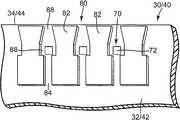
도 4는 도 2의 프린트헤드 조립체의 외부 층의 일부의 일 실시예를 도시하는 개략 사시도,4 is a schematic perspective view illustrating one embodiment of a portion of an outer layer of the printhead assembly of FIG. 2;
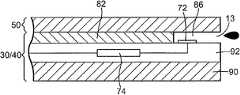
도 5는 도 2의 프린트헤드 조립체의 일부의 일 실시예를 도시하는 개략 단면도,5 is a schematic cross-sectional view showing one embodiment of a portion of the printhead assembly of FIG. 2;
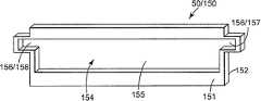
도 6은 도 2의 프린트헤드 조립체의 내부 층의 일 실시예를 도시하는 개략 평면도,6 is a schematic top view illustrating one embodiment of an inner layer of the printhead assembly of FIG. 2;
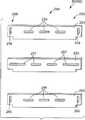
도 7은 도 2의 프린트헤드 조립체의 내부 층의 다른 실시예를 도시하는 개략 평면도,7 is a schematic plan view showing another embodiment of an inner layer of the printhead assembly of FIG. 2;
도 8은 열 전도 경로를 포함하는 프린트헤드 조립체의 박막 구조체 및 기판의 일 실시예를 도시하는 개략 사시도,8 is a schematic perspective view illustrating one embodiment of a substrate and a thin film structure of a printhead assembly including a thermal conduction path;
도 9a, 도 9b 및 도 9c는 도 8의 박막 구조체를 형성하는 일 실시예를 도시하는 개략 사시도,9A, 9B and 9C are schematic perspective views illustrating one embodiment of forming the thin film structure of FIG. 8;
도 10은 프린트헤드 조립체를 위한 열 전도 경로의 일 실시예를 도시하는 개략 사시도.10 is a schematic perspective view illustrating one embodiment of a heat conduction path for a printhead assembly.
이하의 발명의 상세한 설명에 있어서, 본 명세서의 일부를 형성하는 첨부된 도면을 참조하며, 도면에는 본 발명이 실시될 수 있는 구체적인 실시예가 예시적으로 도시된다. 이와 관련하여, "최정상부(top)", "바닥", "전방", "후방", "선두", "후미" 등과 같은 방향 용어는 설명되는 도면의 방위를 참조하여 사용된다. 본 발명의 실시예의 구성요소는 다수의 상이한 배향으로 위치될 수 있기 때문에, 방향 용어는 예시의 목적으로서 사용되고 제한적인 것은 아니다. 다른 실시예가 이용될 수 있고, 구성상 또는 논리적 변경이 본 발명의 범위를 일탈함이 없이 행해질 수 있음을 이해하여야 한다. 따라서, 다음의 상세한 설명은 제한적인 목적으로 취해진 것이 아니고, 본 발명의 범위는 첨부된 청구범위에 의해 규정된다.DETAILED DESCRIPTION In the following detailed description, reference is made to the accompanying drawings that form a part hereof, and in which is shown by way of illustration specific embodiments in which the invention may be practiced. In this regard, directional terms such as "top", "bottom", "front", "rear", "head", "rear", and the like are used with reference to the orientation of the drawings to be described. Since components of embodiments of the present invention may be located in a number of different orientations, directional terms are used for illustrative purposes and are not limiting. It is to be understood that other embodiments may be utilized and structural or logical changes may be made without departing from the scope of the present invention. The following detailed description, therefore, is not to be taken in a limiting sense, and the scope of the present invention is defined by the appended claims.
도 1은 본 발명에 따른 잉크젯 프린팅 시스템(10)의 일 실시예를 도시한다. 잉크젯 프린팅 시스템(10)은 프린트헤드 조립체(12)와 같은 유체 분사 조립체와, 잉크 공급 조립체(14)와 같은 유체 공급 조립체를 포함하는 유체 분사 시스템의 일 실시예를 구성한다. 예시된 실시예에 있어서, 잉크젯 프린팅 시스템(10)은 또한 장착 조립체(16), 매체 이송 조립체(18) 및 전자 제어기(20)를 포함한다.1 shows one embodiment of an
유체 분사 조립체의 일 실시예로서, 프린트헤드 조립체(12)는 본 발명의 실시예에 따라 형성되고, 복수의 오리피스 또는 노즐(13)을 통해 하나 이상의 칼라의 잉크를 포함하는 잉크 액적을 분사한다. 이하의 설명은 프린트헤드 조립체(12)로부터의 잉크의 분사를 언급하지만, 맑은 유체를 포함하는 다른 액체, 유체 또는 유동가능한 재료가 프린트헤드 조립체(12)로부터 분사될 수 있음을 이해하여야 한다.As one embodiment of the fluid ejection assembly, the
일 실시예에 있어서, 프린트 매체(19) 상으로 인쇄하기 위해, 액적은 프린트 매체(19)와 같은 매체를 향해 지향된다. 전형적으로, 노즐(13)은 하나 이상의 칼럼(column) 또는 어레이(arrary)로 배치되어, 일 실시예에 있어서, 프린트헤드 조립체(12) 및 프린트 매체(19)가 서로에 대해 이동됨에 따라, 노즐(13)로부터의 잉크의 적당하게 순서가 정해진 분사는 문자, 기호 및/또는 다른 그래픽 또는 이미지가 프린트 매체(19) 상에 인쇄되도록 한다.In one embodiment, to print onto the
프린트 매체(19)는 종이, 카드 스톡(card stock), 봉투, 라벨, 투명 필름, 판지, 강성 패널 등과 같은 임의의 타입의 적당한 시트(sheet) 재료를 포함한다. 일 실시예에 있어서, 프린트 매체(19)는 연속적인 형태 또는 연속적인 웨브(web) 프린트 매체(19)이다. 그것으로서, 프린트 매체(19)는 미인쇄된 종이의 연속적인 롤을 포함할 수 있다.
유체 공급 조립체의 일 실시예로서, 잉크 공급 조립체(14)는 프린트헤드 조립체(12)에 잉크를 공급하고, 잉크를 저장하기 위한 용기(15)를 포함한다. 그것으로서, 잉크는 용기(15)로부터 프린트헤드 조립체(12)로 유동한다. 일 실시예에 있어서, 잉크 공급 조립체(14) 및 프린트헤드 조립체(12)는 순환 잉크 송출 시스템을 형성한다. 그것으로서, 잉크는 프린트헤드 조립체(12)로부터 용기(15)로 유동하여 복귀한다. 일 실시예에 있어서, 프린트헤드 조립체(12) 및 잉크 공급 조립체(14)는 잉크젯 또는 유체젯(fluidjet) 카트리지 또는 펜(pen) 내에 함께 수용된다. 다른 실시예에 있어서, 잉크 공급 조립체(14)는 프린트헤드 조립체(12)로부터 분리되고, 공급 튜브와 같은 인터페이스 접속부를 통해 프린트헤드 조립체(12)에 잉크를 공급한다.As one embodiment of the fluid supply assembly, the
장착 조립체(16)는 매체 이송 조립체(18)에 대해 프린트헤드 조립체(12)를 위치설정하고, 매체 이송 조립체(18)는 프리트헤드 조립체(12)에 대해 프린트 매체(19)를 위치설정한다. 그것으로서, 프린트헤드 조립체(12)가 그 내에서 잉크 액적을 부착하는 프린트 영역(17)은 프린트헤드 조립체(12) 및 프린트 매체(19) 사이의 영역에 노즐(13)에 인접하여 형성된다. 프린트 매체(19)는 프린팅 동안 매체 이송 조립체(18)에 의해 프린트 영역(17)을 통해 전진한다.The
일 실시예에 있어서, 프린트헤드 조립체(12)는 스캐닝(scanning) 형식 프린트헤드 조립체이고, 장착 조립체(16)는 프린트 매체(19) 상에 줄(swath)의 프린팅 동안 매체 이송 조립체(18) 및 프린트 매체(19)에 대해 프린트헤드 조립체(12)를 이동시킨다. 다른 실시예에 있어서, 프린트헤드 조립체(12)는 비스캐닝 형식 프린트헤드 조립체이고, 장착 조립체(16)는 매체 이송 조립체(18)가 규정된 위치를 지나 프린트 매체(19)를 전진시킴에 따라 프린트 매체(19) 상에의 줄의 프린팅 동안 매체 이송 조립체(18)에 대해 규정된 위치에 프린트헤드 조립체(12)를 고정한다.In one embodiment, the
전자 제어기(20)는 프린트헤드 조립체(12), 장착 조립체(16) 및 매체 이송 조립체(18)와 연통한다. 전자 제어기(20)는 컴퓨터와 같은 호스트 시스템(host system)으로부터 데이터(21)를 수신하고, 데이터(21)를 일시적으로 저장하기 위한 메모리를 포함한다. 전형적으로, 데이터(21)는 전자, 적외선, 광학 또는 다른 데이터 또는 무선 데이터 전송 경로를 따라 잉크젯 프린팅 시스템(10)으로 보내진다. 데이터(21)는 예를 들어 인쇄되어야 할 서류 및/또는 파일을 의미한다. 그것으로서, 데이터(21)는 잉크젯 프린팅 시스템(10)에 대한 프린트 작업을 형성하고, 하나 이상의 프린트 작업 명령 및/또는 명령 파라미터(parameter)를 포함한다.
일 실시예에 있어서, 전자 제어기(20)는 노즐(13)로부터의 잉크 액적의 분사를 위한 타이밍 제어를 포함하는 프린트헤드 조립체(12)의 제어를 제공한다. 그것으로서, 전자 제어기(20)는 프린트 매체(19) 상에 문자, 기호 및/또는 다른 그래픽 또는 이미지를 형성하는 분사된 잉크 액적의 패턴을 규정한다. 타이밍 제어 및 따라서 분사된 잉크 액적의 패턴은 프린트 작업 명령 및/또는 명령 파라미터에 의해 결정된다. 일 실시예에 있어서, 전자 제어기(20)의 일부를 형성하는 논리 및 구동 회로가 프린트헤드 조립체(12) 상에 위치된다. 다른 실시예에 있어서, 논리 및 구동 회로가 프린트헤드 조립체(12)를 벗어나 위치된다.In one embodiment, the
도 2는 프린트헤드 조립체(12)의 일부의 일 실시예를 도시한다. 일 실시예에 있어서, 프린트헤드 조립체(12)는 복수 층 조립체이고, 외부 층(30, 40) 및 적어도 하나의 내부 층(50)을 포함한다. 외부 층(30, 40)은 각각 면 또는 측부(side)(32, 42)와, 각각의 측부(32, 42)와 각각 접촉하는 에지(34, 44)를 구비한다. 외부 층(30, 40)은 내부 층(50)의 대향 측 상에 위치되어, 측부(32, 42)는 내부 층(50)에 면하고 내부 층(50)에 인접한다. 그것으로서, 내부 층(50) 및 외부 층(30, 40)은 축(29)을 따라 적층된다.2 illustrates one embodiment of a portion of a
도 2의 일 실시예에 도시된 바와 같이, 내부 층(50) 및 외부 층(30, 40)은 하나 이상의 노즐(13)의 열(60)을 형성하도록 배치된다. 노즐(13)의 열(60)은 예를 들어 축(29)에 실질적으로 수직한 방향으로 연장한다. 그것으로, 일 실시예에 있어서, 축(29)은 프린트 축 또는 프린트헤드 조립체(12)와 프린트 매체(19) 사이의 상대 운동의 축을 의미한다. 따라서, 노즐(13)의 열(60)의 길이는 프린트헤드 조립체(12)에 의해 프린트 매체(19) 상에 프린트된 줄(swath)의 줄 높이를 수립한다. 예시적인 일 실시예에 있어서, 노즐(13)의 열(60)은 대략 2인치 이하의 거리에 걸친다. 다른 예시적인 실시예에 있어서, 노즐(13)의 열(60)은 대략 2인치 이상의 거리에 걸친다.As shown in one embodiment of FIG. 2, the
예시적인 일 실시예에 있어서, 내부 층(50) 및 외부 층(30, 40)은 노즐(13)의 2개의 열(61, 62)을 형성한다. 보다 구체적으로, 내부 층(50) 및 외부 층(30)은 외부 층(30)의 에지(34)를 따라 노즐(13)의 열(61)을 형성하고, 내부 층(50) 및 외부 층(40)은 외부 층(40)의 에지(44)를 따라 노즐(13)의 열(62)을 형성한다. 그것으로서, 일 실시예에 있어서, 노즐(13)의 열(61, 62)은 서로로부터 이격되고 서로에 대해 실질적으로 평행하게 배향된다.In one exemplary embodiment, the
일 실시예에 있어서, 도 2에 도시된 바와 같이, 열(61, 62)의 노즐(13)은 실질적으로 정렬된다. 보다 구체적으로, 열(61)의 각 노즐(13)은 축(29)에 실질적으로 평행하게 배향된 프린트 라인을 따라 열(62)의 하나의 노즐(13)과 실질적으로 정렬된다. 그것으로서, 유체(또는 잉크)는 주어진 프린트 라인을 따라 복수의 노즐을 통해 분사될 수 있기 때문에, 도 2의 실시예는 노즐 잉여(redundancy)를 제공한다. 따라서, 결함있는 또는 비작동성 노즐은 다른 정렬된 노즐에 의해 보상될 수 있다. 추가하여, 노즐 잉여는 정렬된 노즐 사이에 노즐 작동을 교대시키는 능력을 제공한다.In one embodiment, as shown in FIG. 2, the
도 3은 프린트헤드 조립체(12)의 일부의 다른 실시예를 도시한다. 프린트헤드 조립체(12)와 유사하게, 프린트헤드 조립체(12')는 복수 층 조립체이고, 외부 층(30', 40') 및 내부 층(50)을 포함한다. 추가하여, 외부 층(30, 40)에 유사하게, 외부 층(30', 40')은 내부 층(50)의 대향 측 상에 위치된다. 그러한 것으로서, 내부 층(50) 및 외부 층(30', 40')은 노즐(13)의 2개의 열(61', 62')을 형성한다.3 illustrates another embodiment of a portion of a
도 3의 실시예에 도시된 바와 같이, 열(61', 62')의 노즐은 오프셋(offset)된다. 보다 구체적으로, 열(61')의 각 노즐(13)은 축(29)에 실질적으로 평행하게 배향된 프린트 라인을 따라 열(62')의 하나의 노즐(13)로부터 엇갈리거나 또는 오프셋된다. 그러한 것으로서, 축(29)에 실질적으로 수직하게 배향된 라인을 따라 프린트될 수 있는 인치 당 도트(dot per inch)(dpi)의 수가 증가되기 때문에, 도 3의 실시예는 증가된 해상도를 제공한다.As shown in the embodiment of FIG. 3, the nozzles in
일 실시예에 있어서, 도 4에 도시된 바와 같이, 외부 층(30, 40)[오직 하나만이 도 4에 도시되고, 외부 층(30', 40')을 포함함] 각각은 측부(32, 42) 상에 각각 형성된 액적 분사 요소(70) 및 유체 경로(80)를 포함한다. 액적 분사 요소(70) 및 유체 경로(80)는, 유체 경로(80)가 액적 분사 요소(70)와 연통하여 유체(또는 잉크)를 공급하도록, 배치된다. 일 실시예에 있어서, 액적 분사 요소(70) 및 유체 경로(80)는 각 외부 층(30, 40)의 측부(32, 42) 상에 실질적으로 선형의 어레이(array)로 배치된다. 그러한 것으로서, 외부 층(30)의 모든 액적 분사 요소(70) 및 유체 경로(80)는 단일 또는 모놀리식(monolithic) 층 상에 형성되고, 외부 층(40)의 모든 액적 분사 요소(70) 및 유체 경로(80)는 단일 또는 모놀리식 층 상에 형성된다.In one embodiment, as shown in FIG. 4, each of the
일 실시예에 있어서, 이하에 설명되는 바와 같이, 내부 층(50)(도 2)은 내부에 형성된 유체 매니폴드 또는 유체 경로를 구비하고, 유체 매니폴드 또는 유체 경로는 예를 들어 잉크 공급 조립체(14)에 의해 공급된 유체를 외부 층(30, 40) 상에 형성된 유체 경로(80) 및 액적 분사 요소(70)에 분배한다.In one embodiment, as described below, the inner layer 50 (FIG. 2) has a fluid manifold or fluid path formed therein, and the fluid manifold or fluid path is for example an ink supply assembly ( The fluid supplied by 14 is distributed to the
일 실시예에 있어서, 유체 경로(80)는 각 외부 층(30, 40)의 측부(32, 42) 상에 형성된 배리어(barrier)(82)의해 규정된다. 그러한 것으로서, 외부 층(30, 40)이 내부 층(50)의 대향 측 상에 위치될 때, 내부 층(50)(도 2) 및 외부 층(30)의 유체 경로(80)는 에지(34)를 따라 노즐(13)의 열(61)을 형성하고, 내부 층(50)(도 2) 및 외부 층(40)의 유체 경로(80)는 에지(44)를 따라 노즐(13)의 열(62)을 형성한다.In one embodiment, the
도 4의 실시예에 도시된 바와 같이, 각 유체 경로(80)는 유체 입구(84), 유체 챔버(86) 및 유체 출구(88)를 포함하여, 유체 챔버(86)는 유체 입구(84) 및 유체 출구(88)와 연통한다. 유체 입구(84)는 이하에 설명되는 바와 같이 유체(또는 잉크)의 공급부와 연통하고, 유체 챔버(86)에 유체(또는 잉크)를 공급한다. 외부 층(30, 40)이 내부 층(50)의 대향 측 상에 위치될 때, 유체 출구(88)는 유체 챔버(86)와 연통하고, 일 실시예에 있어서 각 노즐(13)의 일부를 형성한다.As shown in the embodiment of FIG. 4, each
일 실시예에 있어서, 각 액적 분사 요소(70)는 각 유체 경로(80)의 유체 챔버(86) 내에 형성된 발사 레지스터(firing resistor)(72)를 포함한다. 발사 레지스터(72)는 예를 들어, 전압이 가해졌을 때, 유체 챔버(86) 내의 유체를 가열하여 유체 챔버(86) 내에 버블(bubble)을 생성하고 노즐(13)을 통해 분사되는 유체의 비말(飛沫)을 발생시키는 히터(heater) 레지스터를 포함한다. 그러한 것으로서, 일 실시예에 있어서, 각 유체 챔버(86), 발사 레지스터(72) 및 노즐(13)은 각 액적 분사 요소(70)의 액적 발생기를 형성한다.In one embodiment, each
일 실시예에 있어서, 작동 동안 유체는 유체 입구(84)로부터, 각 발사 레지스터(72)의 작동시 유체 출구(88) 및 각 노즐(13)을 통해 유체 챔버(86)로부터 유체의 비말이 분사되는 유체 챔버(86)로 유동한다. 그러한 것으로서, 유체의 비말은 매체를 향하여 각 외부 층(30, 40)의 측부(32, 42)에 실질적으로 평행하게 분사된다. 따라서, 일 실시예에 있어서, 프린트헤드 조립체(12)는 사이드-슈터(side-shooter) 디자인을 구성한다.In one embodiment, fluid is sprayed from the
일 실시예에 있어서, 도 5에 도시된 바와 같이, 외부 층(30, 40)[오직 하나만이 도 5에 도시되고, 외부 층(30', 40')을 포함함] 각각은 기판(90)과 기판(90) 상에 형성된 박막 구조체(92)를 포함한다. 그러한 것으로서, 액적 분사 요소(70)의 발사 레지스터(72) 및 유체 경로(80)의 배리어(82)가 박막 구조체(92) 상에 형성된다. 상술된 바와 같이, 외부 층(30, 40)은 내부 층(50)의 대향 측 상에 위치되어, 각 액적 분사 요소(70)의 유체 챔버(86) 및 노즐(13)을 형성한다.In one embodiment, as shown in FIG. 5, each of the
일 실시예에 있어서, 내부 층(50) 및 외부 층(30, 40)의 기판(90)은 각각 공통의 재료를 포함한다. 그러한 것으로서, 내부 층(50)과 외부 층(30, 40)의 열팽창 계수는 실질적으로 정합된다. 따라서, 내부 층(50) 및 외부 층(30, 40) 사이의 열구배는 최소화된다. 내부 층(50) 및 외부 층(30, 40)의 기판(90)에 적당한 예시적인 재료는 유리, 금속, 세라믹 재료, 탄소 복합 재료, 금속 매트릭스 복합 재료 또는 화학적으로 비활성이고 열적으로 안정한 임의의 재료를 포함한다.In one embodiment, the
예시적인 일 실시예에 있어서, 내부 층(50) 및 외부 층(30, 40)의 기판(90)은 상표명 코닝 1737(Corning® 1737) 유리 또는 상표명 코닝 1740(Corning® 1740) 유리와 같은 유리를 포함한다. 예시적인 일 실시예에 있어서, 내부 층(50) 및 외부 층(30, 40)의 기판(90)이 금속 또는 금속 메트릭스 복합 재료를 포함할 때, 산화 층이 기판(90)의 금속 또는 금속 메트릭스 복합 재료 상에 형성된다.In one illustrative embodiment, the
일 실시예에 있어서, 박막 구조체(92)는 액적 분사 요소(70)를 위한 구동 회로(74)를 포함한다. 구동 회로(74)는 예를 들어 보다 구체적으로 발사 레지스터(72)를 포함하는 액적 분사 요소(70)에 전원, 접지 및 논리를 제공한다.In one embodiment, the
일 실시예에 있어서, 박막 필름 구조체(92)는 예를 들어 이산화 실리콘, 탄화 실리콘, 질화 실리콘, 탄탈, 폴리 실리콘 유리 또는 다른 적당한 재료로 형성된 하나 이상의 패시베이션(passivation) 또는 절연 층을 포함한다. 추가하여, 박막 필름 구조체(92)는 예를 들어 알루미늄, 금, 탄탈, 탄탈 알루미늄 또는 다른 금속 또는 금속 합금에 의해 형성된 하나 이상의 전도 층을 포함한다. 일 실시예에 있어서, 박막 구조체(92)는 액적 분사 요소(70)를 위한 구동 회로(74)의 일부를 형성하는 박막 트랜지스터를 포함한다.In one embodiment, the
도 5의 실시예에 도시된 바와 같이, 유체 경로(80)의 배리어(82)는 박막 구조체(92) 상에 형성된다. 일 실시예에 있어서, 배리어(82)는 프린트헤드 조립체(12)를 통해 발송되고 그리고 프린트헤드 조립체(12)로부터 분사될 유체(또는 잉크)와 조화되는 비전도성 재료로 형성된다. 배리어(82)에 적당한 예시적인 재료는 포토-이미지어블(photo-imageable) 폴리머 및 유리를 포함한다. 포토-이미지어블 폴리머는 SU8과 같은 스펀-온(spun-on) 재료 또는 상표명 듀폰 바크렐(DuPont Vacrel®)과 같은 건식 필름(dry-film) 재료를 포함할 수 있다.As shown in the embodiment of FIG. 5, a
도 5의 실시예에 도시된 바와 같이, 외부 층(30, 40)[외부 층(30', 40')을 포함]은 배리어(82)에서 내부 층(50)에 접합된다. 일 실시예에 있어서, 배리어(82)가 포토-이미지어블 폴리머 또는 유리로 형성되면, 외부 층(30, 40)은 온도 및 압력에 의해 내부 층(50)에 접착된다. 하지만, 다른 적당한 접합 또는 접착 기술이 또한 외부 층(30, 40)을 내부 층(50)에 접합시키는 데에 사용될 수 있다.As shown in the embodiment of FIG. 5,
도 6에 도시된 바와 같이, 일 실시예에 있어서, 내부 층(50)은 단일 내부 층(150)을 포함한다. 단일 내부 층(150)은 제 1 측부(151), 및 제 1 측부(151)와 대향하는 제 2 측부(152)를 갖는다. 일 실시예에 있어서, 외부 층(30, 40)이 내부 층(50)의 대향 측부 상에 위치될 때, 외부 층(30)의 측부(32)(도 4)는 제 1 측부(151)와 인접하고, 외부 층(40)의 측부(42)는 제 2 측부(152)와 인접한다.As shown in FIG. 6, in one embodiment, the
일 실시예에 있어서, 단일 내부 층(150)은 내부에 형성된 유체 통로(154)를 갖는다. 유체 통로(154)는 예를 들어 단일 내부 층(150)의 제 1 측부(151) 및 제 2 측부(152)와 연통하고, 단일 내부 층(150)의 대향 단부 사이로 연장하는 개구(155)를 포함한다. 그러한 것으로서, 외부 층(30, 40)이 단일 내부 층(150)의 대향 측 상에 위치될 때, 유체 통로(154)는 단일 내부 층(150)을 통해 외부 층(30, 40)의 유체 경로(80)에 유체를 분배한다.In one embodiment, the single inner layer 150 has a
도 6의 실시예에 도시된 바와 같이, 단일 내부 층(150)은 적어도 하나의 유체 포트(156)를 포함한다. 예시적인 일 실시예에 있어서, 단일 내부 층(150)은 각각 유체 통로(154)와 연통하는 유체 포트(157, 158)를 포함한다. 일 실시예에 있어서, 유체 포트(157, 158)는 유체 통로(154)를 위한 유체 입구 및 유체 출구를 형성한다. 그러한 것으로서, 유체 포트(157, 158)는 잉크 공급 조립체(14)(도 1)와 연통하고, 잉크 공급 조립체(14)와 프린트헤드 조립체(12) 사이의 유체(또는 잉크)의 순환을 가능하게 한다.As shown in the embodiment of FIG. 6, the single inner layer 150 includes at least one fluid port 156. In one exemplary embodiment, the single inner layer 150 includes fluid ports 157 and 158 in communication with the
다른 실시예에 있어서, 도 7에 도시된 바와 같이, 내부 층(150)은 복수의 내부 층(250)을 포함한다. 예시적인 일 실시예에 있어서, 내부 층(250)은 내부 층(251, 252, 253)을 포함하고, 내부 층(253)은 내부 층(251, 252) 사이에 개재된다. 그러한 것으로서, 외부 층(30, 40)이 내부 층(250)의 대향 측 상에 위치될 때, 외부 층(30)의 측부(32)는 내부부 층(152)과 인접하고, 외부 층(40)의 측부(42)는 내부 층(252)과 인접한다.In another embodiment, as shown in FIG. 7, the inner layer 150 includes a plurality of inner layers 250. In one exemplary embodiment, inner layer 250 includes
예시적인 일 실시예에 있어서, 내부 층(251, 252, 253)은 유리 프릿(glass frit) 접합에 의해 함께 접합된다. 그러한 것으로서, 유리 프릿 재료는 내부 층(251, 252 및/또는 253) 상에 퇴적되고 패턴화되며, 내부 층(251, 252, 253)은 온도 및 압력 하에서 함께 접합된다. 따라서, 내부 층(251, 252, 253) 사이의 접합은 열적으로 정합된다. 다른 예시적인 실시예에 있어서, 내부 층(251, 252, 253)은 양극 접합(anodic bonding)에 의해 함께 접합된다. 그러한 것으로서, 내부 층(251, 252, 253)은 상호 접촉하게 되고, 전압이 층을 횡단하여 가해진다. 따라서, 추가 재료가 사용되지 않기 때문에, 내부 층(251, 252, 253) 사이의 접합은 열적으로 정합되고, 화학적으로 비활성이다. 다른 예시적인 실시예에 있어서, 내부 층(251, 252, 253)은 접착제 접합에 의해 함께 접합된다. 하지만, 다른 적당한 접합 또는 접착 기술이 내부 층(251, 252, 253)을 접합하는 데에 사용될 수 있다.In one exemplary embodiment, the
일 실시예에 있어서, 내부 층(250)은 내부에 형성된 유체 매니폴드 또는 유체 통로(254)를 갖는다. 유체 통로(254)는 예를 들어 내부 층(251)에 형성된 개구(255), 내부 층(252)에 형성된 개구(256) 및 내부 층(253)에 형성된 개구(257)를 포함한다. 내부 층(253)이 내부 층(251, 252) 사이에 개재될 때, 내부 층(253)의 개구(257)가 내부 층(251, 252)의 개구(255, 256)와 각각 연통하도록, 개구(255, 256, 257)가 형성되고 배치된다. 그러한 것으로서, 외부 층(30, 40)이 내부 층(250)의 대향 측 상에 위치될 때, 유체 통로(254)는 내부 층(250)을 통해 그리고 외부 층(30, 40)의 유체 경로(80)로 유체를 분배한다.In one embodiment, the inner layer 250 has a fluid manifold or
도 7의 실시예에 도시된 바와 같이, 내부 층(250)은 적어도 하나의 유체 포트(258)를 포함한다. 예시적인 일 실시예에 있어서, 내부 층(250)은 각각 내부 층(251, 252)에 형성된 유체 포트(259, 260)를 포함한다. 그러한 것으로서, 내부 층(253)이 내부 층(251, 252) 사이에 개재될 때, 유체 포트(259, 260)는 내부 층(253)의 개구(257)와 연통한다. 일 실시예에 있어서, 유체 포트(259, 260)는 유체 통로(254)를 위한 유체 입구 및 유체 출구를 형성한다. 그러한 것으로서, 유체 포트(259, 260)는 잉크 공급 조립체(14)와 연통하고, 잉크 공급 조립체(14) 및 프린트헤드 조립체(12) 사이의 유체(또는 잉크)의 순환을 가능하게 한다.As shown in the embodiment of FIG. 7, inner layer 250 includes at least one
일 실시예에 있어서, 상술된 바와 같이, 외부 층(30, 40) 상에 액적 분사 요소(70) 및 유체 경로(80)를 형성하고, 외부 층(30, 40)을 내부 층(50)의 대향 측 상에 위치시킴으로써, 프린트헤드 조립체(12)가 여러 길이로 형성될 수 있다. 예를 들어, 프린트헤드 조립체(12)는 공칭 페이지 폭, 또는 공칭 페이지 폭보다 짧거나 긴 폭에 걸칠 수 있다. 예시적인 일 실시예에 있어서, 프린트헤드 조립체(12)는 와이드-어레이(wide-array) 또는 페이지-와이드(page-wide)로서 형성되어, 노즐(13)의 열(61, 62)은 공칭 페이지 폭에 걸친다.In one embodiment, as described above, the
일 실시예에 있어서, 도 5를 참조하여 상술된 바와 같이, 외부 층(30, 40)은 기판(90) 및 기판(90) 상에 형성된 박막 구조체(92)를 각각 포함한다. 그러한 것으로서, 액적 분사 요소(70)의 발사 레지스터(72) 및 유체 경로(80)의 배리어(82)는 박막 구조체(92) 상에 형성된다.In one embodiment, as described above with reference to FIG. 5, the
일 실시예에 있어서, 도 8에 도시된 바와 같이, 기판(90)은 기판(190)을 포함하고, 박막 구조체(92)는 박막 구조체(192)를 포함한다. 일 실시예에 있어서, 기판(90)과 유사하게, 기판(190)은 유리, 금속, 세라믹 재료, 탄소 복합 재료, 금속 메트릭스 복합 재료, 또는 화학적으로 비활성이고 열적으로 안정한 다른 임의의 재료로 형성된다. 일 실시예에 있어서, 이하에 설명되는 바와 같이, 열 전도 경로는 발사 레지스터(72)에 의해 발생된 열을 배리어(832)(도 4)에 전달하기 위해 박막 구조체(192) 내에 형성된다.In one embodiment, as shown in FIG. 8, the
도 8의 실시예에 도시된 바와 같이, 박막 구조체(192)는 전기 전도성 층(1921) 및 절연성 층(1922)를 포함한다. 전기 전도성 층(1921)은 기판(190)의 측 상에 제공되고, 발사 레지스터(72)를 위한 전원 층 또는 전원 평면을 형성한다. 절연성 층(1922)은 전기 전도성 층(1921) 위에 형성되고, 전기 전도성 층(1921) 및 트레이스 라우팅(trace routing)(74)과 발사 레지스터(72)와 같은 박막 구조체(192)의 전기 전도성 재료 사이의 전기적 단락을 방지한다.As shown in the embodiment of FIG. 8, the
일 실시예에 있어서, 도 8에 도시된 바와 같이, 서멀 비아(thermal via)(194)(오직 하나만이 도 8에 도시됨)가 절연성 층(1922)을 통해 전기 전도성 층(1921)으로 형성된다. 추가하여, 열 패드(thermal pad)(194)가 절연성 층(1922) 상에 그리고 서멀 비아(194) 위에 형성된다. 그러한 것으로서, 열 패드(196)는 서멀 비아(194)와 접촉 및 연통하고, 서멀 비아는 차례로 절연성 층(1922)을 통해 전기 전도성 층(1921)과 접촉 및 연통한다. 일 실시예에 있어서, 서멀 비아(194) 및 열 패드(196)는 이하에 설명하는 바와 같이 열 전도 경로의 일부를 형성한다.In one embodiment, as shown in FIG. 8, a thermal via 194 (only one shown in FIG. 8) is formed into the electrically
도 9a, 도 9b 및 도 9c는 서멀 비아(194) 및 열 패드(196)를 포함하여 외부 층(30 및/또는 40)을 형성하는 일 실시예를 도시한다. 도 9a에 도시된 바와 같이, 전기 전도성 층(1921)은 기판(190)의 측 상에 형성되고, 절연성 층(1922)은 전기 전도성 층(1921) 위에 형성된다. 추가하여, 서멀 비아(194)(도 8)를 형성하기 위한 구멍(1923) 및 박막 구조체(192)의 전기적 비아(도시되지 않음)를 형성하기 위한 구멍(1924)이 절연성 층(1922)에 형성된다. 일 실시예에 있어서, 구멍(1923, 1924)은 절연성 층(1922)을 통해 전기 전도성 층(1921)으로 연장한다. 또한, 일 실시예에 있어서, 전기 전도성 층(1921)이 베이스 층 위에 형성된 상태에서, 예를 들어 폴리실리콘으로 형성된 베이스 층이 먼저 기판(190)의 측 상에 형성된다.9A, 9B, and 9C illustrate one embodiment of forming
일 실시예에 있어서, 전기 전도성 층(1921)은 예를 들어 알루미늄과 같은 전기 전도성 재료로 형성된다. 추가하여, 절연성 층은 예를 들어 이산화 실리콘, 탄화 실리콘, 질화 실리콘 또는 다른 적당한 재료와 같은 절연성 재료로 형성된다. 서멀 비아(194) 및 전기적 비아(도시되지 않음)를 위한 구멍(1923, 1924)은 예를 들어 포토리소그라피(photolithography) 기술을 이용하여 절연성 층(1922)에 형성된다.In one embodiment, the electrically
도 9b에 도시된 바와 같이, 서멀 비아(194)는 절연성 층(1922)의 구멍(1923) 내에 형성되고, 열 패드(196)는 절연성 층(1922) 상에 그리고 서멀 비아(194) 위에 형성된다. 추가하여, 액적 분사 요소(70)의 발사 레지스터(72)는 절연성 층(1922) 상에 형성되고, 발사 레지스터(72)를 위한 트레이스 라우팅(74)은 절연성 층(1922) 상에 형성된다. 또한, 전기적 비아(도시되지 않음)는 절연성 층(1922)의 구멍(1924) 내에 형성된다.As shown in FIG. 9B,
따라서, 도 9b의 실시예에 있어서, 서멀 비아(194)는 전기 전도성 층(1921)과 접촉 및 연통하고, 열 패드(196)와 접촉 및 연통한다. 추가하여, 전기적 비아는 절연성 층(1922)을 통해 전기 전도성 층(1921)과 접촉 및 연통하고, 트레이스 라우팅(74)과 접촉 및 연통한다. 그러한 것으로서, 서멀 비아(194) 및 열 패드(196)는 전기 전도성 층(1921)으로부터 절연성 층(1922)을 통해 열적 경로를 제공하고, 전기적 비아는 전기 전도성 층(1921)으로부터 트레이스 라우팅(74) 및 발사 레지스터(72)까지의 전기적 경로를 제공한다.Thus, in the embodiment of FIG. 9B, thermal via 194 contacts and communicates with electrically
일 실시예에 있어서, 서멀 비아(194) 및 열 패드(196)는 알루미늄과 같은 열 전도성 재료로 형성된다. 추가하여, 구멍(1924) 내에 형성된 전기적 비아 및 트레이스 라우팅(74)은 알루미늄과 같은 전기 전도성 재료로 형성된다. 더욱, 발사 레지스터(72)는 예를 들어, 알루미늄, 금, 탄탈, 탄탈 알루미늄 또는 다른 금속 또는 금속 합금을 포함하는 하나 이상의 전도성 층으로 형성된다.In one embodiment, thermal via 194 and
도 9c의 실시예에 도시된 바와 같이, 패시베이션 층(1925)은 절연성 층(1922), 열 패드(196), 발사 레지스터(72) 및 트레이스 라우팅(74) 위에 형성된다. 서멀 비아(194)가 전기 전도성 층(1921)과 연통하고, 열 패드(196)가 서멀 비아(194)와 연통하기 때문에, 패시베이션 층(1925)은 트레이스 라우팅(74), 발사 레지스터(72) 및 열 패드(196) 사이의 전기적 단락을 방지한다. 일 실시예에 있어서, 패시베이션 층(1925)은 예를 들어 탄화 실리콘, 질화 실리콘 또는 탄탈과 같은 열적 전도성 재료로 형성된다.As shown in the embodiment of FIG. 9C,
또한, 도 9c의 실시예에 도시된 바와 같이, 배리어(82)는 패시베이션 층(1925) 상에 형성된다. 배리어(82)는 각각의 열 패드(196)(도 9b) 위에 위치되고, 상술된 바와 같이 유체 챔버(86)와 함께 유체 경로(80)를 형성한다. 일 실시예에 있어서, 상술된 바와 같이, 배리어(82)는 포토-이미지어블 폴리머 또는 유리와 같은 열적 전도성 및 전기적 비전도성 재료로 형성되거나, 또는 용착 금속(deposited metal)과 같은 열 및 전기 전도성 재료로 형성된다.In addition, as shown in the embodiment of FIG. 9C, a
일 실시예에 있어서, 도 10에 도시된 바와 같이, 프린트헤드 조립체(12)는 열 전도 경로(198)를 포함한다. 열 전도 경로(198)는 유체 챔버(86) 및 배리어(82) 사이에 형성되고, 유체 챔버(86) 내에서 발사 레지스터(72)에 의해 발생된 열을 배리어(82)의 재료에 전달하기 위한 경로를 제공한다. 일 실시예에 있어서, 열 전도 경로(198)는 박막 구조체(192) 내에 형성된다. 보다 구체적으로, 일 실시예에 있어서, 박막 구조체(192)의 열 패드(196), 서멀 비아(194), 전기 전도성 층(1921)은 이하에 설명되는 바와 같이 열 전도 경로(198)의 부분들을 형성한다.In one embodiment, as shown in FIG. 10,
일 실시예에 있어서, 전기 전도성 층(1921), 절연성 층(1922), 패시베이션 층(1925), 서멀 비아(194), 및 배리어(82)는 열 전도성 재료로 각각 형성된다. 그러한 것으로서, 유체 챔버(86) 내에서 발사 레지스터(72)에 의해 발생된 열은 기판(190)을 향해 절연성 층(1922)을 통해 전기 전도성 층(1921)으로 전파된다. 그 후 열은 전기 전도성 층(1921)으로부터 서멀 비아(194)로 따른다.In one embodiment, electrically
서멀 비아(194)에서, 열은 서멀 비아(194)를 통해 열 패드(196)로 이동한다. 그러한 것으로서, 열 패드(196)는 영역에 걸쳐 열을 퍼뜨린다. 그 후, 열은 패시베이션 층(1925)을 통해 배리어(82)로 전파된다. 배리어(82)에서, 열은 재료 전체에 걸쳐서 방산된다.In thermal via 194, heat travels through thermal via 194 to
일 실시예에 있어서, 배리어(82)가 유체 경로(80)를 형성하고 유체(또는 잉크)가 유체 경로(80)를 통해 유동하는 상태에서, 열은 배리어(82)로부터, 유체 경로(80)를 통해 공급되고 유체 챔버(86)로부터 분사되는 유체(또는 잉크)에 전달된다. 따라서, 열 전도 경로(198)에 의해, 유체 챔버(86) 내에서의 열의 형성(build-up)은 완화된다. 추가하여, 배리어(82)를 예를 들어 도 9c의 실시예에 도시된 바와 같이 개별 특징부 또는 "섬(island)"으로서 형성하는 것에 의해, 배리어(82)로부터 유체 경로(80)를 통해 공급된 유체(또는 잉크)로의 열 전달은 배리어(82)의 3개의 측부를 따라 발생되고, 그에 의해 열 전달을 강화시킬 것이다.In one embodiment, with
비록 특정 실시예가 본 명세서에서 예시되고 설명되었지만, 당업자는 여러 변형 및/또는 균등한 실시가 본 발명의 범위로부터 일탈하지 않고 도시되고 설명된 특정 실시예와 대체될 수 있음을 이해할 것이다. 본 출원은 본 명세서에서 논의된 특정 실시예의 모든 적용 또는 변형을 포괄하도록 의도된다. 따라서, 본 발명은 청구항 및 균등 범위에 의해서만 제한되는 것으로 의도된다.Although specific embodiments have been illustrated and described herein, those skilled in the art will understand that various modifications and / or equivalent implementations may be substituted for the specific embodiments shown and described without departing from the scope of the invention. This application is intended to cover all adaptations or variations of the specific embodiments discussed herein. Therefore, it is intended that this invention be limited only by the claims and the equivalents.
Claims (19)
Translated fromKoreanApplications Claiming Priority (3)
| Application Number | Priority Date | Filing Date | Title |
|---|---|---|---|
| US11/114,980 | 2005-04-26 | ||
| US11/114,980US7380914B2 (en) | 2005-04-26 | 2005-04-26 | Fluid ejection assembly |
| PCT/US2006/013887WO2006115810A1 (en) | 2005-04-26 | 2006-04-13 | Fluid ejection assembly |
Publications (2)
| Publication Number | Publication Date |
|---|---|
| KR20080002869Atrue KR20080002869A (en) | 2008-01-04 |
| KR101257968B1 KR101257968B1 (en) | 2013-04-30 |
Family
ID=36694271
Family Applications (1)
| Application Number | Title | Priority Date | Filing Date |
|---|---|---|---|
| KR1020077024487AExpired - Fee RelatedKR101257968B1 (en) | 2005-04-26 | 2006-04-13 | Fluid ejection assembly |
Country Status (13)
| Country | Link |
|---|---|
| US (2) | US7380914B2 (en) |
| EP (1) | EP1874545B1 (en) |
| KR (1) | KR101257968B1 (en) |
| CN (1) | CN101163592B (en) |
| AT (1) | ATE503633T1 (en) |
| AU (1) | AU2006240304B2 (en) |
| BR (1) | BRPI0612954B1 (en) |
| CA (1) | CA2603702C (en) |
| DE (1) | DE602006020995D1 (en) |
| IL (1) | IL186273A (en) |
| MX (1) | MX2007013232A (en) |
| TW (1) | TWI295972B (en) |
| WO (1) | WO2006115810A1 (en) |
Families Citing this family (4)
| Publication number | Priority date | Publication date | Assignee | Title |
|---|---|---|---|---|
| US20080079779A1 (en)* | 2006-09-28 | 2008-04-03 | Robert Lee Cornell | Method for Improving Thermal Conductivity in Micro-Fluid Ejection Heads |
| WO2010050977A1 (en)* | 2008-10-31 | 2010-05-06 | Hewlett-Packard Development Company, L.P. | Thermal fluid-ejection device die |
| US8444255B2 (en)* | 2011-05-18 | 2013-05-21 | Hewlett-Packard Development Company, L.P. | Power distribution in a thermal ink jet printhead |
| USD961675S1 (en) | 2020-02-18 | 2022-08-23 | Ward-Kraft, Inc. | Combination wristband label form with tags |
Family Cites Families (54)
| Publication number | Priority date | Publication date | Assignee | Title |
|---|---|---|---|---|
| AT372651B (en) | 1980-12-15 | 1983-11-10 | Philips Nv | INK-JET PRINT HEAD AND METHOD FOR PRODUCING SUCH INK-JET PRINT HEAD |
| JPS57102366A (en) | 1980-12-18 | 1982-06-25 | Canon Inc | Ink jet head |
| EP0067653A3 (en) | 1981-06-13 | 1983-11-09 | Konica Corporation | Printing head for ink jet printer |
| US4611219A (en) | 1981-12-29 | 1986-09-09 | Canon Kabushiki Kaisha | Liquid-jetting head |
| US4438191A (en) | 1982-11-23 | 1984-03-20 | Hewlett-Packard Company | Monolithic ink jet print head |
| US4646110A (en) | 1982-12-29 | 1987-02-24 | Canon Kabushiki Kaisha | Liquid injection recording apparatus |
| JPH0624855B2 (en) | 1983-04-20 | 1994-04-06 | キヤノン株式会社 | Liquid jet recording head |
| JPH0613219B2 (en) | 1983-04-30 | 1994-02-23 | キヤノン株式会社 | Inkjet head |
| JPH062416B2 (en) | 1984-01-30 | 1994-01-12 | キヤノン株式会社 | Liquid jet recording head manufacturing method |
| US4680595A (en) | 1985-11-06 | 1987-07-14 | Pitney Bowes Inc. | Impulse ink jet print head and method of making same |
| US4730197A (en) | 1985-11-06 | 1988-03-08 | Pitney Bowes Inc. | Impulse ink jet system |
| US4965594A (en) | 1986-02-28 | 1990-10-23 | Canon Kabushiki Kaisha | Liquid jet recording head with laminated heat resistive layers on a support member |
| US4894664A (en) | 1986-04-28 | 1990-01-16 | Hewlett-Packard Company | Monolithic thermal ink jet printhead with integral nozzle and ink feed |
| US4695854A (en) | 1986-07-30 | 1987-09-22 | Pitney Bowes Inc. | External manifold for ink jet array |
| US4897668A (en) | 1987-03-02 | 1990-01-30 | Kabushiki Kaisha Toshiba | Apparatus for transferring ink from ink ribbon to a recording medium by applying heat to the medium, thereby recording data on the medium |
| US4823149A (en) | 1987-03-09 | 1989-04-18 | Dataproducts Corporation | Ink jet apparatus employing plate-like structure |
| EP0345724B1 (en) | 1988-06-07 | 1995-01-18 | Canon Kabushiki Kaisha | Liquid jet recording head and recording device having the same head |
| US5068674A (en) | 1988-06-07 | 1991-11-26 | Canon Kabushiki Kaisha | Liquid jet recording head stabilization |
| JP2849109B2 (en) | 1989-03-01 | 1999-01-20 | キヤノン株式会社 | Method of manufacturing liquid jet recording head and liquid jet recording head manufactured by the method |
| NL8903025A (en) | 1989-12-08 | 1991-07-01 | Oce Nederland Bv | STACKABLE DROP GENERATOR FOR AN INK-JET PRINTER. |
| US5469199A (en) | 1990-08-16 | 1995-11-21 | Hewlett-Packard Company | Wide inkjet printhead |
| US5132707A (en) | 1990-12-24 | 1992-07-21 | Xerox Corporation | Ink jet printhead |
| US5604519A (en) | 1992-04-02 | 1997-02-18 | Hewlett-Packard Company | Inkjet printhead architecture for high frequency operation |
| US5825382A (en) | 1992-07-31 | 1998-10-20 | Francotyp-Postalia Ag & Co. | Edge-shooter ink jet print head and method for its manufacture |
| DE4225799A1 (en) | 1992-07-31 | 1994-02-03 | Francotyp Postalia Gmbh | Inkjet printhead and process for its manufacture |
| US5622897A (en) | 1993-05-20 | 1997-04-22 | Compaq Computer Corporation | Process of manufacturing a drop-on-demand ink jet printhead having thermoelectric temperature control means |
| JP3143549B2 (en) | 1993-09-08 | 2001-03-07 | キヤノン株式会社 | Substrate for thermal recording head, inkjet recording head using the substrate, inkjet cartridge, inkjet recording apparatus, and method of driving recording head |
| DE4336416A1 (en) | 1993-10-19 | 1995-08-24 | Francotyp Postalia Gmbh | Face shooter ink jet printhead and process for its manufacture |
| JPH07137270A (en) | 1993-11-16 | 1995-05-30 | Canon Inc | Inkjet recording device |
| US5880756A (en) | 1993-12-28 | 1999-03-09 | Seiko Epson Corporation | Ink jet recording head |
| US5565900A (en) | 1994-02-04 | 1996-10-15 | Hewlett-Packard Company | Unit print head assembly for ink-jet printing |
| DE4424771C1 (en) | 1994-07-05 | 1995-11-23 | Francotyp Postalia Gmbh | Ink printhead made up of individual ink printing modules |
| EP0695641B1 (en) | 1994-08-03 | 2001-04-04 | Francotyp-Postalia Aktiengesellschaft & Co. | Arrangement for plate-like piezoelectric actuators and method of manufacturing |
| US5748214A (en) | 1994-08-04 | 1998-05-05 | Seiko Epson Corporation | Ink jet recording head |
| JP3196811B2 (en) | 1994-10-17 | 2001-08-06 | セイコーエプソン株式会社 | Laminated ink jet recording head and method of manufacturing the same |
| US5699094A (en)* | 1995-08-11 | 1997-12-16 | Xerox Corporation | Ink jet printing device |
| US6135586A (en) | 1995-10-31 | 2000-10-24 | Hewlett-Packard Company | Large area inkjet printhead |
| US6155674A (en) | 1997-03-04 | 2000-12-05 | Hewlett-Packard Company | Structure to effect adhesion between substrate and ink barrier in ink jet printhead |
| US6209991B1 (en) | 1997-03-04 | 2001-04-03 | Hewlett-Packard Company | Transition metal carbide films for applications in ink jet printheads |
| AUPO794697A0 (en) | 1997-07-15 | 1997-08-07 | Silverbrook Research Pty Ltd | A device (MEMS10) |
| US6286939B1 (en) | 1997-09-26 | 2001-09-11 | Hewlett-Packard Company | Method of treating a metal surface to increase polymer adhesion |
| US6079819A (en)* | 1998-01-08 | 2000-06-27 | Xerox Corporation | Ink jet printhead having a low cross talk ink channel structure |
| US6024440A (en) | 1998-01-08 | 2000-02-15 | Lexmark International, Inc. | Nozzle array for printhead |
| US5969736A (en) | 1998-07-14 | 1999-10-19 | Hewlett-Packard Company | Passive pressure regulator for setting the pressure of a liquid to a predetermined pressure differential below a reference pressure |
| US6328428B1 (en) | 1999-04-22 | 2001-12-11 | Hewlett-Packard Company | Ink-jet printhead and method of producing same |
| JP2001001522A (en) | 1999-06-23 | 2001-01-09 | Fuji Xerox Co Ltd | Ink jet recording head |
| KR20010045298A (en) | 1999-11-04 | 2001-06-05 | 윤종용 | Thermal-compress type fluid jetting apparatus using ink |
| US6652053B2 (en) | 2000-02-18 | 2003-11-25 | Canon Kabushiki Kaisha | Substrate for ink-jet printing head, ink-jet printing head, ink-jet cartridge, ink-jet printing apparatus, and method for detecting ink in ink-jet printing head |
| US6409323B1 (en) | 2000-05-23 | 2002-06-25 | Silverbrook Research Pty Ltd | Laminated ink distribution assembly for a printer |
| US6281912B1 (en) | 2000-05-23 | 2001-08-28 | Silverbrook Research Pty Ltd | Air supply arrangement for a printer |
| CN1246150C (en)* | 2002-08-15 | 2006-03-22 | 飞赫科技股份有限公司 | Inkjet print head and manufacturing method thereof |
| KR100493160B1 (en)* | 2002-10-21 | 2005-06-02 | 삼성전자주식회사 | Monolithic ink jet printhead having taper shaped nozzle and method of manufacturing thereof |
| US6890067B2 (en)* | 2003-07-03 | 2005-05-10 | Hewlett-Packard Development Company, L.P. | Fluid ejection assembly |
| TWI359675B (en) | 2003-07-10 | 2012-03-11 | Dey L P | Bronchodilating β-agonist compositions |
- 2005
- 2005-04-26USUS11/114,980patent/US7380914B2/enactiveActive
- 2006
- 2006-03-28TWTW095110743Apatent/TWI295972B/ennot_activeIP Right Cessation
- 2006-04-13EPEP06750053Apatent/EP1874545B1/ennot_activeNot-in-force
- 2006-04-13CNCN2006800138922Apatent/CN101163592B/ennot_activeExpired - Fee Related
- 2006-04-13KRKR1020077024487Apatent/KR101257968B1/ennot_activeExpired - Fee Related
- 2006-04-13MXMX2007013232Apatent/MX2007013232A/enactiveIP Right Grant
- 2006-04-13WOPCT/US2006/013887patent/WO2006115810A1/enactiveApplication Filing
- 2006-04-13AUAU2006240304Apatent/AU2006240304B2/ennot_activeCeased
- 2006-04-13ATAT06750053Tpatent/ATE503633T1/ennot_activeIP Right Cessation
- 2006-04-13BRBRPI0612954-4Apatent/BRPI0612954B1/ennot_activeIP Right Cessation
- 2006-04-13DEDE602006020995Tpatent/DE602006020995D1/enactiveActive
- 2006-04-13CACA2603702Apatent/CA2603702C/ennot_activeExpired - Fee Related
- 2007
- 2007-09-25ILIL186273Apatent/IL186273A/ennot_activeIP Right Cessation
- 2008
- 2008-04-24USUS12/109,183patent/US20080197108A1/ennot_activeAbandoned
Also Published As
| Publication number | Publication date |
|---|---|
| BRPI0612954A2 (en) | 2010-12-07 |
| IL186273A (en) | 2010-12-30 |
| CN101163592A (en) | 2008-04-16 |
| IL186273A0 (en) | 2008-01-20 |
| AU2006240304B2 (en) | 2010-12-16 |
| EP1874545B1 (en) | 2011-03-30 |
| TWI295972B (en) | 2008-04-21 |
| WO2006115810A1 (en) | 2006-11-02 |
| DE602006020995D1 (en) | 2011-05-12 |
| EP1874545A1 (en) | 2008-01-09 |
| US7380914B2 (en) | 2008-06-03 |
| CN101163592B (en) | 2010-11-03 |
| US20060238578A1 (en) | 2006-10-26 |
| CA2603702C (en) | 2011-10-18 |
| ATE503633T1 (en) | 2011-04-15 |
| CA2603702A1 (en) | 2006-11-02 |
| AU2006240304A1 (en) | 2006-11-02 |
| TW200700240A (en) | 2007-01-01 |
| BRPI0612954B1 (en) | 2018-05-29 |
| MX2007013232A (en) | 2008-01-22 |
| KR101257968B1 (en) | 2013-04-30 |
| US20080197108A1 (en) | 2008-08-21 |
Similar Documents
| Publication | Publication Date | Title |
|---|---|---|
| US6450614B1 (en) | Printhead die alignment for wide-array inkjet printhead assembly | |
| US6557976B2 (en) | Electrical circuit for wide-array inkjet printhead assembly | |
| JP4394418B2 (en) | Fluid ejection device and method for dispensing fluid | |
| US6890067B2 (en) | Fluid ejection assembly | |
| KR101257968B1 (en) | Fluid ejection assembly | |
| EP2158088B1 (en) | Fluid manifold for fluid ejection device | |
| KR101253796B1 (en) | Fluid ejection assembly | |
| WO2006121975A1 (en) | Fluid ejection assembly |
Legal Events
| Date | Code | Title | Description |
|---|---|---|---|
| E13-X000 | Pre-grant limitation requested | St.27 status event code:A-2-3-E10-E13-lim-X000 | |
| PA0105 | International application | St.27 status event code:A-0-1-A10-A15-nap-PA0105 | |
| PG1501 | Laying open of application | St.27 status event code:A-1-1-Q10-Q12-nap-PG1501 | |
| R18-X000 | Changes to party contact information recorded | St.27 status event code:A-3-3-R10-R18-oth-X000 | |
| PN2301 | Change of applicant | St.27 status event code:A-3-3-R10-R13-asn-PN2301 St.27 status event code:A-3-3-R10-R11-asn-PN2301 | |
| R17-X000 | Change to representative recorded | St.27 status event code:A-3-3-R10-R17-oth-X000 | |
| A201 | Request for examination | ||
| P11-X000 | Amendment of application requested | St.27 status event code:A-2-2-P10-P11-nap-X000 | |
| P13-X000 | Application amended | St.27 status event code:A-2-2-P10-P13-nap-X000 | |
| PA0201 | Request for examination | St.27 status event code:A-1-2-D10-D11-exm-PA0201 | |
| E902 | Notification of reason for refusal | ||
| PE0902 | Notice of grounds for rejection | St.27 status event code:A-1-2-D10-D21-exm-PE0902 | |
| T11-X000 | Administrative time limit extension requested | St.27 status event code:U-3-3-T10-T11-oth-X000 | |
| E13-X000 | Pre-grant limitation requested | St.27 status event code:A-2-3-E10-E13-lim-X000 | |
| P11-X000 | Amendment of application requested | St.27 status event code:A-2-2-P10-P11-nap-X000 | |
| P13-X000 | Application amended | St.27 status event code:A-2-2-P10-P13-nap-X000 | |
| E701 | Decision to grant or registration of patent right | ||
| PE0701 | Decision of registration | St.27 status event code:A-1-2-D10-D22-exm-PE0701 | |
| GRNT | Written decision to grant | ||
| PR0701 | Registration of establishment | St.27 status event code:A-2-4-F10-F11-exm-PR0701 | |
| PR1002 | Payment of registration fee | St.27 status event code:A-2-2-U10-U12-oth-PR1002 Fee payment year number:1 | |
| PG1601 | Publication of registration | St.27 status event code:A-4-4-Q10-Q13-nap-PG1601 | |
| FPAY | Annual fee payment | Payment date:20160411 Year of fee payment:4 | |
| PR1001 | Payment of annual fee | St.27 status event code:A-4-4-U10-U11-oth-PR1001 Fee payment year number:4 | |
| PR1001 | Payment of annual fee | St.27 status event code:A-4-4-U10-U11-oth-PR1001 Fee payment year number:5 | |
| PR1001 | Payment of annual fee | St.27 status event code:A-4-4-U10-U11-oth-PR1001 Fee payment year number:6 | |
| FPAY | Annual fee payment | Payment date:20190401 Year of fee payment:7 | |
| PR1001 | Payment of annual fee | St.27 status event code:A-4-4-U10-U11-oth-PR1001 Fee payment year number:7 | |
| R18-X000 | Changes to party contact information recorded | St.27 status event code:A-5-5-R10-R18-oth-X000 | |
| PR1001 | Payment of annual fee | St.27 status event code:A-4-4-U10-U11-oth-PR1001 Fee payment year number:8 | |
| PR1001 | Payment of annual fee | St.27 status event code:A-4-4-U10-U11-oth-PR1001 Fee payment year number:9 | |
| PC1903 | Unpaid annual fee | St.27 status event code:A-4-4-U10-U13-oth-PC1903 Not in force date:20220419 Payment event data comment text:Termination Category : DEFAULT_OF_REGISTRATION_FEE | |
| PC1903 | Unpaid annual fee | St.27 status event code:N-4-6-H10-H13-oth-PC1903 Ip right cessation event data comment text:Termination Category : DEFAULT_OF_REGISTRATION_FEE Not in force date:20220419 |