KR20070117705A - Removable filter head - Google Patents
Removable filter headDownload PDFInfo
- Publication number
- KR20070117705A KR20070117705AKR1020077025547AKR20077025547AKR20070117705AKR 20070117705 AKR20070117705 AKR 20070117705AKR 1020077025547 AKR1020077025547 AKR 1020077025547AKR 20077025547 AKR20077025547 AKR 20077025547AKR 20070117705 AKR20070117705 AKR 20070117705A
- Authority
- KR
- South Korea
- Prior art keywords
- filter
- stopper
- retainer
- removable
- head
- Prior art date
- Legal status (The legal status is an assumption and is not a legal conclusion. Google has not performed a legal analysis and makes no representation as to the accuracy of the status listed.)
- Withdrawn
Links
Images


Classifications
- A—HUMAN NECESSITIES
- A61—MEDICAL OR VETERINARY SCIENCE; HYGIENE
- A61F—FILTERS IMPLANTABLE INTO BLOOD VESSELS; PROSTHESES; DEVICES PROVIDING PATENCY TO, OR PREVENTING COLLAPSING OF, TUBULAR STRUCTURES OF THE BODY, e.g. STENTS; ORTHOPAEDIC, NURSING OR CONTRACEPTIVE DEVICES; FOMENTATION; TREATMENT OR PROTECTION OF EYES OR EARS; BANDAGES, DRESSINGS OR ABSORBENT PADS; FIRST-AID KITS
- A61F2/00—Filters implantable into blood vessels; Prostheses, i.e. artificial substitutes or replacements for parts of the body; Appliances for connecting them with the body; Devices providing patency to, or preventing collapsing of, tubular structures of the body, e.g. stents
- A61F2/01—Filters implantable into blood vessels
- A61F2/0105—Open ended, i.e. legs gathered only at one side
- A—HUMAN NECESSITIES
- A61—MEDICAL OR VETERINARY SCIENCE; HYGIENE
- A61F—FILTERS IMPLANTABLE INTO BLOOD VESSELS; PROSTHESES; DEVICES PROVIDING PATENCY TO, OR PREVENTING COLLAPSING OF, TUBULAR STRUCTURES OF THE BODY, e.g. STENTS; ORTHOPAEDIC, NURSING OR CONTRACEPTIVE DEVICES; FOMENTATION; TREATMENT OR PROTECTION OF EYES OR EARS; BANDAGES, DRESSINGS OR ABSORBENT PADS; FIRST-AID KITS
- A61F2/00—Filters implantable into blood vessels; Prostheses, i.e. artificial substitutes or replacements for parts of the body; Appliances for connecting them with the body; Devices providing patency to, or preventing collapsing of, tubular structures of the body, e.g. stents
- A61F2/01—Filters implantable into blood vessels
- A61F2/011—Instruments for their placement or removal
- A—HUMAN NECESSITIES
- A61—MEDICAL OR VETERINARY SCIENCE; HYGIENE
- A61F—FILTERS IMPLANTABLE INTO BLOOD VESSELS; PROSTHESES; DEVICES PROVIDING PATENCY TO, OR PREVENTING COLLAPSING OF, TUBULAR STRUCTURES OF THE BODY, e.g. STENTS; ORTHOPAEDIC, NURSING OR CONTRACEPTIVE DEVICES; FOMENTATION; TREATMENT OR PROTECTION OF EYES OR EARS; BANDAGES, DRESSINGS OR ABSORBENT PADS; FIRST-AID KITS
- A61F2/00—Filters implantable into blood vessels; Prostheses, i.e. artificial substitutes or replacements for parts of the body; Appliances for connecting them with the body; Devices providing patency to, or preventing collapsing of, tubular structures of the body, e.g. stents
- A61F2/01—Filters implantable into blood vessels
- A61F2002/016—Filters implantable into blood vessels made from wire-like elements
- A—HUMAN NECESSITIES
- A61—MEDICAL OR VETERINARY SCIENCE; HYGIENE
- A61F—FILTERS IMPLANTABLE INTO BLOOD VESSELS; PROSTHESES; DEVICES PROVIDING PATENCY TO, OR PREVENTING COLLAPSING OF, TUBULAR STRUCTURES OF THE BODY, e.g. STENTS; ORTHOPAEDIC, NURSING OR CONTRACEPTIVE DEVICES; FOMENTATION; TREATMENT OR PROTECTION OF EYES OR EARS; BANDAGES, DRESSINGS OR ABSORBENT PADS; FIRST-AID KITS
- A61F2230/00—Geometry of prostheses classified in groups A61F2/00 - A61F2/26 or A61F2/82 or A61F9/00 or A61F11/00 or subgroups thereof
- A61F2230/0002—Two-dimensional shapes, e.g. cross-sections
- A61F2230/0028—Shapes in the form of latin or greek characters
- A61F2230/005—Rosette-shaped, e.g. star-shaped
- A—HUMAN NECESSITIES
- A61—MEDICAL OR VETERINARY SCIENCE; HYGIENE
- A61F—FILTERS IMPLANTABLE INTO BLOOD VESSELS; PROSTHESES; DEVICES PROVIDING PATENCY TO, OR PREVENTING COLLAPSING OF, TUBULAR STRUCTURES OF THE BODY, e.g. STENTS; ORTHOPAEDIC, NURSING OR CONTRACEPTIVE DEVICES; FOMENTATION; TREATMENT OR PROTECTION OF EYES OR EARS; BANDAGES, DRESSINGS OR ABSORBENT PADS; FIRST-AID KITS
- A61F2230/00—Geometry of prostheses classified in groups A61F2/00 - A61F2/26 or A61F2/82 or A61F9/00 or A61F11/00 or subgroups thereof
- A61F2230/0063—Three-dimensional shapes
- A61F2230/0073—Quadric-shaped
- A61F2230/008—Quadric-shaped paraboloidal
Landscapes
- Health & Medical Sciences (AREA)
- Life Sciences & Earth Sciences (AREA)
- Public Health (AREA)
- Transplantation (AREA)
- Engineering & Computer Science (AREA)
- Biomedical Technology (AREA)
- Heart & Thoracic Surgery (AREA)
- Oral & Maxillofacial Surgery (AREA)
- Animal Behavior & Ethology (AREA)
- Vascular Medicine (AREA)
- General Health & Medical Sciences (AREA)
- Cardiology (AREA)
- Veterinary Medicine (AREA)
- Surgical Instruments (AREA)
- Prostheses (AREA)
- External Artificial Organs (AREA)
Abstract
Translated fromKoreanDescription
Translated fromKorean관련출원의 상호참조Cross Reference of Related Applications
본원은, 2005년 4월 4일에 출원된 미국 가특허출원 제60/668,036호를 35 U.S.C. § 119(e)에 의거하여 우선권으로 주장하며, 상기 발명의 내용은 참조로서 본 명세서에 수록되어 있다.This application is incorporated by reference in U.S. Provisional Patent Application No. 60 / 668,036, filed April 4, 2005. It claims priority under § 119 (e), the content of which is incorporated herein by reference.
본 발명은 혈관계 질병의 치료에 사용하기 위한 필터에 관한 것으로, 보다 상세하게는 생체 내에서 필터의 구조로부터 개방된 스텐트형 구조로 필터를 변환하도록 적용한 제거가능한 필터 헤드에 관한 것이다.The present invention relates to a filter for use in the treatment of vascular disease, and more particularly to a removable filter head adapted to convert the filter from the structure of the filter into an open stent-like structure in vivo.
혈관계 질병을 치료하기 위한 변환가능한 필터가 본 발명자의 소유인 미국특허 제6,267,776호 및 제6,517,559호에 공지되어 있으며, 상기 발명의 내용은 참조로서 본 명세서에 수록되어 있다. 이들 특허는 변환가능한 필터, 특히 죽상경화성 및 폐색성 질병과 같은 혈관계 질병을 치료하기에 적합한 변환가능한 필터에 대한 다수의 실시예를 개시한다.Convertible filters for treating vascular diseases are known from US Pat. Nos. 6,267,776 and 6,517,559, the contents of which are incorporated herein by reference. These patents disclose a number of embodiments of convertible filters, particularly convertible filters suitable for treating vascular diseases such as atherosclerotic and obstructive diseases.
일반적으로, 변환가능한 필터는 관으로 혈액 감염성 혈전이나 혈소판을 포집하기 위해 혈관의 강(腔) 내에 단일 또는 이중 콘 필터 바스킷을 형성하도록 배열된 다수의 필터 다리를 갖는 필터 구조체를 포함한다. 해방부재는 필터가 2개의 개별 구조: 즉 필터 또는 개방/스텐트형을 가질 수 있도록 필터 구조체의 다리나 필터링 요소를 해방가능하게 고정한다. 상기 변환은 필터 다리로부터 해방부재의 해방에 의해서 영향을 받아, 필터 다리 자체 또는 필터 다리에 결합된 스프링의 힘과 같이 외부에서 가해진 개방력(opening force)의 스프링 작용으로 인해, 필터 다리가 필터 구조체에서 스텐트형 구조체로 개방되도록 허용한다. 해방부재는 시간의 경과에 따라서 약화되어 필터 다리를 해방함으로써 스텐트형 구조로 이동하는 생분해성 물질일 수 있다.Generally, a convertible filter includes a filter structure having a plurality of filter legs arranged to form a single or double cone filter basket within the cavity of the blood vessel to capture blood infectious thrombi or platelets into the tube. The release member releasably secures the leg or filtering element of the filter structure such that the filter can have two separate structures: a filter or an open / stent type. The conversion is effected by the release of the release member from the filter leg, due to the spring action of the opening force applied externally, such as the filter leg itself or the force of the spring coupled to the filter leg, so that the filter leg is Allow to open to the stent structure in the. The release member may be a biodegradable material that weakens over time and moves to the stent structure by releasing the filter leg.
다른 변환가능한 필터에 있어서, 해방부재는 필터 구조체로부터 상기 해방부재가 물리적으로 분리되도록 허용하는 후크 또는 그와 유사한 파지 구조체를 포함하는 기계적인 리테이너이다. 해방부재의 제거는 파지 구조체를 올가미(snare)로 결합하여 필터 구조체로부터 해방부재를 강제로 분리시키는 것을 포함한다. 전형적으로 내피조직에 의해 벽에 부착되는 필터 구조체는 가해진 힘을 견딘다. 필터 다리에 의해 혈관벽 상에 가해진 반력이 벽의 완전성에 대해 불리한 손상을 일으키지 않도록, 해방부재는 최소의 힘으로 필터 다리로부터 해방될 수 있는 것이 필요하다. 잘 설계된 해방부재는 필터 구조체를 통해 혈관벽에 커다란 힘을 전달함이 없이 필터 다리로부터 부재가 용이하게 해방되도록 한다.In another convertible filter, the release member is a mechanical retainer comprising a hook or similar gripping structure that allows the release member to be physically separated from the filter structure. Removal of the release member includes forcing the gripping structure into a snare to forcibly separate the release member from the filter structure. Typically the filter structure attached to the wall by endothelial tissues withstands the applied force. The release member needs to be able to be released from the filter leg with minimal force so that the reaction force exerted on the vessel wall by the filter leg does not cause adverse damage to the integrity of the wall. A well designed release member allows the member to be easily released from the filter leg without transferring large forces through the filter structure to the vessel wall.
필터 다리로부터 해방부재가 분리됨에 따라, 필터 구조체는 개방되어 혈관의 벽을 따라 스텐트형 구조를 갖게 된다.As the release member is separated from the filter leg, the filter structure is opened to have a stent structure along the wall of the vessel.
본 발명의 목적은 생체 내에서 폐쇄된 필터의 구조로부터 개방된 스텐트형 구조로 필터를 변환하도록 적용한 제거가능한 필터 헤드를 제공하는 데 있다.It is an object of the present invention to provide a removable filter head adapted to convert a filter from a structure of a closed filter in vivo to an open stent-like structure.
첨부한 도면을 참조하여 이루어지는 이하의 설명으로부터 보다 완벽하게 본 발명을 이해할 수 있을 것이다.The present invention will be more fully understood from the following description made with reference to the accompanying drawings.
도 1은 본 발명의 교시에 따라 구성된 예시적인 변환가능한 필터 조립체의 측면도;1 is a side view of an exemplary convertible filter assembly constructed in accordance with the teachings of the present invention;
도 2는 파지장치와 정렬된 도 1의 변환가능한 필터 조립체를 나타낸 도면;2 shows the convertible filter assembly of FIG. 1 aligned with a gripping apparatus;
도 3은 수축상태에서 파지장치와 협동하는 변환가능한 필터 조립체의 제거가능한 필터 헤드부의 확대도;3 is an enlarged view of the removable filter head portion of the convertible filter assembly cooperating with the gripping device in a retracted state;
도 4는 도 3의 제거가능한 필터 헤드와 파지장치의 확대 단면도;4 is an enlarged cross-sectional view of the removable filter head and gripping apparatus of FIG. 3;
도 5는 도 4에서 선 5-5를 따라 취한 제거가능한 필터 헤드의 단면도;5 is a cross-sectional view of the removable filter head taken along line 5-5 in FIG. 4;
도 6은 고정되지 않은 위치로 도시된 도 4의 제거가능한 필터 헤드와 파지장치의 확대 단면도;6 is an enlarged cross-sectional view of the removable filter head and gripping apparatus of FIG. 4 shown in an unfixed position;
도 7은 고정되지 않은 필터 요소의 해방 후에 도 6의 제거가능한 필터 헤드와 파지장치의 확대 단면도;7 is an enlarged cross sectional view of the removable filter head and gripping apparatus of FIG. 6 after release of an unfixed filter element;
도 7a는 고정되지 않은 필터 요소의 해방 후에 도 6의 제거가능한 필터 헤드와 파지장치의 다른 구성의 확대 단면도;FIG. 7A is an enlarged cross sectional view of another configuration of the removable filter head and gripping apparatus of FIG. 6 after release of an unfixed filter element;
도 8은 제거가능한 필터 헤드의 분리 후에 변환가능한 필터 조립체의 사시도.8 is a perspective view of the filter assembly convertible after removal of the removable filter head.
본 발명의 교시에 따라서 구성된 제거가능한 필터 헤드는 체내에서 대정맥 필터와 같은 변환가능한 필터를 폐쇄된 필터 구조로부터 개방된 스텐트형 구조로 변환하기 위한 안전 시스템을 제공한다.Removable filter heads constructed in accordance with the teachings of the present invention provide a safety system for converting a convertible filter, such as a venous filter, in a body from a closed filter structure to an open stent-like structure.
제거가능한 필터 헤드는 해방기구와 결합하여 단일 또는 이중의 콘 필터 구조체 또는 필터 바스킷 내에 다수의 상호 연결형 강내 필터 요소를 해방가능하게 고정시킨다. 해방기구는 다수의 필터 요소를 수용하도록 적용된 리테이너와, 고정 위치와 고정되지 않은 위치 사이에서 제거가능한 필터 헤드와 리테이너에 대해서 이동가능한 스토퍼를 구비한다. 동작시에, 필터 요소는 리테이너 내에 위치되며, 스토퍼가 고정 위치에 있을 때, 가령, 리테이너, 필터 요소 및 스토퍼 간의 마찰에 의해서 제위치에 유지된다.The removable filter head engages with the release mechanism to releasably secure the plurality of interconnected intraluminal filter elements within a single or double cone filter structure or filter basket. The release mechanism has a retainer adapted to receive a plurality of filter elements and a stopper that is movable relative to the retainer and the filter head that is removable between a fixed position and an unfixed position. In operation, the filter element is located in the retainer and is held in place when the stopper is in a fixed position, for example by friction between the retainer, the filter element and the stopper.
리테이너에 인접한 고정 위치로부터 비고정 위치까지 위치 제거가능한 필터 헤드에 대한 스토퍼의 운동은, 필터 요소와 혈관의 벽에 대한 제거가능한 필터 헤드의 위치를 유지하면서, 필터 요소를 해방시킨다. 이어서, 해방된 필터요소는 제거가능한 필터 헤드가 필터요소로부터 물리적으로 분리되면, 필터 구조로부터 스텐트형 구조로 변환 또는 확장될 수 있다.The movement of the stopper relative to the removable filter head from the fixed position adjacent to the retainer to the non-fixed position releases the filter element while maintaining the position of the filter element and the removable filter head relative to the wall of the blood vessel. The released filter element can then be converted or expanded from the filter structure into the stent structure once the removable filter head is physically separated from the filter element.
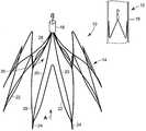
도 1 내지 도 3은 혈관(12)의 강(腔) 내에서 필터 구조 내에 배치된 변환가능한 필터 조립체(10)를 개략적으로 나타낸다. 변환가능한 필터 조립체(10)는 도 1에 도시한 바와 같이, 제거가능한 필터 헤드(16)에 의해 필터 구조에 고정된 다수의 강내 필터 요소(필터 요소)(14)를 포함한다. 본 명세서에서 사용한 바와 같이, "필터 구조"란 용어는 혈관계 질병의 치료를 위해 혈관(12) 내에 위치했을 때의 변 환가능한 필터 조립체(10)를 말한다. 마찬가지로, "개방 구조"나 "스텐트형 구조"란 용어는 필터 요소(14)에서 분리된 제거가능한 필터 헤드(16)를 갖는 변환가능한 필터 조립체(10), 및 혈관(12)의 벽(18)을 따라 연장된 구속되지 않은 필터요소(14)를 말한다.1-3 show schematically a
이 실시예에 있어서 필터 요소(14)는 단일 콘 구조로 배열되며, 가령, 제거한 혈전이나 혈소판 같이 혈류 내에서 운반되는 물질을 포집하도록 화살표(A)로 표시된 혈류의 방향으로 혈관(12) 내에 정렬된다. 필터 요소(14)는 각각 절곡점(24)에서 배향 부재(22)에 유연하게 부착된 필터 다리(20)를 포함한다. 동작시, 혈관(16) 내에서 변환가능한 필터 조립체(10)의 전개는 배향부재(22)로 하여금 혈관(12)의 벽과 결합되고 변환가능한 필터 조립체(10) 전체가 혈류와 정렬되도록 허용한다. 그러나, 변환가능한 필터, 단일 콘, 이중 콘, 바스킷, 안정화 부재, 비안정화 부재 등의 특정한 구조는 중요한 것이 아니며, 본 명세서에 기술한 제거가능한 필터 헤드는 그러한 어떤 수직 구조에도 적용할 수 있음을 주목해야 한다.In this embodiment the
필터 다리(20)는 배향 부재(22)에 의해서 혈관(12)의 벽(18)을 따라서 정렬된 하단부(26) 및 상단부(28)를 구비한다. 특히, 하단부(26)는 상단부(28)로부터 상류에 위치한 필터 다리(20)의 고정되지 않은 부분이다. 상단부(28)는 이어서 제거가능한 필터 헤드(16)에 의해 함께 다발로 묶여서 참조 부호 (30)으로 개략적으로 나타낸 필터 바스킷을 형성한다. 독자의 이해를 돕기 위해 본 명세서에서 사용한 바와 같이, 상부와 하부란 용어는 혈관(12) 내에서 및 혈류의 방향(화살표 (A)로 나타냄)에 대해서 변환가능한 필터 조립체(10)의 배향을 가리킨다. 예를 들면, 하부란 용어는 혈관(12) 내에서 혈류의 방향에 대한 하류 위치를 가리키고, 상류란 용어는 그에 대한 상류위치를 가리킨다.The
제거가능한 필터 헤드(16), 필터 다리(20) 및 배향 부재(22)를 포함하는 변환가능한 필터 조립체(10)는 국제 표준화 기구(ISO)에 의해 의료 기기에서 사용하도록 인증된 방사선불투과성의 비강자성 금속으로 제조할 수 있다. 필터 다리(20)와 배향 부재(22)는 가령, 둥글거나 평탄한 단면, 또는 적합한 임의의 단면 형상을 갖는 금속선으로 제조할 수 있다. 변환가능한 필터 조립체(10)는 추가로 약제 코팅할 수 있다.The
상기 선은 PHYNOX로도 불리는 등록 상표 ELGILOY®로서 판매되는 합금과 같은 고(高)코발트, 저(低)철 합금일 수 있다. 이들 합금의 조성은 중량%로, 최대 0.15%의 탄소와 0.001%의 베릴륨을 갖는 탄소 및 베릴륨으로 이루어진 밸런스를 갖는 코발트 42%, 크롬 21.5%, 니켈 18%, 철 8.85%, 몰리브덴 7.5%, 마그네슘 2%일 수 있다. 상기 선은 316L 스테인리스 스틸이나, 그 밖에 등록 상표 NITINOL®로 제조 및 판매되는 형상기억금속으로 알려진 니켈 및 타늄 합금 또는 탄탈륨(Ta) 합금으로 조성할 수 있다. 이들 금속으로 만들어진 변환가능한 필터 조립체(10)는 비혈액응고성이며, 기계적인 실패 없이 1200만 호흡 사이클에 견디는 것이 바람직하다.The line may be a high cobalt, low iron alloy, such as an alloy sold under the trademark ELGILOY®, also referred to as PHYNOX. The composition of these alloys is by weight, with a balance of up to 0.15% carbon, carbon with 0.001% beryllium and beryllium, 42% cobalt, 21.5% chromium, 18% nickel, 8.85% iron, 7.5% molybdenum, magnesium May be 2%. The wire may be composed of 316L stainless steel or other nickel and tan alloys or tantalum (Ta) alloys known as shape memory metals manufactured and sold under the trademark NITINOL®. The
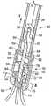
도 2 및 도 3은 혈관(12) 내에 배치되고 올가미 카테터(32)와 정렬되는 변환가능한 필터 조립체(10)를 개략적으로 나타낸다. 특히, 도 2 및 도 3은 올가미 카테터(32)에 의한 제거가능한 필터 헤드(16)의 정렬 및 포획을 나타낸다. 올가미 카테터(32) 또는 다른 임의의 적합한 파지 기구를 알려진 삽입 및 전개방법에 의해서 혈관의 강 안으로 삽입할 수 있으며, 환자의 순환계를 통해서 제거가능한 필터 헤드(16) 및 필터 다리(20)의 상단부(28)와 인접한 위치까지 조종할 수 있다. 올가미 카테터(32)는 외통(sheath)(34) 및 외통(34)에 대해 미끄럼이동 가능한 가령 S자 형상 올가미나 후크와 같은 올가미(36)를 구비할 수 있다. 마찬가지로, 제거가능한 필터 헤드(16)는 올가미(34)에 의해서 결합되도록 적용된 걸쇠(catch)(38)나 후크를 구비할 수 있다.2 and 3 schematically show a
도 3은 혈관(12) 내에 배치되고 올가미 카테터(32)에 의해서 결합된 제거가능한 필터 헤드(16)의 확대 단면도를 나타낸다. 특히, 도 3은 환자의 순환계나 심장혈관계를 통해서 제거가능한 필터 헤드(16)에 인접한 위치까지 조종된 올가미 카테터(32)를 나타낸다. 이 위치에서, 올가미(36)는 둥글게 고리로 만들거나 걸쇠(38)를 걸어서 올가미 카테터(32)와 외통(34)을 제거가능한 필터 헤드(16)에 미끄럼이동 가능하게 고정할 수 있다. 화살표(T)로 나타낸 방향으로 장력이 증가함에 따라서, 외통(34)이 제거가능한 필터 헤드(16) 쪽으로 동시에 미끄럼 이동하는 동안 올가미(36)는 외통(34) 안으로 후퇴할 수 있다. 가해진 장력(T)은 올가미(36)를 외통(24) 내로 끌어당기기에 충분하지만, 혈관(12)의 벽(18)에 대한 변환가능한 필터 조립체(10)의 전체 위치를 이동시키거나 방해할 정도로 충분히 크지는 않다.3 shows an enlarged cross-sectional view of the
도 4는 제거가능한 필터 헤드(16)와 인접한 관계에 있는 올가미 카테터(32)의 확대 단면도를 나타낸다. 특히, 올가미 카테터(32)는 제거가능한 필터 헤 드(16)와 인접한 관계에서, 외통(34)의 끝단부로서 규정된 팁(40)을 포함한다. 도시한 바와 같이, 팁(40)은 제거가능한 필터 헤드(16)에 대해 견고하게 안착되어 있으며, 올가미(36)와 걸쇠(38)는 중공 내부(42)로 후퇴되어 있다.4 shows an enlarged cross-sectional view of the
제거가능한 필터 헤드(16)는 제 1개방 단부(46) 및 그 안에 일체로 형성된 리테이너(50)를 갖는 제 2단부(48)를 포함하는 대략 원통형의 몸체(44)이다. 제 1개방 단부(46)는 대략 원통형의 몸체(44)를 밀폐 및/또는 밀봉할 수 있는 크기로 된 엔드 캡(52)을 수용한다. 엔드 캡(52)은 원통형 몸체(44)의 상부 테두리(60)에 대해 안착될 수 있는 입구(56)와, 원통형 몸체(44)의 입구(56) 및 상부 테두리(60)가 인접하는 관계로 있도록 원통형 몸체(44)의 내부면과 협동할 수 있는 크기로 된 원통형 벽(58)을 구비한다. 원통형 벽(58)과 원통형 몸체(44)는 압입 또는 마찰 배열에 의해 서로 유지될 수 있고, 수나사와 암나사를 구비하여 회전가능하게 결합될 수 있으며, 점착, 용접이나 그 밖에 원하는 어떤 방법으로 서로 고정할 수 있다. 엔드 캡은 올가미(36)와 걸쇠(38)가 중공 내부(42) 안으로 후퇴될 때, 외통(34)의 팁(40)에 대해 유지되거나 가압되도록 배열된 외부 평탄면(54)을 더 구비할 수 있다. 평탄면(54)은 제거가능한 필터 헤드(16)와 올가미 카테터(32)의 2개의 부품 간에 견고한 접촉을 제공하여, 그들 간의 힘의 전달을 허용한다.The
엔드 캡(52)은 걸쇠(38)에 연결된 로드부(64)를 미끄럼이동 가능하게 수용할 수 있는 크기로 된 오리피스(62)를 더 구비할 수 있다. 로드부(64)는 오리피스(62)를 통해서 원통형 몸체(44)의 내부로 연장되어 연속적으로 형성된 축(68)을 갖는 스토퍼(70)와 결합한다. 이 실시예에서 도시한 바와 같이, 스토퍼(70)는 원 통형 몸체(44)의 제 2단부(48)에 형성된 리테이너(50)와 분리가능하게 결합할 수 있는 크기로 된 대략 원통형의 부품이다. 동작시에, 스토퍼(70)는 리테이너(50)에 인접한 고정위치와 엔드캡(54)에 인접한 비고정 위치 사이에서 원통형 몸체(44)의 내부에서 이동할 수 있다.The
스토퍼(70)는 플랜지(72)와 플러그(74)를 규정하는 다양한 직경부를 구비한다. 본 실시예에 있어서, 플랜지(72) 및 플러그(74)는 축(68) 및 로드부(64)와 동축적으로 정렬되는 일체형 요소이다. 물리적으로, 플랜지(72)는 원통형 몸체(44)의 내부(66)를 따르는 반경방향 연장형 디스크이며, 플러그(74)는 스토퍼(70)가 고정위치에 있을 때, 리테이너(50)와 협동할 수 있는 크기로 되고, 플랜지(72)에 비해서 감소된 직경을 갖는다. 도시한 바와 같이, 축(68)은 가령, 나사 또는 압입 구성으로 로드부(64)를 확실히 수용할 수 있는 크기로 된 블라인드 구멍(76)을 구비할 수 있다. 제거가능한 필터 헤드(16)는 리테이너(50)와 확실히 접촉된 상태에서 축(68)과 플랜지(72)를 통해서 스토퍼(70)를 지지하기 위해, 엔드 캡(52)의 원통형 벽(58)에 인접하게 배치된 푸시 너트(78)를 더 포함할 수 있다.The
화살표(T)로 표시된 방향으로 걸쇠(38)와 로드부(62)를 통해 가해진 힘에 의해 축(68)은 푸시 너트(78)를 탄성 변형시켜 엔드캡(52)의 원통형 벽(58)에 인접한 비고정 위치까지 스토퍼(70)가 이동되도록 허용한다. 원통형 벽(58)과 푸시 너트(78)는 플랜지(72)와 협동하여 엔드 캡(52)에 인접한 비고정 위치까지 스토퍼(70)의 전체 운동을 제한한다. 축(68)은 플랜지(72)에 인접하고, 제 1개방 단부(46)에서 비고정 위치까지의 이동시에 스토퍼(70)와 플러그가 리테이너(50)와 재 결합하는 것을 막기 위해 푸시 너트(78)와 협동하도록 배열된 감소된 직경부(80)를 더 구비한다.By the force applied through the
플러그(74)와 리테이터(50)는 스토퍼(70)가 고정 위치에 있을 때, 필터 다리(20)의 상단부(28)를 압축 결합하여 유지하도록 협동한다. 필터 다리(20)의 상단부(28)는 원통형 몸체(44)의 제 2단부(48)에서 리테이너(50) 내에 형성된 다수의 홈(82)(도 5 참조) 내에 정렬될 수 있다. 정렬된 필터 다리(20)는 이어서 리테이너(50) 안으로 삽입되는 플러그(74)를 삽입하여 이들 사이에 간섭용 끼워맞춤부를 생성함으로써 제위치에 유지된다. 또한, 플랜지(72)는 리테이너(50)에 대해 정렬된 필터 다리(20)의 상단부를 압축 결합할 수 있는 배열 및 크기로 될 수 있다. 이 방식으로, 필터 다리(20)의 상단부(28)는 제거가능한 필터 헤드(16)의 원통형 몸체(44) 내에 결합 및 고정됨으로써, 필터 바스킷(30)을 생성한다.The
도 6은 올가미 카테터(32)의 팁(40)과 접촉 관계에 있는 제거가능한 필터 헤드(16)의 확대 단면도를 나타낸다. 특히, 팁(40)이 평탄면(54)에 대해 견고하게 안착되도록 걸쇠(38)와 올가미(36)는 외통(34) 안으로 후퇴한다. 또한, 화살표(T)로 나타낸 방향으로 올가미(26)와 걸쇠(38)를 통한 장력이 제공되어, 스토퍼(70)는 엔드 캡(52)에 인접한 비고정 위치를 향해 강제로 이동된다.6 shows an enlarged cross-sectional view of the
스토퍼(70)의 이동은 이어서 축(68)으로 하여금 푸시 너트(78)에 대해 견디면서 탄성 변형되도록 한다. 특히, 스토퍼의 이동은 푸시 너트(78)의 핑거(finger)(참조 부호 (78a) 및 (78b)로 나타냄)를 변형시킨다. 탄성적으로 변형된 핑거(78a, 78b)는 축(68)을 타게 되며, 감소된 직경부(80)와 결합하여, 스토 퍼(70)가 리테이너(50)에 인접한 고정 위치로 복귀하는 것을 막는다. 마찬가지로, 플랜지(72)는 원통형 벽(58)과 맞물려서 엔드 캡(52) 방향으로의 추가적인 이동이나 타고 넘어가는 것이 방지된다. 이와 같이 해서, 스토퍼(70)는 엔드 캡(52)과 리테이너(50) 사이에서 리테이너(50)로부터 떨어진 비고정 위치에 록크된다. 감소된 직경부(80)는 스토퍼(70)가 비고정 위치에 도달하도록 멈춤부로서 추가적으로 작용할 수 있으며, 이것은 감소된 직경부와 맞물려서 스토퍼를 비고정 위치에 유지시킨다. 축(68)으로부터 감소된 직경부까지 미끄럼 이동하는 핑거의 작용은 카테터를 통해 접촉식 스냅이나 클릭 표수부를 제공하여, 의료 전문가로 하여금 스토퍼(70)가 비고정 위치에 충분히 도달하였음을 알 수 있게 한다.Movement of the
스토퍼(70)를 끌어당기고 푸시 너트(78)를 탄성적으로 변형시키도록 적용된 장력은, 혈관벽(18)에 반력을 가하기 위해 변환가능한 필터 조립체(10) 전체가 이동할 수 있도록 한다. 혈관벽으로 전달되는 힘을 제한하기 위해서, 올가미(36)를 통해 가해진 장력은 외통(34)을 통해 평탄면(54)에 가해진 동일 및 대항하는 힘에 의해서 상쇄되거나 균형을 이룬다. 이와 같이 해서, 걸쇠(38) 및 부착된 스토퍼(70)에는 리테이너(50)로부터 분리되도록 힘이 가해지는 한편, 외통(34)을 통해 가해진 반력은 혈관벽(18)에 대해 제거가능한 필터 헤드(16) 및 부착된 필터 요소(14)의 위치를 유지한다.The tension applied to attract the
도 6에 도시한 바와 같이, 리테이너(50)로부터 플러그(74)가 분리되면, 스토퍼(70)는 감소된 직경부(80)와 푸시 너트(78)의 핑거(78a, 78b)의 협동에 의해서 엔드 캡(52)에 인접하게 고정된 상태로 유지된다. 필터 다리(20)의 상단부(28)는 전형적으로 리테이너(50)의 홈(82) 내에 결합된 상태로 유지되지만, 해방되어 자유로운 상태로 될 준비가 되어 있다. 이 배열은 리테이너(50)로부터 필터 다리(20)의 상단부(28)의 분리에 의해서 변환가능한 필터 조립체(10)가 필터 구조에서 개방 또는 스텐트형 구조로 변환되도록 허용한다.As shown in FIG. 6, when the
상술한 바와 같이, 변환가능한 필터 조립체(10)의 변환 공정은 올가미 카테터(32) 및 올가미(36)와 제거가능한 필터 헤드(16) 및 걸쇠(38)의 조종 및 정렬로부터 시작된다. 정렬된 올가미(36)는 걸쇠(38)와 결합되며, 외통(34)은 엔드 캡(52)의 평탄면(54)과 접촉한 상태에서 위치결정된다. 이와 같이 해서, 올가미 캐테터(32)의 팁(40)은 (엔드 캡(52)과의 접촉을 통해서) 제거가능한 필터 헤드(16)와 접하게 되며, 외통(34)은 올가미(36)와 걸쇠(38) 모두를 감싼다.As noted above, the conversion process of the
가령, 환자의 신체의 외부에 있는 올가미(36)의 끝단부와 같은 올가미(36)의 자유 단부에 화살표(T) 방향으로 가해진 장력은, 걸쇠(38)를 외통(34) 내로 더 깊숙이 당겨서 부착된 스토퍼(70)가 리테이너(50)로부터 강제로 분리되도록 한다. 단, 장력이 푸시 너트(78)의 핑거(78a, 78b)에 의해 생성된 힘 및 플러그(74)와 리테이너(50) 간의 마찰보다 크지 않는 한, 스토퍼(70)는 분리될 수 없음을 이해할 수 있을 것이다. 동시에, 올가미(36)를 통해 가해진 장력의 작용과 균형을 이루면서 반작용하기 위해서, 외통(34)을 통해서 제거가능한 필터 헤드(16)에 반력이 가해질 수 있다. 다시 말해서, 올가미(36)가 당겨져 리테이너(50)로부터 플러그(74)가 해방됨에 따라서, 외통(34)이 밀리면서 엔드 캡(52)의 평탄면(54)을 통해 제거가능한 필터 헤드(16)와 맞물려서, 혈관벽(18)에 대한 이동을 방지한다.For example, the tension exerted in the direction of the arrow T on the free end of the
플러그(74)와 리테이너(50) 간의 마찰을 극복함으로써, 축(68)은 푸시 너트(78)의 핑거(78a, 78b)를 탄성 변형시키게 되며, 스토퍼(70)는 리테이너(50)로부터 떨어져서 엔드 캡(52)에 인접한 비고정 위치까지 이동하도록 허용한다. 핑거(78a, 78b)는 이어서 감소된 직경부(80)와 맞물려 스토퍼(70)를 로킹시키거나 스토퍼가 리테이너(50)와 재결합하는 것을 방지한다. 플랜지(72)와 엔드 캡(52)의 원통형 벽(58) 간의 간섭에 의해서 스토퍼(70)의 이동이 더욱 제한된다. 이것은 제거가능한 필터 헤드(16) 내에서 기구를 해방하여, 스토퍼(70)가 리테이너(50)로부터 분리되어 부품들의 원하지 않는 재결합을 막도록 한다.By overcoming the friction between the
도 7은 스토퍼(70)와 플러그(74)가 리테이너(50)로부터 분리된 후의 제거가능한 필터 헤드(16)를 나타낸다. 구속되지 않은 필터 다리(20)의 상단부(28)는 홈(82)으로부터 분리되어 개방 또는 스텐트형 구조로 만곡되거나 확장되게 된다. 일반적으로, 제거가능한 필터 헤드(16)를 분리해서 필터 다리(20)의 상단부(28)을 분리하기 위해서, 제거가능한 필터 헤드(16) 전체는 올가미 카테터(32)를 통해서 혈관(12)의 벽(18)에 정박되거나 감싸인 필터 요소(14)로부터 멀어지면서 당겨진다. 이와 같이 해서, 제거가능한 필터 헤드(16)와 올가미 카테터(32)는 환자의 순환계를 통해 추출하기 위해서 필터 요소(14)로부터 분리된다. 필터 요소(14)는 개방 또는 스텐트형 구조로 혈관(12)의 벽(18)에 고정된 상태로 유지된다.7 shows the
도 7a는 스토퍼와 플러그(74)가 리테이너(50)로부터 분리된 후의 제거가능한 필터 헤드(16)의 다른 구성을 나타낸다. 동일한 참조 부호는 동일한 요소를 가리킨다. 리테이너(50)에는 필터 다리의 상단부(28)를 수용하는 매끈한 구멍이 형성 되어 있다. 스토퍼와 플러그(74)에는, 고정 위치에서는 필터 다리를 스토퍼와 플러그(74)와 결합 및 정렬시키는 한편 도 7a에 도시한 바와 같이 비고정 위치에 있을 때에는 필터 다리를 해방시키는 홈(82')이 형성되어 있다. 단, 홈(82/82')이 리테이너(50) 또는 플러그(74)의 하나 또는 둘 모두에 형성되는 다른 구성도 사용할 수 있다.7A shows another configuration of the
도 8은 혈관(12)의 벽(18)을 따라서 확장 및 연장되는 해방된 강내 필터 요소(14)를 나타낸다. 이 개방 또는 스텐트형 구조에 있어서, 필터 바스킷(30)은 개방되어 혈관(12)을 통해서 혈액이 자류롭게 흐르도록 허용한다.8 shows a freed
비록 특정 실시예를 본 개시내용의 교시에 따라서 설명하였으나, 본 발명의 범위와 적용 범위는 이들로 한정되는 것은 아니다. 예를 들어, 변환가능한 필터 요소(14)를 도시하고 원통형 몸체를 갖는 것으로 설명하였으나, 원하는 임의의 형상 또는 구성을 채용할 수 있음을 이해할 수 있을 것이다. 또한, 본 명세서에는 강내 필터 요소(14)의 특정 실시예를 설명하였으나, 많은 다른 단일 또는 이중 콘 구성도 채용할 수 있다. 본 발명은 허용가능한 동등물의 범위 내에 분명히 들어가는 본 개시내용의 교시의 모든 실시예들을 커버하도록 의도되어 있다.Although specific embodiments have been described in accordance with the teachings of the present disclosure, the scope and scope of application of the present invention is not limited thereto. For example, while the
Claims (15)
Translated fromKoreanApplications Claiming Priority (2)
| Application Number | Priority Date | Filing Date | Title |
|---|---|---|---|
| US66803605P | 2005-04-04 | 2005-04-04 | |
| US60/668,036 | 2005-04-04 |
Publications (1)
| Publication Number | Publication Date |
|---|---|
| KR20070117705Atrue KR20070117705A (en) | 2007-12-12 |
Family
ID=36698911
Family Applications (1)
| Application Number | Title | Priority Date | Filing Date |
|---|---|---|---|
| KR1020077025547AWithdrawnKR20070117705A (en) | 2005-04-04 | 2006-04-04 | Removable filter head |
Country Status (11)
| Country | Link |
|---|---|
| US (2) | US20070032816A1 (en) |
| EP (1) | EP1868526B1 (en) |
| JP (1) | JP2008534223A (en) |
| KR (1) | KR20070117705A (en) |
| AU (1) | AU2006231488A1 (en) |
| BR (1) | BRPI0610660A2 (en) |
| CA (1) | CA2603760A1 (en) |
| IL (1) | IL186406A0 (en) |
| NO (1) | NO20075160L (en) |
| RU (1) | RU2007140889A (en) |
| WO (1) | WO2006107939A1 (en) |
Cited By (1)
| Publication number | Priority date | Publication date | Assignee | Title |
|---|---|---|---|---|
| KR101133157B1 (en)* | 2009-10-13 | 2012-04-06 | 연세대학교 산학협력단 | Detachable and retrievable embolic protection device and filter assembly composing the same |
Families Citing this family (50)
| Publication number | Priority date | Publication date | Assignee | Title |
|---|---|---|---|---|
| US7976562B2 (en) | 2004-01-22 | 2011-07-12 | Rex Medical, L.P. | Method of removing a vein filter |
| US8162972B2 (en) | 2004-01-22 | 2012-04-24 | Rex Medical, Lp | Vein filter |
| US8062326B2 (en) | 2004-01-22 | 2011-11-22 | Rex Medical, L.P. | Vein filter |
| US7704266B2 (en) | 2004-01-22 | 2010-04-27 | Rex Medical, L.P. | Vein filter |
| US8211140B2 (en)* | 2004-01-22 | 2012-07-03 | Rex Medical, L.P. | Vein filter |
| US9510929B2 (en) | 2004-01-22 | 2016-12-06 | Argon Medical Devices, Inc. | Vein filter |
| US8500774B2 (en) | 2004-01-22 | 2013-08-06 | Rex Medical, L.P. | Vein filter |
| ES2444590T3 (en)* | 2004-09-27 | 2014-02-25 | Rex Medical, L.P. | Venous filter |
| US20070112372A1 (en)* | 2005-11-17 | 2007-05-17 | Stephen Sosnowski | Biodegradable vascular filter |
| US20080097620A1 (en)* | 2006-05-26 | 2008-04-24 | Nanyang Technological University | Implantable article, method of forming same and method for reducing thrombogenicity |
| EP2043551B1 (en) | 2006-07-19 | 2018-05-09 | Novate Medical Limited | A vascular filter |
| US10076401B2 (en) | 2006-08-29 | 2018-09-18 | Argon Medical Devices, Inc. | Vein filter |
| US20080269774A1 (en)* | 2006-10-26 | 2008-10-30 | Chestnut Medical Technologies, Inc. | Intracorporeal Grasping Device |
| US8795351B2 (en) | 2007-04-13 | 2014-08-05 | C.R. Bard, Inc. | Migration resistant embolic filter |
| US8795318B2 (en)* | 2007-09-07 | 2014-08-05 | Merit Medical Systems, Inc. | Percutaneous retrievable vascular filter |
| WO2009032834A1 (en) | 2007-09-07 | 2009-03-12 | Crusader Medical Llc | Percutaneous permanent retrievable vascular filter |
| US8343029B2 (en)* | 2007-10-24 | 2013-01-01 | Circulite, Inc. | Transseptal cannula, tip, delivery system, and method |
| US8206635B2 (en) | 2008-06-20 | 2012-06-26 | Amaranth Medical Pte. | Stent fabrication via tubular casting processes |
| US8206636B2 (en) | 2008-06-20 | 2012-06-26 | Amaranth Medical Pte. | Stent fabrication via tubular casting processes |
| US10898620B2 (en) | 2008-06-20 | 2021-01-26 | Razmodics Llc | Composite stent having multi-axial flexibility and method of manufacture thereof |
| US20100016881A1 (en)* | 2008-07-16 | 2010-01-21 | Cook Incorporated | Biodegradable filter |
| US8025675B2 (en)* | 2008-08-14 | 2011-09-27 | Cook Medical Technologies Llc | Temporary filter device |
| CA2736138A1 (en) | 2008-09-05 | 2010-03-11 | Christoph Andreas Binkert | Blood filter |
| WO2010082188A1 (en)* | 2009-01-16 | 2010-07-22 | Novate Medical Limited | A vascular filter device |
| US8057507B2 (en) | 2009-01-16 | 2011-11-15 | Novate Medical Limited | Vascular filter |
| US20100228281A1 (en)* | 2009-01-16 | 2010-09-09 | Paul Gilson | Vascular filter system |
| EP2381893B1 (en) | 2009-01-16 | 2018-03-07 | Novate Medical Ltd. | A vascular filter device |
| US20110152918A1 (en)* | 2009-12-23 | 2011-06-23 | Pavilion Medical Innovations | Reversible Vascular Filter Devices and Methods for Using Same |
| EP2651502B1 (en) | 2010-12-13 | 2016-11-09 | Pacesetter, Inc. | Pacemaker retrieval systems |
| US20120221040A1 (en) | 2011-02-28 | 2012-08-30 | Mitchell Donn Eggers | Absorbable Vascular Filter |
| US10531942B2 (en) | 2011-02-28 | 2020-01-14 | Adient Medical, Inc. | Absorbable vascular filter |
| US20120277787A1 (en)* | 2011-04-28 | 2012-11-01 | Mitchell Donn Eggers | Vascular Filter Stent |
| US8986283B2 (en) | 2011-05-18 | 2015-03-24 | Solo-Dex, Llc | Continuous anesthesia nerve conduction apparatus, system and method thereof |
| CA3065357C (en) | 2011-05-18 | 2023-04-25 | Solodex Llc | Continuous anesthesia nerve conduction apparatus, system and method |
| US8734480B2 (en) | 2011-08-05 | 2014-05-27 | Merit Medical Systems, Inc. | Vascular filter |
| US8740931B2 (en) | 2011-08-05 | 2014-06-03 | Merit Medical Systems, Inc. | Vascular filter |
| CN104023656B (en)* | 2011-12-05 | 2017-02-15 | Pi-R-方形有限公司 | Calcium deposits in broken heart valves |
| EP2816969B1 (en) | 2012-02-23 | 2018-06-13 | Merit Medical Systems, Inc. | Vascular filter |
| US9668850B2 (en) | 2012-07-06 | 2017-06-06 | Cook Medical Technologies Llc | Conical vena cava filter with jugular or femoral retrieval |
| US9308073B2 (en)* | 2012-09-12 | 2016-04-12 | Cook Medical Technologies Llc | Vena cava filter with dual retrieval |
| FR2998165B1 (en) | 2012-11-21 | 2015-12-04 | Braun B Med Sas | VEIN FILTER |
| WO2014140088A2 (en)* | 2013-03-15 | 2014-09-18 | Novate Medical Limited | A vascular filter device |
| EP3030194B1 (en) | 2013-08-09 | 2019-03-13 | Merit Medical Systems, Inc. | Vascular filter delivery systems |
| US10010398B2 (en)* | 2013-10-01 | 2018-07-03 | Cook Medical Technologies Llc | Filter device, system, and method |
| US10123863B2 (en) | 2014-03-28 | 2018-11-13 | Cook Medical Technologies Llc | Mechanism for applying high radial force in less-elastic medical devices |
| GB2531587A (en)* | 2014-10-23 | 2016-04-27 | Cook Medical Technologies Llc | Implantable medical device exhibiting diminishing radial force |
| CN105496600B (en)* | 2015-12-31 | 2020-09-29 | 先健科技(深圳)有限公司 | Catching device |
| EP3398555B1 (en)* | 2015-12-31 | 2023-07-26 | Lifetech Scientific (Shenzhen) Co., Ltd. | Catcher |
| CN107684452B (en)* | 2016-08-04 | 2021-05-07 | 先健科技(深圳)有限公司 | catcher |
| CN111388140B (en)* | 2020-02-25 | 2025-02-14 | 甘肃省人民医院 | A venous filter |
Family Cites Families (89)
| Publication number | Priority date | Publication date | Assignee | Title |
|---|---|---|---|---|
| US344141A (en)* | 1886-06-22 | Drain-tile protector | ||
| US2281448A (en)* | 1941-09-17 | 1942-04-28 | Scully Signal Co | Device for partially obstructing pipes |
| US3281448A (en)* | 1963-05-17 | 1966-10-25 | Fmc Corp | Chlorination of phenylene diisocyanate |
| US3334629A (en)* | 1964-11-09 | 1967-08-08 | Bertram D Cohn | Occlusive device for inferior vena cava |
| US3540431A (en)* | 1968-04-04 | 1970-11-17 | Kazi Mobin Uddin | Collapsible filter for fluid flowing in closed passageway |
| US3868956A (en)* | 1972-06-05 | 1975-03-04 | Ralph J Alfidi | Vessel implantable appliance and method of implanting it |
| US3952747A (en)* | 1974-03-28 | 1976-04-27 | Kimmell Jr Garman O | Filter and filter insertion instrument |
| US4425908A (en)* | 1981-10-22 | 1984-01-17 | Beth Israel Hospital | Blood clot filter |
| US4643184A (en)* | 1982-09-29 | 1987-02-17 | Mobin Uddin Kazi | Embolus trap |
| US4494531A (en)* | 1982-12-06 | 1985-01-22 | Cook, Incorporated | Expandable blood clot filter |
| US4727873A (en)* | 1984-04-17 | 1988-03-01 | Mobin Uddin Kazi | Embolus trap |
| US4657543A (en)* | 1984-07-23 | 1987-04-14 | Massachusetts Institute Of Technology | Ultrasonically modulated polymeric devices for delivering compositions |
| FR2573646B1 (en)* | 1984-11-29 | 1988-11-25 | Celsa Composants Electr Sa | PERFECTED FILTER, PARTICULARLY FOR THE RETENTION OF BLOOD CLOTS |
| FR2580504B1 (en) | 1985-04-22 | 1987-07-10 | Pieronne Alain | FILTER FOR THE PARTIAL AND AT LEAST PROVISIONAL INTERRUPTION OF A VEIN AND CATHETER CARRYING THE FILTER |
| FR2606641B1 (en)* | 1986-11-17 | 1991-07-12 | Promed | FILTERING DEVICE FOR BLOOD CLOTS |
| US4817600A (en)* | 1987-05-22 | 1989-04-04 | Medi-Tech, Inc. | Implantable filter |
| US4873978A (en)* | 1987-12-04 | 1989-10-17 | Robert Ginsburg | Device and method for emboli retrieval |
| FR2632848A1 (en)* | 1988-06-21 | 1989-12-22 | Lefebvre Jean Marie | FILTER FOR MEDICAL USE |
| US4832055A (en)* | 1988-07-08 | 1989-05-23 | Palestrant Aubrey M | Mechanically locking blood clot filter |
| FI85223C (en)* | 1988-11-10 | 1992-03-25 | Biocon Oy | BIODEGRADERANDE SURGICAL IMPLANT OCH MEDEL. |
| US5152777A (en)* | 1989-01-25 | 1992-10-06 | Uresil Corporation | Device and method for providing protection from emboli and preventing occulsion of blood vessels |
| US5242462A (en)* | 1989-09-07 | 1993-09-07 | Boston Scientific Corp. | Percutaneous anti-migration vena cava filter |
| US5059205A (en)* | 1989-09-07 | 1991-10-22 | Boston Scientific Corporation | Percutaneous anti-migration vena cava filter |
| GB2238485B (en)* | 1989-11-28 | 1993-07-14 | Cook William Europ | A collapsible filter for introduction in a blood vessel of a patient |
| US5354295A (en)* | 1990-03-13 | 1994-10-11 | Target Therapeutics, Inc. | In an endovascular electrolytically detachable wire and tip for the formation of thrombus in arteries, veins, aneurysms, vascular malformations and arteriovenous fistulas |
| FR2660189B1 (en)* | 1990-03-28 | 1992-07-31 | Lefebvre Jean Marie | DEVICE INTENDED TO BE IMPLANTED IN A VESSEL WITH SIDE LEGS WITH ANTAGONIST TEETH. |
| US5160342A (en)* | 1990-08-16 | 1992-11-03 | Evi Corp. | Endovascular filter and method for use thereof |
| US5415630A (en)* | 1991-07-17 | 1995-05-16 | Gory; Pierre | Method for removably implanting a blood filter in a vein of the human body |
| CA2079417C (en)* | 1991-10-28 | 2003-01-07 | Lilip Lau | Expandable stents and method of making same |
| US5626605A (en)* | 1991-12-30 | 1997-05-06 | Scimed Life Systems, Inc. | Thrombosis filter |
| US5267776A (en)* | 1992-03-09 | 1993-12-07 | Fromson H A | Modular chair |
| FR2689388B1 (en)* | 1992-04-07 | 1999-07-16 | Celsa Lg | PERFECTIONALLY RESORBABLE BLOOD FILTER. |
| US5324304A (en)* | 1992-06-18 | 1994-06-28 | William Cook Europe A/S | Introduction catheter set for a collapsible self-expandable implant |
| FR2694491B1 (en)* | 1992-08-07 | 1994-09-30 | Celsa Lg | Triangular tab filters. |
| US5443478A (en)* | 1992-09-02 | 1995-08-22 | Board Of Regents, The University Of Texas System | Multi-element intravascular occlusion device |
| US5527338A (en)* | 1992-09-02 | 1996-06-18 | Board Of Regents, The University Of Texas System | Intravascular device |
| PT659073E (en)* | 1992-09-10 | 2002-06-28 | Childrens Medical Center | BIODEGRADABLE POLYMERIC MATRICES FOR SUSTAINED DELIVERY OF LOCAL ANESTHETIC AGENTS |
| FR2697995B1 (en)* | 1992-11-19 | 1994-12-30 | Celsa Lg | Removable blood filtration device, with variable rigidity, implantable in the body of a patient and allowing the injection of a treating product. |
| FR2699809B1 (en)* | 1992-12-28 | 1995-02-17 | Celsa Lg | Device which can selectively constitute a temporary blood filter. |
| EP0746236B1 (en)* | 1993-10-01 | 2003-08-20 | Boston Scientific Corporation | Improved vena cava filter |
| FR2710833B1 (en)* | 1993-10-05 | 1995-11-24 | Celsa Lg | Device for implanting a medical prosthesis in a conduit of a human or animal body and method for centering such a device. |
| US5624449A (en)* | 1993-11-03 | 1997-04-29 | Target Therapeutics | Electrolytically severable joint for endovascular embolic devices |
| ATE295127T1 (en)* | 1994-03-03 | 2005-05-15 | Boston Scient Ltd | DEVICE FOR DETECTING THE DIVISION OF A VASS OCCLUSION DEVICE |
| FR2718950A1 (en) | 1994-04-21 | 1995-10-27 | Braun Celsa Sa | Temporary or long-term blood filter |
| US5634942A (en)* | 1994-04-21 | 1997-06-03 | B. Braun Celsa | Assembly comprising a blood filter for temporary or definitive use and a device for implanting it |
| US5853420A (en)* | 1994-04-21 | 1998-12-29 | B. Braun Celsa | Assembly comprising a blood filter for temporary or definitive use and device for implanting it, corresponding filter and method of implanting such a filter |
| US5601595A (en)* | 1994-10-25 | 1997-02-11 | Scimed Life Systems, Inc. | Remobable thrombus filter |
| US6214025B1 (en)* | 1994-11-30 | 2001-04-10 | Boston Scientific Corporation | Self-centering, self-expanding and retrievable vena cava filter |
| DE69629865T2 (en)* | 1995-04-14 | 2004-07-15 | B. Braun Medical Sas | Intraluminal medical device, especially blood filter |
| US5713853A (en)* | 1995-06-07 | 1998-02-03 | Interventional Innovations Corporation | Methods for treating thrombosis |
| US5743905A (en)* | 1995-07-07 | 1998-04-28 | Target Therapeutics, Inc. | Partially insulated occlusion device |
| FR2737654B1 (en)* | 1995-08-10 | 1997-11-21 | Braun Celsa Sa | FILTRATION UNIT FOR THE RETENTION OF BLOOD CLOTS |
| AU690862B2 (en)* | 1995-12-04 | 1998-04-30 | Target Therapeutics, Inc. | Fibered micro vaso-occlusive devices |
| NL1002423C2 (en)* | 1996-02-22 | 1997-08-25 | Cordis Europ | Temporary filter catheter. |
| US5607478A (en)* | 1996-03-14 | 1997-03-04 | Meadox Medicals Inc. | Yarn wrapped PTFE tubular prosthesis |
| US5670161A (en) | 1996-05-28 | 1997-09-23 | Healy; Kevin E. | Biodegradable stent |
| US5669933A (en)* | 1996-07-17 | 1997-09-23 | Nitinol Medical Technologies, Inc. | Removable embolus blood clot filter |
| US6447530B1 (en)* | 1996-11-27 | 2002-09-10 | Scimed Life Systems, Inc. | Atraumatic anchoring and disengagement mechanism for permanent implant device |
| US6391044B1 (en)* | 1997-02-03 | 2002-05-21 | Angioguard, Inc. | Vascular filter system |
| US5893869A (en)* | 1997-02-19 | 1999-04-13 | University Of Iowa Research Foundation | Retrievable inferior vena cava filter system and method for use thereof |
| US5800457A (en)* | 1997-03-05 | 1998-09-01 | Gelbfish; Gary A. | Intravascular filter and associated methodology |
| US5911734A (en)* | 1997-05-08 | 1999-06-15 | Embol-X, Inc. | Percutaneous catheter and guidewire having filter and medical device deployment capabilities |
| FR2768326B1 (en) | 1997-09-18 | 1999-10-22 | De Bearn Olivier Despalle | TEMPORARY BLOOD FILTER |
| US6375612B1 (en)* | 1998-03-24 | 2002-04-23 | P. Timothy Guichon | Method and system for monitoring animals |
| US6241746B1 (en)* | 1998-06-29 | 2001-06-05 | Cordis Corporation | Vascular filter convertible to a stent and method |
| US6306163B1 (en)* | 1998-08-04 | 2001-10-23 | Advanced Cardiovascular Systems, Inc. | Assembly for collecting emboli and method of use |
| US6342062B1 (en)* | 1998-09-24 | 2002-01-29 | Scimed Life Systems, Inc. | Retrieval devices for vena cava filter |
| US6007558A (en)* | 1998-09-25 | 1999-12-28 | Nitinol Medical Technologies, Inc. | Removable embolus blood clot filter |
| US6241766B1 (en)* | 1998-10-29 | 2001-06-05 | Allergan Sales, Inc. | Intraocular lenses made from polymeric compositions |
| US6102932A (en)* | 1998-12-15 | 2000-08-15 | Micrus Corporation | Intravascular device push wire delivery system |
| US6171327B1 (en) | 1999-02-24 | 2001-01-09 | Scimed Life Systems, Inc. | Intravascular filter and method |
| US6231589B1 (en)* | 1999-03-22 | 2001-05-15 | Microvena Corporation | Body vessel filter |
| US6080178A (en)* | 1999-04-20 | 2000-06-27 | Meglin; Allen J. | Vena cava filter |
| US6267776B1 (en)* | 1999-05-03 | 2001-07-31 | O'connell Paul T. | Vena cava filter and method for treating pulmonary embolism |
| US6702834B1 (en)* | 1999-12-30 | 2004-03-09 | Advanced Cardiovascular Systems, Inc. | Embolic protection devices |
| US6342063B1 (en)* | 2000-01-26 | 2002-01-29 | Scimed Life Systems, Inc. | Device and method for selectively removing a thrombus filter |
| US6540767B1 (en)* | 2000-02-08 | 2003-04-01 | Scimed Life Systems, Inc. | Recoilable thrombosis filtering device and method |
| AU2001241603A1 (en)* | 2000-02-23 | 2001-09-03 | Boston Scientific Limited | Intravascular filtering devices and methods |
| US6582447B1 (en)* | 2000-10-20 | 2003-06-24 | Angiodynamics, Inc. | Convertible blood clot filter |
| US6506205B2 (en)* | 2001-02-20 | 2003-01-14 | Mark Goldberg | Blood clot filtering system |
| FR2824726B1 (en) | 2001-05-18 | 2003-09-26 | Braun Medical | CONVERTIBLE FILTER WITH IMPROVED OPENING |
| JP4294470B2 (en) | 2001-06-14 | 2009-07-15 | クック インコーポレイテッド | Intravascular filter |
| US6881218B2 (en)* | 2002-05-01 | 2005-04-19 | Angiodynamics, Inc. | Blood clot filter |
| US6972030B2 (en)* | 2002-09-17 | 2005-12-06 | Lee Don W | Stent with combined distal protection device |
| US6786739B2 (en)* | 2002-09-30 | 2004-09-07 | Intel Corporation | Bridge clip with reinforced stiffener |
| US7763063B2 (en)* | 2003-09-03 | 2010-07-27 | Bolton Medical, Inc. | Self-aligning stent graft delivery system, kit, and method |
| US8231649B2 (en)* | 2004-01-20 | 2012-07-31 | Boston Scientific Scimed, Inc. | Retrievable blood clot filter with retractable anchoring members |
| US7678129B1 (en)* | 2004-03-19 | 2010-03-16 | Advanced Cardiovascular Systems, Inc. | Locking component for an embolic filter assembly |
| US20060015137A1 (en)* | 2004-07-19 | 2006-01-19 | Wasdyke Joel M | Retrievable intravascular filter with bendable anchoring members |
- 2006
- 2006-04-04WOPCT/US2006/012453patent/WO2006107939A1/enactiveApplication Filing
- 2006-04-04USUS11/278,601patent/US20070032816A1/ennot_activeAbandoned
- 2006-04-04JPJP2008505438Apatent/JP2008534223A/enactivePending
- 2006-04-04RURU2007140889/14Apatent/RU2007140889A/ennot_activeApplication Discontinuation
- 2006-04-04AUAU2006231488Apatent/AU2006231488A1/ennot_activeAbandoned
- 2006-04-04KRKR1020077025547Apatent/KR20070117705A/ennot_activeWithdrawn
- 2006-04-04BRBRPI0610660-9Apatent/BRPI0610660A2/ennot_activeApplication Discontinuation
- 2006-04-04CACA002603760Apatent/CA2603760A1/ennot_activeAbandoned
- 2006-04-04EPEP06740474.9Apatent/EP1868526B1/enactiveActive
- 2006-04-04USUS11/910,595patent/US8734481B2/enactiveActive
- 2007
- 2007-10-07ILIL186406Apatent/IL186406A0/enunknown
- 2007-10-10NONO20075160Apatent/NO20075160L/ennot_activeApplication Discontinuation
Cited By (1)
| Publication number | Priority date | Publication date | Assignee | Title |
|---|---|---|---|---|
| KR101133157B1 (en)* | 2009-10-13 | 2012-04-06 | 연세대학교 산학협력단 | Detachable and retrievable embolic protection device and filter assembly composing the same |
Also Published As
| Publication number | Publication date |
|---|---|
| US8734481B2 (en) | 2014-05-27 |
| WO2006107939A1 (en) | 2006-10-12 |
| US20070032816A1 (en) | 2007-02-08 |
| EP1868526A1 (en) | 2007-12-26 |
| CA2603760A1 (en) | 2006-10-12 |
| NO20075160L (en) | 2007-11-05 |
| BRPI0610660A2 (en) | 2010-07-13 |
| RU2007140889A (en) | 2009-05-20 |
| IL186406A0 (en) | 2008-01-20 |
| EP1868526B1 (en) | 2018-07-18 |
| AU2006231488A1 (en) | 2006-10-12 |
| US20110106133A1 (en) | 2011-05-05 |
| JP2008534223A (en) | 2008-08-28 |
Similar Documents
| Publication | Publication Date | Title |
|---|---|---|
| KR20070117705A (en) | Removable filter head | |
| US8100958B2 (en) | Device for delivering a self-expanding stent in a vessel of the body | |
| EP3643255B1 (en) | Clipping tool | |
| US8876879B2 (en) | Introducer | |
| US10188516B2 (en) | Stent loading tool and method for use thereof | |
| JP4986922B2 (en) | Interlock attachment / separation mechanism over wire | |
| EP3043755B1 (en) | Atraumatic interface in an implant delivery device | |
| EP2762083B1 (en) | Device for capturing debris in blood vessel | |
| US10226322B2 (en) | Jugular femoral vena cava filter system | |
| EP2862523B1 (en) | Release mechanism | |
| EP3001987B1 (en) | Apparatus for introducing intraluminal prostheses | |
| MX2007007073A (en) | Vascular thrombectomby apparatus and method of use. | |
| US8414640B2 (en) | Delivery system ejection component and method | |
| EP2783658B1 (en) | Medical device retrieval apparatus | |
| US8663302B2 (en) | Delivery system ejection component and method | |
| CN112716652A (en) | IVC filter recovery system with releasable capture feature | |
| US20160302794A1 (en) | Detachment mechanism for vascular devices | |
| WO2020121394A1 (en) | Medical device | |
| US20130261725A1 (en) | Stent holding structure for introducers |
Legal Events
| Date | Code | Title | Description |
|---|---|---|---|
| PA0105 | International application | Patent event date:20071102 Patent event code:PA01051R01D Comment text:International Patent Application | |
| PG1501 | Laying open of application | ||
| PC1203 | Withdrawal of no request for examination | ||
| WITN | Application deemed withdrawn, e.g. because no request for examination was filed or no examination fee was paid |