KR20070117608A - Unidirectional fixture - Google Patents
Unidirectional fixtureDownload PDFInfo
- Publication number
- KR20070117608A KR20070117608AKR1020077021948AKR20077021948AKR20070117608AKR 20070117608 AKR20070117608 AKR 20070117608AKR 1020077021948 AKR1020077021948 AKR 1020077021948AKR 20077021948 AKR20077021948 AKR 20077021948AKR 20070117608 AKR20070117608 AKR 20070117608A
- Authority
- KR
- South Korea
- Prior art keywords
- plate
- carriage
- bone
- carriage member
- channel
- Prior art date
- Legal status (The legal status is an assumption and is not a legal conclusion. Google has not performed a legal analysis and makes no representation as to the accuracy of the status listed.)
- Abandoned
Links
- 210000000988bone and boneAnatomy0.000claimsabstractdescription42
- 238000000034methodMethods0.000claimsabstractdescription27
- 238000011065in-situ storageMethods0.000claimsdescription3
- 230000000750progressive effectEffects0.000claimsdescription3
- 230000008878couplingEffects0.000abstractdescription11
- 238000010168coupling processMethods0.000abstractdescription11
- 238000005859coupling reactionMethods0.000abstractdescription11
- 125000006850spacer groupChemical group0.000description17
- 230000004927fusionEffects0.000description12
- 239000000463materialSubstances0.000description10
- 230000006835compressionEffects0.000description4
- 238000007906compressionMethods0.000description4
- 238000001356surgical procedureMethods0.000description4
- 230000000694effectsEffects0.000description3
- 230000002980postoperative effectEffects0.000description3
- 241000209094OryzaSpecies0.000description2
- 235000007164Oryza sativaNutrition0.000description2
- 210000000746body regionAnatomy0.000description2
- 230000001054cortical effectEffects0.000description2
- 238000002513implantationMethods0.000description2
- 238000012986modificationMethods0.000description2
- 230000004048modificationEffects0.000description2
- 230000004044responseEffects0.000description2
- 235000009566riceNutrition0.000description2
- 208000010392Bone FracturesDiseases0.000description1
- 229910001069Ti alloyInorganic materials0.000description1
- 238000007792additionMethods0.000description1
- 230000008468bone growthEffects0.000description1
- 238000005056compactionMethods0.000description1
- 230000007547defectEffects0.000description1
- 239000013013elastic materialSubstances0.000description1
- 229910000701elgiloys (Co-Cr-Ni Alloy)Inorganic materials0.000description1
- 239000007943implantSubstances0.000description1
- 230000005012migrationEffects0.000description1
- 238000013508migrationMethods0.000description1
- 230000000399orthopedic effectEffects0.000description1
- 230000008569processEffects0.000description1
- 239000012858resilient materialSubstances0.000description1
- 238000004062sedimentationMethods0.000description1
- 238000006467substitution reactionMethods0.000description1
- -1titanium-aluminum-niobiumChemical compound0.000description1
Images


Classifications
- A—HUMAN NECESSITIES
- A61—MEDICAL OR VETERINARY SCIENCE; HYGIENE
- A61B—DIAGNOSIS; SURGERY; IDENTIFICATION
- A61B17/00—Surgical instruments, devices or methods
- A61B17/56—Surgical instruments or methods for treatment of bones or joints; Devices specially adapted therefor
- A61B17/58—Surgical instruments or methods for treatment of bones or joints; Devices specially adapted therefor for osteosynthesis, e.g. bone plates, screws or setting implements
- A61B17/68—Internal fixation devices, including fasteners and spinal fixators, even if a part thereof projects from the skin
- A61B17/80—Cortical plates, i.e. bone plates; Instruments for holding or positioning cortical plates, or for compressing bones attached to cortical plates
- A61B17/8033—Cortical plates, i.e. bone plates; Instruments for holding or positioning cortical plates, or for compressing bones attached to cortical plates having indirect contact with screw heads, or having contact with screw heads maintained with the aid of additional components, e.g. nuts, wedges or head covers
- A61B17/8047—Cortical plates, i.e. bone plates; Instruments for holding or positioning cortical plates, or for compressing bones attached to cortical plates having indirect contact with screw heads, or having contact with screw heads maintained with the aid of additional components, e.g. nuts, wedges or head covers wherein the additional element surrounds the screw head in the plate hole
- A—HUMAN NECESSITIES
- A61—MEDICAL OR VETERINARY SCIENCE; HYGIENE
- A61B—DIAGNOSIS; SURGERY; IDENTIFICATION
- A61B17/00—Surgical instruments, devices or methods
- A61B17/56—Surgical instruments or methods for treatment of bones or joints; Devices specially adapted therefor
- A61B17/58—Surgical instruments or methods for treatment of bones or joints; Devices specially adapted therefor for osteosynthesis, e.g. bone plates, screws or setting implements
- A61B17/68—Internal fixation devices, including fasteners and spinal fixators, even if a part thereof projects from the skin
- A61B17/70—Spinal positioners or stabilisers, e.g. stabilisers comprising fluid filler in an implant
- A—HUMAN NECESSITIES
- A61—MEDICAL OR VETERINARY SCIENCE; HYGIENE
- A61B—DIAGNOSIS; SURGERY; IDENTIFICATION
- A61B17/00—Surgical instruments, devices or methods
- A61B17/56—Surgical instruments or methods for treatment of bones or joints; Devices specially adapted therefor
- A61B17/58—Surgical instruments or methods for treatment of bones or joints; Devices specially adapted therefor for osteosynthesis, e.g. bone plates, screws or setting implements
- A61B17/68—Internal fixation devices, including fasteners and spinal fixators, even if a part thereof projects from the skin
- A61B17/70—Spinal positioners or stabilisers, e.g. stabilisers comprising fluid filler in an implant
- A61B17/7059—Cortical plates
- A—HUMAN NECESSITIES
- A61—MEDICAL OR VETERINARY SCIENCE; HYGIENE
- A61B—DIAGNOSIS; SURGERY; IDENTIFICATION
- A61B17/00—Surgical instruments, devices or methods
- A61B17/56—Surgical instruments or methods for treatment of bones or joints; Devices specially adapted therefor
- A61B17/58—Surgical instruments or methods for treatment of bones or joints; Devices specially adapted therefor for osteosynthesis, e.g. bone plates, screws or setting implements
- A61B17/68—Internal fixation devices, including fasteners and spinal fixators, even if a part thereof projects from the skin
- A61B17/80—Cortical plates, i.e. bone plates; Instruments for holding or positioning cortical plates, or for compressing bones attached to cortical plates
- A61B17/8023—Variable length plates adjustable in both directions
- A—HUMAN NECESSITIES
- A61—MEDICAL OR VETERINARY SCIENCE; HYGIENE
- A61B—DIAGNOSIS; SURGERY; IDENTIFICATION
- A61B17/00—Surgical instruments, devices or methods
- A61B17/56—Surgical instruments or methods for treatment of bones or joints; Devices specially adapted therefor
- A61B17/58—Surgical instruments or methods for treatment of bones or joints; Devices specially adapted therefor for osteosynthesis, e.g. bone plates, screws or setting implements
- A61B17/68—Internal fixation devices, including fasteners and spinal fixators, even if a part thereof projects from the skin
- A61B17/84—Fasteners therefor or fasteners being internal fixation devices
Landscapes
- Health & Medical Sciences (AREA)
- Orthopedic Medicine & Surgery (AREA)
- Life Sciences & Earth Sciences (AREA)
- Surgery (AREA)
- Neurology (AREA)
- Heart & Thoracic Surgery (AREA)
- Engineering & Computer Science (AREA)
- Biomedical Technology (AREA)
- Nuclear Medicine, Radiotherapy & Molecular Imaging (AREA)
- Medical Informatics (AREA)
- Molecular Biology (AREA)
- Animal Behavior & Ethology (AREA)
- General Health & Medical Sciences (AREA)
- Public Health (AREA)
- Veterinary Medicine (AREA)
- Prostheses (AREA)
- Surgical Instruments (AREA)
Abstract
Translated fromKoreanDescription
Translated fromKorean본 발명은 고정 장치 분야에 관한 것이다. 보다 상세하게는, 본 발명은 단향성 이동 조절이 가능하도록 된 척추용 고정 시스템에 관한 것이다.The present invention relates to the field of fixing devices. More particularly, the present invention relates to a spinal fixation system that enables unidirectional movement control.
플레이트들과 같은 정형외과적 고정 장치들은 플레이트 구멍들을 관통하여 삽입된 파스너들(fastener)을 이용하여 뼈(bone)에 종종 연결된다. 예를 들어, 확장-헤드 스크류들의 이용을 통해, 그러한 파스너들을 뼈 플레이트에 고정하는 것은 수술 후 고정 조립체(assembly)가 느슨하게 되는 경향을 감소시킬 수 있다는 것이 알려져 있다. 또한, 파스너 구멍을 수납하는 각각의 플레이트 구멍에 부싱(bushing)이 배치되어 다축(polyaxial) 이동을 허용함으로써 외과의사에 의해 선택된 각도로 파스너가 각이 형성될 수 있음이 알려져 있다. 그러나, 설정된 플레이트 구멍 위치들을 통한 파스너의 다축 이동은 파스너들 자체의 다른 부착물들을 증가시키기만 한다. 플레이트 구멍들은 서로에 대해서 및 플레이트의 세로 축에 대해 고정되게 유지된다.Orthopedic fasteners, such as plates, are often connected to the bone using fasteners inserted through the plate holes. For example, through the use of expansion-head screws, it is known that securing such fasteners to the bone plate may reduce the tendency for the fixation assembly to loosen after surgery. It is also known that bushings can be angled at an angle selected by the surgeon by placing a bushing in each of the plate holes that receive the fastener holes to allow polyaxial movement. However, multiaxial movement of the fasteners through established plate hole positions only increases other attachments of the fasteners themselves. The plate holes remain fixed with respect to each other and with respect to the longitudinal axis of the plate.
통상적으로, 척추 고정 플레이트(spinal fixation plate)는 적어도 하나의 손상된 디스크 공간 또는 척추골(vertebra)(즉, 디스크의 적어도 일 부분이 제거된 후 척추 융합 스페이서(spinal fusion spacer)가 삽입된 것)에 걸치기 위해 손상된 척추골의 전방에 붙여진다. 플레이트는 뼈 스크류들을 사용하여 척추골에 고정되어 인접한 척추골에 대해 스페이서의 융합이 발생되는 고정에 이어서 초기의 기간 동안 척추골을 대략적으로 정열시키는 기능을 한다.Typically, a spinal fixation plate spans at least one damaged disc space or vertebra (ie, a spinal fusion spacer inserted after at least a portion of the disc has been removed). To the front of the damaged vertebrae. The plate is secured to the vertebrae using bone screws to function to roughly align the vertebrae during the initial period, followed by fixation in which fusion of the spacer occurs with respect to the adjacent vertebrae.
융합되어질 한 쌍의 척추골 사이에 척추 융합 스페이서가 이식된 경우, 스페이서는 척추골의 끝단 플레이트에 놓인다. 끝단 플레이트의 외주면은 딱딱한 피질 뼈(cortical bone)를 구비하고 따라서 그 위에 스페이서가 안착되기 위한 최상의 표면을 제공한다. 끝단 플레이트의 중앙 부분은 보다 부드러운 해면 모양의 뼈(cancellous bone)의 중앙 위에 놓이는 얇은 피질 뼈 쉘(shell)을 구비한다. 그러나, 스페이서 접촉 표면의 전체는 아니지만 대부분의 스페이서 접촉 표면은 이러한 중앙 영역에 위치될 수도 있다.When a spinal fusion spacer is implanted between a pair of vertebrae to be fused, the spacer is placed on the end plate of the vertebrae. The outer circumferential surface of the end plate has a hard cortical bone and thus provides the best surface for seating the spacer thereon. The central portion of the end plate has a thin cortical bone shell that lies over the center of the softer, cancelled bone. However, most but not all of the spacer contact surface may be located in this central region.
스페이서가 배치된 후, 외과 의사는 통상적으로 인접한 척추골을 압착함으로써 디스크 공간을 압축한다. 이러한 압축(compression)은 스페이서 끝단 플레이트 사이의 양호한 결합을 보장하고, 융합의 발생 가능성을 증가시킨다. 수술이 끝난 바로 직후의 기간에 종종, 스페이서는 끝단 플레이트의 하부-영역(under-portion) 속으로 또는 (동종 이식(allograft) 스페이서의 경우에는) 이식 재흡수(graft resorption) 때문에 약간 가라앉을 것이다.After the spacer is placed, the surgeon typically compresses the disk space by compressing adjacent vertebrae. This compression ensures good bonding between the spacer end plates and increases the likelihood of fusion. Often in the period immediately after the end of the surgery, the spacer will sink slightly into the under-portion of the end plate or in the case of an implant graft resorption.
척추골을 연결하기 위해 단단한 고정 플레이트가 사용되는 경우, 이러한 하강(subsidence)은 필요한 것보다 플레이트에 대한 보다 많은 척추 하중(spinal load)을 이동시키는 경향이 있을 수 있다. 그러한 하중 이동은 플레이트를 척추골에 이식하는 부정확성 때문에 또한 생겨날 수 있다. 극단적인 상황에 있어서, 스페 이서와 척추골 사이의 굳건한 압착은 성공적인 융합에 기여하는 하나의 인자이기 때문에, 이러한 하중 이동은 스페이서가 척추골에 융합되지 않는 결과를 초래할 수 있다.If a rigid fixation plate is used to connect the vertebrae, this subsidence may tend to move more spinal load on the plate than is necessary. Such load shifts can also occur due to inaccuracies in implanting the plate into the vertebrae. In extreme situations, this firm force between the spacer and the vertebra is one factor contributing to successful fusion, so this load transfer can result in the spacer not being fused to the vertebrae.
따라서, 융합되어 질 척추골에 대해 바람직한 지지력을 제공하고, 플레이트의 적어도 일 부분에 대해 제한된 척추골의 이식을 허용함으로써, 척추 기둥(spinal column)에서 경험하는 고정(settling) 또는 정상 힘에 의해 야기되는 이식 침강에 기인하는 플레이트에 의한 하중 보호(load shielding)의 바람직하지 못한 효과를 제한하는 고정 시스템을 위한 요청이 있다. 따라서, 인접한 척추골의 융합의 진전이 수행된다.Thus, implantation caused by a settling or normal force experienced in the spinal column by providing a desirable support for the vertebrae to be fused and allowing for the implantation of limited vertebrae to at least a portion of the plate There is a need for a fixed system that limits the undesirable effects of load shielding by plates due to sedimentation. Thus, progress in the fusion of adjacent vertebrae is performed.
그러나, 딘단하고 이동하는 플레이트 모두와 함께 사용된 파스너들은 척추의 힘과 이동의 영향 하에 설치된 위치들의 역행(back-out)의 경향이 있다. 고정 조립체가 수술-후 바람직하지 못한 위치로 여전히 이동하거나, 바람직하지 못한 단계까지 느슨하게 되는 것처럼, 파스너들의 역행은 바람직하지 못하다.However, fasteners used with both dull and moving plates tend to back-out of installed positions under the influence of the force and movement of the spine. Backing of the fasteners is undesirable, as the fixation assembly still moves to an undesired post-operative position or is loosened to an undesirable stage.
따라서, 안정성을 제공하고 융합을 촉진하는 반면 이식(graft) 이동을 방지하고 이식의 압착을 가능하게 하는 고정 시스템을 위한 요구가 있다. 뼈 분절들(segments)의 연속된 수술-후 압착을 허용하는 고정 시스템을 위한 요구도 있다. 또한, 증가된 압착의 방향에서만 조절하는 고정 시스템을 위한 요구가 있다.Thus, there is a need for a fixation system that provides stability and promotes fusion while preventing graft migration and enabling compression of the graft. There is also a need for a fixation system that allows for continuous post-operative compression of bone segments. There is also a need for a fastening system that adjusts only in the direction of increased compression.
본 발명에 따르면, 고정 시스템은 하나 또는 그 이상의 뼈 파스너들을 수납 가능하도록 되어 있고, 플레이트 위에 장착 가능하도록 된 적어도 하나의 캐리지(carriage) 부재와, 상기 캐리지 부재를 상기 플레이트에 조절 가능하게 고착하고, 단지 하나의 축방향으로만 상기 플레이트에 대한 상기 캐리지 플레이트의 이동 운동을 허용하는 고착 부재를 구비할 수 있다. 일 실시예에 있어서, 상기 플레이트는 상기 캐리지 플레이트를 수납하기 위한 아암을 구비하고, 상기 캐리지 부재는 상기 아암 위에 장착 가능한 채널을 구비하고, 상기 고착 부재는 각각의 채널 내부에 배치되어 있다. 상기 아암은 상기 고착 부재와 결합하는 결합부(engaging portion)를 포함하고, 상기 결합부는 상기 고착 부재와 결합 가능한 연속된 융기부(ridge)를 구비한다. 바람직한 실시예에 있어서, 결합부와 고착 부재는 라체트(ratchet)와 톱니멈춤쇠(pawl) 구조의 형태이다.According to the invention, the securing system is adapted to receive one or more bone fasteners, and to adjustably securely secure the carriage member to the plate, at least one carriage member adapted to be mounted on the plate, It may be provided with a securing member that allows movement of the carriage plate relative to the plate in only one axial direction. In one embodiment, the plate has an arm for receiving the carriage plate, the carriage member has a channel mountable on the arm, and the securing member is disposed inside each channel. The arm includes an engaging portion for engaging the securing member, the engaging portion having a continuous ridge engageable with the securing member. In a preferred embodiment, the engagement portion and securing member are in the form of a ratchet and pawl structure.
개시된 고정 시스템은 하나 또는 그 이상의 뼈 파스너들을 수납 가능하고, 그 안에 배치된 적어도 하나의 고착 부재를 가진 제1 채널을 구비할 수 있는 제1 캐리지 부재와, 채널에 삽입 가능한 제1 아암을 가질 수 있는 제1 플레이트를 구비하며, 상기 아암은 제1 결합부를 가지며, 상기 제1 결합부는 고착 부재와 결합하도록 구성된 연속된 융기부를 가질 수 있으며, 상기 제1 캐리지 부재는 상기 제1 플레이트에 대해 일 방향으로만 축방향으로 이동하도록 구성될 수 있다.The fastening system disclosed can have a first carriage member that can receive one or more bone fasteners, can have a first channel having at least one securing member disposed therein, and a first arm insertable into the channel. A first plate, wherein the arm has a first engagement portion, the first engagement portion may have a continuous ridge configured to engage a securing member, the first carriage member being in one direction with respect to the first plate. Can only be configured to move axially.
상기 제1 캐리지 부재는 원위치에서 이동하는 것이 허용될 수 있다. 상기 제1 플레이트는 상기 제1 캐리지 부재 속으로 삽입될 수 있는 제2 결합부를 가진 제2 아암을 구비할 수 있다. 상기 제1 채널은 고착 부재의 일부를 수납하도록 구성된 그루브를 구비할 수 있다. 상기 고착 부재는 결합 클립일 수 있다.The first carriage member may be allowed to move in place. The first plate may have a second arm with a second engagement portion that can be inserted into the first carriage member. The first channel may have a groove configured to receive a portion of the securing member. The fixing member may be a coupling clip.
고정 시스템은 제2 캐리지 부재를 더 구비할 수 있다. 제1 캐리지 부재는 제1 뼈 분절과 결합되도록 구성될 수 있고, 상기 제2 캐리지 부재는 제2 뼈 분절과 결합하도록 구성될 수 있다. 제1 및 제2 벼 분절들은 인접한 척추골일 수 있다.The securing system may further comprise a second carriage member. The first carriage member may be configured to engage with the first bone segment, and the second carriage member may be configured to engage with the second bone segment. The first and second rice segments may be adjacent vertebrae.
상기 고착 부재는 이동하는 동안 확장 및 수축하도록 구성될 수 있다. 상기 융기부는 점진적 저항(progressive resitance)을 제공하도록 구성될 수 있다.The securing member may be configured to expand and contract while moving. The ridge may be configured to provide progressive resitance.
상기 제1 캐리지 부재는 뼈 파스너를 수납하기 위한 적어도 하나의 파스너를 구비할 수 있다. 상기 제1 플레이트는 세로축을 가진 본체 영역을 구비할 수 있고, 상기 제1 아암은 상기 본체 영역의 세로축을 실질적으로 교차하도록 연장할 수 있다. 고정 시스템은 제2 플레이트를 더 구비할 수 있다. 상기 제1 플레이트와 상기 제1 캐리지 부재는 요구되는 본체 부위(site)를 제공하도록 만곡될 수 있다.The first carriage member may have at least one fastener for receiving a bone fastener. The first plate may have a body region having a longitudinal axis, and the first arm may extend to substantially cross the longitudinal axis of the body region. The securing system may further comprise a second plate. The first plate and the first carriage member may be curved to provide the required body site.
복수의 벼 분절들을 고정하는 방법 또한 개시되는데, (a) 하나 또는 그 이상의 뼈 파스너들을 수납 가능하며, 각각 그 안에 놓여진 적어도 하나의 고착 부재를 가진 채널을 구비하는 제1 및 제2 캐리지 부재와, 채널에 삽입 가능한 아암들을 구비하는 제1 플레이트를 구비하고, 각각의 아암은 제1 결합부를 구비하며, 상기 제1 결합부는 고착 부재와 결합하도록 구성된 연속된 융기부를 가진 고정 시스템을 제공하는 단계; (b) 필요한 신체 장소에 인접되게 조립체를 위치시키는 단계; (c) 상기 제1 캐리지 부재를 적어도 하나의 뼈 파스너를 가진 제1 뼈 분절에 부착시키고, 상기 제2 캐리지 부재를 적어도 하나의 파스너를 가진 제2 뼈 분절에 부착시키는 단계; 및 (d) 상기 시스템이 원위치에서 이동하는 것을 허용하는 단계;를 포함한다.A method of securing a plurality of rice segments is also disclosed, comprising: (a) first and second carriage members receivable for receiving one or more bone fasteners, each having a channel with at least one securing member disposed therein; Providing a fixation system having a first plate having arms insertable into a channel, each arm having a first engagement portion, the first engagement portion having a continuous ridge configured to engage a securing member; (b) positioning the assembly adjacent to the required body location; (c) attaching the first carriage member to a first bone segment having at least one bone fastener and attaching the second carriage member to a second bone segment having at least one fastener; And (d) allowing the system to move in situ.
상기 방법은 상기 고정 시스템을 수동으로 압착하는 단계를 더 포함한다. 상기 시스템은 축방향의 한 방향으로만 이동하도록 구성될 수 있다. 상기 시스템은 증가되게 이동하도록 구성될 수 있다.The method further includes manually squeezing the securing system. The system can be configured to move in only one direction in the axial direction. The system can be configured to move in increments.
고정 시스템 키트 역시 개시되는데, 하나 또는 그 이상의 뼈 파스너들을 수납 가능하고, 그 안에 놓여진 적어도 하나의 고착 부재를 각각 가진 제1 채널을 구비하는 복수의 캐리지 부재와, 채널 안에 삽입 가능한 아암들을 구비하는 적어도 하나의 플레이트를 구비하며, 각각의 아암은 제1 결합부를 구비하며, 상기 제1 결합부는 고착 부재와 결합하도록 구성된 연속된 융기부를 구비하며, 적어도 2개의 상기 캐리지 부재는 실질적으로 크기가 다르다. 상기 키트는 적어도 하나의 뼈 파스너를 더 구비한다.A fastening system kit is also disclosed, comprising: a plurality of carriage members having a first channel capable of receiving one or more bone fasteners, each having a first channel with at least one securing member disposed therein, and at least having arms insertable into the channel. One plate, each arm having a first engagement portion, the first engagement portion having a continuous ridge configured to engage a securing member, at least two of the carriage members being substantially different in size. The kit further includes at least one bone fastener.
본 발명의 바람직한 특징들은 첨부된 도면들에 개시되며, 유사한 참조 부호는 도면을 통틀어 유사한 구성요소를 나타낸다.Preferred features of the invention are set forth in the accompanying drawings, in which like reference characters indicate similar components throughout the figures.
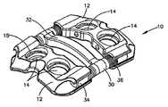
도 1은 메인 플레이트와 2개의 캐리지 부재를 구비하는 본 발명의 고정 시스템의 실시예의 사시도이다.1 is a perspective view of an embodiment of a fastening system of the present invention having a main plate and two carriage members.
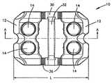
도 2는 도 1의 척추 고정 시스템의 평면도이다.2 is a plan view of the spinal fixation system of FIG.
도 3은 도 2의 A-A선을 통한 단면도이다.3 is a cross-sectional view taken along the line A-A of FIG.
도 4는 도 1의 고정 시스템의 캐리지 부재의 평면도이다.4 is a plan view of the carriage member of the securing system of FIG.
도 5는 도 4의 캐리지 부재의 정면도이다.5 is a front view of the carriage member of FIG.
도 6은 도 1의 고정 시스템의 플레이트의 평면도이다.6 is a plan view of a plate of the fastening system of FIG. 1.
도 7은 도 5의 플레이트의 정면도이다.7 is a front view of the plate of FIG. 5.
도 8은 도 5의 플레이트의 측면도이다.8 is a side view of the plate of FIG. 5.
도 9a는 도 5의 결합부의 확대도이다.9A is an enlarged view of the coupling part of FIG. 5.
도 9b는 도 9의 결합부의 확대도이다.9B is an enlarged view of the coupling unit of FIG. 9.
도 10은 캐리지 부재와 메인 플레이트 사이에서의 일방향 이동 운동을 도와 주도록 구성된 결합 클립의 평면도이다.10 is a plan view of the engagement clip configured to assist in one-way movement between the carriage member and the main plate.
도 11은 도 10의 C-C선을 따른 결합 클립의 단면도이다.11 is a cross-sectional view of the engagement clip along line C-C in FIG.
도 12는 도 10의 결합 클립의 측면도이다.12 is a side view of the coupling clip of FIG. 10.
도 13은 캐리지 부재 안에 설치될 때 은선으로 도시된 결합 클리브이 부분 사시도이다.Fig. 13 is a partial perspective view of the engaging cleave shown in hidden line when installed in the carriage member.
도 14는 캐리지 부재 안에 설치되고 메인 플레이트와 결합하는 결합 클립의 부분 사시도이다.14 is a partial perspective view of the engaging clip installed in the carriage member and engaging the main plate.
도 15a 내지 도 15c는 캐리지 부재의 결합부를 따라이동하는 결합 클립의 진행을 보여주는 확대도이다.15A to 15C are enlarged views showing the progress of the engaging clip moving along the engaging portion of the carriage member.
도 16은 본 발명의 고정 시스템의 다른 실시예의 사시도이다.16 is a perspective view of another embodiment of a fastening system of the present invention.
본 명세서에 개시된 시스템은 손상되거나 상처를 입은 디스크(또는 디스크의 일 부분)이 한 쌍의 척추골 사이로부터 제거되어 척추 융합 스페이서가 척추골 사이에 배치된 척추 융합 시술에 사용될 수 있다. 캐리지 부재들은 손상된 디스크 공간을 받치기 위해 손상된 척추골의 전방 부분에 부착될 수 있으며, 뼈 파스너들을 이용하여 척추골에 고정될 수 있다. 시스템은 인접한 척추골에 대한 스페이서의 융 합이 발생되는 고정에 이은 초기의 기간 동안 척추골이 정렬되도록 유지하는 기능을 할 수 있다. 시스템은 환자가 질이 나쁜 뼈를 가진 경우와 같이, 척추체(vertebral body) 속으로 스페이서가 과도하게 침강되는 것을 방지하기 위해 융합 스페이서에 가해지는 축 방향 척추 하중의 일부를 공유하는 기능도 가질 수 있다. 시스템은 수술-후 초기 기간 동안 스페이서가 디스크 공간으로부터 이탈되는 것을 방지하는 기능도 가질 수 있다.The systems disclosed herein can be used in spinal fusion procedures in which damaged or injured discs (or portions of discs) are removed from between a pair of vertebrae and spinal fusion spacers are placed between the vertebrae. Carriage members may be attached to the anterior portion of the damaged vertebrae to support the damaged disk space and may be secured to the vertebrae using bone fasteners. The system can function to keep the vertebrae aligned for an initial period of time following fixation in which fusion of spacers to adjacent vertebrae occurs. The system may also have the ability to share some of the axial spinal load applied to the fusion spacer to prevent the spacer from excessively settling into the vertebral body, such as when the patient has poor bone. . The system may also have the function of preventing spacers from deviating from the disk space during the post-operative initial period.
시스템은 단일-레벨(즉, 일-디스크) 또는 다수-레벨(즉, 다수 디스크) 융합 시술을 위해 사용될 수도 있다. 몇몇 실시예들은 척추체의 적어도 일부분이 제거되는 척추체 제거술(corpectomy procedure)에 사용될 수 있다. 단일 레벨 시스템은 대체로 두 쌍의 파스너 구멍들을 가질 수 있는 반면, 다수-레벨 플레이트들은 세 쌍 또는 그 이상의 쌍의 구멍들을 대체로 가질 수 있다.The system may be used for single-level (ie one-disk) or multi-level (ie multiple disk) fusion procedures. Some embodiments may be used in a corpectomy procedure in which at least a portion of the vertebral body is removed. Single-level systems can generally have two pairs of fastener holes, while multi-level plates can generally have three or more pairs of holes.
도 1은 메인 플레이트(30)와 캐리지 부재(12)를 구비하는 본 발명의 고정 시스템(10)의 일 실시예의 사시도를 도시한다. 고정 시스템(10)은 도 2에서는 평면도로 도시되고, 도 3에서는 측면도로 도시된다. 고정 시스템(10)은 세로축(A-A)과, 길이(L)를 가지며, 아래의 도 4 및 도 5와 관련하여 더 상세하게 논의되는, 적어도 하나의 캐리지 부재(12)를 구비할 수 있다. 캐리지 부재(12)는 뼈 파스너(미도시)의 적어도 일부를 수납하기 위한 적어도 하나의 파스너 구멍(14)을 구비할 수 있다. 고정 시스템(10)은 아래의 도 6 내지 도 9b와 관련하여 더 상세히 논의되는, 플레이트(30)를 역시 구비할 수 있다. 플레이트(30)는 본체부(32)와 본체부(32)로부터 확장하는 적어도 하나의 아암(34)을 구비할 수 있다. 아암들(34)은 캐리지 부 재(12)와 결합하기 위한 융기부(37)를 가진 결합부(36)를 구비할 수 있다.1 shows a perspective view of one embodiment of a
도 4 및 도 5를 참조하면, 각각의 캐리지 부재(12)는 뼈 파스너를 수납하기 위한 적어도 하나의 파스너 구멍(14)을 구비할 수 있으며, 이것은 캐리지 부재가 뼈 분절에 부착되는 것을 허용할 수 있다. 도 4 및 도 5에 도시된 실시예에 있어서, 각각의 캐리지 부재(12)는 2개의 파스너 구멍들(14)을 구비하고, 뼈 파스너들은 명확히 하기 위해 도면에서 제외되어 있다. 그러나, 캐리지 부재(12)는 하나, 3개, 또는 그 이상의 파스너 구멍들(14)을 필요에 따라 구비할 수 있음을 명백히 밝힌다. 파스너 구멍들(14)은 뼈 파스너가 역행하는 것을 방지하고, 그 상세한 내용, 재질 및 방법들은 Duong 등에 의해 2003. 9. 3.자로 출원된 미국 특허 출원 번호 10/653,164의 "고정 클립을 가진 뼈 플레이트"에 개시되고, 그 출원의 모든 내용은 인용에 의해 본 명세서에 명시적으로 합체되는, 고정 클립(15)에 조립될 수 있다.4 and 5, each
캐리지 부재(12)는 플레이트(30)의 적어도 일부를 수납하기 위한 적어도 하나의 채널(16)을 더 구비할 수 있으며, 그 결합은 아래에서 더 자세히 설명된다. 채널(16)은 구멍들(17A)(17B)을 구비할 수 있고, 캐리지 부재(12)의 본체를 관통하는 통로의 적어도 일부로 확장한다. 채널916)은 구멍들(17A)(17B) 사이에서 연장하는 절단부(cutaway portion)(20)를 가질 수 있다. 절단부(20)는 절단 높이(HC)를 가질 수 있다. 각각의 구멍(17A)(17B)은 플레이트(30)의 유사한 모양의 아암(34)을 수납하기 위해 대체로 원형의 모양일 수 있다. 각각의 구멍(17A)(17B)은 가장 자리(21A)(21B)를 역시 가질 수 있다. 채널(16)은 내부 표면(18)과 내부 표면(18)과 대향되게 놓여진 캐리지 부재(12)의 외부 표면(19)을 또한 가질 수 있다. 본 명세서에 개시된 실시예들에 있어서, 각각의 캐리지 부재(12)는 2개의 채널들(16)을 구비하며, 각각의 채널(16)은 2개의 구멍들(17)을 구비하고 있다. 그러나, 캐리지 부재는 다양한 숫자의 구멍들을 역시 가진 하나, 세개, 그 이상의 채널들을 구비할 수 있음을 명백히 하고자 한다. 그러한 변형들은 당업자라면 충분히 알 수 있을 것이다.The
캐리지 부재(12)는 상부 표면(13A)과 하부 표면(13B)을 역시 가질 수 있다. 하나 또는 모든 표면들(13A)(13B)은, 도 5에서 더 명백히 도시되어 있는 바와 같이, 캐리지 부재(12)의 길이를 따라 대체로 굴곡될 수 있다. 그러한 굴곡(curvature)은 캐리지 부재(12)가 요구되는 신체 부위 또는 뼈 분절과 보다 밀접하게 모양이 일치하도록 허용하는 데 도움이 될 수 있다.The
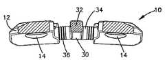
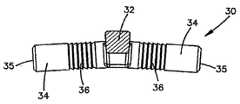
플레이트(30)의 실시예는 도 6 내지 도 9b에 도시된다. 플레이트(30)의 평면도는 도 6에 도시된다. 플레이트(30)의 정면도는 도 7에 도시된다. 플레이트(30)의 측면도는 도 8에 도시된다. 플레이트(30)의 결합부(36)의 확대도들은 도 9a 및 도 9b에 도시된다. 메인 플레이트(30)는 본체부(32)와, 적어도 하나의 아암(34), 및 세로축(B-B)을 구비할 수 있다. 아암(34)은 본체부(32)로부터 세로축(B-B)으로부터 떨어져 교차하도록 연장될 수 있으며, 캐리지 부재(12)의 채널(16) 내부에 적어도 부분적으로 수납되도록 크기와 치수가 결정될 수 있다. 아암들(34)은 끝단(35)을 역시 가질 수 있다.An embodiment of the
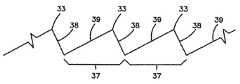
아암들(34)은 결합부(36)를 더 구비할 수 있고, 이것은 융기부(ridges)(37) 를 포함할 수 있다. 도 9a 및 도 9b에 더 상세히 도시된 바와 같이, 각각의 융기부(37)는 전방 표면(39)과 후방 표면(38), 및 그들 사이에 놓여진 정점(33)을 구비할 수 있다. 전방 표면(39)과 후방 표면(38)은 결합부(36)에 배치될 수 있고 전방 표면(39)과 후방 표면(38)은 결합부(36)의 길이를 따라 번갈아 나타난다. 따라서, 결과적인 결합부는 한 방향으로부터 연속적인 전방 표면들(39)과 다른 방향에서의 연속적인 후방 표면들(38)을 가진다.
결합부(36) 내부의 융기부들(37)은 실질적으로 동일한 크기일 수 있거나, 크기가 변화될 수 있다. 결합부(36)의 크기는 단일의 플레이트(30) 및/또는 단일의 고정 시스템(10)의 다른 아암(34)에 따라 변할 수 있다. 아암(34)은 하나 이상의 결합부(36)를 가질 수 있다. 각각의 정점(33)은 점 모양일 수 있거나, 실질적으로 라운드일 수 있다. 대체로 원형의 단면의 아암(34)을 위하여, 각각의 그러한 아암(34)의 최대 단면 직경은 정점(33)에 있을 수 있다.The
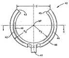
결합 클립(40)의 실시예가 도 10 내지 도 12에 도시된다. 대체로, 각각의 캐리지 부재(12)에는 플레이트(30)의 아암(34)과 캐리지 부재(12)의 채널들(16) 사이의 안전한 결합에 영향을 주기 위해 적어도 하나의 결합 클립(40)이 마련될 수 있다. 도 10 내지 도 12에 도시된 실시예에 있어서, 결합 클립(40)은 끝단(43)(45)을 각각 가지며, 그 끝단(43)(45) 사이의 간격(D)을 가진 아치형 갈퀴(prong)(42)를 구비한다. 간격(D)은 캐리지 부재(12)의 절단부(20)의 절단 높이(HC)와 실질적으로 동일할 수 있다.An embodiment of the
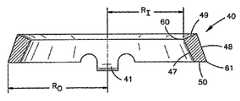
도 11은 도 10의 C-C선을 따른 결합 클립(40)의 단면도를 도시한다. 도 11에 도시된 바와 같이, 갈퀴들(42)(44)은 4개의 표면들(47)(48)(49)(50)을 가진 다각형 단면 모양일 수 있다. 아래에서 보다 상세히 설명되는 바와 같이, 내부 표면(47)은 융기부(37)의 전방 표면들(39)과 결합하고, 측면(49)은 융기부(37)의 후방 표면(38)과 결합한다. 또한, 내부 표면(47)과 측면(49)의 치수들은 각각 전방 표면들(39)과 후방 표면들(38)의 치수와 실질적으로 상응할 수 있다.FIG. 11 shows a cross-sectional view of the
결합 클립(40)은 중간 지점(MP)을 역시 가질 수 있다. 결합 클립(40)은 내경(RI)과 외경(RO)을 가질 수 있다. 내경(RI)은 내부 표면(47)과 외부 표면(49) 사이에서 중간 지점(MP)으로부터 가장 자리(60)까지의 거리에 의해 정의될 수 있다. 외경(RO)은 외부 표면(48)과 측면(50) 사이에서 중간 지점(MP)으로부터 가장 자리(61)까지의 거리에 의해 정의될 수 있다.The
캐리지 부재(12)에 대한 결합 클립(40)의 결합은 부분 확대 사시도인 도 13 및 도 14에 도시되어있다. 도 13에 도시된 바와 같이, 캐리지 부재(12)는 명확성을 위해 라인 형태로 도시되고, 결합 클립(40)이 채널(16)의 내부 표면(18)을 따라 ㅂ배치되도록 결합 클립(40)은 캐리지 부재(12)에 결합할 수 있다. 채널(16)은 그루브(50)와 결합 클립(40)의 적어도 일부를 수납하기 위해 내부 표면(18)을 따라 배치된 노치(notch)(미도시)를 구비할 수 있다. 갈퀴(42)(44)의 일부분은 그루브(50) 속으로 삽입될 수 있고, 유지 부재(retaining element)(41)는 노치 속으로 삽입될 수 있다. 바람직하게 결과는 결합 클립(40)은 캐리지 부재(12) 안에 고정되게 안착 되고, 유지 부재(41)는 캐리지 부재(12)에 대한 결합 클립(40)의 회전을 방지할 수 있도록 노치 속으로 삽입되는 것일 수 있다. 캐리지 부재(12)에 대한 결합 클립(40)의 결합은 명확성을 위해 캐리지 부재(12)의 일부를 도시한 도 14에 도시된다.The engagement of the
일반적으로, 적어도 하나의 캐리지 부재(12)는 플레이트(30), 특히 플레이트(30)의 결합부(들)(36)에서 결합한다. 결합 클립(40)은 결합부(36)의 융기부(37)와 결합할 수 있다. 클립(40)이 연속된 융기부(37)의 일 방향으로만 결합할 수 있도록 융기부들(37)이 배열되고, 결합 클립(40)은 구성될 수 있다. 그러한 관계의 효과는 캐리지 부재(12)가 플레이트(30)에 대하여 일방향으로 이동하는 것을 허용할 수 있는 것이다. 예시적 방법으로, 도 14에 도시된 캐리지 부재(12)와 플레이트(30)는 클립(40)이 현재 안착된 곳의 좌측으로 연속된 융기부(37)에 결합 클립(40)이 결합되는 그러한 방식으로 결합된다. 상술한 바와 같이, 결합 클립(40)이 제1 융기부(37A)로부터 제 융기부(37B)로 이동한 후, 결합 클립이 제1 융기부(37A)에 재결합 할 수 없도록-클립(40)이 갈퀴(42)(44)를 따라 다른 방향으로 이동할 수 있도록, 이러한 일 방향 관계는 융기부(37)의 표면들(38)(39)과 결합 클립(40)의 클립 갈퀴들(420(44)의 크기에 의해 얻어진다. 융기부들(37)은, 일방향 이동 장치의 상세 내용에 부가하여 그 상세 내용과 장점들이 Barrall 등에 의해 2004년 12일 1일자로 출원되고, 그 전체 개시내용이 인용에 의해 본 명세서에 명시적으로 합체되는 미국 특허 출원 번호 11/001,902의 "뼈 고정을 위한 일 방향 이동 시스템"에 개시된 "점진적 저항(progressive resistance)" 형태로 또한 배열될 수 있다.In general, the at least one
도 15a 내지 도 15c는 제1 융기부(37A)로부터 제2 융기부(37B)로 이동하는 결합 클립의 진행을 도시한다. 도 15a에 도시된 바와 같이, 결합 클립(40)은, 그 클립(40)의 측면(49)이 후방 표면(38A)과 접촉되고, 클립(40)의 내부 표면(47)이 전방 표면(39B)과 접촉된 상태로 융기부(37A)와 결합한다. 힘 "F"가 도시된 방향으로 작용하면, 클립(40)은 제2 융기부(37B)의 방향으로 전진하여 이동할 수 있다. 보다 상세하게는, (아래에서 논의되는 탄성 물질로 제작될 수 있는) 클립(40)의 전진은 갈퀴(42)(44)의 유연성에서 일어날 수 있으며, 끝단(43)(45)은 바깥으로 밀려 중간 지점(MP)으로부터 멀어질 수 있다. 클립(40)의 전진은 도 15b에 도시되고, 여기서 클립(40)은, 힘(F)의 추진력에 의해, 정점으로부터 떨어져 융기부(37c)로 이동한다. 이러한 과정 동안 내부 표면(47)은 전방 표면(39) 쪽으로 슬라이딩 결합할 수 있다. 만약, 가장 자리(60)가 전방 표면(39b)을 따라 정점(33b)을 지나가게 움직이도록 클립(40)이 충분히 밀착되면, 클립(40)은, 도 15c에 도시된 바와 같이, 제2 융기부(37b)에 스냅 결합될 수 있다. 그러나, 힘(F)는 클립(40)을 제2 융기부(37b)의 방향으로 움직이게 하는 데 충분하지만, 가장 자리(60)가 정점(33b)을 지나가도록 하는데 불충분하다면, 클립(40) 재질의 탄성 때문에 클립(40)은 연속적으로 압축되어, 도 15a에 도시된 위치로 복귀할 수 있음을 유의하는 것이 중요하다. 도 15c에 도시된 바와 같이, 클립(40)은 외과의사의 간섭이 없으면 융기부(37A)로 복귀하지 않을 수 있음을 인식하는 것 역시 중요하다. 도 15c에 도시된 위치로 클립(40)이 움직이기만 하면, 외과 의사의 개입 없이는 도 15a 및 도 15b의 위치로 역이동하지 않을 것이다.15A to 15C show the progression of the engaging clip moving from the
환자의 환부에서 인접한 척추골과 관련되는 척추에 적용되는 사용에 있어서, 외과 의사는 척추체 사이의 디스크의 적어도 일부분을 먼저 제거할 것이다. 스페이서 또는 다른 물질이 척추골 사이에 삽입될 수 있다. 외과 의사는 그 후 환자의 환부 근처에 시스템(10)을 배치시켜, 제1 캐리지 부재(12A)가 제1 척추골에 결합하도록 하고, 제2 캐리지 부재(12B)가 제2 척추골에 결합하도록 한다. 환자의 환부 주변에 시스템(10)을 배치시키는 단계 이전 또는 이후 그 어느 때에서, 외과 의사는 그 총 길이를 감소 또는 증가시키기 위해 시스템(10)을 손으로 압축 또는 확장할 수 있다. 시스템(10)이 위치되고 나면, 외과 의사는 파스너 구멍들(14)을 통하여 척추골 속으로 삽입된 뼈 파스너들(미도시)에 의해 캐리지 부재들(12A)(12B)을 그들 각각의 척추골에 고정되게 부착시킬 것이다. 외과 의사는 이 지점에서 수술 도중에도 시스템(10)을 손으로 압축 또는 확장할 수 있다. 외과 의사는 그 후 절개부위를 덮을 것이다.In applications applied to the vertebrae associated with adjacent vertebrae in the affected area of the patient, the surgeon will first remove at least a portion of the disc between the vertebral bodies. Spacers or other materials may be inserted between the vertebrae. The surgeon then places the
수술 후, 캐리지 부재(12)는 원위치에서 시스템(10)에 가해지는 힘에 대응하여 플레이트(30)에 상대적으로 이동할 수 있다. 예를 들어, 환자 속으로 이식된 후 크기 또는 힘이 흡수되거나 아니면 감소하는 추간 물질을 사용하는 경우, 척추골은 서로에 대해 가깝게 되도록 이동 및/또는 표류하는 경향이 있을 수 있다. 본 명세서에 개시된 시스템(10)은 결합 클립(40)이 플레이트(30) 위의 연속된 융기부들과 결합하는 것을 허용함으로써 캐리지 부재들(12)이 축방향으로 이동하는 것을 허용하여 그러한 힘들에 대응하는 것을 가능하게 한다. 그 결과는 시스템(10)이 원위치에서, 수술-후 힘들에 대응할 수 있을 정도로 충분히 압착할 수 있고, 및/또는 이 탈을 방지하도록 추간 물질에 충분한 압착을 유지하여 뼈 성장 및/또는 척추골 사이의 융합을 촉진할 수 있는 것이다.After surgery, the
시스템(10)은 일련의 다른 장치들 또는 그들과 결합하여 사용될 수 있음을 명백히 의도한다. 시스템(10)은 두개, 세개 또는 그 이상의 척추골과 함께, 연속하여 또는 비연속적으로 사용될 수 있음을 의도한다. 플레이트, 캐리지 부재들 및 다른 성분들의 상대 크기와 같은 시스템에 대한 다른 변형들은 당업자에 의해 평가될 수 있을 것이다.It is expressly intended that
전술한 방법과 장점들은 척추에 응용되는 것을 참조하여 설명되었지만, 본 명세서에 개시된 시스템(10)은 관절, 긴 뼈 골절과 같은 환자의 다른 부분에도 사용될 수 있음을 명백히 밝히고자 한다. 다른 외과적 사용은 당업자에 의해 평가될 것이다.Although the methods and advantages described above have been described with reference to applications in the spine, it will be apparent that the
결합 클립(40)은 가해지는 힘에 대응하여 갈퀴들(42)(44)이 분리되는 것을 허용할 수 있지만, 힘이 제거되면 그들의 최초 형태로 복귀하도록 하는 탄력적일 수 있는 물질로 제조될 수 있음을 이해할 것이다. 결합 클립(40)을 위한 적절한 재질의 예는 엘지로이(elgiloy)이다. 고정 클립(captive clip)(15)은 동일한 물질로 형성될 수 있다.The
본 명세서에 개시된 파스너, 플레이트, 캐리지 부재, 및 다른 부품들 각각은 양극 산화 처리될 수 있는 티타늄-알루미늄-니오븀과 같은 티타늄 합금으로 형성될 수 있다. 본 명세서에 개시된 플레이트 및 파스너 각각에 사용되는 물질은 약 4.52 gm/cc의 밀도, 약 105 GPa의 탄성 계수, 약 900 MPa의 극한 인장 강도, 및 약 800 MPa의 항복 강도를 가진 Ti-6Al-7Nb이다. 파스너들의 표면들은, 모든 날카로운 가장 자리가 최대 0.1mm로 분쇄되어 결함이 없을 수 있다.Each of the fasteners, plates, carriage members, and other components disclosed herein may be formed of a titanium alloy such as titanium-aluminum-niobium, which may be anodized. Materials used in each of the plates and fasteners disclosed herein include Ti-6Al-7Nb having a density of about 4.52 gm / cc, an elastic modulus of about 105 GPa, an ultimate tensile strength of about 900 MPa, and a yield strength of about 800 MPa. to be. The surfaces of the fasteners may be free of defects with all sharp edges crushed up to 0.1 mm.
도 16은 세로축을 가진 고정 시스템(110)의 대안적 실시예의 사시도이다. 캐리지 부재들(112)은 도 1 내지 도 15c를 참조하여 전술한 바와 같은 캐리지 부재들(12)과 실질적으로 유사할 수 있다. 본 실시예에 있어서, 플레이트(130)는 아암(34)의 결합부(36)와 실질적으로 유사한 결합부(136)를 가지며 축방향으로 연장하는 아암(134)을 구비할 수 있다. 결합 클립(40)은 캐리지 부재들(112)의 채널들(116) 내부에 배치될 수 있다. 도 16에 도시된 실시예와 전술한 실시예들 사이의 중대한 차이점은 본체부(132)가 I-모양의 바(bar)의 형태로 되어 있기 보다는 신체 표면의 모양과 일치하도록 구성된 가늘고 긴 플레이트 형태라는 것이다. 본체부(132)에는 적어도 하나의 윈도우(150)가 마련될 수 있으며, 도 15의 실시예는 3개의 그러한 윈도우(150)가 도시되어 있다. 각각의 윈도우(150)에는 윈도우(150) 안에서 횡방향으로 슬라이딩 할 수 있는 중간 캐리지 블록(160)이 마련된다. 각각의 캐리지 블록(160)은 뼈 파스너(미도시)의 적어도 일부와 결합하기 위해 그안에 배치된 고정 클립(164)을 가진 파스너 구멍(162)을 가질 수 있다. 윈도우(150)와 캐리지 블록(160) 사이의 접촉 표면들은 캐리지(160)가 윈도우(150)에 조립된 후 느슨해지는 것을 방지하기 위해 꼭들어 맞도록 되어 있다. 도 16에 도시된 실시예는 척추 기둥을 따라 2개보다 많은 연속된 척추골의 이동 가능한 고정을 수행할 수 있다. 중간 캐리지 부재, 및 다중-레벨 고정의 더 상세한 내용, 재질, 밀 방법들은 2004년 9월 2일자로 Suh 등에 의해 출원되고, 그 전체 내용이 인용에 의해 본 명세 서에 명백히 합체되는 미국 특허 출원 10/932,392의 "트랙-플레이트 캐리지 시스템"에 개시되어 있다.16 is a perspective view of an alternative embodiment of the securing
전술한 설명들과 실례들은 본 발명의 원칙들을 사용하여 설계 및 조립될 수 있는 이동 플레이트들의 구성의 예로서 제공되었다는 사실을 유의해야 한다. 이러한 예들은 개시된 특징들의 하나 또는 그 이상을 채택하고 있는 고정 시스템이 특정 환자의 요구를 위해 바람직하거나 필요하게 생성될 수 있음을 제한하지 않는 것을 당업자는 이해해야 한다. 따라서, 개시된 특징들은 속성상 "기준"이다.It should be noted that the foregoing descriptions and examples have been provided as examples of the configuration of moving plates that can be designed and assembled using the principles of the present invention. Those skilled in the art should understand that these examples do not limit that a fixation system employing one or more of the disclosed features may be created as desired or necessary for the needs of a particular patient. Thus, the disclosed features are "criteria" in nature.
이러한 문언의 설명은 청구된 발명의 최적 실시예를 묘사하고, 특허청구범위에 열거된 구성요소들의 예를 제시함으로써 당업자가 그것을 제조할 수 있도록 청구된 발명을 개시한다. 본 발명의 특허 가능한 범위는 특허청구범위 그 자체에 의해 정의되며, 당업자에게 일어날 수 있는 다른 예시들도 포함할 수 있다. 본 출원의 출원일 전 또는 후 중 어느 하나에 이용할 수 있는 그러한 다른 예들은 그들이 특허청구범위의 문언적 용어와 다르지 않는 구조적 구성요소를 가지거나, 그들이 특허청구범위의 문언적 용어로부터 비실질적인 차이를 가진 균등한 구조적 구성요소들을 가지면 본 발명의 특허청구범위의 범위 내에 있음을 의도한다.The description of this word describes the best embodiment of the claimed invention and discloses the claimed invention so that those skilled in the art can make it by presenting examples of the components listed in the claims. The patentable scope of the invention is defined by the claims themselves, and may include other examples that occur to those skilled in the art. Such other examples that may be used either before or after the filing date of the present application have structural elements that do not differ from the literal terms of the claims, or that they have an impractical difference from the literal terms of the claims. Having equivalent structural components is intended to be within the scope of the claims of the present invention.
본 발명은 특정의 실시예들을 참조하여 본 명세서에 도시되고 개시되었지만, 본 발명의 정신 및 범위를 벗어나지 않고, 개시된 실시예들에 대해 형태, 구조, 배열, 비례, 재료, 및 성분, 아니면 특정의 환경 및 작동 조건에 특히 맞도록 개조되어 실제 사용되는 다양한 부가, 대체 또는 변형들이 가능하다는 것을 이해해야 한 다. 따라서, 본 명세서에 개시된 실시예들은 본 발명의 원칙의 예시에 불과한 점이 이해되어야 한다. 당업자에 의해 이루어질 수 있는 다양한 다른 변형예들은 본 발명의 원칙들을 구체화할 것이며 본 발명의 정신 및 범위 내에 머물게 될 것이다.While the present invention has been shown and described herein with reference to specific embodiments, it is to be understood that the forms, structures, arrangements, proportions, materials, and components, or specific embodiments thereof, may be modified with respect to the disclosed embodiments without departing from the spirit and scope of the invention. It should be understood that various additions, substitutions, or modifications are possible which have been adapted specifically to the environment and operating conditions to be used in practice. Accordingly, it should be understood that the embodiments disclosed herein are merely illustrative of the principles of the present invention. Various other modifications that can be made by those skilled in the art will embody the principles of the invention and will remain within the spirit and scope of the invention.
Claims (20)
Translated fromKoreanApplications Claiming Priority (2)
| Application Number | Priority Date | Filing Date | Title |
|---|---|---|---|
| US11/078,802 | 2005-03-11 | ||
| US11/078,802US7479143B2 (en) | 2005-03-11 | 2005-03-11 | Unidirectional fixation device |
Publications (1)
| Publication Number | Publication Date |
|---|---|
| KR20070117608Atrue KR20070117608A (en) | 2007-12-12 |
Family
ID=36579599
Family Applications (1)
| Application Number | Title | Priority Date | Filing Date |
|---|---|---|---|
| KR1020077021948AAbandonedKR20070117608A (en) | 2005-03-11 | 2006-03-03 | Unidirectional fixture |
Country Status (12)
| Country | Link |
|---|---|
| US (1) | US7479143B2 (en) |
| EP (1) | EP1871256A1 (en) |
| JP (1) | JP4940228B2 (en) |
| KR (1) | KR20070117608A (en) |
| CN (1) | CN100512771C (en) |
| AU (1) | AU2006223600A1 (en) |
| BR (1) | BRPI0609001A2 (en) |
| CA (1) | CA2600742A1 (en) |
| CO (1) | CO6190590A2 (en) |
| NZ (1) | NZ561415A (en) |
| TW (1) | TWI324917B (en) |
| WO (1) | WO2006098908A1 (en) |
Cited By (1)
| Publication number | Priority date | Publication date | Assignee | Title |
|---|---|---|---|---|
| KR101886341B1 (en)* | 2017-06-14 | 2018-08-07 | 인하대학교 산학협력단 | Segmented plate assembly for remedy of fracture bone |
Families Citing this family (30)
| Publication number | Priority date | Publication date | Assignee | Title |
|---|---|---|---|---|
| US7621942B2 (en)* | 2005-03-21 | 2009-11-24 | Zimmer Spine, Inc. | Variable geometry occipital fixation plate |
| US7993380B2 (en)* | 2005-03-31 | 2011-08-09 | Alphatel Spine, Inc. | Active compression orthopedic plate system and method for using the same |
| US8070749B2 (en) | 2005-05-12 | 2011-12-06 | Stern Joseph D | Revisable anterior cervical plating system |
| US20070123881A1 (en)* | 2005-10-26 | 2007-05-31 | Ralph James D | Off-set bone plates |
| WO2007098188A2 (en)* | 2006-02-21 | 2007-08-30 | Life Spine, Inc. | Structure for joining and retaining multi-part orthopedic implants |
| US7699874B2 (en)* | 2006-03-01 | 2010-04-20 | Warsaw Orthopedic, Inc. | Low profile spinal rod connector system |
| US7901433B2 (en)* | 2006-10-04 | 2011-03-08 | Zimmer Spine, Inc. | Occipito-cervical stabilization system and method |
| US8262710B2 (en) | 2006-10-24 | 2012-09-11 | Aesculap Implant Systems, Llc | Dynamic stabilization device for anterior lower lumbar vertebral fusion |
| US20080147124A1 (en)* | 2006-10-31 | 2008-06-19 | Haidukewych George J | Bone plate system with slidable compression holes |
| US8206390B2 (en)* | 2006-11-02 | 2012-06-26 | Warsaw Orthopedic, Inc. | Uni-directional ratcheting bone plate assembly |
| US8147527B2 (en)* | 2006-11-28 | 2012-04-03 | Zimmer Spine, Inc. | Adjustable occipital plate |
| US8246662B2 (en)* | 2006-12-27 | 2012-08-21 | Zimmer Spine, Inc. | Modular occipital plate |
| US8636737B2 (en)* | 2006-12-27 | 2014-01-28 | Zimmer Spine, Inc. | Modular occipital plate |
| US8388663B2 (en) | 2007-09-13 | 2013-03-05 | Stryker Spine | Dynamic cervical plate |
| WO2009055537A1 (en) | 2007-10-23 | 2009-04-30 | K2M, Inc. | Dynamic cervical plate |
| EP2224868B1 (en) | 2007-11-21 | 2014-07-30 | Globus Medical, Inc. | Cervical spine stabilization system with extendable plates |
| US20090210008A1 (en)* | 2008-02-20 | 2009-08-20 | Life Spine, Inc. | Modular spine plate with projection and socket interface |
| WO2010025405A1 (en)* | 2008-08-29 | 2010-03-04 | Life Spine, Inc. | Single-sided dynamic spine plates |
| JP5461083B2 (en)* | 2009-07-01 | 2014-04-02 | 京セラメディカル株式会社 | Osteosynthesis surgical instrument |
| US8808333B2 (en) | 2009-07-06 | 2014-08-19 | Zimmer Gmbh | Periprosthetic bone plates |
| US8834532B2 (en) | 2009-07-07 | 2014-09-16 | Zimmer Gmbh | Plate for the treatment of bone fractures |
| US10342583B2 (en) | 2010-10-01 | 2019-07-09 | K2M, Inc. | Dynamic plate with inserts |
| US11123117B1 (en) | 2011-11-01 | 2021-09-21 | Nuvasive, Inc. | Surgical fixation system and related methods |
| US9579128B2 (en) | 2013-07-19 | 2017-02-28 | K2M, Inc. | Translational plate and compressor instrument |
| US9468479B2 (en) | 2013-09-06 | 2016-10-18 | Cardinal Health 247, Inc. | Bone plate |
| US11253299B2 (en) | 2013-10-28 | 2022-02-22 | Jace Medical, Llc | Orthopaedic fixation devices, systems and methods |
| US9681903B2 (en) | 2013-11-15 | 2017-06-20 | K2M, Inc. | Clip for dynamic spinal plate |
| WO2016029008A1 (en) | 2014-08-20 | 2016-02-25 | Jace Medical, Llc | Implant positioning devices and methods |
| US10130358B2 (en) | 2015-10-07 | 2018-11-20 | Arthrex, Inc. | Devices for controlling the unloading of superelastic and shape memory orthopedic implants |
| TWI736417B (en)* | 2020-09-15 | 2021-08-11 | 財團法人工業技術研究院 | Flexible bone fixation device |
Family Cites Families (14)
| Publication number | Priority date | Publication date | Assignee | Title |
|---|---|---|---|---|
| US3385299A (en)* | 1965-10-23 | 1968-05-28 | New Res And Dev Lab Inc | Wound clip |
| DE2621175C3 (en) | 1976-05-11 | 1979-04-19 | Erhard Dr. 1000 Berlin Westerhoff | Device for the gradual lengthening of limbs |
| GB8718708D0 (en)* | 1987-08-07 | 1987-09-16 | Mehdian S M H | Apparatus for treatment of spinal disorders |
| US5470333A (en)* | 1993-03-11 | 1995-11-28 | Danek Medical, Inc. | System for stabilizing the cervical and the lumbar region of the spine |
| US5616142A (en)* | 1994-07-20 | 1997-04-01 | Yuan; Hansen A. | Vertebral auxiliary fixation device |
| US5827286A (en) | 1997-02-14 | 1998-10-27 | Incavo; Stephen J. | Incrementally adjustable tibial osteotomy fixation device and method |
| US6513887B2 (en)* | 2001-01-05 | 2003-02-04 | Coin Acceptors, Inc. | Spring clip retainer for vending machine storage compartments |
| JP4283665B2 (en)* | 2001-06-04 | 2009-06-24 | ウォーソー・オーソペディック・インコーポレーテッド | Dynamic plate for anterior cervical spine with movable segments |
| US7044952B2 (en) | 2001-06-06 | 2006-05-16 | Sdgi Holdings, Inc. | Dynamic multilock anterior cervical plate system having non-detachably fastened and moveable segments |
| US6932820B2 (en)* | 2002-01-08 | 2005-08-23 | Said G. Osman | Uni-directional dynamic spinal fixation device |
| US20040019353A1 (en)* | 2002-02-01 | 2004-01-29 | Freid James M. | Spinal plate system for stabilizing a portion of a spine |
| US6602257B1 (en)* | 2002-06-24 | 2003-08-05 | Jeffrey J. Thramann | Cervical plate |
| WO2004008978A1 (en) | 2002-07-24 | 2004-01-29 | Nas Spine, Inc. | Compressible fixation apparatus for spinal surgery |
| US20050049595A1 (en) | 2003-09-03 | 2005-03-03 | Suh Sean S. | Track-plate carriage system |
- 2005
- 2005-03-11USUS11/078,802patent/US7479143B2/enactiveActive
- 2006
- 2006-03-03AUAU2006223600Apatent/AU2006223600A1/ennot_activeAbandoned
- 2006-03-03NZNZ561415Apatent/NZ561415A/enunknown
- 2006-03-03KRKR1020077021948Apatent/KR20070117608A/ennot_activeAbandoned
- 2006-03-03BRBRPI0609001Apatent/BRPI0609001A2/ennot_activeIP Right Cessation
- 2006-03-03WOPCT/US2006/007661patent/WO2006098908A1/enactiveApplication Filing
- 2006-03-03JPJP2008500777Apatent/JP4940228B2/ennot_activeExpired - Fee Related
- 2006-03-03CACA002600742Apatent/CA2600742A1/ennot_activeAbandoned
- 2006-03-03EPEP06736906Apatent/EP1871256A1/ennot_activeWithdrawn
- 2006-03-03CNCNB2006800152633Apatent/CN100512771C/ennot_activeExpired - Fee Related
- 2006-03-10TWTW095108244Apatent/TWI324917B/ennot_activeIP Right Cessation
- 2007
- 2007-10-03COCO07103465Apatent/CO6190590A2/ennot_activeApplication Discontinuation
Cited By (1)
| Publication number | Priority date | Publication date | Assignee | Title |
|---|---|---|---|---|
| KR101886341B1 (en)* | 2017-06-14 | 2018-08-07 | 인하대학교 산학협력단 | Segmented plate assembly for remedy of fracture bone |
Also Published As
| Publication number | Publication date |
|---|---|
| JP4940228B2 (en) | 2012-05-30 |
| EP1871256A1 (en) | 2008-01-02 |
| JP2008532628A (en) | 2008-08-21 |
| US7479143B2 (en) | 2009-01-20 |
| NZ561415A (en) | 2010-08-27 |
| CA2600742A1 (en) | 2006-09-21 |
| US20060217724A1 (en) | 2006-09-28 |
| CN101170956A (en) | 2008-04-30 |
| AU2006223600A1 (en) | 2006-09-21 |
| CN100512771C (en) | 2009-07-15 |
| TW200701938A (en) | 2007-01-16 |
| CO6190590A2 (en) | 2010-08-19 |
| TWI324917B (en) | 2010-05-21 |
| WO2006098908A1 (en) | 2006-09-21 |
| BRPI0609001A2 (en) | 2016-11-08 |
Similar Documents
| Publication | Publication Date | Title |
|---|---|---|
| KR20070117608A (en) | Unidirectional fixture | |
| US8641765B2 (en) | Posterior spinal implant system | |
| JP7193241B2 (en) | spine implant system | |
| AU2002242022B2 (en) | Spinal implant with attached ligament | |
| US9925064B2 (en) | Intervertebral fusion implant | |
| US8323342B2 (en) | Intervertebral implant | |
| US7112222B2 (en) | Anterior lumbar interbody fusion cage with locking plate | |
| KR20080002812A (en) | Moving plate with spring beam retainer | |
| EP2328495B1 (en) | Intervertebral fusion implant | |
| US7819903B2 (en) | Spinal fixation plate | |
| US9005256B2 (en) | Vertical inline plate | |
| AU2008230056A1 (en) | Slidable bone plate system | |
| US20080269806A1 (en) | Prostheses for locking an artificial disc in an intervertebral disc space | |
| KR20080025035A (en) | Moving scissor plate fixing system | |
| AU2002242022A1 (en) | Spinal implant with attached ligament | |
| EP3024418A1 (en) | Fusion plate with directional holes and implant systems employing the same | |
| JP2013523348A (en) | Intervertebral implant | |
| US8574298B2 (en) | Spinal implant | |
| CN112535555B (en) | Lumbar interbody fusion fixation device | |
| AU2003245119A1 (en) | Spinal implant |
Legal Events
| Date | Code | Title | Description |
|---|---|---|---|
| PA0105 | International application | Patent event date:20070921 Patent event code:PA01051R01D Comment text:International Patent Application | |
| PG1501 | Laying open of application | ||
| A201 | Request for examination | ||
| PA0201 | Request for examination | Patent event code:PA02012R01D Patent event date:20110208 Comment text:Request for Examination of Application | |
| E902 | Notification of reason for refusal | ||
| PE0902 | Notice of grounds for rejection | Comment text:Notification of reason for refusal Patent event date:20120724 Patent event code:PE09021S01D | |
| E90F | Notification of reason for final refusal | ||
| PE0902 | Notice of grounds for rejection | Comment text:Final Notice of Reason for Refusal Patent event date:20130122 Patent event code:PE09021S02D | |
| E701 | Decision to grant or registration of patent right | ||
| PE0701 | Decision of registration | Patent event code:PE07011S01D Comment text:Decision to Grant Registration Patent event date:20130516 | |
| PC1904 | Unpaid initial registration fee |