KR20070114842A - Dot pattern - Google Patents
Dot patternDownload PDFInfo
- Publication number
- KR20070114842A KR20070114842AKR20077024724AKR20077024724AKR20070114842AKR 20070114842 AKR20070114842 AKR 20070114842AKR 20077024724 AKR20077024724 AKR 20077024724AKR 20077024724 AKR20077024724 AKR 20077024724AKR 20070114842 AKR20070114842 AKR 20070114842A
- Authority
- KR
- South Korea
- Prior art keywords
- dot
- information
- block
- dots
- virtual
- Prior art date
- Legal status (The legal status is an assumption and is not a legal conclusion. Google has not performed a legal analysis and makes no representation as to the accuracy of the status listed.)
- Granted
Links
Images


Classifications
- G—PHYSICS
- G06—COMPUTING OR CALCULATING; COUNTING
- G06K—GRAPHICAL DATA READING; PRESENTATION OF DATA; RECORD CARRIERS; HANDLING RECORD CARRIERS
- G06K19/00—Record carriers for use with machines and with at least a part designed to carry digital markings
- G06K19/06—Record carriers for use with machines and with at least a part designed to carry digital markings characterised by the kind of the digital marking, e.g. shape, nature, code
- G06K19/06009—Record carriers for use with machines and with at least a part designed to carry digital markings characterised by the kind of the digital marking, e.g. shape, nature, code with optically detectable marking
- G06K19/06037—Record carriers for use with machines and with at least a part designed to carry digital markings characterised by the kind of the digital marking, e.g. shape, nature, code with optically detectable marking multi-dimensional coding
- G—PHYSICS
- G06—COMPUTING OR CALCULATING; COUNTING
- G06F—ELECTRIC DIGITAL DATA PROCESSING
- G06F3/00—Input arrangements for transferring data to be processed into a form capable of being handled by the computer; Output arrangements for transferring data from processing unit to output unit, e.g. interface arrangements
- G06F3/01—Input arrangements or combined input and output arrangements for interaction between user and computer
- G06F3/03—Arrangements for converting the position or the displacement of a member into a coded form
- G06F3/033—Pointing devices displaced or positioned by the user, e.g. mice, trackballs, pens or joysticks; Accessories therefor
- G06F3/0354—Pointing devices displaced or positioned by the user, e.g. mice, trackballs, pens or joysticks; Accessories therefor with detection of 2D relative movements between the device, or an operating part thereof, and a plane or surface, e.g. 2D mice, trackballs, pens or pucks
- G06F3/03545—Pens or stylus
- G—PHYSICS
- G06—COMPUTING OR CALCULATING; COUNTING
- G06K—GRAPHICAL DATA READING; PRESENTATION OF DATA; RECORD CARRIERS; HANDLING RECORD CARRIERS
- G06K19/00—Record carriers for use with machines and with at least a part designed to carry digital markings
- G06K19/06—Record carriers for use with machines and with at least a part designed to carry digital markings characterised by the kind of the digital marking, e.g. shape, nature, code
- G—PHYSICS
- G06—COMPUTING OR CALCULATING; COUNTING
- G06K—GRAPHICAL DATA READING; PRESENTATION OF DATA; RECORD CARRIERS; HANDLING RECORD CARRIERS
- G06K7/00—Methods or arrangements for sensing record carriers, e.g. for reading patterns
- G06K7/10—Methods or arrangements for sensing record carriers, e.g. for reading patterns by electromagnetic radiation, e.g. optical sensing; by corpuscular radiation
Landscapes
- Engineering & Computer Science (AREA)
- Theoretical Computer Science (AREA)
- Physics & Mathematics (AREA)
- General Physics & Mathematics (AREA)
- General Engineering & Computer Science (AREA)
- Human Computer Interaction (AREA)
- General Health & Medical Sciences (AREA)
- Electromagnetism (AREA)
- Health & Medical Sciences (AREA)
- Toxicology (AREA)
- Artificial Intelligence (AREA)
- Computer Vision & Pattern Recognition (AREA)
- Image Processing (AREA)
- Editing Of Facsimile Originals (AREA)
- Image Analysis (AREA)
- Processing Or Creating Images (AREA)
Abstract
Translated fromKoreanDescription
Translated fromKorean본 발명은, 인쇄물 등에 형성된 도트 패턴 정보를 광학적으로 독취함으로써, 여러 가지 정보나 프로그램을 입출력시키는 도트 패턴을 이용한 정보 입출력 방법에 관한 것으로서, 특히 도트로 구성되는 블록의 방향을 판정할 수 있는 기술에 관한 것이다.BACKGROUND OF THE
종래부터, 인쇄물 등에 인쇄된 바코드를 독취하여 음성 등의 정보를 출력시키는 정보 출력 방법이 제안되어 있다. 예를 들면, 미리 기억 수단에 부여한 키 정보에 일치하는 정보를 기억하여 두고, 바코드 리더로 독취한 키로부터 검색하여 정보 등을 출력하는 방법이 제안되어 있다. 또한, 많은 정보나 프로그램을 출력할 수 있도록, 미세한 도트를 소정의 법칙으로 정렬한 도트 패턴을 생성하고, 인쇄물 등에 인쇄한 도트 패턴을 카메라에 의하여 화상 데이터로서 읽어 들여, 디지털화하여 음성 정보를 출력시키는 기술도 제안되어 있다.Background Art Conventionally, an information output method for reading a bar code printed on a printed matter or the like and outputting information such as voice has been proposed. For example, a method of storing information corresponding to key information previously given to the storage means, searching from a key read by a bar code reader, and outputting information or the like has been proposed. Further, in order to output a lot of information or programs, a dot pattern in which fine dots are aligned according to a predetermined law is generated, and the dot pattern printed on a printed matter or the like is read by the camera as image data and digitized to output audio information. Techniques have also been proposed.
그러나, 상기 종래의 바코드에 의하여 음성 등을 출력시키는 방법은, 인쇄물 등에 인쇄된 바코드가 눈에 거슬리는 문제를 가지고 있었다. 또한, 바코드가 크고, 지면의 일부를 점유하기 때문에, 일부분의 문장 또는 사진, 그림, 그래픽의 화상 안에 등장하는 의미를 갖는 캐릭터나 대상물 마다 알기 쉽고 수많은 바코드를 할당 하는 것은 레이아웃(layout) 상 불가능하다는 문제를 가지고 있었다.However, the conventional method of outputting a voice or the like by a bar code has a problem that the bar code printed on the printed matter is unobtrusive. In addition, since the barcode is large and occupies a part of the page, it is difficult to assign a large number of barcodes to each character or object having a meaning appearing in a part of a sentence or a picture, picture or graphic image. Had a problem.
따라서, 본 발명자는, 아래의 특허 문헌에 나타낸 바와 같이, 인쇄면에 영향을 주는 일 없이 많은 데이터를 격납할 수 있는 전혀 새로운 도트 패턴을 제안해 오고 있다.Therefore, the present inventor has proposed an entirely new dot pattern that can store a lot of data without affecting the printing surface, as shown in the following patent document.
특허문헌 1 : 국제공개번호 WO/2004/084125호 공개공보Patent Document 1: International Publication No. WO / 2004/084125
특허 문헌 2 : 국제출원번호 PCT/JP2004/019427호 공개공보Patent Document 2: International Publication No. PCT / JP2004 / 019427
이와 같은 발명자에 의한 선행 기술(특허 문헌 1, 2)에 있어서, 본 발명자는 키 도트를 설치하여 데이터의 방향(블록의 방향)과 블록의 영역을 정의하는 것을 제안하고 있다. 이와 같이 블록의 방향이 파악됨으로써, 블록으로 정의된 정보를 그 방향마다 다른 의미로 할 수 있기 때문에, 다양한 정보를 격납할 수 있는 본 발명자의 독자적이고 독창적인 도트 패턴을 제안하고 있다.In the prior art by the inventors (
그러나, 이 키 도트에 의하여 블록의 방향을 정의하는 기술은, 키 도트를 배치하기 위한 개소에는 정보 도트를 배치할 수 없기 때문에, 블록의 정보량이 제한되고 또한 키 도트를 탐색하기 위한 알고리즘이 복잡화하여 계산 에 시간을 요하며 또한 키 도트의 주변 영역의 착안량이 크기 때문에, 프래임 버퍼(frame buffer)의 해상도도 필요하다는 극복하여야 할 과제가 있는 것이 본 발명자에 의하여 새롭게 지적되었다.However, in the technique of defining the direction of the block by the key dot, since the information dot cannot be placed at the location for placing the key dot, the information amount of the block is limited and the algorithm for searching for the key dot is complicated. It is newly pointed out by the present inventors that there is a problem to be overcome, which requires time for calculation and a large amount of attention in the peripheral area of the key dot, so that the resolution of the frame buffer is also required.
본 발명은, 이러한 점을 감안한 것으로서, 블록의 방향을 정의하기 위하여 정보 도트를 희생하는 일이 없이, 이 탐색의 알고리즘이 간단하고 또한 낮은 해상도의 프래임 버퍼에서도 독취할 수 있는, 키 도트를 대신할 디렉션 도트의 기술을 실현하는 것을 과제로 한다.In view of the above, the present invention replaces the key dot, which can be read in a simple and low resolution frame buffer without sacrificing information dots to define the direction of the block. It is a task to realize the technology of the direction dot.
상기 과제를 해결하기 위하여, 본 발명에서는, 이하의 수단을 채용했다.In order to solve the said subject, the following means were employ | adopted in this invention.
본 발명의 청구항 1은, 소정의 정보 도트를 배치하는 블록 영역 내에 복수의 기준점을 설치하고, 상기 기준점으로부터 정의되는 복수의 가상 기준점(예를 들면 격자 영역의 중심점)을 배치하고, 상기 가상 기준점으로부터의 거리와 방향으로 정보가 정의되는 정보 도트를 배치하고, 상기 적어도 소정 위치의 정보 도트를, 상기 가상 기준점으로부터의 방향으로 상기 블록의 방향을 나타내는 디렉션 도트로 한 도트 패턴이다.
즉, 본 발명에서는, 지면 등의 매체 상에 소정의 규칙(예를 들면 삼각형이나 사각형 또한 그 이상의 다각형의 정점이나, 그것들의 변의 소정 간격 마다 등)을 토대로 기준점을 배치한다. 그리고 그 배치된 복수의 기준점으로부터 어떤 규칙을 토대로 하여 가상 기준점을 설정한다. 여기에서 어떤 규칙이란, 예를 들면, 상기 다각형의 정점 끼리를 연결한 선의 교점을 가상 기준점으로 하는 경우이다. 그리고, 이 가상 기준점을 시점으로 한 벡터의 종점에 도트를 배치한다. 이 도트는 정보를 정의하는 정보 도트로서 기능을 하는데, 적어도 블록 중 한 개의 정보 도트의 방향을 기타 도트와 다르게 함으로써 상기 블록의 방향이나 크기를 나타내는 디렉션 도트로 할 수 있다. 여기에서 방향이란 상기 디렉션 도트가 상기 가상 기준점으로부터 상방향의 벡터 종점에 배치되어 있는 경우에는, 이 디렉션 도트가 소속하는 블록은 상향임을 식별할 수 있다.That is, in the present invention, a reference point is arranged on a medium such as the ground based on a predetermined rule (for example, a vertex of a triangle or a quadrangle or more polygons, or at predetermined intervals of the sides thereof). Then, a virtual reference point is set based on a rule from the arranged plurality of reference points. Here, a certain rule is a case where the intersection point of the line which connected the vertices of the said polygon is made into a virtual reference point, for example. And a dot is arrange | positioned at the end point of the vector which made this virtual reference point the starting point. This dot functions as an information dot defining information, and can be a direction dot indicating the direction or size of the block by changing the direction of at least one information dot of the block from other dots. Here, the direction may identify that the direction dot is a block to which the direction dot belongs when the direction dot is disposed at the vector end point upward from the virtual reference point.
또한, 크기에 관하여, 복수의 블록이 연결되어 있는 경우에, 상기 디렉션 도트의 배치 위치의 반복 패턴에 의하여 블록의 크기를 식별할 수 있다. 예를 들면, 디렉션 도트가 블록 중심에 배치되어 있는 경우, 상기 디렉션 도트가 상하 좌우 방향으로 3 격자 영역마다 나타나고 있으면, 상기 블록은 3×3 격자 영역의 크기를 가지는 것을 식별할 수 있다.In addition, with respect to the size, when a plurality of blocks are connected, the size of the block can be identified by a repeating pattern of the arrangement position of the direction dot. For example, when the direction dot is disposed at the center of the block, if the direction dot appears every three grid areas in the up, down, left, and right directions, it may be identified that the block has a size of 3 × 3 grid areas.
이와 같이, 정보 도트를 블록의 방향을 나타내는 디렉션 도트와 겸용함으로써, 상기 디렉션 도트 자체에도 정보를 의미 부여하면서, 블록의 방향을 정의할 수 있기 때문에, 정보 도트를 희생하지 않고, 블록의 방향을 정의할 수 있다.In this way, by using the information dot as a direction dot indicating the direction of the block, the direction of the block can be defined while giving information to the direction dot itself. Therefore, the direction of the block is defined without sacrificing the information dot. can do.
또한, 이러한 블록 내의 디렉션 도트를 배치하는 사각형 영역을, 몇 개의 기준점을 중심으로 90도씩 회전시켰을 때, 즉, 90도, 180도, 270도 회전시켰을 때에 동일한 위치 관계가 재현되지 않도록 배치함으로써, 탐색 알고리즘이 간단하고 또한 낮은 해상도의 프래임 버퍼에서도 독취가 가능해진다.In addition, the search is made by arranging the rectangular area in which the direction dot is arranged in such a block so that the same positional relationship is not reproduced when it is rotated by 90 degrees about several reference points, that is, when rotated by 90, 180, or 270 degrees. The algorithm is simple and can be read in low resolution frame buffers.
이러한 도트 패턴은, 컴퓨터 등의 정보처리장치에 프로그래밍함으로써, 상기 프로그램을 토대로 프린터 등에서 인쇄 출력함으로써 지면 등 매체 상에 생성할 수 있다.Such a dot pattern can be generated on a medium such as paper by programming to an information processing apparatus such as a computer and printing the output by a printer or the like based on the program.
또한, 이와 같은 매체면 상의 도트 패턴은, 광학 독취 수단을 사용하여 화상 데이터로서 독취하고, 상기 화상 데이터를 해석하여 도트 상호 간의 위치와 거리를 해석함으로써 기준점, 가상 기준점, 디렉션 도트, 정보 도트로서 인식할 수 있다.In addition, such dot patterns on the surface of the medium are read as image data using optical reading means, and the image data are interpreted to analyze the position and distance between the dots to be recognized as reference points, virtual reference points, direction dots, and information dots. can do.
본 발명의 청구항 2는, 상기 기준점은, 상기 블록의 영역 내에서, 상하 또는 좌우 방향으로 등간격으로 배치된 격자점이며, 상기 4개 격자점의 중심을 가상 벡터 시점으로 하고, 이 가상 벡터 시점을 기준으로 하고, 상기 정보 도트는 상기 디렉션 도트를 정의시키기 위하여 필요한 방향을 제외한 방향으로 정보가 정의되어 있는 청구항 1에 기재한 도트 패턴이다.In the second aspect of the present invention, the reference point is a lattice point disposed at equal intervals in the vertical and horizontal directions in the area of the block, and the center of the four lattice points is a virtual vector viewpoint, and this virtual vector viewpoint Based on the above, the information dot is a dot pattern according to
디렉션 도트는 정보 도트와 겸용되고 있으나, 정보를 정의하는 방향과 블록의 방향을 정의하는 방향이 혼란할 가능성이 있다. 따라서, 블록 내의 디렉션 도트를 배치하는 위치에서는, 도트는 4개 격자점의 중심인 가상 벡터 시점으로부터 종횡 방향의 거리로 정보의 방향과 블록의 방향을 정의하고, 그 이외의 블록 내의 정보 도트는 가상 벡터 시점으로부터 사선 방향의 거리로 정보를 정의하면 된다.Although the direction dot is used together with the information dot, the direction defining the information and the direction defining the direction of the block may be confused. Therefore, at the position where the direction dot is arranged in the block, the dot defines the direction of the information and the direction of the block in the vertical and horizontal directions from the virtual vector viewpoint, which is the center of the four lattice points, and the information dots in the other blocks are virtual. The information may be defined by the diagonal distance from the vector viewpoint.
본 발명의 청구항 3은, 상기 기준점은, 상기 블록의 영역 내에 종방향 및 횡방향의 기준 격자선을 설치하고, 종방향 또는 횡방향의 기준 격자선 상에 소정 간격 마다 설치된 가상 격자점을 상기 가상 벡터 시점으로 하고, 이 가상 벡터 시점을 기준으로 하여, 상기 정보 도트가 배치되어 있는지 없는지로 정보의 의미가 부여 되어 있는 청구항 1에 기재한 도트 패턴이다.According to
이와 같이, 정보 도트의 유무에 따라 정보의 의미가 부여되고 있는 도트 패턴에 대하여도, 정보 도트를 겸용하는 디렉션 도트를 배치할 수 있다.In this manner, the direction dot that also serves as the information dot can be arranged also for the dot pattern in which the meaning of the information is given depending on the presence or absence of the information dot.
여기에서, 가상 격자점은, 종방향 또는 횡방향의 기준 격자선 상에 설치된 경우 이외에, 사선 방향으로 격자선을 설정하고, 이 교점을 가상 격자점으로 하여도 된다.Here, the virtual lattice point may set a grid line in an oblique direction other than the case where it is provided on the reference grid line of the longitudinal direction or the lateral direction, and may make this intersection the virtual grid point.
본 발명의 청구항 4는, 상기 블록 내에 있어서 소정 위치의 정보 도트를 디렉션 도트로 하고, 상기 블록 중심을 축으로 하여, 상기 디렉션 도트가 소속하는 사각형 영역을 90도씩 회동시킨 위치, 즉 90도, 180도, 270도의 위치에 있는 각각의 사각형 영역에 배치되는 정보 도트는, 앞의 디렉션 도트를 정의시키기 위해 필요한 방향을 제외한 방향 또는 거리로 정보가 정의되어 있는 청구항 3에 기재한 도트 패턴이다.
이와 같이, 블록 내의 디렉션 도트로서 사용하는 사각형 영역을, 90도씩 회전시켰을 때에 동일한 위치 관계가 재현되지 않도록 배치함으로써, 탐색 알고리즘이 간단하고 또한 낮은 해상도의 프래임 버퍼에서도 독취할 수 있게 된다.In this way, by arranging the rectangular area used as the direction dot in the block so that the same positional relationship is not reproduced when rotated by 90 degrees, the search algorithm can be read easily even in the frame buffer of low resolution.
본 발명의 청구항 5는, 상기 기준점은, 상기 블록의 영역 내에 종방향 및 횡방향의 기준 격자선을 설치하고, 상기 기준 격자선 상의 소정 간격 마다 가상 격자점을 설치하고, 횡방향의 상기 기준 격자선 상에 설치된 가상 격자점 상에 기준 격자점 도트를 배치하고, 상기 기준 격자점 도트끼리 및 종방향의 가상 격자점 끼리를 연결한 직선을 격자선으로 하고, 격자선 끼리의 교점을 가상 벡터 시점으로 하고, 이 가상 벡터 시점을 기준으로 하여, 상기 정보 도트는 상기 디렉션 도트를 정의시키기 위하여 필요한 방향을 제외한 방향으로 정보가 정의되어 있는 청구항 1에 기재한 도트 패턴이다.According to
이와 같이, 횡방향의 상기 기준 격자선 상에 설치된 가상 격자점 상에 기준 격자점 도트를 배치하고, 상기 기준 격자점 도트끼리 및 종방향의 가상 격자점끼리를 연결한 직선을 격자선으로 하고 격자선 끼리의 교점을 가상 벡터 시점으로 한 도트 패턴에 대하여도, 정보 도트를 겸용하는 디렉션 도트를 배치할 수 있다.In this way, the reference grid point dots are disposed on the virtual grid points provided on the reference grid lines in the transverse direction, and the grids are formed using a straight line connecting the reference grid points dots and the virtual grid points in the longitudinal direction as the grid lines. Also in the dot pattern in which the intersections of the lines are made into the virtual vector viewpoint, the direction dot which combines the information dot can also be arrange | positioned.
이와 같은 도트 패턴에서는, 횡방향의 기준 격자선이 기준 격자점 도트를 배치하는 기준이 되고 있기 때문에, 디렉션 도트는, 가상 벡터 시점으로부터 상하 중 한 방향으로 배치하면 도트 패턴의 방향을 알 수 있게 된다. 따라서, 정보 도트는 상기 디렉션 도트를 정의시키기 위하여 필요한 방향(상하 방향)을 제외한 방향, 예를 들면 사선 방향으로 정보를 정의하면 된다.In such a dot pattern, since the reference grid lines in the lateral direction serve as a reference for arranging the reference grid point dots, the direction of the dot pattern can be known when the direction dots are arranged in the vertical direction from the virtual vector viewpoint. . Therefore, the information dot may define information in a direction except for the direction (up-down direction) necessary for defining the said direction dot, for example, an oblique direction.
본 발명의 청구항 6은, 상기 블록 내에 있어서, 소정 위치의 정보 도트를 디렉션 도트로 하고, 상기 디렉션 도트가 배치되어 있는 횡방향의 격자선 상에 있는 디렉션 도트 이외의 정보 도트 및 상기 블록의 중앙 횡방향의 격자선을 대칭축으로 하여 상기 디렉션 도트와 마주하는 위치에 있는 정보 도트는, 상기 디렉션 도트를 정의시키기 위하여 필요한 방향을 제외한 방향 또는 거리로 정보가 정의되어 있는 청구항 5에 기재한 도트 패턴이다.
디렉션 도트를 블록의 중앙에 배치한 경우에는, 중앙선이 되는 격자선 상에 놓여진 정보 도트는, 상기 디렉션 도트로 방향을 정의시키기 위하여 필요한 방향을 제외하여 배치할 필요가 있으나, 기타의 격자선 상에서는 정보 도트를 종방향, 횡방향, 사선방향 중 어느 한 방향으로도 배치할 수 있으며 또한 그 길이도 자유롭게 정의할 수 있다.In the case where the direction dot is arranged in the center of the block, the information dot placed on the grid line serving as the center line needs to be arranged except for the direction necessary to define the direction as the direction dot. Dots can be arranged in any of the longitudinal, transverse and oblique directions, and their length can be freely defined.
본 발명의 청구항 7은, 소정 정보 도트를 배치하는 블록의 영역 내에 복수의 기준점을 설치하고, 상기 기준점으로부터 정의되는 복수의 가상 기준점을 배치하고, 상기 가상 기준점으로부터의 거리와 방향으로 정보가 정의되는 정보 도트를 배치함과 동시에, 상기 적어도 1 이상의 소정 위치의 정보 도트의 상기 가상 기준점으로부터의 방향을 다른 정보 도트와 달리함으로써 상기 블록의 방향을 정의한 도트 패턴이다.
이와 같이, 정보 도트의 배치 방법(가상 기준점으로부터의 방향)을 다른 정보 도트와 다르게 함으로써, 상기 정보 도트에는 다른 의미, 즉 블록의 방향을 정의하는데 사용할 수 있다. 그 때문에, 키 도트처럼 정보 도트의 배치 장소를 희생하지 않고, 블록의 방향을 정의할 수 있다.In this way, by placing the information dot arrangement method (direction from the virtual reference point) different from other information dots, the information dot can be used to define a different meaning, that is, the direction of the block. Therefore, the direction of the block can be defined without sacrificing the arrangement position of the information dot like the key dot.
본 발명의 청구항 8은, 상기 기준점 또는 가상 기준점의 배치에 의하여 블록의 방향을 정의한 청구항 7에 기재한 도트 패턴이다.
본 발명의 청구항 9는, 상기 적어도 1 이상인 소정 위치의 정보 도트에 대하여, 그 방향 기준을 다른 정보 도트와 다르게 함으로써 상기 블록의 방향을 정의한 청구항 7에 기재한 도트 패턴이다.
본 발명의 청구항 10은, 상기 방향 기준을 다른 정보 도트와 다르게 한 소정의 위치의 정보 도트는, 상기 가상 기준점으로부터의 방향으로 블록의 방향을 정의한 청구항 7에 기재한 도트 패턴이다.Claim 10 of this invention is the dot pattern of
본 발명의 청구항 11은, 상기 기준점과 상기 가상 기준점이 일치하고 있는 청구항 7에 기재한 도트 패턴이다.Claim 11 of this invention is a dot pattern of
본 발명의 청구항 12는, 상기 소정 위치는 3 이상이며, 각 위치를 직선으로 연결한 형상에 의해 블록의 방향을 정의한 청구항 7에 기재한 도트 패턴이다.Claim 12 of this invention is a dot pattern of
이와 같이, 배치 방법을 다르게 하는 정보 도트를 3 이상 설정하고, 그 배치 위치를 직선으로 연결한 형상으로 블록의 방향을 정의할 수 있다. 여기에서 직선으로 연결한 형상이란, 예를 들면 삼각형이나 화살표 등이며, 이러한 형상으로 방향을 식별하는 것이 바람직하다.Thus, the direction of a block can be defined in the shape which set three or more information dots which differ in a placement method, and connected the arrangement position by the straight line. The shape connected by a straight line here is a triangle, an arrow, etc., for example, and it is preferable to distinguish a direction by such a shape.
본 발명의 청구항 13은, 상기 소정 위치는 1이며, 블록 내의 배치 위치에 따라 블록의 방향을 정의한 청구항 7에 기재한 도트 패턴이다.Claim 13 of this invention is a dot pattern of
이와 같이, 블록 내에서 1개소만 배치 방법을 달리 하는 정보 도트로 함으로써, 이 블록 내의 배치 위치에 따라 블록의 방향을 정의할 수 있다.In this way, by setting the information dots having only one arrangement method in the block, the direction of the block can be defined according to the arrangement position in the block.
본 발명에 의하면, 블록의 방향의 정의가 용이한 도트 패턴을 실현할 수 있다.According to the present invention, a dot pattern in which the direction of the block can be easily defined can be realized.
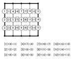
도 1은 GRID1에 의한 도트 패턴의 원리도(1)이다.1 is a principle diagram (1) of a dot pattern by GRID1.
도 2는 도트 패턴의 정보 도트 및 여기에 정의된 데이터의 비트 표시의 예를 나타내는 그림이다.2 is a diagram showing an example of information dots of a dot pattern and bit display of data defined herein.
도 3은 GRID1에 의한 키 도트를 설명하기 위한 그림이며, 정보 도트의 배치예를 나타내는 그림이다.3 is a figure for explaining the key dot by GRID1, and is a figure which shows the example of arrangement | positioning of an information dot.
도 4는 GRID1에 의한 정보 도트의 배치예를 나타내는 그림으로서, 정보 도트 및 여기에 정의된 데이터의 비트 표시의 예를 나타내는 그림이다.Fig. 4 is a diagram showing an example of the arrangement of information dots by GRID1, which is an illustration of an example of bit display of information dots and data defined therein.
도 5는 GRID1에 의한 정보 도트 및 여기에 정의된 데이터의 비트 표시의 예를 나타내는 그림이다.Fig. 5 is a diagram showing an example of information dot display by GRID1 and bit display of data defined here.
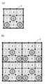
도 6은 GRID1에 의한 도트 패턴의 변형예를 나타내는 그림이다.6 is a diagram illustrating a modification of the dot pattern by GRID1.
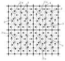
도 7은 GRID3에 의한 도트 패턴의 원리도이다.7 is a principle diagram of a dot pattern by GRID3.
도 8은 GRID3에 의한 정보 도트의 배치예를 나타내는 그림이다.8 is a diagram illustrating an arrangement example of information dots by GRID3.
도 9는 GRID3에 의한 키 도트와 정보 도트와의 배치 상태를 나타내는 설명도이다.9 is an explanatory diagram showing an arrangement state of key dots and information dots by GRID3.
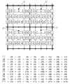
도 10은 GRID3에 의한 정보 도트 및 여기에 정의된 데이터의 비트 표시의 예를 나타내는 그림이다.Fig. 10 is a diagram showing an example of information dot display by GRID3 and bit display of data defined here.
도 11은 GRID3에 의한 정보 도트(3) 및 여기에 정의된 데이터의 비트 표시의 예를 나타내는 그림이다.Fig. 11 is a diagram showing an example of the bit display of the
도 12는 GRID3에 의한 도트 패턴의 변형예를 나타내는 그림이다.It is a figure which shows the modification of a dot pattern by GRID3.
도 13은 GRID4에 의한 도트 패턴의 원리도이다.It is a principle diagram of the dot pattern by GRID4.
도 14는 GRID4에 의한 정보 도트의 정의 방법을 나타낸 도(1)이다.14 is a diagram (1) showing a method of defining information dots by GRID4.
도 15는 GRID4에 의한 정보 도트의 정의 방법을 나타낸 도(2)이다.15 is a diagram (2) showing a method for defining information dots by GRID4.
도 16은 GRID4에 의한 정보 도트의 정의 방법을 나타낸 도(3)이다.Fig. 16 is a diagram (3) showing a method of defining information dots by GRID4.
도 17은 GRID4에 의한 정보 도트의 정의 방법을 나타낸 도(4)이다.Fig. 17 is a diagram (4) showing a method of defining information dots by GRID4.
도 18은 GRID4에 의한 광학 독취 수단에 있어서의 정보 도트의 독취순서를 설명하기 위한 그림이다.18 is a diagram for explaining the reading order of information dots in the optical reading means by GRID4.
도 19는 GRID4에 대하여, 기준 격자점 도트 대신에 키 도트를 배치한 그림이다.19 is a diagram in which key dots are disposed in place of the reference grid point dots for GRID4.
도 20은 GRID4에 대하여, 차분법을 이용한 정보 도트의 독취 방법에 대하여 설명하는 그림이다.20 is a diagram for explaining a reading method of information dots using the difference method for GRID4.
도 21은 GRID1에 디렉션 도트를 배치한 도(1)이다.Fig. 21 is a diagram (1) in which direction dots are arranged in GRID1.
도 22는 GRID1에 디렉션 도트를 배치한 도(2)의 정보 도트의 배치순서를 나 타내는 그림이다.Fig. 22 is a diagram showing the arrangement order of the information dots in Fig. 2 in which the direction dot is arranged in GRID1.
도 23은 GRID3에 디렉션 도트를 배치한 도(1)이다.Fig. 23 is a diagram in which direction dots are arranged in GRID3.
도 24는 GRID3에 디렉션 도트를 배치한 도(2)이다.FIG. 24 is a diagram in which direction dots are arranged in GRID3.
도 25는 GRID3의 정보 도트의 배치순서를 나타내는 도(1)이다.Fig. 25 is a diagram (1) showing an arrangement sequence of information dots of GRID3.
도 26은 GRID3의 디렉션 도트의 배치 위치를 나타내는 그림이다.It is a figure which shows the arrangement position of the direction dot of GRID3.
도 27은 GRID3의 정보 도트의 배치순서를 나타내는 도(2)이다.Fig. 27 is a diagram (2) showing an arrangement order of information dots of GRID3.
도 28은 GRID4에 디렉션 도트를 배치한 도(1)이다.Fig. 28 is a diagram (1) in which direction dots are arranged in GRID4.
도 29는 GRID4의 정보 도트의 배치순서를 나타내는 도(1)이다.Fig. 29 is a diagram (1) showing an arrangement sequence of information dots of GRID4.
도 30은 GRID4의 정보 도트의 배치순서를 나타내는 도(2)이다.30 is a diagram (2) showing an arrangement order of information dots of the GRID4.
도 31은 GRID4의 디렉션 도트의 배치 위치를 나타내는 그림이다.It is a figure which shows the arrangement position of the direction dot of GRID4.
도 32는GRID4의 정보 도트의 배치순서를 나타내는 도(3)이다.32 is a diagram (3) showing an arrangement sequence of information dots of GRID4.
도 33은 GRID4의 정보 도트의 배치순서를 나타내는 도(4)이다.Fig. 33 is a diagram (4) showing an arrangement sequence of information dots of GRID4.
도 34는 GRID1에 대하여, 정보 도트의 배치의 방법을 변경하여 블록의 방향을 정의하는 설명도(1)이다.34 is an explanatory diagram (1) in which GRID1 is changed in a method of arranging information dots to define a block direction.
도 35는 GRID1에 대하여, 정보 도트의 배치의 방법을 변경하여 블록의 방향을 정의하는 설명도(2)이다.FIG. 35 is an explanatory diagram (2) for defining the direction of a block by changing a method of arranging information dots for GRID1.
도 36은 GRID1에 대하여, 정보 도트의 배치의 방법을 변경하여 블록의 방향을 정의하는 설명도(3)이다.FIG. 36 is an explanatory diagram (3) for defining the direction of a block by changing a method of arranging information dots for GRID1.
도 37은 GRID1에 대하여, 정보 도트의 배치의 방법을 변경하여 블록의 방향을 정의하는 설명도(4)이다.FIG. 37 is an explanatory diagram (4) for defining the direction of a block by changing the method of arranging information dots for GRID1.
도 38은 블록이나 방향을 정의할 수 없는 경우의 배치예를 나타내는 도(1)이다.38 is a diagram (1) showing an example of arrangement in the case where a block or direction cannot be defined.
도 39는 블록이나 방향을 정의할 수 없는 경우의 배치예를 나타내는 도(2)이다.Fig. 39 is a diagram (2) showing an example of arrangement in the case where a block or direction cannot be defined.
도 40은 GRID3에 대하여, 정보 도트의 배치의 방법을 변경하여 블록의 방향을 정의하는 설명도(1)이다.40 is an explanatory diagram (1) in which GRID3 is changed in a method of arranging information dots to define a block direction.
도 41은 GRID3에 대하여, 정보 도트의 배치의 방법을 변경하여 블록의 방향을 정의하는 설명도(2)이다.FIG. 41 is an explanatory diagram (2) for defining GRID3 by changing a method of arranging information dots. FIG.
도 42는 GRID3에 대하여, 정보 도트의 배치의 방법을 변경하여 블록의 방향을 정의하는 설명도(3)이다.FIG. 42 is an explanatory diagram (3) for defining the direction of a block by changing the method of arranging information dots for GRID3.
도 43은 GRID3에 대하여, 정보의 배치순서를 설명하기 위한 도 정보 도트의 배치의 방법을 변경하여 블록의 방향을 정의하는 설명도(4)이다.FIG. 43 is an explanatory diagram (4) for defining the direction of a block by changing a method of arranging information dot for GRID3 for explaining the arrangement order of information.
도 44는 GRID4에 대하여, 정보 도트의 배치의 방법을 변경하여 블록의 방향을 정의하는 설명도(1)이다.FIG. 44 is an explanatory diagram (1) for defining the direction of a block by changing a method of arranging information dots for GRID4.
도 45는 GRID4에 대하여, 정보 도트의 배치의 방법을 변경하여 블록의 방향을 정의하는 설명도(2)이다.45 is an explanatory diagram (2) for GRID4, in which the direction of the block is defined by changing the arrangement of the information dots.
도 46은 GRID4에 대하여, 정보 도트의 배치의 방법을 변경하여 블록의 방향을 정의하는 설명도(3)이다.FIG. 46 is an explanatory diagram (3) for GRID4, in which the direction of the block is defined by changing the arrangement of information dots.
도 47은 본 실시 형태에 대하여, 디렉션 도트와 정보 도트의 판정 알고리즘을 설명하기 위한 그림이다.47 is a diagram for explaining a determination algorithm of direction dots and information dots in this embodiment.
도 48은 블록의 형상이 격자모양 이외인 블록에 대하여, 기준점의 배치의 방법에 의하여 블록의 방향을 정의하는 설명도(1)이다.FIG. 48 is an explanatory diagram (1) in which the direction of a block is defined by a method of arranging reference points with respect to a block whose shape of the block is other than a lattice shape.
도 49는 블록의 형상이 격자모양 이외인 블록에 대하여, 기준점의 배치의 방법에 의하여 블록의 방향을 정의하는 설명도(2)이다.FIG. 49 is an explanatory diagram (2) for defining a block direction by a method of arranging reference points for blocks whose shape is different from the lattice shape.
도 50은 블록의 형상을 사각형 영역으로 하지 않고, 일부의 기준점과 기준 격자점을 일치시킨 경우에 대하여, 기준점의 배치의 방법에 의하여 블록의 방향을 정의하는 설명도(1)이다.Fig. 50 is an explanatory diagram (1) in which the direction of the block is defined by the method of arranging the reference points in the case where a part of the reference points and the reference grid points are coincident without making the shape of the block into a rectangular region.
도 51은 블록의 형상을 사각형 영역으로 하지 않고, 일부의 기준점과 기준 격자점을 일치시켰을 경우에 대하여, 기준점의 배치의 방법에 의하여 블록의 방향을 정의하는 설명도(2)이다.FIG. 51 is an explanatory diagram (2) in which the direction of a block is defined by a method of arranging the reference points in a case where a part of the reference point and the reference grid point are coincident without making the shape of the block into a rectangular region.
도 52는 블록의 네 모퉁이에 기준점을 배치한 블록에 대하여, 정보 도트의 배치의 방법을 변경하여 블록의 방향을 정의하는 설명도(1)이다.Fig. 52 is an explanatory diagram (1) in which the direction of the block is defined by changing the method of arranging the information dots with respect to a block in which reference points are arranged at four corners of the block.
도 53은 블록의 네 모퉁이에 기준점을 배치한 블록에 대하여, 정보 도트의 배치의 방법을 변경하여 블록의 방향을 정의하는 설명도(2)이다.FIG. 53 is an explanatory diagram (2) for defining a block direction by changing a method of arranging information dots for a block in which reference points are arranged at four corners of the block.
도 54는 블록의 네 모퉁이에 기준점을 배치한 블록에 대하여, 정보 도트의 배치의 방법을 변경하여 블록의 방향을 정의하는 설명도(3)이다.FIG. 54 is an explanatory diagram (3) for defining a block direction by changing a method of arranging information dots with respect to a block in which reference points are arranged at four corners of the block.
도 55는 블록의 네 모퉁이에 기준점을 배치한 블록에 대하여, 정보 도트의 배치의 방법을 변경하여 블록의 방향을 정의하는 설명도(4)이다.FIG. 55 is an explanatory diagram (4) for defining a block direction by changing a method of arranging information dots for a block in which reference points are arranged at four corners of the block.
도 56은 블록의 네 모퉁이에 기준점을 배치한 블록에 대하여, 기준점의 일부를 격자점과 일치시키는 것으로 블록의 방향을 정의하는 설명도이다.FIG. 56 is an explanatory diagram for defining a block direction by aligning a part of the reference point with the lattice point in the block in which the reference point is arranged at four corners of the block.
도 57은 블록의 형상이 격자모양 이외인 블록에 대하여, 기준점의 크기를 변경하여 블록의 방향을 정의하는 설명도이다.FIG. 57 is an explanatory diagram for defining a block direction by changing the size of a reference point for a block whose shape is other than a lattice shape.
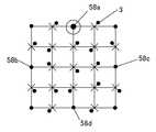
도 58은 블록의 형상이 격자모양의 블록에 대하여, 기준점의 크기를 변경하여 블록의 방향을 정의하는 설명도이다.Fig. 58 is an explanatory diagram for defining a block direction by changing the size of a reference point for a block of a lattice-shaped block;
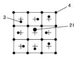
도 59는 블록의 중앙에 배치된 정보 도트의 크기를 다른 정보 도트보다 크게 하여 디렉션 도트로 했을 경우의 설명도이다.FIG. 59 is an explanatory diagram when the size of the information dot disposed in the center of the block is larger than other information dots to be a direction dot. FIG.
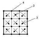
도 60은 정보 도트의 형상을 변경하여 블록의 방향을 정의하는 설명도이다.60 is an explanatory diagram in which the direction of a block is defined by changing the shape of the information dot.
도 61은 블록의 중앙에 배치된 정보 도트의 형상을 다른 정보 도트와 다르게 함으로써 블록의 방향을 정의하는 설명도이다.Fig. 61 is an explanatory diagram for defining the direction of a block by changing the shape of the information dot arranged in the center of the block from other information dots.
도 62는 블록의 중앙상의 격자 영역의 가상 격자점 상에 정보 도트를 배치하지 않음으로써 블록의 방향을 정의하는 설명도이다.62 is an explanatory diagram for defining the direction of a block by not placing information dots on a virtual lattice point of a lattice area on the center of the block.
도 63은 블록의 중앙상의 격자 영역의 가상 격자점 상에 정보 도트를 배치하는 것에 의하여 블록의 방향을 정의하는 설명도이다.63 is an explanatory diagram for defining the direction of a block by arranging information dots on a virtual lattice point of a lattice area on the center of the block.
<부호의 설명><Description of the code>
1 : 도트 패턴2 : 키 도트1: dot pattern 2: key dot
3 : 정보 도트4 : 기준 격자점 도트3: information dot 4: reference grid point dot
7a~7d : 기준 격자선8a, 8b : 격자선7a ~ 7d:
13 : 가상 격자점21 : 디렉션 도트13: virtual grid point 21: direction dot
28a, 28b : 횡방향 격자선34a, 34b, 34c : 격자 영역28a, 28b:
36a, 36b, 36c, 36d : 격자 영역36a, 36b, 36c, 36d: grid area
387~389, 391~393, 394~396 : 격자 영역387 ~ 389, 391 ~ 393, 394 ~ 396: Grid Area
401~403, 404~406 : 격자 영역401 ~ 403, 404 ~ 406: Grid Area
411 : 격자 영역441 : 격자 영역411
다음에, 본 발명을 도면을 토대로 하여 설명한다.Next, the present invention will be described based on the drawings.
먼저 본 발명에서 사용하는 도트 패턴의 기본 원리를 설명하고, 그 후, 이들 도트 패턴의 디렉션 도트의 구체적인 예에 대하여 설명한다.First, the basic principle of the dot pattern used by this invention is demonstrated, and the specific example of the direction dot of these dot patterns is then demonstrated.
(도트 패턴의 설명:GRID1)(Explanation of dot pattern: GRID1)
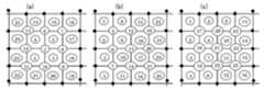
도 1~도 20은, 본 발명의 전제가 되는 도트 패턴의 원리를 설명하기 위한 그림이다. 이들 도 1~도 20에서는, GRID1에 의한 도트 패턴을 설명하기 위한 것으로서, 키 도트(2)가 포함되어 있다.1-20 is a figure for demonstrating the principle of the dot pattern used as a premise of this invention. 1-20, the
이 키 도트(2)는 본 발명의 디렉션 도트와는 달리, 본 발명의 특징적인 것은 아니다. 도 1~도 20에 기재된 키 도트(2)와 본 발명에 의한 디렉션 도트와의 차이는 도 21 이하에서 상세히 설명한다.This
도 1은 본 발명의 도트 패턴의 한 예인 GRID1을 나타내는 설명도이다. 도 2는 도트 패턴의 정보 도트 및 여기에 정의된 데이터의 비트 표시의 한 예를 나타내는 확대그림이다. 도 3(a), (b)는 키 도트(이 키 도트는 본 발명의 디렉션 도트와는 다르다)를 중심으로 배치한 정보 도트를 나타내는 설명도이다.BRIEF DESCRIPTION OF THE DRAWINGS It is explanatory drawing which shows GRID1 which is an example of the dot pattern of this invention. 2 is an enlarged view showing an example of information dots of a dot pattern and bit display of data defined therein. 3 (a) and 3 (b) are explanatory diagrams showing information dots arranged around a key dot (this key dot is different from the direction dot of the present invention).
본 발명의 도트 패턴을 사용한 정보 입출력 방법은, 도트 패턴(1)의 생성과 도트 패턴(1)의 인식과, 도트 패턴(1)으로부터 정보 및 프로그램을 출력하는 수단 으로 구성된다. 즉, 도트 패턴(1)을 카메라에 의하여 화상 데이터로서 수납하고, 먼저, 기준 격자점 도트(4)를 추출하고, 다음에 본래 기준 격자점 도트(4)가 있는 위치에 도트가 찍혀 있지 않는 것으로부터 키 도트(2)[여기에서의 키 도트(2)는 본 발명의 디렉션 도트와는 다르다]를 추출하고, 다음에 정보 도트(3)를 추출함으로써 디지털화하여 정보 영역을 추출하여 정보의 수치화를 꾀하고, 그 수치 정보에 의해, 이 도트 패턴(1)으로부터 정보 및 프로그램을 출력시킨다. 예를 들면, 이 도트 패턴(1)으로부터 음성 등의 정보나 프로그램을 정보 출력장치, PC, PDA 또는 휴대전화 등에 출력시킨다.The information input / output method using the dot pattern of this invention consists of generation | occurrence | production of the
본 발명의 도트 패턴(1)의 생성은, 도트 코드 생성 알고리즘에 의하여, 음성 등의 정보를 인식시키기 위하여 미세한 도트, 즉, 키 도트, 정보 도트, 기준 격자점 도트(4)를 소정 규칙에 준하여 배열한다. 도 1에 나타낸 바와 같이, 정보를 나타내는 도트 패턴(1)의 블록은, 키 도트(2)를 중심으로 5×5의 기준 격자점 도트(4)를 배치하고, 4점의 기준 격자점 도트(4)에 둘러싸인 중심의 가상 격자점(5)의 주위에 정보 도트(3)를 배치한다. 이 블록에는 임의의 수치 정보가 정의된다. 도 1의 도시예에서는, 도트 패턴(1)의 블록(굵은 선 테두리 내)을 4개 병렬시킨 상태를 나타내고 있다. 다만, 도트 패턴(1)은 4 블록으로 한정되지 않는 것은 물론이다.In the generation of the
1개의 블록에 1개로 대응한 정보 및 프로그램을 출력시키거나, 또는, 복수의 블록에 1개로 대응한 정보 및 프로그램을 출력시킬 수가 있다.One information and program corresponding to one block can be outputted, or one information and program corresponding to one block can be outputted to a plurality of blocks.
기준 격자점 도트(4)는, 카메라로 이 도트 패턴(1)을 화상 데이터로서 수납 할 때에, 이 카메라의 렌즈가 왜곡되거나 사선 촬상, 지면의 신축, 매체 표면의 만곡, 인쇄 시의 왜곡을 교정할 수 있다. 구체적으로는 왜곡된 4점의 기준 격자점 도트(4)를 원래의 정방형으로 변환하는 보정용 함수(Xn, Yn)=f(Xn', Yn')를 구하고 이와 동일한 함수로 정보 도트(3)를 보정하여, 올바른 정보 도트(3)의 벡터를 구한다.When the
도트 패턴(1)에 기준 격자점 도트(4)가 배치되어 있으면, 이 도트 패턴(1)을 카메라로 수납한 화상 데이터는, 카메라가 원인인 왜곡을 보정함으로써, 왜곡율이 높은 렌즈를 부착한 보급형 카메라로 도트 패턴(1)의 화상 데이터를 수납할 때에도 정확하게 인식할 수 있다. 또한, 도트 패턴(1)의 면에 대하여 카메라를 비스듬히 하여 읽어 들이더라도, 그 도트 패턴(1)을 정확하게 인식할 수 있다.If the reference
키 도트(2)는, 도 1에 나타낸 바와 같이, 사각형 모양으로 배치된 기준 격자점 도트(4)의 실질적으로 중심 위치에 있는 1개의 기준 격자점 도트(4)를 일정 방향으로 어긋나게 배치한 도트이다. 이 키 도트(2)는, 정보 도트(3)를 나타내는 1 블록 분의 도트 패턴(1)의 대표점이다. 예를 들면, 도트 패턴(1)의 블록 중심의 기준 격자점 도트(4)를 상방으로 0.2㎜ 옮긴 것이다. 정보 도트(3)가 X, Y 좌표치를 나타내는 경우에, 키 도트(2)를 하방으로 0.2㎜ 옮긴 위치가 좌표점이 된다. 다만, 이 수치는 이에 한정되지 않고, 도트 패턴(1) 블록의 대소에 응하여 변할 수 있다.As shown in Fig. 1, the
정보 도트(3)는 여러 가지의 정보를 인식시키는 도트이다. 이 정보 도트(3)는, 키 도트(2)를 대표점으로 하여, 이 주변에 배치함과 동시에, 4점의 기준 격자 점 도트(4)로 둘러싸인 중심을 가상 격자점(5)으로 하고, 이를 시점으로 하여 벡터에 의하여 표현한 종점에 배치한 것이다. 예를 들면, 이 정보 도트(3)는, 기준 격자점 도트(4)로 둘러싸이고, 도 2에 나타낸 바와 같이, 이 격자점(5)에서 0.2㎜ 떨어진 도트는, 벡터로 표현되는 방향과 길이를 가지기 때문에, 시계 방향으로 45도씩 회전시켜 8 방향으로 배치하여, 3비트를 표현한다. 따라서, 1 블록의 도트 패턴(1)으로 3비트×16개=48비트를 표현할 수 있다.The information dot 3 is a dot which recognizes various kinds of information. The information dot 3 has the
도시하는 예에서는 8 방향으로 배치하여 3 비트를 표현하고 있으나, 이에 한정되지 않고, 16 방향으로 배치하여 4 비트를 표현할 수도 있으며, 여러 가지 변경할 수 있는 것은 물론이다.In the illustrated example, three bits are represented by being arranged in eight directions. However, the present invention is not limited thereto, and four bits may be represented by being arranged in sixteen directions, and various modifications may be made.
키 도트(2), 정보 도트(3) 또는 기준 격자점 도트(4)의 직경은, 외관과 지질에 대한 인쇄의 정도, 카메라의 해상도 및 최적의 디지털화를 고려하여, 0.1㎜ 정도가 바람직하다.The diameter of the
또한, 촬상 면적에 대한 필요한 정보량과, 각종 도트(2), (3), (4)의 오인을 고려하여 기준 격자점 도트(4)의 간격은 가로세로 1㎜ 전후가 바람직하다. 기준 격자점 도트(4) 및 정보 도트(3)와의 오인을 고려하여, 키 도트(2)의 어긋남은 격자 간격의 20% 전후가 바람직하다.In addition, in consideration of the necessary amount of information on the imaging area and the misunderstanding of the
이 정보 도트(3)와 4점의 기준 격자점 도트(4)로 둘러싸인 가상 격자점과의 간격은, 인접하는 가상 격자점(5) 간의 거리의 15~30% 정도의 간격이 바람직하다. 정보 도트(3)와 가상 격자점(5) 간의 거리가 이 간격보다 가까우면, 도트끼리는 큰 덩어리로 시인(視認)되기 쉽고, 도트 패턴(1)으로서 보기 어렵게 되기 때문이다. 반대로, 정보 도트(3)와 가상 격자점(5)과의 거리가 이 간격보다 멀면, 인접하는 어떤 가상 격자점(5)을 중심으로 하여 벡터 방향성을 갖도록 한 정보 도트(3)인지의 인정이 곤란하게 되기 때문에 있다.As for the space | interval between this information dot 3 and the virtual grid point surrounded by four reference
예를 들면, 정보 도트(3)는, 도 3(a)에 나타낸 바와 같이, 키 도트(2)를 중심으로 시계방향으로 I1로부터 I16을 배치하는 격자 간격은 1㎜로서, 4㎜×4㎜로 3비트×16=48비트를 표현한다.For example, the
블록 내에 개개로 독립한 정보 내용을 가지며 또한 다른 정보 내용에 영향을 받지 않는 서브 블록을 다시 설치할 수 있다. 도 3(b)는 이를 도시한 것으로서, 4개의 정보 도트(3)로 구성되는 서브 블록[I1, I2, I3, I4],[I5, I6, I7, I8],[I9, I10, I11, I12],[I13, I14, I15, I16]은 각각 독립한 데이터(3 비트×4=12 비트)가 정보 도트(3)로 전개되도록 되어 있다. 이와 같이 서브 블록을 설치함으로써, 에러 체크를 서브 블록 단위로 용이하게 할 수 있다.It is possible to re-install sub-blocks each having independent information content in the block and not affected by other information content. FIG. 3 (b) shows this and shows a sub-block [I1 , I2 , I3 , I4 ], [I5 , I6 , I7 , I8 ] composed of four
정보 도트(3)의 벡터 방향(회전 방향)은, 30도~90도마다 균등하게 정하는 것이 바람직하다.It is preferable to determine the vector direction (rotation direction) of the information dot 3 uniformly every 30 degrees-90 degrees.
도 4는 정보 도트(3) 및 여기에 정의된 데이터의 비트 표시의 예이며, 다른 형태를 나타내는 것이다.4 is an example of the bit display of the
또한, 정보 도트(3)에 있어서 기준 격자점 도트(4)로 둘러싸인 가상 격자점(5)으로부터 장단(長短)의 2종류를 사용하고, 벡터 방향을 8 방향으로 하면, 4 비트를 표현할 수 있다. 이 때, 긴 쪽은 인접하는 가상 격자점(5) 간의 거리의 25~30% 정도, 짧은 쪽은 15~20% 정도가 바람직하다. 다만, 장단의 정보 도트(3)의 중심 간격은, 이들의 도트 직경보다 길어지는 것이 바람직하다.In the
4점의 기준 격자점 도트(4)로 둘러싸인 정보 도트(3)는, 외관을 고려하여, 1 도트가 바람직하다. 그러나, 외관을 무시하고, 정보량을 많이 하고 싶은 경우에는, 1 벡터마다, 1 비트를 할당 정보 도트(3)를 복수 도트로 표현함으로써, 다량의 정보를 가질 수가 있다. 예를 들면, 동심원(8) 방향의 벡터에서는, 4점의 격자 도트(4)로 둘러싸인 정보 도트(3)로 28의 정보를 표현할 수 있고, 1 블록의 정보 도트 16개로 2128이 된다.As for the information dot 3 surrounded by four reference
도 5는 정보 도트 및 여기에 정의된 데이터의 비트 표시 예이며, (a)는 도트를 2개, (b)는 도트를 4개, (c)는 도트를 5개 배치한 것을 나타낸다.5 is an example of displaying bits of information dots and data defined therein, (a) shows two dots, (b) shows four dots, and (c) shows five dots.
도 6은 도트 패턴의 변형예를 나타내는 것으로서, (a)는 정보 도트 6개 배치형, (b)는 정보 도트 9개 배치형, (c)는 정보 도트 12개 배치형, (d)는 정보 도트 36개 배치형의 개략도이다.Fig. 6 shows a modification of the dot pattern, in which (a) is arranged 6 information dots, (b) is arranged 9 information dots, (c) is arranged 12 information dots, and (d) is information. A schematic diagram of the arrangement of 36 dots.
도 1과 도 3에 나타내는 도트 패턴(1)은, 1 블록에 16(4×4)의 정보 도트(3)를 배치한 예를 나타내고 있다. 그러나, 이 정보 도트(3)는 1 블록에 16개 배치하는 것에 국한되지 않고 , 여러 가지로 변경할 수 있다. 예를 들면, 필요로 하는 정보량의 대소 또는 카메라의 해상도에 대응하여, 정보 도트(3)를 1 블록에 6개(2×3) 배치한 것(a), 정보 도트(3)를 1 블록에 9개(3×3) 배치한 것(b), 정보 도트(3)를 1 블록에 12개(3×4) 배치한 것(c), 또는 정보 도트(3)를 1 블록에 36개 배치한 것(d)이 있다.The
(도트 패턴의 설명:GRID3)(Explanation of dot pattern: GRID3)
다음에 GRID3에 대하여 설명한다.Next, GRID3 will be described.
도 7은 본 발명의 도트 패턴의 한 예를 나타내는 설명도, 도 8은 도트 패턴의 정보 도트 및 여기에 정의된 데이터 비트 표시의 한 예를 나타내는 확대도, 도 9(a), (b), (c)는 키 도트와 정보 도트와의 배치 상태를 나타내는 설명도이다.Fig. 7 is an explanatory diagram showing an example of a dot pattern of the present invention, Fig. 8 is an enlarged view showing an example of information dots of a dot pattern and data bit display defined therein, Figs. 9 (a), (b), (c) is explanatory drawing which shows the arrangement state of a key dot and an information dot.
본 발명의 도트 패턴을 사용한 정보 입출력 방법은, 도트 패턴(1)의 인식과 이 도트 패턴(1)으로부터 정보 및 프로그램을 출력하는 수단으로 구성된다.The information input / output method using the dot pattern of this invention is comprised by the recognition of the
즉, 도트 패턴(1)을 카메라에 의하여 화상 데이터로서 수납하고, 먼저, 기준 격자점 도트(4)를 추출하고, 이를 가상 기준 격자점(6)의 위치라고 판정하고, 이들 가상 기준 격자점(6)을 연결하는 직선을 기준 격자선(7)으로 한다. 그리고, 이 기준 격자선(7) 상에서, 본래 기준 격자점 도트(4)가 있어야 할 가상 기준 격자점(6)의 위치에 도트가 배치되어 있지 않은 경우, 이 가상 기준 격자점(6)의 주변의 도트를 추출하고, 이를 키 도트(2)(블록의 네 귀퉁이 모서리부)로 한다. 그리고, 다음에 상기 가상 기준 격자점(6)끼리를 연결하는 종횡의 격자선(8a), (8b)를 설정하여, 이 격자선 끼리의 교점을 가상 격자점(11)(제1 가상 격자점)으로 한다. 그리고 이 가상 격자점(11)의 주위의 도트를 탐색하고, 이 가상 격자점(11)으로부터의 거리와 방향으로 정의되는 정보 도트(3)를 추출한다.That is, the
또한, 가상 기준 격자점(6)끼리를 사선 방향끼리 연결하는 사선 격자선(8c)을 상정하고, 이 사선 격자선(8c)끼리의 교점도 가상 격자점(12)(제2 가상 격자점) 으로 한다. 그리고 이 가상 격자점(12)의 주위의 도트도 탐색하여, 그 가상 격자점(12)로부터의 거리와 방향으로 정의되는 정보 도트(3)를 추출한다.In addition, a
다음에, 키 도트(2)의 가상 기준 격자점(6) 또는 가상 격자점(11)으로부터의 방향에 따라 상기 블록의 방향이 결정된다. 예를 들면, 키 도트(2)가 가상 격자점으로부터 +y 방향으로 어긋나 있는 경우에는 종방향을 정위(正位)로 하여 블록 내의 정보 도트(3)를 인식하면 된다.Next, the direction of the block is determined according to the direction from the virtual
또한, 키 도트(2)가 가상 기준 격자점(6) 또는 가상 격자점(11)으로부터 -y 방향으로 어긋나 있으면 상기 블록을 블록 중심을 축으로 180도 회전시킨 방향을 정위로 하여 블록 내의 정보 도트(3)를 인식하면 된다.If the
또한, 키 도트(2)가 가상 기준 격자점(6) 또는 가상 격자점(11)으로부터 -x 방향으로 어긋나 있으면 상기 블록을 블록 중심을 축으로 시계 방향으로 90도 회전시킨 방향을 정위로 하여 블록 내의 정보 도트(3)를 인식하면 된다.If the
또한, 키 도트(2)가 가상 기준 격자점(6) 또는 가상 격자점(11)으로부터 +x 방향으로 어긋나 있으면 상기 블록을 블록 중심을 축으로 반시계방향으로 90도 회전시킨 방향을 정위로 하여 블록 내의 정보 도트(3)를 인식하면 된다.If the
광학 독취 수단으로 읽어낸 도트 패턴(1)의 화상이 프래임 버퍼에 축적되면, 상기 광학 독취 수단의 중앙 처리장치(CPU)는, 프래임 버퍼의 도트를 해석하여, 각 정보 도트(3)의 가상 격자점(11), (12)으로부터의 거리와 방향에 따라 정보 도트(3)마다 정의된 수치를 복호한다. 그리고 이들 수치는 xy 좌표 또는 코드로서 광학 독취 수단 또는 PC의 메모리에 격납된 정보와 대조되어, 상기 xy 좌표 또는 코 드에 대응하는 음성, 화상, 동영상, 문자, 프로그램 등을 읽어내, 표시 수단, 음성 및 화상 출력 수단으로 출력된다.When the image of the
본 발명의 도트 패턴(1)의 생성은, 도트 코드 생성 알고리즘에 의하여, 음성 등의 정보를 인식시키기 때문에 미세한 도트, 즉, 키 도트(2), 정보 도트(3), 기준 격자점 도트(4)를 소정의 규칙에 준하여 배열한다.The
도 7에 나타낸 바와 같이, 인쇄물 등의 매체면의, 정사각형 또는 직사각형인 사각형 영역을 블록으로 한다. 그리고, 상기 블록의 테두리를 구성하는 종방향 및 횡방향의 직선을 기준 격자선(7)(도 1에서 굵은 테두리로 나타낸 선)으로 하고, 상기 기준 격자선(7) 상의 소정 간격 마다 가상 기준 격자점(6)을 설치하고, 가상 기준 격자점(6) 상에 기준 격자점 도트(4)를 배치한다. 다음에, 상기 가상 기준 격자점(6)끼리를 연결하고 또한 상기 기준 격자선(7)과 평행한 직선을 격자선(8a), (8b)으로 하고, 격자선(8a), (8b)끼리의 교점을 가상 격자점(11)(제1 가상 격자점)으로 한다.As shown in Fig. 7, a rectangular or rectangular area of a medium surface such as a printed matter is used as a block. The vertical and horizontal straight lines constituting the edge of the block are referred to as the reference grid lines 7 (lines indicated by bold borders in FIG. 1), and virtual reference grids are provided at predetermined intervals on the reference grid lines 7. The
또한, 상기 가상 기준 격자점(6)끼리를 사선 방향으로 연결하는 사선 격자선(8c)을 설정하고, 이 사선 격자선(8c)끼리의 교점도 가상 격자점(12)(제2 가상 격자점)으로 한다.Moreover, the
이와 같이 설정된 가상 격자점(11), (12)을 기준으로 거리와 방향을 가지는 한 개 또는 복수의 정보 도트(3)를 각각 배치하여 도트 패턴을 생성한다.A dot pattern is generated by arranging one or a plurality of
카메라로 이 도트 패턴(1)을 화상 데이터로서 수납할 때에, 그 카메라의 렌즈의 왜곡이나 사선 촬상, 지면의 신축, 매체 표면의 만곡, 인쇄 시의 왜곡을 상기 기준 격자점 도트(4)에 의하여 교정할 수 있다. 구체적으로는 왜곡된 4점의 가상 격자점을 원래의 정사각형으로 변환하는 보정용 함수(Xn, Yn)=f(Xn', Yn')를 구하고, 이와 동일한 함수로 정보 도트를 보정하여, 올바른 정보 도트(3)의 벡터를 구한다.When storing the
도트 패턴(1)에 기준 격자점 도트(4)를 배치하고 있으면, 이 도트 패턴(1)을 카메라로 수납한 화상 데이터는, 카메라가 원인인 왜곡을 보정함으로써, 왜곡율이 높은 렌즈를 부착한 보급형 카메라로 도트 패턴(1)의 화상 데이터를 수납할 때에도 정확하게 인식할 수 있다. 또한, 도트 패턴(1)의 면에 대하여 카메라를 비스듬히 하여 읽어내더라도, 그 도트 패턴(1)을 정확하게 인식할 수 있다.If the reference
키 도트(2)는, 도 7에 나타낸 바와 같이, 사각형상(矩形狀)으로 배치한 가상 격자점의 대략 중심 위치에 있는 1개의 가상 격자점(11)을 기준으로 거리와 방향에 따라 배치된 도트이다. 이 키 도트(2)는, 한 묶음의 정보 도트군(群)을 나타내는 1 블록 분의 도트 패턴(1)의 대표점이다. 예를 들면, 도트 패턴(1)의 블록의 중심의 가상 격자점(11)으로부터 상방으로 0.2㎜ 어긋난 위치에 배치되어 있는 경우이다. 따라서, 정보 도트(3)가 가상 격자점으로부터의 X, Y 좌표치로 정의되는 경우에는, 키 도트(2)로부터 하부로 0.2㎜의 거리의 위치가 가상 격자점(좌표점)이 된다. 다만, 이 수치(0.2㎜)는 여기에 국한되지 않고 , 도트 패턴(1)의 블록 대소에 응하여 변할 수 있다.As shown in FIG. 7, the
정보 도트(3)는 여러 가지의 정보를 인식시키는 도트이다. 이 정보 도트(3) 는, 도 12의 경우, 키 도트(2)를 대표점으로 하여, 그 주변에 배치함과 동시에, 4점의 가상 격자점(11)(제1 가상 격자점)으로 둘러싸인 중심을 가상 격자점(12)(제2 가상 격자점)으로 하고, 이를 시점으로 하여 벡터에 의하여 표현한 종점에 배치한 것이다. 예를 들면, 이 정보 도트(3)는, 가상 격자점(11), (12)으로 둘러싸이고, 도 8에 나타낸 바와 같이, 이 가상 격자점(11), (12)으로부터 0.2㎜ 떨어진 도트는, 벡터로 표현되는 방향과 길이를 가지기 때문에, 시계 방향으로 45도씩 회전시켜 8 방향으로 배치하여, 3 비트를 표현하고 있다.The information dot 3 is a dot which recognizes various kinds of information. In the case of FIG. 12, the information dot 3 has the
이 그림에 따르면, 1 블록의 도트 패턴(1)으로 3 비트×16개=48 비트를 표현할 수 있다.According to this figure, 3 bits x 16 = 48 bits can be represented by the
한편, 도시하는 예에서는 8 방향으로 배치하여 3 비트를 표현하고 있으나, 이에 국한하지 않고, 16 방향으로 배치하여 4 비트를 표현하는 것도 가능하여, 여러 가지 변경할 수 있는 것은 물론이다.On the other hand, in the illustrated example, three bits are expressed in eight directions. However, the present invention is not limited thereto, and four bits can be expressed in sixteen directions, and various modifications can be made.
또한, 도 7에서는 모든 가상 격자점에 대하여, 이 가상 격자점을 시점으로 하여 그 종점 위치에 정보 도트를 배치했으나, 이에 국한되지 않고, 가상 격자점 상에 도트가 배치되어 있는지 없는지로 정보를 정의하도록 해도 된다. 예를 들면 가상 격자점 상에 도트가 배치되고 있으면 ‘1’, 배치되어 있지 않으면 ‘0’이라는 정보를 정의할 수 있다.In FIG. 7, information dots were arranged at the end positions of the virtual lattice points with respect to all the virtual lattice points. However, the information is defined by whether or not the dots are arranged on the virtual lattice points. You may do so. For example, if a dot is disposed on a virtual lattice point, '1' may be defined, and if not, '0' may be defined.
키 도트(2), 정보 도트(3) 또는 기준 격자점 도트(4)의 직경은, 외관과 지질에 대한 인쇄의 정도, 카메라의 해상도 및 최적의 디지털화를 고려하여, 0.1㎜정도가 바람직하다.The diameter of the
또한, 촬상 면적에 대한 필요한 정보량과 각종 도트(2), (3), (4)의 오인을 고려하여 기준 격자점 도트(4)의 간격은 가로세로 1 ㎜전후가 바람직하다. 기준 격자점 도트(4) 및 정보 도트(3)와의 오인을 고려하여, 키 도트(2)의 어긋남은 격자 간격의 20% 전후가 바람직하다.In addition, in consideration of the necessary amount of information on the imaging area and the misunderstanding of
이 정보 도트(3)와 가상 격자점(11) 또는 (12)와의 간격은, 인접하는 가상 격자점(11), (12) 간의 거리의 15~30% 정도의 간격인 것이 바람직하다. 정보 도트(3)와 가상 격자점(11), (12) 간의 거리가 이 간격보다 가까우면 도트끼리가 큰 덩어리로 시인되기 쉬어, 도트 패턴(1)으로서 보기 어렵기 때문이다. 반대로, 정보 도트(3)와 가상 격자점 간의 거리가 이 간격보다 멀면, 인접하는 어느 하나의 가상 격자점(11), (12)을 중심으로 하여 벡터 방향성을 갖도록 한 정보 도트(3)인가의 인정이 곤란하게 되기 때문이다.The interval between the
도 9는, 블록 내에 있어서의 정보 도트(3)의 독취 순서를 나타낸 것으로서, 동도 중의 동그라미가 붙은 숫자는, 각각 가상 격자점(11), (12) 마다 배치된 정보 도트(3)의 배치 영역을 의미하고 있는 것으로 한다.Fig. 9 shows the reading order of the
예를 들면, 도 9(a)의 경우, 블록 중심의 (1)(도중에서 동그라미로 둘러싸인 숫자 ‘1’을 의미하고 있다. 이하 같다)를 중심으로 하여, 그곳에서부터 시계방향으로 (1)부터(25)가 배치되어 있다. 이 때의 격자 간격은 예를 들면 1 ㎜이고, 4 ㎜×4 ㎜로 3 비트×1625=4875 비트를 표현한다.For example, in the case of Fig. 9A, the center of the block is (1) (which means the number '1' surrounded by circles in the figure. 25 is arrange | positioned. The lattice spacing at this time is, for example, 1 mm, representing 3 bits x 1625 = 4875 bits at 4 mm x 4 mm.
도 9(b)는, 블록의 좌상의 사각형 영역의 정보 도트(1)로부터 종방향으로 순차적으로 (4)까지 배치한 후, 종횡 방향의 격자선 끼리의 교점에 배치된 정보 도 트(5)~(7)를 배치하고 있다.Fig. 9 (b) shows the
도 9(c)는, 블록 좌상의 사각형 영역의 정보 도트(1)로부터 종방향으로 (16)까지 순차적으로 배치한 후, 종횡의 격자선 끼리의 교점에 배치된 정보 도트(17)~(25)를 배치하고 있다.9 (c) is sequentially arranged from the information dot 1 in the rectangular region on the upper left of the block to the
도 10은 정보 도트 및 여기에 정의된 데이터의 비트 표시의 예로서, 다른 형태를 나타낸다.Fig. 10 shows another form as an example of bit display of information dots and data defined herein.
또한, 정보 도트(3)에 대하여 기준 격자점 도트(4)로 둘러싸인 가상 격자점(11), (12)로부터 단(도 10의 상단), 장(도 10의 하단)의 2 종류를 사용하여, 벡터 방향을 8 방향으로 하면, 4 비트를 표현할 수 있다. 이때, 긴 쪽은 인접하는 가상 격자점 간의 거리의 25~30% 정도, 짧은 쪽은 15~20% 정도가 바람직하다. 다만, 장, 단의 정보 도트(3)의 중심 간격은, 이들의 도트 직경보다 길어지는 것이 바람직하다.In addition, two types of virtual grid points 11 and 12 enclosed by the reference
4점의 가상 격자점(11), (12)으로 둘러싸인 정보 도트(3)는, 외관을 고려하여, 1 도트가 바람직하다. 그러나, 외관을 무시하고, 정보량을 많이 하고 싶은 경우는, 1 벡터마다 1 비트를 할당하여 정보 도트(3)를 복수의 도트로 표현함으로써, 다량의 정보를 가질 수가 있다. 예를 들면, 동심원(8) 방향의 벡터에서는, 4점의 기준 격자점 도트(4)로 둘러싸인 정보 도트(3)로 28의 정보를 표현할 수 있어, 1 블록의 정보 도트 16개로 2128이 된다.As for the information dot 3 surrounded by four virtual grid points 11 and 12, one dot is preferable in consideration of an external appearance. However, when disregarding the appearance and wanting to increase the amount of information, a large amount of information can be obtained by allocating one bit for each vector and expressing the information dot 3 in a plurality of dots. For example, in a vector in the
도 11은 정보 도트(3) 및 여기에 정의된 데이터의 비트 표시의 예로서, (a) 는 도트를 2개, (b)는 도트를 4개 및 (c)~(e)는 도트를 5개, (f)는 7개 배치한 것을 나타낸다.Fig. 11 shows an example of the information display of the
도 12는 도트 패턴의 변형예를 나타내는 것으로서, (a)는 블록 내에 정보 도트(3)를 8개 배치한 것, (b)는 정보 도트(3)를 13개 배치한 것, (c)는 정보 도트(3)를 18개 배치한 것, (d)는 정보 도트(3)를 41개 배치한 것이다.12 shows a modification of the dot pattern, in which (a) shows eight
전술한 도 7과 도 9에 나타내는 도트 패턴(1)은, 1 블록에 25개의 정보 도트(3)를 배치한 예를 나타내고 있다. 그러나, 이 정보 도트(3)는 1 블록에 25개 배치하는데 국한하지 않고, 여러 가지로 변경할 수 있다. 예를 들면, 필요로 하는 정보량의 대소 또는 카메라의 해상도에 따라, 정보 도트(3)를 1 블록에 8개 배치한 것[도 12(a)], 정보 도트(3)를 1 블록에 13개 배치한 것[도 12(b)], 정보 도트(3)를 1 블록에 18개 배치한 것[도 12(c)], 또는 정보 도트(3)를 1 블록에 41개 배치한 것[도 12(d)]이 있다.The
(도트 패턴의 설명:GRID4)(Explanation of dot pattern: GRID4)
다음에 GRID4에 대하여 설명한다.Next, GRID4 will be described.
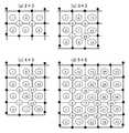
도 13은, 본 발명의 실시 형태인 도트 패턴을 구체적으로 나타낸 것으로서, (a)는 4×4 격자, (b)는 5×4 격자, (c)는 6×4 격자의 도트 패턴을 나타내고 있다.Fig. 13 specifically shows a dot pattern as an embodiment of the present invention, where (a) shows a 4 × 4 grid, (b) shows a 5 × 4 grid, and (c) shows a dot pattern of 6 × 4 grid. .
동도(a)에 있어서, 먼저 사각형을 구성하는 종횡 방향의 기준 격자선(7a)~(7d)을 설치하고, 이 사각형 내의 소정 간격 마다 가상 격자점(13)이 배치되어 있다.In the same figure (a), first,
기준 격자선(7a)~(7d) 및 가상 격자점(13)에 대하여는, 실제로 지면(매체면)에 인쇄되는 것이 아니고, 어디까지나 컴퓨터 화상 메모리 상에 도트 패턴을 배치할 때, 또는 도트 패턴을 읽어 들일 때에 가상적으로 설정된 것이다.The
다음에, 상하 횡방향의 기준 격자선(7a), (7b)상의 가상 기준 격자점(14) 상에 기준 격자점 도트(4)를 배치한다.Next, the reference
다음에, 가상 격자점(13)끼리를 연결하는 종횡 방향의 격자선(8a), (8b)를 상정하여, 이 격자선(8a), (8b)끼리의 교점을 마찬가지로 가상 격자점(13)으로 한다.Next, assuming the
다음에, 가상 격자점(13)을 기준으로 거리와 방향을 가지는 정보 도트(3)를 가상 격자점(13) 마다 1 또는 2 이상 배치하여 도트 패턴을 생성한다. 도 13에서는 가상 격자점(13) 마다 1개의 정보 도트(3)가 배치되어 있다.Next, one or two or
이상으로 설명한 도 13(a)는 격자수를 종방향으로 4개, 횡방향으로 4개 단위로 정보 도트(3)를 배치했을 경우(4×4 격자)이고, 동도(b)는 5×4 격자, (c)는 6×4 격자를 각각 나타내고 있다.13A described above is a case where the
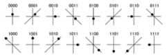
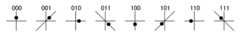
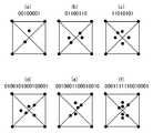
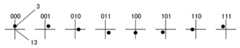
도 14는 정보 도트(3)의 정의를 나타낸 것으로서, 가상 격자점(13)을 중심으로 정보 도트(3)의 방향으로 값을 정의한 것이다. 동도에서는 가상 격자점을 통과하는 격자선을 기준으로 시계 방향으로 45도씩 8 방향으로 정보 도트를 배치함으로써, 합계 8 방법(2진법으로 000으로부터 111, 3 비트)의 정보를 정의할 수 있도록 되어 있다.FIG. 14 shows the definition of the
또한, 도 15는 상기 방향으로 다시 거리를 2 단계로 함으로써 합계 16방법(2 진법으로, 0000~1111, 4 비트)의 정보를 정의할 수 있도록 되어 있다.In addition, FIG. 15 makes it possible to define a total of 16 methods (0000 to 1111, 4 bits in binary) by setting the distance again in two steps in the above direction.
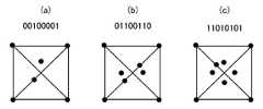
도 16은, 가상 격자점(13)을 중심으로 동심원 상에 복수의 정보 도트(3)를 배치하는 경우로서, 그 위치는 도트가 있는 경우를 1, 없는 경우를 0으로서 정의함으로써, 8 비트를 정의할 수 있으며, 즉 연직 방향에 위치하는 도트를 1비트 째로 하여 시계방향으로 비트 정보를 정의할 수 있다.FIG. 16 shows a case where a plurality of
도 17은 상기 동심원을 2개로 한 것으로서, 16 비트를 정의할 수 있다. 이와 같이 함으로써, 1개의 가상 격자점(13)에 대하여 방대한 정보량을 정의할 수 있다.17 shows two concentric circles, and 16 bits can be defined. In this way, a large amount of information can be defined for one
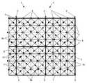
도 18은, 광학 독취 수단에 있어서 정보 도트(3)의 독취 순서를 설명하기 위한 것이다. 동도에 있어서 동그라미가 붙은 숫자는 편의적인 것으로서, 실제로는 도 13(a)~(c)에 나타난 도트 패턴으로 되어 있다.18 is for explaining the reading order of the information dot 3 in the optical reading means. The circled numerals in the figure are convenient, and are actually in the dot pattern shown in Figs. 13A to 13C.
동도(a)에서는, 먼저 좌측 종방향의 기준 격자선(7c)을 따라 종방향으로 가상 격자점마다의 정보 도트를 읽어낸 후[동그라미가 붙은 숫자(1)~(3)], 다음의 종방향 격자선(8b) 상의 가상 격자점(13)을 위로부터 순차적으로 읽어낸다[동그라미가 붙은 숫자(4)~(6)]. 이와 같이 하여 순차적으로 가상 격자점(13)마다 읽어 들여 실행한다.In the same figure (a), first, the information dot for every virtual grid point is read out longitudinally along the left longitudinal
한편, 이상의 설명에서는 격자마다의 독취 순서는 종방향의 격자선(8b)의 왼쪽으로부터 순서를 정했으나, 정보를 배치, 읽어내는 격자 순서는 임의로 설정하여도 되는 것은 물론이다.On the other hand, in the above description, the reading order for each lattice is determined from the left side of the
도 19는, 기준 격자선 상의 가상 격자점(13) 상에, 기준 격자점 도트(4) 대신에 키 도트(2)를 배치한 예이다. 기준 격자선(7a)의 중간 위치의 가상 격자 점(13)을 기준으로 상방향으로 옮긴 위치에 키 도트(2)를 배치하고 있다.19 shows an example in which the
이러한 키 도트(2)에 의하여, 도트 패턴의 방향을 정의할 수 있다.By such a
도 20은 차분법을 사용한 정보 도트(3)의 독취 방법에 대하여 설명한 것이다. 이하에서는 도면의 사각형 숫자를 [], 동그라미가 붙은 숫자를 ()로 표현한다.Fig. 20 explains the reading method of the information dot 3 using the difference method. Hereinafter, a square number in the drawing is represented by [] and a circled number by ().
즉, 도 20에서는, 4×4 격자에 있어서, (4)의 정보 도트의 값과 (1)의 정보 도트 값의 차분에 의하여 값[1]을 표현하고 있다.That is, in FIG. 20, the value [1] is represented by the difference of the value of the information dot of (4) and the information dot value of (1) in a 4x4 grating.
마찬가지로[2]는 (5)와 (2)의 차분,[3]은 (6)과 (3)의 차분으로 표현할 수 있다. [4]~[12]도 마찬가지로 표현하고 있다.Similarly, [2] can be expressed by the difference between (5) and (2), and [3] by the difference between (6) and (3). [4] to [12] are similarly expressed.
[1]~[12]는 이하의 정보 도트 간의 차분 수학식 1로 표현할 수 있다.[1] to [12] can be expressed by the
[2]=(5)-(2)[2] = (5)-(2)
[3]=(6)-(3)[3] = (6)-(3)
[4]=(7)-(4)[4] = (7)-(4)
[5]=(8)-(5)[5] = (8)-(5)
[6]=(9)-(6)[6] = (9)-(6)
[7]=(10)-(7)[7] = (10)-(7)
[8]=(11)-(8)[8] = (11)-(8)
[9]=(12)-(9)[9] = (12)-(9)
[10]=(13)-(10)[10] = (13)-(10)
[11]=(14)-(11)[11] = (14)-(11)
[12]=(15)-(12)[12] = (15)-(12)
이러한 차분법을 이용함으로써, 하나의 진치(眞値)에 대하여 다른 복수의 도트 패턴을 생성할 수 있어 안전성(security)를 높일 수가 있다.By using such a difference method, a plurality of different dot patterns can be generated for one true value, and security can be improved.
(GRID1에 있어서 디렉션 도트의 설명)(Explanation of direction dot in GRID1)
이상의 도 1~도 20의 설명은 주로 본 발명자가 제창하고 있는 도트 패턴의 일례를 설명한 것이다. 이하의 설명에서는, 키 도트(2)를 이용하지 않고 디렉션 도트에 의하여 블록의 방향을 정의하는 경우에 대하여 상세하게 설명한다.The above description of FIGS. 1 to 20 mainly describes an example of a dot pattern proposed by the present inventor. In the following description, the case where the direction of the block is defined by the direction dot without using the
도 21(a) 및 (b)는, 도 1~도 20에서 설명한 GRID1에 의한 도트 패턴을 전제로 하여 디렉션 도트(21)를 배치한 예이다.21A and 21B show an example in which the direction dot 21 is arranged on the premise of the dot pattern of GRID1 described with reference to FIGS. 1 to 20.
이 예에서는, 기준 격자점 도트(4)에 둘러싸인 영역의 중심점으로부터의 이동방법에 따라 정보를 정의하고 있다. 따라서, 모든 격자 영역에 정보 도트(3)를 배치할 수 있으나, 3×3개의 중앙 격자 영역만은 디렉션 도트(21)가 배치되어 있다.In this example, information is defined in accordance with the moving method from the center point of the area surrounded by the reference
디렉션 도트(21)의 배치 영역에서는, 디렉션 도트는 중심점으로부터 종횡 방향으로 옮긴 위치에 배치되어 방향과 정보를 나타내고 있다. 즉, 도 21(a)에서는, 디렉션 도트(21)가 중심으로부터 상방으로 옮긴 위치(+y 방향)에 배치되고 있으므로, 상기 블록은 상향인 것을 알 수 있다. 이것이 중심으로부터 하방으로 옮겨 놓은 위치(-y 방향)에 배치되어 있는 경우에는, 상기 블록은 하향인 것을 알 수 있다. 마찬가지로, 중심으로부터 좌방향으로 옮긴 위치(-X 방향)에 배치되어 있는 경우는, 상기 블록은 좌향, 중심으로부터 우방향으로 옮긴 위치(+x 방향)에 배치되어 있는 경우는, 상기 블록은 우향인 것을 알 수 있다.In the arrangement area of the direction dot 21, the direction dot is arranged at a position shifted from the center point in the vertical and horizontal directions to indicate the direction and information. That is, in FIG. 21A, since the direction dot 21 is arrange | positioned in the position (+ y direction) which moved upwards from the center, it turns out that the said block is upward. When it is arrange | positioned in the position (-y direction) which moved downward from the center, it turns out that the said block is downward. Similarly, when the block is disposed at the position shifted from the center to the left direction (-X direction), the block is at the right side when the block is disposed at the position shifted from the center to the right direction (+ x direction). Able to know.
또한, 디렉션 도트(21) 이외의 격자 영역에서는, 중심점으로부터 사선 방향으로 옮겨놓음으로써, 정보를 정의하고 있다. 이 정의 방법에 대하여서는 전술했기 때문에 설명은 생략 한다.In the lattice areas other than the direction dot 21, information is defined by shifting from the center point in the diagonal direction. Since this definition method has been described above, the description is omitted.
한편, 이와 같이, 방향 기준이 그 외의 격자 영역과는 다른 영역[디렉션 도트(21)가 배치되는 격자 영역]은, 그 중앙에 배치했을 경우에는 디렉션 도트(21)의 방향으로 블록을 정의하게 되나, 이 방향 기준이 다른 격자 영역을 블록의 다른 영역으로 배치한 경우(디렉션 영역)에는, 그 배치 위치에 따라 블록의 방향을 정의할 수 있다(도 40 참조). 또한, 그와 같은 방향 기준이 다른 격자 영역을 복수 설치하여 그 배치 모양에 따라 블록 방향을 정의할 수도 있다(도 34~도 37). 이들의 경우에는 방향 기준이 다른 격자 영역을 배치하는 것만으로 블록의 방향을 정의할 수 있기 때문에, 상기 격자 영역에 배치되는 정보 도트(3)는 반드시 블록 방향과 일치시킬 필요는 없다. 이 점에 대하여서는 뒤에 상세히 설명한다.On the other hand, in this way, the area (the lattice area where the direction dot 21 is arranged) whose direction is different from the other lattice areas is defined as a block in the direction of the direction dot 21 when placed in the center thereof. In the case where a lattice area having different direction references is arranged in another area of the block (direction area), the direction of the block can be defined according to the arrangement position (see FIG. 40). In addition, a plurality of lattice regions having such a different direction reference may be provided, and the block direction may be defined according to the arrangement shape (FIGS. 34 to 37). In these cases, since the direction of the block can be defined only by arranging lattice regions having different direction references, the
이와 같이, 디렉션 영역에서는 종횡 방향, 그 이외의 영역에서는 사선 방향으로 정보 도트(3)를 배치함으로써, 키 도트(2)를 위해 기준 격자점 도트(4)중 어느 하나를 옮겨 기준 격자점의 등간격성을 희생하지 않기 때문에, 도트 패턴의 독취 알고리즘을 간단화 할 수 있다. 또한, 디렉션 영역에는 그대로 정보 도트(3)를 배치할 수 있기 때문에, 정보 도트(3)를 희생하지 않고 블록의 방향을 정의할 수 있다. 더구나, 디렉션 도트(21)를 배치한 경우라도 중심점으로부터 벗어난 양(중심 점으로부터의 길이)으로 정보를 정의할 수 있고, 정보 도트(3)와 디렉션 도트(21)를 겸용할 수 있다.In this way, by arranging the
도 47은, 디렉션 도트와 정보 도트의 판정 알고리즘을 설명하기 위한 그림이다.Fig. 47 is a figure for explaining a determination algorithm of direction dots and information dots.
디렉션 도트(21)와 정보 도트(3)를 판별할 때, 이하와 같은 순서로 실행한다.When discriminating the direction dot 21 and the
(1) s=|l0-l2|를 산출한다.(1) s = | l0 -l2 |
(2) t=|l3-l1|를 산출한다.(2) t = | calculates | l3 -l1.
(3) s-t를 산출한다.(3) s-t is calculated.
(4) s-t가 소정치 p 이상이면 정보 도트, 소정치 p 미만이면 디렉션 도트로 판정한다.(4) When s-t is greater than or equal to the predetermined value p, it is determined as an information dot, and if it is less than the predetermined value p, it is a direction dot.
구체적으로는, 도 47(a)의 경우,Specifically, in the case of Fig. 47 (a),
s-t=|l0-l2|-|l3-l1|=|l0-l2|s-t = | l0 -l2 |-| l3 -l1 | = | l0 -l2 |
|l0-l2|≥p이면 정보 도트이다.If | l0 -l2 | ≥p, it is an information dot.
동도(b)의 경우,In the case of equality (b),
s-t=|l0-l2|-|l3-l1|=0s-t = | l0 -l2 |-| l3 -l1 | = 0
0<p이면 디렉션 도트이다.If it is 0 <p, it is a direction dot.
p의 값은 임의로 설정할 수 있으나 120 pixel2 정도가 바람직하지만 이에 국 한되지는 않는다.The value of p can be set arbitrarily, but about 120 pixel2 is preferable, but is not limited thereto.
도 21(a)는, 3×3=9개의 격자 영역으로 형성된 블록을 나타내고 있으며, 동도(b)는 이 블록을 종횡 2 개씩 배치한 예를 나타내고 있다.21 (a) shows a block formed of 3x3 = 9 lattice regions, and FIG. 21 (b) shows an example in which two blocks are arranged vertically and horizontally.
도 22(a) 및 (b)는, 도 21(a) 및 (b)에 대응한 정보 도트(3)의 격자 영역마다의 배치순서를 나타낸 것이다. 정보 도트(3)의 배치순서는 이에 국한되는 것은 아니다.22 (a) and 22 (b) show the arrangement order for each lattice area of the information dot 3 corresponding to FIGS. 21 (a) and 21 (b). The arrangement order of the
(GRID3:디렉션 도트의 배치예)(GRID3: arrangement example of direction dot)
도 23(a) 및 (b)는, 디렉션 도트(21)를 다른 도트 패턴(GRID3)에 적용한 경우의 그림이다.23A and 23B are diagrams in the case where the direction dot 21 is applied to another dot pattern GRID3.
GRID1에서는, 4점의 기준 격자점 도트에 둘러싸인 영역 내에 정보 도트(3)를 배치했으나, GRID3에서는, 기준 격자점의 위치에도 정보 도트(3)를 배치하고 있다. 이 예에서는, 블록 내에서, 어느 하나의 기준 격자점에 착안하여, 디렉션 도트(21)를 배치할 수 있다.In GRID1, the information dot 3 is disposed in an area surrounded by four reference grid point dots. In GRID3, the information dot 3 is also arranged at the position of the reference grid point. In this example, the direction dot 21 can be arrange | positioned focusing on either reference grid point in a block.
도 23(a)에서는, 4×4=16개의 격자 영역 중, 좌상(左上)의 격자 영역의 우하(右下)에 위치하는 기준 격자점을 디렉션 도트(21)의 배치 장소로 하고 있다. 디렉션 도트(21)의 배치 장소를 이와 같이 한 경우, 상기 블록의 중심(24)를 중심으로 90도씩 회전시킨 위치(23a, 23b, 23c)에서 디렉션 도트(21)와 같은 방향(종횡 방향)으로 정보 도트(3)가 배치되고 있으면 어떤 것이 디렉션 도트(21)인지 판별할 수 없고, 블록 방향을 정의할 수 없을 가능성이 있다.In Fig. 23 (a), the reference lattice point located at the lower right of the upper left lattice area among the 4x4 = 16 lattice areas is used as the arrangement point of the
따라서, 디렉션 도트(21)의 배치 장소 이외의 기준 격자점에서는, 정보 도트 의 배치는 사선 방향으로 배치시키고 있다. 이에 따라, 디렉션 도트(21)의 탐색이 용이하게 된다.Therefore, at reference grid points other than the placement position of the direction dot 21, the arrangement of the information dots is arranged in the diagonal direction. As a result, the search for the direction dot 21 becomes easy.
도 23(a)에서는, 디렉션 도트(21)의 도트의 위치, 즉 동도에서는 기준 격자점으로부터 상방으로 도트가 배치되어 있으므로 상기 블록이 상향인 것을 정의하고 있다.In Fig. 23 (a), since the dots are arranged upward from the reference lattice point in the position of the dots of the direction dot 21, i.e., the block is upward.
그러나, 이와 같이 도트의 위치 그 자체로 블록의 방향을 정의하는 데 국한하지 않고, 도트를 종횡 방향으로 배치하는 영역을 동도에 나타낸 바와 같이, 블록 중 좌상에 배치하는 것 자체로 블록의 방향을 정의할 수도 있다. 이 경우, 상기 영역에 배치하는 도트는 반드시 블록의 방향과 일치시킬 필요는 없고, 기준 격자점으로부터 우, 좌, 하 방향으로 배치하여도 된다. 이와 같이 기준 격자점으로부터의 방향이, 그 외의 정보 도트(3)와는 다른 방향 기준으로 정보를 정의하는 영역[디렉션 영역(21a):이 디렉션 영역(21a)에서는 기준 격자점의 종횡 방향으로 정보 도트(3)가 배치되어 있고, 그 이외의 영역의 격자선의 교점을 기준 격자점으로 한 영역에서는 사선 방향으로 도트가 배치되어 있다]을 블록 내에 미리 정해진 위치에 배치함으로써, 블록의 방향을 정의할 수 있다. 즉 디렉션 영역(21a)이 좌상에 배치되어 있으면 상기 블록은 상향이다. 또한, 상기 영역[디렉션 영역(21a)]의 배치 장소만으로 블록의 방향을 정의할 수 있어, 상기 영역[디렉션 영역(21a)]의 정보 도트(3)는 다른 정보 도트(3)와 다른 방향이기만 하면, 기준 격자점으로부터 어떠한 방향으로 배치하여도 된다.However, the direction of the block is defined not only by defining the direction of the block by the position of the dot in this way but also by arranging the area in which the dot is arranged in the vertical and horizontal directions on the left side of the block as shown in the figure. You may. In this case, the dots arranged in the region do not necessarily have to match the direction of the block, but may be arranged in the right, left, and bottom directions from the reference grid point. Thus, the area | region from which a direction from a reference grid point defines information on the basis of direction different from other information dots 3 (direction area |
또한 도 23(a)에서는, 디렉션 도트(21)의 방향(종횡 방향)으로 다른 기준 격 자점에 배치되는 정보 도트(3)의 배치 방향(사선 방향)과 구별할 수 있도록 했으나, 그에 국한하지 않고, 도 23(b)에 나타낸 바와 같이, 기준 격자점으로부터의 길이에 따라 디렉션 도트(21)를 식별할 수 있도록 해도 된다. 동도에서는, 디렉션 도트(21)만 기준 격자점으로부터의 거리를 길게 설정하고 있고, 다른 위치(23a, 23b, 23c)의 정보 도트(3)는 기준 격자점으로부터의 거리를 짧게 설정하고 있다.In addition, although FIG. 23 (a) makes it possible to distinguish from the arrangement direction (diagonal direction) of the information dot 3 arrange | positioned at another reference grid point in the direction (vertical direction) of the direction dot 21, it is not limited to this. As illustrated in FIG. 23B, the direction dot 21 may be identified according to the length from the reference lattice point. In the same figure, only the direction dot 21 sets the distance from a reference grid point long, and the information dot 3 of the
도 24는, 상기 설명한 GRID3에 의한 도트 패턴을 종횡 2개로 구성했을 경우의 그림, 도 25(a) 및 (b)는 이에 대응하는 정보 도트(3)의 배치순서를 나타내는 그림이다.FIG. 24 is a figure in the case where the above-described GRID3 dot pattern is composed of two vertically and horizontally, and FIGS. 25A and 25B are illustrations showing the arrangement order of the
도 24에 나타내는 경우도, 기준 격자점으로부터 상하 좌우 방향으로 도트를 배치하는 영역[디렉션 영역(21a)]이 블록의 좌상에 배치되어 있음으로써, 상기 블록의 방향을 식별할 수 있도록 되어 있다.Also in the case shown in FIG. 24, since the area | region (direction area |
도 26(a) 및 (b)는, GRID3에 의한 도트 패턴에 있어서, 디렉션 도트(21)를 블록 중심에 배치했을 경우의 예를 나타내고 있다.FIG.26 (a) and (b) have shown the example at the time of arrange | positioning the direction dot 21 in the block center in the dot pattern by GRID3.
이와 같이 디렉션 도트(21)를 블록 중심에 배치함으로써, 다른 격자점은 종횡으로 사선 방향으로 자유롭게 정보 도트(3)를 배치할 수 있다.By arranging the direction dot 21 in the center of the block in this manner, the information dot 3 can be arranged freely in the diagonal direction in other lattice points.
도 27은(a) 및 (b)는, 도 26(a) 및 (b)에 대응한 그림으로서, 정보 도트(3)의 배치순서를 나타내고 있다.27 (a) and 27 (b) are diagrams corresponding to FIGS. 26 (a) and (b), and show the arrangement order of the
(GRID4:디렉션 도트의 배치예)(GRID4: Example of arrangement of direction dots)
도 28~도 33은, 디렉션 도트를 다시 별도의 도트 패턴(GRID4)에 적용한 경우의 그림이다.28-33 is a figure at the time of applying a direction dot to another dot pattern GRID4 again.
도 28(a)에 있어서, 이 도트 패턴(GRID4)에서는, 블록 상하의 횡방향 격자선(28a), (28b) 상에 기준 격자점 도트(4)가 등간격으로 배치되어 있으며, 그 이외의 격자점을 중심으로 각각 정보 도트(3)가 배치되어 있다.In Fig. 28 (a), in the dot pattern GRID4, the reference
이러한 도트 패턴에 있어서, 상하 격자선(28a), (28b)의 중간에 위치하는 중앙 격자선(28c)의 하나 위의 격자선 상의 소정의 기준 격자점의 영역에서는, 이 기준 격자점을 시점으로 하여 종횡 방향으로 정보 도트(3)가 배치되고 있고, 이 영역은 디렉션 영역(21a)으로 되어 있다.In such a dot pattern, in the region of a predetermined reference grid point on the grid line above one of the
이 디렉션 영역(21a)에서는, 동일한 격자선에 소속된 기준 격자점과 정보 도트(3) 배치의 방향 기준이 다르게 되어 있다. 즉, 디렉션 영역(21a)에서는 기준 격자점으로부터 종횡 방향으로 정보 도트(3)가 배치되어 있는 반면, 그 외의 기준 격자점의 영역에서는 기준 격자점으로부터 사선 방향으로 정보 도트(3)가 배치되어 있다.In this
이와 같이, 중앙 격자선(28c)을 기준으로 디렉션 영역(21a)이 위에 배치되어 있는 경우에는, 상기 블록은 상향인 것을 식별할 수 있다.As described above, when the
한편, 디렉션 영역(21a)에서는, 종횡 방향으로 임의로 정보 도트(3)를 배치할 수도 있으나, 이 디렉션 영역(21a) 내의 도트 배치를 블록의 방향과 일치시킨 디렉션 도트(21)로서 해도 무방함은 물론이다.On the other hand, in the
또한, 중앙 격자선(28c) 상에 디렉션 영역(21a)을 설치했을 경우에는, 그 중에 배치되는 도트는 디렉션 도트(21)로서 블록의 방향을 나타내게 된다.In addition, when the direction area |
그와 같은 도트 패턴(GRID4)에 있어서, 어느 하나의 격자점 위치를 디렉션 도트(21)로 했을 경우, 상하의 격자선(28a), (28b)의 중간에 위치하는 중앙 격자선(28c)을 대칭축으로 하여 마주하는 위치에 있는 격자점의 정보 도트(3)는, 디렉션 도트(21)와는 다른 도트의 배치가 되도록 하고 있다. 즉, 디렉션 도트(21)는 격자점으로부터 상하 좌우로 어긋난 위치에 배치하도록 하고, 이와 대칭 위치에 있는 격자점에서의 정보 도트(3)는 격자점으로부터 사선 방향으로 배치하도록 하고 있다.In such a dot pattern GRID4, when one grid point position is used as the direction dot 21, the
그와 같은 도트 패턴(GRID4)에서는, 기준 격자점(4)이 등간격으로 배치되어 있는 것은 상하의 격자선(28a), (28b)뿐이기 때문에, 이것으로 상기 블록의 종방향을 식별할 수 있다. 다음에, 중앙의 격자선(28c)을 기준으로 상호 대칭 위치에 각각 사선 방향, 종방향으로 도트가 배치되어 있는 부위를 탐색한다. 여기에서 탐색된 종방향의 도트가 디렉션 도트(21)다.In such a dot pattern GRID4, only the upper and
도 28(b)는, 이러한 블록을 종횡 2개 정렬한 상태를 나타내는 그림이다.Fig. 28 (b) is a diagram showing a state in which two such blocks are aligned vertically and horizontally.
또한, 도 29(a)는, 상기 도트 패턴(GRID4)의 정보 배치의 방법의 일례를 나타내는 설명도이다. 이 예에서는, 도트마다 차분으로 정보를 정의하게 되어 있다. 본 명세서에 있어서,[1]은 도면에 있어서 사각형으로 둘러싸인 숫자인 ‘1’, (1)은 도면에 있어서 동그라미가 붙은 숫자의 ‘1’을 의미하고 있는 것으로 한다. 여기에서, 예를 들면, 최초의 정보[1]은 (4)의 위치에 있는 정보 도트(3)의 값으로부터 (1)의 위치에 있는 정보 도트(3)의 값을 감산한 값으로 정의되어 있다. 동도에 나타낸 바와 같이, 디렉션 도트(21)가 배치된 격자점만은 정보 도트(3)로서 사용하고 있지 않으나, 이 디렉션 도트(21)에도 격자점으로부터의 길이 차이로 정 보의 의미를 부여하여도 된다.29 (a) is explanatory drawing which shows an example of the information arrangement method of the said dot pattern GRID4. In this example, information is defined by difference for each dot. In this specification, [1] means "1" which is a number enclosed by a rectangle in a figure, and (1) means "1" of a circled number in a figure. Here, for example, the first information [1] is defined as a value obtained by subtracting the value of the information dot 3 at the position of (1) from the value of the information dot 3 at the position of (4). have. As shown in the figure, only the lattice points on which the
또한, 디렉션 도트(21) 대신에 도 28(a)로 설명한 것과 같이, 이 영역을 디렉션 영역(21a)으로서 정보 도트(3)를 배치하여도 무방한 것은 물론이다.As described with reference to Fig. 28 (a) instead of the direction dot 21, the information dot 3 may be arranged as the
도 30의 위의 그림은 도 29에 나타낸 도트 패턴의 블록을 종횡 2 개씩 연결한 것이고, 밑의 그림은 그 값의 산출을 나타낸 것이다.The upper figure of FIG. 30 connects the block of the dot pattern shown in FIG. 29 by vertically and horizontally, and the lower figure shows calculation of the value.
도 31(a) 및 (b)는, GRID4에 의한 도트 패턴에 있어서, 디렉션 도트(21)를 블록 중심에 배치한 경우의 예를 나타내고 있다.31A and 31B show an example in which the direction dot 21 is disposed at the center of the block in the dot pattern by GRID4.
이와 같이 디렉션 도트(21)를 블록 중심에 배치함으로써, 그 외의 격자점은 종방향, 횡방향, 사선방향에 자유롭게 정보 도트(3)를 배치할 수 있다.By arranging the direction dot 21 at the center of the block in this manner, the information dot 3 can be freely arranged in the longitudinal direction, the horizontal direction, and the diagonal direction of other lattice points.
도 32~도 33은, 도 31에 대응한 정보의 배치를 나타내는 그림이다.32-33 is a figure which shows the arrangement | positioning of the information corresponding to FIG.
(GRID1:변형 패턴)(GRID1: deformation pattern)
도 34(a) 및 (b)는, GRID1의 도트 패턴에 있어서, 3×3=9개의 격자 영역으로 구성되는 블록의 도트 패턴에 있어서, 특정한 격자 영역(디렉션 영역)만 정보 도트(3)의 배치 방향을 그 외의 격자 영역(디렉션 영역)과 다르게 함으로써, 블록의 방향을 정의하고 있다.34A and 34B show only the specific grid area (direction area) of the information dot 3 in the dot pattern of the block composed of 3x3 = 9 grid areas in the dot pattern of GRID1. The direction of the block is defined by changing the arrangement direction from other lattice regions (direction regions).
즉, 도 34(a)에 있어서, 좌하의 격자 영역(34a), 중앙의 격자 영역(34b), 우하의 격자 영역(34c)은 중심으로부터 종횡 방향으로 정보 도트(3)가 배치되고, 기타의 격자 영역에서는 중심으로부터 사선 방향으로 정보 도트(3)가 배치되어 있다. 이와 같이 격자 영역(34a), (34b), (34c)을 배치함으로써 이 격자 영역을 연결하는 삼각형의 형상, 즉, 저변(34a), (34c)에 대한 정점(34b)의 관계로부터, 상기 블록 이 상향인 것을 인식할 수 있다.That is, in Fig. 34 (a), the
이와 같이, 블록 중의 정보 도트(3)의 배치 방향을 변경한[중심으로부터 종횡 방향으로 정보 도트(3)를 배치한] 격자 영역(34a), (34b), (34c)의 배치 관계(여기에서는 삼각형)에 의하여 블록의 방향을 정의할 수 있다. 이에 따라, 블록 중의 모든 격자 영역에 정보 도트(3)를 배치할 수 있기 때문에, 키 도트를 위한 격자 영역을 희생하지 않고, 모든 격자 영역에 정보 도트(3)를 배치할 수 있다.In this way, the arrangement relationship of the
도 34(b)는, 도 34(a)에 나타낸 블록을 종횡 방향으로 2 개씩 연결한 것이다.FIG. 34 (b) connects two blocks shown in FIG. 34 (a) in the vertical and horizontal directions.
도 35(a) 및 (b)는, 도 34(a) 및 (b)에 대응한 정보 도트(3)의 배치 상태를 나타내는 그림이다.35 (a) and 35 (b) are diagrams showing the arrangement state of the
도 36(a)는, 도 34(a)의 변형으로서, 4×4=16개의 격자 영역으로 구성되는 블록의 도트 패턴에 있어서, 특정한 격자 영역(36a), (36b), (36c), (36d)만 정보 도트(3)의 배치 방향을 격자 영역의 중심으로부터 종횡 방향으로 정보 도트(3)를 배치하여, 그 외의 격자 영역[중심으로부터 사선 방향으로 정보 도트(3)를 배치]과 다르게 함으로써, 블록의 방향을 정의하고 있다. 이 블록에서는 격자 영역(36a), (36c), (36d)이 저변과 병행하여 직선적으로 배치되고, 격자 영역(36b)만이 돌출되어 있다. 따라서, 상기 블록은 이 격자 영역(36b)의 돌출 방향, 즉 상향인 것을 알 수 있다.FIG. 36 (a) is a variation of FIG. 34 (a), in which the dot pattern of the block composed of 4x4 = 16 grating regions has specified
도 36(b)는, 도 36(a)에 나타낸 블록을 종횡 방향으로 2 개씩 연결한 것이다.FIG. 36 (b) connects two blocks shown in FIG. 36 (a) in the vertical and horizontal directions.
도 37(a) 및 (b)는, 도 36(a) 및 (b)에 대응한 정보 도트(3)의 배치 상태를 나타내는 그림이다.37A and 37B are diagrams showing the arrangement state of the
이와 같이, 도 34~도 37에 나타낸 바와 같이, 특정한 격자 영역만 정보 도트(3)의 배치 방향을 그 외의 격자 영역과 다르게 함으로써, 블록의 방향을 정의하여, 키 도트에 의해 격자 영역을 희생하지 않고, 모든 격자 영역에 정보 도트(3)를 배치할 수 있다.Thus, as shown in Figs. 34 to 37, only the specific lattice region defines the direction of the block by making the arrangement direction of the information dot 3 different from the other lattice regions, so that the lattice region is not sacrificed by the key dots. Instead, the
한편, 도 38 및 도 39는, 상기 도 34~도 37에서 설명한 격자 영역의 배치를 했다 하더라도 블록의 방향을 정의할 수 없는 예를 나타내고 있다.38 and 39 show an example in which the direction of a block cannot be defined even if the lattice regions described in FIGS. 34 to 37 are arranged.
즉, 도 38(a)의 경우, 정보 도트(3)를 격자점의 종횡 방향으로 옮겨 배치하는 격자 영역(381), (382), (383)이 블록의 사선 방향으로 직선적으로 연속하고 있고, 그러한 특정한 격자 영역을 연결하는 선이 직선적으로 다른 블록에도 연결되는 경우에는, 블록의 방향을 정의할 수 없다. 또한 도 38(b)도 정보 도트(3)를 격자점의 종횡 방향으로 옮겨 배치하는 격자 영역(384), (385), (386)이 블록의 상하 방향으로 직선적으로 연속하고 있어 블록의 방향을 정의할 수 없다.That is, in the case of Fig. 38 (a), the
도 38(c)의 경우, 정보 도트(3)를 격자점의 종횡 방향으로 옮겨 배치하는 격자 영역(387), (388), (389)이 삼각형을 구성하고는 있으나, 이를 180도 회전한 도형이 (395), (394), (389) 또는 (391), (392), (393)과 같이 블록을 걸쳐 나타나기 때문에, 블록 자체[블록(B5)으로 잘못 인식할 가능성이 있다]를 정의할 수 없게 되며 또한 그 방향도 상하 어느 것인지 판별할 수 없게 된다.In the case of FIG. 38 (c), the
도 39도 마찬가지로서, 정보 도트(3)를 격자점의 종횡 방향으로 옮겨 배치하 는 격자 영역(401), (402), (403)을 연결하는 선이 삼각형을 구성하고는 있으나, 이를 180도 회전한 도형이 (404), (405), (406)과 같이 블록(B3), (B4)에 걸쳐 나타나기 때문에, 본래 블록이 아닌 블록(B5)으로 잘못 인식할 가능성이 있어, 정확하게 블록을 정의할 수 없게 되며 또한 그 방향도 어느 것인지 판별할 수 없게 된다.Similarly to FIG. 39, although the lines connecting the
도 40(a)는, 도 23에서 설명한 도트 패턴(GRID3)의 변형예이고, 블록의 외주를 구성하는 격자선 상에 등간격의 기준 격자점 도트(4)를 배치하고, 이 기준 격자점 도트(4)끼리를 종횡 방향으로 연결한 격자선을 배치하고, 격자선 끼리의 교점을 가상 격자점으로 하여 4개의 가상 격자점에 둘러싸인 영역을 격자 영역으로 한 것이다. 이 격자 영역의 중심을 기준으로 길이와 방향(벡터)을 갖는 정보 도트(3)를 배치하고 있다. 그리고, 가상 격자점도 기준으로 하여 정보 도트(3)를 배치하고 있다. 여기에서, 격자 영역에 대하여는, 중앙 상방의 격자 영역(411)만 중심점으로부터 종횡 방향으로만 옮긴 정보 도트(3)를 배치하고, 그 이외의 격자 영역은 중심점으로부터 사선 방향으로 옮겨 정보 도트(3)를 배치하고 있다. 이 경우, 상기 격자 영역(411)의 배치 위치로부터, 상기 블록은 상향인 것을 알 수 있다.FIG. 40A is a modified example of the dot pattern GRID3 described in FIG. 23, and the reference
이와 같이 특정한 방향으로 정보 도트(3)를 배치하는 격자 영역(411)을 블록의 어느 위치에 배치하는가에 따라 블록의 방향을 인식할 수 있다.In this way, the direction of the block can be recognized according to which position of the block the
이와 같이, 격자 영역(411)을 디렉션 영역으로 하여, 블록 내의 그 배치 장소만으로 블록의 방향을 식별하는 것도 가능하다.Thus, it is also possible to identify the direction of a block only by the arrangement | positioning place in a block, using the grid area |
즉, 도 40(a)의 경우, 격자 영역(411)만 도트 배치의 방향 기준이 종횡 방향 이 되어 있어, 상기 격자 영역(411)이 디렉션 영역이라고 간주할 수 있다.That is, in the case of FIG. 40A, only the
이 경우, 상기 디렉션 영역이 중앙 상방에 배치되어 있음으로써 상기 블록은 상향이라고 식별할 수 있다. 이와 같이 격자 영역(411)을 디렉션 영역으로 한 경우에는, 이 안에 배치되는 정보 도트(3)는 반드시 블록의 방향과 일치시킬 필요는 없다. 그 때문에, 상기 격자 영역(411) 내에서는 정보 도트는 중심점(가상 기준점)을 시점으로 하여 좌, 우 또는 하방향 벡터 종점에 배치하는 것도 가능하다.In this case, the block may be identified as upward because the direction region is disposed above the center. When the
또한, 이 격자 영역(411)에 배치되는 정보 도트(3)를 디렉션 도트(21)로 해도 무방한 것은 물론이다. 이 경우, 상기 격자 영역(411)의 중심점으로부터의 방향으로 블록의 방향을 정의할 수 있다. 이 경우, 디렉션 도트(21)를 배치하는 격자 영역(411)은 블록 중의 어디에 배치하여도 된다.It goes without saying that the information dot 3 disposed in the
도 40(b)는, 동도(a)에서 나타낸 블록을 종횡 2 개씩 연결한 상태를 나타내고 있다.40 (b) shows a state in which the blocks shown in FIG.
도 41(a) 및 (b)는, 도 40(a) 및 (b)에 대응한 정보 도트(3)의 배치순서를 나타낸 것이다.41 (a) and 41 (b) show the arrangement order of the
도 42(a)는, 도 40(a)에서 설명한 도트 패턴을 다시 4×4=16개의 격자 영역으로 되는 블록으로 나타낸 것이다. 도 42(b)는 이 블록을 종횡 2 개씩 연결한 상태를 나타내고 있다.FIG. 42 (a) shows the dot pattern described in FIG. 40 (a) again as a block of 4x4 = 16 lattice regions. Fig. 42 (b) shows a state in which the blocks are connected two vertically and horizontally.
도 42(a) 및 (b)에 있어서도, 전술한 도 40(a)으로 마찬가지로, 격자 영역(411)만 도트 배치의 방향 기준이 종횡 방향으로 되어 있기 때문에, 상기 격자 영역(411)을 디렉션 영역이라고 간주할 수 있다.Also in FIGS. 42A and 42B, the
이 경우, 상기 디렉션 영역{격자 영역(411)}이 도 42(a)에 나타내는 위치에 배치되어 있음으로써 상기 블록은 상향이라고 식별할 수 있다. 이와 같이 격자 영역(411)을 디렉션 영역으로 한 경우에는, 그 중에 배치되는 정보 도트(3)는 반드시 블록의 방향과 일치시킬 필요는 없다. 그 때문에, 상기 격자 영역(411) 내에서는 정보 도트(3)는 중심점(가상 기준점)을 시점으로 하여 좌, 우 또는 하 방향의 벡터 종점에 배치하는 것도 가능하다.In this case, since the direction region (lattice region 411) is disposed at the position shown in Fig. 42A, the block can be identified as upward. In the case where the
도 43(a) 및 (b)는, 도 42(a) 및 (b)에 대응한 정보 도트(3)의 배치순서를 나타낸 것이다.43 (a) and 43 (b) show the arrangement order of the
도 44(a)는, 도 28(a)에서 설명한 도트 패턴(GRID4)의 변형예이다. 이 도트 패턴에서는, 소정의 영역(441)만 격자점으로부터 종횡 방향으로 옮긴 위치에 정보 도트(3)를 배치하고, 그 이외의 격자점에서는 사선 방향으로 옮긴 위치에 정보 도트(3)를 배치하고 있다.FIG. 44A is a modification of the dot pattern GRID4 described with reference to FIG. 28A. In this dot pattern, the information dot 3 is arrange | positioned at the position which shifted only the predetermined | prescribed area |
이와 같이, 상기 영역(441)을 디렉션 영역으로 하고, 정보 도트(3)를 배치할 방향 기준(종횡 방향)을 그 외의 격자점의 정보 도트(3)(사선 방향)와 다르게 함으로써 상기 블록의 방향(여기에서는 상향)을 인식할 수 있다.Thus, the direction of the block is made by setting the
한편, 상기 영역(441)에 배치되는 정보 도트(3)는 종횡 방향이라면 임의의 위치에 배치할 수 있는데, 상기 정보 도트(3) 그 자체를 디렉션 도트(21)로 하여 블록의 방향을 도시한 바와 같이 하여도 되는 것은 물론이다.On the other hand, the information dot 3 disposed in the
도 44(b)는, 도 44(a)로 설명한 블록을 종횡 2 개씩 연결한 상태를 나타내고 있다.FIG. 44 (b) shows a state in which the blocks described with reference to FIG. 44 (a) are connected two by one in both sides.
도 45는 도 44(a)에 대응한 정보 도트(3)의 배치 상태를 설명하기 위한 그림, 도 46은 도 44(b)에 대응한 정보 도트(3)의 배치 상태를 설명하기 위한 그림이다.FIG. 45 is a diagram for explaining an arrangement state of the information dot 3 corresponding to FIG. 44A, and FIG. 46 is a diagram for explaining an arrangement state of the information dot 3 corresponding to FIG. 44B. .
이와 같이, GRID4에 의한 도트 패턴의 경우에도, 특정한 격자점을 키 도트를 위해 희생하지 않고 모든 격자점을 기준으로 정보 도트(3)를 배치할 수 있다.Thus, even in the dot pattern by GRID4, the information dot 3 can be arrange | positioned based on all grid points, without sacrificing a specific grid point for a key dot.
(디렉션 도트의 다른 실시 형태)(Other Embodiments of Direction Dots)
도 48부터 도 55에서는, 디렉션 도트의 다른 실시 형태에 대하여 설명한다.48 to 55, another embodiment of the direction dot will be described.
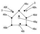
도 48은, 블록의 형상이 격자모양 이외인 블록에 대하여, 방향을 정의한 것이다.Fig. 48 defines the directions of blocks in which the shape of the block is other than the lattice shape.
동도에 있어서, 먼저 기준점(48a)~(48e)이 배치되어 있다. 이 기준점(48a)~(48e)을 연결하는 선에 의하여 블록의 방향을 나타내는 형상(여기에서는 상방으로 향한 5각형)이 정의되어 있다. 따라서, 이 기준점을 바탕으로 가상 기준점(48f), (48g), (48h)이 배치되고, 이 가상 기준점을 시점으로 하여 방향과 길이를 갖는 벡터 종점에 정보 도트(3)가 배치되어 있다. 이와 같이, 동도에서는, 블록의 방향을 기준점 배치 방법에 의하여 정의할 수 있다. 그리고 블록의 방향이 정의됨으로써, 블록 전체의 크기도 정의되게 된다.In the figure,
도 48에 있어서는, 기준점(48a)~(48e)과 정보 도트(3)는 모두 동일한 형상의 것으로 설명했으나, 예를 들면 도 57에 나타낸 바와 같이, 기준점(48a)~(48e)을 정보 도트(3)보다 큰 형상으로 해도 된다. 또한, 이 기준점(48a)~(48e)과 정보 도트(3)와는 식별 가능하다면 어떠한 형상으로 해도 되며, 삼각형, 사각형 그 이상의 다각형이라도 된다.In FIG. 48, the
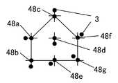
도 49는, 도 48에 나타낸 블록을 종횡 방향으로 2 개씩 연결한 것이다.FIG. 49 connects the blocks shown in FIG. 48 two by one in the vertical and horizontal directions.
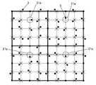
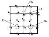
도 50 및 도 51은, 블록의 형상을 격자상, 즉 사각형 영역으로 하지 않고, 일부의 기준점과 가상 기준점을 일치시켰을 경우를 나타낸 것이다.50 and 51 show a case where a part of the reference point and the virtual reference point coincide without making the shape of the block into a lattice shape, that is, a rectangular area.
즉, 도 48에 있어서 배치되어 있는 (48a), (48b), (48c), (48d), (48e), (48f), (48g)는, 기준점인 것과 동시에 가상 기준점이라고 간주할 수 있다. 그 때문에 도 50에서는, 각 점을 시점으로 한 벡터의 종점에 정보 도트(3)를 배치하고 있다. 그리고, (48a), (48b), (48c), (48f), (48g)로 구성되는 5각형에 대하여, (48c)가 정점이므로, 상기 블록이 상향인 것을 인식할 수 있다.That is, the 48th, 48b, 48c, 48d, 48e, 48f, and 48g arranged in FIG. 48 can be regarded as virtual reference points as well as reference points. Therefore, in FIG. 50, the information dot 3 is arrange | positioned at the end point of the vector which made each point the starting point. For the pentagon consisting of (48a), (48b), (48c), (48f) and (48g), since (48c) is a vertex, it can be recognized that the block is upward.
도 51은, 도 50에 나타낸 블록을 종횡 방향으로 2 개씩 연결한 것이다.FIG. 51 connects the blocks shown in FIG. 50 two by one in the vertical and horizontal directions.
도 52 및 도 53은, 그 외의 것과는 다른 방향 기준으로 정보 도트를 배치함으로써, 블록의 방향을 정의하는 경우를 나타내고 있다.52 and 53 show the case where the direction of the block is defined by arranging the information dots on a direction different from the others.
동도에서는, 블록의 네 모퉁이에 기준점이 배치되어 있다. 가상 기준점을 중심으로 배치되는 정보 도트(3) 중, 디렉션 영역(21a)에 있어서 정보 도트(3)의 방향을, 그 외의 정보 도트의 방향 기준과 다르게 함으로써 방향을 정의한다. 즉, 디렉션 영역(21a)만 가상 기준점으로부터 종횡 방향으로 어긋난 위치에 정보 도트(3)를 배치하고, 그 이외의 영역에서는 정보 도트(3)는 가상 기준점으로부터 사선 방향으로 어긋난 위치에 배치되어 있다. 도 52에서는, 디렉션 영역(21a)이 블록 중심으로부터 상방으로 어긋난 위치(+y 방향)에 배치되고 있으므로, 상기 블록은 상향인 것을 알 수 있다. 이와 같이 디렉션 영역(21a)의 블록 내의 위치로 블록의 방향 을 정의했을 경우에는, 디렉션 영역(21a) 내의 정보 도트(3)의 배치는 임의이다. 즉 동도에서는, 정보 도트(3)는, 가상 기준점보다 우방향의 벡터 종점에 배치되어 있다.In the same drawing, a reference point is arranged at four corners of the block. In the information dot 3 arrange | positioned centering on a virtual reference point, the direction is defined by making the direction of the information dot 3 different from the direction reference of the other information dot in the direction area |
도 53은, 도 52에 나타낸 블록을 종횡 방향으로 2 개씩 연결한 것이다.FIG. 53 connects the blocks shown in FIG. 52 two by one in the vertical and horizontal directions.
도 54 및 도 55는, 복수의 영역에 있어서, 그 외의 것과는 다른 방향 기준으로 정보 도트를 배치함으로써, 블록의 방향을 정의하는 경우를 나타내고 있다.54 and 55 show a case where the direction of the block is defined by arranging information dots on a direction different from the others in a plurality of areas.
동도에서는, 블록의 4 모퉁이에 기준점이 배치되어 있다. 상기 블록에 대하여, 가상 기준점을 중심으로 배치되는 정보 도트(3) 중, 3 개소의 정보 도트(3)의 배치에 있어서 방향 기준을 그 외의 영역과 다르게 함으로써, 이 3개소를 디렉션 영역(21a)으로 하고, 이 디렉션 영역(21a)을 연결하는 선의 형상으로 블록의 방향을 정의한 것이다. 즉 동도에서는 삼각형의 형상으로부터 상기 블록이 상향인 것이 식별할 수 있다.In the same drawing, a reference point is arranged at four corners of the block. In the arrangement of the three
도 55는, 도 54에 나타낸 블록을 종횡 방향으로 2 개씩 연결한 것이다.FIG. 55 connects the blocks shown in FIG. 54 two by one in the vertical and horizontal directions.
도 56은, 기준점(4a)을 격자점과 일치시켰을 경우로서, 이와 같이 블록 중심을 기준으로 점대칭이 되지 않도록 기준점(4a)을 배치한 경우에는, 굳이 디렉션 영역이나 디렉션 도트를 배치하지 않고, 그대로 블록의 방향을 정의할 수 있다.FIG. 56 shows the case where the
도 57은 도 48에 나타낸 도트 패턴의 기준점(48a)~(48g)의 도트의 크기를 다른 정보 도트(3)보다 크게 한 것이다.FIG. 57 shows that the size of the dots of the
본 실시 형태에서는, 정보 도트, 디렉션 도트, 기준 도트의 각 도트는 원형의 것을 사용하여 설명했으나, 그에 국한하지 않고, 비원형인 삼각형, 사각형 또는 그 이상의 다각형이라도 무방하다.In the present embodiment, each dot of the information dot, the direction dot, and the reference dot has been described using a circular one, but the present invention is not limited thereto, and may be a non-circular triangle, a square, or a polygon.
도 58은, 1개소의 기준 도트(58a)만을 다른 기준 도트(58b)~(58d)보다도 큰 도트로 함으로써, 이 대형(大形)인 기준 도트(58a)가 배치된 방향으로 블록의 방향을 정의한 것이다. 이 기준 도트(58a)에 대해서도, 형상이나 크기를 변경하여도 됨은 물론이다. 또한, 기준 도트(58a)를 배치하지 않음으로써 블록의 방향을 정의해도 된다. 또한, 이와 같이 크기를 변경한 도트를 배치하여 블록의 방향을 정의하는 경우, 상기 도트는 반드시 기준 도트일 필요는 없고, 정보 도트(3)라도 무방하다. 정보 도트(3)의 크기를 변경함으로써 블록의 방향을 정의하는 경우에는, 정보 도트(3)의 정보를 희생하지 않고 블록의 방향을 정의할 수 있다.58 shows only one
도 59는, 디렉션 도트(21)의 크기를 다른 정보 도트(3) 또는 기준 격자점 도트(4)보다 크게 함으로써 상기 도트가 디렉션 도트(21)인 것을 식별 가능할 수 있도록 한 것이다. 이와 같이 디렉션 도트(21)의 크기를 다른 정보 도트와 다르게 함으로써, 정보 도트(3)의 방향 기준이 디렉션 도트(21)의 방향 기준과 같더라도(도 59에서는 양자 모두의 종횡 방향이 되어 있다), 블록의 방향을 정의할 수게 된다.59 shows that the dot is the direction dot 21 by making the size of the direction dot 21 larger than the other information dot 3 or the reference
도 62는, 블록의 중앙 상방의 격자 영역에 정보 도트를 배치하지 않는 구성을 나타내고 있다. 이와 같이 소정의 격자 영역(가상 격자점상 또는 기준점)에 정보 도트(3)를 배치하지 않음으로써 그 격자 영역의 위치에 따라 블록의 방향을 정의할 수 있게 된다. 동도에서는, 상향인 블록인 것을 알 수 있다.Fig. 62 shows a configuration in which no information dot is arranged in the lattice area above the center of the block. As such, by not disposing the information dot 3 in a predetermined lattice region (on a virtual lattice point or a reference point), the direction of the block can be defined according to the position of the lattice region. In the figure, it can be seen that the block is upward.
또한, 도 63은, 블록의 중앙 상방의 가상 격자점 상에 정보 도트(3)를 배치함으로써 블록의 방향을 정의한 경우의 예이다.63 is an example in which the direction of the block is defined by arranging the
도 60은, 격자 영역 내에 배치되는 정보 도트의 형상을 복수의 형상으로 표현한 것이다. 동도에 나타낸 바와 같이, 정보 도트의 형상은, ■, ▲, ●를 선택적으로 배치하고 있고, 이 형상마다 다른 정보를 정의하여도 된다.60 expresses the shape of the information dot disposed in the lattice area in a plurality of shapes. As shown in the figure, the shape of the information dot selectively arranges ■, ,, ●, and may define different information for each of these shapes.
또한, 동도에 있어서, 블록의 방향은, 4 모퉁이의 기준 격자점 도트 중 2개를 기준 격자점으로부터 옮겨 배치함으로써 정의할 수 있다. 동도에서는 블록의 좌상과 우상의 기준 격자점 도트를 상방으로 옮기고 있기 때문에, 상기 블록은 상향이라고 식별할 수 있다.In addition, in the same drawing, the direction of the block can be defined by moving two of the four reference grid point dots from the reference grid point. In the same figure, since the reference grid point dots of the upper left and upper right of the block are moved upward, the block can be identified as upward.
도 61은, 블록의 중앙 격자 영역의 가상 격자점에 배치되는 정보 도트(3)에 대하여만 다른 정보 도트와 형상을 다르게 한 것이다. 이 가상 격자점에는 삼각형의 정보 도트가 배치되고 있어, 상기 삼각형의 형상에 의하여, 상기 블록이 상향인 것을 인식할 수 있도록 되어 있다.61 differs in shape from other information dots only with respect to the information dot 3 arranged in the virtual lattice point of the center lattice area of the block. A triangular information dot is arranged at this virtual grid point, and the shape of the triangle makes it possible to recognize that the block is upward.
본 발명은, 광학 센서로 읽어냄으로써 음악이나 음성을 출력할 수 있는 그림책, 사진, 카드게임, 안전 시스템(security system) 등에 넓게 이용할 수 있다.INDUSTRIAL APPLICABILITY The present invention can be widely used for a picture book, a photo, a card game, a security system, and the like, which can output music or sound by reading with an optical sensor.
Claims (18)
Translated fromKoreanApplications Claiming Priority (2)
| Application Number | Priority Date | Filing Date | Title |
|---|---|---|---|
| JPJP-P-2005-00194295 | 2005-07-01 | ||
| JP2005194295AJP3771252B1 (en) | 2005-07-01 | 2005-07-01 | Dot pattern |
Publications (2)
| Publication Number | Publication Date |
|---|---|
| KR20070114842Atrue KR20070114842A (en) | 2007-12-04 |
| KR100935345B1 KR100935345B1 (en) | 2010-01-06 |
Family
ID=36383733
Family Applications (1)
| Application Number | Title | Priority Date | Filing Date |
|---|---|---|---|
| KR1020077024724AExpired - Fee RelatedKR100935345B1 (en) | 2005-07-01 | 2006-06-30 | Dot pattern |
Country Status (14)
| Country | Link |
|---|---|
| US (3) | US8430328B2 (en) |
| EP (2) | EP2439677B1 (en) |
| JP (1) | JP3771252B1 (en) |
| KR (1) | KR100935345B1 (en) |
| CN (2) | CN101213564B (en) |
| AU (1) | AU2006266517B2 (en) |
| BR (1) | BRPI0612755B1 (en) |
| CA (1) | CA2613046C (en) |
| IL (1) | IL188225A (en) |
| MX (1) | MX352384B (en) |
| MY (1) | MY164588A (en) |
| RU (1) | RU2439699C2 (en) |
| TW (3) | TWI618000B (en) |
| WO (1) | WO2007004994A1 (en) |
Cited By (1)
| Publication number | Priority date | Publication date | Assignee | Title |
|---|---|---|---|---|
| KR20220045365A (en)* | 2020-10-05 | 2022-04-12 | 에르미 주식회사 | Dot pattern and method for recognizing dot pattern |
Families Citing this family (51)
| Publication number | Priority date | Publication date | Assignee | Title |
|---|---|---|---|---|
| MXPA05003310A (en) | 2002-09-26 | 2005-10-18 | Yoshida Kenji | Information reproduction/i/o method using dot pattern, information reproduction device, mobile information i/o device, and electronic toy. |
| US8237983B2 (en)* | 2004-12-28 | 2012-08-07 | Kenji Yoshida | Information input output method using dot pattern |
| CA2606135C (en) | 2005-04-28 | 2015-06-30 | Kenji Yoshida | Information input/output method using dot pattern |
| JP3771252B1 (en)* | 2005-07-01 | 2006-04-26 | 健治 吉田 | Dot pattern |
| JP3830956B1 (en)* | 2005-09-14 | 2006-10-11 | 健治 吉田 | Information output device |
| EP1983412A4 (en)* | 2006-01-31 | 2011-07-20 | Kenji Yoshida | Image processing method |
| TWI370413B (en) | 2006-04-14 | 2012-08-11 | Sonix Technology Co Ltd | Graphical indicator |
| US7445160B2 (en)* | 2006-06-14 | 2008-11-04 | Hewlett-Packard Development Company, L.P. | Position location using error correction |
| US20080252916A1 (en)* | 2007-04-13 | 2008-10-16 | Etoms Electronics Corp. | Information reproduction method and device using dot pattern and dot pattern thereof |
| CN101849243B (en)* | 2007-10-30 | 2014-05-28 | 吉田健治 | Code pattern |
| AU2007254595B2 (en)* | 2007-12-20 | 2011-04-07 | Canon Kabushiki Kaisha | Constellation detection |
| DE102008017168A1 (en)* | 2008-04-02 | 2009-10-08 | Crossmedia Solution Gmbh & Co. Kg | Method for storing and reading data |
| KR100968255B1 (en) | 2008-07-01 | 2010-07-06 | 이병진 | Contact card recognition system and recognition method using touch screen |
| EP2312375A4 (en) | 2008-07-15 | 2012-10-10 | Kenji Yoshida | Naked eye three-dimensional video image display system, naked eye three-dimensional video image display device, amusement game machine and parallax barrier sheet |
| TWI397013B (en)* | 2008-09-26 | 2013-05-21 | Elan Microelectronics Corp | The dot code pattern and the dot code group pattern and the image processing circuit of the density coding type |
| CN101727596B (en)* | 2008-10-13 | 2013-09-18 | 义隆电子股份有限公司 | Dot code pattern and image processing device for processing dot code pattern |
| CN101727595B (en)* | 2008-10-13 | 2012-09-26 | 义隆电子股份有限公司 | Dot code pattern and dot code group pattern and its image processing circuit |
| US9010640B2 (en) | 2009-07-13 | 2015-04-21 | Kenji Yoshida | Stream dot pattern, method of forming stream dot pattern, information input/output method using stream dot pattern, and dot pattern |
| US9749607B2 (en) | 2009-07-16 | 2017-08-29 | Digimarc Corporation | Coordinated illumination and image signal capture for enhanced signal detection |
| JP2011053854A (en)* | 2009-09-01 | 2011-03-17 | Hong-Teng Lv | Coding method of two-dimensional optical recognition code and print product using the method |
| US8218004B2 (en)* | 2009-10-22 | 2012-07-10 | Cycling & Health Tech Industry R&D Center | Displacement sensing system |
| KR100991878B1 (en)* | 2009-10-22 | 2010-11-04 | 장효선 | Code decoding method being indicated on printed object |
| JP5604761B2 (en) | 2009-11-11 | 2014-10-15 | 健治 吉田 | Print medium, information processing method, information processing apparatus |
| JP5277403B2 (en)* | 2010-01-06 | 2013-08-28 | 健治 吉田 | Curved body for information input, map for information input, drawing for information input |
| TWI439943B (en)* | 2010-04-27 | 2014-06-01 | Shou Te Wei | Encoding structure for dot pattern, its decoding method and electronic device |
| US9576230B2 (en)* | 2010-07-06 | 2017-02-21 | Marcelo Amaral Rezende | Dot code pattern for absolute position and other information using an optical pen, process of printing the dot code, process of reading the dot code |
| JP5315512B2 (en) | 2010-12-09 | 2013-10-16 | 健治 吉田 | Machine readable dot pattern |
| WO2013027234A1 (en)* | 2011-08-22 | 2013-02-28 | Zak株式会社 | Satellite dot type two-dimensional code and method for reading same |
| CN103390183B (en)* | 2012-05-09 | 2019-07-19 | 顾泽苍 | A kind of generation method of the anti-counterfeiting codes suitable for handset identity |
| JP5344328B1 (en)* | 2012-10-01 | 2013-11-20 | 健治 吉田 | Dot pattern, dot pattern forming medium, dot pattern image data generating program, dot pattern forming device, optical device, optical reader, information input / output device, dot pattern reader |
| KR102076233B1 (en) | 2012-12-05 | 2020-02-11 | 가부시키가이샤 아이피솔루션즈 | Facility-management-system control interface |
| TWI489352B (en)* | 2013-08-13 | 2015-06-21 | Wistron Corp | Optical touch positioning method, system and optical touch positioner |
| US9635378B2 (en) | 2015-03-20 | 2017-04-25 | Digimarc Corporation | Sparse modulation for robust signaling and synchronization |
| US10424038B2 (en) | 2015-03-20 | 2019-09-24 | Digimarc Corporation | Signal encoding outside of guard band region surrounding text characters, including varying encoding strength |
| TWI492167B (en) | 2014-06-05 | 2015-07-11 | Sonix Technology Co Ltd | Graphical indicator |
| EP3045214A1 (en) | 2015-01-14 | 2016-07-20 | Cartamundi Turnhout N.V. | Board game with pattern recognition |
| US10783601B1 (en) | 2015-03-20 | 2020-09-22 | Digimarc Corporation | Digital watermarking and signal encoding with activable compositions |
| WO2016153936A1 (en) | 2015-03-20 | 2016-09-29 | Digimarc Corporation | Digital watermarking and data hiding with narrow-band absorption materials |
| ES2724010T3 (en)* | 2015-04-30 | 2019-09-05 | Nestle Sa | Code and system container for preparing a beverage or food |
| WO2017007483A1 (en)* | 2015-07-09 | 2017-01-12 | Hewlett-Packard Development Company, L.P. | Multi-dimensional cyclic symbols |
| TWI545504B (en) | 2015-08-31 | 2016-08-11 | 原相科技股份有限公司 | Decoding method using patterns and system thereof |
| US9600700B1 (en) | 2015-08-31 | 2017-03-21 | Pixart Imaging Inc. | Portable electronic device and operation method thereof |
| US9805239B2 (en) | 2015-08-31 | 2017-10-31 | Pixart Imagine Inc. | QR code detecting device and operation method thereof |
| CN109359657B (en) | 2015-10-19 | 2022-11-25 | 松翰科技股份有限公司 | Index structure |
| US10896307B2 (en) | 2017-11-07 | 2021-01-19 | Digimarc Corporation | Generating and reading optical codes with variable density to adapt for visual quality and reliability |
| US11062108B2 (en) | 2017-11-07 | 2021-07-13 | Digimarc Corporation | Generating and reading optical codes with variable density to adapt for visual quality and reliability |
| US10872392B2 (en) | 2017-11-07 | 2020-12-22 | Digimarc Corporation | Generating artistic designs encoded with robust, machine-readable data |
| KR102066391B1 (en)* | 2017-11-16 | 2020-01-15 | 상명대학교산학협력단 | Data embedding appratus for multidimensional symbology system based on 3-dimension and data embedding method for the symbology system |
| KR102104027B1 (en)* | 2018-08-30 | 2020-04-23 | 선문대학교 산학협력단 | Mesh structure indicating information and touch device having sensing electrode made of the mesh structure |
| US20220398769A1 (en)* | 2019-10-31 | 2022-12-15 | Hewlett-Packard Development Company, L.P. | Recovering alignment grids |
| US12361248B2 (en) | 2023-05-19 | 2025-07-15 | Aires Investment Holdings Private Limited | Two-dimensional code and method and system for generating and reading thereof |
Family Cites Families (93)
| Publication number | Priority date | Publication date | Assignee | Title |
|---|---|---|---|---|
| US4263504A (en) | 1979-08-01 | 1981-04-21 | Ncr Corporation | High density matrix code |
| US4604065A (en) | 1982-10-25 | 1986-08-05 | Price/Stern/Sloan Publishers, Inc. | Teaching or amusement apparatus |
| JPS6165213A (en) | 1984-09-06 | 1986-04-03 | Canon Inc | Optical system for autofocus |
| US4627819A (en) | 1985-01-23 | 1986-12-09 | Price/Stern/Sloan Publishers, Inc. | Teaching or amusement apparatus |
| US4924078A (en) | 1987-11-25 | 1990-05-08 | Sant Anselmo Carl | Identification symbol, system and method |
| US5124536A (en) | 1988-05-05 | 1992-06-23 | International Data Matrix, Inc. | Dynamically variable machine readable binary code and method for reading and producing thereof |
| US4939354A (en) | 1988-05-05 | 1990-07-03 | Datacode International, Inc. | Dynamically variable machine readable binary code and method for reading and producing thereof |
| US5591957A (en) | 1988-08-12 | 1997-01-07 | Casio Computer Co., Ltd. | Apparatus for reading mesh pattern image data having bars along upper and lower sides of mesh pattern and a boundary line between horizontally adjacent dark and light area of mesh pattern |
| US5042079A (en) | 1988-08-12 | 1991-08-20 | Casio Computer Co., Ltd. | Method of recording/reproducing data of mesh pattern, and apparatus therefor |
| US5051736A (en) | 1989-06-28 | 1991-09-24 | International Business Machines Corporation | Optical stylus and passive digitizing tablet data input system |
| US5128528A (en)* | 1990-10-15 | 1992-07-07 | Dittler Brothers, Inc. | Matrix encoding devices and methods |
| FR2684214B1 (en) | 1991-11-22 | 1997-04-04 | Sepro Robotique | INDEXING CARD FOR GEOGRAPHIC INFORMATION SYSTEM AND SYSTEM INCLUDING APPLICATION. |
| US5852434A (en) | 1992-04-03 | 1998-12-22 | Sekendur; Oral F. | Absolute optical position determination |
| JPH10187907A (en) | 1992-09-28 | 1998-07-21 | Olympus Optical Co Ltd | Dot code |
| AU668987B2 (en) | 1992-09-28 | 1996-05-23 | Olympus Optical Co., Ltd. | Dot code and information recording/reproducing system for recording/reproducing dot code |
| US5416312A (en) | 1992-11-20 | 1995-05-16 | Cherloc | Document bearing an image or a text and provided with an indexing frame, and associated document analysis system |
| RU2126598C1 (en) | 1993-11-16 | 1999-02-20 | Кузнецов Юрий Вениаминович | Method and device for adaptive rendering of half-tone images |
| JP3277052B2 (en) | 1993-11-19 | 2002-04-22 | シャープ株式会社 | Coordinate input device and coordinate input method |
| JPH07178257A (en) | 1993-12-24 | 1995-07-18 | Casio Comput Co Ltd | Audio output device |
| JPH07296387A (en) | 1994-04-22 | 1995-11-10 | Olympus Optical Co Ltd | Information recording medium |
| JPH0837567A (en) | 1994-07-26 | 1996-02-06 | Olympus Optical Co Ltd | Information recording medium and information reproducing device |
| JP2912831B2 (en) | 1994-10-05 | 1999-06-28 | オリンパス光学工業株式会社 | Information recording medium and information reproducing apparatus |
| JP3639328B2 (en)* | 1994-10-14 | 2005-04-20 | オリンパス株式会社 | Information recording medium, two-dimensional code, information reproducing system, and information reproducing method |
| US5661506A (en) | 1994-11-10 | 1997-08-26 | Sia Technology Corporation | Pen and paper information recording system using an imaging pen |
| JP2952170B2 (en) | 1994-12-16 | 1999-09-20 | オリンパス光学工業株式会社 | Information reproduction system |
| TW331000B (en)* | 1994-12-28 | 1998-05-01 | Eten Information System Co Ltd | Method for determining crossing points of two overlapping figures |
| JP3523710B2 (en) | 1995-04-04 | 2004-04-26 | オリンパス株式会社 | Information reproduction system, recording medium, recording device, and recording method |
| GB9507098D0 (en) | 1995-04-06 | 1995-05-31 | Rolls Royce Plc | Process and apparatus for reading a dot matrix code marking of an article |
| JPH0944591A (en) | 1995-08-03 | 1997-02-14 | Olympus Optical Co Ltd | Code sheet and information reproducing device |
| JPH09114951A (en) | 1995-10-23 | 1997-05-02 | Olympus Optical Co Ltd | Information recording medium |
| JPH09185488A (en) | 1995-12-27 | 1997-07-15 | Tetsuya Fuchiguchi | Multimedia doll system |
| JP3956419B2 (en) | 1997-03-06 | 2007-08-08 | 凸版印刷株式会社 | ID card creation method, ID card and ID card information reading method |
| JPH10326331A (en)* | 1997-03-24 | 1998-12-08 | Olympus Optical Co Ltd | Recording medium with dot code, and code reader |
| JPH10326323A (en) | 1997-03-24 | 1998-12-08 | Olympus Optical Co Ltd | Code pattern image recording device |
| US6012961A (en) | 1997-05-14 | 2000-01-11 | Design Lab, Llc | Electronic toy including a reprogrammable data storage device |
| JPH10320497A (en) | 1997-05-16 | 1998-12-04 | Olympus Optical Co Ltd | Code reading and recording device |
| JP3953144B2 (en) | 1997-07-16 | 2007-08-08 | オリンパス株式会社 | Code image quality inspection system |
| EP0921675B1 (en) | 1997-12-03 | 2006-07-05 | Kabushiki Kaisha Toshiba | Method of processing image information and method of preventing forgery of certificates or the like |
| JP3959817B2 (en) | 1998-01-07 | 2007-08-15 | 富士ゼロックス株式会社 | Image forming apparatus |
| JPH11219405A (en) | 1998-02-02 | 1999-08-10 | Olympus Optical Co Ltd | Information reproducing system |
| WO1999050736A1 (en) | 1998-04-01 | 1999-10-07 | Xerox Corporation | Paper indexing of recordings |
| JP3458737B2 (en) | 1998-11-27 | 2003-10-20 | 株式会社デンソー | Reading method of two-dimensional code and recording medium |
| JP2000285225A (en) | 1999-03-30 | 2000-10-13 | Kiyoyuki Horii | Method for processing image by computer |
| RU2166207C2 (en) | 1999-04-08 | 2001-04-27 | Закрытое акционерное общество "Аби Программное обеспечение" | Method for using auxiliary data arrays in conversion and/or verification of character-expressed computer codes and respective subpictures |
| GB2349836A (en) | 1999-04-23 | 2000-11-15 | Tri State | Talking doll with bar-code optical reader |
| JP2000325668A (en) | 1999-05-14 | 2000-11-28 | T Shot:Kk | Reactive talking toy system |
| AUPQ363299A0 (en) | 1999-10-25 | 1999-11-18 | Silverbrook Research Pty Ltd | Paper based information inter face |
| US6728000B1 (en) | 1999-05-25 | 2004-04-27 | Silverbrook Research Pty Ltd | Method and system for printing a document |
| US6830196B1 (en) | 1999-05-25 | 2004-12-14 | Silverbrook Research Pty Ltd | Identity-coded surface region |
| JP4785310B2 (en) | 1999-05-28 | 2011-10-05 | アノト アクティエボラーク | Products used to record information |
| JP3764100B2 (en) | 1999-05-28 | 2006-04-05 | アノト アイ ピー リック エイチ ビー | Calendar book |
| EP1188142A1 (en) | 1999-05-28 | 2002-03-20 | Anoto AB | Recording of information |
| SE516522C2 (en) | 1999-05-28 | 2002-01-22 | Anoto Ab | Position determining product for digitization of drawings or handwritten information, obtains displacement between symbol strings along symbol rows when symbol strings are repeated on symbol rows |
| JP2001052104A (en) | 1999-08-05 | 2001-02-23 | Olympus Optical Co Ltd | Data recording method, data reproducing method and data recording medium |
| SE0000939L (en) | 2000-02-18 | 2001-08-19 | Anoto Ab | Inenhetsarrangemang |
| US6533182B1 (en)* | 1999-09-21 | 2003-03-18 | Omron Corporation | Two-dimensional dot code and reader thereof |
| SE517445C2 (en) | 1999-10-01 | 2002-06-04 | Anoto Ab | Position determination on a surface provided with a position coding pattern |
| MXPA02006340A (en) | 1999-12-23 | 2002-12-13 | Anoto Ab | General information management system. |
| US6244764B1 (en) | 2000-01-21 | 2001-06-12 | Robotic Vision Systems, Inc. | Method for data matrix print quality verification |
| WO2001059643A1 (en) | 2000-02-10 | 2001-08-16 | Sony Corporation | Automatic device, information providing device, robot device, and transaction method |
| US7050653B2 (en) | 2000-04-05 | 2006-05-23 | Anoto Ab | Identification of virtual raster pattern |
| US6586688B2 (en) | 2000-04-05 | 2003-07-01 | Anoto Ab | Information-related devices and methods |
| JP2001287330A (en) | 2000-04-10 | 2001-10-16 | Olympus Optical Co Ltd | Method and apparatus for forming image data of optically readable dots and recording medium |
| JP2001318926A (en) | 2000-05-11 | 2001-11-16 | Yazaki Corp | Information management device and information management system using the device |
| JP2002041199A (en) | 2000-05-15 | 2002-02-08 | Pasukaru:Kk | Operation processing method for computer device using shortcut symbol, and shortcut processing system |
| JP2001334012A (en) | 2000-05-29 | 2001-12-04 | Creatures Inc | Game system using game card, game card used therefor, and game information storage medium used therefor |
| JP3837999B2 (en) | 2000-06-05 | 2006-10-25 | 富士ゼロックス株式会社 | Image generation method and image generation apparatus |
| JP2002002024A (en) | 2000-06-26 | 2002-01-08 | Olympus Optical Co Ltd | Method and apparatus for printing code and recording medium |
| AU2001284468A1 (en) | 2000-09-12 | 2002-03-26 | Omron Corporation | Dot code and dot code reader |
| JP4567860B2 (en) | 2000-09-12 | 2010-10-20 | 任天堂株式会社 | Code reader, recording medium, electronic device, data transmission / reception system, and data transmission / reception method |
| JP2002205291A (en) | 2000-10-23 | 2002-07-23 | Sony Corp | Leg type robot and movement control method for leg type robot, as well as recording medium |
| JP2002149331A (en) | 2000-11-15 | 2002-05-24 | Canon Inc | Coordinate plate, coordinate input device, coordinate input / output device |
| US6633008B2 (en) | 2001-02-27 | 2003-10-14 | Weigh-Tronix, Inc. | Electronic force sensing shock resistant load cell |
| JP4763905B2 (en) | 2001-03-06 | 2011-08-31 | オリンパス株式会社 | Encoded image reader |
| US7649637B2 (en) | 2001-04-05 | 2010-01-19 | Anoto Ab | Method for printing a global position-coding pattern |
| US6732927B2 (en) | 2001-06-26 | 2004-05-11 | Anoto Ab | Method and device for data decoding |
| SE520682C2 (en) | 2001-12-06 | 2003-08-12 | Anoto Ab | Reconstruction of a virtual screen |
| TWI235926B (en) | 2002-01-11 | 2005-07-11 | Sonix Technology Co Ltd | A method for producing indicators and processing system, coordinate positioning system and electronic book system utilizing the indicators |
| MXPA05003310A (en)* | 2002-09-26 | 2005-10-18 | Yoshida Kenji | Information reproduction/i/o method using dot pattern, information reproduction device, mobile information i/o device, and electronic toy. |
| SE0203853D0 (en) | 2002-12-23 | 2002-12-23 | Anoto Ab | Data code |
| CN100361144C (en) | 2003-03-17 | 2008-01-09 | 吉田健治 | Information input/output method using dot pattern |
| JP3902163B2 (en) | 2003-07-11 | 2007-04-04 | 大日本印刷株式会社 | Related form determination system, electronic pen and program |
| JP4200106B2 (en) | 2003-07-15 | 2008-12-24 | 株式会社リコー | Image processing apparatus, image processing method, computer program, and storage medium for storing computer program |
| AU2003292817A1 (en) | 2003-12-25 | 2005-07-21 | Kenji Yoshida | Method for inputting/outputting information using dot pattern |
| US8237983B2 (en) | 2004-12-28 | 2012-08-07 | Kenji Yoshida | Information input output method using dot pattern |
| JPWO2006112021A1 (en) | 2005-04-15 | 2008-11-27 | 吉田 健治 | Information input / output method using dot pattern |
| CA2606135C (en) | 2005-04-28 | 2015-06-30 | Kenji Yoshida | Information input/output method using dot pattern |
| JP3771252B1 (en) | 2005-07-01 | 2006-04-26 | 健治 吉田 | Dot pattern |
| JP4810918B2 (en) | 2005-08-01 | 2011-11-09 | 富士ゼロックス株式会社 | Code pattern image generating apparatus and method, code pattern image reading apparatus and method, and code pattern image medium |
| AU2006252254B2 (en) | 2006-12-22 | 2009-03-05 | Canon Kabushiki Kaisha | Multiple barcode detection |
| AU2006252239B2 (en) | 2006-12-22 | 2010-04-01 | Canon Kabushiki Kaisha | Barcode pattern |
| US20080252916A1 (en) | 2007-04-13 | 2008-10-16 | Etoms Electronics Corp. | Information reproduction method and device using dot pattern and dot pattern thereof |
| TWI391862B (en)* | 2008-06-06 | 2013-04-01 | Elan Microelectronics Corp | A two-dimensional dot code, a decoding apparatus, and a method thereof |
- 2005
- 2005-07-01JPJP2005194295Apatent/JP3771252B1/ennot_activeExpired - Lifetime
- 2006
- 2006-06-29TWTW105117035Apatent/TWI618000B/ennot_activeIP Right Cessation
- 2006-06-29TWTW95123589Apatent/TWI446279B/ennot_activeIP Right Cessation
- 2006-06-29TWTW103119047Apatent/TWI550528B/ennot_activeIP Right Cessation
- 2006-06-30MYMYPI20063148Apatent/MY164588A/enunknown
- 2006-06-30MXMX2007016474Apatent/MX352384B/enactiveIP Right Grant
- 2006-06-30EPEP11175120.2Apatent/EP2439677B1/ennot_activeNot-in-force
- 2006-06-30KRKR1020077024724Apatent/KR100935345B1/ennot_activeExpired - Fee Related
- 2006-06-30CNCN2006800235674Apatent/CN101213564B/ennot_activeExpired - Fee Related
- 2006-06-30RURU2008102706Apatent/RU2439699C2/ennot_activeIP Right Cessation
- 2006-06-30WOPCT/SG2006/000185patent/WO2007004994A1/enactiveApplication Filing
- 2006-06-30CNCN201210025984.XApatent/CN102722267B/ennot_activeExpired - Fee Related
- 2006-06-30BRBRPI0612755-0Apatent/BRPI0612755B1/ennot_activeIP Right Cessation
- 2006-06-30USUS11/993,527patent/US8430328B2/ennot_activeExpired - Fee Related
- 2006-06-30EPEP06748126.7Apatent/EP1899900B1/ennot_activeRevoked
- 2006-06-30CACA2613046Apatent/CA2613046C/ennot_activeExpired - Fee Related
- 2006-06-30AUAU2006266517Apatent/AU2006266517B2/ennot_activeCeased
- 2007
- 2007-12-18ILIL188225Apatent/IL188225A/ennot_activeIP Right Cessation
- 2013
- 2013-04-29USUS13/872,555patent/US9400951B2/ennot_activeExpired - Fee Related
- 2016
- 2016-07-25USUS15/218,841patent/US20160335528A1/ennot_activeAbandoned
Cited By (1)
| Publication number | Priority date | Publication date | Assignee | Title |
|---|---|---|---|---|
| KR20220045365A (en)* | 2020-10-05 | 2022-04-12 | 에르미 주식회사 | Dot pattern and method for recognizing dot pattern |
Also Published As
Similar Documents
| Publication | Publication Date | Title |
|---|---|---|
| KR100935345B1 (en) | Dot pattern | |
| US8253982B2 (en) | Information input/output method using dot pattern | |
| JP3706385B2 (en) | Information input / output method using dot pattern | |
| JP4336837B2 (en) | Dot pattern | |
| JP4142683B2 (en) | Dot pattern | |
| KR100906457B1 (en) | Information input/output method using dot pattern | |
| KR20050028040A (en) | Method for inputting and outputting information using dot pattern | |
| JP3858052B1 (en) | Information input / output method using dot pattern | |
| JP3858052B6 (en) | Information input / output method using dot pattern | |
| CN101872411A (en) | Encoding method, decoding method, and encoding and decoding method of microcode array | |
| KR20070112474A (en) | Information input / output method using dot pattern | |
| AU2012204140A1 (en) | Dot pattern | |
| AU2016200846A1 (en) | Printed Material Printed with a Dot Pattern |
Legal Events
| Date | Code | Title | Description |
|---|---|---|---|
| A201 | Request for examination | ||
| PA0105 | International application | St.27 status event code:A-0-1-A10-A15-nap-PA0105 | |
| PA0201 | Request for examination | St.27 status event code:A-1-2-D10-D11-exm-PA0201 | |
| P11-X000 | Amendment of application requested | St.27 status event code:A-2-2-P10-P11-nap-X000 | |
| P18-X000 | Priority claim added or amended | St.27 status event code:A-2-2-P10-P18-nap-X000 | |
| PG1501 | Laying open of application | St.27 status event code:A-1-1-Q10-Q12-nap-PG1501 | |
| E902 | Notification of reason for refusal | ||
| PE0902 | Notice of grounds for rejection | St.27 status event code:A-1-2-D10-D21-exm-PE0902 | |
| P11-X000 | Amendment of application requested | St.27 status event code:A-2-2-P10-P11-nap-X000 | |
| P13-X000 | Application amended | St.27 status event code:A-2-2-P10-P13-nap-X000 | |
| E902 | Notification of reason for refusal | ||
| PE0902 | Notice of grounds for rejection | St.27 status event code:A-1-2-D10-D21-exm-PE0902 | |
| E13-X000 | Pre-grant limitation requested | St.27 status event code:A-2-3-E10-E13-lim-X000 | |
| P11-X000 | Amendment of application requested | St.27 status event code:A-2-2-P10-P11-nap-X000 | |
| P13-X000 | Application amended | St.27 status event code:A-2-2-P10-P13-nap-X000 | |
| E701 | Decision to grant or registration of patent right | ||
| PE0701 | Decision of registration | St.27 status event code:A-1-2-D10-D22-exm-PE0701 | |
| GRNT | Written decision to grant | ||
| PR0701 | Registration of establishment | St.27 status event code:A-2-4-F10-F11-exm-PR0701 | |
| PR1002 | Payment of registration fee | St.27 status event code:A-2-2-U10-U12-oth-PR1002 Fee payment year number:1 | |
| PG1601 | Publication of registration | St.27 status event code:A-4-4-Q10-Q13-nap-PG1601 | |
| S14-X000 | Exclusive voluntary license recorded | St.27 status event code:A-4-4-S10-S14-lic-X000 | |
| PN2301 | Change of applicant | St.27 status event code:A-5-5-R10-R11-asn-PN2301 | |
| PN2301 | Change of applicant | St.27 status event code:A-5-5-R10-R14-asn-PN2301 | |
| FPAY | Annual fee payment | Payment date:20121228 Year of fee payment:4 | |
| PR1001 | Payment of annual fee | St.27 status event code:A-4-4-U10-U11-oth-PR1001 Fee payment year number:4 | |
| FPAY | Annual fee payment | Payment date:20131226 Year of fee payment:5 | |
| PR1001 | Payment of annual fee | St.27 status event code:A-4-4-U10-U11-oth-PR1001 Fee payment year number:5 | |
| R18-X000 | Changes to party contact information recorded | St.27 status event code:A-5-5-R10-R18-oth-X000 | |
| FPAY | Annual fee payment | Payment date:20141226 Year of fee payment:6 | |
| PR1001 | Payment of annual fee | St.27 status event code:A-4-4-U10-U11-oth-PR1001 Fee payment year number:6 | |
| FPAY | Annual fee payment | Payment date:20151228 Year of fee payment:7 | |
| PR1001 | Payment of annual fee | St.27 status event code:A-4-4-U10-U11-oth-PR1001 Fee payment year number:7 | |
| PN2301 | Change of applicant | St.27 status event code:A-5-5-R10-R11-asn-PN2301 | |
| PN2301 | Change of applicant | St.27 status event code:A-5-5-R10-R14-asn-PN2301 | |
| FPAY | Annual fee payment | Payment date:20161228 Year of fee payment:8 | |
| PR1001 | Payment of annual fee | St.27 status event code:A-4-4-U10-U11-oth-PR1001 Fee payment year number:8 | |
| FPAY | Annual fee payment | Payment date:20171227 Year of fee payment:9 | |
| PR1001 | Payment of annual fee | St.27 status event code:A-4-4-U10-U11-oth-PR1001 Fee payment year number:9 | |
| R18-X000 | Changes to party contact information recorded | St.27 status event code:A-5-5-R10-R18-oth-X000 | |
| PR1001 | Payment of annual fee | St.27 status event code:A-4-4-U10-U11-oth-PR1001 Fee payment year number:10 | |
| S16-X000 | Recordation of exclusive voluntary license cancelled | St.27 status event code:A-4-4-S10-S16-lic-X000 | |
| PR1001 | Payment of annual fee | St.27 status event code:A-4-4-U10-U11-oth-PR1001 Fee payment year number:11 | |
| PC1903 | Unpaid annual fee | St.27 status event code:A-4-4-U10-U13-oth-PC1903 Not in force date:20201229 Payment event data comment text:Termination Category : DEFAULT_OF_REGISTRATION_FEE | |
| PC1903 | Unpaid annual fee | St.27 status event code:N-4-6-H10-H13-oth-PC1903 Ip right cessation event data comment text:Termination Category : DEFAULT_OF_REGISTRATION_FEE Not in force date:20201229 |