KR20070112562A - Mobile communication terminal and system for measuring fiber failure - Google Patents
Mobile communication terminal and system for measuring fiber failureDownload PDFInfo
- Publication number
- KR20070112562A KR20070112562AKR1020060045613AKR20060045613AKR20070112562AKR 20070112562 AKR20070112562 AKR 20070112562AKR 1020060045613 AKR1020060045613 AKR 1020060045613AKR 20060045613 AKR20060045613 AKR 20060045613AKR 20070112562 AKR20070112562 AKR 20070112562A
- Authority
- KR
- South Korea
- Prior art keywords
- mobile communication
- optical fiber
- optical
- communication terminal
- failure
- Prior art date
- Legal status (The legal status is an assumption and is not a legal conclusion. Google has not performed a legal analysis and makes no representation as to the accuracy of the status listed.)
- Granted
Links
Images


Classifications
- H—ELECTRICITY
- H04—ELECTRIC COMMUNICATION TECHNIQUE
- H04M—TELEPHONIC COMMUNICATION
- H04M1/00—Substation equipment, e.g. for use by subscribers
- H04M1/72—Mobile telephones; Cordless telephones, i.e. devices for establishing wireless links to base stations without route selection
- H04M1/724—User interfaces specially adapted for cordless or mobile telephones
- H04M1/72403—User interfaces specially adapted for cordless or mobile telephones with means for local support of applications that increase the functionality
- H—ELECTRICITY
- H04—ELECTRIC COMMUNICATION TECHNIQUE
- H04B—TRANSMISSION
- H04B10/00—Transmission systems employing electromagnetic waves other than radio-waves, e.g. infrared, visible or ultraviolet light, or employing corpuscular radiation, e.g. quantum communication
- H04B10/07—Arrangements for monitoring or testing transmission systems; Arrangements for fault measurement of transmission systems
- H04B10/071—Arrangements for monitoring or testing transmission systems; Arrangements for fault measurement of transmission systems using a reflected signal, e.g. using optical time domain reflectometers [OTDR]
- H—ELECTRICITY
- H04—ELECTRIC COMMUNICATION TECHNIQUE
- H04B—TRANSMISSION
- H04B10/00—Transmission systems employing electromagnetic waves other than radio-waves, e.g. infrared, visible or ultraviolet light, or employing corpuscular radiation, e.g. quantum communication
- H04B10/25—Arrangements specific to fibre transmission
- H—ELECTRICITY
- H04—ELECTRIC COMMUNICATION TECHNIQUE
- H04M—TELEPHONIC COMMUNICATION
- H04M2201/00—Electronic components, circuits, software, systems or apparatus used in telephone systems
- H04M2201/34—Microprocessors
- H—ELECTRICITY
- H04—ELECTRIC COMMUNICATION TECHNIQUE
- H04M—TELEPHONIC COMMUNICATION
- H04M2201/00—Electronic components, circuits, software, systems or apparatus used in telephone systems
- H04M2201/36—Memories
Landscapes
- Engineering & Computer Science (AREA)
- Computer Networks & Wireless Communication (AREA)
- Signal Processing (AREA)
- Physics & Mathematics (AREA)
- Electromagnetism (AREA)
- Human Computer Interaction (AREA)
- Optical Communication System (AREA)
- Monitoring And Testing Of Transmission In General (AREA)
- Mobile Radio Communication Systems (AREA)
Abstract
Translated fromKoreanDescription
Translated fromKorean도 1은 일반적인 OTDR 내부구성과 이를 이용한 광섬유 손실측정계를 나타내는 블록도,1 is a block diagram showing a general OTDR internal configuration and an optical fiber loss measuring system using the same;
도 2는 일반적인 광소스와 광파워미터를 이용한 반사율 측정장치의 블록도,2 is a block diagram of a reflectance measuring apparatus using a general light source and an optical power meter,
도 3은 본 발명에 따른 광섬유 장애 측정을 위한 이동 통신 단말기의 블록도,3 is a block diagram of a mobile communication terminal for measuring a fiber failure according to the present invention;
도 4는 본 발명에 따른 광섬유 장애 측정 시스템의 블록도.Figure 4 is a block diagram of a fiber optic failure measurement system according to the present invention.
<도면의 주요 부분에 대한 부호의 설명><Description of the code | symbol about the principal part of drawing>
100 : 이동 통신 단말기 101 : 광소스100: mobile communication terminal 101: light source
104 : 광파워미터 105 : OTDR104: optical power meter 105: OTDR
110 : 데이터 저장부 111 : 장애 관리 프로그램 저장부110: data storage 111: failure management program storage
301 : 장애 관리 서버 302 : 장애 관리 데이터베이스301: failure management server 302: failure management database
본 발명은 광섬유 장애 측정을 위한 이동 통신 단말기 및 시스템에 관한 것 으로, 더욱 상세하게는 광소스, 광파워미터 또는 광학적 시간 영역 반사계(Optical Time Domain Reflectometer; 이하 "OTDR"이라 칭함)를 구비하여 광섬유의 장애를 측정할 수 있는 이동 통신 단말기와 이를 이용하여 네트워크를 통해 장애 관리를 수행하는 시스템에 관한 것이다.The present invention relates to a mobile communication terminal and system for measuring optical fiber failure, and more particularly, to an optical source, an optical power meter or an optical time domain reflectometer (hereinafter referred to as "OTDR"). The present invention relates to a mobile communication terminal capable of measuring a failure of an optical fiber and a system for performing failure management through a network using the same.
주지하는 바와 같이, 이동 통신망의 운용 중에 광섬유의 장애가 발생하면 장애 측정을 위해 광소스, 광파워미터 또는 OTDR 장비를 이용한다.As is known, when an optical fiber failure occurs during operation of a mobile communication network, an optical source, an optical power meter, or an OTDR device is used to measure the failure.
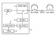
도 1은 일반적인 OTDR 내부구성과 이를 이용한 광섬유 손실측정계를 나타내는 블록도이다.1 is a block diagram illustrating a general OTDR internal configuration and an optical fiber loss measuring system using the same.
광원(4)에서 얻어진 광전력을 측정하고자 하는 광섬유(10, 11)에 입사시키면 광섬유 내에서 발생한 후방산란광은 반사점까지의 거리에 비례한 시간 후에 입사단으로 되돌아온다.When the optical power obtained from the
OTDR(1)은 되돌아 온 광을 방향광커플러(5)로 분리하여 광검출기(6)에 의해 광을 검출하고 전기신호로 변환한 후, 신호처리기(7)를 거쳐 오실로스코프(8)로 파형을 관측하고, 이를 기록계(9)를 통해 기록한다.The OTDR 1 separates the returned light into the directional optocoupler 5, detects the light by the
후방산란광은 출사단쪽으로 진행하는 광전력의 세기에 비례하게 되며, 이러한 후방산란광을 이용하여 광섬유의 접속손실, 파단점, 광섬유의 길이 등을 측정할 수 있다.The backscattered light is proportional to the intensity of the optical power propagated toward the exit end, and the backscattered light can measure the connection loss, break point, and the length of the fiber.
도 2는 일반적인 광소스와 광파워미터를 이용한 반사율 측정장치의 블록도이다.2 is a block diagram of a reflectance measuring apparatus using a general light source and an optical power meter.
광섬유 반사체(22)의 여러 파장에 대한 반사율을 측정하기 위해서는 일반적 으로 50:50 커플러(21)의 출력포트에 광섬유 반사체(22)를 접속시켜 측정장치를 구성한다. 파장을 가변할 수 있는 레이저를 광소스(23)로 사용하여 커플러(21)의 입력포트 중 하나에 입사시키고, 커플러(21)의 나머지 입력포트에는 광파워미터(power meter)(24)를 연결하여 광섬유 반사체(22)로부터 반사되어 나오는 신호광을 검출한다.In order to measure reflectance of various wavelengths of the
이와 같은 광소스, 광파워미터 또는 OTDR 장비는 이동 통신망의 운용 중에 광섬유의 장애가 발생하였을 때에 장애 측정을 위해 널리 사용되고 있다.Such an optical source, an optical power meter, or an OTDR device is widely used for failure measurement when a failure of an optical fiber occurs during operation of a mobile communication network.
그런데, 광소스와 광파워미터를 일체로 구비한 측정장치는 보급되어 있으나 OTDR 장비까지 일체로 구비한 측정장치는 개발되지 않았다. 따라 광섬유에 장애가 발생하여 현장에 긴급 출동할 때에는 광소스, 광파워미터 또는 OTDR 장비를 각각 휴대하여야만 한다. 설사 광소스와 광파워미터 및 OTDR 장비를 일체로 구비한 측정장치가 개발된 실정이라 가정하더라도 장애 발생으로 인해 현장에 긴급 출동할 때에는 해당 측정장치를 휴대하여야만 하는 번거로운 문제점이 있었다.By the way, a measuring device having an integrated light source and an optical power meter is widely used, but a measuring device having an integrated OTDR device has not been developed. As a result, when an optical fiber fails and is dispatched to the site, the light source, optical power meter or OTDR equipment must be carried separately. Even if it is assumed that a measuring device having a light source, an optical power meter, and an OTDR device has been developed, there is a problem in that the measuring device must be carried when an emergency dispatch occurs due to a failure.
본 발명은 이와 같은 종래의 문제점을 해결하기 위하여 제안한 것으로, 현대사회에서 생활 필수품화 된 이동 통신 단말기에 OTDR 기능을 추가하여 광섬유의 장애 측정 시에 휴대 중인 이동 통신 단말기를 활용하여 광섬유의 손실을 측정할 수 있도록 하는 데 그 목적이 있다.The present invention has been proposed to solve such a conventional problem, by adding the OTDR function to the mobile communication terminal has become a necessity in the modern society to measure the loss of the optical fiber by using a mobile communication terminal in the measurement of the failure of the optical fiber The purpose is to make it possible.
본 발명의 다른 목적은 이동 통신 단말기에 광소스와 광파워미터 기능을 추가하여 광섬유의 장애 측정 시에 휴대 중인 이동 통신 단말기를 활용하여 광섬유의 반사율을 측정할 수 있도록 하는 데 있다.Another object of the present invention is to add an optical source and an optical power meter function to the mobile communication terminal so that the reflectance of the optical fiber can be measured by using the mobile communication terminal that is being carried when the failure of the optical fiber.
이와 같은 목적들을 실현하기 위한 본 발명의 제 1 관점에 따른 광섬유 장애 측정을 위한 이동 통신 단말기는, 이동 통신 시스템으로부터 이동 통신 서비스를 제공받는 이동 통신 단말기로서, 광섬유의 손실 측정을 위한 레이저를 제공하는 광소스와, 광소스에서 얻어진 광전력을 측정하고자 하는 광섬유에 입사시킨 후 광섬유 내에서 발생한 후방산란광을 검출하여 광섬유의 손실을 측정하는 OTDR과, OTDR에 의한 손실 측정을 제어하거나 그 측정값을 이동 통신 시스템으로 전송하기 위한 프로그램을 저장하는 장애 관리 프로그램 저장부와, 장애 관리 프로그램 저장부에 저장된 프로그램에 의해 OTDR에 의한 광섬유의 손실 측정을 제어하면서 측정값을 이동 통신 시스템을 통해 전송하는 제어부를 포함한다.A mobile communication terminal for measuring a fiber failure according to a first aspect of the present invention for realizing the above objects is a mobile communication terminal that receives a mobile communication service from a mobile communication system, and provides a laser for measuring loss of an optical fiber. OTDR which measures the loss of the optical fiber by detecting the back scattered light generated in the optical fiber after entering the optical source and the optical power to measure the optical power obtained from the optical source, and control or move the measured value of the loss measurement by the OTDR A fault management program storage unit for storing a program for transmission to the communication system, and a control unit for transmitting the measurement value through the mobile communication system while controlling the loss measurement of the optical fiber by the OTDR by a program stored in the fault management program storage unit do.
본 발명의 제 2 관점에 따른 광섬유 장애 측정을 위한 이동 통신 단말기는, 이동 통신 시스템으로부터 이동 통신 서비스를 제공받는 이동 통신 단말기로서, 광섬유의 반사율 측정을 위한 레이저를 제공하는 광소스와, 광소스에 의한 레이저가 광섬유에 입사된 후 광섬유 반사체로부터 반사되어 나오는 신호광을 검출하여 여러 파장에 대한 반사율을 측정하는 광파워미터와, 광파워미터에 의한 반사율 측정을 제어하거나 그 측정값을 이동 통신 시스템으로 전송하기 위한 프로그램을 저장하는 장애 관리 프로그램 저장부와, 장애 관리 프로그램 저장부에 저장된 프로그램에 의해 광파워미터에 의한 광섬유의 반사율 측정을 제어하면서 측정값을 이동 통신 시스템을 통해 전송하는 제어부를 포함한다.A mobile communication terminal for measuring a fiber failure according to a second aspect of the present invention is a mobile communication terminal provided with a mobile communication service from a mobile communication system, comprising: an optical source for providing a laser for measuring a reflectance of an optical fiber; An optical power meter that detects the signal light reflected from the optical fiber reflector after the laser is incident on the optical fiber and measures the reflectance of various wavelengths, and controls the reflectance measurement by the optical power meter or transmits the measured value to the mobile communication system And a control unit for transmitting a measurement value through the mobile communication system while controlling a reflectance measurement of the optical fiber by the optical power meter by a program stored in the failure management program storage unit.
본 발명의 제 3 관점에 따른 광섬유 장애 측정을 위한 이동 통신 시스템은, 광소스, 광파워미터 또는 OTDR를 구비한 이동 통신 단말기와, 이동 통신 단말기에게 이동 통신 서비스를 제공함과 아울러 이동 통신 단말기로부터 측정값을 전송 받는 이동 통신망과, 이동 통신망을 통해 측정값을 전송 받아서 장애 관리 데이터베이스를 구축하는 장애 관리 서버를 포함한다.A mobile communication system for measuring a fiber failure according to a third aspect of the present invention provides a mobile communication terminal provided with an optical source, an optical power meter, or an OTDR, and provides a mobile communication service to the mobile communication terminal, and measures from the mobile communication terminal. It includes a mobile communication network receiving a value, and a failure management server receiving a measurement value through the mobile communication network to build a failure management database.
이하, 본 발명의 바람직한 실시 예를 첨부된 도면들을 참조하여 상세히 설명한다. 아울러, 본 발명을 설명함에 있어 관련된 공지 구성 또는 기능에 대한 구체적인 설명이 본 발명의 요지를 흐릴 수 있다고 판단되는 경우에는 그 상세한 설명을 생략한다.Hereinafter, exemplary embodiments of the present invention will be described in detail with reference to the accompanying drawings. In addition, in describing the present invention, when it is determined that the detailed description of the related well-known configuration or function may obscure the gist of the present invention, the detailed description thereof will be omitted.
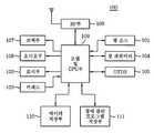
도 3은 본 발명에 따른 광섬유 장애 측정을 위한 이동 통신 단말기의 블록도이다.3 is a block diagram of a mobile communication terminal for measuring a fiber failure according to the present invention.
도시된 바와 같이 본 발명에 의한 이동 통신 단말기(100)는, 광소스(101), 표시부(102), 키패드(103), 광파워미터(104), OTDR(105), RF부(106), 코덱부(107), 오디오부(108), 모뎀 및 CPU부(이하, "제어부"라 함)(109), 데이터 저장부(110), 장애 관리 프로그램 저장부(111) 등을 포함하여 구성된다.As shown, the
광소스(101)는 광섬유의 반사율 측정을 위한 레이저를 파장(850nm, 1300nm, 1310nm, 1490nm, 1550nm, 1625nm)을 가변시켜 제공한다. 또한 OTDR(105)을 위해 광섬유의 손실 측정을 위한 레이저를 제공한다.The
표시부(102)는 제어부(109)로부터 디스플레이 제어신호를 입력받은 후 사용자에게 디스플레이하는 표시창의 역할을 한다.The
키패드(103)는 숫자 버튼, 기호 버튼 및 기타 기능 버튼으로 이루어져 필요한 정보를 통신 단말기에 입력해주기 위해 사용되고 제어부(109)와 신호를 교환하는 역할을 한다.The
광파워미터(104)는 공지의 커플러와 광섬유 반사체 및 광소스(101)와 더불어 반사율 측정장치를 이루며, 광섬유 반사체로부터 반사되어 나오는 신호광을 검출하여 여러 파장에 대한 반사율을 측정한다.The optical power meter 104 forms a reflectance measuring device together with a known coupler, an optical fiber reflector, and a
OTDR(105)은 광소스(101)에서 얻어진 광전력을 측정하고자 하는 광섬유에 입사시킨 후 광섬유 내에서 발생한 후방산란광을 검출하여 광섬유의 접속손실, 파단점, 광섬유의 길이 등을 측정한다.The OTDR 105 detects the backscattered light generated in the optical fiber after injecting the optical power obtained from the
RF부(106)는 안테나를 통해 수신된 무선 신호를 적정 레벨로 조정한 후 제어부(109)로 제공하며, 제어부(109)로부터 송신 요청된 신호를 안테나를 통해 무선 신호로 송출하는 역할을 한다.The
제어부(109)는 RF부(106)로부터 제공받은 신호를 입력받아 캐리어에 실린 오디오 데이터 및 각종 정보 데이터 등을 복조하고, 오디오부(108) 및 키패드(103)를 통한 입력 신호를 캐리어에 실어 변조하여 RF부(106)를 통해 송출한다.The
코덱부(107)는 제어부(109)에서 출력한 디지털 오디오 신호를 입력받아 아날로그 신호로 변환한 후 오디오부(108)로 출력하는 역할을 한다.The
오디오부(108)는 코덱부(107)에서 출력한 아날로그 오디오 신호를 증폭하여 사용자가 들을 수 있는 기계적 신호로 변환하여 출력하며, 외부로부터 입력되는 음성 및 음향을 전기적 신호로 변환하여 제어부(109)로 제공하는 역할을 한다.The audio unit 108 amplifies the analog audio signal output from the
데이터 저장부(110)는 광파워미터(104) 및 OTDR(105)에 의해 측정된 반사율, 접속손실, 파단점, 광섬유의 길이 등의 측정값을 저장한다.The
장애 관리 프로그램 저장부(111)는 광섬유의 장애를 측정하기 위한 광소스(101), 광파워미터(104) 및 OTDR(105)의 운용과 그 측정값을 이동통신망을 통해 전송하기 위한 프로그램을 저장한다.The failure management
한편, 도 3의 실시 예에서는 광소스(101), 광파워미터(104) 및 OTDR(105)이 모두 이동 통신 단말기(100)로 일체로 구비된 경우를 예로서 설명하였으나, 이 중에서 하나만 택일적으로 구비될 수도 있다. 하지만 광소스(101)와 광파워미터(104)는 함께 채용되는 것이 바람직하며, OTDR(105)만이 일체로 구비된 경우라면 OTDR(105) 내에 광소스가 별도로 구비된다.Meanwhile, in the embodiment of FIG. 3, the
도 4는 본 발명에 따른 광섬유 장애 측정 시스템의 블록도이다.4 is a block diagram of an optical fiber failure measuring system according to the present invention.
이에 나타낸 바와 같이 본 발명의 장애 측정 시스템은, 이동 통신 단말기(MS: Mobile Station)(100), 기지국(BTS: Base Transceiver Station)(201), 기지국 제어기(BSC: Base Station Controller)(202), 기지국 관리기(BSM: Base Station Management)(203), 이동 교환국(MSC: Mobile Switching Center)/방문자 위치 등록기(VLR: Visitor Location Register)(204), 홈 위치 등록기(HLR: Home Location Register)(205), 장애 관리 서버(Fault Management Server)(301), 장애 관리 데이터베이스(302) 등을 포함하여 구성된다.As described above, the fault measurement system of the present invention includes a mobile station (MS) 100, a base transceiver station (BTS) 201, a base station controller (BSC) 202, Base Station Management (BSM) (203), Mobile Switching Center (MSC) / Visitor Location Register (VLR) (204), Home Location Register (HLR) (205) , A
이동 통신 단말기(100)는 도 3의 블록도에 나타낸 바와 같이 광소스(101), 광파워미터(104) 또는 OTDR(105)를 구비한다.The
기지국(201), 기지국 제어기(202), 기지국 관리기(203), 이동 교환국/방문자 위치 등록기(204) 및 홈 위치 등록기(205)는 공지의 이동 통신 시스템으로서, 이동 통신 단말기(100)와 장애 관리 서버(301) 사이의 신호 전달 경로를 제공한다.The
장애 관리 서버(301)는 이동 통신 단말기(100)로부터 이동 통신망을 통해 장애 측정 데이터를 전달받아서 장애 관리 데이터베이스(302)를 구축한다.The
지금까지 설명한 바와 같은 본 발명에 따른 광섬유 장애 측정을 위한 이동 통신 단말기 및 시스템의 동작 과정을 도 1 내지 도 4를 참조하여 살펴보기로 한다. 여기서 이동 통신 시스템에 의한 데이터 전송 과정 등은 공지의 기술 사상에 해당하므로 그 상세한 설명은 생략한다.An operation process of a mobile communication terminal and a system for measuring a fiber failure according to the present invention as described above will be described with reference to FIGS. 1 to 4. Here, the data transmission process by the mobile communication system corresponds to a known technical idea, and thus a detailed description thereof will be omitted.
먼저, 이동 통신 단말기(100)를 이용하여 광섬유의 손실을 측정하고자 할 때에는 도 1에서와 같이 이동 통신 단말기(100)의 OTDR(105)를 측정하고자 하는 광섬유(10, 11)에 연결하며, 키패드(103)를 조작하여 광섬유 손실 측정 기능을 선택한다.First, when the loss of the optical fiber is to be measured using the
그러면, 제어부(109)는 장애 관리 프로그램 저장부(111)에 저장되어 있는 장애 관리 프로그램을 구동하며, 이 구동 프로그램에 의해 광섬유 손실 측정 과정이 수행된다.Then, the
광소스(101)에서 얻어진 광전력을 측정하고자 하는 광섬유(10, 11)에 입사시키면 광섬유 내에서 발생한 후방산란광은 반사점까지의 거리에 비례한 시간 후에 입사단으로 되돌아온다.When the light power obtained from the
OTDR(105)은 되돌아 온 광을 방향광커플러로 분리하여 광검출기에 의해 광을 검출하고 전기신호로 변환한 후, 신호처리기를 거쳐 오실로스코프로 파형을 관측하고, 이를 기록계를 통해 기록한다.The
후방산란광은 출사단쪽으로 진행하는 광전력의 세기에 비례하게 되며, 이러한 후방산란광을 이용하여 광섬유의 접속손실, 파단점, 광섬유의 길이 등을 측정할 수 있다.The backscattered light is proportional to the intensity of the optical power propagated toward the exit end, and the backscattered light can measure the connection loss, break point, and the length of the fiber.
이때, OTDR(105)에 의해 측정된 데이터는 데이터 저장부(110)에 저장됨과 아울러 이동 통신망을 통해 장애 관리 서버(301)로 전송된다.In this case, the data measured by the
장애 관리 서버(301)는 이동 통신 단말기(100)로부터 이동 통신망을 통해 장애 측정 데이터를 전달받아서 장애 관리 데이터베이스(302)를 구축하며, 운용자는 장애 관리 데이터베이스(302)를 통해 광섬유의 손실을 포함한 각종 장애 관리 정보를 확인할 수 있다.The
다음으로, 이동 통신 단말기(100)를 이용하여 광섬유의 반사율을 측정하고자 할 때에는 도 2에서와 같이 커플러의 출력포트에 광섬유 반사체를 접속시키고, 파장을 가변할 수 있는 레이저를 광소스(101)로 사용하여 커플러의 입력포트 중 하나에 입사시키며, 커플러의 나머지 입력포트에는 광파워미터(104)를 연결한다.Next, when the reflectance of the optical fiber is to be measured using the
그리고, 키패드(103)를 조작하여 광섬유 반사율 측정 기능을 선택하면 제어부(109)는 장애 관리 프로그램 저장부(111)에 저장되어 있는 장애 관리 프로그램을 구동하며, 이 구동 프로그램에 의해 광섬유 반사율 측정 과정이 수행된다.When the optical fiber reflectance measurement function is selected by operating the
광파워미터(104)는 광섬유 반사체로부터 반사되어 나오는 신호광을 검출하며, 광파워미터(104)에 의해 측정된 데이터는 데이터 저장부(110)에 저장됨과 아울 러 이동 통신망을 통해 장애 관리 서버(301)로 전송된다.The optical power meter 104 detects the signal light reflected from the optical fiber reflector, and the data measured by the optical power meter 104 is stored in the
장애 관리 서버(301)는 이동 통신 단말기(100)로부터 이동 통신망을 통해 장애 측정 데이터를 전달받아서 장애 관리 데이터베이스(302)를 구축하며, 운용자는 장애 관리 데이터베이스(302)를 통해 광섬유의 반사율을 포함한 각종 장애 관리 정보를 확인할 수 있다.The
지금까지는 본 발명의 일 실시 예에 국한하여 설명하였으나 본 발명의 기술이 당업자에 의하여 용이하게 변형 실시될 가능성이 자명하다. 이러한 변형된 실시 예들은 본 발명의 특허청구범위에 기재된 기술사상에 당연히 포함되는 것으로 해석되어야 할 것이다.It has been described so far limited to one embodiment of the present invention, it is obvious that the technology of the present invention can be easily modified by those skilled in the art. Such modified embodiments should be construed as naturally included in the technical spirit described in the claims of the present invention.
전술한 바와 같이 본 발명은 현대사회에서 생활 필수품화 된 이동 통신 단말기에 OTDR 기능을 추가하여 광섬유의 장애 측정 시에 휴대 중인 이동 통신 단말기를 활용하여 광섬유의 손실을 측정할 수 있으며, 이동 통신 단말기에 광소스와 광파워미터 기능을 추가하여 광섬유의 장애 측정 시에도 휴대 중인 이동 통신 단말기를 활용하여 광섬유의 반사율을 측정할 수 있는 편의성을 제공하는 효과가 있다.As described above, the present invention adds an OTDR function to a mobile communication terminal, which is a necessity in modern society, so that the loss of the optical fiber can be measured by using a mobile communication terminal that is portable when measuring a failure of the optical fiber. By adding an optical source and an optical power meter function, there is an effect of providing convenience for measuring the reflectance of the optical fiber by using a mobile communication terminal which is carried even when measuring the failure of the optical fiber.
Claims (3)
Translated fromKoreanPriority Applications (1)
| Application Number | Priority Date | Filing Date | Title |
|---|---|---|---|
| KR1020060045613AKR101235174B1 (en) | 2006-05-22 | 2006-05-22 | Mobile communication terminal for fault measurement of optical cable |
Applications Claiming Priority (1)
| Application Number | Priority Date | Filing Date | Title |
|---|---|---|---|
| KR1020060045613AKR101235174B1 (en) | 2006-05-22 | 2006-05-22 | Mobile communication terminal for fault measurement of optical cable |
Publications (2)
| Publication Number | Publication Date |
|---|---|
| KR20070112562Atrue KR20070112562A (en) | 2007-11-27 |
| KR101235174B1 KR101235174B1 (en) | 2013-02-20 |
Family
ID=39090833
Family Applications (1)
| Application Number | Title | Priority Date | Filing Date |
|---|---|---|---|
| KR1020060045613AExpired - Fee RelatedKR101235174B1 (en) | 2006-05-22 | 2006-05-22 | Mobile communication terminal for fault measurement of optical cable |
Country Status (1)
| Country | Link |
|---|---|
| KR (1) | KR101235174B1 (en) |
Cited By (5)
| Publication number | Priority date | Publication date | Assignee | Title |
|---|---|---|---|---|
| KR101226549B1 (en)* | 2011-08-16 | 2013-02-06 | 성창통신 주식회사 | Optical cable fiber identifier |
| CN102946272A (en)* | 2012-11-21 | 2013-02-27 | 博创科技股份有限公司 | Separated type optical testing device based on commonly-used mobile intelligent terminal |
| CN104464449A (en)* | 2014-11-04 | 2015-03-25 | 北京物联世纪科技有限公司 | Optical fiber end connection testing practical training device |
| KR20160135924A (en)* | 2015-05-19 | 2016-11-29 | 한국전자통신연구원 | Handheld measurement device for optical link quality |
| CN112629820A (en)* | 2019-10-08 | 2021-04-09 | 中国移动通信集团浙江有限公司 | Optical fiber matching test system and method |
Family Cites Families (1)
| Publication number | Priority date | Publication date | Assignee | Title |
|---|---|---|---|---|
| JP2000193555A (en)* | 1998-12-25 | 2000-07-14 | Ando Electric Co Ltd | Optical fiber line monitoring system |
- 2006
- 2006-05-22KRKR1020060045613Apatent/KR101235174B1/ennot_activeExpired - Fee Related
Cited By (8)
| Publication number | Priority date | Publication date | Assignee | Title |
|---|---|---|---|---|
| KR101226549B1 (en)* | 2011-08-16 | 2013-02-06 | 성창통신 주식회사 | Optical cable fiber identifier |
| WO2013025001A3 (en)* | 2011-08-16 | 2013-04-11 | 성창통신 주식회사 | Identifier for core wire of optical cable |
| CN102946272A (en)* | 2012-11-21 | 2013-02-27 | 博创科技股份有限公司 | Separated type optical testing device based on commonly-used mobile intelligent terminal |
| CN102946272B (en)* | 2012-11-21 | 2015-07-01 | 博创科技股份有限公司 | Separated type optical testing device based on commonly-used mobile intelligent terminal |
| CN104464449A (en)* | 2014-11-04 | 2015-03-25 | 北京物联世纪科技有限公司 | Optical fiber end connection testing practical training device |
| KR20160135924A (en)* | 2015-05-19 | 2016-11-29 | 한국전자통신연구원 | Handheld measurement device for optical link quality |
| CN112629820A (en)* | 2019-10-08 | 2021-04-09 | 中国移动通信集团浙江有限公司 | Optical fiber matching test system and method |
| CN112629820B (en)* | 2019-10-08 | 2023-09-19 | 中国移动通信集团浙江有限公司 | Optical fiber matching test system and method |
Also Published As
| Publication number | Publication date |
|---|---|
| KR101235174B1 (en) | 2013-02-20 |
Similar Documents
| Publication | Publication Date | Title |
|---|---|---|
| US10432302B1 (en) | Bidirectional optical fiber auto-notifier test system | |
| CN102265533B (en) | Adopt the unidirectional absolute light attenuation measurement of OTDR | |
| EP1881623B1 (en) | Optical transmission line monitoring device, optical transmission line monitioring method and computer program | |
| US11860058B2 (en) | Fiber-optic testing source and fiber-optic testing receiver for multi-fiber cable testing | |
| CN105530046B (en) | Realize the method and system that luminous power and branch off attenuation failure are tested automatically | |
| CN111595241B (en) | Optical fiber monitoring method and device | |
| JP4902213B2 (en) | Optical line monitoring apparatus and method | |
| CN103647601A (en) | Fiber monitoring system | |
| KR101235174B1 (en) | Mobile communication terminal for fault measurement of optical cable | |
| CN107332101A (en) | It is a kind of can Dynamic Execution optical time domain reflection detection component and detection method | |
| KR20180098718A (en) | Optical time domain reflectometer for divided optical fiber monitering on optical termination box | |
| US12061131B2 (en) | Judgment device and judgment method | |
| JP2002520602A (en) | Method and system for performing control and monitoring measurements in an optical transmission path | |
| JP5467080B2 (en) | Optical fiber core determination device and determination method thereof | |
| CN203675113U (en) | Optical fiber monitoring system | |
| CN201118599Y (en) | A kind of optical module equipment and motherboard | |
| JP2006071602A (en) | Optical path abnormality diagnostic device and diagnostic method | |
| KR101210465B1 (en) | One body type optical power meter having fault position finder | |
| US20120163804A1 (en) | Apparatus and method for efficient optical loss measurement | |
| CN217546052U (en) | System combining optical time domain reflectometer and optical fiber vibration sensor | |
| JP2002094457A (en) | System and method for determining wavelength dependent information in an optical communication system | |
| KR20220170530A (en) | Optical subscriber equipment capable of wireless transmission | |
| Cen et al. | Advanced fault-monitoring scheme for ring-based long-reach optical access networks | |
| KR20170125461A (en) | Optical time domain reflectometer for divided optical fiber monitering on optical termination box | |
| JP4523382B2 (en) | Multimode fiber transmission system |
Legal Events
| Date | Code | Title | Description |
|---|---|---|---|
| PA0109 | Patent application | St.27 status event code:A-0-1-A10-A12-nap-PA0109 | |
| PG1501 | Laying open of application | St.27 status event code:A-1-1-Q10-Q12-nap-PG1501 | |
| R17-X000 | Change to representative recorded | St.27 status event code:A-3-3-R10-R17-oth-X000 | |
| A201 | Request for examination | ||
| PA0201 | Request for examination | St.27 status event code:A-1-2-D10-D11-exm-PA0201 | |
| D13-X000 | Search requested | St.27 status event code:A-1-2-D10-D13-srh-X000 | |
| D14-X000 | Search report completed | St.27 status event code:A-1-2-D10-D14-srh-X000 | |
| PE0902 | Notice of grounds for rejection | St.27 status event code:A-1-2-D10-D21-exm-PE0902 | |
| E13-X000 | Pre-grant limitation requested | St.27 status event code:A-2-3-E10-E13-lim-X000 | |
| P11-X000 | Amendment of application requested | St.27 status event code:A-2-2-P10-P11-nap-X000 | |
| P13-X000 | Application amended | St.27 status event code:A-2-2-P10-P13-nap-X000 | |
| PN2301 | Change of applicant | St.27 status event code:A-3-3-R10-R13-asn-PN2301 St.27 status event code:A-3-3-R10-R11-asn-PN2301 | |
| E701 | Decision to grant or registration of patent right | ||
| PE0701 | Decision of registration | St.27 status event code:A-1-2-D10-D22-exm-PE0701 | |
| P22-X000 | Classification modified | St.27 status event code:A-2-2-P10-P22-nap-X000 | |
| GRNT | Written decision to grant | ||
| PR0701 | Registration of establishment | St.27 status event code:A-2-4-F10-F11-exm-PR0701 | |
| PR1002 | Payment of registration fee | St.27 status event code:A-2-2-U10-U11-oth-PR1002 Fee payment year number:1 | |
| PG1601 | Publication of registration | St.27 status event code:A-4-4-Q10-Q13-nap-PG1601 | |
| R18-X000 | Changes to party contact information recorded | St.27 status event code:A-5-5-R10-R18-oth-X000 | |
| FPAY | Annual fee payment | Payment date:20160128 Year of fee payment:4 | |
| PR1001 | Payment of annual fee | St.27 status event code:A-4-4-U10-U11-oth-PR1001 Fee payment year number:4 | |
| PR1001 | Payment of annual fee | St.27 status event code:A-4-4-U10-U11-oth-PR1001 Fee payment year number:5 | |
| P22-X000 | Classification modified | St.27 status event code:A-4-4-P10-P22-nap-X000 | |
| LAPS | Lapse due to unpaid annual fee | ||
| PC1903 | Unpaid annual fee | St.27 status event code:A-4-4-U10-U13-oth-PC1903 Not in force date:20180215 Payment event data comment text:Termination Category : DEFAULT_OF_REGISTRATION_FEE | |
| PC1903 | Unpaid annual fee | St.27 status event code:N-4-6-H10-H13-oth-PC1903 Ip right cessation event data comment text:Termination Category : DEFAULT_OF_REGISTRATION_FEE Not in force date:20180215 |