KR20070109384A - Shower Heads in Atomic Layer Deposition Process Equipment - Google Patents
Shower Heads in Atomic Layer Deposition Process EquipmentDownload PDFInfo
- Publication number
- KR20070109384A KR20070109384AKR1020060042261AKR20060042261AKR20070109384AKR 20070109384 AKR20070109384 AKR 20070109384AKR 1020060042261 AKR1020060042261 AKR 1020060042261AKR 20060042261 AKR20060042261 AKR 20060042261AKR 20070109384 AKR20070109384 AKR 20070109384A
- Authority
- KR
- South Korea
- Prior art keywords
- oxidizing gas
- injection hole
- gas
- shower head
- reaction chamber
- Prior art date
- Legal status (The legal status is an assumption and is not a legal conclusion. Google has not performed a legal analysis and makes no representation as to the accuracy of the status listed.)
- Withdrawn
Links
Images


Classifications
- C—CHEMISTRY; METALLURGY
- C07—ORGANIC CHEMISTRY
- C07F—ACYCLIC, CARBOCYCLIC OR HETEROCYCLIC COMPOUNDS CONTAINING ELEMENTS OTHER THAN CARBON, HYDROGEN, HALOGEN, OXYGEN, NITROGEN, SULFUR, SELENIUM OR TELLURIUM
- C07F5/00—Compounds containing elements of Groups 3 or 13 of the Periodic Table
- C07F5/06—Aluminium compounds
- C07F5/061—Aluminium compounds with C-aluminium linkage
- C07F5/062—Al linked exclusively to C
- C—CHEMISTRY; METALLURGY
- C23—COATING METALLIC MATERIAL; COATING MATERIAL WITH METALLIC MATERIAL; CHEMICAL SURFACE TREATMENT; DIFFUSION TREATMENT OF METALLIC MATERIAL; COATING BY VACUUM EVAPORATION, BY SPUTTERING, BY ION IMPLANTATION OR BY CHEMICAL VAPOUR DEPOSITION, IN GENERAL; INHIBITING CORROSION OF METALLIC MATERIAL OR INCRUSTATION IN GENERAL
- C23C—COATING METALLIC MATERIAL; COATING MATERIAL WITH METALLIC MATERIAL; SURFACE TREATMENT OF METALLIC MATERIAL BY DIFFUSION INTO THE SURFACE, BY CHEMICAL CONVERSION OR SUBSTITUTION; COATING BY VACUUM EVAPORATION, BY SPUTTERING, BY ION IMPLANTATION OR BY CHEMICAL VAPOUR DEPOSITION, IN GENERAL
- C23C16/00—Chemical coating by decomposition of gaseous compounds, without leaving reaction products of surface material in the coating, i.e. chemical vapour deposition [CVD] processes
- C23C16/44—Chemical coating by decomposition of gaseous compounds, without leaving reaction products of surface material in the coating, i.e. chemical vapour deposition [CVD] processes characterised by the method of coating
- C23C16/455—Chemical coating by decomposition of gaseous compounds, without leaving reaction products of surface material in the coating, i.e. chemical vapour deposition [CVD] processes characterised by the method of coating characterised by the method used for introducing gases into reaction chamber or for modifying gas flows in reaction chamber
- C23C16/45523—Pulsed gas flow or change of composition over time
- C23C16/45525—Atomic layer deposition [ALD]
- C23C16/45544—Atomic layer deposition [ALD] characterized by the apparatus
- C—CHEMISTRY; METALLURGY
- C23—COATING METALLIC MATERIAL; COATING MATERIAL WITH METALLIC MATERIAL; CHEMICAL SURFACE TREATMENT; DIFFUSION TREATMENT OF METALLIC MATERIAL; COATING BY VACUUM EVAPORATION, BY SPUTTERING, BY ION IMPLANTATION OR BY CHEMICAL VAPOUR DEPOSITION, IN GENERAL; INHIBITING CORROSION OF METALLIC MATERIAL OR INCRUSTATION IN GENERAL
- C23C—COATING METALLIC MATERIAL; COATING MATERIAL WITH METALLIC MATERIAL; SURFACE TREATMENT OF METALLIC MATERIAL BY DIFFUSION INTO THE SURFACE, BY CHEMICAL CONVERSION OR SUBSTITUTION; COATING BY VACUUM EVAPORATION, BY SPUTTERING, BY ION IMPLANTATION OR BY CHEMICAL VAPOUR DEPOSITION, IN GENERAL
- C23C16/00—Chemical coating by decomposition of gaseous compounds, without leaving reaction products of surface material in the coating, i.e. chemical vapour deposition [CVD] processes
- C23C16/44—Chemical coating by decomposition of gaseous compounds, without leaving reaction products of surface material in the coating, i.e. chemical vapour deposition [CVD] processes characterised by the method of coating
- C23C16/455—Chemical coating by decomposition of gaseous compounds, without leaving reaction products of surface material in the coating, i.e. chemical vapour deposition [CVD] processes characterised by the method of coating characterised by the method used for introducing gases into reaction chamber or for modifying gas flows in reaction chamber
- C23C16/45523—Pulsed gas flow or change of composition over time
- C23C16/45525—Atomic layer deposition [ALD]
- C23C16/45553—Atomic layer deposition [ALD] characterized by the use of precursors specially adapted for ALD
- C—CHEMISTRY; METALLURGY
- C23—COATING METALLIC MATERIAL; COATING MATERIAL WITH METALLIC MATERIAL; CHEMICAL SURFACE TREATMENT; DIFFUSION TREATMENT OF METALLIC MATERIAL; COATING BY VACUUM EVAPORATION, BY SPUTTERING, BY ION IMPLANTATION OR BY CHEMICAL VAPOUR DEPOSITION, IN GENERAL; INHIBITING CORROSION OF METALLIC MATERIAL OR INCRUSTATION IN GENERAL
- C23C—COATING METALLIC MATERIAL; COATING MATERIAL WITH METALLIC MATERIAL; SURFACE TREATMENT OF METALLIC MATERIAL BY DIFFUSION INTO THE SURFACE, BY CHEMICAL CONVERSION OR SUBSTITUTION; COATING BY VACUUM EVAPORATION, BY SPUTTERING, BY ION IMPLANTATION OR BY CHEMICAL VAPOUR DEPOSITION, IN GENERAL
- C23C16/00—Chemical coating by decomposition of gaseous compounds, without leaving reaction products of surface material in the coating, i.e. chemical vapour deposition [CVD] processes
- C23C16/44—Chemical coating by decomposition of gaseous compounds, without leaving reaction products of surface material in the coating, i.e. chemical vapour deposition [CVD] processes characterised by the method of coating
- C23C16/455—Chemical coating by decomposition of gaseous compounds, without leaving reaction products of surface material in the coating, i.e. chemical vapour deposition [CVD] processes characterised by the method of coating characterised by the method used for introducing gases into reaction chamber or for modifying gas flows in reaction chamber
- C23C16/45563—Gas nozzles
- C23C16/45565—Shower nozzles
- C—CHEMISTRY; METALLURGY
- C23—COATING METALLIC MATERIAL; COATING MATERIAL WITH METALLIC MATERIAL; CHEMICAL SURFACE TREATMENT; DIFFUSION TREATMENT OF METALLIC MATERIAL; COATING BY VACUUM EVAPORATION, BY SPUTTERING, BY ION IMPLANTATION OR BY CHEMICAL VAPOUR DEPOSITION, IN GENERAL; INHIBITING CORROSION OF METALLIC MATERIAL OR INCRUSTATION IN GENERAL
- C23C—COATING METALLIC MATERIAL; COATING MATERIAL WITH METALLIC MATERIAL; SURFACE TREATMENT OF METALLIC MATERIAL BY DIFFUSION INTO THE SURFACE, BY CHEMICAL CONVERSION OR SUBSTITUTION; COATING BY VACUUM EVAPORATION, BY SPUTTERING, BY ION IMPLANTATION OR BY CHEMICAL VAPOUR DEPOSITION, IN GENERAL
- C23C16/00—Chemical coating by decomposition of gaseous compounds, without leaving reaction products of surface material in the coating, i.e. chemical vapour deposition [CVD] processes
- C23C16/44—Chemical coating by decomposition of gaseous compounds, without leaving reaction products of surface material in the coating, i.e. chemical vapour deposition [CVD] processes characterised by the method of coating
- C23C16/455—Chemical coating by decomposition of gaseous compounds, without leaving reaction products of surface material in the coating, i.e. chemical vapour deposition [CVD] processes characterised by the method of coating characterised by the method used for introducing gases into reaction chamber or for modifying gas flows in reaction chamber
- C23C16/45563—Gas nozzles
- C23C16/45572—Cooled nozzles
- C—CHEMISTRY; METALLURGY
- C23—COATING METALLIC MATERIAL; COATING MATERIAL WITH METALLIC MATERIAL; CHEMICAL SURFACE TREATMENT; DIFFUSION TREATMENT OF METALLIC MATERIAL; COATING BY VACUUM EVAPORATION, BY SPUTTERING, BY ION IMPLANTATION OR BY CHEMICAL VAPOUR DEPOSITION, IN GENERAL; INHIBITING CORROSION OF METALLIC MATERIAL OR INCRUSTATION IN GENERAL
- C23C—COATING METALLIC MATERIAL; COATING MATERIAL WITH METALLIC MATERIAL; SURFACE TREATMENT OF METALLIC MATERIAL BY DIFFUSION INTO THE SURFACE, BY CHEMICAL CONVERSION OR SUBSTITUTION; COATING BY VACUUM EVAPORATION, BY SPUTTERING, BY ION IMPLANTATION OR BY CHEMICAL VAPOUR DEPOSITION, IN GENERAL
- C23C16/00—Chemical coating by decomposition of gaseous compounds, without leaving reaction products of surface material in the coating, i.e. chemical vapour deposition [CVD] processes
- C23C16/44—Chemical coating by decomposition of gaseous compounds, without leaving reaction products of surface material in the coating, i.e. chemical vapour deposition [CVD] processes characterised by the method of coating
- C23C16/455—Chemical coating by decomposition of gaseous compounds, without leaving reaction products of surface material in the coating, i.e. chemical vapour deposition [CVD] processes characterised by the method of coating characterised by the method used for introducing gases into reaction chamber or for modifying gas flows in reaction chamber
- C23C16/45563—Gas nozzles
- C23C16/45574—Nozzles for more than one gas
- H—ELECTRICITY
- H01—ELECTRIC ELEMENTS
- H01L—SEMICONDUCTOR DEVICES NOT COVERED BY CLASS H10
- H01L21/00—Processes or apparatus adapted for the manufacture or treatment of semiconductor or solid state devices or of parts thereof
- H01L21/02—Manufacture or treatment of semiconductor devices or of parts thereof
- H01L21/02104—Forming layers
- H01L21/02107—Forming insulating materials on a substrate
- H01L21/02109—Forming insulating materials on a substrate characterised by the type of layer, e.g. type of material, porous/non-porous, pre-cursors, mixtures or laminates
- H01L21/02112—Forming insulating materials on a substrate characterised by the type of layer, e.g. type of material, porous/non-porous, pre-cursors, mixtures or laminates characterised by the material of the layer
- H01L21/02172—Forming insulating materials on a substrate characterised by the type of layer, e.g. type of material, porous/non-porous, pre-cursors, mixtures or laminates characterised by the material of the layer the material containing at least one metal element, e.g. metal oxides, metal nitrides, metal oxynitrides or metal carbides
- H01L21/02175—Forming insulating materials on a substrate characterised by the type of layer, e.g. type of material, porous/non-porous, pre-cursors, mixtures or laminates characterised by the material of the layer the material containing at least one metal element, e.g. metal oxides, metal nitrides, metal oxynitrides or metal carbides characterised by the metal
- H01L21/02178—Forming insulating materials on a substrate characterised by the type of layer, e.g. type of material, porous/non-porous, pre-cursors, mixtures or laminates characterised by the material of the layer the material containing at least one metal element, e.g. metal oxides, metal nitrides, metal oxynitrides or metal carbides characterised by the metal the material containing aluminium, e.g. Al2O3
- H—ELECTRICITY
- H01—ELECTRIC ELEMENTS
- H01L—SEMICONDUCTOR DEVICES NOT COVERED BY CLASS H10
- H01L21/00—Processes or apparatus adapted for the manufacture or treatment of semiconductor or solid state devices or of parts thereof
- H01L21/02—Manufacture or treatment of semiconductor devices or of parts thereof
- H01L21/02104—Forming layers
- H01L21/02107—Forming insulating materials on a substrate
- H01L21/02225—Forming insulating materials on a substrate characterised by the process for the formation of the insulating layer
- H01L21/0226—Forming insulating materials on a substrate characterised by the process for the formation of the insulating layer formation by a deposition process
- H01L21/02263—Forming insulating materials on a substrate characterised by the process for the formation of the insulating layer formation by a deposition process deposition from the gas or vapour phase
- H01L21/02271—Forming insulating materials on a substrate characterised by the process for the formation of the insulating layer formation by a deposition process deposition from the gas or vapour phase deposition by decomposition or reaction of gaseous or vapour phase compounds, i.e. chemical vapour deposition
- H01L21/0228—Forming insulating materials on a substrate characterised by the process for the formation of the insulating layer formation by a deposition process deposition from the gas or vapour phase deposition by decomposition or reaction of gaseous or vapour phase compounds, i.e. chemical vapour deposition deposition by cyclic CVD, e.g. ALD, ALE, pulsed CVD
Landscapes
- Chemical & Material Sciences (AREA)
- Engineering & Computer Science (AREA)
- Organic Chemistry (AREA)
- Chemical Kinetics & Catalysis (AREA)
- Mechanical Engineering (AREA)
- General Chemical & Material Sciences (AREA)
- Materials Engineering (AREA)
- Metallurgy (AREA)
- Computer Hardware Design (AREA)
- Microelectronics & Electronic Packaging (AREA)
- Power Engineering (AREA)
- Manufacturing & Machinery (AREA)
- General Physics & Mathematics (AREA)
- Physics & Mathematics (AREA)
- Condensed Matter Physics & Semiconductors (AREA)
- Chemical Vapour Deposition (AREA)
Abstract
Translated fromKoreanDescription
Translated fromKorean도 1은 종래의 원자층 증착 공정 장비의 일례를 보인 단면도.1 is a cross-sectional view showing an example of a conventional atomic layer deposition process equipment.
도 2는 도 1에서의 샤워 헤드를 보다 상세히 보인 단면도.2 is a cross-sectional view of the shower head in FIG. 1 in more detail.
도 3은 도 1에서의 샤워 헤드의 투시도.3 is a perspective view of the shower head in FIG.
도 4는 본 발명의 일 실시예에 따른 원자층 증착 공정 장비에서의 샤워 헤드의 단면도.4 is a cross-sectional view of the shower head in the atomic layer deposition process equipment according to an embodiment of the present invention.
도 5는 도 4의 샤워 헤드의 투시도.5 is a perspective view of the shower head of FIG. 4.
<도면의 주요부분에 대한 부호의 설명><Description of the symbols for the main parts of the drawings>
100 : 샤워 헤드110 : 산화 가스 쿨링 블록100: shower head 110: oxidizing gas cooling block
120 : 버퍼링 블록130 : 소스 가스 쿨링 블록120: buffering block 130: source gas cooling block
142: 산화 가스 분사공152 : 소스 가스 분사공142: oxidizing gas injection hole 152: source gas injection hole
122: 제1 분사공132 : 제2 분사공122: first injection hole 132: second injection hole
본 발명은 반도체 소자 제조 설비용 샤워 헤드(shower head)에 관한 것으로서, 보다 상세하게는 원자층 증착 공정 장비에서의 산화 가스의 환원 방지용 샤워 헤드에 관한 것이다.BACKGROUND OF THE INVENTION 1. Field of the Invention The present invention relates to a shower head for a semiconductor device manufacturing facility, and more particularly, to a shower head for preventing reduction of oxidizing gas in an atomic layer deposition process equipment.
현재의 반도체 소자에 관한 연구는 고집적, 고성능 및 저소비전력을 추구하는 방향으로 진행되고 있다. 그 중 특허 반도체 소자의 고집적화 및 고성능화를 달성하기 위해서는 웨이퍼 상에 박막을 정확하게 형성하는 박막 증착 기술이 무엇보다도 중요하다.Current researches on semiconductor devices are progressing toward high integration, high performance, and low power consumption. Among them, in order to achieve high integration and high performance of a patented semiconductor device, a thin film deposition technology for accurately forming a thin film on a wafer is of paramount importance.
일반적으로 웨이퍼 상에 박막을 형성하는 기술은 크게 물리적 방식을 이용하는 물리 기상 증착(Physical Vapor Deposition; PVD) 방식과 화학적 방식을 이용한 화학 기상 증착(Chemical Vapor Deposition; CVD) 방식으로 분류되어져 왔다. 하지만 반도체 소자가 고집적화 및 고성능화되면서 PVD 및 CVD 방식은 그 한계에 이르게 되었다. 이와 같은 PVD 및 CVD 방식의 한계를 개선하기 위하여 원자층 증착 공정(Atomic Layer Deposition; ALD) 기술이 개발되었다.In general, a technique for forming a thin film on a wafer has been classified into a physical vapor deposition (PVD) method using a physical method and a chemical vapor deposition (CVD) method using a chemical method. However, as semiconductor devices become more integrated and higher performance, PVD and CVD methods have reached their limits. Atomic layer deposition (ALD) technology has been developed to improve the limitations of such PVD and CVD methods.
ALD 기술은 웨이퍼 상에 박막 형성에 필요한 원소를 포함하는 반응 가스들을 순차적으로 공급함으로써 웨이퍼 상에 증착되는 막의 두께를 원자막 단위로 조절한다. 그리고, ALD 기술은 자기 제한적 반응(self-limiting reaction)에 의해 반응 가스가 웨이퍼 표면에서만 반응하고 가스와 가스간의 반응은 일어나지 않는 특징을 갖는다. 그러한 표면 반응 메카니즘에 따라 ALD 기술은 웨이퍼 상에 단일 층을 반 복적으로 증착하여 박막의 두께를 원자막 단위로 제어한다. 그리하여, ALD 기술은 기상 반응을 억제하고 표면 반응에 의존하기 때문에 박막의 특성 향상과 더불어 깊은 컨택 홀(contact hole)에서도 거의 완벽한 단차 피복 결과를 얻을 수 있다.ALD technology controls the thickness of the film deposited on a wafer in atomic units by sequentially supplying reaction gases including elements necessary for thin film formation on the wafer. In addition, ALD technology is characterized by the reaction gas reacts only on the wafer surface by a self-limiting reaction, and the reaction between the gas and the gas does not occur. In response to such surface reaction mechanisms, ALD technology repeatedly deposits a single layer on a wafer to control the thickness of the thin film in atomic layers. Thus, because ALD technology suppresses gas phase reactions and relies on surface reactions, it is possible to improve the properties of thin films and achieve near perfect step coverage even in deep contact holes.
CVD 기술과 ALD 기술을 비교해 보면, CVD에서는 공정 온도와 반응 가스의 흐름에 의하여 박막의 구조나 성질이 크게 변하지만, ALD 공정에서는 상기와 같은 변화 요인이 민감하게 작용하지 않는다. 이러한 이유로 ALD 기술은 넓은 면적의 웨이퍼에 있어서 매우 균일한 두께와 조성을 갖는 박막을 형성할 수 있다.Comparing the CVD technique and the ALD technique, in CVD, the structure and the properties of the thin film are greatly changed by the process temperature and the flow of the reactant gas, but in the ALD process, the above factors of change are not sensitive. For this reason, ALD technology can form thin films with very uniform thickness and composition for large area wafers.
ALD 기술의 원리는 제1 반응 가스의 분자 결합을 파괴하여 제1 반응물을 생성하고, 상기 제1 반응물을 웨이퍼 상에 흡착시킨다. 이후, 잔여 제1 반응물을 외부로 배출하고 제2 반응 가스의 분자 결합을 파괴하여 제2 반응물을 생성한다. 제2 반응물을 웨이퍼 상에 흡착시킨 후, 잔여 제2 반응물을 외부로 배출한다. 제1 반응물 및 제2 반응물을 순차적으로 공급함으로써 웨이퍼 상에 소정의 막을 형성한다. ALD 기술로 소정의 막을 증착하기 위해서 오존 가스(ozone; O3)가 많이 사용된다.The principle of ALD technology breaks the molecular bonds of the first reactant gas to produce a first reactant and adsorb the first reactant onto the wafer. Thereafter, the remaining first reactant is discharged to the outside and the molecular bonds of the second reactant gas are broken to produce a second reactant. After adsorbing the second reactant onto the wafer, the remaining second reactant is discharged to the outside. A predetermined film is formed on the wafer by sequentially supplying the first reactant and the second reactant. Ozone (O3) is often used to deposit certain films by ALD technology.
예를 들면, 산화 알루미늄(aluminum oxide; Al2O3) 막 또는 산화 하프늄(Hf)2) 막은 오존 가스를 이용하여 형성된다. TMA(Tri Methyl Aluminum) 가스와 오존 가스를 웨이퍼 상에 순차적으로 흡착하면 알루미늄 옥사이드막이 형성되고, TEMAH(Tetrakis Ethyl MethyAmino Hafnium) 가스와 오존 가스를 웨이퍼 상에 순차적으로 흡착하면 하프늄 옥사이드막이 형성된다. 오존 가스를 이용하기 위해서는 ALD 장치와 오존 발생 장치를 연결하는 오존 공급라인이 필요하다. 이하에서는 도 1을 참조하여 종래의 원자층 증착 공정 장비에서의 샤워 헤드를 설명한다.For example, an aluminum oxide (Al 2 O 3) film or a hafnium oxide (Hf) 2) film is formed using ozone gas. Adsorption of TMA (Tri Methyl Aluminum) gas and ozone gas on the wafer sequentially forms an aluminum oxide film, and sequential adsorption of TEMAH (Tetrakis Ethyl MethyAmino Hafnium) gas and ozone gas onto the wafer forms a hafnium oxide film. In order to use ozone gas, an ozone supply line connecting an ALD device and an ozone generating device is required. Hereinafter, a shower head in a conventional atomic layer deposition process equipment will be described with reference to FIG. 1.
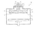
도 1은 종래의 원자층 증착 공정 장비의 일례를 보인 단면도이다.1 is a cross-sectional view showing an example of a conventional atomic layer deposition process equipment.
도 1을 참조하면, 종래의 원자층 증착 공정 장비(10)는 반응 챔버(20), 척(30), 샤워 헤드(40), 산화 가스 공급 라인(50), 소스 가스 공급 라인(60) 등을 구비한다.Referring to FIG. 1, the conventional atomic layer
반응 챔버(20) 내부에는 웨이퍼(W)에 대한 원자층 증착 공정을 수행하기 위한 공간이 있고, 상기 공간에는 웨이퍼(W)를 지지하기 위한 척(30)이 구비된다. 반응 챔버(20)의 하부에는 배출구가 형성되어져 있고, 상기 배출구는 배출 라인과 연통된다. 그리고, 척(30)의 상부에는 웨이퍼(W)가 안착되며, 척(30)에는 히팅 플레이트(heating plate)가 구비된다.In the
반응 챔버(20)의 상부에는 척(30)에 대향되는 방향으로 샤워 헤드(40)가 배치된다. 샤워 헤드(40)에는 산화 가스 공급 라인(50) 및 소스 가스 공급 라인(60)이 연결된다. 이 경우, 소스 가스 공급 라인(60) 및 산화 가스 공급 라인(50)은 원자층 증착 공정 전에 두 가스들이 서로 반응하는 것을 방지하기 위해 샤워 헤드(40)에 각각 독립적으로 연결되어져 있다.The
도 2는 도 1에서의 샤워 헤드(40)를 보다 상세히 보인 단면도이고, 도 3은 도 1에서의 샤워 헤드(40)의 투시도이다.2 is a cross-sectional view of the
도 2 및 도 3을 참조하면, 샤워 헤드(40)의 일면에는 다수의 가스 분사공들(41, 42)이 형성되어, 이는 소스 가스 공급 라인(60) 및 산화 가스 공급 라인(50)에 연통되어져 있다. 그리하여, 소스 가스 공급라인(60) 또는 산화 가스 공급 라인(50)을 통해 제공된 가스들이 분사공들(41, 42)을 통과하여 반응 챔버(20) 의 내부로 분사된다. 샤워 헤드(40)로부터 분사된 가스들은 반응 챔버(20)에 다운 스트림(down stream) 방식으로 공급되어 척(30)에 배치된 웨이퍼(W) 상면에 균일하게 공급된다.2 and 3, a plurality of
상술한 바와 같이, 반도체 소자 제조 과정에서 박막을 형성하는 방법으로 사용되는 원자층 증착 방식에서는 산화알루미늄이라는 유전물질을 생성하게 된다. 그리고, 산화알루미늄이라는 유전물질을 생성하기 위해서는 TMA라는 알루미늄 성분의 케미컬 소스(chemical source)와 산화 가스인 오존 가스가 사용된다. TMA와 오존 가스가 웨이퍼에 균일하게 분사되도록 하기 위해, 도 2 및 도 3에 상세히 도시된 샤워 헤드라는 가스 공급 블록(gas feeding block)을 사용한다. 그리고, 샤워 헤드의 내부에는 각각의 가스 라인이 구비된다.As described above, in the atomic layer deposition method used as a method of forming a thin film in a semiconductor device manufacturing process, a dielectric material called aluminum oxide is generated. In order to generate a dielectric material called aluminum oxide, a chemical source of aluminum, called TMA, and ozone gas, which is an oxidizing gas, is used. In order to uniformly inject the TMA and ozone gas onto the wafer, a gas feeding block called a shower head shown in detail in FIGS. 2 and 3 is used. Each gas line is provided in the shower head.
그러나, 종래의 원자층 증착 공정 장비에서의 샤워 헤드는 열 에너지에 매우 취약한 구조로 형성되어 있다. 즉, 공정 진행 중 산화 가스인 오존 가스의 공급 라인이 히팅 플레이트와 가깝게 된다. 예를 들면, 공정 진행 중 히팅 플레이트는 약 600℃ 까지 가열되는데, 이로 인해 샤워 헤드가 약 200℃ 이상까지 올라가게 된다. 산화 가스인 오존 가스는 반응 챔버에서의 열원(heater)로부터 최대한 멀리 떨어지도록 설계되어지는 것이 바람직한데, 이는 산화 물질인 오존 가스가 열에너지를 받으면 매우 쉽게 환원하는 현상이 일어나기 때문에, 그와 같은 산화물질의 환원 현상을 방지하기 위함이다.However, the shower head in the conventional atomic layer deposition process equipment is formed of a structure that is very vulnerable to thermal energy. That is, the supply line of the ozone gas which is the oxidizing gas during the process is close to the heating plate. For example, the heating plate is heated to about 600 ° C. during the process, which causes the shower head to rise to about 200 ° C. or more. The ozone gas, which is an oxidizing gas, is preferably designed to be as far away from the heat source as possible in the reaction chamber, since it is very easy to reduce the oxidizing substance, ozone gas, when it receives thermal energy. This is to prevent the reduction phenomenon.
이와 같은 산화 물질의 환원 현상으로 인해 공정 불량이 발생하게 되고, 수율을 저하시키게 되는 문제를 야기하게 된다.Due to the reduction phenomenon of the oxidized material, a process defect occurs, which causes a problem of lowering the yield.
따라서, 산화 물질의 환원 현상을 줄여 산화 알루미늄의 생성이 저하되지 않도록 하는 구조를 갖는 샤워 헤드가 절실히 요구된다.Therefore, there is an urgent need for a shower head having a structure that reduces the reduction phenomenon of the oxidizing material so that the production of aluminum oxide is not lowered.
따라서, 본 발명의 목적은 종래의 원자층 증착 공정 장비에서의 샤워 헤드가 갖는 열 에너지에의 취약한 구조 문제를 개선하기 위한 원자층 증착 공정 장비에서의 샤워 헤드를 제공함에 있다.Accordingly, it is an object of the present invention to provide a shower head in an atomic layer deposition process equipment for improving the fragile structural problem of the thermal energy of the shower head in conventional atomic layer deposition process equipment.
본 발명의 다른 목적은 종래의 원자층 증착 공정 장비에서의 샤워 헤드가 공정 진행 중에 히팅 플레이트의 영향으로 인해 온도가 상승하게 되어 산화 가스가 환원되는 현상이 발생되는 문제점을 개선하기 위한 원자층 증착 공정 장비에서의 샤워 헤드를 제공함에 있다.Another object of the present invention is an atomic layer deposition process for improving the problem that the temperature of the shower head in the conventional atomic layer deposition process equipment due to the influence of the heating plate during the process to reduce the oxidizing gas occurs Providing a shower head in the equipment.
본 발명의 또 다른 목적은 공정 불량을 감소시켜 수율을 증가시킬 수 있는 원자층 증착 공정 장비에서의 샤워 헤드를 제공함에 있다.It is yet another object of the present invention to provide a shower head in an atomic layer deposition process equipment which can increase process yield by reducing process defects.
상기의 목적들을 달성하기 위한 본 발명의 일 양상에 따른 원자층 증착 공정 장비에서의 샤워 헤드는, 산화 가스가 상기 장비의 반응 챔버 내부로 주입되도록 하는 경로를 제공하는 산화 가스 분사공이 형성되고, 산화 가스 공급 라인에 연결된 산화 가스 쿨링 블록; 상기 산화 가스 쿨링 블록이 상기 반응 챔버 내의 히팅 플레이트로부터의 열에 의해 가열되는 현상을 줄이기 위해, 상기 산화 가스 분사공과 연통되는 제1 분사공을 구비하며 상기 산화 가스 쿨링 블록의 하부에 배치되는 버퍼링 블록; 및 소스 가스가 상기 반응 챔버의 내부로 주입되도록 하는 경로를 제 공하는 소스 가스 분사공이 형성되고, 상기 제1 분사공에 연통되어 상기 산화 가스가 상기 반응 챔버의 내부로 주입되도록 하는 경로를 제공하는 제2 분사공을 구비하며 상기 버퍼링 블록의 하부에 배치되는 소스 가스 블록;을 구비함을 특징으로 한다.In the shower head in the atomic layer deposition process equipment according to an aspect of the present invention for achieving the above objects, an oxidizing gas injection hole that provides a path for the oxidizing gas is injected into the reaction chamber of the equipment is formed, the oxidation An oxidizing gas cooling block connected to the gas supply line; A buffering block disposed below the oxidizing gas cooling block and having a first injection hole communicating with the oxidizing gas injection hole to reduce a phenomenon in which the oxidizing gas cooling block is heated by heat from a heating plate in the reaction chamber; And a source gas injection hole for providing a path for the source gas to be injected into the reaction chamber, and communicating with the first injection hole to provide a path for the oxidizing gas to be injected into the reaction chamber. And a source gas block having a second injection hole and disposed under the buffering block.
여기서, 상기 제1 가스 분사공과 상기 소스 가스 분사공은 연통되지 않도록 형성되는 것이 바람직하다.Here, the first gas injection hole and the source gas injection hole is preferably formed so as not to communicate.
또한, 상기 소스 가스는 TMA(Tri Methyl Aluminum) 가스일 수 있고, 상기 산화 가스는 오존 가스일 수 있다.In addition, the source gas may be a tri methyl aluminum (TMA) gas, and the oxidizing gas may be an ozone gas.
또한, 상기 샤워 헤드는 냉각수 주입구 및 냉각수 배출구를 더 구비할 수 있다.In addition, the shower head may further include a cooling water inlet and a cooling water outlet.
이하에서는 첨부된 도면들을 참조하여 본 발명의 바람직한 실시예를 상세히 설명한다. 첨부된 도면 및 이하의 설명들은 본 발명이 속하는 기술분야에서 통상의 지식을 가지는 자에게 본 발명에 대한 이해를 돕기 위한 의도로 예를 들어 도시되고 한정된 것에 불과하다. 따라서, 이하의 설명들이 본 발명의 범위를 제한하는 것으로 사용되어서는 아니 될 것이다.Hereinafter, exemplary embodiments of the present invention will be described in detail with reference to the accompanying drawings. The accompanying drawings and the following description are by way of example only and are intended to assist those of ordinary skill in the art to understand the present invention. Accordingly, the following descriptions should not be used to limit the scope of the invention.
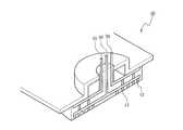
도 4는 본 발명의 일 실시예에 따른 원자층 증착 공정 장비에서의 샤워 헤드의 단면도이고, 도 5는 도 4의 샤워 헤드의 투시도이다.4 is a cross-sectional view of the shower head in the atomic layer deposition process equipment according to an embodiment of the present invention, Figure 5 is a perspective view of the shower head of FIG.
먼저, 도 4를 참조하면, 상기 샤워 헤드(100)는 산화 가스 쿨링 블록(110), 버퍼링 블록(120) 및 소스 가스 블록(130)을 구비한다.First, referring to FIG. 4, the
상기 산화 가스 쿨링 블록(110)에는 산화 가스 분사공(142)이 형성되어져 있다. 상기 산화 가스 분사공(142)은 산화 가스가 상기 원자층 증착 공정 장비에서의 반응 챔버(미도시) 내부로 주입되도록 하는 경로를 제공하는 역할을 한다. 상기 산화 가스 쿨링 블록(110)은 산화 가스를 공급하기 위한 산화 가스 공급 라인(140)에 연결되어져 있다. 그리고, 상기 샤워 헤드(100)는 냉각수(PCW) 주입구(160) 및 냉각수 배출구(162)를 더 구비할 수 있다. 이는 산화 가스가 고온 환경하에서 환원되어 버리는 현상을 방지하기 위해, 냉각수(PCW)를 상기 산화 가스 쿨링 블록(110)의 내부로 유입시키도록 하기 위함이다.An oxidizing
상기 버퍼링 블록(120)은 상기 산화 가스 분사공(142)과 연통되는 제1 분사공(122)을 구비한다. 그리고, 상기 버퍼링 블록(120)은 상기 산화 가스 쿨링 블록(110)의 하부에 배치됨으로써, 상기 산화 가스 쿨링 블록(110)이 상기 반응 챔버 내의 히팅 플레이트(heating plate)로부터의 열에 의해 가열되는 현상을 줄인다.The
상기 소스 가스 블록(130)은 상기 버퍼링 블록(120)의 하부에 배치되고 소스 가스가 상기 반응 챔버의 내부로 주입되도록 하는 경로를 제공하는 소스 가스 분사공(152)을 구비한다. 또한, 상기 소스 가스 블록(130)은 상기 버퍼링 블록(120)에 형성되어 상기 산화 가스 분사공(142)과 연통되는 제1 분사공(122)에 연통되는 제2 분사공(132)을 구비한다. 그리하여, 상기 제2 분사공(132)에 의해 상기 산화 가스가 상기 반응 챔버의 내부로 주입된다.The
상기 제2 가스 분사공(132)과 상기 소스 가스 분사공(152)은 상기 소스 가스 블록(130)에 형성되어져 있기는 하지만, 서로 구별되어지게 형성되어야 한다. 즉, 상기 제1 가스 분사공(122)과 상기 소스 가스 분사공(152)은 연통되지 않도록 형성되는 것이 바람직하다. 이는 소스 가스와 산화 가스가 웨이퍼 표면에서 원활하게 반응을 일으키도록 하기 위함이다.Although the second
상기 소스 가스는 TMA(Tri Methyl Aluminum) 가스일 수 있고, 상기 산화 가스는 오존 가스(O3) 일 수 있다. 즉, TMA 가스와 오존 가스를 웨이퍼 상에 순차적으로 흡착하면 웨이퍼 상에 알루미늄 옥사이드막 즉 산화 알루미늄이 형성된다. 오존 가스를 이용하기 위해서는 원자층 증착 장치와 오존 발생 장치를 연결하는 오존 공급라인이 필요하다.The source gas may be a tri methyl aluminum (TMA) gas, and the oxidizing gas may be an ozone gas (O 3). That is, when the TMA gas and the ozone gas are sequentially adsorbed on the wafer, an aluminum oxide film, that is, aluminum oxide, is formed on the wafer. In order to use ozone gas, an ozone supply line connecting an atomic layer deposition apparatus and an ozone generator is required.
도 4 및 도 5를 참조하여, 상기 산화 가스 쿨링 블록(110), 버퍼링 블록(120) 및 소스 가스 블록(130)들 간의 관계 및 산화 가스 분사공(142), 소스 가스 분사공(152), 제1 분사공(122), 제2 분사공(132)의 관계를 보다 상세히 설명하면 이하와 같다.4 and 5, the relationship between the oxidizing
샤워 헤드(100)에 있어서 산화 가스 공급 라인(140) 및 소스 가스 공급 라인(150)과 인접한 부분은 상기 산화 가스 쿨링 블록(110)이고, 상기 산화 가스 쿨링 블록(110)과 상기 소스 가스 블록(130)의 사이에 상기 버퍼링 블록(120)이 게재된다. 상기 각 블록들(110, 120, 130)이 일체형으로 형성되어질 수도 있으나, 상기 산화 가스 쿨링 블록(110)으로 유입되어 반응 챔버로 분출되는 산화 가스의 환원량을 줄이는 데에는 상기 각 블록들(110, 120, 130)이 소정의 간격을 유지하는 것이 바람직하다.A portion of the
상기 산화 가스 쿨링 블록(110)에는 산화 가스 분사공(142)이 형성되어져 있고, 상기 버퍼링 블록(120)에는 상기 산화 가스 분사공(142)에 연통된 제1 분사공(122)이 형성되어져 있고, 상기 제1 분사공(122)은 상기 제2 분사공(132)과 연통된다. 상기 제2 분사공(132) 및 상기 소스 가스 분사공(152)은 상기 소스 가스 블록(130)에 형성되어져 있다. 상기 소스 가스 분사공(152)은 상기 소스 가스 공급 라인(150)에 연결되어져 있다.An oxidizing
상술한 바와 같이, 본 발명은 상기 버퍼링 블록(120)에 의해 상기 산화 가스가 환원되는 현상을 줄일 수 있게 된다. 앞서 언급된 바와 같이, 반응 챔버 내의 히팅 플레이트는 공정 진행 중에 약 600℃까지 가열이 되므로, 상기 버퍼링 블록(120)이 없는 경우에는 샤워 헤드는 약 200℃까지 올라가게 됨으로 인해 산화 가스가 환원되는 현상이 빈번하게 일어났다.As described above, the present invention can reduce the phenomenon that the oxidizing gas is reduced by the
본 발명에 따른 원자층 증착 공정 장비는 상기 실시예에 한정되지 않고, 본 발명의 기본 원리를 벗어나지 않는 범위에서 다양하게 설계되고, 응용될 수 있음은 본 발명이 속하는 기술분야에서 통상의 지식을 가지는 자에게는 자명한 사실이라 할 것이다.Atomic layer deposition process equipment according to the present invention is not limited to the above embodiment, it can be variously designed and applied within the scope without departing from the basic principles of the present invention having a common knowledge in the art It will be obvious to one.
상술한 바와 같이, 본 발명은 종래의 원자층 증착 공정 장비에서의 샤워 헤드가 갖는 열 에너지에의 취약한 구조 문제를 개선하기 위한 원자층 증착 공정 장비에서의 샤워 헤드를 제공함으로써, 샤워 헤드가 공정 진행 중에 히팅 플레이트의 영향으로 인해 온도가 상승하게 되어 산화 가스가 환원되어 버리는 현상을 감소시키는 효과를 갖는다.As described above, the present invention provides a shower head in an atomic layer deposition process equipment to improve the structural problem vulnerable to the thermal energy of the shower head in a conventional atomic layer deposition process equipment, so that the shower head proceeds Due to the influence of the heating plate during the temperature rises has the effect of reducing the phenomenon that the oxidizing gas is reduced.
또한, 본 발명은 산화 물질의 환원 현상을 줄임으로써 수율을 증가시키는 효과를 갖는다.In addition, the present invention has the effect of increasing the yield by reducing the reduction phenomenon of the oxidizing material.
Claims (5)
Translated fromKoreanPriority Applications (1)
| Application Number | Priority Date | Filing Date | Title |
|---|---|---|---|
| KR1020060042261AKR20070109384A (en) | 2006-05-11 | 2006-05-11 | Shower Heads in Atomic Layer Deposition Process Equipment |
Applications Claiming Priority (1)
| Application Number | Priority Date | Filing Date | Title |
|---|---|---|---|
| KR1020060042261AKR20070109384A (en) | 2006-05-11 | 2006-05-11 | Shower Heads in Atomic Layer Deposition Process Equipment |
Publications (1)
| Publication Number | Publication Date |
|---|---|
| KR20070109384Atrue KR20070109384A (en) | 2007-11-15 |
Family
ID=39063902
Family Applications (1)
| Application Number | Title | Priority Date | Filing Date |
|---|---|---|---|
| KR1020060042261AWithdrawnKR20070109384A (en) | 2006-05-11 | 2006-05-11 | Shower Heads in Atomic Layer Deposition Process Equipment |
Country Status (1)
| Country | Link |
|---|---|
| KR (1) | KR20070109384A (en) |
Cited By (5)
| Publication number | Priority date | Publication date | Assignee | Title |
|---|---|---|---|---|
| WO2011129492A1 (en)* | 2010-04-12 | 2011-10-20 | 세메스 주식회사 | Gas injection unit and a thin-film vapour-deposition device and method using the same |
| KR101135083B1 (en)* | 2010-10-29 | 2012-04-16 | 세메스 주식회사 | Apparatus and method for depositing thin layer |
| KR101329318B1 (en)* | 2011-09-30 | 2013-11-14 | 세메스 주식회사 | Nozzle unit, apparatus and method for treating substrate with the same |
| US8821641B2 (en) | 2011-09-30 | 2014-09-02 | Samsung Electronics Co., Ltd. | Nozzle unit, and apparatus and method for treating substrate with the same |
| CN112090602A (en)* | 2020-09-24 | 2020-12-18 | 北京北方华创微电子装备有限公司 | Semiconductor process equipment and air inlet structure thereof |
- 2006
- 2006-05-11KRKR1020060042261Apatent/KR20070109384A/ennot_activeWithdrawn
Cited By (6)
| Publication number | Priority date | Publication date | Assignee | Title |
|---|---|---|---|---|
| WO2011129492A1 (en)* | 2010-04-12 | 2011-10-20 | 세메스 주식회사 | Gas injection unit and a thin-film vapour-deposition device and method using the same |
| KR101135083B1 (en)* | 2010-10-29 | 2012-04-16 | 세메스 주식회사 | Apparatus and method for depositing thin layer |
| KR101329318B1 (en)* | 2011-09-30 | 2013-11-14 | 세메스 주식회사 | Nozzle unit, apparatus and method for treating substrate with the same |
| US8821641B2 (en) | 2011-09-30 | 2014-09-02 | Samsung Electronics Co., Ltd. | Nozzle unit, and apparatus and method for treating substrate with the same |
| CN112090602A (en)* | 2020-09-24 | 2020-12-18 | 北京北方华创微电子装备有限公司 | Semiconductor process equipment and air inlet structure thereof |
| CN112090602B (en)* | 2020-09-24 | 2021-11-16 | 北京北方华创微电子装备有限公司 | Semiconductor process equipment and air inlet structure thereof |
Similar Documents
| Publication | Publication Date | Title |
|---|---|---|
| KR102662595B1 (en) | Suppressing interfacial reactions by varying wafer temperature throughout deposition | |
| TWI515763B (en) | Vertical plasma processing apparatus and method for semiconductor process | |
| KR100684910B1 (en) | Plasma processing apparatus and its cleaning method | |
| KR100824088B1 (en) | Deposition Process | |
| US20040025787A1 (en) | System for depositing a film onto a substrate using a low pressure gas precursor | |
| US20090283038A1 (en) | Film forming method and apparatus | |
| WO2005041285A1 (en) | Shower head and film-forming device using the same | |
| JP2008240158A (en) | Thin film forming method | |
| JPWO2005024928A1 (en) | Gas processing apparatus and heat dissipation method | |
| US9133548B2 (en) | TiN film forming method and storage medium | |
| WO2007114335A1 (en) | Substrate processing apparatus and substrate placing table | |
| TW201207976A (en) | Method of improving film non-uniformity and throughput | |
| TW202018776A (en) | Semiconductor device manufacturing method, substrate processing device, and recording medium | |
| KR20070109384A (en) | Shower Heads in Atomic Layer Deposition Process Equipment | |
| KR100527048B1 (en) | Method for depositing thin film on wafer | |
| JP5303984B2 (en) | Film forming apparatus and film forming method | |
| JP2007067119A (en) | Semiconductor manufacturing apparatus | |
| JP2021048233A (en) | Raw material storage system, substrate processing apparatus, cleaning method and program | |
| JP2011074413A (en) | Film deposition apparatus, film deposition method, and substrate processing apparatus | |
| JP7195190B2 (en) | Film forming method and film forming apparatus | |
| KR100937945B1 (en) | Method of manufacturing a semiconductor device | |
| KR100929535B1 (en) | Nozzle Unit and Atomic Layer Deposition Equipment with the Unit | |
| KR20210009840A (en) | Atomic layer deposition apparatus | |
| JP2004006654A (en) | Processing device and processing method | |
| JP4543611B2 (en) | Precoat layer forming method and film forming method |
Legal Events
| Date | Code | Title | Description |
|---|---|---|---|
| PA0109 | Patent application | Patent event code:PA01091R01D Comment text:Patent Application Patent event date:20060511 | |
| PG1501 | Laying open of application | ||
| PC1203 | Withdrawal of no request for examination | ||
| WITN | Application deemed withdrawn, e.g. because no request for examination was filed or no examination fee was paid |