KR20070107657A - Drive mechanism for a drug delivery device - Google Patents
Drive mechanism for a drug delivery deviceDownload PDFInfo
- Publication number
- KR20070107657A KR20070107657AKR1020077007620AKR20077007620AKR20070107657AKR 20070107657 AKR20070107657 AKR 20070107657AKR 1020077007620 AKR1020077007620 AKR 1020077007620AKR 20077007620 AKR20077007620 AKR 20077007620AKR 20070107657 AKR20070107657 AKR 20070107657A
- Authority
- KR
- South Korea
- Prior art keywords
- plunger rod
- dose setting
- drive mechanism
- inner cylinder
- drug delivery
- Prior art date
- Legal status (The legal status is an assumption and is not a legal conclusion. Google has not performed a legal analysis and makes no representation as to the accuracy of the status listed.)
- Granted
Links
- 230000007246mechanismEffects0.000titleclaimsabstractdescription29
- 238000012377drug deliveryMethods0.000titleclaimsabstractdescription28
- 230000033001locomotionEffects0.000claimsdescription24
- NOESYZHRGYRDHS-UHFFFAOYSA-NinsulinChemical compoundN1C(=O)C(NC(=O)C(CCC(N)=O)NC(=O)C(CCC(O)=O)NC(=O)C(C(C)C)NC(=O)C(NC(=O)CN)C(C)CC)CSSCC(C(NC(CO)C(=O)NC(CC(C)C)C(=O)NC(CC=2C=CC(O)=CC=2)C(=O)NC(CCC(N)=O)C(=O)NC(CC(C)C)C(=O)NC(CCC(O)=O)C(=O)NC(CC(N)=O)C(=O)NC(CC=2C=CC(O)=CC=2)C(=O)NC(CSSCC(NC(=O)C(C(C)C)NC(=O)C(CC(C)C)NC(=O)C(CC=2C=CC(O)=CC=2)NC(=O)C(CC(C)C)NC(=O)C(C)NC(=O)C(CCC(O)=O)NC(=O)C(C(C)C)NC(=O)C(CC(C)C)NC(=O)C(CC=2NC=NC=2)NC(=O)C(CO)NC(=O)CNC2=O)C(=O)NCC(=O)NC(CCC(O)=O)C(=O)NC(CCCNC(N)=N)C(=O)NCC(=O)NC(CC=3C=CC=CC=3)C(=O)NC(CC=3C=CC=CC=3)C(=O)NC(CC=3C=CC(O)=CC=3)C(=O)NC(C(C)O)C(=O)N3C(CCC3)C(=O)NC(CCCCN)C(=O)NC(C)C(O)=O)C(=O)NC(CC(N)=O)C(O)=O)=O)NC(=O)C(C(C)CC)NC(=O)C(CO)NC(=O)C(C(C)O)NC(=O)C1CSSCC2NC(=O)C(CC(C)C)NC(=O)C(NC(=O)C(CCC(N)=O)NC(=O)C(CC(N)=O)NC(=O)C(NC(=O)C(N)CC=1C=CC=CC=1)C(C)C)CC1=CN=CN1NOESYZHRGYRDHS-UHFFFAOYSA-N0.000claimsdescription9
- 238000000034methodMethods0.000claimsdescription5
- 102000004877InsulinHuman genes0.000claimsdescription4
- 108090001061InsulinProteins0.000claimsdescription4
- 229940125396insulinDrugs0.000claimsdescription4
- HTTJABKRGRZYRN-UHFFFAOYSA-NHeparinChemical compoundOC1C(NC(=O)C)C(O)OC(COS(O)(=O)=O)C1OC1C(OS(O)(=O)=O)C(O)C(OC2C(C(OS(O)(=O)=O)C(OC3C(C(O)C(O)C(O3)C(O)=O)OS(O)(=O)=O)C(CO)O2)NS(O)(=O)=O)C(C(O)=O)O1HTTJABKRGRZYRN-UHFFFAOYSA-N0.000claimsdescription3
- 229960002897heparinDrugs0.000claimsdescription3
- 229920000669heparinPolymers0.000claimsdescription3
- 238000004519manufacturing processMethods0.000claimsdescription2
- 239000008177pharmaceutical agentSubstances0.000claims1
- 239000000825pharmaceutical preparationSubstances0.000claims1
- 239000003814drugSubstances0.000abstractdescription15
- 229940079593drugDrugs0.000abstractdescription13
- 230000005540biological transmissionEffects0.000abstractdescription3
- 238000002347injectionMethods0.000description8
- 239000007924injectionSubstances0.000description8
- 239000011295pitchSubstances0.000description7
- 239000007788liquidSubstances0.000description6
- 230000008878couplingEffects0.000description3
- 238000010168coupling processMethods0.000description3
- 238000005859coupling reactionMethods0.000description3
- 238000010276constructionMethods0.000description2
- 239000000356contaminantSubstances0.000description2
- 238000013461designMethods0.000description2
- 239000000428dustSubstances0.000description2
- 239000012530fluidSubstances0.000description2
- 230000004048modificationEffects0.000description2
- 238000012986modificationMethods0.000description2
- 230000009467reductionEffects0.000description2
- 239000000243solutionSubstances0.000description2
- 208000010415Low VisionDiseases0.000description1
- 230000002785anti-thrombosisEffects0.000description1
- 239000003146anticoagulant agentSubstances0.000description1
- 230000008901benefitEffects0.000description1
- 230000026058directional locomotionEffects0.000description1
- 239000011521glassSubstances0.000description1
- 239000000122growth hormoneSubstances0.000description1
- 229940088597hormoneDrugs0.000description1
- 239000005556hormoneSubstances0.000description1
- 238000001802infusionMethods0.000description1
- 238000003780insertionMethods0.000description1
- 230000037431insertionEffects0.000description1
- 239000003055low molecular weight heparinSubstances0.000description1
- 230000004303low visionEffects0.000description1
- 229940127215low-molecular weight heparinDrugs0.000description1
- 229940126601medicinal productDrugs0.000description1
- 239000008194pharmaceutical compositionSubstances0.000description1
- 238000004064recyclingMethods0.000description1
- 239000000725suspensionSubstances0.000description1
- 229960005486vaccineDrugs0.000description1
Images


Classifications
- A—HUMAN NECESSITIES
- A61—MEDICAL OR VETERINARY SCIENCE; HYGIENE
- A61M—DEVICES FOR INTRODUCING MEDIA INTO, OR ONTO, THE BODY; DEVICES FOR TRANSDUCING BODY MEDIA OR FOR TAKING MEDIA FROM THE BODY; DEVICES FOR PRODUCING OR ENDING SLEEP OR STUPOR
- A61M5/00—Devices for bringing media into the body in a subcutaneous, intra-vascular or intramuscular way; Accessories therefor, e.g. filling or cleaning devices, arm-rests
- A61M5/178—Syringes
- A61M5/31—Details
- A61M5/315—Pistons; Piston-rods; Guiding, blocking or restricting the movement of the rod or piston; Appliances on the rod for facilitating dosing ; Dosing mechanisms
- A61M5/31533—Dosing mechanisms, i.e. setting a dose
- A61M5/31545—Setting modes for dosing
- A61M5/31548—Mechanically operated dose setting member
- A61M5/3155—Mechanically operated dose setting member by rotational movement of dose setting member, e.g. during setting or filling of a syringe
- A61M5/31551—Mechanically operated dose setting member by rotational movement of dose setting member, e.g. during setting or filling of a syringe including axial movement of dose setting member
- A—HUMAN NECESSITIES
- A61—MEDICAL OR VETERINARY SCIENCE; HYGIENE
- A61M—DEVICES FOR INTRODUCING MEDIA INTO, OR ONTO, THE BODY; DEVICES FOR TRANSDUCING BODY MEDIA OR FOR TAKING MEDIA FROM THE BODY; DEVICES FOR PRODUCING OR ENDING SLEEP OR STUPOR
- A61M5/00—Devices for bringing media into the body in a subcutaneous, intra-vascular or intramuscular way; Accessories therefor, e.g. filling or cleaning devices, arm-rests
- A61M5/178—Syringes
- A61M5/31—Details
- A61M5/315—Pistons; Piston-rods; Guiding, blocking or restricting the movement of the rod or piston; Appliances on the rod for facilitating dosing ; Dosing mechanisms
- A—HUMAN NECESSITIES
- A61—MEDICAL OR VETERINARY SCIENCE; HYGIENE
- A61M—DEVICES FOR INTRODUCING MEDIA INTO, OR ONTO, THE BODY; DEVICES FOR TRANSDUCING BODY MEDIA OR FOR TAKING MEDIA FROM THE BODY; DEVICES FOR PRODUCING OR ENDING SLEEP OR STUPOR
- A61M5/00—Devices for bringing media into the body in a subcutaneous, intra-vascular or intramuscular way; Accessories therefor, e.g. filling or cleaning devices, arm-rests
- A61M5/178—Syringes
- A61M5/30—Syringes for injection by jet action, without needle, e.g. for use with replaceable ampoules or carpules
- A—HUMAN NECESSITIES
- A61—MEDICAL OR VETERINARY SCIENCE; HYGIENE
- A61M—DEVICES FOR INTRODUCING MEDIA INTO, OR ONTO, THE BODY; DEVICES FOR TRANSDUCING BODY MEDIA OR FOR TAKING MEDIA FROM THE BODY; DEVICES FOR PRODUCING OR ENDING SLEEP OR STUPOR
- A61M5/00—Devices for bringing media into the body in a subcutaneous, intra-vascular or intramuscular way; Accessories therefor, e.g. filling or cleaning devices, arm-rests
- A61M5/178—Syringes
- A61M5/31—Details
- A61M5/315—Pistons; Piston-rods; Guiding, blocking or restricting the movement of the rod or piston; Appliances on the rod for facilitating dosing ; Dosing mechanisms
- A61M5/31501—Means for blocking or restricting the movement of the rod or piston
- A—HUMAN NECESSITIES
- A61—MEDICAL OR VETERINARY SCIENCE; HYGIENE
- A61M—DEVICES FOR INTRODUCING MEDIA INTO, OR ONTO, THE BODY; DEVICES FOR TRANSDUCING BODY MEDIA OR FOR TAKING MEDIA FROM THE BODY; DEVICES FOR PRODUCING OR ENDING SLEEP OR STUPOR
- A61M5/00—Devices for bringing media into the body in a subcutaneous, intra-vascular or intramuscular way; Accessories therefor, e.g. filling or cleaning devices, arm-rests
- A61M5/178—Syringes
- A61M5/31—Details
- A61M5/315—Pistons; Piston-rods; Guiding, blocking or restricting the movement of the rod or piston; Appliances on the rod for facilitating dosing ; Dosing mechanisms
- A61M5/31511—Piston or piston-rod constructions, e.g. connection of piston with piston-rod
- A—HUMAN NECESSITIES
- A61—MEDICAL OR VETERINARY SCIENCE; HYGIENE
- A61M—DEVICES FOR INTRODUCING MEDIA INTO, OR ONTO, THE BODY; DEVICES FOR TRANSDUCING BODY MEDIA OR FOR TAKING MEDIA FROM THE BODY; DEVICES FOR PRODUCING OR ENDING SLEEP OR STUPOR
- A61M5/00—Devices for bringing media into the body in a subcutaneous, intra-vascular or intramuscular way; Accessories therefor, e.g. filling or cleaning devices, arm-rests
- A61M5/178—Syringes
- A61M5/31—Details
- A61M5/315—Pistons; Piston-rods; Guiding, blocking or restricting the movement of the rod or piston; Appliances on the rod for facilitating dosing ; Dosing mechanisms
- A61M5/31525—Dosing
- A61M5/31528—Dosing by means of rotational movements, e.g. screw-thread mechanisms
- A—HUMAN NECESSITIES
- A61—MEDICAL OR VETERINARY SCIENCE; HYGIENE
- A61M—DEVICES FOR INTRODUCING MEDIA INTO, OR ONTO, THE BODY; DEVICES FOR TRANSDUCING BODY MEDIA OR FOR TAKING MEDIA FROM THE BODY; DEVICES FOR PRODUCING OR ENDING SLEEP OR STUPOR
- A61M5/00—Devices for bringing media into the body in a subcutaneous, intra-vascular or intramuscular way; Accessories therefor, e.g. filling or cleaning devices, arm-rests
- A61M5/178—Syringes
- A61M5/31—Details
- A61M5/315—Pistons; Piston-rods; Guiding, blocking or restricting the movement of the rod or piston; Appliances on the rod for facilitating dosing ; Dosing mechanisms
- A61M5/31565—Administration mechanisms, i.e. constructional features, modes of administering a dose
- A61M5/31576—Constructional features or modes of drive mechanisms for piston rods
- A61M5/31578—Constructional features or modes of drive mechanisms for piston rods based on axial translation, i.e. components directly operatively associated and axially moved with plunger rod
- A61M5/3158—Constructional features or modes of drive mechanisms for piston rods based on axial translation, i.e. components directly operatively associated and axially moved with plunger rod performed by axially moving actuator operated by user, e.g. an injection button
- A—HUMAN NECESSITIES
- A61—MEDICAL OR VETERINARY SCIENCE; HYGIENE
- A61M—DEVICES FOR INTRODUCING MEDIA INTO, OR ONTO, THE BODY; DEVICES FOR TRANSDUCING BODY MEDIA OR FOR TAKING MEDIA FROM THE BODY; DEVICES FOR PRODUCING OR ENDING SLEEP OR STUPOR
- A61M5/00—Devices for bringing media into the body in a subcutaneous, intra-vascular or intramuscular way; Accessories therefor, e.g. filling or cleaning devices, arm-rests
- A61M5/178—Syringes
- A61M5/31—Details
- A61M5/315—Pistons; Piston-rods; Guiding, blocking or restricting the movement of the rod or piston; Appliances on the rod for facilitating dosing ; Dosing mechanisms
- A61M5/31565—Administration mechanisms, i.e. constructional features, modes of administering a dose
- A61M5/31576—Constructional features or modes of drive mechanisms for piston rods
- A61M5/31583—Constructional features or modes of drive mechanisms for piston rods based on rotational translation, i.e. movement of piston rod is caused by relative rotation between the user activated actuator and the piston rod
- A61M5/31585—Constructional features or modes of drive mechanisms for piston rods based on rotational translation, i.e. movement of piston rod is caused by relative rotation between the user activated actuator and the piston rod performed by axially moving actuator, e.g. an injection button
- A—HUMAN NECESSITIES
- A61—MEDICAL OR VETERINARY SCIENCE; HYGIENE
- A61M—DEVICES FOR INTRODUCING MEDIA INTO, OR ONTO, THE BODY; DEVICES FOR TRANSDUCING BODY MEDIA OR FOR TAKING MEDIA FROM THE BODY; DEVICES FOR PRODUCING OR ENDING SLEEP OR STUPOR
- A61M2202/00—Special media to be introduced, removed or treated
- A61M2202/04—Liquids
- A61M2202/0468—Liquids non-physiological
- A61M2202/0478—Heparin
- A—HUMAN NECESSITIES
- A61—MEDICAL OR VETERINARY SCIENCE; HYGIENE
- A61M—DEVICES FOR INTRODUCING MEDIA INTO, OR ONTO, THE BODY; DEVICES FOR TRANSDUCING BODY MEDIA OR FOR TAKING MEDIA FROM THE BODY; DEVICES FOR PRODUCING OR ENDING SLEEP OR STUPOR
- A61M2207/00—Methods of manufacture, assembly or production
- A—HUMAN NECESSITIES
- A61—MEDICAL OR VETERINARY SCIENCE; HYGIENE
- A61M—DEVICES FOR INTRODUCING MEDIA INTO, OR ONTO, THE BODY; DEVICES FOR TRANSDUCING BODY MEDIA OR FOR TAKING MEDIA FROM THE BODY; DEVICES FOR PRODUCING OR ENDING SLEEP OR STUPOR
- A61M5/00—Devices for bringing media into the body in a subcutaneous, intra-vascular or intramuscular way; Accessories therefor, e.g. filling or cleaning devices, arm-rests
- A61M5/178—Syringes
- A61M5/24—Ampoule syringes, i.e. syringes with needle for use in combination with replaceable ampoules or carpules, e.g. automatic
- A—HUMAN NECESSITIES
- A61—MEDICAL OR VETERINARY SCIENCE; HYGIENE
- A61M—DEVICES FOR INTRODUCING MEDIA INTO, OR ONTO, THE BODY; DEVICES FOR TRANSDUCING BODY MEDIA OR FOR TAKING MEDIA FROM THE BODY; DEVICES FOR PRODUCING OR ENDING SLEEP OR STUPOR
- A61M5/00—Devices for bringing media into the body in a subcutaneous, intra-vascular or intramuscular way; Accessories therefor, e.g. filling or cleaning devices, arm-rests
- A61M5/178—Syringes
- A61M5/31—Details
- A61M5/315—Pistons; Piston-rods; Guiding, blocking or restricting the movement of the rod or piston; Appliances on the rod for facilitating dosing ; Dosing mechanisms
- A61M5/31533—Dosing mechanisms, i.e. setting a dose
- A61M5/31545—Setting modes for dosing
- A61M5/31548—Mechanically operated dose setting member
- A61M5/31556—Accuracy improving means
- A61M5/31558—Accuracy improving means using scaling up or down transmissions, e.g. gearbox
- A—HUMAN NECESSITIES
- A61—MEDICAL OR VETERINARY SCIENCE; HYGIENE
- A61M—DEVICES FOR INTRODUCING MEDIA INTO, OR ONTO, THE BODY; DEVICES FOR TRANSDUCING BODY MEDIA OR FOR TAKING MEDIA FROM THE BODY; DEVICES FOR PRODUCING OR ENDING SLEEP OR STUPOR
- A61M5/00—Devices for bringing media into the body in a subcutaneous, intra-vascular or intramuscular way; Accessories therefor, e.g. filling or cleaning devices, arm-rests
- A61M5/178—Syringes
- A61M5/31—Details
- A61M5/315—Pistons; Piston-rods; Guiding, blocking or restricting the movement of the rod or piston; Appliances on the rod for facilitating dosing ; Dosing mechanisms
- A61M5/31565—Administration mechanisms, i.e. constructional features, modes of administering a dose
- A61M5/31566—Means improving security or handling thereof
- A61M5/31573—Accuracy improving means
- A61M5/31575—Accuracy improving means using scaling up or down transmissions, e.g. gearbox
- A—HUMAN NECESSITIES
- A61—MEDICAL OR VETERINARY SCIENCE; HYGIENE
- A61M—DEVICES FOR INTRODUCING MEDIA INTO, OR ONTO, THE BODY; DEVICES FOR TRANSDUCING BODY MEDIA OR FOR TAKING MEDIA FROM THE BODY; DEVICES FOR PRODUCING OR ENDING SLEEP OR STUPOR
- A61M5/00—Devices for bringing media into the body in a subcutaneous, intra-vascular or intramuscular way; Accessories therefor, e.g. filling or cleaning devices, arm-rests
- A61M5/178—Syringes
- A61M5/31—Details
- A61M5/315—Pistons; Piston-rods; Guiding, blocking or restricting the movement of the rod or piston; Appliances on the rod for facilitating dosing ; Dosing mechanisms
- A61M5/31565—Administration mechanisms, i.e. constructional features, modes of administering a dose
- A61M5/31576—Constructional features or modes of drive mechanisms for piston rods
- A61M5/31583—Constructional features or modes of drive mechanisms for piston rods based on rotational translation, i.e. movement of piston rod is caused by relative rotation between the user activated actuator and the piston rod
- A61M5/31586—Constructional features or modes of drive mechanisms for piston rods based on rotational translation, i.e. movement of piston rod is caused by relative rotation between the user activated actuator and the piston rod performed by rotationally moving or pivoted actuator, e.g. an injection lever or handle
Landscapes
- Health & Medical Sciences (AREA)
- Vascular Medicine (AREA)
- Engineering & Computer Science (AREA)
- Anesthesiology (AREA)
- Biomedical Technology (AREA)
- Heart & Thoracic Surgery (AREA)
- Hematology (AREA)
- Life Sciences & Earth Sciences (AREA)
- Animal Behavior & Ethology (AREA)
- General Health & Medical Sciences (AREA)
- Public Health (AREA)
- Veterinary Medicine (AREA)
- Infusion, Injection, And Reservoir Apparatuses (AREA)
- Medical Treatment And Welfare Office Work (AREA)
- Medicines That Contain Protein Lipid Enzymes And Other Medicines (AREA)
Abstract
Description
Translated fromKorean본 발명은 투여가능한 약의 다중 투여를 사용자가 선택할 수 있게 하는 약 전달 장치를 위한, 약의 설정된 투여량을 분배하기 위한 및 바람직하게는 주사에 의해 환자에 상기 약을 투여하기 위한 구동 기구에 대한 것이다. 특히, 본 발명은 환자 자신이 취급하는 이러한 장치에 대한 것이다.The present invention relates to a drug delivery device that allows a user to select multiple doses of an administrable drug, to a drive mechanism for dispensing a set dose of a drug and preferably to the patient by injection. will be. In particular, the present invention relates to such a device handled by the patient himself.
필요한 투여량의 액체 약을 여러번 투여할 수 있게 하고 액체를 환자에게 주입할 수 있게 하는 약 전달 장치들이 당업계에 공지되어 있다. 일반적으로, 이러한 장치들은 평범한 주사기와 실질적으로 동일한 목적을 갖는다.Drug delivery devices are known in the art that allow multiple administrations of the liquid dosage of the required dosage and infusion of the liquid into the patient. In general, these devices serve substantially the same purpose as ordinary syringes.
이러한 종류의 주사기들은 사용자의 필요성들을 만족하기 위해 다수의 요구조건들을 만족해야 한다. 이들 장치는 구조가 튼튼하면서 사용자가 작동시에 이해하기 쉽고 부품들의 조작하기 쉬워야 한다. 당뇨병 환자들의 경우, 많은 사용자들이 신체적으로 허약하고 시력이 약할 수 있다. 주사기가 재사용가능한 것이 아닌 1회용인 경우, 주사기는 저렴하게 제조가능하고 폐기하기 쉬워야 한다(바람직하게는 재활용하기 적합하다).Syringes of this kind must meet a number of requirements in order to meet the needs of the user. These devices must be robust in construction and easy for the user to understand at the time of operation and the handling of parts. In diabetics, many users may be physically weak and have low vision. If the syringe is disposable rather than reusable, the syringe should be inexpensive to manufacture and easy to dispose of (preferably suitable for recycling).
WO 9114467 A1호는 그 사이에 나사결합하지 않는 세그먼트들과 함께 등간격으로 이격된 나사를 갖는 세그먼트들을 갖는 제 1 및 제 2 나사 부재로 구성된 망 원경식 피스톤 로드를 갖는 구동 기구를 포함하는 분배 장치를 공개한다. 이 장치는 투여량 설정 슬리브를 추가로 포함하며, 이는 회전을 위해 커플링되는 제 2 나사 부재를 둘러싸고 장치의 외각(shell)과 나사결합한다. 3개의 상기 구성요소들의 나사들은 동일한 리드(lead)를 갖는다. 이 장치의 디자인은 비교적 큰 투여량을 분배하게 하기 위해 약 1:1의 본체 길이 대 플런져(plunger) 길이 비를 요구한다. 그러나, 환자에 의해 설정된 과다 투여량의 간단하고 안전한 수정은 카트리지의 해체(dismantling) 또는 유체의 설정량의 분배없이는 해결되지 않은 채로 남았다.WO 9114467 A1 discloses a dispensing device comprising a drive mechanism having a telescopic piston rod consisting of first and second threaded members having segments with screws spaced at equal intervals with segments not threaded therebetween. To the public. The device further includes a dose setting sleeve, which is threaded with the shell of the device surrounding the second threaded member that is coupled for rotation. The screws of the three said components have the same lead. The design of this device requires a ratio of body length to plunger length of about 1: 1 to allow for dispensing relatively large doses. However, a simple and safe modification of the overdose set by the patient remained unresolved without dismantling the cartridge or dispensing the set amount of fluid.
WO 9938554 A2호는 카트리지로부터 약물의 설정된 투여량들을 배분하는 주사기(injection syringe)를 설명하며, 여기서 카트리지를 해제할 필요 또는 설정된 양의 유체를 분배하지 않고 설정된 과다투여량을 수정할 수 있게 하는 단방향 커플링[래칫(ratchet)]을 포함하는 구동 기구가 공개된다. 또한 이 장치는 투여량 분배 중에 단방향 커플링이 회전될 수 있기 전에 초기 저항(reluctance)이 되어야 하도록 설계되어 있다.WO 9938554 A2 describes an injection syringe for dispensing set doses of a drug from a cartridge, wherein a unidirectional couple allows correcting the set overdose without dispensing the cartridge or dispensing a set amount of fluid. A drive mechanism is disclosed that includes a ring (ratchet). The device is also designed to have an initial reluctance before the unidirectional coupling can be rotated during dose dispensing.
WO 0195959 A1호는 카트리지로부터 설정된 투여량들의 약물을 주사하기 위한 주사 장치를 공개하며, 이 주사기에서 투여량이 나사가 형성된 피스톤 로드를 따라 너트를 조여 설정되어, 그 드럼의 원통면상에서 나선을 따라 지지되며 그 눈금(scale)의 숫자가 설정되는 투여량에 상응하는 투여량 설정 드럼이 주사기의 하우징의 창(window)에서 보이고, 주사기의 단부상에 올라와 있는 주사 버튼이 너트의 축방향 이동보다 큰 거리만큼 축방향으로 이동한다. 기어 휠 전달이 너트와 주사 버튼 사이에 형성되어 전동장치(gearing)가 버튼을 보다 크게 움직이게 하고 주 사 버튼에 가해져야 하는 힘이 상응하여 감소된다.WO 0195959 A1 discloses an injection device for injecting a set dose of drug from a cartridge, in which a dose is set by tightening a nut along a threaded piston rod, supported by a spiral on the cylindrical surface of the drum. The dose setting drum is shown in the window of the syringe's housing and the injection button on the end of the syringe is greater than the axial movement of the nut. Move in the axial direction by A gear wheel transmission is formed between the nut and the injection button, which allows the gearing to move the button larger and the force applied to the injection button is correspondingly reduced.
따라서, 본 발명이 해결할 문제점은 약 분배 중에 특히 많은 투여량을 분배할 때 요구되는 작동력(주사력)을 감소시키면서 컴팩트한 디자인을 유지하여 사용자 취급성을 개선하고 사용자에게 직관적이고 안전하며 설정 투여량을 쉽게 수정하는 수단을 제공하는 것이다.Therefore, the problem to be solved by the present invention is to maintain the compact design while reducing the operating force (injection force) required when dispensing large doses, especially during drug dispensing, to improve user handling and to be intuitive, safe and set dose to the user. It is to provide a means to easily modify.
그러므로, 본 발명의 목적은 약 전달 장치들, 특히 예를 들어, 펜-타입 형상의 컴팩트한 장치들에 작동력을 효과적으로 전달하기에 적합한, 기존에 기술들에 대한 대안인 구동 기구를 제공하는 것이며, 이는 부가적으로 많은 투여량의 약을 분배할 수 있게 하고 직관적이며 설정 투여량을 수정하기 쉽다는 장점을 추가로 제공한다.It is therefore an object of the present invention to provide a drive mechanism which is an alternative to the existing techniques, which is suitable for effectively transmitting the actuation force to drug delivery devices, in particular compact devices of eg pen-type shape, This additionally provides the advantage of being able to dispense large doses of the drug and being intuitive and easy to modify the set dose.
본 발명의 제 1 특징은:A first feature of the invention is:
비-원형의 단면을 갖고 중공이며 회전이 방지된 플런져 로드(plunger rod);A plunger rod having a non-circular cross section and hollow and prevented from rotation;
상기 플런져 로드와 결합하는 리드 스크류(lead screw);A lead screw coupled to the plunger rod;
투여량 설정 중에 선단부를 향해 회전운동하고 투여량 분배 중에 말단부를 향해 회전운동하는 투여량 설정 다이얼;A dose setting dial that rotates toward the distal end during dose setting and rotates toward the distal end during dose dispensing;
투여량 설정 다이얼에 해제가능하게 연결되어 상기 투여량 설정 다이얼과 내부 실린더 간의 상대회전이 투여량 설정 중에 방지되지만 투여량 분배 중에는 허용되는 내부 실린더;An inner cylinder releasably connected to a dose setting dial such that relative rotation between the dose setting dial and the inner cylinder is prevented during dose setting but permitted during dose dispensing;
상기 플런져 로드가 투여량 설정 중에 선단부를 향해 이동하는 것을 막지만, 투여량 분배중에는 상기 플런져 로드가 말단부를 향해 이동하는 것을 허용하는 플런져 로드 홀더를 포함하고;A plunger rod holder which prevents the plunger rod from moving towards the tip during dose setting but allows the plunger rod to move toward the distal end during dose dispensing;
프리 로크(free lock)를 선택적으로 추가로 포함하는 약 전달 장치용 구동 기구를 제공하는 것이다.It is to provide a drive mechanism for a drug delivery device that optionally further includes a free lock.
본 발명의 제 2 특징은 본 발명에 따른 구동 기구를 포함하는 약 전달 장치이다.A second feature of the invention is a drug delivery device comprising a drive mechanism according to the invention.
본 발명의 제 3 특징은 본 발명에 따른 장치를 조립하는 방법에서 본 발명에 따른 구동 기구의 사용하는 것이다.A third feature of the invention is the use of a drive mechanism according to the invention in a method of assembling a device according to the invention.
본 발명의 제 4 특징은 인체 또는 동물의 몸에 의약 제재를 투여하기 위해 본 발명에 따른 장치의 구동 기구를 사용하는 것이다.A fourth feature of the invention is the use of a drive mechanism of the device according to the invention for administering a medicinal product to the human or animal body.
본 발명의 다른 특징은 약 전달 장치를 조립하기 위해 임의의 구성요소들에 본 발명에 따른 기구를 장착하는 단계를 포함하는 본 발명에 따른 약 전달 장치를 조립하는 방법이다.Another feature of the present invention is a method of assembling a drug delivery device according to the present invention comprising the step of mounting the instrument according to the invention on any component for assembling the drug delivery device.
본 발명을 정의하기 위해 사용되는 용어들은 일반적으로 당업자의 상식에 따라 이해되어야 한다. 또한, 하기의 용어들은 본 발명에 따른 선택적으로 선호되는 하기의 의미를 가져야 한다.Terms used to define the present invention should generally be understood according to the common knowledge of those skilled in the art. In addition, the following terms should have the following meanings which are optionally preferred in accordance with the present invention.
본 발명에 따른 용어 "약 전달 장치"는 선택된 투여량의 약물, 예를 들어, 자가-투여(self-administration) 에 선택적으로 적합한, 인슐린, 인슐린 유사체, 성장 호르몬, 저 분자량 헤파린 및 이들의 유도체 등을 분배하게 설계된 다중-투여, 1회용, 이동형, 휴대형 장치를 의미한다. 상기 장치는 기계적 펜-타입이다. 바람직하게는, 용어 "약 전달 장치"는 정식 의학적 훈련을 받지 않은 사람, 예를 들어, 환자가 정기적으로 주사하기 위해 설계된 기계적 투여량 전달 및 투여량 선택 기구를 갖는 1회용, 다중0투여, 펜-타입 장치를 의미한다. 통상적으로, 본 발명의 "약 전달 장치"는 카트리지를 포함하며, 이는 의약 제재를 담고, 니들(needle), 그리고 선택적으로는 카트리지 홀더를 통해 투여될 수 있다.The term “drug delivery device” according to the invention refers to insulin, insulin analogues, growth hormones, low molecular weight heparin and derivatives thereof, which are optionally suitable for a selected dose of drug, for example self-administration, and the like. Means a multi-dose, disposable, mobile, portable device designed to dispense The device is a mechanical pen-type. Preferably, the term “drug delivery device” is a disposable, multi-dose, pen having a mechanical dose delivery and dose selection mechanism designed for regular injections by a person who has not been formally trained, for example, a patient. -Type device. Typically, the "drug delivery device" of the present invention includes a cartridge, which contains a medication and may be administered via a needle, and optionally via a cartridge holder.
용어 "의약 제재(pharmaceutical formulation)"는 바람직하게는 약 또는 백신을 포함하는, 카트리지에 담기는 액체 또는 현탁액 등을 의미한다. 바람직하게는, 약은 인슐린, 헤파린, 이들의 유도체, 유사체 및 대체품으로 구성되는 그룹으로부터 특히 선택되는 하나 이상의 호르몬 또는 항혈전제(antithrombotic)이다.The term "pharmaceutical formulation" means a liquid or suspension in a cartridge, preferably containing a drug or vaccine. Preferably, the drug is one or more hormones or antithrombotic particularly selected from the group consisting of insulin, heparin, derivatives, analogs and substitutes thereof.
본 발명에 따른 용어 "하우징"은 바람직하게는 외부 또는 내부("인서트") 커버를 의미한다. 하우징은 약 전달 장치(예를 들어, 구동 장치)의 안전하고 정확하고 편안한 취급이 가능하도록 설계될 수 있다. 통상적으로, 액체, 먼지, 오물 등과 같은 오염물질에 대한 노출을 제한하여 약 전달 장치(예를 들어, 구동 장치)의 구성요소들 또는 내부 기구(들)와 결합, 안내, 보호, 고정, 및/또는 수납하게 설계된다. 일반적으로, 하우징은 관형(tubular) 또는 비-관형 형상의 단일 또는 다중 부품 구성요소일 수 있다. 바람직하게는, "하우징"은 카트리지, 선택적으로 바람직하게는 하우징의 말단부에 장착되는 카트리지 홀더를 담게 설계된다.The term "housing" according to the invention preferably means an outer or inner ("insert") cover. The housing may be designed to allow safe, accurate and comfortable handling of the drug delivery device (eg, drive device). Typically, exposure to contaminants such as liquids, dust, dirt, and the like is combined, guided, protected, fixed, and / or with components or internal instrument (s) of the drug delivery device (eg, drive). Or designed to receive. In general, the housing may be a single or multi-component component of tubular or non-tubular shape. Preferably, the "housing" is designed to contain a cartridge, optionally a cartridge holder, preferably mounted at the distal end of the housing.
본 발명에 따른 용어"결합"은 구동 기구/약 전달 장치의 2개 이상의 구성요소들의 맞물림(interlocking), 바람직하게는 구성요소들의 스크류 구조물의 맞물림을 의미한다.The term "coupling" according to the invention means the interlocking of two or more components of the drive mechanism / drug delivery device, preferably the screw structure of the components.
본 발명에 따른 용어 "스크류 구조물"은 구성요소들 간의 연속적인 자유 회전 및/또는 축방향 운동을 허용하게 설계된 실질적으로 삼각형 또는 정사각형 또는 라운딩된 단면을 갖는, 약 전달 장치의 구성요소의 내부 및/또는 외부 표면에 위치하는 전체 또는 부분적 나사(thread), 예를 들어 원통형 나선 리브(rib)/홈을 의미한다. 선택적으로, 스크류 구조물은 일 방향에서 특정 구성요소들의 회전 또는 축방향 운동을 방지하게 추가로 설계될 수 있다. 스크류 구조물들은 나사 인서트와 투여량 설정 다이얼 사이에(이후 "제 1 구조물"), 내부 실린더와 프리 로크(이후 "제 2 구조물"), 리드 스크류와 플런져 로드 사이에(이후 "제 3 구조물") 포함될 수 있다. 본 발명에 따른 상기 스크류 구조물들은 바람직하게는 투여량 전달 중에 선단부로부터 말단부까지 힘을 전달하게 하는 상이한 스크류 피치들을 갖는다. 그러므로, 제 1, 제 2, 제 3 스크류 구조물들 간의 스크류 피치 비는 약 1.8 내지 4.2:1.8 내지 4.2:1, 바람직하게는 약 2.4 내지 3.6:2.4 내지 3.6:1이다. 또한, 제 1 스크류 구조물과 제 2 스크류 구조물 간의 스크류 피치들은 같은 것이 바람직하다.The term "screw structure" according to the present invention has a substantially triangular or square or rounded cross section designed to allow continuous free rotation and / or axial movement between the components, and / or the inside of the component of the drug delivery device. Or full or partial thread, for example cylindrical spiral ribs / grooves, located on the outer surface. Optionally, the screw structure can be further designed to prevent rotation or axial movement of certain components in one direction. Screw structures are provided between the screw insert and the dose setting dial (hereinafter "first structure"), the inner cylinder and free lock (hereafter "second structure"), between the lead screw and the plunger rod (hereafter "third structure"). ) May be included. The screw structures according to the invention preferably have different screw pitches which allow the force to be transmitted from the tip to the tip during dose delivery. Therefore, the screw pitch ratio between the first, second and third screw structures is about 1.8 to 4.2: 1.8 to 4.2: 1, preferably about 2.4 to 3.6: 2.4 to 3.6: 1. Also, the screw pitches between the first screw structure and the second screw structure are preferably the same.
본 발명에 따른 용어 "투여량 설정 다이얼"은 제 1 스크류 구조물에 의해 하우징과 외부 나사 결합하여 투여량 설정 다이얼이 투여량 설정 중에 선단부를 향해 회전 운동하고 투여량 분배 중에 말단부를 향해 회전운동하게 하는 실질적으로 원형 단면의 실질적으로 관형인 구성요소를 의미한다. 본 발명에 따른 "투여량 설정 다이얼"은 분배가능한 제품(예를 들어, 약)의 선택된 투여량을 표시하게 설계된다. 이는 투여량 설정 다이얼, 주행거리계(odometer) 등의 외부표면에 예를 들어, 인쇄된 표시(marking),기호, 숫자 등을 사용하여 달성될 수 있다.The term "dose setting dial" according to the present invention refers to an external screw engagement with the housing by a first screw structure such that the dose setting dial rotates toward the distal end during dose setting and rotates toward the distal end during dose dispensing. By a substantially tubular component of a substantially circular cross section. The “dose setting dial” according to the present invention is designed to indicate a selected dose of a dispensable product (eg, a drug). This can be accomplished using, for example, markings, symbols, numbers, etc. printed on external surfaces such as dose setting dials, odometers and the like.
부가적으로, 투여량 설정 다이얼은 클러치 수단에 의해 내부 실린더에 해제가능하게 연결된다. 투여량을 설정하기 위해, 투여량 설정 다이얼이 회전되고 투여량 설정 다이얼과 내부 실린더가 선단부를 향해 함께 회전한다. 투여량 분배 중에, 클러치 수단은 내부 실린더로부터 투여량 설정 다이얼을 해제하여 투여량 설정 다이얼이 내부 실린더에 관해 말단부를 향해 회전한다. 또한, 투여량 설정 다이얼은 단일 투여량의 최대량을 제한하기 위해 하나 이상의 정지부(stop)를 포함할 수 있다.In addition, the dose setting dial is releasably connected to the inner cylinder by clutch means. To set the dose, the dose setting dial is rotated and the dose setting dial and the inner cylinder rotate together towards the tip. During dose dispensing, the clutch means release the dose setting dial from the inner cylinder such that the dose setting dial rotates toward the distal end with respect to the inner cylinder. In addition, the dose setting dial may include one or more stops to limit the maximum amount of a single dose.
본 발명에 따른 용어 "내부 실린더"는 실질적으로 원형 단면의 임의의 실질적으로 관형인 구성요소를 의미하며, 이는 투여량 설정 다이얼에 해제가능하게 연결되어 상기 투여량 설정 다이얼과 상기 내부 실린더 간의 상대회전이 투여량 설정 중에 방지되지만 투여량 분배 중에 허용된다. 양호한 실시예에서, 내부 실린더는 프리 로크에 의해 리드 스크류와 추가로 결합한다. 다른 양호한 실시예에서, 내부 실린더는 예를 들어, 내부 실린더의 내면의 키 웨이(key way)에 위치하는 스플라인 돌출부들에 의해 투여량 설정 중에 리드 스크류가 내부 실린더와 함께 회전할 수 있도록 피스톤 로드와 추가로 결합한다. 투여량 분배 중에, 내부 실린더는 클러치 수단에 의해 투여량 설정 다이얼로부터 해제되고 회전없이 (하우징에 관해) 말단부를 향해 이동한다.The term "inner cylinder" according to the present invention means any substantially tubular component of substantially circular cross section, which is releasably connected to the dose setting dial to allow relative rotation between the dose setting dial and the inner cylinder. This is prevented during dose setting but allowed during dose distribution. In a preferred embodiment, the inner cylinder is further coupled with the lead screw by free lock. In another preferred embodiment, the inner cylinder is connected with the piston rod so that the lead screw can rotate with the inner cylinder during dose setting, for example by spline protrusions located in a key way on the inner surface of the inner cylinder. Further combine. During dose dispensing, the inner cylinder is released from the dose setting dial by the clutch means and moves towards the distal end (with respect to the housing) without rotation.
본 발명에 따른 용어 "해제가능하게 연결된"은 본 발명의 기구 또는 장치의 두 구성요소들이 원상태로 되돌릴 수 있게 서로 결합되어, 커플링 및 커플링해제를 허용하는 것을 의미한다. 이는 예를 들어, 클러치 수단에 의해 달성된다.The term "releasably connected" according to the present invention means that the two components of the device or device of the present invention are coupled to each other so as to be undone, allowing coupling and decoupling. This is achieved, for example, by clutch means.
본 발명에 따른 용어 "플런져 로드"는 약 분배를 위해 약 전달 장치의 선단부로부터 말단부로, 바람직하게는 카트리지 피스톤으로 힘들을 전달하게 설계되며 하우징을 통해/하우징 내에서 작동하는 구성의 임의의 구성요소를 의미한다. 본 발명에 따르면, "플런져 로드"는 실질적으로 원통형, 중공이고 비-원형 단면을 갖는다. "플런져 로드"는 구동 기구의 구성요소이며, 이는 플런져 로드 홀더에 의해 하우징에 대해 회전하는 것을 방지한다. "플런져 로드"는 플런져 로드의 말단부에서 카트리지 피스톤과 인접한다. 특정 일 실시예에서, "플런져 로드"는 플런져 로드 홀더와 상호작용하는 래칫 치형부 등을 갖는다.The term "plunger rod" according to the present invention is any configuration of construction which is designed to transmit forces from the leading end to the distal end of the drug delivery device, preferably to the cartridge piston, for operation of the drug delivery and through the housing / in the housing. Element. According to the invention, the "plunger rod" is substantially cylindrical, hollow and has a non-circular cross section. The "plunger rod" is a component of the drive mechanism, which prevents rotation about the housing by the plunger rod holder. The "plunger rod" is adjacent the cartridge piston at the distal end of the plunger rod. In one particular embodiment, the “plunger rod” has a ratchet tooth or the like that interacts with the plunger rod holder.
본 발명에 따른 용어 "플런져 로드 홀더"는 투여량 설정 중에 플런져 로드의 선단부를 향한 운동을 막지만 투여량 분배 중에 플런져 로드의 말단부를 향한 운동은 허용하는 임의의 구성요소를 의미한다. 선택적으로, 플런져 로드는 플런져 로드 홀더에 의해서도 회전이 방지된다. 상술한 것을 달성하기 위해, 플런져 로드 홀더는 예를 들어, 래칫 치형부와 래칫 치형부 암(arm)에 의해 플런져 로드와 결합한다.The term "plunger rod holder" according to the present invention means any component that prevents movement toward the distal end of the plunger rod during dose setting but permits movement toward the distal end of the plunger rod during dose dispensing. Optionally, the plunger rod is also prevented from rotating by the plunger rod holder. In order to achieve the above, the plunger rod holder is engaged with the plunger rod by, for example, a ratchet tooth and a ratchet tooth arm.
플런져 로드 홀더는 하우징 또는 임의의 다른 구성요소와 일체인 부품이거나 또는 별개의 구성요소일 수 있다. 또한, 플런져 로드가 선단 방향으로 운동하는 것을 실질적으로 방지하기 위한 당업자의 상식 내의 다른 많은 적절한 해법들이 있다.The plunger rod holder may be a part integral with the housing or any other component or may be a separate component. In addition, there are many other suitable solutions within the common knowledge of those skilled in the art to substantially prevent the plunger rod from moving in the tip direction.
본 발명에 따른 용어 "선단부(proximal end)"는 장치의 분배측 단부로부터 가장 먼 쪽의, 장치의 구성요소 또는 장치의 단부를 의미한다.The term "proximal end" according to the invention means the component of the device or the end of the device, the furthest from the dispensing side end of the device.
본 발명에 따른 용어 "클러치 수단"은 투여량 설정 다이얼과 내부 실린더를 해제가능하게 연결하고 투여량 설정 다이얼과 내부 실린더가 커플링될 때 하우징에 대한 투여량 설정 다이얼과 내부 실린더의 회전을 허용하고 두 부품의 커플링이 해제될 때 하우징에 대한 투여량 설정 다이얼의 회전을 허용하지만 하우징에 대한 내부 실린더의 회전은 허용하지 않고 내부 실린더의 축방향 운동은 허용하게 설계되는 임의의 수단을 의미한다. 따라서, 용어 "클러치 수단"은 예를 들어, 한 세트의 면 치형부(face teeth)[톱니 치형부, 도그(dog) 치형부, 크라운 치형부] 또는 임의의 다른 적절한 마찰면들과 결합하는 축방향 힘들을 사용하여, 두 구성요소들의 회전을 해제가능하게 고정하기 위해 결합하는 임의의 클러치이다.The term "clutch means" according to the invention releasably connects the dose setting dial and the inner cylinder and allows rotation of the dose setting dial and the inner cylinder relative to the housing when the dose setting dial and the inner cylinder are coupled and By any means when the two parts are uncoupled it is meant any means which allows the rotation of the dose setting dial relative to the housing but not the rotation of the inner cylinder relative to the housing and the axial movement of the inner cylinder. Thus, the term “clutch means” refers to, for example, an axis that engages with a set of face teeth (tooth teeth, dog teeth, crown teeth) or any other suitable friction surfaces. Any clutch that uses the directional forces to releasably lock the rotation of the two components.
본 발명에 따른 용어 "주변(periphery)"은 통상적으로 임의의 부품의 표면, 바람직하게는 종방향 축에 따른 면을 의미한다.The term "periphery" according to the invention usually means the surface of any component, preferably the surface along the longitudinal axis.
본 발명에 따른 용어 "원래 위치"는 투여량 설정 다이얼의 출발 위치, 즉 투여량 설정량이 제로("00")일 때를 의미한다. 이는 장치가 아직 사용되지 않았을 때 카트리지 전체가 장착되었거나 또는 장치가 사용되고 약의 설정량이 각각 완전히 배출 및 분배된 경우이다.The term "original position" according to the invention means when the starting position of the dose setting dial, ie the dose setting amount is zero ("00"). This is the case when the entire cartridge is installed when the device has not yet been used or the device is used and the set amount of medicine is completely discharged and dispensed respectively.
본 발명에 따른 용어 "리드 스크류"는 플런져 로드와 결합, 바람직하게는 나사결합되며, 투여량 설정 중에 선단 방향으로 이동할 때 플런져 로드에 대해 회전하고, 투여량 분배 중에 회전없이 말단부를 향해 축방향 이동하는, 임의의 실질적으로 원통형인 구성요소를 의미한다. 양호한 일 실시예에서, 리드 스크류는 프리 로크(예를 들어, 마찰 클러치, 스러스트 베어링 등)와 추가로 결합, 바람직하게는 나사 결합한다.The term "lead screw" according to the invention is associated with, preferably screwed with, a plunger rod, which rotates about the plunger rod as it moves in the tip direction during dose setting, and which is axially oriented towards the distal end without rotation during dose dispensing. By directionally moving, it means any substantially cylindrical component. In one preferred embodiment, the lead screw is further engaged, preferably screwed, with the free lock (eg, friction clutch, thrust bearing, etc.).
용어 "프리 로크"는 내부 및 외부 나사 모두를 갖고 내부 실린더와 나사 결합하고 리드 스크류와 나사결합하는 실질적으로 원통형인 구성요소를 의미한다. 바람직하게는, 투여량 설정 및 투여량 분배 중에, a) 프리 로크와 내부 실린더 간의, 그리고 b) 프리 로크와 리드 스크류 간의 상대 회전운동이 허용되지만, 프리 로크와 리드 스크류 간의 축방향 상대 운동은 억제된다.The term “free lock” refers to a substantially cylindrical component that has both internal and external threads and that screwes into the inner cylinder and screwes into the lead screw. Preferably, during dose setting and dose dispensing, a) relative rotational movement between the free lock and the inner cylinder and b) between the free lock and the lead screw is allowed, but the axial relative movement between the free lock and the lead screw is suppressed. do.
보다 특정적인 일 실시예에서, 프리 로크는 내부 실린더의 내면과 리드 스크류의 외면, 선택적으로 리드 스크류의 선단부 사이에서 나사결합한다.In a more specific embodiment, the free lock is screwed between the inner surface of the inner cylinder and the outer surface of the lead screw, optionally the tip of the lead screw.
또 다른 양호한 실시예에서, 프리 로크는 플런져 로드 홀더에 고정되어, 프리 로크와 리드 스크류 간의 축방향 상대 운동이 억제되지 않는다.In another preferred embodiment, the free lock is fixed to the plunger rod holder so that the axial relative movement between the free lock and the lead screw is not suppressed.
따라서, 용어 "프리 로크" 수단은 클러치 기구(예를 들어, 슬립 클러치)와 작용력 감소 기구의 특징들을 조합한 기구를 의미한다.Thus, the term "free lock" means a mechanism that combines the features of a clutch mechanism (eg, slip clutch) and a force reducing mechanism.
본 발명에 따른 용어 "카운터 링(counter ring)"은 투여량 설정 다이얼과 상호결합하는 관계인 임의의 구조적 부재를 의미한다. 양호한 일 실시예에서, 카운터 링은 선택적으로 나사 인서트의 전방측 부근에서, 투여량 설정 다이얼의 외주상에서 동심관계로 조립된다. 다른 양호한 실시예에서, 위치결정용 칼라(collar)가 카운터 링의 전방 측에 인접하여 투여량 설정 다이얼의 외주상에서 조립되며, 선택적으로, 위치결정용 원통형 칼라가 하우징과 일체이다. "카운터 링"은 그 외주를 따른 인덱스(index)들에 의해 설정 투여량의 1자리 숫자를 표시하며, 설정 투여량의 1자리 이상의 추가 숫자는 투여량 설정 다이얼의 외주를 따른 인덱스들에 의해 표시된다. 바람직하게는, "카운터 링"을 돌리는 것(dialling)은 최소 증분의 설정 투여량(예를 들어, 일정 단위의 수십, 1/8, 1/4, 또는 1/2, 또는 단일 유닛)을 설정할 수 있게 한다. 본 발명에 따른 용어 "상호결합 관계"는 바람직하게는 스크류 구조물(예를 들어, 나사, 홈, 리브)에 의해 카운터 링과 투여량 설정 다이얼 모두가 함께 회전하게 하고 투여량 설정 다이얼이 (전방 또는 후방 방향으로) 움직일 때 카운터 링에 관한 투여량 설정 다이얼의 종방향 축방향 운동을 허용하는, 카운터 링과 투여량 설정 다이얼 간의 임의의 구조적 연결을 의미한다. 바람직하게는, 카운터 링이 표시창에서 여전히 보이면서, 투여량 설정 다이얼이 투여량을 설정하기 위해 나사체결이 해제(screw out)될 때 설정 투여량(약의 양)을 표시한다.The term "counter ring" according to the present invention means any structural member that is in a mutually engaging relationship with the dose setting dial. In one preferred embodiment, the counter rings are assembled concentrically on the outer periphery of the dose setting dial, optionally near the front side of the screw insert. In another preferred embodiment, a positioning collar is assembled on the outer circumference of the dose setting dial adjacent the front side of the counter ring, and optionally, the positioning cylindrical collar is integral with the housing. "Counter ring" indicates one digit of the set dose by indexes along its perimeter, and one or more digits of the set dose are indicated by indexes along the perimeter of the dose setting dial. do. Preferably, dialing the "counter ring" will set a minimum incremental set dose (e.g., a few units of tens, 1/8, 1/4, or 1/2, or a single unit). To be able. The term "interlocking relationship" according to the invention preferably causes both the counter ring and the dose setting dial to rotate together by means of a screw structure (e.g. screws, grooves, ribs) and the dose setting dial (front or Imply any structural connection between the counter ring and the dose setting dial, which allows longitudinal axial movement of the dose setting dial relative to the counter ring when moving backwards). Preferably, the counter ring is still visible in the display, with the dose setting dial indicating the set dose (amount of drug) when the screw is released to set the dose.
본 발명에 따른 용어 "표시창(display window)"은 장치의 상태, 바람직하게는 투여량 설정, 특히 설정된 투여량의 상태를 표시할 수 있게 하는, 하우징의 투명한 섹션 또는 하우징의 임의의 개구(opening), 예를 들어, 구멍을 의미한다. 이는 바람직하게는 예를 들어, 설정된 투여량을 표시하기 위해 하나 이상의 수치 또는 그래프 기호 또는 값 또는 문자들, 바람직하게는 2 또는 3자리 숫자를 표시하는 투여량 표시기에 의해 달성된다. 다른 양호한 실시예에서, "표시창"은 카운터 링의 외측 주변의 외주를 따라 표시되는 하나 이상의 숫자와, 투여량 설정 다이얼의 외측 주변의 외주를 따라 표시되는 하나 이상의 숫자로 구성되는 선택된 양의 투여량 값을 표시한다. 다른 실시예에서, 표시창은 바람직하게는 장치의 실질적으로 선단부에 위치한다.The term "display window" according to the present invention refers to a transparent section of the housing or any opening of the housing, which makes it possible to display the state of the device, preferably the dose setting, in particular the state of the set dose. , For example, means a hole. This is preferably achieved, for example, by a dose indicator indicating one or more numerical or graphical symbols or values or letters, preferably two or three digits, to indicate a set dose. In another preferred embodiment, the “display” is a selected amount of dosage consisting of one or more numbers displayed along the perimeter of the outer periphery of the counter ring and one or more numbers displayed along the perimeter of the periphery of the dose setting dial. Display the value. In another embodiment, the display window is preferably located at the substantially leading end of the device.
본 발명의 약 전달 장치에 따르면, 플런져 로드의 말단부는 카트리지 피스톤에 인접하고 플런져 로드의 선단부는 리드 스크류와 결합한다. 투여량 설정 중에, 리드 스크류는 내부 실린더에 의해 플런져에 대해 선단부를 향해 회전하게 구동된다. 플런져 로드와 리드 스크류는 망원경식 구조물로 구성되어 구동 기구의 총 길이를 감소시킨다.According to the drug delivery device of the present invention, the distal end of the plunger rod is adjacent the cartridge piston and the distal end of the plunger rod engages the lead screw. During dose setting, the lead screw is driven to rotate towards the tip relative to the plunger by the inner cylinder. The plunger rod and lead screw consist of a telescopic structure that reduces the total length of the drive mechanism.
또한, 플런져 로드는 플런져 로드 홀더와 결합하여 투여량 설정 및 투여량 분배 중 모두에서 회전 운동이 방지된다. 또한, 플런져 로드 홀더는 투여량 설정 중에 플런져 로드의 선단부를 향한 선형 운동을 방지하지만 투여량 분배 중에 플런져 로드의 말단측의 선형 운동을 허용하게 설계된다. 본 발명의 기구는 투여량 설정이 높은 정밀도로 반복적으로 수행될 수 있게 한다.In addition, the plunger rod is combined with the plunger rod holder to prevent rotational movement during both dose setting and dose dispensing. The plunger rod holder is also designed to prevent linear movement towards the tip of the plunger rod during dose setting but allow linear movement of the distal side of the plunger rod during dose dispensing. The apparatus of the present invention allows the dose setting to be performed repeatedly with high precision.
투여량 설정 중의 플런져 로드의 선단측 축방향 운동은 플런져 로드 홀더상에 형성되는 다수의 래칫 치형부와 결합하는 플런져 로드의 외측 주변을 따라 형성되는 래칫 치형부를 사용하여 방지된다.The tip axial movement of the plunger rod during dose setting is prevented using ratchet teeth formed along the outer periphery of the plunger rod, which engages a number of ratchet teeth formed on the plunger rod holder.
비-원형 단면의 플런져 로드의 회전 운동은 플런져 로드 홀더에 형성되는 상응하는 비-원형 통로(passage way)에 삽입되는 것에 의해 방지된다.Rotational movement of the plunger rod of non-circular cross section is prevented by insertion into a corresponding non-circular passage way formed in the plunger rod holder.
본 발명의 실시예 1이 도면들을 참조하여 설명된다.Embodiment 1 of the present invention is described with reference to the drawings.
도 1 내지 도 6은 본 발명이 적용되는 실시예 1의 약 전달 장치에 대한 것이고, 도 7 내지 도 8은 실시예 2의 약 전달 장치에 대한 것이다.1 to 6 show the drug delivery device of Example 1 to which the present invention is applied, and FIGS. 7 to 8 show the drug delivery device of Example 2. FIG.
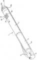
도 1은 전체 장치의 사시도.1 is a perspective view of the entire apparatus.
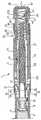
도 2는 초기 상태의 장치의 구동 기구를 도시하는 측단면도.Fig. 2 is a side sectional view showing the drive mechanism of the device in the initial state.
도 3은 장치의 투여량 설정 작동을 예시하는 측단면도.3 is a side sectional view illustrating dose setting operation of the device.
도 4는 장치의 투여량 전달을 예시하는 측단면도.4 is a side cross-sectional view illustrating dose delivery of the device.
도 5는 도 2의 확대도.5 is an enlarged view of FIG. 2;
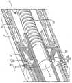
도 6은 장치의 플런져 로드, 리드 스크류, 및 플런져 로드 홀더의 도면.6 shows a plunger rod, lead screw, and plunger rod holder of the device.
도 7은 클러치 결합된 상태의 장치를 나타내는 측단면도.7 is a side cross-sectional view showing the device in a clutch engaged state;
도 8은 클러치 해제된 상태의 장치를 나타내는 측단면도.Fig. 8 is a side sectional view showing the device in a state where the clutch is released.
도 9는 다른 프리 로크를 나타내는 측단면도.9 is a side cross-sectional view showing another free lock.
장치(1)의 개요가 도 1 내지 도 2를 참조하여 설명된다.An overview of the apparatus 1 is described with reference to FIGS.
장치는 기계적 펜(pen) 타입이고:The device is of mechanical pen type:
하우징(2);A
하우징(2)의 말단부에 커플링되는 카트리지-홀더(2a);A cartridge-
카트리지의 선단부에 장착되는 피스톤(8)에 의해 밀봉되고 액체 약(4)을 담으며 카트리지-홀더(2a)에 장착되는 카트리지(3);A cartridge (3) sealed by a piston (8) mounted at the tip of the cartridge and containing a liquid medicine (4) and mounted to the cartridge-holder (2a);
장치의 말단부에 부착되는 제거가능한 캡(12);A
하우징(2)의 선단부에 조립되는 피스톤 구동 조립체(21)로 구성된다.It consists of a
피스톤 구동 조립체는 분배 중에 선단부로부터 말단부까지 작동력을 전달한다. 피스톤 구동 조립체(21)는 투여량 설정 다이얼(22), 내부 실린더(23), 프리 로크(24), 리드 스크류(25), 플런져 로드(26), 플런져 로드 홀더(27), 해제용 손잡 이(28; release knob), 투여량 표시기(또는 카운터)(29), 카운터 링(30), 나사가 형성된 인서트(31; threaded insert)로 구성된다.The piston drive assembly transmits the actuation force from the leading end to the distal end during dispensing. The
스크류 구조물들은 나사 인서트(31)와 투여량 설정 다이얼(22) 사이에(즉, "제 1 스크류 구조물"), 내부 실린더(23)와 프리 로크(24) 사이에(즉, "제 2 스크류 구조물"), 리드 스크류(25)와 플런져 로드(26) 사이에(즉, "제 3 스크류 구조물") 포함된다.The screw structures are located between the
장치의 작동을 이제 설명한다. 전달될 원하는 투여량을 설정하기 위해 사용자가 투여량 설정 다이얼(22)의 회전 손잡이(22a)를 회전시켜, 제 1 스크류 구조물(35)에 의해 투여량 설정 다이얼을 선단부를 향해 이동시킨다. 투여량 설정 중에 투여량 설정 다이얼(22)과 내부 실린더(23) 간의 상대 회전이 클러치(56)에 의해 방지되므로 내부 실린더를 허용한다.The operation of the device will now be described. To set the desired dose to be delivered, the user rotates the
내부 실린더(23)가 투여량 설정 중에 선단부를 향해 회전할 때, 리드 스크류(25)가 내부 실린더(23)의 내면에서 키 웨이(51; key way)에 위치한 한 쌍의 스플라인 가공된 돌출부(50)에 의해 플런져 로드(26)에 관해 내부 실린더(23)와 함께 회전한다. 리드 스크류(25)가 플런져 로드(26)로부터 선단부를 향해 회전할 때, 플런져 로드 홀더(27)는 플런져 로드(26)를 고정하여 플런져 로드가 선단부를 향해 변위되는 것을 방지하여 피스톤(8)과 인접한 상태를 유지한다.When the
내부 실린더(23)가 회전하면 프리 로크(24)를 제 2 스크류 구조물(44)을 통해 말단부를 향해 추가로 이동시킨다.Rotation of the
현 실시예의 설정된 투여량은 표시창(62)에 표시되는 투여량 설정 다이 얼(22)과 투여량 표시기(카운터)(29)상의 수치값(66)에 의해 표시된다.The set dose of the present embodiment is indicated by the
선택된 투여량을 환자에게 투여하기 위해, 사용자는 해제 손잡이(28)를 말단부를 향해 누르고, 투여량 설정 다이얼(22)을 내부 실린더(23)로부터 해제시켜 투여량 설정 다이얼이 내부 실린더에 대해 회전하고 말단부를 향해 이동하게 한다. 내부 실린더(23)는 축방향에서 말단부를 향해 이동하여 프리 로크(24)를 예정된 감속비로 선단 방향으로 회전시켜 내부 실린더(23)의 축방향 운동을 리드 스크류(25)로 전달하고 이를 말단부를 향해 축방향으로 이동시킨다. 그러므로, 리드 스크류(25)는 플런져 로드(26)를 말단부를 향해 민다. 결국 이는 피스톤(8)을 말단부를 향해 밀어 내용물을 카트리지(3)로부터 니들(5)을 통해 환자로 배출시킨다.To administer the selected dose to the patient, the user presses the
실시예 1의 장치의 세부사항은 도 2 내지 도 6을 참조하여 설명한다.Details of the apparatus of the first embodiment will be described with reference to FIGS. 2 to 6.
나사 인서트(31)는 당업자에게 공지된 적절한 방법에 의해 하우징(2)의 선단부(2b)의 내측에 대해 동심 관계로 조립 및 고정된다. 나사 인서트(31)는 실질적으로 원통 형상인 투여량 설정 다이얼(22)과 나사결합하여 제 1 스크류 구조물(35)을 형성한다. 투여량 설정 다이얼(22)이 장착되어 투여량 설정 중에 선단부를 향한 및 투여량 전달 중에 말단부를 향한 회전 운동을 허용한다. 바람직하게는 폴(pawl) 형상인 정지부(22d; stop)는 투여량 설정 다이얼(22)의 말단부상에 형성된다.The
하우징의 외경과 같은 직경을 갖는 원통형 회전 손잡이(22a)는 투여량 설정 다이얼(22)의 선단부에 부착된다. 톱니부(22b; serration)는 회전 손잡이(22a)의 외면상에 형성되어 사용자가 쥐기 쉽게 한다.A cylindrical
내부 실린더(23)는 회전 손잡이(22a) 내에 동심관계로 조립되고 클러치 수 단(56)에 의해 투여량 설정 다이얼(22)에 해제가능하게 연결된다. 실질적으로 원통 형성인 플랜지 부분이 내부 실린더(23)의 선단부(23a)에 형성되고 회전 손잡이(22a)의 중공 오목부(22c; hollow recess)에 삽입된다.The
프리 로크(24)의 외면은 내부 실린더(23)의 내면과 나사결합하여 제 2 스크류 구조물(44)을 형성한다. 프리 로크(24)는 자유롭게 회전하고 내부 실린더(23) 내에서 말단부와 선단부를 향해 축방향으로 이동한다.The outer surface of the
프리 로크(24)의 내면은 실질적으로 원형이 아닌 단면을 갖는 리드 스크류(25)의 선단부의 외면과 나사결합한다. 프리 로크(24)는 리드 스크류(25)의 외면상에서 자유회전하고 리드 스크류(25)의 선단부와 말단부를 향해 축방향으로 이동한다.The inner surface of the
리드 스크류(25)의 말단부는 플런져 로드(26)의 선단부와 나사결합하여 제 3 스크류 구조물(47)을 형성한다.The distal end of the
실질적으로 비-원형 단면, 바람직하게는 정사각형 튜브 형상인 플런져 로드(26)는 그 외면상에, 바람직하게는 외면의 두 개의 대향면들상에서 작은 피치(pitch)의 래칫 치형부(38; ratchet teeth)를 갖는다.The
플런져 로드 홀더(27)는 당업자에게 공지된 임의의 적절한 수단에 의해 하우징(2)의 말단부의 내측에 고정된다. 플런져 로드(26)의 외경과 같은 치수를 갖는 정사각형 통로(37)가 플런져 홀더(27)의 중심에 형성된다. 플런져 로드(26)는 정사각형 통로(37)와 결합하여 플런져 로드(26)의 회전이 플런져 로드 홀더(27)에 의해 방지된다.The
다수의 쌍, 바람직하게는 두 쌍의 가요성 래칫 치형부 암(39; arm)들이 플런져 로드 홀더(27)상에 형성된다. 이들은 장치의 래칫 기구(40)를 형성한다. 3 또는 4개의 래칫 치형부 암들이 예를 들어, 90ㅀ(예를 들어, 4개 암) 또는 120ㅀ(예를 들어, 3개 암) 등으로 오프셋되어 플런져 로드 홀더(27)상에 형성되는 다른 실시예들도 고려될 수 있다.Multiple pairs, preferably two pairs of flexible
래칫 기구(40)는 플런져 로드(26)의 래칫 치형부(38)와 결합하여 선단부를 향한 플런져 로드(26)의 축방향 운동이 방지되지만, 말단부를 향한 플런져 로드(26)의 축방향 운동은 허용된다.The
다수의, 바람직하게는 2개의 스플라인 홈(49)들이 내부 실린더(23)의 내면상에 형성된다. 다수의, 바람직하게는 2개의 스플라인 돌출부(50)들이 리드 스크류(25)의 선단부의 외면에 형성된다. 스플라인 돌출부(50)는 내부 실린더(23)의 스플라인 홈(49)들과 결합하여 내부 실린더(23)에 대한 선단부 및 말단부를 향한 리드 스크류(25)의 축방향 운동을 허용한다. 스플라인 홈(49)들과 스플라인 돌출부(50)들은 스플라인 구조물(51)을 함께 형성한다.Multiple, preferably two
실질적으로 원통 형상인 해제 손잡이(28)가 말단부에서 개방되고 선단부에서 밀폐되고, 회전 손잡이(22a)의 내부 측면상에서 중공부(22c)에서 동심관계로 조립된다. 환형 리브(53; annular rib)가 해제 손잡이(28)의 외주(outer circumference)상에 형성되고 회전 손잡이(22a)의 내주상에서 환형 홈(52)과 결합한다. 그러므로, 해제 손잡이(28)는 회전 손잡이(22a)에 대해 선단부 및 말단부를 향해 축방향으로 이동 및 자유 회전한다. 선단부 및 말단부를 향한 해제 손잡 이(28)의 운동은 환형 홈(52)의 폭에 의해 제한된다.A substantially
해제 손잡이(28)는 내부 실린더(23)의 플랜지 부분(23b)과 인접하게 되거나 멀어질 수 있도록 이동한다.The release handle 28 moves so as to be adjacent to or away from the
예를 들어, 치형부 등과 같은 파(wave)형 환형부(54)가 내부 실린더(23)의 플랜지 부분(23b)의 말단부 면상에 형성되고 투여량 설정 다이얼(22)상의 상응하는 파형 견부(55; shoulder)와 결합한다. 파형 환형부(54)와 파형 견부(55)는 내부 실린더(23)와 투여량 설정 다이얼(22)을 해제가능하게 연결하는 제 1 클러치를 함께 형성하여 투여량 설정 중에 상대회전 운동이 방지된다.For example, a wave annular portion 54 such as a tooth or the like is formed on the distal face of the
제 2 클러치(60)가 해제 손잡이(28)의 내면과 내부 실린더(23)의 선단부 사이에 형성된다. 제 2 클러치(60)는 내부 실린더(23)와 해제 손잡이(28)상에 위치하는 2개의 보조 파형 형상부(configuration), 치형 형상부 등으로 구상된다.A
본 실시예에서, 설정된 투여량은 투여량 설정 다이얼(22)과 카운터 링(30)상의 수치값으로서 표시된다. 설정된 투여량은 하우징(2)의 선단부에 위치한 표시창(62)을 통해 보인다. 본 실시예의 표시창(62)은 개방되었지만, 기구에 오염물, 먼지, 액체 등이 들어가는 것을 방지하거나 및/또는 확대경으로서 작용하도록 투명 렌즈가 표시창(62)을 커버하도록 사용될 수 있다.In this embodiment, the set dose is displayed as a numerical value on the
카운터 링(30)은 말단부로부터 선단부까지 투여량 설정 다이얼(22)의 외주상에 형성되는 다수의 리브 홈(64; rib groove)들과, 카운터 링(30)의 내면상에 형성되는 상응하는 개수의 리브(63)에 의해 투여량 설정 다이얼(22)과 결합한다. 카운터 링(30)은 투여량 설정 다이얼(22)의 선단부 및 말단부 모두를 향해 축방향에서 이동할 수 있다. 투여량 설정 다이얼(22)에 대한 카운터 링(30)의 축방향 이동을 방지하기 위해, 위치결정용 칼라(65; collar)가 투여량 설정 다이얼(22)의 외주상에 조립되고 카운터 링(30)의 선단부에 인접한 하우징(2)의 내면에 고정된다. 하우징(2)에 합체되는 원통형 위치결정용 칼라(65)는 카운터 링(30)의 말단부에 인접한다. 그러므로, 카운터 링(30)은 투여량 설정 및 투여량 전달 중에 하우징에 대해 투여량 설정 다이얼(22)과 함께 회전할 수 있지만, 하우징(2)에 대해 축방향 이동하는 것이 방지된다.The
본 실시예에서, 카운터 링(30)은 "0" 내지 "9"의 설정 투여량에 대한 "단위(unit)" 값을 표시한다. "수십(tens)"의 값들은 카운터 링(30)의 완전한 회전 중에 상응하는 "수십"의 값이 연속적으로 표시되도록 투여량 설정 다이얼(22)상에 표시된다.In this embodiment, the
본 발명에 따른 장치의 3개의 스크류 구조물들(즉, 35, 44, 47) 모두 상이한 스크류 피치를 갖는다. 제 1 (35), 제 2 (44), 제 3 스크류 구조물(47) 간의 스크류 피치들의 비는 스크류 구조물들의 전달력들의 효율적인 감소("속도 감소")를 달성하기 위해 약 3:2:1이다.All three screw structures (
장치(1)의 실시예 2가 도 7 및 도 8을 참조하여 설명된다. 본 실시예 2는 투여량 설정 다이얼(22)과 내부 실린더(23) 사이의 제 1 클러치(56)에 대한 수정사항을 포함한다.
도 7은 내부 실린더(23)의 선단부에 위치한 다른 클러치(57)를 나타낸다. 클러치(57)는 원추형 캠 면(57a)들과 다수의 등간격 이격된 제 1 결합부(54a)들로 구 성된다. 말단부를 향하는 또는 선단부를 향하는 해제용 손잡이(28)의 축방향 운동을 통해, 클러치(57)는 압축 또는 확장되어 제 1 결합 부분(54a)들이 회전 손잡이(22a)의 내면상에 형성된 상응하는 제 2 결합 부분(54b)들과 결합하거나 해제되게 할 수 있다. 제 1 결합 부분(54a)들과 제 2 결합 부분(54b)들은 예를 들어, 한 쌍의 스프링 작용 부분(도시않음)의 스프링 힘에 의해 결합된다.7 shows another clutch 57 located at the tip of the
투여량 설정 중에, 제 1 결합 부분(54a)들과 제 2 결합 부분(54b)들은 스프링 힘 하에 결합되어 내부 실린더(23)와 투여량 설정 다이얼(22)이 커플링되고 내부 실린더(23)와 투여량 설정 다이얼(22) 간의 상대회전이 방지된다.During dose setting, the
투여량 분배 중에, 해제용 손잡이(28)가 말단 방향으로 밀려 제 1 결합 부분(54a)들을 제 2 결합 부분(54b)들로부터 해제시켜 투여량 설정 다이얼(22)을 내부 실린더(23)로부터 분리시켜 투여량 설정 다이얼(22)이 내부 실린더(23)에 대해 회전할 수 있게 한다.During dose dispensing, the
본 발명의 기구 및 장치는 상술한 실시예 1 및 실시예 2에 한정되지 않고 본 발명의 기술적 아이디어에 근거한 다양하고 효과적인 대안들이 가능하다. 예를 들어, 도 9는 다른 해결방안을 도시하며, 여기서 프리 로크는 플런져 로드 홀더에 고정된다. 이 경우, 제 1, 제 2, 제 3 스크류 구조물들 간의 스크류 피치 비들은 약 3:3:1이다.The apparatus and apparatus of the present invention are not limited to the above-described
Claims (9)
Translated fromKoreanApplications Claiming Priority (3)
| Application Number | Priority Date | Filing Date | Title |
|---|---|---|---|
| EP04023630.9 | 2004-10-04 | ||
| EP04023630 | 2004-10-04 | ||
| PCT/EP2005/009839WO2006037434A1 (en) | 2004-10-04 | 2005-09-14 | Drive mechanism for a drug delivery device |
Publications (2)
| Publication Number | Publication Date |
|---|---|
| KR20070107657Atrue KR20070107657A (en) | 2007-11-07 |
| KR101374572B1 KR101374572B1 (en) | 2014-03-17 |
Family
ID=34926840
Family Applications (1)
| Application Number | Title | Priority Date | Filing Date |
|---|---|---|---|
| KR1020077007620AExpired - LifetimeKR101374572B1 (en) | 2004-10-04 | 2005-09-14 | Drive mechanism for a drug delivery device |
Country Status (27)
| Country | Link |
|---|---|
| US (9) | US20070244436A1 (en) |
| EP (1) | EP1799287B1 (en) |
| JP (1) | JP4922172B2 (en) |
| KR (1) | KR101374572B1 (en) |
| CN (1) | CN100569308C (en) |
| AU (1) | AU2005291585B2 (en) |
| BR (1) | BRPI0516441B8 (en) |
| CA (1) | CA2582976C (en) |
| CR (1) | CR8989A (en) |
| CY (1) | CY1114375T1 (en) |
| DK (1) | DK1799287T3 (en) |
| EC (1) | ECSP077369A (en) |
| EG (1) | EG25844A (en) |
| ES (1) | ES2427146T3 (en) |
| IL (1) | IL182073A (en) |
| MA (1) | MA28913B1 (en) |
| MX (1) | MX2007003682A (en) |
| NO (1) | NO338276B1 (en) |
| NZ (1) | NZ554384A (en) |
| PL (1) | PL1799287T3 (en) |
| PT (1) | PT1799287E (en) |
| RU (1) | RU2387461C2 (en) |
| SI (1) | SI1799287T1 (en) |
| TN (1) | TNSN07123A1 (en) |
| UA (1) | UA87334C2 (en) |
| WO (1) | WO2006037434A1 (en) |
| ZA (1) | ZA200702032B (en) |
Cited By (1)
| Publication number | Priority date | Publication date | Assignee | Title |
|---|---|---|---|---|
| KR101521612B1 (en)* | 2010-11-19 | 2015-05-19 | 일라이 릴리 앤드 캄파니 | Needle magazine for medication injection device |
Families Citing this family (132)
| Publication number | Priority date | Publication date | Assignee | Title |
|---|---|---|---|---|
| US6663602B2 (en) | 2000-06-16 | 2003-12-16 | Novo Nordisk A/S | Injection device |
| WO2003068290A2 (en) | 2002-02-11 | 2003-08-21 | Antares Pharma, Inc. | Intradermal injector |
| GB0304822D0 (en) | 2003-03-03 | 2003-04-09 | Dca Internat Ltd | Improvements in and relating to a pen-type injector |
| EP1789128B1 (en) | 2004-08-27 | 2018-05-09 | STOCO 10 GmbH | Electronically and remotely controlled pill and system for delivering at least one medicament |
| EP1642607A1 (en) | 2004-10-04 | 2006-04-05 | Sanofi-Aventis Deutschland GmbH | Dose display mechanism for a drug delivery device |
| MX2007003682A (en) | 2004-10-04 | 2007-08-07 | Sanofi Aventis Deutschland | Drive mechanism for a drug delivery device. |
| ATE444090T1 (en) | 2004-10-21 | 2009-10-15 | Novo Nordisk As | SELECTION MECHANISM FOR A ROTARY PIN |
| JP4903160B2 (en)* | 2005-01-18 | 2012-03-28 | ウォックハート アメリカズ インコーポレイテッド | Pen-type drug injection device |
| HUE042286T2 (en) | 2005-01-24 | 2019-06-28 | Antares Pharma Inc | Needle-filled pre-filled syringe |
| DE102005008280B3 (en)* | 2005-02-23 | 2006-07-13 | Tecpharma Licensing Ag | Medicine administering device has medicine transporting elements and a dosing device that is used with a display drum and an activation element to permit the accurate administration of correct medicine amounts |
| WO2007131013A1 (en) | 2006-05-03 | 2007-11-15 | Antares Pharma, Inc. | Two-stage reconstituting injector |
| WO2007131025A1 (en) | 2006-05-03 | 2007-11-15 | Antares Pharma, Inc. | Injector with adjustable dosing |
| JP5253387B2 (en)* | 2006-05-18 | 2013-07-31 | ノボ・ノルデイスク・エー/エス | Injection device with mode locking means |
| DE102007018696A1 (en)* | 2007-04-18 | 2008-10-23 | Sanofi-Aventis Deutschland Gmbh | Injection device for dispensing a medicament |
| DE102007026083A1 (en)* | 2007-05-25 | 2008-11-27 | Haselmeier S.A.R.L. | injection device |
| US10420880B2 (en) | 2007-10-02 | 2019-09-24 | West Pharma. Services IL, Ltd. | Key for securing components of a drug delivery system during assembly and/or transport and methods of using same |
| US7967795B1 (en) | 2010-01-19 | 2011-06-28 | Lamodel Ltd. | Cartridge interface assembly with driving plunger |
| US9656019B2 (en) | 2007-10-02 | 2017-05-23 | Medimop Medical Projects Ltd. | Apparatuses for securing components of a drug delivery system during transport and methods of using same |
| US9345836B2 (en) | 2007-10-02 | 2016-05-24 | Medimop Medical Projects Ltd. | Disengagement resistant telescoping assembly and unidirectional method of assembly for such |
| BRPI0817907B8 (en) | 2007-10-02 | 2021-06-22 | Lamodel Ltd | apparatus for administering a substance to an individual |
| DE102007054020A1 (en)* | 2007-11-13 | 2009-05-14 | Tecpharma Licensing Ag | Injection device with uncoupling click mechanism |
| JP5451641B2 (en)* | 2008-02-07 | 2014-03-26 | ノボ・ノルデイスク・エー/エス | Injection device with mode defining element |
| EP3636301A1 (en) | 2008-03-10 | 2020-04-15 | Antares Pharma, Inc. | Injector safety device |
| CN102065930B (en) | 2008-06-19 | 2013-05-22 | 皇家飞利浦电子股份有限公司 | Device for delivery of powder like medication in a humid environment |
| DE102008030631A1 (en)* | 2008-06-24 | 2009-12-31 | Würth Elektronik iBE GmbH | Electronic component |
| US8376993B2 (en) | 2008-08-05 | 2013-02-19 | Antares Pharma, Inc. | Multiple dosage injector |
| US9393369B2 (en) | 2008-09-15 | 2016-07-19 | Medimop Medical Projects Ltd. | Stabilized pen injector |
| US12097357B2 (en) | 2008-09-15 | 2024-09-24 | West Pharma. Services IL, Ltd. | Stabilized pen injector |
| US8152779B2 (en) | 2008-12-30 | 2012-04-10 | Medimop Medical Projects Ltd. | Needle assembly for drug pump |
| EP2208503A1 (en)* | 2009-01-20 | 2010-07-21 | Sanofi-Aventis Deutschland GmbH | Drive assembly and medication delivery device |
| CA2753138C (en) | 2009-02-27 | 2017-11-14 | Lifescan, Inc. | Medical module for drug delivery pen |
| US8257319B2 (en)* | 2009-06-01 | 2012-09-04 | Sanofi-Aventis Deutschland Gmbh | Drug delivery device inner housing having helical spline |
| TWI530306B (en) | 2009-06-02 | 2016-04-21 | 賽諾菲阿凡提斯德意志有限公司 | Drug delivery device assembly and drug delivery device |
| WO2010140974A1 (en)* | 2009-06-05 | 2010-12-09 | Shl Group Ab | Medicament delivery device |
| EP2266647A1 (en)* | 2009-06-25 | 2010-12-29 | Sanofi-Aventis Deutschland GmbH | Drive mechanism for drug delivery device |
| PL214940B1 (en) | 2009-07-31 | 2013-09-30 | Lozano Platonoff Alberto | Indication mechanism of an automatic applicator, especially for insulin |
| US8157769B2 (en) | 2009-09-15 | 2012-04-17 | Medimop Medical Projects Ltd. | Cartridge insertion assembly for drug delivery system |
| US10071196B2 (en) | 2012-05-15 | 2018-09-11 | West Pharma. Services IL, Ltd. | Method for selectively powering a battery-operated drug-delivery device and device therefor |
| US10071198B2 (en) | 2012-11-02 | 2018-09-11 | West Pharma. Servicees IL, Ltd. | Adhesive structure for medical device |
| CA2772984A1 (en) | 2009-09-30 | 2011-04-07 | Sanofi-Aventis Deutschland Gmbh | Drug delivery device, assembly for a drug delivery device and method for setting up a drug delivery device |
| DK2482899T3 (en)* | 2009-09-30 | 2014-01-06 | Sanofi Aventis Deutschland | CONSTRUCTION FOR THE ADMINISTRATION FOR THE ADMINISTRATION OF MEDICINE |
| GB0918145D0 (en) | 2009-10-16 | 2009-12-02 | Owen Mumford Ltd | Injector apparatus |
| PL215310B1 (en) | 2009-10-30 | 2013-11-29 | Kappa Medilab Spolka Z Ograniczona Odpowiedzialnoscia | Automatic applicator, especially for insulin |
| EP2496290B1 (en) | 2009-11-03 | 2017-01-04 | Sanofi-Aventis Deutschland GmbH | Assembly for a drug delivery device and drug delivery device |
| EP3192548B1 (en)* | 2009-12-07 | 2021-01-27 | Sanofi-Aventis Deutschland GmbH | Drive assembly for a drug delivery device and drug delivery device |
| ES2700359T3 (en) | 2009-12-17 | 2019-02-15 | Sanofi Aventis Deutschland | Medical device and method of assembly |
| US8348898B2 (en) | 2010-01-19 | 2013-01-08 | Medimop Medical Projects Ltd. | Automatic needle for drug pump |
| EP2569031B1 (en) | 2010-05-10 | 2017-10-11 | Medimop Medical Projects Ltd. | Low volume accurate injector |
| CA2806983A1 (en)* | 2010-08-06 | 2012-02-09 | Sanofi-Aventis Deutschland Gmbh | Assembly for a drug delivery device, piston rod and drug delivery device |
| EP2452712A1 (en)* | 2010-11-12 | 2012-05-16 | Sanofi-Aventis Deutschland GmbH | Drive mechanism for a drug delivery device and drug delivery device |
| US8535268B2 (en) | 2010-12-22 | 2013-09-17 | Alcon Research, Ltd. | Device for at least one of injection or aspiration |
| EP3878495B1 (en)* | 2011-03-16 | 2024-06-12 | Becton, Dickinson and Company | Multiple use disposable injection pen |
| US12350474B2 (en) | 2011-03-16 | 2025-07-08 | Becton, Dickinson And Company | Multiple use disposable injection pen |
| US11577029B2 (en) | 2012-03-15 | 2023-02-14 | Becton, Dickinson And Company | Multiple use disposable injection pen |
| JP2014513594A (en) | 2011-03-17 | 2014-06-05 | サノフィ−アベンティス・ドイチュラント・ゲゼルシャフト・ミット・ベシュレンクテル・ハフツング | Drug delivery device and method of assembling the same |
| USD702834S1 (en) | 2011-03-22 | 2014-04-15 | Medimop Medical Projects Ltd. | Cartridge for use in injection device |
| MY160872A (en)* | 2011-03-25 | 2017-03-31 | Sanofi Aventis Deutschland | Dose setting mechanism and injection device |
| CA2830022C (en)* | 2011-03-25 | 2019-02-19 | Sanofi-Aventis Deutschland Gmbh | Dose setting mechanism and injection device |
| US9220660B2 (en) | 2011-07-15 | 2015-12-29 | Antares Pharma, Inc. | Liquid-transfer adapter beveled spike |
| US8496619B2 (en) | 2011-07-15 | 2013-07-30 | Antares Pharma, Inc. | Injection device with cammed ram assembly |
| JP6072453B2 (en)* | 2011-07-25 | 2017-02-01 | 株式会社大協精工 | Plunger kit for pharmaceutical syringe |
| RU2620351C2 (en) | 2011-09-22 | 2017-05-24 | Эббви Инк. | Automated injector |
| CA2849806A1 (en) | 2011-09-22 | 2013-03-28 | Abbvie Inc. | Automatic injection device |
| US8784388B2 (en) | 2011-09-30 | 2014-07-22 | Becton, Dickinson And Company | Syringe with disinfecting tip feature |
| KR101870065B1 (en)* | 2011-10-17 | 2018-06-21 | 에스에이치엘 그룹 에이비 | Medicament delivery device |
| CN102327656B (en)* | 2011-10-18 | 2013-05-08 | 清华大学 | Disposable array miniature injection needle head |
| JP6069351B2 (en) | 2011-12-29 | 2017-02-01 | ノボ・ノルデイスク・エー/エス | Torsion spring type automatic syringe with dial-up / dial-down administration mechanism |
| US9486583B2 (en) | 2012-03-06 | 2016-11-08 | Antares Pharma, Inc. | Prefilled syringe with breakaway force feature |
| IN2014DN07773A (en)* | 2012-03-15 | 2015-05-15 | Becton Dickinson Co | |
| US9072827B2 (en) | 2012-03-26 | 2015-07-07 | Medimop Medical Projects Ltd. | Fail safe point protector for needle safety flap |
| BR112014024651B1 (en)* | 2012-04-05 | 2021-09-21 | Sanofi-Aventis Deutschland Gmbh | PEN TYPE INJECTOR |
| EP4186545A1 (en) | 2012-04-06 | 2023-05-31 | Antares Pharma, Inc. | Needle assisted jet injection administration of testosterone compositions |
| US9364610B2 (en) | 2012-05-07 | 2016-06-14 | Antares Pharma, Inc. | Injection device with cammed ram assembly |
| CN102716529B (en)* | 2012-06-29 | 2014-02-19 | 北京甘甘科技有限公司 | Pen injector |
| JP6240183B2 (en)* | 2012-06-29 | 2017-11-29 | ノボ・ノルデイスク・エー/エス | Shield lock for spring driven injection device |
| JP6022255B2 (en)* | 2012-07-20 | 2016-11-09 | Jcrファーマ株式会社 | Injection device |
| US9421323B2 (en) | 2013-01-03 | 2016-08-23 | Medimop Medical Projects Ltd. | Door and doorstop for portable one use drug delivery apparatus |
| KR102244475B1 (en) | 2013-01-08 | 2021-04-23 | 쓰리엠 이노베이티브 프로퍼티즈 컴파니 | Applicator for applying a microneedle device to skin |
| DK3308815T3 (en) | 2013-01-15 | 2021-01-18 | Sanofi Aventis Deutschland | PENTYPE MEDICINE INJECTION DEVICE WITH ABSOLUTELY ANGLE DOSAGE ENCODER MECHANISM |
| FI3659647T3 (en) | 2013-02-11 | 2024-03-28 | Antares Pharma Inc | NEEDLE-ASSISTED SPRAY INJECTOR WITH REDUCED TRIGGER FORCE |
| CA2905031C (en) | 2013-03-11 | 2018-01-23 | Hans PFLAUMER | Dosage injector with pinion system |
| EP2983763B1 (en)* | 2013-04-10 | 2017-05-24 | Sanofi | Drive mechanism for a drug delivery device |
| US9011164B2 (en) | 2013-04-30 | 2015-04-21 | Medimop Medical Projects Ltd. | Clip contact for easy installation of printed circuit board PCB |
| CN104338210B (en)* | 2013-07-30 | 2017-04-12 | 广东东阳光药业有限公司 | Injection device |
| CA2922441C (en)* | 2013-08-29 | 2018-07-17 | Carebay Europe Ltd | Medicament delivery device |
| AR102193A1 (en)* | 2014-10-09 | 2017-02-08 | Sanofi Sa | DRIVING HOSE, DRUG ADMINISTRATION DEVICE AND METHOD FOR ASSEMBLY OF A DRUG ADMINISTRATION DEVICE |
| CA3009221A1 (en) | 2014-12-23 | 2016-06-30 | Automed Pty Ltd | Delivery apparatus, system and associated methods |
| US10293120B2 (en) | 2015-04-10 | 2019-05-21 | West Pharma. Services IL, Ltd. | Redundant injection device status indication |
| US10149943B2 (en) | 2015-05-29 | 2018-12-11 | West Pharma. Services IL, Ltd. | Linear rotation stabilizer for a telescoping syringe stopper driverdriving assembly |
| CN113181477B (en) | 2015-06-04 | 2023-07-14 | 麦迪麦珀医疗工程有限公司 | Cartridge insertion for drug delivery device |
| CH711240A2 (en)* | 2015-06-23 | 2016-12-30 | Tecpharma Licensing Ag | Auto injection device. |
| US9987432B2 (en) | 2015-09-22 | 2018-06-05 | West Pharma. Services IL, Ltd. | Rotation resistant friction adapter for plunger driver of drug delivery device |
| US10576207B2 (en) | 2015-10-09 | 2020-03-03 | West Pharma. Services IL, Ltd. | Angled syringe patch injector |
| US10086145B2 (en) | 2015-09-22 | 2018-10-02 | West Pharma Services Il, Ltd. | Rotation resistant friction adapter for plunger driver of drug delivery device |
| EP3147034A1 (en)* | 2015-09-25 | 2017-03-29 | Sulzer Mixpac AG | Applicator for ejecting doses of a flowable component |
| US11318254B2 (en) | 2015-10-09 | 2022-05-03 | West Pharma. Services IL, Ltd. | Injector needle cap remover |
| PL414383A1 (en) | 2015-10-15 | 2017-04-24 | Copernicus Spółka Z Ograniczoną Odpowiedzialnością | Setting mechanism, in particular for dosing pharmaceuticals |
| PL414382A1 (en) | 2015-10-15 | 2017-04-24 | Copernicus Spółka Z Ograniczoną Odpowiedzialnością | Setting mechanism, in particular for dosing |
| PL227678B1 (en)* | 2015-12-22 | 2018-01-31 | Copernicus Spolka Z Ograniczona Odpowiedzialnoscia | Control and drive system for the device intended for injection and the device for making injections equipped with such a system |
| JP6885960B2 (en) | 2016-01-21 | 2021-06-16 | ウェスト ファーマ サービシーズ イスラエル リミテッド | Drug delivery device with visual indicators |
| US10646643B2 (en) | 2016-01-21 | 2020-05-12 | West Pharma. Services IL, Ltd. | Needle insertion and retraction mechanism |
| EP3711793B1 (en) | 2016-01-21 | 2021-12-01 | West Pharma Services IL, Ltd. | A method of connecting a cartridge to an automatic injector |
| EP3210640A1 (en)* | 2016-02-24 | 2017-08-30 | Sima Patent ve Lisanslama Hizmetleri Ltd.Sti. | Drug delivery device for liquid pharmaceuticals |
| WO2017160882A1 (en)* | 2016-03-14 | 2017-09-21 | Ayasdi, Inc. | Grouping of data points in data analysis for graph generation |
| WO2017158033A1 (en)* | 2016-03-15 | 2017-09-21 | Sanofi | Dosing mechanism for multi-shot injection device comprising flexible ratchet element |
| US11389597B2 (en) | 2016-03-16 | 2022-07-19 | West Pharma. Services IL, Ltd. | Staged telescopic screw assembly having different visual indicators |
| US10376647B2 (en) | 2016-03-18 | 2019-08-13 | West Pharma. Services IL, Ltd. | Anti-rotation mechanism for telescopic screw assembly |
| USD818587S1 (en)* | 2016-03-29 | 2018-05-22 | Abbevie Inc. | Automatic injection device |
| EP3463514B1 (en)* | 2016-05-30 | 2024-01-10 | Novo Nordisk A/S | Drug delivery device with zero position adjustment feature |
| EP3463520B1 (en) | 2016-05-30 | 2024-01-24 | Novo Nordisk A/S | Mounting feature for accessory device |
| CN109310831B (en) | 2016-06-02 | 2021-11-23 | 西医药服务以色列有限公司 | Three position needle retraction |
| US11338090B2 (en) | 2016-08-01 | 2022-05-24 | West Pharma. Services IL, Ltd. | Anti-rotation cartridge pin |
| JP7059251B2 (en) | 2016-08-01 | 2022-04-25 | ウェスト ファーマ サービシーズ イスラエル リミテッド | A spring that prevents the door from closing halfway |
| US11172701B2 (en)* | 2017-01-11 | 2021-11-16 | Banana Bros, Llc | System utilizing compressed smokable product |
| JP6412963B2 (en)* | 2017-01-20 | 2018-10-24 | ベクトン・ディキンソン・アンド・カンパニーBecton, Dickinson And Company | Multi-use disposable injection pen |
| US10329075B2 (en)* | 2017-05-12 | 2019-06-25 | Jetty Marketing, Llc. | Dispenser for viscous cannabis fluids and means thereof |
| EP3630226A1 (en) | 2017-05-30 | 2020-04-08 | West Pharma. Services Il, Ltd. | Modular drive train for wearable injector |
| USD860435S1 (en) | 2017-09-13 | 2019-09-17 | Janssen Pharmaceutica Nv | Intranasal drug delivery device |
| US20200009081A1 (en) | 2017-09-13 | 2020-01-09 | Janssen Pharmaceutica N.V. | Delivery Of Esketamine For The Treatment Of Depression |
| EP3694584A1 (en)* | 2017-10-10 | 2020-08-19 | Novo Nordisk A/S | Prefilled drug delivery device with reduced air gap |
| JP7402799B2 (en) | 2017-12-22 | 2023-12-21 | ウェスト ファーマ サービシーズ イスラエル リミテッド | Syringes available with different cartridge sizes |
| RU2729432C1 (en)* | 2019-10-23 | 2020-08-06 | Общество с ограниченной ответственностью «НЭКСТ БИО» | Device for drug delivery |
| GB2590494A (en)* | 2019-12-20 | 2021-06-30 | Maguire Kevin | A dispensing device |
| RU2733692C1 (en)* | 2020-01-24 | 2020-10-06 | Александр Александрович Петров | Syringe pen |
| US11957542B2 (en) | 2020-04-30 | 2024-04-16 | Automed Patent Holdco, Llc | Sensing complete injection for animal injection device |
| USD1086441S1 (en) | 2020-09-02 | 2025-07-29 | Janssen Pharmaceutica Nv | Intranasal drug delivery device |
| CN113413515B (en)* | 2021-07-13 | 2022-08-26 | 曲靖市妇幼保健院 | Painless injection system of paediatrics |
| US12338059B2 (en) | 2021-08-13 | 2025-06-24 | Jetty Marketing, LLC | Apparatus, system and method comprising a dispenser with a modular cartridge for the dispensing of cannabis extract |
| US20230108994A1 (en)* | 2021-10-04 | 2023-04-06 | Robert Peliks | Syringe and Method of Use |
| PE20242083A1 (en)* | 2021-11-15 | 2024-10-18 | Llc Next Bio | DEVICE FOR ADMINISTERING MEDICATIONS |
| IT202100030476A1 (en) | 2021-12-02 | 2022-03-02 | Francesco Dadone | HANDLING SYSTEM OF A STRETCHER SUPPORT BASE |
| EP4623962A1 (en)* | 2024-03-28 | 2025-10-01 | Ypsomed AG | Injection device for administering a fluid product and method for assembling said device |
Family Cites Families (68)
| Publication number | Priority date | Publication date | Assignee | Title |
|---|---|---|---|---|
| US533575A (en) | 1895-02-05 | wilkens | ||
| US3481022A (en)* | 1965-09-21 | 1969-12-02 | Robert Neuschotz | Tool for installing threaded parts,and related methods |
| US3891127A (en)* | 1973-12-04 | 1975-06-24 | Alberto Fernandez | Material applying dispenser having screw actuated feed |
| IE52621B1 (en)* | 1981-02-12 | 1988-01-06 | Turner Robert Charles | Dose metering plunger devices for use with syringes |
| DE3715258C2 (en) | 1987-05-08 | 1996-10-31 | Haselmeier Wilhelm Fa | Injection device |
| GB8713810D0 (en) | 1987-06-12 | 1987-07-15 | Hypoguard Uk Ltd | Measured dose dispensing device |
| US5226895A (en)* | 1989-06-05 | 1993-07-13 | Eli Lilly And Company | Multiple dose injection pen |
| GB9007113D0 (en)* | 1990-03-29 | 1990-05-30 | Sams Bernard | Dispensing device |
| US5226896A (en) | 1990-04-04 | 1993-07-13 | Eli Lilly And Company | Dose indicating injection pen |
| AU641206B2 (en) | 1991-01-22 | 1993-09-16 | Eli Lilly And Company | Multiple dose injection pen |
| DK0525525T3 (en) | 1991-07-24 | 1995-10-02 | Medico Dev Investment Co | Injector |
| DK175491D0 (en)* | 1991-10-18 | 1991-10-18 | Novo Nordisk As | APPARATUS |
| JPH05161713A (en)* | 1991-12-12 | 1993-06-29 | Terumo Corp | Medicine quantitative dosing device |
| US5279585A (en)* | 1992-02-04 | 1994-01-18 | Becton, Dickinson And Company | Medication delivery pen having improved dose delivery features |
| US5271527A (en) | 1992-04-02 | 1993-12-21 | Habley Medical Technology Corporation | Reusable pharmaceutical dispenser with full stroke indicator |
| US5300041A (en) | 1992-06-01 | 1994-04-05 | Habley Medical Technology Corporation | Dose setting and repeating syringe |
| US5545147A (en)* | 1992-10-20 | 1996-08-13 | Eli Lilly And Company | Anti-backup improvement for hypodermic syringes |
| US5391157A (en) | 1992-10-20 | 1995-02-21 | Eli Lilly And Company | End of dose indicator |
| US5378233A (en) | 1992-11-18 | 1995-01-03 | Habley Medical Technology Corporation | Selected dose pharmaceutical dispenser |
| US5320609A (en) | 1992-12-07 | 1994-06-14 | Habley Medical Technology Corporation | Automatic pharmaceutical dispensing syringe |
| FR2701211B1 (en) | 1993-02-08 | 1995-05-24 | Aguettant Lab | DOSING INSTRUMENT, ESPECIALLY INJECTION |
| US5383865A (en) | 1993-03-15 | 1995-01-24 | Eli Lilly And Company | Medication dispensing device |
| ZA941881B (en) | 1993-04-02 | 1995-09-18 | Lilly Co Eli | Manifold medication injection apparatus and method |
| ATE225197T1 (en)* | 1994-05-30 | 2002-10-15 | B D Medico S A R L | INJECTION DEVICE |
| US5582598A (en) | 1994-09-19 | 1996-12-10 | Becton Dickinson And Company | Medication delivery pen with variable increment dose scale |
| JP3568959B2 (en)* | 1995-03-07 | 2004-09-22 | イーライ・リリー・アンド・カンパニー | Reusable dosing device |
| AU1860697A (en)* | 1995-09-08 | 1997-07-28 | Visionary Medical Products Corporation | Pen-type injector drive mechanism |
| US5688251A (en)* | 1995-09-19 | 1997-11-18 | Becton Dickinson And Company | Cartridge loading and priming mechanism for a pen injector |
| US5674204A (en) | 1995-09-19 | 1997-10-07 | Becton Dickinson And Company | Medication delivery pen cap actuated dose delivery clutch |
| UA49912C2 (en) | 1996-09-13 | 2002-10-15 | Ново Нордіск А/С | Device for dose indication in injection syringe |
| US5851079A (en) | 1996-10-25 | 1998-12-22 | The Procter & Gamble Company | Simplified undirectional twist-up dispensing device with incremental dosing |
| DE19730999C1 (en) | 1997-07-18 | 1998-12-10 | Disetronic Licensing Ag | Injection pen dosing selected volume of fluid, especially insulin |
| US5921966A (en) | 1997-08-11 | 1999-07-13 | Becton Dickinson And Company | Medication delivery pen having an improved clutch assembly |
| CZ297361B6 (en) | 1998-01-30 | 2006-11-15 | Novo Nordisk A/S | Injection syringe |
| US5961495A (en) | 1998-02-20 | 1999-10-05 | Becton, Dickinson And Company | Medication delivery pen having a priming mechanism |
| US6221053B1 (en) | 1998-02-20 | 2001-04-24 | Becton, Dickinson And Company | Multi-featured medication delivery pen |
| US6248095B1 (en) | 1998-02-23 | 2001-06-19 | Becton, Dickinson And Company | Low-cost medication delivery pen |
| US6187233B1 (en) | 1998-12-15 | 2001-02-13 | Guardian Automotive Trim, Inc. | Automotive trim with clear top coat and method of making same |
| DE19900827C1 (en) | 1999-01-12 | 2000-08-17 | Disetronic Licensing Ag | Device for the dosed administration of an injectable product |
| DE19900792C1 (en)* | 1999-01-12 | 2000-06-15 | Disetronic Licensing Ag | Injection unit forming part of e.g. pen-type self-injection syringe has continuous dosing stop in spiral form with constant pitch ensuring close fine control and accuracy in use |
| DE29900482U1 (en) | 1999-01-14 | 2000-08-31 | Medico Development Investment Co., Ascona | Injection device |
| SE9901366D0 (en) | 1999-04-16 | 1999-04-16 | Pharmacia & Upjohn Ab | Injector device and method for its operation |
| AU6892100A (en) | 1999-08-05 | 2001-03-05 | Becton Dickinson & Company | Medication delivery pen |
| GB0007071D0 (en) | 2000-03-24 | 2000-05-17 | Sams Bernard | One-way clutch mechanisms and injector devices |
| US6547763B2 (en) | 2000-05-18 | 2003-04-15 | Novo Nordisk A/S | Dose display for injection device |
| US6663602B2 (en) | 2000-06-16 | 2003-12-16 | Novo Nordisk A/S | Injection device |
| CN1268405C (en) | 2000-10-09 | 2006-08-09 | 伊莱利利公司 | Pen device for administration of parathyroid hormone |
| US6899699B2 (en) | 2001-01-05 | 2005-05-31 | Novo Nordisk A/S | Automatic injection device with reset feature |
| US6676692B2 (en) | 2001-04-27 | 2004-01-13 | Intek Technology L.L.C. | Apparatus for delivering, repositioning and/or retrieving self-expanding stents |
| ES2365807T3 (en) | 2001-05-16 | 2011-10-11 | ELI LILLY & COMPANY | MEDICATION INJECTOR DEVICE WITH MOTOR ASSEMBLY THAT FACILITATES REARME. |
| JP4350525B2 (en) | 2002-03-18 | 2009-10-21 | イーライ リリー アンド カンパニー | Drug dispensing device with gear set giving mechanical advantages |
| EP1545663B1 (en) | 2002-10-01 | 2006-08-30 | Becton Dickinson and Company | Medication delivery pen |
| GB0304823D0 (en) | 2003-03-03 | 2003-04-09 | Dca Internat Ltd | Improvements in and relating to a pen-type injector |
| GB0304824D0 (en)* | 2003-03-03 | 2003-04-09 | Dca Internat Ltd | Improvements in and relating to a pen-type injector |
| GB0304822D0 (en) | 2003-03-03 | 2003-04-09 | Dca Internat Ltd | Improvements in and relating to a pen-type injector |
| US6932794B2 (en) | 2003-04-03 | 2005-08-23 | Becton, Dickinson And Company | Medication delivery pen |
| GB0308267D0 (en)* | 2003-04-10 | 2003-05-14 | Dca Design Int Ltd | Improvements in and relating to a pen-type injector |
| US20040210198A1 (en)* | 2003-04-18 | 2004-10-21 | Life-Shield Products, Inc. | Safety retractable type syringe |
| CA2530263C (en)* | 2003-08-12 | 2012-04-17 | Eli Lilly And Company | Medication dispensing apparatus with triple screw threads for mechanical advantage |
| EP1541185A1 (en) | 2003-12-08 | 2005-06-15 | Novo Nordisk A/S | Automatic syringe with priming mechanism |
| EP1642607A1 (en) | 2004-10-04 | 2006-04-05 | Sanofi-Aventis Deutschland GmbH | Dose display mechanism for a drug delivery device |
| MX2007003682A (en) | 2004-10-04 | 2007-08-07 | Sanofi Aventis Deutschland | Drive mechanism for a drug delivery device. |
| DE102004063644A1 (en) | 2004-12-31 | 2006-07-20 | Tecpharma Licensing Ag | Device for the dosed administration of a fluid product with torsion spring drive |
| US8257318B2 (en) | 2005-02-11 | 2012-09-04 | Novo Nordisk A/S | Injection device having a rotatable scale drum |
| GB0524604D0 (en) | 2005-12-02 | 2006-01-11 | Owen Mumford Ltd | Injection method and apparatus |
| US8187233B2 (en) | 2008-05-02 | 2012-05-29 | Sanofi-Aventis Deutschland Gmbh | Medication delivery device |
| US8647309B2 (en) | 2008-05-02 | 2014-02-11 | Sanofi-Aventis Deutschland Gmbh | Medication delivery device |
| IN2014DN07773A (en) | 2012-03-15 | 2015-05-15 | Becton Dickinson Co |
- 2005
- 2005-09-14MXMX2007003682Apatent/MX2007003682A/enactiveIP Right Grant
- 2005-09-14SISI200531775Tpatent/SI1799287T1/enunknown
- 2005-09-14KRKR1020077007620Apatent/KR101374572B1/ennot_activeExpired - Lifetime
- 2005-09-14BRBRPI0516441Apatent/BRPI0516441B8/enactiveIP Right Grant
- 2005-09-14CNCNB2005800338322Apatent/CN100569308C/ennot_activeExpired - Lifetime
- 2005-09-14JPJP2007533896Apatent/JP4922172B2/ennot_activeExpired - Lifetime
- 2005-09-14NZNZ554384Apatent/NZ554384A/ennot_activeIP Right Cessation
- 2005-09-14RURU2007116817/14Apatent/RU2387461C2/enactive
- 2005-09-14ESES05786310Tpatent/ES2427146T3/ennot_activeExpired - Lifetime
- 2005-09-14CACA2582976Apatent/CA2582976C/ennot_activeExpired - Fee Related
- 2005-09-14WOPCT/EP2005/009839patent/WO2006037434A1/enactiveApplication Filing
- 2005-09-14AUAU2005291585Apatent/AU2005291585B2/ennot_activeExpired
- 2005-09-14EPEP05786310.2Apatent/EP1799287B1/ennot_activeExpired - Lifetime
- 2005-09-14UAUAA200704941Apatent/UA87334C2/enunknown
- 2005-09-14PTPT57863102Tpatent/PT1799287E/enunknown
- 2005-09-14DKDK05786310.2Tpatent/DK1799287T3/enactive
- 2005-09-14PLPL05786310Tpatent/PL1799287T3/enunknown
- 2007
- 2007-03-08ZAZA200702032Apatent/ZA200702032B/enunknown
- 2007-03-09CRCR8989Apatent/CR8989A/enunknown
- 2007-03-20ILIL182073Apatent/IL182073A/enunknown
- 2007-03-26USUS11/690,995patent/US20070244436A1/ennot_activeAbandoned
- 2007-03-28EGEGNA2007000322patent/EG25844A/enactive
- 2007-04-03MAMA29792Apatent/MA28913B1/enunknown
- 2007-04-03ECEC2007007369Apatent/ECSP077369A/enunknown
- 2007-04-03TNTNP2007000123Apatent/TNSN07123A1/enunknown
- 2007-04-24NONO20072131Apatent/NO338276B1/enunknown
- 2008
- 2008-08-20USUS12/195,033patent/US9155841B2/enactiveActive
- 2013
- 2013-08-28CYCY20131100732Tpatent/CY1114375T1/enunknown
- 2015
- 2015-09-03USUS14/844,264patent/US10058659B2/ennot_activeExpired - Lifetime
- 2015-09-18USUS14/858,103patent/US9517311B2/ennot_activeExpired - Lifetime
- 2016
- 2016-05-31USUS15/168,571patent/US9597460B2/ennot_activeExpired - Lifetime
- 2018
- 2018-08-23USUS16/110,148patent/US10682468B2/ennot_activeExpired - Lifetime
- 2020
- 2020-04-17USUS16/852,268patent/US11672915B2/enactiveActive
- 2021
- 2021-09-03USUS17/466,127patent/US11344678B2/ennot_activeExpired - Lifetime
- 2023
- 2023-05-01USUS18/310,275patent/US20230270948A1/enactivePending
Cited By (1)
| Publication number | Priority date | Publication date | Assignee | Title |
|---|---|---|---|---|
| KR101521612B1 (en)* | 2010-11-19 | 2015-05-19 | 일라이 릴리 앤드 캄파니 | Needle magazine for medication injection device |
Also Published As
Similar Documents
| Publication | Publication Date | Title |
|---|---|---|
| US11344678B2 (en) | Drive mechanism for a drug delivery device | |
| US11383042B2 (en) | Drive mechanisms suitable for use in drug delivery devices | |
| US8202255B2 (en) | Dose display mechanism for a drug delivery device | |
| JP4847858B2 (en) | Suitable drive mechanism for use in a pharmaceutical delivery device | |
| KR101113001B1 (en) | Improvements in and relating to drive mechanisms suitable for use in drug delivery devices | |
| DK1610847T3 (en) | DOSAGE ADJUSTMENT AND DRIVE MECHANISM SUITABLE FOR USE IN PHARMACEUTICAL DISPENSER DEVICES | |
| HK1107035B (en) | Drive mechanism for a drug delivery device |
Legal Events
| Date | Code | Title | Description |
|---|---|---|---|
| PA0105 | International application | Patent event date:20070403 Patent event code:PA01051R01D Comment text:International Patent Application | |
| PG1501 | Laying open of application | ||
| A201 | Request for examination | ||
| PA0201 | Request for examination | Patent event code:PA02012R01D Patent event date:20100825 Comment text:Request for Examination of Application | |
| E902 | Notification of reason for refusal | ||
| PE0902 | Notice of grounds for rejection | Comment text:Notification of reason for refusal Patent event date:20120927 Patent event code:PE09021S01D | |
| E902 | Notification of reason for refusal | ||
| PE0902 | Notice of grounds for rejection | Comment text:Notification of reason for refusal Patent event date:20130527 Patent event code:PE09021S01D | |
| E701 | Decision to grant or registration of patent right | ||
| PE0701 | Decision of registration | Patent event code:PE07011S01D Comment text:Decision to Grant Registration Patent event date:20131226 | |
| GRNT | Written decision to grant | ||
| PR0701 | Registration of establishment | Comment text:Registration of Establishment Patent event date:20140310 Patent event code:PR07011E01D | |
| PR1002 | Payment of registration fee | Payment date:20140311 End annual number:3 Start annual number:1 | |
| PG1601 | Publication of registration | ||
| FPAY | Annual fee payment | Payment date:20170220 Year of fee payment:4 | |
| PR1001 | Payment of annual fee | Payment date:20170220 Start annual number:4 End annual number:4 | |
| FPAY | Annual fee payment | Payment date:20180219 Year of fee payment:5 | |
| PR1001 | Payment of annual fee | Payment date:20180219 Start annual number:5 End annual number:5 | |
| FPAY | Annual fee payment | Payment date:20200218 Year of fee payment:7 | |
| PR1001 | Payment of annual fee | Payment date:20200218 Start annual number:7 End annual number:7 | |
| PR1001 | Payment of annual fee | Payment date:20210218 Start annual number:8 End annual number:8 | |
| PR1001 | Payment of annual fee | Payment date:20220127 Start annual number:9 End annual number:9 | |
| PR1001 | Payment of annual fee | Payment date:20230130 Start annual number:10 End annual number:10 | |
| PR1001 | Payment of annual fee | Payment date:20240110 Start annual number:11 End annual number:11 | |
| PR1001 | Payment of annual fee | Payment date:20250106 Start annual number:12 End annual number:12 |