KR20070103753A - Biometric Recognition / Verification Using Multispectral Imaging - Google Patents
Biometric Recognition / Verification Using Multispectral ImagingDownload PDFInfo
- Publication number
- KR20070103753A KR20070103753AKR1020077018046AKR20077018046AKR20070103753AKR 20070103753 AKR20070103753 AKR 20070103753AKR 1020077018046 AKR1020077018046 AKR 1020077018046AKR 20077018046 AKR20077018046 AKR 20077018046AKR 20070103753 AKR20070103753 AKR 20070103753A
- Authority
- KR
- South Korea
- Prior art keywords
- biometric
- image
- images
- skin region
- interest
- Prior art date
- Legal status (The legal status is an assumption and is not a legal conclusion. Google has not performed a legal analysis and makes no representation as to the accuracy of the status listed.)
- Withdrawn
Links
Images


Classifications
- A—HUMAN NECESSITIES
- A61—MEDICAL OR VETERINARY SCIENCE; HYGIENE
- A61B—DIAGNOSIS; SURGERY; IDENTIFICATION
- A61B5/00—Measuring for diagnostic purposes; Identification of persons
- A61B5/44—Detecting, measuring or recording for evaluating the integumentary system, e.g. skin, hair or nails
- A61B5/441—Skin evaluation, e.g. for skin disorder diagnosis
- A61B5/443—Evaluating skin constituents, e.g. elastin, melanin, water
- G—PHYSICS
- G06—COMPUTING OR CALCULATING; COUNTING
- G06V—IMAGE OR VIDEO RECOGNITION OR UNDERSTANDING
- G06V40/00—Recognition of biometric, human-related or animal-related patterns in image or video data
- G06V40/10—Human or animal bodies, e.g. vehicle occupants or pedestrians; Body parts, e.g. hands
- G06V40/12—Fingerprints or palmprints
- G06V40/13—Sensors therefor
- G06V40/1324—Sensors therefor by using geometrical optics, e.g. using prisms
- G—PHYSICS
- G06—COMPUTING OR CALCULATING; COUNTING
- G06V—IMAGE OR VIDEO RECOGNITION OR UNDERSTANDING
- G06V40/00—Recognition of biometric, human-related or animal-related patterns in image or video data
- G06V40/10—Human or animal bodies, e.g. vehicle occupants or pedestrians; Body parts, e.g. hands
- G06V40/12—Fingerprints or palmprints
- G06V40/1347—Preprocessing; Feature extraction
- G06V40/1359—Extracting features related to ridge properties; Determining the fingerprint type, e.g. whorl or loop
- G—PHYSICS
- G06—COMPUTING OR CALCULATING; COUNTING
- G06V—IMAGE OR VIDEO RECOGNITION OR UNDERSTANDING
- G06V40/00—Recognition of biometric, human-related or animal-related patterns in image or video data
- G06V40/10—Human or animal bodies, e.g. vehicle occupants or pedestrians; Body parts, e.g. hands
- G06V40/12—Fingerprints or palmprints
- G06V40/1382—Detecting the live character of the finger, i.e. distinguishing from a fake or cadaver finger
- G06V40/1394—Detecting the live character of the finger, i.e. distinguishing from a fake or cadaver finger using acquisition arrangements
- G—PHYSICS
- G06—COMPUTING OR CALCULATING; COUNTING
- G06V—IMAGE OR VIDEO RECOGNITION OR UNDERSTANDING
- G06V40/00—Recognition of biometric, human-related or animal-related patterns in image or video data
- G06V40/10—Human or animal bodies, e.g. vehicle occupants or pedestrians; Body parts, e.g. hands
- G06V40/14—Vascular patterns
- G—PHYSICS
- G06—COMPUTING OR CALCULATING; COUNTING
- G06V—IMAGE OR VIDEO RECOGNITION OR UNDERSTANDING
- G06V40/00—Recognition of biometric, human-related or animal-related patterns in image or video data
- G06V40/40—Spoof detection, e.g. liveness detection
Landscapes
- Engineering & Computer Science (AREA)
- Physics & Mathematics (AREA)
- General Physics & Mathematics (AREA)
- Theoretical Computer Science (AREA)
- Multimedia (AREA)
- Human Computer Interaction (AREA)
- Health & Medical Sciences (AREA)
- Life Sciences & Earth Sciences (AREA)
- Optics & Photonics (AREA)
- General Health & Medical Sciences (AREA)
- Heart & Thoracic Surgery (AREA)
- Dermatology (AREA)
- Molecular Biology (AREA)
- Animal Behavior & Ethology (AREA)
- Medical Informatics (AREA)
- Veterinary Medicine (AREA)
- Biomedical Technology (AREA)
- Surgery (AREA)
- Public Health (AREA)
- Pathology (AREA)
- Biophysics (AREA)
- Vascular Medicine (AREA)
- Computer Vision & Pattern Recognition (AREA)
- Measurement Of The Respiration, Hearing Ability, Form, And Blood Characteristics Of Living Organisms (AREA)
- Image Input (AREA)
- Collating Specific Patterns (AREA)
Abstract
Translated fromKoreanDescription
Translated fromKorean관련출원에 대한 교차 참조Cross References to Related Applications
본 출원은 미국 가특허 출원 제60/641,991호(발명의 명칭: "SYSTEMS AND METHODS FOR IMPROVED BIOMETRIC FEATURE DEFINITION", 출원일: 2005년 1월 7일, Robert K. Rowe)의 가출원이 아니며 이 미국 출원의 출원일의 이득을 청구한다.This application is not a provisional application of U.S. Provisional Patent Application 60 / 641,991, entitled "SYSTEMS AND METHODS FOR IMPROVED BIOMETRIC FEATURE DEFINITION", filed January 7, 2005, Robert K. Rowe. Claim the benefit of the filing date.
본 출원은 미국 가특허 출원 제60/460,247호(출원일: 2003년 4월 4일), 미국 가특허 출원 제60/483,281호(출원일: 2003년 6월 27일), 미국 가특허 출원 제60/504,594호(출원일: 2003년 9월 18일) 및 미국 가특허 출원 제60/552,662호(출원일: 2004년 3월 10일)의 각각의 가출원이 아닌 미국 특허출원 제10/818,698호(발명의 명칭: "MULTISPECTRAL BIOMETRIC SENSOR", 출원일: 2004년 4월 5일, Robert K. Row. et al.)의 일부 계속 출원이다.This application is directed to U.S. Provisional Patent Application No. 60 / 460,247 (filed April 4, 2003), U.S. Provisional Patent Application No. 60 / 483,281 (filed June 27, 2003), U.S. Provisional Patent Application No. 60 / U.S. Patent Application No. 10 / 818,698 (name of the invention), which is not a separate provisional application of 504,594 (filed September 18, 2003) and U.S. Provisional Patent Application 60 / 552,662 (filed March 10, 2004) : &Quot; MULTISPECTRAL BIOMETRIC SENSOR ", filed April 5, 2004, part of the continuing application of Robert K. Row. Et al.
또, 본 출원은 미국 가특허 출원 제60/576,364호(출원일: 2004년 6월 1일), 미국 가특허 출원 제60/600,867호(출원일: 2004년 8월 11일), 미국 가특허 출원 제60/610,802호(출원일: 2004년 9월 17일), 미국 가특허 출원 제60/654,354호(출원일: 2005년 2월 18일) 및 미국 가특허 출원 제60/659,024호(출원일: 2005년 3월 4일)의 각각의 가출원이 아닌 미국 특허출원 제11/115,100호(발명의 명칭: "MULTISPECTRAL IMAGING BIOMETRICS", 출원일: 2005년 4월 25일, Robert K. Rowe)의 일부 계속 출원이다.In addition, the present application is U.S. Provisional Patent Application No. 60 / 576,364 (filed June 1, 2004), U.S. Provisional Patent Application No. 60 / 600,867 (filed August 11, 2004), U.S. Provisional Patent Application No. 60 / 610,802 filed September 17, 2004; US provisional patent application 60 / 654,354 filed February 18, 2005; and US provisional patent application 60 / 659,024 filed March 2005 A partial continuing application of US patent application Ser. No. 11 / 115,100 (named “MULTISPECTRAL IMAGING BIOMETRICS”, filed April 25, 2005, Robert K. Rowe), but not each provisional application on May 4).
또한, 본 출원은 미국 가특허 출원 제60/576,364호(출원일: 2004년 6월 1일), 미국 가특허 출원 제60/600,867호(출원일: 2004년 8월 11일), 미국 가특허 출원 제60/610,802호(출원일: 2004년 9월 17일), 미국 가특허 출원 제60/654,354호(출원일: 2005년 2월 18일) 및 미국 가특허 출원 제60/659,024호(출원일: 2005년 3월 4일)의 각각의 가출원이 아닌 미국 특허출원 제11/115,101호(발명의 명칭: "MULTISPECTRAL BIOMETRIC IMAGING", 출원일: 2005년 4월 25일, Robert K. Rowe 및 Stephen P. Corcoran)의 일부 계속 출원이다.In addition, the present application is U.S. Provisional Patent Application No. 60 / 576,364 (filed June 1, 2004), U.S. Provisional Patent Application No. 60 / 600,867 (filed August 11, 2004), U.S. Provisional Patent Application No. 60 / 610,802 filed September 17, 2004; US provisional patent application 60 / 654,354 filed February 18, 2005; and US provisional patent application 60 / 659,024 filed March 2005 Part of U.S. Patent Application No. 11 / 115,101, entitled "MULTISPECTRAL BIOMETRIC IMAGING", filed April 25, 2005, Robert K. Rowe and Stephen P. Corcoran Is still pending application.
본 출원은 또한 미국 가특허 출원 제60/576,364호(출원일: 2004년 6월 1일), 미국 가특허 출원 제60/600,867호(출원일: 2004년 8월 11일), 미국 가특허 출원 제60/610,802호(출원일: 2004년 9월 17일), 미국 가특허 출원 제60/654,354호(출원일: 2005년 2월 18일) 및 미국 가특허 출원 제60/659,024호(출원일: 2005년 3월 4일)의 각각의 가출원이 아닌 미국 특허출원 제11/115,075호(발명의 명칭: "MULTISPECTRAL LIVENESS DETERMINATION", 출원일: 2005년 4월 25일, Robert K. Rowe)의 일부 계속 출원이다.This application also discloses U.S. Provisional Patent Application No. 60 / 576,364 (filed June 1, 2004), U.S. Provisional Patent Application No. 60 / 600,867 (filed August 11, 2004), and U.S. Provisional Patent Application No. 60 / 610,802 (filed September 17, 2004), US Provisional Patent Application 60 / 654,354 (filed February 18, 2005) and US Provisional Patent Application 60 / 659,024 (filed March 2005) A partial continuing application of US Patent Application No. 11 / 115,075 (named “MULTISPECTRAL LIVENESS DETERMINATION”, filed April 25, 2005, Robert K. Rowe), but not each provisional application on Day 4).
본 출원은 이하의 공계류 중인 공개된 미국 가특허 출원 제60/610,802호(발명의 명칭: "FINGERPRINT SPOOF DETECTION USING MULTISPECTRAL IMAGING", 출원일: 2004년 9월 17일, Robert K. Rowe); 및 미국 특허출원 제11/015,732호(발명의 명칭: "COMBINED TOTAL-INTERNAL-REFLECTANCE AND TISSUE IMAGING SYSTEMS AND METHODS", 출원일: 2004년 12월 17일, Robert K. Rowe)에 관한 것이다.This application discloses the following co-pending published U.S. Provisional Patent Application No. 60 / 610,802, entitled "FINGERPRINT SPOOF DETECTION USING MULTISPECTRAL IMAGING", filed September 17, 2004, Robert K. Rowe; And US patent application Ser. No. 11 / 015,732, entitled "COMBINED TOTAL-INTERNAL-REFLECTANCE AND TISSUE IMAGING SYSTEMS AND METHODS", filed December 17, 2004, Robert K. Rowe.
상기 언급된 각 특허출원은 그의 전체로서 모든 목적을 위해서 본 명세서에 원용된다. 이러한 참고문헌의 원용은 특히 미국 가특허 출원 제60/641,991호의 추가를 포함한다.Each of the aforementioned patent applications is incorporated herein by reference in its entirety for all purposes. The incorporation of such references includes, inter alia, the addition of U.S. Provisional Patent Application 60 / 641,991.
기술 분야Technical field
본 발명은 일반적으로 생체계측에 관한 것이다. 더욱 구체적으로는, 본 발명은 계량된 생체계측 특징 정의에 대한 장치 및 방법에 관한 것이다.The present invention generally relates to biometrics. More specifically, the present invention relates to apparatus and methods for defining weighed biometric features.
생체계측 장치로부터 적절한 성능을 실현하는 것은 데이터세트의 다른 부분으로부터 하나의 데이터세트 내의 생체계측 특징을 단리하는 능력에 기본적으로 의존하고-상기 생체계측 특징은 다음에 사람을 식별(혹은 확인)하는 데 이용될 수 있는 한편, 데이터세트의 다른 부분은 일반적으로 사람의 신원(identity)과 무관하다. 예를 들어, 지문 센서의 경우를 고려할 수 있다. 지문 영상이 수집될 때마다, 영상을 유일하게 하는 각종 현상에 의해 영향받는다. 이것은 동일한 지문이 영상화(즉, 결상)되고 있는 경우에도 마찬가지이다. 예를 들어, 센서 상의 각 손가락 배치는 센서와 접촉하게 되어 영상화되고 있는 손가락의 상이한 부분으로 된다. 손가락의 배향차 및 압력차는 피부의 변형, 영상 조영(contrast)의 변화 및 지문 영상의 특징에 영향을 미치는 기타 인위 구조(artifact)를 초래한다. 센서 자체는 또한 영상마다 변화하는 인위 구조를 영상에 도입하는 것도 가능하다. 이들 센서 인위 구조는 영상 평면을 가로지르는 소정 방식으로 변화하는 고정-패턴 노이 즈(noise) 및 노이즈 공급원의 다른 형태 중의 산탄 노이즈(shot noise) 및 다크 노이즈를 비롯한 각종 고주파 영상 노이즈 공급원을 포함할 수 있다.Achieving proper performance from a biometric device is fundamentally dependent on the ability to isolate the biometric feature in one dataset from another portion of the dataset—the biometric feature is then used to identify (or verify) the person next. While other parts of the dataset can be used, they are generally independent of the identity of a person. For example, consider the case of a fingerprint sensor. Each time a fingerprint image is collected, it is affected by various phenomena that make the image unique. This is true even when the same fingerprint is being imaged (ie, imaged). For example, each finger placement on the sensor is in contact with the sensor, resulting in a different portion of the finger being imaged. The difference in orientation and pressure of the finger results in deformation of the skin, changes in contrast and other artifacts that affect the characteristics of the fingerprint image. The sensor itself can also introduce an artificial structure into the image that varies from image to image. These sensor artificial structures may include various high frequency image noise sources, including shot-noise and dark noise, among other forms of fixed-pattern noise and noise sources that vary in some way across the image plane. have.
이들 유형의 나노생체계측 공급원의 변동이 존재하기 때문에, 두 지문 영상은 이들이 동일한 사람으로부터 유래된 것인지의 여부를 판정하기 위해 일반적으로 영상 감산 등의 간단한 연산에 의해 직접 비교될 수 없다. 대신에, 영상의 두드러진 특징이 등록 데이터베이스를 차지하는 데 이용된 영상 및 시험 영상의 양쪽 모두에 있어서 식별된다. 이들 특성은 다음에 두 영상에 있어서 대략 동일한 상대적인 공간 위치에 충분한 수가 존재하는 지의 여부를 판정하기 위해 비교된다. 존재한다면, 상기 영상은 일치한다고 말하고, 존재하지 않는다면 영상이 일치하지 않는 것으로 판정한다.Since there are variations in these types of nanobiomechanical sources, the two fingerprint images cannot generally be directly compared by simple calculations such as image subtraction to determine whether they are from the same person. Instead, prominent features of the image are identified in both the image and the test image used to occupy the registration database. These characteristics are then compared to determine whether there are enough numbers at approximately the same relative spatial location in the two images. If present, the image is said to match, and if not, it is determined that the image does not match.
많은 기존의 지문 센서는 영상을 수집하기 위해 손가락과 센서 사이의 직접 접촉을 필요로 한다. 손가락이 센서와 적절하게 접촉하지 않을 경우, 손가락과 센서 사이의 직접 접촉 면적이 감소되어, 더 적은 생체계측 정보가 수집되게 된다. 일반적으로, 보다 적은 생체계측 특징은 이 감소된 영상 면적으로부터 추출될 수 있으므로, 일치하는 지문 영상을 적절하게 결정하는 능력이 떨어지게 된다.Many conventional fingerprint sensors require direct contact between the finger and the sensor to collect the image. If the finger does not contact the sensor properly, the area of direct contact between the finger and the sensor is reduced, resulting in less biometric information collected. In general, fewer biometric features can be extracted from this reduced image area, thus reducing the ability to properly determine matching fingerprint images.
지문 특징을 적절하게 규정하면서 이들 결함의 일부를 검토하기 위해서, 많은 장치는 사용자가 시스템 데이터베이스 내 등록을 위해 하나 이상의 샘플을 취하는 것을 필요로 한다. 이와 같이 해서, 다수의 영상이 동일한 손가락에서 획득되어 분석됨으로써, 각 등록 영상에 대해 공통적인 특징을 검출할 수 있다. 그러나, 진짜 생체계측 특징의 존재를 판정하는 능력은 여전히 손가락 배향, 이전, 회전, 왜곡, 및 등록 영상 세트에 대한 기타 영상 인위 구조의 차에 의해 떨어지게 된다. 또한, 다수의 지문 영상을 수집해서 비교하는 능력은 등록 절차 동안 통상 실용적일 뿐이다. 인식 혹은 검증 등의 생체계측 기능의 통상의 수행 동안, 대부분의 용도는 생체계측 센서가 단일의 신속하게 획득된 지문 영상을 이용해서 작동하는 것을 필요로 한다. 이러한 시나리오에 있어서, 다수의 영상을 이용함으로써 시험예의 특징 검출을 향상시킬 기회는 없다.In order to review some of these deficiencies while properly defining fingerprint characteristics, many devices require the user to take one or more samples for registration in the system database. In this way, a plurality of images are acquired and analyzed by the same finger, so that a characteristic common to each registered image can be detected. However, the ability to determine the presence of true biometric features is still hindered by differences in finger orientation, transfer, rotation, distortion, and other imaging artifacts for a set of registered images. In addition, the ability to collect and compare multiple fingerprint images is usually only practical during the registration process. During normal performance of biometric functions, such as recognition or verification, most applications require the biometric sensor to operate using a single, rapidly acquired fingerprint image. In this scenario, there is no opportunity to improve the feature detection of the test example by using multiple images.
지문 센서도 전형적으로 손가락의 피부의 외부 특성에 유래하는 영상을 수집한다. 그러나, 이들 외부 특성은 환경 조건에서의 차이에 기인해서 닳거나 오염되거나 혹은 변화되며, 이들은 모두 지문 특징의 정의를 더욱 타락시킬 수 있다. 또한, 상기 표면 특성은 평활한 비다공질 표면상에 남아 있는 지문의 잠상 프린트에 의거해서 복제하는 것이 상대적으로 용이하다. 이와 같이 해서, 손가락의 표면 특성만을 측정할 때 종래의 지문 센서의 신뢰성은 많은 부정적인 결과를 가진다. 먼저, 검출될 수 있는 생체계측 특징의 개수와 품질은 표면 피부 상에 존재하는 이들 특징으로 제한되고, 이들은 닳거나 잃어버릴 수도 있다. 두번째로, 외표면 피부 상에 존재하는 특징에 배타적으로 의존하는 센서는 공인된 지문 패턴의 인공 복제를 이용하는 보안 침해에 민감하다.Fingerprint sensors also typically collect images that result from the external characteristics of the skin of the finger. However, these external properties are worn, contaminated, or changed due to differences in environmental conditions, all of which can further degrade the definition of fingerprint characteristics. In addition, the surface properties are relatively easy to replicate based on the latent image print of the fingerprint remaining on the smooth nonporous surface. In this way, the reliability of a conventional fingerprint sensor has many negative consequences when measuring only the surface characteristics of a finger. First, the number and quality of biometric features that can be detected are limited to those features present on the surface skin, which may be worn or lost. Secondly, sensors that rely exclusively on features present on the outer surface skin are susceptible to security breaches using artificial replication of authorized fingerprint patterns.
손가락은 대략 원통형상 대상이므로, 피부가 센서 표면으로부터 결상 영역의 가장자리를 향해 떨어지는 경향이 있다. 이 때문에, 법의 집행 적용을 위해 수집되는 지문 영상은 전형적으로 "굴림"(rolled) 절차를 이용해서 수집된다. 이러한 절차에 있어서, 손가락의 영상은 손가락의 더 많은 부분이 센서와 접촉해서 결상을 허용하도록 센서 표면을 따라 손가락을 굴림에 따라 획득된다. 이 절차는 시간을 소비하고, 사용자에게 불편하며, 일반적으로 이러한 데이터의 적절한 수집을 돕기 위한 능숙한 조작자를 필요로 한다. 그 결과, 보다 큰 영상 면적이 원칙적으로 개선된 성능을 제공할 수 있지만, 이 지문 영상 수집 방법은 일반적으로 자동화되어 조작자가 필요없는 생체계측 센서에서는 이용되지 못한다.Since the fingers are approximately cylindrical objects, the skin tends to fall from the sensor surface towards the edge of the imaging area. Because of this, fingerprint images collected for law enforcement applications are typically collected using a "rolled" procedure. In this procedure, an image of the finger is obtained as the finger rolls along the sensor surface such that more of the finger contacts the sensor and allows imaging. This procedure is time consuming, inconvenient for the user and generally requires a skilled operator to assist in the proper collection of such data. As a result, although larger image areas may in principle provide improved performance, this fingerprint image collection method is generally automated and cannot be used in biometric sensors that do not require an operator.
따라서, 당업계에 있어서 생체계측 특징이 정의될 수 있는 생체계측 측정치를 수집하기 위한 개량된 방법 및 장치에 대한 일반적인 요구가 있다.Accordingly, there is a general need in the art for improved methods and apparatus for collecting biometric measurements in which biometric characteristics can be defined.
발명의 개요Summary of the Invention
본 발명의 실시형태는 생체계측 기능을 수행하는 방법을 제공한다. 개체의 목적으로 하는 피부 부위는 상기 목적으로 하는 피부 부위의 실질적인 고정 위치에 대해서 단일의 조명기간 동안 복수의 별개의 광학 조건 하에 조명된다. 상기 목적으로 하는 피부 부위로부터의 광은 복수의 별개의 광학 조건의 각각에 대해 수광된다. 상기 목적으로 하는 피부 부위의 복수의 영상은 상기 수광된 광으로부터 생성된다. 상기 복수의 영상은 적어도 1개의 영상의 일부에서의 특성으로서 생체계측 특징을 확인하기 위해 분석된다. 상기 생체계측 기능은 상기 생체계측 특징의 확인결과에 따라 수행된다.Embodiments of the present invention provide a method of performing a biometric function. The skin area of interest of the subject is illuminated under a plurality of separate optical conditions for a single illumination period with respect to the substantially fixed position of the skin area of interest. Light from the skin area of interest is received for each of a plurality of distinct optical conditions. A plurality of images of the skin area of interest are generated from the received light. The plurality of images is analyzed to identify biometric features as characteristics in at least one portion of the image. The biometric function is performed according to a result of the biometric feature.
일부의 실시형태에 있어서, 상기 생체계측 특징은 상기 복수의 영상의 다수의 각각의 부분에 대해서 공통의 특성이다. 일부의 실시형태에 있어서, 상기 생체계측 특징은 복수의 생체계측 특징을 포함할 수도 있다. 이러한 경우에 있어서, 상기 복수의 영상은 상기 목적으로 하는 피부 부위의 배치는 복수의 영상의 각각에 대해 공통인 조건으로부터 복수의 영상 간의 공간적 관계를 확인하여, 그 확인된 공간적 관계로부터 상기 복수의 생체계측 특징의 확인을 가능하게 함으로써 분석될 수 있다. 이러한 실시형태에 있어서의 생체계측 기능의 수행은 또한 상기 복수의 생체계측 특징을 상기 확인된 개체가 가진 생체계측 특징의 세트와 관련된 데이터베이스에 보존되어 있는 생체계측 특징의 세트와 비교하는 단계를 포함할 수 있다.In some embodiments, the biometric feature is a common feature for a plurality of respective portions of the plurality of images. In some embodiments, the biometric feature may include a plurality of biometric features. In such a case, the plurality of images may be arranged such that the arrangement of the skin region of interest is a spatial relationship between the plurality of images under conditions common to each of the plurality of images, and the plurality of living bodies are determined from the identified spatial relationship. It can be analyzed by enabling the identification of metrology features. Performing biometric functions in this embodiment may also include comparing the plurality of biometric features to a set of biometric features stored in a database associated with a set of biometric features possessed by the identified individual. Can be.
상기 목적으로 하는 피부 부위는 일 실시형태에 있어서 개체의 손가락을 포함할 수 있고, 여기서, 복수의 영상은 지문 영상을 포함하고, 상기 생체계측 특징은 상기 지문 영상의 미세특징점을 포함한다. 다른 실시형태에 있어서, 상기 생체계측 특징은 상기 피부 부위 상의 융기 부분(ridge)과 골 부분(valley)의 묘사를 포함한다. 또 다른 실시형태에 있어서, 상기 생체계측 특징은 상기 목적으로 하는 피부 부위의 표면 밑의 혈관의 존재의 특성을 포함한다. 상기 복수의 별개의 광학 조건의 예로는 별개의 조명 파장, 별개의 편광 조건, 별개의 조명이나 영상 배향, 상이한 초점 평면 등을 들 수 있다. 생체계측 기능의 수행예로는 개체를 확인하거나 또는 개체의 신원을 검증하는 것을 포함한다. 일부의 실시형태에 있어서, 상기 목적으로 하는 피부 부위로부터 수광된 광은 상기 목적으로 하는 피부 부위의 표면 밑으로부터 산란된 광을 포함할 수 있다. 상기 복수의 영상은 피부 부위의 TIR(total-internal-reflectance: 전내부 반사) 영상과 피부 부위의 비-TIR(non-TIR) 영상을 포함할 수 있다.The skin region of interest may, in one embodiment, comprise a finger of an individual, wherein the plurality of images comprises a fingerprint image and the biometric feature comprises microfeatures of the fingerprint image. In another embodiment, the biometric feature includes a depiction of ridges and valleys on the skin site. In another embodiment, the biometric feature comprises a property of the presence of blood vessels below the surface of the skin site of interest. Examples of the plurality of separate optical conditions include separate illumination wavelengths, separate polarization conditions, separate illumination or image orientations, different focal planes, and the like. Examples of performing the biometric functions include identifying the subject or verifying the identity of the subject. In some embodiments, the light received from the skin area of interest may include light scattered from below the surface of the skin area of interest. The plurality of images may include a total-internal-reflectance (TIR) image of the skin region and a non-TIR image of the skin region.
일 실시형태에 있어서, 상기 목적으로 하는 피부 부위는 개체의 손가락을 포함하고, 플래튼(platen)과 접촉한다. 상기 복수의 영상은 지문 영상을 포함하고, 상기 생체계측 특징은 상기 목적으로 하는 피부 부위가 플래튼과 접촉하는 영역 밖에서 확인된 개체의 생체계측 특징을 포함한다.In one embodiment, the skin site of interest comprises the subject's finger and contacts the platen. The plurality of images includes a fingerprint image, and the biometric features include biometric features of the subject identified outside the area where the targeted skin area is in contact with the platen.
상기 복수의 영상은 몇몇 경우에 있어서 적어도 1개의 영상을 세선화해서(skeletonze) 분석함으로써, 적어도 1개의 영상의 세선화시 확인되는 것을 허용할 수 있다. 다른 실시형태에 있어서, 상기 복수의 영상은 상기 적어도 1개의 영상의 일부의 분해를 기본 함수 세트 상에서 수행함으로써 분석되고, 상기 생체계측 특징은 상기 분해에 의해 형성된 계수 세트를 포함한다.The plurality of images may in some cases be allowed to be identified upon thinning of at least one image by skeletonizing and analyzing at least one image. In another embodiment, the plurality of images is analyzed by performing a decomposition of a portion of the at least one image on a set of basic functions, wherein the biometric feature includes a set of coefficients formed by the decomposition.
생체계측 기능을 수행하는 방법은 생체계측 장치에서 구현될 수 있다. 상기 생체계측 장치는 플래튼, 조명원, 영상 장치(imaging system) 및 제어기를 포함한다. 상기 플래튼은 개체가 목적으로 하는 피부 부위를 배치하도록 적합화되어 있다. 상기 조명원은 상기 목적으로 하는 피부 부위가 상기 플래튼 상에 배치된 경우 해당 목적으로 하는 피부 부위를 조명하도록 배치되어 있다. 상기 영상 장치는 상기 목적으로 하는 피부 부위로부터의 광을 수광하도록 배치되어 있다. 상기 제어기는 상기 생체계측 장치에 의해 상기 설명된 바와 같은 방법을 수행하기 위한 명령을 포함한다.The method for performing the biometric function can be implemented in a biometric device. The biometric device includes a platen, an illumination source, an imaging system, and a controller. The platen is adapted to place the desired skin site on the subject. The illumination source is arranged to illuminate the skin area of interest when the skin area of interest is arranged on the platen. The imaging device is arranged to receive light from the skin region of interest. The controller includes instructions for performing the method as described above by the biometric device.
본 발명의 특징 및 이점의 추가의 이해는 본 명세서 및 도면의 나머지 부분의 참조에 의해 실현될 수 있고, 이때 도면에 있어서 동일한 참조부호는 마찬가지의 구성 요소를 칭하는 것이다. 몇몇 경우에 있어서, 참조 부호는 번호 뒤에 라틴 문자 첨자를 달고 있는 것도 포함하며, 참조 부호의 숫자 부분만을 인용하는 것은 라틴 문자 첨자는 다르지만 그 숫자 부분을 가지는 모든 참조 부호를 일괄적으로 나타내기 위해 의도된 것이다.Further understanding of the features and advantages of the invention may be realized by reference to the specification and the rest of the figures, wherein like reference numerals refer to like elements in the figures. In some cases, the reference sign includes a Latin letter subscript after the number, and quoting only the numeric part of the reference sign is intended to collectively represent all reference signs that have a different numerical part but have a Latin letter subscript. It is.
도 1은 본 발명의 수개의 실시형태의 양상을 요약한 순서도;1 is a flowchart summarizing aspects of several embodiments of the present invention;
도 2는 본 발명의 실시형태에 따른 생체계측 장치의 기능적 구조를 나타낸 개략도;2 is a schematic diagram illustrating a functional structure of a biometric device according to an embodiment of the present invention;
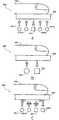
도 3A 내지 도 3C는 상이한 조명 파장 및/또는 상이한 편광 조건을 제공하는 본 발명의 다른 실시형태에 따른 다중분광 데이터의 수집을 허용하는 생체계측 센서를 나타낸 도면;3A-3C illustrate biometric sensors that allow the collection of multispectral data according to another embodiment of the present invention providing different illumination wavelengths and / or different polarization conditions;
도 4는 다수의 조명 및 검출 각도를 제공하는 본 발명의 다른 실시형태에 있어서의 다중분광 데이터의 수집을 허용하는 생체계측 센서를 나타낸 도면;4 illustrates a biometric sensor that allows the collection of multispectral data in another embodiment of the present invention providing multiple illumination and detection angles;
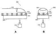
도 5A 및 도 5B는 각각 다수의 초점 평면을 제공하는 또 다른 실시형태에 있어서의 다중분광 데이터의 수집을 허용하는 생체계측 센서의 측면도 및 정면도;5A and 5B are side and front views of a biometric sensor that allows collection of multispectral data in another embodiment, each providing multiple focal planes;
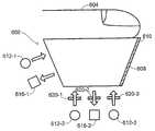
도 6은 다수의 조명 파장, 다수의 편광 조건, 다수의 조명 각도, 다수의 검출 각도 및 다수의 영상 평면에 의한 다중분광 데이터의 수집을 허용하도록 도 3A 내지 도 5B의 생체계측 센서의 양상을 조합한 생체계측 센서를 나타낸 도면;6 combines aspects of the biometric sensors of FIGS. 3A-5B to allow collection of multispectral data by multiple illumination wavelengths, multiple polarization conditions, multiple illumination angles, multiple detection angles, and multiple image planes. A biometric sensor shown;
도 7은 본 발명의 생체계측 센서의 플래튼 상에의 단일 배치 동안 건조 피부를 가진 손가락을 영상화하는 데 사용된 3개의 상이한 광학 형태로부터의 원래 영상 및 처리된 영상을 나타낸 도면;7 shows original and processed images from three different optical forms used to image a finger with dry skin during a single placement on the platen of the biometric sensor of the present invention;
도 8은 본 발명의 생체계측 센서의 플래튼과 최소 접촉하고 있는 손가락을 영상화하는 데 사용된 3개의 상이한 광학 형태로부터의 원래 영상 및 처리된 영상을 나타낸 도면.FIG. 8 shows original and processed images from three different optical forms used to image a finger in minimal contact with the platen of the biometric sensor of the present invention.
발명의 상세한 설명Detailed description of the invention
본 발명의 실시형태는 단일의 조명기간 동안 상이한 광학 조건 하에 획득된 피부 부위의 다수의 영상을 이용하는 생체계측 기능수행 장치 및 방법을 제공한다. 이와 같이 해서, 상기 영상은 생체계측 특징의 확실한 정의를 산출하기 위해 다양한 방법으로 조합될 수 있는 피부 부위에 대한 상이한 정보를 포함한다. 단일의 조명기간의 사용은 피부 부위의 실질적인 고정 위치에 대해서 영상이 생성되는 것을 허용하여, 영상들 간의 특징의 상대적인 배향에 있어서의 불확실한 것들을 제거함으로써, 정확도의 증가와 처리 요건의 감소를 가져온다.Embodiments of the present invention provide an apparatus and method for performing biometric function using multiple images of skin regions obtained under different optical conditions during a single illumination period. In this way, the image contains different information about the skin area that can be combined in various ways to yield a clear definition of the biometric features. The use of a single illumination period allows the image to be generated with respect to a substantially fixed position of the skin area, eliminating uncertainties in the relative orientation of the features between the images, resulting in increased accuracy and reduced processing requirements.
용어 "생체계측"이란 일반적으로 살아있는 생체의 특성의 통계학적 분석에 관한 것이다. 생체계측의 하나의 범주는 사람의 자동 확인(automatic identification)(혹은 자동 식별)을 제공하거나 사람의 주지된 신원을 검증하기 위해 2개의 모드 중 하나 하에 공통적으로 작용하는 "생체계측 확인"을 포함한다. 본 명세서에서 사용되는 바와 같이, "생체계측 특징"(또는 단지 "특징"이라고 칭할 경우도 있음)이란 생체계측 확인, 신원 검증, 샘플 진위성의 판정, 생존 등의 생체계측 과업과 관련된 정보를 포함하는 영상 부분 또는 영상의 세트를 의미하는 것으로 의도된다. 용어 "부분"이란 대상의 전체를 배제한 대상의 일부를 의미하는 것으로 의도되며, 따라서, 영상의 "부분"이란 전체 영상이 아닌 영상의 일부를 의미 한다. 그러므로, 다른 특정 실시형태에 있어서, 영상의 부분은 영상의 면적의 10% 미만의 면적, 영상의 면적의 5% 미만의 면적, 영상의 면적의 2% 미만의 면적, 영상의 면적의 1% 미만의 면적, 영상의 면적의 0.5% 미만의 면적, 영상의 면적의 0.2% 미만의 면적, 영상의 면적의 0.1% 미만의 면적 또는 영상의 면적의 다른 분획을 가진 영상의 일부를 의미할 수 있다.The term "biosystemic side" generally relates to statistical analysis of the characteristics of living organisms. One category of biometrics includes "biometric identification" that acts commonly under one of two modes to provide automatic identification (or automatic identification) of a person or to verify a person's known identity. . As used herein, "biosystemic feature" (or sometimes referred to as "feature") includes information related to biometric tasks such as biometric verification, identity verification, determination of sample authenticity, survival, and the like. It is intended to mean an image part or set of images. The term "part" is intended to mean a part of the object that excludes the entirety of the object, and thus, "part" of the image refers to a part of the image that is not the entire image. Therefore, in another particular embodiment, the portion of the image is less than 10% of the area of the image, less than 5% of the area of the image, less than 2% of the area of the image, less than 1% of the area of the image. It may mean a portion of an image having an area of, an area less than 0.5% of the area of the image, an area less than 0.2% of the area of the image, an area less than 0.1% of the area of the image, or another fraction of the area of the image.
따라서, 피부 부위가 손가락을 포함할 경우, 생체계측 특징은 지문 분야에서 충분히 공지된, 융기 분기점에서 또는 융기 단부에서 생기는 국소적인 지문 융기부 특성으로 되는 "미세특징점"(minutia point)을 포함한다. 상기 피부 부위가 손가락을 포함하는 다른 경우에 있어서, 상기 생체계측 특징은 지문의 융기부분과 골 부분에 의해 지문 영상의 일부에 형성된 특정 패턴일 수 있다.Thus, when the skin site comprises a finger, the biometric features include a "minutia point" which is a local fingerprint ridge characteristic that occurs at the ridge bifurcation or at the ridge end, which is well known in the fingerprint art. In other cases where the skin region comprises a finger, the biometric feature may be a specific pattern formed in a portion of the fingerprint image by the ridges and valleys of the fingerprint.
본 명세서에 기재된 계측에 적용가능한 피부 부위는 손가락이나 엄지손가락, 손톱이나 조상(nail bed), 손바닥, 손등, 손목, 팔뚝, 얼굴, 눈, 귀 및 기타 신체의 외표면 전체의 모든 표면이나 모든 관절(joint)을 포함한다. 이하의 설명에서는 특정 실시형태의 예를 제공함에 있어서 구체적으로 "손가락"을 참조하고 있는 경우가 있지만, 이들 실시형태는 단지 예시에 불과하며 다른 실시형태에서는 기타 신체 부분의 피부 부위를 이용할 수 있음은 물론이다.Skin areas applicable to the measurements described herein include fingers or thumbs, fingernails or nail beds, palms, backs of hands, wrists, forearms, faces, eyes, ears, and all surfaces or all joints of the entire outer surface of the body. (joint) Although the following description specifically refers to "fingers" in providing examples of specific embodiments, these embodiments are merely exemplary and other embodiments may use skin parts of other body parts. Of course.
단일의 조명기간 동안 복수의 별개의 광학 조건 하에 수집된 모든 영상의 세트는 본 명세서에서 "다중분광 데이터"라 칭한다. 상이한 광학 조건으로는 편광 조건차, 조명 각도차, 결상 각도차, 조명 파장차 및 영상화되는 피부 부위의 평면(본 명세서에서는 "초점 평면"이라 칭함)의 위치차 등을 포함할 수 있다. 일부의 광학 조건에 있어서, 얻어지는 영상은 샘플과 플래튼 간의 계면에서의 TIR 현상의 존재 및 분포에 의해 상당히 영향받는다. 이들 영상은 본 명세서에는 "TIR 영상"이라 칭한다. 일부의 광학 조건에 있어서, 얻어진 영상은 플래튼에서의 TIR 효과의 유무에 의해 실질적으로 영향받지 않는다. 이들 영상은 본 명세서에서 "직접 영상"이라 칭한다.The set of all images collected under a plurality of separate optical conditions during a single illumination period is referred to herein as "multispectral data." Different optical conditions may include polarization condition differences, illumination angle differences, imaging angle differences, illumination wavelength differences, and positional differences in the plane of the skin region being imaged (called "focal plane" herein), and the like. For some optical conditions, the resulting image is significantly affected by the presence and distribution of TIR phenomena at the interface between the sample and the platen. These images are referred to herein as "TIR images". For some optical conditions, the image obtained is substantially unaffected by the presence or absence of a TIR effect on the platen. These images are referred to herein as "direct images."
단지 예로서, 다중분광 데이터가 상이한 조명 파장에서 획득한 영상을 포함하는 실시형태는 근자외선(UV-A, 320 - 400 ㎚) 내지 중간 적외선(~ 5 ㎛)의 파장을 지닐 수 있다. 실리콘계 영상화 어레이는 약 300 ㎚ 내지 약 1100 ㎚로 다양한 검출가능한 파장의 범위를 가진 이러한 실시형태에서 사용될 수 있다. 이들 경우, 상기 조명 파장은 검출가능 범위 내에 놓이도록 선택하는 것이 유리할 수 있다. 몇몇 경우에 있어서, 상기 조명 파장은 가시 분광 영역(400 - 700 ㎚) 내이다. 본 명세서에서 이용된 바와 같이, "개별의 파장"이란 싱글 빈드 유닛(single binned unit)으로서 처리된 파장 또는 파장 대역의 세트를 의미하는 것으로 의도되어 있고, 각 빈드 유닛에 대해서, 정보는 빈드 유닛의 개별의 파장 서브세트로부터가 아니라 단지 빈드 유닛으로부터 전체로서 추출된다. 일부의 경우에 있어서, 빈드 유닛은 복수의 개별의 파장이 제공된 경우, 임의의 쌍의 파장 또는 파장 대역 사이의 소정의 파장이 제공되지 않지만, 이것은 필요하지 않다.By way of example only, embodiments in which multispectral data include images obtained at different illumination wavelengths may have wavelengths from near ultraviolet (UV-A, 320-400 nm) to mid-infrared (˜5 μm). Silicon-based imaging arrays can be used in such embodiments with a range of detectable wavelengths from about 300 nm to about 1100 nm. In these cases, it may be advantageous to select the illumination wavelength to fall within the detectable range. In some cases, the illumination wavelength is in the visible spectral region (400-700 nm). As used herein, "individual wavelength" is intended to mean a set of wavelengths or wavelength bands that have been treated as a single binned unit, and for each bin unit, information is defined as It is extracted as a whole not just from a separate subset of wavelengths but from the bind unit. In some cases, the wind unit is not provided any wavelength between any pair of wavelengths or wavelength bands when a plurality of individual wavelengths are provided, but this is not necessary.
다중분광 데이터가 상이한 편광 조건 하에서 획득된 영상을 포함하는 실시형태는 직교 편광 상태에서, 평행 편광 상태에서 및/또는 편광이 없는 상태에서 획득된 영상을 포함할 수 있다. 광의 편광은 선형 또는 타원형일 수 있다. 선형 편광 의 경우, "교차"란 편광기의 광축이 실질적으로 직교하는 것을 의미한다. 타원형 편광의 경우, "교차"란 편광기가 실질적으로 반대 의미(우측 원 대 좌측 원)인 것을 의미한다.Embodiments in which the multispectral data includes an image obtained under different polarization conditions may include an image obtained in an orthogonal polarization state, in a parallel polarization state and / or in a state without polarization. The polarization of the light can be linear or elliptical. In the case of linear polarization, "crossing" means that the optical axis of the polarizer is substantially orthogonal. In the case of elliptical polarization, "cross" means that the polarizer has a substantially opposite meaning (right circle to left circle).
다중분광 데이터가 상이한 조명에 의해 획득된 영상을 포함하는 실시형태는 피부 부위가 놓이게 되는 플래튼에 대해서 상이한 각도로 조명광을 제공함으로써 얻어질 수 있다. 일부의 경우에 있어서, 영상은 실질적으로 피부-플래튼 계면에 의해 형성된 임계각보다 작은 각도인 조명광으로부터 형성된다. 다른 경우에 있어서, 영상은 피부-플래튼 계면에 의해 형성된 임계각보다 실질적으로 큰 각도인 조명광으로부터 형성된다.Embodiments in which the multispectral data comprise images obtained by different illuminations can be obtained by providing illumination light at different angles with respect to the platen on which the skin region is to be placed. In some cases, the image is formed from illumination light that is substantially less than the critical angle formed by the skin-platen interface. In other cases, the image is formed from illumination light that is at an angle substantially greater than the critical angle formed by the skin-platen interface.
다중분광 데이터가 상이한 영상화 각도에서 획득된 영상을 포함하는 실시형태는 피부 부위가 놓이게 되는 플래튼에 대해서 상이한 각도로 배향된 검출기 어레이에 의해 얻어질 수 있다. 일부의 경우에 있어서, 영상의 일부는 피부-플래튼 계면에 의해 형성된 임계각보다 작은 각도에서 피부 부위를 관측하는 검출기 어레이로부터 형성된다. 다른 경우에는, 영상의 일부는 피부-플래튼 계면에 의해 형성된 임계각보다 큰 각도에서 피부 부위를 관측하는 검출기 어레이로부터 형성된다.Embodiments in which the multispectral data include images obtained at different imaging angles can be obtained by detector arrays oriented at different angles relative to the platen on which the skin region will be placed. In some cases, a portion of the image is formed from a detector array that observes the skin region at an angle less than the critical angle formed by the skin-platen interface. In other cases, a portion of the image is formed from a detector array that observes the skin region at an angle greater than the critical angle formed by the skin-platen interface.
다중분광 데이터가 상이한 초점 평면에서 획득된 영상을 포함하는 실시형태는 플래튼과 직접 접촉하지 않는 샘플의 영역을 적절하게 결상하도록 가변 초점 설정치를 갖는 영상 장치에 의해 얻어질 수 있다. 예를 들어, 이러한 제1 영상에 있어서, 영상 장치의 초점은 피부 부위와 플래튼 사이의 계면을 결상하도록 설정될 수 있다. 이러한 제2 영상에 있어서, 초점은 플래튼(즉, 샘플 쪽) 등의 위쪽의 소 정의 거리에 놓여 있는 상이한 평면을 결상하도록 재설정될 수 있다. 일부의 실시형태에 있어서, 이러한 가변 초점 영상기(imager)용의 영상 장치는 텔레센트릭하도록 구성되어, 초점 이탈 상태에 있는 부분에서도 일련의 중첩 영상을 제공한다.Embodiments in which the multispectral data include images obtained in different focal planes can be obtained by an imaging device having variable focus settings to properly image an area of the sample that is not in direct contact with the platen. For example, in this first image, the focus of the imaging device may be set to image the interface between the skin region and the platen. In this second image, the focus can be reset to image different planes lying at a predetermined distance above the platen (ie, sample side) or the like. In some embodiments, the imaging device for such a variable focus imager is configured to be telecentric, providing a series of superimposed images even in a portion that is out of focus.
실시형태는 대안적으로 혹은 부가적으로 예를 들어, 가변초점을 가진 영상 장치를 이용하는 대신에 혹은 그에 부가해서 비교적 큰 초점 심도이지만 고정 초점을 가진 영상 장치를 이용할 수 있다. 이러한 경우, 상기 영상 장치는 이와 같이 해서 적절한 초점 영역이 샘플의 보다 큰 부분을 적절하게 결상하도록 플래튼의 표면 및 상기 표면 위(즉, 샘플쪽 위)의 소정 거리를 포함하도록 설정될 수 있다. 일부의 경우에 있어서, 이러한 영상기는 텔레센트릭 영상화를 제공하여, 초점 이탈(out-of-focus) 영역이 다른 합초점(in-focus) 평면과 공간적으로 일치하는 것을 확실하게 한다.Embodiments may alternatively or additionally use, for example, an imaging device having a relatively large depth of focus but having a fixed focus instead of or in addition to using an imaging device having a variable focus. In this case, the imaging device may be set in this way so that the appropriate focal region comprises a predetermined distance on the surface of the platen and on the surface (ie on the sample side) so as to adequately image a larger portion of the sample. In some cases, such imagers provide telecentric imaging to ensure that out-of-focus areas are spatially coincident with other in-focus planes.
단지 예로서, 피부 부위가 손가락을 포함하는 경우에 있어서, 상이한 초점 평면에 대해서 제공하는 실시형태는 지문 특징 이외의 특징이 영상 평면의 일부 또는 모두로부터 추출되는 것을 허용한다. 예를 들어, 심혈관과 같은 이러한 특징은 혈액에 의해 고도로 흡수된 파장에 의해 영상 평면의 하나 이상을 이용해서 검출될 수 있고, 이것은 대략 540 ㎚ 및 576 ㎚에서의 산소화된 헤모글로빈 피크를 포함할 수 있다. 일부의 경우에 있어서, 다수의 조명 파장에 대응하는 다수의 영상 평면이 분석되어, 혈액 또는 다른 피부 구성요소에 대응하는 스펙트럼 사인(spectral signature)을 가진 특징을 확인한다.By way of example only, where the skin region comprises a finger, the embodiments that provide for different focal planes allow features other than the fingerprint feature to be extracted from some or all of the image plane. For example, such a feature as cardiovascular can be detected using one or more of the image planes by wavelengths absorbed highly by the blood, which can include oxygenated hemoglobin peaks at approximately 540 nm and 576 nm. . In some cases, multiple image planes corresponding to multiple illumination wavelengths are analyzed to identify features with spectral signatures corresponding to blood or other skin components.
본 발명의 방법은 도 1의 순서도에 요약되어 있다. 도 1에서는 특정 실시형 태로 수행될 수 있는 다수의 공정을 설명하고 있지만, 본 발명은 기타 다른 실시형태도 망라한다. 특히, 표시된 단계의 순서는 제한하기 위해 의도된 것은 아니며, 상기 순서도에 있어서의 특정 단계의 포함은 제한하기 위해 의도된 것은 아니며, 즉, 일부의 대안적인 실시형태에 있어서 단계 중의 일부는 생략될 수 있고, 또, 다른 일부의 대안적인 실시형태에 있어서는 명확하게 표시되지 않은 몇몇 부가적인 단계가 부가적으로 수행될 수 있다.The method of the present invention is summarized in the flowchart of FIG. 1. Although FIG. 1 illustrates a number of processes that can be performed in a particular embodiment, the invention encompasses other embodiments. In particular, the order of steps indicated is not intended to be limiting, and the inclusion of specific steps in the flowcharts is not intended to be limiting, ie, in some alternative embodiments some of the steps may be omitted. In addition, in some alternative embodiments, some additional steps that are not explicitly indicated may be additionally performed.
이 방법은 사용자가 생체계측 센서의 플래튼 상에 피부 부위를 배치시킨 상태의 블록(104)에서 시작된다. 이하에서는 "피부 부위"를 참조해서 설명하지만, 본 명세서에 설명된 다중분광수법이 실체 살아 있는 조직과 다양한 속임(spoof) 간을 구별하는 능력을 가지므로, 본 발명의 실시형태는 임의의 목적으로 하는 피부 부위의 분석 및 감지에 대해 더욱 일반적으로 적용가능한 것임을 인식할 필요가 있다. 다중 분광 계측은 피부 부위에 대해 수행되고, 이때의 계측 순서는 실시형태에 따라 수동으로 혹은 자동으로 개시된다. 자동 개시는 광학 스위치, 전기용량성 스위치, 압력 스위치, 기계식 스위치 등을 포함하는 기구에 의해 수행될 수 있고, 적절하게 위치결정시켜 피부 부위의 배치를 실시간으로 검출하는 영상 처리를 행하는 1개 이상의 카메라를 이용하는 것이 유리하다.The method begins at
계측 순서는 다중분광 조건하에서 피부 부위를 조명하는 블록(108)에서 시작될 수 있다. 이러한 조명은 일반적으로 피부 부위의 실질적인 고정 위치에 대해서 단일의 조명기간 수행된다. 당업자라면, 단일의 조명기간에서도, 다중분광 조건하에서의 조명이 실질적으로 동시에 얻어질 수 있거나 또는 순차로 얻어질 수 있음을 알 수 있을 것이다. 조명이 실질적으로 동시 또는 순차인지의 여부는 다중 분광 조건의 특정 성질에 따라 부분적으로 의존할 수 있고, 이하의 특정 구조의 상이한 예는 실질적으로 동시 조명이 소정 유형의 다중분광 조건에 대해서 달성될 수 있는 형태를 예시하고 있다. 조명이 순차 행해질 경우, 상기 순서는 해당 순서 동안 피부 부위의 이동이 최소로 되는 충분히 작은 시간, 통상 1초 미만의 기간이다.The metrology sequence may begin at
따라서, 광이 블록(112)에서 피부 부위로부터 수광된다. 수광된 광은 플래튼-피부 계면으로부터와 같이 피부 부위의 표면에서 반사된 광을 포함할 수 있고/있거나, 피부 부위의 표면 밑으로부터 산란된 광을 포함할 수 있다. 이러한 하위표면(subsurface) 산란은 전통적인 지문-영상화 수법에서는 이용될 수 없는 정보를 제공한다. 특히, 하위표면 생체계측 정보를 추출하는 능력은 표면 특징이 빠지거나 손상된 경우에 있어서도 생체계측 판정을 수행하는 기구(mechanism)를 제공한다. 이와 같이 해서, 본 발명의 실시형태는 유리하게는 상당한 수공 노동을 행하는 중장년층의 사람 혹은 미용사나 간호사 등의 화학약품에 피부가 노출되는 사람과 전형적으로 관련된 닳게 된 특징, 탄성 부족, 과잉의 축축함 및/또는 건조 등의 이상적이지 않은 피부 품질에 대해서 강인하다.Thus, light is received from the skin site at
영상은 소정 방식의 처리에 의해 블록(116)에서 수광된 광으로부터 생성된다. 처리는 단일의 복합 영상으로부터 상이한 영상의 추출을 포함할 수 있다. 처리는 또한 히스토그램 평활화(histogram equalization), 조영 증강(contrast enhancement), 에지 강화(edge enhancement), 노이즈 필터링(noise filtering) 등의 영상-처리 공정을 포함할 수 있다. 영상 분할(segmentation)은 영상 배경을 은 폐하여 샘플이 존재하는 그 영역을 가까스로 남기도록 수행될 수 있다. 블록(120)에 나타낸 바와 같이, 처리는 또한 하나 이상의 영상에 대해 변환을 수행하여 하나의 영상을 다른 영상과 공간적으로 일치시키는 것을 포함할 수도 있다. 영상 간의 공간적 관계의 확인은 다수의 영상 간의 확인된 생체계측 특징의 존재를 상관시키는 것을 허용한다.The image is generated from the light received at
이러한 생체계측 특징을 추출하기 위한 영상의 처리는 블록(124)에서 수행된다. 예를 들어, 피부 부위가 손가락을 포함하는 실시형태에 있어서, 미세특징점은 개별 영상의 각각에 대해서 발견될 수 있다. 마찬가지로, 융기부분과 골 부분의 전체 패턴이 결정될 수 있고, 또는 지문의 핵심 영역과 같은 대상으로 하는 특정 영역이 영상에 대해 확인될 수도 있다. 몇몇 경우에 있어서, 소정 영상 또는 영상의 배합은 혈액 특징 또는 영상에 존재하는 기타 분광학적으로 별개의 특성을 결정하도록 분석될 수도 있다. 생체계측 특징은 사인파(sinusoid), 가버 필터(Gabor filter) 또는 각종 웨이브렛(wavelet) 등의 적절한 세트의 기본 함수 상에 국소 영역에서의 지문 특징의 분해에 의해 형성된 계수의 세트를 포함할 수 있다. 생체계측 특징의 이러한 확인은 유리하게는 영상에 존재하는 인위 구조에 기인하는 종래 부작용을 피할 수 있다. 따라서, 이 확인은 피부 건조와 같은 각종 인자가 극히 낮은 조영의 영상을 초래하므로, 융기 부분이 비연속적으로 나타나게 되어 간단한 영상 인위 구조로부터 미세특징점을 구별하는 것이 곤란해지는 종래의 지문 영상에서의 확인과는 다르다.Processing of the image to extract such biometric features is performed at
생체계측 특징이 복수의 영상 평면상에서 발견되는 실시형태에 있어서, 이들 특징은 블록(12)으로 표시된 바와 같이 조합될 수 있다. 영상은 서로 공간적으로 관련되어 있고 동일한 피부 부위 배치를 나타내므로, 특징의 위치는 영상 간에 잘 정의되어 있다. 따라서, 특징은 평균화 등의 적절한 수학적 연산에 의해, 논리 "곱"(and), 논리 "합"(or) 등의 이러한 논리 조합 연산에 의해, 또는 영상 평면을 가로지르는 특정 특징의 존재를 채택함으로써 개별적으로 평가하고 조합될 수 있다. 이 조합된 특징 세트는 영상 평면이 특징 유형 혹은 기원의 일부의 다른 지정자(designator) 또는 그로부터 유래된 개별의 특징을 가지는 일부의 표시를 포함할 수 있다.In embodiments in which biometric features are found on a plurality of image planes, these features may be combined as indicated by block 12. Since the images are spatially related to each other and represent the same skin site placement, the location of the features is well defined between the images. Thus, features may be selected by appropriate mathematical operations such as averaging, by such logical combination operations such as logical "and", logical "sum" (or), or by adopting the presence of certain features across the image plane. Can be evaluated and combined individually. This combined feature set may include some indications in which the image plane has other designators of the feature type or part of origin, or individual features derived therefrom.
예를 들어, 복합 특징은, 그 특징(예를 들어, 미세특징점)이 그 위치에서 적어도 1개의 영상 평면에 존재할 경우 복합 특징이 지정된 위치에 존재하는 것을 표명하는 규칙에 의해 일 실시형태에서 생성될 수도 있다. 다른 실시형태에 있어서, 복합 특징은 그 특징이 소정의 위치에서 영상 평면의 적어도 절반(또는 일부의 다른 특정 분획)에 존재할 경우 그 위치에 존재하는 것으로 표명될 것이다.For example, a compound feature may be generated in one embodiment by a rule stating that the compound feature exists at a specified location when that feature (eg, a microfeature point) is present in at least one image plane at that location. It may be. In other embodiments, a composite feature will be declared to be present at that location if the feature is present at at least half (or some other specific fraction of the image plane) at a given location.
다른 실시형태는 그 특징이 복합 특징의 존재를 표명할 수 있는 그 위치에서 영상 평면 모두에 존재하는 것을 필요로 할 수 있다. 추가의 실시형태에 있어서, 복합 특징은 단지 특징 위치 근방에 동일함을 식별할 수 있는 특성을 가진 영상 평면의 모두에 상기 특징이 존재한다면 지정된 위치에 복합 특징이 존재하는 것을 표명하는 규칙에 의해 생성될 수 있다. 복합 특징의 존재를 표명하기 위해 다른 실시형태에서 적용될 수 있는 또 다른 규칙은 본 명세서를 읽은 당업자에게 명백해질 것이다.Other embodiments may require that the feature be present in both of the image planes at that location that can manifest the presence of the composite feature. In a further embodiment, the composite feature is generated by a rule that states that the composite feature exists at a specified location if the feature is present in all of the image planes having a characteristic that can only be identified near the feature location. Can be. Another rule that may be applied in other embodiments to declare the presence of complex features will be apparent to those of ordinary skill in the art having read this specification.
영상으로부터의 정보는 블록(124)의 특징-추출 단계 전에 명백하게 그 프로세스에 있어서 상이한 스테이지에서 조합될 수 있다. 일부의 실시형태에 있어서. 예를 들어, 원래의 영상은 화소간(pixel-by-pixel) 합계에 의하는 등의 소정의 방법으로 조합될 수 있거나, 또는, 미리 처리된 영상이 소정 방법으로 조합될 수도 있다. 다른 예에 있어서, 가버 웨이브렛(Gabor wavelet) 계수 또는 그래디언트 필드(gradient field) 등의 영상으로부터 유도된 값은 평균, 로버스트 평균(robust mean), 중앙값(median) 등을 구하는 등의 계산을 통해 조합될 수 있다.Information from the image may be combined at different stages in the process, apparently before the feature-extraction step of
또한, 일부의 실시형태에 있어서, 특징은 영상의 조합을 조사함으로써 확인될 수 있다. 단지 예로서, 일 실시형태에 있어서, 혈액 특징은 혈액의 공지된 흡수 스펙트럼에 의거해서 복수의 조명 파장에 대응하는 영상 세트의 각각에 있어서 각 화소 위치에 존재하는 혈액량을 추정함으로써 알아낼 수도 있다. 고전적인 최소-제곱법 평가(least-squares estimation) 및 각종 기타 공지의 평가법 등의 수학적 절차는 이러한 분석을 수행하는 데 이용될 수 있다.Also, in some embodiments, features can be identified by examining a combination of images. By way of example only, in one embodiment, the blood feature may be found by estimating the amount of blood present at each pixel location in each of a set of images corresponding to a plurality of illumination wavelengths based on known absorption spectra of the blood. Mathematical procedures such as classical least-squares estimation and various other known methods can be used to perform this analysis.
특징의 세트는 등록, 검증, 확인 및/또는 속임 검출 등의 생체계측 기능을 수행하기 위해 전형적인 생체계측 조작 하에 처리될 수도 있다. 예를 들어, 피부 부위를 공급한 개체가 확인될 수 있거나, 그의 신원이 검증될 수 있다. 이러한 생체계측 기능은 상기 생체계측 특징의 유도된 조합을 특징의 데이터베이스와 비교함으로써 블록(132)으로 나타낸 바와 같이 일부의 실시형태에 있어서 수행될 수 있다. 예를 들어, 데이터베이스는 등록 프로세스의 일부로서 많은 개체로부터 얻어진 생체계측 특징의 조합의 사양을 포함할 수 있고, 이때, 상기 생체계측 기능은 블록(128)에서 생성된 조합을 데이터베이스에 있어서의 기입 사항과의 비교를 통해 블록(132)에서 수행된다.The set of features may be processed under typical biometric manipulations to perform biometric functions such as registration, verification, validation and / or cheat detection. For example, the individual who supplied the skin site can be identified or its identity can be verified. Such biometric functionality may be performed in some embodiments as indicated by block 132 by comparing the derived combination of biometric features with a database of features. For example, the database may include a specification of a combination of biometric features obtained from many individuals as part of the registration process, where the biometric function writes the combination generated in
도 1의 방법(들)을 수행하는 데 적합한 생체계측 장치의 구조의 일반적인 개요는 도 2의 개략도에 의해서 제공된다. 도 2는 개별적인 시스템 요소가 분리된 또는 더욱 일체화된 방법으로 이행될 수 있는 방법을 대략적으로 예시하고 있다. 생체계측 장치(200)는 버스(226)를 통해 전기 결합된 하드웨어 요소로 구성된 것을 나타내고 있다. 이 하드웨어 요소는 프로세서(202), 입력 장치(204), 출력 장치(206), 기억 장치(208), 컴퓨터 판독가능한 기억 매체 판독기(210a), 통신 시스템(214), DSP 또는 공간전용 프로세스 등의 처리가속부(204) 및 메모리(218)를 포함한다. 컴퓨터 판독가능한 기억 매체 판독기(210a)는 원격, 국소, 고정 및/또는 제거가능한 기억 장치 + 컴퓨터 판독가능한 정보를 일시적으로 및/또는 영구적으로 수용하는 기억 매체를 일괄적으로 나타내는 조합체인 컴퓨터 판독가능한 기억 매체(210b)와 더욱 접속된다. 통신 시스템(214)은 유선, 무선, 모뎀 및/또는 다른 유형의 인터페이스 접속부를 포함할 수 있고, 데이터는 외부 장치와 교환될 수 있다. 다중분광 데이터는 생체계측 센서(256)에 의해 수집되고, 이것은 또한 버스(226)를 통해서 전기적으로 결합될 수도 있다.A general overview of the structure of a biometric device suitable for performing the method (s) of FIG. 1 is provided by the schematic diagram of FIG. 2. 2 schematically illustrates how individual system elements may be implemented in a separate or more integrated manner. The
상기 생체계측 장치(200)는 또한 연산 시스템(224) 및 본 발명의 방법을 수행하도록 설계된 프로그램 등의 기타 코드(222)를 포함하는 작업 메모리(220) 내에 현재 위치되어 있는 것으로 표시된 소프트웨어 소자를 포함한다. 당업자에게 명백한 바와 같이 실질적인 변경은 특정 요건에 따라 이용될 수 있다. 예를 들어, 맞 춤형 하드웨어가 이용될 수도 있고/있거나 특정 요소가 하드웨어, 소프트 웨어(애플릿(applet) 등의 휴대용 소프트웨어를 포함함), 또는 이들 모두에서 수행될 수도 있다. 또한, 네트워크 입/출력 장치 등의 기타 컴퓨터 장치와의 접속도 이용될 수 있다.The
상이한 실시형태에 있어서의 생체계측 센서(256)에 사용될 수 있는 각종 상이한 구조가 도 3A 내지 도 6에 예시의 목적으로 제공된다. 예를 들어, 도 3A는 다중분광 조건을 제공함에 있어서 다수의 조명 파장을 편입한 생체계측 센서(300)의 일례를 나타내고 있다. 다중 파장은 일반적으로 생체계측 기능의 일부로서 사용자에 의해 제공되는 손가락 또는 기타 조직의 상이한 구성요소에 따라 다르게 상호작용할 것이다. 예를 들어, 대략 600 ㎚ 미만의 파장은 혈액에 의해 강하게 흡수되고, 산소화 헤모글로빈으로 인해 대략 540 ㎚ 및 576 ㎚에서 특히 강한 피크를 가진다. 또한, 일반적으로, 보다 긴 파장의 광(예를 들어, 적색광 또는 적외광)은 피부에 더욱 깊게 침투하여, 더욱 깊은 구조에 의해 영향받으며, 보다 짧은 파장(예를 들어, 청색광 또는 근자외선)은 덜 깊게 침투하고, 표면 및 표면 근처 피부 구조에 의해 강력하게 영향받는다.Various different structures that may be used for
도3a에 있어서의 피부 부위(304)는 해당 피부 부위(304)를 조명하는 데 사용되는 파장에서 투명 혹은 반투명일 수 있는 플래튼(308) 상에 놓인다. 디지털 카메라 등의 광 검출기(312)를 이용해서, 각종 렌즈, 미러 및/또는 기타 광학 요소(도 3A에는 도시되어 있지 않음)를 이용하여 플래튼(308)과의 계면 근방에 피부 부위(304)의 피부의 영상을 형성한다. 검출기(312)는 넓은 범위의 파장에 대해서 민 감할 수 있다. 몇몇 경우에 있어서, 검출기(312)는 실리콘 디지털 촬상 칩을 편입시킬 수 있다. 이러한 실리콘계 카메라는 대략 350 ㎚ 내지 1100 ㎚에 걸친 넓은 범위의 파장을 검출할 수 있는 "흑백"(black and white) 카메라일 수 있다.
조명원(혹은 광원)(310)은 상이한 파장의 준단색 공급원으로서 제공될 수 있다. 적절한 조명원(310)으로는 발광다이오드(LED), 레이저, 레이저 다이오드, 양자점(quantum dot), 여파된(infiltered) 백열광원 등을 들 수 있다. 검출기(312)가 실리콘계 센서를 포함하는 실시형태에 있어서, 광원(310)의 파장은 대략 350 ㎚ 내지 1100 ㎚의 범위에 놓이도록 선택될 수 있다. 일 실시형태에 있어서, 광원은 대략 400 내지 700 ㎚의 가시 영역에 있다. 각 광원(310)으로부터의 광은 다양한 방법을 이용해서 확산되어 피부 부위(304)를 향하게 될 수 있다. 예를 들어, 광은 렌즈 및/또는 미러 등의 이러한 광학 소자를 이용해서 확대되어, 평형하게 될 수 있다. 이 광은 반투명 유리소재, 유백색 유리, 홀로그래픽 확산자, 반투명 플라스틱 및 당업계에 공지된 기타 기구의 단편 등의 산란 매체를 이용해서 확산될 수 있다.Illumination source (or light source) 310 may be provided as a quasi-monochrome source of different wavelengths. Suitable illumination sources 310 include light emitting diodes (LEDs), lasers, laser diodes, quantum dots, infiltered incandescent light sources, and the like. In embodiments where the
센서(300)의 동작 수순은 순차 조명일 수 있고, 여기서, 특정 파장의 제1 광원(310-1)이 조명되어 검출기(312)가 영상을 획득해서 보존할 수 있게 하고, 이어서, 제1 광원(310-1)은 소광되고, 제2 광원(310-2)이 조명되고 나서, 검출기(312)는 다음 영상을 획득하여 보존한다. 이 수순은 모든 광원(310)에 대해 계속되고, 수회 반복될 수 있다. 또는, 각 광원(310)은 임의의 단일 주파수에서 변조될 수 있고, 이때 검출기(312)는 조명 변조 주파수의 어느 것보다도 크게 다른 주파수에 서 일련의 영상을 획득한다. 다음에, 얻어진 영상이 분석되어, 당업계에 공지된 방법을 이용해서 개별의 조명 파장의 기여도를 추정할 수 있다.The operation procedure of the
도 3B는 다중 파장 실시형태의 변형예를 나타내고 있다. 이 경우, 생체계측 센서(300')는 비여파된 백열등이나 백색광 LED 등의 광대역 공급원으로서 제공되는 조명원(316)을 포함한다. 도 3A의 실시형태에 있어서의 검출기(312)의 기능성에 부가해서, 검출기(320)는 광학 여파 동작을 수행하기 위해 장착되어 있다. 이것을 행하는 하나의 방법은 컬러 카메라 상에 통상 이용되는 베이어 패턴(Bayer pattern)과 유사한 결상 어레이의 표면상에 컬러 필터 어레이(도시 생략)를 편입시키는 것이다. 다른 방법은 상이한 컬러 영상을 다중 검출기로 향하게 하는 컬러 빔 스플리터를 편입시키는 것이다.3B shows a variation of the multi-wavelength embodiment. In this case, the biometric sensor 300 'includes an
도 3B에 표시된 장치의 동작의 순서는 이와 같이 해서 광대역 공급원(316)이 조명된 후 1개 이상의 영상을 수집하기 위한 것이다. 개별의 컬러 영상은 다음에 컬러 필터 어레이의 경우 서브화소의 세트로서 추출되거나 또는 컬러 빔 스플리터의 경우 개별의 검출기로부터 독출(read out)될 수 있다.The order of operation of the device shown in FIG. 3B is thus to collect one or more images after the
도 3C는 피부 부위(304)의 다수의 상이한 영상을 회수하기 위해 상이한 편광 조건을 편입시키는 생체계측 센서(300")를 나타내고 있다. 광의 편광은 조직 혹은 기타 산란 매체에서 일어나는 광학 산란에 의해 영향받는다. 이 때문에, 교차 선형 편광기는 표면반사에 대항해서 식별되고, 조직에서 더욱 깊게 상호 작용되는 광을 강조하기 위해 수행될 수 있다. 마찬가지 방식으로, 평행 선형 편광 및 각종 타원 편광 구성은 조직의 상이한 특징을 강조하기 위해 이용될 수 있다. 관련된 방법에 있어서, 편광, 특히 선형 편광은 프레넬 반사(Fresnel reflection) 현상을 통해 광학 계면에서 일어나는 반사의 크기에 영향을 미친다. 이와 같이, 상이한 선형 편광 배향은 1개 이상의 계면으로부터 반사된 광을 강조하거나 혹은 강조하지 않기 위해서 이용될 수 있다.3C shows a
도 3C에 있어서, 피부 부위(304)는 광원(324)에 의해 플래튼(308)을 통해 조명되고, 도 3A 및 도 3B와 관련해서 설명된 것과 마찬가지 방법으로 검출기(328)에 의해 결상된다. 광원(324)은 준단색 혹은 광대역일 수 있고, 검출기(328)는 이들 도면과 관련하여 설명된 방법에 있어서 흑백 혹은 컬러일 수 있다. 조명원(324)의 일부(또는 전부)로부터의 광은 편광소자(332-1)에 의해 편광될 수 있다. 편광기(332-1)는 상이한 실시형태에 있어서 선형 편광기 또는 타원형 편광기를 포함할 수 있다. 마찬가지로, 일부의 검출기(328)는 제2 편광기(332-2)를 통해 영상을 관측할 수 있고, 또한, 상이한 실시형태에 있어서 선형 혹은 타원 편광기일 수도 있다.In FIG. 3C,
일 실시형태에 있어서, 조명 편광기(332-1) 및 검출 편광기(332-2)는 2개의 편광기(332)의 광축이 실질적으로 직교하도록 배열된 선형 편광기이다. 다른 경우에 있어서, 실질적으로 평행 편광을 지니도록 편광기(332)가 배열되어 있다.In one embodiment, the illumination polarizer 332-1 and the detection polarizer 332-2 are linear polarizers arranged such that the optical axes of the two polarizers 332 are substantially orthogonal. In other cases, the polarizer 332 is arranged to have substantially parallel polarization.
어느 한쪽 편광기(332)가 타원형 편광기를 포함할 경우, 타원형 편광기 앞에는 해당 타원형 편광기의 축에 대해서 소정 각도로 배향된 선형 편광기(도 3C에는 도시되어 있지 않음)가 선행될 수 있다. 이 각도는 당업자에게 공지된 방법으로 우측 원형 광 혹은 좌측 원형 광을 생성하도록 선택될 수 있다. 일 실시형태에 있 어서, 편광기(332)에 의해 구성된 타원형 편광기는 두 편광기(332)가 모두 왼쪽 원형광을 생성하거나 두 편광기(332)가 모두 오른쪽 원형광을 생성하도록 배열된다. 다른 실시형태에 있어서, 하나의 편광기(332)는 왼쪽 원형광을 생성할 수 있는 한편, 다른쪽 편광기(332)는 오른쪽 원형광을 생성한다.When either polarizer 332 includes an elliptical polarizer, a linear polarizer (not shown in FIG. 3C) oriented at an angle with respect to the axis of the elliptical polarizer may be preceded by the elliptical polarizer. This angle may be selected to produce right circular light or left circular light in a manner known to those skilled in the art. In one embodiment, the elliptical polarizer configured by polarizer 332 is arranged such that both polarizers 332 produce left circular light or both polarizers 332 produce right circular light. In another embodiment, one polarizer 332 can generate left circular light while the other polarizer 332 produces right circular light.
도 3C에 표시된 바와 같이, 편광 검출기(328-1)에 의해 관찰되는 조명 조건을 생성하는 비편광원(324)도 존재할 수 있다. 실시형태는 또한 편광원(324-2)으로부터의 광을 이용해서 생성되는 영상을 관측하는 비편광 카메라(328-2)를 구비할 수도 있다.As indicated in FIG. 3C, there may also be a non-polarization source 324 that creates an illumination condition observed by polarization detector 328-1. Embodiments may also include a non-polarization camera 328-2 that observes an image generated using light from polarization source 324-2.
다수의 각도의 조명 및 결상의 이용은 도 4에 나타낸 생체계측 센서에 의해 예시되어 있다. 조명 또는 검출 각도의 변화는 일반적으로 광학 계면으로부터 투과 혹은 반사된 광의 크기 및/또는 검출의 변화를 초래한다. 임계 각도로서 알려진 소정의 각도에서, 두 상이한 굴절계수의 매체 사이의 계면은 전내부 반사 효과를 산출할 수 있다. 플래튼-공기 임계 각도의 어느 쪽 상의 플래튼과 접촉한 피부 부위의 관측시 명백하게 상이한 정보 내용을 가진 현저하게 상이한 영상을 생성할 수 있다. 또한, 다양한 편광 효과뿐만 아니라 외부 지문 패턴 등의 불규칙 특징에 대해서 일어나는 가능한 쉐도우-캐스팅(shadow-casting) 효과도 있다. 이들 종류의 효과는 모두 조명 및 검출의 상이한 광학 각도 하에 영상기에 의해 생성된 영상의 성질을 변화시킨다.The use of multiple angles of illumination and imaging is illustrated by the biometric sensor shown in FIG. 4. Changes in illumination or detection angle generally result in changes in the magnitude and / or detection of light transmitted or reflected from the optical interface. At a given angle, known as the critical angle, the interface between the media of two different refractive indices can produce a total internal reflection effect. Observation of the skin area in contact with the platen on either side of the platen-air critical angle can produce significantly different images with clearly different information content. In addition to the various polarization effects, there are also possible shadow-casting effects that occur on irregular features such as external fingerprint patterns. These kinds of effects all change the nature of the image produced by the imager under different optical angles of illumination and detection.
도 4는 플래튼으로서 작용하거나 플래튼을 구성하는 프리즘(408)을 통해 피부 부위(404)를 조명하는 복수의 조명원(412)을 나타내고 있다. 또한, 프리 즘(408)을 통해서 피부 부위(404)를 관찰하는 복수의 검출기(416)도 있다. 프리즘의 이용은 광이 플래튼 재료에 입사하거나 떠나는 계면에서 발생하는 광학 효과를 최소화한다. 대안적으로, 마이크로프리즘 어레이 및 단순한 평면 윈도를 비롯한 다른 형태의 플래튼이 이용될 수 있다. 도면에 있어서, 조명원(412)으로부터의 광은 피부 부위(404)를 조명하기 전에 준평행화될 수 있다. 검출기(416)의 어느 하나 혹은 모두는 피부 부위(404)가 조명원(412)의 어느 하나 혹은 모두에 의해 조명된 경우 영상 데이터를 수집할 수 있다. 몇몇 경우에 있어서, 도면에 있어서의 조명원(412-1)과 같은 1개 이상의 광원은 플래튼-공기 계면에 의해 규정된 임계 각도보다 큰 각도로 배향되어, 피부 부위(404)와 플래튼 사이의 계면에서 전내부 반사 효과를 초래할 수 있다. 몇몇 경우에 있어서, 도면에 있어서의 검출기(416-1)와 같이 1개 이상의 검출기는 마찬가지로 플래튼-공기 계면에 의해 규정된 임계 각도보다 큰 각도로 배향되어, 검출기에 의해 생성된 영상이 전내부 반사 효과에 의해 영향받게 될 수 있다.4 illustrates a plurality of illumination sources 412 that illuminate the
도 5A 및 도 5B는 다수의 초점 평면을 가지는 영상을 수집할 수 있는 생체계측 센서(500)의 부분을 나타낸다. 도 5A는 이러한 생체계측 센서(500)의 측면도를 나타내는 한편, 도 5B는 센서(500)의 정면도를 나타낸다. 피부 부위(504)는 플래튼(508)에 놓인다. 도 5B의 측면도는 피부 부위(504)가 곡선 신체부에 의해, 예를 들어, 손가락 등에 의해 구성되어, 플래튼(508)과 접촉하지 않는 영역을 갖는 경우 그 경향을 나타낸다. 이와 같이 해서 가변 초점을 가진 검출기(512)에 의하면 상이한 초점면을 가지는 것을 포착한 영상의 수집을 허용한다. 예를 들어, 이러한 첫 번째 영상은 해당 영상이 피부 부위(504)와 플래튼(508) 사이의 계면에서 실질적으로 평면(524)을 따라 최적이 되도록 설정된 초점을 가진 검출기(512)에 의해 획득될 수 있다. 이러한 다음 영상은 플래튼(508) 위에 놓여 있는 평면을 결상하기 위해 재설정된 검출기(508)의 초점에 의해 획득될 수 있다. 이러한 세번째 영상은 검출기(512)가 또 다른 평면(516) 등에 결상되도록 설정된 초점을 가질 때 획득될 수 있다.5A and 5B show portions of
검출기(512)에 의해 구성된 영상 장치는 렌즈, 미러 및 기타 광학 소자(도 5A 또는 도 5B에서는 도시 생략됨)를 포함하여, 전기기계 조립체, 유체 충전 소자에 작용하는 정전기력을 이용하는 액체 렌즈 소자, 변형가능한 미러, MEMS-계 구성 요소 등을 포함하는 이러한 광학 소자와 함께 초점을 변경시키기 위한 기구에 의해 바람직한 초점을 얻을 수 있다. 일부의 실시형태에 있어서, 검출기(512)로 구성된 영상 장치는 텔레센트릭 영상을 제공하도록 구성됨으로써, 상이한 초점 설정치 하에 수집된 영상에 있어서 특징의 일치를 유지할 수 있다.The imaging device configured by the
일부의 실시형태에 있어서, 고정-초점 영상 장치가 검출기(512)와 함께 이용될 수 있고, 여기서 상기 영상 장치는 충분한 초점 심도를 제공하도록 설계되어 있다. 예를 들어, 고정-초점 시스템이 사용되고, 이때 초점 평면(516), (520) 및 (524)은 충분한 해상도 및 화질로 모두 초점이 맞게 된다. 전형적으로, 지문 특징은 대략 500 화소/인치(ppi)의 해상도를 갖지만, 이 요건은 적용 요건에 따라 약 100 ppi 내지 약 4000 ppi로 폭넓게 다양할 수 있는 장치에 의해 영상화된다. 요구되는 해상도를 가진 특정 초점 영역에 걸쳐 특징을 결상하는 능력을 유지하는 영 상 장치 설계는 당업자에게 공지되어 있다. 몇몇 경우에 있어서, 이러한 영상 장치는 또한 텔레센트릭 결상 특성을 제공하도록 설계된다.In some embodiments, a fixed-focus imaging device can be used with the
도 6은 상이한 광학 조건하에서 다수의 영상을 생성하도록 상이한 기구를 조합함으로써 다중분광 데이터를 수집하는 수개의 상이한 기구를 조합하는 본 발명의 실시형태를 나타내고 있다. 피부 부위(604)는 프리즘으로 이루어진 플래튼(608)과 접촉해서 제공된다. 도면에 있어서 프리즘(608)의 오른쪽 면은 상이한 광학 반사성 코팅(610)으로 피복되어 있다. 조명원(612-2), (612-3)으로부터의 광은 각각 프리즘으로 들어가 피부 부위(604)를 조명하기 전에 편광기(620-1), (620-3)를 투과한다. 조명원(612-1)으로부터의 광은 먼저 편광기를 통과하지 않은 채 프리즘속으로 투과한다. 다양한 조명원(612)에 의해 방출된 광의 파장은 실질적으로 서로 상이할 수 있다. 편광기(620-1), (620-)는 특정 실시형태에 있어서 실질적으로 동일한 배향을 가진 선형 편광기일 수 있다.Figure 6 illustrates an embodiment of the present invention that combines several different instruments to collect multispectral data by combining different instruments to produce multiple images under different optical conditions.
상기 검출기(616-2)는 편광기(620-2) 및 프리즘(608)을 통해 피부 부위(604)를 관측한다. 이 편광기(620-2)는 조명 편광기(620-1), (620-3)에 실질적으로 직교하도록 배향된 선형 편광기일 수 있다. 검출기(616-1)는 편광기를 개재시키지 않고도 프리즘(608)을 통해서 피부 부위(604)를 관측한다. 이 검출기(616-1)는 피부 부위(604)와 프리즘(608) 사이의 계면에서 실질적으로 TIR에 의해 영향받도록 배향될 수 있다.The detector 616-2 observes the
검출기(616)의 어느 하나 또는 양쪽 모두로 구성된 영상 장치는 초점 평면을 변화시키면서 영상을 촬영하기 위해 제공될 수 있다. 일 실시형태에 있어서, 검출 기(616-2)는 플래튼(608)과 접촉하지 않은 피부 부위(604)의 부분을 적절하게 결상하기 위해 상이한 초점 설정치를 가진 다수의 영상을 수집하도록 적합화되어 있을 수 있다. 또는, 검출기(616-2)용의 영상 장치는 플래튼(608)과 접촉하지 않는 소정량의 피부 부위(604)가 적절한 해상도로 결상되도록 선택된 초점심도를 가진 고정 초점 시스템일 수 있다. 가변 혹은 고정 초점의 어느 경우에 있어서도, 영상 장치는 텔레센트릭 결상 능력을 제공하도록 더욱 적합화되어 있을 수 있다.An imaging device comprised of either or both of the detectors 616 may be provided to capture an image while changing the focal plane. In one embodiment, the detector 616-2 is adapted to collect multiple images with different focus settings to properly image portions of the
조명원(612-1)으로부터의 광은 프리즘(608) 속으로 투과해서 코팅(610)에 의해 확산적으로 반사되어 피부 부위(604)와 플래튼(610) 사이의 계면을 조명한다. 피부 부위는 복수의 검출기(616)에 의해 결상된다. 영상이 조명원(612-1)으로부터의 조명 하에 획득된 후, 이 조명원은 점멸되고, 조명원(612-2)은 점등된다. 검출기(616)의 어느 한쪽 또는 양쪽 모두는 제2 세트의 영상을 취할 수 있다. 이 수순은 이어서 조명원(612-3)에 대해서 반복된다.Light from illumination source 612-1 penetrates into
도 6은 특정 개수의 조명원과 검출기를 나타내고, 이 특정 개수의 조명원과 검출기는 편광된 광을 제공하거나 수광하는 한편, 이것은 단지 예시의 목적인 것을 알 수 있을 것이다. 더욱 일반적으로는, 실시형태는 전술한 다중분광 데이터를 발생하는 소정의 각종 양상을 조합할 수 있다. 예를 들어, 도 6의 실시형태는 단지 단일 편광광이 사용되도록 변경될 수 있거나, 또는 오로지 단일 초점 평면이 사용되도록 변경될 수 있다. 또한, 다른 실시형태는 더욱 일반적으로 소정 개수의 조명원 및 검출기를 사용할 수 있고, 편광기를 통해 광을 제공하거나, 편광기를 통해 광을 수광하도록 배치된 임의의 개수의 이러한 조명원 및 검출기를 구비할 수도 있 다.6 shows a particular number of illumination sources and detectors, while it will be appreciated that this particular number of illumination sources and detectors provides or receives polarized light, while this is for illustrative purposes only. More generally, embodiments may combine any of the various aspects of generating the multispectral data described above. For example, the embodiment of FIG. 6 may be modified such that only a single polarized light is used, or may be modified so that only a single focal plane is used. In addition, other embodiments may more generally employ any number of illumination sources and detectors, and may include any number of such illumination sources and detectors arranged to provide light through, or receive light through, the polarizer. It can also be.
도 7은 도 6의 형태에 따라 구성된 장치에 의해 생성된 몇몇 데이터를 나타내고 있다. 영상화된 피부 부위는 영상화 전 점토계 건조제에 대해서 수분간 노출된 후 특히 건조된 손가락이었다. 참조번호(704), (712), (720)로 표기된 도면의 왼쪽상의 영상은 초기 예비처리 후 건조 손가락을 관찰한 각종 광학 조건에 기인하는 영상이다. 이와 같이 해서, 이들은 도 1의 블록(116)에서 생성된 영상에 대응한다.FIG. 7 shows some data generated by an apparatus constructed in accordance with the form of FIG. 6. The imaged skin area was a particularly dry finger after several minutes of exposure to the clay desiccant prior to imaging. The images on the left side of the drawings, denoted by
참조번호(708), (716), (724)로 표시된 도 7의 오른쪽의 영상은 각각의 왼쪽 영상에 대해 전술한 생체계측 특징 추출을 수행한 결과이고, 즉, 영상(708)은 영상(704)에 대해 생체계측 특징 추출을 수행한 결과이고, 영상(716)은 영상(712)에 대해 생체계측 특징 추출을 수행한 결과이며, 영상(724)은 영상(720)에 대해 생체계측 특징 추출을 수행한 결과이다. 오른쪽 영상(708), (716), (724)의 각각은 발견된 임의의 미세특징점뿐만 아니라, 그의 왼쪽으로 영상의 세선화 버젼을 나타내고, 그 예는 참조번호(728)로 표기되어 있다. 미세특징점을 가진 세선화 영상(708), (716), (724)은 도 1의 블록(128)에서 생성된 영상에 대응한다.The images on the right side of FIG. 7, indicated by
간단하게는, 영상의 세선화는 영상 중의 최전면(foreground) 영역을 골격 조각으로 감소시키는 처리이다. 이 조각은 원래 영역의 범위 및 접속성을 크게 보존하는 한편, 원래의 최전면 화소의 대부분은 버린다. 세선화는 전형적으로 두 가지 중 하나로 수행된다. 하나의 부류의 수법에 의하면, 더 이상 세선화가 가능하지 않고 중앙선이 남게 되도록 각 융기선의 가장자리로부터 화소를 연속해서 침식시키 는 형태학적 세선화(morphological thinning)가 제공된다. 남아있는 것은 골격과 비슷하다. 다른 부류의 수법에 의하면, 영상의 거리 변환이 계산되고, 이때 골격은 상기 거리 변환에서의 특이점(singularity)들을 따라 놓이게 된다. 어느 경우에 있어서도, 얻어지는 세선화된 영상은 당업계에 공지된 방법을 이용해서 선이 종결되거나 두 갈래로 나뉘는 점을 규정하도록 처리될 수 있다. 이들 점은 미세특징점으로서 공지되어 있고, 생체계측 과업에서의 그들의 이용은 잘 알려져 있다. 대안적으로는, 당업계에 공지된 수법을 이용해서 유사한 세트의 미세특징점을 추출하도록 원래의 계조(비세선화) 영상에 직접 방법을 적용할 수 있다.In brief, thinning of an image is a process of reducing the foreground area in the image to skeletal fragments. This fragment greatly preserves the range and connectivity of the original area, while discarding most of the original front-side pixels. Thinning is typically performed in one of two ways. One class of techniques provides morphological thinning that continuously erodes the pixels from the edge of each ridge line so that no further thinning is possible and a centerline remains. What remains is similar to the skeleton. According to another class of techniques, the distance transform of an image is calculated, with the skeleton lying along the singularities in the distance transform. In either case, the thinned image obtained can be processed to define the point at which the line terminates or splits in two, using methods known in the art. These points are known as microfeatures and their use in biometric tasks is well known. Alternatively, the method can be applied directly to the original gradation (non-thinning) image to extract similar sets of microfeatures using techniques known in the art.
영상(704)은 도 6에 있어서 조명원(612-1) 및 검출기(616-1)를 이용하는 것에 상응하는 광학 배열을 이용해서 수집되었다. 이것은 전형적인 TIR-계 측정 형태이다. 도 7에 있어서 명백한 바와 같이, TIR 영상은 관찰중인 손가락의 건조 품질로 인해 나쁘게 열화된다. 이 열화 결과, 작은 수의 미세특징점이 영상(708)에서 확인되고 있으며, 이어서 상대적으로 열등한 생체계측-장치 성능으로 된다.
영상(712)은 도 6에 있어서 조명원(612-2) 및 검출기(616-2)를 이용하는 것에 상응하는 광학 배열을 이용해서 수집되었다. 편광기(620-1), (620-2)에 대응하는 선형 편광기는 실질적으로 직교 배향으로 배열되었다. 영상(720)은 편광기(620-2)를 통해 손가락을 관측할 때 도 6에 있어서 조명원(612-1) 및 검출기(616-2)를 이용하는 것에 대응하는 광학 배열을 이용해서 수집되었다. 이 경우, 조명원(612-1), (612-2)의 파장은 마찬가지로 대략 635 ㎚의 파장을 가진 적색광이다. 얻어진 영상(712), (720)은, 이들 영상을 영상(708)과의 비교에 의해 예시된 바와 같이, 대응하는 세선화된 영상(716), (724)에 있어서의 더 많은 더 양호한 생체계측 특징을 생성하였다.
도 8은 동일한 장치에 의해 생성된 마찬가지 세트의 데이터를 나타내고 있지만, 이 경우, 사람의 손가락이 센서에 매우 약간 접촉하여 매우 작은 접촉 영역을 초래한 때 수집된 데이터로부터 얻어진 것이었다. 영상의 레이아웃은 도 7의 것과 마찬가지이다. 즉, 영상(804), (812), (820)은 직교 편광 형태 및 다양한 조명/검출 각도를 가진 TIR 조건 하에서 각각 수집된 처리 영상에 대응하고, 영상(808), (816), (824)은 특징 추출 후의 대응하는 결과이다. 접촉 영역이 작기 때문에, 조명원(612-1)에 의한 조명에 의해 생성되고 검출기(616-1)에 의해 결상된 TIR 영상(804)은 지문 특성을 볼 수 있는 크게 감소된 면적을 가진다. 대응하는 처리된 영상(808)은 또한 이 영상으로부터 추출될 수 있는 상당히 감소된 수의특징을 나타낸다.Figure 8 shows the same set of data generated by the same device, but in this case it was obtained from the data collected when the human finger touched the sensor very slightly resulting in a very small contact area. The layout of the image is the same as that of FIG. That is,
이것은 영상(812), (820)에 대한 현저한 조영 상태이고, 이들 영상은 모두 비교적 큰 초점 길이를 가지는 검출기(616-2)를 이용해서 수집된다. 이들 영상은 접촉 영역이 작음에도 불구하고 충분한 지문 면적을 나타낸다. 대응하는 특징-추출 영상(816), (824)은 피부 부위와 센서 사이의 접촉 면적을 초과하는 영역에 있어서 생체계측 특징을 추출하는 전술한 방법 및 장치의 능력을 입증한다.This is a significant contrast state for
이와 같이 해서, 이상에서의 수개의 실시형태에 대해 설명하였지만, 본 발명의 정신으로부터 벗어나는 일없이 각종 변화, 대안적인 구성 및 등가 구성이 이용 될 수 있음은 당업자가 인식할 수 있을 것이다. 따라서, 이상의 설명은 본 발명의 범위를 제한하는 것으로 여겨서는 안되고, 본 발명의 범위는 이하의 청구범위에 의해 규정된다.Thus, while several embodiments have been described, it will be appreciated by those skilled in the art that various changes, alternative constructions, and equivalent constructions can be used without departing from the spirit of the invention. Accordingly, the above description should not be taken as limiting the scope of the invention, which is defined by the following claims.
Claims (30)
Translated fromKoreanApplications Claiming Priority (14)
| Application Number | Priority Date | Filing Date | Title |
|---|---|---|---|
| US64199105P | 2005-01-07 | 2005-01-07 | |
| US60/641,991 | 2005-01-07 | ||
| US65435405P | 2005-02-18 | 2005-02-18 | |
| US60/654,354 | 2005-02-18 | ||
| US65902405P | 2005-03-04 | 2005-03-04 | |
| US60/659,024 | 2005-03-04 | ||
| US11/115,101US7394919B2 (en) | 2004-06-01 | 2005-04-25 | Multispectral biometric imaging |
| US11/115,101 | 2005-04-25 | ||
| US11/115,075US7539330B2 (en) | 2004-06-01 | 2005-04-25 | Multispectral liveness determination |
| US11/115,100US7460696B2 (en) | 2004-06-01 | 2005-04-25 | Multispectral imaging biometrics |
| US11/115,100 | 2005-04-25 | ||
| US11/115,075 | 2005-04-25 | ||
| US11/286,156 | 2005-11-23 | ||
| US11/286,156US7627151B2 (en) | 2003-04-04 | 2005-11-23 | Systems and methods for improved biometric feature definition |
Publications (1)
| Publication Number | Publication Date |
|---|---|
| KR20070103753Atrue KR20070103753A (en) | 2007-10-24 |
Family
ID=36648226
Family Applications (1)
| Application Number | Title | Priority Date | Filing Date |
|---|---|---|---|
| KR1020077018046AWithdrawnKR20070103753A (en) | 2005-01-07 | 2006-01-05 | Biometric Recognition / Verification Using Multispectral Imaging |
Country Status (7)
| Country | Link |
|---|---|
| US (1) | US7627151B2 (en) |
| EP (1) | EP1839233B1 (en) |
| KR (1) | KR20070103753A (en) |
| CN (1) | CN102982317A (en) |
| AU (1) | AU2006203899A1 (en) |
| CA (1) | CA2593007A1 (en) |
| WO (1) | WO2006074407A2 (en) |
Cited By (1)
| Publication number | Priority date | Publication date | Assignee | Title |
|---|---|---|---|---|
| KR101245190B1 (en)* | 2011-01-14 | 2013-03-20 | 한국표준과학연구원 | Enhancement of retina imaging quality and microsurgery resolution by using optically filtered LED light having maximum absorption by blood in retina vessels |
Families Citing this family (74)
| Publication number | Priority date | Publication date | Assignee | Title |
|---|---|---|---|---|
| US8174394B2 (en)* | 2001-04-11 | 2012-05-08 | Trutouch Technologies, Inc. | System for noninvasive determination of analytes in tissue |
| US8581697B2 (en)* | 2001-04-11 | 2013-11-12 | Trutouch Technologies Inc. | Apparatuses for noninvasive determination of in vivo alcohol concentration using raman spectroscopy |
| US7751594B2 (en) | 2003-04-04 | 2010-07-06 | Lumidigm, Inc. | White-light spectral biometric sensors |
| US7460696B2 (en) | 2004-06-01 | 2008-12-02 | Lumidigm, Inc. | Multispectral imaging biometrics |
| US7321701B2 (en)* | 2003-09-05 | 2008-01-22 | Authentec, Inc. | Infrared biometric finger sensor and associated methods |
| US8730047B2 (en) | 2004-05-24 | 2014-05-20 | Trutouch Technologies, Inc. | System for noninvasive determination of analytes in tissue |
| US20110178420A1 (en)* | 2010-01-18 | 2011-07-21 | Trent Ridder | Methods and apparatuses for improving breath alcohol testing |
| US8515506B2 (en)* | 2004-05-24 | 2013-08-20 | Trutouch Technologies, Inc. | Methods for noninvasive determination of in vivo alcohol concentration using Raman spectroscopy |
| US20080319286A1 (en)* | 2004-05-24 | 2008-12-25 | Trent Ridder | Optical Probes for Non-Invasive Analyte Measurements |
| US8229185B2 (en) | 2004-06-01 | 2012-07-24 | Lumidigm, Inc. | Hygienic biometric sensors |
| US8787630B2 (en)* | 2004-08-11 | 2014-07-22 | Lumidigm, Inc. | Multispectral barcode imaging |
| US7379570B2 (en)* | 2005-01-19 | 2008-05-27 | E-Pin International Tech Co., Ltd. | Optical engine for fingerprint reader |
| US8861863B2 (en)* | 2005-09-20 | 2014-10-14 | Brightex Bio-Photonics Llc | Method and system for analyzing lip conditions using digital images |
| US7995808B2 (en) | 2006-07-19 | 2011-08-09 | Lumidigm, Inc. | Contactless multispectral biometric capture |
| US8175346B2 (en) | 2006-07-19 | 2012-05-08 | Lumidigm, Inc. | Whole-hand multispectral biometric imaging |
| US8355545B2 (en) | 2007-04-10 | 2013-01-15 | Lumidigm, Inc. | Biometric detection using spatial, temporal, and/or spectral techniques |
| CN103336941A (en) | 2006-07-19 | 2013-10-02 | 光谱辨识公司 | Multibiometric multispectral imager |
| US7804984B2 (en)* | 2006-07-31 | 2010-09-28 | Lumidigm, Inc. | Spatial-spectral fingerprint spoof detection |
| US7801339B2 (en)* | 2006-07-31 | 2010-09-21 | Lumidigm, Inc. | Biometrics with spatiospectral spoof detection |
| JP2009545822A (en)* | 2006-07-31 | 2009-12-24 | ルミダイム インコーポレイテッド | Spatial-spectral fingerprint spoof detection |
| JP2008067727A (en)* | 2006-09-12 | 2008-03-27 | Hitachi Information & Control Solutions Ltd | Personal authentication device |
| JP2008123207A (en)* | 2006-11-10 | 2008-05-29 | Sony Corp | Registration apparatus, matching apparatus, registration method, matching method and program |
| US8098900B2 (en)* | 2007-03-06 | 2012-01-17 | Honeywell International Inc. | Skin detection sensor |
| US8285010B2 (en) | 2007-03-21 | 2012-10-09 | Lumidigm, Inc. | Biometrics based on locally consistent features |
| US8120642B2 (en)* | 2008-07-25 | 2012-02-21 | Honeywell International Inc. | Optical fingerprint acquisition |
| US20100246902A1 (en)* | 2009-02-26 | 2010-09-30 | Lumidigm, Inc. | Method and apparatus to combine biometric sensing and other functionality |
| US8823934B2 (en)* | 2009-03-27 | 2014-09-02 | Brightex Bio-Photonics Llc | Methods and systems for imaging and modeling skin using polarized lighting |
| JP5056798B2 (en) | 2009-06-08 | 2012-10-24 | 日本電気株式会社 | Determination device, fingerprint input device, determination method, and determination program |
| US8872908B2 (en) | 2009-08-26 | 2014-10-28 | Lumidigm, Inc | Dual-imager biometric sensor |
| EP2495697B1 (en)* | 2009-10-26 | 2020-04-29 | Nec Corporation | Fake finger determination device and fake finger determination method |
| JP5509866B2 (en)* | 2010-01-20 | 2014-06-04 | 日本電気株式会社 | Skin pattern image collection device, collection method, skin pattern matching system |
| US8570149B2 (en) | 2010-03-16 | 2013-10-29 | Lumidigm, Inc. | Biometric imaging using an optical adaptive interface |
| US9471826B2 (en)* | 2010-05-21 | 2016-10-18 | Blackberry Limited | Determining fingerprint scanning mode from capacitive touch sensor proximate to lens |
| JP5748201B2 (en)* | 2011-01-27 | 2015-07-15 | Necエンジニアリング株式会社 | Image reading device |
| US9082188B2 (en)* | 2011-04-11 | 2015-07-14 | Hid Global Corporation | Optical topographic imaging |
| US9213438B2 (en)* | 2011-06-02 | 2015-12-15 | Omnivision Technologies, Inc. | Optical touchpad for touch and gesture recognition |
| US9292916B2 (en)* | 2011-08-09 | 2016-03-22 | Hid Global Corporation | Methods and systems for estimating genetic characteristics from biometric measurements |
| US8548207B2 (en)* | 2011-08-15 | 2013-10-01 | Daon Holdings Limited | Method of host-directed illumination and system for conducting host-directed illumination |
| EP2958051A1 (en) | 2011-09-16 | 2015-12-23 | Life Technologies Corporation | Simultaneous acquisition of biometric data and nucleic acid |
| US8804122B2 (en) | 2011-09-22 | 2014-08-12 | Brightex Bio-Photonics Llc | Systems and methods for determining a surface profile using a plurality of light sources |
| WO2013044154A1 (en) | 2011-09-23 | 2013-03-28 | Life Technologies Corporation | Simultaneous aquisition of biometric data and nucleic acid |
| WO2013126765A2 (en) | 2012-02-22 | 2013-08-29 | Life Technologies Corporation | Sample collection devices, kits and methods of use |
| US9740343B2 (en) | 2012-04-13 | 2017-08-22 | Apple Inc. | Capacitive sensing array modulation |
| KR101884337B1 (en) | 2012-04-26 | 2018-08-01 | 삼성전자주식회사 | Apparatus and method for recognizing images |
| US9030440B2 (en) | 2012-05-18 | 2015-05-12 | Apple Inc. | Capacitive sensor packaging |
| US10068120B2 (en)* | 2013-03-15 | 2018-09-04 | Apple Inc. | High dynamic range fingerprint sensing |
| WO2014152002A2 (en)* | 2013-03-15 | 2014-09-25 | Betensky Ellis I | Method and apparatus for acquiring biometric image |
| US9883822B2 (en) | 2013-06-05 | 2018-02-06 | Apple Inc. | Biometric sensor chip having distributed sensor and control circuitry |
| US9984270B2 (en) | 2013-08-05 | 2018-05-29 | Apple Inc. | Fingerprint sensor in an electronic device |
| US10296773B2 (en) | 2013-09-09 | 2019-05-21 | Apple Inc. | Capacitive sensing array having electrical isolation |
| US9460332B1 (en)* | 2013-09-09 | 2016-10-04 | Apple Inc. | Capacitive fingerprint sensor including an electrostatic lens |
| US9697409B2 (en) | 2013-09-10 | 2017-07-04 | Apple Inc. | Biometric sensor stack structure |
| BR112016007929B1 (en)* | 2013-10-11 | 2021-03-02 | Hid Global Corporation | biometric access system |
| EP3180736A1 (en)* | 2014-08-13 | 2017-06-21 | Fondation de L'institut de Recherche Idiap | A method of detecting a falsified presentation to a vascular recognition system |
| ES2836849T3 (en)* | 2014-11-21 | 2021-06-28 | Nokia Technologies Oy | A device, procedure, and computer program to identify biometric traits |
| JP6642970B2 (en)* | 2015-03-05 | 2020-02-12 | キヤノン株式会社 | Attention area detection device, attention area detection method, and program |
| DE102015216115B4 (en) | 2015-08-24 | 2023-08-10 | Siemens Healthcare Gmbh | Method and system for determining a trigger signal |
| JP6630593B2 (en)* | 2016-02-29 | 2020-01-15 | オムロンヘルスケア株式会社 | Biological information measuring device, personal identification device, personal identification method, and personal identification program |
| US9946917B2 (en)* | 2016-03-31 | 2018-04-17 | Synaptics Incorporated | Efficient determination of biometric attribute for fast rejection of enrolled templates and other applications |
| FR3050854B1 (en)* | 2016-05-02 | 2023-07-14 | Morpho | DEVICE AND METHOD FOR OPTICAL CAPTURE AT DIFFERENT WAVELENGTHS EMITTED IN SEQUENCE |
| US10216977B2 (en)* | 2017-01-06 | 2019-02-26 | Qualcomm Incorporated | Progressive multiple fingerprint enrollment and matching, and dynamic user account transitions |
| US10506926B2 (en) | 2017-02-18 | 2019-12-17 | Arc Devices Limited | Multi-vital sign detector in an electronic medical records system |
| US10492684B2 (en) | 2017-02-21 | 2019-12-03 | Arc Devices Limited | Multi-vital-sign smartphone system in an electronic medical records system |
| US11003883B2 (en)* | 2017-03-07 | 2021-05-11 | The Regents Of The University Of California | Adjustable fingerprint capturing device |
| WO2018236280A1 (en)* | 2017-06-22 | 2018-12-27 | Fingerprint Cards Ab | METHOD FOR REGISTERING A DIGITAL FOOTPRINT |
| US10602987B2 (en) | 2017-08-10 | 2020-03-31 | Arc Devices Limited | Multi-vital-sign smartphone system in an electronic medical records system |
| FR3072199B1 (en)* | 2017-10-11 | 2020-12-25 | Idemia Identity & Security France | METHOD OF DETECTION OF THE PRESENCE OF A BODY PART WITH A FINGERPRINT ON A FINGERPRINT SENSOR |
| US10485431B1 (en) | 2018-05-21 | 2019-11-26 | ARC Devices Ltd. | Glucose multi-vital-sign system in an electronic medical records system |
| US10872221B2 (en)* | 2018-06-21 | 2020-12-22 | Amazon Technologies, Inc | Non-contact biometric identification system |
| CN109496308A (en)* | 2018-10-08 | 2019-03-19 | 深圳市汇顶科技股份有限公司 | The method, apparatus and electronic equipment of living things feature recognition |
| US11699304B2 (en) | 2018-11-21 | 2023-07-11 | Nec Corporation | Imaging device and imaging method |
| US20200302147A1 (en)* | 2019-03-20 | 2020-09-24 | Amazon Technologies, Inc. | Biometric input device |
| CN111476164B (en)* | 2020-04-07 | 2023-11-10 | 北京集创北方科技股份有限公司 | Biological characteristic image acquisition device, biological characteristic image acquisition method and intelligent equipment |
| WO2021247300A1 (en) | 2020-06-01 | 2021-12-09 | Arc Devices Limited | Apparatus and methods for measuring blood pressure and other vital signs via a finger |
Family Cites Families (259)
| Publication number | Priority date | Publication date | Assignee | Title |
|---|---|---|---|---|
| US3508830A (en)* | 1967-11-13 | 1970-04-28 | Shell Oil Co | Apparatus for light scattering measurements |
| US3619060A (en)* | 1968-11-19 | 1971-11-09 | Joseph E Johnson | Identification device |
| US4035083A (en) | 1972-05-30 | 1977-07-12 | Woodriff Ray A | Background correction in spectro-chemical analysis |
| USRE29008E (en) | 1973-01-26 | 1976-10-19 | Novar Electronics Corporation | Individual identification apparatus and method using frequency response |
| US3910701A (en) | 1973-07-30 | 1975-10-07 | George R Henderson | Method and apparatus for measuring light reflectance absorption and or transmission |
| DE2606991A1 (en) | 1976-02-20 | 1977-08-25 | Nils Dr Med Kaiser | DEVICE FOR DETERMINING THE CONTENT OF METABOLIC PRODUCTS IN THE BLOOD |
| US4142797A (en)* | 1977-02-11 | 1979-03-06 | Barnes Engineering Company | Common path interferometer |
| US4322163A (en) | 1977-10-25 | 1982-03-30 | Fingermatrix Inc. | Finger identification |
| US4170987A (en)* | 1977-11-28 | 1979-10-16 | California Institute Of Technology | Medical diagnosis system and method with multispectral imaging |
| US4260220A (en)* | 1979-06-15 | 1981-04-07 | Canadian Patents And Development Limited | Prism light guide having surfaces which are in octature |
| DE2934190A1 (en)* | 1979-08-23 | 1981-03-19 | Müller, Gerhard, Prof. Dr.-Ing., 7080 Aalen | METHOD AND DEVICE FOR MOLECULAR SPECTROSCOPY, ESPECIALLY FOR DETERMINING METABOLISM PRODUCTS |
| DE3215879A1 (en) | 1982-04-29 | 1983-11-03 | Fa. Carl Zeiss, 7920 Heidenheim | DEVICE FOR SPECTRUM MEASUREMENT IN THE BLOOD RAIL |
| WO1984000217A1 (en)* | 1982-06-25 | 1984-01-19 | Oskar Oehler | Light collector device and utilization thereof for spectroscopy |
| US4654530A (en)* | 1983-10-31 | 1987-03-31 | Dybwad Jens P | Refractively scanned interferometer |
| US4537484A (en) | 1984-01-30 | 1985-08-27 | Identix Incorporated | Fingerprint imaging apparatus |
| WO1985004088A1 (en) | 1984-03-20 | 1985-09-26 | Joseph Rice | Method and apparatus for the identification of individuals |
| DE3587083T2 (en) | 1984-04-18 | 1993-06-03 | Nippon Electric Co | IDENTIFICATION SYSTEM BY TESTING FINGERPRINTS. |
| GB2163548B (en) | 1984-08-09 | 1987-11-25 | Perkin Elmer Ltd | Interferometric apparatus particularly for use in ft spectrophotometer |
| US4661706A (en)* | 1985-02-25 | 1987-04-28 | Spectra-Tech Inc. | Blocker device for eliminating specular reflectance from a diffuse reflection spectrum |
| US4653880A (en) | 1985-03-01 | 1987-03-31 | Spectra-Tech Inc. | Reflective beam splitting objective |
| US4655225A (en)* | 1985-04-18 | 1987-04-07 | Kurabo Industries Ltd. | Spectrophotometric method and apparatus for the non-invasive |
| US4747147A (en) | 1985-09-03 | 1988-05-24 | Sparrow Malcolm K | Fingerprint recognition and retrieval system |
| US4656562A (en)* | 1985-09-13 | 1987-04-07 | Santa Barbara Research Center | Optical integrator means for intensity modification of Gaussian beam |
| US4730882A (en)* | 1986-02-10 | 1988-03-15 | Spectra-Tech, Inc. | Multiple internal reflectance spectroscopy system |
| US4712912A (en) | 1986-03-10 | 1987-12-15 | Spectra-Tech, Inc. | Spectrophotometric image scrambler for full aperture microspectroscopy |
| US4866644A (en) | 1986-08-29 | 1989-09-12 | Shenk John S | Optical instrument calibration system |
| US4810875A (en) | 1987-02-02 | 1989-03-07 | Wyatt Technology Corporation | Method and apparatus for examining the interior of semi-opaque objects |
| JPS63252239A (en) | 1987-04-09 | 1988-10-19 | Sumitomo Electric Ind Ltd | reflective oximeter |
| US4787708A (en) | 1987-05-08 | 1988-11-29 | Tir Systems Ltd. | Apparatus for continuously controlled emission of light from prism light guide |
| US4853542A (en) | 1987-06-08 | 1989-08-01 | Nicolas J. Harrick | Collecting hemispherical attachment for spectrophotometry |
| US4857735A (en) | 1987-10-23 | 1989-08-15 | Noller Hans G | Light emitting diode spectrophotometer |
| JPH0827235B2 (en) | 1987-11-17 | 1996-03-21 | 倉敷紡績株式会社 | Spectroscopic method for measuring sugar concentration |
| DK163194C (en) | 1988-12-22 | 1992-06-22 | Radiometer As | METHOD OF PHOTOMETRIC IN VITRO DETERMINING A BLOOD GAS PARAMETER IN A BLOOD TEST |
| US4787013A (en) | 1987-11-30 | 1988-11-22 | Santa Barbara Research Center | Intermediate range intensity modification of gaussian beam using optical integration means |
| US4882492A (en) | 1988-01-19 | 1989-11-21 | Biotronics Associates, Inc. | Non-invasive near infrared measurement of blood analyte concentrations |
| US4830496A (en)* | 1988-01-22 | 1989-05-16 | General Scanning, Inc. | Interferometer |
| US4859064A (en) | 1988-05-09 | 1989-08-22 | Spectra-Tech, Inc. | Diffuse reflectance spectroscopy system and method |
| US5361758A (en) | 1988-06-09 | 1994-11-08 | Cme Telemetrix Inc. | Method and device for measuring concentration levels of blood constituents non-invasively |
| EP0359554B1 (en) | 1988-09-16 | 1994-11-17 | Fujitsu Limited | Biological object detecting system and fingerprint collating system employing same |
| US5402778A (en)* | 1993-01-19 | 1995-04-04 | Nim Incorporated | Spectrophotometric examination of tissue of small dimension |
| CA2003131C (en) | 1988-11-25 | 1998-06-23 | Seigo Igaki | Biological object detection apparatus |
| CA2004457A1 (en) | 1988-12-06 | 1990-06-06 | Seigo Igaki | Minutia data extraction in fingerprint identification |
| US5782755A (en) | 1993-11-15 | 1998-07-21 | Non-Invasive Technology, Inc. | Monitoring one or more solutes in a biological system using optical techniques |
| US5353799A (en) | 1991-01-22 | 1994-10-11 | Non Invasive Technology, Inc. | Examination of subjects using photon migration with high directionality techniques |
| US5204532A (en)* | 1989-01-19 | 1993-04-20 | Futrex, Inc. | Method for providing general calibration for near infrared instruments for measurement of blood glucose |
| US5068536A (en) | 1989-01-19 | 1991-11-26 | Futrex, Inc. | Method for providing custom calibration for near infrared instruments for measurement of blood glucose |
| US6066847A (en)* | 1989-01-19 | 2000-05-23 | Futrex Inc. | Procedure for verifying the accuracy of non-invasive blood glucose measurement instruments |
| US5237178A (en) | 1990-06-27 | 1993-08-17 | Rosenthal Robert D | Non-invasive near-infrared quantitative measurement instrument |
| US5028787A (en) | 1989-01-19 | 1991-07-02 | Futrex, Inc. | Non-invasive measurement of blood glucose |
| US4936680A (en)* | 1989-04-03 | 1990-06-26 | General Electric Company | Method of, and apparatus for, edge enhancement of fingerprint minutia |
| US5178142A (en)* | 1989-05-23 | 1993-01-12 | Vivascan Corporation | Electromagnetic method and apparatus to measure constituents of human or animal tissue |
| US5258922A (en) | 1989-06-12 | 1993-11-02 | Wieslaw Bicz | Process and device for determining of surface structures |
| US4975581A (en) | 1989-06-21 | 1990-12-04 | University Of New Mexico | Method of and apparatus for determining the similarity of a biological analyte from a model constructed from known biological fluids |
| CA2025330C (en) | 1989-09-18 | 2002-01-22 | David W. Osten | Characterizing biological matter in a dynamic condition using near infrared spectroscopy |
| CA2028261C (en) | 1989-10-28 | 1995-01-17 | Won Suck Yang | Non-invasive method and apparatus for measuring blood glucose concentration |
| US5070874A (en) | 1990-01-30 | 1991-12-10 | Biocontrol Technology, Inc. | Non-invasive determination of glucose concentration in body of patients |
| US5222495A (en)* | 1990-02-02 | 1993-06-29 | Angiomedics Ii, Inc. | Non-invasive blood analysis by near infrared absorption measurements using two closely spaced wavelengths |
| US5222496A (en)* | 1990-02-02 | 1993-06-29 | Angiomedics Ii, Inc. | Infrared glucose sensor |
| US5146102A (en) | 1990-02-22 | 1992-09-08 | Kabushiki Kaisha Toshiba | Fingerprint image input apparatus including a cylindrical lens |
| US5015100A (en)* | 1990-03-02 | 1991-05-14 | Axiom Analytical, Inc. | Apparatus and method for normal incidence reflectance spectroscopy |
| US5019715A (en)* | 1990-03-02 | 1991-05-28 | Spectra-Tech, Inc. | Optical system and method for sample analyzation |
| US5051602A (en) | 1990-03-02 | 1991-09-24 | Spectra-Tech, Inc. | Optical system and method for sample analyzation |
| US5177802A (en)* | 1990-03-07 | 1993-01-05 | Sharp Kabushiki Kaisha | Fingerprint input apparatus |
| US5115133A (en)* | 1990-04-19 | 1992-05-19 | Inomet, Inc. | Testing of body fluid constituents through measuring light reflected from tympanic membrane |
| GB2243211A (en) | 1990-04-20 | 1991-10-23 | Philips Electronic Associated | Analytical instrument and method of calibrating an analytical instrument |
| US5419321A (en)* | 1990-05-17 | 1995-05-30 | Johnson & Johnson Professional Products Limited | Non-invasive medical sensor |
| IE77034B1 (en) | 1990-06-27 | 1997-11-19 | Futrex Inc | Non-invasive masurement of blood glucose |
| US5158082A (en) | 1990-08-23 | 1992-10-27 | Spacelabs, Inc. | Apparatus for heating tissue with a photoplethysmograph sensor |
| US5351686A (en) | 1990-10-06 | 1994-10-04 | In-Line Diagnostics Corporation | Disposable extracorporeal conduit for blood constituent monitoring |
| US5459677A (en) | 1990-10-09 | 1995-10-17 | Board Of Regents Of The University Of Washington | Calibration transfer for analytical instruments |
| GB9027480D0 (en) | 1990-12-19 | 1991-02-06 | Philips Electronic Associated | Interferometer |
| US5243546A (en) | 1991-01-10 | 1993-09-07 | Ashland Oil, Inc. | Spectroscopic instrument calibration |
| US5230702A (en) | 1991-01-16 | 1993-07-27 | Paradigm Biotechnologies Partnership | Hemodialysis method |
| US6198532B1 (en)* | 1991-02-22 | 2001-03-06 | Applied Spectral Imaging Ltd. | Spectral bio-imaging of the eye |
| US5303026A (en)* | 1991-02-26 | 1994-04-12 | The Regents Of The University Of California Los Alamos National Laboratory | Apparatus and method for spectroscopic analysis of scattering media |
| US5163094A (en) | 1991-03-20 | 1992-11-10 | Francine J. Prokoski | Method for identifying individuals from analysis of elemental shapes derived from biosensor data |
| US5638818A (en) | 1991-03-21 | 1997-06-17 | Masimo Corporation | Low noise optical probe |
| GB9106672D0 (en) | 1991-03-28 | 1991-05-15 | Abbey Biosystems Ltd | Method and apparatus for glucose concentration monitoring |
| US5441053A (en) | 1991-05-03 | 1995-08-15 | University Of Kentucky Research Foundation | Apparatus and method for multiple wavelength of tissue |
| DE69227545T2 (en)* | 1991-07-12 | 1999-04-29 | Robinson, Mark R., Albuquerque, N.Mex. | Oximeter for the reliable clinical determination of blood oxygen saturation in a fetus |
| US5291560A (en)* | 1991-07-15 | 1994-03-01 | Iri Scan Incorporated | Biometric personal identification system based on iris analysis |
| US5268749A (en) | 1991-07-26 | 1993-12-07 | Kollmorgen Corporation | Apparatus and method for providing uniform illumination of a sample plane |
| EP0527703B1 (en)* | 1991-08-12 | 1995-06-28 | AVL Medical Instruments AG | Device for measuring at least one gaseous concentration level in particular the oxygen concentration level in blood |
| US5223715A (en)* | 1991-09-20 | 1993-06-29 | Amoco Corporation | Process for spectrophotometric analysis |
| JPH07508426A (en) | 1991-10-17 | 1995-09-21 | サイエンティフィック ジェネリクス リミテッド | Blood sample measuring device and method |
| US5225678A (en) | 1991-11-13 | 1993-07-06 | Connecticut Instrument Corporation | Spectoscopic sampling accessory having dual measuring and viewing systems |
| US5311021A (en)* | 1991-11-13 | 1994-05-10 | Connecticut Instrument Corp. | Spectroscopic sampling accessory having dual measuring and viewing systems |
| US5681273A (en) | 1991-12-23 | 1997-10-28 | Baxter International Inc. | Systems and methods for predicting blood processing parameters |
| US5413098A (en)* | 1991-12-24 | 1995-05-09 | Sextant Medical Corporation | Path constrained spectrophotometer and method for determination of spatial distribution of light or other radiation scattering and absorbing substances in a radiation scattering medium |
| WO1993012712A1 (en) | 1991-12-31 | 1993-07-08 | Vivascan Corporation | Blood constituent determination based on differential spectral analysis |
| US5331958A (en) | 1992-03-31 | 1994-07-26 | University Of Manitoba | Spectrophotometric blood analysis |
| US5853370A (en) | 1996-09-13 | 1998-12-29 | Non-Invasive Technology, Inc. | Optical system and method for non-invasive imaging of biological tissue |
| US5257086A (en) | 1992-06-09 | 1993-10-26 | D.O.M. Associates Int'l | Optical spectrophotometer having a multi-element light source |
| US5792050A (en) | 1992-07-06 | 1998-08-11 | Alam; Mary K. | Near-infrared noninvasive spectroscopic determination of pH |
| US5355880A (en) | 1992-07-06 | 1994-10-18 | Sandia Corporation | Reliable noninvasive measurement of blood gases |
| US5672875A (en) | 1992-07-15 | 1997-09-30 | Optix Lp | Methods of minimizing scattering and improving tissue sampling in non-invasive testing and imaging |
| US5818048A (en) | 1992-07-15 | 1998-10-06 | Optix Lp | Rapid non-invasive optical analysis using broad bandpass spectral processing |
| US5321265A (en)* | 1992-07-15 | 1994-06-14 | Block Myron J | Non-invasive testing |
| US5452723A (en) | 1992-07-24 | 1995-09-26 | Massachusetts Institute Of Technology | Calibrated spectrographic imaging |
| US5348003A (en) | 1992-09-03 | 1994-09-20 | Sirraya, Inc. | Method and apparatus for chemical analysis |
| US6172743B1 (en)* | 1992-10-07 | 2001-01-09 | Chemtrix, Inc. | Technique for measuring a blood analyte by non-invasive spectrometry in living tissue |
| WO1994008641A1 (en)* | 1992-10-13 | 1994-04-28 | Baxter International Inc. | Hemodialysis monitoring system for hemodialysis machines |
| US6315772B1 (en)* | 1993-09-24 | 2001-11-13 | Transmedica International, Inc. | Laser assisted pharmaceutical delivery and fluid removal |
| US5360004A (en) | 1992-12-09 | 1994-11-01 | Diasense, Inc. | Non-invasive determination of analyte concentration using non-continuous radiation |
| US5379764A (en)* | 1992-12-09 | 1995-01-10 | Diasense, Inc. | Non-invasive determination of analyte concentration in body of mammals |
| US5559504A (en) | 1993-01-08 | 1996-09-24 | Kabushiki Kaisha Toshiba | Surface shape sensor, identification device using this sensor, and protected system using this device |
| US5313941A (en)* | 1993-01-28 | 1994-05-24 | Braig James R | Noninvasive pulsed infrared spectrophotometer |
| US5515847A (en)* | 1993-01-28 | 1996-05-14 | Optiscan, Inc. | Self-emission noninvasive infrared spectrophotometer |
| US5987346A (en) | 1993-02-26 | 1999-11-16 | Benaron; David A. | Device and method for classification of tissue |
| US5483335A (en)* | 1993-03-18 | 1996-01-09 | Tobias; Reginald | Multiplex spectroscopy |
| US5460177A (en) | 1993-05-07 | 1995-10-24 | Diasense, Inc. | Method for non-invasive measurement of concentration of analytes in blood using continuous spectrum radiation |
| US5596992A (en)* | 1993-06-30 | 1997-01-28 | Sandia Corporation | Multivariate classification of infrared spectra of cell and tissue samples |
| US5308315A (en)* | 1993-07-27 | 1994-05-03 | Raja N. Khuri | Method for determining the adequacy of dialysis |
| US5435309A (en)* | 1993-08-10 | 1995-07-25 | Thomas; Edward V. | Systematic wavelength selection for improved multivariate spectral analysis |
| EP0670143B1 (en) | 1993-08-12 | 2003-05-28 | Kurashiki Boseki Kabushiki Kaisha | Non invasive method and instrument for measuring blood sugar level |
| CA2174719C (en) | 1993-08-24 | 2005-07-26 | Mark R. Robinson | A robust accurate non-invasive analyte monitor |
| US5459317A (en) | 1994-02-14 | 1995-10-17 | Ohio University | Method and apparatus for non-invasive detection of physiological chemicals, particularly glucose |
| US5505726A (en)* | 1994-03-21 | 1996-04-09 | Dusa Pharmaceuticals, Inc. | Article of manufacture for the photodynamic therapy of dermal lesion |
| US5568251A (en) | 1994-03-23 | 1996-10-22 | National Research Council Of Canada | Authenticating system |
| EP0752143B2 (en)* | 1994-03-24 | 2005-07-20 | Minnesota Mining And Manufacturing Company | Biometric, personal authentication system |
| GB9409064D0 (en) | 1994-05-06 | 1994-06-22 | Perkin Elmer Ltd | Improvements in or relating to optical interferometers |
| US5507723A (en)* | 1994-05-24 | 1996-04-16 | Baxter International, Inc. | Method and system for optimizing dialysis clearance |
| US5523054A (en)* | 1995-01-31 | 1996-06-04 | Johnson & Johnson Clinical Diagnostics, Inc. | Test element for quantitative NIR spectroscopic analysis |
| JP3261264B2 (en)* | 1994-07-13 | 2002-02-25 | 株式会社堀場製作所 | Multicomponent aqueous solution analysis method and analyzer |
| US5539207A (en) | 1994-07-19 | 1996-07-23 | National Research Council Of Canada | Method of identifying tissue |
| JPH10506202A (en) | 1994-09-20 | 1998-06-16 | ネオパス,インク. | Equipment for stabilizing and homogenizing lighting |
| US5613014A (en)* | 1994-10-12 | 1997-03-18 | Martin Marietta Corp. | Fingerprint matching system |
| DE69608252T2 (en) | 1995-02-09 | 2000-11-02 | Foss Electric A S Hillerod | METHOD FOR CALIBRATING SEVERAL SPECTROMETERS |
| FR2734360B1 (en)* | 1995-05-19 | 1997-07-04 | Elf Antar France | METHOD OF CORRECTING A SIGNAL DELIVERED BY A MEASURING INSTRUMENT |
| US5743262A (en)* | 1995-06-07 | 1998-04-28 | Masimo Corporation | Blood glucose monitoring system |
| US5761330A (en)* | 1995-06-07 | 1998-06-02 | Mytec Technologies, Inc. | Hybrid optical-digital method and apparatus for fingerprint verification |
| US5724268A (en)* | 1995-06-29 | 1998-03-03 | Chiron Diagnostics Corporation | Apparatus and methods for the analytical determination of sample component concentrations that account for experimental error |
| SG38866A1 (en)* | 1995-07-31 | 1997-04-17 | Instrumentation Metrics Inc | Liquid correlation spectrometry |
| CA2179338C (en)* | 1995-08-07 | 2000-04-25 | Gordon Albert Thomas | Apparatus and method for spectroscopic product recognition and identification |
| US5606164A (en)* | 1996-01-16 | 1997-02-25 | Boehringer Mannheim Corporation | Method and apparatus for biological fluid analyte concentration measurement using generalized distance outlier detection |
| JP3579686B2 (en) | 1995-08-07 | 2004-10-20 | アークレイ株式会社 | Measuring position reproducing method, measuring position reproducing device, and optical measuring device using the same |
| US6240306B1 (en)* | 1995-08-09 | 2001-05-29 | Rio Grande Medical Technologies, Inc. | Method and apparatus for non-invasive blood analyte measurement with fluid compartment equilibration |
| US6152876A (en) | 1997-04-18 | 2000-11-28 | Rio Grande Medical Technologies, Inc. | Method for non-invasive blood analyte measurement with improved optical interface |
| US5636633A (en) | 1995-08-09 | 1997-06-10 | Rio Grande Medical Technologies, Inc. | Diffuse reflectance monitoring apparatus |
| US5655530A (en) | 1995-08-09 | 1997-08-12 | Rio Grande Medical Technologies, Inc. | Method for non-invasive blood analyte measurement with improved optical interface |
| US6212424B1 (en)* | 1998-10-29 | 2001-04-03 | Rio Grande Medical Technologies, Inc. | Apparatus and method for determination of the adequacy of dialysis by non-invasive near-infrared spectroscopy |
| US5793881A (en) | 1995-08-31 | 1998-08-11 | Stiver; John A. | Identification system |
| JPH0991434A (en) | 1995-09-28 | 1997-04-04 | Hamamatsu Photonics Kk | Human body collation device |
| US5751835A (en)* | 1995-10-04 | 1998-05-12 | Topping; Allen | Method and apparatus for the automated identification of individuals by the nail beds of their fingernails |
| US6240309B1 (en)* | 1995-10-06 | 2001-05-29 | Hitachi, Ltd. | Optical measurement instrument for living body |
| US6025597A (en)* | 1995-10-17 | 2000-02-15 | Optiscan Biomedical Corporation | Non-invasive infrared absorption spectrometer for measuring glucose or other constituents in a human or other body |
| US6041247A (en)* | 1995-11-29 | 2000-03-21 | Instrumentarium Corp | Non-invasive optical measuring sensor and measuring method |
| US5719399A (en)* | 1995-12-18 | 1998-02-17 | The Research Foundation Of City College Of New York | Imaging and characterization of tissue based upon the preservation of polarized light transmitted therethrough |
| US5929443A (en) | 1995-12-18 | 1999-07-27 | The Research Foundation City College Of New York | Imaging of objects based upon the polarization or depolarization of light |
| US6045502A (en)* | 1996-01-17 | 2000-04-04 | Spectrx, Inc. | Analyzing system with disposable calibration device |
| US5860421A (en)* | 1996-01-17 | 1999-01-19 | Spectrx, Inc. | Apparatus and method for calibrating measurement systems |
| US6226541B1 (en)* | 1996-01-17 | 2001-05-01 | Spectrx, Inc. | Apparatus and method for calibrating measurement systems |
| US6040578A (en)* | 1996-02-02 | 2000-03-21 | Instrumentation Metrics, Inc. | Method and apparatus for multi-spectral analysis of organic blood analytes in noninvasive infrared spectroscopy |
| US5747806A (en) | 1996-02-02 | 1998-05-05 | Instrumentation Metrics, Inc | Method and apparatus for multi-spectral analysis in noninvasive nir spectroscopy |
| US5859420A (en)* | 1996-02-12 | 1999-01-12 | Dew Engineering And Development Limited | Optical imaging device |
| AU2052997A (en) | 1996-02-23 | 1997-09-10 | Diasense, Inc. | Method and apparatus for non-invasive blood glucose sensing |
| US5672864A (en) | 1996-02-26 | 1997-09-30 | Eastman Kodak Company | Light integrator |
| WO1997041527A1 (en) | 1996-05-01 | 1997-11-06 | Xros, Inc. | Compact, simple, 2d raster, image-building fingerprint scanner |
| US5796858A (en) | 1996-05-10 | 1998-08-18 | Digital Persona, Inc. | Fingerprint sensing system using a sheet prism |
| JP3604231B2 (en) | 1996-05-16 | 2004-12-22 | 富士写真フイルム株式会社 | Method and apparatus for measuring glucose concentration |
| US5828066A (en)* | 1996-07-02 | 1998-10-27 | Messerschmidt; Robert G. | Multisource infrared spectrometer |
| EP0923335B1 (en)* | 1996-07-08 | 2006-08-23 | Animas Corporation | Implantable sensor and system for in vivo measurement and control of fluid constituent levels |
| US5963657A (en) | 1996-09-09 | 1999-10-05 | Arete Associates | Economical skin-pattern-acquisition and analysis apparatus for access control; systems controlled thereby |
| US6148094A (en) | 1996-09-30 | 2000-11-14 | David J. Kinsella | Pointing device with biometric sensor |
| DE69631530T2 (en) | 1996-10-09 | 2004-07-08 | Perkin-Elmer Ltd., Beaconsfield | Interferogram digitization for Fourier transformation spectroscopy |
| US5737439A (en)* | 1996-10-29 | 1998-04-07 | Smarttouch, Llc. | Anti-fraud biometric scanner that accurately detects blood flow |
| JP4212007B2 (en)* | 1996-11-26 | 2009-01-21 | パナソニック電工株式会社 | Blood component concentration analyzer |
| US6122042A (en) | 1997-02-07 | 2000-09-19 | Wunderman; Irwin | Devices and methods for optically identifying characteristics of material objects |
| US5902033A (en)* | 1997-02-18 | 1999-05-11 | Torch Technologies Llc | Projector system with hollow light pipe optics |
| EP1011426A1 (en) | 1997-02-26 | 2000-06-28 | Diasense, Inc. | Individual calibration of blood glucose for supporting noninvasive self-monitoring blood glucose |
| WO1998037811A1 (en)* | 1997-02-28 | 1998-09-03 | Electro-Optical Sciences, Inc. | Systems and methods for the multispectral imaging and characterization of skin tissue |
| US6159147A (en) | 1997-02-28 | 2000-12-12 | Qrs Diagnostics, Llc | Personal computer card for collection of real-time biological data |
| WO1998041848A1 (en) | 1997-03-14 | 1998-09-24 | Rosemount Analytical Inc. | Improved low noise raman analyzer system |
| US5850623A (en) | 1997-03-14 | 1998-12-15 | Eastman Chemical Company | Method for standardizing raman spectrometers to obtain stable and transferable calibrations |
| US5792053A (en) | 1997-03-17 | 1998-08-11 | Polartechnics, Limited | Hybrid probe for tissue type recognition |
| TW352335B (en) | 1997-03-25 | 1999-02-11 | Matsushita Electric Works Ltd | Method of determining a glucose concentration in a target by using near-infrared spectroscopy |
| KR100259475B1 (en) | 1997-04-14 | 2000-06-15 | 최환수 | Method for the identification of individuals using the pattern of blood vessels |
| US6008889A (en)* | 1997-04-16 | 1999-12-28 | Zeng; Haishan | Spectrometer system for diagnosis of skin disease |
| US6125192A (en)* | 1997-04-21 | 2000-09-26 | Digital Persona, Inc. | Fingerprint recognition system |
| US6031609A (en)* | 1997-05-29 | 2000-02-29 | The Regents Of The University Of California | Fourier transform spectrometer using a multielement liquid crystal display |
| US6560352B2 (en)* | 1999-10-08 | 2003-05-06 | Lumidigm, Inc. | Apparatus and method of biometric identification or verification of individuals using optical spectroscopy |
| US7890158B2 (en)* | 2001-06-05 | 2011-02-15 | Lumidigm, Inc. | Apparatus and method of biometric determination using specialized optical spectroscopy systems |
| US6628809B1 (en) | 1999-10-08 | 2003-09-30 | Lumidigm, Inc. | Apparatus and method for identification of individuals by near-infrared spectrum |
| FR2761180B1 (en)* | 1997-08-07 | 1999-05-07 | Sagem | SECURE FINGERPRINT READER |
| US6246751B1 (en) | 1997-08-11 | 2001-06-12 | International Business Machines Corporation | Apparatus and methods for user identification to deny access or service to unauthorized users |
| US6115673A (en) | 1997-08-14 | 2000-09-05 | Instrumentation Metrics, Inc. | Method and apparatus for generating basis sets for use in spectroscopic analysis |
| FI973454L (en) | 1997-08-22 | 1999-02-23 | Instrumentarium Oy | A flexible device in a measuring sensor that detects the properties of living tissue |
| GB2329015B (en)* | 1997-09-05 | 2002-02-13 | Samsung Electronics Co Ltd | Method and device for noninvasive measurement of concentrations of blood components |
| US6043492A (en)* | 1997-10-27 | 2000-03-28 | Industrial Technology Research Institute | Non-invasive blood glucose meter |
| US6937885B1 (en)* | 1997-10-30 | 2005-08-30 | Hypermed, Inc. | Multispectral/hyperspectral medical instrument |
| US6141101A (en) | 1997-11-12 | 2000-10-31 | Plx, Inc. | Monolithic optical assembly |
| US5949543A (en) | 1997-11-12 | 1999-09-07 | Plx, Inc. | Monolithic optical assembly and associated retroreflector with beamsplitter assembly |
| EP1037553B1 (en)* | 1997-11-12 | 2007-01-24 | Lightouch Medical, Inc. | Method for non-invasive measurement of an analyte |
| US6028773A (en)* | 1997-11-14 | 2000-02-22 | Stmicroelectronics, Inc. | Packaging for silicon sensors |
| US6122737A (en) | 1997-11-14 | 2000-09-19 | Digital Persona, Inc. | Method for using fingerprints to distribute information over a network |
| ATE459935T1 (en) | 1997-11-20 | 2010-03-15 | Gr Intellectual Reserve Llc | METHOD AND SYSTEM FOR BIOMETRIC RECOGNITION USING UNIQUE INTERNAL DISTINCTIVE PROPERTIES |
| US6070093A (en)* | 1997-12-02 | 2000-05-30 | Abbott Laboratories | Multiplex sensor and method of use |
| US6041410A (en)* | 1997-12-22 | 2000-03-21 | Trw Inc. | Personal identification fob |
| US6100811A (en) | 1997-12-22 | 2000-08-08 | Trw Inc. | Fingerprint actuation of customized vehicle features |
| US6640124B2 (en)* | 1998-01-30 | 2003-10-28 | The Schepens Eye Research Institute | Imaging apparatus and methods for near simultaneous observation of directly scattered light and multiply scattered light |
| US6006119A (en) | 1998-02-04 | 1999-12-21 | Polestar Technologies, Inc. | Non-invasive optical measurement of blood hematocrit |
| DE69940053D1 (en)* | 1998-02-05 | 2009-01-22 | Hema Metrics Inc | METHOD AND DEVICE FOR NON-INVASIVE OBSERVATION OF BLOOD COMPONENTS |
| US6181414B1 (en)* | 1998-02-06 | 2001-01-30 | Morphometrix Technologies Inc | Infrared spectroscopy for medical imaging |
| US6201608B1 (en) | 1998-03-13 | 2001-03-13 | Optical Biopsy Technologies, Inc. | Method and apparatus for measuring optical reflectivity and imaging through a scattering medium |
| DE19818229A1 (en)* | 1998-04-24 | 1999-10-28 | Hauke Rudolf | Contactless method for hand- and fingerprint recognition |
| US6241663B1 (en) | 1998-05-18 | 2001-06-05 | Abbott Laboratories | Method for improving non-invasive determination of the concentration of analytes in a biological sample |
| DE19824354A1 (en) | 1998-05-30 | 1999-12-02 | Philips Patentverwaltung | Device for verifying signals |
| US6324310B1 (en) | 1998-06-02 | 2001-11-27 | Digital Persona, Inc. | Method and apparatus for scanning a fingerprint using a linear sensor |
| DE19830830C2 (en)* | 1998-07-09 | 2000-11-23 | Siemens Ag | Process for the live detection of human skin |
| US6188781B1 (en)* | 1998-07-28 | 2001-02-13 | Digital Persona, Inc. | Method and apparatus for illuminating a fingerprint through side illumination of a platen |
| US6057925A (en)* | 1998-08-28 | 2000-05-02 | Optical Coating Laboratory, Inc. | Compact spectrometer device |
| US6005722A (en) | 1998-09-04 | 1999-12-21 | Hewlett-Packard Company | Optical display system including a light valve |
| US6157041A (en) | 1998-10-13 | 2000-12-05 | Rio Grande Medical Technologies, Inc. | Methods and apparatus for tailoring spectroscopic calibration models |
| US6631199B1 (en) | 1998-12-08 | 2003-10-07 | Allen W. L. Topping | Automated identification through analysis of optical birefringence within nail beds |
| US6154658A (en) | 1998-12-14 | 2000-11-28 | Lockheed Martin Corporation | Vehicle information and safety control system |
| US6175407B1 (en)* | 1998-12-17 | 2001-01-16 | Identix Incorporated | Apparatus and method for optically imaging features on the surface of a hand |
| US6280381B1 (en) | 1999-07-22 | 2001-08-28 | Instrumentation Metrics, Inc. | Intelligent system for noninvasive blood analyte prediction |
| US6501982B1 (en) | 1999-01-22 | 2002-12-31 | Sensys Medical, Inc. | System for the noninvasive estimation of relative age |
| US6493566B1 (en) | 1999-01-22 | 2002-12-10 | Instrumentation Metrics, Inc. | Classification system for sex determination and tissue characterization |
| US6097035A (en) | 1999-02-22 | 2000-08-01 | Digital Persona, Inc. | Fingerprint detection apparatus with partial fingerprint images |
| US6301815B1 (en) | 1999-03-04 | 2001-10-16 | Colt's Manufacturing Company, Inc. | Firearms and docking station system for limiting use of firearm |
| US6046808A (en)* | 1999-04-09 | 2000-04-04 | Three Lc, Inc. | Radiation filter, spectrometer and imager using a micro-mirror array |
| WO2001018332A1 (en) | 1999-09-06 | 2001-03-15 | Siemens Aktiengesellschaft | Activation of secured objects |
| NZ518142A (en) | 1999-10-07 | 2003-11-28 | Alexander K | Optical determination of blood characteristics accounting for heart/limb relative height |
| US6816605B2 (en) | 1999-10-08 | 2004-11-09 | Lumidigm, Inc. | Methods and systems for biometric identification of individuals using linear optical spectroscopy |
| US6504614B1 (en)* | 1999-10-08 | 2003-01-07 | Rio Grande Medical Technologies, Inc. | Interferometer spectrometer with reduced alignment sensitivity |
| JP3966397B2 (en) | 1999-12-27 | 2007-08-29 | シャープ株式会社 | Fingerprint detector |
| US7796013B2 (en) | 2000-01-10 | 2010-09-14 | Ensign Holdings | Device using histological and physiological biometric marker for authentication and activation |
| DE10001929A1 (en) | 2000-01-19 | 2001-08-09 | Skidata Ag | Authorization control facility |
| US6292576B1 (en)* | 2000-02-29 | 2001-09-18 | Digital Persona, Inc. | Method and apparatus for distinguishing a human finger from a reproduction of a fingerprint |
| US6799275B1 (en) | 2000-03-30 | 2004-09-28 | Digital Persona, Inc. | Method and apparatus for securing a secure processor |
| KR100333138B1 (en) | 2000-04-29 | 2002-04-19 | 안준영 | Method of discriminating latent fingerprint in optical fingerprint input apparatus |
| US6483929B1 (en) | 2000-06-08 | 2002-11-19 | Tarian Llc | Method and apparatus for histological and physiological biometric operation and authentication |
| JP3807222B2 (en) | 2000-10-30 | 2006-08-09 | カシオ計算機株式会社 | Image data reading device |
| EP1217573A1 (en) | 2000-12-22 | 2002-06-26 | Fingerpin AG | Device for capturing finger papillary ridges |
| US6606509B2 (en) | 2001-03-16 | 2003-08-12 | Nellcor Puritan Bennett Incorporated | Method and apparatus for improving the accuracy of noninvasive hematocrit measurements |
| US6574490B2 (en) | 2001-04-11 | 2003-06-03 | Rio Grande Medical Technologies, Inc. | System for non-invasive measurement of glucose in humans |
| US7126682B2 (en) | 2001-04-11 | 2006-10-24 | Rio Grande Medical Technologies, Inc. | Encoded variable filter spectrometer |
| JP2003075135A (en) | 2001-08-31 | 2003-03-12 | Nec Corp | Fingerprint image input device and organism discrimination method by fingerprint image |
| WO2003032034A1 (en) | 2001-10-02 | 2003-04-17 | Matsushita Electric Industrial Co., Ltd. | Image sensing apparatus |
| DE10153808B4 (en) | 2001-11-05 | 2010-04-15 | Tst Biometrics Holding Ag | Method for non-contact, optical generation of unrolled fingerprints and apparatus for carrying out the method |
| EP1353292B1 (en) | 2002-04-12 | 2011-10-26 | STMicroelectronics (Research & Development) Limited | Biometric sensor apparatus and methods |
| EP2098977B1 (en)* | 2002-05-09 | 2012-11-21 | Sony Corporation | Method of detecting biological pattern, biological pattern detector, method of biological certificate and biological certificate apparatus |
| US6825930B2 (en) | 2002-06-04 | 2004-11-30 | Cambridge Research And Instrumentation, Inc. | Multispectral imaging system |
| US20040008875A1 (en) | 2002-07-09 | 2004-01-15 | Miguel Linares | 3-D fingerprint identification system |
| JP2004206412A (en) | 2002-12-25 | 2004-07-22 | Casio Comput Co Ltd | Card type device and authentication system |
| FR2850191B1 (en) | 2003-01-21 | 2006-04-28 | Atmel Grenoble Sa | METHOD AND DEVICE FOR SECURING PERSON RECOGNITION |
| FR2850190B1 (en)* | 2003-01-21 | 2006-04-28 | Atmel Grenoble Sa | METHOD AND DEVICE FOR RECOGNIZING PERSON |
| US7347365B2 (en) | 2003-04-04 | 2008-03-25 | Lumidigm, Inc. | Combined total-internal-reflectance and tissue imaging systems and methods |
| US7394919B2 (en) | 2004-06-01 | 2008-07-01 | Lumidigm, Inc. | Multispectral biometric imaging |
| US7460696B2 (en) | 2004-06-01 | 2008-12-02 | Lumidigm, Inc. | Multispectral imaging biometrics |
| CA2521304A1 (en) | 2003-04-04 | 2004-10-21 | Lumidigm, Inc. | Multispectral biometric sensor |
| US7539330B2 (en) | 2004-06-01 | 2009-05-26 | Lumidigm, Inc. | Multispectral liveness determination |
| US7545963B2 (en) | 2003-04-04 | 2009-06-09 | Lumidigm, Inc. | Texture-biometrics sensor |
| JP2003308520A (en) | 2003-04-09 | 2003-10-31 | Casio Comput Co Ltd | Image data reading device |
| DE10316292A1 (en) | 2003-04-09 | 2004-11-11 | Siemens Ag | Method and arrangement for the performance prediction of an information technology system |
| US20050007582A1 (en)* | 2003-07-07 | 2005-01-13 | Lumidigm, Inc. | Methods and apparatus for collection of optical reference measurements for monolithic sensors |
| US6958194B1 (en) | 2003-10-21 | 2005-10-25 | Foveon, Inc. | Imager with improved sensitivity |
| US7263213B2 (en) | 2003-12-11 | 2007-08-28 | Lumidigm, Inc. | Methods and systems for estimation of personal characteristics from biometric measurements |
- 2005
- 2005-11-23USUS11/286,156patent/US7627151B2/ennot_activeExpired - Lifetime
- 2006
- 2006-01-05CACA002593007Apatent/CA2593007A1/ennot_activeAbandoned
- 2006-01-05WOPCT/US2006/000529patent/WO2006074407A2/enactiveApplication Filing
- 2006-01-05CNCN2012104478564Apatent/CN102982317A/enactivePending
- 2006-01-05KRKR1020077018046Apatent/KR20070103753A/ennot_activeWithdrawn
- 2006-01-05EPEP06733642Apatent/EP1839233B1/enactiveActive
- 2006-01-05AUAU2006203899Apatent/AU2006203899A1/ennot_activeAbandoned
Cited By (1)
| Publication number | Priority date | Publication date | Assignee | Title |
|---|---|---|---|---|
| KR101245190B1 (en)* | 2011-01-14 | 2013-03-20 | 한국표준과학연구원 | Enhancement of retina imaging quality and microsurgery resolution by using optically filtered LED light having maximum absorption by blood in retina vessels |
Also Published As
| Publication number | Publication date |
|---|---|
| CN102982317A (en) | 2013-03-20 |
| EP1839233A4 (en) | 2008-01-16 |
| CA2593007A1 (en) | 2006-07-13 |
| WO2006074407A3 (en) | 2007-02-22 |
| WO2006074407A2 (en) | 2006-07-13 |
| WO2006074407A9 (en) | 2007-04-26 |
| AU2006203899A1 (en) | 2006-07-13 |
| EP1839233B1 (en) | 2010-09-01 |
| US7627151B2 (en) | 2009-12-01 |
| EP1839233A2 (en) | 2007-10-03 |
| US20060110015A1 (en) | 2006-05-25 |
Similar Documents
| Publication | Publication Date | Title |
|---|---|---|
| EP1839233B1 (en) | Biometric recognition/verification using multispectral imaging | |
| US9659205B2 (en) | Multimodal imaging system and method for non-contact identification of multiple biometric traits | |
| KR101349892B1 (en) | Multibiometric multispectral imager | |
| CN102043946B (en) | Method and biometric measurement system for taking biometric measurements by an individual | |
| US7835554B2 (en) | Multispectral imaging biometrics | |
| US20150205992A1 (en) | Multispectral imaging biometrics | |
| CN101506827B (en) | System and method for robust fingerprint acquisition | |
| Rowe et al. | Fingerprint enhancement using a multispectral sensor | |
| IL184442A (en) | Biometric recognition/verification using multispectral imaging | |
| Rowe et al. | Multispectral imaging for biometrics | |
| CN101137997A (en) | System and method for improving determination of biometric features |
Legal Events
| Date | Code | Title | Description |
|---|---|---|---|
| PA0105 | International application | Patent event date:20070806 Patent event code:PA01051R01D Comment text:International Patent Application | |
| PG1501 | Laying open of application | ||
| PC1203 | Withdrawal of no request for examination | ||
| WITN | Application deemed withdrawn, e.g. because no request for examination was filed or no examination fee was paid |