KR20070099942A - LCD Display - Google Patents
LCD DisplayDownload PDFInfo
- Publication number
- KR20070099942A KR20070099942AKR1020060031365AKR20060031365AKR20070099942AKR 20070099942 AKR20070099942 AKR 20070099942AKR 1020060031365 AKR1020060031365 AKR 1020060031365AKR 20060031365 AKR20060031365 AKR 20060031365AKR 20070099942 AKR20070099942 AKR 20070099942A
- Authority
- KR
- South Korea
- Prior art keywords
- light emitting
- light
- liquid crystal
- crystal display
- emitting units
- Prior art date
- Legal status (The legal status is an assumption and is not a legal conclusion. Google has not performed a legal analysis and makes no representation as to the accuracy of the status listed.)
- Ceased
Links
Images


Classifications
- G—PHYSICS
- G02—OPTICS
- G02F—OPTICAL DEVICES OR ARRANGEMENTS FOR THE CONTROL OF LIGHT BY MODIFICATION OF THE OPTICAL PROPERTIES OF THE MEDIA OF THE ELEMENTS INVOLVED THEREIN; NON-LINEAR OPTICS; FREQUENCY-CHANGING OF LIGHT; OPTICAL LOGIC ELEMENTS; OPTICAL ANALOGUE/DIGITAL CONVERTERS
- G02F1/00—Devices or arrangements for the control of the intensity, colour, phase, polarisation or direction of light arriving from an independent light source, e.g. switching, gating or modulating; Non-linear optics
- G02F1/01—Devices or arrangements for the control of the intensity, colour, phase, polarisation or direction of light arriving from an independent light source, e.g. switching, gating or modulating; Non-linear optics for the control of the intensity, phase, polarisation or colour
- G02F1/13—Devices or arrangements for the control of the intensity, colour, phase, polarisation or direction of light arriving from an independent light source, e.g. switching, gating or modulating; Non-linear optics for the control of the intensity, phase, polarisation or colour based on liquid crystals, e.g. single liquid crystal display cells
- G02F1/133—Constructional arrangements; Operation of liquid crystal cells; Circuit arrangements
- G—PHYSICS
- G09—EDUCATION; CRYPTOGRAPHY; DISPLAY; ADVERTISING; SEALS
- G09G—ARRANGEMENTS OR CIRCUITS FOR CONTROL OF INDICATING DEVICES USING STATIC MEANS TO PRESENT VARIABLE INFORMATION
- G09G3/00—Control arrangements or circuits, of interest only in connection with visual indicators other than cathode-ray tubes
- G09G3/20—Control arrangements or circuits, of interest only in connection with visual indicators other than cathode-ray tubes for presentation of an assembly of a number of characters, e.g. a page, by composing the assembly by combination of individual elements arranged in a matrix no fixed position being assigned to or needed to be assigned to the individual characters or partial characters
- G09G3/34—Control arrangements or circuits, of interest only in connection with visual indicators other than cathode-ray tubes for presentation of an assembly of a number of characters, e.g. a page, by composing the assembly by combination of individual elements arranged in a matrix no fixed position being assigned to or needed to be assigned to the individual characters or partial characters by control of light from an independent source
- G09G3/3406—Control of illumination source
- G09G3/3413—Details of control of colour illumination sources
- G—PHYSICS
- G09—EDUCATION; CRYPTOGRAPHY; DISPLAY; ADVERTISING; SEALS
- G09G—ARRANGEMENTS OR CIRCUITS FOR CONTROL OF INDICATING DEVICES USING STATIC MEANS TO PRESENT VARIABLE INFORMATION
- G09G3/00—Control arrangements or circuits, of interest only in connection with visual indicators other than cathode-ray tubes
- G09G3/20—Control arrangements or circuits, of interest only in connection with visual indicators other than cathode-ray tubes for presentation of an assembly of a number of characters, e.g. a page, by composing the assembly by combination of individual elements arranged in a matrix no fixed position being assigned to or needed to be assigned to the individual characters or partial characters
- G09G3/34—Control arrangements or circuits, of interest only in connection with visual indicators other than cathode-ray tubes for presentation of an assembly of a number of characters, e.g. a page, by composing the assembly by combination of individual elements arranged in a matrix no fixed position being assigned to or needed to be assigned to the individual characters or partial characters by control of light from an independent source
- G09G3/3406—Control of illumination source
- G09G3/342—Control of illumination source using several illumination sources separately controlled corresponding to different display panel areas, e.g. along one dimension such as lines
- G—PHYSICS
- G09—EDUCATION; CRYPTOGRAPHY; DISPLAY; ADVERTISING; SEALS
- G09G—ARRANGEMENTS OR CIRCUITS FOR CONTROL OF INDICATING DEVICES USING STATIC MEANS TO PRESENT VARIABLE INFORMATION
- G09G2310/00—Command of the display device
- G09G2310/02—Addressing, scanning or driving the display screen or processing steps related thereto
- G09G2310/0232—Special driving of display border areas
- G—PHYSICS
- G09—EDUCATION; CRYPTOGRAPHY; DISPLAY; ADVERTISING; SEALS
- G09G—ARRANGEMENTS OR CIRCUITS FOR CONTROL OF INDICATING DEVICES USING STATIC MEANS TO PRESENT VARIABLE INFORMATION
- G09G2310/00—Command of the display device
- G09G2310/02—Addressing, scanning or driving the display screen or processing steps related thereto
- G09G2310/0235—Field-sequential colour display
- G—PHYSICS
- G09—EDUCATION; CRYPTOGRAPHY; DISPLAY; ADVERTISING; SEALS
- G09G—ARRANGEMENTS OR CIRCUITS FOR CONTROL OF INDICATING DEVICES USING STATIC MEANS TO PRESENT VARIABLE INFORMATION
- G09G2310/00—Command of the display device
- G09G2310/02—Addressing, scanning or driving the display screen or processing steps related thereto
- G09G2310/024—Scrolling of light from the illumination source over the display in combination with the scanning of the display screen
- G—PHYSICS
- G09—EDUCATION; CRYPTOGRAPHY; DISPLAY; ADVERTISING; SEALS
- G09G—ARRANGEMENTS OR CIRCUITS FOR CONTROL OF INDICATING DEVICES USING STATIC MEANS TO PRESENT VARIABLE INFORMATION
- G09G2310/00—Command of the display device
- G09G2310/08—Details of timing specific for flat panels, other than clock recovery
- G—PHYSICS
- G09—EDUCATION; CRYPTOGRAPHY; DISPLAY; ADVERTISING; SEALS
- G09G—ARRANGEMENTS OR CIRCUITS FOR CONTROL OF INDICATING DEVICES USING STATIC MEANS TO PRESENT VARIABLE INFORMATION
- G09G2320/00—Control of display operating conditions
- G09G2320/02—Improving the quality of display appearance
- G09G2320/0233—Improving the luminance or brightness uniformity across the screen
Landscapes
- Physics & Mathematics (AREA)
- Engineering & Computer Science (AREA)
- General Physics & Mathematics (AREA)
- Computer Hardware Design (AREA)
- Theoretical Computer Science (AREA)
- Nonlinear Science (AREA)
- Chemical & Material Sciences (AREA)
- Crystallography & Structural Chemistry (AREA)
- Mathematical Physics (AREA)
- Optics & Photonics (AREA)
- Liquid Crystal Display Device Control (AREA)
- Control Of Indicators Other Than Cathode Ray Tubes (AREA)
- Liquid Crystal (AREA)
- Planar Illumination Modules (AREA)
- Circuit Arrangement For Electric Light Sources In General (AREA)
- Non-Portable Lighting Devices Or Systems Thereof (AREA)
Abstract
Description
Translated fromKorean도 1은 본 발명의 일 실시예에 따른 액정표시장치의 개략적인 블록도이다.1 is a schematic block diagram of a liquid crystal display according to an exemplary embodiment of the present invention.
도 2는 발광 유닛이 8개인 경우의 배치 관계를 나타낸 평면도이다.2 is a plan view showing an arrangement relationship in the case of eight light emitting units.
도 3은 도 2에 도시된 발광 유닛들의 구동 방법을 나타낸 타이밍도이다.3 is a timing diagram illustrating a method of driving the light emitting units illustrated in FIG. 2.
도 4는 도 3에 도시된 1번째 발광 유닛의 구동 시간을 나타낸 타이밍도이다.4 is a timing diagram illustrating a driving time of a first light emitting unit illustrated in FIG. 3.
도 5는 도 3에 도시된 2번째 발광 유닛의 구동 시간을 나타낸 타이밍도이다.FIG. 5 is a timing diagram illustrating a driving time of the second light emitting unit illustrated in FIG. 3.
도 6은 본 발명의 다른 실시예에 따른 발광 유닛의 구동 방법을 나타낸 타이밍도이다.6 is a timing diagram illustrating a method of driving a light emitting unit according to another exemplary embodiment of the present invention.
도 7은 본 발명의 다른 실시예에 따른 발광 유닛들을 나타낸 평면도이다.7 is a plan view illustrating light emitting units according to another exemplary embodiment of the present invention.
<도면의 주요부분에 대한 부호의 설명><Description of the symbols for the main parts of the drawings>
100 : 액정표시장치110 : 타이밍 제어부100: liquid crystal display 110: timing control unit
120 : 데이터 구동부130 : 게이트 구동부120: data driver 130: gate driver
140 : 액정표시패널150 : 백라이트 유닛140: liquid crystal display panel 150: backlight unit
152 : 발광 유닛154 : 발광 제어부152
본 발명은 액정표시장치에 관한 것으로, 보다 상세하게는 한 프레임이 서로 다른 색을 표시하는 복수의 필드로 시분할되어 컬러 영상을 표시하는 액정표시장치에 관한 것이다.The present invention relates to a liquid crystal display device, and more particularly, to a liquid crystal display device in which one frame is time-divided into a plurality of fields displaying different colors to display a color image.
일반적으로, 액정표시장치는 3색의 컬러필터를 통해 백색광을 선택적으로 투과시킴으로써 컬러 영상을 표시하는 컬러필터형 액정표시장치를 포함한다.In general, the liquid crystal display includes a color filter type liquid crystal display for displaying a color image by selectively transmitting white light through three color filters.
상기 컬러필터형 액정표시장치는 인접하는 3색의 컬러필터들을 하나의 단위로 하여 표시 화소를 구성하기 때문에 실질적인 해상도가 약 1/3로 저하되며, 컬러필터의 사용으로 인해 투과율 및 색순도가 저하되는 단점을 갖는다.Since the color filter type liquid crystal display device configures the display pixel using three adjacent color filters as one unit, the actual resolution is reduced to about one third, and the transmittance and color purity are reduced due to the use of the color filter. Has disadvantages.
이러한 단점을 해결하기 위해 시간적인 순차 구동 방식을 갖는 컬러필터리스(color filter-less : CFL) 액정표시장치가 개발된 바 있다. 즉, 기존의 공간적인 컬러필터형 액정표시장치는 적색(R), 녹색(G) 및 청색(B)의 컬러필터를 통해 원하는 컬러를 구현하였으나, 컬러필터리스 액정표시장치는 한 프레임의 구간을 서로 다른 색의 광을 순차적으로 발광하는 복수의 필드로 분할하여 원하는 컬러를 구현한다.In order to solve this disadvantage, a color filter-less (CFL) liquid crystal display device having a sequential driving method has been developed. That is, the conventional color filter type liquid crystal display device implements a desired color through color filters of red (R), green (G), and blue (B), but the color filterless liquid crystal display displays a section of one frame. The desired color is realized by dividing light of different colors into a plurality of fields that sequentially emit light.
상기 컬러필터리스 액정표시장치는 영상을 표시하기 위한 액정표시패널과, 액정표시패널에 적색 광, 녹색 광 및 청색 광을 순차적으로 공급하기 위한 발광 유닛들을 포함한다. 이때, 발광 유닛들은 액정표시패널의 배면에 복수가 서로 평행하게 배치되어 광을 발생한다.The color filterless liquid crystal display includes a liquid crystal display panel for displaying an image, and light emitting units for sequentially supplying red light, green light, and blue light to the liquid crystal display panel. In this case, a plurality of light emitting units are disposed on the rear surface of the liquid crystal display panel in parallel with each other to generate light.
그러나, 발광 유닛들로부터 액정표시패널의 중앙부에 도달되는 광량에 비하여 액정표시패널의 가장자리에 도달되는 광량이 적음으로 인해, 휘도 균일성이 저 하되는 문제점이 발생된다.However, the amount of light reaching the edge of the liquid crystal display panel is small compared to the amount of light reaching the central portion of the liquid crystal display panel from the light emitting units, thereby causing a problem of deterioration in luminance uniformity.
따라서, 본 발명은 이와 같은 문제점을 감안한 것으로써, 본 발명은 휘도 균일성을 향상시킬 수 있는 액정표시장치를 제공한다.Accordingly, the present invention has been made in view of such a problem, and the present invention provides a liquid crystal display device capable of improving luminance uniformity.
본 발명의 일 특징에 따른 액정표시장치는 한 프레임이 서로 다른 색을 표시하는 복수의 필드들로 시분할되어 컬러 영상을 표시한다. 상기 액정표시장치는 액정표시패널 및 발광 유닛들을 포함한다. 상기 액정표시패널은 게이트 라인들 및 상기 게이트 라인들과 교차하는 데이터 라인들을 포함한다. 상기 발광 유닛은 상기 게이트 라인들의 배열 방향을 따라 복수가 배치되며, 각각의 필드에 대응하여 서로 다른 색의 광을 발생한다. 상기 발광 유닛들 중에서 가장자리에 인접하게 배치된 발광 유닛들은 중앙부에 배치된 발광 유닛들에 비하여 발광 시간이 길게 구동된다.In an LCD according to an aspect of the present invention, one frame is time-divided into a plurality of fields displaying different colors to display a color image. The liquid crystal display device includes a liquid crystal display panel and light emitting units. The liquid crystal display panel includes gate lines and data lines crossing the gate lines. A plurality of light emitting units are arranged along the arrangement direction of the gate lines, and generate light of different colors corresponding to each field. Among the light emitting units, light emitting units disposed adjacent to an edge are driven to have a longer light emission time than light emitting units disposed in a central portion.
상기 발광 유닛들이 n개 배치된 경우, n개의 발광 유닛 중에서 1번째 발광 유닛 및 n번째 발광 유닛은 나머지 발광 유닛들에 비하여 발광 시간이 길게 구동된다.When n light emitting units are arranged, the light emitting time of the first light emitting unit and the nth light emitting unit among the n light emitting units is driven longer than the other light emitting units.
상기 발광 유닛은 적색 광을 발생하는 적색 발광 다이오드, 녹색 광을 발생하는 녹색 발광 다이오드 및 청색 광을 발생하는 청색 발광 다이오드를 포함한다.The light emitting unit includes a red light emitting diode for generating red light, a green light emitting diode for generating green light, and a blue light emitting diode for generating blue light.
일 예로, 한 프레임은 3개의 필드로 시분할되며, 상기 발광 유닛은 각각의 필드에 대응하여 적색 광, 녹색 광 및 청색 광을 순차적으로 발생한다.For example, one frame is time-divided into three fields, and the light emitting unit sequentially generates red light, green light, and blue light corresponding to each field.
다른 예로, 한 프레임은 4개의 필드로 시분할되며, 상기 발광 유닛은 각각의 필드에 대응하여 적색 광, 녹색 광, 청색 광 및 백색 광을 순차적으로 발생한다.As another example, one frame is time-divided into four fields, and the light emitting unit sequentially generates red light, green light, blue light and white light corresponding to each field.
본 발명의 다른 특징에 따른 액정표시장치는 한 프레임이 서로 다른 색을 표시하는 복수의 필드들로 시분할되어 영상을 표시한다. 상기 액정표시장치는 액정표시패널 및 발광 유닛들을 포함한다. 상기 액정표시패널은 게이트 라인들 및 상기 게이트 라인들과 교차하는 데이터 라인들을 포함한다. 상기 발광 유닛들은 각각의 필드에 대응하여 서로 다른 색의 광을 발생하는 발광 소자들을 구비하며, 상기 게이트 라인들의 배열 방향을 따라 복수가 배치된다. 상기 발광 유닛들 중에서 가장자리에 인접하게 배치된 발광 유닛들은 중앙부에 배치된 발광 유닛들에 비하여 상기 발광 소자의 개수가 많다.A liquid crystal display according to another aspect of the present invention displays an image by time-dividing one frame into a plurality of fields displaying different colors. The liquid crystal display device includes a liquid crystal display panel and light emitting units. The liquid crystal display panel includes gate lines and data lines crossing the gate lines. The light emitting units are provided with light emitting devices that generate light of different colors corresponding to each field, and a plurality of light emitting units are arranged along the arrangement direction of the gate lines. Among the light emitting units, light emitting units disposed adjacent to an edge have a greater number of light emitting devices than light emitting units disposed at a central portion.
상기 발광 유닛들이 n개 배치된 경우, n개의 발광 유닛들 중에서 1번째 발광 유닛 및 n번째 발광 유닛은 나머지 발광 유닛에 비하여 상기 발광 소자의 개수가 많다.When n light emitting units are disposed, the first light emitting unit and the nth light emitting unit among the n light emitting units have a larger number of light emitting elements than the other light emitting units.
상기 발광 소자는 적색 광을 발생하는 적색 발광 다이오드, 녹색 광을 발생하는 녹색 발광 다이오드 및 청색 광을 발생하는 청색 발광 다이오드를 포함한다. 일 예로, 한 프레임은 3개의 필드로 시분할되며, 상기 발광 유닛은 각각의 필드에 대응하여 적색 광, 녹색 광 및 청색 광을 순차적으로 발생한다. 다른 예로, 한 프레임은 4개의 필드로 시분할되며, 상기 발광 유닛은 각각의 필드에 대응하여 적색 광, 녹색 광, 청색 광 및 백색 광을 순차적으로 발생한다.The light emitting device includes a red light emitting diode for generating red light, a green light emitting diode for generating green light, and a blue light emitting diode for generating blue light. For example, one frame is time-divided into three fields, and the light emitting unit sequentially generates red light, green light, and blue light corresponding to each field. As another example, one frame is time-divided into four fields, and the light emitting unit sequentially generates red light, green light, blue light and white light corresponding to each field.
이러한 액정표시장치에 의하면, 가장자리에 배치되는 발광 유닛에서 발생되 는 광량을 증가시킴으로써, 휘도 균일성을 향상시킬 수 있다.According to such a liquid crystal display device, luminance uniformity can be improved by increasing the amount of light generated in the light emitting unit disposed at the edge.
이하, 첨부한 도면들을 참조하여, 본 발명의 바람직한 실시예들을 보다 상세하게 설명하고자 한다.Hereinafter, exemplary embodiments of the present invention will be described in detail with reference to the accompanying drawings.
도 1은 본 발명의 일 실시예에 따른 액정표시장치의 개략적인 블록도이다.1 is a schematic block diagram of a liquid crystal display according to an exemplary embodiment of the present invention.
도 1을 참조하면, 액정표시장치(100)는 타이밍 제어부(110), 데이터 구동부(120), 게이트 구동부(130), 액정표시패널(140) 및 백라이트 유닛(150)을 포함한다. 액정표시장치(100)는 한 프레임이 서로 다른 색을 표시하는 복수의 필드들로 시분할 구동되어 컬러 영상을 표시한다.Referring to FIG. 1, the
타이밍 제어부(110)에는 그래픽 컨트롤러 등의 외부 장치로부터 타이밍 제어신호(110a) 및 데이터 신호(110b)가 입력된다. 타이밍 제어부(110)는 타이밍 제어신호(110a)에 반응하여 액정표시장치(100)를 구동하기 위한 각종 제어신호들을 생성하여 출력한다. 예를 들어, 타이밍 제어부(110)는 데이터 구동부(120)를 제어하는 데이터 제어신호(120a), 게이트 구동부(130)를 제어하는 게이트 제어신호(130a) 및 백라이트 유닛(150)을 제어하는 백라이트 제어신호(150a)를 출력한다.The
데이터 구동부(120)는 타이밍 제어부(110)로부터 입력되는 데이터 제어신호(120a)의 제어에 따라 데이터 신호(110a)를 아날로그의 데이터 전압으로 변환하여 액정표시패널(140)에 출력한다.The
게이트 구동부(130)는 타이밍 제어부(110)로부터 입력되는 게이트 제어신호(130a)의 제어에 따라 게이트 신호를 생성하고, 생성된 게이트 신호를 액정표시 패널(140)에 출력한다.The
액정표시패널(140)은 제1 기판(미도시) 및 상기 제1 기판과 결합하여 액정층(미도시)을 수용하는 제2 기판(미도시)을 포함한다. 상기 제1 기판은 게이트 라인(GL)들 및 게이트 라인(GL)들과 교차하는 데이터 라인(DL)들을 포함하며, 게이트 라인(GL)들과 데이터 라인(DL)들에 의해 복수의 화소부(P)들이 정의된다.The liquid
각 화소부(P)에는 게이트 라인(GL) 및 데이터 라인(DL)과 연결된 스위칭 소자(TFT)와 스위칭 소자(TFT)에 연결된 액정 커패시터(Clc) 및 스토리지 커패시터(Cst)가 형성된다.Each pixel portion P includes a switching element TFT connected to the gate line GL and a data line DL, a liquid crystal capacitor Clc and a storage capacitor Cst connected to the switching element TFT.
한편, 본 발명에서, 상기 제2 기판은 컬러필터가 형성되지 않은 구조를 갖는다.Meanwhile, in the present invention, the second substrate has a structure in which a color filter is not formed.
백라이트 유닛(150)은 광을 발생하는 발광 유닛(152)들 및 발광 유닛(152)들의 발광을 제어하는 발광 제어부(154)를 포함한다.The
발광 유닛(152)들은 액정표시패널(140)의 하부에 배치되어 광을 공급한다. 발광 유닛(152)들은 액정표시패널(140)의 게이트 라인(GL)들의 배열 방향을 따라 n개가 배치된다. 일 예로, 발광 유닛(152)들은 8개가 배치된다. 이와 달리, 발광 유닛(152)의 개수는 액정표시패널(140)의 크기 또는 요구되는 휘도에 따라 다양하게 변형될 수 있다.The
발광 유닛(152)들은 발광 제어부(154)의 제어에 따라 각각의 필드에 대응하여 서로 다른 색의 광을 발생한다. 예를 들어, 한 프레임 동안 각각의 필드에 대응하여 적색 광, 녹색 광 및 청색 광을 순차적으로 발생한다.The
발광 유닛(152)들 중에서 가장자리에 인접하게 배치된 발광 유닛(152)들 즉, 첫 번째 게이트 라인측에 배치된 발광 유닛(152)과 마지막 게이트 라인측에 배치된 발광 유닛(152)은 중앙부에 배치된 나머지 발광 유닛(152)들에 비하여 발광 시간이 길게 구동된다. 이와 같이, 중앙부에 비하여 휘도가 상대적으로 낮은 가장자리에 배치된 발광 유닛(152)들의 발광 시간을 상대적으로 길게 구동하는 방법으로 가장자리의 휘도를 보상함으로써, 휘도 균일성을 향상시킬 수 있다.Among the
도 2는 발광 유닛이 8개인 경우의 배치 관계를 나타낸 평면도이다.2 is a plan view showing an arrangement relationship in the case of eight light emitting units.
도 1 및 도 2를 참조하면, 8개의 발광 유닛(152)들은 게이트 라인(GL)들의 배열 방향을 따라 일정한 간격으로 배치된다.1 and 2, eight light emitting
각각의 발광 유닛(152)은 한 프레임 동안 각 필드에 대응하여 서로 다른 색의 광을 발생한다. 이를 위해, 각각의 발광 유닛(152)은 복수의 발광 소자(153)들을 포함한다. 예를 들어, 발광 소자(153)들은 적색 광을 발생하는 적색 발광 다이오드(153a), 녹색 광을 발생하는 녹색 발광 다이오드(153b) 및 청색 광을 발생하는 청색 발광 다이오드(153c)를 포함한다. 적색 발광 다이오드(153a), 녹색 발광 다이오드(153b) 및 청색 발광 다이오드(153c)는 발광 제어부(154)의 제어에 따라 시분할 구동되어 한 프레임 동안 적색 광, 녹색 광 및 청색 광을 순차적으로 발생한다. 한편, 적색 발광 다이오드(153a), 녹색 발광 다이오드(153b) 및 청색 발광 다이오드(153c)는 다양한 형태로 배열될 수 있다.Each
이와 같이, 발광 유닛(152)들이 동일한 개수의 발광 소자(153)들을 가지면서 일정한 간격으로 배치된 경우, 액정표시패널(140)에 도달되는 광량은 1번째 발광 유닛(B1) 및 8번째 발광 유닛(B8)에 대응되는 가장자리 부분이 중앙부에 비하여 상대적으로 적게되며, 이로 인해 휘도 불균일이 발생될 수 있다.As such, when the
따라서, 가장자리에 배치되는 발광 유닛(152)들 즉, 1번째 발광 유닛(B1) 및 8번째 발광 유닛(B8)에서 발생되는 광량을 나머지 발광 유닛(B2 ... B7)들에 비하여 상대적으로 증가시킴으로써, 실질적으로 액정표시패널(140)에 도달되는 광량을 균일하게 제어하여 휘도 균일성을 향상시킬 수 있다.Accordingly, the amount of light generated by the
도 3은 도 2에 도시된 발광 유닛들의 구동 방법을 나타낸 타이밍도이며, 도 4는 도 3에 도시된 1번째 발광 유닛의 구동 시간을 나타낸 타이밍도이며, 도 5는 도 3에 도시된 2번째 발광 유닛의 구동 시간을 나타낸 타이밍도이다.3 is a timing diagram illustrating a method of driving the light emitting units illustrated in FIG. 2, FIG. 4 is a timing diagram illustrating a driving time of the first light emitting unit illustrated in FIG. 3, and FIG. 5 is a second diagram illustrated in FIG. 3. It is a timing chart which shows the drive time of a light emitting unit.
도 1 내지 도 3을 참조하면, 액정표시장치(100)의 한 프레임(FRAME)은 3개의 필드(F1, F2, F3)로 시분할되어 구동된다.1 to 3, one frame FRAME of the
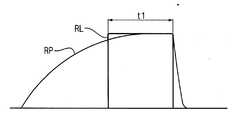
일반적으로, 액정표시패널(140)에 포함된 액정층은 데이터 라인(DL)들로 인가되는 데이터 전압에 응답하여 광의 투과율을 제어한다. 액정표시패널(140)에 포함된 액정층은 도 4에 도시된 바와 같이, 액정층이 구동되기 시작한 시점부터 구동이 끝나는 시점까지 액정의 응답 속도로 인하여 증가하는 응답 파형(RP)을 갖는다. 이때, 액정층의 응답 파형(RP)과 발광 유닛(152)의 발광 시간이 겹치는 영역의 넓이가 액정표시패널(140)을 투과하는 광의 휘도에 해당된다.In general, the liquid crystal layer included in the liquid
또한, 액정표시패널(140)은 첫 번째 게이트 라인으로부터 마지막 게이트 라인까지 순차적으로 구동됨에 따라, 액정층의 응답 파형(RP)은 1번째 발광 유닛(B1)에 대응되는 영역으로부터 8번째 발광 유닛(B8)에 대응되는 영역으로갈수록 구동 시점이 일정 시간만큼 늦어지는 형태를 갖는다.In addition, as the liquid
한편, 발광 유닛(152)들은 투과율 투과율 향상을 위하여, 액정층의 응답 파형(RP)과 동기되도록 구동된다. 즉, 발광 유닛(152)들은 1번째 발광 유닛(B1)으로부터 8번째 발광 유닛(B8)으로갈수록 액정층의 응답 파형(RP)이 지연되는 시간 만큼 지연되어 순차적으로 구동된다.On the other hand, the
도 3 및 도 4를 참조하면, 1번째 발광 유닛(B1)은 각각의 필드(F1, F2, F3)에 대응하여 제1 시간(t1) 동안 서로 다른 색의 광을 발생한다. 예를 들어, 1번째 발광 유닛(B1)은 제1 필드(F1)에서 적색 광(RL)을 발생하며, 제2 필드(F2)에서 녹색 광(GL)을 발생하며, 제3 필드(F3)에서 청색 광(BL)을 발생한다. 그러나, 적색 광(RL), 녹색 광(GL) 및 청색 광(BL)의 발광 순서는 다양하게 변경될 수 있다.3 and 4, the first light emitting unit B1 generates light of different colors during the first time t1 corresponding to each of the fields F1, F2, and F3. For example, the first light emitting unit B1 generates red light RL in the first field F1, generates green light GL in the second field F2, and generates a third field F3. Generates blue light BL. However, the light emission order of the red light RL, the green light GL, and the blue light BL may be changed in various ways.
도 3 및 도 5를 참조하면, 2번째 발광 유닛(B2) 내지 7번째 발광 유닛(B7)은 1번째 발광 유닛(B1)의 발광 개시 시점에 비하여 일정한 시간 만큼씩 순차적으로 지연되어 발광이 시작되며, 1번째 발광 유닛(B1)의 제1 시간(t1)에 보다 짧은 제2 시간(t2) 동안 광을 발생한다.3 and 5, the second light emitting unit B2 to the seventh light emitting unit B7 are sequentially delayed by a predetermined time as compared to the start point of light emission of the first light emitting unit B1 and light emission starts. The light is generated for a shorter second time t2 at the first time t1 of the first light emitting unit B1.
8번째 발광 유닛(B8)은 1번째 발광 유닛(B1)과 실질적으로 동일한 제1 시간(t1) 동안 광을 발생한다.The eighth light emitting unit B8 generates light for a first time t1 that is substantially the same as the first light emitting unit B1.
일 예로, 액정표시장치(100)가 60㎐로 구동될 경우, 한 프레임(FRAME)은 약 16.7㎳이며, 제1 내지 제3 필드(F1, F2, F3)은 각각 약 5.6㎳로 시분할된다. 이때, 2번째 내지 7번째 발광 유닛(B2 ... B7)은 약 2.1㎳ ~ 약 2.3㎳ 동안 광을 발생하며, 1번째 및 8번째 발광 유닛(B1, B8)은 약 2.4㎳ ~ 약 2.6㎳ 동안 광을 발생 한다.For example, when the
이와 같이, 최외각에 배치된 1번째 발광 유닛(B1) 및 8번째 발광 유닛(B8)의 발광 시간을 중앙부에 배치된 2번째 발광 유닛(B2) 내지 7번째 발광 유닛(B7)의 발광 시간에 비하여 증가시킴으로써, 휘도 균일성을 향상시킬 수 있다.Thus, the light emission time of the 1st light emitting unit B1 and the 8th light emitting unit B8 arrange | positioned at the outermost part is set to the light emission time of the 2nd light emitting unit B2-7th light emitting unit B7 arrange | positioned at the center part. By increasing in comparison, luminance uniformity can be improved.
한편, 발광 유닛(152)들은 중앙부로부터 가장자리로 갈수록 발광 시간이 점차적으로 증가되도록 구동될 수 있다. 예를 들어, 4번째 발광 유닛(B4) 및 5번째 발광 유닛(B5)은 가장 짧은 시간 동안 광을 발생하는 반면, 3번째 발광 유닛(B3)으로부터 1번째 발광 유닛(B1)으로갈수록 발광 시간이 점차적으로 증가되고, 6번째 발광 유닛(B6)으로부터 8번째 발광 유닛(B8)으로갈수록 발광 시간이 점차적으로 증가되도록 구동될 수 있다. 또한, 3번째 발광 유닛(B3) 내지 6번째 발광 유닛(B6)은 가장 짧은 시간 동안 광을 발생하는 반면, 2번째 발광 유닛(B2)으로부터 1번째 발광 유닛(B1)으로갈수록 발광 시간이 점차적으로 증가되고, 7번째 발광 유닛(B7)으로부터 8번째 발광 유닛(B8)으로갈수록 발광 시간이 점차적으로 증가되도록 구동될 수 있다.On the other hand, the
도 6은 본 발명의 다른 실시예에 따른 발광 유닛의 구동 방법을 나타낸 타이밍도이다.6 is a timing diagram illustrating a method of driving a light emitting unit according to another exemplary embodiment of the present invention.
도 1, 도 2 및 도 6을 참조하면, 액정표시장치(100)의 한 프레임(FRAME)은 4개의 필드(F1, F2, F3, F4)로 시분할되어 구동된다.1, 2, and 6, one frame FRAME of the
발광 유닛(152)들은 각 필드(F1, F2, F3, F4)에 대응하여 서로 다른 색의 광을 발생한다. 예를 들어, 발광 유닛(152)들은 제1 필드(F1)에 대응하여 적색 광(RL)을 발생하며, 제2 필드(F2)에 대응하여 녹색 광(GL)을 발생하며, 제3 필드(F3)에 대응하여 청색 광(BL)을 발생하며, 제4 필드(F4)에 대응하여 백색 광(WL)을 발생한다. 그러나, 적색 광(RL), 녹색 광(GL), 청색 광(BL) 및 백색 광(WL)의 발광 순서는 다양하게 변형될 수 있다.The
발광 유닛(152)들은 적색 광(RL), 녹색 광(GL) 및 청색 광(BL)의 발광을 위하여, 적색 발광다이오드(153a), 녹색 발광다이오드(153b) 및 청색 발광다이오드(153c)를 포함한다. 발광 유닛(152)들은 적색 발광다이오드(153a), 녹색 발광다이오드(153b) 및 청색 발광다이오드(153c)를 동시에 발광시키는 방법으로 백색 광(WL)을 구현할 수 있다. 이와 달리, 발광 유닛(152)들은 백색 광(WL)을 발생하는 백색 발광다이오드를 더 포함할 수도 있다.The
한편, 발광 유닛(152)들은 한 프레임(FRAME)을 3개의 필드로 시분할하는 대신, 4개의 필드로 시분할하여 구동한다는 점을 제외하고는 도3에 도시된 방법과 동일한 방법으로 구동된다. 즉, 가장자리에 배치된 1번째 발광 유닛(B1) 및 8번째 발광 유닛(B8)은 중앙에 배치된 2번째 발광 유닛(B2) 내지 7번째 발광 유닛(B7)에 비하여 발광 시간이 길게 구동된다. 이와 관련된 상세한 내용은 앞서 설명된 바 있으므로 생략하기로 한다.On the other hand, the
도 7은 본 발명의 다른 실시예에 따른 발광 유닛들을 나타낸 평면도이다.7 is a plan view illustrating light emitting units according to another exemplary embodiment of the present invention.
도 7을 참조하면, 본 발명의 다른 실시예에 따른 발광 유닛(252)들은 게이트 라인(GL)들의 배열 방향을 따라 복수가 일정한 간격으로 배치된다. 일 예로, 발광 유닛(252)들은 8개가 배치된다.Referring to FIG. 7, a plurality of light emitting
각각의 발광 유닛(252)은 한 프레임 동안 일정한 시간 간격으로 동일한 시간 동안 서로 다른 색의 광을 발생한다. 예를 들어, 발광 유닛(252)은 한 프레임 동안 일정한 시간 간격으로 적색 광, 녹색 광 및 청색 광을 순차적으로 발생한다. 이와 달리, 발광 유닛(252)은 한 프레임 동안 일정한 시간 간격으로 적색 광, 녹색 광, 청색 광 및 백색 광을 순차적으로 발생할 수 있다.Each
발광 유닛(252)은 광의 발생을 위하여 복수의 발광 소자(253)들을 포함한다. 예를 들어, 발광 소자(253)들은 적색 광을 발생하는 적색 발광 다이오드(253a), 녹색 광을 발생하는 녹색 발광 다이오드(253b) 및 청색 광을 발생하는 청색 발광 다이오드(253c)를 포함한다.The
발광 유닛(252)들은 모두 동일한 시간 동안 광을 발생한다. 반면, 발광 유닛(252)들 중 일부는 휘도 균일성을 향상시키기 위하여 나머지 발광 유닛(252)들에 비하여 많은 개수의 발광 소자(253)들을 갖는다. 즉, 가장자리에 인접하게 배치된 발광 유닛(252)들은 중앙부에 배치된 발광 유닛(252)들에 비하여 많은 개수의 발광 소자(253)들을 포함한다.The
구체적으로, 최외각에 배치된 1번째 발광 유닛(B1) 및 8번째 발광 유닛(B8)은 2번째 발광 유닛(B2) 내지 7번째 발광 유닛(B7)에 비하여 많은 개수의 발광 소자(253)들을 포함한다. 따라서, 1번째 발광 유닛(B1) 및 8번째 발광 유닛(B8)에서 발생되는 광량은 2번째 발광 유닛(B2) 내지 7번째 발광 유닛(B7)들에 비하여 상대적으로 증가되며, 실질적으로 액정표시패널(140)에는 전체적으로 균일한 광량이 도달하게 되어 휘도 균일성이 향상된다.In detail, the first light emitting unit B1 and the eighth light emitting unit B8 disposed at the outermost portion may have a larger number of
한편, 발광 유닛(252)들은 중앙부로부터 가장자리로갈수록 발광 소자(253)들의 개수가 점차적으로 증가되도록 형성될 수 있다. 예를 들어, 4번째 발광 유닛(B4) 및 5번째 발광 유닛(B5)은 가장 적은 개수의 발광 소자(253)들을 포함하는 반면, 3번째 발광 유닛(B3)으로부터 1번째 발광 유닛(B1)으로갈수록 발광 소자(253)들의 개수가 점차적으로 증가되고, 6번째 발광 유닛(B6)으로부터 8번째 발광 유닛(B8)으로갈수록 발광 소자(253)들의 개수가 점차적으로 증가되도록 형성될 수 있다. 또한, 3번째 발광 유닛(B3) 내지 6번째 발광 유닛(B6)은 가장 적은 개수의 발광 소자(253)들을 포함하는 반면, 2번째 발광 유닛(B2)으로부터 1번째 발광 유닛(B1)으로갈수록 발광 소자(253)들의 개수가 점차적으로 증가되고, 7번째 발광 유닛(B7)으로부터 8번째 발광 유닛(B8)으로갈수록 발광 소자(253)들의 개수가 점차적으로 증가되도록 형성될 수 있다.On the other hand, the
이와 같은 액정표시장치에 따르면, 중앙부에 비하여 휘도가 상대적으로 낮은 가장자리에 배치된 발광 유닛들의 발광 시간을 상대적으로 길게 구동함으로써, 휘도 균일성을 향상시킬 수 있다.According to such a liquid crystal display device, luminance uniformity can be improved by driving the light emission time of the light emitting units disposed at the edge of which the luminance is relatively lower than that of the central portion.
또한, 가장자리에 배치된 발광 유닛들은 중앙부에 배치된 발광 유닛들에 비하여 많은 개수의 발광 소자들을 포함함으로써, 휘도 균일성을 향상시킬 수 있다.In addition, the light emitting units disposed at the edges may include a greater number of light emitting elements than the light emitting units disposed at the center portion, thereby improving luminance uniformity.
앞서 설명한 본 발명의 상세한 설명에서는 본 발명의 바람직한 실시예들을 참조하여 설명하였지만, 해당 기술분야의 숙련된 당업자 또는 해당 기술분야에 통상의 지식을 갖는 자라면 후술될 특허청구범위에 기재된 본 발명의 사상 및 기술 영역으로부터 벗어나지 않는 범위 내에서 본 발명을 다양하게 수정 및 변경시킬 수 있음을 이해할 수 있을 것이다.In the detailed description of the present invention described above with reference to the preferred embodiments of the present invention, those skilled in the art or those skilled in the art having ordinary skill in the art will be described in the claims to be described later It will be understood that various modifications and variations can be made in the present invention without departing from the scope of the present invention.
Claims (16)
Translated fromKoreanPriority Applications (6)
| Application Number | Priority Date | Filing Date | Title |
|---|---|---|---|
| KR1020060031365AKR20070099942A (en) | 2006-04-06 | 2006-04-06 | LCD Display |
| CN200710079139XACN101051129B (en) | 2006-04-06 | 2007-02-14 | Liquid crystal display apparatus |
| JP2007052187AJP5148135B2 (en) | 2006-04-06 | 2007-03-02 | Liquid crystal display |
| EP10013691AEP2287830A1 (en) | 2006-04-06 | 2007-03-26 | Liquid crystal display apparatus |
| EP07006153AEP1843319A3 (en) | 2006-04-06 | 2007-03-26 | Liquid crystal display apparatus |
| US11/696,645US8059083B2 (en) | 2006-04-06 | 2007-04-04 | Liquid crystal display apparatus |
Applications Claiming Priority (1)
| Application Number | Priority Date | Filing Date | Title |
|---|---|---|---|
| KR1020060031365AKR20070099942A (en) | 2006-04-06 | 2006-04-06 | LCD Display |
Publications (1)
| Publication Number | Publication Date |
|---|---|
| KR20070099942Atrue KR20070099942A (en) | 2007-10-10 |
Family
ID=37986823
Family Applications (1)
| Application Number | Title | Priority Date | Filing Date |
|---|---|---|---|
| KR1020060031365ACeasedKR20070099942A (en) | 2006-04-06 | 2006-04-06 | LCD Display |
Country Status (5)
| Country | Link |
|---|---|
| US (1) | US8059083B2 (en) |
| EP (2) | EP1843319A3 (en) |
| JP (1) | JP5148135B2 (en) |
| KR (1) | KR20070099942A (en) |
| CN (1) | CN101051129B (en) |
Cited By (1)
| Publication number | Priority date | Publication date | Assignee | Title |
|---|---|---|---|---|
| KR20110040509A (en)* | 2009-10-14 | 2011-04-20 | 엘지디스플레이 주식회사 | Backlight unit, LCD including same and driving method thereof |
Families Citing this family (11)
| Publication number | Priority date | Publication date | Assignee | Title |
|---|---|---|---|---|
| WO2009082739A1 (en)* | 2007-12-20 | 2009-07-02 | Real D | Intra-pixel illumination system and methods |
| JP5540564B2 (en)* | 2009-05-18 | 2014-07-02 | セイコーエプソン株式会社 | Electro-optical device and electronic apparatus |
| JP5249899B2 (en)* | 2009-09-30 | 2013-07-31 | シャープ株式会社 | Liquid crystal display |
| US9019445B2 (en) | 2009-12-25 | 2015-04-28 | Sharp Kabushiki Kaisha | Lighting device, display device, and television receiver |
| US20110157260A1 (en)* | 2009-12-30 | 2011-06-30 | Jayoung Pyun | 3d image display device |
| KR101039608B1 (en)* | 2010-05-04 | 2011-06-09 | 엘지이노텍 주식회사 | Backlight Unit and Display Device |
| JP2013152862A (en)* | 2012-01-25 | 2013-08-08 | Sharp Corp | Lighting device and display device having the same |
| KR102091197B1 (en)* | 2012-12-18 | 2020-03-18 | 엘지디스플레이 주식회사 | Apparatus for driving a light emitting diode array and liquid crystal display device using the same |
| TWI489098B (en)* | 2014-03-11 | 2015-06-21 | Utechzone Co Ltd | Defect detection method and defect detection device |
| CN107799507B (en)* | 2016-08-29 | 2020-02-04 | 鸿富锦精密工业(深圳)有限公司 | Backlight system and method for manufacturing the same |
| JP2023048725A (en) | 2021-09-28 | 2023-04-07 | 日亜化学工業株式会社 | Image display method and image display device |
Family Cites Families (16)
| Publication number | Priority date | Publication date | Assignee | Title |
|---|---|---|---|---|
| JP3796588B2 (en)* | 1995-02-09 | 2006-07-12 | 株式会社リコー | Image forming apparatus |
| US7088333B1 (en)* | 1999-03-12 | 2006-08-08 | Matsushita Electric Industrial Co., Ltd. | Surface lighting device and portable terminal using the same |
| JP2002075038A (en)* | 2000-09-05 | 2002-03-15 | Sony Corp | Back light unit and liquid-crystal display device using it |
| US6585395B2 (en)* | 2001-03-22 | 2003-07-01 | Altman Stage Lighting Co., Inc. | Variable beam light emitting diode light source system |
| US7030848B2 (en) | 2001-03-30 | 2006-04-18 | Matsushita Electric Industrial Co., Ltd. | Liquid crystal display |
| US7040794B2 (en)* | 2001-07-12 | 2006-05-09 | Northrop Grumman Corporation | Programmable multi-color backlight for a liquid crystal display |
| JP3850241B2 (en)* | 2001-07-19 | 2006-11-29 | シャープ株式会社 | LIGHTING DEVICE AND LIQUID CRYSTAL DISPLAY DEVICE USING THE SAME |
| JP2003233352A (en)* | 2002-02-07 | 2003-08-22 | Matsushita Electric Ind Co Ltd | Liquid crystal display |
| JP2003331604A (en)* | 2002-05-16 | 2003-11-21 | Harison Toshiba Lighting Corp | Backlight unit |
| WO2004038283A1 (en)* | 2002-10-22 | 2004-05-06 | Sharp Kabushiki Kaisha | Backlight unit and liquid crystal display unit using backlight unit |
| TWI308239B (en)* | 2002-10-25 | 2009-04-01 | Toppoly Optoelectronics Corp | Light module and flat panel display including the light module |
| JP4493274B2 (en)* | 2003-01-29 | 2010-06-30 | 富士通株式会社 | Display device and display method |
| KR100855957B1 (en) | 2004-02-09 | 2008-09-02 | 삼성전자주식회사 | Solid-state image sensor and its driving method for compensating the brightness of the periphery of the screen |
| US7737937B2 (en)* | 2004-05-14 | 2010-06-15 | Koninklijke Philips Electronics N.V. | Scanning backlight for a matrix display |
| KR100586968B1 (en)* | 2004-05-28 | 2006-06-08 | 삼성전기주식회사 | LED Package and Backlight Assembly for LCD |
| CN100353240C (en)* | 2005-07-25 | 2007-12-05 | 友达光电股份有限公司 | Direct Type Backlight |
- 2006
- 2006-04-06KRKR1020060031365Apatent/KR20070099942A/ennot_activeCeased
- 2007
- 2007-02-14CNCN200710079139XApatent/CN101051129B/ennot_activeExpired - Fee Related
- 2007-03-02JPJP2007052187Apatent/JP5148135B2/ennot_activeExpired - Fee Related
- 2007-03-26EPEP07006153Apatent/EP1843319A3/ennot_activeWithdrawn
- 2007-03-26EPEP10013691Apatent/EP2287830A1/ennot_activeCeased
- 2007-04-04USUS11/696,645patent/US8059083B2/ennot_activeExpired - Fee Related
Cited By (1)
| Publication number | Priority date | Publication date | Assignee | Title |
|---|---|---|---|---|
| KR20110040509A (en)* | 2009-10-14 | 2011-04-20 | 엘지디스플레이 주식회사 | Backlight unit, LCD including same and driving method thereof |
Also Published As
| Publication number | Publication date |
|---|---|
| CN101051129A (en) | 2007-10-10 |
| JP5148135B2 (en) | 2013-02-20 |
| US8059083B2 (en) | 2011-11-15 |
| EP1843319A3 (en) | 2009-10-14 |
| EP2287830A1 (en) | 2011-02-23 |
| CN101051129B (en) | 2011-07-20 |
| JP2007279698A (en) | 2007-10-25 |
| EP1843319A2 (en) | 2007-10-10 |
| US20070236446A1 (en) | 2007-10-11 |
Similar Documents
| Publication | Publication Date | Title |
|---|---|---|
| KR20070099942A (en) | LCD Display | |
| KR101029432B1 (en) | Driving Method and Driving Device of Liquid Crystal Display | |
| US7928970B2 (en) | Display device and control method thereof | |
| TWI390495B (en) | Color sequential backlight liquid crystal displays and related methods | |
| JP4593257B2 (en) | LIGHTING DEVICE, LIQUID CRYSTAL DISPLAY DEVICE, PORTABLE TERMINAL DEVICE AND CONTROL METHOD THEREOF | |
| JP2008249780A (en) | Liquid crystal display device | |
| KR20030096904A (en) | Liquid crystal display for performing time divisional color display, method of driving the same and backlight unit for liquid crystal display | |
| WO2007066435A1 (en) | Illumination device and display apparatus provided with the same | |
| KR20080056390A (en) | Scanning backlight type liquid crystal display device and driving method thereof | |
| US7764267B2 (en) | Liquid crystal display apparatus and method of driving the same | |
| CN100470333C (en) | Backlight unit, display device having the same, and method for controlling light source | |
| JP7222835B2 (en) | Display device | |
| US20100149086A1 (en) | Liquid crystal display device | |
| TW201621423A (en) | Display device and method of driving the same | |
| JP2010266746A (en) | Liquid crystal display | |
| KR101249248B1 (en) | Liquid crystal display apparatus and mathod of driving thereof | |
| US9601066B2 (en) | Field sequential display including primary color sub-pixels, a transparent sub-pixel, and differently-colored light sources | |
| US12067950B2 (en) | Display device | |
| KR100658674B1 (en) | Backlight driving circuit | |
| KR20080054507A (en) | Backlight assembly, driving method thereof and display device having same | |
| KR20070109395A (en) | LCD Display | |
| KR20070073713A (en) | Backlight unit and display device including same | |
| KR20090019237A (en) | Backlight assembly, display device having same, driving method of backlight assembly and driving method of display device | |
| KR20080003560A (en) | Backlight and its driving method and liquid crystal display including the same | |
| KR101723455B1 (en) | Color filter substrate and liquid crystal display device including thereof |
Legal Events
| Date | Code | Title | Description |
|---|---|---|---|
| PA0109 | Patent application | Patent event code:PA01091R01D Comment text:Patent Application Patent event date:20060406 | |
| PG1501 | Laying open of application | ||
| A201 | Request for examination | ||
| PA0201 | Request for examination | Patent event code:PA02012R01D Patent event date:20110406 Comment text:Request for Examination of Application Patent event code:PA02011R01I Patent event date:20060406 Comment text:Patent Application | |
| E902 | Notification of reason for refusal | ||
| PE0902 | Notice of grounds for rejection | Comment text:Notification of reason for refusal Patent event date:20120619 Patent event code:PE09021S01D | |
| N231 | Notification of change of applicant | ||
| PN2301 | Change of applicant | Patent event date:20120913 Comment text:Notification of Change of Applicant Patent event code:PN23011R01D | |
| E601 | Decision to refuse application | ||
| PE0601 | Decision on rejection of patent | Patent event date:20121101 Comment text:Decision to Refuse Application Patent event code:PE06012S01D Patent event date:20120619 Comment text:Notification of reason for refusal Patent event code:PE06011S01I |