KR20070099282A - Captured video object-adaptive screen output system and method - Google Patents
Captured video object-adaptive screen output system and methodDownload PDFInfo
- Publication number
- KR20070099282A KR20070099282AKR1020060030537AKR20060030537AKR20070099282AKR 20070099282 AKR20070099282 AKR 20070099282AKR 1020060030537 AKR1020060030537 AKR 1020060030537AKR 20060030537 AKR20060030537 AKR 20060030537AKR 20070099282 AKR20070099282 AKR 20070099282A
- Authority
- KR
- South Korea
- Prior art keywords
- image
- output
- display unit
- unit
- screen
- Prior art date
- Legal status (The legal status is an assumption and is not a legal conclusion. Google has not performed a legal analysis and makes no representation as to the accuracy of the status listed.)
- Ceased
Links
Images

Classifications
- G—PHYSICS
- G06—COMPUTING OR CALCULATING; COUNTING
- G06T—IMAGE DATA PROCESSING OR GENERATION, IN GENERAL
- G06T13/00—Animation
- G06T13/80—2D [Two Dimensional] animation, e.g. using sprites
- G—PHYSICS
- G06—COMPUTING OR CALCULATING; COUNTING
- G06T—IMAGE DATA PROCESSING OR GENERATION, IN GENERAL
- G06T7/00—Image analysis
- G06T7/10—Segmentation; Edge detection
- G06T7/11—Region-based segmentation
- G—PHYSICS
- G06—COMPUTING OR CALCULATING; COUNTING
- G06T—IMAGE DATA PROCESSING OR GENERATION, IN GENERAL
- G06T7/00—Image analysis
- G06T7/20—Analysis of motion
- G06T7/246—Analysis of motion using feature-based methods, e.g. the tracking of corners or segments
- G06T7/248—Analysis of motion using feature-based methods, e.g. the tracking of corners or segments involving reference images or patches
Landscapes
- Engineering & Computer Science (AREA)
- Physics & Mathematics (AREA)
- General Physics & Mathematics (AREA)
- Theoretical Computer Science (AREA)
- Computer Vision & Pattern Recognition (AREA)
- Multimedia (AREA)
- Controls And Circuits For Display Device (AREA)
Abstract
Translated fromKoreanDescription
Translated fromKorean도 1은 본원 발명의 촬상 영상 객체 대응 화면 출력 시스템의 구성을 나타내는 도면이고,1 is a diagram showing the configuration of a captured image object-compatible screen output system of the present invention;
도 2는 본원 발명의 촬상 영상 객체 대응 화면 출력 방법의 상세 처리과정을 나타내는 순서도이며,2 is a flowchart illustrating a detailed process of a method for outputting a captured image object-corresponding screen according to the present invention;
도 3은 가상스크린(131)의 셀 분할을 나타내는 도면이고,3 is a diagram illustrating cell division of the
도 4는 촬상부(120)의 촬상 영상 이미지 중 이미지 객체를 추출하는 과정을 나타내는 도면이고,4 is a diagram illustrating a process of extracting an image object from the captured image of the
도 5 및 도 6은 추출된 이미지 객체에 따라 변화되어 출력되는 표시부 출력 영상의 일 예를 나타내는 도면이다.5 and 6 are diagrams illustrating an example of a display unit output image which is changed and output according to the extracted image object.
도 7은 본원발명의 촬상 영상 객체 대응 화면 출력 시스템의 일 실시예를 나타내는 도면이다.FIG. 7 is a diagram illustrating an embodiment of a system for outputting a captured image object corresponding to the present invention. FIG.
* 도면의 주요 부호에 대한 설명 *Description of the main symbols in the drawings
100: 촬상 영상 객체 대응 화면 출력 시스템100: screen output system corresponding to the captured image object
110: 표시부120: 촬상부110: display unit 120: imaging unit
130: 영상객체반응부140: 저장부130: image object reaction unit 140: storage unit
131: 가상스크린132: 독립셀131: virtual screen 132: independent cell
10: 촬상 대상 영상 이미지11: 촬상 대상 영상 이미지 데이터 값10: Capture target image image 11: Capture target image image data value
20: 이미지 객체20: image object
120': 카메라130': 컴퓨터120 ': camera 130': computer
140': LCD140 ': LCD
본원 발명은 촬상 영상의 움직임에 반응하는 화면 출력에 관한 것으로서, 더욱 상세하게는, 표시부 출력 영상에 대한 표시부 이외의 다른 영상 객체의 촬상이 감지되는 경우 촬상이 감지된 영상 객체에 대응하여 표시부 출력화면을 변경하여 출력할 수 있도록 하는 촬상 영상 객체 대응 화면 출력 시스템 및 그 방법에 관한 것이다.The present invention relates to a screen output in response to the movement of the captured image, and more particularly, when the imaging of the image object other than the display unit for the display unit output image is detected, the display unit output screen corresponding to the image object is detected The present invention relates to a screen output system corresponding to a captured image object and to output the same.
일반적으로 가상현실 체험을 위한 시뮬레이션 장치 등의 경우 사용자의 움직임을 인식하여 이에 대응되는 영상 출력 화면을 출력하는 것에 의해 사용자의 시각적 시뮬레이션 효과를 충족시키고 나아가 사용자의 다른 행동을 유도하도록 설정되는 것이 일반적이다.In general, in the case of a simulation device for a virtual reality experience, it is generally set to satisfy a user's visual simulation effect and further induce other actions by recognizing a user's movement and outputting an image output screen corresponding thereto. .
상술한 바와 같은 시뮬레이션 장치 등에서와 같이 사용자와 영상이 서로 상 호 작용할 수 있도록 하기 위해서는 사용자의 움직임을 식별하고 검출할 수 있는 수단이 필요하게 된다. 이러한 필요성에 따라 사용자의 움직임을 감지하기 위한 수단으로서 모션캡쳐(motion capture) 방식이 널리 사용되고 있다.As described above, in order to enable the user and the image to interact with each other, a means for identifying and detecting the user's movement is required. In accordance with this need, a motion capture method is widely used as a means for detecting a user's movement.
그러나 상술한 모션캡쳐 방식은 대부분 인체에 마커 또는 센서를 붙인 다음 카메라로 마커 영상이나, 센서로부터 나온 데이터를 분석해 인체 각 관절들의 위치와 방향 등을 측정한다. 여기에 사용된 마커 또는 센서의 작동 방식에 따라 초음파(acoustic), 보철(prosthetics), 자기(magnetic), 광학(optical) 방식의 네 가지로 구분된다.However, most of the motion capture methods described above attach a marker or sensor to a human body and then measure the position and direction of each joint of the human body by analyzing the marker image or data from the sensor with a camera. According to the method of operation of the marker or sensor used here, it is classified into four types: ultrasonic, prosthetics, magnetic, and optical.
먼저, 초음파방식의 모션캡쳐 시스템은 다수의 초음파를 발생하는 센서와 3개의 초음파 수신부로 구성되고, 연기자의 각 관절에 부착된 초음파 센서들은 순차적으로 초음파를 발생하고, 그 초음파가 수신장치에 수신되기까지 걸린 시간을 이용해서 센서에서 수신부까지의 거리를 계산한다. 각 센서들의 3차원 공간상 위치는 3개의 수신부에서 각각 계산된 값을 이용한 삼각 측정원리에 의해 구할 수 있다.First, the ultrasonic motion capture system is composed of a sensor generating a plurality of ultrasonic waves and three ultrasonic receivers, the ultrasonic sensors attached to each joint of the performer sequentially generates ultrasonic waves, the ultrasonic waves are received by the receiver Using the time taken to calculate the distance from the sensor to the receiver. The three-dimensional position of each sensor can be obtained by the triangulation principle using the values calculated at each of the three receivers.
그러나 이 방식은 환경의 간섭을 별로 받지 않고 위치측정에 필요한 계산량이 적어 실시간 처리가 가능하며 값이 싸다는 장점이 있으나, 샘플링 빈도가 높지 않고 동시에 사용할 수 있는 초음파 발생장치의 수가 많지 않다는 문제점이 있다.However, this method has the advantage that it can be processed in real time because of the small amount of calculation required for location measurement without receiving much interference from the environment, but it is inexpensive. .
또한, 센서가 크기 때문에 연기자의 동작이 부자연스러워질 수 있고, 음향장치의 특성상 초음파의 반사에 의한 영향을 많이 받는다는 문제점이 있다.In addition, since the sensor is large, the actor's operation may be unnatural, and there is a problem in that it is affected by the reflection of the ultrasonic wave due to the characteristics of the acoustic device.
한편, 보철방식의 모션캡쳐 시스템은 연기자의 관절 움직임을 측정하기 위한 전위차계와 슬라이더로 이루어진 복합체로 구성되는데, 수신장치를 갖지 않기 때문 에 다른 환경의 간섭이나 영향을 받지 않는 장치이다. 따라서, 초기 세트업 과정이 필요 없으며 고가의 스튜디오 환경설비도 필요 없다. 특히, 이 방식은 매우 높은 샘플링 빈도로 모션 데이터를 획득할 수 있다는 장점이 있다. 그러나, 이 방식은 부담스러운 기계장치를 연기자의 몸에 부착하여야 하므로 동작이 부자연스러워 질 수 있고, 보철장치가 연기자의 각 관절에 얼마나 정확하게 위치했는지에 따라 정확도가 달라진다는 문제점이 발생한다.On the other hand, the prosthetic motion capturing system is composed of a complex consisting of a slider and a potentiometer for measuring the joint movement of the performer, because it does not have a receiver is a device that is not affected by interference or other environments. Therefore, no initial set-up process is required and no expensive studio environmental equipment is required. In particular, this method has the advantage that motion data can be obtained with a very high sampling frequency. However, this method requires a burdensome mechanism to be attached to the performer's body, which may result in unnatural operation, and the accuracy of the prosthetic device may vary depending on how precisely the prosthetic device is positioned at each joint of the performer.
또한, 자기방식의 모션캡쳐 시스템은 연기자의 각 관절부위에 자기장을 계측할 수 있는 센서를 부착하고 자기장 발생장치 근처에서 연기자가 움직일 때 각 센서에서 측정되는 자기장의 변화를 다시 공간적인 변화량으로 계산하여 움직임을 측정하는 방식이다. 이 방식은 저렴한 가격으로 장치의 구현이 가능하고 실시간 처리가 가능하다는 장점이 있다.In addition, the magnetic motion capture system attaches a sensor to measure the magnetic field at each joint of the performer, and calculates the change in the magnetic field measured by each sensor as a spatial change amount when the actor moves near the magnetic field generating device. It is a way of measuring movement. This method has the advantage that the device can be implemented at a low price and real time processing is possible.
그러나 이 방식에서 유선방식의 센서를 사용하는 경우에는 센서로부터 연결된 케이블들로 인해 연기자의 동작에 제한을 주고, 이것으로 인해 복잡하고 빠른 움직임을 자연스럽게 표현하는 것을 어렵게 하는 문제점이 있다. 또한, 무선방식의 센서를 사용하는 경우에도 연기자의 몸에 송신기를 부착하여야 하며, 자기장 영역 안에서만 가능하므로 동작반경이 제한되는 문제점이 있다.However, in the case of using a wired sensor in this method, there is a problem in that it restricts the actor's operation due to the cables connected from the sensor, which makes it difficult to express complex and fast movements naturally. In addition, even in the case of using a wireless sensor, the transmitter must be attached to the actor's body, and the operation radius is limited because it is possible only in the magnetic field region.
광학방식의 모션캡쳐 시스템은 연기자의 주요 관절부분에 적외선을 반사하는 반사마커(reflective marker)들을 부착하고, 2내지 16대의 적외선 필터가 부착된 카메라를 이용해 반사되는 마커들의 좌표를 생성한다. 여러대의 카메라로 캡쳐한 2차원 좌표는 전용 프로그램으로 분석되어 3차원 공간상 좌표로 계산된 후 에니메이 션에 활용한다. 광학 방식 시스템의 장점 중 하나는 높은 샘플링 빈도를 들 수 있는데, 스포츠 선수의 동작과 같이 매우 빠른 움직임을 캡쳐할 때 유용하다. 또한, 연기자에 부착되는 마커의 크기가 작고 가벼워서 연기자가 자유롭게 모션을 표현할 수 있으며, 200개 이상의 마커를 처리할 수 있어서 다수 연기자의 모션을 동시에 캡쳐할 수 있는 효과가 있다.The optical motion capture system attaches reflective markers that reflect infrared light to the main joint of the performer, and generates coordinates of the reflected markers using a camera with 2 to 16 infrared filters. Two-dimensional coordinates captured by multiple cameras are analyzed by a dedicated program, calculated in coordinates in three-dimensional space, and used for animation. One of the advantages of the optical system is its high sampling frequency, which is useful when capturing very fast movements, such as the movement of a sports player. In addition, since the size of the marker attached to the actor is small and light, the actor can freely express the motion, and since 200 or more markers can be processed, there is an effect that can simultaneously capture the motion of multiple actors.
그러나 이 방식은 마커가 다른 물체에 의해 가려질 때 마커의 궤적을 잠시 잃어버리게 되어, 모션 데이터를 후 처리하는 과정이 필요하게 되기 때문에 실시간 모션캡쳐가 어렵게 되는 문제점이 있다.However, this method has a problem in that real-time motion capture becomes difficult because the trajectory of the marker is lost for a while when the marker is covered by another object, which requires post-processing motion data.
따라서, 본원 발명은 상술한 종래기술의 문제점을 해결하기 위한 것으로서, 표시부 출력 영상에 대한 표시부 이외의 다른 영상 객체의 촬상이 감지되는 경우 촬상이 감지된 영상 객체에 대응하여 표시부 출력화면을 변경하여 출력할 수 있도록 하는 촬상 영상 객체 대응 화면 출력 시스템 및 그 방법을 제공하는 것을 그 목적으로 한다.Accordingly, the present invention is to solve the above-described problems of the prior art, and when the imaging of the image object other than the display unit for the display unit output image is detected, the display unit output screen is changed and output in response to the image object is detected It is an object of the present invention to provide a captured image object-compatible screen output system and a method thereof.
상술한 목적을 달성하기 위한 본원 발명의 촬상 영상 객체 대응 화면 출력 시스템은, 출력대상 영상을 표시하는 표시부와; 상기 표시부의 출력 대상 영상 영역에 진입한 대상물을 촬영하는 촬상부와; 상기 표시부로 출력 영상 데이터를 출력 하며, 상기 촬상부의 출력영상 영역으로 진입한 대상물을 검출한 후 대상물에 따라 변형되는 기 설정된 출력 영상을 상기 표시부로 출력하는 영상객체반응부와; 상기 영상객체반응부의 출력 영상 데이터를 저장하는 저장부;를 포함하여 구성되는 것을 특징으로 한다.According to an aspect of the present invention, there is provided a system for outputting a captured image object corresponding screen, including: a display unit which displays an output target image; An imaging unit for photographing an object entering the output target image area of the display unit; An image object reaction unit configured to output output image data to the display unit, and detect a target object entering the output image region of the image pickup unit, and output a preset output image that is transformed according to the target object to the display unit; And a storage unit which stores the output image data of the image object response unit.
상기 표시부는 CRT, LCD, PDP, 또는 영상투사기와 스크린으로 구성되는 투영장치 중 어느 하나로 구성되는 것을 특징으로 한다.The display unit may be composed of any one of a CRT, an LCD, a PDP, or a projection device including an image projector and a screen.
상기 촬상부는 상기 표시부의 출력화면에 대응되는 영역을 촬상 대상 영상 영역으로 촬상하도록 설정되는 것을 특징으로 한다.The imaging unit may be set to capture an area corresponding to an output screen of the display unit as an imaging target image area.
상기 영상객체반응부는 상기 표시부 출력 영상을 매핑한 후 셀 영역으로 분할하여 각각의 셀 영역의 이미지 데이터 값을 저장하고, 상기 촬상부의 촬상 영상중 각각의 셀 영역에 대응되는 이미지 데이터 값을 각각의 셀 별로 기 저장된 이미지 데이터 값과 비교하여 변환된 셀 영역을 촬상된 이미지 객체로 추출하는 가상스크린을 구비한 것을 특징으로 한다.The image object reacting unit maps the output image of the display unit, divides the image into cell regions, stores image data values of each cell region, and stores image data values corresponding to each cell region in the captured image of the imaging unit. And a virtual screen for extracting the converted cell region as a picked-up image object by comparing with the previously stored image data value.
상술한 목적을 달성하기 위한 본원 발명의 촬상 영상 객체 대응 화면 출력 방법은, 표시부 출력영상 영역을 다수의 셀로 분할하여 각각의 셀의 이미지 데이터 값을 저장하는 셀분할과정과; 상기 표시부 출력 영상 영역을 촬상하도록 설정된 촬상부를 통해 입력되는 외부 입력영상을 상기 표시부 출력영상 영역에 투영한 후 상기 셀분할과정에서 저장된 각각의 셀별 이미지 데이터 값과 비교하여 셀 별 이미지 데이터 값의 변화가 발생한 셀 영역을 추출하는 것에 의해 이미지 객체를 추출하는 이미지 객체 추출과정과; 상기 이미지객체 추출과정에서 추출된 이미지 객체를 기준으로 하여 상기 표시부의 출력 영상을 변환하여 출력하는 표시부 영상 갱신과정;을 포함하여 구성되는 것을 특징으로 한다.According to an aspect of the present invention, there is provided a method of outputting a captured image object-corresponding screen according to an embodiment of the present invention, comprising: a cell division process of dividing a display unit output image region into a plurality of cells and storing image data values of each cell; After projecting the external input image inputted through the imager configured to capture the display output image area to the display output image area, the change of the image data value of each cell is compared with the image data value of each cell stored in the cell division process. An image object extraction step of extracting an image object by extracting the generated cell region; And a display unit image updating process of converting and outputting an output image of the display unit on the basis of the image object extracted in the image object extraction process.
상기 표시부 영상 갱신과정은 상기 갱신된 표시부 영상의 각각의 셀별 이미지 데이터 값을 저장하는 이미지 데이터 값 저장과정과;The display unit image updating process may include: an image data value storing process of storing image data values of respective cells of the updated display unit image;
상기 이미지 데이터 값 저장과정 이후 상기 이미지객체 추출과정으로 복귀하여 처리과정을 반복 수행하는 이미지객체추출 괘환과정;을 더 포함하여 이루어지는 것을 특징으로 한다.And an image object extracting step of returning to the image object extraction step and repeating the processing after the storing of the image data value.
이하, 첨부 도면을 참조하여 본원 발명을 더욱 상세히 설명한다.Hereinafter, the present invention will be described in more detail with reference to the accompanying drawings.
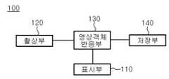
도 1은 본원 발명의 촬상 영상 객체 대응 화면 출력 시스템의 블록 구성도이다.1 is a block diagram of a system for outputting a captured image object corresponding screen of the present invention.
도 1에 도시된 바와 같이 본원 발명의 촬상 영상 객체 대응 화면 출력 시스템은, 출력대상 영상을 표시하는 표시부(110)와; 표시부(110)의 출력 대상 영상 영역에 진입한 대상물을 촬영하는 촬상부(120)와; 표시부(110)로 출력 영상 데이터를 출력하며, 촬상부(120)의 출력영상 영역으로 진입한 대상물을 검출한 후 대상물에 따라 변형되는 기 설정된 출력 영상을 표시부로 출력하는 영상객체반응부(130)와; 영상객체반응부의 출력 영상 데이터를 저장하는 저장부(140)를 포함하여 구성된다.As illustrated in FIG. 1, an image capturing system corresponding screen output system according to the present invention includes: a
상술한 구성에서 상기 표시부(110)는 CRT, LCD, PDP 등의 영상 출력장치로 구성되거나, 또는 영상투사기와 영상투사기의 출력 영상을 표시하는 스크린으로 구 성되는 투영장치의 스크린 영역으로 구성될 수 있다.In the above-described configuration, the
상술한 바와 같이 표시부(110)가 설정된 후에는 상기 촬상부(120)는 영상 출력 장치의 출력화면에 대응되는 영역, 또는, 영상투사기의 출력 영상을 표시하는 스크린 영역을 촬상 대상 영상 영역으로 촬상하도록 설정된다.As described above, after the
상기 영상객체반응부(130)는 표시부(110)의 출력 영상 영역을 다수의 셀 영역을 가지는 가상스크린에 매핑시킨 후, 각각의 셀 출력 영상의 이미지 데이터값을 저장한다. 이때, 이미지 데이터값은, RGB 혹은 YUV 등의 화소 데이터 값으로 설정될 수 있다. 이후 촬상부(120)의 촬상 영상을 입력받은 후 가상스크린에 매핑시켜서, 셀 출력 영상의 이미지 데이터 값의 변화를 검출한 후 이미지 데이터 값의 변화가 발생한 경우, 변화된 이미지 데이터 값을 가지는 셀들로 이루어지는 영상 객체를 추출한다. 영상 객체가 추출된 후에는 영상 객체에 따라 변화되도록 기설정된 출력 영상 데이터를 저장부(140)에서 읽어 들여 표시부(110) 에 출력하도록 동작한다. 이를 위하여 저장부(140)는 초기 출력 영상 데이터와, 촬상된 대상물의 영상 데이터에 반응하여 출력되도록 기 설정된 출력 영상 데이터를 저장한다.The image
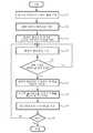
도 2는 본원 발명의 촬상 영상 객체 대응 화면 출력 방법의 상세 처리과정을 나타내는 순서도이며, 도 3은 가상스크린(131)을 이용한 셀 분할을 나타내는 도면이고, 도 4는 촬상부(120)의 촬상 영상 이미지 중 이미지 객체를 추출하는 과정을 나타내는 도면이고, 도 5 및 도 6은 추출된 이미지 객체에 따라 변화되어 출력되는 표시부 출력 영상의 일 예를 나타내는 도면이다.2 is a flowchart illustrating a detailed process of a method for outputting a captured image object-corresponding screen according to the present invention, FIG. 3 is a diagram illustrating cell division using a
도 1 내지 도 6을 참조하여 도 2의 본원 발명의 촬상 영상 객체 대응 화면 출력 방법의 처리과정을 상세히 설명하면 다음과 같다.Referring to Figures 1 to 6 will be described in detail the processing of the image output image corresponding screen output method of the present invention of FIG.
도 2에 도시된 바와 같이, 도 1의 영상객체반응부(130)는 먼저 표시부(110) 출력 영상 영역을 도 3의 가상스크린(131)에 매핑한 후 다수의 셀 영역으로 분할하고(S1), 분할된 각각의 셀 영역에 대한 RGB, YUV 등의 이미지 데이터 값을 저장한다(S2).As shown in FIG. 2, the image
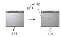
상술한 바와 같은 본원발명의 가상스크린(131)은 컴퓨터의 모니터 등의 화면 영역으로 설정될 수 있는 것으로서 가상적으로 표시부 영상 영역을 다수의 셀로 나누어 그 셀들을 화상 정보를 분석하고 추적하는 기본 단위로 사용한다. 일예로 본원발명의 촬상 영상 객체 대응 화면 출력 시스템이 구동되어 최초로 표시부 출력 영상 정보를 받으면, 영상 정보에서 자기가 위치한 부분의 RGB 컬러 값을 기본비교 변수로서 기억한다.As described above, the
도 3은 가상스크린(131)의 일 실시 예로서 가상스크린은 표시부의 출력 영상 영역과 정확히 대응되도록 매핑되며, 가로 32개, 세로 24 개(A, B, C ... ,X)의 셀로서 총768 개의 셀로 분할한 후 각각 자기 영역의 화상 변화를 체크 하도록 구현한 것으로 도시하였다. 도 3에서 독립셀(132)은 1열 J 행에 위치한 셀이며, 초기 RGB 컬러 값은 (196,196,204)으로 설정되는 것으로 하였다. 여기서, 상술한 도 3은 가상스크린의 일 예를 설명하는 것으로서 다양하게 변형 실시될 수 있는 것으로서 본원발명이 상술한 도 3의 셀 구성 조건에 의해 한정되는 것은 아니다.FIG. 3 illustrates an example of the
상술한 바와 같이 표시부 출력 영상 영역이 가상스크린에 의해 셀 영역으로 분리되고 각각의 셀에 대응되는 이미지 데이터 값이 저장된 후에는 촬상부 촬상 영역을 표시부(110) 출력 영상 영역에 매핑한다. 이 과정에서 촬상부(120)의 촬상 영역을 표시부(110)의 출력 영상 영역이 되도록 설정하는 것은 상술한 바와 같다. 즉, 이러한 구성은 컴퓨터의 모니터 영역을 가상스크린으로 설정하고, 촬상부는 컴퓨터의 모니터에 표시된 표시부 출력 영상 영역과 촬상 영역이 일치하도록 설정되는 것이 촬상부의 촬상 영역 설정의 일 예가 될 수 있다(S3).As described above, after the display unit output image region is separated into the cell region by the virtual screen and image data values corresponding to each cell are stored, the image capturer image capture region is mapped to the
이후 영상객체반응부(130)는 가상스크린을 이용하여 표시부(110)의 출력 영상을 분할한 각각의 셀의 이미지 데이터를 저장하고, 촬상부(120)의 촬상 영상 영역을 표시부 출력 영상 영역으로 매핑한 후 촬상부(120)로부터 계속하여 입력되는 촬상 영상을 수신한다. 일반적으로 영상객체반응부(130)가 수신하는 촬상부(120)의 촬상 영상은 초당 30프레임으로 하여 영상객체반응부(130)로 입력되도록 설정될 수 있다(S4).Thereafter, the image
S4과정에 의해 촬상부(120)로부터 촬상 영상을 수신한 영상객체반응부(130)는 수신된 촬상부 영상을 가상스크린(131) 상에 매핑한 후, 가상스크린(131)의 각 셀 별 이미지 데이터 값(RGB, YUV 등)이 변화되었는 지를 판단한다(S5).After receiving the captured image from the
S5 과정의 판단 결과 촬상부(120)의 촬상 영상의 수신 후에도 셀별 이미지 데이터 값의 변화가 발생하지 않은 경우에는 S4 과정으로 이동하여 처리과정을 반복 수행한다.If the change of the image data value for each cell does not occur even after reception of the captured image by the
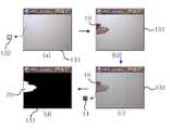
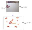
이와 달리 S5 과정의 판단 결과 촬상부(120)의 촬상 영상의 수신 후에도 셀별 이미지 데이터 값의 변화가 발생한 경우에는 가상스크린(131)에 포함된 셀 중 이미지 데이터 값이 변화된 셀을 추출하는 것에 의해 이미지 객체를 추출한다. 도 4는 도 3 내지 도 6 과정에의 의한 상술한 이미지 객체 추출과정을 도시한 것으로서, 도 4에 도시된 바와 같이, S3 과정의 경우에는 도 4의 (a)와 같이 초기 영상의 변화가 없다가, 사람의 손 등의 촬상 대상 영상 이미지(10)가 표시부 영역으로 진입하면 도 4(b)와 같이 가상스크린(131)에는 사람의 손 영상을 가지는 촬상 대상 영상이미지(10)가 출력된다. 이후, 영상객체반응부(130)는 도 4의 (c)와 같이 셀 별로 이미지 데이터 값의 변화를 검출하여 변화된 이미지 데이터 값을 셀들을 추출하는 것에 의해 촬영된 영상 이미지에 대한 이미지객체(20)를 추출한다(S6).On the other hand, if the change in the image data value for each cell occurs even after the
S6 과정에 의해 이미지객체(20)가 추출된 후에는 영상객체반응부(130)는 표시부(110)의 출력 영상을 기 지정된 방식으로 변환하여 출력한다. 여기서 기 지정된 방식이라 함은 특정되지 않은 다양한 방식의 영상출력 방식을 갖는다.After the
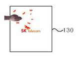
도 5 및 도 6은 이미지객체(20)에 대응한 표시부(100)를 통한 영상 출력 방식의 실시 예들을 나타낸다. 도 5의 경우에는 원래의 표시부(110)의 출력 영상 위에 새로운 영상 이미지들이 출력되도록 설정한 것을 나타내는 것으로서 새로운 나비 이미지 객체들이 출력되는 것을 나타낸다. 그리고 도 6의 경우에는 추출된 이미지객체(20)의 주변 영역에 새로운 이미지 객체들을 출력하는 것을 나타내는 것으로서 촬상된 손이 이미지 주변으로 나비 이미지 객체들을 출력하여 줌으로서 손에서 나비들이 나오거나 또는 나비들이 손으로 모여드는 것과 같이 표시부 화면을 출력하는 것을 나타낸다.5 and 6 illustrate embodiments of an image output method through the
이러한 출력 방식의 출력 영상의 제어는 자바 또는 자바애플릿 등의 프로그 램에 의해, 촬상 대상물의 영상 영역을 중심으로 화면의 영상을 갱신하거나, 촬상 대상물 주위로 영상 이미지 객체들이 집중되도록 하거나, 또는 출력 화면 영상이 촬상 대상물의 영상 영역을 중심으로 하는 물결무늬 형태로 변화되어 출력되도록 하는 등의 다양한 영상 출력 방식이 적용될 수 있다(S7).The control of the output image of the output method is performed by a program such as Java or Java applet to update the image of the screen around the image area of the image pickup object, or to concentrate the image image objects around the image pickup object, or to output the image. Various image output methods may be applied such that the image is converted into a wave pattern centering on the image area of the image to be output (S7).
S7과정에 의해 화면이 갱신된 이후 영상객체반응부(130)는 갱신된 화면을 이용하여 다시 셀별 변경 이미지 데이터 값을 갱신하여 저장한다(S8).After the screen is updated by the process S7, the image
이 후 촬상 영상 객체 대응 화면 출력 시스템의 구동이 종료되지 않는 경우에는 S4 과정으로 이동하여 처리과정을 반복 수행한다(S9).After that, if the driving of the screen output system corresponding to the captured image object does not end, the process moves to step S4 to repeat the process (S9).
상술한 바와 같은 본원 발명의 촬상 영상 객체 대응 화면 출력 시스템 및 그 방법은 표시부(110)를 시청하는 사람들과 표시부(110) 출력 영상이 서로 상호작용하도록 표시부(110)의 출력화면을 제어하여 출력할 수 있도록 한다.As described above, the system for outputting an image corresponding to the captured image object and a method thereof may control and output an output screen of the
도 7은 본원발명의 촬상 영상 객체 대응 화면 출력 시스템의 일 실시예를 나타내는 도면이다.FIG. 7 is a diagram illustrating an embodiment of a system for outputting a captured image object corresponding to the present invention. FIG.
도 7에 도시된 바와 같이 상술한 본원 발명의 촬상 영상 객체 대응 화면 출력 시스템은 촬상부(120)로서의 카메라(120')와, 영상객체반응부(130)를 소프트웨어 형태로 탑재하며 저장부(140)가 내장되는 PC(130')와, PC(130')의 출력 영상을 표시하는 표시부로서의 LCD(140')는 LCD외에 PDP 디스플레이장치, 또는 영상투사기와 스크린으로 구성되는 투영장치 등으로 다양하게 구현될 수 있으며, 이 경우 카메라(120')는 LCD, PDP 디스플레이장치, 또는 스크린의 화면 출력 영역만을 촬상하 도록 설정된다.As illustrated in FIG. 7, the above-described screen image output system for an image-capable object according to the present invention includes a
상술한 본원 발명은 사용자와 상호작용하는 화면 출력 시스템을 구현함에 있어서, 카메라에 비친 화상에 사람의 접근 등으로 변화가 생길 경우, 변화에 대한 소프트웨어 적인 추적을 해당 화상에 대한 RGB 컬러(color) 값 등의 이미지 데이터 값의 변화로만 간단하게 해결함으로써 선행 기술에 비해 일체의 추가 장비의 필요 없이 촬상 영상 객체 대응 화면 출력을 용이하게 구현할 수 있도록 하는 효과를 제공한다.In the above-described present invention, in implementing a screen output system that interacts with a user, when a change occurs due to a person's access to an image reflected on a camera, the software tracks the change to RGB color values of the corresponding image. By simply solving the change of the image data value, such as, it provides an effect that can easily implement the output image corresponding to the captured image object without the need of any additional equipment compared to the prior art.
또한, 상술한 본원 발명은 화면 변화의 결과를 컨텐츠(Contents) 개발 과정에서 사용하는 일반적인 객체의 형태로 반환 해주므로, 비교적 개발툴(tool)에 구애 받지않고 컨텐츠를 개발할 수 있도록 하며, 작동 원리가 간단하기 때문에 보정과 설정 과정이 간단하여 시스템의 구현을 더욱 용이하게 하는 효과를 제공한다.In addition, the present invention described above returns the result of the screen change in the form of a general object used in the content development process, so that the content can be developed relatively regardless of the development tool (tool), the operation principle is Because of its simplicity, the calibration and setup process is simple, making the system easier to implement.
또한, 상술한 본원 발명은 광고, 홍보 등에 사용되는 경우 광고 대상자와의 상호작용을 수행할 수 있도록 함으로써 광고효과를 극대화시키는 효과를 제공한다.In addition, the present invention described above provides an effect of maximizing the advertising effect by enabling interaction with the advertising target when used in advertising, promotion, and the like.
Claims (6)
Translated fromKoreanPriority Applications (1)
| Application Number | Priority Date | Filing Date | Title |
|---|---|---|---|
| KR1020060030537AKR20070099282A (en) | 2006-04-04 | 2006-04-04 | Captured video object-adaptive screen output system and method |
Applications Claiming Priority (1)
| Application Number | Priority Date | Filing Date | Title |
|---|---|---|---|
| KR1020060030537AKR20070099282A (en) | 2006-04-04 | 2006-04-04 | Captured video object-adaptive screen output system and method |
Publications (1)
| Publication Number | Publication Date |
|---|---|
| KR20070099282Atrue KR20070099282A (en) | 2007-10-09 |
Family
ID=38804758
Family Applications (1)
| Application Number | Title | Priority Date | Filing Date |
|---|---|---|---|
| KR1020060030537ACeasedKR20070099282A (en) | 2006-04-04 | 2006-04-04 | Captured video object-adaptive screen output system and method |
Country Status (1)
| Country | Link |
|---|---|
| KR (1) | KR20070099282A (en) |
Cited By (2)
| Publication number | Priority date | Publication date | Assignee | Title |
|---|---|---|---|---|
| WO2012087638A1 (en)* | 2010-12-22 | 2012-06-28 | Intel Corporation | Object mapping techniques for mobile augmented reality applications |
| KR20150108571A (en)* | 2014-03-18 | 2015-09-30 | 광운대학교 산학협력단 | An information display device of a mirror display for advertisement and shopping by recognizing the reflected images on the mirror and method thereof |
- 2006
- 2006-04-04KRKR1020060030537Apatent/KR20070099282A/ennot_activeCeased
Cited By (3)
| Publication number | Priority date | Publication date | Assignee | Title |
|---|---|---|---|---|
| WO2012087638A1 (en)* | 2010-12-22 | 2012-06-28 | Intel Corporation | Object mapping techniques for mobile augmented reality applications |
| US8913085B2 (en) | 2010-12-22 | 2014-12-16 | Intel Corporation | Object mapping techniques for mobile augmented reality applications |
| KR20150108571A (en)* | 2014-03-18 | 2015-09-30 | 광운대학교 산학협력단 | An information display device of a mirror display for advertisement and shopping by recognizing the reflected images on the mirror and method thereof |
Similar Documents
| Publication | Publication Date | Title |
|---|---|---|
| CN108615248B (en) | Method, device and equipment for relocating camera attitude tracking process and storage medium | |
| EP2531979B1 (en) | Depth camera compatibility | |
| US9017163B2 (en) | System and method for acquiring virtual and augmented reality scenes by a user | |
| US8619122B2 (en) | Depth camera compatibility | |
| KR101932537B1 (en) | Method and Apparatus for displaying the video on 3D map | |
| CN106355153A (en) | Virtual object display method, device and system based on augmented reality | |
| CN108416285A (en) | Rifle ball linkage surveillance method, apparatus and computer readable storage medium | |
| JP7657308B2 (en) | Method, apparatus and system for generating a three-dimensional model of a scene - Patents.com | |
| WO2001035208A1 (en) | Method for acquisition of motion capture data | |
| CN101931823A (en) | Method and device for displaying 3D images | |
| WO2010038693A1 (en) | Information processing device, information processing method, program, and information storage medium | |
| JP7403967B2 (en) | Information processing device, video generation device, image processing system, control method and program thereof | |
| US20020136455A1 (en) | System and method for robust foreground and background image data separation for location of objects in front of a controllable display within a camera view | |
| CN105850109A (en) | Information processing device, recording medium, and information processing method | |
| JP2009080514A (en) | Sensor arrangement design support system | |
| KR20010095900A (en) | 3D Motion Capture analysis system and its analysis method | |
| US20120201417A1 (en) | Apparatus and method for processing sensory effect of image data | |
| KR20070099282A (en) | Captured video object-adaptive screen output system and method | |
| JP6515022B2 (en) | Observation area estimation method, observation area estimation apparatus, and program | |
| KR101850134B1 (en) | Method and apparatus for generating 3d motion model | |
| KR20190112407A (en) | Operating method for Holoportation contents | |
| JP2003023562A (en) | Image photographic system and camera system | |
| JP5066047B2 (en) | Information processing apparatus, information processing method, program, and information storage medium | |
| KR101957417B1 (en) | Motion recognition control system and method for separately displaying shot image | |
| CN109117000B (en) | An interactive holographic blackboard system |
Legal Events
| Date | Code | Title | Description |
|---|---|---|---|
| A201 | Request for examination | ||
| PA0109 | Patent application | Patent event code:PA01091R01D Comment text:Patent Application Patent event date:20060404 | |
| PA0201 | Request for examination | ||
| E902 | Notification of reason for refusal | ||
| PE0902 | Notice of grounds for rejection | Comment text:Notification of reason for refusal Patent event date:20070430 Patent event code:PE09021S01D | |
| E601 | Decision to refuse application | ||
| PE0601 | Decision on rejection of patent | Patent event date:20070917 Comment text:Decision to Refuse Application Patent event code:PE06012S01D Patent event date:20070430 Comment text:Notification of reason for refusal Patent event code:PE06011S01I | |
| PG1501 | Laying open of application |