KR20070097412A - Binder-Included Implants and Implantation Methods Between Spines - Google Patents
Binder-Included Implants and Implantation Methods Between SpinesDownload PDFInfo
- Publication number
- KR20070097412A KR20070097412AKR1020077009238AKR20077009238AKR20070097412AKR 20070097412 AKR20070097412 AKR 20070097412AKR 1020077009238 AKR1020077009238 AKR 1020077009238AKR 20077009238 AKR20077009238 AKR 20077009238AKR 20070097412 AKR20070097412 AKR 20070097412A
- Authority
- KR
- South Korea
- Prior art keywords
- binder
- brace
- implant
- wing
- capture device
- Prior art date
- Legal status (The legal status is an assumption and is not a legal conclusion. Google has not performed a legal analysis and makes no representation as to the accuracy of the status listed.)
- Withdrawn
Links
- 238000000034methodMethods0.000titleclaimsabstractdescription222
- 239000007943implantSubstances0.000titleclaimsabstractdescription193
- 238000002513implantationMethods0.000titleabstractdescription14
- 239000011230binding agentSubstances0.000claimsabstractdescription244
- 230000008569processEffects0.000claimsabstractdescription143
- 125000006850spacer groupChemical group0.000claimsabstractdescription80
- 230000033001locomotionEffects0.000claimsabstractdescription37
- 239000000463materialSubstances0.000claimsdescription28
- 208000002193PainDiseases0.000claimsdescription11
- 230000008878couplingEffects0.000claimsdescription9
- 238000010168coupling processMethods0.000claimsdescription9
- 238000005859coupling reactionMethods0.000claimsdescription9
- 229920000728polyesterPolymers0.000claimsdescription6
- 239000003356suture materialSubstances0.000claimsdescription6
- 230000000670limiting effectEffects0.000claimsdescription5
- 229920004934Dacron®Polymers0.000claimsdescription4
- 239000005020polyethylene terephthalateSubstances0.000claimsdescription4
- 239000010935stainless steelSubstances0.000claimsdescription4
- 229910001220stainless steelInorganic materials0.000claimsdescription4
- 238000003825pressingMethods0.000claimsdescription3
- 210000003041ligamentAnatomy0.000abstractdescription23
- 238000005192partitionMethods0.000abstractdescription20
- 238000005452bendingMethods0.000abstractdescription16
- 230000002829reductive effectEffects0.000abstractdescription3
- 238000002054transplantationMethods0.000abstractdescription2
- 239000004696Poly ether ether ketoneSubstances0.000description17
- 229920002530polyetherether ketonePolymers0.000description17
- 238000003780insertionMethods0.000description14
- 230000037431insertionEffects0.000description14
- 230000007246mechanismEffects0.000description13
- 210000001519tissueAnatomy0.000description13
- 229920000642polymerPolymers0.000description11
- 210000000988bone and boneAnatomy0.000description9
- 230000003412degenerative effectEffects0.000description9
- 210000003128headAnatomy0.000description8
- 208000037265diseases, disorders, signs and symptomsDiseases0.000description7
- 230000006870functionEffects0.000description7
- 230000008901benefitEffects0.000description6
- 230000004927fusionEffects0.000description6
- 230000006378damageEffects0.000description5
- 230000007423decreaseEffects0.000description5
- 208000035475disorderDiseases0.000description5
- 229920001652poly(etherketoneketone)Polymers0.000description5
- 229920000249biocompatible polymerPolymers0.000description4
- 229920001577copolymerPolymers0.000description4
- 238000010586diagramMethods0.000description4
- 238000003384imaging methodMethods0.000description4
- 210000004705lumbosacral regionAnatomy0.000description4
- 239000000203mixtureSubstances0.000description4
- 230000036961partial effectEffects0.000description4
- 208000005198spinal stenosisDiseases0.000description4
- 238000001356surgical procedureMethods0.000description4
- OKTJSMMVPCPJKN-UHFFFAOYSA-NCarbonChemical compound[C]OKTJSMMVPCPJKN-UHFFFAOYSA-N0.000description3
- 238000013459approachMethods0.000description3
- 229910052799carbonInorganic materials0.000description3
- 239000011521glassSubstances0.000description3
- 208000014674injuryDiseases0.000description3
- 239000000155meltSubstances0.000description3
- 210000005036nerveAnatomy0.000description3
- 229920002959polymer blendPolymers0.000description3
- 229920001169thermoplasticPolymers0.000description3
- 239000004416thermosoftening plasticSubstances0.000description3
- 230000008733traumaEffects0.000description3
- 208000031264Nerve root compressionDiseases0.000description2
- PXHVJJICTQNCMI-UHFFFAOYSA-NNickelChemical compound[Ni]PXHVJJICTQNCMI-UHFFFAOYSA-N0.000description2
- 208000031481Pathologic ConstrictionDiseases0.000description2
- 206010037779RadiculopathyDiseases0.000description2
- 206010041591Spinal osteoarthritisDiseases0.000description2
- 229910000831SteelInorganic materials0.000description2
- RTAQQCXQSZGOHL-UHFFFAOYSA-NTitaniumChemical compound[Ti]RTAQQCXQSZGOHL-UHFFFAOYSA-N0.000description2
- 229920004695VICTREX™ PEEKPolymers0.000description2
- 230000002411adverseEffects0.000description2
- 239000000560biocompatible materialSubstances0.000description2
- 230000008468bone growthEffects0.000description2
- 239000002131composite materialSubstances0.000description2
- 201000010099diseaseDiseases0.000description2
- 239000000945fillerSubstances0.000description2
- 238000002844meltingMethods0.000description2
- 230000008018meltingEffects0.000description2
- 229910052751metalInorganic materials0.000description2
- 239000002184metalSubstances0.000description2
- 238000012986modificationMethods0.000description2
- 230000004048modificationEffects0.000description2
- 239000002861polymer materialSubstances0.000description2
- 230000009257reactivityEffects0.000description2
- 239000010959steelSubstances0.000description2
- 230000036262stenosisEffects0.000description2
- 208000037804stenosisDiseases0.000description2
- 229910000811surgical stainless steelInorganic materials0.000description2
- 208000024891symptomDiseases0.000description2
- 210000000115thoracic cavityAnatomy0.000description2
- 239000010936titaniumSubstances0.000description2
- 229910052719titaniumInorganic materials0.000description2
- 208000006820ArthralgiaDiseases0.000description1
- 208000031638Body WeightDiseases0.000description1
- 229920000049Carbon (fiber)Polymers0.000description1
- 208000000094Chronic PainDiseases0.000description1
- 229910000531Co alloyInorganic materials0.000description1
- 229910000684Cobalt-chromeInorganic materials0.000description1
- 208000003618Intervertebral Disc DisplacementDiseases0.000description1
- 208000000112MyalgiaDiseases0.000description1
- 206010028570MyelopathyDiseases0.000description1
- 208000028389Nerve injuryDiseases0.000description1
- 206010033372Pain and discomfortDiseases0.000description1
- 241000486437PanolisSpecies0.000description1
- 229920008285Poly(ether ketone) PEKPolymers0.000description1
- 238000010521absorption reactionMethods0.000description1
- 230000032683agingEffects0.000description1
- 239000000956alloySubstances0.000description1
- 210000003484anatomyAnatomy0.000description1
- 230000004888barrier functionEffects0.000description1
- 230000005540biological transmissionEffects0.000description1
- 230000015572biosynthetic processEffects0.000description1
- 210000004204blood vesselAnatomy0.000description1
- 230000037396body weightEffects0.000description1
- 239000004917carbon fiberSubstances0.000description1
- 210000003793centrosomeAnatomy0.000description1
- 230000008859changeEffects0.000description1
- 210000000038chestAnatomy0.000description1
- 239000010952cobalt-chromeSubstances0.000description1
- 238000000748compression mouldingMethods0.000description1
- 230000008602contractionEffects0.000description1
- 230000007850degenerationEffects0.000description1
- 238000013461designMethods0.000description1
- 238000011161developmentMethods0.000description1
- 230000018109developmental processEffects0.000description1
- 210000000613ear canalAnatomy0.000description1
- 238000005516engineering processMethods0.000description1
- 230000005713exacerbationEffects0.000description1
- 238000001125extrusionMethods0.000description1
- 239000000835fiberSubstances0.000description1
- 239000003193general anesthetic agentSubstances0.000description1
- 229940005494general anestheticsDrugs0.000description1
- 239000008240homogeneous mixtureSubstances0.000description1
- 238000001746injection mouldingMethods0.000description1
- 230000002452interceptive effectEffects0.000description1
- 230000009545invasionEffects0.000description1
- 230000003447ipsilateral effectEffects0.000description1
- 150000002576ketonesChemical class0.000description1
- 238000003754machiningMethods0.000description1
- 230000013011matingEffects0.000description1
- 238000005259measurementMethods0.000description1
- 238000010309melting processMethods0.000description1
- VNWKTOKETHGBQD-UHFFFAOYSA-NmethaneChemical compoundCVNWKTOKETHGBQD-UHFFFAOYSA-N0.000description1
- 239000000178monomerSubstances0.000description1
- 208000013465muscle painDiseases0.000description1
- 230000008764nerve damageEffects0.000description1
- 229910052759nickelInorganic materials0.000description1
- HLXZNVUGXRDIFK-UHFFFAOYSA-Nnickel titaniumChemical compound[Ti].[Ti].[Ti].[Ti].[Ti].[Ti].[Ti].[Ti].[Ti].[Ti].[Ti].[Ni].[Ni].[Ni].[Ni].[Ni].[Ni].[Ni].[Ni].[Ni].[Ni].[Ni].[Ni].[Ni].[Ni]HLXZNVUGXRDIFK-UHFFFAOYSA-N0.000description1
- 229910001000nickel titaniumInorganic materials0.000description1
- 230000003287optical effectEffects0.000description1
- 230000003647oxidationEffects0.000description1
- 238000007254oxidation reactionMethods0.000description1
- 230000000149penetrating effectEffects0.000description1
- 239000013500performance materialSubstances0.000description1
- 230000035479physiological effects, processes and functionsEffects0.000description1
- 229920006260polyaryletherketonePolymers0.000description1
- 229920001692polycarbonate urethanePolymers0.000description1
- 239000002952polymeric resinSubstances0.000description1
- 238000002360preparation methodMethods0.000description1
- 230000005855radiationEffects0.000description1
- 230000009467reductionEffects0.000description1
- 230000001105regulatory effectEffects0.000description1
- 239000011347resinSubstances0.000description1
- 229920005989resinPolymers0.000description1
- 239000007787solidSubstances0.000description1
- 210000001032spinal nerveAnatomy0.000description1
- 208000001413spine osteoarthritisDiseases0.000description1
- 208000005801spondylosisDiseases0.000description1
- 230000006641stabilisationEffects0.000description1
- 238000011105stabilizationMethods0.000description1
- 230000035882stressEffects0.000description1
- 239000000758substrateSubstances0.000description1
- 230000000153supplemental effectEffects0.000description1
- 238000003786synthesis reactionMethods0.000description1
- 229920003002synthetic resinPolymers0.000description1
- 230000001225therapeutic effectEffects0.000description1
- 239000012815thermoplastic materialSubstances0.000description1
- 230000000007visual effectEffects0.000description1
- XLYOFNOQVPJJNP-UHFFFAOYSA-NwaterSubstancesOXLYOFNOQVPJJNP-UHFFFAOYSA-N0.000description1
- 210000002517zygapophyseal jointAnatomy0.000description1
Images


Classifications
- A—HUMAN NECESSITIES
- A61—MEDICAL OR VETERINARY SCIENCE; HYGIENE
- A61F—FILTERS IMPLANTABLE INTO BLOOD VESSELS; PROSTHESES; DEVICES PROVIDING PATENCY TO, OR PREVENTING COLLAPSING OF, TUBULAR STRUCTURES OF THE BODY, e.g. STENTS; ORTHOPAEDIC, NURSING OR CONTRACEPTIVE DEVICES; FOMENTATION; TREATMENT OR PROTECTION OF EYES OR EARS; BANDAGES, DRESSINGS OR ABSORBENT PADS; FIRST-AID KITS
- A61F2/00—Filters implantable into blood vessels; Prostheses, i.e. artificial substitutes or replacements for parts of the body; Appliances for connecting them with the body; Devices providing patency to, or preventing collapsing of, tubular structures of the body, e.g. stents
- A61F2/02—Prostheses implantable into the body
- A61F2/30—Joints
- A61F2/44—Joints for the spine, e.g. vertebrae, spinal discs
- A—HUMAN NECESSITIES
- A61—MEDICAL OR VETERINARY SCIENCE; HYGIENE
- A61B—DIAGNOSIS; SURGERY; IDENTIFICATION
- A61B17/00—Surgical instruments, devices or methods
- A61B17/56—Surgical instruments or methods for treatment of bones or joints; Devices specially adapted therefor
- A61B17/58—Surgical instruments or methods for treatment of bones or joints; Devices specially adapted therefor for osteosynthesis, e.g. bone plates, screws or setting implements
- A61B17/68—Internal fixation devices, including fasteners and spinal fixators, even if a part thereof projects from the skin
- A61B17/70—Spinal positioners or stabilisers, e.g. stabilisers comprising fluid filler in an implant
- A61B17/7062—Devices acting on, attached to, or simulating the effect of, vertebral processes, vertebral facets or ribs ; Tools for such devices
- A61B17/7068—Devices comprising separate rigid parts, assembled in situ, to bear on each side of spinous processes; Tools therefor
Landscapes
- Health & Medical Sciences (AREA)
- Orthopedic Medicine & Surgery (AREA)
- Neurology (AREA)
- Life Sciences & Earth Sciences (AREA)
- Surgery (AREA)
- Engineering & Computer Science (AREA)
- Biomedical Technology (AREA)
- General Health & Medical Sciences (AREA)
- Veterinary Medicine (AREA)
- Heart & Thoracic Surgery (AREA)
- Public Health (AREA)
- Animal Behavior & Ethology (AREA)
- Molecular Biology (AREA)
- Medical Informatics (AREA)
- Nuclear Medicine, Radiotherapy & Molecular Imaging (AREA)
- Cardiology (AREA)
- Oral & Maxillofacial Surgery (AREA)
- Transplantation (AREA)
- Vascular Medicine (AREA)
- Prostheses (AREA)
- Surgical Instruments (AREA)
- Materials For Medical Uses (AREA)
Abstract
Translated fromKoreanDescription
Translated fromKorean[우선권 주장][Priority claim]
본 출원은 다음과 같은 동시 계류 중인 출원들의 우선권을 주장하는 출원으로서 그 전체를 본 출원에 포함한다.This application is the application claiming the priority of the following concurrent pending applications, the entirety of which is included in the present application.
주커만(Zucherman) 등에 의한 발명의 명칭이 "가시돌기들 사이의 바인더 포함 임플란트 및 이식 방법(Interspinous Process Implant Including a Binder and Method of Implanation)"인 2004년 9월 23일 출원된 미국 가출원 제60/612,465호(변리사 서류 번호 KLYC-01109US0);US Provisional Application No. 60 / 612,465, filed Sep. 23, 2004, entitled "Interspinous Process Implant Including a Binder and Method of Implanation," by Zucherman et al., Entitled "Interspinous Process Implant Including a Binder and Method of Implanation." No. (Patent Attorney No. KLYC-01109US0);
주커만(Zucherman) 등에 의한 발명의 명칭이 "가시돌기들 사이의 바인더 포함 임플란트 및 이식 방법(Interspinous Process Implant Including a Binder and Method of Implanation)"인 2005년 3월 31일 출원된 미국 출원 제11/095,680(변리사 서류 번호 KLYC-01109US1); 및United States Application No. 11 / 095,680, filed Mar. 31, 2005, entitled "Interspinous Process Implant Including a Binder and Method of Implanation" by Zucherman et al. (Patent Attorney No. KLYC-01109US1); And
주커만(Zucherman) 등에 의한 발명의 명칭이 "가시돌기들 사이의 바인더 포함 임플란트 및 이식 방법(Interspinous Process Implant Including a Binder and Method of Implanation)"인 2005년 3월 31일 출원된 미국 출원 제11/095,440호(변리사 서류 번호 KLYC-01109US2).United States Application No. 11 / 095,440, filed March 31, 2005, entitled "Interspinous Process Implant Including a Binder and Method of Implanation," by Zucherman et al. Korean Patent Attorney No. KLYC-01109US2.
본 발명은 가시돌기 사이의 임플란트 에 관한 것이다.The present invention relates to implants between spinous processes.
노령화 사회로 접어듦에 따라, 노인들의 특징인 유해 척추 질환(adverse spinal conditions)이 증가할 것으로 예상된다. 노령화됨에 따라 특정한 생화학적 변화가 발생될 수 있으며, 생화학적 변화는 몸 전체에서 관찰된 조직에 영향을 미친다. 척추에 있어서는, 추간판(intervertebral disks)의 조직이 손상될 수 있고, 부분적으로는 추간판의 섬유테(annulus fibrosus)의 조직이 퇴행적 효과(degenerative effects)에 기인하여 약해질 수 있다. 척추굳음증(spondylosis) 또는 척추골관절염(spinal osteoarthritis)은 정상적인 척추의 조직 및 기능을 상실하게 하는 퇴행성 장애의 일 예이다. 퇴행성 과정은 척추의 자궁경부(cervical) 영역, 가슴(thoracic) 영역 및/또는 허리(lumbar) 영역에 영향을 미칠 수 있고, 추간판과 척추후관절(facet joints)에 영향을 미친다. 퇴행성 장애와 연관된 통증은 전방 굽힘(flexion) 및 젖힘(hyperextension) 중 어느 하나 또는 둘 다에 의하여 시작된다. 척추의 가슴 영역에서의 척추굳음증은 굽히는 동안의 디스크(disk) 통증과 젖히는 동안의 후관절 통증을 야기한다. 척추굳음증은 사람 몸무게의 대부분을 지탱하는 척추의 허리 영역에 영향을 미칠 수 있으며, 움직임은 섬유테와 후관절에 있는 통증 섬유를 자극할 수 있다.As we move into an aging society, adverse spinal conditions, which are characteristic of older people, are expected to increase. As we age, certain biochemical changes can occur, which affect tissues observed throughout the body. In the spine, the tissue of the intervertebral disks may be damaged, and in part the tissue of the annulus fibrosus of the intervertebral disc may weaken due to degenerative effects. Spondylosis or spinal osteoarthritis is an example of a degenerative disorder that causes tissue and function of the normal spine to lose. Degenerative processes can affect the cervical, thoracic and / or lumbar regions of the spine and affect the intervertebral discs and facet joints. Pain associated with degenerative disorders is initiated by either or both of anterior flexion and hyperextension. Spinal firmness in the thoracic region of the spine causes disk pain during bending and back joint pain during tilting. Spinal firmness can affect the lumbar region of the spine, which supports most of the body's weight, and movement can stimulate pain fibers in the fibrous rim and posterior joints.
시간이 지남에 따라, 디스크 높이의 손실은, 세그먼트 불안정(segment instability)의 결과를 낳으며 궁극적으로는 척추 협착증(중심관 협착증(central canal stenosis) 및 측면 협착증(lateral stenosis)을 포함하나 이에 한정되지 않 음)의 결과를 낳는 이른바 운동 부분(motion segment)의 모든 구성이 쇠약해지는 퇴행성 연속단계의 결과를 발생시킨다. 척추 협착증(spinal stenosis)은 신경뿌리를 압박하고 근통을 야기하는 추간공 영역(foraminal area, 신경과 혈관의 통로를 위한 유효한 공간)의 축소 결과를 낳는다. 척추 협착증의 다른 징후는 척수병증(myelopathy)이다. 신장(extension)과 동측 회전은 추공간 영역을 더욱 감소시키며, 통증, 신경뿌리 압착 및 신경손상을 야기한다. 쇠약해지는 동안, 디스크는 추간판 타출증(herniated)이 되거나, 내부적인 아픔 및 만성적인 통증이 될 수 있다. 증상이 앞(디스크)과 뒤(면(facet) 및 구멍(foramen)) 구조들의 양자로부터 발생된 것일 때, 환자는 굽힘과 신장의 위치를 견딜 수 없다.Over time, loss of disc height results in segment instability and ultimately includes but is not limited to spinal stenosis (central canal stenosis and lateral stenosis). All the components of the so-called motion segment resulting in um) result in degenerate successive stages. Spinal stenosis results in a reduction in the foraminal area (an effective space for passage of nerves and blood vessels) that compresses the nerve roots and causes muscle pain. Another sign of spinal stenosis is myelopathy. Extension and ipsilateral rotation further reduces the spinal space region, causing pain, nerve root compression and nerve damage. While debilitating, the disc may become herniated, internal pain and chronic pain. When the symptom is from both the front (disc) and rear (facet and foramen) structures, the patient cannot tolerate the location of bending and extension.
퇴행성 척추 디스크 병과 관련된 고통을 처리하는 일반적인 시술(procedure)은 2개 이상의 인접한 척추체를 함께 용융시키는 장치를 사용하는 것이다. 상기 시술은 여러 가지의 용어로 알려져 있는데, 그 중 하나는 인터바디 퓨젼(interbody fusion)이다. 인터바디 퓨젼은 종래에 알려진 방법들과 장치들의 사용을 통하여 실행될 수 있다. 인터바디 퓨전은 스크류 장치(screw arrangement), 솔리드 본 임플란트 방법론(solid bone implant methodologies), 및 뼈 및/또는 물질을 포함하는 골성장(bone growth)으로 꾸려져 있는 메카니즘 또는 케이지(cage)을 포함하는 용융장치를 포함한다. 이들의 대부분은 척추체를 함께 용융하고, 연관된 통증을 경감시키기 위하여 인접한 척추체들 사이에 순차적으로 임플란트된다.A common procedure for dealing with pain associated with degenerative spinal disc disease is to use a device that melts two or more adjacent vertebral bodies together. The procedure is known in several terms, one of which is interbody fusion. Interbody fusion can be implemented through the use of methods and devices known in the art. Interbody fusion includes mechanisms or cages packed with screw arrangements, solid bone implant methodologies, and bone growth comprising bone and / or materials. A melting apparatus. Most of them melt together the vertebral bodies and are sequentially implanted between adjacent vertebral bodies to relieve associated pain.
이탈(slip)의 정도와 다른 요인(factor)에 따라, 의사는 척추뼈를 용융시키거나 척추뼈를 용융시키고 또한 보충 장치를 사용한다. 보충 장치들은 주용융장치 및 방법들과 관련되고, 용융공정을 돕는다. 보충 장치는 인접한 척추체으로부터의 뼈가 함께 성장할 때 몇 개월의 기간 동안 주용융장치를 통하여 인접한 척추체를 용융하기 위하여 돕는다. 이 기간 동안 충분한 뼈성장이 이루어질 수 있도록 하기 위하여 척추체는 서로에 대하여 움직이지 않도록 유지되는 것이 유리하다. 보충 장치는 후크 및 막대 장치들, 스크류 장치들, 그리고 스트랩(straps), 와이어(wires), 및 밴드(bands)를 포함하는 다른 장치들을 포함할 수 있으며, 상기 장치들은 모두 다른 하나에 대하여 상대적으로 척추의 한 영역이 움직이지 않도록 하는데 사용된다. 보충 장치는 일반적으로 광범위한 외과적 시술을 요구할 뿐만 아니라 주용융임플란트(primary fusion implant) 주변의 광범위한 시술이 요구되는 단점이 있다. 이러한 광범위한 외과적 시술은 이식(implantation) 동안 척추 신경에 피해를 야기하는 위험을 포함하는 추가적인 위험을 포함한다. 척추 용융(spinal fusion)은 일반적인 마취제의 사용을 요구하는 고침습성 수술(highly invasive surgery)을 포함하고, 그 자체가 추가적인 위험을 포함한다. 위험들은 전염의 가능성을 더 포함하고, 광범위한 외상, 및 주용융장치 또는 보충장치의 고정에 의하여 야기되는 척추뼈의 피해를 포함한다. 마지막으로, 척추 용융은 척추체들 사이의 상대적인 운동의 절대손실의 결과를 낳을 수 있다.Depending on the degree of slip and other factors, the surgeon melts or melts the vertebrae and also uses supplemental devices. Supplementary devices relate to the main melting device and methods and assist the melting process. The replenishment device helps melt the adjacent vertebral body through the main melter for a period of several months when bones from the adjacent vertebral bodies grow together. It is advantageous for the vertebral bodies to remain stationary relative to one another in order to allow sufficient bone growth to occur during this period. The replenishment device may include hook and rod devices, screw devices and other devices including straps, wires, and bands, all of which are relatively relative to one another. Used to keep one area of the spine from moving. The replenishment device generally requires a wide range of surgical procedures as well as a disadvantage of requiring a wide range of procedures around the primary fusion implant. Such extensive surgical procedures include additional risks, including the risk of causing damage to the spinal nerves during implantation. Spinal fusion includes highly invasive surgery, which requires the use of general anesthetics, and in itself involves additional risks. The risks further include the possibility of transmission and include extensive trauma and damage to the vertebrae caused by fixation of the main melt or replenishment device. Finally, spinal fusion can result in absolute loss of relative motion between vertebral bodies.
미국 특허 제5,496,318호(Howland)는 주용융장치를 임플란트하기 위하여 외과적 시술과 함께 사용하기 위한 척추의 안정화를 위한 보충 장치를 개시하고 있다. 미국 특허 제5,496,318호(Howland)는 벨트, 스틸케이블(steel cabel), 폴리테트라플루오로에탄 웹 재료(polytetrafluoroethane web material)에 의하여 두개의 조각이 함께 지지된 H 형상의 스페이서(spacer)를 개시하고 있다. H 형상의 스페이서(spacer)의 두 개의 조각 중 하나 또는 두 개의 단부는 각각의 단부와 확고하게 결합된 결합장치를 포함한다. 미국 특허 제5,496,318호(Howland)는 척추뼈가 바람직한 위치에 고정장치를 위치시키기 위한 사각형의 노치(notch)를 포함하도록 바람직하게 외과적으로 수정되어 있다고 개시하고 있다. 미국 특허 제5,496,318호(Howland)의 추가적인 단점으로는, 벨트, 케이블 및 웹재료가 이식 전에 그 크기가 측정되어야 하는 것과, 측정 시간을 포함함에 따른 시술 시간이 증가되는 것과, 결합장치들을 포함하는 (증가되는 크기를 갖는) 벨트, 케이블 및 웹재료(web material)의 양단에서 맞춤의 정확성이 저하되는 것 등이 있다.US Pat. No. 5,496,318 to Howland discloses a supplementary device for stabilization of the spine for use with surgical procedures to implant the main melt device. US Pat. No. 5,496,318 (Howland) discloses an H-shaped spacer in which two pieces are supported together by a belt, steel cabel, and polytetrafluoroethane web material. . One or two ends of the two pieces of H-shaped spacers comprise coupling devices that are firmly engaged with each end. US Pat. No. 5,496,318 (Howland) discloses that the vertebrae are preferably surgically modified to include a rectangular notch for positioning the anchor in the desired position. A further disadvantage of US Pat. No. 5,496,318 (Howland) is that the belt, cable and web material must be measured in size before implantation, the procedure time increases as the measurement time is included, and the coupling devices (including coupling devices) Accuracy of fit at both ends of the belt, cable and web material (of increasing size), and the like.
미국 특허 제5,609,634호(Voydeville)는 인접한 가시돌기들(spinous processes)과 동일한 물질로 만들어진 인대(ligament) 사이에 위치하는 반가요성 극돌 간 블럭(semi-flexible interspinous block)을 포함하는 보철(prosthesis)을 개시하고 있다. 의사는 극돌간 블럭과 주위의 가시돌기들을 통하여 인대를 숫자 '8'의 형상 또는 극돌간 블럭과 주위의 가시돌기들을 통하여 타원형으로 매고, 극돌간 블럭을 그 자리에 고정하기 위하여 그 자신에 인대를 봉합한다. 미국 특허 제5,609,634호(Voydeville)는 가시돌기들과 관련된 조직의 제거 또는/및 이탈이 요구되며, 잠재적으로 중요한 외상 또는 피해의 결과를 낳는 단점이 있다. 미국 특허 제5,609,634호(Voydeville)는 의사가 극돌간 블럭을 통하여 극돌간 인대(interspinous ligament)를 매어야 하는 단점이 더 있다. 이러한 시술은, 의사가 관심 영역을 내다 보는 것은 그 관심 영역이 피로 뒤덮힘으로써 까다로워지기 때문 에, 많은 주의와 시간이 요구된다.U.S. Patent No. 5,609,634 (Voydeville) discloses a prosthesis comprising a semi-flexible interspinous block located between adjacent spinous processes and ligaments made of the same material. It is starting. The surgeon ties the ligament through the interlude block and the surrounding spines to form the number '8' or elliptical through the spinous block and the surrounding spines and attaches the ligament to itself to fix the interlude block in place. Suture. U.S. Patent 5,609,634 (Voydeville) requires the removal or removal of tissue associated with spinous processes and has the disadvantage of causing potentially significant trauma or damage. U.S. Patent No. 5,609,634 (Voydeville) further has the disadvantage that a physician must tie an interspinous ligament through an interlude block. This procedure requires a lot of attention and time because the doctor's looking at the area of interest is complicated by the fatigue of the area of interest.
인접한 척추체의 접힘과 신장을 제한하기 위한 장치 및 시술이 간단하고 수행하기 쉽다면, 모든 뼈와 인대 그리고 척추를 둘러싸고 포함하는 다른 조직을 손대지 않은 상태로 남겨두는 것이 바람직하나 필수적인 것은 아니다. 따라서, 최소한으로 침습적이고, 주용융장치 및 방법 또는 다른 척추고정장치 및 방법을 대체할 수 있는 시술 및 임플란트가 필요하다. 이에 따라, 척추관협착층, 척추의 퇴화 및 피해에 의하여 야기되는 다른 질병들에 의하여 발생하는 고통을 경감시키는 척추 임플란트의 개발이 필요하다. 이러한 임플란트는 추간공(foraminal) 영역을 증가시키고 척추의 혈관과 신경에 가하진 압력을 줄이기 위하여 척추뼈 사이의 공간을 유지하거나 증가시키고, 척추굳음증과 다른 퇴화적 상태에 의하여 발생되는 고통을 감속시키기 위하여 척추굽힘을 제한 또는 방지한다.If the devices and procedures for limiting the folding and stretching of adjacent vertebral bodies are simple and easy to perform, it is desirable but not essential to leave all bones, ligaments and other tissues surrounding the vertebrae intact. Thus, there is a need for procedures and implants that are minimally invasive and can replace main melt devices and methods or other spinal fixation devices and methods. Accordingly, there is a need for the development of spinal implants that alleviate the pain caused by spinal canal constriction layers, other diseases caused by spinal degeneration and damage. These implants maintain or increase the space between the vertebrae to increase the area of the foraminal, reduce the pressure on the vessels and nerves of the spine, and slow the pain caused by stiffness and other degenerative conditions. Limit or prevent spinal bending.
척추의 생리학을 보전하며 척추 임플란트를 위한 최소한의 침습적 및 외과적인 이식 방법의 개발이 요구된다. 척추의 뚜렷한 해부학적 구조에 순응하며, 척추의 외상을 최소화하고, 외과적 이식의 침습적인 방법에 대한 필요성을 제거하는 임플란트가 여전히 요구된다. 이에 따라, 척추의 굽힘과 접힘에 의하여 악화되는 유해 척추 질환(adverse spinal condition)에 대한 준비가 요구된다.There is a need to preserve the physiology of the spine and to develop minimally invasive and surgical implantation methods for spinal implants. There is still a need for implants that conform to the distinct anatomical structure of the spine, minimize the trauma of the spine, and eliminate the need for invasive methods of surgical implantation. Accordingly, there is a need for preparation for an adverse spinal condition that is exacerbated by bending and folding of the spine.
첨부된 도면을 참조하여 본 발명의 실시예에 대하여 더욱 구체적으로 설명한다.With reference to the accompanying drawings will be described in detail an embodiment of the present invention.
도 1은 척추를 펴는 동안 인접한 가시돌기(adjacent spinous process)의 상대적인 움직임을 제한하거나 방해할 수 있는 극돌간 임플란트(interspinous implant)의 사시도이다.1 is a perspective view of an interspinous implant that may limit or impede the relative movement of adjacent adjacent spinous processes during spine extension.
도 2a는 인접한 가시돌기 사이에 위치하는 도 1의 임플란트의 배면도이다.FIG. 2A is a rear view of the implant of FIG. 1 positioned between adjacent spinous processes. FIG.
도 2b는 인접한 가시돌기 사이에 위치하는 도 1 및 도 2a의 극돌간 임플란트의 스페이서(spacer)의 일측 단면도이다.FIG. 2B is a cross-sectional side view of the spacer of the interlucent implant of FIGS. 1 and 2A positioned between adjacent spinous processes.
도 2c는 척추가 굽혀지는 동안 도 2b의 스페이서의 단면도이다.FIG. 2C is a cross-sectional view of the spacer of FIG. 2B while the spine is bent.
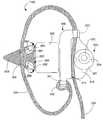
도 3a는 캡쳐장치(capture device)의 옆에 고정 및 지지시키기 위한 신연 가이드(distraction guide), 스페이서, 브레이스(brace) 및 바인더(binder)를 갖는 본 발명에 따르는 임플란트의 일실시예를 나타내는 사시도이다.FIG. 3A is a perspective view of one embodiment of an implant according to the present invention having a distraction guide, spacer, brace and binder for securing and supporting the side of a capture device; FIG. .
도 3b는 캡쳐장치의 로브(lob)를 수용하기 위한 홈(recess)을 갖는 브레이스 격벽을 포함하는 본 발명에 따르는 임플란트의 양자택일적인 실시예의 측면도이다.3B is a side view of an alternative embodiment of an implant according to the present invention that includes a brace bulkhead having a recess for receiving a lob of the capture device.
도 3c는 브레이스 격벽에 대하여 바인더를 고정하기 위한 스프링이 장착된 캠을 갖는 캡쳐장치를 포함하는 본 발명에 따르는 임플란트의 다른 실시예의 측면도이다.3C is a side view of another embodiment of an implant according to the present invention including a capture device having a spring-loaded cam for securing a binder against a brace bulkhead.
도 3d는 위치에 바인더를 고정하기 위한 두개의 스프링이 장착된 캠을 갖는 캡쳐장치를 포함하는 본 발명에 따르는 임플란트의 또 다른 실시예의 측면도이다.3D is a side view of another embodiment of an implant according to the present invention comprising a capture device having two spring-loaded cams for securing a binder in position.
도 4a는 인접한 가시돌기 사이에 위치하는 도 3a의 임플란트의 단부도이다.4A is an end view of the implant of FIG. 3A positioned between adjacent spinous processes.
도 4b는 인접한 가시돌기 사이에 위치하는 도 3a의 임플란트의 단부도이다.4B is an end view of the implant of FIG. 3A positioned between adjacent spinous processes.
도 4c는 가시돌기가 바인더를 수용하기 위하여 외과적으로 수정되어 있는 경 우에, 인접한 가시돌기 사이에 위치하는 도 3a의 임플란트의 단부도이다.4C is an end view of the implant of FIG. 3A positioned between adjacent spinous processes, when the spinous processes are surgically modified to receive the binder.
도 5는 바인더의 길이에 따라 형상이 다양하게 변화된 바인더를 갖는 본 발명에 따르는 인접한 가시돌기 사이에 위치하는 도 3a의 임플란트의 단부도이다.FIG. 5 is an end view of the implant of FIG. 3A positioned between adjacent spinous processes in accordance with the present invention having a binder that varies in shape with the length of the binder.
도 6a는 인접한 가시돌기 사이에 위치하는 도 5의 임플란트의 단부도이다.6A is an end view of the implant of FIG. 5 positioned between adjacent spinous processes.
도 6b는 도 6a의 임플란트의 반대측 단부도이다.6B is an opposite end view of the implant of FIG. 6A.
도 6c는 바인더를 위한 끈(cord)을 갖는 본 발명에 따르는 임플란트의 다른 실시예의 단부도이다.6c is an end view of another embodiment of an implant according to the invention with a cord for a binder.
도 7a는 임플란트의 움직임을 더 제한하거나 방지하기 위하여 신연 가이드와 결합된 날개를 포함하는 본 발명에 따르는 임플란트의 실시예의 측면도이다.7A is a side view of an embodiment of an implant according to the present invention that includes wings coupled with distraction guides to further limit or prevent movement of the implant.
도 7b는 수축된 위치(retracted position)에 있는 확장가능한 날개, 신연 가이드와 결합된 확장가능한 날개를 포함하는 본 발명에 따르는 임플란트의 양자택일적인 실시예의 부분 측단면도이다.FIG. 7B is a partial side cross-sectional view of an alternative embodiment of an implant according to the present invention that includes an expandable wing in a retracted position, an expandable wing coupled with a distraction guide. FIG.
도 7c는 확장가능한 날개가 확장된 위치에 있는 경우, 도 7b의 임플란트의 부분 측단면도이다.FIG. 7C is a partial side cross-sectional view of the implant of FIG. 7B when the expandable wing is in the extended position. FIG.
도 7d는 확장된 위치에 있는 날개, 신연 가이드와 결합된 스프링이 장착된 날개를 포함하는 본 발명에 따르는 임플란트의 다른 실시예의 부분 측단면도이다.FIG. 7D is a partial side cross-sectional view of another embodiment of an implant according to the present invention including a wing in an extended position, a spring loaded wing coupled with a distraction guide; FIG.
도 7e는 스프링이 장착된 날개가 접힌(collapsed) 위치에 있는 경우, 도 7d의 임플란트의 부분 측단면도이다.FIG. 7E is a partial side cross-sectional view of the implant of FIG. 7D when the spring loaded wing is in the collapsed position.
도 8은 인접한 가시돌기 사이에 배열된 바인더를 갖는 임플란트 중의 하나, 인접한 척추뼈의 가시돌기들 사이에 위치하는 본 발명의 실시예에 따르는 2개의 임 플란트의 평면도이다.8 is a plan view of two implants according to an embodiment of the present invention located between one of the implants having a binder arranged between adjacent spinous processes, between spinous processes of adjacent vertebrae.
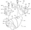
도 9a는 캡쳐장치에 의하여 위치에 고정가능하고 브레이스와 결합된 바인더, 브레이스, 스페이서, 및 신연 가이드를 갖는 본 발명에 따르는 임플란트의 실시예의 사시도이다.9A is a perspective view of an embodiment of an implant according to the present invention having a binder, a brace, a spacer, and an elongated guide that is fixable in position by a capture device and associated with a brace.
도 9b는 캡쳐장치와 브레이스 사이에 바인더를 고정하기 위하여 캡쳐장치가 배열된 경우에, 도 9a의 임플란트의 사시도이다.FIG. 9B is a perspective view of the implant of FIG. 9A when the capture device is arranged to secure the binder between the capture device and the brace. FIG.
도 9c는 도 9a와 도 9b의 임플란트의 측면도이다.9C is a side view of the implant of FIGS. 9A and 9B.
도 10a는 도 9a 및 도 9b의 임플란트의 캡쳐장치 내부에 느슨하게 위치하는 바인더의 횡단면 평면도(corss-sectional top view)이다.FIG. 10A is a cross-sectional top view of a binder loosely positioned inside the capture device of the implant of FIGS. 9A and 9B.
도 10b는 도 9a 및 도 9b의 임플란트의 캡쳐장치에 의하여 브레이스에 결합된 바인더의 횡단면 평면도이다.10B is a cross sectional plan view of a binder coupled to the brace by the capture device of the implant of FIGS. 9A and 9B.
도 10c는 도 9a 및 도 9b의 임플란트의 캡쳐장치의 양자택일적인 실시예 내부에 느슨하게 위치하는 바인더의 횡단면 평면도이고,10C is a cross-sectional plan view of a binder loosely positioned inside an alternative embodiment of the capture device of the implant of FIGS. 9A and 9B;
도 10d는 바인더가 브레이스에 결합된 경우에, 도 10c의 캡쳐장치와 바인더의 횡단면 평면도이다.10D is a cross-sectional plan view of the capture device and binder of FIG. 10C when the binder is bonded to the brace.
도 11은 인접한 가시돌기 사이에 위치하는 도 9a 및 도 9b의 임플란트의 단부도이다.11 is an end view of the implant of FIGS. 9A and 9B located between adjacent spinous processes.
도 12는 인접한 가시돌기 사이에 도 9a 내지 도 11의 임플란트를 위치시키는 방법을 설명하기 위한 블럭 선도이다.12 is a block diagram illustrating a method of placing the implant of FIGS. 9A-11 between adjacent spinous processes.
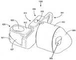
도 13a는 신연 가이드, 스페이서, 제1 날개 및 캡쳐장치를 포함하는 제2 날 개를 갖는 본 발명에 따르는 임프란트의 다른 실시예의 사시도이다.13A is a perspective view of another embodiment of an implant according to the present invention having a second wing comprising a distraction guide, a spacer, a first wing and a capture device;
도 13b는 신연 가이드, 스페이서, 제1 날개 및 캡쳐장치를 포함하는 제2 날개를 갖는 본 발명에 따르는 도 13a의 임프란트의 사시도이다.FIG. 13B is a perspective view of the implant of FIG. 13A in accordance with the present invention having a distal guide, a spacer, a first wing and a second wing comprising a capture device.
도 14는 신연 가이드, 스페이서, 제1 날개 및 캡쳐장치를 포함하는 제2 날개를 갖는 본 발명에 따르는 임프란트의 다른 실시예의 사시도이다.14 is a perspective view of another embodiment of an implant according to the present invention having a second wing comprising a distraction guide, a spacer, a first wing and a capture device.
도 15는 신연 가이드, 스페이서, 제1 날개 및 캡쳐장치를 포함하는 제2 날개를 갖는 본 발명에 따르는 임프란트의 다른 실시예의 사시도이다.15 is a perspective view of another embodiment of an implant according to the present invention having a second wing including a distraction guide, a spacer, a first wing and a capture device.
도 16은 인접한 가시돌기 사이의 도 13a 내지 도 15의 임플란트를 위치시키는 방법을 설명하기 위한 블럭 선도이다.FIG. 16 is a block diagram illustrating a method of placing the implant of FIGS. 13A-15 between adjacent spinous processes.
도 1은 미국 특허 제6,695,842호(Zucherman)와 미국 특허 제6,712,819호(Zucherman)에 개시된 임플란트의 사시도이고, 둘은 참조에 의하여 여기에 통합된다. 임플란트(100)는 본체(101)를 갖는다. 본체(101)는 스페이서(102), 제1 날개(108), 조직으로 인도된 확장자(106, lead-in tissue expander, 여기서는 신연 가이드(distraction guide)로 언급됨) 및 정렬트랙(103)을 포함한다. 본체(101)는 인접한 가시돌기(spinous process)들 사이에 삽입된다. 바람직하게, 본체(101)는 뼈 또는 인대에 결합됨이 없이 위치(소망하는 위치)에 남아있는다.1 is a perspective view of an implant disclosed in US Pat. No. 6,695,842 (Zucherman) and US Pat. No. 6,712,819 (Zucherman), both of which are incorporated herein by reference. The
신연 가이드(106)는 신연 가이드가 확장되는 첨단(tip)을 포함하며, 상기 첨단은 극돌간 인대(interspinous ligament)에 구멍을 뚫을 수 있거나 작은 초기확장구멍(small initial dilated opening)으로 삽입될 수 있도록 충분히 작은 직경을 갖는다. 신연 가이드(106)의 단면적 또는 직경은 본체(101) 및 스페이서(102)의 직경과 유사할 때까지 점진적으로 증가된다. 끝이 점점 가늘어지는 전단(tapered front end)에 의하여 의사는 인접한 가시돌기 사이에 임플란트(100)를 쉽게 압박(urge)할 수 있다. 인접한 가시돌기 사이로 임플란트(100)를 압박할 때, 신연 가이드(106)의 전단은 인접한 가시돌기들을 떼어놓고, 인접한 가시돌기 사이의 공간이 점차 스페이서(102)의 직경에 근접하도록 하기 위하여 극돌간 인대를 팽창시킨다.The
스페이서(102)의 형상은 가시돌기들 사이에 삽입될 수 있도록 마련되어 있고, 가시돌기는 스페이서(102)에 수용되도록 형상이 변경되거나 일부가 절단될 필요가 없다. 추가적으로, 연관된 인대는 잘릴 필요가 없고, 주변의 조직에 피해가 거이 없다. 도 1에 도시된 바와 같이, 스페이서(102)는 타원형의 단면을 가지며, 스페이서(102)는 스페이서(102)가 가시돌기의 비평탄면에 대하여 가자정렬할 수 있도록 하기 위하여 제1 날개(108)로부터 연장된 중심체(이하에서는 '축'이라고 기재함)에 대하여 선회할 수 있다. 자가정렬은 압축하중(compressive load)이 뼈의 면을 가로질러 분산될 수 있도록 한다. 미국 특허 제6,695,842호(Zucherman)에 고려된 바와 같이, 예을 들어, 스페이서(102)는 6mm, 8mm, 10mm, 12mm 및 14mm의 직경을 가질 수 있다. 상기 직경들은 스페이서가 가시돌기를 떨어트리고 서로 분리되도록 유지시킴에 의한 높이에 관한 것이다. 타원형으로 형성된 스페이서에 대하여, 선택된 높이(직경)은 타원을 가로지르는 작은 치수의 측정값이다. 작은 치수는 어느 하나가 다른 것의 상부에 있도록 배열된 가시돌기의 정렬에 대한 종축이다.The shape of the
제1 날개(108)는 상부(113)와 하부(113)를 갖는다. 도 1에 도시된 바와 같이, 상부(112)는 L4(L4 ~ L5 위치) 또는 L5(L5 ~ S1 위치) 척추의 가시돌기의 해부학적 형상 또는 윤곽에 적합하도록 형성되어 있다. 동일한 형상 및 상기 형상의 변형은 다른 움직이는 부분(motion segment)을 수용하기 위하여 사용된다. 하부(113)는 가시돌기를 수용하기 위하여 둥근형상으로 마련될 수 있다. 제1 날개(108)의 하부(113)와 상부(112)는 임플란트(100)가 인접한 가시돌기 사이에 삽입될 때 정지 메카니즘(stop mechanism)으로 작용한다. 임플란트(100)는 제1 날개(108)의 표면을 넘어서 삽입되지 않는다. 추가적으로, 임플란트(100)가 삽입되면, 제1 날개(108)는 임플란트(100)의 면대면(side to side) 또는 전후 운동을 방지할 수 있다. 제1 날개(108)는 본체삽입장치(미도시)의 핀(pin)을 수용하기 위한 하나 이상의 정렬구(103, alignment holes)와 하나 이상의 고정핀홀(104)을 더 포함한다. 여기서, 정렬구(103)는 정렬트랙(alignment track)을 포함한다.The
임플란트(100)는 조정날개(150, 이하에서는 제2 날개라고 한다)를 더 포함한다. 조정날개(150)는 하부(152)와 상부(153)를 포함한다. 제1 날개(108)와 유사하게, 조정날개(150)는 척추돌기 또는 판의 해부학적 형상 또는 윤곽에 수용되도록 마련되어 있다. 조정날개(150)는 잠금부재(154)에 의하여 본체(101)에 결합된다. 조정날개(150)는 정렬탭(158)을 갖는다. 조정날개(150)가 초기에 본체(101)에 위치할 때, 정렬탭(158)은 정렬트랙(103, 정렬구)과 결합한다. 정렬탭(158)은 정렬트랙(103)에 대하여 슬라이딩되며, 조정날개(150)와 제1 날개(108)가 서로 실질적으로 평행하게 유지하도록 돕는다. 본체(101)가 환자에 삽입되고 조정날개(150)가 결 합될 때, 조정날개(150)는 면대면 또는 전후방향의 움직임을 방지한다.The
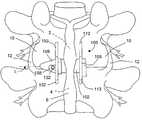
도 2a는 허리영역의 척추로부터 연장된 인접한 가시돌기 사이에 위치하는 임플란트(100)를 설명하기 위한 도면이다. 임플란트(100)는 하부 척추뼈와 연관된 상부관절돌기(12, superior articular process)와 상부 척추뼈와 연관된 아래관절돌기(10, inferior articular process) 사이에 위치한다. 극상인대(6, superspinous ligament)는 상부 및 하부 가시돌기(2, 4)와 결합된다.FIG. 2A illustrates an
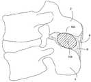
도 2b는 도 2a의 임플란트(100)의 스페이서(102) 단면을 나타낸 것이다. 스페이서(102)는 인접한 가시돌기(2, 4) 사이의 최소한의 공간을 한정한다. 펴지는 동안, 스페이서(102)는 인접한 가시돌기(2, 4) 사이의 상대적 움직임을 제한하거나 막는다. 즉, 스페이서(102)는 가시돌기(2, 4) 사이 공간의 접힘(collapse)을 제한하거나 막는다. 이러한 지지는 신경뿌리의 압박과 추간공 영역(forminal area)의 축소를 막음에 의하여 또는 추간판 탈출증(herniated disk)의 악화를 피함에 의하여 또는 다른 문제들을 경감시킴에 의하여 퇴행성 장애의 징후를 경감시킬 수 있다. 그러나, 도 2c에 도시된 바와 같이, 임플란트(100)는 굽혀질 수 있도록 하며, 몇몇의 퇴행성 장애(예를 들어 척추협착증과 같은 경우)에서 몇몇의 징후를 경감시킨다. 볼 수 있는 것처럼, 굽힘 동안 스페이서(102)는 가시돌기 사이에 떠있고, 극돌간 인대(8) 또는/및 척추와 관련된 다른 조직 및 구성에 의한 위치에 지지된다. 가시돌기(2, 4) 사이에 떠있는 능력은 또한 굽힘뿐만 아니라 회전의 정도를 변화시키도록 한다. 미국 특허 제6,695,842호(Zucherman)에 개시된 임플란트는 주요한 및 보조의 척추용융장치와 비교할 때 더 큰 수준의 움직임이 가능하다는 장점이 있다.FIG. 2B shows a cross section of the
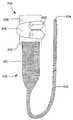
어떤 환경에서, 예를 들어 환자가 굽히거나 펼 때 통증 및 불편함을 야기하는 척추굳음증 또는 다른 퇴행성 장애가 악화되는 환경에서, 상술한 바와 같이 임플란트가 마련된 것처럼 이식의 동일 용이성이 제공되는 동안 극돌간돌기는 더 움직이지 않는 것이 바람직하다. 도 3a는 본 발명에 따르는 임플란트(300)의 실시예를 설명하기 위한 도면이다. 임플란트(300)는 신연 가이드(306)와, 스페이서(302) 및 브레이스(308)를 포함한다. 도시된 바와 같이, 다른 실시예에서 위치에 고정될 수 있음에도 불구하고, 스페이서(308)는 브레이스(302)로부터 연장된 중심체(301, 또는 축)에 대하여 회전가능하다. 바인더(330)는 바인더(330)의 근위 단부(332, proximal end)에 브레이스(308)와 확실하게 결합될 수 있다. 바인더(330)는 가요성이거나 반가요성(semi-flexible)이고, 척추의 굽힘 동안 바인더(330)가 가시돌기와 결합하기 위하여 인접한 가시돌기 주변에 위치할 수 있다. 인접한 가시돌기 주위에 바인더(330)가 위치하면, 굽힘이 제한되거나 방지되는 동안 인접한 가시돌기의 상대적 움직임을 위하여 바인더(330)가 브레이스(308)에 결합될 때 바인더(330)의 장력은 소망하는 바와 같이 설정된다.In certain circumstances, for example, in environments where spinal stiffness or other degenerative disorders, which cause pain and discomfort when the patient bends or unfolds, are exacerbated, intermittent while providing the same ease of implantation as provided for the implant as described above It is preferable that the projections do not move further. Figure 3a is a view for explaining an embodiment of the
도 3a에서 알 수 있는 바와 같이, 일 실시예에서, 브레이스(308)는 슬롯(341)을 갖는 제1 단을 포함할 수 있는데, 바인더(330)의 근위 단부(332)가 상기 슬롯(341)을 통해서 잡아 당겨지지 않도록 하기 위하여 상기 슬롯(341)을 통해서 바인더(330)의 근위 단부(332)가 꿰어지고, 봉합되고, 매듭지어 지거나, 아니면 묶일 수 있다. 다른 실시예로(미도시), 근위 단부(332)는 고리로 묶이거나, 걸쇠(clasp) 또는 다른 장치와 같은 커넥터를 포함할 수 있고, 커넥터와 결합하는 잠 금쇠(fastener)에 의하여 브레이스(308)에 고정될 수 있다. 당업자는 장력이 바인더(330)에 가해지기 위하여 바인더(330)의 근위 단부(332)는 브레이스(308)와 결합될 수 있는 수많은 방법에 대해 이해할 수 있을 것이고, 본 발명에 따르는 임플란트는 여기에 구체적으로 개시된 설명에 한정되지 않는다.As can be seen in FIG. 3A, in one embodiment, the
브레이스(308)가 가시돌기의 측면에 접촉할 때 삽입방향으로 종축(L)을 따르는 운동이 브레이스(308)에 의하여 제한되거나 방지되도록 하기 위하여 브레이스(308)는 스페이서(302)의 높이보다 더 큰 척추를 따르는 높이를 포함할 수 있다. 이런 방법으로, 브레이스(308)는 상술한 임플란트(100)의 제1 날개(108)와 유사하게 기능할 수 있다. 다른 실시예로, 브레이스(308)는 도시된 것보다 더 작거나 큰 높이를 가질 수 있다. 바인더(300)가 가시돌기의 주변에 위치하여 결합되면, 가시돌기에 대한 상대적인 임플란트(300)의 운동(예를 들어, 전후운동)은 종축(L)을 따라서뿐만 아니라 가시돌기를 따라서도 바인더(330)에 의하여 제한된다.The
바인더(330)의 자유단은 브레이스(308)에 결합된 캡쳐장치(320)에 의하여 브레이스(308)에 고정된다. 브레이스(308)는 캡쳐장치(320)로부터 연장된 플랜지(310)를 포함한다. 도 3a에 도시된 실시예에서, 캡쳐장치(320)는 잠금쇠(322)와 하나 이상의 홈(324, cut-out)을 갖는 회동캠(321)을 포함한다. 도구는 홈(324)과 한 쌍이 되고, 회동캠(324)을 선회시키기 위하여 회전한다. 회동캠(324)이 회전할 때, 회동캠(324)의 편심형상(eccentric shape)은 회동캠(324)과 플랜지(310)가 연장되어 있는 브레이스(308)의 측벽(314) 사이를 근접시키기 위한 갭(gap)을 야기한다. 바인더(330)가 격벽(314)과 회동캠(324) 사이에 위치할 때, 회동캠(324)의 회 전은 격벽(314)과 회동캠(321) 사이의 바인더(330)를 조여서 바인더(300)의 조임단(336, secured end)을 한정한다. 선택적으로, 잠금쇠(322)를 더 고정시키기 위하여, 잠금쇠(322)는 회전하여 나사로 고정하고, 그 위치에 회동캠(321)을 고정시켜 회동캠(321)에 대하여 더 꽉 조일 수 있다. 이에 더하여, 격벽(314) 및 회동캠(321) 중 적어도 하나는 회동캠(321)과 격벽(314) 사이의 바인더(330)의 미끄러짐을 방지하기 위하여 적어도 하나의 혹(knurl)이나 다른 구성(이빨 형상과 같은 것)을 포함할 수 있다. 브레이스(308)는 캡쳐장치(320)와 바인더(330)를 정렬하기 위하여 브레이스(308)의 타단에 채널이나 슬롯(도시됨)과 같은 가이드(312)를 더 포함할 수 있다.The free end of the
바인더(330)는 트랩(trap), 리본(ribbon), 밧줄(tether), 끈(cord) 또는 다른 가요성(또는 반가요성) 및, 바람직하게는 실로 꿸 수 있는 구조를 포함한다. 바인더(330)는 생체에 적합한 재료로 만들어질 수 있다. 실시예에서, 바인더(330)는 꼬여진 폴리에스테르 봉합사 재료일 수 있다. 꼬여진 폴리에스테르 봉합사 재료는, 예를 들어, 에치본드(ethibond), 에치플렉스(ethiflex), 메르실린(mersilene) 및 데이크론(dacron)을 포함할 수 있고, 비흡수성, 높은 신장성, 조직에 대한 낮은 반응성, 및 취급성이 좋은 재료이다. 다른 실시예에서, 예를 들어, 바인더(330)는 흠집 없는 스틸(외과용 스틸, surgical steel)로부터 만들어질 수 있고, 밧줄로 짜여지거나 직물이 끈으로 짜질 수도 있다. 다른 실시예에서, 바인더(330)는 비슷한 특성을 갖는 다른 재질 또는 다른 재질들의 혼합으로부터 만들어질 수 있다.The
신연 가이드(306)는, 선택적으로, 바인더(330)가 관통하여 꿰어지거나 위치 할 수 있는 신연 가이드(306)에 형성된 슬롯(slot), 보어(bore), 홈(cut-out) 또는 다른 공동(309, cavity)을 포함할 수 있다. 이러한 홈은 바인더(330)가 축 상에 위치(on-axis positioning)할 수 있게 한다(바인더는 임플란트(300)의 종축(L)에 실질적으로 정렬될 수 있다). 더욱이, 슬롯 또는 보어(bore)에 바인더(330)를 고정(capturing)하는 것은 가시돌기 사이에 임플란트(300)가 더 고정되도록 바인더(330)에 대하여 신연 가이드(306)의 이동을 방지하거나 제한할 수 있다.The
당업자에게 명확한 바와 같이, 척추의 굽힘이나 신장을 제한하거나 방지하는 임플란트를 제공하는 동안, 본 발명에 따르는 임플란트는 의사가 이식의 절차를 간소화하여 시술 소요 시간을 절감할 수 있는 장점을 제공한다. 의사는 이식에 앞서 바인더(330)의 적절한 길이를 측정할 필요 없이 인접한 가시돌기들 사이에 임플란트를 위치시키고, 가시돌기 주위의 브레이스(308)와 결합되는 바인더(330)를 위치시킬 수 있다. 캡쳐장치(320)는 바인더(330)의 일부분을 따라 바인더(330)가 브레이스(308)에 고정될 수 있도록 하며, 바인더(330)의 일부분은 근위 단부(332)와 바인더(330)의 원위 단부(334) 사이이다. 의사는 굽힘 동안 가시돌기의 소망하는 운동범위를 달성하기 위하여 브레이스(308)에 바인더(330)를 고정할 수 있다.As will be apparent to those skilled in the art, while providing an implant that limits or prevents bending or elongation of the spine, the implant according to the present invention offers the advantage that the physician can simplify the procedure of transplantation and reduce the time required for the procedure. The surgeon may position the implant between adjacent spinous processes and place the
캡쳐장치(320)와 브레이스(308)는 도 3a에 도시된 선택적인 디자인을 가질 수 있다. 본 발명의 선택적인 실시예에에 따르는 임플란트(400)의 측면도가 도 3b에 도시되어 있다. 도 3b에 도시된 임플란트(400)는 회동캠(421)을 포함하는 캡쳐장치(420)를 포함한다. 회동캠(421)은 브레이스(408)의 격벽(414)에 형성된 하나 이상의 홈(413)에 대응하는 하나 이상의 로브(lobes, 423)를 가지는 링(426)의 안 쪽에 위치한다. 바인더(330)는 캡쳐장치(420)와 브레이스(408) 사이에 위치한다. 바인더(330)가 소망한 데로 위치되면, 잠금쇠(422)와 회동캠(421)이 적당한 도구를 사용하여 회전될 수 있고, 회동캠(421)은 링(426)의 로브(423)를 브레이스(408)의 홈(413)에 맞추고, 바인더(330)의 고정단(336)이 한정되고, 일정한 위치에서 링(426)이 흔들리는 것이 방지된다. 잠금쇠(422)를 회전시키는 것은 회동챔(421)를 회전시키거나 더욱 단단히 아래 방향으로 조이게 한다. 이러한 캡쳐장치(420)는 바인더(330)가 브레이스(308)에 적절히 고정되었는지 여부에 대한 시각적 표시를 제공하고 미끄러짐을 방지한다.
다른 실시예에서, 임플란트는 도 3c 및 도 3d에 도시된 바와 같이 스프링이 장착된 메카니즘을 포함하는 캡쳐장치를 포함할 수 있다. 도 3c에는 캡쳐장치(520)를 포함하는 임플란트(500)가 개시되어 있으며, 캡쳐장치(520)는 플랜지(310)에 회전가능하게 결합되고 일방향으로 회전하도록 편향된 하나의 스프링이 장착된 회동캠(521)을 포함한다. 회동캠(521)의 회전점(pivot point)과 격벽(314) 사이의 거리는 편향된 방향으로의 회동캠(521)의 회전이 격벽(314)에 의하여 거의 차단될 수 있도록 충분히 좁다. 격벽(314)과 회동캠(521)에 사이에 바인더(330)가 꿰어지도록 하기 위하여 회동캠(521)과 격벽(314) 사이의 최대 간격은 충분히 넓어 회동캠(521)의 편심율은 크다. 의사는 스프링이 장착된 회동캠(521)의 스프링의 힘을 극복함에 의하여 회동캠(521)과 격벽(514) 사이에 바인더(330)를 위치시킬 수 있다. 바인더(330)가 정해진 위치에 위치하면, 회동캠(521)과 격벽(314) 사이의 바인더(330)를 꽉 죄기 위하여 의사는 단지 스프링이 장착된 회동캠(521)의 편향된 힘 이 격벽(314)에 대하여 회동캠(521)에 작용하도록 하기만 하면 된다. 선택적으로, 회동캠(521)과 격벽(314) 중 적어도 하나는 융기된 표면을 가지거나 미끄러짐을 방지하기 위한 구조를 가질 수 있다. 또한, 바인더(330)가 홈에 결합되기 위하여(도 3b의 로브(lob)와 홈의 정렬과 유사하게) 격벽(314)는 선택적으로 회동캠(521)을 수용하기 위한 홈(미도시)를 포함할 수 있다. 이에 따라, 미끄러짐이 제한된다.In other embodiments, the implant may include a capture device that includes a spring loaded mechanism as shown in FIGS. 3C and 3D. In FIG. 3C, an
도 3d에는 캡쳐장치(620)를 포함하는 임플란트(600)가 개시되어 있고, 캡쳐장치(620)는 스프링이 장착된 2개의 회동캠(621)을 포함한다. 여기서, 스프링이 장착된 2개의 회동캠(621)은 플랜지(310)에 회동가능하게 결합되어 있다. 보트에 로프줄을 매기 위하여 일반적으로 사용되는 캠 클리트(cam cleat)와 유사하게, 스프링이 장착된 2개의 회동캠(621)은 어느 하나가 다른 하나에 인접하도록 다른 하나의 반대편에 편향되어 있다. 회동캠(621)을 통하여 바인더(330)가 당겨짐에 의하여, 바람직하게, 바인더(330)에 장력이 인가된다. 회동캠(621)을 통하여 잡아 당겨진 바이더(330)의 힘은 바인더(330)가 꽉 조이도록 하는 편향된 힘을 극복할 수 있고, 바인더(330)의 풀림은 회동캠(621)들이 함께 선회함에 따라 바인더(330)의 고정단(336)을 한정할 수 있다. 상술한 바와 같이, 적어도 하나의 회동캠(621)은 미끄러짐을 방지하거나 제한하기 위하여 융기된 표면을 가지거나 다른 구조를 가질 수 있다.In FIG. 3D, an
여러 실시예에 따르는 임플란트는 도 3a 내지 도 3d에 어느 정도 상세하게 개시되어 있다. 그러나, 본 발명에 따르는 임플란트는 개시된 실시예들에 한정되지 않는다. 다른 형태의 복수의 캡쳐장치는 바인더의 고정단을 한정함에 의하여 브레 이스에 바인더를 고정하는 기능을 하며, 그러한 캡쳐장치는 상술한 바와 같은 회동캠을 포함하는 캡쳐장치에 한정되지 않고 다양하게 변형실시 가능하다. 캡쳐장치는 의사가 전반적인 크기 또는 예측된 크기를 갖는 바인더를 바람직한 수준의 정확한 장력으로 인접한 가시돌기의 주위에 맞추도록 하는 장치이다.Implants according to various embodiments are disclosed in some detail in FIGS. 3A-3D. However, the implant according to the present invention is not limited to the disclosed embodiments. A plurality of capture devices of another type function to fix the binder to the bracelet by defining the fixed end of the binder, and such capture device is not limited to the capture device including the rotating cam as described above, and variously modified. It is possible. The capture device is a device that allows the surgeon to fit a binder with an overall or predicted size around the adjacent spinous process with the desired level of precise tension.
도 4a 및 도 4b는 허리 부분의 척추뼈로부터 연장된 인접한 가시돌기 사이에 위치하는 도 3a의 임플란트의 반대측 단부도이다. 인접한 가시돌기 사이의 공간의 윤곽은 환자마다 다르며 움직이는 부분들마다 다르다. 회전가능한 스페이서(302)는 임플란트(300)가 가시돌기를 따라 소망하는 위치에 위치되기 위하여 공간의 형상에 최적으로 수용되도록 회전할 수 있다. 예를 들어, 향상된 지지성능을 제공하기 위하여 척추뼈의 몸통에 가능한 근접 하도록(혹은 실질적으로 척추뼈의 몸통에 근접하도록) 스페이서(302)를 위치시키는 것이 바람직하다. 소망하는 데로 임플란트(300)가 위치하면, 바이더(330)가 상부 및 하부 가시돌기(2, 4)의 주위에 정렬되기 위하여 목표로 정해진 움직이는 부분(motion segment)의 상하의 움직이는 부분(즉, 한 쌍의 인접한 척추뼈, 연관된 조직 및 구조)과 연관된 극돌간 인대를 통하도록 바인더(330)는 꿰어질 수 있다. 바인더(330)는 브레이스(308)의 슬롯(312)을 통하도록 꿰어질 수 있고, 격벽(314)과 캡쳐장치(320) 사이에 위치할 수 있다. 제1 도구(미도시)는 가시돌기(2, 4) 사이에 임플란트(300)를 삽입하기 위해 형성된 절개부(incision)에 삽입될 수 있다. 도시되지 않았으나, 스페이서(302)는 도 1의 스페이서(102)의 노치(190)와 유사한 노치를 포함할 수 있고, 브레이스(308)는 도 1의 제1 날개(108)의 홈(recess, 103, 104)과 유사한 홈(recess)을 포함할 수 있다. 스페이서(302)는 삽입되는 동안 임플란트(300)를 파지하고 풀기 위한 제1 도구(미도시)와 결합될 수 있다(미국 특허 제6,712,819호 참조. 이를 본 명세서에 참고로 포함한다). 선택적으로, 임플란트(300)를 파지하고 풀기 위한 다른 기술이 적용될 수 있다. 임플란트(300)가 소망하는 위치에 위치하고, 바인더(330)가 소망하는 데로 정렬되면, 서로 이격된 복수의 틴(tin)을 갖는 갈라져 있는 제2 도구(미도시)는 회동캠(321)을 회전시키기 위한 캡쳐장치(320)의 회동캠(321)에 결합된다. 이에 따라, 브레이스(308)에 바인더(330)가 고정된다. 필요하다면, 육각 렌치로 잠금쇠(322)를 조일 수 있다. 선택적으로, 상술한 인용발명에 기재된 바와 같이, 하나의 도구는 회동캠(321)의 회전과 임플란트(300)의 삽입 기능을 모두 수행하도록 사용될 수 있다. 선택적으로, 바인더(330)의 단부가 브레이스(308)로부터 바람직하지 않은 방향으로 연장되지 않도록 하기 위하여 바인더(330)는 트리밍될 수 있다. 알 수 있는 바와 같이, 스페이서(302)는 브레이스(308)와 신연 가이드(306)에 대하여 상대적으로 회전된다. 스페이서(302)가 브레이스(308)와 신연 가이드(306)에 대하여 상대적으로 회전하기 때문에, 브레이스(308)는 바인더(330)의 꼬임 없이 상부 및 하부 가시돌기(2, 4) 주의에 바인더(330)가 정렬되도록 위치될 수 있다. 상술한 바와 같이, 바이더(330)는 하부 가시돌기(4) 주위에 위치하고, 신연 가이드(306)의 슬롯(309)에 적어도 일부 위치하거나 꿰어지고, 바인더(330)가 브레이스(308)에 고정되기 위하여 상부 가시돌기(2) 주위에 위치한다.4A and 4B are opposite end views of the implant of FIG. 3A positioned between adjacent spinous processes extending from the vertebrae of the lumbar region. The contour of the space between adjacent spinous processes varies from patient to patient and from moving parts. The
본 발명에 따르는 임플란트는 이식 시술은 (종래 기술의 이식 시술에 비하여) 침습을 최소화하면서도 의사로 하여금 목표로 정해진 움직이는 부분의 신장 또 는 굽힘을 제한하거나 방지할 수 있게 한다. 그러나, 이러한 임플란트는 바람직하게 더 광범위한 이식 시술에 적용될 수 있다. 예를 들어, 도 4c에 도시된 바와 같이, 인접한 가시돌기(2, 4)가 바인더(330)를 수용하도록 외과적으로 수정될 수 있고, 이에 따라, 가시돌기(2, 4)에 대하여 바인더(330)가 움직이거나 미끄러지지 않도록 할 수 있다. 바인더(330)는 인접한 움직이는 부분(adjacent motion segment)의 극돌간 인대를 관통하는 것보다 각각의 극돌간 인대(2, 4)를 직접 관통하도록 꿰어진다. 가시돌기(2, 4)로부터 제거된 뼈의 양은 끈(cord) 또는 밧줄(tether)이 스트랩(strap)보다는 바인더(330)로써 사용되는 곳에서 줄어들 수 있다. 이러한 적용은 본 발명의 이식 방법 및 임플란트의 의도된 범위에 속하는 반면, 이런 적용은 뼈의 변형 때문에 이러한 임플란트를 사용하여 달성될 수 있는 모든 이점을 실현하지 못한다.The implant according to the present invention allows the surgeon to limit or prevent stretching or bending of the targeted moving part while minimizing invasion (compared to conventional implant procedures). However, such implants are preferably applicable to a wider range of implantation procedures. For example, as shown in FIG. 4C, adjacent
본 발명에 따르는 임플란트(700)의 다른 실시예는 도 5에 도시되어 있다. 이러한 실시예에서, 바인더(430)는 상부 및 하부 가시돌기(2, 4) 중 어느 하나의 주위에 배열하기 위한 스트랩(strap)으로서 형성된 제1 부분(431)을 포함하고, 이는 끈(cord)으로 형성된 제2 부분(433)까지 테이퍼지게 형성된다. 도 6a에 도시된 바와 같이, 바인더(430)가 신연 가이드(406)를 통과하도록 꿰어지면, 생체적합성 재료의 패드(436)는 바인더(430)와 결합되고(예를 들어 패드(436)의 일 영역을 통과하도록 바인더(436)를 활주 가능하게 꿴다), 바인더(308)에 의하여 인가된 하중은 가시돌기(2)의 면의 일 영역을 가로질러 분산되도록 하기 위하여 패드(436)는 각각의 가시돌기(2)와 바인더(430) 사이로 정렬될 수 있다. 도 6b를 참고하면, 바인 더(430)가 인접한 가시돌기(2, 4)에 대하여 바람직하게 배치되면, 바인더(430)는 브레이스(708)에 고정된다. 도시된 브레이스(708)는 본 발명에 따르는 임플란트와 함께 사용되기 위한 브레이스의 다른 실시예이다. 이러한 실시예에서, 브레이스(708)는 클립을 포함하며, 클립은 그것을 통하는 제1 구멍을 갖는 스프링이 장착된 버튼(721)과 버튼(721)이 위치하는 쉘(723, shell)을 포함한다. 그리고, 쉘(723)은 제2 구멍을 가진다. 의사는 제1 구멍과 제2 구멍을 정렬시키기 위하여 버튼(721)을 누른다. 바인더(430)는 구멍들을 관통하여 꿰지며, 스프링이 구멍을 오정렬시키기 위하여 버튼(721)의 누름을 해제하고, 바인더(430)를 죄어, 바인더(430)의 고정단을 한정한다.Another embodiment of an
도 6c는 본 발명에 따르는 다른 실시예의 임플란트(800)의 단부도이다. 이 실시예에서 바인더(530)는 끈(cord)을 포함할 수 있다. 상부 패드(536)와 하부 패드(538)는 활주 가능하게 바인더와 결합될 수 있고, 상부 및 하부 가시돌기(2, 4)의 일영역의 전체에 바인더(530)에 의하여 인가된 하중이 분산될 수 있도록 정렬된다. 볼 수 있는 바와 같이, 이러한 실시예는 앞에서 설명된 브레이스와 실질적으로 다른 형상을 가지는 브레이스(808)를 포함할 수 있다. 도 6c의 브레이스(808)는 당업자가 인지할 수 있도록 일 예를 도시한 것이며, 본 발명의 임플란트를 사용하기 위한 브레이스와 캡쳐장치는 다른 형상, 메카니즘 및 정렬상태를 포함할 수 있고, 본 발명의 실시예는 다양하게 변형 가능하다. 도시된 바와 같이, 브레이스(808)의 접지면은, 바인더(530)를 정렬하기 위한 가이드(812)를 형성하기 위하여 브레이스(808)의 격벽(814)을 상부단에서 테이퍼지게 형성하고 또한 하부단에서는 바인 더(530)의 근위 단부(532)를 포획하기 위한 작은 구멍(841, eyelet) 방향으로 테이퍼지게 형성함으로써, 줄어들 수 있다. 브레이스(808)는 삽입방향으로 임플란트(800)의 움직임이 브레이스(808)에 의하여 제한되거나 방지되는 정도의 작은 구멍(841)으로부터 가이드(812)까지의 높이를 포함한다.6C is an end view of an
굽힘을 제한하거나 방지하는 바인더의 사용은 종축(L)을 따르는 운동을 제한하는 추가적인 장점을 제공한다(도 3a 참조). 그러나, 본 발명에 따르는 임플란트는 삽입방향의 반대방향으로의 움직임을 제한하거나 막는 제2 날개를 선택적으로 더 포함할 수 있다. 이러한 구성의 포함은 임플란트가 신연 가이드의 슬롯으로부터 바인더가 미끄러지거나 바인더가 고정되지 않는 위치에 유지되도록 한다.The use of a binder to limit or prevent bending provides an additional advantage of limiting motion along the longitudinal axis L (see FIG. 3A). However, the implant according to the invention may optionally further comprise a second wing which restricts or prevents movement in the opposite direction of the insertion direction. Inclusion of this configuration allows the implant to remain in a position where the binder does not slip or the binder is fixed from the slot of the distraction guide.
본 발명의 실시예에 따르는 임플란트는, 도 7a에 도시된 바와 같이, 잠금쇠(454)에 의하여 임플란트(900)의 신연 가이드(406)와 결합되는 제2 날개(450)를 포함할 수 있다. 제2 날개(450)는 도 1의 제2 날개(150)와 유사하다. 제2 날개(450)는 임플란트(900)의 종축(L)을 따라 제2 날개(450)의 위치가 조정되도록 하는 정렬탭(458)과, 종축(L)을 따르는 위치에 있는 임플란트(900)에 제2 날개(450)를 부착시키는 잠금쇠(454, 예를 들어 육각 머리의 볼트)를 포함한다. 신연 가이드(406)는 정렬탭(458)에 대응하는 정렬홈(미도시)을 포함할 수 있다. 제2 날개(450)의 접촉면(455)이 소망하는 바와 같이 정렬되도록 하기 위하여, 정렬탭(458)은 정렬홈에 끼워지고 정렬홈을 따라 이동가능하다. 도시된 바와 같이, 제2 날개(450)의 접촉면(455)이 종축(L)에 수직이기 위하여 제2 날개(450)는 실질적으로 평탄하게 정렬된 접촉면을 포함한다. 그러나, 다른 실시예로, 접촉면(455)은 평 탄할 필요 없고, 상부 및 하부 가시돌기의 접촉면에 대략 대응하게 형성될 수 있다. 도시된 바와 같이, 제2 날개(450)의 상부영역(453)과 하부영역(452)은 도 1의 제1 날개(150)의 상부영역(153)과 하부영역(152)과 실질적으로 유사하게 신연 가이드(406)으로부터 연장되지 않는다. 이와 같이, 제2 날개(450)는 척추를 따르는 도 1의 제2 날개(150)의 높이보다 작은 높이(H)를 포함한다. 도 1에 도시된 것처럼 중요하게 제2 날개(450)가 신연 가이드(406)로부터 연장되지 않음에도, 제2 날개(450)를 포함함에 의하여 여러 장점이 얻어진다. 제2 날개(450)는 스페이서(302)의 상부 또는 하부로 연장된 너브(nub)를 포함한다. 이러한 제2 날개(450)는 여기서 작은 날개(winglet)로 칭하기도 한다. 척추를 따르는 도 1의 높이보다 더 작은 전체 높이를 갖는 제2 날개(450)를 포함하는 것은 바이더(330)의 정렬에 간섭받지 않고 종축을 따르는 운동이 제한될 수 있다.The implant according to the embodiment of the present invention may include a
다른 실시예로, 본 발명에 따르는 임플란트는 신연 가이드로부터 연장가능한 제2 날개(상부영역 또는/및 하부영역)를 포함할 수 있다. 이런 방법으로 임프란트의 종축을 따르는 움직임을 제한하거나 방지하기 위한 임플란트 및 장치는 이식을 간소화시키는 단일품(single piece)에 포함될 수 있다. 도 7b 및 도 7c에 도시된 바와 같이, 본 발명에 따르는 임플란트(1000)는 신연 가이드(506)의 홈에 위치되는 선택적으로 연장가능한 상부영역(553) 및 하부영역(552)를 갖는 신연 가이드(506)를 포함할 수 있다. 상부 및 하부영역(553, 552)은 너트, 매듭(knob) 또는 기어(556)가 회전하기 위하여 기어(556)와 연관되어 작동되는 다른 메카니즘을 실행시킴에 의하여 연장될 수 있다. 기어(556)의 이빨은 상부 및 하부영역(552, 553)의 이빨과 결합되고, 상부 및 하부영역(552, 553)이 삽입방향의 반대방향으로 임플란트(1000)의 운동을 제한하기 위한 작은 날개(winglet)를 형성하도록 상부 및 하부영역(553, 552)이 충분하게 연장된다. 반대방향으로 기어(556)를 회전하여 상부 및 하부영역(553, 552)을 오그라들게 할 수 있다.In another embodiment, the implant according to the present invention may comprise a second wing (upper region and / or lower region) extendable from the distraction guide. In this way, implants and devices for limiting or preventing movement along the longitudinal axis of the implant can be included in a single piece to simplify implantation. As shown in FIGS. 7B and 7C, the
양자택일적인 실시예로, 본 발명에 따르는 임플란트(1100)는 도 7d 및 도 7e에 도시된 바와 같이 스프링이 장착된 상부 또는/및 하부 영역(653, 652)을 포함할 수 있다. 이러한 실시예에서 상부 및 하부영역(653, 652)은 지느러미(fin)형상으로 마련될 수 있고, 도 7d에 도시된 바와 같이, 경사진 전면(655, 654)을 기질 수 있으며, 확장된 위치로 편향된 스프링일 수 있다. 임플란트(1100)가 인접한 가시돌기들 사이에 위치함에 따라, 가시돌기들과 이에 관련된 조직들은 상부 및 하부영역(655, 654)의 전면과 접촉할 수 있고, 도 7e에 도시된 바와 같이, 각각의 힌지점(657, 656, hinge point)에 대하여 상부 및 하부영역(653, 652)이 선회운동하며, 신연 가이드(606)에 마련된 공동(cavity)으로 접혀진다. 임플란트(1100)가 장애물을 처리하면, 신연 가이드(650)로부터 상부 및 하부영역(653, 652)이 재연장된다. 슬롯(slot) 및 핀(fin) 메카니즘(660, 661) 또는 다른 메카니즘은 확장된 위치에 상부 및 하부영역(653, 652)을 고정하고, 사선방향으로 상부 및 하부영역(653, 652)의 과도한 확장을 금지한다. 확장된 상부 및 하부영역(653, 652)은 삽입방향의 반대방향으로 임플란트(1100)의 움직임을 제한하거나 방지한다.In an alternative embodiment, the
다른 실시예에서, 본 발명에 따르는 임플란트는 임플란트의 종축을 따르는 움직임을 제한하거나 방지하기 위하여 다른 추가적인 메카니즘이 채용될 수 있다. 도 7a 내지 도 7e에 개시된 메카니즘은 이러한 임플란트를 사용하기 위한 단지 가능한 예를 나타낸 것이며, 이에 한정되지 않는다.In other embodiments, implants according to the present invention may employ other additional mechanisms to limit or prevent movement along the longitudinal axis of the implant. The mechanisms disclosed in FIGS. 7A-7E illustrate only possible examples for using such implants, but are not limited to such.
도 8은 본 발명에 따르는 임플란트의 다른 실시예를 상부에서 내려다 본 도면이다. 도 8에 따르는 임플란트(1200)는 임플란트(1200)의 종축(L)에 대하여 가시돌기가 따르는 각도로 배열된 브레이스(708)를 포함한다. 브레이스(708)는 인접한 가시돌기의 전반적인 형상에 대략 대응하도록 상기의 각도로 배열되어 있다. 그러한 전반적인 형상은, 예를 들어, 목과 가슴영역의 척추뼈로부터 연장된 가시돌기에서 공통적으로 발견된다. 임플란트(1200)는 인접한 가시돌기의 전반적인 형상에 대략 대응하는 각도로 신연 가이드(706)으로부터 연장된 제2 날개(752)를 더 포함한다. 동일한 임플란트(1200)는, 도시된 바와 같이, 어느 하나가 다른 하나 위에 위치한다. 하부 임플란트(1200)는 인접한 가시돌기의 주위에 배열되고(상부 가시돌기만이 도시됨) 신연 가이드(706)의 슬롯(309) 내부에 위치하는 바인더(330)를 포함한다. 바인더(330)는 브레이스(708)에 바인더(330)를 고정하기 위한 캡쳐장치(320)와, 바인더(330)를 캡쳐장치(320)와 함께 정렬하기 위한 브레이스(708) 상의 가이드(712)에 의하여 형성된 채널(channel)을 포함한다. 앞에서 설명된 실시예와 다르게, 브레이스의 격벽은 회동 스페이서(302)의 회전을 수용하기 위한 홈(recess, 717)을 포함한다. 양자택일적으로, 임플란트는 고정된 스페이서들을 포함할 수 있고, 예를 들어 스페이서들은 브레이스(708) 및 신연 가이드(706)와 일체로 형성될 수 있다.8 is a view from above of another embodiment of an implant according to the invention. The
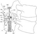
도 9a 및 도 9b는 사시도이고, 도 9c는 본 발명에 따르는 임플란트의 또 다 른 실시예의 측면도이다. 임플란트(1300)는 신연 가이드(806), 회동 스페이서(302) 및 브레이스(908)를 포함한다. 상술한 바와 같이, 바인더(330)는 바인더(330)의 몸쪽단에서 브레이스(908)와 확고하게 결합될 수 있다. 인접한 가시돌기 주위에 일단 위치하면, 바람직하게 굽힘 동안 인접한 가시돌기의 상대운동이 제한되거나 방지되기 위하여 바인더(330)가 브레이스(908)에 고정될 때 바인더(330)의 장력은 설정될 수 있다.9A and 9B are perspective views and FIG. 9C is a side view of another embodiment of an implant according to the present invention.
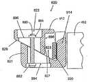
도 9a에 도시된 바와 같이, 브레이스(908)는 작은 구멍(941)을 갖는 제1 단을 포함할 수 있다. 바인더(330)의 근위 단부(332)는 작은 구멍(941)을 관통하여 꿰어질 수 있고, 실질적으로 봉합되고, 매듭지어지고 또는 묶이거나, 양자택일적으로 작은 구멍(941)을 관통하는 고리모양으로 만들어 (일례로, 버클(clasp) 등을 이용하여) 그 자신에 고정될 수 있다. 이는 바인더(330)의 몸쪽단(332)이 작은 구멍(941)을 관통하여 끌려지지 않도록 하기 위함이다. 당업자들은 장력이 바인더(330)에 인가될 수 있도록 하기 위하여 바인더(330)의 근위 단부(332)가 브레이스(908)와 결합할 수 있는 많은 다른 방법에 대해 이해할 수 있을 것이다. 앞선 실시예에서, 바인더(330)의 자유단은 브레이스(908)와 결합된 캡쳐장치(820)에 의하여 브레이스(908)에 고정될 수 있다. 도 9a 내지 도 11의 캡쳐장치(820)는 브레이스의 격벽(914)을 따라 대략 중심에 있기보다는 작은 구멍(941)의 반대편 브레이스(908)의 제2 단에 배치된다. 브레이스(908)는 선택적으로 고정핀홀(915)을 포함할 수 있고, 미국 특허 제6,712,819(Zucherman)에 개시된 바와 같이, 고정핀홀(915)은 삽입장치(미도시)의 고정핀에 의하여 결합될 수 있다. 또한, 미국특허 제6,712,819(Zucherman)에 개시된 임프란트와 유사하게, 브레이스의 격벽(914)은 선택적으로 하나 또는 그 이상의 홀들(916, 도 11참조)을 포함할 수 있다. 하나 또는 그 이상의 홀들(916, 도 11참조)은 삽입장치의 정렬핀을 수용하도록 마련되어 있다. 그리고, 브레이스의 격벽(914)은 스페이서 결합 홀(403)을 포함하는 스페이서(402)를 포함할 수 있다. 스페이서 정렬 홀(403)은 삽입장치의 스페이서 결합 핀(spacer engagement pin)을 수용하도록 마련되어 있다. 스페이서 결합 핀이 스페이서 결합 홀(403)과 결합할 때, 스페이서(402)의 회전은 제한되거나 방지된다. 일단 스페이서 결합 핀이 스페이서 결합 홀(403)으로부터 풀려지면, 스페이서(402)는 스페이서 결합 핀으로부터 저항(impedance) 없이 중심체(917)에 대하여 회전하거나 선회할 수 있다. 이러한 배치는 다른 실시예에서 스페이서(402)가 스페이서 결합 홀(403)을 포함할 필요가 없음에도 불구하고, 임플란트(1300)의 위치설정에 추가적인 제어를 의사에게 제공한다. 브레이스(908)의 제2단에 캡쳐장치(820)를 배치하는 것은 캡쳐장치(820)로부터의 간섭없이 임플란테이션에서 보조하기 위한 임플란트(1300)에 삽입도구(미국특허 제6,695,842호(Zucherman)에 개시된 형상 또는 다른 형상을 가짐)가 해제가능하게 결합하게 한다.As shown in FIG. 9A, the
임플란트(1300)의 신연 가이드(806)는 상술한 바와 같이 쐐기형상일 수 있고, 도 9a 내지 도 9c에 도시된 바와 같이 원뿔에 근접한 형상일 수도 있으며, 신연 가이드(806)를 관통하여 배치되고 이식 동안에 바인더(330)를 수용하기 위하여 개조된 슬롯(809)을 포함할 수 있다. 상술한 바와 같이, 회전가능한 스페이서(402)는 단면이 타원형일 수 있고 다른 형상일 수도 있으며, 목표로 정해진 인접한 가시 돌기들 사이의 공간의 윤곽에 대략 맞도록 신연 가이드(806)에 대하여 회전할 수 있다.The
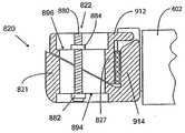
캡쳐장치(820)의 단면은 도 10a 및 도 10b에 도시되어 있다. 예를 들어, 캡쳐장치(820)는 조절가능한 잠금쇠(822)에 의하여 다른 하나와 활주 가능하게 결합하는 두 개의 부품을 포함한다. 여기서, 잠금쇠(822)는 도시된 것과 같이 6각형의 스크류일 수 있다. 캡쳐장치(820)의 고정된 부품(821)은 브레이스의 격벽(914)로부터 연장될 수 있다. 고정된 부품(821)은 경사면(823) 경사로(ramp)로 기능할 수 있다. 캡쳐장치(820)의 미끄러질 수 있는 부품(827)은 고정된 부품(821)과 활주 가능하게 결합될 수 있고, 고정된 부품(821)의 경사면(823)에 대하여 반대방향으로 위치하는 경사면(829)를 포함할 수 있다. 도시된 바와 같이, 미끄러질 수 있는 부품(827)은 조절가능한 잠금쇠(821)를 통하여 고정된 부품(821)과 결합된다. 잠금쇠(822)는 고정된 부품(821)과 미끄러질 수 있는 부품(827)의 슬롯(890, 892)에 위치할 수 있고, 꿰어진 축(880, threaded shaft), 헤드(882) 및 너트(884, nut)를 포함할 수 있다. 잠금쇠(822)의 헤드(882)는 고정된 부품(821)의 전면(894)에 결합될 수 있고, 너트(884, nut)는 미끄러질 수 있는 부품(827)의 후면에 너트(884)가 결합하기 위하여 나사 형성 축(880)에 꿰어질 수 있다. 미끄러질 수 있는 부품(827)은 너트(884)가 후면(896)에 결합하고 헤드(882)가 전면(894)에 결합할 때까지, 즉 일 방향으로 움직임이 더 방지될 때까지 고정된 부품(821)의 경사면을 따라 자유롭게 미끄러진다. 전면(894)과 후면(896) 사이의 거리는 미끄러질 수 있는 부품(827)이 경사면(823)을 따라 미끄러짐에 따라 증가하거나 감소되고, 미끄러질 수 있는 부품(827)의 고정면(898)과 브레이스의 격벽(914) 사이의 거리도 이와 같이 증가하거나 감소한다. 미끄러질 수 있는 부품(827)이 이동할 수 있는 최대거리는 너트(884)와 헤드(882) 사이의 거리에 의하여 한정된다. 의사는 너트(884)가 나사 형성 축(880)을 따라 헤드(882)로부터 더 멀리 또 근접하여 이동하도록 너트(884)를 회전함에 의하여 최대거리를 조절할 수 있고, 고정면(898)이 브레이스의 격벽(914)을 향하여 가능한 이동할 수 있다. 이에 따라, 임플란트(1300)가 가시돌기 사이에 위치할 때, 의사는 바인더(330)의 자유단을 고정면(898)과 브레이스의 격벽(914) 사이에 꿰기 위하여 최대거리를 설정할 수 있다. 도 10b에 도시된 바와 같이, 전면(894)과 후면(896)이 함께 죄어지기(urge) 위하여 의사는 잠금쇠(822)를 조정할 수 있고, 최대거리는 감소하고 고정면(898)과 브레이스의 격벽(914) 사이의 거리는 감소하며, 이에 의하여, 고정면(898)과 브레이스의 격벽(914) 사이의 바인더(330)가 죄어지고 바인더(330)의 고정단(secure end)이 한정된다. 몇몇의 실시예에서, 고정면(898) 및 브레이스의 격벽(914) 중 적어도 하나는 바인더(330)가 증가하는 장력의 아래에 위치할 때(굽힘 동안) 바인더(330)가 더 미끄러지지 않기 위한 구조를 포함할 수 있다.A cross section of the
미끄러질 수 있는 부품(827)은 선택적으로 가이드(912)가 브레이스(908)의 일 영역에 중첩되기 위하여 미끄러질 수 있는 부품(827)으로부터 연장된 가이드(912)를 선택적으로 더 포함할 수 있다. 예를 들어, 가이드(912)는 브레이스의 격벽(914)과 고정면(898) 사이의 최대거리에 대략 유사한 거리로 연장되고, 브레이스의 격벽(912)과 고정면(898) 사이에 바인더(330)가 고정되는 것을 견고하게 한 다. 다른 실시예로, 도 9a 내지 도 10b의 캡쳐장치(820)는 다른 형상 또는 외형을 포함할 수 있고, 이는 본 발명의 의도된 범위에 속한다. 예를 들어, 잠금쇠는 너트를 포함할 필요가 없다. 다른 실시예로, 도 10c 및 도 10d에 도시된 바와 같이, 잠금쇠(922)는 슬리브(984)와 결합하는 나사 형성 축(980)을 포함할 수 있다. 나사 형성 축(980)과 슬리브(984) 중 하나는 회전되고, 나사 형성 축(980)의 헤드(982)와 슬리브(984)의 헤드(985) 사이의 거리는 증가하거나 감소할 수 있다. 다른 실시예로, 잠금쇠는 나사 형성 축을 포함할 필요가 없으며, 매끄러운 축(smooth shaft)과 마찰적으로 결합하는 유지클립(retaining clip)을 갖는 매끄러운 축을 포함할 수 있다. 당업자라면 브레이스의 격벽(914)과 고정면(898) 사이의 간격을 좁히기 위하여 사용된 다양한 장치에 대해 이해할 수 있을 것이다.The
도 11은 인접한 가시돌기 사이에 위치하는 도 9a 내지 도 10d의 임플란트(1300)의 일단을 나타낸 도면이다. 도시된 바와 같이, 바인더(530)는 끈(cord)이고, 그러나 다른 실시예는 다른 외형(geometry)을 가질 수 있다. 상술한 실시예에 개시된 바와 같이, 끈(cord), 밧줄(tether) 및 이와 유사한 다른 것들이 바인더(530)로 사용될 수 있고, 바인더(530)의 장력에 의해 접촉면에 인가된 하중이 바인더(530)보다 더 넓은 접촉면의 일 영역을 가로질러 분산되도록 하기 위하여 패드(536)는 각각의 가시돌기의 접촉면을 따라 정렬될 수 있다. 이에 의하여, 사기 영역에 스트레스가 감소한다. 미끄러질 수 있는 부품(827)이 고정된 부품(821)에 대하여 뒤쪽에 위치하기 위하여 캡쳐장치(820)는 정렬될 수 있다. 잠금쇠(822)는 실질적인 후방근접을 이용하여 의사에 의하여 이용된다.FIG. 11 shows one end of the
본 발명의 도 9a 내지 도 11에 개시된 실시예에 따르는 임플란트(1300)를 외과적으로 임플란하는 방법이 도 12에 블럭 선도(block diagram)로 도시되어 있다. 상기 방법은 타겟 운동부분(target motion segment)에 절개부(incision)를 형성하는 것과, 타겟 운동부분(target motion segment)을 이용하기 위하여 절개부(incision)를 확장하는 것을 포함한다(단계 100). 목표로 정해진 인접한 가시돌기 사이의 극돌간 인대는 신연 가이드(106)로 극돌간 인대를 꿰뚫거나 치환함에 의하여 떼어지고(단계 102), 인접한 가시돌기 사이의 임플란트(1300)를 압박(urging)한다(단계 104). 극돌간 인대가 치환되면, 가시돌기 사이의 소망하는 위치를 취하기 위하여 스페이서(302)가 회전하여 가시돌기 사이에 스페이서(302)가 위치하게 된다(단계 106). 임플란트(1300)가 위치하면, 목표로 정해진 인접한 가시돌기가 바인더(330)에 의하여 형성된 루프(loop)의 안쪽에 위치하기 위하여 바인더(330)는 인접한 이동부분(adjacent spinous process)의 극돌간 인대 사이에 꿰어질 수 있다(단계 108). 의사는 브레이스의 격벽(914)과 캡쳐장치(820)의 고정면(898) 사이에 바인더(330)를 꿸 수 있다(단계 110). 바인더(330)의 소망하는 장력이 적용되면(단계 112), 바인더(330)가 브레이스의 격벽(914)과 고정면(898) 사이에 고정되기 위하여 의사는 캡쳐장치(820)의 잠금쇠(822)를 조절할 수 있다(단계 114). 이어서, 절개부를 닫는다.A method of surgically implanting an
도 13a 및 도 13b는 본 발명에 따르는 임플란트(1400)의 다른 실시예에 따르는 사시도이다. 이런 실시예에서, 임플란트(1400)는 도 1에 개시된 본체(101)에 유사한 본체(101)를 포함할 수 있다. 앞서 개시된 바와 같이, 본체(101, 여기서 제1 유닛으로 기재됨)는 스페이서(102)와, 제1 날개(108)와, 신연 가이드(106) 및 정렬트랙(103)을 포함한다. 본체(101)는 인접한 가시돌기 사이로 삽입된다. 바람직하게, 본체(101)는 뼈나 인대에 결합되지 않는 위치에 잔존한다.13A and 13B are perspective views according to another embodiment of an
정렬트랙(103)은 잠금쇠를 수용하기 위한 뀀구멍(threaded hole)을 포함한다. 정렬트랙(103)은 뀀구멍을 포함할 필요가 없으나, 추가적인 부품(종축을 따라 임플란트의 움직임을 제한하거나 방지하기 위한 제2 날개가 일예임)을 고정적으로 결합하기 위한 몇몇의 다른 메카니즘을 양자택일적으로 포함할 수 있다. 예를 들어, 양자택일적인 실시예에서, 정렬트랙(1403)은 도 15에 도시된 바와 같이, 제2 날개(1450)가 활주 가능하게 수용되기 위한 플랜지를 포함할 수 있다.
도 13a 및 도 13b에 더 자세히 도시된 바와 같이, 임플란트(1400)는 임플란트(1400)와 이동가능하게 결합할 수 있는 제2 날개(1450)를 포함한다. 제2 날개(1450)는 본체(101)의 정렬트랙(103)에 수용되도록 개조된 정렬탭(1458)을 포함하고, 정렬탭(1458)은 정렬탭(1458)이 잠금쇠와 정렬트랙(103) 사이에 위치되도록 하기 위하여 잠금쇠를 수용하기 위한 슬롯(slot)을 선택적으로 포함한다. 양자택일적인 실시예로, 정렬탭(1485)은 슬롯을 포함할 필요는 없으나, 본체(101)와 짝을 이루기 위한 몇몇의 다른 메카니즘을 포함할 수 있다.As shown in more detail in FIGS. 13A and 13B, the
제2 날개(1450)는 슬롯(또는 작은 구멍(eyelet))을 갖는 제1 단을 포함한다. 바인더(330)의 근위 단부(332)가 슬롯(1441)을 통하여 당겨질 수 없도록 하기 위하여 바인더(330)의 근위 단부(332, 여기서 고정단(anchored end)으로 언급됨)는 슬롯(1441)을 통하여 꿰어지거나, 봉합되거나, 매어지거나, 만약 그렇지 않다면 묶여 지거나, 양자택일적으로 슬롯(1441)을 통하여 고리로 매어지던지 자신에 (일례로, 걸쇠를 이용하여) 고정된다. 당업자라면 장력이 바인더(330)에 적용되기 위하여 바인더(330)의 근위 단부(332)가 제2 날개(1450)와 결합될 수 있는 많은 다른 방법에 대해 이해할 수 있을 것이다. 바인더(330)는 인접한 가시돌기 주위에 위치될 수 있고, 바인더(330)의 길이의 일 영역은 제2 날개(1450)와 결합하는 캡쳐장치(1420)에 의하여 제2 날개(1450)에 고정될 수 있다. 여기서, 바인더(330)의 길이는 바인더(330)의 근위 단부(332)로부터 연장된 바인더(330)의 일영역이다.The
도 13a 및 도 13b의 캡쳐장치(820)는 슬롯(1441)에 반대되는 제2 날개(1450)의 제2 단에 배열된다. 캡쳐장치(1420)는 도 10a 및 도 10b와 관련하여 상술된 바와 같이 캡쳐장치(1420)와 실질적으로 유사할 수 있고, 예를 들어, 조정할 수 있는 잠금쇠에 의하여 다른 하나와 활주 가능하게 결합된 2개의 부품을 포함할 수 있다. 상술한 바와 같이, 캡쳐장치의 고정부품(1421)은 제2 날개(1450)로부터 연장될 수 있다. 고정부품(1421)은 경사로(ramp)로 기능하는 경사면을 포함할 수 있다. 캡쳐장치의 미끄러질 수 있는 부품(1427)은 고정부품(1421)과 활주 가능하게 결합될 수 있고, 고정부품(1421)의 경사면에 반대로 위치하는 경사면을 포함할 수 있다. 미끄러질 수 있는 부품(1427)은 고정돈 부품(1421)의 경사면을 따라 미끄러짐에 따라, 제2 날개(1450)와 미끄러질 수 있는 부품(1427)의 고정면(1498) 사이의 거리는 증가하거나 감소한다. 상술한 바와 같이, 미끄러질 수 있는 부품(1427)은 제2 날개(1450)의 일영역과 중첩되기 위하여 미끄러질 수 있는 부품(1427)으로부터 연장된 가이드(1412)를 선택적으로 더 포함할 수 있다. 예를 들어, 가이드(1412)는 제2 날개(1450)와 고정면(1498) 사이의 최대 거리에 대략 인접하도록 거리를 연장할 수 있고, 제2 날개(1450)와 고정면(1498) 사이에 바인더(330)가 배열되는 것을 확실하게 도울 수 있다.The
의사는 바인더(330)가 인접한 가시돌기 사이에 위치되고, 제2 날개(1450)와 미끄러질 수 있는 부품(1427) 사이에 바인더(330)를 꿰기 위하여 바인더(330)를 위치시킬 수 있다. 의사는 고정면(1498)과 제2 날개(1450) 사이의 거리를 감소시키기 위하여 잠금쇠(1422)를 조절할 수 있고, 이에 따라, 제2 날개(1450)과 고정면(1498) 사이의 바인더(330)가 죄어지고 바인더(330)의 고정단이 한정된다. 몇몇의 실시예에서, 바인더(330)가 증가되는 장력의 하부에 위치할 때(굽힘 동안), 고정면(1498) 및 제2 날개(1450) 중 적어도 하나는 바인더(330)가 미끄러짐으로부터 더 방지되기 위한 구조를 포함할 수 있다.The surgeon may position the
임플란트(1400)는 본체(101)의 제1 날개(108)와 선택적으로 결합가능한 바인더 정렬부(1470)를 더 포함할 수 있다. 바인더 정렬부(1470)는 제1 날개(108)의 잠금핀홀(104, locking pin hole)에 바인더 정렬부(1470)를 단단히 묶음에 의하여 제1 날개(108)와 결합될 수 있다. 이런 실시예에서, 잠금쇠(1455)는 바인더 정렬부(1470)의 홀(1471)을 통하여 바인더 정렬부(1470)를 제1 날개(108)와 결합시키는데 사용되고, 잠금핀홀(104)은 꿰어지거나, 그렇지 않으면 잠금쇠(1455)에 수용되도록 개조될 수 있다. 잠금핀홀(104)은 삽입도구(미도시)의 잠금핀(locking pin)을 활주 가능하게 수용하기 위하여 홀로서 기능 하기 위하여 개조될 수 있고, 이에 따라, 본체(101)의 위치설정과 삽임을 용이하게 하고, 바인더 정렬부(1470)의 위치설 정을 위하여 잠금쇠(1455)를 고정적으로 수용하기 위한 기능하기 위하여 개조될 수 있다. 바인더 정렬부(1470)는 본체(101)에 바인더 정렬부(1470)를 더 확고히 고정하기 위하여 본체(101)의 정렬홀(192)에 대응하는 핀(1474)을 선택적으로 더 포함할 수 있고, 본체(101)에 대한 바인더 정렬부(1470)의 바람직하지 않은 운동을 제한한다.The
바인더 정렬부(1470)는 전후방향으로 바인더(330)의 흔들림을 제한하거나 방지하기 위하여 바인더 정렬부(1470)로부터 연장된 가이드(1472)를 포함한다. 가이드(1472)는, 도 13a에 도시된 바와 같이, 바인더(330)의 흔들림을 방지하거나 제한하기 위한 루프(loop)를 포함할 수 있고, 또는 양자택일적으로 다른 구조이거나, 닫힌구조 또는 닫히지 않은 구조를 포함할 수 있다. 이러한 구조는 바인더(330)의 적절한 위치설정을 도움에 의하여 본체(101)와 바이더(330) 사이의 바람직하지 않은 상대적인 움직임을 방지할 수 있고, 이식 시술 동안 바인더(330)의 정렬을 용이하게 한다.The
다른 실시예에서, 도 13a 및 도 13b의 캡쳐장치는 다른 형상, 윤곽, 메카니즘을 포함할 수 있고, 이는 본 발명의 의도된 범위에 속한다. 예를 들어, 다른 실시예로 도 14에 도시된 바와 같이, 플랜지(1514)는 바인더(330)가 회동캠(1521)과 제2 날개(1550) 사이에 고정되도록 하기 위하여 제2 날개(1550)로부터 연장되고, 회동캠(1521)으로부터 연장된다. 이러한 고정장치는 도 3c 및 도 3b에 개시된 바와 같은 캡쳐장치(1520)를 닮을 수 있다. 다른 실시예에서, 도 15에 도시된 바와 같이, 바인더(330)가 제2 날개(1514)와 스프링이 장착된 캠(1621) 사이에 고정되도 록 하기 위하여 스프링이 장착된 캠(1621)은 플랜지(1514)로부터 연장된다. 이러한 캡쳐장치는 도 3c 및 도 3d에 개시된 바와 같은 캡쳐장치(1520)를 닮을 수 있다. 당업자는 바인더(330)를 제2 날개(1450)에 고정하기 위한 복수의 다른 메카니즘에 대해 이해할 수 있을 것이다.In other embodiments, the capture device of FIGS. 13A and 13B may include other shapes, contours, and mechanisms, which are within the intended scope of the present invention. For example, as shown in FIG. 14 in another embodiment, the
본 발명에 따르는 시스템은 상술된 바와 같이 캡쳐장치(1420)와 선택적으로 바인더 정렬부(1470)를 포함하는 제2 날개(1450)를 포함할 수 있다. 시스템은 도 1에서 상술한 바와 같이 제2 날개(150)의 대용으로 본체(101)와 함께 사용될 수 있다. 양자택일적으로, 환자에 미리 임플란트된 본체(101)를 수정하고, 신장(extension) 뿐만 아니라 굽힘(flextion)을 추가적으로 제한하기 위하여, 예를 들어 존재하는 제2 날개(150)를 제거하고 제2 날개(150)를 시스템으로 치환함에 의하여 시스템이 선택적으로 사용될 수 있다. 이러한 시스템은 환자의 요구에 따라 임플란트를 형성하거나 형상을 바꾸도록 하여 의사에게 유가요성을 제공한다. 또한, 이러한 시스템은 다른 시술 및 다른 치료목적에 적합하도록 제조된 다양한 부품을 절감시켜 비용을 절감할 수 있다.The system according to the present invention may include a
본 발명의 도 13a 내지 도 15에 개시된 실시예에 따르는 임플란트를 임플란팅하는 외과적 방법이 도 16의 블럭 선도로 도시되어 있다. 상기 방법은 목표로 정해진 움직이는 부분에 절개부를 형성하는 단계와, 목표로 정해진 움직이는 부분에 접근하기 위하여 절개부를 확장하는 단계를 포함한다(단계 200). 목표로 정해진 인접한 가시돌기 사이의 극돌간 인대는 극돌간 인대를 신연 가이드(106)로 꿰뚫거나 치환함에 의하여 분산되고(단계 202), 임플란트(1400)를 인접한 가시돌기 사이로 가압하다(단계 204). 극돌간돌기가 치환됨에 따라, 스페이서(102)가 가시돌기 사이의 바람직한 위치를 취하기 위하여 회전되어, 스페이서(102)는 가시돌기 사이에 위치될 수 있다(단계 206). 임플란트(1400)가 일단 위치하면, 제2 날개(1450)는 신연 가이드(106)와 확고하게 결합될 수 있다(단계 208). 제2 날개(1450)와 결합된 바인더(310)는 목표로 정해진 인접한 가시돌기가 바인더(330)에 의하여 형성된 루프에 위치하기 위하여 인접한 움직이는 부분들의 극돌간 인대 사이에 꿰어질 수 있다(단계 210). 의사는 제2 날개(1450)와 캡쳐장치(1420)의 고정면 사이에 바인더(330)를 꿸 수 있다(단계 212). 바인더(330)의 바람직한 장력이 인가되면(단계 214), 의사는 바인더가 고정면(1498)과 제2 날개(1450) 사이에 바인더(330)가 고정되도록 하기 위하여 캡쳐장치(1420)의 잠금쇠(1422)를 조절할 수 있다(단계 216). 연속하여, 절개부는 닫혀진다(단계 218).The surgical method of implanting an implant according to the embodiment disclosed in FIGS. 13A-15 of the present invention is shown in the block diagram of FIG. 16. The method includes forming an incision in the targeted moving part and expanding the incision to approach the targeted moving part (step 200). The intervertebral ligament between the targeted adjacent spinous processes is dispersed by piercing or replacing the intervertebral ligament with the distraction guide 106 (step 202) and forcing the
본 발명의 임플란트에 사용되는 재료Materials Used for Implants of the Invention
몇몇의 실시예에서, 임플란트는 티타늄(titanium), 스테인리스 스틸(stainless steel), 코발트크롬(cobalt chrome), 및 이들의 합금과 같은 의학등급금속(medical grade metal) 또는 높은 강도와 생체 적합 특성을 갖는 다른 적합한 임플란트 재료로부터 제조될 수 있다. 추가적으로, 임플란트는 형상기억금속, 예를 들어 티타늄가 니켈의 혼합인 니티놀(nitinol), 으로부터 적어도 일부 제조될 수 있다. 이러한 재료는 전형적으로 방사선불투과성이고, X-ray 이미징(imaging)이나 다른 형태의 이미징(imaging)에서 나타난다. 본 발명에 따르는 임플란트 또는/및 이의 일부분은 다소 유연하거나 구부러질 수 있는 재료로부터 제조될 수 있다. 이런 실시예에서, 임플란트 또는/및 이들의 일부분은 전체적으로 또는 부분적으로 의학등급 생체적합성 중합체, 공중합체, 혼합물 및 중합체의 합성으로부터 제조될 수 있다. 공중합체는 한 종류 이상의 단량체로부터 얻어진 중합체이다. 중합체 합성물은 둘 이상의 성분이 불균일하게 혼합되어 있고, 상기 성분은 서로 섞일 수 없고, 이에 따라, 서로 간섭을 발생시킨다. 중합체 혼합물은 둘 이상의 다른 종류의 중합체로 이루어진 미시적으로 균일한 혼합물이다. 많은 중합체들, 공중합체들, 혼합물들 및 중합체 혼성물들은 방사선 투과성이고, x-ray 또는 다른 형태의 이미징(imaging) 동안에는 표시되지 않는다. 이러한 재료들을 포함하는 임플란트는 이미징(imageing) 동안에 전체적으로 방사선 투과재료를 포함하는 임플란트보다 덜 차단된 척추의 화면을 의사에게 제공한다.In some embodiments, the implant is a medical grade metal such as titanium, stainless steel, cobalt chrome, and alloys thereof or has high strength and biocompatible properties. It can be made from other suitable implant materials. Additionally, the implant can be made at least in part from a shape memory metal, such as nitinol, where titanium is a mixture of nickel. Such materials are typically radiopaque and appear in X-ray imaging or other forms of imaging. The implant according to the invention and / or portions thereof may be made from a material which is somewhat flexible or bendable. In such embodiments, the implant or / and portions thereof may be prepared in whole or in part from the synthesis of medical grade biocompatible polymers, copolymers, mixtures and polymers. Copolymers are polymers obtained from one or more types of monomers. The polymer composite is inhomogeneously mixed with two or more components, and the components cannot be mixed with each other, thus causing interference with each other. Polymer mixtures are micro homogeneous mixtures of two or more different kinds of polymers. Many polymers, copolymers, mixtures, and polymer blends are radiation transmissive and are not displayed during x-ray or other forms of imaging. Implants comprising these materials provide the physician with a screen of the spine that is less blocked than the implants that comprise the radiopaque material as a whole during imaging.
생체 적합성 중합체들의 일 그룹(one group)은 폴리에테르에테르케톤(polyetheretherketone, PEEK)을 포함하는 몇몇의 요소들과 폴리에테르케톤케톤(polyetherketoneketone, PEKK)을 갖는 폴리아릴에테르케톤(polyaryletherketone) 군이다. 폴리에테르에테르케톤(polyetheretherketone, PEEK)은 임플란트를 위한 항구성 재료로 증명되었고 생체 적합성의 기준을 충족시킨다. 의학등급 폴리에테르에테르케톤(polyetheretherketone)은 피크-옵티마(PEEK-OPTIMA)란 이름의 제품으로 영국 랭카셔 소재의 빅트렉스 코포레이션(Victrex Corporation)으로부터 입수할 수 있다. 의학등급 폴리에테르케톤케톤(polyetherketoneketone)은 옥스페크(OXPEKK)란 이름의 제품을 옥스포드 퍼포먼스 머트리얼즈(Oxford Performance Materials)와 바방바이오페크(BioPEKK)란 이름 의 제품을 쿠어스텍(CoorsTek)로부터 얻을 수 있다. 이런 의학등급재료는 강화된 중합체 수지로서 유용하고, 이러한 강화된 수지는 더 큰 재료강도를 나타낸다. 실시예에서, 임플란트는 PEEK 450G로부터 제조될 수 있고, 비충전 PEEK(unfilled PEEK)는 빅트렉스(Victrex) 회사로부터 의학적 이식에 유용하다고 승인되었다. 이 재료를 얻을 수 있는 다른 원천은 인도 파놀리(India, Panoli)에 위치하는 가다(Gharda)를 포함한다. PEEK 450G는 다음과 같은 재료 특성을 갖는다.One group of biocompatible polymers is a group of polyaryletherketones with several elements, including polyetheretherketone (PEEK) and polyetherketoneketone (PEKK). Polyetheretherketone (PEEK) has been demonstrated as a durable material for implants and meets the criteria of biocompatibility. Medical grade polyetheretherketone is available from Victrex Corporation, Lancashire, UK under the product name PEEK-OPTIMA. Medical grade polyetherketoneketone obtains a product named Oxpekk from Oxford Performance Materials and Biopekk from CoorsTek. Can be. Such medical grade materials are useful as reinforced polymer resins, and such reinforced resins exhibit greater material strength. In the examples, implants can be made from PEEK 450G and unfilled PEEK has been approved as useful for medical implants by Victrex. Other sources of this material include Gharda, located in Panoli, India. PEEK 450G has the following material properties:
PEEK 450은 적당한 물리적 기계적 특성을 가지고 인접한 가시돌기 사이의 물리적 하중을 전달하거나 유포시키기에 적합하다. 임플란트 또는/및 이의 일부분은 압출성형, 사출성형, 압축성형 및/또는 기계가공 기술에 의하여 형성될 수 있다.
선택된 재료들은 충전(fill) 될 수 있음은 물론이다. 충진제(filler)는 중합체, 공중합체, 중합체 혼합물, 또는 중합체 합성물에 중합체재료를 강화하기 위하여 추가될 수 있다. 충진제는 기계적, 광학적, 열적 특성을 수정하기 위하여 첨가된다. 예를 들어, 탄소섬유는 하중을 견디는 장치와 같은 특정용도를 위하여 강도를 향상시켜 기계적으로 중합체를 강화하기 위하여 첨가된다. 몇몇의 실시예로, PEEK의 다른 등급은 유용하고, 30%유리충진(30% glass-filled) 또는 30% 탄소충진(30% carbon-filled) 등급과 같이 본 발명에 따르는 임플란트에 사용되기 위하여 의도되었다. 그리고, 이러한 재료는 FDA나 다른 규제단체에 의하여 임플란트 장치 의 사용에 적합하다. 유리가 충진된 PEEK(glass-filled PEEK)는 확장속도를 줄이고, 충진되지 않은 PEEK와 비교하여 PEEK의 곡률탄성율이 증가한다. 산출물은 향상된 강도, 딱딱함 또는 안전성에 대하여 이상적이라고 알려져 있다. 탄소가 충진된 PEEK는 충진되지 않은 PEEK와 비교하여 향상된 압축강도, 딱딱함 및 낮은 확장속도를 가진다고 알려져 있다. 탄소가 충진된 PEEK는 또한 저항력(wear resistance)과 하중전달능력(load carrying capability)을 제공한다.Of course, the selected materials can be filled. Fillers may be added to the polymer, copolymer, polymer mixture, or polymer composite to reinforce the polymeric material. Fillers are added to modify mechanical, optical, and thermal properties. For example, carbon fiber is added to enhance strength and mechanically strengthen the polymer for certain applications, such as load bearing devices. In some embodiments, other grades of PEEK are useful and intended for use in implants according to the present invention, such as 30% glass-filled or 30% carbon-filled grades. It became. These materials are also suitable for use with implant devices by the FDA or other regulatory bodies. Glass-filled PEEK (glass-filled PEEK) reduces the expansion rate and increases the curvature modulus of PEEK compared to unfilled PEEK. The output is known to be ideal for improved strength, stiffness or safety. Carbon filled PEEK is known to have improved compressive strength, stiffness and low expansion rate compared to unfilled PEEK. Carbon-filled PEEK also provides wear resistance and load carrying capability.
이해할 수 있는 바와 같이, 다른 적당한 생체적합성 열가소성 재료 또는 열가소성 응축물은 피로를 견디고, 좋은 복원력(good memory)을 가지며, 휘거나 구부려질 수 있고, 낮은 수분흡수율, 좋은 내구성 및/또는 마모 저항성을 가지며, 본 발명의 범위에 벗어나지 않는 범위에서 사용될 수 있다. 언급한 바와 같이, 임플란트는 폴리에테르케톤케톤(polyetherketoneketone, PEKK)을 포함할 수 있다. 사용될 수 있는 다른 재료는 폴리에테르케톤(polyetherketone, PEK), 폴리에테르케톤에테르케톤케톤(polyehterketoneetherketone, PEKEKK), 폴리에테르에테르케톤케톤(polyetheretherketoneketone, PEEKK) 및 폴리아릴이써에트르케톤(polyaryletheretherketone)을 포함할 수 있다. 또한, 다른 열가소성뿐만 아니라 다른 폴리케톤(polykethone)도 사용될 수 있다. 임플란트에 사용될 수 있는 적당한 중합체에 대한 관계는 다음의 문서에 따라 제작될 수 있고, 이들은 관계에 의하여 여기서 통합된다. 상기 문서는 "생체적합성 중합체 재료"로 명칭된 PCT 공개 WO 02/00275 A1(2002년 2월 3일), "생체적합성 중합체 재료"로 명칭된 PCT 공개 WO 02/00270 A1(2002년 1월 3일)을 포함한다. Bionate®, 폴리카보네이트 우레탄(polycarbonate urethane) 등의 다른 재료는 미국 캘리포니아 버클리 소재 폴리머 테크놀로지 그룹(Polymer Technology Group) 등으로부터 얻을 수 있고, 좋은 산화안정성, 생체적합성, 기계적 강도 및 마모 저항성의 장점으로 적합하다. 다른 열가소성 재료과 다른 고분자들도 사용될 수 있다.As can be appreciated, other suitable biocompatible thermoplastics or thermoplastic condensates can withstand fatigue, have good memory, bend or bend, have low water absorption, good durability and / or wear resistance It can be used within the scope of the present invention. As mentioned, the implant may comprise polyetherketoneketone (PEKK). Other materials that can be used include polyetherketone (PEK), polyetherketoneetherketone ketone (PEKEKK), polyetheretherketoneketone (PEEKK) and polyaryletheretherketone can do. In addition, other polykethone may be used as well as other thermoplastics. Relationships to suitable polymers that can be used in the implant can be made according to the following documents, which are incorporated herein by relationship. The document discloses a PCT publication WO 02/00275 A1 (February 3, 2002) entitled "Biocompatible Polymer Material", a PCT publication WO 02/00270 A1 (January 3, 2002) "Biocompatible Polymer Material" It includes) Other materials, such as Bionate® and polycarbonate urethane, are available from the Polymer Technology Group, Berkeley, California, USA, and are suitable for their advantages of good oxidation stability, biocompatibility, mechanical strength and wear resistance. . Other thermoplastic materials and other polymers may also be used.
상술한 바와 같이, 생체적합성 재료로부터 바인더는 제조될 수 있다. 실시예에서, 바인더는 꼬아진 폴리에스테르 봉합사 재료(braided polyester suture material)로부터 제조될 수 있다. 꼬아진 폴리에스테르 봉합사 재료는, 예를 들어, 에치본드(ethibond), 에치플렉스(ethiflex), 머실린(mersilene) 및 데이크론(dacron)을 포함하고, 비흡수성이며, 높은 인장강도, 낮은 조직 반응성 및 향상된 취급성을 가진다. 다른 실시예에서, 바인더는 스테인리스 스틸(예를 들어, 외과적 스틸)로부터 제조될 수 있고, 이는 밧줄(tether)로 꼬아질 수 있고, 스트랩(strap)으로 짜여질 수 있다. 다른 실시예에서, 바인더는 유사한 특성을 갖는 몇몇의 다른 재료(또는 재료의 조합)으로부터 제조될 수 있다.As mentioned above, the binder can be made from a biocompatible material. In an embodiment, the binder can be made from braided polyester suture material. Twisted polyester suture materials include, for example, ethibond, ethiflex, mersilene and dacron, are nonabsorbent, high tensile strength, low tissue reactivity And improved handleability. In another embodiment, the binder may be made from stainless steel (eg, surgical steel), which may be twisted with a tether and woven into a strap. In other embodiments, the binder can be made from some other material (or combination of materials) with similar properties.
본 발명의 앞선 설명은 실예와 설명의 목적으로 제공된다. 이는 공개된 바와 같은 정확한 형태로 발명을 제한하거나 소모적인 의도가 아니다. 다양한 수정 및 변형이 당업자에 의하여 가능하다. 실시예들은 본 발명의 원리와 실질적인 응용을 가장 잘 설명하기 위한 순서로 기술되고 선택되었다. 이에 따라, 당업자는 본 발명의 다양한 실시예들을 이해할 수 있고, 다양한 수정들이 의도된 특정한 용도에 적 합하다. 본 발명의 범위는 다음의 청구항과 그의 균등물에 의하여 정의된다.The foregoing description of the invention is provided for purposes of illustration and description. It is not intended to be exhaustive or to limit the invention to the precise form disclosed. Various modifications and variations are possible to those skilled in the art. The embodiments have been described and selected in order to best explain the principles and practical applications of the invention. Accordingly, those skilled in the art can understand the various embodiments of the present invention, and various modifications are suitable for the specific use for which it is intended. It is intended that the scope of the invention be defined by the following claims and their equivalents.
Claims (50)
Translated fromKoreanApplications Claiming Priority (6)
| Application Number | Priority Date | Filing Date | Title |
|---|---|---|---|
| US61246504P | 2004-09-23 | 2004-09-23 | |
| US60/612,465 | 2004-09-23 | ||
| US11/095,680 | 2005-03-31 | ||
| US11/095,440US20060064165A1 (en) | 2004-09-23 | 2005-03-31 | Interspinous process implant including a binder and method of implantation |
| US11/095,440 | 2005-03-31 | ||
| US11/095,680US7909853B2 (en) | 2004-09-23 | 2005-03-31 | Interspinous process implant including a binder and method of implantation |
Publications (1)
| Publication Number | Publication Date |
|---|---|
| KR20070097412Atrue KR20070097412A (en) | 2007-10-04 |
Family
ID=36075089
Family Applications (1)
| Application Number | Title | Priority Date | Filing Date |
|---|---|---|---|
| KR1020077009238AWithdrawnKR20070097412A (en) | 2004-09-23 | 2005-09-23 | Binder-Included Implants and Implantation Methods Between Spines |
Country Status (12)
| Country | Link |
|---|---|
| US (1) | US20060064165A1 (en) |
| EP (1) | EP1804732B1 (en) |
| JP (1) | JP4667465B2 (en) |
| KR (1) | KR20070097412A (en) |
| CN (1) | CN101068513B (en) |
| AT (1) | ATE524142T1 (en) |
| AU (1) | AU2005286630A1 (en) |
| CA (1) | CA2582527A1 (en) |
| ES (1) | ES2372295T3 (en) |
| IL (1) | IL181978A0 (en) |
| MX (1) | MX2007003406A (en) |
| WO (1) | WO2006034423A2 (en) |
Cited By (1)
| Publication number | Priority date | Publication date | Assignee | Title |
|---|---|---|---|---|
| KR102070659B1 (en) | 2018-09-28 | 2020-03-02 | 명지대학교 산학협력단 | Optical microscope of probe station for preventing nanodevice damage and method of measuring electrical characteristics of nanodevice using the same |
Families Citing this family (201)
| Publication number | Priority date | Publication date | Assignee | Title |
|---|---|---|---|---|
| US20080086212A1 (en)* | 1997-01-02 | 2008-04-10 | St. Francis Medical Technologies, Inc. | Spine distraction implant |
| US7959652B2 (en)* | 2005-04-18 | 2011-06-14 | Kyphon Sarl | Interspinous process implant having deployable wings and method of implantation |
| US6068630A (en)* | 1997-01-02 | 2000-05-30 | St. Francis Medical Technologies, Inc. | Spine distraction implant |
| US8128661B2 (en)* | 1997-01-02 | 2012-03-06 | Kyphon Sarl | Interspinous process distraction system and method with positionable wing and method |
| US5836948A (en)* | 1997-01-02 | 1998-11-17 | Saint Francis Medical Technologies, Llc | Spine distraction implant and method |
| US7306628B2 (en)* | 2002-10-29 | 2007-12-11 | St. Francis Medical Technologies | Interspinous process apparatus and method with a selectably expandable spacer |
| US20080039859A1 (en)* | 1997-01-02 | 2008-02-14 | Zucherman James F | Spine distraction implant and method |
| US20080027552A1 (en)* | 1997-01-02 | 2008-01-31 | Zucherman James F | Spine distraction implant and method |
| US7201751B2 (en)* | 1997-01-02 | 2007-04-10 | St. Francis Medical Technologies, Inc. | Supplemental spine fixation device |
| US20080071378A1 (en)* | 1997-01-02 | 2008-03-20 | Zucherman James F | Spine distraction implant and method |
| US6695842B2 (en)* | 1997-10-27 | 2004-02-24 | St. Francis Medical Technologies, Inc. | Interspinous process distraction system and method with positionable wing and method |
| FR2828398B1 (en)* | 2001-08-08 | 2003-09-19 | Jean Taylor | VERTEBRA STABILIZATION ASSEMBLY |
| FR2842724B1 (en) | 2002-07-23 | 2005-05-27 | Spine Next Sa | VERTEBRAL FASTENING SYSTEM |
| FR2844179B1 (en)* | 2002-09-10 | 2004-12-03 | Jean Taylor | POSTERIOR VERTEBRAL SUPPORT KIT |
| US8147548B2 (en)* | 2005-03-21 | 2012-04-03 | Kyphon Sarl | Interspinous process implant having a thread-shaped wing and method of implantation |
| US7909853B2 (en)* | 2004-09-23 | 2011-03-22 | Kyphon Sarl | Interspinous process implant including a binder and method of implantation |
| US20060264939A1 (en)* | 2003-05-22 | 2006-11-23 | St. Francis Medical Technologies, Inc. | Interspinous process implant with slide-in distraction piece and method of implantation |
| US7833246B2 (en)* | 2002-10-29 | 2010-11-16 | Kyphon SÀRL | Interspinous process and sacrum implant and method |
| US20050075634A1 (en)* | 2002-10-29 | 2005-04-07 | Zucherman James F. | Interspinous process implant with radiolucent spacer and lead-in tissue expander |
| US8048117B2 (en) | 2003-05-22 | 2011-11-01 | Kyphon Sarl | Interspinous process implant and method of implantation |
| US7549999B2 (en)* | 2003-05-22 | 2009-06-23 | Kyphon Sarl | Interspinous process distraction implant and method of implantation |
| US20080021468A1 (en)* | 2002-10-29 | 2008-01-24 | Zucherman James F | Interspinous process implants and methods of use |
| US8070778B2 (en) | 2003-05-22 | 2011-12-06 | Kyphon Sarl | Interspinous process implant with slide-in distraction piece and method of implantation |
| US7931674B2 (en)* | 2005-03-21 | 2011-04-26 | Kyphon Sarl | Interspinous process implant having deployable wing and method of implantation |
| US7335203B2 (en)* | 2003-02-12 | 2008-02-26 | Kyphon Inc. | System and method for immobilizing adjacent spinous processes |
| US7458981B2 (en) | 2004-03-09 | 2008-12-02 | The Board Of Trustees Of The Leland Stanford Junior University | Spinal implant and method for restricting spinal flexion |
| US8523904B2 (en) | 2004-03-09 | 2013-09-03 | The Board Of Trustees Of The Leland Stanford Junior University | Methods and systems for constraint of spinous processes with attachment |
| US7585316B2 (en)* | 2004-05-21 | 2009-09-08 | Warsaw Orthopedic, Inc. | Interspinous spacer |
| US8012209B2 (en)* | 2004-09-23 | 2011-09-06 | Kyphon Sarl | Interspinous process implant including a binder, binder aligner and method of implantation |
| US8317864B2 (en) | 2004-10-20 | 2012-11-27 | The Board Of Trustees Of The Leland Stanford Junior University | Systems and methods for posterior dynamic stabilization of the spine |
| US9161783B2 (en) | 2004-10-20 | 2015-10-20 | Vertiflex, Inc. | Interspinous spacer |
| US8613747B2 (en) | 2004-10-20 | 2013-12-24 | Vertiflex, Inc. | Spacer insertion instrument |
| US9023084B2 (en) | 2004-10-20 | 2015-05-05 | The Board Of Trustees Of The Leland Stanford Junior University | Systems and methods for stabilizing the motion or adjusting the position of the spine |
| US8425559B2 (en)* | 2004-10-20 | 2013-04-23 | Vertiflex, Inc. | Systems and methods for posterior dynamic stabilization of the spine |
| US8277488B2 (en)* | 2004-10-20 | 2012-10-02 | Vertiflex, Inc. | Interspinous spacer |
| US8123782B2 (en) | 2004-10-20 | 2012-02-28 | Vertiflex, Inc. | Interspinous spacer |
| US8128662B2 (en) | 2004-10-20 | 2012-03-06 | Vertiflex, Inc. | Minimally invasive tooling for delivery of interspinous spacer |
| US8012207B2 (en) | 2004-10-20 | 2011-09-06 | Vertiflex, Inc. | Systems and methods for posterior dynamic stabilization of the spine |
| US8273108B2 (en)* | 2004-10-20 | 2012-09-25 | Vertiflex, Inc. | Interspinous spacer |
| US9119680B2 (en) | 2004-10-20 | 2015-09-01 | Vertiflex, Inc. | Interspinous spacer |
| US8409282B2 (en) | 2004-10-20 | 2013-04-02 | Vertiflex, Inc. | Systems and methods for posterior dynamic stabilization of the spine |
| US8152837B2 (en) | 2004-10-20 | 2012-04-10 | The Board Of Trustees Of The Leland Stanford Junior University | Systems and methods for posterior dynamic stabilization of the spine |
| US8167944B2 (en) | 2004-10-20 | 2012-05-01 | The Board Of Trustees Of The Leland Stanford Junior University | Systems and methods for posterior dynamic stabilization of the spine |
| US8123807B2 (en)* | 2004-10-20 | 2012-02-28 | Vertiflex, Inc. | Systems and methods for posterior dynamic stabilization of the spine |
| US8945183B2 (en)* | 2004-10-20 | 2015-02-03 | Vertiflex, Inc. | Interspinous process spacer instrument system with deployment indicator |
| US7763074B2 (en)* | 2004-10-20 | 2010-07-27 | The Board Of Trustees Of The Leland Stanford Junior University | Systems and methods for posterior dynamic stabilization of the spine |
| US9055981B2 (en) | 2004-10-25 | 2015-06-16 | Lanx, Inc. | Spinal implants and methods |
| US8241330B2 (en)* | 2007-01-11 | 2012-08-14 | Lanx, Inc. | Spinous process implants and associated methods |
| EP2219538B1 (en) | 2004-12-06 | 2022-07-06 | Vertiflex, Inc. | Spacer insertion instrument |
| US8100943B2 (en) | 2005-02-17 | 2012-01-24 | Kyphon Sarl | Percutaneous spinal implants and methods |
| US20080039944A1 (en)* | 2005-02-17 | 2008-02-14 | Malandain Hugues F | Percutaneous Spinal Implants and Methods |
| US8007521B2 (en)* | 2005-02-17 | 2011-08-30 | Kyphon Sarl | Percutaneous spinal implants and methods |
| US8029567B2 (en)* | 2005-02-17 | 2011-10-04 | Kyphon Sarl | Percutaneous spinal implants and methods |
| US20070276373A1 (en)* | 2005-02-17 | 2007-11-29 | Malandain Hugues F | Percutaneous Spinal Implants and Methods |
| US20070055237A1 (en)* | 2005-02-17 | 2007-03-08 | Edidin Avram A | Percutaneous spinal implants and methods |
| US7988709B2 (en)* | 2005-02-17 | 2011-08-02 | Kyphon Sarl | Percutaneous spinal implants and methods |
| US7998208B2 (en)* | 2005-02-17 | 2011-08-16 | Kyphon Sarl | Percutaneous spinal implants and methods |
| US8157841B2 (en)* | 2005-02-17 | 2012-04-17 | Kyphon Sarl | Percutaneous spinal implants and methods |
| US20060184248A1 (en)* | 2005-02-17 | 2006-08-17 | Edidin Avram A | Percutaneous spinal implants and methods |
| US20080288078A1 (en)* | 2005-02-17 | 2008-11-20 | Kohm Andrew C | Percutaneous spinal implants and methods |
| US8096995B2 (en)* | 2005-02-17 | 2012-01-17 | Kyphon Sarl | Percutaneous spinal implants and methods |
| US8029549B2 (en) | 2005-02-17 | 2011-10-04 | Kyphon Sarl | Percutaneous spinal implants and methods |
| US7927354B2 (en)* | 2005-02-17 | 2011-04-19 | Kyphon Sarl | Percutaneous spinal implants and methods |
| US8097018B2 (en)* | 2005-02-17 | 2012-01-17 | Kyphon Sarl | Percutaneous spinal implants and methods |
| US8057513B2 (en) | 2005-02-17 | 2011-11-15 | Kyphon Sarl | Percutaneous spinal implants and methods |
| US20070276493A1 (en) | 2005-02-17 | 2007-11-29 | Malandain Hugues F | Percutaneous spinal implants and methods |
| US20070276372A1 (en)* | 2005-02-17 | 2007-11-29 | Malandain Hugues F | Percutaneous Spinal Implants and Methods |
| US8096994B2 (en) | 2005-02-17 | 2012-01-17 | Kyphon Sarl | Percutaneous spinal implants and methods |
| US8034080B2 (en)* | 2005-02-17 | 2011-10-11 | Kyphon Sarl | Percutaneous spinal implants and methods |
| US8038698B2 (en)* | 2005-02-17 | 2011-10-18 | Kphon Sarl | Percutaneous spinal implants and methods |
| US7993342B2 (en) | 2005-02-17 | 2011-08-09 | Kyphon Sarl | Percutaneous spinal implants and methods |
| US8092459B2 (en)* | 2005-02-17 | 2012-01-10 | Kyphon Sarl | Percutaneous spinal implants and methods |
| US7998174B2 (en) | 2005-02-17 | 2011-08-16 | Kyphon Sarl | Percutaneous spinal implants and methods |
| JP2006253316A (en)* | 2005-03-09 | 2006-09-21 | Sony Corp | Solid-state imaging device |
| US8066742B2 (en)* | 2005-03-31 | 2011-11-29 | Warsaw Orthopedic, Inc. | Intervertebral prosthetic device for spinal stabilization and method of implanting same |
| US20060241757A1 (en)* | 2005-03-31 | 2006-10-26 | Sdgi Holdings, Inc. | Intervertebral prosthetic device for spinal stabilization and method of manufacturing same |
| US7862590B2 (en) | 2005-04-08 | 2011-01-04 | Warsaw Orthopedic, Inc. | Interspinous process spacer |
| US8034079B2 (en)* | 2005-04-12 | 2011-10-11 | Warsaw Orthopedic, Inc. | Implants and methods for posterior dynamic stabilization of a spinal motion segment |
| US7780709B2 (en)* | 2005-04-12 | 2010-08-24 | Warsaw Orthopedic, Inc. | Implants and methods for inter-transverse process dynamic stabilization of a spinal motion segment |
| US7789898B2 (en)* | 2005-04-15 | 2010-09-07 | Warsaw Orthopedic, Inc. | Transverse process/laminar spacer |
| US20060247638A1 (en)* | 2005-04-29 | 2006-11-02 | Sdgi Holdings, Inc. | Composite spinal fixation systems |
| US7727233B2 (en)* | 2005-04-29 | 2010-06-01 | Warsaw Orthopedic, Inc. | Spinous process stabilization devices and methods |
| DE102005028887A1 (en)* | 2005-06-22 | 2007-01-04 | Tutogen Medical Gmbh | Implant for correction of position of vertebral canal, comprises upper and lower part and made of bone substance |
| FR2887434B1 (en) | 2005-06-28 | 2008-03-28 | Jean Taylor | SURGICAL TREATMENT EQUIPMENT OF TWO VERTEBRATES |
| PL377136A1 (en) | 2005-09-19 | 2007-04-02 | Lfc Spółka Z Ograniczoną Odpowiedzialnością | Intervertebral space implant |
| FR2890850B1 (en) | 2005-09-20 | 2009-04-17 | Abbott Spine Sa | VERTEBRAL FASTENING SYSTEM |
| FR2890851B1 (en) | 2005-09-21 | 2008-06-20 | Abbott Spine Sa | ANCILLARY TO TENSION A FLEXIBLE LINK. |
| US8357181B2 (en)* | 2005-10-27 | 2013-01-22 | Warsaw Orthopedic, Inc. | Intervertebral prosthetic device for spinal stabilization and method of implanting same |
| US7862591B2 (en)* | 2005-11-10 | 2011-01-04 | Warsaw Orthopedic, Inc. | Intervertebral prosthetic device for spinal stabilization and method of implanting same |
| US20070173823A1 (en)* | 2006-01-18 | 2007-07-26 | Sdgi Holdings, Inc. | Intervertebral prosthetic device for spinal stabilization and method of implanting same |
| US8083795B2 (en)* | 2006-01-18 | 2011-12-27 | Warsaw Orthopedic, Inc. | Intervertebral prosthetic device for spinal stabilization and method of manufacturing same |
| US7691130B2 (en)* | 2006-01-27 | 2010-04-06 | Warsaw Orthopedic, Inc. | Spinal implants including a sensor and methods of use |
| US7682376B2 (en)* | 2006-01-27 | 2010-03-23 | Warsaw Orthopedic, Inc. | Interspinous devices and methods of use |
| US20070191838A1 (en)* | 2006-01-27 | 2007-08-16 | Sdgi Holdings, Inc. | Interspinous devices and methods of use |
| US7837711B2 (en)* | 2006-01-27 | 2010-11-23 | Warsaw Orthopedic, Inc. | Artificial spinous process for the sacrum and methods of use |
| US20070233068A1 (en)* | 2006-02-22 | 2007-10-04 | Sdgi Holdings, Inc. | Intervertebral prosthetic assembly for spinal stabilization and method of implanting same |
| US8262698B2 (en)* | 2006-03-16 | 2012-09-11 | Warsaw Orthopedic, Inc. | Expandable device for insertion between anatomical structures and a procedure utilizing same |
| US7985246B2 (en)* | 2006-03-31 | 2011-07-26 | Warsaw Orthopedic, Inc. | Methods and instruments for delivering interspinous process spacers |
| FR2899788B1 (en)* | 2006-04-13 | 2008-07-04 | Jean Taylor | TREATMENT EQUIPMENT FOR VERTEBRATES, COMPRISING AN INTEREPINOUS IMPLANT |
| US8118844B2 (en) | 2006-04-24 | 2012-02-21 | Warsaw Orthopedic, Inc. | Expandable device for insertion between anatomical structures and a procedure utilizing same |
| US8048118B2 (en) | 2006-04-28 | 2011-11-01 | Warsaw Orthopedic, Inc. | Adjustable interspinous process brace |
| US8252031B2 (en)* | 2006-04-28 | 2012-08-28 | Warsaw Orthopedic, Inc. | Molding device for an expandable interspinous process implant |
| US7846185B2 (en)* | 2006-04-28 | 2010-12-07 | Warsaw Orthopedic, Inc. | Expandable interspinous process implant and method of installing same |
| US8105357B2 (en)* | 2006-04-28 | 2012-01-31 | Warsaw Orthopedic, Inc. | Interspinous process brace |
| US20070270823A1 (en)* | 2006-04-28 | 2007-11-22 | Sdgi Holdings, Inc. | Multi-chamber expandable interspinous process brace |
| US8348978B2 (en)* | 2006-04-28 | 2013-01-08 | Warsaw Orthopedic, Inc. | Interosteotic implant |
| US20070270824A1 (en)* | 2006-04-28 | 2007-11-22 | Warsaw Orthopedic, Inc. | Interspinous process brace |
| US8062337B2 (en)* | 2006-05-04 | 2011-11-22 | Warsaw Orthopedic, Inc. | Expandable device for insertion between anatomical structures and a procedure utilizing same |
| US20070276496A1 (en)* | 2006-05-23 | 2007-11-29 | Sdgi Holdings, Inc. | Surgical spacer with shape control |
| US8147517B2 (en)* | 2006-05-23 | 2012-04-03 | Warsaw Orthopedic, Inc. | Systems and methods for adjusting properties of a spinal implant |
| US20070276369A1 (en)* | 2006-05-26 | 2007-11-29 | Sdgi Holdings, Inc. | In vivo-customizable implant |
| US8048119B2 (en)* | 2006-07-20 | 2011-11-01 | Warsaw Orthopedic, Inc. | Apparatus for insertion between anatomical structures and a procedure utilizing same |
| US20080086115A1 (en)* | 2006-09-07 | 2008-04-10 | Warsaw Orthopedic, Inc. | Intercostal spacer device and method for use in correcting a spinal deformity |
| FR2907329B1 (en)* | 2006-10-20 | 2009-02-27 | Jean Taylor | INTEREPINEAL VERTEBRAL PROSTHESIS |
| FR2905848B1 (en)* | 2006-09-18 | 2008-12-05 | Spineart Sa | LUMBAR INTER-SPINOUS PROSTHESIS AND ITS APPLICATIONS |
| EP2047813A1 (en) | 2007-10-11 | 2009-04-15 | Abbott Spine | Bone fixing system and method of use |
| US8845726B2 (en) | 2006-10-18 | 2014-09-30 | Vertiflex, Inc. | Dilator |
| US8162982B2 (en) | 2006-10-19 | 2012-04-24 | Simpirica Spine, Inc. | Methods and systems for constraint of multiple spine segments |
| US8029541B2 (en)* | 2006-10-19 | 2011-10-04 | Simpirica Spine, Inc. | Methods and systems for laterally stabilized constraint of spinous processes |
| US8097019B2 (en) | 2006-10-24 | 2012-01-17 | Kyphon Sarl | Systems and methods for in situ assembly of an interspinous process distraction implant |
| US20080177298A1 (en)* | 2006-10-24 | 2008-07-24 | St. Francis Medical Technologies, Inc. | Tensioner Tool and Method for Implanting an Interspinous Process Implant Including a Binder |
| FR2908035B1 (en)* | 2006-11-08 | 2009-05-01 | Jean Taylor | INTEREPINE IMPLANT |
| US20080114455A1 (en)* | 2006-11-15 | 2008-05-15 | Warsaw Orthopedic, Inc. | Rotating Interspinous Process Devices and Methods of Use |
| US7879104B2 (en)* | 2006-11-15 | 2011-02-01 | Warsaw Orthopedic, Inc. | Spinal implant system |
| US20080114357A1 (en)* | 2006-11-15 | 2008-05-15 | Warsaw Orthopedic, Inc. | Inter-transverse process spacer device and method for use in correcting a spinal deformity |
| US7955392B2 (en) | 2006-12-14 | 2011-06-07 | Warsaw Orthopedic, Inc. | Interspinous process devices and methods |
| US20080177312A1 (en)* | 2006-12-28 | 2008-07-24 | Mi4Spine, Llc | Interspinous Process Spacer Device |
| US8974496B2 (en)* | 2007-08-30 | 2015-03-10 | Jeffrey Chun Wang | Interspinous implant, tools and methods of implanting |
| US20080167655A1 (en)* | 2007-01-05 | 2008-07-10 | Jeffrey Chun Wang | Interspinous implant, tools and methods of implanting |
| US9265532B2 (en)* | 2007-01-11 | 2016-02-23 | Lanx, Inc. | Interspinous implants and methods |
| US9247968B2 (en) | 2007-01-11 | 2016-02-02 | Lanx, Inc. | Spinous process implants and associated methods |
| AU2008241447B2 (en) | 2007-04-16 | 2014-03-27 | Vertiflex, Inc. | Interspinous spacer |
| EP2142146A4 (en)* | 2007-05-01 | 2010-12-01 | Spinal Simplicity Llc | Interspinous implants and methods for implanting same |
| US8142479B2 (en)* | 2007-05-01 | 2012-03-27 | Spinal Simplicity Llc | Interspinous process implants having deployable engagement arms |
| US20080281362A1 (en)* | 2007-05-09 | 2008-11-13 | Jeremy Lemoine | Device and system for cranial support |
| US20080281361A1 (en)* | 2007-05-10 | 2008-11-13 | Shannon Marlece Vittur | Posterior stabilization and spinous process systems and methods |
| US8840646B2 (en) | 2007-05-10 | 2014-09-23 | Warsaw Orthopedic, Inc. | Spinous process implants and methods |
| US20080294200A1 (en)* | 2007-05-25 | 2008-11-27 | Andrew Kohm | Spinous process implants and methods of using the same |
| US8070779B2 (en)* | 2007-06-04 | 2011-12-06 | K2M, Inc. | Percutaneous interspinous process device and method |
| EP2182864B1 (en)* | 2007-06-22 | 2016-06-08 | Empirical Spine, Inc. | Devices for controlled flexion restriction of spinal segments |
| US20090005873A1 (en) | 2007-06-29 | 2009-01-01 | Michael Andrew Slivka | Spinous Process Spacer Hammock |
| US8348976B2 (en)* | 2007-08-27 | 2013-01-08 | Kyphon Sarl | Spinous-process implants and methods of using the same |
| US8308767B2 (en) | 2007-09-19 | 2012-11-13 | Pioneer Surgical Technology, Inc. | Interlaminar stabilization system |
| FR2921248A1 (en)* | 2007-09-25 | 2009-03-27 | Abbott Spine Sa | DEVICE FOR TIGHTENING TWO PORTIONS OF A BRAID AND INTERVERTEBRAL IMPLANT COMPRISING A BILGE, A BRAID AND A SUCH TIGHTENING DEVICE |
| US8128635B2 (en) | 2007-10-23 | 2012-03-06 | Zimmer Spine S.A.S. | Bone fixation tensioning tool and method |
| US20090118833A1 (en)* | 2007-11-05 | 2009-05-07 | Zimmer Spine, Inc. | In-situ curable interspinous process spacer |
| AU2009206098B2 (en) | 2008-01-15 | 2014-10-30 | Vertiflex, Inc. | Interspinous spacer |
| US20090198241A1 (en)* | 2008-02-04 | 2009-08-06 | Phan Christopher U | Spine distraction tools and methods of use |
| US20090198338A1 (en)* | 2008-02-04 | 2009-08-06 | Phan Christopher U | Medical implants and methods |
| US8252029B2 (en)* | 2008-02-21 | 2012-08-28 | Zimmer Gmbh | Expandable interspinous process spacer with lateral support and method for implantation |
| US8114136B2 (en)* | 2008-03-18 | 2012-02-14 | Warsaw Orthopedic, Inc. | Implants and methods for inter-spinous process dynamic stabilization of a spinal motion segment |
| US8202299B2 (en)* | 2008-03-19 | 2012-06-19 | Collabcom II, LLC | Interspinous implant, tools and methods of implanting |
| ATE515239T1 (en) | 2008-04-24 | 2011-07-15 | Zimmer Spine | SYSTEM FOR STABILIZING AT LEAST ONE SECTION OF THE SPINE |
| EP2303163B1 (en) | 2008-05-20 | 2011-11-23 | Zimmer Spine | System for stabilizing at least three vertebrae |
| EP2296567B1 (en)* | 2008-06-06 | 2014-03-12 | Simpirica Spine, Inc. | Apparatus for locking a band |
| WO2009149414A1 (en)* | 2008-06-06 | 2009-12-10 | Simpirica Spine, Inc. | Methods and apparatus for locking a band |
| US20100030549A1 (en)* | 2008-07-31 | 2010-02-04 | Lee Michael M | Mobile device having human language translation capability with positional feedback |
| US20100094344A1 (en)* | 2008-10-14 | 2010-04-15 | Kyphon Sarl | Pedicle-Based Posterior Stabilization Members and Methods of Use |
| US20100106252A1 (en)* | 2008-10-29 | 2010-04-29 | Kohm Andrew C | Spinal implants having multiple movable members |
| US8114131B2 (en)* | 2008-11-05 | 2012-02-14 | Kyphon Sarl | Extension limiting devices and methods of use for the spine |
| US8114135B2 (en)* | 2009-01-16 | 2012-02-14 | Kyphon Sarl | Adjustable surgical cables and methods for treating spinal stenosis |
| JP5475291B2 (en)* | 2009-01-20 | 2014-04-16 | アルフレッサファーマ株式会社 | Fastening aid for bone fastening cable |
| US9757164B2 (en) | 2013-01-07 | 2017-09-12 | Spinal Simplicity Llc | Interspinous process implant having deployable anchor blades |
| US8945184B2 (en)* | 2009-03-13 | 2015-02-03 | Spinal Simplicity Llc. | Interspinous process implant and fusion cage spacer |
| US9861399B2 (en) | 2009-03-13 | 2018-01-09 | Spinal Simplicity, Llc | Interspinous process implant having a body with a removable end portion |
| US20100286701A1 (en)* | 2009-05-08 | 2010-11-11 | Kyphon Sarl | Distraction tool for distracting an interspinous space |
| US8372117B2 (en)* | 2009-06-05 | 2013-02-12 | Kyphon Sarl | Multi-level interspinous implants and methods of use |
| US8157842B2 (en)* | 2009-06-12 | 2012-04-17 | Kyphon Sarl | Interspinous implant and methods of use |
| US20110077686A1 (en)* | 2009-09-29 | 2011-03-31 | Kyphon Sarl | Interspinous process implant having a compliant spacer |
| US8771317B2 (en)* | 2009-10-28 | 2014-07-08 | Warsaw Orthopedic, Inc. | Interspinous process implant and method of implantation |
| US8740948B2 (en) | 2009-12-15 | 2014-06-03 | Vertiflex, Inc. | Spinal spacer for cervical and other vertebra, and associated systems and methods |
| GB0922614D0 (en)* | 2009-12-23 | 2010-02-10 | Butterfield Forbes | Device |
| FR2954905B1 (en) | 2010-01-06 | 2012-12-28 | Implanet | DEVICE FOR FIXING VERTEBRAL |
| US8317831B2 (en)* | 2010-01-13 | 2012-11-27 | Kyphon Sarl | Interspinous process spacer diagnostic balloon catheter and methods of use |
| US8114132B2 (en)* | 2010-01-13 | 2012-02-14 | Kyphon Sarl | Dynamic interspinous process device |
| US20110172720A1 (en)* | 2010-01-13 | 2011-07-14 | Kyphon Sarl | Articulating interspinous process clamp |
| US8147526B2 (en) | 2010-02-26 | 2012-04-03 | Kyphon Sarl | Interspinous process spacer diagnostic parallel balloon catheter and methods of use |
| US8623024B2 (en) | 2010-03-12 | 2014-01-07 | Southern Spine, Llc | Implantation tools for interspinous process spacing device |
| US20110264221A1 (en)* | 2010-04-24 | 2011-10-27 | Custom Spine, Inc. | Interspinous Fusion Device and Method |
| US8814908B2 (en) | 2010-07-26 | 2014-08-26 | Warsaw Orthopedic, Inc. | Injectable flexible interspinous process device system |
| US8496689B2 (en) | 2011-02-23 | 2013-07-30 | Farzad Massoudi | Spinal implant device with fusion cage and fixation plates and method of implanting |
| US8562650B2 (en) | 2011-03-01 | 2013-10-22 | Warsaw Orthopedic, Inc. | Percutaneous spinous process fusion plate assembly and method |
| US8425560B2 (en) | 2011-03-09 | 2013-04-23 | Farzad Massoudi | Spinal implant device with fixation plates and lag screws and method of implanting |
| US8591548B2 (en) | 2011-03-31 | 2013-11-26 | Warsaw Orthopedic, Inc. | Spinous process fusion plate assembly |
| US8591549B2 (en) | 2011-04-08 | 2013-11-26 | Warsaw Orthopedic, Inc. | Variable durometer lumbar-sacral implant |
| FR2977139B1 (en) | 2011-06-30 | 2014-08-22 | Ldr Medical | INTER-SPINAL IMPLANT AND IMPLANTATION INSTRUMENT |
| US11812923B2 (en) | 2011-10-07 | 2023-11-14 | Alan Villavicencio | Spinal fixation device |
| US20130103086A1 (en)* | 2011-10-19 | 2013-04-25 | Warsaw Orthopedic, Inc. | Spinous process mounted spinal implant |
| US9622786B2 (en)* | 2012-01-09 | 2017-04-18 | Apifix Ltd. | Spinal cage |
| ES2628444T3 (en)* | 2012-02-17 | 2017-08-02 | Medacta International S.A. | Intervertebral implant with improved clamping system for the fixation plate |
| US9907671B2 (en)* | 2012-11-16 | 2018-03-06 | In Queue Innovations, Llc | Oblique expanding fusion cage device and method |
| US9668786B2 (en) | 2012-11-16 | 2017-06-06 | Southern Spine, Llc | Linkage systems for interspinous process spacing device |
| JP6373878B2 (en) | 2013-02-14 | 2018-08-15 | メダクタ・インターナショナル・ソシエテ・アノニム | Intervertebral implant with improved fixation plate shape |
| US9675303B2 (en) | 2013-03-15 | 2017-06-13 | Vertiflex, Inc. | Visualization systems, instruments and methods of using the same in spinal decompression procedures |
| CN105682613B (en)* | 2013-06-14 | 2018-06-08 | 脊椎简易矫治有限责任公司 | Interspinous process implant with the engagement arm driven by pin |
| FR3012032B1 (en) | 2013-10-18 | 2015-12-11 | Implanet | DEVICE AND SYSTEM FOR VERTICAL FASTENING FOR HOLDING A VERTEBRA ON A ROD, METHOD OF BLOCKING A LOOP WITH SUCH A DEVICE. |
| AU2015256024B2 (en) | 2014-05-07 | 2020-03-05 | Vertiflex, Inc. | Spinal nerve decompression systems, dilation systems, and methods of using the same |
| WO2023158581A1 (en) | 2022-02-15 | 2023-08-24 | Boston Scientific Neuromodulation Corporation | Interspinous spacer and systems utilizing the interspinous spacer |
| US12133664B2 (en) | 2022-12-13 | 2024-11-05 | Spinal Simplicity, Llc | Medical implant |
| US12433646B2 (en) | 2023-02-21 | 2025-10-07 | Boston Scientific Neuromodulation Corporation | Interspinous spacer with actuator locking arrangements and methods and systems |
| US12390340B2 (en) | 2023-03-15 | 2025-08-19 | Boston Scientific Neuromodulation Corporation | Interspinous spacer with a range of deployment positions and methods and systems |
Family Cites Families (89)
| Publication number | Priority date | Publication date | Assignee | Title |
|---|---|---|---|---|
| US2677369A (en)* | 1952-03-26 | 1954-05-04 | Fred L Knowles | Apparatus for treatment of the spinal column |
| US3648691A (en)* | 1970-02-24 | 1972-03-14 | Univ Colorado State Res Found | Method of applying vertebral appliance |
| US3678542A (en)* | 1970-06-17 | 1972-07-25 | Ancra Corp | Cam buckle |
| US4011602A (en)* | 1975-10-06 | 1977-03-15 | Battelle Memorial Institute | Porous expandable device for attachment to bone tissue |
| PL114098B1 (en)* | 1978-04-14 | 1981-01-31 | Wyzsza Szkola Inzynierska | Apparatus for correcting spinal curvature |
| US4554914A (en)* | 1983-10-04 | 1985-11-26 | Kapp John P | Prosthetic vertebral body |
| GB8333442D0 (en)* | 1983-12-15 | 1984-01-25 | Showell A W Sugicraft Ltd | Devices for spinal fixation |
| US4604995A (en)* | 1984-03-30 | 1986-08-12 | Stephens David C | Spinal stabilizer |
| US4643178A (en)* | 1984-04-23 | 1987-02-17 | Fabco Medical Products, Inc. | Surgical wire and method for the use thereof |
| US4573454A (en)* | 1984-05-17 | 1986-03-04 | Hoffman Gregory A | Spinal fixation apparatus |
| SE458417B (en)* | 1985-08-15 | 1989-04-03 | Sven Olerud | FIXING INSTRUMENTS PROVIDED FOR USE IN SPINE OPERATIONS |
| FR2623085B1 (en)* | 1987-11-16 | 1992-08-14 | Breard Francis | SURGICAL IMPLANT TO LIMIT THE RELATIVE MOVEMENT OF VERTEBRES |
| GB8825909D0 (en)* | 1988-11-04 | 1988-12-07 | Showell A W Sugicraft Ltd | Pedicle engaging means |
| US5201734A (en)* | 1988-12-21 | 1993-04-13 | Zimmer, Inc. | Spinal locking sleeve assembly |
| FR2642645B1 (en)* | 1989-02-03 | 1992-08-14 | Breard Francis | FLEXIBLE INTERVERTEBRAL STABILIZER AND METHOD AND APPARATUS FOR CONTROLLING ITS VOLTAGE BEFORE PLACEMENT ON THE RACHIS |
| US5047055A (en)* | 1990-12-21 | 1991-09-10 | Pfizer Hospital Products Group, Inc. | Hydrogel intervertebral disc nucleus |
| FR2693364B1 (en)* | 1992-07-07 | 1995-06-30 | Erpios Snc | INTERVERTEBRAL PROSTHESIS FOR STABILIZING ROTATORY AND FLEXIBLE-EXTENSION CONSTRAINTS. |
| GB9217578D0 (en)* | 1992-08-19 | 1992-09-30 | Surgicarft Ltd | Surgical implants,etc |
| US5356412A (en)* | 1992-10-09 | 1994-10-18 | United States Surgical Corporation | Sternum buckle with rotational engagement and method of closure |
| ATE206602T1 (en)* | 1992-11-12 | 2001-10-15 | Neville Alleyne | DEVICE FOR PROTECTING THE HEART |
| US5306275A (en)* | 1992-12-31 | 1994-04-26 | Bryan Donald W | Lumbar spine fixation apparatus and method |
| US5540703A (en)* | 1993-01-06 | 1996-07-30 | Smith & Nephew Richards Inc. | Knotted cable attachment apparatus formed of braided polymeric fibers |
| US5496318A (en)* | 1993-01-08 | 1996-03-05 | Advanced Spine Fixation Systems, Inc. | Interspinous segmental spine fixation device |
| US5415661A (en)* | 1993-03-24 | 1995-05-16 | University Of Miami | Implantable spinal assist device |
| US5360430A (en)* | 1993-07-29 | 1994-11-01 | Lin Chih I | Intervertebral locking device |
| US5454812A (en)* | 1993-11-12 | 1995-10-03 | Lin; Chih-I | Spinal clamping device having multiple distance adjusting strands |
| FR2721501B1 (en)* | 1994-06-24 | 1996-08-23 | Fairant Paulette | Prostheses of the vertebral articular facets. |
| FR2722980B1 (en)* | 1994-07-26 | 1996-09-27 | Samani Jacques | INTERTEPINOUS VERTEBRAL IMPLANT |
| ATE203885T1 (en)* | 1994-09-08 | 2001-08-15 | Stryker Technologies Corp | HYDROGEL DISC CORE |
| JPH10507386A (en)* | 1994-10-17 | 1998-07-21 | レイメディカ, インコーポレイテッド | Artificial spinal disc nucleus |
| FR2728159B1 (en)* | 1994-12-16 | 1997-06-27 | Tornier Sa | ELASTIC DISC PROSTHESIS |
| US5690649A (en)* | 1995-12-05 | 1997-11-25 | Li Medical Technologies, Inc. | Anchor and anchor installation tool and method |
| US5810815A (en)* | 1996-09-20 | 1998-09-22 | Morales; Jose A. | Surgical apparatus for use in the treatment of spinal deformities |
| US6451019B1 (en)* | 1998-10-20 | 2002-09-17 | St. Francis Medical Technologies, Inc. | Supplemental spine fixation device and method |
| US6695842B2 (en)* | 1997-10-27 | 2004-02-24 | St. Francis Medical Technologies, Inc. | Interspinous process distraction system and method with positionable wing and method |
| US6068630A (en)* | 1997-01-02 | 2000-05-30 | St. Francis Medical Technologies, Inc. | Spine distraction implant |
| US7201751B2 (en)* | 1997-01-02 | 2007-04-10 | St. Francis Medical Technologies, Inc. | Supplemental spine fixation device |
| US20020143331A1 (en)* | 1998-10-20 | 2002-10-03 | Zucherman James F. | Inter-spinous process implant and method with deformable spacer |
| US5836948A (en)* | 1997-01-02 | 1998-11-17 | Saint Francis Medical Technologies, Llc | Spine distraction implant and method |
| US5860977A (en)* | 1997-01-02 | 1999-01-19 | Saint Francis Medical Technologies, Llc | Spine distraction implant and method |
| US6022376A (en)* | 1997-06-06 | 2000-02-08 | Raymedica, Inc. | Percutaneous prosthetic spinal disc nucleus and method of manufacture |
| EP1867293A2 (en)* | 1997-10-27 | 2007-12-19 | St. Francis Medical Technologies, Inc. | Spine distraction implant |
| FR2774581B1 (en)* | 1998-02-10 | 2000-08-11 | Dimso Sa | INTEREPINOUS STABILIZER TO BE ATTACHED TO SPINOUS APOPHYSIS OF TWO VERTEBRES |
| FR2775183B1 (en)* | 1998-02-20 | 2000-08-04 | Jean Taylor | INTER-SPINOUS PROSTHESIS |
| US6352537B1 (en)* | 1998-09-17 | 2002-03-05 | Electro-Biology, Inc. | Method and apparatus for spinal fixation |
| FR2799640B1 (en)* | 1999-10-15 | 2002-01-25 | Spine Next Sa | IMPLANT INTERVETEBRAL |
| US6293949B1 (en)* | 2000-03-01 | 2001-09-25 | Sdgi Holdings, Inc. | Superelastic spinal stabilization system and method |
| US6402750B1 (en)* | 2000-04-04 | 2002-06-11 | Spinlabs, Llc | Devices and methods for the treatment of spinal disorders |
| FR2811540B1 (en)* | 2000-07-12 | 2003-04-25 | Spine Next Sa | IMPORTING INTERVERTEBRAL IMPLANT |
| JP2002095672A (en)* | 2000-09-22 | 2002-04-02 | Showa Ika Kohgyo Co Ltd | Instrument for joining bone and its joining component |
| US6579319B2 (en)* | 2000-11-29 | 2003-06-17 | Medicinelodge, Inc. | Facet joint replacement |
| FR2818530B1 (en)* | 2000-12-22 | 2003-10-31 | Spine Next Sa | INTERVERTEBRAL IMPLANT WITH DEFORMABLE SHIM |
| US6364883B1 (en)* | 2001-02-23 | 2002-04-02 | Albert N. Santilli | Spinous process clamp for spinal fusion and method of operation |
| FR2822051B1 (en)* | 2001-03-13 | 2004-02-27 | Spine Next Sa | INTERVERTEBRAL IMPLANT WITH SELF-LOCKING ATTACHMENT |
| US6582433B2 (en)* | 2001-04-09 | 2003-06-24 | St. Francis Medical Technologies, Inc. | Spine fixation device and method |
| SK1002004A3 (en)* | 2001-08-20 | 2004-08-03 | Synthes Ag | Interspinal prosthesis |
| US6678046B2 (en)* | 2001-08-28 | 2004-01-13 | Therma-Wave, Inc. | Detector configurations for optical metrology |
| FR2832917B1 (en)* | 2001-11-30 | 2004-09-24 | Spine Next Sa | ELASTICALLY DEFORMABLE INTERVERTEBRAL IMPLANT |
| US6733534B2 (en)* | 2002-01-29 | 2004-05-11 | Sdgi Holdings, Inc. | System and method for spine spacing |
| JP3708883B2 (en)* | 2002-02-08 | 2005-10-19 | 昭和医科工業株式会社 | Vertebral space retainer |
| EP1346708A1 (en)* | 2002-03-20 | 2003-09-24 | A-Spine Holding Group Corp. | Three-hooked device for fixing spinal column |
| US7048736B2 (en)* | 2002-05-17 | 2006-05-23 | Sdgi Holdings, Inc. | Device for fixation of spinous processes |
| FR2844179B1 (en)* | 2002-09-10 | 2004-12-03 | Jean Taylor | POSTERIOR VERTEBRAL SUPPORT KIT |
| US7833246B2 (en)* | 2002-10-29 | 2010-11-16 | Kyphon SÀRL | Interspinous process and sacrum implant and method |
| US8048117B2 (en)* | 2003-05-22 | 2011-11-01 | Kyphon Sarl | Interspinous process implant and method of implantation |
| US7549999B2 (en)* | 2003-05-22 | 2009-06-23 | Kyphon Sarl | Interspinous process distraction implant and method of implantation |
| US6723126B1 (en)* | 2002-11-01 | 2004-04-20 | Sdgi Holdings, Inc. | Laterally expandable cage |
| FR2851154B1 (en)* | 2003-02-19 | 2006-07-07 | Sdgi Holding Inc | INTER-SPINOUS DEVICE FOR BRAKING THE MOVEMENTS OF TWO SUCCESSIVE VERTEBRATES, AND METHOD FOR MANUFACTURING THE SAME THEREOF |
| US20050165398A1 (en)* | 2004-01-26 | 2005-07-28 | Reiley Mark A. | Percutaneous spine distraction implant systems and methods |
| US8636802B2 (en)* | 2004-03-06 | 2014-01-28 | DePuy Synthes Products, LLC | Dynamized interspinal implant |
| US7763073B2 (en)* | 2004-03-09 | 2010-07-27 | Depuy Spine, Inc. | Posterior process dynamic spacer |
| US7507241B2 (en)* | 2004-04-05 | 2009-03-24 | Expanding Orthopedics Inc. | Expandable bone device |
| US7776091B2 (en)* | 2004-06-30 | 2010-08-17 | Depuy Spine, Inc. | Adjustable posterior spinal column positioner |
| US20060015181A1 (en)* | 2004-07-19 | 2006-01-19 | Biomet Merck France (50% Interest) | Interspinous vertebral implant |
| WO2006041963A2 (en)* | 2004-10-05 | 2006-04-20 | Abdou M S | Devices and methods for inter-vertebral orthopedic device placement |
| US8123807B2 (en)* | 2004-10-20 | 2012-02-28 | Vertiflex, Inc. | Systems and methods for posterior dynamic stabilization of the spine |
| US8317864B2 (en)* | 2004-10-20 | 2012-11-27 | The Board Of Trustees Of The Leland Stanford Junior University | Systems and methods for posterior dynamic stabilization of the spine |
| US8012207B2 (en)* | 2004-10-20 | 2011-09-06 | Vertiflex, Inc. | Systems and methods for posterior dynamic stabilization of the spine |
| US8167944B2 (en)* | 2004-10-20 | 2012-05-01 | The Board Of Trustees Of The Leland Stanford Junior University | Systems and methods for posterior dynamic stabilization of the spine |
| US8162985B2 (en)* | 2004-10-20 | 2012-04-24 | The Board Of Trustees Of The Leland Stanford Junior University | Systems and methods for posterior dynamic stabilization of the spine |
| US9023084B2 (en)* | 2004-10-20 | 2015-05-05 | The Board Of Trustees Of The Leland Stanford Junior University | Systems and methods for stabilizing the motion or adjusting the position of the spine |
| US20060089719A1 (en)* | 2004-10-21 | 2006-04-27 | Trieu Hai H | In situ formation of intervertebral disc implants |
| US7918875B2 (en)* | 2004-10-25 | 2011-04-05 | Lanx, Inc. | Interspinous distraction devices and associated methods of insertion |
| EP1807012B1 (en)* | 2004-10-25 | 2016-07-06 | Lanx, LLC | Nterspinous distraction devices |
| US20060106381A1 (en)* | 2004-11-18 | 2006-05-18 | Ferree Bret A | Methods and apparatus for treating spinal stenosis |
| WO2006058221A2 (en)* | 2004-11-24 | 2006-06-01 | Abdou Samy M | Devices and methods for inter-vertebral orthopedic device placement |
| US8038698B2 (en)* | 2005-02-17 | 2011-10-18 | Kphon Sarl | Percutaneous spinal implants and methods |
| US20060195102A1 (en)* | 2005-02-17 | 2006-08-31 | Malandain Hugues F | Apparatus and method for treatment of spinal conditions |
| US20060184248A1 (en)* | 2005-02-17 | 2006-08-17 | Edidin Avram A | Percutaneous spinal implants and methods |
- 2005
- 2005-03-31USUS11/095,440patent/US20060064165A1/ennot_activeAbandoned
- 2005-09-23CNCN2005800401858Apatent/CN101068513B/ennot_activeExpired - Fee Related
- 2005-09-23JPJP2007533639Apatent/JP4667465B2/ennot_activeExpired - Fee Related
- 2005-09-23AUAU2005286630Apatent/AU2005286630A1/ennot_activeAbandoned
- 2005-09-23WOPCT/US2005/034057patent/WO2006034423A2/enactiveApplication Filing
- 2005-09-23KRKR1020077009238Apatent/KR20070097412A/ennot_activeWithdrawn
- 2005-09-23CACA002582527Apatent/CA2582527A1/ennot_activeAbandoned
- 2005-09-23MXMX2007003406Apatent/MX2007003406A/ennot_activeApplication Discontinuation
- 2005-09-23EPEP05798791Apatent/EP1804732B1/ennot_activeExpired - Lifetime
- 2005-09-23ATAT05798791Tpatent/ATE524142T1/ennot_activeIP Right Cessation
- 2005-09-23ESES05798791Tpatent/ES2372295T3/ennot_activeExpired - Lifetime
- 2007
- 2007-03-15ILIL181978Apatent/IL181978A0/enunknown
Cited By (1)
| Publication number | Priority date | Publication date | Assignee | Title |
|---|---|---|---|---|
| KR102070659B1 (en) | 2018-09-28 | 2020-03-02 | 명지대학교 산학협력단 | Optical microscope of probe station for preventing nanodevice damage and method of measuring electrical characteristics of nanodevice using the same |
Also Published As
| Publication number | Publication date |
|---|---|
| MX2007003406A (en) | 2007-05-10 |
| JP4667465B2 (en) | 2011-04-13 |
| AU2005286630A1 (en) | 2006-03-30 |
| CA2582527A1 (en) | 2006-03-30 |
| WO2006034423A3 (en) | 2006-06-01 |
| AU2005286630A2 (en) | 2006-03-30 |
| EP1804732B1 (en) | 2011-09-14 |
| EP1804732A4 (en) | 2010-06-23 |
| CN101068513A (en) | 2007-11-07 |
| WO2006034423A2 (en) | 2006-03-30 |
| ES2372295T3 (en) | 2012-01-18 |
| IL181978A0 (en) | 2007-07-04 |
| JP2008514289A (en) | 2008-05-08 |
| CN101068513B (en) | 2010-05-05 |
| ATE524142T1 (en) | 2011-09-15 |
| EP1804732A2 (en) | 2007-07-11 |
| US20060064165A1 (en) | 2006-03-23 |
Similar Documents
| Publication | Publication Date | Title |
|---|---|---|
| KR20070097412A (en) | Binder-Included Implants and Implantation Methods Between Spines | |
| US8012209B2 (en) | Interspinous process implant including a binder, binder aligner and method of implantation | |
| US7909853B2 (en) | Interspinous process implant including a binder and method of implantation | |
| US7959652B2 (en) | Interspinous process implant having deployable wings and method of implantation | |
| US8048117B2 (en) | Interspinous process implant and method of implantation | |
| US8894686B2 (en) | Interspinous process implants and methods of use | |
| EP1861046B1 (en) | Interspinous process implant having deployable wing | |
| HK1106693A (en) | Interspinous process implant including a binder and method of implantation |
Legal Events
| Date | Code | Title | Description |
|---|---|---|---|
| PA0105 | International application | Patent event date:20070423 Patent event code:PA01051R01D Comment text:International Patent Application | |
| PG1501 | Laying open of application | ||
| N234 | Change of applicant [patent]: notification of change of applicant and registration of full transfer of right | ||
| PN2301 | Change of applicant | Patent event date:20080124 Comment text:Notification of Change of Applicant and Registration of Full Transfer of Right Patent event code:PN23012R02D | |
| N234 | Change of applicant [patent]: notification of change of applicant and registration of full transfer of right | ||
| PN2301 | Change of applicant | Patent event date:20090317 Comment text:Notification of Change of Applicant and Registration of Full Transfer of Right Patent event code:PN23012R02D | |
| PC1203 | Withdrawal of no request for examination | ||
| WITN | Application deemed withdrawn, e.g. because no request for examination was filed or no examination fee was paid |