KR20070093944A - Potato planters - Google Patents
Potato plantersDownload PDFInfo
- Publication number
- KR20070093944A KR20070093944AKR1020070087545AKR20070087545AKR20070093944AKR 20070093944 AKR20070093944 AKR 20070093944AKR 1020070087545 AKR1020070087545 AKR 1020070087545AKR 20070087545 AKR20070087545 AKR 20070087545AKR 20070093944 AKR20070093944 AKR 20070093944A
- Authority
- KR
- South Korea
- Prior art keywords
- seed
- potato
- chain
- pipe
- potatoes
- Prior art date
- Legal status (The legal status is an assumption and is not a legal conclusion. Google has not performed a legal analysis and makes no representation as to the accuracy of the status listed.)
- Ceased
Links
- 235000002595Solanum tuberosumNutrition0.000titleclaimsabstractdescription43
- 244000061456Solanum tuberosumSpecies0.000titleclaimsabstractdescription43
- 235000012015potatoesNutrition0.000claimsabstractdescription20
- 238000010899nucleationMethods0.000claimsabstractdescription15
- 238000009412basement excavationMethods0.000claimsabstractdescription11
- 238000005553drillingMethods0.000claimsabstractdescription8
- 239000002689soilSubstances0.000claimsdescription9
- 230000032683agingEffects0.000abstractdescription2
- 238000009331sowingMethods0.000abstractdescription2
- 238000000034methodMethods0.000description2
- 125000000391vinyl groupChemical group[H]C([*])=C([H])[H]0.000description2
- 229920002554vinyl polymerPolymers0.000description2
- 241001520881SporobolusSpecies0.000description1
- 238000010586diagramMethods0.000description1
- 239000007787solidSubstances0.000description1
- XLYOFNOQVPJJNP-UHFFFAOYSA-NwaterSubstancesOXLYOFNOQVPJJNP-UHFFFAOYSA-N0.000description1
Images


Classifications
- A—HUMAN NECESSITIES
- A01—AGRICULTURE; FORESTRY; ANIMAL HUSBANDRY; HUNTING; TRAPPING; FISHING
- A01C—PLANTING; SOWING; FERTILISING
- A01C9/00—Potato planters
- A01C9/02—Potato planters with conveyor belts
- A—HUMAN NECESSITIES
- A01—AGRICULTURE; FORESTRY; ANIMAL HUSBANDRY; HUNTING; TRAPPING; FISHING
- A01C—PLANTING; SOWING; FERTILISING
- A01C7/00—Sowing
- A01C7/20—Parts of seeders for conducting and depositing seed
- A01C7/208—Chassis; Coupling means to a tractor or the like; Lifting means; Side markers
- Y—GENERAL TAGGING OF NEW TECHNOLOGICAL DEVELOPMENTS; GENERAL TAGGING OF CROSS-SECTIONAL TECHNOLOGIES SPANNING OVER SEVERAL SECTIONS OF THE IPC; TECHNICAL SUBJECTS COVERED BY FORMER USPC CROSS-REFERENCE ART COLLECTIONS [XRACs] AND DIGESTS
- Y02—TECHNOLOGIES OR APPLICATIONS FOR MITIGATION OR ADAPTATION AGAINST CLIMATE CHANGE
- Y02P—CLIMATE CHANGE MITIGATION TECHNOLOGIES IN THE PRODUCTION OR PROCESSING OF GOODS
- Y02P60/00—Technologies relating to agriculture, livestock or agroalimentary industries
Landscapes
- Life Sciences & Earth Sciences (AREA)
- Soil Sciences (AREA)
- Environmental Sciences (AREA)
- Sowing (AREA)
Abstract
Translated fromKoreanDescription
Translated fromKorean본 발명은 감자 파종기에 관한 것으로, 보다 상세하게는 감자 파종의 기계화에 관한 것이다.The present invention relates to potato planters, and more particularly, to the mechanization of potato sowing.
본 출원인이 선출원 등록된 실용신안등록 제0134514호에는 경운기나 트랙터에 견인되어 작동되는 파종기에 있어서, 이에 좌우측에 설치된 바퀴의 회전력에 의해 다수개의 버킷이 형성된 이송체인을 구동시켜 씨감자를 이송하고 트랙터의 견인력에 의해 고랑을 굴착하고 이 속에 일정간격으로 씨감자를 낙하시키고, 흙덮개판에 의해 씨감자가 고랑 속에 묻는 파종기로서 선출원 등록한 바 있었으나, 씨감자의 파종간격이 일정치 않은 문제점이 있었다.Utility Model Registration No. 0134514 registered by the applicant of the present application in the seeding machine that is towed by the cultivator or tractor, the seed chain is conveyed by driving the transfer chain formed with a plurality of buckets by the rotational force of the wheels installed on the left and right sides Excavation of furrows by traction and drop seed potatoes at regular intervals therein, and the seed potato was registered as a seeding machine buried in the furrows by earthen board, but the seeding interval of seed potatoes was not fixed.
종래에는 감자를 파종할 때에 대부분 인력에 의존하여 밭이랑에 씨감자를 파종하였는데, 농촌의 고령화 및 인력난 등의 문제로 인하여 기계화를 추진하게 되었으며, 본 출원인이 선출원 등록된 실용신안등록 제0134514호에 이에 관한 감자 파종기를 고안하였으나, 씨감자가 낙하되는 버킷의 위치가 높아서 낙하되는 씨감자가 일정간격으로 낙하되지 않는 문제점이 생겼으며, 또한 싹이 돋았을 시 비닐에 닿아 냉해를 입는 문제점이 있었다.Conventionally, when planting potatoes, most of them depended on manpower to sow seed potatoes in the field rang, and the mechanization was promoted due to problems such as aging of the rural area and manpower shortages. Potato planter was devised, but the problem is that the seed potato falling because of the high position of the bucket dropping seed potatoes fall to a certain interval, and also when the shoots sprouted, there is a problem of cold water coming in contact with the vinyl.
본 발명은 상기의 문제점을 해결하고자 안출한 것으로, 이의 발명요지는 경운기나 트랙터에 부착되어 견인되는 파종기로서, 파종기 몸체(1)의 선단에 견인구(1a)가 형성되고 좌우측에 바퀴(2)가 설치되어 견인시 회전되어 이 회전력으로 스프로킷(3)과 체인(3a)에 의해 다수개의 버킷(5)이 설치된 이송체인(5a)을 회전시켜 탑승실(9)에서 투입구(9b)를 통해 버킷(5)에 씨감자를 담을 수 있도록 하고 견인시 굴착관(6)에 의해 밭이랑(10)에 고랑(10a)을 형성하여 안내관(6a)을 통해 버킷(5)에 의해 이송된 씨감자(11)가 낙하되어 고랑(10a)에 정확히 파종되고 흙덮개판(8)에 의해 복토되는 파종기에 있어서, 상기의 바퀴(2)의 회전력에 의해 이송체인(5a)을 구동하는 구동축(4a)에 일정간격을 두어 이송체인(5a)이 수평을 이루어 탑승실(9)에서 투입구(9b)를 통해 씨감자(11)를 투입하기에 용이하도록 안내축(4b)을 설치하고, 굴착관(6) 근처에 위치한 아이들축(4c)의 위치를 낮추어 이송체인(5a)이 삼각형의 모양으로 형성하여 작동하도록 하여 굴착관(6)에 형성된 안내관(6a)의 위치도 낮추어 씨감자(11)의 낙하거리를 줄여 파종간격의 불규칙함을 방지할 수 있도록 한 것을 특징으로 하는 감자 파종기에 관한 것이다.The present invention has been made to solve the above problems, the present invention is a seeding machine attached to the cultivator or tractor, tow, the tow (1a) is formed on the front end of the planter body (1) and the wheel (2) on the left and right sides Is installed and rotated during the towing and rotates the
이상과 같이, 본 발명은 파종기 몸체(1)를 경운기나 트랙터에 연결하여 견인되면서 별도의 구동장치없이 상기 몸체(1)의 좌우측의 바퀴(2)의 회전력에 의해 체 인(3a)과 스프로킷(3)으로 다수개의 버킷(5)이 형성된 이송체인(5a)을 구동함으로써 구조가 간단하며, 소수의 인원으로 능률적으로 파종작업을 수행할 수 있어 농업 생산성 향상에 크게 기여할 수 있는 것이다.As described above, the present invention is towed by connecting the planter body (1) to the tiller or tractor, the chain (3a) and the sprocket (by the rotational force of the
본 발명은 경운기나 트랙터에 견인되어 사용되는 감자 파종기로서, 이를 도면에 의거하여 설명하면 다음과 같다.The present invention is a potato planter to be used by the cultivator or tractor, as described below based on the drawings.
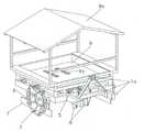
도1은 본 발명의 사시도이며, 도2는 탑승실(9)과 햇빛가리개(9a)가 분리된 요부사시도이며, 도3은 본 발명의 작동개념도를 도시한 것이며, 도4는 트랙터에 견인되어 사용되는 실시예를 도시한 것이다.1 is a perspective view of the present invention, Figure 2 is a perspective view of the
본 발명인 파종기 몸체(1)의 선단부에는 경운기나 트랙터에 부착될 수 있도록 견인구(1a)가 형성되고, 이에 견인시 파종기 몸체(1)의 좌우측에 설치된 바퀴(2)가 회전된다. 이의 축(4)에 스프로킷(3)이 설치되어 체인(3a)에 의해 스프로킷(3)이 부착된 구동축(4a)이 회전하여 다수개의 버킷(5)이 설치된 이송체인(5a)을 회전하게 된다. 이의 장치 상부에는 작업자가 탑승하여 버킷(5)에 씨감자를 담을 수 있도록 탑승실(9)이 설치되고, 햇빛과 비를 막을 수 있는 햇빛가리개(9a)가 형성된다. 경운기나 트랙터에 견인되는 파종기 몸체(1)의 바퀴(2)는 회전하게 되고, 이 회전력으로 다수개의 버킷(5)이 점차적으로 전진하고, 견일력으로 밭이랑(10)을 굴착하여 고랑(10a)을 형성하는 굴착관(6)에 형성된 안내관(6a)을 통해 씨감자(11)를 낙하시킨다. 낙하된 씨감자(11)는 굴착된 고랑(10a)에 파종되고 파종기 몸체(1)가 진행하므로 굴착관(6)의 후측에 형성된 트임구(6b)를 통해 빠져나오게 된다. 또 한 상기의 굴착관(6)이 굴착하는 과정에서 밭이랑(10)이 붕괴되지 않도록 흙가이드판(7)이 형성되어 밭이랑(10)의 양측을 감싸게 되고, 파종기 몸체(1)의 후미에 형성된 흙덮개판(8)에 의해 씨감자(11)가 밭이랑(10)의 고랑(10a)속에 복토되는 일련의 과정이 반복된다. 상기의 굴착관(6)은 높이조절부(6c)를 통해 굴착깊이를 조절할 수 있으며, 또한 체인(3a)을 구동하는 스프로킷(3)의 크기를 변경하여 파종간격을 조절할 수도 있다.At the distal end of the planter body (1) of the present invention, a tow (1a) is formed to be attached to the tiller or tractor, the wheel (2) installed on the left and right sides of the planter body (1) is rotated. The
본 출원인이 선출원 등록된 실용신안등록 제0134514호에는 다수개의 버킷(5)이 형성된 이송체인(5a)이 수평으로 형성되었으며, 이로 인해 굴착관(6)에 형성된 안내관(6a)의 위치가 높게 형성됨으로써 투입된 씨감자(11)의 낙하거리가 높아서 파종간격이 일정치 않았다. 따라서 본 발명은 이의 문제점을 해결하고자 이송체인(5a)을 구동하는 구동축(4a)에 일정간격을 두어 이송체인(5a)이 수평을 이루어 탑승실(9)에서 투입구(9b)를 통해 씨감자(11)를 투입하기에 용이하도록 안내축(4b)을 추가 설치하고, 굴착관(6) 근처에 위치한 아이들축(4c)의 위치를 낮추어 이송체인(5a)이 삼각형의 모양으로 형성되면서 작동하도록 하고, 굴착관(6)에 형성된 안내관(6a)의 위치도 낮아진 버킷(5)의 위치에 맞게 낮추게 되어 씨감자(11)의 낙하거리를 줄임으로서 파종간격의 불규칙함을 최소화할 수 있도록 한 것이다. 또한, 밭이랑(10)에서 굴착관(6)에 의해 형성된 두 줄의 고랑(10a)이 형성되고, 이는 흙덮개판(8)에 의해 고랑(10a)속에 낙하된 씨감자(11)가 흙속에 덮인 후에도 형성된 고랑(10a)이 남아 있게 되고, 이는 어린 새싹이 돋았을 때에 밭이랑(10)을 덮는 비닐에 바로 닿지 않도록 하므로 냉해의 피해를 막을 수 있는 역할을 하게 된다.Utility Model Registration No. 0134514 to which the applicant has filed a prior application is horizontally formed with a transfer chain (5a) formed with a plurality of
도4는 트랙터에 견인되는 본 발명의 감자 파종기의 실시예로서 트랙터 조종사 1명과 탑승실(9)에서 씨감자(11)를 버킷(5)에 투입하는 인원 2명으로 실제 작업한 경우, 8시간 작업에 2000㎡을 작업할 수 있다. 이에 비해 수작업시는 13명의 인원으로 320㎡밖에 작업할 수 없다. 따라서, 생산성에 있어 매우 유용한 발명인 것이다.Figure 4 is an embodiment of the potato planter of the present invention towed to the tractor when the tractor pilot and the actual work with two people to put the
도1은 본 발명의 사시도1 is a perspective view of the present invention
도2는 도1의 요부사시도2 is a perspective view of FIG. 1
도3은 본 발명의 작동개략도Figure 3 is a schematic operation diagram of the present invention
도4는 본 발명의 실시예도Figure 4 is an embodiment of the present invention
※도면의 주요부분에 대한 부호의 설명※ Explanation of symbols for main parts of drawing
1-파종기 몸체1a-견인구2-바퀴1-
3-스프로킷3a-체인4-축3-
4a-구동축4b-안내축4c-아이들축4a-
5-버킷5a-이송체인6-굴착관5-
6a-안내관6b-트임구6c-높이조절부6a-
7-흙가이드판8-흙덮개판9-탑승실7-soil guide board 8-soil board 9-boarding room
9a-햇빛가리개9b-투입구10-밭이랑9a-sunshade 9b-entry 10-field
10a-고랑11-씨감자10a-furrow 11-seed potato
Claims (1)
Translated fromKoreanPriority Applications (1)
| Application Number | Priority Date | Filing Date | Title |
|---|---|---|---|
| KR1020070087545AKR20070093944A (en) | 2007-08-30 | 2007-08-30 | Potato planters |
Applications Claiming Priority (1)
| Application Number | Priority Date | Filing Date | Title |
|---|---|---|---|
| KR1020070087545AKR20070093944A (en) | 2007-08-30 | 2007-08-30 | Potato planters |
Publications (1)
| Publication Number | Publication Date |
|---|---|
| KR20070093944Atrue KR20070093944A (en) | 2007-09-19 |
Family
ID=38687962
Family Applications (1)
| Application Number | Title | Priority Date | Filing Date |
|---|---|---|---|
| KR1020070087545ACeasedKR20070093944A (en) | 2007-08-30 | 2007-08-30 | Potato planters |
Country Status (1)
| Country | Link |
|---|---|
| KR (1) | KR20070093944A (en) |
Cited By (8)
| Publication number | Priority date | Publication date | Assignee | Title |
|---|---|---|---|---|
| KR101136405B1 (en)* | 2009-05-21 | 2012-04-18 | 박덕천 | a garlic seeder |
| KR101365556B1 (en)* | 2012-03-16 | 2014-02-26 | 박덕천 | a garlic seeder |
| CN107548639A (en)* | 2017-09-25 | 2018-01-09 | 青岛农业大学 | Garlic planter and its type of seeding |
| KR20190036674A (en) | 2017-09-28 | 2019-04-05 | 대한민국(농촌진흥청장) | A Potato planter equipped with bottle neck reducing device and potato cutting device |
| KR20190135638A (en) | 2018-05-29 | 2019-12-09 | 김재동 | A Semi-auto type potato planter |
| KR102055094B1 (en) | 2019-05-16 | 2019-12-12 | 조진석 | Seeding apparatus having a-type bucket conveyor type metering apparatus |
| CN111972092A (en)* | 2020-09-27 | 2020-11-24 | 吉林省康达农业机械有限公司 | Novel potato seeding device |
| CN113692819A (en)* | 2020-05-21 | 2021-11-26 | 绿色马克斯股份公司 | High-efficiency monitoring potato planter |
- 2007
- 2007-08-30KRKR1020070087545Apatent/KR20070093944A/ennot_activeCeased
Cited By (10)
| Publication number | Priority date | Publication date | Assignee | Title |
|---|---|---|---|---|
| KR101136405B1 (en)* | 2009-05-21 | 2012-04-18 | 박덕천 | a garlic seeder |
| KR101365556B1 (en)* | 2012-03-16 | 2014-02-26 | 박덕천 | a garlic seeder |
| CN107548639A (en)* | 2017-09-25 | 2018-01-09 | 青岛农业大学 | Garlic planter and its type of seeding |
| CN107548639B (en)* | 2017-09-25 | 2022-12-16 | 青岛农业大学 | Garlic seeder and its sowing method |
| KR20190036674A (en) | 2017-09-28 | 2019-04-05 | 대한민국(농촌진흥청장) | A Potato planter equipped with bottle neck reducing device and potato cutting device |
| KR20190135638A (en) | 2018-05-29 | 2019-12-09 | 김재동 | A Semi-auto type potato planter |
| KR102055094B1 (en) | 2019-05-16 | 2019-12-12 | 조진석 | Seeding apparatus having a-type bucket conveyor type metering apparatus |
| CN113692819A (en)* | 2020-05-21 | 2021-11-26 | 绿色马克斯股份公司 | High-efficiency monitoring potato planter |
| KR20210144051A (en)* | 2020-05-21 | 2021-11-30 | 주식회사 그린맥스 | High Efficiency Monitoring Potato Seeder |
| CN111972092A (en)* | 2020-09-27 | 2020-11-24 | 吉林省康达农业机械有限公司 | Novel potato seeding device |
Similar Documents
| Publication | Publication Date | Title |
|---|---|---|
| KR101963194B1 (en) | Line seeding type garlic planter | |
| JP5577552B2 (en) | Agricultural machines that can be fertilized | |
| KR20070093944A (en) | Potato planters | |
| CN104380865B (en) | Soil bar deep ploughing fertilizer returns soil and corn seeding suppression integral machine | |
| KR102041505B1 (en) | Transmplanting device for crops | |
| CN105284245B (en) | A kind of adjustable potatoes full film double-furrow seeder | |
| CN204579077U (en) | The capable clear bar clay fertilizer of a kind of maize seed revolves mixed single two adjustable cave sower of spreading manuer in holes of strain | |
| CN103392416A (en) | Auger type earth covering equipment | |
| CN109068584B (en) | Sugarcane transplanting machine | |
| CN204272622U (en) | Soil bar deep ploughing fertilizer returns soil and suppresses integral machine with corn seeding | |
| CN102783290A (en) | Wheel type rice wide-narrow-line direct seeding fertilization combined machine | |
| CN202476073U (en) | Seeder | |
| KR20200046312A (en) | Seeding machine | |
| CN110637564B (en) | Automatic operation all-in-one is planted to big-arch shelter crops | |
| CN104782277B (en) | A kind of peanut seeding device with chain tensioning mechanism | |
| KR101727638B1 (en) | Cultivator-mounted Seeder | |
| KR101852841B1 (en) | Soil layer forming apparatus for portable onion seed sowing | |
| KR101846928B1 (en) | Garlic sower | |
| KR20180042609A (en) | Planting machine for sweet potatoes and operating method using the same | |
| JP2013046609A (en) | Method for growing crop and agricultural machine | |
| CN201011761Y (en) | Double-row peanut sowing machine | |
| CN203167554U (en) | Seeding machine | |
| CN118044376A (en) | A double-row fertilization automatic small-grain adjustable seeder | |
| CN204272621U (en) | A kind of sower being applicable to rice straw mulching agronomy pattern plantation potato | |
| JP7473999B1 (en) | Tillage and ridge-making sowing machine and tillage and ridge-making sowing method |
Legal Events
| Date | Code | Title | Description |
|---|---|---|---|
| A201 | Request for examination | ||
| PA0109 | Patent application | Patent event code:PA01091R01D Comment text:Patent Application Patent event date:20070830 | |
| PA0201 | Request for examination | ||
| PG1501 | Laying open of application | ||
| E902 | Notification of reason for refusal | ||
| PE0902 | Notice of grounds for rejection | Comment text:Notification of reason for refusal Patent event date:20081126 Patent event code:PE09021S01D | |
| E601 | Decision to refuse application | ||
| PE0601 | Decision on rejection of patent | Patent event date:20090506 Comment text:Decision to Refuse Application Patent event code:PE06012S01D Patent event date:20081126 Comment text:Notification of reason for refusal Patent event code:PE06011S01I |