KR20070087196A - In-situ chamber cleaning method to remove byproduct deposition from chemical vapor etching chamber - Google Patents
In-situ chamber cleaning method to remove byproduct deposition from chemical vapor etching chamberDownload PDFInfo
- Publication number
- KR20070087196A KR20070087196AKR1020077016827AKR20077016827AKR20070087196AKR 20070087196 AKR20070087196 AKR 20070087196AKR 1020077016827 AKR1020077016827 AKR 1020077016827AKR 20077016827 AKR20077016827 AKR 20077016827AKR 20070087196 AKR20070087196 AKR 20070087196A
- Authority
- KR
- South Korea
- Prior art keywords
- processing chamber
- chamber
- substrate
- support member
- gas
- Prior art date
- Legal status (The legal status is an assumption and is not a legal conclusion. Google has not performed a legal analysis and makes no representation as to the accuracy of the status listed.)
- Ceased
Links
Images


Classifications
- C—CHEMISTRY; METALLURGY
- C23—COATING METALLIC MATERIAL; COATING MATERIAL WITH METALLIC MATERIAL; CHEMICAL SURFACE TREATMENT; DIFFUSION TREATMENT OF METALLIC MATERIAL; COATING BY VACUUM EVAPORATION, BY SPUTTERING, BY ION IMPLANTATION OR BY CHEMICAL VAPOUR DEPOSITION, IN GENERAL; INHIBITING CORROSION OF METALLIC MATERIAL OR INCRUSTATION IN GENERAL
- C23C—COATING METALLIC MATERIAL; COATING MATERIAL WITH METALLIC MATERIAL; SURFACE TREATMENT OF METALLIC MATERIAL BY DIFFUSION INTO THE SURFACE, BY CHEMICAL CONVERSION OR SUBSTITUTION; COATING BY VACUUM EVAPORATION, BY SPUTTERING, BY ION IMPLANTATION OR BY CHEMICAL VAPOUR DEPOSITION, IN GENERAL
- C23C16/00—Chemical coating by decomposition of gaseous compounds, without leaving reaction products of surface material in the coating, i.e. chemical vapour deposition [CVD] processes
- C23C16/44—Chemical coating by decomposition of gaseous compounds, without leaving reaction products of surface material in the coating, i.e. chemical vapour deposition [CVD] processes characterised by the method of coating
- C23C16/50—Chemical coating by decomposition of gaseous compounds, without leaving reaction products of surface material in the coating, i.e. chemical vapour deposition [CVD] processes characterised by the method of coating using electric discharges
- B—PERFORMING OPERATIONS; TRANSPORTING
- B08—CLEANING
- B08B—CLEANING IN GENERAL; PREVENTION OF FOULING IN GENERAL
- B08B7/00—Cleaning by methods not provided for in a single other subclass or a single group in this subclass
- B—PERFORMING OPERATIONS; TRANSPORTING
- B08—CLEANING
- B08B—CLEANING IN GENERAL; PREVENTION OF FOULING IN GENERAL
- B08B7/00—Cleaning by methods not provided for in a single other subclass or a single group in this subclass
- B08B7/0035—Cleaning by methods not provided for in a single other subclass or a single group in this subclass by radiant energy, e.g. UV, laser, light beam or the like
- C—CHEMISTRY; METALLURGY
- C23—COATING METALLIC MATERIAL; COATING MATERIAL WITH METALLIC MATERIAL; CHEMICAL SURFACE TREATMENT; DIFFUSION TREATMENT OF METALLIC MATERIAL; COATING BY VACUUM EVAPORATION, BY SPUTTERING, BY ION IMPLANTATION OR BY CHEMICAL VAPOUR DEPOSITION, IN GENERAL; INHIBITING CORROSION OF METALLIC MATERIAL OR INCRUSTATION IN GENERAL
- C23C—COATING METALLIC MATERIAL; COATING MATERIAL WITH METALLIC MATERIAL; SURFACE TREATMENT OF METALLIC MATERIAL BY DIFFUSION INTO THE SURFACE, BY CHEMICAL CONVERSION OR SUBSTITUTION; COATING BY VACUUM EVAPORATION, BY SPUTTERING, BY ION IMPLANTATION OR BY CHEMICAL VAPOUR DEPOSITION, IN GENERAL
- C23C16/00—Chemical coating by decomposition of gaseous compounds, without leaving reaction products of surface material in the coating, i.e. chemical vapour deposition [CVD] processes
- C23C16/44—Chemical coating by decomposition of gaseous compounds, without leaving reaction products of surface material in the coating, i.e. chemical vapour deposition [CVD] processes characterised by the method of coating
- C23C16/50—Chemical coating by decomposition of gaseous compounds, without leaving reaction products of surface material in the coating, i.e. chemical vapour deposition [CVD] processes characterised by the method of coating using electric discharges
- C23C16/503—Chemical coating by decomposition of gaseous compounds, without leaving reaction products of surface material in the coating, i.e. chemical vapour deposition [CVD] processes characterised by the method of coating using electric discharges using DC or AC discharges
- C—CHEMISTRY; METALLURGY
- C23—COATING METALLIC MATERIAL; COATING MATERIAL WITH METALLIC MATERIAL; CHEMICAL SURFACE TREATMENT; DIFFUSION TREATMENT OF METALLIC MATERIAL; COATING BY VACUUM EVAPORATION, BY SPUTTERING, BY ION IMPLANTATION OR BY CHEMICAL VAPOUR DEPOSITION, IN GENERAL; INHIBITING CORROSION OF METALLIC MATERIAL OR INCRUSTATION IN GENERAL
- C23C—COATING METALLIC MATERIAL; COATING MATERIAL WITH METALLIC MATERIAL; SURFACE TREATMENT OF METALLIC MATERIAL BY DIFFUSION INTO THE SURFACE, BY CHEMICAL CONVERSION OR SUBSTITUTION; COATING BY VACUUM EVAPORATION, BY SPUTTERING, BY ION IMPLANTATION OR BY CHEMICAL VAPOUR DEPOSITION, IN GENERAL
- C23C16/00—Chemical coating by decomposition of gaseous compounds, without leaving reaction products of surface material in the coating, i.e. chemical vapour deposition [CVD] processes
- C23C16/44—Chemical coating by decomposition of gaseous compounds, without leaving reaction products of surface material in the coating, i.e. chemical vapour deposition [CVD] processes characterised by the method of coating
- C23C16/50—Chemical coating by decomposition of gaseous compounds, without leaving reaction products of surface material in the coating, i.e. chemical vapour deposition [CVD] processes characterised by the method of coating using electric discharges
- C23C16/505—Chemical coating by decomposition of gaseous compounds, without leaving reaction products of surface material in the coating, i.e. chemical vapour deposition [CVD] processes characterised by the method of coating using electric discharges using radio frequency discharges
- C—CHEMISTRY; METALLURGY
- C23—COATING METALLIC MATERIAL; COATING MATERIAL WITH METALLIC MATERIAL; CHEMICAL SURFACE TREATMENT; DIFFUSION TREATMENT OF METALLIC MATERIAL; COATING BY VACUUM EVAPORATION, BY SPUTTERING, BY ION IMPLANTATION OR BY CHEMICAL VAPOUR DEPOSITION, IN GENERAL; INHIBITING CORROSION OF METALLIC MATERIAL OR INCRUSTATION IN GENERAL
- C23C—COATING METALLIC MATERIAL; COATING MATERIAL WITH METALLIC MATERIAL; SURFACE TREATMENT OF METALLIC MATERIAL BY DIFFUSION INTO THE SURFACE, BY CHEMICAL CONVERSION OR SUBSTITUTION; COATING BY VACUUM EVAPORATION, BY SPUTTERING, BY ION IMPLANTATION OR BY CHEMICAL VAPOUR DEPOSITION, IN GENERAL
- C23C16/00—Chemical coating by decomposition of gaseous compounds, without leaving reaction products of surface material in the coating, i.e. chemical vapour deposition [CVD] processes
- C23C16/44—Chemical coating by decomposition of gaseous compounds, without leaving reaction products of surface material in the coating, i.e. chemical vapour deposition [CVD] processes characterised by the method of coating
- C23C16/50—Chemical coating by decomposition of gaseous compounds, without leaving reaction products of surface material in the coating, i.e. chemical vapour deposition [CVD] processes characterised by the method of coating using electric discharges
- C23C16/511—Chemical coating by decomposition of gaseous compounds, without leaving reaction products of surface material in the coating, i.e. chemical vapour deposition [CVD] processes characterised by the method of coating using electric discharges using microwave discharges
- H—ELECTRICITY
- H01—ELECTRIC ELEMENTS
- H01J—ELECTRIC DISCHARGE TUBES OR DISCHARGE LAMPS
- H01J37/00—Discharge tubes with provision for introducing objects or material to be exposed to the discharge, e.g. for the purpose of examination or processing thereof
- H01J37/32—Gas-filled discharge tubes
- H01J37/32009—Arrangements for generation of plasma specially adapted for examination or treatment of objects, e.g. plasma sources
- H01J37/32357—Generation remote from the workpiece, e.g. down-stream
- H—ELECTRICITY
- H01—ELECTRIC ELEMENTS
- H01J—ELECTRIC DISCHARGE TUBES OR DISCHARGE LAMPS
- H01J37/00—Discharge tubes with provision for introducing objects or material to be exposed to the discharge, e.g. for the purpose of examination or processing thereof
- H01J37/32—Gas-filled discharge tubes
- H01J37/32431—Constructional details of the reactor
- H01J37/3244—Gas supply means
- H—ELECTRICITY
- H01—ELECTRIC ELEMENTS
- H01J—ELECTRIC DISCHARGE TUBES OR DISCHARGE LAMPS
- H01J37/00—Discharge tubes with provision for introducing objects or material to be exposed to the discharge, e.g. for the purpose of examination or processing thereof
- H01J37/32—Gas-filled discharge tubes
- H01J37/32431—Constructional details of the reactor
- H01J37/32458—Vessel
- H01J37/32522—Temperature
- H—ELECTRICITY
- H01—ELECTRIC ELEMENTS
- H01J—ELECTRIC DISCHARGE TUBES OR DISCHARGE LAMPS
- H01J37/00—Discharge tubes with provision for introducing objects or material to be exposed to the discharge, e.g. for the purpose of examination or processing thereof
- H01J37/32—Gas-filled discharge tubes
- H01J37/32431—Constructional details of the reactor
- H01J37/32798—Further details of plasma apparatus not provided for in groups H01J37/3244 - H01J37/32788; special provisions for cleaning or maintenance of the apparatus
- H01J37/32853—Hygiene
- H01J37/32862—In situ cleaning of vessels and/or internal parts
- H—ELECTRICITY
- H01—ELECTRIC ELEMENTS
- H01L—SEMICONDUCTOR DEVICES NOT COVERED BY CLASS H10
- H01L21/00—Processes or apparatus adapted for the manufacture or treatment of semiconductor or solid state devices or of parts thereof
- H01L21/02—Manufacture or treatment of semiconductor devices or of parts thereof
- H01L21/02104—Forming layers
- H01L21/02365—Forming inorganic semiconducting materials on a substrate
- H01L21/02612—Formation types
- H01L21/02617—Deposition types
- H01L21/0262—Reduction or decomposition of gaseous compounds, e.g. CVD
- H—ELECTRICITY
- H01—ELECTRIC ELEMENTS
- H01L—SEMICONDUCTOR DEVICES NOT COVERED BY CLASS H10
- H01L21/00—Processes or apparatus adapted for the manufacture or treatment of semiconductor or solid state devices or of parts thereof
- H01L21/67—Apparatus specially adapted for handling semiconductor or electric solid state devices during manufacture or treatment thereof; Apparatus specially adapted for handling wafers during manufacture or treatment of semiconductor or electric solid state devices or components ; Apparatus not specifically provided for elsewhere
- H01L21/67005—Apparatus not specifically provided for elsewhere
- H01L21/67011—Apparatus for manufacture or treatment
- H01L21/67155—Apparatus for manufacturing or treating in a plurality of work-stations
- H01L21/67207—Apparatus for manufacturing or treating in a plurality of work-stations comprising a chamber adapted to a particular process
- H—ELECTRICITY
- H10—SEMICONDUCTOR DEVICES; ELECTRIC SOLID-STATE DEVICES NOT OTHERWISE PROVIDED FOR
- H10D—INORGANIC ELECTRIC SEMICONDUCTOR DEVICES
- H10D30/00—Field-effect transistors [FET]
- H10D30/01—Manufacture or treatment
- H10D30/021—Manufacture or treatment of FETs having insulated gates [IGFET]
- H10D30/0212—Manufacture or treatment of FETs having insulated gates [IGFET] using self-aligned silicidation
- H—ELECTRICITY
- H10—SEMICONDUCTOR DEVICES; ELECTRIC SOLID-STATE DEVICES NOT OTHERWISE PROVIDED FOR
- H10D—INORGANIC ELECTRIC SEMICONDUCTOR DEVICES
- H10D64/00—Electrodes of devices having potential barriers
- H10D64/01—Manufacture or treatment
- H10D64/021—Manufacture or treatment using multiple gate spacer layers, e.g. bilayered sidewall spacers
- H—ELECTRICITY
- H10—SEMICONDUCTOR DEVICES; ELECTRIC SOLID-STATE DEVICES NOT OTHERWISE PROVIDED FOR
- H10D—INORGANIC ELECTRIC SEMICONDUCTOR DEVICES
- H10D30/00—Field-effect transistors [FET]
- H10D30/01—Manufacture or treatment
- H10D30/021—Manufacture or treatment of FETs having insulated gates [IGFET]
- H10D30/0223—Manufacture or treatment of FETs having insulated gates [IGFET] having source and drain regions or source and drain extensions self-aligned to sides of the gate
- H10D30/0227—Manufacture or treatment of FETs having insulated gates [IGFET] having source and drain regions or source and drain extensions self-aligned to sides of the gate having both lightly-doped source and drain extensions and source and drain regions self-aligned to the sides of the gate, e.g. lightly-doped drain [LDD] MOSFET or double-diffused drain [DDD] MOSFET
- H—ELECTRICITY
- H10—SEMICONDUCTOR DEVICES; ELECTRIC SOLID-STATE DEVICES NOT OTHERWISE PROVIDED FOR
- H10D—INORGANIC ELECTRIC SEMICONDUCTOR DEVICES
- H10D30/00—Field-effect transistors [FET]
- H10D30/60—Insulated-gate field-effect transistors [IGFET]
- H10D30/601—Insulated-gate field-effect transistors [IGFET] having lightly-doped drain or source extensions, e.g. LDD IGFETs or DDD IGFETs
Landscapes
- Chemical & Material Sciences (AREA)
- Engineering & Computer Science (AREA)
- Physics & Mathematics (AREA)
- Plasma & Fusion (AREA)
- Analytical Chemistry (AREA)
- General Chemical & Material Sciences (AREA)
- Chemical Kinetics & Catalysis (AREA)
- Materials Engineering (AREA)
- Mechanical Engineering (AREA)
- Metallurgy (AREA)
- Organic Chemistry (AREA)
- Condensed Matter Physics & Semiconductors (AREA)
- Manufacturing & Machinery (AREA)
- Computer Hardware Design (AREA)
- Microelectronics & Electronic Packaging (AREA)
- Power Engineering (AREA)
- General Physics & Mathematics (AREA)
- Optics & Photonics (AREA)
- Health & Medical Sciences (AREA)
- Epidemiology (AREA)
- Public Health (AREA)
- Drying Of Semiconductors (AREA)
Abstract
Translated fromKoreanDescription
Translated fromKorean본 발명의 실시예들은 일반적으로 반도체 프로세싱 장비에 관한 것이다. 보다 구체적으로, 본 발명의 실시예들은 반도체 제조용 화학기상증착(CVD) 시스템 및 CVD 시스템의 인-시튜 건식 세정에 관한 것이다.Embodiments of the present invention generally relate to semiconductor processing equipment. More specifically, embodiments of the present invention relate to chemical vapor deposition (CVD) systems for semiconductor manufacturing and in-situ dry cleaning of CVD systems.
자연 산화물(native oxide)은 일반적으로 기판이 산소에 노출될 때 형성된다. 자연 산화물은 에칭중에 기판면이 오염될 경우 형성될 수도 있다. 자연 실리콘 산화막은, 특히 MOSFET(Metal Oxide Silicon Field Effect Transistor) 구조의 프로세싱 중에, 노출되어 있는 실리콘 함유층에 형성된다. 실리콘 산화막은 전기적으로 절연되며 접촉 전극 또는 상호연결(interconnecting) 전기 경로와의 계면에서 바람직하지 않은데 이는 막들이 큰 전기 접촉 저항을 발생시키기 때문이다. MOSFET 구조에서 전극들과 상호연결 경로들은 내열성 금속을 베어 실리콘(bare silicon)상에 증착하고 이 층을 금속 실리사이드 층을 생성하기 위해 어닐링함으로써 형성된다. 기판과 금속 사이의 계면에 있는 자연 실리콘 산화막은 금속 실리사이드를 형성하는 확산 화학 반응을 방해함으로써 실리사이드 층의 조성 균일도를 감소시킨다. 이는 전기 접촉부에서의 과열로 인한 증가된 고장률과 보다 낮은 기판 수율에 이르게 된다. 자연 실리콘 산화막은 기판상에 후속 증착되는 다른 CVD 또는 스퍼터링된 층들의 부착을 방해할 수도 있다.Native oxides are generally formed when the substrate is exposed to oxygen. Natural oxides may be formed when the substrate surface is contaminated during etching. The natural silicon oxide film is formed in the exposed silicon-containing layer, especially during processing of the metal oxide silicon field effect transistor (MOSFET) structure. Silicon oxide films are electrically insulated and are undesirable at interfaces with contact electrodes or interconnecting electrical paths because the films produce large electrical contact resistance. Electrodes and interconnecting paths in a MOSFET structure are formed by depositing a heat resistant metal on bare silicon and annealing this layer to produce a metal silicide layer. The natural silicon oxide film at the interface between the substrate and the metal interferes with the diffusion chemical reaction that forms the metal silicide, thereby reducing the compositional uniformity of the silicide layer. This leads to increased failure rates and lower substrate yields due to overheating in the electrical contacts. The native silicon oxide film may interfere with the attachment of other CVD or sputtered layers subsequently deposited on the substrate.
플루오르화수소(HF)산 및 초순수(deionize water)를 이용한 스퍼터 에칭, 건식 에칭, 및 습식 에칭 프로세스는, 대형 피처(feature) 또는 약 4:1 미만의 종횡비를 갖는 소형 피처에서 오염을 감소시켜 보려고 시도해봤다. 그러나, 자연 산화막의 제거는 효과가 없고 이들 방법들 모두의 경우 원치 않는 찌꺼기를 도입한다. 유사하게, 습식 에칭 용액은, 상기 크기의 피처에 침투하는 것에 성공한다면, 일단 에칭이 완결된 피처로부터 제거하기가 더욱 어렵다.Sputter etching, dry etching, and wet etching processes using hydrogen fluoride (HF) acid and deionize water attempt to reduce contamination in large features or small features having an aspect ratio of less than about 4: 1. I saw. However, removal of the native oxide film is ineffective and, in both of these methods, introduces unwanted debris. Similarly, a wet etch solution is more difficult to remove from a feature once the etch is complete, once it succeeds in penetrating the feature of this size.
자연 산화막을 제거하는 보다 최근의 접근법은 기판상에 불소/실리콘 함유 염을 형성하는 것이며 이는 이후 열 어닐링에 의해 제거된다. 이 접근법에서, 염의 박층은 불소 함유 가스를 실리콘 산화막 표면과 반응시킴으로써 형성된다. 염은 그 후 염을 휘발성 부산물로 해리시키기에 충분한 상승된 온도로 가열되며, 상기 부산물은 그 후 프로세싱 챔버로부터 제거된다. 반응성 불소 함유 가스의 형성은 통상적으로 열부가 또는 플라즈마 에너지에 의해 보조된다. 염은 통상적으로 기판 표면의 냉각을 요하는 감소된 온도에서 형성된다. 일련의 이러한 냉각 이후의 가열은 통상적으로 기판이 냉각되는 냉각 챔버로부터 기판이 가열되는 별개의 어닐링 챔버 또는 노(furnace)로 기판을 이송함으로써 이루어진다.A more recent approach to removing native oxide films is to form fluorine / silicon containing salts on the substrate, which are then removed by thermal annealing. In this approach, a thin layer of salt is formed by reacting a fluorine containing gas with the silicon oxide film surface. The salt is then heated to an elevated temperature sufficient to dissociate the salt into volatile byproducts, which are then removed from the processing chamber. The formation of reactive fluorine containing gas is typically assisted by heat addition or plasma energy. Salts are typically formed at reduced temperatures requiring cooling of the substrate surface. Heating after a series of such cooling is typically accomplished by transferring the substrate from the cooling chamber in which the substrate is cooled to a separate annealing chamber or furnace in which the substrate is heated.
여러 이유로, 이러한 반응성 불소 프로세싱 시퀀스는 바람직하지 않다. 즉, 웨이퍼를 전송하는 데 관련된 시간으로 인해 웨이퍼 처리량이 현저하게 감소된다. 또한, 웨이퍼는 이송 동안의 추가적인 산화 또는 다른 오염에 영향받기 쉽다. 게다가, 소유자의 비용이 두 배가 되는데 이는 두 개의 개별 챔버가 산화막 제거 프로세스를 완결하기 위해 필요하기 때문이다. 여기서 하나의 챔버에서 원격 플라즈마 발생, 가열, 냉각, 및 한 번의 건식 에칭 프로세스의 수행을 할 수 있는(즉, 인-시튜) 프로세싱 챔버에 대한 필요성이 대두된다.For various reasons, such reactive fluorine processing sequences are undesirable. That is, the wafer throughput is significantly reduced due to the time involved in transferring the wafer. In addition, the wafer is susceptible to additional oxidation or other contamination during transfer. In addition, the cost of the owner is doubled because two separate chambers are needed to complete the oxide removal process. There is a need here for a processing chamber capable of remote plasma generation, heating, cooling, and performing a single dry etch process in one chamber (ie, in-situ).
챔버의 가스 분배 플레이트가 약 180℃로 가열되고 프로세스 가스가 챔버의 프로세싱 영역으로 도입될 때, 웨이퍼 지지대는 약 35℃로 냉각되며 프로세스 화학물질은 상기 지지대의 표면을 따라 증착물을 형성한다. 이러한 증착물을 제거하기 위해 챔버를 세정하는 것은 전통적으로 챔버를 개방하고 챔버를 수동으로 세정하기 위해 시간과 노력이 필요한 습식 세정 방법에 의존해 왔다. 대안으로, 페더스털(pedestal)을 냉각하는 데 통상적으로 사용되는 유체를 가열하기 위한 시도가 이루어져 왔으나, 이러한 가열 방법은 챔버 표면을 가열하고 챔버를 세정하는 데 2 내지 3일이 소요된다. 프로세싱 챔버로부터 증착물과 찌꺼기를 제거하는 것은 비용 효율적이며 적은 프로세싱 시간을 요할 것이 요구된다.When the gas distribution plate of the chamber is heated to about 180 ° C. and the process gas is introduced into the processing region of the chamber, the wafer support is cooled to about 35 ° C. and the process chemicals form deposits along the surface of the support. Cleaning the chamber to remove such deposits has traditionally relied on wet cleaning methods that require time and effort to open the chamber and manually clean the chamber. Alternatively, attempts have been made to heat fluids commonly used to cool pedestals, but this heating method takes two to three days to heat the chamber surface and clean the chamber. Removing deposits and debris from the processing chamber is cost effective and requires less processing time.
기판을 프로세싱하기 위한 프로세싱 챔버가 제공된다. 일 측면에서, 챔버는 챔버 몸체와, 챔버 몸체내에 적어도 부분적으로 배치되며 상부에 기판을 지지하는 지지 어셈블리를 포함한다. 챔버는 챔버 몸체의 상부면에 위치되는 리드(lid) 어셈블리를 더 포함한다. 리드 어셈블리는 플라즈마를 생성하기 위한 U 형상 단면을 갖는 원격 플라즈마 영역과 유체 소통한다. 원격 플라즈마 영역은 원통형 전극과 컵 모양의 그라운드에 의해 규정된다. RF 전력 소스가 원통형 전극에 연결된다.A processing chamber is provided for processing a substrate. In one aspect, the chamber includes a chamber body and a support assembly at least partially disposed within the chamber body and supporting the substrate thereon. The chamber further includes a lid assembly located on the top surface of the chamber body. The lid assembly is in fluid communication with a remote plasma region having a U-shaped cross section for generating a plasma. The remote plasma region is defined by cylindrical electrodes and cup-shaped ground. An RF power source is connected to the cylindrical electrode.
본 발명은, 프로세싱 챔버 내의 지지 부재 내의 채널로의 냉각 유체의 흐름을 저지하는 단계, 가스 분배 플레이트의 약 0.1 인치 이내에 있도록 지지 부재를 상승시키는 단계, 가스 분배 플레이트를 가열하는 단계, 및 열전도성의 가스를 가스 분배 플레이트를 통해 프로세싱 챔버로 도입하는 단계를 포함하는, 프로세싱 챔버를 세정하는 방법 및 장치를 제공한다.The present invention is directed to retarding the flow of cooling fluid into a channel in a support member in a processing chamber, raising the support member to be within about 0.1 inches of the gas distribution plate, heating the gas distribution plate, and thermally conductive gas. Providing a method through a gas distribution plate into the processing chamber.
상기 언급된 본 발명의 특징들이 상세히 이해될 수 있도록, 위에서 간략히 요약된 본 발명의 보다 구체적인 기재는 실시예들을 참조하여 이루어질 수 있고, 이 실시예들의 일부는 첨부된 도면들에 도시된다. 그러나, 첨부된 도면은 본 발명의 특정 실시예들을 도시하며 따라서, 발명의 범위를 제한하는 것으로 생각되지 않아야함에 주의하여야 하는데, 이는 본 발명이 다른 균등하게 유효한 실시예들을 수용할 수 있기 때문이다.BRIEF DESCRIPTION OF THE DRAWINGS In order that the above-mentioned features of the present invention may be understood in detail, a more specific description of the invention briefly summarized above may be made with reference to embodiments, some of which are illustrated in the accompanying drawings. It is to be noted, however, that the appended drawings illustrate specific embodiments of the invention and, therefore, should not be considered as limiting the scope of the invention, as the invention is capable of accommodating other equally effective embodiments.
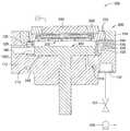
도 1A는 가열, 냉각 및 에칭을 위한 예시적인 프로세싱 챔버(100)의 부분단면도이다.1A is a partial cross-sectional view of an
도 1B는 도 1A의 프로세싱 챔버내에 배치된 예시적인 라이너의 확대도이다.1B is an enlarged view of an exemplary liner disposed within the processing chamber of FIG. 1A.
도 2A는 도 1A에 도시된 챔버 몸체의 상단부에 배치될 수 있는 예시적인 리드 어셈블리의 확대단면도이다.FIG. 2A is an enlarged cross-sectional view of an exemplary lead assembly that may be disposed on the upper end of the chamber body shown in FIG. 1A.
도 2B 및 2C는 도 2A의 가스 분배 플레이트의 확대도이다.2B and 2C are enlarged views of the gas distribution plate of FIG. 2A.
도 3A는 도 1A의 챔버 몸체(112)내에 적어도 부분적으로 배치되는 예시적인 지지 어셈블리의 부분 단면도이다.3A is a partial cross-sectional view of an exemplary support assembly disposed at least partially within the
도 3B는 도 3A의 예시적인 지지 부재(300)의 확대된 부분단면도이다.3B is an enlarged partial cross-sectional view of the
도 4A는 또 다른 예시적인 리드 어셈블리(400)의 단면도이다.4A is a cross-sectional view of another
도 4B는 도 4A의 상부 전극의 확대된 부분단면도이다.4B is an enlarged partial cross-sectional view of the upper electrode of FIG. 4A.
도 4C는 도 4A의 리드 어셈블리(400)를 이용하는 예시적인 프로세싱 챔버(100)의 부분단면도이다.4C is a partial cross-sectional view of an
도 5A-I는 예시적인 능동 전자 소자, 가령 MOSFET 구조를 형성하는 제조 시퀀스의 부분 개요도이다.5A-I are partial schematic diagrams of fabrication sequences forming exemplary active electronic devices, such as MOSFET structures.
도 6은 다중 프로세싱 동작을 수행하는 예시적인 멀티-챔버 프로세싱 시스템의 개략도이다.6 is a schematic diagram of an example multi-chamber processing system for performing multiple processing operations.
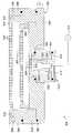
도 7은 원격 플라즈마 발생기를 갖는 프로세싱 챔버(100)의 한 가지 대안의 실시예를 보여주는 부분 단면도이다.7 is a partial cross-sectional view showing one alternative embodiment of a
도 8은 원격 플라즈마 발생기의 단면도이다.8 is a cross-sectional view of a remote plasma generator.
임의의 수의 기판 프로세싱 기법들을 위한 프로세싱 챔버를 세정하는 방법 및 장치가 제공된다. 챔버는 진공을 파괴하지 않고 기판 표면의 가열 및 냉각 모두를 요하는 플라즈마 보조 건식 에칭 프로세스를 수행하는 데 특히 유용하다. 예를 들어, 본원에 기재된 프로세싱 챔버는 기판 표면으로부터 산화물과 다른 오염물질을 제거하기 위한 전처리(FEOL, front-end-of line) 세정 챔버에 대해 가장 적합하도록 계획되었다.Methods and apparatus are provided for cleaning a processing chamber for any number of substrate processing techniques. The chamber is particularly useful for performing plasma assisted dry etching processes that require both heating and cooling of the substrate surface without breaking the vacuum. For example, the processing chambers described herein are designed to be most suitable for front-end-of-line (FEOL) cleaning chambers to remove oxides and other contaminants from the substrate surface.
본원에 사용된 "기판 표면"은 프로세싱이 그 상부에서 수행되는 임의의 기판 표면을 말한다. 예를 들어, 기판 표면은 실리콘, 실리콘 산화물, 도핑된 실리콘, 게르마늄, 갈륨비소, 유리, 사파이어와, 금속, 금속 질화물, 금속 합금, 및 다른 전도성 물질들과 같은 임의의 기타 물질들을 포함할 수 있다. 기판 표면은 또한 실리콘 산화물, 유기실리케이트, 및 탄소 도핑된 실리콘 산화물과 같은 유전 물질들을 포함할 수 있다. 기판 그 자체는 임의의 특정 크기 또는 형상으로 제한되지 않는다. 일 측면에서, 용어 "기판"은 200mm 직경 또는 300mm 직경을 갖는 원형 웨이퍼를 말한다. 다른 측면에서, 용어 "기판"은 팔각형, 정사각형, 직사각형, 곡면 또는 비원형 작업물, 가령 평판 디스플레이의 제조에 사용되는 글라스 기판을 말한다.As used herein, “substrate surface” refers to any substrate surface on which processing is performed thereon. For example, the substrate surface may include silicon, silicon oxide, doped silicon, germanium, gallium arsenide, glass, sapphire, and any other materials such as metals, metal nitrides, metal alloys, and other conductive materials. . The substrate surface may also include dielectric materials such as silicon oxide, organosilicate, and carbon doped silicon oxide. The substrate itself is not limited to any particular size or shape. In one aspect, the term “substrate” refers to a circular wafer having a 200 mm diameter or 300 mm diameter. In another aspect, the term “substrate” refers to a glass substrate used in the manufacture of octagonal, square, rectangular, curved or non-circular workpieces, such as flat panel displays.
도 1A는 프로세싱 챔버(100)를 도시하는 부분 단면도이다. 일 실시예에서, 프로세싱 챔버(100)는 챔버 몸체(112), 리드 어셈블리(200), 및 지지 어셈블리(300)를 포함한다. 리드 어셈블리(200)는 챔버 몸체(112)의 상단부에 배치되고, 지지 어셈블리(300)는 챔버 몸체(112)내에 적어도 부분적으로 배치된다. 프로세싱 챔버(100)와 관련 하드웨어는 하나 이상의 호환가능한 물질, 가령 알루미늄, 양극산화 처리된 알루미늄, 니켈 도금 알루미늄, 니켈 도금 알루미늄 6061-T6, 스테인리스 강, 및 이들의 조합 및 합금들로부터 형성되는 것이 바람직하다.1A is a partial cross-sectional view illustrating a
챔버 몸체(112)는 프로세싱 챔버(100)의 내부로의 액세스를 제공하도록 챔버 몸체의 측벽에 형성된 슬릿 밸브 개구(160)를 포함한다. 슬릿 밸브 개구(160)는 웨이퍼 처리 로봇(비도시)에 의한 챔버 몸체(112) 내부로의 액세스를 허용하도록 선택적으로 개폐된다. 웨이퍼 처리 로봇은 당업자에게 주지되어 있고, 임의의 적합한 로봇이 사용될 수 있다. 예를 들어, 예시적인 로봇 이송 어셈블리는, 1990년 8월 28일 등록된 발명의 명칭이 "Multi-chamber Integrated Process System"인 본원인에게 함께 양수된 U.S. Pat. No. 4,951,601에 기재되어 있으며, 그 전체 개시내용이 참조에 의해 본원에 포함된다. 일 실시예에서, 웨이퍼는 슬릿 밸브 개구(160)를 통하여 인접한 이송 챔버 및/또는 로드락 챔버, 또는 클러스터 툴 내부의 다른 챔버로 프로세싱 챔버(100) 내외부로 이송될 수 있다. 프로세싱 챔버(100)에 결합될 수 있는 유형의 클러스터 툴은 1993년 2월 16일 등록된 발명의 명칭이 "Staged-Vaccum Wafer Processing System and Method"인 본원인에게 함께 양수된 U.S. Pat. No. 5,186,717에 기재되어 있으며, 그 전체 개시내용이 참조에 의해 본원에 포함된다.The
하나 이상의 실시예에서, 챔버 몸체(112)는 챔버 몸체 내부에 형성되며 열 전달 유체를 유동시키기 위한 채널(113)을 포함한다. 챔버 몸체(112)의 온도는 챔버 벽에서의 가스나 부산물의 원치 않는 응축을 방지하기 위해 중요하다. 예시적인 열 전달 유체는 물, 에틸렌글리콜, 또는 이들의 혼합물을 포함한다. 예시적인 열 전달 유체는 또한 질소 가스를 포함할 수도 있다.In one or more embodiments, the
챔버 몸체(112)는 지지 어셈블리(300)를 둘러싸는 라이너(133)를 더 포함할 수 있다. 라이너(133)는 서비스 및 세정을 위해 착탈가능한 것이 바람직하다. 라이너(133)는 알루미늄과 같은 금속, 또는 세라믹 물질로 제조될 수 있다. 그러나, 라이너(133)는 임의의 프로세스 호환가능한 물질일 수 있다. 라이너(133)는 여기 에 증착되는 임의의 물질의 부착을 증진시키기 위하여 비드 블래스트(bead blast)될 수 있으며, 이에 의해 프로세싱 챔버(100)의 오염에 이르게 될 물질이 벗겨져 떨어지는 것(flaking)을 방지한다. 하나 이상의 실시예에서, 라이너(133)는 진공 시스템과 유체 소통되며 라이너 내부에 형성된 펌핑 채널(129)과 하나 이상의 구멍(135)을 포함한다. 구멍(135)은 펌핑 채널(129)로 유입되는 가스들을 위한 유동 경로를 제공하며, 프로세싱 챔버(100) 내부의 가스들을 위한 배출구를 제공한다.The
진공 시스템은 프로세싱 챔버(100)를 통한 가스들의 유동을 조절하기 위하여 진공 펌프(125)와 스로틀밸브(127)를 포함할 수 있다. 진공 펌프(125)는 챔버 몸체(112)에 배치된 진공 포트(131)와 연결되며, 따라서 라이너(133)내에 형성된 펌핑 채널(129)과 유체 소통한다. 용어 "가스"와 "가스들"은 달리 지적되지 않는 한 상호교환하여 사용될 수 있으며, 하나 이상의 전구체, 반응체, 촉매, 캐리어, 정화, 세정, 이들의 조합과, 챔버 몸체(112)로 유입되는 임의의 다른 유체를 말한다.The vacuum system may include a
라이너(133)를 상세하게 고찰하면, 도 1B는 라이너(133)의 일 실시예의 확대도를 도시한다. 이 실시예에서, 라이너(133)는 상부(133A)와 하부(133B)를 포함한다. 챔버 몸체(112)의 측벽에 배치된 슬릿 밸브 개구(160)와 정렬된 구멍(133C)이 라이너(133) 내부에 형성되어 챔버 몸체(112) 내외부로 기판들의 유입 및 유출을 가능하게 한다. 일반적으로 펌핑 채널(129)이 상부(133A) 내에 형성된다. 상부(133A)는 또한 이를 관통하여 형성된 하나 이상의 구멍(135)을 포함하여, 가스들에 대한 펌핑 채널(129)로의 통로 또는 유동 경로를 제공한다.Looking at
도 1A 및 1B를 참조하면, 구멍(135)에 의해 펌핑 채널(129)이 챔버 몸 체(112)내에 있는 프로세싱 영역(140)과 유체 소통된다. 프로세싱 영역(140)은 리드 어셈블리(200)의 하부면과 지지 어셈블리(300)의 상부면에 의해 규정되며, 라이너(133)에 의해 둘러싸여 있다. 구멍(135)은 균일한 크기이며 라이너(133) 주변에 균일하게 이격되어 있다. 그러나, 임의의 수, 위치, 크기, 또는 형상의 구멍들이 사용될 수 있으며, 이들 각각의 설계 변수들은 아래에서 보다 상세히 논의될 것처럼 기판 수용면에 대한 가스의 원하는 유동 패턴에 따라 변할 수 있다. 또한, 구멍(135)의 크기, 수, 및 위치는 프로세싱 챔버(100)로부터 배출되는 가스들의 균일한 유동을 얻도록 구성된다. 또한, 챔버(100)로부터의 가스의 빠른 배기를 용이하게 하기 위하여, 구멍 크기 및 위치가 빠른 또는 대용량의 펌핑을 제공하도록 구성될 수 있다. 예를 들어, 진공 포트(131)에 근접한 구멍(135)의 수와 크기는 진공 포트(131)로부터 멀리 떨어져 위치된 구멍(135)의 크기보다 작을 수 있다.1A and 1B, the pumping
역시 도 1A 및 1B를 참조하면, 라이너(133)의 하부(133B)는 이의 내부에 위치된 유동 경로 또는 진공 채널(129A)을 포함한다. 진공 채널(129A)은 위에서 기재된 진공 시스템과 유체 소통된다. 진공 채널(129A)은 또한 라이너(133)의 외경에 형성된 리세스 또는 포트(129B)를 통하여 펌핑 채널(129)과 유체 소통된다. 일반적으로, 두 개의 가스 포트들(129B)(하나만이 이 도면에 도시됨)이 상부(133A)와 하부(133B) 사이의 라이너(133)의 외경에 형성되어 있다. 가스 포트들(129)은 펌핑 채널(129)과 진공 채널(129A) 사이에 유동 경로를 제공한다. 각각의 포트들(129B)의 크기와 위치는 설계의 문제이며, 원하는 막의 화학양론, 형성되고 있는 소자의 기하구조, 프로세싱 챔버(100)의 부피 용량, 프로세싱 챔버에 결합된 진공 시스템의 용량에 의해 결정된다. 전형적으로, 포트들(129B)은 서로와 대향하여 즉, 라이너(133)의 외경에 대하여 180ㅀ 이격되어 정렬된다.Referring again to FIGS. 1A and 1B, the bottom 133B of the
동작시에, 프로세싱 챔버(100)로부터 배기되는 하나 이상의 가스들은 라이너(133)의 상부(133A)를 관통하여 형성된 구멍(135)을 통하여 펌핑 채널(129)로 유동된다. 가스는 그 후 펌핑 채널(129)내에서 유동되며 진공 포트(131)를 통하여 진공 채널(129A)로 유동된다. 가스는 진공 포트(131)를 통하여 진공 펌프(125)로 진공 채널(129A)를 벗어난다.In operation, one or more gases exhausted from the
리드 어셈블리(200)를 보다 상세히 고찰하면, 도 2A는 도 1A에 도시된 챔버 몸체(112)의 상단부에 배치될 수 있는 예시적인 리드 어셈블리(200)의 확대단면도를 도시한다. 도 1A 및 2A를 참조하면, 리드 어셈블리(200)는 도 1A에 도시된 것처럼, 서로의 상단에 적층된 다수의 컴포넌트들을 포함한다. 하나 이상의 실시예에서, 리드 어셈블리(200)는 리드 림(lid rim, 210), 가스 전달 어셈블리(220), 상부 플레이트(250)를 포함한다. 가스 전달 어셈블리(220)는 리드 림(210)의 상부면에 결합되며 리드 림과 최소한의 열 접촉을 이루도록 배치된다. 리드 어셈블리(200)의 컴포넌트들은 가령 잘 마감된 표면을 갖는 알루미늄 합금과 같이 높은 열전도성과 낮은 열 저항을 갖는 물질로 제조되는 것이 바람직하다. 컴포넌트들의 열 저항은 약 5×10⁻⁴㎡ K/W보다 작은 것이 바람직하다. 리드 림(210)은 리드 어셈블리(200)를 구성하는 컴포넌트들의 하중을 견디도록 설계되며, 가령 지지 어셈블리(300)와 같은 내부 챔버 컴포넌트들에 액세스를 제공하기 위하여 힌지 어셈블리 (이 도면에는 비도시)를 통하여 챔버 몸체(112)의 상부면에 결합된다.Looking at the
도 2B와 2C를 참조하면, 가스 전달 어셈블리(220)는 분배 플레이트 또는 샤워헤드(225)를 포함할 수 있다. 도 2B는 예시적인 가스 분배 플레이트(225)의 일 실시예의 확대도이며 도 2C는 부분단면도이다. 하나 이상의 실시예에서, 가스 분배 플레이트(225)는 실질적으로 디스크 모양이며 가스들의 유동을 분배시키기 위하여 다수의 구멍(225A) 또는 통로를 포함하여, 기판의 표면에 대하여 가스의 균일한 분배를 제공한다.2B and 2C, the
도 2A, 2B 및 2C를 참조하면, 가스 분배 플레이트(225)는 이의 주변에 형성된 환형 장착 플랜지(222)를 포함하며, 이는 리드 림(210) 위에 안착하는 크기이다. 따라서, 가스 분배 플레이트(225)는 리드 어셈블리(200)와 최소의 접촉을 이룬다. 탄성 o-링과 같은 o-링 형태 시일(224)이 환형 장착 플랜지(222)내부에 적어도 부분적으로 배치되어 리드 림(210)과의 유체 밀착(fluid-tight) 접촉을 보장하는 것이 바람직하다.2A, 2B and 2C, the
가스 전달 어셈블리(220)는 가스 분배 플레이트(225)에 인접하여 배치된 차단기 어셈블리(blocker assembly, 230)를 더 포함할 수 있다. 차단기 어셈블리(230)는 가스 분배 플레이트(225)의 후면에 가스의 균일한 분배를 제공한다. 차단기 어셈블리(230)는 알루미늄 합금으로 제조되며 양호한 열 접촉을 보장하기 위하여 가스 분배 플레이트(225)에 제거가능하게 결합되는 것이 바람직하다. 예를 들어, 차단기 어셈블리(230)는 볼트(221) 또는 유사한 파스너(fastener)를 이용하여 가스 분배 플레이트(225)에 결합될 수 있다. 차단기 어셈블리(230)는 도 2A에 도시된 것처럼 리드 림(210)과 열 접촉을 형성하지 않는 것이 바람직하다.The
하나 이상의 실시예에서, 차단기 어셈블리(230)는 제2 차단기 플레이트(235)에 장착된 제1 차단기 플레이트(233)를 포함한다. 제2 차단기 플레이트(235)는 자신을 관통하여 형성된 통로(259)를 포함한다. 바람직하게는 통로(259)가 제2 차단기 플레이트(235)를 관통해 중앙에 위치되어, 통로(259)가 상부 플레이트(250)의 하부면과 제2 차단기 플레이트(235)의 상부면에 의해 규정된 제1 공동 또는 부피(261)와 유체 소통하는 것이 바람직하다. 통로(259)는 또한 제2 차단기 플레이트(235)의 하부면과 제1 차단기 플레이트(233)의 상부면에 의해 규정된 제2 공동 또는 부피(262)와 유체 소통한다. 통로(259)는 또한 제1 차단기 플레이트(233)의 하부면과 가스 분배 플레이트(225)의 상부면에 의해 규정된 제3 공동 또는 부피(263)와 유체 소통한다. 통로(259)는 가스 유입구(223)에 결합된다. 가스 유입구(223)는 그 제1 단부에서 상부 플레이트(250)에 결합된다. 비록 도시되지는 않지만, 가스 유입구(223)는 그 제2 단부에서 하나 이상의 업스트립(upstream) 가스 소스 및/또는 다른 가스 분배 컴포넌트, 가령 가스 혼합기에 결합된다.In one or more embodiments, the
제1 차단기 플레이트(233)는 그 내부에 형성된 다수의 통로들(233A)을 포함하며, 이 통로들(233A)은 통로(259)로부터 가스 분배 플레이트(225)로 유동하는 가스들을 분산시키도록 구성된다. 비록 통로들(233A)이 원형이거나 둥근 것으로 도시되어 있지만, 통로들(233A)은 정사각형, 직사각형, 또는 임의의 다른 형상일 수 있다. 통로들(233A)은 기판의 표면에 대하여 제어되고 균일한 유량 분배를 제공하기 위하여 차단기 플레이트(233)에 대하여 크기와 위치가 정해질 수 있다. 전술한 것처럼, 제1 차단기 플레이트(233)는 이들 컴포넌트들의 세정 또는 제거를 용이하게 하기 위하여 제2 차단기 플레이트(235) 및 가스 분배 플레이트(225)로부터 용이하게 제거될 수 있다.The
사용시에, 하나 이상의 프로세스 가스들이 가스 유입구(223)를 통하여 가스 전달 어셈블리(220)로 유입된다. 프로세스 가스는 제1 부피(261)로 유동되며, 제2 차단기 플레이트(235)의 통로(259)를 통하여 제2 부피(262)로 유동된다. 프로세스 가스는 그 후 제1 차단기 플레이트(233)의 홀들(holes, 233A)을 통하여 제3 부피(263)로 분배되며, 가스가 챔버 몸체(112)내에 배치된 기판의 노출된 표면들과 만날 때까지 가스 분배 플레이트(225)의 홀들(225A)을 통해 추가로 분배된다.In use, one or more process gases enter the
가스 공급판(비도시)이 프로세싱 챔버(100)에 하나 이상의 가스들을 제공하기 위해 일반적으로 사용된다. 사용되는 특정 가스 또는 가스들은 챔버(100)내에서 수행될 프로세스 또는 프로세스들에 따른다. 예시적인 가스들은 하나 이상의 전구체, 환원제, 촉매, 캐리어, 정화, 세정, 또는 이들의 임의의 혼합물 또는 조합을 포함하나, 이에 제한되지는 않는다. 일반적으로, 프로세싱 챔버(100)로 도입된 상기 하나 이상의 가스들은 유입구(223)를 통해 리드 어셈블리(200)로 흐르며 그 후 가스 전달 어셈블리(220)를 통해 챔버 몸체(112)로 흐른다. 전기적으로 동작되는 밸브 및/또는 유동 제어 메커니즘(비도시)이 사용되어 가스 공급부로부터 프로세싱 챔버(100)로의 가스의 흐름을 제어할 수 있다. 프로세스에 따라서, 임의의 수의 가스들이 프로세싱 챔버(100)로 전달될 수 있고, 프로세싱 챔버(100) 내에서나 가스들이 프로세싱 챔버(100)로 전달되기 전에 가령 가스 혼합부(비도시)에서 혼합될 수 있다.Gas supply plates (not shown) are generally used to provide one or more gases to the
계속 도 1A 및 2A를 참조하면, 리드 어셈블리(200)는 리드 어셈블리(200)내에 반응종의 플라즈마를 생성하기 위해 전극(240)을 더 포함할 수 있다. 일 실시예에서, 전극(240)은 상부 플레이트(250)상에 지지되며 이로부터 전기적으로 절연된다. 예를 들어, 도 2A에 도시된 것처럼 상부 플레이트(250)로부터 전극(240)을 분리하는 절연 필터 링(241)이 전극(240)의 하부 주변에 배치될 수 있다. 환형 절연체(242)가 또한 절연 필터 링(241)의 외부면에 대해 배치될 수도 있다. 환형 절연체(243)는 그 후 전극(240)의 상부 주변에 배치될 수 있어서 전극(240)이 상부 플레이트(250)와 리드 어셈블리(200)의 모든 다른 요소들로부터 전기적으로 절연된다. 이러한 링들(241, 242, 243) 각각은 알루미늄 산화물이나 임의의 다른 절연체, 프로세스 호환가능한 물질로 제조될 수 있다.With continued reference to FIGS. 1A and 2A, the
하나 이상의 실시예에서, 전극(240)은 전력 소스(미도시)에 연결되며 가스 전달 어셈블리(220)는 그라운드에 연결된다(즉, 가스 전달 어셈블리(220)는 전극으로 기능함). 따라서, 하나 이상의 프로세스 가스들의 플라즈마는 전극(240)("제1 전극")과 가스 전달 어셈블리(220)("제2 전극") 사이에 있는 부피(261, 262 및/또는 263)에서 생성될 수 있다. 예를 들어, 플라즈마는 전극(240)과 차단기 어셈블리(230) 사이에서 타격(striking) 및 함유될 수 있다. 대안으로, 플라즈마는 차단기 어셈블리(230)가 없을 때는, 전극(240)과 가스 분배 플레이트(225) 사이에서 타격 및 함유될 수 있다. 또 다른 실시예에서, 플라즈마는 리드 어셈블리(200)내에 양호하게 한정되고 함유될 수 있다. 따라서 어떠한 활성 플라즈마도 챔버 몸 체(112)내에 배치된 기판과 직접 접촉하고 있지 않기 때문에 플라즈마는 "원격 플라즈마"이다. 결과적으로, 플라즈마가 기판 표면으로부터 충분히 이격되어 있으므로 기판에 대한 플라즈마 손상이 회피된다.In one or more embodiments,
가스들을 반응종으로 활성화할 수 있고 반응종들의 플라즈마를 유지할 수 있는 임의의 전력 소스가 사용될 수 있다. 예를 들어, 전력 방전 기법에 기초하여 무선 주파수(RF), 직류(DC), 또는 마이크로파(MW)가 사용될 수 있다. 활성화는 열 기반 기법, 가스 방전(breakdown) 기법, 고밀도 광소스(예, UV 에너지), 또는 x-레이로의 노광에 의해 생성될 수도 있다. 대안으로, 원격 플라즈마 발생기와 같은 원격 활성화 소스가 사용되어, 챔버(100)로 전달될 반응종들의 플라즈마를 생성할 수 있다. 예시적인 원격 플라즈마 발생기들은 MKS instruments Inc. 및 Advanced Energy Industries, Inc.와 같은 판매자로부터 이용가능하다. 바람직하게는, RF 전력 공급이 전극(240)에 연결된다.Any power source that can activate the gases as reactive species and maintain a plasma of the reactive species can be used. For example, radio frequency (RF), direct current (DC), or microwave (MW) may be used based on a power discharge technique. Activation may be generated by heat-based techniques, gas breakdown techniques, high density light sources (eg, UV energy), or exposure to x-rays. Alternatively, a remote activation source, such as a remote plasma generator, may be used to generate a plasma of reactive species to be delivered to the
도 2A를 참조하면, 가스 전달 어셈블리(220)프로세스 가스들, 및 프로세싱 챔버(100)내에서 수행될 동작들에 의존하여 가열될 수 있다. 일 실시예에서, 가열 엘리먼트(270), 가령 저항성 가열기는 가스 분배 플레이트(225)에 결합될 수 있다. 일 실시예에서, 도 2B 및 2C에 상세히 도시된 것처럼 가열 엘리먼트(270)는 튜브형 부재이며 가스 분배 플레이트(225)의 상부면에 압축된다.Referring to FIG. 2A, the
도 2B 및 2C를 참조하면, 가스 분배 플레이트(225)의 상부면은 가열 엘리먼트(270)의 외부 직경보다 약간 작은 폭을 갖는 그루브 또는 오목한(recessed) 채널을 포함하여, 가열 엘리먼트(270)는 계면 접합을 이용하여 그루브내에 유지된다. 가스 분배 플레이트(225)와 차단기 어셈블리(230)를 포함하는 전달 어셈블리(220)의 컴포넌트들 각각이 상호 도전 결합되어 있으므로, 가열 엘리먼트(270)는 가스 전달 어셈블리(220)의 온도를 조정한다. 온도의 조정은 가스 분배 플레이트(225)에 결합된 열전쌍(272)에 의해 용이해질 수 있다. 열전쌍(272)이 전력 공급으로부터 가열 엘리먼트(270)에 가해진 전기 전류를 제어하도록 피드백 루프에서 사용될 수 있어서, 가스 전달 어셈블리(220) 온도는 원하는 온도에서 또는 원하는 온도 범위 내에서 유지 또는 제어될 수 있다. 가스 전달 어셈블리(220) 온도의 제어는 용이해질 수 있는데, 이는 상술한 것처럼 가스 전달 어셈블리(220)가 리드 어셈블리(200)의 다른 컴포넌트들과의 최소한의 열 접촉을 이루고, 그 자체로 열전도성이 제한되기 때문이다.2B and 2C, the top surface of the
하나 이상의 실시예에서, 가스 전달 어셈블리(220)의 온도 제어를 제공하도록 열전달 매체를 유동시키기 위하여, 리드 어셈블리(200)는 그 내부에 형성된 하나 이상의 유체 채널(202)를 포함할 수 있다. 일 실시예에서, 유체 채널(202)은 도 2A에 도시된 것처럼 리드 림(210) 내부에 형성될 수 있다. 대안으로, 유체 채널(202)은 가스 전달 어셈블리(220)에 균일한 열전달을 제공하기 위하여 리드 어셈블리(200)의 임의의 컴포넌트내에 형성될 수 있다. 유체 채널(202)은 챔버(100) 내의 프로세스 요건들에 따라서, 가스 전달 어셈블리(220)의 온도를 제어하기 위하여 가열 또는 냉각 매체 중 어느 하나를 포함할 수 있다. 가령 질소, 물, 에틸렌글리콜, 또는 이들의 혼합물과 같은 임의의 열전달 매체가 사용될 수 있다.In one or more embodiments, the
하나 이상의 실시예에서, 가스 전달 어셈블리(220)는 하나 이상의 열 램프 (비도시)를 이용하여 가열될 수 있다. 일반적으로, 열 램프들은 방사에 의해 가스 분배 플레이트(225)를 가열하기 위하여 가스 분배 플레이트(225)의 상부면 주변에 배치된다.In one or more embodiments,
도 3A는 예시적인 지지 어셈블리(300)의 부분단면도를 도시한다. 지지 어셈블리(300)는 챔버 몸체(112)내에 적어도 부분적으로 배치될 수 있다. 지지 어셈블리(300)는 처리하고 있는 기판(이 도면에는 비도시)을 챔버 몸체(112) 내에 지지하기 위하여 지지 부재(310)를 포함할 수 있다. 지지 부재(310)는 챔버 몸체(112)의 하부면에 형성되고 중앙에-위치된 개구(114)를 통해 연장하는 샤프트(314)를 통해 리프트 메커니즘(330)에 결합될 수 있다. 리프트 메커니즘(330)은 샤프트(314) 주변으로부터 진공 누설을 방지하는 벨로우즈(333)에 의해 챔버 몸체(112)에 플렉시블하게 밀봉될 수 있다. 리프트 메커니즘(330)에 의해 지지 부재(310)가 프로세스 위치, 상승된 세정 위치, 및 아래의 전달 위치 사이에서 챔버 몸체(112)내에 수직으로 이동된다. 전달 위치는 챔버 몸체(112)의 측벽에 형성된 슬릿 밸브의 개구(160) 약간 아래이다.3A shows a partial cross-sectional view of an
도 3B는 도 3A에 도시된 지지 어셈블리(300)의 확대 부분단면도를 도시한다. 하나 이상의 실시예에서, 지지 부재(310)는 그 상부에서 처리될 기판을 지지하기 위한 평편한 원형면 또는 실질적으로 평편한 원형면을 갖는다. 지지 부재(310)는 알루미늄으로 제조되는 것이 바람직하다. 지지 부재(310)는 기판의 후면 오염을 감소시키기 위하여 가령 실리콘이나 세라믹 물질과 같은 일부 다른 물질로 제조된 제거가능한 상부 플레이트(311)를 포함할 수 있다.3B shows an enlarged partial cross-sectional view of the
하나 이상의 실시예에서, 지지 부재(310) 또는 상부 플레이트(311)는 그 상부면에 배치된 다수의 신장부(extension) 또는 딤플(dimple, 311A)을 포함할 수 있다. 도 3B에서, 딤플(311A)는 상부 플레이트(311)의 상부면에 도시되어 있다. 만약 상부 플레이트(311)가 원치 않는다면, 딤플(311A)은 지지 부재(310)의 상부면에 배치될 수 있음을 생각할 수 있다. 딤플(311A)은 기판의 하부면과 지지 어셈블리(300)의 지지면(즉, 지지 부재(310) 또는 상부 플레이트(311) 중 어느 하나) 사이에 최소의 접촉을 제공한다.In one or more embodiments, the
하나 이상의 실시예에서, 기판(비도시)은 진공 척을 이용하여 지지 어셈블리(300)에 고정될 수 있다. 상부 플레이트(311)는 지지 부재(310)에 형성된 하나 이상의 그루브(316)와 유체 소통하는 다수의 홀들(312)을 포함할 수 있다. 그루브들(316)은 샤프트(314)냉 배치된 진공 도관(313)과 지지 부재(310)를 경유하여 진공 펌프(비도시)와 유체 소통한다. 특정 조건 하에서, 진공 도관(313)은 지지 부재(310)의 표면에 정화 가스를 공급하기 위해 사용될 수 있어서, 기판이 지지 부재(310)상에 배치되지 않을 때 증착을 방지한다. 진공 도관(313)은 또한 반응가스 또는 부산물이 기판의 후면을 오염시키는 것을 방지하기 위하여 프로세싱 동안 정화가스를 통과시킬 수도 있다.In one or more embodiments, the substrate (not shown) may be secured to the
하나 이상의 실시예에서, 기판(비도시)은 정전척을 이용하여 지지 부재(310)에 고정될 수 있다. 하나 이상의 실시예에서, 기판은 지지 부재(310)를 대신하여 종래의 클램프 링과 같은 기계적 클램프(비도시)에 의해 유지될 수 있다.In one or more embodiments, the substrate (not shown) may be secured to the
정전척은 전형적으로, 지지 부재(310)의 상부면에 위치되거나 지지 부 재(310)의 일체 부분으로 형성될 수 있는, 전극(비도시)을 둘러싸는 유전 물질을 적어도 포함한다. 척의 유전부는 기판으로부터 및 지지 어셈블리(300)의 나머지로부터 척 전극을 전기적으로 절연시킨다.The electrostatic chuck typically includes at least a dielectric material surrounding an electrode (not shown), which may be located on the top surface of the
하나 이상의 실시예에서, 척 유전체의 둘레는 기판의 둘레보다 약간 작을 수 있다. 다시 말해서, 심지어 기판이 척 상에 위치될 때 중앙을 벗어나더라도 기판은 척 유전체의 둘레 위에 약간 걸쳐서 척 유전체가 기판에 의해 완전히 덮인 체 유지될 것이다. 기판이 척 유전체를 완전히 덮는 것을 확실히 함으로써, 챔버 몸체(112) 내의 잠재적으로 부식성이거나 손상을 주는 물질에 대한 노출로부터 기판이 척을 차폐하는 것을 보장한다.In one or more embodiments, the circumference of the chuck dielectric may be slightly less than the circumference of the substrate. In other words, even if the substrate is off center when it is placed on the chuck, the substrate will remain slightly over the circumference of the chuck dielectric and remain fully covered by the substrate. By ensuring that the substrate completely covers the chuck dielectric, it ensures that the substrate shields the chuck from exposure to potentially corrosive or damaging materials within the
정전척을 동작시키기 위한 전압은 별도의 "척" 전력 공급(비도시)에 의해 공급될 수 있다. 척 전력 공급의 하나의 출력단은 척 전극에 연결된다. 다른 출력단은 일반적으로 전기 그라운드에 연결되지만, 대안으로 지지 어셈블리(300)의 금속 몸체부에 연결될 수 있다. 동작시에, 기판은 유전부와 접촉하여 위치되며, 기판을 지지 부재(310)의 상부면에 부착시키기 위하여 정전 인력 또는 바이어스를 생성하도록 직류 전압이 전극상에 가해진다.The voltage for operating the electrostatic chuck can be supplied by a separate "chuck" power supply (not shown). One output of the chuck power supply is connected to the chuck electrode. The other output is generally connected to an electrical ground, but may alternatively be connected to the metal body of the
여전히 도 3A 및 3B를 참조하면, 지지 부재(310)는 승강 핀(325)을 수용하도록 지지 부재 내부를 관통하여 형성된 하나 이상의 보어(323)를 포함할 수 있다. 각각의 승강 핀은 일반적으로 세라믹이나 세라믹 함유 물질로 제조되며, 기판 취급 및 이송을 위해 사용된다. 각각의 승강 핀(325)은 보어(323)내에 슬라이딩 가능하게 장착된다. 일 측면에서, 보어(323)는 승강 핀(325)을 자유롭게 슬라이딩 하는 것을 돕기 위하여 세라믹 슬리브와 일직선상에 놓여진다. 승강 핀(325)은 챔버 몸체(112) 내에 배치된 원형 승강 링(320)과 맞물림으로써 각각의 보어(323) 내부에서 이동가능하다. 승강 링(320)은 이동가능하여 승강 링(320)이 상부 위치에 있을 때 승강 핀(325)의 상부면은 지지 부재(310)의 기판 상부면 위에 위치될 수 있다. 반대로, 승강 링(320)이 하부 위치에 있을 때 승강 핀(325)의 상부면이 지지 부재(310)의 기판 지지면 아래에 위치된다. 따라서, 승강 링(320)이 하부 위치로부터 상부 위치로 이동할 때 각각의 승강 핀(325)의 일부는 지지 부재(310)에 있는 이들 각각의 보어(323)를 통해 지나간다.Still referring to FIGS. 3A and 3B, the
활성화될 때, 승강 핀(325)은 기판의 하부면을 밀며, 지지 부재(310)로부터 기판을 들어올린다. 반대로, 승강 핀(325)은 기판을 하강시키도록 비활성화될 수 있고, 이에 의해 지지 부재(310)상에 기판을 안착시킨다. 승강 핀(325)은 승강 핀(325)이 지지 부재(310)로부터 빠지는 것을 방지하기 위하여 확대된 상단부 또는 원뿔형 헤드를 포함할 수 있다. 다른 핀 디자인도 이용될 수 있고 당업자에게 주지되어 있다.When activated, the lift pins 325 push the lower surface of the substrate and lift the substrate from the
일 실시예에서, 하나 이상의 승강 핀(325)은 기판이 그 상부에 지지될 때 미끄러지는 것을 방지하기 위하여 미끄러지지 않는 즉 마찰력이 큰 물질로 제조된 코팅 또는 부착물을 포함한다. 바람직한 물질은 프로세싱 챔버(100)내에 오염을 생성하게 될 기판의 후면에 대한 스크래치 또는 손상을 일으키지 않는 고온의 중합 물질이다. 바람직하게는 코팅 또는 부착물은 DuPont으로부터 입수가능한 KALREZTM 코팅이다.In one embodiment, the one or more lifting pins 325 include a coating or attachment made of a non-slip, i.e., high friction, material to prevent the substrate from slipping when supported thereon. Preferred materials are high temperature polymeric materials that do not cause scratches or damage to the back side of the substrate that will create contamination in the
승강 링(320)을 구동하기 위하여, 종래의 공기 실린더나 스테퍼 모터(비도시)와 같은 액추에이터가 일반적으로 사용된다. 스테퍼 모터 또는 실린더는 승강 링(320)을 위아래의 위치로 구동하며, 이는 차례로 기판을 승강시키는 승강 핀(325)을 구동한다. 특정 실시예에서, 약 120ㅀ 이격되어 분산되고 승강 링(320)으로부터 돌출한 세 개의 승강 핀(325)(이 도면에는 비도시)에 의해 기판(비도시)은 지지 부재(310)상에 지지된다.In order to drive the lifting
도 3을 다시 참조하면, 지지 어셈블리(300)는 지지 부재(310) 주변에 배치된 에지 링(305)을 포함할 수 있다. 에지 링(305)은 무엇보다 세라믹, 수정, 알루미늄 및 강철과 같은 다양한 물질들로 제조될 수 있다. 하나 이상의 실시예에서, 에지 링(305)은 지지 부재(310)의 외부 둘레를 커버하고 증착으로부터 지지 부재(310)를 보호하도록 구성된 원형 부재이다. 에지 링(305)은 지지 부재(310)의 외부 둘레와 에지 링(305)의 내부 둘레 사이에 원형 정화 가스 채널(334)을 형성하도록 지지 부재(310) 상부나 지지 부재에 인접하여 배치될 수 있다. 원형 정화 가스 채널(334)은 지지 부재(310)와 샤프트(314)를 관통하여 형성된 정화 가스도관(335)과 유체 소통될 수 있다. 바람직하게는, 정화 가스도관(335)은 정화 가스 채널(334)에 정화 가스를 제공하도록 정화 가스 공급부(비도시)와 유체 소통된다. 질소, 아르곤, 또는 헬륨과 같은 임의의 적합한 정화 가스가 단독으로 또는 조합하여 사용될 수 있다. 동작시에, 정화 가스는 도관(335)을 통하여 정화 가스 채널(334)로 흐르며, 지지 부재(310)상에 배치된 기판의 모서리 주변으로 흐른다. 따라서, 에지 링(305)과 상호작용하여 동작하는 정화 가스는 기판의 모서리 및/또는 후면에서의 증착을 방지한다.Referring back to FIG. 3, the
다시 도 3A 및 3B를 참조하면, 지지 어셈블리(300)의 온도는 지지 부재(310)의 몸체내에 삽입된 유체 채널(360)을 통해 순환되는 유체에 의해 제어된다. 하나 이상의 실시예에서, 유체 채널(360)은 지지 부재(310)의 샤프트(314)를 관통하여 배치된 열 전달 도관(361)과 유체 소통한다. 바람직하게는, 유체 채널(360)은 지지 부재(310)의 기판 수용면에 균일한 열 전달을 제공하도록 지지 부재(310)에 대하여 위치된다. 유체 채널(360)과 열 전달 도관(361)은 지지 부재(310)를 가열하거나 냉각하도록 열 전달 유체를 유동시킬 수 있다. 또한, 유체 채널(360)을 통해 순환되는 유체의 흐름은, 유체의 냉각을 방지하고 이에 의해 상부 플레이트(311)가 열을 보유하도록 촉진하기 위하여 제한될 수 있다. 이러한 열 보유는 세정 프로세스들에 대해 바람직하다. 임의의 적절한 열 전달 유체, 가령 물, 질소, 에틸렌글리콜, 또는 이들의 혼합물이 사용될 수 있다. 지지 어셈블리(300)는 지지 부재(310)의 지지면의 온도를 모니터링하기 위한 내장 열전쌍(비도시)을 더 포함할 수 있다. 예를 들어, 열전쌍으로부터의 신호가 유체 채널(360)을 통해 순환되는 유체의 온도와 유속을 제어하기 위해 피드백 루프에 사용될 수 있다.Referring again to FIGS. 3A and 3B, the temperature of the
도 3A를 다시 참조하면, 지지 부재(310)는 챔버 몸체(112) 내에서 수직으로 이동될 수 있어서 지지 부재(310)와 리드 어셈블리(200) 사이의 거리가 제어될 수 있다. 센서(비도시)는 챔버(100)내의 지지 부재(310)의 위치에 관한 정보를 제공할 수 있다. 지지 부재(310)용 승강 메커니즘에 관한 일 예는 발명의 명칭이 'Self-Aligning Lift Mechanism"이고, 1999년 9월 14일 등록된 Selyutin 등의 미국특허 5,951,776에 상세히 기재되어 있고, 이 문헌은 그 전체 내용이 본원에 참조문헌으로 포함된다.Referring again to FIG. 3A, the
동작시에, 지지 부재(310)는 프로세싱되고 있는 기판의 온도를 제어하기 위하여 리드 어셈블리(200)의 근접 지역으로 상승된다. 가열 엘리먼트(270)에 의해 제어되는 가스 분배 플레이트(225)로부터 방사되는 방사를 통해 기판이 가열될 수 있다. 대안으로, 기판은 승강 링(320)에 의해 활성화되는 승강 핀(325)을 이용하여 가열된 리드 어셈블리(200)에 근접하도록 지지 부재(310)를 벗어나 들어올려질 수 있다.In operation, the
장기의 사용기간 이후에 또는 예정된 유지보수를 위한 지정 시기에, 전술한 요소들을 포함하는 프로세싱 챔버(100)의 특정 요소들은 정기적으로 검사되거나, 교체되거나, 세정될 수 있다. 이러한 요소들은 일반적으로 "프로세스 키트"로 집합적으로 알려져 있는 부품들이다. 예시적인 프로세스 키트의 요소들은 예를 들어 샤워헤드(225), 상부 플레이트(311), 에지 링(305), 라이너(133), 및 승강 핀(325)을 포함하나 이에 제한되지는 않는다. 임의의 하나 이상의 이러한 요소들은 일반적으로 정기적인 간격으로 또는 필요에 따라서 챔버(100)로부터 제거되고 세정되거나 교체된다.After a prolonged period of use or at a designated time for scheduled maintenance, certain elements of the
도 4A는 또 다른 예시적인 리드 어셈블리(200)의 부분단면도를 도시한다. 리드 어셈블리(200)는 적어도 두 개의 적층된 요소들을 포함하는데, 이 요소들은 이들 사이에 플라즈마 부피 또는 공동을 형성하도록 구성된다. 하나 이상의 실시 예에서, 리드 어셈블리(200)는 제1 전극(410)("상부 전극")을 포함하며, 상기 제1 전극은 제2 전극(450)("하부 전극") 상부에 수직으로 배치되어 양 전극 사이에 플라즈마 부피 또는 공동(425)을 형성한다. 제1 전극(410)은 RF 전력 공급원과 같은 전력 소스(415)에 연결되고, 제2 전극(450)은 그라운드에 연결되어, 두 전극들(410, 450) 사이에 커패시턴스를 형성한다.4A shows a partial cross-sectional view of another
하나 이상의 실시예에서, 리드 어셈블리(200)는 제1 전극(410)의 상부 섹션(413)내에 적어도 부분적으로 형성된 하나 이상의 가스 유입구(412)(하나만 도시됨)를 포함한다. 하나 이상의 프로세스 가스들이 하나 이상의 가스 유입구(412)를 통하여 리드 어셈블리(200)에 진입한다. 하나 이상의 가스 유입구(412)는 그 제1 단부에서 플라즈마 공동(425)과 유체 소통하며, 그 제2 단부에서 하나 이상의 업스트림 가스 소스들 및/또는 다른 가스 전달 요소들, 가령 가스 혼합기와 결합한다. 하나 이상의 가스 유입구(412)의 제1 단부는 도 4A에 도시된 것처럼 연장 섹션(420)의 내부 직경(430)의 가장 상부점에서 플라즈마 공동(425)으로 개방된다. 유사하게, 하나 이상의 가스 유입구(412)의 제1 단부는 연장 섹션(420)의 내부 직경(430)을 따라 임의의 높이 간격에서도 플라즈마 공동(425)으로 개방될 수 있다. 비록 도시되지는 않았지만, 두 개의 가스 유입구(412)가 연장 섹션(420)의 대향 측부에 배치되어, 소용돌이치는(swirling) 유동 패턴 또는 "회오리형(vortex)" 유동을 연장 섹션(420)으로 생성할 수 있으며, 이는 플라즈마 공동(425)내에서 가스들을 혼합하는 것을 돕는다. 이러한 유동 패턴 및 가스 유입구 배치에 관한 보다 상세한 설명은 2001년 12월 21에 제출된 미국 특허출원 No. 20030079686에 의해 제공 되며, 이는 본원에 참조문헌으로 포함된다.In one or more embodiments, the
하나 이상의 실시예에서, 제1 전극(410)은 플라즈마 공동(425)을 하우징하는 연장 섹션(420)을 갖는다. 도 4A에 도시된 것처럼 연장 섹션(420)은 전술한 것처럼 가스 유입구(412)와 유체 소통한다. 하나 이상의 실시예에서, 연장 섹션(420)은 그 상부(420A)로부터 그 하부(420B)로 점차 증가하는 내부 표면 또는 직경(430)을 갖는 환형 부재이다. 이와 같이, 제1 전극(410)과 제2 전극(450) 사이의 거리는 가변적이다. 이러한 가변적인 거리는 플라즈마 공동(425)내에서 생성되는 플라즈마의 형성 및 안정성을 제어하는 데 도움이 된다.In one or more embodiments, the
하나 이상의 실시예에서, 연장 섹션(420)은 도 4A 및 도 4B에 도시된 것처럼 원뿔 또는 "깔때기"를 닮았다. 도 4B는 도 4A의 상부 전극의 확대된 부분단면도를 도시한다. 하나 이상의 실시예에서, 연장 섹션(420)의 내부 표면(430)은 연장 섹션(420)의 상부(420A)로부터 하부(420B)로 점진적으로 경사져 있다. 내부 직경(430)의 경사 또는 각도는 프로세스 요건 및/또는 프로세스 제한에 따라서 변할 수 있다. 연장 섹션(420)의 길이 또는 높이도 특정 프로세스 요건 및/또는 제한에 따라 변할 수 있다. 하나 이상의 실시예에서, 내부 직경(430)의 경사, 또는 연장 섹션(420)의 높이, 또는 양자 모두는 프로세싱에 필요한 플라즈마의 부피에 따라 변할 수 있다. 예를 들어, 내부 직경(430)의 경사는 적어도 1:1, 적어도 1.5:1, 적어도 2:1, 적어도 3:1, 적어도 4:1, 적어도 5:1, 또는 적어도 10:1일 수 있다. 하나 이상의 실시예에서, 내부 직경(430)의 경사는 하한 2:1로부터 상한 20:1의 범위일 수 있다.In one or more embodiments, the
하나 이상의 실시예에서, 연장 섹션(420)은 도면에서 도시되지는 않았지만 곡선(curve) 모양이거나 호(arc) 모양일 수 있다. 예를 들어, 연장 섹션(420)의 내부 표면(430)은 볼록이거나 오목이 되도록 곡선 모양이거나 호 모양일 수 있다. 하나 이상의 실시예에서, 연장 섹션(420)의 내부 표면(430)은 각각 경사지거나, 점점 가늘어지거나(tapering), 볼록이거나, 오목인 다수의 섹션들을 가질 수 있다.In one or more embodiments, the
전술한 것처럼, 제1 전극(410)의 연장 섹션(420)은 제1 전극(410)과 제2 전극(450) 사이의 수직 거리를 변경시키는데, 이는 제1 전극(410)의 점진적으로 증가하는 내부 표면(430) 때문이다. 이 가변 거리는 플라즈마 공동(425)내의 전력 레벨과 직접적으로 관련된다. 이론에 의해 제한되는 것은 아니며, 두 전극들(410, 450) 사이의 거리에 있어서의 변경에 의해, 플라즈마는 플라즈마 공동(425)의 일부분 내에(전체 플라즈마 공동(425) 모두에 대한 것이 아니라면) 자신을 유지하기 위하여 필요한 전력 레벨을 발견할 수 있다. 플라즈마 공동(425) 내부의 플라즈마는 따라서 압력에 덜 의존하며, 플라즈마가 보다 넓은 동작 윈도우 내에서 생성되고 유지될 수 있게 해준다. 이처럼, 보다 반복가능하고 신뢰할 수 있는 플라즈마가 리드 어셈블리(200)내에서 형성될 수 있다.As described above, the extending
제1 전극(410)은 임의의 프로세스 호환가능한 물질, 가령 알루미늄, 양극산화 처리된 알루미늄, 니켈 도금 알루미늄, 니켈 도금 알루미늄 6061-T6, 스테인리스 강, 및 이들의 조합 및 합금들으로부터 제조될 수 있다. 하나 이상의 실시예에서, 전체의 제1 전극(410) 또는 그 부분들은 원치 않는 입자 형성을 감소시키기 위해 니켈 코팅된다. 바람직하게는, 연장 섹션(420)의 적어도 내부 표면(430)이 니 켈 도금된다.The
제2 전극(450)은 하나 이상의 적층된 플레이트를 포함할 수 있다. 두 개 이상의 플레이트를 원하는 경우에는, 플레이트들은 서로와 전기를 통할 수 있다. 각각의 플레이트들은 플라즈마 공동(425)으로부터의 하나 이상의 가스들이 흐를 수 있도록 다수의 구멍 또는 가스 통로들을 포함해야 한다.The
도 4B를 참조하면, 리드 어셈블리(200)는 제2 전극(450)으로부터 제1 전극(410)을 전기적으로 절연하도록 절연링(440)을 더 포함할 수 있다. 절연링(440)은 알루미늄 산화물 또는 임의의 다른 절연성의 프로세스 호환가능한 물질로 제조될 수 있다. 바람직하게는, 절연링(440)은 도 4B에 도시된 것처럼 적어도 연장 섹션(420)을 둘러싸거나 실질적으로 둘러싼다.Referring to FIG. 4B, the
도 4A에 도시된 구체적 실시예를 다시 참조하면, 제2 전극(450)은 상부 플레이트(460)와, 분배 플레이트(470) 및 차단기 플레이트(480)를 포함한다. 상부 플레이트(460), 분배 플레이트(470) 및 차단기 플레이트(480)는 도 4B에 도시된 것처럼 챔버 몸체(112)에 연결된 리드 림(490) 위에 적층되어 배치된다. 리드 림(490)은 열 전달 매체를 하우징하는 내장된 채널 또는 통로(492)를 포함할 수 있다. 열 전달 매체는 프로세스 요건에 따라서 가열, 냉각, 또는 양자 모두를 위해 사용될 수 있다. 예시적인 열 전달 매체들은 위에 열거되어 있다.Referring again to the specific embodiment shown in FIG. 4A, the
하나 이상의 실시예에서, 상부 플레이트(460)는 플라즈마 공동(425) 아래에 형성된 다수의 가스 통로 또는 구멍(465)을 포함하여, 플라즈마 공동(425)으로부터의 가스가 이를 통해 흐를 수 있다. 하나 이상의 실시예에서, 상부 플레이트(460) 는 제1 전극(410)의 적어도 일부를 하우징하도록 구성된 오목(recessed)부(462)를 포함할 수 있다. 하나 이상의 실시예에서, 구멍(465)은 오목부(462) 아래에 있는 상부 플레이트(460)의 단면을 통과한다. 상부 플레이트(460)의 오목부(462)는 보다 나은 밀봉 접착을 제공하기 위하여 도 4A에 도시된 것처럼 계단모양일 수 있다. 또한 상부 플레이트(460)의 외경부는 도 4A에 도시된 것처럼 분배 플레이트(470)의 외경부상에 장착 또는 안착하도록 설계될 수 있다. 탄성 o-링(463)과 같은 o-링 형태 시일이 상부 플레이트(460)의 오목부(462) 내부에 적어도 부분적으로 배치되어 제1 전극(410)과의 유체 밀착(fluid-tight) 접촉을 보장할 수 있다. 유사하게, o-링 형태 시일(466)이 상부 플레이트(460)의 외경부와 분배 플레이트(470) 사이의 유체 밀착 접촉을 제공하기 위해 사용될 수 있다.In one or more embodiments, the
하나 이상의 실시예에서, 분배 플레이트(470)는 도 2A-2C를 참조하여 전술하고 도시된 분배 플레이트(225)와 동일하다. 특히, 분배 플레이트(470)는 실질적으로 디스크 형상이며 가스들의 흐름을 분배하도록 다수의 구멍(475) 또는 통로를 포함한다. 구멍(475)은 프로세싱될 기판이 위치한 챔버 몸체(112)에 제어되고 균일한 흐름 분배를 제공하기 위해 분배 플레이트(470)에 대해 크기와 위치가 결정될 수 있다.In one or more embodiments, the
분배 플레이트(470)는 또한 그 외경부에 형성된 환형 장착 플랜지(472)를 포함할 수 있다. 장착 플랜지(472)는 리드 림(490)의 상부 표면에 안착될 수 있도록 크기가 결정될 수 있다. 탄성 o-링과 같은 o-링 형태 시일이 환형 장착 플랜지(472) 내부에 적어도 부분적으로 배치되어 리드 림(490)과의 유체 밀착 접촉을 보장할 수 있다.The
하나 이상의 실시예에서, 분배 플레이트(470)는 리드 어셈블리(400)의 온도 제어를 제공하기 위하여 히터를 하우징하거나 유체를 가열하는 하나 이상의 내장된 채널 또는 통로(474)를 포함한다. 전술한 리드 어셈블리(200)와 유사하게, 저항성 가열 엘리먼트가 분배 플레이트(470)를 가열하기 위하여 통로(474) 내부에 삽입될 수 있다. 열전쌍은 분배 플레이트(470)에 결합되어 그 온도를 조정할 수 있다. 열전쌍은 전술한 것처럼 가열 요소에 인가된 전기 전류를 제어하기 위해 피드백 루프에 사용될 수 있다.In one or more embodiments,
대안으로, 열 전달 매체가 통로(474)를 통해 통과될 수 있다. 하나 이상의 통로(474)는 챔버 몸체(112) 내의 프로세스 요건에 따라 분배 플레이트(470)의 온도를 더 잘 제어하기 위하여, 필요하다면, 냉각 매체를 포함할 수 있다. 전술한 것처럼, 질소, 물 에틸렌글리콜, 또는 이들의 혼합물과 같은 임의의 열 전달 매체가 사용될 수 있다.Alternatively, heat transfer medium may be passed through
하나 이상의 실시예에서, 리드 어셈블리(400)가 하나 이상의 가열 램프들(비도시)을 이용하여 가열될 수 있다. 일반적으로 가열 램프들은 방사에 의해 분배 플레이트(470)를 포함하는 리드 어셈블리(400)의 요소들을 가열하기 위하여 분배 플레이트(470)의 상부면 주위에 배치될 수 있다.In one or more embodiments, the
차단기 플레이트(480)는 선택적인데, 상부 플레이트(460)와 분배 플레이트(470) 사이에 배치될 것이다. 바람직하게는, 차단기 플레이트(480)는 상부 플레이트(460)의 하부면에 착탈가능하게 장착된다. 차단기 플레이트(480)는 상부 플레 이트(460)와 양호한 열 및 전기 접촉을 이루어야 한다. 하나 이상의 실시예에서, 차단기 플레이트(480)는 볼트 또는 유사한 패스터를 이용하여 상부 플레이트(460)에 결합될 쉬 있다. 차단기 플레이트(480)는 또한 상부 플레이트(460)의 외경부상에 스레딩(threading) 또는 나사결합(screwing)될 수도 있다.The
차단기 플레이트(480)는 다수의 구멍을 포함하여 상부 플레이트(460)로부터 분배 플레이트(470)로의 다수의 가스 통로들(485)을 제공한다. 구멍(485)은 분배 플레이트(470)에 제어되고 균일한 흐름 분배를 제공하도록 차단기 플레이트(480)에 대하여 크기 및 위치가 결정될 수 있다.The
도 4C는 그 상부에 리드 어셈블리(400)를 갖는 챔버 몸체(112)의 부분단면도이다. 바람직하게는, 연장 섹션(420)이 도 4C에 도시된 것처럼 지지 어셈블리(300) 위쪽에서 중앙에 위치된다. 플라즈마 공동(425)으로의 플라즈마의 포획(confine)과 포획된 플라즈마의 중앙 위치에 의해 해리된 가스(들)의 챔버 몸체(112)로의 균일하고 반복가능한 분배가 가능하다. 특히, 플라즈마 부피(425)를 떠나는 가스는 상부 플레이트(460)의 구멍들(465)로부터 차단기 플레이트(480)의 상부면으로 흐른다. 차단기 플레이트(480)의 구멍들(485)은 가스를 분배 플레이트(470)의 후면으로 분배하며, 분배 플레이트(470)에서 가스는 챔버 몸체(112)내의 기판(비도시)과 접촉하기 전에 분배 플레이트(470)의 구멍들(475)을 통해 추가로 분배된다.4C is a partial cross-sectional view of
중앙에 위치된 플라즈마 공동(425) 내부로의 플라즈마의 포획과 제1 전극(410)과 제2 전극(450) 사이의 변하는 거리가 리드 어셈블리(400) 내에 안정되고 신뢰할 수 있는 플라즈마를 생성하는 것으로 여겨진다.The capture of plasma into the centrally located
기재의 간소화 및 용이화를 위해, 프로세싱 챔버(100)내에서 수행된 암모니아(NH3)와 삼불화 질소(NF3) 가스 혼합물을 이용하여 실리콘 산화물을 제거하는 예시적인 건식 에칭 프로세스가 기재될 것이다. 프로세싱 챔버(100)는, 어닐링 프로세스를 포함하는 단일 프로세싱 환경 내에서 기판 가열과 냉각뿐만 아니라 플라즈마 처리로부터도 이익을 얻을 수 있는 어떠한 건식 에칭 프로세스에 대해서도 유리하다고 여겨진다.For simplicity and ease of substrate, an exemplary dry etching process will be described that removes silicon oxide using ammonia (NH3 ) and nitrogen trifluoride (NF3 ) gas mixtures performed in
도 1을 참조하면, 건식 에칭 프로세스는 가령 반도체 기판과 같은 기판(비도시)을 프로세싱 챔버(100)로 배치함으로써 시작된다. 기판은 일반적으로 슬릿 밸브 개구(160)를 통해 챔버 몸체(112)로 배치되며 지지 부재(310)의 상부면에 위치된다. 기판은 지지 부재(310)의 상부면상으로 척킹(chucking)되며, 에지 정화 가스는 채널(334)을 통해 통과된다. 바람직하게는, 기판은 도관(313)을 통하여 진공 펌프와 유체 소통하는 홀(312) 및 그루브(316)를 통해 진공을 뽑아냄(pulling a vacuum)으로써 지지 부재(310)의 상부면에 척킹된다. 지지 부재(310)는 그 후 프로세싱 위치에 있지 않다면 챔버 몸체(112)내에서 프로세싱 위치로 상승된다. 챔버 몸체(112)는 바람직하게는 50℃ 내지 80℃, 더욱 바람직하게는 약 65℃의 온도에서 유지된다. 이러한 챔버 몸체(112)의 온도는 유체 채널(113)을 통해 열 전달 매체를 통과시킴으로써 유지된다.Referring to FIG. 1, the dry etching process begins by placing a substrate (not shown), such as a semiconductor substrate, into the
기판은 지지 어셈블리(300)내에 형성된 유체 채널(360)을 통해 열 전달 매체 또는 냉각제를 통과시킴으로써 65℃이하, 가령 15℃ 내지 50℃로 냉각된다. 일 실시예에서, 기판은 실온 이하로 유지된다. 다른 실시예에서, 기판은 22℃ 내지 40℃의 온도로 유지된다. 전형적으로 지지 부재(310)는 위에서 구체화된 원하는 기판 온도에 도달하도록 약 22℃ 미만으로 유지된다. 지지 부재(310)를 냉각시키기 위하여, 냉각제가 유체 채널(360)을 통해 통과된다. 냉각제의 연속적인 흐름이 지지 부재(310)의 온도를 더 잘 제어하는 데 바람직하다. 냉각제는 부피에 있어서 에틸렌 글리콜이 50퍼센트이고 물이 50퍼센트인 것이 바람직하다. 물론, 기판의 원하는 온도가 유지되는 한 임의의 비의 물과 에틸렌글리콜이 사용될 수 있다.The substrate is cooled to 65 ° C. or less, such as 15 ° C. to 50 ° C., by passing a heat transfer medium or coolant through a
암모니아와 삼불화질소는 그 후 세정 가스 혼합물을 형성하도록 챔버(100)로 도입된다. 챔버로 도입된 각각의 가스의 양은 가변적이며 가령 제거될 산화물 층의 두께, 세정될 기판의 기하구조, 플라즈마의 부피 용량, 챔버 몸체(112)의 부피 용량, 및 챔버 몸체(112)에 결합된 진공 시스템의 용량을 수용하도록 조정될 수 있다. 일 측면에서, 가스들은 삼불화질소에 대한 암모니아의 적어도 1:1의 몰비를 갖는 가스 혼합물을 제공하도록 부가된다. 다른 측면에서, 가스 혼합물의 몰비는 적어도 약 3대 1(암모니아 대 삼불화질소)이다. 바람직하게는, 5:1(암모니아 대 삼불화질소) 내지 30:1의 몰비에서 챔버(100)로 가스들이 도입된다. 보다 바람직하게는, 가스 혼합물의 몰비는 약 5:1(암모니아 대 삼불화질소) 내지 약 10:1이다. 가스 혼합물의 몰비는 또한 약 10:1(암모니아 대 삼불화질소) 내지 약 20:1에 들 수 있다.Ammonia and nitrogen trifluoride are then introduced into
정화 가스 또는 캐리어 가스도 또한 가스 혼합물에 부가될 수 있다. 가령 아르곤, 헬륨, 수소, 질소, 및 이들의 혼합물과 같은 임의의 적절한 정화/캐리어 가스가 사용될 수 있다. 일반적으로, 전체 가스 혼합물은 부피 면에서 암모니아와 삼불화질소의 약 0.05% 내지 약 20%이다. 나머지는 캐리어 가스이다. 일 실시예에서, 정화 또는 캐리어 가스가 챔버 몸체(112) 내부의 압력을 안정화하기 위하여 반응 가스들 이전에 먼저 챔버 몸체(112)에 도입된다.Purification gas or carrier gas may also be added to the gas mixture. Any suitable purge / carrier gas can be used, such as, for example, argon, helium, hydrogen, nitrogen, and mixtures thereof. Generally, the total gas mixture is about 0.05% to about 20% of ammonia and nitrogen trifluoride in volume. The rest is carrier gas. In one embodiment, a purge or carrier gas is first introduced into the
챔버 몸체(112) 내부의 동작 압력은 가변적일 수 있다. 일반적으로, 압력은 약 500 mTorr 내지 약 30 Torr에서 유지된다. 바람직하게는, 압력은 약 1 Torr 내지 약 10 Torr에서 유지된다. 보다 바람직하게는 챔버 몸체(112) 내부의 동작 압력은 약 3 Torr 내지 약 6 Torr에서 유지된다.The operating pressure inside the
약 5 내지 약 600 Watt의 RF 전력이 전극(240)에 인가되어 가스 전달 어셈블리(220)에 포함된 부피들(261, 262, 및 263)내부에 가스 혼합물의 플라즈마를 점화한다. 바람직하게는, RF 전력이 100 Watt 미만이다. 보다 바람직하게는 전력이 인가되는 주파수가 가령 100 kHz 미만과 같이 매우 낮다. 바람직하게는 주파수는 약 50 kHz 내지 약 90 kHz의 범위이다.RF power of about 5 to about 600 Watts is applied to the
플라즈마 에너지는 암모니아와 삼중화불소를 반응성 종들로 분해하며, 이 반응성 종들이 결합하여 상당히 반응성인 암모니아 불소(NH4F) 화합물 및/또는 암모니아 수소 불소(NH4F·HF)를 가스 상태로 형성한다. 이러한 분자들은 그 후 분배 플레이트(225)의 홀들(225A)을 경유하여 가스 전달 어셈블리(220)를 통해 흘러 세정될 기판 표면과 반응한다. 일 실시예에서, 캐리어 가스가 먼저 챔버(100)로 도입 되고, 캐리어 가스의 플라즈마가 발생되고, 그 후 반응 가스들, 암모니아, 및 삼불화질소가 이 플라즈마에 부가된다.Plasma energy decomposes ammonia and fluorine tritide into reactive species, which combine to form a highly reactive ammonia fluoride (NH4 F) compound and / or ammonia hydrogen fluoride (NH4 FHF) in a gaseous state. do. These molecules then flow through the
이론에 제한되기를 바라지 않으며, 에천트(etchant) 가스, NH4F, 및/또는 NH4F·HF는 실리콘 산화물 표면과 반응하여 암모늄 헥사플루오로실리케이트 (NH4)2SiF6, NH3, 및 H2O 생성물을 형성한다고 여겨진다. NH3, 및 H2O는 프로세싱 조건에서 증발하여 진공 펌프(125)에 의해 챔버(100)로부터 제거된다. 특히, 휘발성 가스들은 가스들이 진공 포트(131)를 통해 진공 펌프(125)로 배출되기 전에 라이너(133)에 형성된 구멍들(135)을 통해 펌핑 채널(129)로 흐른다. (NH4)2SiF6의 박막이 기판면 뒤에 남는다. 반응 메커니즘은 다음과 같이 요약될 수 있다:Without wishing to be bound by theory, etchant gases, NH4 F, and / or NH4 F.HF react with the silicon oxide surface to react ammonium hexafluorosilicate (NH4 )2 SiF6 , NH3 , and It is believed to form an H2 O product. NH3 , and H2 O are removed from
박막이 기판 표면에 형성된 후에, 기판이 그 상부에 지지된 지지 부재(310)가 가열된 분배 플레이트(225)에 인접한 어닐 위치로 상승된다. 분배 플레이트(470)로부터 방사된 열은 (NH4)2SiF6의 박막을 SiF4, NH3, 및 HF 생성물로 해리 또 는 승화시키기에 충분해야 한다. 이러한 휘발성 생성물들은 그 후 전술한 것처럼 진공 펌프(125)에 의해 챔버(100)로부터 제거된다. 일반적으로 75℃ 이상의 온도가 기판으로부터 박막을 효과적으로 승화 및 제거하기 위해 사용된다. 바람직하게는, 100℃ 이상의 온도, 가령 약 115℃ 내지 약 200℃의 온도가 사용된다.After the thin film is formed on the substrate surface, the
(NH4)2SiF6의 박막을 휘발성 요소들로 해리시키기 위한 열 에너지는 분배 플레이트(225)에 의해 대류되거나 방사된다. 전술한 것처럼 가열 요소(270)는 분배 플레이트(225)에 직접 결합되며, 분배 플레이트(225) 및 이와 열 접촉하는 요소들을 약 75℃ 내지 약 250℃의 온도로 가열하기 위해 활성화된다. 일 측면에서 분배 플레이트(225)는 100℃ 내지 150℃, 가령 약 120℃의 온도로 가열된다.Thermal energy for dissociating the thin film of (NH4 )2 SiF6 into volatile elements is convection or radiated by the
이러한 높이 변경은 다양한 방법으로 실행될 수 있다. 예를 들어, 리프트 메커니즘(330)이 분배 플레이트(225)의 하부면 쪽으로 지지 부재(310)를 상승시킬 수 있다. 이러한 상승 단계 동안, 기판은 전술한 것처럼 가령 진공 척 또는 정전척에 의해 지지 부재(310)에 고정된다. 대안으로 기판은 승강 링(320)을 경유하여 승강 핀(325)을 상승시킴으로써, 지지 부재(310)를 벗어나 상승되고 가열된 분배 플레이트(225)에 인접하여 배치될 수 있다.This height change can be implemented in a variety of ways. For example, the
상부에 박막을 갖는 기판의 상부면과 분배 플레이트(225) 사이의 거리는 중요하지 않으며 일상적인 실험의 문제이다. 당업자는 하부의 기판에 손상을 주지 않고 박막을 효율적이고 효과적으로 증발시키는 데 필요한 이격을 쉽게 결정할 수 있다. 그러나, 약 0.254mm (10mil) 내지 5.08mm (200mil)의 이격이 효과적이라고 여겨진다.The distance between the top surface of the substrate with the thin film on top and the
일단 막이 기판으로부터 제거되었다면, 챔버는 정화되고 배기된다. 세정된 기판은 그 후 기판을 이송 위치로 하강시키고, 기판을 디척킹(de-chucking)하고, 기판을 슬릿 밸브 개구(160)를 통해 이송함으로써 챔버 몸체(112)로부터 제거된다.Once the film has been removed from the substrate, the chamber is purged and evacuated. The cleaned substrate is then removed from the
약 1000매의 기판을 프로세싱한 후에, 챔버 몸체(112)는 세정될 필요가 있다. 챔버 몸체(112)를 세정하는 것은 지지 부재(310)를 상승된 위치로 상승시킴으로써 수행될 수 있다. 이러한 상승된 위치는 약 0.100 인치 미만의 지지 부재(310)와 분배 플레이트(225) 사이의 거리를 갖는다. 지지 부재(310)는 분배 플레이트(225)로부터 방사된 열에 의해, 또는 지지 부재(310)를 저항성 가열함으로써, 또는 지지 부재(310)내의 유체 채널로 가열한 유체를 공급함으로써 가열될 수 있다. 바람직하게는, 냉각 유체 채널로의 유체 유입구가 차단된다.After processing about 1000 sheets of substrate, the
가령 수소, 헬륨, 및 아르곤의 혼합물과 같은 높은 열전도성을 갖는 가스들이 가스 분배 플레이트(225)를 통해 도입된다. 지지 부재(310)를 가열하는 것은 물과 암모늄 플루오로실리케이트박막 (NH4)2SiF6을 휘발성 SiF4, NH3 및 HF 생성물로 해리 또는 승화시키는 데 도움이 된다. 이러한 휘발성 생성물들은 그후 전술한 것처럼 진공 펌프(125)에 의해 챔버(100)로부터 제거된다. 부가적으로, 플라즈마가 세정을 더 촉진하기 위해 생성될 수 있다. 플라즈마는 증발된 증착물들이 배기 시스템을 통해 흐를 때 실리콘 산화물과 같은 부산물의 조합을 방지할 수 있다.Gases with high thermal conductivity such as, for example, a mixture of hydrogen, helium, and argon are introduced through the
일반적으로 100℃ 이상의 온도가 챔버 내의 증착물들을 효과적으로 승화시키 고 제거하기 위해 사용된다. 약 100℃ 이상의 온도는 약 한 시간 이내에 달성될 수 있고, 약 140℃의 온도는 약 세 시간 내에 달성될 수 있다. 바람직하게는 약 100℃ 이상, 가령 약 115℃ 내지 약 200℃의 온도가 사용된다. 지지 부재(310)로 돌아가면, 차단된 유체 유입구를 개방하는 것에 의해 시스템에 냉각 유체를 다시 도입함으로써 세정 프로세스가 완결될 때 약 35℃의 온도가 약 30분에 얻어질 수 있다.Generally, temperatures above 100 ° C. are used to effectively sublimate and remove deposits in the chamber. Temperatures above about 100 ° C. may be achieved within about one hour, and temperatures of about 140 ° C. may be achieved within about three hours. Preferably a temperature of at least about 100 ° C., such as from about 115 ° C. to about 200 ° C., is used. Returning to the
지지 부재(310)로의 유체 유입구를 차단하는 것은 지지 부재(310)의 상부와 지지 부재(310)의 베이스 사이의 온도 경사를 발생시킨다. 가스 분배 플레이트(225)에 가장 가까운 지지 부재(310)의 온도는 약 140℃에 도달할 수 있고 지지 부재(310)의 베이스는 대략 주위 온도(ambient temperature)에서 비교적 안정되게 유지될 수 있다.Blocking the fluid inlet to the
그 상부에 박막을 갖는 기판의 상부면과 분배 플레이트(225) 사이의 거리는 하부 기판에 손상을 주지 않고 박막을 유효하고 효과적으로 증발하도록 선택된다. 프로세스 조건에 따라서, 약 0.254 mm (10 mil) 내지 5.08 mm (200 mil)의 이격이 선택된다.The distance between the top surface of the substrate having the thin film thereon and the
시스템 제어기(비도시)는 프로세싱 챔버(100)의 동작을 조정하기 위해 사용될 수 있다. 시스템 제어기는 컴퓨터의 하드디스크 드라이브상에 저장된 컴퓨터 프로그램의 제어하에 동작될 수 있다. 예를 들어, 컴퓨터 프로그램은 프로세스 시퀀싱 및 타이밍, 가스들의 혼합, 챔버압, RF 전력 레벨, 서셉터 위치 지정, 슬릿 밸브 개폐, 물 냉각 및 특정 프로세스의 다른 매개변수들을 지시할 수 있다. 사용 자와 시스템 제어기간의 인터페이스는 CRT 모니터 및 광펜(비도시)을 통해 이루어질 수 있다. 바람직한 실시예에서, 두 개의 모니터가 사용되며, 하나의 모니터는 작동자를 위해 클린 룸에 장착되고 다른 모니터는 서비스 기술자들을 위해 벽 뒤에 장착된다. 또한 양 모니터가 동시에 동일한 정보를 디스플레이하지만 하나의 광 펜만이 이네이블(enable)되는 것이 바람직하다. 광펜은 펜의 끝에서 광센서로 CRT 디스플레이에 의해 방사되는 광을 검출한다. 특정 스크린 또는 기능을 선택하기 위해서는, 동작자는 디스플레이 스크린의 특정 영역을 터치하고 펜에 있는 버튼을 누를 수 있다. 디스플레이 스크린은 일반적으로 외관, 가령 하이라이트 또는 컬러를 변경시키거나, 새로운 메뉴 또는 스크린을 디스플레이 시킴으로써 광펜과 터치된 영역 사이의 통신을 확인한다.A system controller (not shown) can be used to coordinate the operation of the
다양한 프로세스들이 시스템 제어기(예시)상에서 실행되는 컴퓨터 프로그램 제품을 이용하여 구현될 수 있다. 컴퓨터 프로그램 코드는 임의의 종래의 컴퓨터 판독가능한 프로그래밍 언어, 가령 68000 어셈블리어, C, C++, 또는 파스칼로 쓰여질 수 있다. 적절한 프로그램 코드는 종래의 텍스트 에디터를 이용하여 단일 파일 또는 다중 파일로 입력될 수 있고 컴퓨터의 메모리 시스템과 같은 컴퓨터 이용가능한 매체에 저장되거나 내장될 수 있다. 만약 입력된 코드 텍스트가 하이레벨 언어라면, 코드는 컴파일되며, 결과적인 컴파일러 코드는 그 후 미리 컴파일된 라이브러리 루틴들의 오브젝트 코드와 링크된다. 링크된 컴파일된 오브젝트 코드를 실행하기 위하여, 시스템 유저는 오브젝트 코드를 불러들여, 컴퓨터 시스템이 메모리내에 코드를 로딩하게 하며, 이로부터 CPU는 프로그램에서 식별된 태스크를 수행하도 록 코드를 판독 및 실행시킨다.Various processes may be implemented using a computer program product running on a system controller (example). The computer program code may be written in any conventional computer readable programming language, such as 68000 assembly language, C, C ++, or Pascal. Appropriate program code may be entered into a single file or multiple files using conventional text editors and may be stored or embedded in computer available media, such as a computer's memory system. If the code text entered is a high level language, the code is compiled and the resulting compiler code is then linked with the object code of the precompiled library routines. To execute the linked compiled object code, the system user loads the object code, causing the computer system to load the code into memory, from which the CPU reads and executes the code to perform the task identified in the program. .
도 5A 내지 5H는 본원에 기재된 건식 에칭 프로세스 및 프로세싱 챔버(100)를 이용하여, MOSFET 구조(500)와 같은 예시적인 능동 전자 소자를 형성하기 위한 예시적인 제조 시퀀스의 부분 개략도이다. 도 5A 내지 5H를 참조하면, 예시적인 MOSFET 구조가 반도체 물질, 예를 들어 실리콘 또는 갈륨비소 기판(525)상에 형성될 수 있다. 바람직하게는, 기판(525)은 <100> 결정학 배향과, 직경 150 mm(6인치), 200 mm(8인치), 또는 300 mm(12 인치)를 갖는 실리콘 웨이퍼이다. 일반적으로 MOSFET 구조는 (ⅰ) 유전층, 가령 이산화규소, 유기실리케이트, 탄소 도핑된 실리콘 산화물, 포스포 실리게이트 유리(phosphosilicate glass, PSG), 보로포스포 실리케이트 유리(BPSG), 질화규소, 또는 이들의 조합; (ⅱ) 반도전(半導電) 층 (semiconducting layer), 가령 도핑된 다결정실리콘, 및 n형 또는 p형 도핑된 단결정 실리콘; (ⅲ) 가령 텅스텐, 텅스텐 실리사이드, 티타늄, 티타늄 실리사이드, 코발트 실리사이드, 니켈 실리사이드, 또는 이들의 조합과 같은 금속 또는 금속 실리케이트의 층으로부터 형성된 전기 접촉부(contact) 및 상호연결(interconnect);의 조합을 포함한다.5A-5H are partial schematic diagrams of example fabrication sequences for forming exemplary active electronic devices, such as
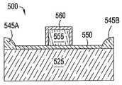
도 5A를 참조하면, 능동 전자 소자의 제조는, 다른 소자들로부터 능동 전자 소자를 전기적으로 절연시키는 전기적 절연 구조를 형성함으로써 시작된다. McGraw-Hill Publishing Company 간행, S.M. Sze의 VLSI Technology, 제2판, 11장에 일반적으로 기재된 여러 형태의 전기 절연 구조가 존재하며, 상기 간행물은 본원에 참고문헌으로 포함된다. 일 버전에서, 약 2,000 Å의 두께를 갖는 필드 산화 물 층(비도시)이 전체 기판(525)상에 최초로 성장되고, 산화막의 일부는 소자의 전기적 능동 엘리먼트가 형성되는 노출된 영역들을 둘러싸는 필드 산화물 배리어(545A,B)를 형성하도록 제거된다. 노출된 영역들은 약 50 내지 300 Å의 두께를 갖는 얇은 게이트 산화물 층(550)을 형성하도록 열 산화된다. 다결정 층이 그 후 증착되고, 패터닝되고, 에칭되어 게이트 전극(555)을 생성한다. 다결정 게이트 전극(555)의 표면은 재산화되어 절연 유전층(560)을 형성하며, 도 5A에 도시된 구조를 제공한다.Referring to FIG. 5A, fabrication of an active electronic device begins by forming an electrically insulating structure that electrically insulates the active electronic device from other devices. McGraw-Hill Publishing Company Publishing, S.M. There are several forms of electrically insulating structures generally described in Sze's VLSI Technology, 2nd edition, chapter 11, which publications are incorporated herein by reference. In one version, a field oxide layer (not shown) having a thickness of about 2,000 GPa is first grown on the
도 5B를 참조하면, 다음으로 소스 및 드레인(570A,B)이 적절한 도펀트 원자들로 적절한 영역들을 도핑함으로써 형성된다. 예를 들어, p형 기판(525)상에, 비소 또는 인을 포함한 n형 도펀트 종이 사용된다. 일반적으로 도핑은 이온 주입기에 의해 수행되며, 예를 들어, 약 1013 원자/cm2의 농도 및 약 30 내지 80 Kev의 에너지 레벨의 인(31P), 또는 약 1015 내지 1017원자/cm2의 양(doze) 및 약 10 내지 100 Kev의 에너지 레벨의 비소(75AS)를 포함할 수 있다. 주입 프로세스 이후에, 도펀트는 기판을 가령 급속 열처리(RTP) 장치에서 가열함으로써 기판(525)상에 주입된다. 그 후, 소스 및 드레인 영역(570A,B)을 덮고 있는 산화물 층(550)은, 주입 프로세스에 의해 발생되고 산화물 층에 포획되어 있는 불순물들을 제거하도록 종래의 스트리핑(stripping) 프로세스에 의해 스트리핑되어, 도 5B에 도시된 구조를 제공한다.Referring to FIG. 5B, source and drain 570A, B are next formed by doping the appropriate regions with suitable dopant atoms. For example, on the p-
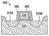
도 5C 및 5D를 참조하면, SiH2, Cl2, 및 NH3의 가스 혼합물을 이용하여 저압 화학기상증착(LPCVD)에 의해 게이트 전극(555) 및 기판(525) 위의 표면상에 실리콘 질화물 층(575)이 증착된다. 실리콘 질화물 층(575)은 그 후 도 5D에 도시된 것처럼 게이트 전극(555)의 측벽 위에 질화물 스페이서(580)를 형성하도록 반응성 이온 에칭(RIE) 기법을 이용하여 에칭된다. 스페이서(580)는 소스(570A) 및 드레인(570B) 위에 증착된 다른 실리사이드 층들로부터 게이트 전극(555)의 상부면에 형성된 실리사이드 층을 전기적으로 절연시킨다. 전기 절연 측벽 스페이서(580)와 상부층들은 가령 실리콘 산화물과 같은 다른 물질들로부터 제조될 수 있음에 주의하여야 한다. 측벽 스페이서(580)를 형성하기 위해 사용된 실리콘 산화물 층은 일반적으로 약 600℃ 내지 약 1,000℃의 온도에서 테트라에톡시실란(TEOS)의 공급 가스(feed gas)로부터 CVD 또는 PECVD에 의해 증착된다.5C and 5D, a silicon nitride layer on the surface over the
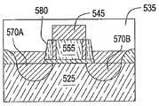
도 5E를 참조하면, 프로세스들 이전 및 이후에 대기에 노출시킴으로써 자연 실리콘 산화물 층(585)이 노출된 실리콘 표면들에 형성된다. 자연 실리콘 산화물 층(585)은, 합금 반응 및 형성된 금속 실리사이드의 전기 전도성을 향상시키기 위하여, 게이트(555), 소스(570A), 및 드레인(570B)상에 전도성 금속 실리사이드 콘택을 형성하기 전에 제거되어야 한다. 자연 실리콘 산화물 층(585)은 반전도 물질의 전기 저항을 증가시킬 수 있고, 이후에 증착되는 실리콘과 금속 층들의 실리사이드화(silicidation) 반응에 악영향을 줄 수 있다. 따라서, 능동 전자 소자를 상호연결(interconnecting)하기 위한 금속 실리사이드 콘택 또는 전도체를 형성하기 전에 이러한 자연 실리콘 산화물 층(585)을 전술된 건식 에칭 프로세스를 이용하여 제거하는 것이 필요하다. 건식 에칭 프로세스는 도 5F에 도시된 것처럼 소스(570A), 드레인(570B), 및 게이트 전극(555)의 상부면을 노출시키기 위하여 자연 실리콘 산화물 층(585)을 제거한다.Referring to FIG. 5E, a native
그 후, 도 5G에 도시된 것처럼, PVD 스퍼터링 프로세스가 사용되어 금속(590) 층을 증착한다. 종래의 노 어닐링이 그 후 사용되어 금속 및 실리콘 층을 어닐링하여, 금속 층(590)이 실리콘과 접촉하는 영역에 금속 실리사이드를 형성한다. 어닐링은 개별 프로세싱 시스템에서 일반적으로 수행된다. 따라서, 보호 캡 층(비도시)이 금속(590) 상부에 증착될 수 있다. 캡 층은 일반적으로 질화물 물질이며 티타늄, 질화물, 텅스텐 질화물, 탄탈 질화물, 하프늄 질화물, 및 실리콘 질화물을 포함하는 군으로부터 선택된 하나 이상의 물질들을 포함할 수 있다. 캡 층은 임의의 증착 프로세스에 의해, 바람직하게는 PVD에 의해 증착될 수 있다.Thereafter, a PVD sputtering process is used to deposit the
다음으로, 벌크 금속이 벌크 필(535)로써 도 5I에 도시된 것처럼 증착된다. 벌크 금속은 텅스텐 또는 일부 다른 금속일 수 있다.Next, bulk metal is deposited as bulk fill 535 as shown in FIG. 5I. The bulk metal may be tungsten or some other metal.
어닐링은 일반적으로 약 30분 동안 질소의 분위기에서 600℃ 내지 800℃의 온도로 기판(500)을 가열하는 것을 포함한다. 대안으로 금속 실리사이드(595)는, 기판(500)이 약 30초 동안 약 1000℃로 급속하게 가열되는 급속 열 어닐링 프로세스를 이용하여 형성될 수 있다. 적절한 전도성 금속은 코발트, 티타늄, 니켈, 텅스텐, 플라티늄, 및 낮은 접촉 저항을 가지며 다결정 및 단결정 실리콘 모두에 대해 신뢰할 수 있는 금속 실리사이드 콘택을 형성할 수 있는 임의의 다른 금속을 포 함한다.Annealing generally involves heating the
금속 층(590)의 반응되지 않은 부분들은 왕수(aqua regia)(HCl 및 HNO3)를 이용한 습식 에칭에 의해 제거될 수 있는데, 이는 금속 실리사이드(595); 스페이서(580), 또는 필드 산화물(545A,B)을 공격하지 않고 금속을 제거하며, 따라서 도 5H에 도시된 것처럼 게이트 전극(555), 소스(570A), 및 드레인(570B)상에 자기 정렬된 금속 실리사이드 콘택(595)을 남긴다. 그 후, 가령 실리콘 산화물, BPSG, 또는 PSG를 포함하는 절연 커버층이 전극 구조 상부에 증착될 수 있다. 절연 커버층은 CVD 챔버에서 화학기상증착을 이용하여 증착되며, 여기서 물질은 낮은 압력 또는 대기 압력에서 공급 가스로부터 응축하며, 이는 예를 들면 1996년 3월 19일에 발행된 미국 특허 No. 5,500,249에 기재되어 있으며, 이 문헌은 참고문헌으로 본원에 포함된다. 그 후, 구조(500)는 부드럽고 평탄화된 표면을 형성하도록 유리 전이 온도에서 어닐링된다.Unreacted portions of
하나 이상의 실시예에서, 프로세싱 챔버(100)는 캘리포니아 산타클라라 소재의 어플라이드 머티어리얼스 사로부터 입수가능한 EnduraTM와 같은 멀티 프로세싱 플랫폼으로 일체화될 수 있다. 이러한 프로세싱 플랫폼은 진공을 파괴하지 않고 여러 프로세싱 동작들을 수행할 수 있다. EnduraTM플랫폼의 상세는 발명의 명칭이 "Integrated Modular Processing Platform"이며, 1999년 11월 30일에 출원된 미국특허출원 일련번호 09/451,628에 기재되어 있고, 이 문헌은 참고문헌으로 본원에 포함된다.In one or more embodiments, the
도 6은 예시적인 멀티 챔버 프로세싱 시스템(600)의 평면도이다. 시스템(600)은 시스템(600) 내부 및 외부로 기판들을 이송하기 위한 하나 이상의 로드락 챔버(602, 604)를 포함한다. 일반적으로, 시스템(600)은 진공하에 있으므로, 로드락 챔버(602, 604)는 시스템(600)으로 도입된 기판들을 "펌프다운(pump down)"할 수 있다. 제1 로봇(610)은 로드락 챔버(602, 604)와 제1 집합의 하나 이상의 기판 처리 프로세싱 챔버(612, 614, 616, 618)(네 개가 도시됨) 사이에서 기판을 이송한다. 각 프로세싱 챔버(612, 614, 616, 618)는 본원에 기재된 건식 에칭 프로세스와 더불어, 순환형 층 증착(CLD), 원자층 증착(ALD), 화학기상증착(CVD), 물리기상증착(PVD), 에칭, 선 세정(pre-clean), 탈 가스(degas), 배향 및 다른 기판 프로세스를 포함하는 다수의 기판 프로세싱 동작들을 수행하도록 준비될 수 있다.6 is a top view of an example
제1 로봇(610)은 하나 이상의 이송 챔버(622, 624)로/로부터 기판을 이송할 수도 있다. 이송 챔버(622, 624)는 극대의 진공 조건을 유지하면서 기판들이 시스템(600) 내부에 전달되도록 사용될 수 있다. 제2 로봇(630)은 이송 챔버(622, 624)와 제2 집합의 하나 이상의 프로세싱 챔버(632, 634, 636, 및 638) 사이에서 기판들을 이송할 수 있다. 프로세싱 챔버(612, 614, 616, 618)와 유사하게, 프로세싱 챔버(632, 634, 636, 및 638)는 본원에 기재된 건식 에칭 프로세스와 더불어, 예를 들어 순환형 층 증착(CLD), 원자층 증착(ALD), 화학기상증착(CVD), 물리기상증착(PVD), 에칭, 선 세정(pre-clean), 탈 가스(degas), 배향 및 다른 기판 프로세스를 포함하는 다수의 기판 프로세싱 동작들을 수행하도록 준비될 수 있다. 시스템(600)에 의해 수행될 특정 프로세스에 대해 필요하지 않다면 임의의 기판 프로세 싱 챔버(612, 614, 616, 618, 632, 634, 636, 및 638)가 시스템(600)으로부터 제거될 수 있다.The
도 5A-5H의 MOSFET 구조를 형성하기 위한 예시적인 멀티 프로세싱 시스템(600)은 전술한 두 개의 프로세싱 챔버(100)와, 금속(500)을 증착하기 위한 두 개의 물리기상증착 챔버와, 선택적은 캡층(비도시)을 증착하기 위한 두 개의 물리기상증착 챔버를 포함한다. 도 6에 도시된 임의의 프로세싱 챔버(612, 614, 616, 618, 632, 634, 636, 및 638)가 PVD 챔버 및/또는 프로세싱 챔버(100)를 나타낸다.
비록 위의 프로세스 시퀀스가 MOSFET의 형성과 관련하여 기재되었지만, 본원에 기재된 건식 에칭 프로세스는 다른 금속 실리사이드 층, 가령 텅스텐, 탄탈, 몰리브덴의 실리사이드를 갖는 다른 반도체 구조 및 소자를 형성하기 위해 사용될 수도 있다. 세정 프로세스가 가령 알루미늄, 구리, 코발트, 니켈, 실리콘, 티타늄, 팔라듐, 하프늄, 붕소, 텅스텐, 탄탈, 또는 이들의 조합을 포함하는 서로 다른 금속들의 층의 증착 이전에 사용될 수도 있다.Although the above process sequence has been described in connection with the formation of MOSFETs, the dry etching process described herein may be used to form other semiconductor structures and devices having silicides of other metal silicide layers such as tungsten, tantalum, molybdenum. The cleaning process may be used prior to the deposition of a layer of different metals including, for example, aluminum, copper, cobalt, nickel, silicon, titanium, palladium, hafnium, boron, tungsten, tantalum, or a combination thereof.
도 7은 프로세싱 챔버(700)의 일 실시예를 도시하는 부분단면도이다. 이 실시예에서, 프로세싱 챔버(700)는 챔버 몸체(712)의 상단부에 배치된 리드 어셈블리(701)와, 챔버 몸체(712) 내에 적어도 부분적으로 배치된 지지 어셈블리(710)를 포함한다. 프로세싱 챔버는 또한 도 8에 추가적으로 기재될 U 형상 단면을 갖는 원격 전극을 갖는 원격 플라즈마 발생기(740)도 포함한다. 챔버(700)와 관련 하드웨어는 하나 이상의 프로세스 호환가능한 물질, 가령 알루미늄, 양극산화 처리된 알루미늄, 니켈 도금 알루미늄, 니켈 도금 알루미늄 6061-T6, 스테인리스 강, 및 이들의 조합 및 합금들으로부터 형성되는 것이 바람직하다.7 is a partial cross-sectional view illustrating one embodiment of a
지지 어셈블리(710)는 챔버 몸체(712)내에 적어도 부분적으로 배치된다. 지지 어셈블리(710)는 벨로우즈(733)에 의해 둘러싸인 샤프트(비도시)에 의해 승강된다. 챔버 몸체(712)는 프로세싱 챔버(700) 내부로의 액세스를 제공하는, 측벽에 형성된 슬릿 밸브(760)를 포함한다. 슬릿 밸브(760)는 웨이퍼 처리 로봇(비도시)에 의해 챔버 몸체(712)의 내부로의 액세스를 가능하게 하기 위하여 선택적으로 개폐된다. 웨이퍼 처리 로봇은 당업자에게 주지되어 있고, 임의의 적합한 로봇이 사용될 수 있다. 일 실시예에서, 웨이퍼는 슬릿 밸브 개구(760)를 통해서 인접한 이송 챔버 및/또는 로드락 챔버(비도시)로, 또는 클러스터 툴 내부의 또 다른 챔버로, 프로세싱 챔버(700) 내외부로 이송될 수 있다. 예시적인 클러스터 툴은 캘리포니아 산타클라라 소재의 어플라이드 머티어리얼스 사로부터 입수가능한 PRODUCERTM, CENTURETM, ENDURATM, 및 ENDURASLTM플랫폼을 포함하나 이에 제한되지는 않는다.The
챔버 몸체(112)는 챔버 몸체 내부에 형성되며 열 전달 유체를 유동시키기 위한 채널(비도시)을 포함한다. 열 전달 유체는 가열 유체 또는 냉각제일 수 있고, 프로세싱 및 기판 이송 동안 챔버 몸체(712)의 온도를 제어하기 위해 사용된다. 챔버 몸체(712)의 온도는 챔버 벽에 가스 또는 부산물의 원치 않는 응축을 방지하기 위해 중요하다. 예시적인 열 전달 유체는 물, 에틸렌글리콜, 또는 이들의 혼합물을 포함한다. 예시적인 열 전달 유체는 질소 가스를 포함할 수도 있다.The
챔버 몸체(712)는 또한 지지 어셈블리(700)를 둘러싸는 라이너(733)를 포함하며, 서비스 및 세정을 위해 제거가능하다. 라이너(733)는 바람직하게는 알루미늄, 또는 세라믹 물질과 같은 금속으로 제조된다. 그러나, 임의의 프로세스 호환가능한 물질이 사용될 수 있다. 라이너(733)는 여기에 증착되는 임의의 물질의 부착을 증진시키기 위하여 비드 블래스트(bead blast)될 수 있으며, 이에 의해 프로세싱 챔버(700)의 오염에 이르게 될 물질의 벗겨져 떨어짐(flaking)을 방지한다. 라이너(733)는 일반적으로 진공 시스템과 유체 소통되며 라이너 내부에 형성된 펌핑 채널(729)과 하나 이상의 구멍(735)을 포함한다. 구멍은 펌핑 채널(729)로 유입되는 가스들을 위한 유동 경로를 제공하며, 펌핑 채널(729)은 가스들이 챔버(700)로부터 배출되도록 라이너(733)를 통해 유동 경로를 제공한다.The
진공 시스템은 챔버(700)내의 가스들의 유동을 조절하기 위하여 진공 펌프(비도시)와 스로틀밸브(비도시)를 포함한다. 진공 펌프는 챔버 몸체(712)에 배치된 진공 포트(비도시)와 연결되며, 라이너(733)내에 형성된 펌핑 채널(729)과 유체 소통한다. 진공 펌프와 챔버 몸체(712)는 챔버(700)내의 가스들의 유동을 조정하기 위하여 스로틀 밸브에 의해 선택적으로 격리된다. 용어 "가스"와 "가스들"은 달리 지적되지 않는 한 상호교환하여 사용될 수 있으며, 하나 이상의 전구체, 반응체, 촉매, 캐리어, 정화, 세정, 이들의 조합과, 챔버 몸체(712)로 유입되는 임의의 다른 유체를 말한다.The vacuum system includes a vacuum pump (not shown) and a throttle valve (not shown) to regulate the flow of gases in the
리드 어셈블리(700)는 서로의 상부에 적층된 다수의 컴포넌트들을 포함한다. 예를 들어, 리드 어셈블리(700)를 리드 림(710), 가스 전달 어셈블리(720), 및 상 부 플레이트(750)를 포함한다. 리드 림(710)은 리드 어셈블리(700)를 구성하는 컴포넌트들의 하중을 견디도록 설계되며 가령 지지 어셈블리(300)와 같은 내부 챔버 컴포넌트들에 액세스를 제공하기 위하여 힌지 어셈블리(이 도면에는 비도시)를 통하여 챔버 몸체(712)의 상부면에 결합된다. 가스 전달 어셈블리(720)는 리드 림(710)의 상부면에 결합되며 리드 림과 최소한의 열 접촉을 이루도록 배치된다. 리드 어셈블리(700)의 컴포넌트들은 가령 잘 마감된 표면을 갖는 알루미늄 합금과 같이 높은 열전도성과 낮은 열 저항을 갖는 물질로 제조되는 것이 바람직하다. 컴포넌트들의 열 저항은 약 5×10⁻⁴㎡ K/W보다 작은 것이 바람직하다.The
가스 전달 어셈블리(720)를 보다 상세히 고려하면, 가스 전달 어셈블리(720)는 분배 플레이트 또는 샤워헤드를 포함한다. 가스 공급 패널(비도시)은 일반적으로 프로세싱 챔버(700)에 하나 이상의 가스들을 제공하기 위해 사용된다. 사용되는 특정 가스 또는 가스들은 챔버(700)내에서 수행될 프로세스에 따른다. 예를 들어, 특정 가스들은 하나 이상의 전구체, 환원제, 촉매, 캐리어, 정화, 세정, 또는 이들의 임의의 혼합물 또는 조합을 포함한다. 일반적으로, 상기 하나 이상의 가스들은 프로세싱 챔버(700)로 도입되어 리드 어셈블리(700)로 흐르며 그 후 가스 전달 어셈블리(720)를 통해 챔버 몸체(712)로 흐른다. 전기적으로 동작되는 밸브 및/또는 유동 제어 메커니즘(비도시)이 사용되어 가스 공급부로부터 챔버(700)로의 가스의 흐름을 제어할 수 있다.Considering the
일 측면에서, 가스는 가스 박스(비도시)로부터 챔버(700)로 전달되며, 가스 라인은 전술한 것처럼 가스를 챔버 몸체(712)에 공급하기 위하여 두 개의 개별 가스 라인으로 분기한다. 프로세스에 따라서, 임의의 수의 가스들이 이러한 방식으로 전달될 수 있고 챔버(700) 내에서 또는 이들이 챔버(700)에 전달되기 전에 혼합될 수 있다.In one aspect, gas is delivered from a gas box (not shown) to the
계속 도 7을 참조하면, 리드 어셈블리는 리드 어셈블리(700)내에 반응종의 플라즈마를 생성하기 위해 전극(740)을 더 포함할 수 있다. 일 실시예에서, 전극(740)은 상부 플레이트(750)상에 지지되며 이로부터 전기적으로 절연된다. 상부 플레이트(750)로부터 전극(740)을 분리하는 절연 필터 링이 전극(740)의 하부 주변에 배치될 수 있다. 환형 절연체(비도시)가 또한 절연 필터 링의 외부에 대해 배치되며 도 1에 도시된 것처럼 상부 플레이트(750)의 상부면상에 안착된다. 환형 절연체(비도시)는 그 후 전극(740)의 상부 주변에 배치되어 RF 플레이트(740)가 리드 어셈블리(700)의 다른 요소들로부터 전기적으로 절연된다. 이러한 링들 각각, 절연 필터, 및 환형 절연체는 알루미늄 산화물이나 임의의 다른 절연체, 프로세스 호환가능한 물질로 제조될 수 있다.With continued reference to FIG. 7, the lead assembly may further include an
전극(740)은 전력 소스(미도시)에 연결되며 가스 전달 어셈블리(720)는 그라운드에 연결된다. 따라서, 하나 이상의 프로세스 가스들의 플라즈마는 전극(740)과 가스 전달 어셈블리(720) 사이에 형성된 부피에서 타격될 수 있다. 차단기 플레이트 어셈블리가 없는 경우에, 플라즈마는 전극(740)과 차단기 어셈블리(720) 사이에서 타격(striking) 및 함유될 수 있다. 대안으로, 플라즈마는 차단기 어셈블리가 없을 때는, 전극(740)과 가스 전달 어셈블리(720) 사이에서 타격 및 함유될 수 있다. 또 다른 실시예에서, 플라즈마는 리드 어셈블리(710)내에 양호하게 한정되고 함유될 수 있다.
가스들을 반응종으로 활성화할 수 있고 반응종들의 플라즈마를 유지할 수 있는 임의의 전력 소스가 사용될 수 있다. 예를 들어, 전력 방전 기법에 기초하여 무선 주파수(RF), 직류(DC), 교류(AC) 또는 마이크로파(MW)가 사용될 수 있다. 활성화는 열 기반 기법, 가스 방전(breakdown) 기법, 고밀도 광소스(예, UV 에너지), 또는 x-레이 소스로의 노광에 의해 생성될 수도 있다. 대안으로, 원격 플라즈마 발생기와 같은 원격 활성화 소스가 사용되어, 챔버(700)로 전달될 반응종들의 플라즈마를 생성할 수 있다. 예시적인 원격 플라즈마 발생기들은 MKS instruments Inc. 및 Advanced Energy Industries, Inc.와 같은 판매자로부터 이용가능하다. 바람직하게는, RF 전력 공급이 전극(240)에 연결된다.Any power source that can activate the gases as reactive species and maintain a plasma of the reactive species can be used. For example, radio frequency (RF), direct current (DC), alternating current (AC) or microwave (MW) may be used based on the power discharge technique. Activation may be generated by heat-based techniques, gas breakdown techniques, high density light sources (eg, UV energy), or exposure to x-ray sources. Alternatively, a remote activation source, such as a remote plasma generator, may be used to generate a plasma of reactive species to be delivered to the
가스 전달 어셈블리(720)는 프로세스 가스들, 및 프로세싱 챔버(700)내에서 수행될 동작들에 의존하여 가열될 수 있다. 일 실시예에서, 가열 엘리먼트(770), 가령 저항성 가열기는 가스 분배 플레이트(725)에 결합될 수 있다. 일 실시예에서, 가열 엘리먼트(770)는 튜브형 부재이며 가스 전달 어셈블리(720)의 상부면에 압축된다. 가스 전달 어셈블리(720)의 상부면은 가열 엘리먼트(770)의 외부 직경보다 약간 작은 폭을 갖는 그루브 또는 오목한(recessed) 채널을 포함하여, 가열 엘리먼트(770)는 계면 접합을 이용하여 그루브내에 유지된다.The
가스 전달 어셈블리(720)와 차단기 어셈블리(730)를 포함하는 전달 어셈블리(220)의 컴포넌트들 각각이 상호 도전 결합되어 있으므로, 가열 엘리먼트(770)는 가스 전달 어셈블리(720)의 온도를 조정한다. 프로세싱 챔버의 부가적인 상세는 2005년 2월 22일에 출원된 미국 특허출원 번호 11/063,645에서 발견될 수 있으며, 이 문헌은 참고문헌으로 본원에 포함된다.Since each of the components of the
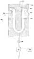
도 8은 원격 플라즈마 발생기(840)의 컴포넌트들을 도시한다. 유입구(841)는 발생기(840)에 가스를 공급한다. 절연체(842)는 그라운드(844)로부터 전극(843)을 절연시킨다. 챔버(845)는 플라즈마가 점화하여 밸브(846) 쪽으로 유동하는 영역을 제공한다. 밸브는 부가적인 가스 공급부(848)에 연결되어 있는 혼합 영역과 유체 소통한다. 플라즈마와 가스들은 밸브(846)로부터 리드 어셈블리로 흐를 수 있다. U 형상의 전극(843) 및 챔버(845)는 비율로 정의될 수 있는 기하구조 특성을 갖는다. 예를 들어, 챔버의 부피에 대한 전극의 표면적의 비는, 전극과 챔버의 높이 및 폭과 같은 필적할만한 치수들을 갖는 원통형 또는 직사각형의 챔버에 하우징되는 전통적인, 원통형, 구형, 또는 직사각형의 전극보다 크다. 또한, 챔버의 벽의 표면적에 대한 전극의 표면적의 비도 전극과 챔버의 높이 및 폭과 같은 필적할만한 치수들을 갖는 원통형 또는 직사각형의 챔버에 하우징되는 전통적인, 원통형, 구형, 또는 직사각형의 전극보다 U 형상 전극에 대해 더 크다.8 shows components of a
장기의 사용기간 이후에 또는 예정된 유지보수를 위한 지정 시기에, 전술한 챔버(700)의 특정 요소들은 정기적으로 검사되거나, 교체되거나, 세정된다. 이러한 요소들은 일반적으로 "프로세스 키트"로 집합적으로 알려져 있는 부품들이다. 보다 구체적으로, 프로세스 키트는 예를 들어 가스 전달 어셈블리(720), 상부 플레이트(비도시), 에지 링(비도시), 라이너(733), 및 승강 핀(비도시)을 포함하나 이 에 제한되지는 않는다. 임의의 하나 이상의 이러한 요소들은 일반적으로 정기적인 간격으로 또는 필요에 따라서 챔버(700)로부터 제거되고 세정되거나 교체된다.After prolonged service periods or at designated times for scheduled maintenance, certain elements of the
또한, 프로세싱 챔버(700)는 캘리포니아 산타클라라 소재의 어플라이드 머티어리얼스 사로부터 입수가능한 EnduraTM와 같은 멀티 프로세싱 플랫폼으로 일체화될 수 있다. 이러한 프로세싱 플랫폼은 진공을 파괴하지 않고 여러 프로세싱 동작들을 수행할 수 있다. EnduraTM플랫폼의 상세는 미국특허번호 6,558,509에 기재되어 있고, 이 문헌은 참고문헌으로 본원에 포함된다.In addition, the
기재의 간소화 및 용이화를 위해, 프로세싱 챔버(700)내에서 수행된 암모니아(NH3)와 삼불화질소(NF3) 가스 혼합물을 이용하여 실리콘 산화물을 제거하는 예시적인 건식 에칭 프로세스가 기재될 것이다. 프로세싱 챔버(700)는, 어닐링 프로세스를 포함하는 단일 프로세싱 환경 내에서 기판 가열과 냉각뿐만 아니라 플라즈마 처리로부터도 이익을 얻을 수 있는 어떠한 건식 에칭 프로세스에 대해서도 유리하다고 여겨진다.For simplicity and ease of substrate, an exemplary dry etching process will be described that removes silicon oxide using ammonia (NH3 ) and nitrogen trifluoride (NF3 ) gas mixtures performed in the
도 7을 참조하면, 건식 에칭 프로세스는 가령 반도체 기판과 같은 기판(비도시)을 프로세싱 챔버(700)로 배치함으로써 시작된다. 기판은 일반적으로 슬릿 밸브 개구(760)를 통해 챔버 몸체(712)로 배치되며 지지 부재(710)의 상부면에 위치된다. 기판은 지지 부재(710)의 상부면상으로 척킹(chucking)된다. 바람직하게는, 기판은 진공 펌프와 유체 소통하는 홀 및 그루브를 통해 진공을 뽑아냄(pulling a vacuum)으로써 지지 부재(710)의 상부면에 척킹된다. 지지 부 재(710)는 그 후 프로세싱 위치에 있지 않다면 챔버 몸체(712)내에서 프로세싱 위치로 상승된다. 챔버 몸체(712)는 바람직하게는 50℃ 내지 80℃, 더욱 바람직하게는 약 65℃의 온도에서 유지된다. 이러한 챔버 몸체(712)의 온도는 챔버 몸체(712)의 벽을 통해 열 전달 매체를 통과시킴으로써 유지된다.Referring to FIG. 7, the dry etching process begins by placing a substrate (not shown), such as a semiconductor substrate, into the
기판은 지지 어셈블리(700)내에 형성된 유체 채널(비도시)을 통해 열 전달 매체 또는 냉각제를 통과시킴으로써 65℃이하, 가령 15℃ 내지 50℃로 냉각된다. 일 실시예에서, 기판은 실온 이하로 유지된다. 다른 실시예에서, 기판은 22℃ 내지 40℃의 온도로 유지된다. 전형적으로 지지 부재(710)는 위에서 구체화된 원하는 기판 온도에 도달하도록 약 22℃ 미만으로 유지된다. 지지 부재(310)를 냉각시키기 위하여, 냉각제가 지지 부재(310)내의 유체 채널을 통해 통과된다. 냉각제의 연속적인 흐름이 지지 부재(310)의 온도를 더 잘 제어하는 데 바람직하다. 냉각제는 부피에 있어서 에틸렌글리콜이 50퍼센트이고 물이 50퍼센트인 것이 바람직하다. 물론, 기판의 원하는 온도가 유지되는 한 임의의 비의 물과 에틸렌글리콜이 사용될 수 있다.The substrate is cooled to 65 ° C. or less, such as 15 ° C. to 50 ° C., by passing a heat transfer medium or coolant through a fluid channel (not shown) formed in the
암모니아와 삼불화질소는 그 후 세정 가스 혼합물을 형성하도록 챔버(700)로 도입된다. 챔버로 도입된 각각의 가스의 양은 가변적이며 가령 제거될 산화물 층의 두께, 세정될 기판의 기하구조, 플라즈마의 부피 용량, 챔버 몸체(712)의 부피 용량, 및 챔버 몸체(712)에 결합된 진공 시스템의 용량을 수용하도록 조정될 수 있다. 일 측면에서, 가스들은 삼불화질소에 대한 암모니아의 적어도 1:1의 몰비를 갖는 가스 혼합물을 제공하도록 부가된다. 다른 측면에서, 가스 혼합물의 몰비는 적어도 약 3대 1(암모니아 대 삼불화질소)이다. 바람직하게는, 5:1(암모니아 대 삼불화질소) 내지 30:1의 몰비에서 챔버(700)로 가스들이 도입된다. 보다 바람직하게는, 가스 혼합물의 몰비는 약 5:1(암모니아 대 삼불화질소) 내지 약 10:1이다. 가스 혼합물의 몰비는 또한 약 10:1(암모니아 대 삼불화질소) 내지 약 20:1에 들 수 있다.Ammonia and nitrogen trifluoride are then introduced into
정화 가스 또는 캐리어 가스도 또한 가스 혼합물에 부가될 수 있다. 가령 아르곤, 헬륨, 수소, 질소, 및 이들의 혼합물과 같은 임의의 적절한 정화/캐리어 가스가 사용될 수 있다. 일반적으로, 전체 가스 혼합물은 부피 면에서 암모니아와 삼불화질소의 약 0.05% 내지 약 20%이다. 나머지는 캐리어 가스이다. 일 실시예에서, 정화 또는 캐리어 가스가 챔버 몸체(712) 내부의 압력을 안정화하기 위하여 반응 가스들 이전에 먼저 챔버 몸체(712)에 도입된다.Purification gas or carrier gas may also be added to the gas mixture. Any suitable purge / carrier gas can be used, such as, for example, argon, helium, hydrogen, nitrogen, and mixtures thereof. Generally, the total gas mixture is about 0.05% to about 20% of ammonia and nitrogen trifluoride in volume. The rest is carrier gas. In one embodiment, a purge or carrier gas is first introduced into the
챔버 몸체(712) 내부의 동작 압력은 가변적일 수 있다. 일반적으로, 압력은 약 100 mTorr 내지 약 30 Torr에서 유지된다. 바람직하게는, 압력은 약 200 Torr 내지 약 5 Torr에서 유지된다.The operating pressure inside the
약 5 내지 약 600 Watt의 RF 전력이 전극(840)에 인가되어 가스 전달 어셈블리(720)에 포함된 부피들내부에 가스 혼합물의 플라즈마를 점화한다. 바람직하게는, RF 전력이 100 Watt 미만이다. 보다 바람직하게는 전력이 인가되는 주파수가 가령 20 kHz 미만과 같이 매우 낮다.RF power of about 5 to about 600 Watts is applied to the
플라즈마 에너지는 암모니아와 삼중화불소를 반응성 종들로 분해하며, 이 반 응성 종들이 결합하여 상당히 반응성인 암모니아 불소(NH4F) 화합물 및/또는 암모니아 수소 불소(NH4F·HF)를 가스 상태로 형성한다. 이러한 분자들은 그 후 홀들(비도시)을 경유하여 가스 전달 어셈블리(220)를 통해 흘러 세정될 기판 표면과 반응한다. 일 실시예에서, 캐리어 가스가 먼저 챔버(700)로 도입되고, 캐리어 가스의 플라즈마가 발생되고, 그 후 반응 가스들, 암모니아, 및 삼불화질소가 이 플라즈마에 부가된다.Plasma energy decomposes ammonia and fluorine tritide into reactive species, which combine to form a highly reactive ammonia fluoride (NH4 F) compound and / or ammonia hydrogen fluoride (NH4 FHF) in a gaseous state. Form. These molecules then flow through the
이론에 제한되기를 바라지 않으며, 에천트(etchant) 가스, NH4F, 및/또는 NH4F·HF는 실리콘 산화물 표면과 반응하여 암모늄 헥사플루오로실리케이트 (NH4)2SiF6, NH3, 및 H2O 생성물을 형성한다고 여겨진다. NH3, 및 H2O는 프로세싱 조건에서 증발하여 진공 펌프(125)에 의해 챔버(100)로부터 제거된다. 특히, 휘발성 가스들은 가스들이 진공 포트(비도시)를 통해 진공 펌프로 배출되기 전에 라이너(733)에 형성된 구멍들(735)을 통해 펌핑 채널(729)로 흐른다. (NH4)2SiF6의 박막이 기판면 뒤에 남는다. 반응 메커니즘은 다음과 같이 요약될 수 있다:Without wishing to be bound by theory, etchant gases, NH4 F, and / or NH4 F.HF react with the silicon oxide surface to react ammonium hexafluorosilicate (NH4 )2 SiF6 , NH3 , and It is believed to form an H2 O product. NH3 , and H2 O are removed from
막이 기판 표면에 형성된 후에, 기판이 그 상부에 지지된 지지 부재(710)가 가열된 가스 전달 어셈블리(720)에 인접한 어닐 위치로 상승된다. 가스 전달 어셈블리(720)로부터 방사된 열은 (NH4)2SiF6의 박막을 SiF4, NH3, 및 HF 생성물로 해리 또는 승화시키기에 충분해야 한다. 이러한 휘발성 생성물들은 그 후 전술한 것처럼 진공 펌프에 의해 챔버(100)로부터 제거된다.After the film is formed on the substrate surface, the
(NH4)2SiF6의 박막을 휘발성 요소들로 해리시키기 위한 열 에너지는 가스 전달 어셈블리(720)에 의해 대류되거나 방사된다. 상부에 박막을 갖는 기판의 상부면과 가스 전달 어셈블리(720) 사이의 거리는 중요하지 않으며 일상적인 실험의 문제이다. 당업자는 하부의 기판에 손상을 주지 않고 박막을 효율적이고 효과적으로 증발시키는 데 필요한 이격을 쉽게 결정할 수 있다. 그러나, 약 0.254mm (10mil) 내지 5.08mm (200mil)의 이격이 효과적이라고 여겨진다.Thermal energy for dissociating the thin film of (NH4 )2 SiF6 into volatile elements is convection or radiated by the
일단 막이 기판으로부터 제거되었다면, 챔버는 정화되고 배기된다. 세정된 기판은 그 후 기판을 이송 위치로 하강시키고, 기판을 디척킹(de-chucking)하고, 기판을 슬릿 밸브 개구(760)를 통해 이송함으로써 챔버 몸체(112)로부터 제거된다.Once the film has been removed from the substrate, the chamber is purged and evacuated. The cleaned substrate is then removed from the
시스템 제어기(비도시)는 프로세싱 챔버(100)의 동작을 조정하기 위해 사용될 수 있다. 시스템 제어기는 컴퓨터의 하드디스크 드라이브상에 저장된 컴퓨터 프로그램의 제어하에 동작될 수 있다. 컴퓨터 프로그램은 프로세스 시퀀싱 및 타이밍, 가스들의 혼합, 챔버압, RF 전력 레벨, 서셉터 위치 지정, 슬릿 밸브 개폐, 물 냉각 및 특정 프로세스의 다른 매개변수들을 지시할 수 있다. 사용자와 시스템 제어기간의 인터페이스는 CRT 모니터 및 광펜(비도시)을 통해 이루어진다. 바람직한 실시예에서, 두 개의 모니터가 사용되며, 하나의 모니터는 작동자를 위해 클린 룸에 장착되고 다른 모니터는 서비스 기술자들을 위해 벽 뒤에 장착된다.A system controller (not shown) can be used to coordinate the operation of the
전술한 논의의 더 나은 이해를 제공하기 위하여, 다음의 비 제한적인 예가 제공된다. 본 예는 특정 실시예에 관한 것이나, 본 예는 어떠한 구체적인 관점에서도 본 발명을 제한하는 것으로 해석되지 않아야 한다.In order to provide a better understanding of the foregoing discussion, the following non-limiting examples are provided. This example is directed to specific embodiments, but this example should not be construed as limiting the invention in any specific respect.
예:Yes:
에칭 동안, 2 sccm의 NF3, 10 sccm의 NH3 및 2,500 sccm의 아르곤의 가스 혼합물이 챔버로 도입되었다. 가스 혼합물의 플라즈마는 100 Watt의 전력을 이용하여 점화되었다. 하부 정화는 1,500 sccm의 아르곤이었고, 에지 정화는 50 sccm의 아르곤이었다. 챔버압은 약 6 Torr에서 유지되었으며 기판 온도는 약 22℃였다. 기판은 120초 동안 에칭되었다.During etching, a gas mixture of 2 sccm NF3 , 10 sccm NH3 and 2,500 sccm argon was introduced into the chamber. The plasma of the gas mixture was ignited using 100 Watts of power. The bottom clarification was 1,500 sccm of argon and the edge clarification was 50 sccm of argon. The chamber pressure was maintained at about 6 Torr and the substrate temperature was about 22 ° C. The substrate was etched for 120 seconds.
이후의 어닐링 동안에, 이격은 750 mil이었고, 리드 온도는 120℃였다. 기판은 약 60초 동안 어닐링 되었다. 약 50Å의 물질이 기판 표면으로부터 제거되었다. 어떠한 어닐링 효과도 관측되지 않았다. 에칭 속도는 초당 0.46Å이었다(28Å/분). 관측된 에칭 균일도는 50Å 에칭에 대하여 약 5%였다.During subsequent annealing, the spacing was 750 mils and the read temperature was 120 ° C. The substrate was annealed for about 60 seconds. About 50 mm 3 of material was removed from the substrate surface. No annealing effect was observed. The etching rate was 0.46 kPa / sec (28 kPa / min). The observed etch uniformity was about 5% for a 50 Hz etch.
세정 방식의 이점은 어떠한 부가적인 프로세싱 장비도 필요하지 않으며 습식 세정을 위하여 챔버를 개방할 필요가 없다는 것이다. 프로세스는 또한 일정한 모 니터링 또는 노동 집약을 요하지 않고, 습식 세정과 관련된 시간 지연을 요하지 않는다. 즉, 차단된 냉각 유체 유입구를 가진 상승된 페데스털(pedestal)을 이용하여 세정하는 시간은, 페데스털 냉각 유체를 가열하는 세정 시스템에 대해 필요한 2 내지 3일과 비교하여, 약 5시간이다.The advantage of the cleaning scheme is that no additional processing equipment is required and the chamber does not need to be opened for wet cleaning. The process also does not require constant monitoring or labor intensiveness and does not require time delays associated with wet cleaning. That is, the cleaning time using an elevated pedestal with a blocked cooling fluid inlet is about 5 hours compared to the 2-3 days required for a cleaning system that heats the pedestal cooling fluid.
달리 언급되지 않는다면, 본 명세서와 청구범위에서 사용된 성분, 특성, 반응 조건, 등의 양을 표현하는 모든 숫자는 근사값으로 이해되어야 한다. 이러한 근사값은, 본 발명에 의해 얻어져야 하는 원하는 특성과 측정의 오차에 기초하며, 다수의 기록되어 있는 중요한 숫자의 관점에서 그리고 통상적인 반올림 기법을 적용하여 적어도 해석되어야 한다. 또한, 온도, 압력, 이격, 몰비, 유속 등을 포함하는 본원에 표현된 모든 양은 원하는 에칭 선택비 및 특정 성능을 얻기 위해 추가로 최적화될 수 있다.Unless stated otherwise, all numbers expressing quantities of ingredients, properties, reaction conditions, and the like used in the specification and claims are to be understood as approximations. This approximation is based on the desired characteristics and the error of the measurement to be obtained by the present invention and should be interpreted at least in terms of a number of significant figures recorded and by applying conventional rounding techniques. In addition, all amounts expressed herein, including temperature, pressure, spacing, molar ratio, flow rate, and the like, can be further optimized to obtain the desired etch selectivity and specific performance.
전술한 것이 본 발명의 실시예들에 관한 것이지만, 본 발명의 다른 추가적인 실시예들이 본 발명의 기본적인 사상을 일탈하지 않고 개량될 수 있으며, 그 범위는 다음의 청구범위에 의해 결정된다.While the foregoing is directed to embodiments of the present invention, other additional embodiments of the present invention may be improved without departing from the basic spirit thereof, and the scope thereof is determined by the following claims.
Claims (40)
Translated fromKoreanApplications Claiming Priority (6)
| Application Number | Priority Date | Filing Date | Title |
|---|---|---|---|
| US63789704P | 2004-12-21 | 2004-12-21 | |
| US60/637,897 | 2004-12-21 | ||
| US11/137,200US20060130971A1 (en) | 2004-12-21 | 2005-05-24 | Apparatus for generating plasma by RF power |
| US11/137,200 | 2005-05-24 | ||
| US11/266,167US20060051966A1 (en) | 2004-02-26 | 2005-11-03 | In-situ chamber clean process to remove by-product deposits from chemical vapor etch chamber |
| US11/266,167 | 2005-11-03 |
Publications (1)
| Publication Number | Publication Date |
|---|---|
| KR20070087196Atrue KR20070087196A (en) | 2007-08-27 |
Family
ID=36602275
Family Applications (1)
| Application Number | Title | Priority Date | Filing Date |
|---|---|---|---|
| KR1020077016827ACeasedKR20070087196A (en) | 2004-12-21 | 2005-12-20 | In-situ chamber cleaning method to remove byproduct deposition from chemical vapor etching chamber |
Country Status (3)
| Country | Link |
|---|---|
| EP (1) | EP1831430A2 (en) |
| KR (1) | KR20070087196A (en) |
| WO (1) | WO2006069085A2 (en) |
Cited By (4)
| Publication number | Priority date | Publication date | Assignee | Title |
|---|---|---|---|---|
| KR20130129943A (en)* | 2010-10-19 | 2013-11-29 | 어플라이드 머티어리얼스, 인코포레이티드 | Quartz showerhead for nanocure uv chamber |
| KR20150104513A (en)* | 2014-03-05 | 2015-09-15 | 램 리써치 코포레이션 | Waferless clean in dielectric etch process |
| KR20180094122A (en)* | 2016-01-13 | 2018-08-22 | 어플라이드 머티어리얼스, 인코포레이티드 | Hydrogen Plasma Based Cleaning Process for Etching Hardware |
| WO2020171958A1 (en)* | 2019-02-21 | 2020-08-27 | Lam Research Corporation | Macroscopic texturing for anodized and coated surfaces |
Families Citing this family (70)
| Publication number | Priority date | Publication date | Assignee | Title |
|---|---|---|---|---|
| US20070123051A1 (en)* | 2004-02-26 | 2007-05-31 | Reza Arghavani | Oxide etch with nh4-nf3 chemistry |
| US20050230350A1 (en)* | 2004-02-26 | 2005-10-20 | Applied Materials, Inc. | In-situ dry clean chamber for front end of line fabrication |
| US7780793B2 (en)* | 2004-02-26 | 2010-08-24 | Applied Materials, Inc. | Passivation layer formation by plasma clean process to reduce native oxide growth |
| US8450193B2 (en)* | 2006-08-15 | 2013-05-28 | Varian Semiconductor Equipment Associates, Inc. | Techniques for temperature-controlled ion implantation |
| US7655933B2 (en) | 2006-08-15 | 2010-02-02 | Varian Semiconductor Equipment Associates, Inc. | Techniques for temperature-controlled ion implantation |
| US20080142483A1 (en)* | 2006-12-07 | 2008-06-19 | Applied Materials, Inc. | Multi-step dep-etch-dep high density plasma chemical vapor deposition processes for dielectric gapfills |
| US7939422B2 (en)* | 2006-12-07 | 2011-05-10 | Applied Materials, Inc. | Methods of thin film process |
| US8211808B2 (en) | 2009-08-31 | 2012-07-03 | Applied Materials, Inc. | Silicon-selective dry etch for carbon-containing films |
| US9324576B2 (en) | 2010-05-27 | 2016-04-26 | Applied Materials, Inc. | Selective etch for silicon films |
| US8741778B2 (en) | 2010-12-14 | 2014-06-03 | Applied Materials, Inc. | Uniform dry etch in two stages |
| US8771539B2 (en) | 2011-02-22 | 2014-07-08 | Applied Materials, Inc. | Remotely-excited fluorine and water vapor etch |
| US8771536B2 (en) | 2011-08-01 | 2014-07-08 | Applied Materials, Inc. | Dry-etch for silicon-and-carbon-containing films |
| US8679982B2 (en) | 2011-08-26 | 2014-03-25 | Applied Materials, Inc. | Selective suppression of dry-etch rate of materials containing both silicon and oxygen |
| US8679983B2 (en) | 2011-09-01 | 2014-03-25 | Applied Materials, Inc. | Selective suppression of dry-etch rate of materials containing both silicon and nitrogen |
| US8927390B2 (en) | 2011-09-26 | 2015-01-06 | Applied Materials, Inc. | Intrench profile |
| US8808563B2 (en) | 2011-10-07 | 2014-08-19 | Applied Materials, Inc. | Selective etch of silicon by way of metastable hydrogen termination |
| WO2013070436A1 (en) | 2011-11-08 | 2013-05-16 | Applied Materials, Inc. | Methods of reducing substrate dislocation during gapfill processing |
| CN108565198A (en) | 2012-02-14 | 2018-09-21 | 恩特格里斯公司 | Carbon dopant gas and co-flow for improved implant beam and source lifetime performance |
| US9373517B2 (en) | 2012-08-02 | 2016-06-21 | Applied Materials, Inc. | Semiconductor processing with DC assisted RF power for improved control |
| US9034770B2 (en) | 2012-09-17 | 2015-05-19 | Applied Materials, Inc. | Differential silicon oxide etch |
| US9023734B2 (en) | 2012-09-18 | 2015-05-05 | Applied Materials, Inc. | Radical-component oxide etch |
| US9390937B2 (en) | 2012-09-20 | 2016-07-12 | Applied Materials, Inc. | Silicon-carbon-nitride selective etch |
| US9132436B2 (en) | 2012-09-21 | 2015-09-15 | Applied Materials, Inc. | Chemical control features in wafer process equipment |
| US8765574B2 (en) | 2012-11-09 | 2014-07-01 | Applied Materials, Inc. | Dry etch process |
| US8969212B2 (en) | 2012-11-20 | 2015-03-03 | Applied Materials, Inc. | Dry-etch selectivity |
| US9064816B2 (en) | 2012-11-30 | 2015-06-23 | Applied Materials, Inc. | Dry-etch for selective oxidation removal |
| US8980763B2 (en) | 2012-11-30 | 2015-03-17 | Applied Materials, Inc. | Dry-etch for selective tungsten removal |
| US9111877B2 (en) | 2012-12-18 | 2015-08-18 | Applied Materials, Inc. | Non-local plasma oxide etch |
| US8921234B2 (en) | 2012-12-21 | 2014-12-30 | Applied Materials, Inc. | Selective titanium nitride etching |
| US10256079B2 (en) | 2013-02-08 | 2019-04-09 | Applied Materials, Inc. | Semiconductor processing systems having multiple plasma configurations |
| US9362130B2 (en) | 2013-03-01 | 2016-06-07 | Applied Materials, Inc. | Enhanced etching processes using remote plasma sources |
| US9040422B2 (en) | 2013-03-05 | 2015-05-26 | Applied Materials, Inc. | Selective titanium nitride removal |
| US8801952B1 (en) | 2013-03-07 | 2014-08-12 | Applied Materials, Inc. | Conformal oxide dry etch |
| US20140271097A1 (en) | 2013-03-15 | 2014-09-18 | Applied Materials, Inc. | Processing systems and methods for halide scavenging |
| US8895449B1 (en) | 2013-05-16 | 2014-11-25 | Applied Materials, Inc. | Delicate dry clean |
| US9114438B2 (en) | 2013-05-21 | 2015-08-25 | Applied Materials, Inc. | Copper residue chamber clean |
| US9493879B2 (en) | 2013-07-12 | 2016-11-15 | Applied Materials, Inc. | Selective sputtering for pattern transfer |
| US9773648B2 (en) | 2013-08-30 | 2017-09-26 | Applied Materials, Inc. | Dual discharge modes operation for remote plasma |
| US8956980B1 (en) | 2013-09-16 | 2015-02-17 | Applied Materials, Inc. | Selective etch of silicon nitride |
| US8951429B1 (en) | 2013-10-29 | 2015-02-10 | Applied Materials, Inc. | Tungsten oxide processing |
| US9576809B2 (en) | 2013-11-04 | 2017-02-21 | Applied Materials, Inc. | Etch suppression with germanium |
| US9236265B2 (en) | 2013-11-04 | 2016-01-12 | Applied Materials, Inc. | Silicon germanium processing |
| US9520303B2 (en) | 2013-11-12 | 2016-12-13 | Applied Materials, Inc. | Aluminum selective etch |
| US9245762B2 (en) | 2013-12-02 | 2016-01-26 | Applied Materials, Inc. | Procedure for etch rate consistency |
| US9117855B2 (en) | 2013-12-04 | 2015-08-25 | Applied Materials, Inc. | Polarity control for remote plasma |
| US9287095B2 (en) | 2013-12-17 | 2016-03-15 | Applied Materials, Inc. | Semiconductor system assemblies and methods of operation |
| US9263278B2 (en) | 2013-12-17 | 2016-02-16 | Applied Materials, Inc. | Dopant etch selectivity control |
| US9190293B2 (en) | 2013-12-18 | 2015-11-17 | Applied Materials, Inc. | Even tungsten etch for high aspect ratio trenches |
| US9287134B2 (en) | 2014-01-17 | 2016-03-15 | Applied Materials, Inc. | Titanium oxide etch |
| US9396989B2 (en) | 2014-01-27 | 2016-07-19 | Applied Materials, Inc. | Air gaps between copper lines |
| US9293568B2 (en) | 2014-01-27 | 2016-03-22 | Applied Materials, Inc. | Method of fin patterning |
| US9385028B2 (en) | 2014-02-03 | 2016-07-05 | Applied Materials, Inc. | Air gap process |
| US9299575B2 (en) | 2014-03-17 | 2016-03-29 | Applied Materials, Inc. | Gas-phase tungsten etch |
| US9299538B2 (en) | 2014-03-20 | 2016-03-29 | Applied Materials, Inc. | Radial waveguide systems and methods for post-match control of microwaves |
| US9299537B2 (en) | 2014-03-20 | 2016-03-29 | Applied Materials, Inc. | Radial waveguide systems and methods for post-match control of microwaves |
| US9136273B1 (en) | 2014-03-21 | 2015-09-15 | Applied Materials, Inc. | Flash gate air gap |
| US9903020B2 (en) | 2014-03-31 | 2018-02-27 | Applied Materials, Inc. | Generation of compact alumina passivation layers on aluminum plasma equipment components |
| US9309598B2 (en) | 2014-05-28 | 2016-04-12 | Applied Materials, Inc. | Oxide and metal removal |
| US9847289B2 (en) | 2014-05-30 | 2017-12-19 | Applied Materials, Inc. | Protective via cap for improved interconnect performance |
| US9378969B2 (en) | 2014-06-19 | 2016-06-28 | Applied Materials, Inc. | Low temperature gas-phase carbon removal |
| US9406523B2 (en) | 2014-06-19 | 2016-08-02 | Applied Materials, Inc. | Highly selective doped oxide removal method |
| US9425058B2 (en) | 2014-07-24 | 2016-08-23 | Applied Materials, Inc. | Simplified litho-etch-litho-etch process |
| US9496167B2 (en) | 2014-07-31 | 2016-11-15 | Applied Materials, Inc. | Integrated bit-line airgap formation and gate stack post clean |
| US9159606B1 (en) | 2014-07-31 | 2015-10-13 | Applied Materials, Inc. | Metal air gap |
| US9378978B2 (en) | 2014-07-31 | 2016-06-28 | Applied Materials, Inc. | Integrated oxide recess and floating gate fin trimming |
| US9165786B1 (en) | 2014-08-05 | 2015-10-20 | Applied Materials, Inc. | Integrated oxide and nitride recess for better channel contact in 3D architectures |
| US9659753B2 (en) | 2014-08-07 | 2017-05-23 | Applied Materials, Inc. | Grooved insulator to reduce leakage current |
| US9553102B2 (en) | 2014-08-19 | 2017-01-24 | Applied Materials, Inc. | Tungsten separation |
| US9355856B2 (en) | 2014-09-12 | 2016-05-31 | Applied Materials, Inc. | V trench dry etch |
| TWI851279B (en) | 2019-02-11 | 2024-08-01 | 美商應用材料股份有限公司 | Physical vapor deposition methods |
Family Cites Families (6)
| Publication number | Priority date | Publication date | Assignee | Title |
|---|---|---|---|---|
| EP0286306B1 (en)* | 1987-04-03 | 1993-10-06 | Fujitsu Limited | Method and apparatus for vapor deposition of diamond |
| US5578130A (en)* | 1990-12-12 | 1996-11-26 | Semiconductor Energy Laboratory Co., Ltd. | Apparatus and method for depositing a film |
| US5846375A (en)* | 1996-09-26 | 1998-12-08 | Micron Technology, Inc. | Area specific temperature control for electrode plates and chucks used in semiconductor processing equipment |
| US6448537B1 (en)* | 2000-12-11 | 2002-09-10 | Eric Anton Nering | Single-wafer process chamber thermal convection processes |
| US6506291B2 (en)* | 2001-06-14 | 2003-01-14 | Applied Materials, Inc. | Substrate support with multilevel heat transfer mechanism |
| US7256370B2 (en)* | 2002-03-15 | 2007-08-14 | Steed Technology, Inc. | Vacuum thermal annealer |
- 2005
- 2005-12-20KRKR1020077016827Apatent/KR20070087196A/ennot_activeCeased
- 2005-12-20EPEP05854872Apatent/EP1831430A2/ennot_activeWithdrawn
- 2005-12-20WOPCT/US2005/046226patent/WO2006069085A2/enactiveApplication Filing
Cited By (4)
| Publication number | Priority date | Publication date | Assignee | Title |
|---|---|---|---|---|
| KR20130129943A (en)* | 2010-10-19 | 2013-11-29 | 어플라이드 머티어리얼스, 인코포레이티드 | Quartz showerhead for nanocure uv chamber |
| KR20150104513A (en)* | 2014-03-05 | 2015-09-15 | 램 리써치 코포레이션 | Waferless clean in dielectric etch process |
| KR20180094122A (en)* | 2016-01-13 | 2018-08-22 | 어플라이드 머티어리얼스, 인코포레이티드 | Hydrogen Plasma Based Cleaning Process for Etching Hardware |
| WO2020171958A1 (en)* | 2019-02-21 | 2020-08-27 | Lam Research Corporation | Macroscopic texturing for anodized and coated surfaces |
Also Published As
| Publication number | Publication date |
|---|---|
| WO2006069085A3 (en) | 2009-06-11 |
| WO2006069085A2 (en) | 2006-06-29 |
| EP1831430A2 (en) | 2007-09-12 |
Similar Documents
| Publication | Publication Date | Title |
|---|---|---|
| US20210225640A1 (en) | Support assembly | |
| JP5698719B2 (en) | In-situ chamber cleaning process to remove byproduct deposits from chemical vapor deposition etch chambers | |
| KR20070087196A (en) | In-situ chamber cleaning method to remove byproduct deposition from chemical vapor etching chamber | |
| US20060051966A1 (en) | In-situ chamber clean process to remove by-product deposits from chemical vapor etch chamber | |
| KR101248182B1 (en) | In-situ clean chamber for front end of line fabrication |
Legal Events
| Date | Code | Title | Description |
|---|---|---|---|
| A201 | Request for examination | ||
| PA0105 | International application | Patent event date:20070720 Patent event code:PA01051R01D Comment text:International Patent Application | |
| PA0201 | Request for examination | ||
| PG1501 | Laying open of application | ||
| E902 | Notification of reason for refusal | ||
| PE0902 | Notice of grounds for rejection | Comment text:Notification of reason for refusal Patent event date:20090429 Patent event code:PE09021S01D | |
| E601 | Decision to refuse application | ||
| PE0601 | Decision on rejection of patent | Patent event date:20091201 Comment text:Decision to Refuse Application Patent event code:PE06012S01D Patent event date:20090429 Comment text:Notification of reason for refusal Patent event code:PE06011S01I |