KR20070085123A - Retracting device - Google Patents
Retracting deviceDownload PDFInfo
- Publication number
- KR20070085123A KR20070085123AKR1020067027732AKR20067027732AKR20070085123AKR 20070085123 AKR20070085123 AKR 20070085123AKR 1020067027732 AKR1020067027732 AKR 1020067027732AKR 20067027732 AKR20067027732 AKR 20067027732AKR 20070085123 AKR20070085123 AKR 20070085123A
- Authority
- KR
- South Korea
- Prior art keywords
- subject
- retracting device
- channel
- lip
- formation
- Prior art date
- Legal status (The legal status is an assumption and is not a legal conclusion. Google has not performed a legal analysis and makes no representation as to the accuracy of the status listed.)
- Withdrawn
Links
- 230000015572biosynthetic processEffects0.000claimsabstractdescription84
- 238000003384imaging methodMethods0.000claimsabstractdescription73
- 238000005755formation reactionMethods0.000claimsdescription82
- 238000000034methodMethods0.000claimsdescription44
- 238000011282treatmentMethods0.000claimsdescription35
- 239000012782phase change materialSubstances0.000claimsdescription23
- 238000003780insertionMethods0.000claimsdescription6
- 230000037431insertionEffects0.000claimsdescription6
- 230000000007visual effectEffects0.000claimsdescription4
- 230000003252repetitive effectEffects0.000claims1
- 210000002105tongueAnatomy0.000description68
- 210000000214mouthAnatomy0.000description67
- 210000003128headAnatomy0.000description50
- 238000005286illuminationMethods0.000description39
- 230000002087whitening effectEffects0.000description38
- 239000000463materialSubstances0.000description35
- 230000006870functionEffects0.000description14
- 239000000853adhesiveSubstances0.000description11
- 230000001070adhesive effectEffects0.000description11
- 239000006260foamSubstances0.000description11
- 230000008569processEffects0.000description11
- -1polypropylenePolymers0.000description9
- REKYPYSUBKSCAT-UHFFFAOYSA-N3-hydroxypentanoic acidChemical compoundCCC(O)CC(O)=OREKYPYSUBKSCAT-UHFFFAOYSA-N0.000description8
- 230000008878couplingEffects0.000description8
- 238000010168coupling processMethods0.000description8
- 238000005859coupling reactionMethods0.000description8
- 238000007689inspectionMethods0.000description8
- 229910052751metalInorganic materials0.000description8
- 239000002184metalSubstances0.000description8
- 230000008859changeEffects0.000description7
- 238000007789sealingMethods0.000description7
- 229920001971elastomerPolymers0.000description6
- 238000001746injection mouldingMethods0.000description6
- 229920000642polymerPolymers0.000description6
- 238000012546transferMethods0.000description6
- 241000238876AcariSpecies0.000description5
- 239000004743PolypropyleneSubstances0.000description5
- 229920001577copolymerPolymers0.000description5
- 229920001155polypropylenePolymers0.000description5
- 239000005060rubberSubstances0.000description5
- 230000001225therapeutic effectEffects0.000description5
- WHBMMWSBFZVSSR-UHFFFAOYSA-N3-hydroxybutyric acidChemical compoundCC(O)CC(O)=OWHBMMWSBFZVSSR-UHFFFAOYSA-N0.000description4
- JVTAAEKCZFNVCJ-REOHCLBHSA-NL-lactic acidChemical compoundC[C@H](O)C(O)=OJVTAAEKCZFNVCJ-REOHCLBHSA-N0.000description4
- 229920000954PolyglycolidePolymers0.000description4
- 239000004020conductorSubstances0.000description4
- 230000001788irregularEffects0.000description4
- 230000004048modificationEffects0.000description4
- 238000012986modificationMethods0.000description4
- 239000004633polyglycolic acidSubstances0.000description4
- 229920005989resinPolymers0.000description4
- 239000011347resinSubstances0.000description4
- 125000006850spacer groupChemical group0.000description4
- 239000000126substanceSubstances0.000description4
- 239000004698PolyethyleneSubstances0.000description3
- 238000005266castingMethods0.000description3
- 230000018044dehydrationEffects0.000description3
- 238000006297dehydration reactionMethods0.000description3
- 239000006261foam materialSubstances0.000description3
- 239000004615ingredientSubstances0.000description3
- 238000012423maintenanceMethods0.000description3
- 239000012071phaseSubstances0.000description3
- 229920000728polyesterPolymers0.000description3
- 229920000573polyethylenePolymers0.000description3
- 238000003825pressingMethods0.000description3
- 238000012360testing methodMethods0.000description3
- SJZRECIVHVDYJC-UHFFFAOYSA-M4-hydroxybutyrateChemical compoundOCCCC([O-])=OSJZRECIVHVDYJC-UHFFFAOYSA-M0.000description2
- 229930182843D-Lactic acidNatural products0.000description2
- JVTAAEKCZFNVCJ-UWTATZPHSA-ND-lactic acidChemical compoundC[C@@H](O)C(O)=OJVTAAEKCZFNVCJ-UWTATZPHSA-N0.000description2
- 229920002943EPDM rubberPolymers0.000description2
- 239000004593EpoxySubstances0.000description2
- 239000002253acidSubstances0.000description2
- 230000000903blocking effectEffects0.000description2
- 239000002131composite materialSubstances0.000description2
- 229940022769d- lactic acidDrugs0.000description2
- 238000010348incorporationMethods0.000description2
- 229910010272inorganic materialInorganic materials0.000description2
- 239000011147inorganic materialSubstances0.000description2
- 238000002844meltingMethods0.000description2
- 230000008018meltingEffects0.000description2
- 239000000203mixtureSubstances0.000description2
- 238000000465mouldingMethods0.000description2
- 230000003287optical effectEffects0.000description2
- 239000013307optical fiberSubstances0.000description2
- 230000035515penetrationEffects0.000description2
- 229920000520poly(3-hydroxybutyrate-co-3-hydroxyvalerate)Polymers0.000description2
- 239000005014poly(hydroxyalkanoate)Substances0.000description2
- 229920000218poly(hydroxyvalerate)Polymers0.000description2
- 229920000747poly(lactic acid)Polymers0.000description2
- 229920001225polyester resinPolymers0.000description2
- 239000004626polylactic acidSubstances0.000description2
- 229920000098polyolefinPolymers0.000description2
- 238000005096rolling processMethods0.000description2
- 150000003839saltsChemical class0.000description2
- 230000035945sensitivityEffects0.000description2
- 239000011734sodiumSubstances0.000description2
- 210000004872soft tissueAnatomy0.000description2
- 239000007787solidSubstances0.000description2
- 238000001228spectrumMethods0.000description2
- 229920003051synthetic elastomerPolymers0.000description2
- 239000005061synthetic rubberSubstances0.000description2
- 239000012815thermoplastic materialSubstances0.000description2
- 229920002803thermoplastic polyurethanePolymers0.000description2
- DUXYWXYOBMKGIN-UHFFFAOYSA-NtrimyristinChemical compoundCCCCCCCCCCCCCC(=O)OCC(OC(=O)CCCCCCCCCCCCC)COC(=O)CCCCCCCCCCCCCDUXYWXYOBMKGIN-UHFFFAOYSA-N0.000description2
- 239000011800void materialSubstances0.000description2
- ROGIWVXWXZRRMZ-UHFFFAOYSA-N2-methylbuta-1,3-diene;styreneChemical compoundCC(=C)C=C.C=CC1=CC=CC=C1ROGIWVXWXZRRMZ-UHFFFAOYSA-N0.000description1
- RYGMFSIKBFXOCR-UHFFFAOYSA-NCopperChemical compound[Cu]RYGMFSIKBFXOCR-UHFFFAOYSA-N0.000description1
- 229920001651CyanoacrylatePolymers0.000description1
- 244000043261Hevea brasiliensisSpecies0.000description1
- 239000004831Hot glueSubstances0.000description1
- 229920002633Kraton (polymer)Polymers0.000description1
- MWCLLHOVUTZFKS-UHFFFAOYSA-NMethyl cyanoacrylateChemical compoundCOC(=O)C(=C)C#NMWCLLHOVUTZFKS-UHFFFAOYSA-N0.000description1
- 229920000459Nitrile rubberPolymers0.000description1
- 239000004952PolyamideSubstances0.000description1
- 239000004793PolystyreneSubstances0.000description1
- 229920005830Polyurethane FoamPolymers0.000description1
- 239000004820Pressure-sensitive adhesiveSubstances0.000description1
- 239000004823Reactive adhesiveSubstances0.000description1
- PPBRXRYQALVLMV-UHFFFAOYSA-NStyreneNatural productsC=CC1=CC=CC=C1PPBRXRYQALVLMV-UHFFFAOYSA-N0.000description1
- CQHDPRBPWAYYKI-UHFFFAOYSA-N[Cd].[Cd].[Cd].[Cd].[Cd].[Cd].[Cd].[Cd].[Cd].[Cd].[Cd].[Cd].[Sn].[Sn].[Sn].[Sn].[Sn].[Sn].[Sn].[Sn].[Sn].[Sn].[Sn].[Sn].[Pb].[Pb].[Pb].[Pb].[Pb].[Pb].[Pb].[Pb].[Pb].[Pb].[Pb].[Pb].[Pb].[Pb].[Pb].[Pb].[Pb].[Pb].[Pb].[Pb].[Pb].[Pb].[Pb].[Pb].[Pb].[Bi].[Bi].[Bi].[Bi].[Bi].[Bi].[Bi].[Bi].[Bi].[Bi].[Bi].[Bi].[Bi].[Bi].[Bi].[Bi].[Bi].[Bi].[Bi].[Bi].[Bi].[Bi].[Bi].[Bi].[Bi].[Bi].[Bi].[Bi].[Bi].[Bi].[Bi].[Bi].[Bi].[Bi].[Bi].[Bi].[Bi].[Bi].[Bi].[Bi].[Bi].[Bi].[Bi].[Bi].[Bi].[Bi].[Bi].[Bi].[Bi].[Bi]Chemical class[Cd].[Cd].[Cd].[Cd].[Cd].[Cd].[Cd].[Cd].[Cd].[Cd].[Cd].[Cd].[Sn].[Sn].[Sn].[Sn].[Sn].[Sn].[Sn].[Sn].[Sn].[Sn].[Sn].[Sn].[Pb].[Pb].[Pb].[Pb].[Pb].[Pb].[Pb].[Pb].[Pb].[Pb].[Pb].[Pb].[Pb].[Pb].[Pb].[Pb].[Pb].[Pb].[Pb].[Pb].[Pb].[Pb].[Pb].[Pb].[Pb].[Bi].[Bi].[Bi].[Bi].[Bi].[Bi].[Bi].[Bi].[Bi].[Bi].[Bi].[Bi].[Bi].[Bi].[Bi].[Bi].[Bi].[Bi].[Bi].[Bi].[Bi].[Bi].[Bi].[Bi].[Bi].[Bi].[Bi].[Bi].[Bi].[Bi].[Bi].[Bi].[Bi].[Bi].[Bi].[Bi].[Bi].[Bi].[Bi].[Bi].[Bi].[Bi].[Bi].[Bi].[Bi].[Bi].[Bi].[Bi].[Bi].[Bi]CQHDPRBPWAYYKI-UHFFFAOYSA-N0.000description1
- NIXOWILDQLNWCW-UHFFFAOYSA-Nacrylic acid groupChemical groupC(C=C)(=O)ONIXOWILDQLNWCW-UHFFFAOYSA-N0.000description1
- 229910052782aluminiumInorganic materials0.000description1
- XAGFODPZIPBFFR-UHFFFAOYSA-NaluminiumChemical compound[Al]XAGFODPZIPBFFR-UHFFFAOYSA-N0.000description1
- 238000003491arrayMethods0.000description1
- 238000005452bendingMethods0.000description1
- 230000009286beneficial effectEffects0.000description1
- 229920000249biocompatible polymerPolymers0.000description1
- 229920002988biodegradable polymerPolymers0.000description1
- 239000004621biodegradable polymerSubstances0.000description1
- 238000004061bleachingMethods0.000description1
- 229920001400block copolymerPolymers0.000description1
- 238000012822chemical developmentMethods0.000description1
- 230000003749cleanlinessEffects0.000description1
- 238000010276constructionMethods0.000description1
- 238000001816coolingMethods0.000description1
- 229910052802copperInorganic materials0.000description1
- 239000010949copperSubstances0.000description1
- 238000001514detection methodMethods0.000description1
- 238000010586diagramMethods0.000description1
- UNXNGGMLCSMSLH-UHFFFAOYSA-Ndihydrogen phosphate;triethylazaniumChemical compoundOP(O)(O)=O.CCN(CC)CCUNXNGGMLCSMSLH-UHFFFAOYSA-N0.000description1
- DGLRDKLJZLEJCY-UHFFFAOYSA-Ldisodium hydrogenphosphate dodecahydrateChemical compoundO.O.O.O.O.O.O.O.O.O.O.O.[Na+].[Na+].OP([O-])([O-])=ODGLRDKLJZLEJCY-UHFFFAOYSA-L0.000description1
- 239000013013elastic materialSubstances0.000description1
- 239000000806elastomerSubstances0.000description1
- 239000006263elastomeric foamSubstances0.000description1
- 238000001704evaporationMethods0.000description1
- 230000008020evaporationEffects0.000description1
- 229940044631ferric chloride hexahydrateDrugs0.000description1
- 239000007789gasSubstances0.000description1
- 229910052736halogenInorganic materials0.000description1
- 150000002367halogensChemical class0.000description1
- 230000036541healthEffects0.000description1
- 238000009434installationMethods0.000description1
- NQXWGWZJXJUMQB-UHFFFAOYSA-Kiron trichloride hexahydrateChemical compoundO.O.O.O.O.O.[Cl-].Cl[Fe+]ClNQXWGWZJXJUMQB-UHFFFAOYSA-K0.000description1
- 230000007794irritationEffects0.000description1
- 229920003049isoprene rubberPolymers0.000description1
- 229920000126latexPolymers0.000description1
- 239000006166lysateSubstances0.000description1
- 238000004519manufacturing processMethods0.000description1
- 230000013011matingEffects0.000description1
- 230000007246mechanismEffects0.000description1
- 229910001092metal group alloyInorganic materials0.000description1
- 239000007769metal materialSubstances0.000description1
- 125000002496methyl groupChemical group[H]C([H])([H])*0.000description1
- 210000003205muscleAnatomy0.000description1
- 229920003052natural elastomerPolymers0.000description1
- 229920001194natural rubberPolymers0.000description1
- 239000000382optic materialSubstances0.000description1
- 239000011368organic materialSubstances0.000description1
- 239000012074organic phaseSubstances0.000description1
- 239000012188paraffin waxSubstances0.000description1
- 230000000704physical effectEffects0.000description1
- 229920003023plasticPolymers0.000description1
- 239000004033plasticSubstances0.000description1
- 229920002647polyamidePolymers0.000description1
- 229920001748polybutylenePolymers0.000description1
- 229920000515polycarbonatePolymers0.000description1
- 239000004417polycarbonateSubstances0.000description1
- 229920002223polystyrenePolymers0.000description1
- 229920006327polystyrene foamPolymers0.000description1
- 229920002635polyurethanePolymers0.000description1
- 239000004814polyurethaneSubstances0.000description1
- 239000011496polyurethane foamSubstances0.000description1
- 238000002360preparation methodMethods0.000description1
- 238000012545processingMethods0.000description1
- 230000005855radiationEffects0.000description1
- 239000004065semiconductorSubstances0.000description1
- 238000007493shaping processMethods0.000description1
- 230000035939shockEffects0.000description1
- RSIJVJUOQBWMIM-UHFFFAOYSA-Lsodium sulfate decahydrateChemical compoundO.O.O.O.O.O.O.O.O.O.[Na+].[Na+].[O-]S([O-])(=O)=ORSIJVJUOQBWMIM-UHFFFAOYSA-L0.000description1
- 230000000087stabilizing effectEffects0.000description1
- 230000003068static effectEffects0.000description1
- 229920003048styrene butadiene rubberPolymers0.000description1
- 230000000475sunscreen effectEffects0.000description1
- 239000000516sunscreening agentSubstances0.000description1
- 230000002194synthesizing effectEffects0.000description1
- 229920001187thermosetting polymerPolymers0.000description1
- 229940113164trimyristinDrugs0.000description1
- 238000003466weldingMethods0.000description1
Images


Classifications
- A—HUMAN NECESSITIES
- A61—MEDICAL OR VETERINARY SCIENCE; HYGIENE
- A61B—DIAGNOSIS; SURGERY; IDENTIFICATION
- A61B1/00—Instruments for performing medical examinations of the interior of cavities or tubes of the body by visual or photographical inspection, e.g. endoscopes; Illuminating arrangements therefor
- A61B1/24—Instruments for performing medical examinations of the interior of cavities or tubes of the body by visual or photographical inspection, e.g. endoscopes; Illuminating arrangements therefor for the mouth, i.e. stomatoscopes, e.g. with tongue depressors; Instruments for opening or keeping open the mouth
- A—HUMAN NECESSITIES
- A61—MEDICAL OR VETERINARY SCIENCE; HYGIENE
- A61B—DIAGNOSIS; SURGERY; IDENTIFICATION
- A61B1/00—Instruments for performing medical examinations of the interior of cavities or tubes of the body by visual or photographical inspection, e.g. endoscopes; Illuminating arrangements therefor
- A61B1/32—Devices for opening or enlarging the visual field, e.g. of a tube of the body
- A—HUMAN NECESSITIES
- A61—MEDICAL OR VETERINARY SCIENCE; HYGIENE
- A61C—DENTISTRY; APPARATUS OR METHODS FOR ORAL OR DENTAL HYGIENE
- A61C17/00—Devices for cleaning, polishing, rinsing or drying teeth, teeth cavities or prostheses; Saliva removers; Dental appliances for receiving spittle
Landscapes
- Health & Medical Sciences (AREA)
- Life Sciences & Earth Sciences (AREA)
- Surgery (AREA)
- Veterinary Medicine (AREA)
- Public Health (AREA)
- General Health & Medical Sciences (AREA)
- Animal Behavior & Ethology (AREA)
- Optics & Photonics (AREA)
- Pathology (AREA)
- Engineering & Computer Science (AREA)
- Biomedical Technology (AREA)
- Heart & Thoracic Surgery (AREA)
- Medical Informatics (AREA)
- Molecular Biology (AREA)
- Radiology & Medical Imaging (AREA)
- Physics & Mathematics (AREA)
- Nuclear Medicine, Radiotherapy & Molecular Imaging (AREA)
- Biophysics (AREA)
- Dentistry (AREA)
- Epidemiology (AREA)
- Oral & Maxillofacial Surgery (AREA)
- Dental Tools And Instruments Or Auxiliary Dental Instruments (AREA)
- Endoscopes (AREA)
Abstract
Translated fromKoreanDescription
Translated fromKorean본 발명은 일반적으로 구부(oral)의 리트렉팅 장치에 관한 것이다. 특히, 이 리트렉팅 장치는 입 부분을 리트렉팅(retracting)하도록 되어 있다.The present invention generally relates to oral retracting devices. In particular, this retracting device is adapted to retract the mouth.
볼 리트렉터 또는 혀컵으로 알려진 입 코너 확장 장치는 건강 관리 전문가에 의한 검사 및 치료를 위해 양볼을 확장하는 입술 부분의 확장을 위한 종래 기술에 있어서 잘 알려져 있다. 전형적인 입 코너 확장 장치는 금속 탄성 부재를 포함하고, 입술의 두 부분을 확장하기 위해 두개의 리테이닝 부재를 구비한 장치를 사용하여 입술을 받치고 확장하는 플랜지를 사용하는 보조물에 의해 떨어져서 바이어싱된 레버를 사용하여 윗입술과 아랫입술의 부분 또는 몇몇 부분을 확장하는 장치를 포함한다. 그러나, 이와 관련된 편의를 위해 후술하는 바와 같은 리트렉팅 장치가 여전히 필요하다.Mouth corner extension devices, also known as ball retractors or tongue cups, are well known in the art for the extension of the lip portion that extends the cheeks for examination and treatment by a healthcare professional. A typical mouth corner extension device includes a metal elastic member and a lever biased away by an aid using a flange that supports and expands the lip using a device having two retaining members to expand the two parts of the lips. Using a device to expand the portion of the upper lip and lower lip or some parts. However, there is still a need for a retracting device as described below for convenience in this regard.
본 발명에 의하면, 적어도 유저의 입 부분을 리트렉팅하기 위한 리트렉팅 장치가 제공된다. 상기 리트렉팅 장치는 다른 치과 기구 또는 장치와 상호-맞물림 및/또는 비-상호-맞물림이 될 수 있는 포메이션(formation)을 포함한다. 상기 포메이션은 라이트 시스템(light system), 및/또는 이미징 필름, 및/또는 덴탈 트레이(dental tray), 및/또는 흡인기와 같은 흡인용으로 된 장치, 및/또는 흡인관에 대하여 적어도 피검자의 입 부분에 반복적으로 위치결정하게 되어 있다.According to the present invention, there is provided a retracting device for retracting at least the mouth of a user. The retracting device includes a formation that can be inter-engaged and / or non-inter-engaged with other dental instruments or devices. The formation may be performed at least in the mouth of the subject with respect to a light system, and / or a device intended for aspiration, such as an imaging film, and / or a dental tray, and / or aspirator, and / or a suction tube. Positioning is to be repeated.
제 1 실시형태에 있어서, 라이트 시스템은 라이트 출력 포트와 같은 스페이서(spacer), 이미징 장치, 라이트 가이드, 또는 스페이서에 따라 제거 가능하게 상호-맞물림을 위한 상호-맞물림 포메이션을 포함하는 검사 장치 및 병치된 리트렉팅 장치를 포함한다.In a first embodiment, a light system includes a spacer, such as a light output port, an imaging device, a light guide, or an inspection device comprising a co-engaging formation for re-engaging inter-engaging according to the spacer. And a retracting device.
다른 실시형태에 있어서, 리트렉팅 장치는 치료 성분과 함께 피검자의 치아를 반복적으로 위치결정하게 되어 있는 덴탈 트레이와 같은 포메이션을 포함한다.In another embodiment, the retracting device includes a formation, such as a dental tray, that is adapted to repeatedly position the subject's teeth with the therapeutic ingredients.
또 다른 실시형태에 있어서, 리트렉팅 장치는 이미징 장치, 및/또는 라이트 소스나 이미징 소스에 대하여 피검자의 치아를 반복적으로 위치결정하게 되어 있는 이미징 장치와 같은 포메이션을 포함한다.In yet another embodiment, the retracting device includes a imaging device and / or a formation such as an imaging device adapted to repeatedly position the subject's teeth with respect to the light source or imaging source.
본 발명의 제 1 실시형태에 있어서, 리트렉팅 장치는 둘 이상의 채널 리테이너 또는 플렌지, 하나 이상의 탄성 부재, 및 날개형 부재나 플랜지와 같은 둘 이상의 포메이션을 포함하고, 상기 각 채널 리테이너는 레이스, 내측벽, 및 외측벽을 포함하고, 상기 각 날개형 부재는 상기 탄성 부재의 부착으로부터 이격되어 있다. 상기 각 날개형 부재는 출력 포트, 라이트 가이드, 이미징 장치, 또는 콘 등의 검사 장치 내의 슬롯 속에 끼워지게 되어 있다. 제 1 형태에 있어서, 상기 각 탄성 부재는 접착제 또는 히트 실링(heat sealing)에 의해 두개의 인접한 채널 리테이너의 내측벽에 부착되고, 두개의 아치를 포함하며, 상기 각 날개형 플랜지 또는 부재는 접착제 또는 히트 실링에 의해 채널 리테이너에 부착된다. 다른 형태에 있어서, 상기 각 탄성 부재는 두개의 인접한 채널 리테이너의 내측벽에 일체로 성형되고, 두개의 아치를 포함하며, 상기 각 날개형 플랜지 또는 부재는 채널 리테이너에 일체로 성형된다.In a first embodiment of the invention, the retracting device comprises at least two channel retainers or flanges, at least one elastic member, and at least two formations, such as vane members or flanges, each channel retainer in a race, And a side wall, and an outer wall, wherein each wing member is spaced apart from the attachment of the elastic member. Each vane member is adapted to fit into a slot in an inspection device such as an output port, a light guide, an imaging device, or a cone. In one aspect, each elastic member is attached to the inner wall of two adjacent channel retainers by adhesive or heat sealing, and includes two arches, each vane flange or member being adhesive or It is attached to the channel retainer by heat sealing. In another form, each resilient member is integrally molded to the inner wall of two adjacent channel retainers and includes two arches, each vane flange or member integrally molded to the channel retainer.
본 발명의 다른 실시형태에 의하면, 둘 이상의 채널 리테이너 또는 플랜지, 하나 이상의 탄성 부재, 둘 이상의 패드, 및 날개형 플랜지와 같은 둘 이상의 포메이션을 포함하고, 유저의 입술을 리트렉팅하는 리트렉팅 장치가 제공되고: 각 채널 리테이너는 레이스, 내측벽, 및 외측벽을 포함하고; 각 탄성 부재는 두개의 인접한 채널 리테이너의 측벽에 일체로 성형 또는 부착되고, 하나 이상의 아치를 포함하고; 각 날개형 플랜지는 상기 탄성 부재의 부착으로부터 이격된 위치에 채널 리테이너 또는 플랜지의 외측벽에 일체로 성형 또는 부착되고; 상기 패드는 예컨대, 상기 아치 영역에 대하여 상기 탄성 부재에 부착 또는 성형된다.According to another embodiment of the present invention, a retracting device including two or more channel retainers or two or more formations such as flanges, one or more elastic members, two or more pads, and a winged flange and retracting the user's lips Wherein: each channel retainer comprises a race, an inner wall, and an outer wall; Each elastic member is integrally molded or attached to the sidewalls of two adjacent channel retainers and includes one or more arches; Each vane flange is integrally molded or attached to an outer wall of the channel retainer or flange at a position spaced from the attachment of the elastic member; The pad is attached or molded to the elastic member with respect to the arch area, for example.
본 발명의 또 다른 실시형태에 의하면, 둘 이상의 채널 리테이너, 날개형 플랜지와 같은 둘 이상의 포메이션, 및 혀 리테이너를 포함하고, 유저의 입술을 리트렉팅하는 리트렉팅 장치가 제공되고: 상기 채널 리테이너는 하나 이상의 탄성 부재에 의해 이격된 관계로 유지되어 있고; 상기 날개형 플랜지는 상기 채널 리테이너에 일체로 부착 또는 성형되어 있고; 상기 혀 리테이너는 두개의 채널 리테이너에 부착되어 있다.According to another embodiment of the present invention, there is provided a retracting device for retracting a user's lips, comprising at least two channel retainers, at least two formations such as vane flanges, and a tongue retainer: Is maintained in a spaced apart relationship by one or more elastic members; The vane flange is integrally attached or molded to the channel retainer; The tongue retainer is attached to two channel retainers.
본 발명의 다른 실시형태에 의하면, 상기 입술 리트렉팅 장치는 4개 이상의 채널 리테이너 또는 플랜지, 4개 이상의 탄성 부재, 및 두개의 날개형 부재 또는 플랜지와 같은 2개 이상의 포메이션을 포함하고, 각 채널 리테이너는 레이스, 내측벽, 및 외측벽을 포함하고; 각 탄성 부재는 두개의 인접한 채널 리테이너의 두 외측벽에 일체로 성형 또는 부착되고, 아치를 포함하고; 각 날개형 부재 또는 플랜지는 상기 탄성 부재의 부착 영역으로부터 이격된 위치에 채널 리테이너 또는 플랜지에 일체로 성형 또는 부착된다. 각 날개형 부재는 출력 포트, 라이트 가이드, 이미징 장치 또는 콘 등의 검사 장치 내의 슬롯 속에 끼워지게 되어 있다.According to another embodiment of the invention, the lip retracting device comprises two or more formations such as four or more channel retainers or flanges, four or more elastic members, and two winged members or flanges, each channel The retainer includes a race, an inner wall, and an outer wall; Each elastic member is integrally molded or attached to two outer walls of two adjacent channel retainers and includes an arch; Each vane member or flange is integrally molded or attached to the channel retainer or flange at a position spaced apart from the attachment region of the elastic member. Each vane member is adapted to fit into a slot in an inspection device such as an output port, light guide, imaging device or cone.
본 발명의 또 다른 실시형태에 의하면, 4개의 채널 리테이너, 복수의 탄성 부재, 날개형 부재와 같은 2개 이상의 포메이션, 2개 이상의 패드, 및 혀 리테이너를 포함하고, 유저의 입술을 리트렉팅하는 리트렉팅 장치가 제공되고, 상기 채널 리테이너는 아치를 포함하는 하나 이상의 탄성 부재에 의해 이격된 관계로 유지되어 있고, 상기 패드는 상기 탄성 부재에 부착 또는 성형되어 있고, 상기 혀 리테이너는 두개의 제 2 탄성 부재에 의해 상기 두개의 채널 리테이너에 부착되어 있다.According to yet another embodiment of the present invention, a four channel retainer, a plurality of elastic members, two or more formations such as a winged member, two or more pads, and a tongue retainer are included for retracting the user's lips. A retracting device is provided, wherein the channel retainer is maintained in a spaced apart relationship by at least one elastic member comprising an arch, the pad is attached or molded to the elastic member, and the tongue retainer is formed of two 2 is attached to the two channel retainers by an elastic member.
본 발명의 또 다른 실시형태에 의하면, 예컨대, 미백 성분과 같은 치과 치료 성분을 수용하기 위한 하나 이상의 포메이션을 구비하고, 유저의 입술을 리트렉팅하는 리트렉팅 장치가 제공된다. 제 1 형태에 있어서, 상기 포메이션은 하나 이상의 U자형 채널을 포함할 수 있고, 유저 치아의 하부 세트, 상부 세트 또는 두 세트 모두를 수용하도록 구성될 수 있다. U자형 채널은 다른 U자형 채널에 대하여 거의 고정된 공간적 관계로 상기 채널 리테이너를 지지한다. 다른 형태에 있어서, 상기 리트렉팅 장치의 아치는 U자형 채널을 수용하도록 구성될 수 있다.According to another embodiment of the present invention, there is provided a retracting device having one or more formations for receiving a dental treatment component such as, for example, a whitening component, for retracting the user's lips. In a first form, the formation may include one or more U-shaped channels and may be configured to receive a lower set, an upper set, or both sets of user teeth. The U-shaped channels support the channel retainers in a nearly fixed spatial relationship with respect to other U-shaped channels. In another form, the arch of the retracting device may be configured to receive a U-shaped channel.
본 발명의 또 다른 실시형태에 의하면, 날개형 부재와 같은 하나 이상의 포메이션을 구비한 리트렉팅 장치는 피검자 입술의 원래 압력에 의해 적절하게 유지될 수 있다. 날개형 부재는 이미징 장치 상의 하나 이상의 메이팅(mating)에 위치결정 또는 배열을 제공한다. 상기 구조는 피검자가 비교적 적은 노력으로 이미징 중에 위치를 유지하게 한다.According to another embodiment of the invention, the retracting device with one or more formations, such as a winged member, can be properly maintained by the original pressure of the subject's lips. The winged member provides a positioning or alignment to one or more matings on the imaging device. This structure allows the subject to maintain position during imaging with relatively little effort.
제 1 형태에 있어서, 리트렉팅 장치는 덴탈 이미징의 피검자에 리트렉팅 장치를 고정하기 위한 수동적 유지부와 같은 하나 이상의 포메이션을 포함한다. 상기 장치는 제 1 배열 포메이션이 하나 이상의 치과용 기구에 배열을 제공하는 수동적 유지부에 결합된 제 1 배열 포메이션을 더 포함하고, 상기 장치는 제 2 배열 포메이션이 형성되고, 이미징 장치 내의 하나 이상의 포메이션과 일치하도록 구성된 이미징 장치에 결합된 제 2 배열 포메이션도 포함할 수 있고, 제 1 및 제 2 배열 포메이션 모두는 하나 이상의 치과용 기구에 대하여 거의 고정된 위치에 상기 이미징 장치를 배열하는 기능을 한다. 상기 장치는 수동적 유지부에 결합된 필름 홀더를 포함할 수 있다. 상기 필름 홀더는 하나 이상의 치과용 기구를 이미징하기 위해 이미징 필름 또는 이미징 센서를 유지하게 되어 있다.In a first aspect, the retracting device includes one or more formations, such as a passive retainer for securing the retracting device to a subject of dental imaging. The apparatus further comprises a first array formation coupled to a passive retaining portion in which the first array formation provides an array to the one or more dental instruments, the device comprising a second array formation formed and one or more formations in the imaging device. And a second array formation coupled to an imaging device configured to coincide with, wherein both the first and second array formations serve to arrange the imaging device in a nearly fixed position relative to one or more dental instruments. The device may comprise a film holder coupled to the passive hold. The film holder is adapted to hold an imaging film or an imaging sensor to image one or more dental instruments.
제 1 실시형태에 있어서, 상기 리트렉팅 장치는 싱글-유즈 장치(single-use device)가 될 수 있고, 상기 이미징 필름 또는 이미징 센서는 상기 홀더와 함께 일체로 형성될 수 있다.In the first embodiment, the retracting device may be a single-use device, and the imaging film or imaging sensor may be integrally formed with the holder.
제 1 형태에 있어서, 본 발명에 의한 리트렉팅 장치는 그래스핑(grasping)을 위한, 그리고 상기 장치의 삽입과 제거를 용이하게 하기 위한 탭(tab)과 같은 포메이션으로 끼워질 수 있다.In a first aspect, the retracting device according to the invention can be fitted in a formation such as a tab for grasping and to facilitate insertion and removal of the device.
본 발명을 실시하기 위한 다른 대안 및 실시형태에 대하여 여기에도 설명하고 이하의 상세한 설명 부분에서 더 논의하게 된다.Other alternatives and embodiments for practicing the invention are described herein and further discussed in the detailed description below.
도 1 및 도 1b는 본 발명의 제 1 실시형태에 의한 입술 리트렉팅 장치를 개략적으로 나타낸 사시도이다.1 and 1B are perspective views schematically showing the lip retracting apparatus according to the first embodiment of the present invention.
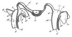
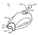
도 1a는 본 발명의 다른 실시형태에 의한 대체 입술 리트렉팅 장치를 개략적으로 나타낸 사시도이다.1A is a perspective view schematically showing an alternative lip retracting apparatus according to another embodiment of the present invention.
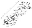
도 2는 출력 포트, 라이트 가이드, 이미징 장치, 라이트 소스 또는 검사 콘 등의 장치 내부에 끼워지는 도 1a에 도시된 입술 리트렉팅 장치를 개략적으로 나타낸 저면도이다.FIG. 2 is a bottom view schematically showing the lip retracting device shown in FIG. 1A fitted inside a device such as an output port, light guide, imaging device, light source or inspection cone.
도 3은 도 1에 도시된 입술 리트렉팅 장치를 개략적으로 나타낸 저면도이다.FIG. 3 is a bottom view schematically showing the lip retracting device shown in FIG. 1.
도 4는 도 3의 선 A-A를 따라 취해진 도 1에 도시된 입술 리트렉팅 장치를 개략적으로 나타낸 측면도이다.4 is a side view schematically showing the lip retracting device shown in FIG. 1 taken along line A-A of FIG.
도 5는 도 1에 도시된 입술 리트렉팅 장치를 개략적으로 나타낸 상면도이다.FIG. 5 is a top view schematically illustrating the lip retracting device illustrated in FIG. 1.
도 6은 도 4의 선 B-B를 따라 취해진 도 4에 도시된 입술 리트렉팅 장치를 개략적으로 나타낸 측면도이다.FIG. 6 is a schematic side view of the lip retracting device shown in FIG. 4 taken along line B-B in FIG. 4.
도 7은 도 5의 선 C-C를 따라 취해진 도 5에 도시된 입술 리트렉팅 장치를 개략적으로 나타낸 측면도이다.FIG. 7 is a schematic side view of the lip retracting device shown in FIG. 5 taken along line C-C of FIG. 5.
도 8은 본 발명의 다른 실시형태에 의한 대체 입술 리트렉팅 장치를 개략적으로 나타낸 사시도이다.8 is a perspective view schematically showing an alternative lip retracting apparatus according to another embodiment of the present invention.
도 9는 도 8에 도시된 입술 리트렉팅 장치를 유저/피검자가 착용한 상태를 나타낸 정면도이다.FIG. 9 is a front view illustrating a state where a user / testee wears the lip retracting device illustrated in FIG. 8.
도 10은 도 8에 도시된 입술 리트렉팅 장치를 유저/피검자가 착용한 상태를 나타낸 정면도이다.FIG. 10 is a front view illustrating a state where a user / testee wears the lip retracting device illustrated in FIG. 8.
도 10a는 도 8에 도시된 입술 리트렉팅 장치의 다른 실시형태를 유저/피검자가 사용하고 있는 상태를 나타낸 정면도이다.FIG. 10A is a front view showing a state where a user / testee is using another embodiment of the lip retracting device shown in FIG. 8. FIG.
도 11은 도 1a에 도시된 입술 리트렉팅 장치를 개략적으로 나타낸 상면도이다.FIG. 11 is a top view schematically illustrating the lip retracting apparatus shown in FIG. 1A.
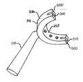
도 11a는 도 11에 도시된 입술 리트렉팅 장치를 더욱 상세히 개략적으로 나타낸 상면도이다.FIG. 11A is a top view schematically illustrating the lip retracting device illustrated in FIG. 11 in more detail.
도 11b는 라이트 가이드 속에 끼워지는 도 11a에 도시된 입술 리트렉팅 장치를 개략적으로 나타낸 저면도이다.FIG. 11B is a bottom view schematically showing the lip retracting device shown in FIG. 11A fitted into a light guide. FIG.
도 11c는 본 발명의 실시형태에 의한 라이트 가이드를 나타낸 도면이다.It is a figure which shows the light guide by embodiment of this invention.
도 12는 도 11에 도시된 입술 리트렉팅 장치를 개략적으로 나타낸 측면도이다.FIG. 12 is a side view schematically showing the lip retracting device shown in FIG. 11.
도 13은 슬롯을 가진 라이트 가이드를 개략적으로 나타낸 정면도이다.13 is a schematic front view of a light guide with slots.
도 14는 패드가 끼워진 도 11에 도시된 입술 리트렉팅 장치를 개략적으로 나타낸 측면도이다.FIG. 14 is a side view schematically showing the lip retracting device shown in FIG. 11 with the pads fitted; FIG.
도 15는 조개형 구조를 갖는 패드를 개략적으로 나타낸 상면도이다.15 is a schematic top view of a pad having a clam structure.
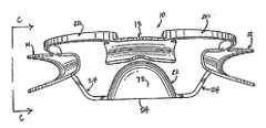
도 16은 U자형 채널을 포함하는 입술 리트렉팅 장치의 실시형태를 나타내는 사시도이다.16 is a perspective view illustrating an embodiment of a lip retracting device that includes a U-shaped channel.
도 16a는 도 16에 도시된 실시형태의 배면도이다.FIG. 16A is a rear view of the embodiment shown in FIG. 16. FIG.
도 17은 U자형 채널을 포함하는 입술 리트렉팅 장치의 실시형태를 나타내는 사시도이다.17 is a perspective view showing an embodiment of a lip retracting device including a U-shaped channel.
도 18은 탭을 가진 U자형 채널을 구비한 입술 리트렉팅 장치의 실시형태를 나타내는 사시도이다.18 is a perspective view illustrating an embodiment of a lip retracting device with a U-shaped channel with tabs.
도 19는 본 발명의 제 1 실시형태에 의한 하방 치아 세트와 상방 치아 세트 모두를 수용하는 입술 리트렉팅 장치를 나타낸 사시도이다.Fig. 19 is a perspective view showing a lip retracting device for accommodating both the lower tooth set and the upper tooth set according to the first embodiment of the present invention.
도 20은 라이트 가이드 및 램프를 가진 입술 리트렉팅 장치의 조합을 나타내는 분해도이다.20 is an exploded view showing a combination of a lip retracting device with a light guide and a lamp.
도 21은 본 발명의 실시형태와 함께 사용하기에 적합한 치과용 조명 시스템을 나타낸 사시도이다.21 is a perspective view of a dental lighting system suitable for use with an embodiment of the present invention.
도 22는 치과용 조명 시스템의 램프 헤드를 나타낸 사시도이다.22 is a perspective view of a lamp head of a dental lighting system.
도 23은 본 발명의 원리에 따른 라이트 가이드와 결합되는 도 16에 도시된 입술 리트렉팅 장치를 나타낸 상면도이다.FIG. 23 is a top view of the lip retracting device shown in FIG. 16 coupled with a light guide in accordance with the principles of the present invention.
도 24는 본 발명의 치과용 조명 시스템의 치과용 조명 프레임을 나타낸 사시도이다.24 is a perspective view of a dental lighting frame of the dental lighting system of the present invention.
도 25는 본 발명의 제 1 실시형태에 의한 유연한 쿠션 및 조명 프레임을 포함하는 라이트 가이드를 나타낸 분해사시도이다.25 is an exploded perspective view showing a light guide including a flexible cushion and an illumination frame according to the first embodiment of the present invention.
도 25a는 히트 싱크를 포함하는 조명 프레임의 실시형태를 나타낸 도면이다.25A illustrates an embodiment of an illumination frame that includes a heat sink.
도 26은 본 발명의 조명 프레임의 실시형태를 나타낸 사시도이다.It is a perspective view which shows embodiment of the illumination frame of this invention.
도 27은 본 발명의 제 1 실시형태에 의한 치과용 미백 또는 치료 램프를 나타낸 사시도이다.Fig. 27 is a perspective view showing a dental whitening or treatment lamp according to the first embodiment of the present invention.
도 28은 본 발명의 제 1 실시형태에 의한 입술 리트렉팅 장치와 결합되는 조명 프레이을 나타낸 상면도이다.It is a top view which shows the illumination frame couple | bonded with the lip retracting apparatus which concerns on 1st Embodiment of this invention.
도 28a는 본 발명의 실시형태에 의한 포메이션을 가진 조명 프레임을 나타낸 도면이다.FIG. 28A is a view showing an illumination frame with formation according to the embodiment of the present invention. FIG.
도 28b는 본 발명의 제 1 실시형태에 의한 입술 리트렉팅 장치와 결합되는 조명 프레임의 다른 실시형태를 나타낸 도면이다.FIG. 28B is a diagram showing another embodiment of the illumination frame combined with the lip retracting device according to the first embodiment of the present invention. FIG.
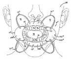
도 28c는 본 발명의 제 1 실시형태에 의한 피검자/유저에 결합된 예시적 입술 리트렉팅 장치를 개략적으로 나타낸 정면도이다.28C is a schematic front view of an exemplary lip retracting device coupled to a subject / user in accordance with a first embodiment of the present invention.
도 29는 본 발명의 실시형태에 의한 확장된 날개를 가진 리트렉팅 장치를 나타낸 사시도이다.29 is a perspective view showing a retracting device having an extended blade according to an embodiment of the present invention.
도 29a는 본 발명의 제 1 실시형태에 의한 타겟을 포함하는 리트렉팅 장치를 나타낸 사시도이다.It is a perspective view which shows the retracting apparatus containing the target by 1st embodiment of this invention.
도 29b는 본 발명의 실시형태에 의한 확장된 날개와 타겟을 가진 리트렉팅 장치를 나타낸 사시도이다.29B is a perspective view of a retracting device having an expanded wing and a target according to an embodiment of the present invention.
도 29c는 본 발명의 실시형태에 의한 필름 홀더를 포함하는 리트렉팅 장치를 나타낸 사시도이다.It is a perspective view which shows the retracting apparatus containing the film holder by embodiment of this invention.
도 29d는 리트렉팅 장치의 대체 구조를 나타낸 사시도이다.29D is a perspective view showing an alternative structure of the retracting device.
도 29e는 리트렉팅 장치의 다른 실시형태를 나타낸 사시도이다.29E is a perspective view showing another embodiment of the retracting device.
도 30은 본 발명의 제 1 실시형태에 의한 정적 이미징 스탠드를 나타낸 사시도이다.30 is a perspective view showing a static imaging stand according to the first embodiment of the present invention.
도 30a는 치과용 지지 구조 및 치과용 이미징 픽스쳐링 시스템(imaging fixturing system)을 포함하는 본 발명의 실시형태를 나타낸 도면이다.30A illustrates an embodiment of the present invention that includes a dental support structure and a dental imaging fixturing system.
도 30b는 치과용 지지 구조 및 치과용 이미징 픽스쳐링 시스템을 포함하는 본 발명의 다른 실시형태를 나타낸 도면이다.30B illustrates another embodiment of the present invention that includes a dental support structure and a dental imaging fixture system.
첨부 도면과 결합된 이하의 상세한 설명은 본 발명에 따라 제공된 리트렉팅 장치의 현재의 예시적인 실시형태의 명세서로서 의도된 것이고, 본 발명이 구성 또는 사용될 수 있는 유일한 형태를 표현하고자 하는 것은 아니다. 본 명세서는 예시된 실시형태와 관련하여 본 발명의 리트렉팅 장치를 구성 및 사용하기 위한 스텝 및 특징을 설명한다. 그러나, 본 발명의 사상 및 범위 내로 포함되는 것으로 의도되는 다른 실시형태에 의해 동일하거나 동등한 기능 및 구조가 달성될 수도 있다는 것이 이해될 것이다. 또한, 여기 어딘가에 나타낸 바와 같이, 비슷한 구성요소 번호는 비슷하거나 유사한 구성요소 또는 특징을 나타내려는 것이다.The following detailed description in conjunction with the accompanying drawings is intended as a specification of the present exemplary embodiments of the retracting device provided in accordance with the present invention, and is not intended to represent the only form in which the present invention may be constructed or used. This specification describes steps and features for constructing and using the retracting apparatus of the present invention in connection with the illustrated embodiment. However, it will be understood that the same or equivalent functions and structures may be achieved by other embodiments that are intended to be included within the spirit and scope of the invention. Also, as indicated elsewhere herein, like element numbers are intended to indicate like or similar elements or features.
리트렉팅 장치는 상호-맞물림 및/또는 비-상호-맞물림 포메이션을 포함한다. 상호-맞물림 포메이션은 장치, 기구, 도구를 다른 장치, 기구, 도구에 있어서의 하나 이상의 대응 포메이션과 맞물리게 하는 포메이션을 포함한다. 비-상호-맞물림 포메이션은 이러한 장치, 기구, 또는 도구를 적어도 피검자의 입 부분에 근접하게 하는 포메이션을 포함한다.The retracting device includes inter-engagement and / or non-inter-engagement formations. Inter-engagement formations include formations that engage a device, instrument, or tool with one or more corresponding formations in another device, instrument, or tool. Non-inter-engagement formations include formations that bring such an apparatus, instrument, or tool at least close to the mouth of the subject.
라이트 시스템, 라이트 가이드, 이미징 시스템, 치과용 치료 구조물, 이미징 시스템, 흡인용으로 된 장치, 리트렉팅 장치, 스페이서, 지지 시스템, 또는 흡인기나 흡입 튜브와 같은 흡인용으로 된 치과용 기구 등의 치과용 시스템과 관련되어 여기에 사용된 워드 포메이션(word formation)은 인접한 치과용 시스템, 치과용 구조물, 또는 피검자의 입의 대응 부분과 상호-끼워지도록 된 치과용 시스템의 부분을 나타낸다. 따라서 포메이션은 적어도 상기 모든 항목의 일부를 포함하고, 성형에 의해 형성 또는 구체화될 수 있고, 또는, 상기 포메이션이 개별적으로 형성된 후에 이어서 각각의 항목과 함께 조립될 수 있다.Dentistry such as light systems, light guides, imaging systems, dental treatment structures, imaging systems, suction devices, retracting devices, spacers, support systems, or dental instruments such as suction devices or suction tubes such as suction devices The word formation used herein in connection with a dental system refers to that portion of the dental system that is intended to inter-engage with an adjacent dental system, dental structure, or a corresponding portion of the subject's mouth. The formation may thus comprise at least part of all of the above items and may be formed or embodied by molding, or may be assembled together with each item after the formation is formed separately.
적절한 상호-맞물림 포메이션은 혀와 홈, 포스트와 소켓, 스윙 가능한 후크와 소켓, 탄성 클립과 소켓, 클립과 돌출부 또는 클립과 오목부, 혀 또는 날개형 부재와 슬롯, 볼과 캐버티, 볼과 소켓을 포함하고, 특히, 이 중에서 일부는 이하 상세히 설명된다. 비-상호-맞물림 포메이션은 덴탈 트레이, 이미징 필름 홀더, 및 모든 덴탈 치료나 이미징 머티리얼을 피검자의 입 내에 위치결정하도록 된 다른 기구를 포함한다.Suitable inter-engagement formations include tongues and grooves, posts and sockets, swingable hooks and sockets, elastic clips and sockets, clips and protrusions or clips and recesses, tongue or wing members and slots, balls and cavities, balls and sockets In particular, some of these are described in detail below. Non-interlocking formations include dental trays, imaging film holders, and other instruments adapted to position all dental treatments or imaging materials within the subject's mouth.
도 1을 참조하면, 본 발명의 제 1 실시형태에 의해 제공된 입 및/또는 치아의 검사 및/또는 치료를 용이하게 하기 위한 윗입술 및 아랫입술(여기서는 "입술")을 리트렉팅하는 입술 리트렉팅 장치가 일반적으로 도시되어 있고, 부호 10으로 표시된다. 혀컵(tongur cup)으로도 알려진 입술 리트렉팅 장치(10)는 플랜지로 알려진 4개의 이격된 채널 리테이너(12, 14, 16, 18)를 포함하고, 이 4개의 채널 리테이너는 입 또는 치아의 검사 및/또는 치료를 위해 입술의 4개의 대응 부분을 리트 렉팅하기 위한 것이다. 사용시에 있어서, 도 9 및 도 10에 도시된 바와 같이, 입술 리트렉팅 장치(10)가 입술을 당겨서 양볼을 리트렉팅하여 입을 노출시킴으로써 건강관리 전문가는 치아를 더 쉽게 관찰하면서 치아 및/또는 입에 작업을 할 수 있게 된다.Referring to FIG. 1, a lip retreat retracting the upper and lower lip (here “lip”) to facilitate the examination and / or treatment of the mouth and / or teeth provided by the first embodiment of the present invention. The device is generally shown and indicated by
4개의 채널 리테이너는 윗입술과 아랫입술이 실질적으로 교차하는 입술의 단부를 리트렉팅하기 위한 두개의 사이드 채널 리테이너(12, 14), 및 윗입술과 아랫입술의 중간부분을 리트렉팅하기 위한 두개의 입술 채널 리테이너(16, 18)를 포함한다. 더욱 상세하게는, 4개의 채널 리테이너 또는 플랜지(12, 14, 16, 18)는 상기한 바와 같이 치료 및/또는 검사를 위해 도 9 및 도 10에 예시된 바와 같이 입술을 받치고, 개방된 입술을 바이어싱하여 치아를 노출시킨다.The four channel retainers include two side channel retainers (12, 14) for retracting the ends of the lips where the upper and lower lips substantially intersect, and two for retracting the middle of the upper and lower lip.
복수의 탄성 부재(20)는 4개의 채널 리테이너(12, 14, 16, 18)를 서로 결합하고, 바이어싱 수단으로서 기능하기 위해 입술 리트렉팅 장치(10)에 일체화된다. 준비 위치(입 속으로 입술 리트렉팅 장치를 삽입하기 전)에 있어서, 탄성 부재(20)는 리트렉팅 장치(10)의 중앙부에 대해 외측으로 아치형태가 된다. 이하 더 논의되는 바와 같이, 리트렉팅 장치(10)는 입 속으로 삽입되고, 4개의 채널 리테이너(12, 14, 16, 18)는 입술 부분을 각각 받치고, 탄성 부재(20)는 검사 및/또는 치료를 위해 입술을 외측 방사상으로 리트렉팅하는 리트렉팅력을 제공한다.The plurality of
임의의 혀 리테이너(22)는 4개의 채널 리테이너(12, 14, 16, 18)에 대하여 실질적으로 중앙에 위치결정된다. 혀 리테이너는 두개의 채널 리테이너(16, 18)에 대하여 비대칭적으로 위치결정될 수도 있다. 혀 리테이너(22)는 트러 프(trough)(23)를 포함하고, 한 쌍의 제 2 탄성 부재(24)에 의해 두개의 채널 리테이너(12, 14)에 부착된다. 합체시에, 혀 리테이너(22)와 제 2 탄성 부재(24)는 협력하여 혀를 차단하고, 입의 뒷쪽 부근으로 혀를 제한함으로써 검사 및/또는 치료를 위해 치아의 설음 부분이나 뒷부분에 접근 가능하게 한다. 요컨대, 혀 리테이너는 건강관리 전문가에 의한 치료 및/또는 검사 중에 혀에 의한 방해를 최소화하도록 구성된다.Any
모든 탄성 부재(20)는 단일 조각으로 형성되어 접착제 또는 히트 실링에 의해 예컨대, 한쌍의 인접한 채널 리테이너(14, 16)의 외측면(28b, 44b)에 일체로 성형 또는 부착되거나, 갈라진 두개의 절반으로 형성되고 중앙부에 결합되어 인접 채널 리테이너(14, 16)의 외측면(28b, 44b)에 접착제 또는 히트 실링에 의해 일체로 성형 또는 부착될 수 있다.All
도시된 바와 같이, 사이드 채널 리테이너(12, 14)는 아치형 레이스(26) 및 두개의 채널 측벽(28a, 28b)을 포함하는 곡선형 c-채널과 유사하다. 채널 측벽(28a, 28b)은 벨 형상과 유사하고, 실질적으로 중간점(34)에서의 최대 벽 치수와 그 단부에서의 두개의 더 작은 테이퍼진 팁(36)을 포함한다. 제 1 실시형태에 있어서, 상세히 후술되는 바와 같이 입 내부에 위치결정되는 내측벽(28a)은 외측벽(28b)에 비해 약간 크다. 그러나, 리트렉팅 장치(10)의 기능성으로부터의 벗어남 없이 상대 치수가 반대가 되거나 동일하게 될 수 있다.As shown, the
사이드 채널 리테이너(12, 14)는 내면(30)과 외면(32)을 더 포함한다. 아치형 레이스(26)는 입술이 개방 위치에 있는 경우에 입술 측면의 굴곡과 흡사하게 된 굴곡부(31)를 포함한다. 이 굴곡은 유저나 피검자의 사이즈와 나이에 의거하여 변경될 수 있기 때문에, 리트렉팅 장치(10)는 특정 유저/피검자의 변경된 형상에 맞추기 위해 굴곡부(31)의 반경을 변경하여 실행될 수 있다. 아치형 레이스(26)는 불규칙한 굴곡 또는 둘 이상의 상이한 굴곡 반경을 포함할 수도 있다. 예컨대, 굴곡부(31)의 하부 영역(38)은 상부 영역(40)보다 큰 반경을 갖거나 그 반대가 될 수 있다. 실행되면, 불규칙한 굴곡은 입술 부분 사이의 리트렉팅량을 변경하기 위해 아치형 레이스 내에 안착된 입술 부분의 리트렉팅량을 변경할 수 있다. 두개의 입술 채널 리테이너(16, 18)도 사이드 채널 리테이너(12, 14)와 유사하게 상이한 굴곡 반경을 가질 수 있다.The
도시된 바와 같이, 입술 채널 리테이너(16, 18)는 사이드 채널 리테이너(12, 14)와 마찬가지로, 아치형 레이스(42)와 두개의 채널 측벽(44a, 44b)을 포함하는 곡선형 c-채널과 유사한다. 제 1 실시형태에 있어서, 입술 채널 리테이너의 굴곡 부(46)의 반경은 사이드 채널 리테이너(12, 14)의 굴곡부(31)의 반경보다 크다. 굴곡부(46)의 큰 반경은 입술 채널 리테이너(16, 18)가 입술의 측면에 비해 더 평평한 프리넘(frenum) 근방의 아랫입술과 윗입술의 윤곽과 같은 모양이 되게 한다. 예정된 유저/피검자의 사이즈 및 나이에 의거하여 입술 채널 리테이너(16, 18)의 굴곡부(46)의 반경이 변경될 수도 있다.As shown, the
도시된 바와 같이, 프리넘 릴리즈(48)는 윗입술과 아랫입술의 프리넘에 휴식을 제공하기 위한 입술 채널 리테이너(16, 18)의 내측벽(44a) 내에 일체화된다. 제 1 실시형태에 있어서, 프리넘 릴리즈(48)은 프리넘을 위한 여유공간을 제공하기에 충분한 사이즈를 가진 부분적 타원형 컷아웃을 포함한다. 즉, 프리넘 릴리즈(48)는 예컨대, 사용시에 프리넘 릴리즈의 최저부(50)가 프리넘에 약간만 접촉하거나, 프리넘에 접촉하지 않게 될 수 있다. 타원형 컷아웃이 프리넘 릴리즈(48)를 위한 것으로 도시되어 있지만, 부분적 원형, 직사각형 컷아웃, 정사각형 컷아웃, 또는 다른 기하학적 형태의 컷아웃도 프리넘 릴리즈의 기능으로부터 벗어남 없이 일체화될 수 있다.As shown, the
현재 부호 10으로 표시된 입술 리트렉팅 장치는 폴리프로필렌, 폴리에틸렌, 폴리스티렌, 폴리에스테르, 폴리카보네이트 등의 열가소성 물질을 사출성형 또는 캐스팅함으로써 만들어질 수 있다. 입술 리트렉팅 장치는 폴리락트산 수지(L-락트산과 D-락트산을 가짐)와 폴리글리콜산(PGA) 등의 폴리에스테르; 폴리히드록시발레레이트/히드록시부티레이트 수지(PHBV)[ 3-히드록시 부티르산과 3-히드록시 펜탄산(3-히드록시 발레르산)의 공중합체]와 폴리히드록시알카노에이트(PHA) 공중합체; 및 폴리에스테르/우레탄 수지를 포함하는 생화합성 또는 생분해성 폴리머에 의해 만들어질 수도 있다. 예컨대, 입술 리트렉팅 장치는 폴리프로필렌을 사출성형하여 만들어질 수 있고, 부드럽고 투명하게 마무리될 수 있다. 다른 실시형태에 있어서, 상기 장치는 흰색을 포함하여 착색되고, 불투명하게 될 수 있다.The lip retracting device, currently indicated by the
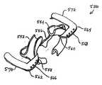
도 1b에 도시된 바와 같이, 두개의 포메이션 예컨대, 두개의 날개형 플랜지(100)는 도 1의 입술 리트렉팅 장치에 일체화될 수 있다. 이 날개형 플랜지(100)는 사이드 채널 플랜지 또는 리테이너(12, 14)에 접착제에 의해 부착되거나 일체로 성형 또는 캐스팅될 수 있고, 상기 물질을 포함하는 채널 프랜지 또는 리테이너나 리트렉팅 장치의 다른 부분과 동일하거나 상이한 물질, 또는 더욱 튼튼한 중합물질이나 합성물로 구성될 수 있다. 또한, 입술 리트렉팅 장치의 나머지가 착색되지 않거나 깨끗하더라도 불투명하거나 착색될 수도 있다. 날개형 플랜지(100)는 출력 포트, 이미징 장치, 램프 시스템, 또는 미백 처리에 사용되는 램프 시스템(1102)의 라이트 가이드 내에 형성된 슬롯(1130, 1132)과 같은 한 쌍의 포메이션, 또는 입술 리트렉팅 장치(1138), 라이트 가이드(1120), 및 램프 시스템(1102)의 조합의 분해도인 도 20의 예시적 조명 시스템 내에 도시된 바와 같은 모든 검사 장치 내의 슬롯 속으로 끼워지게 디자인될 수 있다. 다른 예시적 조명 시스템이나 램프 시스템의 사용은 전체를 설명하는 것처럼 참조에 의해 여기에 명백하게 포함된 Ser. No. 10/715,681(2003년 11월 17일에 출원됨)에 개시되어 있다.As shown in FIG. 1B, two formations, eg, two
다른 실시형태에 있어서, 도 20에 도시된 바와 같은 라이트 가이드(1120)를 대신하여 상기 콘형 구조와 같은 검사 장치는 도 13에 도시된 바와 같이, 램프(104)의 아웃렛과 입술 리트렉팅 장치(1138) 상의 날개형 플랜지(100) 위에 끼워지도록 구성될 수 있다. 날개형 플랜지(100)는 상기 콘 상의 슬롯(112)과 같은 포메이션과 상호작용하여 치료되거나 검사될 피검자의 치아와 램프(104) 사이의 안정되고 제어된 갭을 제공하도록 구성될 수 있다.In another embodiment, the inspection device, such as the cone-shaped structure, in place of the
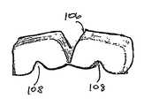
이제 도 1a를 참조하면, 검사, 입 및/또는 치아의 이미징, 및/또는 미백 또는 치료 처리를 용이하게 하기 위해 입술을 리트렉팅하는 본 발명의 제 1 실시형태에 의한 입술 리트렉팅 장치(10')가 도시되어 있다. 상기 리트렉팅 장치는 입 및/또는 치아의 검사 및/또는 치료를 위해 입술의 두 대응 부분을 리트렉팅하는 두개 의 이격된 채널 리테이너 또는 플랜지(12', 14')를 포함한다. 사용시에 있어서, 입술 리트렉팅 장치(10')는 입을 노출시키기 위해 양볼을 리트렉팅하는 입술을 마찬가지로 뒤로 당겨서 건강관리 전문가가 치아를 더욱 용이하게 관찰하고, 치아 및/또는 입에 작업할 수 있게 한다.Referring now to FIG. 1A, a lip retracting device according to a first embodiment of the present invention for retracting the lips to facilitate examination, imaging of the mouth and / or teeth, and / or whitening or therapeutic treatment ( 10 ') is shown. The retracting device comprises two spaced channel retainers or flanges 12 ', 14' for retracting two corresponding portions of the lips for examination and / or treatment of the mouth and / or teeth. In use, the lip retracting device 10 'likewise pulls back the lips retracting the cheeks to expose the mouth so that health care professionals can more easily observe the teeth and work on the teeth and / or the mouth. To be.
도 1 및 도 1a의 리트렉팅 장치와 마찬가지로, 두개의 채널 리테이너(12', 14')는 윗입술과 아랫입술이 실질적으로 교차하는 입술의 단부를 리트렉팅하도록 될 수 있다. 특히, 두개의 채널 리테이너 또는 플랜지(12', 14')는 입술을 받치고, 열린 입술을 바이어싱하도록 되어 치료 및/또는 검사를 위해 치아를 노출시킨다.Like the retracting device of FIGS. 1 and 1A, the two
탄성 부재(20')는 입술 리트렉팅 장치(10')에 일체화되어 두개의 채널 리테이너(12', 14')와 함께 결합되고, 바이어싱 수단으로서 기능한다. 탄성 부재(20')는 예컨대, 도시된 바와 같이 두개의 아치를 구비하고, 각각은 중앙부(22')의 양측 상에 위치한다. 탄성 부재(20')는 단일 피스로서 채널 리테이너(12', 14')의 내측벽(28a')에 접착제 또는 히트 실링에 의해 일체로 성형 또는 부착되거나, 갈라진 두개의 절반으로 형성되고 중앙부(22')에 결합되어 채널 리테이너(12', 14')의 내측벽(28a')에 접착제 또는 히트 실링에 의해 일체로 성형 또는 부착될 수도 있다. 준비 위치(입술 리트렉팅 장치를 입 속으로 삽입하기 전)에 있어서, 탄성 부재(20')는 입술 리트렉팅 장치(10')의 중앙부에 대해 외측으로 아치형태가 될 수 있다. 이하 더 논의되는 바와 같이, 입술 리트렉팅 장치(10')가 입 속에 삽입되고, 두개의 채널 리테이너(12', 14')가 입술 부분을 각각 받치는 경우에, 탄성 부재(20')는 검사 및/또는 치료를 위해 입술을 외측 방사상으로 리트렉팅하는 리트렉 팅력을 제공한다. 입술 리트렉팅 장치는 특히 미백 처리에 유용하다.The elastic member 20 'is integrated with the lip retracting device 10' and is coupled with two channel retainers 12 ', 14' and functions as a biasing means. The elastic member 20 ', for example, has two arches as shown, each located on both sides of the central portion 22'. The elastic member 20'is formed as a single piece, integrally molded or attached to the
임의의 혀 리테이너(22')는 두개의 채널 리테이너(12', 14')에 대하여 실질적으로 중앙에 위치결정될 수도 있다. 도 1의 혀 리테이너(22)와 마찬가지로, 본 실시형태에 의한 혀 리테이너(22')도 트러프(23')를 포함할 수 있다. 또한, 탄성 부재(20')의 중앙부 상에 일체로 형성됨으로써 탄성 부재(20')를 통해 채널 리테이너(12', 14')에 부착될 수 있다. 합체시에, 상기 논의된 바와 마찬가지로, 혀 리테이너도 혀를 차단하고, 입의 뒷쪽 부근으로 혀를 제한함으로써 검사 및/또는 치료를 위해 치아의 설음 부분이나 뒷부분에 접근 가능하게 하여 건강관리 전문가에 의한 치료 및/또는 검사 중에 혀에 의한 방해를 최소화한다.Any tongue retainer 22 'may be positioned substantially centrally relative to the two channel retainers 12', 14 '. Similar to the
본 실시형태에 있어서, 탄성 부재(20')는 채널 리테이너를 결합하여 바이어싱하는 것뿐만 아니라 채널 리테이너에 혀 리테이너를 결합하는 작용을 한다. 혀 리테이너(22')가 일체화되지 않으면, 탄성 부재(20')는 하나의 채널 리테이너(12')로부터 다른 채널 리테이너(14')로 실질적으로 일정한 폭으로 간단히 확장된다.In this embodiment, the elastic member 20 'acts to engage and retain the channel retainer as well as to engage the tongue retainer with the channel retainer. If tongue retainer 22 'is not integrated, elastic member 20' simply extends substantially constant width from one channel retainer 12 'to another channel retainer 14'.
채널 리테이너(12', 14')도 아치형 레이스(26') 및 두개의 채널 측벽(28a', 28b')을 포함하는 곡선형 c-채널과 유사하다. 채널 측벽(28a', 28b')도 벨 형상과 유사하고, 실질적으로 중간점(34')에서의 최대 벽 치수와 그 단부에서의 두개의 더 작은 테이퍼진 팁(36')을 포함한다. 제 1 실시형태에 있어서, 입 내부에 위치결정되는 내측벽(28a')은 외측벽(28b')에 비해 약간 클 수 있다. 그러나, 입술 리트렉팅 장치(10')의 기능성으로부터의 벗어남 없이 상대 치수가 다시 반대가 되거나 동일하게 될 수 있다.Channel retainers 12 ', 14' are also similar to curved c-channels comprising an arcuate lace 26 'and two
도 1 및 도 1b와 마찬가지로, 사이드 채널 리테이너(12', 14')는 내면(30')과 외면(32')을 더 포함한다. 아치형 레이스(26')는 입술이 개방 위치에 있는 경우에 입술 측면의 굴곡과 흡사하게 된 굴곡부(31')의 반경을 포함한다. 또한, 이 굴곡은 유저나 피검자의 사이즈와 나이에 의거하여 변경될 수 있기 때문에, 상기한 바와 같이, 입술 리트렉팅 장치(10')는 특정 유저/피검자의 변경된 형상에 맞추기 위해 굴곡부(31')의 반경을 변경하여 실행될 수 있다. 아치형 레이스(26')는 불규칙한 굴곡 또는 둘 이상의 상이한 굴곡 반경을 포함할 수도 있다. 예컨대, 굴곡부(31')의 하부 영역(38')은 상부 영역(40')보다 큰 반경을 갖거나 그 반대가 될 수 있다. 실행되면, 불규칙한 굴곡은 입술 부분 사이의 리트렉팅량을 변경하기 위해 아치형 레이스 내에 안착된 입술 부분의 리트렉팅량을 변경할 수 있다.Like the FIGS. 1 and 1B, the
마찬가지로, 입술 리트렉팅 장치(10')도 상기한 바와 같은 열경화성 물질을 사출성형 또는 캐스팅함으로써 만들어질 수 있다. 예컨대, 입술 리트렉팅 장치(10')는 착색된 폴리프로필렌을 사출성형함으로써 만들어질 수 있고, 부드러운 마무리를 가진 불투명한 백색이나 다른 색으로 착색되거나, 깨끗한 폴리프로필렌을 사출성형함으로써 부드러운 마무리를 가지고 만들어질 수 있다.Likewise, the lip retracting device 10 'can also be made by injection molding or casting a thermosetting material as described above. For example, the lip retracting device 10 'can be made by injection molding colored polypropylene, colored with opaque white or other color with a smooth finish, or with a soft finish by injection molding clean polypropylene. Can be made.
또한, 도 1a도 채널 리테이너(12', 14')의 외측벽(28b')으로부터 확장된 날개형 플랜지(100)와 같은 두개의 포메이션을 나타낸다. 날개형 플랜지(100)도 상기한 바와 같이, 채널 플랜지 또는 리테이너(12', 14')와 일체로 성형 또는 캐스팅되거나 부착될 수 있다. 이미 더 논의되고, 상세히 후술하는 바와 같이, 날개형 플랜지는 출력 포트의 콘 부분, 또는 치아 미백, 치료 또는 이미징 처리에 사용되는 램 프 소스의 라이트 가이드 상에 형성되는 슬롯과 같은 포메이션에, 또는 모든 검사 장치의 슬롯에 입술 리트렉팅 장치(10')를 끼우기 위해 디자인될 수 있다. 예시된 바와 같이 도 2는 예컨대, 점선으로 도시된 램프(104)에 부착된 라이트 가이드(102) 상의 슬롯과 맞물린 날개형 플랜지(100)를 가진 입술 리트렉팅 장치(10')의 저면도이다.FIG. 1A also shows two formations, such as the
상기한 바와 마찬가지로, 날개형 부재 또는 플랜지(100)는 입술 리트렉팅 장치의 나머지 또는 상기 물질을 포함하는 채널 플랜지 또는 리테이너와 동일하거나 상이한 물질로, 또는 더 튼튼한 중합물질이나 합성물로 만들어질 수 있다. 또한, 입술 리트렉팅 장치의 나머지가 무색이거나 깨끗하더라도 불투명하게 되거나 착색될 수도 있다.As noted above, the winged member or
도 3은 도 1의 입술 리트렉팅 장치(10)를 개략적으로 나타낸 저면도이다. 입술 리트렉팅 장치(10)는 레디-투-유즈(ready-to-use) 구조로 도시되어 있고, 이 구조는 4개의 탄성 부재(20)가 4개의 채널 리테이너(12, 14, 16, 18)를 외측(52)으로 또는 다른 하나로부터 이격되게 바이어싱하는 구조이다. 마찬가지로, 두개의 제 2 탄성 부재(24)는 4개의 채널 리테이너(12, 14, 16, 18)의 위치를 결정하는 평면으로부터 멀리(관찰자를 향하여 실질적으로 수직으로) 혀 리테이너를 바이어싱한다. 따라서, 이하 더 논의되는 바와 같이, 서비스 중에 입술 리트렉팅 장치(10)가 입에 놓여지는 경우에, 도 9 및 도 10에 도시된 바와 같이, 4개의 채널 리테이너(12, 14, 16, 18)는 입술을 받치게 되고, 4개의 탄성 부재(20)가 탄성 부재(20)의 탄성에 의해 오픈된 입술을 확장하게 됨으로써 입술모양(labial) 또는 치아의 전면부를 노출시킨다. 마찬가지로, 혀 리테이너(22)는 혀를 차단하고, 두개의 제 2 탄성 부재(24)가 혀를 목구멍을 향하여 입의 뒷쪽 영역으로 제한하게 되어 도 9에 도시된 바와 같이, 상부 치아와 하부 치아의 뒷부분 또는 설음을 더 노출시키게 된다.3 is a bottom view schematically showing the
피검자의 입 속에 서비스를 하는 경우에, 도 4에 도시된 바와 같이, 외측벽(28b, 44b)과 4개의 탄성 부재(20)가 입 외부에 위치결정되도록 구성되는 반면, 내측벽(28a, 44a), 제 2 탄성 부재(24), 및 트러프(23)를 포함하는 혀 리테이너(22)는 입 내부에 위치결정되도록 구성된다. 4개의 탄성 부재(20)는 외측벽(28b, 44b)에 일체로 성형되어 입 속에 입술 리트렉팅 장치를 삽입하는 것을 방해하지 않게 된다.In the case of service in the mouth of a subject, as shown in FIG. 4, the outer walls 28b and 44b and the four
도 4는 도 3의 선 A-A에서 취해진 입술 리트렉팅 장치를 개략적으로 나타낸 측면도이다. 도 4는 상부 림(54)과 하부 림(56)을 포함하는 혀 리테이너(22)를 나타낸다. 상부 림(54)은 하부 림(56)에 비해 더 높게 위치결정되고(즉, 입술 리트렉팅 장치가 서비스될 때 하부 림보다 입 속으로 더 돌출됨), 두개의 제 2 탄성 부재(24)에 일체로 성형 또는 부착된다. 대안으로서, 혀 리테이너(22)는 두개의 림을 구비하여 혀의 상부면과 하부면을 따라 평평하게 혀를 유지할 수 있다.4 is a side view schematically showing the lip retracting device taken at line A-A of FIG. 4 shows a
두개의 제 2 탄성 부재(24)는 상부 림(54)으로부터 연장된 수평부(58), 및 상기 수평부(58)와 두개의 사이드 채널 리테이너(12, 14)의 굴곡부(31)에 결합된 경사부(60)를 구비하는 것으로 도시되어 있다. 대안으로서, 두개의 제 2 탄성 부재(24)는 상부 림과 굴곡부에 모두 결합된 하나의 경사부를 포함할 수 있다.Two second
특히, 우측 채널 리테이너(12)를 참조하면, 채널 리테이너를 레이스(26) 실 질적으로 중앙점에서 분할하는 채널 중심선(

탄성 부재(20)가 사이드 채널 리테이너(12, 14)의 외측면(28b)과 입술 채널 리테이너(16)의 외측면(44b)에 일체로 성형 또는 부착되는 방식이 도 4에 도시되어 있다. 특정 실시형태에 있어서, 탄성 부재(20)는 사이드 채널 리테이너(12, 14)의 내면(30)과 입술 채널 리테이너(16)의 내면(68)으로 흘러들어가고, 평평하고, 또는 그 반대로 부드럽게 변형되는 상부 에지(66)를 각각 구비한다. 이러한 배열은 입술 리트렉팅 장치(10)가 입술과 양볼의 내면에 대하여 돌출되거나 삐져나오는 날카로운 에지 없이 착용되게 한다. 그러나, 입술과 양볼이 유연하고, 유저/피검자의 지나친 불편함 없이 약간의 편향을 수용할 수 있기 때문에 상부 에지(66)와 채널 리테이너(12, 14, 16)의 내면(30, 68) 사이의 변형에 있어서의 약간의 편향은 여전히 받아들여질 수 있다.The manner in which the
이제 도 5를 참조하면, 도 1의 입술 리트렉팅 장치를 예시적으로 나타낸 개 략 평면도가 도시되어 있다. 도시된 바와 같이, 탄성 부재(20)의 종점(end point)(72)은 탄성 부재(20)와 채널 리테이너(12, 14, 16, 18) 사이의 일체적 결합 또는 성형을 위해 사이드 채널 리테이너(12, 14)의 에지(74)와 입술 채널 리테이너(16, 18)의 에지(76)를 지나 확장된다. 그러나, 종점(72)과 에지 사이의 오버랩 량은 실질적으로 또는 전혀 오버랩되지 않고 충분한 강도를 가질 수 있는 입술 리트렉팅 장치(10)를 성형하는데 사용되는 특정 물질에 따라 변경될 수 있다. 혀 리테이너(22)는 타원형 윤곽과 부드러운 외면(78)을 구비하는 것으로 도시되어 있다. 그러나, 원형, 정사각형, 직사각형, 또는 다른 기하학적 형상의 혀 리테이너(22)가 본 발명의 사상으로부터 벗어남 없이 사용될 수도 있다.Referring now to FIG. 5, there is shown a schematic plan view illustratively showing the lip retracting device of FIG. 1. As shown, the
도 6은 도 5의 선 B-B에서 취해진 입술 리트렉팅 장치를 개략적으로 나타낸 단면도이다. 도시된 바와 같이, 사이드 채널 리테이너(12, 14)와 입술 채널 리테이너(16, 18)가 곡면을 형성하는 것으로 가정하면, 이 곡면의 아래에 혀 리테이너(22)의 상부 림(54)이 있다. 앞에서 논의된 바와 같이, 밑에 있는 구조와 트러프(23)의 깊이(도 3)는 혀 리테이너(22)가 입의 뒤에 혀를 한정 및 유지하게 하여 치아의 설음면을 더 노출시킨다.FIG. 6 is a schematic cross-sectional view of the lip retracting device taken at line B-B in FIG. 5. As shown, assuming that the
도 7은 도 6의 선 C-C에서 취해진 입술 리트렉팅 장치를 개략적으로 나타낸 측면도이다. 도 4의 사이드 채널 리테이너(12)과 마찬가지로, 입술 채널 리테이너(18)는 입술 채널 리테이너를 아치형 레이스(42)의 실질적으로 중심선에서 분할하는 입술 채널 중심선(

대안으로서, 앞서 논의된 바와 같이, 사이드 채널 리테이너에 있어서, 중심선에 대하여 내측 및 외측벽(44a, 44b)의 모서리 부분이 동일하거나 반대로 되도록 특정 관계가 스위칭될 수 있다.Alternatively, as discussed above, in the side channel retainer, certain relationships may be switched such that the corner portions of the inner and
도 8은 본 발명의 다른 실시형태에 의해 제공된 대체 입술 리트렉팅 장치를 개략적으로 나타낸 사시도이다. 도시된 바와 같이, 입술 리트렉팅 장치는 두개의 사이드 채널 리테이너(12', 14'), 두개의 입술 채널 리테이너(16', 18'), 및 4개의 탄성 부재(20')를 포함한다. 제 1 실시형태에 있어서, 대체 입술 리트렉팅 장치(10')는 혀 리테이너를 포함하는 것을 제외하고, 도 1, 도 1b, 도 3 ~ 도 7의 입술 리트렉팅 장치(10)와 동일하다. 따라서, 입술 리트렉팅 장치(10)에 관한 상기 설명은 혀 리테이너를 제외한 대체 입술 리트렉팅 장치(10')에 적용된다.8 is a perspective view schematically showing an alternative lip retracting device provided by another embodiment of the present invention. As shown, the lip retracting device includes two side channel retainers 12 ', 14', two lip channel retainers 16 ', 18', and four elastic members 20 '. In the first embodiment, the replacement lip retracting device 10 'is the same as the
마찬가지로, 특별히 도시되지는 않았지만, 입술 리트렉팅 장치(10')도 도 1a에 도시된 바와 같이, 임의의 혀 리테이너 없이 만들어질 수 있다.Likewise, although not specifically shown, the
도 9는 도 1의 입술 리트렉팅 장치(10)를 피검자 또는 유저(84)가 사용하고 있는 예시적 상태를 개략적으로 나타낸 평면도이다. 도시된 바와 같이, 입술 리트렉팅 장치(10)는 유저의 입(86)과 맞물려서 유저의 입술(88)과 양볼(90)을 리트렉팅한다. 이 상태에서, 유저의 입(86)과 특히 치아(92)는 건강관리 전문가에 의한 검사 및/또는 치료를 위해 노출된다. 더욱 상세하게는, 사이드 채널 리테이너(12, 14)는 입의 측면과 맞물리고, 입술 채널 리테이너(16, 18)는 윗입술 및 아랫입술(88)과 맞물리고, 탄성 부재(20)는 오픈된 입술(88)과 양볼(90)을 바이어싱하는 4개의 채널 리테이너를 바이어싱하여, 치아와 입(86) 내부를 노출시킨다. 입술 리트렉팅 장치가 착용된 상태에서, 외측면(28b, 44b)과 탄성 부재(20)는 입의 외측으로 노출된다.FIG. 9 is a plan view schematically illustrating an exemplary state in which a subject or a
혀 리테이너(22)는 혀(94)와 맞물려 도시되어 있고, 입(86)의 뒷쪽 영역으로 혀를 후퇴시킨다. 일체화되는 경우에, 혀 리테이너(22)는 검사 및/또는 치료를 위해 치아의 설음면(96)을 더 노출시키도록 구성된다.
입술 리트렉팅 장치(10)는 우선 윗입술을 내측벽(44a)에 걸쳐 윗입술 채널 리테이너(16)의 레이스(42) 속에 위치결정함으로써 입술에 장착될 수 있다. 이어서, 입술의 측면이 사이드 채널 리테이너(12, 14)의 내측벽(28a)에 걸쳐 레이스(26) 속으로 끼워질 때까지 두개의 사이드 채널 리테이너(12, 14)가 서로 압착되어 동시에 또는 그 때에 하나씩 입속에 위치결정된다. 마지막으로, 아랫입술 채널 리테이너(18)가 압착되어 아랫입술(88)에 걸쳐 위치결정되고, 아랫입술은 입술 채널 리테이너(18)의 레이스(42)와 맞물리게 된다. 일단 장착되면, 혀 리테이너(22)(존재하는 경우)는 혀가 움직일 수 없게 차단하기 위해 자동적으로 혀(94)와 제휴하게 된다. 입술 리트렉팅 장치(10)는 상기 과정을 반대로 하거나 4개의 채널 리테이너 모두를 동시에 압착시켜 채널 리테이너에 걸쳐 입술을 끼움으로써 장착될 수도 있다.The
도 10은 도 8의 대체 입술 리트렉팅 장치(10')를 피검자 또는 유저(84)가 사 용하는 예시적 상태를 개략적으로 나타낸 평면도이다. 도 9에 도시된 입술 리트렉팅 장치(10)와 마찬가지로, 대체 입술 리트렉팅 장치(10')는 입술과 맞물려 입술(88)과 양볼(90)을 리트렉팅함으로써 검사 및/또는 치료를 위해 치아(92)를 노출시킨다. 그러나, 도 9의 입술 리트렉팅 장치(10)와는 다르게, 대체 입술 리트렉팅 장치(10')는 혀 리테이너와 일체화되지 않는다. 따라서, 혀(94)는 입(86)의 구강 내에서의 움직임이 자유롭게 도시되어 있다.FIG. 10 is a plan view schematically illustrating an exemplary state in which an examinee or a
일부 실시형태에 있어서, 리트렉팅 장치는 적어도 피검자의 입 안쪽 부분에 근접하여 장치를 위치결정하기 위한 흡인관 및/또는 에어/가스 흡인기 등의 흡인용으로 된 장치 또는 기구 상의 대응 포메이션과의 일치를 위해 된 하나 이상의 포메이션을 포함할 수 있다. 도 10a에는 도 10의 실시형태와 다른 하나의 예시적 실시형태가 도시되어 있고, 상기 포메이션은 흡인관(500) 상에 위치결정된 클립(520)과 일치되게 된 탄성 부재(20) 중 하나에 위치결정된 포스트(post) 또는 범프(bump) 등의 돌출부(20a)로서 도시되어 있다.In some embodiments, the retracting device is matched with a corresponding formation on a device or device intended for suction, such as a suction tube and / or an air / gas aspirator for positioning the device at least in close proximity to the subject's mouth. It may include one or more formations that have been denied. FIG. 10A shows one exemplary embodiment different from the embodiment of FIG. 10, wherein the formation is positioned on one of the
상기 포메이션은 클립을 수용하도록 된 덴트(dent) 등의 디프레션(depression)이 될 수도 있다.The formation may be a depression, such as a dent, to accommodate the clip.
도 11은 도 1a의 입술 리트렉팅 장치(10')를 개략적으로 나타낸 저면도이다. 입술 리트렉팅 장치(10')는 입의 내부를 방해없이 볼 수 있도록 실질적으로 원 형상을 형성하기 위해 탄성 부재(20')의 아치가 두개의 채널 리테이너(12', 14')를 서로를 향해 바이어싱하는 위치인 준비 위치에 있다. 이 때, 탄성 부재(20')는 두개의 채널 리테이너(12', 14')의 위치를 결정하는 평면으로부터 멀리(관찰자를 향 하여 실질적으로 직각으로) 혀 리테이너(22')를 바이어싱한다. 따라서, 이하 더 논의되는 바와 같이, 입술 리트렉팅 장치(10')가 서비스 중에 입 속에 위치결정되는 경우, 두개의 채널 리테이너(12', 14')는 입술을 받치도록 되고, 탄성 부재(20')에 의해 형성된 아치는 탄성 부재(20')의 탄력성에 의해 오픈된 입술을 확장하도록 되어 치아의 전면부 또는 입술모양을 노출시킨다. 마찬가지로, 혀 리테이너(22')는 혀를 차단하게 되고, 탄성 부재(20')는 혀를 제한하여 목구멍을 향한 입의 뒷쪽 영역으로 차단함으로써 입술부분 또는 상부 치아와 하부 치아의 뒷부분을 더 노출시킨다. 날개형 부재(100)는 상기한 바와 같이 도 2 및 도 13에 일반적으로 도시된 바와 같이, 모든 출력 포트, 또는 램프 소스, 이미징 장치, 또는 콘과 같은 검사 장치의 라이트 가이드에 형성된 슬롯에 입술 리트렉팅 장치(10')를 끼우기 위해 입의 외측에 위치결정된다. 혀 리테이너(22')는 탄성 부재(20')의 중간점에서 일체화된 전반적으로 평평하고 직사각형인 플레이트로 도시되어 있고, 트러프(23')가 일체화된 도 1a에 도시된 혀 리테이너(22')의 대체물이라는 것을 주목해야 한다.FIG. 11 is a bottom view schematically illustrating the
입술 리트렉팅 장치(10')는 도 11에 도시된 방향에서 입 속에 끼워지도록 구성된다. 즉, 외측벽(28b'), 탄성 부재(20'), 및 날개형 부재(100)가 입 외부에 위치결정되도록 구성되는 반면, 내측벽(28a')과 혀 리트렉팅기(22')는 입 내부에 위치결정되도록 구성된다.The lip retracting device 10 'is configured to fit in the mouth in the direction shown in FIG. That is, the outer wall 28b ', the elastic member 20', and the
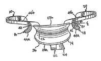
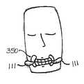
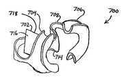
도 11a는 관련된 내부면(365, 370)에 인접한 치과 피검자의 입술을 수용하게 되는 제 1 및 제 2 반원 U자형 채널(355, 360)을 포함하는 입술 리트렉팅 장치(350)를 나타낸다. 이것은 도 1a와 유사하지만, 레디-투-유즈 구조이다. 이러한 레디-투-유즈 구조에 있어서, 일부 구성은 넌-레디-투-유즈 모드(non-ready-to-use mode)로 도시된 것과 상이한 형태를 취한다. 지지 부재(375)는 U자형 채널(355, 360)에 공동으로 결합되어 다른 하나에 대하여 거의 고정된 공간적 관계로 U자형 채널(355, 360)을 지지하게 된다. 도 11a에 도시된 본 발명의 제 1 실시형태에 의하면, 지지 부재(375)는 피검자의 혀를 유지하고, 우발적인 조명으로부터 피검자의 혀를 보호하게 되는 혀-덮개도 지지한다.FIG. 11A shows a
본 발명의 제 1 실시형태에 의하면, 한 쌍의 인터페이스 날개(111)는 각각 U자형 채널(355, 360)에 결합된다. 이 실시형태에 의하면, 인터페이스 날개(111)는 개별 상면(390, 395)과 개별 하면(401, 403)을 각각 포함한다. 본 발명의 제 1 실시형태에 의하면, 상면(390)은 저면(401)에 대하여 실질적으로 평행하게 위치결정되고, 상면(395)은 저면(403)에 대하여 실질적으로 평행하게 위치결정된다.본 발명의 제 1 실시형태에 의하면, 인터페이스 날개(111)는 제 1 복수의 틱 또는 홀(413) 및 제 2 복수의 틱 또는 홀(415)을 각각 구비한다. 틱 또는 홀은 입술 리트렉팅 장치(350)에 대하여 예컨대, 조명 프레임(도 26에 도시됨)(105) 또는 이미징 장치의 특정 배열의 유지를 용이하게 하도록 된다.According to the first embodiment of the present invention, the pair of
본 발명의 제 1 실시형태에 의하면, 인터페이스 날개(111)는 예컨대, 도 11b에 도시된 바와 같이, 라이트 가이드(106)의 슬롯(236', 238') 내에 각각 수용되도록 된다. 입술 리트렉팅 장치(350)를 라이트 가이드(106)의 전방 에지를 향하여 가압함으로써, 인터페이스 날개(111)가 슬롯(236', 238') 속으로 어징(urging)됨에 따라, 입술 리트렉팅 장치(350)의 라이트 가이드(106)에 대한 방향 및 위치가 거의 고정된다. 따라서, 피검자의 입술을 확장하여 입술 리트렉팅 장치(350)에 고정된 관계로피검자의 치아와 헤드를 효과적으로 결합하기 위해 예컨대, 도 20에 도시된 바와 같이 타겟 치아는 램프 헤드 내에 위치결정된 라이트 소스에 대하여 거의 고정된 위치를 유지하게 된다.According to the first embodiment of the present invention, the
상기한 바에 따라, 도 11c에 도시된 바와 같이, 스페이서는 전방 개구(front aperture)(1060)와 후방 개구(rear aperture)(1080) 사이에 위치결정된 엑시얼 캐버티(axial cavity)를 구비한 타원형 관상 부재(1020)를 포함하는 라이트 가이드(1000)가 될 수 있다.As described above, as shown in FIG. 11C, the spacer is elliptical with an axial cavity positioned between the
예시된 실시형태가 도시된 바와 같이, 관형 부재의 제 1 에지(1010)는 일반적 수평 부분(1100)에 관한 볼록 형상 및 일반적 수직 부분(1120)에 관한 오목 형상을 구비하는 실질적으로 타원 안장형의 곡선의 윤곽을 정한다. 또한, 에지(1010)는 제 1 및 제 2 수평 슬롯(1140, 1160)을 포함한다. 본 발명의 제 1 실시형태에 의하면, 상기 슬롯(1140, 1160)은 다른 하나에 대하여 실질적으로 동일 평면상에 위치결정되고, 에지(1010)의 윤곽을 정하는 타원 안장형 곡선의 장축과 실질적으로 일치되게 위치결정된다.As the illustrated embodiment is shown, the
림(1180)은 에지(1010)로부터 실질적으로 타원 안장형으로 굽은 제 2 에지(1200)의 안쪽을 향해 방사상으로 연장된다. 제 2 에지(1200)가 에지(1010)에 대하여 실질적으로 일정한 공간적 관계로 위치결정됨으로써 림(1180)은 에지(1010)의 길이에 걸쳐 실질적으로 일정한 방사상 치수를 갖는다. 에지(1200)는 전방 개구(1060)의 외주를 정한다.
도 11c에 도시된 실시형태의 후단부에 있어서, 제 3 에지(1300)는 실질적으로 타원 안장형의 다른 곡선의 윤곽을 정한다. 에지(1300)는 일반적인 수평 부분(1320)에 대하여 실질적으로 오목 형상이고, 일반적인 수직 부분(1340)에 대하여 실질적으로 볼록 형상이다.In the rear end of the embodiment shown in FIG. 11C, the third edge 1300 substantially contours another curve of an elliptic saddle. Edge 1300 is substantially concave with respect to general
본 발명의 제 1 실시형태에 의하면, 곡선(1300)은 라이트 가이드의 후방 개구(1080)의 윤곽을 정한다.According to the first embodiment of the invention, the curve 1300 defines the
본 발명의 제 1 실시형태에 의하면, 라이트 가이드는 후방 개구(1080)에 인접한 림을 포함하지 않는다.According to the first embodiment of the invention, the light guide does not include a rim adjacent the
예시된 실시형태에 있어서, 라이트 가이드의 외면(1390)은 에지(1010)와 에지(1300) 사이에 위치결정된다. 라이트 가이드의 내면(1360)은 상기 외면(1390)에 대하여 실질적으로 일정한 공간적 관계로 위치결정되어 타원형 관상 부재(1020)의 내부 및 외부 경계를 정한다.In the illustrated embodiment, the
본 발명의 제 1 실시형태에 의하면, 외면(1390)은 라이트 가이드(1000)의 조장 중에 외면(1390) 상의 조작자의 그립을 향상시키게 되는 복수의 그립핑 피쳐(gripping feature)(1380)를 포함한다. 예시된 실시형태에 있어서, 그립핑 피쳐(1380)는 길게 도드라진 타원면 형태를 갖는다. 본 발명의 다른 실시형태에 있어서, 그립핑 피쳐는 복수의 실질적으로 반구 범프를 포함한다. 본 발명의 또 다른 실시형태에 있어서, 그립핑 피쳐는 복수의 지그재그 홈을 포함한다. 당업자는 다양한 피쳐가 표면(1340) 상에 위치결정되어 라이트 가이드(1000)의 전체 그립퍼빌러티(gripability)를 향상시킬 수 있다는 것을 인정할 것이다.According to a first embodiment of the present invention, the
도 12에 있어서, 입술 리트렉팅 장치(10')는 피검자의 입 외부에 있게 되는 날개형 플랜지(100)와 외측벽(28b')을 제외하고 피검자의 입 내부에 위치된 모든 구성요소를 가지고 피검자의 입 내부에 있는 것으로 도시되어 있다. 쉽게 확인할 수 있는 바와 같이, 탄성 부재(20')는 입술 리트렉팅 장치(10')를 입 속으로 삽입하는 것을 방해하지 않도록 내측벽(28a')에 일체로 성형, 캐스팅 또는 부착될 수 있다.In FIG. 12, the
도 13은 램프(104)와 콘(102)를 개략적으로 나타낸 부분적 사시도이다. 콘은 램프(104)의 노즈 오프닝(nose opening)(110)과 맞물리도록 구성된다. 한 쌍의 슬롯(112)은 날개형 플랜지(100)를 수용하기 위해 콘(102)에 제공된다. 상상할 수 있는 바와 같이, 피검자에 입술 리트렉팅 장치(10')를 끼워 날개형 플랜지(100)가 슬롯(112)과 맞물리면, 피검자의 입과 램프(104) 사이의 거리가 제어될 수 있다. 또한, 날개형 플랜지(100)를 콘(102)에 고정함으로써 치료 중인 피검자에 의한 이동이 최소화될 수 있다. 당업자에게 명백한 바와 같이, 플랜지(100)의 사이즈, 슬롯(112)의 깊이, 및 콘(102)의 사이즈가 변경되어 피검자와 램프 사이의 거리와 램프에 대한 피검자의 상대적 위치가 변경될 수 있다.13 is a partial perspective view schematically illustrating
피검자가 입술 리트렉팅 장치(10')에 끼워지는 경우에 피검자에게 편안함으로 제공하기 위해 패드에는 탄성 부재(20')가 제공될 수 있다. 도 14에 도시된 바와 같이, 패드(106)는 탄성 부재(20') 상에 위치결정될 수 있다. 패드(도 15)는 고무 또는 폼(foam)으로 성형될 수 있다. 상기 고무는 천연 고무 또는 합성 고무가 될 수 있다. 합성 고무는 예컨대, 엘라스토머 물질이 될 수 있고, 스티렌-부타디엔 고무나 스티렌 이소프렌 고무, EPDM(ethylene propylene diene monomer) 고무, 니트릴(acrylonitrile butadiene) 고무, 라텍스 고무 등의 크라톤 중합체로부터 이용 가능한 블럭 공중합체(Kratons®) 또는 다양한 공중합체를 포함할 수 있지만 이것에 한정되지 않는다. 폼 물질은 클로징된 셀 폼(closed cell foam) 또는 오픈 셀 폼(open cell foam)이 될 수 있고, 폴리에틸렌 폼, 폴리프로필렌 폼, 및 폴리부틸렌 폼 등의 폴리올레핀 폼; 폴리스티렌 폼; 폴리우레탄 폼; 상기 모든 엘라스토머 또는 고무 물질로 만들어진 모든 엘라스토머 폼; 또는 폴리락트산 수진(L-락트산과 D-락트산으로 이루어짐), 및 폴리글리콜산(PGA) 등의 생분해성 또는 생화합성 폴리에스테르; 폴리히드록시발레레이트/히드록시부티레이트 수지(PHBV)[3-히드록시 부티르산과 3-히드록시 펜탄산(3-히드록시 발레르산)], 및 폴리히드록시알카노에이트(PHA) 공중합체; 및 폴리에스테르/우레탄 수지를 포함할 수 있지만 이것에 한정되지 않는다.The pad may be provided with an elastic member 20 'to provide comfort to the subject when the subject is fitted to the lip retracting device 10'. As shown in FIG. 14, the
도 15에 도시된 바와 같이, 패드는 조개껍질형 에지를 따라 결합된 두개의 절반으로 성형될 수 있다. 각각은 절반은 적어도 탄성 부재(20')의 부분을 수용하기 위해 슬롯, 채널, 또는 릿지(ridge)(108)와 일체화될 수 있다. 두개의 절반은 탄성 부재 주위에 끼워져 함께 히트 실링될 수 있다. 동일하거나 유사한 결과를 얻을 수 있는 다른 조립 방법도 고려된다. 예컨대, 릿지(108)는 패드가 탄성 부재(20')에 걸쳐 끼워지는 경우에, 패드가 탄성 부재에 대하여 슬라이딩이 가능하여 탄성 부재 상의 패드의 위치를 조정할 수 있는 사이즈로 만들어질 수 있다.As shown in FIG. 15, the pad may be molded into two halves joined along the clamshell edge. Each half may be integrated with a slot, channel, or
예컨대, 패드(106)는 폴리에틸렌 클로징된 셀 폼으로 만들어져 소독될 수 있 다. 오픈 셀 폼은 살균될 수 있다면 사용될 수도 있다.For example, the
또한, 패드는 예컨대, 부드러운 외면과 부드러운 에지를 구비하여 패드가 피검자의 입 내부와 접촉하는 경우에 불필요한 자극 없이 기분 좋게 끼워질 수 있다. 제 1 실시형태에 있어서, 패드는 입술 리트렉팅 장치(10')가 피검자의 입 내부에 있을 때 끝에서 두번째 어금니에 걸쳐 위치결정되도록 디자인될 수 있다. 또한, 패드는 예컨대, 고탄력성 물질로 만들어져서 사용 후에 원래 형태로 복원될 수 있다.In addition, the pad may, for example, have a soft outer surface and a soft edge so that the pad can be comfortably fitted without unnecessary irritation when the pad comes into contact with the inside of the mouth of the subject. In the first embodiment, the pad may be designed to be positioned over the second molar from the tip when the lip retracting device 10 'is inside the subject's mouth. In addition, the pad can be made of, for example, a highly elastic material and restored to its original form after use.
다른 실시형태에 있어서, 패드(106)는 각각의 사용 이후에 제거 가능하게 될 수 있다. 여기서, 패드는 제거 가능한 접착제를 사용하여 부착될 수 있거나, 두개의 절반은 멈추개 등을 사용하여 탄성 부재 상에 간단히 결합될 수 있다. 피검자의 입 내부에 편안하게 끼워지도록 만들어질 수 있는 폼 물질은 대체물로서 사용될 수 있다. 패드의 두개의 절반은 예컨대, 메모리를 구비하도록 히트 세트에 의해 만들어져서 탄성 부재 상의 설치를 위해 강제로 오픈되고, 오프닝 포스가 제거되면 찰깍소리를 내며 오픈될 수 있다. 두개의 절반은 하나 이상의 측면을 따라 일체로 성형 또는 부착될 수 있다.In other embodiments, the
다른 실시형태에 있어서, 패드는 영구적으로 부착되어 소독 또는 살균되지 않기 때문에 리트렉팅 장치는 사용후에 버려지게 될 일회용품이거나 한명의 피검자에게만 사용될 수 있다.In another embodiment, the retracting device may be a disposable product that will be discarded after use or may be used for only one subject because the pad is permanently attached and does not disinfect or sterilize.
또 다른 실시형태에 있어서, 패드는 적어도 탄성 부재(20) 부분의 필수 구성요소가 될 수 있다. 이 실시형태에 있어서, 하나 이상의 탄성 부재(20)는 하나 이상의 패드에 의해 결합된 두개의 부분으로 형성될 수 있다. 탄성 부재는 날카로운 에지를 최소화하기 위해 예컨대, 와이어형 구조(wire-like configuration)로 폴리메릭 또는 금속 물질에 의해 구성될 수 있다.In yet another embodiment, the pad may be at least an integral component of the portion of
도 4의 탄성 부재(20)를 다시 참조하면, 제 1 실시형태에 있어서, 탄성 부재는 폭이 좁은 중간점(70)과 이 중간점에 비해 넓은 종점(72)을 각각 포함할 수 있다. 종점(72)은 다른 종점과 비교하여 동일한 폭을 갖거나 폭이 변할 수도 있다. 이러한 배열에 있어서, 탄성 부재(20)의 바이어싱 포스(biasing force)(52)(도 3)는 종점(72)에 관한 중간점(70)의 폭에 의해 조절될 수 있다. 당업자에게 명확한 바와 같이, 중간점(70)의 폭이 넓을수록 더 큰 바이어싱 포스로 변환되는 구부러짐에 더 저항하게 된다. 따라서, 양볼과 입술을 리트렉팅하는 입술 리트렉팅 장치(10)의 리트렉팅 포스(retracting force)(52)는 중간점(70)의 폭 변경에 의해 변경될 수 있다. 리트렉팅 포스는 폴리머 또는 다른 열가소성 물질의 혼합물을 기재(base material)에 삽입(즉, 합성)하는 것과 같은 탄성 부재의 기계적 특성의 변경에 의해 변경될 수도 있다. 제 1 실시형태에 있어서, 탄성 부재는 높은 탄성률을 가진 물질로 만들어 질 수 있다.Referring back to the
본 발명의 다른 실시형태에 있어서, 리트렉팅 장치는 하나 이상의 비-상호-맞물림 포메이션을 포함할 수 있다. 비-상호-맞물림 포메이션은 피검자의 치아에 대하여 치과용 구조물을 위치결정하게 되는 덴탈 트레이를 포함할 수 있다. 이 실시형태에 있어서, 라이트 소스 또는 이미징 소스를 치과 치료중인 피검자에 반복적으로 위치결정하기 위해 날개형 부재 등의 하나 이상의 상호-맞물림 포메이션이 제공될 수도 있다.In another embodiment of the present invention, the retracting device may comprise one or more non-interlocking formations. The non-inter-engagement formation may include a dental tray that positions the dental structure relative to the subject's teeth. In this embodiment, one or more inter-engaging formations, such as a winged member, may be provided to repeatedly position the light source or imaging source on a dental subject.
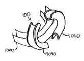
도 16은 피검자의 하부 치아 세트 또는 대안으로서 상부 치아 세트(도시되지 않음)를 수용하도록 형성 및 구성된 제 1 U자형 채널(1020)을 포함하는 본 발명에 의한 리트렉팅 장치(200)의 실시형태를 나타낸다. 입술 리트렉팅 장치(200)는 제 1 U자형 채널(1020)에 실질적으로 수직으로 장착된 제 2 U자형 채널(1040)과 제 3 U자형 채널(1060)을 더 포함한다. 제 2 및 제 3 U자형 채널(1040, 1060)은 치과 피검자의 입술을 수용하게 된다. 제 1 U자형 채널(1020)은 다른 하나에 대하여 거의 고정된 공간적 관계로 제 2 및 제 3 U자형 채널(1040, 1060)을 지지한다.FIG. 16 illustrates an embodiment of a
본 발명의 제 1 실시형태에 의하면, 한 쌍의 인터페이스 날개(202, 204)는 제 2 및 제 3 U자형 채널(1040, 1060)에 각각 결합될 수 있다. 도 13 및 도 20에 도시된 바와 같이, 피검자의 치아에 라이트 소스(104 또는 1102)를 각각 정렬하기 위해 램프 헤드 또는 라이트 소스(104 또는 1102)에 끼워지는 라이트 가이드(102 또는 1120) 내의 슬롯(112 또는 1130과 1132) 속으로 수용되도록 인터페이스 날개(202, 204)가 형성 및 구성될 수 있다. 입술 리트렉팅 장치(10 또는 1138)에 고정된 관계로 램프 헤드와 피검자의 치아를 결합하는데 피검자의 입술이 도움이 되는 효과적인 넓이를 위해, 입술 리트렉팅 장치(10 또는 1138)는 예컨대, 도 20에 도시된 바와 같이 램프 헤드 내에 위치결정된 라이트 소스에 대하여 거의 고정된 위치로 유지된다. 이것을 이하 더욱 상세히 설명한다.According to the first embodiment of the present invention, the pair of
상기 입술 리트렉팅 장치의 날개형 부재와 유사한 인터페이스 날개 또는 날개형 부재(202, 204)는 통상적으로 어느 정도의 강직도를 갖기 때문에 인터페이스 날개(202, 204)는 도 13에 도시된 바와 같이, 라이트 가이드(102) 또는 라이트 소 스(104)의 슬롯(112)과 결합될 때 효과적인 인터페이스를 형성할 수 있다. 상기 실시형태와 마찬가지로, 인터페이스 날개(202, 204)는 제 1 배열에 있어서, 채널(1020, 1040, 1060)과 동일한 물질로 형성될 수 있다. 제 2 배열에 있어서, 인터페이스 날개(202, 204)는 채널(1020, 1040, 1060)과 상이한 물질로 만들어진다.
도 16a는 도 16에 도시된 실시형태의 배면도이다. 리트렉팅 장치는 제 1 및 제 2 입술 수용 채널(1358, 1360)을 포함한다. 제 3 치아 수용 채널(1354)는 입술 수용 채널에 실질적으로 직각 방향으로 위치결정되어 피검자의 상부 또는 하부 치아를 제 3 치아 수용 채널(1354)의 오목한 영역 내에 수용하게 된다. 날개형 부재(1362, 1364) 와 같은 제 1 및 제 2 포메이션은 제 1 및 제 2 입술 수용 채널(1358, 1360)에 각각 결합된다. 예시적 실시형태가 도시된 바와 같이, 결합 부재(1356)는 제 1 및 제 2 입술 수용 채널(1358, 1360)과 치아 수용 채널(1352) 사이에 위치결정되어 서로 결합된다. 다양한 실시형태에 있어서, 리트렉팅 장치는 상부 치아 및 하부 치아를 동시에 수용하도록 배열된 한 쌍의 치아 수용 채널을 포함한다는 것은 당업자에게 자명하다.FIG. 16A is a rear view of the embodiment shown in FIG. 16. FIG. The retracting device includes first and second
사용시에 있어서, 리트렉팅 장치(1350)는 치아 수용 채널(1352)의 오목 영역(1354) 내의 치과 미백 성분 또는 치과 캐스팅 성분 등의 치과 성분(dentistry compositon)을 수용하게 된다. 미백 성분은 빛에 활성화 가능하게 될 수 있거나 어둠에서 활성화 가능하게 될 수 있다. 치아 수용 채널은 소망하는 애플리케이션에 따라 투명, 반투명, 또는 불투명하게 될 수 있다.In use, the
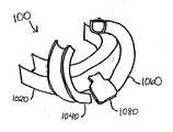
도 17은 본 발명의 제 1 실시형태에 의한 덴탈 트레이 또는 치아 수용 채널 을 포함하는 입술 리트렉팅 장치(1000)를 나타낸다. 입술 리트렉팅 장치(1000)는 피검자의 하부 치아 또는 대안으로서 상부 치아(도시되지 않음)를 수용하도록 형성 및 구성된 제 1 U자형 채널(1020)을 포함한다. 입술 리트렉팅 장치(1000)는 제 1 U자형 채널(1020)에 실질적으로 수직으로 장착되고, 치과 피검자의 입술을 수용하게 되는 제 2 U자형 채널(1040) 및 제 3 U자형 채널(1060)을 더 포함하고, 치아가 실질적으로 깨끗한 피검자의 입술을 유지하는 입술 리트렉팅 장치로서 기능한다. 제 1 U자형 채널(1020)은 다른 하나에 대하여 거의 고정된 공간적 관계로 제 2 및 제 3 U자형 채널을 지지한다.17 shows a
제 1 U자형 채널(1020)은 미백 성분을 수용하도록 다시 구성될 수 있다. 제 1 U자형 채널(1020)은 피검자의 치아에 걸쳐 끼워져 미백 성분이 피검자의 치아와 접촉할 수 있게 된다. 제 2 및 제 3 U자형 채널(1040, 1060) 내의 피검자의 입술은 피검자측의 노력 없이 치아의 청결이 실질적으로 유지된다. 또한, 피검자의 입술의 원래 압력은 도 28c에 도시된 바와 같이, 피검자측의 노력 없이 위치 내에 입술 리트렉팅 장치를 유지할 수도 있다.The first
입술 리트렉팅 장치(1000)는 피검자에 끼워지기에 충분하게 유연하게 될 수 있고, 적절하게 미백 성분을 지지하고, 피검자의 입술을 지지하기에 충분하게 단단하게 될 수 있다. 따라서, 입술 리트렉팅 장치(1000)는 상기 모든 폴리머로 만들어질 수 있다.The
본 발명의 실시형태에 있어서, U자형 채널(1020, 1040, 1060)은 동일한 물질로 만들어진다. 본 발명의 제 2 실시형태에 있어서, 제 1 U자형 채널(1020)은 제 2 및 제 3 U자형 채널(1040, 1060)과 상이한 물질로 만들어진다. 제 1 예시적 배열에 있어서, 제 1 U자형 채널(1020)은 고무로 만들어질 수 있고, 제 2 및 제 3 U자형 채널(1040, 1060)은 플라스틱으로 만들어질 수 있다. 제 2 예시적 배열에 있어서, 제 2 및 제 3 U자형 채널(1040, 1060)은 자외선이 실질적으로 침투할 수 없는 물질로 만들어지는 반면, 제 1 U자형 채널(1020)은 자외선 침투가 가능한 물질로 만들어질 수 있다. 본 실시형태에 있어서, 제 2 및 제 3 U자형 채널(1040, 1060)은 피검자의 부드러운 조직을 위한 약간의 보호를 제공하는 반면 제 1 U자형 채널(1020)은 자외선의 침투가 치아를 하얗게 하기 때문에 광활성화 성분이 사용될 수 있다.In an embodiment of the invention, the
다른 대체 실시형태에 있어서, 제 1 U자형 채널(1020)은 피검자의 치아에 맞춤식으로 만들어질 수 있다. 본 실시형태에 있어서, 피검자의 치아의 자국이 만들어져서 제 1 U자형 채널(1020)은 이 자국을 사용하여 제작될 수 있다.In another alternative embodiment, the first
다른 대체 실시형태에 있어서, 제 1 U자형 채널(1020)은 미백 성분을 포함하는 물질로 만들어질 수 있다. 제 1 배열에 있어서, 포함된 미백 성분은 입술 리트렉팅 장치가 피검자에게 적용되기 전에 피검자의 치아에 실질적으로 적용함으로써 활성화될 수 있다. 제 2 배열에 있어서, 포함된 미백 성분은 치과 피검자의 침에 의해 활성화될 수 있다. 본 실시형태에 있어서, 통상적으로 제 1 U자형 채널의 외형은 피검자의 부드러운 조직을 보호하는 물질층으로 덮여진다. 제 3 배열에 있어서, 포함된 미백 성분은 광에 의해 활성화된다. 제 4 배열에 있어서, 미백 성분은 어둠속에서 활성화 가능하게 될 수 있다.In another alternative embodiment, the first
도 18은 제 1 U자형 채널에 실질적으로 수직인 제 2 U자형 채널(1040) 및 제 3 U자형 채널(1060)에 공동으로 결합된 제 1 U자형 채널(1020)을 구비한 입술 리트렉팅 장치(100)를 나타낸다. 탭(1080)은 제 2 및 제 3 U자형 채널(1040, 1060) 사이의 제 1 U자형 채널(1020)에 결합되어 있다. 탭(1080)은 입술 리트렉팅 장치(100)를 치과 피검자의 입에 위치결정하는데 유용하다. 나중에, 미백 처리가 완료된 후, 탭(1080)은 치과 피검자의 입으로부터 입술 리트렉팅 장치(1000)를 제거하는데 유용하다.18 shows lip retracting with a second
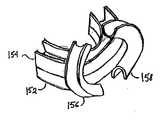
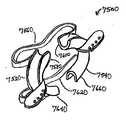
도 19는 본 발명의 원리에 의한 입술 리트렉팅 장치의 대체 실시형태를 나타낸다. 입술 리트렉팅 장치(150)는 아래턱 U자형 채널(152) 및 위턱 U자형 채널(154)을 포함한다. 아래턱 U자형 채널(152)은 피검자의 하부 치아 세트(도시되지 않음)를 수용하도록 형성 및 구성되고, 위턱 U자형 채널(154)은 피검자의 상부 치아 세트(도시되지 않음)를 수용하도록 형성 및 구성된다. 아래턱 U자형 채널(152) 및 위턱 U자형 채널(154) 모두 미백 성분 등의 치료 성분을 수용하게 된다. 입술 리트렉팅 장치(150)는 제 1 U자형 입술 리트렉팅 장치 채널(156) 및 제 2 U자형 입술 리트렉팅 장치 채널(158)을 더 포함하고, 이 두 채널은 하래턱 U자형 채널(152) 및 위턱 U자형 채널(154)에 실질적으로 수직으로 장착된다. 아래턱 U자형 채널(152) 및 위턱 U자형 채널(154)은 다른 하나에 대하여 거의 고정된 공간적 관계로 제 1 U자형 입술 리트렉팅 장치 채널(156) 및 제 2 U자형 입술 리트렉팅 장치 채널(158)을 지지한다. 제 1 및 제 2 U자형 입술 리트렉팅 장치 채널(156, 158)은 치과 피검자의 입술을 수용하도록 형성 및 구성된다.19 shows an alternative embodiment of a lip retracting device in accordance with the principles of the present invention. Lip retracting device 150 includes lower jaw
시행중에 있어서, 아래턱 U자형 채널(152) 및 위턱 U자형 채널(154)은 각각 미백 성분을 수용할 수 있다. 아래턱 U자형 채널(152) 및 위턱 U자형 채널(154)은 피검자의 치아에 끼워져서 미백 성분 등의 치료 성분이 피검자의 치아와 접촉하게 된다. 피검자의 입술은 제 1 및 제 2 U자형 입술 리트렉팅 장치 채널(156, 158) 내에 수용된다. 본 실시형태의 치과용 입술 리트렉팅 장치를 사용하여, 전체 작업 시간을 효과적으로 감소시킴과 동시에 미백 처리 등의 치과적 처리가 하부 치아와 상부 치아 상에 수행될 수 있다.In operation, the lower jaw
도 20은 본 발명의 제 1 실시형태에 의한 라이트 시스템(1102), 라이트 가이드(1120), 및 입술 리트렉팅 장치(1122)의 상호-맞물림 포메이션 사이의 조립 관계를 나타낸다. 예컨대, 하나의 포메이션에 있어서, 피봇 마운트(pivot mount)(906)는 볼 조인트(ball joint)(902) 등의 다른 포메이션을 램프 헤드(1102)에 결합한다. 볼 조인트(902)는 램프 헤드(1102)가 공간상에서 회전되게 하여 램프 시스템의 광학축을 예컨대, 치과 미백 피검자의 타겟 치아에 정렬시킬 수 있다.20 illustrates an assembly relationship between the inter-engagement formation of the
하나 이상의 포메이션을 구비한 라이트 가이드(1120)는 다른 포메이션에 의해 램프 헤드(1102)의 전방 단부에 결합되게 된다. 제 1 실시형태에 있어서, 라이트 가이드(1120)는 램프 헤드(1102)의 외면 영역(1124)에 근접하여 유지되게 되는 내면 영역(1122)을 포함한다. 본 발명의 제 1 실시형태에 의하면, 돌출 부재 또는 범프(bump) 등의 내면(1122) 상의 포메이션은 외면 영역(1124)의 오목 영역(1126) 등의 포메이션 내에 어징(urging)되게 된다.The
본 발명의 제 1 실시형태에 있어서, 라이트 가이드(1120)는 그 전방 에지에 탄성 압축 가능한 쿠션(1128)을 포함한다. 탄성 압축 가능한 쿠션(1128)은 치과 미 백 처리 피검자(도시되지 않음)와 라이트 가이드(1120) 사이의 인터페이스를 부드럽게 하는 기능을 할 수 있다.In the first embodiment of the present invention, the
본 발명의 다른 형태에 있어서, 예시적 실시형태가 도시된 바와 같이, 라이트 가이드(1120)는 제 1 및 제 2 슬롯(1130, 1132) 등의 포메이션을 포함한다. 이 슬롯은 입술 리트렉팅 장치(1138)의 돌출 날개(1134, 1136) 등의 포메이션을 수용하게 되어 예컨대, 치과 미백 피검자와 램프 헤드(1102) 사이의 관계를 안정시킬 수 있다.In another form of the invention, as the exemplary embodiment is shown, the
입술 리트렉팅 장치(1138)는 미백 또는 다른 치과 처리 중에 치과 미백 피검자의 입술을 지지하게 되는 채널(1140, 1142), 및 탄성 부재(1144)를 포함한다. 탄성 또는 탄력 부재(1144)는 채널(1140, 1142)에 결합되고, 입술을 향해 외측으로 채널을 어징하게 되어 치과 처리 중인 피검자를 입술 리트렉팅 장치에 결합하게 된다.
피검자가 입술 리트렉팅 장치에 결합되고, 입술 리트렉팅 장치가 라이트 가이드(1120) 내의 각각의 슬롯(1130, 1132) 내에 날개형 부재(1134, 1136)을 삽입함으로써 라이트 가이드(1120)에 결합되면, 피검자는 램프 헤드(1102)에 대하여 공간적으로 안정되게 된다. 이러한 방식으로 지지 구조는 예컨대, 미백 피검자에 관한 실질적으로 안정된 공간적 관계로 램프 헤드를 지지하는 기능을 한다.The subject is coupled to the lip retracting device, and the lip retracting device is coupled to the
상기한 바와 같이, 피검자와 본 발명의 지지 구조 사이의 이러한 공간적으로 안정된 관계는 다양한 장치와 프로세스에 대하여 본 발명의 다른 실시형태에서 발견된다.As noted above, this spatially stable relationship between the subject and the support structure of the present invention is found in other embodiments of the present invention for various devices and processes.
본 발명의 다른 실시형태에 의하면, 라이트 가이드(1120)는 피검자가 라이트 가이드 장치의 사용 중에 더 쉽게 호흡할 수 있게 된 하나 이상의 통풍구(도시되지 않음)을 포함할 수 있다.According to another embodiment of the present invention, the
제 1 실시형태에 있어서 탄성 압축 가능 부재(1128)는 예컨대, 폴리머 폼 또는 고무로 만들어지고, 접착제 또는 히트 실링에 의해 라이트 가이드(1120)에 부착된다. 적절한 접착제는 핫멜트 접착제(hot melt adhesive), 압력 감응형 접착제(pressure sensitive adhesive), 반응형 접착제(reactive adhesive) 등을 포함할 수 있지만 이것에 한정되지 않는다. 대안으로서, 적절한 접착제는 아크릴계, 폴리우레탄계, 에폭시계, 폴리아미드계, 시아노아크릴레이트계, 스티렌 코폴리머계, 폴리올레핀계 등이 될 수 있다. 또한, 예컨대, 부호 1128a 및 1128b와 같이 조각으로 나뉘어 존재할 수 있는 탄성 압축 가능 부재(1128)는 라이트 가이드상에 일체로 성형될 수 있다.In the first embodiment the elastic
본 실시형태에 있어서, 쿠셔닝 탄성 부재(1128)는 라이트 가이드의 슬롯(1130, 1132)을 연장하는 두개의 조각인 상부(1128a)와 하부(1128b)으로 만들어져서 예시적 입술 리트렉팅 장치의 날개 부재를 수용할 수 있다.In this embodiment, the cushioning
라이트 가이드의 탄성 쿠셔닝 부재(1128) 또는 입술 리트렉팅 장치의 탄성 부재(1144)는 상기 설명한 바와 같이 입술 리트렉팅 장치의 패드로서 유용한 오픈 셀 또는 클로징된 셀 폼이 될 수 있는 모든 폼 물질로 만들어질 수 있다.The
에어 벤트는 공기를 통과시키지만 라이트 가이드(1120)의 빛의 누설을 방지하도록 구성될 수 있다.The air vent may be configured to allow air to pass but prevent light leakage of the
본 발명의 제 1 실시형태에 의하면, 도 20에 도시된 바와 같이, 라이트 가이드(1120)는 일회용 아이템으로 구성되어 한번의 치과 미백 치료를 위해 사용된 후에 버려질 수 있다. 이것을 염두에 두고, 상기한 바와 같이, 라이트 가이드(1120)는 그 배면에 성형된 공간(2040) 내에 위치결정된 메모리 집적 회로(2120)를 더 포함한다. 도 25에 도시된 바와 같이, 메모리 집적 회로(2120)는 특정 라이트 가이드가 얼마나 오래 사용되었는지를 나타내는 사용 기간 신호의 기록을 저장한다. 라이트 가이드 메모리 집적 회로(2120)는 라이트 가이드(1120)가 부적당하게 재사용되지 않게 하는 시스템의 일부가 될 수 있다. 라이트 가이드(1120)는 포함된 메모리 칩을 구비함으로써 한명의 피검자에게 사용되는 아이템이 되도록 구성될 수도 있다.In accordance with a first embodiment of the present invention, as shown in FIG. 20, the
도 21은 예컨대, 본 발명의 실시형태와 함께 사용하기에 적합한 치과 미백 시스템의 제 1 실시형태를 나타낸다. 치과 미백 램프 시스템(300)의 사시도는 램프 헤드 하우징(304)을 구비한 램프 헤드(302) 및 라이트 가이드(306)를 포함한다. 램프 헤드(302)가 라이트를 제공하여 램프 헤드 하우징(304)에서 라이트를 발생시키고, 라이트 가이드(306)를 통해 라이트를 디렉팅함으로써 피검자의 치아에 적용되는 미백 또는 충전 물질을 활성화한다. 이 램프 시스템(300)은 치과 병원 또는 치과 연구소에서 사용될 수 있다.21 shows, for example, a first embodiment of a dental whitening system suitable for use with embodiments of the present invention. The perspective view of the dental
램프 하우징은 라이트 소스와 램프 하우징 쿨을 보관하기 위해 라이트 소스에 근접하여 하나 이상의 히트 싱크(heat sink)를 포함할 수도 있다. 히트 싱크는 구리, 알루미늄 등의 금속 블럭(metal block)을 포함하는 양호한 열 전도성을 갖는 물질로 만들어질 수 있다. 다른 실시형태에 있어서, 일부 실시형태 및 물질이 여기에 참조로서 포함된 컨텐츠인 "Dental Light Devices With Phase Change Material Filled Heat Sink"라는 발명의 명칭을 가지고 2004년 7월 2일에 출원된 미국 특허출원 No. 60/585,224에 개시되어 있는 바와 같이, 쿨링 시스템(cooling system)은 상변화 물질을 포함한다.The lamp housing may include one or more heat sinks in proximity to the light source for storing the light source and the lamp housing cool. The heat sink may be made of a material having good thermal conductivity, including metal blocks such as copper, aluminum, and the like. In another embodiment, a U.S. patent application filed on Jul. 2, 2004, entitled “Dental Light Devices With Phase Change Material Filled Heat Sink,” the content of which some embodiments and materials are incorporated herein by reference No. As disclosed in 60 / 585,224, a cooling system includes a phase change material.
상변화 물질 내부를 보호하기 위해 캐핑(capping)하기 전에 하나 이상의 상변화 물질을 빈공간에 부분적으로 채우고, 금속 등의 열전도성 물질을 홀로잉 아웃(hollowing out)시킴으로써 히트 싱크가 구성되어 하나 이상의 상변화 물질은 종래 히트 싱크의 구성에 통상적으로 사용되는 금속 등의 열전도 물질을 실질적으로 포함되거나 이 열전도 물질에 의해 둘러싸여지게 된다.The heat sink is constructed by partially filling one or more phase change materials into a void before capping to protect the interior of the phase change material, and hollowing out thermally conductive materials such as metal to form one or more phases. The change material may substantially include or be surrounded by a heat conductive material such as a metal commonly used in the construction of a conventional heat sink.
대안으로서, 히트 싱크는 구멍 또는 빈공간을 둘러싸는 벽을 생성하기 위해 금속 등의 열전도 물질로 캐스팅(casting) 또는 기계가공될 수 있다. 구멍 또는 빈공간은 상변화 물질 내부를 보호하기 위해 캐핑되기 전에 하나 이상의 상변화 물질로 부분적으로 채워진다.Alternatively, the heat sink may be cast or machined with a thermally conductive material such as metal to create a wall that encloses the hole or void. The holes or voids are partially filled with one or more phase change materials before they are capped to protect the interior of the phase change material.
본 발명의 제 1 실시형태에 있어서 히트 싱크 그 자체가 사용될 수 있다. 다른 실시형태에 있어서, 종래 금속 블럭 히트 싱크 또는 그 조합과 함께 팬(fan)에 추가로 히트 싱크가 사용될 수 있다.In the first embodiment of the present invention, the heat sink itself can be used. In other embodiments, heat sinks may be used in addition to fans in conjunction with conventional metal block heat sinks or combinations thereof.
적합한 상 변화 물질은 유기 물질, 무기 물질, 및 그 조합물을 포함할 수 있다. 이러한 물질은 실질적으로 역으로 상변화될 수 있고, 무한한 사이클이 아니라면 효율을 잃지 않고 전형적으로 다수의 사이클을 거칠 수 있다. 유기 상변화 물질 은 파라핀 왁스, 2,2-디메틸-n-도코산(C24H50), 트리미리스틴(trimyristin), (C13H27COO)3C3H3), 및 1,3-메틸 펜타코산(C26H54)을 포함한다. 소디엄 하이드로젠 포스페이트 도데카하이드레이트(Na2HPO4ㆍ12H2O), 소디엄 설페이트 데카하이드레이트(Na2SO4ㆍ10H2O), 염화 제2철 6수화물(FeCl3ㆍ6H2O), 및 TH29(오스트레일리아 TEAP Energy of Wangara로부터 입수 가능한 29℃의 녹는점을 가진 수화염) 또는 Ostalloy 117 또는 UM47(Umicore Electro-Optic Materials로부터 입수 가능함)과 같은 금속 합금을 포함하는 수화염 등의 무기 물질도 고려된다. 예시적인 물질은 약 30℃ ~ 약 50℃, 또는 약 35℃ ~ 약 45℃의 녹는점을 가지며, 대기 온도에서 고체이다. 또한, 예시적인 물질은 대기 온도하의 상태에 있을 경우, 높은 비열, 예컨대, 적어도 약 1.7, 또는, 적어도 약 1.9의 비열을 갖는다. 또한, 상변화 물질은 상승된 온도하의 상태에 있을 경우, 예컨대, 적어도 약 1.5, 또는, 적어도 약 1.6의 비열을 갖는다.Suitable phase change materials can include organic materials, inorganic materials, and combinations thereof. Such materials can be substantially reversed in phase and typically go through multiple cycles without losing efficiency unless they are infinite cycles. Organic phase change materials are paraffin wax, 2,2-dimethyl-n-docoic acid (C24 H50 ), trimyristin, (C13 H27 COO)3 C3 H3 ), and 1,3 Methyl pentacoic acid (C26 H54 ). Sodium hydrogen phosphate dodecahydrate (Na2 HPO4 12H2 O), sodium sulfate decahydrate (Na2 SO4 10H2 O), ferric chloride hexahydrate (FeCl3 6H2 O), And inorganic materials such as hydrated salts including metal alloys such as TH29 (hydrated salt with a melting point of 29 ° C. available from Australia's TEAP Energy of Wangara) or Ostalloy 117 or UM47 (available from Umicore Electro-Optic Materials). Is considered. Exemplary materials have a melting point of about 30 ° C. to about 50 ° C., or about 35 ° C. to about 45 ° C., and are solid at ambient temperature. In addition, the exemplary material has a high specific heat, such as at least about 1.7, or at least about 1.9 when it is at ambient temperature. In addition, the phase change material has a specific heat of, for example, at least about 1.5, or at least about 1.6 when in a state of elevated temperature.
상변화 물질은 상당한 량의 열 에너지를 저장하기 위해 용해물의 높은 잠열을 가질 수도 있다. 이 용해물의 잠열은 예컨대, 적어도 약 30kJ/㎏, 또는 적어도 약 200kJ/㎏이 될 수 있다.The phase change material may have a high latent heat of melt to store a significant amount of thermal energy. The latent heat of this lysate can be, for example, at least about 30 kJ / kg, or at least about 200 kJ / kg.
물질의 열 전도성은 열 전도성 케이싱으로부터 상변화 물질로의 열전달율 및 상변화 물질로부터 열적 전도 케이싱으로의 열전달율을 결정하는 요소가 된다. 상변화 물질의 열 전도성은 예컨대, 대기 온도 상태에서 적어도 약 0.5W/m℃, 상승된 온도 상태에서 적어도 약 0.45W/m℃가 될 수 있다.The thermal conductivity of the material is a factor in determining the heat transfer rate from the thermally conductive casing to the phase change material and the heat transfer rate from the phase change material to the thermally conductive casing. The thermal conductivity of the phase change material may be, for example, at least about 0.5 W / m ° C. at ambient temperature and at least about 0.45 W / m ° C. at elevated temperature.
일반적으로, 상변화 물질은 금속 케이싱 등의 열 전도성 물질 내부에 포함될 수 있다. 케이싱은 예컨대, 원통형 또는 직사각형 등의 모든 형태가 될 수 있는 구멍을 규정한다. 구멍의 벽 또는 금속 케이싱은 상변화 물질을 포함하고, 상변화 물질로부터의 열전도 및 상변화 물질로의 열전도를 촉진하는 작용을 한다. 벽이 얇을수록 더 많은 상변화 물질이 주어진 히트 싱크의 사이즈 내에 존재할 수 있고, 예컨대, 큐어링 라이트(curing light)의 웨이트(weight)를 줄이는데 기여한다. 그러나, 벽이 얇을수록, 상변화 물질로부터의 열전달에 있어서 히트 싱크가 효과적으로 감소될 수 있고, 상변화 물질을 대기 온도 상태 및 그 원래 상태로 리턴시키는데 더 오래 걸리게 되어 다시 히트 싱크로서 기능할 수 있게 된다. 예컨대, 벽 두께는 약 1㎜ ~ 약 2.5㎜, 또는 약 1㎜ ~ 약 1.5㎜의 범위가 된다.In general, the phase change material may be included inside a thermally conductive material such as a metal casing. The casing defines a hole that can be any shape, for example cylindrical or rectangular. The wall of the hole or the metal casing comprises a phase change material and acts to promote heat conduction from the phase change material and heat conduction to the phase change material. The thinner the wall, the more phase change material can be present in a given heat sink size, contributing to reducing the weight of the curing light, for example. However, the thinner the wall, the more effectively the heat sink can be reduced in heat transfer from the phase change material, and the longer it takes for the phase change material to return to its atmospheric temperature state and its original state so that it can function as a heat sink again. do. For example, the wall thickness ranges from about 1 mm to about 2.5 mm, or from about 1 mm to about 1.5 mm.
케이싱은 큰 표면적을 갖도록 구성될 수도 있다. 열전도 또는 열전달을 위한 표면적을 증가시키는 핀(fin) 또는 다른 피쳐를 구비한 구조가 바람직하기 때문에 구면 구조가 유용하지만 최선의 선택은 아니다. 이러한 핀 또는 다른 표면적 증가 피쳐는 열전도 케이싱과 상변화 물질 사이의 접촉을 증가시키기 위해 구멍 내에 일체화될 수 있기 때문에 열전도 케이싱과 상변화 물질 사이의 더 빠르고 효율적인 열 전달을 가능하게 한다.The casing may be configured to have a large surface area. Spherical structures are useful but not the best choice because structures with fins or other features that increase the surface area for heat conduction or heat transfer are desirable. Such fins or other surface area increasing features can be integrated into the holes to increase contact between the thermally conductive casing and the phase change material, thereby allowing for faster and more efficient heat transfer between the thermally conductive casing and the phase change material.
열전도 케이싱은 라이트 소스로부터의 열전달을 위해 양호한 열 접촉을 제공할 수도 있다. 이것은 접촉면이 넓은 부드러운 열전도면으로 달성될 수 있다. 또한, 열적 결합은 서멀 에폭시(thermal epoxy) 등의 열전도성 인터페이스 물질로 성취될 수 있다. 전기적 절연이 되는 인터페이스 물질은 열전도의 손실 없는 전기적 센스에 있어서 히트 싱크로부터 라이트 소스를 분리하는데도 유용하다.Thermally conductive casings may provide good thermal contact for heat transfer from the light source. This can be achieved with a smooth thermally conductive surface with a wide contact surface. Thermal bonding can also be accomplished with thermally conductive interface materials such as thermal epoxy. Electrically insulating interface materials are also useful for separating light sources from heat sinks in an electrical sense without loss of heat conduction.
램프 헤드(302)는 붐(308)의 제 1 단부에 부착될 수 있다. 램프 헤드(302)는 붐(308)에 대하여 위치결정될 수 있고, 붐(308)의 단부에 대하여 넓은 동작 범위를 갖는다. 붐(308)은 마스트(310)에 의해 지지된다. 예시된 실시형태에 있어서, 붐(308)은 램프 헤드 하우징(304)보다 붐(308)의 제 2 단부에 더 근접한 붐(308) 상의 포인트에서 마스트(310)에 피봇 가능하게 장착된다.The
붐(308)은 마스트(310)에 대하여 조정 가능하게 위치결정될 수 있다. 붐(308)은 마스트(310)에 대하여 회전가능하고 기울어진 동작 범위를 갖는다. 붐(308)의 제 2 단부 상의 평형추(322)는 램프 헤드(302)에 균형을 제공한다. 마스트(310)는 베이스(312)에 부착된다. 예시된 실시형태에 있어서, 베이스(312)는 롤링 베이스(rolling base)이다.The
롤링 베이스(312)는 전체 램프 시스템(300)이 치과 의자 내의 피검자에 대하여 위치결정될 수 있게 한다. 또한, 본 발명의 다른 실시형태에 있어서의 마스트(310)는 베이스(312)에 대하여 축방향으로 회전 가능하게 될 수 있다. 본 발명의 제 1 실시형태에 의하면, 마스트(310)는 곡선 모양이기 때문에 이 곡선은 마스트(310)의 오목 측면(324)과 볼록 측면(326)을 나타낸다. 예시된 실시형태에 있어서, 파워 팩(314)은 볼록 측면(326) 상의 마스트(310)에 부착된다. 파워 팩(314)은 램프 시스템(300)을 위한 조종장치를 포함한다.The rolling base 312 allows the
동작시에 있어서, 램프 시스템(300)은 치과 의자(도시되지 않음) 내의 피검자에 대하여 위치결정될 수 있다. 램프 시스템(300)이 피검자에 대하여 위치결정되 면, 오퍼레이터는 상기한 바와 같이 피검자의 입에 라이트 가이드(306)를 정렬시킬 수 있다. 대체 실시형태에 있어서, 라이트 가이드(306)는 램프 헤드(302)의 필수 구성요소가 될 수 있다.In operation,
라이트 가이드(306)는 마스트(310)에 관한 붐(308) 및 붐(308)에 관한 램프 헤드(302)의 넓은 동작 범위에 걸쳐 넓은 범위의 위치로 설정될 수 있다. 라이트 가이드(306)는 도 16에 도시된 피검자가 착용한 입술 리트렉팅 장치와 같이 인터페이스 날개를 가진 입술 리트렉팅 장치와 결합되도록 형성 및 구성되어 피검자의 입에 실질적으로 정밀한 배열을 제공한다.The
도 22는 본 발명과 함께 사용하기에 적합한 도 21의 램프 헤드(302)의 사시도이다. 램프 헤드(302)는 상기한 바와 같이, 램프 헤드 하우징(304) 및 라이트 가이드(306)를 포함한다. 램프 헤드 하우징(304)는 라이트 가이드(306)을 통해 빛을 생성하여 디렉팅(directing)한다. 본 실시형태에 있어서, 램프 헤드 하우징(304)은 벌브(bulb) 등의 라이트 소스로 빛을 생성한다. 램프, 할로겐 라이트 소스 등의 아크 램프(arc lamp), 반도체 라이트 에미팅 장치, LED, 고체 상태 LED, LED 어레이 등의 라이트 에미팅 칩, 및 형광 벌브 등을 포함하는 다른 타입의 라이트 소스가 본 발명의 범위 내에서 가능하다. 덴탈 이미징의 경우에 있어서, 라이트 소스는 상기 레이저에 더하여 엑스레이 또는 적외선 소스도 포함할 수 있다. 라이트 가이드(306)는 램프 시스템(300)과 예컨대, 치과 미백 치료를 받는 피검자 사이의 인터페이스로서의 기능을 할 수 있다.22 is a perspective view of the
본 발명의 제 1 실시형태에 의하면, 라이트 가이드(306)는 램프 시스템(300) 과 치과 미백 치료를 받는 피검자 사이의 인터페이스로서의 기능을 한다. 라이트 가이드(306)의 구조는 피검자의 피부를 자외선 노출로부터 보호하기 위해 자외선 억제 물질을 포함한다. 라이트 가이드(306)는 통상적으로 타원형 뷰드처럼 형성된다. 라이트 가이드(306)의 전방 개구(342)의 반대면 상에 커팅된 제 1 슬롯(336)과 제 2 슬롯(338)은 램프 헤드(302)를 화자에 정확히 정렬하기 위해 도 23에 도시된 바와 같이, 입술 리트렉팅 장치(200) 상의 인터페이스 날개(202, 204)에 정렬된다.According to the first embodiment of the present invention, the
다른 실시형태에 있어서, 조명 프레임 내의 기하학적 배열 내에 위치결정된 멀티플 라이트 소스는 조명 시스템 내에 사용될 수 있다. 제 1 실시형태에 있어서, 라이트 소스는 아치형 형태로 배열될 수 있고, 예컨대, 도 24에 도시된 바와 같이, 피검자의 턱 모양으로 될 수 있다.In other embodiments, multiple light sources positioned within the geometry within the lighting frame can be used within the lighting system. In the first embodiment, the light sources may be arranged in an arcuate form, for example, as shown in FIG. 24, in the shape of the jaw of the subject.
도 24에 있어서, 조명 프레임(105)는 아치 형상을 갖고, 치아에 조명을 제공하도록 구성된다. 아치 형상은 사람의 턱 곡선을 따르게 되어 라이트 소스는 라이트 소스가 디렉팅되는 쪽으로 향한 여러 치아로부터 실질적으로 등거리가 된다. 조명 프레임(105)은 전면(225)과 후면(230)을 구비한다. 전면(225)은 오목면이고, 후면(230)은 볼록면이다. 튜브(15)는 조명 프레임(105)의 후면(230)에 부착된다. 튜브(115)는 조명 프레임(105)를 지지하고, 조명 프레임(105)의 배선을 위한 도관으로서의 기능도 한다. 복수의 라이트 소스(235)는 조명 프레임(105)의 전면(225)을 따라 배열된다. 라이트 소스는 상기한 것들 중 어느 것이라도 될 수 있지만 이것에 한정되지 않는다. 라이트 소스(235)는 예컨대, 미백 또는 큐어링 프로세스를 위해 피검자의 치아(도시되지 않음)를 향하여 빛을 생성하여 디렉팅한다. 제 1 실시형태 에 있어서, 라이트 소스(235)는 실질적으로 동일한 라이트 스펙트럼을 갖는 빛을 낸다. 제 2 실시형태에 있어서, 라이트 소스(235)는 상이한 스펙트럼을 갖는 빛을 낸다. 본 발명의 제 1 실시형태에 있어서, 라이트 소스(235)는 조명 프레임(225)의 전면으로부터 돌출된다. 대체 실시형태에 있어서, 라이트 소스(235)는 조명 프레임(225)의 전면과 실질적으로 같은 높이로 위치결정된다.In FIG. 24, the
멀티플 라이트 소스를 가진 조명 시스템에 있어서, 라이트 소스들에는 공동으로 또는 개별적으로 전원이 공급될 수 있다. 개별적으로 전원이 공급되면, 각각의 라이트 소스는 원하는 바에 따라 개별적으로 온 또는 오프가 될 수 있다. 이것은 하나 또는 두개의 치아가 치료 또는 검사될 수 있는 경우에 있어서, 큐어링 또는 이미징 프로세스에 특히 유용하다.In a lighting system with multiple light sources, the light sources may be powered jointly or separately. When powered separately, each light source can be individually turned on or off as desired. This is especially useful for curing or imaging processes where one or two teeth can be treated or examined.
제 1 형태에 있어서, 조명 프레임(225)는 도 25에 도시된 바와 같이, 라이트 가이드 하우징 내에 위치결정될 수 있다. 도 20에 도시되고 전술한 바와 같이, 탄성 부재(1128)는 피검자와 라이트 가이드(1120) 사이에 위치결정된다. 탄성 부재(1128)는 피검자와 라이트 가이드 사이의 인터페이스에 아프거나 거북할 수 있는 충격을 흡수하는 쿠션으로서의 기능을 한다.In a first form, the
라이트 가이드(1120)는 도 20과의 관계에 있어서 상기한 바와 유사하게, 입술 리트렉팅 장치(1138)에 결합될 수 있다.The
다른 형태에 있어서, 조명 프레임은 도 24, 도 25, 및 도 26에 도시된 바와 같은 셀프-콘테인드 구조(self-contained structure)로서 램프 헤드 하우징을 대신할 수 있다. 도 26에 있어서, 조명 프레임(105)은 통상적으로 제 1 단부(500) 및 제 2 단부(505)를 구비한 아치 형상을 갖는다. 조명 프레임(105)의 후면(230)도 볼록면이고, 조명 프레임(105)의 전면도 오목면이다. 각 단부(500, 505)는 조명 프레임(105)의 전면(225)으로부터 조명 프레임(105)의 후면(230)을 향하여 개방된 슬롯(510, 515)을 구비한다. 각 슬롯(510, 515)은 조명 프레임(105)의 각 단부(500, 505)로부터 내측으로 확장된다. 슬롯(510, 515)은 상기한 바와 같이 입술 리트렉팅 장치의 날개와 결합되도록 위치결정되고 구성된다.In another form, the illumination frame may replace the lamp head housing as a self-contained structure as shown in FIGS. 24, 25, and 26. In FIG. 26, the
도 25a는 본 발명의 제 1 실시형태에 의한 히트 싱크를 포함하는 조명 프레임(105)의 평면도이다. 조명 프레임(105)은 그 밸러스트(ballast)(또는 베이스)에 결합된 히트 싱크(650)를 가진 복수의 라이트 소스(235)를 구비한다. 히트 싱크(650)는 상변화 물질을 포함하는 전술한 물질로 만들어질 수 있다. 히트 싱크는 어떤 형태로도 될 수 있다.25A is a plan view of an
도 28은 본 발명의 제 1 실시형태에 의한 조명 프레임(105)에 결합된 입술 리트렉팅 장치(350)의 평면도이다. 입술 리트렉팅 장치(350)는 타겟 치아에 대하여 거의 고정된 관계로 조명 프레임(105)를 유지하기 위한 고정 장치로서의 기능을 한다. 예시적 실시형태가 도시된 바와 같이, 입술 리트렉팅 장치(350)는 관련된 내면(365, 370)에 인접한 치과 피검자의 입술을 수용하게 되는 제 1 및 제 2 U자형 채널(355, 360)을 포함한다.28 is a plan view of the
탄성 또는 지지 부재(375)는 U자형 채널(355, 360)에 공동으로 결합되어, 다른 하나에 대하여 거의 고정된 공간적 관계로 U자형 채널(355, 360)을 지지하게 된다. 본 발명의 제 1 실시형태(도시되지 않음)에 의하면, 지지 부재(375)는 피검자 의 혀를 유지하고, 입사 조명으로부터 혀를 보호하게 되는 혀컵(tongue-cup)도 지지한다.The elastic or
본 발명의 제 1 실시형태에 의하면, 한 쌍의 인터페이스 날개(380, 385)는 각각 U자형 채널(355, 360)에 결합될 수 있다. 본 발명의 제 1 실시형태에 의하면, 인터페이스 날개(380, 385)는 각각의 상면(390, 395), 및 각각의 저면(도시되지 않음)을 포함한다. 본 발명의 제 1 실시형태에 의하면, 상면(390, 395)은 저면에 대하여 실질적으로 병렬로 위치결정된다. 본 발명의 제 1 실시형태에 의하면, 인터페이스 날개(380, 385)는 각각 복수의 제 1 틱 또는 홀(410, 415)을 구비한다. 틱 또는 홀은 상기한 바와 같이, 입술 리트렉팅 장치에 관한 조명 프레임의 특정 배열(도 26에 도시됨)의 유지를 용이하게 한다.According to the first embodiment of the present invention, the pair of
본 발명의 제 1 실시형태에 의하면, 인터페이스 날개(380, 385)는 각각 슬롯(310, 315)(도 28에 도시됨) 내에 수용되게 된다. 입술 리트렉팅 장치(350)를 조명 프레임(105)의 제 1 단부(500)와 제 2 단부(505) 쪽으로 가압함으로써, 인터페이스 날개(380, 385)는 슬롯(510, 515) 내에 어징됨에 따라, 조명 프레임(105)에 관한 입술 리트렉팅 장치(350)의 방향 및 위치가 거의 고정된다. 따라서, 피검자의 입술을 확장하여 입술 리트렉팅 장치(350)에 고정된 관계로피검자의 치아와 헤드를 효과적으로 결합하기 위해 예컨대, 도 20에 도시된 바와 같이 타겟 치아는 조명 프레임(105)의 전면(225)에 위치결정된 라이트 소스(235)에 대하여 거의 고정된 위치를 유지하게 된다.According to the first embodiment of the present invention, the
동작시에 있어서, 지지 부재(375)는 피검자의 입 내부에 위치결정된다. 피검 자의 입술은 U자형 채널(355, 360)에 의해 떨어져서 유지된다. 인터페이스 날개(380, 385)는 피검자의 치아에 근접한 위치로 조명 프레임(105)을 효과적으로 유지하는 조명 프레임(105)의 슬롯(여기에 도시되진 않지만, 도 26에 510과 515로 도시됨) 속으로 가압된다. 또한, 홀(410, 415)은 입술 리트렉팅 장치(350)에 조명 프레임(105)의 결합이 피검자에 따라 조정되게 한다. 본 발명의 대체 실시형태에 있어서, 조명 프레임(105)과 입술 리트렉팅 장치(350)는 서로 고정적으로 부착된다. 본 실시형태의 조명 프레임은 필수 구성요소로서 입술 리트렉팅 장치에 실질적으로 영구적으로 얼라이닝(aligning)된다.In operation, the
다른 형태에 있어서, 도 27에 도시된 바와 같이, 조명 프레임이 램프 헤드 하우징에 추가될 수 있다. 치과 조명 시스템(100')은 튜브(115)에 의해 램프 헤드(110')에 결합된 조명 프레임(105)을 포함한다. 조명 프레임(105)은 피검자의 치아(120)에 적용되는 미백 물질 또는 큐어링 혼합물을 활성화하기 위해 빛을 제공한다. 통상적으로 피검자가 입술 리트렉팅 장치(350)을 착용한다. 조명 프레임(105)과 램프 헤드(110')는 예컨대, 미백 또는 큐어링 프로세스를 위해 피검자의 치아(120)를 향하여 빛을 생성 및 디렉팅한다. 대체 실시형태에 있어서, 조명 프레임(105)과 튜브(115)는 램프 헤드(110')에 대하여 조정 가능하다. 다른 대체 실시형태에 있어서, 튜브(115)는 유연성이 있어서 다양한 위치로 조정될 수 있다. 다른 실시형태에 있어서, 조명 프레임(110')은 유연성이 있다.In another form, as shown in FIG. 27, an illumination frame may be added to the lamp head housing.
멀티플 라이트 소스를 가진 조명 시스템에 있어서 라이트 소스들은 공동으로 또는 개별적으로 전원이 공급될 수 있다. 개별적으로 전원이 공급되면, 각각의 라 이트 소스는 원하는 바에 따라 개별적으로 온 또는 오프가 될 수 있다. 이것은 하나 또는 두개의 치아가 치료될 수 있는 경우에 있어서 큐어링 프로세스에 특히 유용하다.In lighting systems with multiple light sources, the light sources may be powered jointly or separately. When powered individually, each light source can be turned on or off individually as desired. This is particularly useful for the curing process where one or two teeth can be treated.
도 28a는 본 발명의 다른 실시형태에 의한 치과 조명 프레임을 나타낸다. 예시된 실시형태에 있어서, 치과 조명 소스는 치과 미백 조명 소스, 치과 구성성분 큐어링 소스 또는 이미징 헤드가 될 수 있다. 예시된 실시형태에 있어서, 볼 조인트(902)는 라이트 하우징(1150)에 결합된다. 라이트 하우징(1150)은 후단부에 볼 및 소켓 조인트(902)의 볼을 가진 제 1 연장부(1152)를 포함한다. 예시된 실시형태에 있어서, 하우징(1150)의 전단부는 아치형 표면(1154)을 포함한다.28A shows a dental lighting frame according to another embodiment of the invention. In the illustrated embodiment, the dental illumination source can be a dental whitening illumination source, a dental component curing source or an imaging head. In the illustrated embodiment, the ball joint 902 is coupled to the
아치형 표면(1154)은 하나 이상의 조명 소스(1156)을 지지한다. 본 발명의 제 1 실시형태에 있어서, 하나 이상의 조명 소스91156)는 원격 라이트 소스에 결합된 하나 이상의 광섬유 및/또는 여기에 전체가 참조로서 포함된 미국 특허 출원 60/658,517에 개시된 바와 같은 하나 이상의 광파장 변압기를 포함한다.
예시된 실시형태에 있어서, 신호 케이블(1170)은 라이트 하우징(1150)에 일단에서 결합된다. 신호 케이블은 하나 이상의 조명 소스(1156)에 전원을 공급하게 되는 전원 케이블을 포함할 수 있다. 신호 케이블은 원격 라이트 소스로부터 하나 이상의 조명 소스에 빛을 전송하게 되는 광학 섬유 등의 광학 라이트 가이드를 포함할 수도 있다. 본 발명의 하나 이상의 실시형태에 있어서, 신호 케이블(1170)은 긴장 완화 피쳐(1172)를 포함한다.In the illustrated embodiment, the signal cable 1170 is coupled at one end to the
본 발명의 다른 형태를 도시함에 있어서 도 28a의 실시형태는 제 1 및 제 2 슬롯(1162, 1164)를 나타낸다. 슬롯(1162, 1164)은 도 28b에 도시된 바와 같이, 입술 리트렉팅 장치(1138)의 대응 날개(1134, 1136)을 수용하게 된다.In showing another form of the present invention, the embodiment of FIG. 28A illustrates first and
도 28b는 치과 절차 피검자에 의해 착용되는 리트렉팅 장치(1138)에 끼워진 조명 프레임(1105)를 나타낸다. 날개(1134, 1136)의 스롯(1162, 1164)으로의 삽입은 피검자와 하나 이상의 조명 소스(1156) 사이의 공간적 관계를 안정시키는 기능을 한다.28B shows an illumination frame 1105 fitted to a
도 28c는 사람에 의해 착용되는 도 11a의 입술 리트렉팅 장치(350)의 정면도이다. 인터페이스 날개(111)는 입술 리트렉팅 장치의 양측면에 위치되고, 도 20에 도시된 바와 같이, 라이트 소스(102) 등의 이미징 헤드와의 결합을 위해 이용 가능하다.28C is a front view of the
본 발명의 또 다른 실시형태에 있어서, 리트렉팅 장치는 하나 이상의 비-상호-맞물림 포메이션을 포함할 수 있다. 비-상호-맞물림 포메이션은 필름 홀더를 포함할 수 있다. 상기 장치는 라이트 소스 또는 이미징 소스를 치료중인 피검자에 각각 위치결정하기 위한 날개형 부재 등의 하나 이상의 상호-맞물림 포메이션을 포함할 수도 있다.In yet another embodiment of the present invention, the retracting device may comprise one or more non-interlocking formations. The non-inter-engagement formation may include a film holder. The apparatus may include one or more inter-engaging formations, such as a winged member for positioning the light source or imaging source, respectively, on the subject under treatment.
도 29는 본 발명의 대체 실시형태에 의한 입술 리트렉팅 장치(550)을 나타낸다. 입술 리트렉팅 장치(550)는 제 1 U자형 채널(552)과 제 2 U자형 채널(554)를 포함하여 치아가 이미징될 피검자의 입술을 유지한다. 지지 부재(556)는 U자형 채널(552, 554)에 공동으로 결합되어 다른 하나에 대하여 거의 고정된 공간적 관계로 U자형 채널(552, 554)을 지지하게 된다. 제 1 인터페이스 날개(562)의 제 1 단 부(558)는 제 1 U자형 채널(552)에 결합된다. 제 2 인터페이스 날개(564)의 제 1 단부(560)는 제 2 U자형 채널(554)에 결합된다.29 illustrates a
인터페이스 날개(562, 564) 각각은 피검자로부터 멀어진 입술 리트렉팅 장치(550)의 전방에 위치된 제 1 부분(566, 568)을 포함한다. 각 인터페이스 날개(562, 564)의 제 2 부분(570, 572)은 외측으로 그리고 입술 리트렉팅 장치(550)의 후방을 향하여 확장된다. 동작시에 있어서, 제 2 부분(570, 572) 각각이 피검자 안면의 측면에 위치되는 반면, 제 1 부분(566, 568)은 피검자 안면의 전방에 위치된다. 인터페이스 날개(562, 564)는 빔 가이드(106)의 슬롯(236, 238) 내에 수용되게 된다. 제 1 부분(566, 568)은 빔 가이드(106)가 피검자의 전방으로 정렬되게 한다. 인터페이스 날개(562, 564)의 제 2 부분(570, 572)은 빔 가이드(106)와 이미징 헤드(102)가 피검자 헤드의 양측에 정렬되게 한다.Each of the
도 29a는 본 발명의 대체 실시형태에 의한 입술 리트렉팅 장치(600)를 나타낸다. 입술 리트렉팅 장치(600)는 제 1 U자형 채널(602)과 제 2 U자형 채널(604)을 포함하여 치아가 이미징될 피검자의 입술을 유지한다. 탄성 또는 지지 부재(606)는 U자형 채널(602, 604)에 공동으로 결합되고, 다른 하나에 대하여 거의 고정된 공간적 관계로 U자형 채널(602, 604)을 지지한다. 제 1 인터페이스 날개(612)의 제 1 단부(608)는 제 1 U자형 채널(602)에 결합된다. 제 2 인터페이스 날개(614)의 제 1 단부(610)는 제 2 U자형 채널(604)에 결합된다. 인터페이스 날개(612, 614)는 빔 가이드(106)의 각 슬롯(236, 238) 내에 수용되게 된다. 타겟(616, 618)은 제 1 인터페이스 날개(612)와 제 2 인터페이스 날개(614)의 제 2 단부(620, 622)에 각각 결합된다. 각각의 타겟(616, 618)은 얼라인먼트 마킹(alignment marking)(624)을 구비한다. 동작시에 있어서, 타겟(616, 618)은 피검자 치아의 사이드 이미지(side image)를 위한 이미징 헤드(102)에 대하여 비쥬얼 얼라인먼트 기구(visual alignment mechanism)으로서의 기능을 한다.29A shows a
도 29b는 본 발명의 대체 실시형태에 의한 입술 리트렉팅 장치(6500)를 나타낸다. 입술 리트렉팅 장치(6500)는 제 1 U자형 채널(6520)과 제 2 U자형 채널(6540)을 포함하여 치아가 이미징될 피검자의 입술을 유지한다. 탄성 또는 지지 부재(6560)는 U자형 채널(6520, 6540)에 공동으로 결합되어 U자형 채널(6520, 6540)을 다른 하나에 대하여 거의 고정된 공간적 관계로 지지하게 된다.29B shows a
제 1 인터페이스 날개(6620)의 제 1 단부(658)는 제 1 U자형 채널(6520)에 결합된다. 제 2 인터페이스 날개(664)의 제 1 단부(6600)는 제 2 U자형 채널(6540)에 결합된다. 각 인터페이스 날개(6620, 6640)는 피검자로부터 멀어진 입술 리트렉팅 장치(6500)의 전방에 위치된 제 1 부분(6660, 6680)을 포함한다. 각 인터페이스 날개(6620, 6640)의 제 2 부분(5700, 5720)은 입술 리트렉팅 장치(6500)의 후방을 향하여 외측으로 확장된다. 동작시에 있어서, 각 제 2 부분(6700, 6720)이 피검자 안면의 측면에 위치되는 반면, 제 1 부분(6660, 6680)은 피검자 안면의 전방에 위치된다. 인터페이스 날개(6620, 6640)는 빔 가이드(106)의 슬롯(236, 238) 내에 수용되게 된다. 제 1 부분(6660, 6680)은 빔 가이드(106)가 피검자의 전방에 정렬되게 한다. 인터페이스 날개(6620, 6640)의 제 2 부분(6700, 6720)은 빔 가이드(106)와 이미징 헤드(102)가 피검자 헤드의 양측에 정렬되게 한다.The first end 658 of the first interface vane 6620 is coupled to the first
타겟(6740, 6760)은 제 1 인터페이스 날개(6620)과 제 2 인터페이스 날개(6640)의 제 2 부분(6700, 6720)에 각각 연겨된다. 각 타겟(6740, 6760)은 비쥬얼 얼라인먼트 마킹(6780)을 구비한다. 동작시에 있어서, 타겟(6740, 6760)은 피검자의 사이드 이미지를 위한 이미징 헤드(102)에 대하여 비쥬얼 얼라인먼트 기구로서의 기능을 한다.
도 29c는 본 발명의 제 1 실시형태에 의한 입술 리트렉팅 장치(7000)를 나타낸다. 또한, 입술 리트렉팅 장치(7000)는 타겟 치아에 대하여 거의 고정된 관계로 이미징 헤드(1102)(도 20에 도시됨)를 유지하기 위한 고정 장치이다. 또한, 입술 리트렉팅 장치(7000)는 피검자가 유지에 능동적으로 관여하지 않는 방식으로 피검자의 치아 내부에 필름을 유지한다. 바이트-윙 이미지(bite-wing image)에 있어서, 예컨대, 피검자는 적당한 위치에 이미징 필름을 유지하기 위해 필름 홀더 부분을 바이팅(biting)한다. 근육 제어 기능이 약한 사람에게는 짧은 시간 동안의 바이팅도 어려울 수 있다. 입술 리트렉팅 장치(7000)에 부착된 필름 홀더(7020)는 후술하는 바와 같이, 필름을 적절한 위치에 유지하기 위한 피검자의 능동적 관여가 불필요하다.29C shows a
예시된 실시형태가 도시된 바와 같이, 입술 리트렉팅 장치(7000)는 도 11a에 대하여 상술한 바와 같이, 치과 피검자의 입술을 수용하게 되는 제 1 및 제 2 U자형 반원 채널(7040, 7060)을 포함한다. 지지 부재(7080)는 U자형 채널(7040, 7060)에 공동으로 결합되어 U자형 채널(7040, 7060)을 다른 하나에 대하여 거의 고정된 공간적 관계로 지지하게 된다. 본 발명의 제 1 실시형태에 의하면, 한 상의 인터페 이스 날개(7100, 7120)는 U자형 채널(7040, 7060)에 각각 결합된다. 본 발명의 제 1 실시형태에 의하면, 인터페이스 날개(7100, 7120)는 슬롯(1130, 1132)(도 20에 도시됨) 내에 수용되게 된다.As shown in the illustrated embodiment, the
지지 부재(7080)는 필름 홀더(7020)을 지지하도록 형성 및 구성된다. 제 1 실시형태에 있어서, 필름 홀더(7020)는 입술 리트렉팅 장치(7000)의 필수 구성요소이다. 대체 실시형태에 있어서, 필름 홀더(7020)는 입술 리트렉팅 장치(7000)에 분리 가능하게 결합된다. 입술 리트렉팅 장치(7000)가 피검자의 입술에 의해 U자형 채널(7040, 7060) 내의 적절한 위치에 유지됨으로써, 필름 홀더(7020) 내의 필름도 적절한 위치에 유지된다. 입술 리트렉팅 장치(7000)는 대칭적이기 때문에 필름 홀더는 지지 부재(7080)의 중앙부(7140)의 양측 상에 위치될 수 있다. 본 발명의 대체 실시형태에 있어서, 지지 부재(7080)는 지지 부재(7080)의 중앙부(7140)의 양측 상에 놓여진 두개의 필름 홀더(7020)를 지지하도록 구성될 수 있다. 본 실시형태에 있어서, 필름 홀더(7020)의 후방(7180)은 엑스레이를 차단하는 반면, 필름 홀더(7020)의 전방(7160)은 엑스레이가 관통할 수 있다. 제 1 배열에 있어서, 필름 홀더(7020)의 후방(7180)은 엑스레이 차단 물질로 만들어질 수 있는 반면, 필름 홀더(7020)의 전방(7160)은 엑스레이 관통 가능 물질로 만들어질 수 있다. 제 2 배열에 있어서, 엑스레이 차단 라이닝(엑스레이 blocking lining)은 필름 홀더(7020) 내의 필름 뒤로 삽입된다.The
도 29d는 본 발명의 제 1 실시형태에 의한 입술 리트렉팅 장치(7500)를 나타낸다. 또한, 입술 리트렉팅 장치(7500)는 타겟 치아에 대하여 거의 고정된 관계로 이미징 헤드(102)를 유지하기 위한 고정 장치이다. 또한, 입술 리트렉팅 장치(7500)는 피검자 입 속으로의 접근을 향상시켜서 일련의 이미지를 만들기 위해 필름이 용이하게 삽입 및 제거될 수 있다.29D shows a
예시된 실시형태가 도시된 바와 같이, 입술 리트렉팅 장치(7500)는 치과 피검자의 입술을 수용하게 되는 제 1 및 제 2 U자형 반원 채널(7520, 7540)을 포함한다. 제 1 지지 부재(7560)는 U자형 채널(7520, 7540)의 제 1 단부(7580, 7600)에 공동으로 결합된다. 제 2 지지 부재(7620)는 U자형 채널(7520, 7540)의 제 2 단부(7640, 7660)에 공동으로 결합된다. 지지 부재(7560, 7620)는 U자형 채널(7520, 7540)을 다른 하나에 대하여 거의 고정된 공간적 관계로 지지하게 된다. U자형 채널(7520, 7540)이 피검자의 입술을 완전히 유지하는 동안 이미징 목적을 위하여 피검자의 입속에 필름이 삽입되게 하는 공간이 지지 부재(7560, 7620) 사이에 남겨진다.As the illustrated embodiment is shown, the
본 발명의 본 실시형태에 있어서, 한 쌍의 인터페이스 날개(7680, 7700)는 U자형 채널(7520, 7540)에 결합된다. 인터페이스 날개(7680, 7700)는 이미징 헤드(102)가 피검자의 전방에 위치되는 경우, 빔 가이드(1000)(도 11c에 도시됨)의 각각의 슬롯(1140, 1160) 내에 수용되게 된다. 대체 실시형태에 있어서, 인터페이스 날개(7680, 7700)는 도 29에 도시된 실시형태와 마찬가지로 확장된다. 확장된 인터페이스 날개는 이미징 헤드(102)가 피검자 헤드의 양측에 위치결정되게 한다.In this embodiment of the invention, a pair of interface vanes 7680 and 7700 are coupled to
도 29e는 비-상호-맞물림 포메이션만이 이미징을 위한 이미징 필름 또는 센서를 위치결정하기 위해 포함된 도 29c의 대체 실시형태를 나타낸다.FIG. 29E illustrates an alternative embodiment of FIG. 29C in which only non-inter-engagement formations are included to position the imaging film or sensor for imaging.
도 30은 파노라마식 엑스레이 장치 등의 소정 타입의 이미징 장치와 함께 사용하기에 적합한 이미징 지지 스탠드(800)를 나타낸다. 이미징될 피검자는 이미징 장치(도시되지 않음)가 피검자 헤드 주위로 이동하는 동안 지지 스탠드(800)에 관한 위치를 유지한다. 지지 스탠드(800)는 피검자가 위치를 유지하는 결합 장치(802)를 포함한다.30 shows an imaging support stand 800 suitable for use with certain types of imaging device, such as a panoramic x-ray device. The subject to be imaged maintains a position relative to the support stand 800 while the imaging device (not shown) moves around the subject head. The
결합 장치(802)는 지지 부재(808)에 의해 이미징 지지 스탠드(800)에 부착된다. 지지 부재(808)는 결합 장치(802)와 이미징 지지 스탠드(800)에 결합된다. 제 1 실시형태에 있어서, 지지 부재(808)는 결합 장치의 바람직한 위치결정를 가능하게 하는 볼 및 소켓 조인트에 의해 지지 스탠드(800)에 조정 가능하게 결합된다.The
결합 장치(802)는 도 11c에 예로서 도시된 바와 같이 슬롯팅된 빔 가이드(106)와 유사하다. 결합 장치(802)는 도 11a에 도시된 인터페이스 날개(111)를 가진 입술 리트렉팅 장치(350)와 같은 인터페이스 날개를 가진 입술 리트렉팅 장치와 결합되도록 형성 및 구성된다. 결합 장치(802)는 인터페이스 날개(111)와 결합되게 되는 제 1 슬롯(804)과 제 2 슬롯(806)을 구비한다. 입술 리트렉팅 장치(350)를 결합 장치(802)의 전방 에지를 향해 가압함으로써, 슬롯(804, 806) 속으로 인퍼페이스 날개(111)가 어징됨에 따라 입술 리트렉팅 장치(350)의 방향과 위치가 거의 고정된다. 따라서, 피검자 헤드의 방향과 위치도 고정된다.The
도 30a는 치과 이미징 고정 시스템(1230)을 지지하게 되는 치과 지지 구조(100)를 포함하는 본 발명의 다른 실시형태를 나타낸다. 예시된 실시형태에 있어서, 볼 조인트(902)는 지지 부재(1232)에 결합된다. 지지 부재(1232)는 그 후단부 에 볼 및 소켓 조인트(902)의 볼을 구비한 제 1 연장부(1234)를 포함한다. 예시된 실시형태에 있어서, 지지 부재(1232)의 전단부는 제 1 및 제 2 날개 결합 부재(1236, 1238)를 포함한다. 각 날개 결합 부재(1236, 1238)는 각각 슬롯(1240, 1242)을 포함한다. 슬롯(1240, 1242)은 입술 리트렉팅 장치(1248)의 대응 날개(1244, 1246)를 수용하게 된다.30A illustrates another embodiment of the present invention that includes a
입술 리트렉팅 장치(1248)가 치과 피검자에 의해 착용되면, 날개(1244, 1246)의 슬롯(1240, 1242)으로의 삽입은 피검자와 하나 이상의 엑스레이 소스 사이의 공간적 관계를 안정시키는 기능을 한다.When
본 발명의 제 1 실시형태에 의하면, 도시된 바와 같이, 입술 리트렉팅 장치(1248)는 제 1 및 제 2 바이트 부재(bite member)(1250, 1252)를 포함한다. 각 바이트 부재(1250, 1252)는 엑스레이 필름 패키지를 각각 지지하게 되는 하나 이상의 필름 지지 클립(1253)을 각각 구비한다.According to a first embodiment of the present invention, as shown, the
동작시에 있어서, 하나 이상의 엑스레이 필름 패키지는 하나 이상의 필름 지지 클립(1253)에 결합된다. 공지 기술의 엑스레이 필름 패키지는 라이트-타이트 패키지(light-tight package) 내에 포함된 화학적 엑스레이 필름 시트를 포함한다. 입술 리트렉팅 장치(1248)는 피검자의 입술을 입술 리트렉팅 장치(1248)의 입술 수용 채널 내에 위치결정함으로써 치과 엑스레이 피검자에 결합된다. 이어서, 피검자는 입술 리트렉팅 장치를 피검자의 치아에 안정된 공간적 관계로 더 유지하기 위해 바이트 부재를 바이팅한다. 날개(1244, 1246)를 슬롯(1240, 1242)에 삽입함으로써 입술 리트렉팅 장치(1248)가 치과 지지 구조(100)에 대하여 안정된다. 이것은 플로 어에 대하여 엑스레이 필름 패키지(1256)를 안정되게 함으로써 엑스레이 소스에 대하여 피검자의 치아를 안정되게 한다. 따라서, 필름 노출의 불균일을 야기하는 엑스레이 필름의 노출 중에 엑스레이 피검자가 움직이는 잘 알려진 경향이 감소된다.In operation, one or more x-ray film packages are coupled to one or more film support clips 1253. Known art x-ray film packages include chemical x-ray film sheets contained within a light-tight package. The
도 30b는 치과 이미징 고정 시스템(1230)을 지지하게 되는 치과 지지 구조(100)를 포함하는 본 발명의 다른 실시형태를 나타낸다.30B illustrates another embodiment of the present invention that includes a
도 30a의 실시형태와는 다르게, 도 30b의 실시형태는 바이트 부재(1250, 1252)에 각각 결합된 전자 엑스레이 센서(1280, 1282)를 포함한다. 화학적 현상 처리가 불필요한 전자 이미지 센서가 화학적 필름보다 더 감도가 좋은 경향이 있기 때문에 전자 이미지 센서를 가진 디텍팅 및 이미징 엑스레이가 화학적 필름을 대신하여 사용될 수 있고, 대부분의 전자 이미지 센서에 의해 생성된 디지털 이미지는 디지털 조작을 위해 즉시 준비된다.Unlike the embodiment of FIG. 30A, the embodiment of FIG. 30B includes
본 발명의 제 1 실시형태에 있어서, 전자 이미지 센서는 제거 가능한 플러그를 가진 개별 신호 케이블을 각각 포함한다.In a first embodiment of the invention, the electronic image sensor each comprises a separate signal cable with a removable plug.
상기 논의된 바와 같이, 피검자와 본 발명의 지지 구조 사이의 공간상 안정된 관계는 다양한 장치 및 프로세스에 대하여 그리고 본 발명의 다른 실시형태에서 발견된다.As discussed above, the spatially stable relationship between the subject and the support structure of the present invention is found for various devices and processes and in other embodiments of the present invention.
본 발명에 의한 라이트 가이드의 사용은 피검자의 입과 주위 환경 사이의 공기 순환을 감소시킬 수도 있다. 입 내부의 감소된 공기 순환에 의해, 입이 덜 탈수되게 할 수 있는 모든 치료 성분 또는 미백 성분의 증발이 감소될 수 있다. 이론에 의해 제한되지 않기를 바라면서, 탈수가 감도를 증가시킬 수 있기 때문에, 입의 감 소된 탈수는 치아의 탈수를 감소시킬 수 있고, 이에 따라, 치료 중 및 치료 후에 치아의 감도가 감소되는 것으로 추측된다. 따라서, 예컨대, 표백 처리 중의 라이트 가이드의 사용은 잠재적으로 유익할 수 있다.Use of the light guide according to the present invention may reduce air circulation between the subject's mouth and the surrounding environment. By reduced air circulation inside the mouth, evaporation of all the therapeutic or whitening ingredients that can make the mouth less dehydrated can be reduced. While not wishing to be bound by theory, it is speculated that reduced dehydration of the mouth can reduce tooth dehydration, as dehydration can increase sensitivity, thus reducing the sensitivity of the tooth during and after treatment. do. Thus, for example, the use of a light guide during the bleaching process can be potentially beneficial.
본 발명의 예시적 실시형태를 몇가지 특징으로 설명했지만, 여기에 설명된 묘사 및 도면은 한정을 의도한 것이 아니며, 당업자는 본 발명의 범위로부터 벗어남 없이 여기에 논의된 실시형태에 다양한 수정이 이루어질 수 있다는 것을 이해할 수 있을 것이고, 이러한 모든 수정 및 변경은 청구범위 내에 포함되는 것으로 생각된다. 입술 리트렉팅 장치의 다양한 변경은 상이한 수치로 제조하는 것과, 상이한 물질을 사용하는 것, 불투명한, 반투명한, 투명한, 착색된, 텍스쳐링된 마무리를 가진 입술 리트렉팅 장치를 만드는 것 등을 포함하여 이루어질 수 있다. 예컨대, 입술 리트렉팅 장치를 사출성형의 단일 공정에 의해 제조하지 않고, 멀티플 성형 공정을 사용하고, 다양한 성분을 함께 용접함으로써 제조할 수 있다. 또한, 4개의 채널 리테이너가 배열되어 두개의 리테이너가 윗입술의 두 단부를 받치고, 두개의 다른 리테이너가 아랫입술의 두 단부를 받치게 될 수 있다. 이러한 대체 입술 리트렉팅 장치는 혀 리테이너와 일체로 또는 혀 리테이너 없이 이루어질 수도 있다. 따라서, 본 발명의 사상과 범위로부터 벗어나지 않은 다양한 개조와 수정이 당업자에 의해 이루어질 수 있다.While illustrative embodiments of the present invention have been described with several features, the descriptions and drawings described herein are not intended to be limiting, and various modifications may be made to the embodiments discussed herein without departing from the scope of the present invention. It will be understood that all such modifications and variations are intended to be included within the scope of the claims. Various modifications of the lip retracting device include manufacturing at different values, using different materials, making a lip retracting device with an opaque, translucent, transparent, colored, textured finish, and the like. It can be done by. For example, a lip retracting device may be manufactured by using multiple molding processes and welding various components together, rather than by a single process of injection molding. In addition, four channel retainers may be arranged such that two retainers support the two ends of the upper lip and two different retainers support the two ends of the lower lip. Such an alternative lip retracting device may be made integrally with or without the tongue retainer. Accordingly, various modifications and changes may be made by those skilled in the art without departing from the spirit and scope of the invention.
Claims (34)
Translated fromKoreanApplications Claiming Priority (24)
| Application Number | Priority Date | Filing Date | Title |
|---|---|---|---|
| US58522404P | 2004-07-02 | 2004-07-02 | |
| US60/585,224 | 2004-07-02 | ||
| US64146905P | 2005-01-04 | 2005-01-04 | |
| US64146205P | 2005-01-04 | 2005-01-04 | |
| US64146105P | 2005-01-04 | 2005-01-04 | |
| US64146805P | 2005-01-04 | 2005-01-04 | |
| US29/220,680 | 2005-01-04 | ||
| US29/220,680USD537192S1 (en) | 2005-01-04 | 2005-01-04 | Light guide for dentistry applications |
| US29/220,642 | 2005-01-04 | ||
| US60/641,462 | 2005-01-04 | ||
| US60/641,469 | 2005-01-04 | ||
| US60/641,468 | 2005-01-04 | ||
| US60/641,461 | 2005-01-04 | ||
| US29/220,642USD542947S1 (en) | 2005-01-04 | 2005-01-04 | Lamp for dentistry applications |
| US64772505P | 2005-01-26 | 2005-01-26 | |
| US64759305P | 2005-01-26 | 2005-01-26 | |
| US64761205P | 2005-01-26 | 2005-01-26 | |
| US64758005P | 2005-01-26 | 2005-01-26 | |
| US64772305P | 2005-01-26 | 2005-01-26 | |
| US60/647,723 | 2005-01-26 | ||
| US60/647,612 | 2005-01-26 | ||
| US60/647,593 | 2005-01-26 | ||
| US60/647,725 | 2005-01-26 | ||
| US60/647,580 | 2005-01-26 |
Publications (1)
| Publication Number | Publication Date |
|---|---|
| KR20070085123Atrue KR20070085123A (en) | 2007-08-27 |
Family
ID=38613154
Family Applications (1)
| Application Number | Title | Priority Date | Filing Date |
|---|---|---|---|
| KR1020067027732AWithdrawnKR20070085123A (en) | 2004-07-02 | 2005-06-30 | Retracting device |
Country Status (1)
| Country | Link |
|---|---|
| KR (1) | KR20070085123A (en) |
- 2005
- 2005-06-30KRKR1020067027732Apatent/KR20070085123A/ennot_activeWithdrawn
Similar Documents
| Publication | Publication Date | Title |
|---|---|---|
| US20080064001A1 (en) | Retracting Devices | |
| US20060069316A1 (en) | Retracting devices | |
| US9039412B2 (en) | Illumination system for dentistry applications | |
| EP1612477B1 (en) | Illumination system for dentistry applications | |
| US6692252B2 (en) | Heat sink with geometric arrangement of LED surfaces | |
| US8025502B2 (en) | Light guide for dentistry applications | |
| US20060166161A1 (en) | Illumination system for dentistry applications | |
| US20130131427A1 (en) | Intra-oral device for protecting oral tissues during radiation treatment | |
| JP2008504902A6 (en) | Opening device | |
| JP2008504902A (en) | Opening device | |
| US20060063979A1 (en) | Retracting devices | |
| ES2378521T3 (en) | Dental protector | |
| US20200316401A1 (en) | Improvements to intra-oral device for protecting oral tissues during radiation treatment | |
| EP2967758B1 (en) | Modular assembly for dental applications | |
| US9642583B2 (en) | Disposable sheath for dental direct imaging digital device | |
| BR102013004426A2 (en) | TUBE ENDOSCOPE | |
| KR20070085123A (en) | Retracting device | |
| EP3481331B1 (en) | Teeth illumination device | |
| US20110291031A1 (en) | Intra-oral device for protecting oral tissues during radiation treatment | |
| JP2608660B2 (en) | Oral X-ray standard imaging device | |
| MXPA06014979A (en) | Light guide for dentistry applications. | |
| KR102510142B1 (en) | Tongue fixing device for radiation treatment | |
| WO2003028574A1 (en) | Reinforcing mouthpiece for a spatial localisation device |
Legal Events
| Date | Code | Title | Description |
|---|---|---|---|
| PA0105 | International application | Patent event date:20061228 Patent event code:PA01051R01D Comment text:International Patent Application | |
| PG1501 | Laying open of application | ||
| PC1203 | Withdrawal of no request for examination | ||
| WITN | Application deemed withdrawn, e.g. because no request for examination was filed or no examination fee was paid |