KR20070083539A - Auto syringe - Google Patents
Auto syringeDownload PDFInfo
- Publication number
- KR20070083539A KR20070083539AKR1020077005210AKR20077005210AKR20070083539AKR 20070083539 AKR20070083539 AKR 20070083539AKR 1020077005210 AKR1020077005210 AKR 1020077005210AKR 20077005210 AKR20077005210 AKR 20077005210AKR 20070083539 AKR20070083539 AKR 20070083539A
- Authority
- KR
- South Korea
- Prior art keywords
- autoinjector
- locking
- cartridge
- needle cover
- needle
- Prior art date
- Legal status (The legal status is an assumption and is not a legal conclusion. Google has not performed a legal analysis and makes no representation as to the accuracy of the status listed.)
- Withdrawn
Links
- 229940090047auto-injectorDrugs0.000claimsabstractdescription275
- 239000003814drugSubstances0.000claimsabstractdescription84
- 229940079593drugDrugs0.000claimsabstractdescription82
- 230000004913activationEffects0.000claimsdescription36
- 238000002347injectionMethods0.000claimsdescription30
- 239000007924injectionSubstances0.000claimsdescription30
- 230000004044responseEffects0.000claimsdescription18
- 238000003860storageMethods0.000claimsdescription11
- 230000000295complement effectEffects0.000claimsdescription9
- 230000007246mechanismEffects0.000claimsdescription9
- 238000012377drug deliveryMethods0.000claimsdescription2
- 238000000034methodMethods0.000claims6
- 230000000994depressogenic effectEffects0.000claims1
- 239000007788liquidSubstances0.000description11
- 239000000306componentSubstances0.000description10
- 230000002093peripheral effectEffects0.000description9
- 230000014759maintenance of locationEffects0.000description6
- 230000001681protective effectEffects0.000description6
- 230000003213activating effectEffects0.000description5
- 239000007787solidSubstances0.000description5
- 230000000694effectsEffects0.000description4
- 230000004048modificationEffects0.000description4
- 238000012986modificationMethods0.000description4
- 230000000007visual effectEffects0.000description4
- 230000006835compressionEffects0.000description3
- 238000007906compressionMethods0.000description3
- 125000006850spacer groupChemical group0.000description3
- 230000008859changeEffects0.000description2
- 238000006243chemical reactionMethods0.000description2
- 238000010276constructionMethods0.000description2
- 239000000463materialSubstances0.000description2
- 239000000203mixtureSubstances0.000description2
- 239000008194pharmaceutical compositionSubstances0.000description2
- 238000005096rolling processMethods0.000description2
- 208000032484Accidental exposure to productDiseases0.000description1
- 206010020751HypersensitivityDiseases0.000description1
- 231100000818accidental exposureToxicity0.000description1
- 238000009825accumulationMethods0.000description1
- 230000009471actionEffects0.000description1
- 230000002411adverseEffects0.000description1
- 208000026935allergic diseaseDiseases0.000description1
- 230000000172allergic effectEffects0.000description1
- 239000000729antidoteSubstances0.000description1
- 230000000712assemblyEffects0.000description1
- 238000000429assemblyMethods0.000description1
- 208000010668atopic eczemaDiseases0.000description1
- 230000009286beneficial effectEffects0.000description1
- 239000003795chemical substances by applicationSubstances0.000description1
- 150000001875compoundsChemical class0.000description1
- 230000008878couplingEffects0.000description1
- 238000010168coupling processMethods0.000description1
- 238000005859coupling reactionMethods0.000description1
- 230000007812deficiencyEffects0.000description1
- AAOVKJBEBIDNHE-UHFFFAOYSA-NdiazepamChemical compoundN=1CC(=O)N(C)C2=CC=C(Cl)C=C2C=1C1=CC=CC=C1AAOVKJBEBIDNHE-UHFFFAOYSA-N0.000description1
- 229960003529diazepamDrugs0.000description1
- 239000003640drug residueSubstances0.000description1
- 239000000428dustSubstances0.000description1
- 238000010304firingMethods0.000description1
- 239000012530fluidSubstances0.000description1
- 239000011521glassSubstances0.000description1
- 230000009610hypersensitivityEffects0.000description1
- 238000007373indentationMethods0.000description1
- 238000010255intramuscular injectionMethods0.000description1
- 239000007927intramuscular injectionSubstances0.000description1
- 238000002372labellingMethods0.000description1
- 238000004519manufacturing processMethods0.000description1
- 238000002483medicationMethods0.000description1
- 239000002184metalSubstances0.000description1
- 210000005036nerveAnatomy0.000description1
- 210000002445nippleAnatomy0.000description1
- 230000035515penetrationEffects0.000description1
- 239000005426pharmaceutical componentSubstances0.000description1
- 239000002574poisonSubstances0.000description1
- 231100000614poisonToxicity0.000description1
- 230000036316preloadEffects0.000description1
- 230000002028prematureEffects0.000description1
- 238000002360preparation methodMethods0.000description1
- 238000003825pressingMethods0.000description1
- 230000002787reinforcementEffects0.000description1
- 230000003014reinforcing effectEffects0.000description1
- 230000000717retained effectEffects0.000description1
- 230000000087stabilizing effectEffects0.000description1
- 238000010254subcutaneous injectionMethods0.000description1
- 239000007929subcutaneous injectionSubstances0.000description1
- 239000000126substanceSubstances0.000description1
- 229920002994synthetic fiberPolymers0.000description1
Images


Classifications
- A—HUMAN NECESSITIES
- A61—MEDICAL OR VETERINARY SCIENCE; HYGIENE
- A61M—DEVICES FOR INTRODUCING MEDIA INTO, OR ONTO, THE BODY; DEVICES FOR TRANSDUCING BODY MEDIA OR FOR TAKING MEDIA FROM THE BODY; DEVICES FOR PRODUCING OR ENDING SLEEP OR STUPOR
- A61M5/00—Devices for bringing media into the body in a subcutaneous, intra-vascular or intramuscular way; Accessories therefor, e.g. filling or cleaning devices, arm-rests
- A61M5/178—Syringes
- A61M5/20—Automatic syringes, e.g. with automatically actuated piston rod, with automatic needle injection, filling automatically
- A—HUMAN NECESSITIES
- A61—MEDICAL OR VETERINARY SCIENCE; HYGIENE
- A61M—DEVICES FOR INTRODUCING MEDIA INTO, OR ONTO, THE BODY; DEVICES FOR TRANSDUCING BODY MEDIA OR FOR TAKING MEDIA FROM THE BODY; DEVICES FOR PRODUCING OR ENDING SLEEP OR STUPOR
- A61M5/00—Devices for bringing media into the body in a subcutaneous, intra-vascular or intramuscular way; Accessories therefor, e.g. filling or cleaning devices, arm-rests
- A61M5/178—Syringes
- A61M5/31—Details
- A61M5/32—Needles; Details of needles pertaining to their connection with syringe or hub; Accessories for bringing the needle into, or holding the needle on, the body; Devices for protection of needles
- A61M5/3205—Apparatus for removing or disposing of used needles or syringes, e.g. containers; Means for protection against accidental injuries from used needles
- A61M5/321—Means for protection against accidental injuries by used needles
- A61M5/3243—Means for protection against accidental injuries by used needles being axially-extensible, e.g. protective sleeves coaxially slidable on the syringe barrel
- A61M5/3271—Means for protection against accidental injuries by used needles being axially-extensible, e.g. protective sleeves coaxially slidable on the syringe barrel with guiding tracks for controlled sliding of needle protective sleeve from needle exposing to needle covering position
- A—HUMAN NECESSITIES
- A61—MEDICAL OR VETERINARY SCIENCE; HYGIENE
- A61M—DEVICES FOR INTRODUCING MEDIA INTO, OR ONTO, THE BODY; DEVICES FOR TRANSDUCING BODY MEDIA OR FOR TAKING MEDIA FROM THE BODY; DEVICES FOR PRODUCING OR ENDING SLEEP OR STUPOR
- A61M5/00—Devices for bringing media into the body in a subcutaneous, intra-vascular or intramuscular way; Accessories therefor, e.g. filling or cleaning devices, arm-rests
- A61M5/178—Syringes
- A61M5/20—Automatic syringes, e.g. with automatically actuated piston rod, with automatic needle injection, filling automatically
- A61M5/2033—Spring-loaded one-shot injectors with or without automatic needle insertion
- A—HUMAN NECESSITIES
- A61—MEDICAL OR VETERINARY SCIENCE; HYGIENE
- A61M—DEVICES FOR INTRODUCING MEDIA INTO, OR ONTO, THE BODY; DEVICES FOR TRANSDUCING BODY MEDIA OR FOR TAKING MEDIA FROM THE BODY; DEVICES FOR PRODUCING OR ENDING SLEEP OR STUPOR
- A61M5/00—Devices for bringing media into the body in a subcutaneous, intra-vascular or intramuscular way; Accessories therefor, e.g. filling or cleaning devices, arm-rests
- A61M5/178—Syringes
- A61M5/31—Details
- A61M5/315—Pistons; Piston-rods; Guiding, blocking or restricting the movement of the rod or piston; Appliances on the rod for facilitating dosing ; Dosing mechanisms
- A61M5/31596—Pistons; Piston-rods; Guiding, blocking or restricting the movement of the rod or piston; Appliances on the rod for facilitating dosing ; Dosing mechanisms comprising means for injection of two or more media, e.g. by mixing
- A—HUMAN NECESSITIES
- A61—MEDICAL OR VETERINARY SCIENCE; HYGIENE
- A61M—DEVICES FOR INTRODUCING MEDIA INTO, OR ONTO, THE BODY; DEVICES FOR TRANSDUCING BODY MEDIA OR FOR TAKING MEDIA FROM THE BODY; DEVICES FOR PRODUCING OR ENDING SLEEP OR STUPOR
- A61M5/00—Devices for bringing media into the body in a subcutaneous, intra-vascular or intramuscular way; Accessories therefor, e.g. filling or cleaning devices, arm-rests
- A61M5/178—Syringes
- A61M5/31—Details
- A61M5/32—Needles; Details of needles pertaining to their connection with syringe or hub; Accessories for bringing the needle into, or holding the needle on, the body; Devices for protection of needles
- A61M5/3205—Apparatus for removing or disposing of used needles or syringes, e.g. containers; Means for protection against accidental injuries from used needles
- A61M5/321—Means for protection against accidental injuries by used needles
- A61M5/3243—Means for protection against accidental injuries by used needles being axially-extensible, e.g. protective sleeves coaxially slidable on the syringe barrel
- A61M5/3245—Constructional features thereof, e.g. to improve manipulation or functioning
- A—HUMAN NECESSITIES
- A61—MEDICAL OR VETERINARY SCIENCE; HYGIENE
- A61M—DEVICES FOR INTRODUCING MEDIA INTO, OR ONTO, THE BODY; DEVICES FOR TRANSDUCING BODY MEDIA OR FOR TAKING MEDIA FROM THE BODY; DEVICES FOR PRODUCING OR ENDING SLEEP OR STUPOR
- A61M5/00—Devices for bringing media into the body in a subcutaneous, intra-vascular or intramuscular way; Accessories therefor, e.g. filling or cleaning devices, arm-rests
- A61M5/178—Syringes
- A61M5/20—Automatic syringes, e.g. with automatically actuated piston rod, with automatic needle injection, filling automatically
- A61M2005/2006—Having specific accessories
- A61M2005/2013—Having specific accessories triggering of discharging means by contact of injector with patient body
- A—HUMAN NECESSITIES
- A61—MEDICAL OR VETERINARY SCIENCE; HYGIENE
- A61M—DEVICES FOR INTRODUCING MEDIA INTO, OR ONTO, THE BODY; DEVICES FOR TRANSDUCING BODY MEDIA OR FOR TAKING MEDIA FROM THE BODY; DEVICES FOR PRODUCING OR ENDING SLEEP OR STUPOR
- A61M5/00—Devices for bringing media into the body in a subcutaneous, intra-vascular or intramuscular way; Accessories therefor, e.g. filling or cleaning devices, arm-rests
- A61M5/178—Syringes
- A61M5/20—Automatic syringes, e.g. with automatically actuated piston rod, with automatic needle injection, filling automatically
- A61M2005/206—With automatic needle insertion
- A—HUMAN NECESSITIES
- A61—MEDICAL OR VETERINARY SCIENCE; HYGIENE
- A61M—DEVICES FOR INTRODUCING MEDIA INTO, OR ONTO, THE BODY; DEVICES FOR TRANSDUCING BODY MEDIA OR FOR TAKING MEDIA FROM THE BODY; DEVICES FOR PRODUCING OR ENDING SLEEP OR STUPOR
- A61M5/00—Devices for bringing media into the body in a subcutaneous, intra-vascular or intramuscular way; Accessories therefor, e.g. filling or cleaning devices, arm-rests
- A61M5/178—Syringes
- A61M5/20—Automatic syringes, e.g. with automatically actuated piston rod, with automatic needle injection, filling automatically
- A61M2005/2073—Automatic syringes, e.g. with automatically actuated piston rod, with automatic needle injection, filling automatically preventing premature release, e.g. by making use of a safety lock
- A—HUMAN NECESSITIES
- A61—MEDICAL OR VETERINARY SCIENCE; HYGIENE
- A61M—DEVICES FOR INTRODUCING MEDIA INTO, OR ONTO, THE BODY; DEVICES FOR TRANSDUCING BODY MEDIA OR FOR TAKING MEDIA FROM THE BODY; DEVICES FOR PRODUCING OR ENDING SLEEP OR STUPOR
- A61M5/00—Devices for bringing media into the body in a subcutaneous, intra-vascular or intramuscular way; Accessories therefor, e.g. filling or cleaning devices, arm-rests
- A61M5/178—Syringes
- A61M5/31—Details
- A61M2005/3125—Details specific display means, e.g. to indicate dose setting
- A61M2005/3126—Specific display means related to dosing
- A—HUMAN NECESSITIES
- A61—MEDICAL OR VETERINARY SCIENCE; HYGIENE
- A61M—DEVICES FOR INTRODUCING MEDIA INTO, OR ONTO, THE BODY; DEVICES FOR TRANSDUCING BODY MEDIA OR FOR TAKING MEDIA FROM THE BODY; DEVICES FOR PRODUCING OR ENDING SLEEP OR STUPOR
- A61M5/00—Devices for bringing media into the body in a subcutaneous, intra-vascular or intramuscular way; Accessories therefor, e.g. filling or cleaning devices, arm-rests
- A61M5/178—Syringes
- A61M5/31—Details
- A61M5/32—Needles; Details of needles pertaining to their connection with syringe or hub; Accessories for bringing the needle into, or holding the needle on, the body; Devices for protection of needles
- A61M5/3205—Apparatus for removing or disposing of used needles or syringes, e.g. containers; Means for protection against accidental injuries from used needles
- A61M5/321—Means for protection against accidental injuries by used needles
- A61M5/3243—Means for protection against accidental injuries by used needles being axially-extensible, e.g. protective sleeves coaxially slidable on the syringe barrel
- A61M5/3245—Constructional features thereof, e.g. to improve manipulation or functioning
- A61M2005/3247—Means to impede repositioning of protection sleeve from needle covering to needle uncovering position
- A—HUMAN NECESSITIES
- A61—MEDICAL OR VETERINARY SCIENCE; HYGIENE
- A61M—DEVICES FOR INTRODUCING MEDIA INTO, OR ONTO, THE BODY; DEVICES FOR TRANSDUCING BODY MEDIA OR FOR TAKING MEDIA FROM THE BODY; DEVICES FOR PRODUCING OR ENDING SLEEP OR STUPOR
- A61M2205/00—General characteristics of the apparatus
- A61M2205/58—Means for facilitating use, e.g. by people with impaired vision
- A61M2205/586—Ergonomic details therefor, e.g. specific ergonomics for left or right-handed users
- A—HUMAN NECESSITIES
- A61—MEDICAL OR VETERINARY SCIENCE; HYGIENE
- A61M—DEVICES FOR INTRODUCING MEDIA INTO, OR ONTO, THE BODY; DEVICES FOR TRANSDUCING BODY MEDIA OR FOR TAKING MEDIA FROM THE BODY; DEVICES FOR PRODUCING OR ENDING SLEEP OR STUPOR
- A61M5/00—Devices for bringing media into the body in a subcutaneous, intra-vascular or intramuscular way; Accessories therefor, e.g. filling or cleaning devices, arm-rests
- A61M5/178—Syringes
- A61M5/24—Ampoule syringes, i.e. syringes with needle for use in combination with replaceable ampoules or carpules, e.g. automatic
- A61M5/2455—Ampoule syringes, i.e. syringes with needle for use in combination with replaceable ampoules or carpules, e.g. automatic with sealing means to be broken or opened
- A61M5/2459—Ampoule syringes, i.e. syringes with needle for use in combination with replaceable ampoules or carpules, e.g. automatic with sealing means to be broken or opened upon internal pressure increase, e.g. pierced or burst
- A—HUMAN NECESSITIES
- A61—MEDICAL OR VETERINARY SCIENCE; HYGIENE
- A61M—DEVICES FOR INTRODUCING MEDIA INTO, OR ONTO, THE BODY; DEVICES FOR TRANSDUCING BODY MEDIA OR FOR TAKING MEDIA FROM THE BODY; DEVICES FOR PRODUCING OR ENDING SLEEP OR STUPOR
- A61M5/00—Devices for bringing media into the body in a subcutaneous, intra-vascular or intramuscular way; Accessories therefor, e.g. filling or cleaning devices, arm-rests
- A61M5/178—Syringes
- A61M5/31—Details
- A61M5/3129—Syringe barrels
- A—HUMAN NECESSITIES
- A61—MEDICAL OR VETERINARY SCIENCE; HYGIENE
- A61M—DEVICES FOR INTRODUCING MEDIA INTO, OR ONTO, THE BODY; DEVICES FOR TRANSDUCING BODY MEDIA OR FOR TAKING MEDIA FROM THE BODY; DEVICES FOR PRODUCING OR ENDING SLEEP OR STUPOR
- A61M5/00—Devices for bringing media into the body in a subcutaneous, intra-vascular or intramuscular way; Accessories therefor, e.g. filling or cleaning devices, arm-rests
- A61M5/178—Syringes
- A61M5/31—Details
- A61M5/32—Needles; Details of needles pertaining to their connection with syringe or hub; Accessories for bringing the needle into, or holding the needle on, the body; Devices for protection of needles
- A61M5/3205—Apparatus for removing or disposing of used needles or syringes, e.g. containers; Means for protection against accidental injuries from used needles
- A61M5/321—Means for protection against accidental injuries by used needles
- A61M5/3243—Means for protection against accidental injuries by used needles being axially-extensible, e.g. protective sleeves coaxially slidable on the syringe barrel
- A61M5/326—Fully automatic sleeve extension, i.e. in which triggering of the sleeve does not require a deliberate action by the user
Landscapes
- Health & Medical Sciences (AREA)
- Engineering & Computer Science (AREA)
- Heart & Thoracic Surgery (AREA)
- Vascular Medicine (AREA)
- Anesthesiology (AREA)
- Biomedical Technology (AREA)
- Hematology (AREA)
- Life Sciences & Earth Sciences (AREA)
- Animal Behavior & Ethology (AREA)
- General Health & Medical Sciences (AREA)
- Public Health (AREA)
- Veterinary Medicine (AREA)
- Environmental & Geological Engineering (AREA)
- Infusion, Injection, And Reservoir Apparatuses (AREA)
Abstract
Translated fromKoreanDescription
Translated fromKorean<관련 출원에 대한 상호 참조><Cross Reference to Related Application>
본 출원은 본원에서 전체적으로 참조된 2004년 8월 6일자로 출원된 미국 가특허 출원 제60/599,054호에 관련되며 그에 기초하여 우선권을 주장한다.This application is related to and claims priority based on US Provisional Patent Application No. 60 / 599,054, filed August 6, 2004, which is incorporated herein by reference in its entirety.
본 발명은 약품을 주사 부위로 송달하기 위한 자동화 주사기 또는 자동 주사기에 관한 것이다. 특히, 본 발명은 사용자가 사용 후에 자동 주사기의 바늘과 접촉하게 되는 것을 방지하기 위한 바늘 커버 메커니즘을 갖는 자동 주사기에 관한 것이다. 바늘 커버 메커니즘은 자동 주사기의 활성화 이전에 로킹 위치에 유지된다. 주사 후에, 바늘 커버 메커니즘은 사용자가 바늘에 접근할 수 없도록 로킹 전개 위치에 유지된다.The present invention relates to an automated syringe or autoinjector for delivering a drug to an injection site. In particular, the present invention relates to an autoinjector having a needle cover mechanism for preventing a user from coming into contact with the needle of an autoinjector after use. The needle cover mechanism is held in the locked position prior to activation of the autoinjector. After injection, the needle cover mechanism is held in the locked deployment position such that the user cannot access the needle.
본 발명은 또한 단일편 성형 콜릿(collet)을 포함하는 동력 팩을 갖는 자동 주사기에 관한 것이다. 성형 콜릿은 다기능성을 증가시키면서 제조 부품의 전체 개수를 감소시킨다. 성형 콜릿은 가변 크기의 카트리지 및 상이한 크기의 바늘과 함께 사용될 수 있고, 약품의 송달되는 분량을 변경하도록 사용될 수 있다.The invention also relates to an autoinjector having a power pack comprising a one-piece molded collet. Molded collets reduce the total number of manufactured parts while increasing versatility. Molded collets can be used with variable size cartridges and needles of different sizes, and can be used to alter the volume of drug delivered.
자동화 주사기 또는 자동 주사기는 사용자가 보통 응급 상황에서 약품 조성물의 미리 계량된 용량을 피하 또는 정주로 본인이 투여하는 것을 허용하도록 설계 된 장치이다. 자동화 주사기는 예를 들어 과민 (심한 알러지) 반응을 처치하기 위해 그리고 화학 신경 제제와 같은 몇몇 독극물에 대한 해독제 및 디아제팜과 같은 다양한 약물 조성물을 투여하기 위해 사용된다.Automated syringes or autoinjectors are devices designed to allow a user to administer themselves subcutaneously or intravenously, usually in a medical emergency, in a pre-measured dose of drug composition. Automated syringes are used, for example, to treat hypersensitivity (severe allergic) reactions and to administer various drug compositions such as diazepam and antidote to some poisons, such as chemical nerve agents.
전형적인 자동 주사기는 내부에 카트리지가 있는 하우징을 갖는다. 카트리지는 약품 조성물 또는 그의 성분을 담는 하나 또는 여러 챔버를 가지며, 바늘 조립체에 부착되도록 적응된다. 카트리지는 미리 혼합된 액체 약품, 또는 주사 전에 혼합되는 고체 약품 및 액체를 유지할 수 있다. 하우징은 저장 에너지 공급원, 예를 들어 압축 스프링을 구비한 구동 조립체를 보유한다. 구동 조립체의 활성화는 일련의 이동을 일으키고, 이에 의해 바늘이 자동 주사기로부터 사용자 내로 연장되어, 약품 화합물이 바늘을 통해 사용자 내로 이송된다. 주사 부위 내로의 약품 용량의 송달 후에, 바늘은 연장 위치에 남는다. 자동 주사기가 약품 조성물의 복수의 성분을 분리되어 밀봉된 격실 내에 보유하도록 설계된 유형이면, 구동 조립체가 활성화될 때 성분들을 혼합하는 구조물이 포함될 수 있다.A typical autoinjector has a housing with a cartridge inside. The cartridge has one or several chambers containing the pharmaceutical composition or components thereof and is adapted to be attached to the needle assembly. The cartridge may hold a premixed liquid medication, or a solid medication and a liquid mixed prior to injection. The housing holds a drive assembly with a storage energy source, for example a compression spring. Activation of the drive assembly causes a series of movements whereby the needle extends from the autoinjector into the user, so that the chemical compound is transported through the needle into the user. After delivery of the drug dose into the injection site, the needle remains in the extended position. If the autoinjector is of a type designed to hold a plurality of components of the pharmaceutical composition in a sealed compartment, a structure may be included that mixes the components when the drive assembly is activated.
자동 주사기의 작동 이전 및 이후에 바늘로부터의 적절한 보호를 제공하는 커버를 갖는 자동 주사기에 대한 필요성이 있다. 윌모트 등의 미국 특허 제5,295,965호는 사용 후에 자동 주사기에 대한 바늘 보호를 제공하는 외부 커버 부재를 개시한다. 커버 부재는 자동 주사기의 구동 후에 전개되어, 사용자는 사용 후에 바늘을 보지 못한다. 자동 주사기 본체에 대한 커버 부재의 위치는 바늘이 바늘 커버 내의 개방부를 통해 재전개될 수 없도록, 사용 후에 오프셋된다.There is a need for an autoinjector with a cover that provides adequate protection from the needle before and after operation of the autoinjector. US Pat. No. 5,295,965 to Wilmot et al. Discloses an outer cover member that provides needle protection for autoinjectors after use. The cover member is deployed after drive of the autoinjector so that the user does not see the needle after use. The position of the cover member relative to the autoinjector body is offset after use such that the needle cannot be redeployed through the opening in the needle cover.
카플란의 미국 특허 제6,767,336호는 자동 주사기용 커버를 개시한다. 부품 을 감소시키기 위한 노력으로, 카플란은 자동 주사기용 외측 하우징을 제거한다. 커버는 카트리지 홀더 슬리브의 외부에 고정된다. 카트리지 홀더 슬리브는 커버 상의 래치를 수납하는 크기의 여러 슬롯을 포함한다. 자동 주사기가 구동되면, 카트리지 홀더 슬리브 내의 카트리지는 래치가 리세스로부터 해제되게 하여, 커버가 스프링의 편위 하에서 자유롭게 이동한다. 카플란에 의해 개시된 커버가 카트리지 홀더 슬리브의 외부 상에 위치되므로, 사용자가 자동 주사기의 작동 중에 커버를 파지하는 것이 가능하다. 이와 같이, 사용자는 래치가 각각의 슬롯으로부터 해제되는 것을 방지할 수 있고, 이는 커버가 적절하게 전개되는 것을 방지할 수 있다. 이는 카트리지 내의 카트리지의 이동을 방해할 수 있고, 이는 바늘이 주사 부위에 도달하기 전에 약품이 바늘을 통해 분배되게 할 수 있다. 이러한 결함을 극복하기 위해, 더 높은 개시력이 필요하다. 래치가 커버의 전개 중에 해제될 때, 래치는 외측으로 편위된다. 사용자가 이러한 전개에 의해 끼거나 달리 상처를 입을 수 있다.Kaplan, U. S. Patent No. 6,767, 336, discloses a cover for an autoinjector. In an effort to reduce parts, Kaplan removes the outer housing for automatic syringes. The cover is fixed to the outside of the cartridge holder sleeve. The cartridge holder sleeve includes several slots that are sized to receive the latch on the cover. When the autoinjector is driven, the cartridge in the cartridge holder sleeve causes the latch to be released from the recess so that the cover moves freely under the bias of the spring. Since the cover disclosed by Kaplan is located on the outside of the cartridge holder sleeve, it is possible for the user to grip the cover during the operation of the autoinjector. As such, the user can prevent the latch from being released from each slot, which can prevent the cover from being properly deployed. This may interfere with the movement of the cartridge in the cartridge, which may cause the drug to be dispensed through the needle before the needle reaches the injection site. To overcome this deficiency, higher starting forces are needed. When the latch is released during deployment of the cover, the latch is biased outward. The user may be caught or otherwise injured by this deployment.
커버가 약물의 송달 이전에 전개되면, 잠재적으로 생명을 위협하는 사건이 발생할 수 있고, 이는 사용자가 적절한 용량의 약품을 받지 않을 수 있기 때문이다. 자동 주사기의 사용 이전에 전개될 수 없는 안전 커버에 대한 필요성이 있다. 또한, 사용자에 의해 접촉되는 경우에 자동 주사기의 작동을 방해하거나 악영향을 미치지 않는 커버에 대한 필요성이 있다. 또한, 커버가 자동 주사기의 사용 후에 연장 위치에 로킹되어, 사람이 바늘에 의해 우발적으로 찔리지 않을 수 있도록 바늘이 노출되지 않는 것이 바람직하다. 또한, 커버의 부적절한 전개를 방지하기 위 해 작업자로부터의 접촉에 대해 보호되는 로킹 및 전개 메커니즘을 갖는 커버 부재를 갖는 것이 바람직하다.If the cover is deployed before delivery of the drug, potentially life-threatening events can occur, because the user may not receive the appropriate dose of medication. There is a need for a safety cover that cannot be deployed prior to the use of an autoinjector. There is also a need for a cover that does not interfere or adversely affect the operation of the autoinjector when contacted by a user. It is also desirable that the cover is locked in the extended position after use of the autoinjector so that the needle is not exposed so that a person cannot be accidentally stabbed by the needle. It is also desirable to have a cover member with a locking and deploying mechanism that is protected against contact from the operator to prevent improper deployment of the cover.
본 발명의 일 태양은 소정 분량의 약품을 분배하기 위한 자동 주사기에 관한 것이다. 약품은 본인에 의해 투여되거나 보호자에 의해 투여될 수 있다. 자동 주사기는 하우징을 포함한다. 하우징은 양호하게는 형상이 난형 또는 타원형이어서 더욱 인간 공학적이다. 난형 형상은 자동 주사기가 테이블 또는 편평 표면에서 구르는 것을 방지하며, 사용자 설명서를 인쇄하기 위한 더 큰 표면 영역을 제공한다. 카트리지 용기가 하우징 내에 배치된다. 카트리지가 카트리지 용기 내에 수납된다. 카트리지는 내부에 적어도 하나의 개방부를 갖고, 약품을 담는다. 약품은 플런저에 의해 후방에 구속된다. 카트리지는 약품을 그를 통해 분배하기 위한 바늘 조립체를 포함한다. 카트리지는 카트리지 용기 내에서, 저장 위치로부터 작동 위치로 전진되어, 바늘이 카트리지 용기로부터 연장되어, 약품의 용량이 투여될 수 있다. 구동 조립체 또는 동력 팩이 약품을 바늘 조립체를 통해 사용자 내로 분배하기 위해 카트리지 내의 플런저를 구동하도록 해제될 수 있으며 바늘이 구동 시에 접근되도록 허용할 수 있는 저장 에너지 공급원을 제공한다.One aspect of the present invention relates to an autoinjector for dispensing a predetermined amount of drug. Medications may be administered by yourself or by a caregiver. The autoinjector includes a housing. The housing is preferably oval or elliptical in shape to be more ergonomic. The ovoid shape prevents the autoinjector from rolling on a table or flat surface and provides a larger surface area for printing user instructions. The cartridge container is disposed in the housing. The cartridge is stored in the cartridge container. The cartridge has at least one opening therein to contain the drug. The drug is constrained to the rear by the plunger. The cartridge includes a needle assembly for dispensing medication therethrough. The cartridge may be advanced in the cartridge container from the storage position to the working position so that the needle extends from the cartridge container to administer the dose of medication. The drive assembly or power pack can be released to drive the plunger in the cartridge to dispense the medication through the needle assembly into the user and provide a storage energy source that can allow the needle to be accessed upon drive.
자동 주사기의 다른 태양은 하우징 내에 수납된 바늘 커버의 제공이다. 바늘 커버는 자동 주사기의 사용 후에 사용자를 바늘에 대한 우발적인 노출로부터 차폐하여, 바늘 보호를 제공한다. 이론적으로, 바늘 커버의 작동은 바늘이 사용자를 관통한 후까지 커버가 전개되지 않기 때문에 이중으로 안전하다. 작동 중에, 카트리지의 바늘은 바늘 커버 내의 개방부를 통해 연장되어, 약품의 용량의 분배를 허용한다. 자동 주사기의 사용 후에, 바늘 커버는 커버가 후퇴되어 바늘을 노출시키는 것을 방지하기 위한 로킹 위치에 유지된다. 본 발명의 다른 태양에 따르면, 바늘 커버는 자동 주사기의 활성화 이전에 로킹 후퇴 위치를 가져서, 사용 이전에 장치의 콤팩트한 구성을 유지한다. 본 발명의 다른 태양에 따르면, 자동 주사기와 관련된 구동력은 바늘 커버 상에 부가되지 않는다.Another aspect of an autoinjector is the provision of a needle cover housed in a housing. The needle cover shields the user from accidental exposure to the needle after use of the autoinjector, providing needle protection. Theoretically, the operation of the needle cover is double safe because the cover does not develop until after the needle has penetrated the user. In operation, the needle of the cartridge extends through an opening in the needle cover, allowing dispensing of the dose of medication. After use of the autoinjector, the needle cover is held in a locked position to prevent the cover from retracting and exposing the needle. According to another aspect of the invention, the needle cover has a locking retracted position prior to activation of the autoinjector to maintain a compact configuration of the device prior to use. According to another aspect of the invention, no driving force associated with the autoinjector is added on the needle cover.
본 발명의 다른 태양에 따르면, 자동 주사기는 바늘 커버를 제1 로킹 위치에 유지하는 제1 로킹 조립체를 갖는다. 제1 로킹 조립체는 카트리지 용기 상에 위치될 수 있다. 제1 로킹 조립체는 카트리지 용기 또는 바늘 커버에 피벗식으로 연결된 적어도 하나의 로킹 치형부를 포함할 수 있다. 각각의 로킹 치형부는 바늘 커버와 해제 가능하게 맞물리고, 바늘 커버 또는 카트리지 용기 상의 표면과 접촉하도록 구성되고 배열된 로킹 표면을 포함한다. 각각의 로킹 치형부는 용기 또는 커버에 연결된 분리된 구성요소로서 형성될 수 있다. 로킹 치형부는 바늘 커버 또는 카트리지의 일체형 부분으로서 형성될 수 있는 것이 고려된다. 로킹 치형부의 스프링력이 로킹 표면을 바늘 커버와 접촉하도록 편위시킨다. 스프링력은 로킹 치형부의 스프링 부분에 의해 제공될 수 있다. 스프링력은 또한 로킹 표면을 바늘 커버와 접촉하도록 편위시키는 분리된 스프링 조립체에 의해 제공될 수 있다. 각각의 로킹 치형부는 양호하게는 카트리지 용기에 피벗식으로 연결된다. 각각의 로킹 치형부는 카트리지 용기 내에서의 카트리지의 이동에 응답하여 피벗한다. 로킹 치형부가 콜릿 또는 동력 팩의 이동에 응답하여 피벗할 수 있는 것도 고려된다. 전형적으로, 로킹 표면은 로킹 치형부가 카트리지의 이동에 응답하여 피벗할 때, 피벗하여 바늘 커버와의 접촉으로부터 벗어난다. 스프링력 및 로킹 치형부에 의해 카트리지 상에 가해지는 힘은 카트리지 내의 다이어프램의 조기 파열 및 약품의 조기 투여를 방지하기 위해 주사 작동 중에 카트리지의 이동을 무시할 수 있게 또는 최소로 방해하도록 제어된다.According to another aspect of the invention, the autoinjector has a first locking assembly that holds the needle cover in a first locking position. The first locking assembly can be located on the cartridge container. The first locking assembly may include at least one locking tooth pivotally connected to the cartridge container or the needle cover. Each locking tooth releasably engages the needle cover and includes a locking surface constructed and arranged to contact a surface on the needle cover or cartridge container. Each locking tooth may be formed as a separate component connected to a container or cover. It is contemplated that the locking teeth may be formed as an integral part of the needle cover or cartridge. The spring force of the locking teeth biases the locking surface in contact with the needle cover. The spring force can be provided by the spring portion of the locking tooth. The spring force may also be provided by a separate spring assembly that biases the locking surface to contact the needle cover. Each locking tooth is preferably pivotally connected to the cartridge container. Each locking tooth pivots in response to movement of the cartridge within the cartridge container. It is also contemplated that the locking teeth can pivot in response to movement of the collet or power pack. Typically, the locking surface pivots out of contact with the needle cover when the locking teeth pivot in response to the movement of the cartridge. The force exerted on the cartridge by the spring force and the locking tooth is controlled to neglect or minimally hinder the movement of the cartridge during the injection operation to prevent premature rupture of the diaphragm and early administration of the drug in the cartridge.
바늘 커버는 제1 로킹 조립체가 해제된 후에 커버가 하우징으로부터 외측으로 편위되어 노출된 바늘을 덮도록 스프링 편위된다. 본 발명의 다른 태양에 따르면, 자동 주사기는 바늘 커버를 제2 로킹 위치에 유지하는 제2 로킹 조립체를 갖는다. 제2 로킹 조립체는 카트리지 용기, 외측 본체, 또는 커버 부재 상에 위치될 수 있다. 로킹 조립체는 양호하게는 카트리지 용기에 연결된 적어도 하나의 로킹 아암 또는 날개를 포함할 수 있다. 각각의 로킹 아암은 바늘 커버가 제1 로킹 위치로부터 제2 로킹 위치로 이동할 때, 로킹 아암이 카트리지 용기에 대해 일시적으로 압축될 수 있도록, 카트리지 용기로부터 이격된다. 각각의 로킹 아암은 바늘 커버가 로킹 연장 위치에 있을 때 바늘 커버와 맞물리는 로킹 표면을 갖는다. 각각의 로킹 아암은 두꺼운 스트럿 부분 및 얇은 스트럿 부분을 갖고, 두꺼운 스트럿 부분은 외측으로 만곡되고, 얇은 스트럿 부분은 내측으로 만곡된다. 이러한 구성은 카트리지 용기 상의 응력을 감소시키기 위해 로킹 아암을 정상 비압축 상태로 유지한다. 이는 또한 커버 부재의 매끄러운 전개를 허용한다. 또한, 이러한 배열은 두꺼운 스트럿 부분이 안정된 상태로 좌굴되도록 보장한다. 이는 커버 부재가 후퇴 위치로 후방으로 이동되는 것을 방지하기 위한 더 강한 로킹을 생성한다. 얇은 스트럿 부분의 내측으로 만곡된 특성은 두꺼운 부분이 안정된 상태로 제어된 방식으로 좌굴되도록 허용한다. 또한, 두꺼운 스트럿 부분의 외측으로 만곡된 형상은 연장 위치에서 커버 부재의 이중 안전 로킹을 제공한다. 얇은 스트럿이 파손되는 경우에, 두꺼운 스트럿 부분은 여전히 커버 부재와 맞물려서 이를 연장 로킹 위치에 유지한다.The needle cover is spring biased such that the cover is biased outward from the housing to cover the exposed needle after the first locking assembly is released. According to another aspect of the invention, the autoinjector has a second locking assembly that holds the needle cover in a second locking position. The second locking assembly can be located on the cartridge container, outer body, or cover member. The locking assembly may preferably comprise at least one locking arm or wing connected to the cartridge container. Each locking arm is spaced apart from the cartridge container such that when the needle cover moves from the first locking position to the second locking position, the locking arm can be temporarily compressed relative to the cartridge container. Each locking arm has a locking surface that engages the needle cover when the needle cover is in the locking extended position. Each locking arm has a thick strut portion and a thin strut portion, the thick strut portion is curved outwardly, and the thin strut portion is curved inwardly. This configuration keeps the locking arm in a normal uncompressed state to reduce stress on the cartridge container. This also allows for smooth deployment of the cover member. This arrangement also ensures that the thick strut portion is buckled in a stable state. This creates a stronger locking to prevent the cover member from moving back to the retracted position. The inwardly curved nature of the thin strut portion allows the thick portion to buckle in a controlled manner in a stable state. In addition, the outwardly curved shape of the thick strut portion provides double safety locking of the cover member in the extended position. If the thin strut breaks, the thick strut portion still meshes with the cover member and keeps it in the extended locking position.
카트리지 용기는 그로부터 외측으로 연장되는 적어도 하나의 레지를 더 포함할 수 있다. 각각의 레지는 바늘 커버 내의 개방부의 모서리와 맞물려서, 바늘 커버가 연장 위치에 있을 때 카트리지 용기에 대한 바늘 커버의 이동을 제한하도록 구성되고 배열된다. 카트리지 용기 상의 레지가 개방부의 모서리와 맞물릴 때, 바늘 커버의 외측 이동이 제한된다. 제2 로킹 조립체는 바늘 커버의 내측 이동을 제한한다. 바늘 커버 및 카트리지 용기는 내부에 형성된 개방부를 포함한다. 개방부들이 자동 주사기의 활성화 이전에 정렬되었을 때, 사용자는 하우징 및 개방부를 통해 카트리지의 내용물을 관찰할 수 있다. 하우징은 투명하거나 불투명할 수 있다. 불투명할 때, 하우징은 바늘 커버 및 카트리지 용기 내의 개방부와 정렬될 수 있는 개방부를 포함할 수 있어서, 약품이 주사용으로 적합한지를 결정하기 위해 약품의 색깔이 확인될 수 있다. 약품이 탈색되었으면, 사용자는 약품을 투여하지 않을 것을 인식한다. 개방부들이 자동 주사기의 작동 후에 정렬되지 않았을 때, 사용자는 개방부를 통해 카트리지의 내용물을 더 이상 관찰할 수 없고, 이는 사용자에게 자동 주사기가 사용되었다는 시각적 표시를 제공한다.The cartridge container may further comprise at least one ledge extending outwardly therefrom. Each ledge is configured and arranged to engage the edge of the opening in the needle cover to limit movement of the needle cover relative to the cartridge container when the needle cover is in the extended position. When the ledge on the cartridge container engages the edge of the opening, the outward movement of the needle cover is limited. The second locking assembly limits the medial movement of the needle cover. The needle cover and cartridge container include an opening formed therein. When the openings are aligned prior to activation of the autoinjector, the user can observe the contents of the cartridge through the housing and the opening. The housing can be transparent or opaque. When opaque, the housing can include an opening that can be aligned with the opening in the needle cover and cartridge container so that the color of the drug can be identified to determine whether the drug is suitable for injection. If the drug is discolored, the user recognizes that he will not administer the drug. When the openings are not aligned after the operation of the autoinjector, the user can no longer see the contents of the cartridge through the opening, giving the user a visual indication that the autoinjector has been used.
본 발명의 다른 태양은 개방 단부에 인접하여 하우징 내에 장착된 구동 조립체 또는 동력 팩의 구성 및 배열이다. 해제 핀 또는 안전 핀이 구동 조립체에 제거 가능하게 부착되어, 해제 핀이 제 위치에 있을 때 자동 주사기의 우발적인 구동을 방지한다. 해제 핀 상의 핀 또는 스템이 구동 조립체 내의 개방부 내에 수납되어, 자동 주사기의 구동을 방지한다. 동력 팩 내의 이러한 개방부는 개방부가 약물을 투여하기 전에 사용자에게 덜 보이도록 하우징의 개방 단부로부터 이격된다. 이러한 배열은 사용자가 사용자의 주사 표면에 대해 자동 주사기의 잘못된 단부를 배향하지 않도록 제공된다. 동력 팩은 하우징의 단부로부터 리세스되거나 이격되고, 이는 동력 팩을 누르는 것이 자동 주사기를 작동시키지 않을 것이라는 표시를 사용자에게 제공한다. 동력 팩의 리세스된 특성은 사용자가 해제 핀 구멍을 바늘이 약품을 투여하기 위해 통과하는 개방부와 혼동하지 않도록, 사용자가 외측 본체 상의 설명서를 보고 있을 때, 해제 핀 구멍을 동력 팩 내에 숨기는 역할을 한다. 해제 핀은 그로부터 연장되는 적어도 하나의 탭을 포함한다. 탭은 해제 핀의 우발적인 제거를 방지하기 위해 구동 조립체 내에 형성된 상보적인 리세스 내로 압축 끼워 맞춤된다. 탭은 또한 사용자가 해제 핀이 제거되기 위해 당겨져야 한다는 것을 쉽게 인식하도록 해제 핀의 회전을 방지한다.Another aspect of the invention is the configuration and arrangement of a drive assembly or power pack mounted in a housing adjacent an open end. A release pin or safety pin is removably attached to the drive assembly to prevent accidental actuation of the autoinjector when the release pin is in place. A pin or stem on the release pin is received in the opening in the drive assembly to prevent drive of the autoinjector. This opening in the power pack is spaced apart from the open end of the housing so that the opening is less visible to the user before administering the drug. This arrangement is provided so that the user does not orient the wrong end of the autoinjector relative to the user's injection surface. The power pack is recessed or spaced from the end of the housing, which provides an indication to the user that pressing the power pack will not operate the autoinjector. The recessed nature of the power pack serves to hide the release pin hole in the power pack when the user is viewing the instructions on the outer body so that the user does not confuse the release pin hole with the opening through which the needle passes to administer the medication. Do it. The release pin includes at least one tab extending therefrom. The tab is press fit into a complementary recess formed in the drive assembly to prevent accidental removal of the release pin. The tab also prevents the rotation of the release pin to allow the user to easily recognize that the release pin must be pulled to be removed.
구동 조립체는 해제 핀과 맞물리도록 구성된 외측 본체를 포함한다. 외측 본체는 하우징에 연결되도록 구성된다. 내측 본체가 외측 본체에 작동식으로 결합된다. 내측 본체 상의 적어도 하나의 보유 탭이 내측 본체를 외측 본체에 고정시킨다. 내측 본체는 외측 본체에 대해 제한된 이동이 가능하다. 콜릿이 내측 본체에 작동식으로 결합된다. 에너지 공급원이 내측 본체 및 콜릿에 작동식으로 연결된다. 종래의 콜릿과 달리, 본 발명의 콜릿은 단일편으로서 성형된다. 스페이서 또는 다른 구성요소가 콜릿과 카트리지 내의 플런저 사이에 제공되지 않는다. 이러한 배열은 구성을 단순화한다. 상이한 크기의 콜릿이 제작되어 구동 조립체 내로 설치될 수 있어서, 상이한 크기의 카트리지가 사용되거나 상이한 크기의 약품 분량이 투여되어야 할 때 콜릿만이 변경되기만 하면 된다.The drive assembly includes an outer body configured to engage the release pin. The outer body is configured to be connected to the housing. The inner body is operatively coupled to the outer body. At least one retaining tab on the inner body secures the inner body to the outer body. The inner body is capable of limited movement relative to the outer body. The collet is operatively coupled to the inner body. An energy source is operatively connected to the inner body and the collet. Unlike conventional collets, the collets of the present invention are molded as a single piece. No spacer or other component is provided between the collet and the plunger in the cartridge. This arrangement simplifies the configuration. Different sized collets can be fabricated and installed into the drive assembly, so that only the collet needs to be changed when different size cartridges are used or when different amounts of medication must be administered.
본 발명의 다양한 실시예의 이해는 다양한 도면의 유사한 요소들이 공통의 도면 부호를 갖는 다음의 도면에 의해 얻어질 수 있다.An understanding of various embodiments of the present invention may be obtained by the following drawings in which like elements in various drawings have common reference numerals.
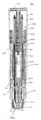
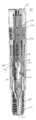
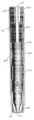
도1은 본 발명의 일 실시예에 따른 자동 주사기의 측단면도이다.1 is a side cross-sectional view of an autoinjector according to an embodiment of the present invention.
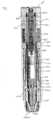
도2는 제 위치에 해제 핀을 갖는 비활성화 상태의 도1의 자동 주사기의 측단면도이다.Figure 2 is a side cross-sectional view of the autoinjector of Figure 1 in an inactive state with a release pin in place.
도3은 도2의 비활성화 상태의 자동 주사기의 개략적인 측면도이다.3 is a schematic side view of the autoinjector in an inactive state of FIG.
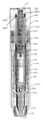
도4는 활성화를 위한 준비 시의 해제 핀이 제거된, 도1의 자동 주사기의 측단면도이다.4 is a side cross-sectional view of the autoinjector of FIG. 1 with the release pin removed in preparation for activation.
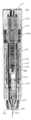
도5는 바늘 커버 스프링이 압축 상태에 있는, 도1의 자동 주사기의 측단면도이다.5 is a side cross-sectional view of the autoinjector of FIG. 1, with the needle cover spring in a compressed state.
도6은 도5의 자동 주사기의 개략적인 측면도이다.Figure 6 is a schematic side view of the autoinjector of Figure 5;
도7은 바늘이 약물 송달 위치에 있는 구동 상태의 자동 주사기의 측단면도이다.Fig. 7 is a side sectional view of the autoinjector in the driven state with the needle in the drug delivery position.
도8은 도7의 자동 주사기의 개략적인 측면도이다.8 is a schematic side view of the autoinjector of FIG.
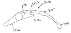
도9는 바늘 커버가 연장 보호 상태에 있는, 약물의 송달에 뒤이은 자동 주사기의 측단면도이다.9 is a side cross-sectional view of the autoinjector following delivery of the drug, with the needle cover in an extended protective state.
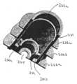
도10은 도9 및 도11에 도시된 바와 같이, 바늘 커버가 연장 보호 상태에 있을 때의 카트리지 용기의 로킹 날개의 확대도이다.Fig. 10 is an enlarged view of the locking vane of the cartridge container when the needle cover is in the extended protective state, as shown in Figs. 9 and 11;
도11은 도9의 자동 주사기의 개략적인 측면도이다.Figure 11 is a schematic side view of the autoinjector of Figure 9;
도12는 바늘 커버가 자동 주사기의 활성화 이전의 후퇴 위치에 위치된, 외측 본체가 제거된 도1의 자동 주사기의 개략적인 좌측면도이다.12 is a schematic left side view of the autoinjector of FIG. 1 with the outer body removed with the needle cover in the retracted position prior to activation of the autoinjector.
도13은 카트리지 용기의 로킹 날개 및 로킹 치형부의 위치를 도시하는 도12의 확대도이다.Fig. 13 is an enlarged view of Fig. 12 showing the positions of the locking vanes and locking teeth of the cartridge container.
도14는 바늘 커버가 자동 주사기의 사용 후에 연장 보호 위치에 위치될 때의, 외측 본체가 제거된 도1의 자동 주사기의 개략적인 좌측면도이다.14 is a schematic left side view of the autoinjector of FIG. 1 with the outer body removed when the needle cover is in the extended protective position after use of the autoinjector.
도15는 카트리지 용기의 로킹 날개 및 로킹 치형부의 위치를 도시하는 도14의 확대도이다.Fig. 15 is an enlarged view of Fig. 14 showing the positions of the locking vanes and locking teeth of the cartridge container.
도16은 바늘 커버가 연장 보호 위치에 있을 때의 로킹 치형부의 위치를 도시하는 확대된 단면도이다.Figure 16 is an enlarged cross sectional view showing the position of the locking teeth when the needle cover is in the extended protective position.
도17은 본 발명에 따른 자동 주사기를 위한 동력 팩에 대한 동력 팩 외측 본체의 좌측 후방 사시도이다.Figure 17 is a left rear perspective view of the power pack outer body for the power pack for autoinjector according to the present invention.
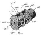
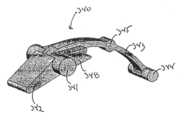
도18은 본 발명에 따른 자동 주사기를 위한 동력 팩에 대한 콜릿의 측면 사시도이다.18 is a side perspective view of a collet for a power pack for an autoinjector according to the present invention.
도19는 본 발명에 따른 자동 주사기를 위한 동력 팩에 대한 동력 팩 내측 본 체의 우측 전방 사시도이다.19 is a right front perspective view of the power pack inner body for the power pack for an autoinjector according to the present invention.
도20은 본 발명에 따른 자동 주사기를 위한 동력 팩에 대한 스프링 조립체의 측면 사시도이다.20 is a side perspective view of a spring assembly for a power pack for an autoinjector in accordance with the present invention.
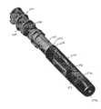
도21은 본 발명에 따른 자동 주사기를 위한 해제 핀의 좌측 저면 사시도이다.Figure 21 is a left bottom perspective view of the release pin for the autoinjector according to the present invention.
도22는 조립된 상태의 자동 주사기의 동력 팩의 우측 저면 사시도이다.Fig. 22 is a right bottom perspective view of the power pack of the autoinjector in the assembled state;
도23은 도22의 동력 팩의 측단면도이다.Figure 23 is a side sectional view of the power pack of Figure 22;
도24는 해제 핀의 상부 및 동력 팩 외측 본체의 주연 리브가 제거된, 도22의 동력 팩의 상부 좌측 사시도이다.24 is a top left perspective view of the power pack of FIG. 22 with the top of the release pin and peripheral ribs of the power pack outer body removed;
도25는 도22의 동력 팩의 상부 좌측 사시도이다.Figure 25 is a top left perspective view of the power pack of Figure 22;
도26은 안전 핀이 제거된, 외측 본체 내에 위치된 동력 팩의 상부 좌측 사시도이다.Figure 26 is a top left perspective view of a power pack located within the outer body with safety pins removed.
도27은 동력 팩 외측 본체의 좌측 측면 사시도이다.Figure 27 is a left side perspective view of the power pack outer body.
도28은 동력 팩 외측 본체의 내부를 도시하는 부분 단면 사시도이다.Fig. 28 is a partial sectional perspective view showing the inside of the power pack outer body.
도29는 동력 팩 내측 본체의 내부를 도시하는 부분 단면 사시도이다.Fig. 29 is a partial cross-sectional perspective view showing the inside of the power pack inner body.
도30은 동력 팩 내측 본체의 측면 사시도이다.30 is a side perspective view of the power pack inner body;
도31은 동력 팩 내측 본체의 저면 사시도이다.Fig. 31 is a bottom perspective view of the power pack inner body.
도32는 해제 핀의 측면도이다.32 is a side view of the release pin.
도33은 축에 대해 90° 회전된 도32의 해제 핀의 다른 측면도이다.FIG. 33 is another side view of the release pin of FIG. 32 rotated 90 ° about the axis.
도34는 도32의 안전 핀의 저면 사시도이다.Figure 34 is a bottom perspective view of the safety pin of Figure 32;
도35는 동력 팩의 콜릿의 측면도이다.35 is a side view of the collet of the power pack.
도36은 축에 대해 90° 회전된 도35의 콜릿의 다른 측면도이다.FIG. 36 is another side view of the collet of FIG. 35 rotated 90 ° about the axis.
도37은 안정화 아치를 도시하는 콜릿의 확대된 단부도이다.37 is an enlarged end view of the collet showing a stabilizing arch.
도38은 자동 주사기의 외측 본체 내에 위치된 바늘 커버의 측면 사시도이다.Figure 38 is a side perspective view of a needle cover located within the outer body of the autoinjector.
도39는 자동 주사기의 최종 조립 이전의 동력 팩이 제거된, 외측 본체 내에 위치된 카트리지 용기 및 바늘 커버의 단면도이다.Figure 39 is a cross sectional view of the cartridge container and needle cover located in the outer body with the power pack removed prior to final assembly of the autoinjector;
도40은 자동 주사기의 최종 조립 이전의 동력 팩이 제거된, 축에 대해 90° 회전된 도39의 외측 본체 내에 위치된 카트리지 용기 및 바늘 커버의 단면도이다.FIG. 40 is a cross sectional view of the cartridge container and needle cover located in the outer body of FIG. 39 rotated 90 ° about the axis with the power pack prior to final assembly of the autoinjector removed; FIG.
도41은 자동 주사기의 카트리지 용기의 전방 좌측 측면 사시도이다.Figure 41 is a front left side perspective view of a cartridge container of an autoinjector.
도42는 바늘 커버 스프링의 사시도이다.42 is a perspective view of a needle cover spring.
도43은 자동 주사기의 바늘 커버의 전방 좌측 측면 사시도이다.Figure 43 is a front left side perspective view of the needle cover of an autoinjector.
도44는 자동 주사기의 외측 본체의 전방 좌측 측면 사시도이다.Figure 44 is a front left side perspective view of the outer body of the autoinjector.
도45는 도44의 외측 본체의 다른 좌측 측면 사시도이다.Figure 45 is another left side perspective view of the outer body of Figure 44;
도46은 외측 본체의 내부를 도시하는 부분 단면 사시도이다.46 is a partial cross-sectional perspective view showing the inside of the outer body.
도47은 외측 본체의 측면도이다.Fig. 47 is a side view of the outer body.
도48은 축에 대해 90° 회전된 도47의 외측 본체의 다른 측면도이다.Figure 48 is another side view of the outer body of Figure 47 rotated 90 ° about the axis.
도49는 자동 주사기의 카트리지 용기의 우측 후방 측면 사시도이다.Figure 49 is a right rear side perspective view of the cartridge container of the autoinjector.
도50은 카트리지 용기의 측면도이다.50 is a side view of the cartridge container.
도51은 축에 대해 90° 회전된 도51의 카트리지 용기의 다른 측면도이다.Figure 51 is another side view of the cartridge container of Figure 51 rotated 90 ° about the axis.
도52는 점선이 로킹 날개의 변형 경로를 도시하는, 도51에 도시된 카트리지 용기의 확대된 측면도이다.Fig. 52 is an enlarged side view of the cartridge container shown in Fig. 51, with a dotted line showing the deformation path of the locking wing.
도53은 자동 주사기의 바늘 커버의 우측 후방 사시도이다.Fig. 53 is a right rear perspective view of the needle cover of the autoinjector.
도54는 도53의 바늘 커버의 측면도이다.Figure 54 is a side view of the needle cover of Figure 53;
도55는 바늘 커버 스프링의 사시도이다.55 is a perspective view of a needle cover spring.
도56은 본 발명에 따른 자동 주사기의 로킹 치형부의 우측 상부 사시도이다.Fig. 56 is a top right perspective view of a locking tooth of an autoinjector according to the present invention.
도57은 도55의 로킹 치형부의 좌측 저면 사시도이다.FIG. 57 is a left bottom perspective view of the locking teeth of FIG. 55; FIG.
도58은 로킹 치형부의 측면도이다.58 is a side view of the locking tooth.
도59는 로킹 치형부의 평면도이다.59 is a plan view of the locking teeth.
본원에서 설명되는 구성요소들 중 일부는 본원에서 전체적으로 참조된 미국 특허 제4,031,893호("'893 특허")에 설명된 바와 같이, 광범위한 태양에서 종래에 공지되었고, 따라서 여기서 불필요하게 상세히 설명되지 않는다는 것이 이해되어야 한다. '893 특허에 대한 공지된 변형 또는 변경이 후술하는 바와 같이 본 발명의 자동 주사기에 동등하게 적용될 수 있다는 것도 이해되어야 한다. 이러한 변형 또는 변경은 미국 특허 제4,226,235호, 제4,329,988호, 제4,394,863호, 제4,723,937호, 미국 특허 출원 제09/985,466호, 제10/285,692호에 설명된 실시예를 포함하고, 이들 각각은 그의 전체적인 내용에 대해 전체적으로 참조되었다.It is understood that some of the components described herein are conventionally known in a wide variety of aspects, as described in US Pat. No. 4,031,893 ("'893 Patent"), which is incorporated herein by reference in its entirety, and therefore is not described in detail unnecessarily herein. It must be understood. It should also be understood that known variations or modifications to the '893 patent may be equally applicable to the autoinjector of the present invention as described below. Such variations or modifications include the embodiments described in US Pat. Nos. 4,226,235, 4,329,988, 4,394,863, 4,723,937, US Patent Application Nos. 09 / 985,466, 10 / 285,692, each of which Full reference is made to the full text.
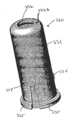
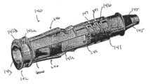
본 발명의 자동 주사기(100)가 이제 도1 - 도59와 관련하여 더욱 상세하게 설명될 것이다. 자동 주사기(100)는 외측 본체(110), 해제 핀(120), 동력 팩(130), 카트리지 용기(140), 바늘 커버(150) 및 일정 용량의 약품을 담는 카트리 지(160)를 포함한다. 용량은 액체 또는 고체 형태로 또는 주사 이전에 혼합되는 액체 및 고체의 조합으로서 저장될 수 있다.The
자동 주사기(100)는 도38 및 도44 - 도48에 도시된 외측 본체(110)를 포함한다. 외측 본체(110)는 원통형 본체에 비해 사용자 또는 보호자에 의한 용이한 파지 및 사용을 허용하는 더욱 인간 공학적인 크기의 대체로 난형 또는 타원형 형상을 갖는다. 외측 본체(110)의 대체로 난형 형상은 자동 주사기(100)가 편평 표면에서 우발적으로 구르거나 미끄러지는 것을 방지한다. 또한, 난형 형상은 자동 주사기(100)에 설명서를 라벨링하기 위한 더 큰 인쇄 표면을 제공한다. 외측 본체(110)는 양호하게는 쉽게 성형될 수 있도록 합성 재료로부터 형성된다. 외측 본체(110)는 투명할 수 있어서, 내부 구성요소가 외측 본체(110)를 통해 쉽게 보일 수 있. 그러한 구성에서, 사용자는 소정 시점에서 카트리지 용기(140) 및 바늘 커버(150) 내의 창(141a, 141b)을 통해 카트리지(160)의 내용물을 관찰할 수 있다. 외측 본체(110)는 내부 구성요소가 외측 본체(110)를 통해 보이지 않도록 불투명할 수 있는 것도 고려된다. 외측 본체(110)는 외측 본체(110) 내의 구성요소의 관찰을 허용하는 창 또는 창들을 갖는 것도 고려된다. 외측 본체(110)는 해제 핀(120)을 수납하는 크기의 일 단부 내에 형성된 개방부(111)를 갖는다. 제 위치에 있을 때, 해제 핀(120)은 자동 주사기(100)의 우발적인 사용 또는 활성화를 방지한다. 해제 핀(120)은 도32 - 도34에 도시되어 있다. 사용 설명서가 외측 본체(110) 상으로 직접 인쇄될 수 있는 것이 고려된다. 라벨이 외측 본체(110)에 부착될 수 있는 것도 고려되고, 이는 외측 본체(110)의 강성을 증가시킬 수 있다. 외측 본 체(110)가 하나 이상의 개구를 포함할 때, 라벨의 제공은 외측 본체(10)의 강도를 증가시키고, 이는 추가의 구조적 보강을 필요 없게 만든다.The
개방부(111)는 도45, 도46 및 도48에 도시된, 외측 본체(11)의 대향 측면들을 따라 하방으로 연장되는 측면 리세스(111a, 111b)를 포함한다. 2개의 리세스가 도시되어 있지만, 단일 리세스가 제공될 수 있거나, 둘 이상이 제공될 수 있는 것이 고려된다. 리세스의 개수는 탭의 개수에 대응할 것이다. 리세스(111a, 111b)는 하방 연장 탭(121a, 121b)을 해제 핀(120) 상에 수납할 수 있는 크기이다. 탭(121a, 121b)은 해제 핀(120)의 회전을 방지하여, 사용자는 자동 주사기(100)를 구동하도록 해제 핀(120)을 제거하기 위해, 해제 핀(120)이 회전되기 보다는 당겨져야 한다는 것을 쉽게 인식한다. 탭(121a, 121b)은 주로 상세하게 후술되는 동력 팩(130)의 대향 측면들 상에 위치된 보유 리세스(235) 내에 수납된다. 리세스(111a, 111b)는 리세스(235) 내의 탭(121)에 대한 접근을 제공한다. 탭(121a, 121b)은 우발적인 제거를 방지하기 위해 동력 팩(130) 상으로 압축 끼워 맞춤된다. 핀(120)을 해제하기 위해, 작업자는 탭(121)의 모서리를 리세스(235)로부터 이탈시키도록 탭(121)을 압축하거나 조이고, 그 다음 핀(120)이 동력 팩(130)으로부터 당겨지고/제거될 수 있다. 도시된 바와 같이, 탭(121)은 리세스(235)의 모서리와 맞물리는 모따기된 모서리를 생성하는 곡률을 갖는다. 탭(121) 및 리세스(235)의 형상은 완전히 상보적이며, 이는 핀(120)과 동력 팩(130) 사이에 마찰 또는 압축 보유력을 생성한다. 해제 핀(120)은 또한 동력 팩(130)의 상부 표면 상에 수납되도록 적응된, 하방 돌출 리브(122a, 122b)를 포함한다. 리브(122a, 122b)는 해제 핀(120)의 안정성 및 강성을 증가시킨다. 추가의 리브가 제공될 수 있는 것이 고려된다. 해제 핀(120)은 주연 레지(124)를 갖는 외측으로 향하는 편평 단부(123)를 포함한다. 주연 레지(124)는 사용자에 의한 해제 핀(120)의 파지를 허용한다. 레지(124)는 개방부(111)에 인접한 외측 본체(110)의 단부 표면 상에 놓이는 크기이다. 해제 핀(120)은 동력 팩(130)의 콜릿(430)과 맞물리는 하방 연장 핀(125)을 포함한다. 제 위치에 고정되었을 때 (즉, 해제 핀(120)의 제거 이전에 그리고 자동 주사기(100)의 구동 이전에), 핀(125)은 콜릿(430)의 단부가 압축되는 것을 방지하고, 이는 자동 주사기(100)의 구동을 방지한다. 단부(123)는 외측 본체(110)의 난형/타원형 형상에 대응하는 형상을 갖는다.The
도46에 도시된 바와 같이, 외측 본체(110)의 내측 표면은 동력 팩(130), 카트리지 용기(140) 및 바늘 커버(150)를 내부에 수납하는 형상이다. 많은 종래 기술의 바늘 커버와 달리, 바늘 커버(150)는 용기(140)와 외측 본체(110) 사이에 위치되어, 사용자는 작동 중에 커버의 전개를 방해하거나 카트리지 내의 다이어프램이 조기에 파열되게 할 수 있는 커버(150)와의 접촉을 하지 않는다. 추가적으로, 커버 부재를 로킹시키고 전개하기 위한 메커니즘은 외측 본체(110) 내에 위치되고, 따라서 훼손 및 먼지 유입에 대해 보호된다. 외측 본체(110)는 개방부(111)에 인접한 외측 본체(110)의 단부 근방의 내측 표면 상에 형성된 카트리지 용기 보유 단차부(112)를 포함한다. 카트리지 용기(140)의 레지(142)는 자동 주사기(100)가 조립되면 외측 본체(110) 내에서의 카트리지 용기(140)의 하방 이동을 제한하도록 보유 단차부(112)와 맞닿아서, 용기가 개방부(114)로부터 이동될 수 없다. 복수의 동력 팩 보유 개방부(113a, 113b, 113c)가 외측 본체(110)의 적어도 하나의 측면 상에 형성된다. 동력 팩(130) 상의 돌출부 또는 치형부(238)가 개방부(113) 내로 스냅 결합된다. 이러한 스냅 결합은 외측 본체(110) 내에 설치되었을 때, 외측 본체(110)로부터의 동력 팩(130)의 제거를 방지한다. 동력 팩 외측 본체(230)는 외측 본체(110)에 대해 이동할 수 없다. 카트리지 용기(140)의 레지(142)는 보유 단차부(112)와 동력 팩(130) 사이에 삽입된다.As shown in FIG. 46, the inner surface of the
개방부(114)가 개방부(111)에 대향한 단부 상에서 외측 본체(110) 내에 형성된다. 개방부(114)는 카트리지 용기(140)의 일부분 및 바늘 커버(150)의 일부분이 그로부터 연장될 수 있도록 구성된다. 단차부(112)는 개방부(114)를 통한 용기(140)의 이동을 제한한다. 외측 본체(110)의 단부는 커버(100)의 단부가 주사 표면과 접촉하도록, 사용자의 주사 표면에 인접하게 배치되도록 의도된다.An
동력 팩(130)이 이제 도17 - 도20, 도22 - 도31 및 도35 - 도37과 관련하여 상세하게 설명될 것이다. 동력 팩(130)은 동력 팩 외측 본체(230), 동력 팩 내측 본체(330), 콜릿(430) 및 동력 팩 스프링 조립체(530)를 포함한다. 동력 팩 내에 저장된 에너지를 방출하는데 필요한 활성화력은 4 내지 8 파운드 사이이다. 활성화력은 자동 주사기(100)가 주사 표면에 대해 가압될 때, 내측 본체(330)로부터 콜릿(43)을 해제하기 위해 요구되는 힘이다. 스프링 조립체(530)에 의해 제공되는 주입력은 대략 30 파운드이다. 주입력은 카트리지(160)가 카트리지 용기(140) 내에서 전진되어 사용자 내로의 약품의 주사를 허용하기 위해 바늘이 외피를 관통하도록 바늘을 구동하기에 충분해야 한다. 동력 팩 외측 본체(230)는 대체로 원통형 인 신장된 중공 본체(231)이다. 복수의 외측 주연 리브(232a, 232b, 232c)가 중공 본체(231)의 외측 표면으로부터 외측으로 연장된다. 이러한 리브(232)가 도시되어 있지만, 추가의 리브가 제공될 수 있는 것이 고려된다. 리브(232)는 자동 주사기(100)의 외측 본체(110)의 뒤틀림을 방지하도록 제공된다. 복수의 외측 종방향 리브(233a, 233b)가 중공 본체(231)의 외측 표면 둘레에서 이격된다. 리브(233)는 리브(232)와 협동하여, 자동 주사기(100)를 더욱 강화하고, 사용자에 의해 파지되어 사용될 때 외측 본체(110)의 뒤틀림을 방지한다.The
주연 리브들 중 하나(232a)는 동력 팩 외측 본체(230)의 상단부 표면(237)을 형성한다. 해제 핀(120)의 하방 연장 핀(125)을 수납하는 크기의 구멍(234)이 단부 표면 내에 제공된다. 보유 리세스(235a, 235b)가 상단부 표면에 인접한 중공 본체(231)의 대향 측면들 상에 형성된다. 리세스(235a, 235b)는 중공 본체(231)로부터 외측으로 그리고 주연 리브(232a)의 상단부 표면(237)으로부터 상방으로 연장되는 벽(236a, 236b)에 의해 형성된다. 리세스(235a, 235b)는 해제 핀(120)이 자동 주사기(100)에 고정될 때, 탭(121a, 121b)이 리세스(235a, 235b) 내에 수납되도록, 외측 본체(110)의 측면 리세스(111a, 111b)와 정렬된다. 리세스(235a, 235b)는 해제 핀(120)을 우발적인 제거를 방지하도록 제 위치에 고정시키기 위해 탭(121a, 121b) 상에 압축력을 인가하는 크기이다.One of the
도17, 도26 및 도27에 도시된 바와 같이, 벽(236a, 236b)은 주연 리브(232a)의 단부 표면(237)으로부터 상방으로 연장된다. 그러한 배열에서, 단부 표면(237)은 도26에 도시된 바와 같이, 외측 본체(110)의 단부 표면 아래에서 이격되거나 리 세스되어, 리세스(115)를 형성한다. 리세스(115)는 푸시 버튼의 시각적 효과를 감소시키고 그리고/또는 방지한다. 이와 같이, 사용자는 약품을 투여하기 위해 단부 표면(237)을 누르는 경향을 갖지 않을 것이다. 추가적으로, 이는 리세스(115)가 자동 주사기(100)의 비작동 단부에 위치되었다는 시각적 표시를 사용자에게 제공하여, 사용자는 커버(150)를 자동 주사기의 대향 단부가 아닌 주사기 표면에 대해 위치시키는 경향이 있다. 리세스(115)는 또한 구멍(234)의 존재를 강조하지 않도록 구멍(234)을 자동 주사기(100)의 단부로부터 이격시키도록 역할하여, 사용자가 외측 본체(110) 상의 라벨을 읽을 때, 구멍이 숨겨진다. 이와 같이, 사용자는 구멍(234)을 주사 부위에 인접하게 위치시키는 경향이 없다. 이러한 배열은 자동 주사기(100)의 부적절한 사용을 방지하도록 제공된 단 한 가지 대책이다. 해제 핀(120)의 리브(122a, 122b)는 리세스(115) 내에 수납된다.As shown in Figures 17, 26 and 27, the walls 236a and 236b extend upwards from the
복수의 돌출부 또는 치형부(238a, 238b, 238c)가 중공 본체(231)의 외측 표면 상에 형성된다. 치형부(238a, 238b, 238c)는 동력 팩(130)을 외측 본체(110) 내에 고정시키기 위해 개방부(113a, 113b, 113c) 내로 스냅 결합되는 크기이다. 이러한 구성은 이러한 구성요소(110, 130)가 다른 결합 형태의 접착이 필요 없이 서로 고정되도록 허용한다. 대응하는 치형부(238) 세트가 외측 본체(110) 내의 대응하는 개방부와 정합되도록 중공 본체(230)의 대향 측면 상에 제공될 수 있다.A plurality of protrusions or teeth 238a, 238b, 238c are formed on the outer surface of the
중공 본체(231)의 내부는 동력 팩 내측 본체(330) 상의 보유 탭(334)을 수납하는 크기의 리세스(231a)를 포함한다. 리세스(231a)는 중공 본체(231)의 내측 주연부 둘레에서 연장되는 홈일 수 있다. 리세스(231a)는 단부 표면(237)에 대향한 단부 근방에서 중곤 본체(231) 내에 위치된다. 도1 및 도28에 도시된 바와 같이, 콜릿 활성화 구조물(239)이 단부 표면(237)의 내측 측면으로부터 중공 본체(231)의 내부 내로 연장된다. 콜릿 활성화 구조물(239)은 자유 단부 상에 위치된 경사진 콜릿 활성화 표면(239a)을 갖는 대체로 원통형 형상을 갖는다. 활성화 표면(239a)은 핀(120)이 제거되고 주사기의 전방 단부가 주사 부위 내로 가압되어, 카트리지 용기(140)가 후방으로 이동하여 내측 본체(330)와 맞물릴 때, 스프링 조립체(530)를 해제하고 사용자에게 약품을 주사하는데 필요한 에너지를 방출하도록 콜릿(430)의 화살촉부(434)들을 함께 이동시키기 위해, 화살촉부(434) 및 특히 그의 후방 표면(489; 도35 참조)을 표면(239a)과 맞물리도록 후방으로 이동시키도록, 제공된다. 리브(239b)는 콜릿 활성화 구조물(239)을 보강하도록 제공될 수 있다. 콜릿(430)을 해제하는 다른 수단이 채용될 수 있는 것이 고려된다. 푸시 버튼형 구동 배열이 채용될 수 있고, 이는 미국 특허 제4,031,893호에 상세하게 설명되어 있으며 본원에서 전체적으로 참조되었다.The interior of the
동력 팩 내측 본체(330)는 대체로 원통형인 중공 내측 본체(331)이다. 중공 내측 본체(331)는 일 단부 내에 형성된 개방부(332)를 갖는다. 개방부(332)는 동력 팩 내측 본체(330) 내에 적절하게 장착될 수 있도록 자동 주사기(100)의 조립 중에 콜릿 조립체(430)의 일부분을 압축하도록 사용되는 콜릿 조립체 인입 표면(332a)을 갖는다. 개방부(332)는 또한 활성화 이전에 콜릿(430)의 대향 화살촉부(434)를 지지하는 대향 모서리 상에 위치된 콜릿 보유 표면(332b)을 갖는다. 중공 내측 본체(331)는 대향 단부 상에 형성된 개방부(333)를 갖는다. 보유 리세 스(231a) 내에 스냅 결합되는 크기의 복수의 보유 탭(334)이 개방부(333)로부터 이격된다. 리세스(231) 및 탭(334)은 동력 팩 내측 본체(330)와 동력 팩 외측 본체(230) 사이의 제한된 이동을 허용한다. 배열은 또한 자동 주사기(100)를 조립할 목적에 대해 유익하다. 내측 본체(330) 및 외측 본체(230)는 미리 조립될 수 있다. 리세스(231) 및 탭(334)은 내측 본체(230) 및 외측 본체(330)를 조립을 위해 적절하게 정렬되도록 유지한다. 또한, 배열은 내측 본체(330) 및 외측 본체(230)의 하위 조립체가 자동 주사기(100)의 최종 조립 이전에 분리되는 것을 방지한다. 구성요소들을 서로 고정시키는, 외측 동력 팩과 내측 동력 팩 사이의 제한된 이동을 허용하는 다른 수단이 채용될 수 있는 것도 고려된다. 레지(335)가 개방부(333)의 주연부 둘레에서 적어도 부분적으로 연장된다. 레지(335)는 상세하게 후술하는 바와 같이, 자동 주사기(100)의 작동 중의 특정 시점에서 카트리지 용기(140) 및 동력 팩 외측 본체(230)와 맞물리는 크기이다. 동력 팩 및 스프링(530) 상에 영구적으로 힘을 가하는 것을 방지하는 갭을 생성하기 위해 자동 주사기(100)의 조립 이후 및 활성화 이전에 내측 동력 팩(330)과 카트리지 용기(140) 사이에 간격이 존재한다.The power pack
콜릿(430)이 동력 팩 내측 본체(330)의 중공 내부 내에 수납된다. 콜릿(430)은 양호하게는 성형된 단일편 구성이다. 콜릿(430)은 한 쌍의 측면 아암(433a, 433b)을 형성하는, 내부에 형성된 개방부(432)를 갖는 신장된 본체(431)이다. 각각의 측면 아암(433a, 433b)은 각각 화살촉 세부(434a, 434b)를 포함한다. 각각의 화살촉부(434a, 434b)의 일 측면은 콜릿 보유 표면(332b)과 접촉하여 맞물리도록 구성된다. 각각의 화살촉부(434a, 434b)의 대향 측면은 측면 아암(433a, 433b)이 자동 주사기(100)의 작동을 허용하도록 내측으로 변형되게 하는 콜릿 조립체 인입 표면(332a)과 맞물리도록 구성된다. 화살촉부(434a, 434b)에 인접한 콜릿(430)의 단부(435)는 해제 핀(120)의 핀(125)을 수납하는 크기의 개방부(435a)를 포함한다. 핀(125)은 측면 아암(433)들이 서로를 향해 내측으로 변형되는 것을 방지한다. 제 위치에 고정되었을 때, 핀(125)은 자동 주사기(100)의 활성화를 방지한다. 개방부(432)는 도37에 도시된 바와 같이, 일 단부 상에 형성된 아치(432a)를 갖는다. 아치(432a)는 측면 아암(433)을 안정화하는 것을 돕고, 아암들이 서로 압축되었을 때 이들이 멀리 튀는 것을 보조한다. 아치(432a)는 콜릿 상의 응력의 양을 감소시킨다.The
콜릿(430)은 동력 팩 스프링 조립체(530) 내에 위치된다. 스프링 조립체(530)의 일 단부는 콜릿(430) 상에 형성된 플랜지(436) 상에 지지된다. 플랜지(436)는 신장된 본체(431)로부터 외측으로 연장된다. 플랜지(436)가 스프링 조립체(530)의 일 단부를 지지하지만, 본체(431) 상에서의 플랜지(436)의 배치는 또한 사용자에게 주사되는 약품의 송달 용량 체적을 한정하도록 역할할 수 있다. 몇몇 용도에서, 약품의 일부가 카트리지(160) 내에 남도록 바늘을 통해 송달되는 약품의 양을 제어하는 것이 바람직하다. 플랜지(436)는 콜릿(430)이 액체 약품을 담는 카트리지(160) 내로 이동할 수 있는 거리를 제한할 수 있다. 이와 같이, 송달되는 약품의 양이 제어된다. 이러한 배열에서, 플랜지(436)는 카트리지(160)의 단부와 접촉하는 크기이다. 대경 카트리지 및 대용량의 약품에 대해, 플랜지(436)가 카트리지(160) 내에서 이동할 수 있는 것이 고려된다. 콜릿(430)은 플런저(438)를 수납하는 돌출부(437)를 더 포함한다. 플런저(438)는 카트리지(160) 내에 활주 가능하게 수납된다. 다른 용도에서, 카트리지(160)로부터 약품의 전부를 분배하는 것이 바람직하다. 소량의 약품 잔량이 바늘(162) 및 바늘(162)에 인접한 카트리지(160)의 목부 내에 남는다. 이러한 용도에서, 플랜지(436)는 플런저(438)가 바늘(162)을 통해 (전술한 잔량을 제외하고는) 약품의 전부를 분배하도록 카트리지(160)의 내부의 길이를 이동하도록 카트리지(160)의 내부 내에서 이동한다. 상이한 크기의 콜릿(430)이 본 자동 주사기(100) 내에서 사용될 수 있는 것이 고려된다. 이와 같이, 콜릿(430)은 카트리지 크기 및 원하는 용량에 기초하여 변화될 수 있다.
콜릿(430)은 양호하게는 적합한 플라스틱 재료로부터 단일편으로서 형성된다. 단일편 콜릿(430)은 콜릿을 형성하는데 필요한 부품의 개수를 감소시킴으로써, 제조를 단순화하고 비용을 절감한다. 또한, 다른 자동 주사기 내에서, 스페이서가 상이한 자동 주사기에 대해 상이한 양의 약품을 수용하기 위해 콜릿(430)과 관련하여 사용되도록 요구되었다. 본 발명에 따른 콜릿(430)은 다부품 구성과, 또한 유리하게는 스페이서에 대한 필요성을 제거한다. 콜릿의 길이는 원하는 분량에 기초하여 선택될 수 있다. 이러한 구성은 또한 플런저 및 동력 팩 내측 본체 위의 발사 시트 내에서 전형적으로 발견되는 금속 삽입물을 제거한다. 콜릿(430) 자체의 크기 및 형상이 상이한 크기의 카트리지(160)를 수용하기 위해 변경될 수 있는 것이 고려된다. 플랜지(436)가 카트리지(160)와 접촉하지 않을 때, 바늘 또는 카 트리지(160)의 목부 내에 남는 잔량을 제외하고는 카트리지(160)의 전체 내용물을 분배하는 것이 가능하다. 본원에서 전체적으로 참조된 윌모트의 미국 특허 제5,713,866호에 개시된 바와 같은 니플 플런저가 카트리지(160)의 목부 내에서의 약품 잔량의 축적을 방지하도록 채용될 수 있는 것이 고려된다. 플랜지(436)의 위치는 플랜지(436)가 카트리지(160)와 접촉하기 전에 콜릿 및 플런저(438)가 카트리지(160) 내에서 더 큰 용량이 분배되는 더 큰 거리를 이동하도록 플랜지가 위치될 때, 사용자 내로 주사되는 분량을 제어하도록 변경될 수 있다. 콜릿(430)의 길이 및 카트리지(160)의 직경은 원하는 유량이 얻어지도록 카트리지(160)의 바늘(162)을 통한 유체의 유동을 제어하도록 선택될 수 있다. 본 발명에 따른 자동 주사기(100)는 가변 크기의 콜릿(430)이 동일한 외측 본체(110) 및 동력 팩(430) 내에서 사용될 수 있도록 구성된다.The
스프링 조립체(530)의 대향 단부가 개방부(332)에 대한 동력 팩 내측 본체(330)의 내측 표면에 대해 놓인다.Opposite ends of the
카트리지 용기(140)가 이제 도41 및 도49 - 도52와 관련하여 상세하게 설명될 것이다. 카트리지 용기(140)는 외측 본체(110) 내에 수납되는 크기의 대체로 신장된 중공 본체(141)를 갖는다. 레지(142)가 신장된 본체(141)의 일 단부 상에 형성된다. 레지(142)는 외측 본체(110)의 내측 표면 상에 형성된 보유 단차부(112)와 접촉한다. 레지(142)는 카트리지 용기가 개방부(114)를 통해 제거될 수 없도록, 외측 본체(110) 내에서의 카트리지 용기(140)의 하방 이동을 제한한다. 레지(142)는 동력 팩 외측 본체(230) 상의 리브(232a, 232b, 232c)와 유사하게 외 측으로 연장되는 주연 리브(142a, 142b)에 의해 형성된다. 리브(142a, 142b)는 또한 외측 본체(110)의 뒤틀림을 방지한다.The
신장된 중공 본체(141)는 내부에 카트리지(160)를 수납하는 크기의 중공 내부를 갖는다. 중공 본체는 카트리지(160)가 중공 내부 내에 위치될 수 있도록 그리고 콜릿(430)이 카트리지(160) 내에 활주 가능하게 수납되는 것을 허용하도록, 개방부(143)를 갖는다. 카트리지 용기(140) 및 그의 로킹 치형부(340)는 완전한 바늘 커버 기능성을 유지하면서, 다양한 크기의 카트리지(160)를 수용하도록 설계된다. 이와 같이, (카트리지 용기 및 로킹 치형부를 포함하는) 일반적인 설계의 바늘 커버 조립체는 다양한 상이한 체적의 약물 및 상이한 크기의 바늘에 대해 사용될 수 있다. 더 길고 더 큰 카트리지에 대해, 카트리지(160)를 손상 또는 파단시킬 수 있는 축방향 및 반경방향 이동을 방지하기 위해 추가의 지지부를 제공하는 것이 바람직하다. 한 쌍의 탭(600)이 중공 본체(141) 상에 형성되어, 그러한 축방향 및 반경방향 이동을 방지하기 위해 카트리지(160)를 적절한 배향으로 유지하고 정렬하도록 카트리지(160) 상에 압축력을 인가한다. 탭(600)은 카트리지가 약품 분배 시퀀스 이전에 카트리지 홀더(140)와 함께 전방으로 이탈되거나 이동되는 것을 방지하기 위해, 충격 부하 중에 중공 본체(141) 내의 카트리지(160)의 이동을 방지하기 위한 기능을 제공한다. 전형적으로, 더 작은 카트리지는 탭(600)과 접촉하지 않는다. 콜릿(430) 및 바늘 및 바늘 외피는 카트리지에 대한 충분한 지지를 제공한다. 중공 본체(141)의 단부는 바늘(162) 및 카트리지(160)의 보호 외피(165)의 통과를 허용하는 크기의 개방부(144)를 갖는 테이퍼진 구성을 갖는다. 복수의 리브(145)가 테이퍼진 단부 상의 중공 본체(141)의 외측 표면 상에 형성된다. 리브(145)는 바늘 커버(150)의 바늘 커버 스프링(153)을 안정화하는 것을 돕는다. 리브(145)는 또한 자동 주사기(100)의 조립을 보조하는 가이드로서 역할한다.The elongated
신장된 중공 본체(141)는 내부에 형성된 적어도 하나의 관찰 창(141a, 141b)을 갖는다. 관찰 창(141a, 141b)은 자동 주사기(100)의 활성화 이전에, 약품이 오염되거나 배출되지 않도록 보장하기 위해, 카트리지(160)의 내용물을 관찰하도록 허용한다.The elongated
한 쌍의 로킹 아암 또는 날개(240)가 도52에 도시된 바와 같이, 레지(142)로부터 연장되어 중공 본체(141)의 중간 부분에 연결된다. 각각의 로킹 날개(240)는 도52에 도시된 바와 같이, 대체로 만곡된 형상을 갖는 두꺼운 스트럿(241)을 갖는다. 두꺼운 스트럿(241)은 압축 하중이 로킹 날개(240)에 인가될 때 (즉, 사용자가 자동 주사기(100)의 사용 후에 바늘 커버(150)를 다시 외측 본체(110) 내로 밀어 넣기를 시도할 때), 두꺼운 스트럿(241)이 도52에서 점선에 의해 도시된 방식으로 구부러지도록 만곡된다. 그러한 구성에서, 로킹 날개(240)는 카트리지 용기(140)의 본체(141)에 의해 지지되고, 이는 로킹 날개(240)의 압축 강도를 증가시킨다. 양호하지는 않지만, 단일 로킹 날개(240)가 제공될 수 있는 것이 고려된다.A pair of locking arms or
얇은 스트럿(242)이 스트럿(241)의 자유 단부로부터 연장되어 카트리지 용기(240)의 본체(141)에 연결된다. 로킹 표면(243)이 스트럿(241, 242)들의 교차부에 형성된다. 로킹 표면(243)은 도9 및 도10에 도시된 도시된 바와 같이, 자동 주 사기(100)의 작동 후에 커버(150) 상의 표면과 맞물려서 커버(150)의 내측 이동을 제한한다. 얇은 스트럿(242)은 두꺼운 스트럿(241)이 외측 방향으로 편위되도록 유지하기 위한 스프링력을 제공한다. 얇은 스트럿(242)은 또한 극심한 하중 하에서 인장 강도를 제공하고, 스트럿(241)이 측면 방향으로 좌굴되는 것을 방지하는 것을 돕고, 이는 얇은 스트럿(242)이 커버 부재(150)가 연장 위치로 이동된 후에, 바늘 커버(150) 내의 안내 홈 내에 유지되어 남기 때문이다. 스트럿(242)의 만곡된 형상은 도52에서 점선으로 도시된 바와 같이 스트럿(242)이 내측으로 구부러지도록 허용한다. 이는 전체 날개(240)가 강성 아치를 형성하는 것을 방지하고, 따라서 날개(240)를 따라 과도한 압축 하중을 발생시키지 않고서 두꺼운 스트럿(241)이 본체(141)를 향해 내측으로 휘어지도록 허용한다.A
도39, 도41, 도49, 도50 및 도52에 도시된 바와 같이, 카트리지 용기(140)의 신장된 본체(141)는 얇은 스트럿(242) 사이에 위치된 리세스(244)를 포함한다. 로킹 아암(240)이 외측 본체(110) 상에 위치되면, 리세스(244)는 외측 본체(110) 내에 형성될 수 있다. 대안적으로, 외측 본체(110) 내의 개방부가 또한 제공될 수 있다. 이러한 리세스(244)는 얇은 스트럿(242)이 본체(141)를 향해 내측으로 이동하는 거리를 증가시키고, 이는 스트럿(241)을 외측으로 편위된 위치에 유지하기 위해 제공되는 스프링력을 증가시킨다. 로킹 날개(240)는 평시에 무응력 상태로 유지된다. 로킹 날개(240)는 바늘 커버(150)가 그 위를 통과할 때 일시적으로 압축된다. 로킹 날개(240)는 도10에 도시된 바와 같이, 로킹 표면(243)이 커버 부재(150)와 맞물리도록 튀어 나와서, 바늘 커버(150)가 후방으로 밀리는 것을 방지 한다.39, 41, 49, 50, and 52, the
신장된 슬롯(146)이 신장된 본체(141)의 각각의 측면 상에 형성된다. 슬롯(146)은 도49 및 도51에 도시된 바와 같이, 스트럿(242)의 단부로부터 연장된다. 각각의 슬롯(146)은 로킹 치형부(340)를 수납하는 크기이다. 도1, 도2, 도4, 도5, 도7, 도9, 도16, 도39 및 도41에 도시된 바와 같이, 로킹 치형부(340)는 카트리지 용기(140)의 대향 측면들 상에 로킹된다. 로킹 치형부(340)는 자동 주사기(100)의 작동 이후까지 바늘 커버(150)가 전개되는 것을 억제하도록 제공된다. 한 쌍의 로킹 치형부(340)가 제공된다. 양호하지는 않지만, 단일 로킹 치형부(340)가 채용될 수 있는 것이 고려된다.An elongated slot 146 is formed on each side of the
각각의 로킹 치형부(340)는 축 슬롯(147) 내의 베어링 축(341)에 대해 피벗할 수 있다. 복수의 축 슬롯이 치형부(340)의 위치가 조정될 수 있도록 제공될 수 있다. 도56 - 도59에 도시된 바와 같이, 각각의 로킹 치형부(340)는 베어링 표면(342a)을 갖는 탭(342)을 갖는다. 탭(342)은 신장된 본체(141)의 내부 내로 연장되어 카트리지(160)와 접촉할 수 있도록 슬롯(146) 내에 위치된다. 카트리지(160)가 자동 주사기(100)의 작동 중에 본체(141) 내에서 전진되므로, 카트리지(160)와 베어링 표면(342a) 사이의 접촉은 로킹 치형부(340)가 축(341)에 대해 회전하게 한다. 표면(342a)이 카트리지(160)와 접촉하는 동안, 로킹 치형부(340)는 주사 작동 중에 용기(140) 내에서의 카트리지(160)의 이동에 대해 최소의 또는 무시할 수 있는 영향을 갖는다. 로킹 치형부에 의해 카트리지에 인가되는 낮은 또는 최소의 힘은 바늘이 완전히 연장되기 전에 다이어프램을 조기 파열시킬 수 있는 카트리지 내의 압력 축적을 일으키지 않는 점에서 유리하다. 또한, 용기(140) 내에서의 카트리지(140)의 이동은 로킹 치형부(340)에 의해 방해받지 않거나 무시할 수 있게 방해받는다. 탭(342)은 축(341)의 일 측면으로부터 연장된다. 스프링 미부(343)가 축(341)의 대향 측면으로부터 연장된다. 스프링 미부(343)는 슬롯(146) 내에 위치되고, 카트리지 용기(140)를 따라 활주하도록 설계된다. 스프링 미부(343)는 바늘 커버(150)가 자동 주사기(100)의 작동 이전에 후퇴 위치에 보유되거나 로킹되도록, 로킹 치형부(340)를 로킹 위치로 편위시키도록 역할한다. 스프링 미부(343)가 스프링 조립체로 대체될 수 있는 것이 고려된다. 베어링 표면(344)이 미부(343)의 일 단부 상에 제공되어, 스프링 미부(343)가 슬롯(146) 내에서 카트리지 용기(140)를 따라 매끄럽게 활주하도록 허용한다. 베어링 표면(344) 및 중심 본체(345)는 배출기 핀을 위한 편평 영역을 제공한다.Each locking
v-형 노치(347)가 스프링 미부(343) 아래에 형성된다. 노치(347)는 자동 주사기(100)의 작동 이전에 바늘 커버(150)를 유지하는 일 측면 상의 로킹 표면(347a)을 갖는다. 다른 표면(347b)은 카트리지 용기(140) 내에서의 치형부(340)의 이동을 제한하여 그의 회전을 제한한다. 노치(347)는 스프링 미부(343)의 각 측면 상에서 연장되는 탭(348)의 일부로서 형성된다. 로킹 치형부(340)는 자동 주사기(100)의 유연성을 증가시킨다. 다양한 길이 및 직경의 많은 카트리지가 자동 주사기(100)를 변형시키지 않고서 사용될 수 있다. 미부(343)의 스프링 작용은 표면(342a)이 카트리지(160)와 접촉하도록 로킹 치형부(340)의 위치를 조정한다.A v-shaped
카트리지 용기(140)는 본체(141)의 대향 측면들 상에 형성된 한 쌍의 개방 부(141a, 141b)를 더 포함한다. 개방부(141a, 141b)는 카트리지(160)의 내용물의 관찰을 허용하여, 사용자는 자동 주사기(100)의 작동 이전에 약품을 시각적으로 검사할 수 있다. 사용 전에, 개방부(141a, 141b)는 커버 부재(150) 내의 대응하는 개방부와 정렬되어, 사용자는 외측 본체(110)를 통해 카트리지(160)의 내용물을 관찰할 수 있다. 복수의 보강 리브(149a)를 갖는 레지(149)가 개방부(141)의 일 단부에 인접하여 형성된다. 레지(149)는 바늘 커버(150)가 외측 본체(110)로부터 당겨질 수 없도록, 커버 부재(150) 내의 개방부(154)의 모서리(154a)와 접촉하여, 바늘 커버(150)가 카트리지 용기(140)에 대해 전방으로 더욱 이동하는 것을 방지한다. 이러한 위치에서, 로킹 날개(240)의 로킹 표면(243)은 바늘 커버(150)의 단부와 맞물려서, 바늘 커버(150)가 외측 본체(110) 내로 다시 삽입되는 것을 방지한다. 레지(149)가 바늘 커버(150) 내의 개방부의 모서리와 접촉할 때, 카트리지 용기 및 바늘 커버 내의 개방부들은 더 이상 정렬되지 않아서, 사용자는 외측 본체(110)를 통해 카트리지(160)를 관찰할 수 없다. 이는 자동 주사기(100)가 사용되었는다는 시각적 안내 표시를 사용자에게 제공한다.The
바늘 커버(150)가 이제 도12 - 도15, 도38, 도42, 도43 및 도53 - 도54와 관련하여 상세하게 설명될 것이다. 바늘 커버(150)는 외측 본체(110)의 형상에 대해 상보적인 형상을 갖는 대체로 신장된 중공 본체(151)를 갖는다. 신장된 본체(151)는 외측 본체(100) 내에 활주 가능하게 수납된다. 중공 본체(151)의 일 단부는 테이퍼져서 봉입된 단부 표면(152)을 갖는다. 단부 표면(152)은 도7 및 도8에 도시된 바와 같이, 주사 작동 중에 카트리지(160)의 바늘의 통과를 허용하는 크기의 개 방부(152a)를 갖는다. 단부 표면(152)은 자동 주사기(100)의 작동 중에 사용자의 주사 표면 상에 위치되도록 의도된다. 바늘 커버 스프링(153)이 도1, 도2, 도4, 도5, 도7 및 도9에 도시된 바와 같이, 바늘 커버(150)의 단부 표면(152)과 카트리지 용기(140) 사이에서 압축된다. 본 발명에 따른 바늘 커버(150)를 갖는 자동 주사기(100)는 유사한 활성화력이 자동 주사기를 작동시키기 위해 요구되는 점에서 바늘 커버가 없는 자동 주사기처럼 기능하도록 설계된다. 이와 같이, 스프링(153)은 매우 낮은 부하를 갖는다. 커버(150)에 대한 편위력은 자동 주사기(100)의 활성화력보다 더 작다. 스프링(153)의 최대 부하는 양호하게는 1.5 파운드이다. 부하는 '893 특허에 개시된 바와 같은 커버가 없는 주사기와 비교했을 때, 바늘 커버(150)가 자동 주사기(100)의 작동에 영향을 주지 않도록 자동 주사기(100)를 구동하는데 필용한 활성화력보다 더 낮다 (1.5 대 4 - 8). 카트리지 용기(140) 상의 리브(145)는 커버(150) 내의 스프링(153)을 안정화하도록 작용한다. 중공 본체(151)는 도53 및 도54에 도시된 만입부(151a)를 포함할 수 있다. 만입부(151a)는 플라스틱의 두께를 감소시켜서, 재료를 절약한다.
중공 본체(151)는 그 위에 형성된 한 쌍의 개방부(154)를 더 포함한다. 전술한 바와 같이, 개방부(154)는 활성화 이전에 카트리지 용기(140) 내의 개방부(141a, 141b)와 정렬되어, 카트리지(160) 내의 약품을 보이게 한다. 개방부(154)의 모서리 표면(154a)은 바늘 커버(150)의 레지(149)와 접촉하여 추가의 전진을 억제하도록 설계된다.The
슬롯(155)이 바늘 커버(150)의 대향 측면들 상에 제공된다. 슬롯(155)은 로 킹 날개(240) 및 로킹 치형부(340)와 정렬되도록 위치된다. 슬롯(155)은 바늘 커버(150)의 전개 이전에 로킹 날개(240)를 안내하고 지지한다. 교차 슬롯(155a)이 로킹 치형부(340)가 바늘 커버(150) 내의 슬롯(155)을 통해 카트리지 용기(140) 상의 제 위치에 삽입될 수 있도록, 자동 주사기(100)의 조립을 보조하기 위해 제공될 수 있다. 베어링 표면(344)이 슬롯(155a)을 통해 위치될 수 있다. 로킹 돌출부(156)가 슬롯(155) 내로 내측으로 연장된다. 로킹 돌출부(156)는 로킹 치형부(340) 상의 로킹 표면(347a)과 맞물리도록 구성된다. 복수의 돌출부(156)가 베어링 축(341)을 위한 카트리지 용기(140) 내의 복수의 축 슬롯(147)에 대응하도록 제공된다.
내부 홈(157)이 중공 본체(151)의 내부 내에 위치된다. 내부 홈(157)은 슬롯(155)과 축방향으로 정렬된다. 스트럿(241)의 일부분은 커버 부재(150)가 도12 및 도13에 도시된 위치에 있을 때, 홈(157) 내에 정렬된다. 홈은 로킹 날개(240)와 정렬되어, 로킹 날개(240)의 지지를 제공하고 그의 측방향 좌굴을 방지한다.The
카트리지(160)는 플런저(438) 및 콜릿(430)을 수납하는 크기인 일 단부에서의 개방부(161)를 갖는 대체로 신장된 유리 튜브를 포함한다. 콜릿(430) 상의 플랜지(436)는 바늘(162)을 통해 분배되는 분량을 제어하도록 플런저 및 콜릿의 카트리지(160) 내로의 내측 이동을 제한하기 위해 카트리지(160)의 단부와 접촉하도록 설계된다. 바늘(162)은 카트리지(160)의 타 단부에 고정된 허브 조립체(163)에 부착된다. 허브 조립체(163)는 자동 주사기의 활성화 이전에 바늘(162)을 통한 액체 약품의 통과를 방지하기 위한 다이어프램(164)을 포함할 수 있다. 바늘(162)은 보 호 외피(165) 내에 포장된다. 외피(165)는 허브 조립체(163)에 고정된다. 바늘(162)은 바늘(162)이 바늘 커버(150)를 통해 돌출하는 작동 중에 외피(165)를 관통한다. 카트리지(160)는 도시된 바와 같이, 일정 용량의 액체 약품을 위한 용기를 제공한다. 자동 주사기(100)가 단일 액체의 사용으로만 제한되도록 의도되지 않고, 오히려 자동 주사기(100)의 활성화 시에 혼합되는 하나 이상의 액체가 카트리지(160) 내에 저장될 수 있는 것이 고려된다. 또한, 고체 약품 및 액체가 카트리지(160) 내에 분리되어 저장될 수 있고, 고체는 분배되기 전에 액체 내에 용해된다.The
자동 주사기(100)의 작동이 이제 상세하게 설명될 것이다. 자동 주사기(100)는 도1, 도2 및 도3에서 비활성화 상태로 도시되어 있다. 해제 핀(120)은 핀(125)이 구멍(234) 및 콜릿(430) 내의 구멍(435a) 내에 수납되도록 제 위치에 고정되어, 측면 아암(433)은 내측으로 변형될 수 없다. 이러한 위치에서, 바늘 커버(150)는 로킹 치형부(340)에 의해 로킹 후퇴 위치에 유지된다. 로킹 표면(347a)은 스프링 미부(343)에 의해 편위되어, 바늘 커버 부재(150) 상의 로킹 돌출부(156)와 정렬된다. 이러한 위치에서, 자동 주사기(100)는 작동될 수 없고, 바늘(162)은 노출되지 않는다.Operation of the
자동 주사기(100)의 작동이 필요하면, 해제 핀(120)이 주연 레지(124)에 의해 파지되고 당겨져서, 해제 핀(120)을 자동 주사기(100)의 단부로부터 제거한다. 이는 도4에 도시된 바와 같이, 자동 주사기(100)를 작동을 위해 준비시킨다. 화살촉부(434a, 434b) 및 측면 아암(433a, 433b)은 이제 자동 주사기(100)가 활성화되 면, 서로 압축될 수 있다. 로킹 날개(240)는 이 때 압축되거나 응력을 받지 않는다.If operation of the
도5 및 도6에 도시된 바와 같이, 사용자는 바늘 커버(150)의 단부 표면(152)을 주사 부위에 대해 누른다. 이는 바늘 커버(150)가 이동하여 카트리지 용기(140)의 전방 단부(145a)와 접촉할 때까지 미리 압축된 스프링(153)을 약간 더 압축되게 하여 (도51 참조), 카트리지 용기(140)의 레지(142)를 후방으로 이동시킨다. 스프링(153)의 힘은 스프링(530)의 힘보다 더 작다. 바늘 커버(150), 카트리지 용기(140) 및 카트리지(160)는 그 다음 외측 본체(110) 내로 후방으로 이동된다. 카트리지 용기(140)는 그의 레지(142)가 동력 팩 내측 본체(330)의 레지(335)와 접촉할 때까지 외측 본체(110) 내로 상방으로 이동한다. 동력 팩 내측 본체(330), 및 콜릿(430) 및 스프링 조립체(530)는 그 다음 자동 주사기(100) 내로 후방으로 그리고 동력 팩 외측 본체(230) 내로 밀린다. 콜릿(430)은 도28에 도시된 콜릿 활성화 구조물(239)과 접촉할 때까지 상방으로 이동한다. 화살촉부(434a, 434b)는 경사진 활성화 표면(239a)과 접촉한다. 화살촉부(434a, 434b)들은 콜릿(430)이 후방으로 이동할 때 경사진 표면(239)에 의해 서로 압축되어, 콜릿 보유 표면(332b)으로부터 해제된다. 이러한 장입 작동 중에, 커버 부재(150)는 외측 본체(110) 내로 소량으로 후방으로 밀린다. 이것이 발생할 때, 스프링(153)에 의해 제공된 로킹 치형부(340) 상의 예비 부하는 일시적으로 제거된다. 이와 같이, v-형 노치(347)는 바늘 커버(150) 상에 형성된 돌출부(156)와 일시적으로 맞물린다. 이러한 작동 중에, 돌출부(156)는 더 이상 표면(347a 또는 347b)과 접촉하지 않지 만, 표면들 사이에 제공된 공간 내에 유지된다. 이와 같이, 커버 부재(150)로부터의 압력이 제거되면, 돌출부(156)는 표면(347a 또는 347b)과 접촉하도록 복귀할 것이다. 로킹 치형부(340)는 카트리지가 카트리지 용기(160) 내에서 전방으로 이동할 때 카트리지(140)의 이동에만 응답하여 커버 부재(150)를 완전히 해제할 것이다. 따라서, 커버 부재(150)는 카트리지(140)가 이동할 때까지 전개될 수 없다.As shown in FIGS. 5 and 6, the user presses the
스프링(530) 및 콜릿(430)은 동시에 카트리지(160) 및 카트리지 용기(140)를 외측 본체(110)의 개방된 전방 단부를 향해 전방으로 이동시킨다. 바늘(162)이 바늘 커버(150)를 통해 노출되면, 카트리지(160) 내의 약품의 압력은 다이어프램(164)을 파열시켜서, 사용자 내로의 약품의 유동을 허용한다. 약물은 바늘(162)을 통해 이동되어, 플런저(438) 및 콜릿(430)이 카트리지(160) 내로 더욱 이동되게 한다. 카트리지 용기(140)는 외피(165)를 보유하고, 또한 스프링(530)의 스프링력이 카트리지(140)를 통해 바늘 커버(150) 및 주사 부위 상으로 전달되는 것을 방지한다. 즉, 카트리지(160)를 전방으로 구동하는 스프링(530)으로부터의 힘은 바늘 커버(150)가 직접 받는 힘보다는, 그 사이에 외피(165)가 압축되어 있는 카트리지 용기(140)의 전방 단부에 의해 대립된다. 또한, 바늘 커버 스프링력은 구동 중에 콜릿을 해제하도록 콜릿을 좌굴시키기 위해 요구되는 활성화력보다 더 작다. 양호하게는, 바늘 커버 스프링력은 최소 활성화력의 약 0.25 내지 0.75이다. 활성화 후의 동력 팩 잔류 스프링력은 카트리지 용기(140), 카트리지(160), 외측 본체(110) 및 동력 팩 외측 본체(230) 내에 구속된다. 이러한 배열은 유리하게는 반동 효과가 발생하는 것을 방지한다. 이와 같이, 자동 주사기는 활성화 중에 주사 부위로부터 멀리 밀려나지 않아서, 적절한 용량의 약품이 투여되고 적절한 바늘 연장 길이 또는 적절한 바늘 관통이 유지되도록 보장한다. 이러한 효과는 스프링(530)으로부터의 스프링력이 바늘 커버(150) 및 주사 부위로 전달되면 발생하고, 자동 주사기(100)는 주사 부위로부터 멀리 밀려나서 주사 부위 내에서의 바늘(162)의 위치를 변경할 수 있다. 이는 환자를 놀라게 하고, pk 수준에 영향을 주는 근육내 주사로부터 피하 주사로의 주사 변화를 포함하는 여러 부정적인 영향을 갖는다. 동시에, 카트리지(160)는 (즉, 바늘(160)이 후퇴 위치로부터 연장 위치로 갈 때), 카트리지 용기(140) 내에서 전진된다. 카트리지(160)의 전진은 로킹 치형부(340)가 축(341)에 대해 피벗하게 한다. 이는 베어링 표면(342a)과 접촉하여 베어링 표면(342a)을 바늘(162)의 주된 종축으로부터 멀리 밀어내는 카트리지(160)에 응답한다. 로킹 치형부(340)의 이러한 회전은 로킹 표면(347a)이 로킹 돌출부(156)와 분리되게 된다. 표면(347b)은 로킹 치형부(340)의 회전을 제한한다. 이 때, 커버 부재(150)는 카트리지 용기(140)에 대해 이동할 수 있는 로킹 해제 위치에 있다. 콜릿 보유 표면(332b)으로부터의 콜릿(430)의 해제는 동력 팩 내측 본체(330)의 단부를 동력 팩 외측 본체(230)와 접촉하게 한다.
용량이 사용자 내로 주사되면, 사용자는 자동 주사기(100)를 주사 표면으로부터 제거한다. 바늘 커버(150)가 카트리지 용기(140)에 대해 로킹되지 않으므로, 스프링(153)은 도9 및 도11에 도시된 바와 같이, 바늘 커버(150)를 외측 본체(110)의 외부로 이동시켜서 노출된 바늘(162)을 덮는다. 슬롯(155)이 홈(157)과 정렬되고 스트럿(241)의 일부분이 슬롯(157) 내에 보유되므로, 스트럿(241)의 부분은 커 버(150)가 외측으로 이동할 때 홈(157) 내로 이동한다. 바늘 커버(160)가 외측으로 활주할 때, 로킹 날개(240)는 두꺼운 스트럿(241)이 홈(157)을 통해 활주하므로 바늘 커버(160)에 의해 일시적으로 압축된다. 이러한 압축은 홈(157)의 바닥 표면이 스트럿(241)의 상부 표면과 접촉할 때 발생한다. 날개(240)는 도52에 도시된 점선으로 도시된 방식으로 압축된다. 두꺼운 스트럿(241)이 홈(157)을 통과하여 날개(240) 및 바늘 커버(150)가 도10, 도14 및 도15에 도시된 위치에 있으면, 로킹 표면(243)은 바늘 커버(150)의 단부와 접촉하여, 바늘 커버가 외측 본체(110) 내로 재삽입되는 것을 방지한다. 내향력이 인가되는 경우에, 스트럿(241, 242)은 로킹 날개(240)가 카트리지 용기(140)의 본체(141)에 대해 가압되어 표면(243)이 바늘 커버(150)와 맞물려서 유지되도록, 압축된다. 이러한 배열은 바늘 커버(160)의 내측 이동을 제한한다. 레지(149)는 바늘 커버(150) 내의 개방부(154)의 모서리(154a)와 맞물린다. 자동 주사기(100)는 이제 비작동 저장 위치에 있다.Once the dose is injected into the user, the user removes the autoinjector 100 from the injection surface. Since the
본 발명은 상기 실시예 및 예와 관련하여 개시되었지만, 추가의 변경이 이제 당업자에게 명백할 것이다. 전술한 자동 주사기에 대한 다양한 변형 및 변경이 본 발명의 범주로부터 벗어나지 않고서 이루어질 수 있다. 본 발명은 구체적으로 설명된 실시예로 제한되도록 의도되지 않고, 따라서 배타적인 권리가 주장되는 본 발명의 취지 및 범주를 평가하기 위해 양호한 실시예 및 예에 대한 상기 설명보다는 첨부된 청구범위가 참조되어야 한다.Although the present invention has been disclosed in connection with the above embodiments and examples, further modifications will now be apparent to those skilled in the art. Various modifications and variations to the foregoing autoinjectors can be made without departing from the scope of the present invention. The invention is not intended to be limited to the specifically described embodiments, and therefore, reference should be made to the appended claims rather than the foregoing description of the preferred embodiments and examples, in order to evaluate the spirit and scope of the invention for which exclusive rights are claimed. do.
Claims (141)
Translated fromKoreanApplications Claiming Priority (4)
| Application Number | Priority Date | Filing Date | Title |
|---|---|---|---|
| US59905404P | 2004-08-06 | 2004-08-06 | |
| US60/599,054 | 2004-08-06 | ||
| US11/095,664 | 2005-04-01 | ||
| US11/095,664US7449012B2 (en) | 2004-08-06 | 2005-04-01 | Automatic injector |
Publications (1)
| Publication Number | Publication Date |
|---|---|
| KR20070083539Atrue KR20070083539A (en) | 2007-08-24 |
Family
ID=35758362
Family Applications (1)
| Application Number | Title | Priority Date | Filing Date |
|---|---|---|---|
| KR1020077005210AWithdrawnKR20070083539A (en) | 2004-08-06 | 2005-08-04 | Auto syringe |
Country Status (19)
| Country | Link |
|---|---|
| US (7) | US7449012B2 (en) |
| EP (3) | EP2204201B1 (en) |
| JP (2) | JP4362143B2 (en) |
| KR (1) | KR20070083539A (en) |
| CN (1) | CN101166551A (en) |
| AU (2) | AU2005271355C1 (en) |
| CA (1) | CA2576776A1 (en) |
| CY (3) | CY1115201T1 (en) |
| DK (3) | DK1786491T3 (en) |
| ES (3) | ES2792185T3 (en) |
| HU (2) | HUE028698T2 (en) |
| IL (2) | IL181118A (en) |
| MX (1) | MX2007001298A (en) |
| PL (3) | PL1786491T3 (en) |
| PT (2) | PT2311510E (en) |
| SG (1) | SG139748A1 (en) |
| SI (3) | SI1786491T1 (en) |
| TW (1) | TWI407981B (en) |
| WO (1) | WO2006017732A2 (en) |
Cited By (2)
| Publication number | Priority date | Publication date | Assignee | Title |
|---|---|---|---|---|
| WO2016125953A1 (en)* | 2015-02-06 | 2016-08-11 | (주)엠큐어 | Portable automatic drug injector |
| KR20230062868A (en)* | 2020-10-14 | 2023-05-09 | 에스에이치엘 메디컬 아게 | Lock Mechanism for Drug Delivery Device |
Families Citing this family (235)
| Publication number | Priority date | Publication date | Assignee | Title |
|---|---|---|---|---|
| US6428528B2 (en) | 1998-08-11 | 2002-08-06 | Antares Pharma, Inc. | Needle assisted jet injector |
| US7544188B2 (en)* | 2001-07-19 | 2009-06-09 | Intelliject, Inc. | Medical injector |
| WO2003068290A2 (en) | 2002-02-11 | 2003-08-21 | Antares Pharma, Inc. | Intradermal injector |
| US9486581B2 (en)* | 2002-09-11 | 2016-11-08 | Becton, Dickinson And Company | Injector device with force lock-out and injection rate limiting mechanisms |
| US7220244B2 (en)* | 2003-08-04 | 2007-05-22 | Bioquiddity, Inc. | Infusion apparatus with constant force spring energy source |
| IL157981A (en) | 2003-09-17 | 2014-01-30 | Elcam Medical Agricultural Cooperative Ass Ltd | Auto-injector |
| GB2414403B (en)* | 2004-05-28 | 2009-01-07 | Cilag Ag Int | Injection device |
| GB2414406B (en)* | 2004-05-28 | 2009-03-18 | Cilag Ag Int | Injection device |
| GB2414402B (en) | 2004-05-28 | 2009-04-22 | Cilag Ag Int | Injection device |
| GB2414399B (en)* | 2004-05-28 | 2008-12-31 | Cilag Ag Int | Injection device |
| GB2414775B (en)* | 2004-05-28 | 2008-05-21 | Cilag Ag Int | Releasable coupling and injection device |
| GB2414409B (en)* | 2004-05-28 | 2009-11-18 | Cilag Ag Int | Injection device |
| GB2414400B (en)* | 2004-05-28 | 2009-01-14 | Cilag Ag Int | Injection device |
| GB2414401B (en)* | 2004-05-28 | 2009-06-17 | Cilag Ag Int | Injection device |
| GB0414054D0 (en) | 2004-06-23 | 2004-07-28 | Owen Mumford Ltd | Improvements relating to automatic injection devices |
| US20230127062A1 (en)* | 2004-08-06 | 2023-04-27 | Mylan Specialty L.P. | Automatic injector with needle cover |
| US7449012B2 (en)* | 2004-08-06 | 2008-11-11 | Meridian Medical Technologies, Inc. | Automatic injector |
| US8048035B2 (en)* | 2004-08-06 | 2011-11-01 | Meridian Medical Technologies, Inc. | Automatic injector with needle cover |
| US10737028B2 (en) | 2004-11-22 | 2020-08-11 | Kaleo, Inc. | Devices, systems and methods for medicament delivery |
| US7947017B2 (en)* | 2004-11-22 | 2011-05-24 | Intelliject, Inc. | Devices, systems and methods for medicament delivery |
| US7648483B2 (en)* | 2004-11-22 | 2010-01-19 | Intelliject, Inc. | Devices, systems and methods for medicament delivery |
| WO2006057636A1 (en) | 2004-11-22 | 2006-06-01 | Intelliject, Llc | Devices, systems, and methods for medicament delivery |
| US11590286B2 (en) | 2004-11-22 | 2023-02-28 | Kaleo, Inc. | Devices, systems and methods for medicament delivery |
| US7648482B2 (en) | 2004-11-22 | 2010-01-19 | Intelliject, Inc. | Devices, systems, and methods for medicament delivery |
| HUE042286T2 (en) | 2005-01-24 | 2019-06-28 | Antares Pharma Inc | Needle-filled pre-filled syringe |
| US8231573B2 (en) | 2005-02-01 | 2012-07-31 | Intelliject, Inc. | Medicament delivery device having an electronic circuit system |
| US9022980B2 (en) | 2005-02-01 | 2015-05-05 | Kaleo, Inc. | Medical injector simulation device |
| US7731686B2 (en) | 2005-02-01 | 2010-06-08 | Intelliject, Inc. | Devices, systems and methods for medicament delivery |
| AU2006210865B2 (en) | 2005-02-01 | 2008-12-04 | Kaleo, Inc. | Devices, systems, and methods for medicament delivery |
| US8361026B2 (en)* | 2005-02-01 | 2013-01-29 | Intelliject, Inc. | Apparatus and methods for self-administration of vaccines and other medicaments |
| US8206360B2 (en) | 2005-02-01 | 2012-06-26 | Intelliject, Inc. | Devices, systems and methods for medicament delivery |
| US7850664B1 (en)* | 2005-03-01 | 2010-12-14 | Pruter Rick L | Method and system for protecting and using biopsy system instruments |
| GB2424837B (en)* | 2005-04-06 | 2010-10-06 | Cilag Ag Int | Injection device |
| GB2425062B (en)* | 2005-04-06 | 2010-07-21 | Cilag Ag Int | Injection device |
| GB2424838B (en)* | 2005-04-06 | 2011-02-23 | Cilag Ag Int | Injection device (adaptable drive) |
| GB2424836B (en) | 2005-04-06 | 2010-09-22 | Cilag Ag Int | Injection device (bayonet cap removal) |
| GB2424835B (en) | 2005-04-06 | 2010-06-09 | Cilag Ag Int | Injection device (modified trigger) |
| GB2427826B (en) | 2005-04-06 | 2010-08-25 | Cilag Ag Int | Injection device comprising a locking mechanism associated with integrally formed biasing means |
| PL1759729T3 (en)* | 2005-08-30 | 2010-09-30 | Cilag Gmbh Int | Needle assembly for a prefilled syringe system |
| US20110098656A1 (en)* | 2005-09-27 | 2011-04-28 | Burnell Rosie L | Auto-injection device with needle protecting cap having outer and inner sleeves |
| GB0601309D0 (en) | 2006-01-23 | 2006-03-01 | Medical House The Plc | Injection device |
| US20070173770A1 (en) | 2006-01-23 | 2007-07-26 | The Medical House Plc | Injection device |
| EP2139545B1 (en)* | 2006-03-14 | 2013-06-05 | Ricardo Sheath Oxford Steyn | Protective device for a needle assembly |
| US7993304B2 (en)* | 2006-03-15 | 2011-08-09 | Bioquiddity, Inc. | Fluid dispensing apparatus |
| US7828772B2 (en)* | 2006-03-15 | 2010-11-09 | Bioquiddity, Inc. | Fluid dispensing device |
| WO2007126851A2 (en)* | 2006-03-29 | 2007-11-08 | Intelliject, Llc | Devices, systems and methods for medicament delivery |
| FR2899482A1 (en)* | 2006-04-11 | 2007-10-12 | Becton Dickinson France Soc Pa | Automatic medicament/product injection device for patient, has safety shield coupled to housing, and provided in active state at end of needle insertion step before which product/medicament injection step is not started |
| WO2007131013A1 (en) | 2006-05-03 | 2007-11-15 | Antares Pharma, Inc. | Two-stage reconstituting injector |
| WO2007131025A1 (en) | 2006-05-03 | 2007-11-15 | Antares Pharma, Inc. | Injector with adjustable dosing |
| GB2438593B (en) | 2006-06-01 | 2011-03-30 | Cilag Gmbh Int | Injection device (cap removal feature) |
| GB2438591B (en)† | 2006-06-01 | 2011-07-13 | Cilag Gmbh Int | Injection device |
| GB2438590B (en)* | 2006-06-01 | 2011-02-09 | Cilag Gmbh Int | Injection device |
| KR101396797B1 (en) | 2006-06-30 | 2014-05-26 | 애브비 바이오테크놀로지 리미티드 | Automatic injection device |
| EP2125075A2 (en) | 2007-01-22 | 2009-12-02 | Intelliject, Inc. | Medical injector with compliance tracking and monitoring |
| US7833195B2 (en)* | 2007-03-14 | 2010-11-16 | Bioquiddity, Inc. | Fluid dispensing apparatus |
| US8211059B2 (en)* | 2007-06-25 | 2012-07-03 | Kriesel Marshall S | Fluid dispenser with additive sub-system |
| US20080319385A1 (en)* | 2007-06-25 | 2008-12-25 | Kriesel Marshall S | Fluid dispenser with additive sub-system |
| EP3636301A1 (en) | 2008-03-10 | 2020-04-15 | Antares Pharma, Inc. | Injector safety device |
| US8021344B2 (en) | 2008-07-28 | 2011-09-20 | Intelliject, Inc. | Medicament delivery device configured to produce an audible output |
| USD994111S1 (en) | 2008-05-12 | 2023-08-01 | Kaleo, Inc. | Medicament delivery device cover |
| US8052645B2 (en) | 2008-07-23 | 2011-11-08 | Avant Medical Corp. | System and method for an injection using a syringe needle |
| US8177749B2 (en) | 2008-05-20 | 2012-05-15 | Avant Medical Corp. | Cassette for a hidden injection needle |
| CA3070618C (en) | 2008-05-20 | 2021-07-20 | Avant Medical Corp. | Autoinjector system |
| GB2461086B (en)* | 2008-06-19 | 2012-12-05 | Cilag Gmbh Int | Injection device |
| GB2461089B (en) | 2008-06-19 | 2012-09-19 | Cilag Gmbh Int | Injection device |
| GB2461085B (en)* | 2008-06-19 | 2012-08-29 | Cilag Gmbh Int | Injection device |
| GB2461087B (en)* | 2008-06-19 | 2012-09-26 | Cilag Gmbh Int | Injection device |
| GB2461088B (en)* | 2008-06-19 | 2012-09-26 | Cilag Gmbh Int | Injection device |
| GB2461084B (en)* | 2008-06-19 | 2012-09-26 | Cilag Gmbh Int | Fluid transfer assembly |
| US8376993B2 (en) | 2008-08-05 | 2013-02-19 | Antares Pharma, Inc. | Multiple dosage injector |
| DE102008037310B4 (en) | 2008-08-11 | 2023-11-16 | Ypsomed Ag | Automatic injection device for administering a fixed dose |
| US12097357B2 (en) | 2008-09-15 | 2024-09-24 | West Pharma. Services IL, Ltd. | Stabilized pen injector |
| GB0821492D0 (en)* | 2008-11-25 | 2008-12-31 | Team Holdings Uk Ltd | Integrated auto-injector cartridge system |
| GB0823693D0 (en) | 2008-12-31 | 2009-02-04 | Owen Mumford Ltd | Autoinjector |
| GB0900930D0 (en)* | 2009-01-20 | 2009-03-04 | Future Injection Technologies Ltd | Injection device |
| GB0901801D0 (en) | 2009-02-05 | 2009-03-11 | Medical House Plc The | Improved autoinjector |
| JP5732039B2 (en) | 2009-03-20 | 2015-06-10 | アンタレス・ファーマ・インコーポレーテッド | Hazardous drug injection system |
| WO2010127146A1 (en)* | 2009-04-29 | 2010-11-04 | Abbott Biotechnology Ltd | Automatic injection device |
| GB0907534D0 (en) | 2009-05-01 | 2009-06-10 | Owen Mumford Ltd | Injection devices |
| USD621929S1 (en)* | 2009-05-28 | 2010-08-17 | F. Hoffmann-La Roche Ag | Auto-injector |
| USD623738S1 (en)* | 2009-05-28 | 2010-09-14 | F. Hoffman La-Roche AG | Auto-injector |
| US20110015576A1 (en)* | 2009-06-01 | 2011-01-20 | Sanofi-Aventis Deutschland Gmbh | Medicament identification system for multi-dose injection devices |
| EP2440270B1 (en) | 2009-06-12 | 2013-04-24 | Novo Nordisk A/S | Drug delivery device with cap functions for needle assembly |
| US10350364B2 (en) | 2009-11-11 | 2019-07-16 | Windgap Medical, Inc. | Portable Drug Mixing and Delivery Device and Associated Methods |
| CN102711867B (en) | 2009-12-04 | 2014-10-08 | 贝克顿·迪金森公司 | Self-injection device with multi-position cap |
| EP2512558A4 (en)* | 2009-12-15 | 2014-08-13 | Abbvie Biotechnology Ltd | IMPROVED TRIP PUSHER FOR AUTOMATIC INJECTION DEVICE |
| DK2536453T3 (en)* | 2010-02-18 | 2014-11-24 | Sanofi Aventis Deutschland | autoinjector |
| EP3338833B1 (en) | 2010-02-18 | 2020-07-29 | Sanofi-Aventis Deutschland GmbH | Auto-injector with a torsion spring |
| USD644733S1 (en)* | 2010-02-22 | 2011-09-06 | Becton, Dickinson And Company | Needle hub |
| USD638539S1 (en)* | 2010-02-22 | 2011-05-24 | Becton, Dickinson And Company | Needle hub |
| NZ702172A (en) | 2010-04-21 | 2016-03-31 | Abbvie Biotechnology Ltd | Wearable automatic injection device for controlled delivery of therapeutic agents |
| WO2011163511A1 (en)* | 2010-06-23 | 2011-12-29 | Tcb Medical Devices, Llc | Injector for auto-injection of medication and associated method of use |
| WO2012022810A2 (en) | 2010-08-19 | 2012-02-23 | Novo Nordisk A/S | Medical injection device |
| TWI459986B (en) | 2010-11-08 | 2014-11-11 | Shl Group Ab | Container holder assembly |
| GB201020475D0 (en)* | 2010-12-02 | 2011-01-19 | Oval Medical Technologies Ltd | Delivery mechanism for an autoinjector |
| GB201020472D0 (en)* | 2010-12-02 | 2011-01-19 | Oval Medical Technologies Ltd | A drive assembly for an autoinjector |
| US20130281934A1 (en) | 2010-12-30 | 2013-10-24 | Meridian Medical Technologies, Inc. | Slip-Resistant Autoinjectors |
| JP2014503307A (en) | 2010-12-30 | 2014-02-13 | メリディアン メディカル テクノロジーズ インコーポレイテッド | Automatic syringe with three chambers |
| KR101989342B1 (en) | 2011-01-24 | 2019-06-14 | 애브비 바이오테크놀로지 리미티드 | Removal of needle shields from syringes and automatic injection devices |
| BR112013018905B1 (en) | 2011-01-24 | 2021-07-13 | Abbvie Biotechnology Ltd | AUTOMATIC INJECTION DEVICES THAT HAVE OVERMOLDED HANDLE SURFACES. |
| ES2710905T3 (en) | 2011-01-24 | 2019-04-29 | E3D Agricultural Coop Association Ltd | Injector |
| US9173999B2 (en) | 2011-01-26 | 2015-11-03 | Kaleo, Inc. | Devices and methods for delivering medicaments from a multi-chamber container |
| US8939943B2 (en) | 2011-01-26 | 2015-01-27 | Kaleo, Inc. | Medicament delivery device for administration of opioid antagonists including formulations for naloxone |
| US8627816B2 (en) | 2011-02-28 | 2014-01-14 | Intelliject, Inc. | Medicament delivery device for administration of opioid antagonists including formulations for naloxone |
| PL2699293T3 (en) | 2011-04-20 | 2019-08-30 | Amgen Inc. | Autoinjector apparatus |
| US20140042741A1 (en)* | 2011-04-28 | 2014-02-13 | Ilona Eggert | Dispense interface with lockout element |
| US9220660B2 (en) | 2011-07-15 | 2015-12-29 | Antares Pharma, Inc. | Liquid-transfer adapter beveled spike |
| US8496619B2 (en) | 2011-07-15 | 2013-07-30 | Antares Pharma, Inc. | Injection device with cammed ram assembly |
| BR112014005465A2 (en) | 2011-09-09 | 2017-03-21 | Merck Patent Gmbh | autoinjector with separate needle injection |
| US9486583B2 (en) | 2012-03-06 | 2016-11-08 | Antares Pharma, Inc. | Prefilled syringe with breakaway force feature |
| EP4186545A1 (en) | 2012-04-06 | 2023-05-31 | Antares Pharma, Inc. | Needle assisted jet injection administration of testosterone compositions |
| DK3284493T3 (en)* | 2012-04-13 | 2020-11-02 | Becton Dickinson Co | Micro-infusion device with automatic needle retraction |
| USD808010S1 (en) | 2012-04-20 | 2018-01-16 | Amgen Inc. | Injection device |
| USD898908S1 (en) | 2012-04-20 | 2020-10-13 | Amgen Inc. | Pharmaceutical product cassette for an injection device |
| US9364610B2 (en) | 2012-05-07 | 2016-06-14 | Antares Pharma, Inc. | Injection device with cammed ram assembly |
| US9522235B2 (en) | 2012-05-22 | 2016-12-20 | Kaleo, Inc. | Devices and methods for delivering medicaments from a multi-chamber container |
| CN104394909B (en)* | 2012-05-25 | 2017-03-29 | 阿普塔尔法国简易股份公司 | Automatic injector |
| WO2013178511A1 (en)* | 2012-05-29 | 2013-12-05 | Carebay Europe Ltd | Medicament container retaining mechanism |
| US9114216B2 (en) | 2012-07-16 | 2015-08-25 | Accunit, Llc | Handheld medical substance dispensing system, apparatus and methods |
| US9724479B2 (en) | 2012-07-16 | 2017-08-08 | Accunit, Llc | Handheld medical substance dispensing system, apparatus and methods |
| WO2014037946A1 (en) | 2012-09-05 | 2014-03-13 | Elcam Medical Agricultural Cooperative Association Ltd. | Electronic auto-injection device |
| CN104768593B (en)* | 2012-10-03 | 2017-08-15 | 卡贝欧洲有限公司 | drug delivery device |
| KR101767793B1 (en)* | 2012-10-11 | 2017-08-11 | 케어베이 유럽 리미티드 | Automatic injection training device |
| US9643770B2 (en) | 2012-12-03 | 2017-05-09 | Mylan Inc. | System and method for medicament storage, dispensing, and administration |
| US9692829B2 (en) | 2012-12-03 | 2017-06-27 | Mylan Inc. | Medication delivery system and method |
| US20140155827A1 (en) | 2012-12-03 | 2014-06-05 | Mylan, Inc. | Medicament information system and method |
| US9179260B2 (en) | 2012-12-03 | 2015-11-03 | Mylan Inc. | Medicament information system and method |
| BR112015014658A2 (en)* | 2012-12-21 | 2017-07-11 | Carebay Europe Ltd | medicine release device |
| GB2526948A (en) | 2012-12-27 | 2015-12-09 | Kaleo Inc | Systems for locating and interacting with medicament delivery devices |
| FI3659647T3 (en) | 2013-02-11 | 2024-03-28 | Antares Pharma Inc | NEEDLE-ASSISTED SPRAY INJECTOR WITH REDUCED TRIGGER FORCE |
| US8591463B1 (en) | 2013-03-08 | 2013-11-26 | Teva Pharmaceutical Industries Ltd. | Re-useable injector device for syringe |
| US8652100B1 (en) | 2013-03-08 | 2014-02-18 | Teva Pharmaceutical Industries, Ltd. | Re-useable injector device for syringe |
| CA2905031C (en) | 2013-03-11 | 2018-01-23 | Hans PFLAUMER | Dosage injector with pinion system |
| WO2014165136A1 (en) | 2013-03-12 | 2014-10-09 | Antares Pharma, Inc. | Constant volume prefilled syringes and kits thereof |
| EP2777684A1 (en) | 2013-03-14 | 2014-09-17 | Sanofi-Aventis Deutschland GmbH | Medicament container carrier and adapter |
| US10569017B2 (en) | 2013-03-15 | 2020-02-25 | Windgap Medical, Inc. | Portable drug mixing and delivery device and associated methods |
| US11246842B2 (en) | 2014-12-18 | 2022-02-15 | Windgap Medical, Inc. | Method and compositions for dissolving or solubilizing therapeutic agents |
| ES2973257T3 (en) | 2013-03-15 | 2024-06-19 | Amgen Inc | Drug cassette, autoinjector and autoinjector system |
| US9907910B2 (en) | 2013-03-15 | 2018-03-06 | Windgap Medical, Inc. | Portable drug mixing and delivery device and associated methods |
| CA2904661C (en) | 2013-03-15 | 2022-03-15 | Amgen Inc. | Drug cassette, autoinjector, and autoinjector system |
| US10391262B2 (en) | 2014-03-18 | 2019-08-27 | Windgap Medical, Inc. | Removable actuating cap for use with an auto-injector assembly |
| WO2017062005A1 (en)* | 2015-10-08 | 2017-04-13 | Windgap Medical | Portable drug mixing and delivery device and associated methods |
| JP6560187B2 (en) | 2013-03-15 | 2019-08-14 | ウインドギャップ メディカル インコーポレイテッド | Portable drug mixing and delivery system and method |
| US12239822B2 (en) | 2013-03-15 | 2025-03-04 | Windgap Medical, Inc. | Portable drug mixing and delivery device and associated methods |
| GB2515032A (en) | 2013-06-11 | 2014-12-17 | Cilag Gmbh Int | Guide for an injection device |
| GB2517896B (en) | 2013-06-11 | 2015-07-08 | Cilag Gmbh Int | Injection device |
| GB2515039B (en) | 2013-06-11 | 2015-05-27 | Cilag Gmbh Int | Injection Device |
| GB2515038A (en) | 2013-06-11 | 2014-12-17 | Cilag Gmbh Int | Injection device |
| GB201313782D0 (en) | 2013-08-01 | 2013-09-18 | Oval Medical Technologies Ltd | Drug delivery device |
| PL234202B1 (en)* | 2013-09-30 | 2020-01-31 | Htl Strefa Spolka Akcyjna | Safety needle device |
| ES2978587T3 (en) | 2013-10-07 | 2024-09-16 | Antares Pharma Inc | Hematocrit modulation by needle-assisted jet injection of testosterone |
| CN105722539B (en) | 2013-11-13 | 2021-01-15 | 豪夫迈·罗氏有限公司 | Auxiliary manual injection device and method |
| USD745664S1 (en) | 2013-11-25 | 2015-12-15 | Teva Pharmaceutical Industries, Ltd. | Injector device for a syringe |
| AU2014364433A1 (en) | 2013-12-18 | 2016-08-04 | Windgap Medical, Inc. | Drug mixing and delivery system and method |
| WO2015118550A2 (en) | 2014-02-10 | 2015-08-13 | Elcam Medical Agricultural Cooperative Association Ltd. | Semi disposable auto injector |
| USD760891S1 (en) | 2014-02-12 | 2016-07-05 | Abbvie Inc. | Injection tool |
| US10398839B2 (en) | 2014-02-14 | 2019-09-03 | Shl Medical Ag | Automatic injection device |
| EP3107547A4 (en) | 2014-02-19 | 2017-11-15 | Antares Pharma, Inc. | Needle assisted jet injection administration of testosterone compositions |
| JP6629231B2 (en) | 2014-04-04 | 2020-01-15 | ノボ・ノルデイスク・エー/エス | Automatic injection device with needle shield trigger |
| CN106659854B (en)* | 2014-06-04 | 2020-07-10 | 大成化工株式会社 | Syringe caps, syringes with needles, and prefilled syringe formulations |
| JP6302573B2 (en)* | 2014-06-16 | 2018-03-28 | クック・メディカル・テクノロジーズ・リミテッド・ライアビリティ・カンパニーCook Medical Technologies Llc | Plunger-driven collet handle and fiducial deployment system |
| CN106456907A (en) | 2014-06-27 | 2017-02-22 | 诺和诺德股份有限公司 | Autoinjector having needle shield triggering |
| US9517307B2 (en) | 2014-07-18 | 2016-12-13 | Kaleo, Inc. | Devices and methods for delivering opioid antagonists including formulations for naloxone |
| CA2994803C (en) | 2014-08-18 | 2023-09-12 | Windgap Medical, Inc. | Portable drug mixing and delivery device and associated methods |
| US11116903B2 (en) | 2014-08-18 | 2021-09-14 | Windgap Medical, Inc | Compression seal for use with a liquid component storage vial of an auto-injector |
| US10799634B2 (en)* | 2014-11-12 | 2020-10-13 | Novo Nordisk A/S | Method of manufacturing one of a range of autoinjectors |
| US9784685B2 (en)* | 2014-12-10 | 2017-10-10 | Molecular Devices, Inc. | Liquid and plate sensors for microplate injector system |
| US9415176B1 (en) | 2015-01-22 | 2016-08-16 | West Pharmaceutical Services, Inc. | Autoinjector having an end-of-dose visual indicator |
| US10737027B2 (en)* | 2015-01-27 | 2020-08-11 | Shl Medical Ag | Medicament delivery device |
| CN107530502B (en) | 2015-02-20 | 2021-01-15 | 里珍纳龙药品有限公司 | Syringe system, piston sealing system, stopper system |
| US10695495B2 (en) | 2015-03-24 | 2020-06-30 | Kaleo, Inc. | Devices and methods for delivering a lyophilized medicament |
| GB2537638A (en)* | 2015-04-21 | 2016-10-26 | Consort Medical Plc | Medicament delivery device |
| US10758677B2 (en)* | 2015-04-24 | 2020-09-01 | Shl Medical Ag | Drive mechanism |
| CN113181477B (en) | 2015-06-04 | 2023-07-14 | 麦迪麦珀医疗工程有限公司 | Cartridge insertion for drug delivery device |
| CA2990950A1 (en) | 2015-06-30 | 2017-01-05 | Kaleo, Inc. | Auto-injectors for administration of a medicament within a prefilled syringe |
| WO2017009284A1 (en) | 2015-07-10 | 2017-01-19 | Alk-Abelló A/S | An injector comprising a safety pin |
| DK3325051T3 (en)* | 2015-07-23 | 2019-10-21 | Shl Medical Ag | VARIABLE SINGLE DOSAGE INJECTOR |
| CA2994300C (en) | 2015-08-13 | 2023-12-05 | Windgap Medical, Inc. | Mixing and injection device with sterility features |
| US10850036B2 (en) | 2015-08-27 | 2020-12-01 | E3D Agricultural Cooperative Association | Reusable automatic injection device |
| CN108495679B (en)* | 2015-11-27 | 2021-05-25 | 赛诺菲-安万特德国有限公司 | drug injection device |
| JP7069014B2 (en) | 2015-11-27 | 2022-05-17 | サノフィ-アベンティス・ドイチュラント・ゲゼルシャフト・ミット・ベシュレンクテル・ハフツング | Injection device |
| US11260176B2 (en) | 2015-12-30 | 2022-03-01 | Novo Nordisk A/S | Autoinjector having needle shield triggering |
| CA2960260A1 (en)* | 2016-03-11 | 2017-09-11 | Arta Plast Ab | Safety injection needle device |
| US10532157B2 (en) | 2016-04-08 | 2020-01-14 | University Of Washington | Ampule autoinjector systems and methods |
| USD819198S1 (en) | 2016-04-28 | 2018-05-29 | Amgen Inc. | Autoinjector with removable cap |
| DK3452143T3 (en)* | 2016-05-06 | 2020-09-07 | Sanofi Aventis Deutschland | INJECTOR FACILITY |
| WO2017210011A1 (en)* | 2016-05-30 | 2017-12-07 | Blue Lead Medical Llc | Autoinjector and user wearable autoinjector assembly |
| WO2018061948A1 (en)* | 2016-09-30 | 2018-04-05 | テルモ株式会社 | Cap, syringe assembly, and prefilled syringe |
| WO2018119218A1 (en) | 2016-12-23 | 2018-06-28 | Kaleo, Inc. | Medicament delivery device and methods for delivering drugs to infants and children |
| CA3046354A1 (en) | 2017-01-17 | 2018-07-26 | Kaleo, Inc. | Medicament delivery devices with wireless connectivity and event detection |
| NZ767760A (en)* | 2017-01-20 | 2025-07-25 | L G P Tech Holdings Llc | Auto-injector device |
| WO2018154452A1 (en) | 2017-02-24 | 2018-08-30 | Wockhardt Limited | Autoinjector with a needle cover |
| GB2560524B (en)* | 2017-03-13 | 2019-07-31 | Univ Cape Town | An auto-injector |
| WO2018195764A1 (en)* | 2017-04-25 | 2018-11-01 | 群康生技股份有限公司 | Injection pen |
| WO2018218167A1 (en) | 2017-05-25 | 2018-11-29 | West Pharmaceutical Services, Inc. | Smart syringe using nfc communication and capacitance detection |
| KR20240055848A (en) | 2017-06-30 | 2024-04-29 | 리제너론 파아마슈티컬스, 인크. | Auto-injector with anti-roll features |
| US10888693B2 (en) | 2017-08-22 | 2021-01-12 | Warsaw Orthopedic, Inc. | Drug pellet injector needle and method |
| WO2019043502A1 (en) | 2017-09-04 | 2019-03-07 | Wockhardt Limited | Autoinjector with a needle cover |
| CA3079354C (en)* | 2017-10-16 | 2022-08-30 | Becton, Dickinson And Company | Sterilization arrangement for drug delivery device |
| JP1629334S (en) | 2017-10-25 | 2019-04-15 | ||
| JP7402799B2 (en)* | 2017-12-22 | 2023-12-21 | ウェスト ファーマ サービシーズ イスラエル リミテッド | Syringes available with different cartridge sizes |
| US20210121631A1 (en)* | 2018-01-19 | 2021-04-29 | Birya Biotech, Inc. | Tool for servicing an auto-injector |
| US10357619B1 (en) | 2018-02-08 | 2019-07-23 | Chalbourne Brasington | Auto-injection device |
| WO2019182745A1 (en) | 2018-03-19 | 2019-09-26 | Bryn Pharma, LLC | Epinephrine spray formulations |
| US11083712B1 (en) | 2018-03-20 | 2021-08-10 | Relevale, Inc. | Low concentration delivery of an ergoline derivative for treatment of a headache |
| CN112188907A (en)* | 2018-05-24 | 2021-01-05 | 诺华股份有限公司 | Automatic drug delivery device |
| EP3801694B1 (en) | 2018-06-08 | 2025-08-27 | Antares Pharma, Inc. | Auto-insert injector |
| USD932006S1 (en) | 2018-11-21 | 2021-09-28 | Regeneron Pharmaceuticals, Inc. | Auto-injector cap |
| USD903856S1 (en) | 2018-06-29 | 2020-12-01 | Regeneron Pharmaceuticals, Inc. | Auto-injector |
| US11929160B2 (en) | 2018-07-16 | 2024-03-12 | Kaleo, Inc. | Medicament delivery devices with wireless connectivity and compliance detection |
| JP7520284B2 (en) | 2018-09-04 | 2024-07-23 | アラジェ,インコーポレイテッド | Injector |
| CA3145580A1 (en) | 2019-08-09 | 2021-02-18 | Kaleo, Inc. | Devices and methods for delivery of substances within a prefilled syringe |
| CN114466670B (en)* | 2019-09-09 | 2024-08-02 | 西医药服务有限公司 | Tracking and locking mechanism for injection device |
| USD1010811S1 (en) | 2019-09-30 | 2024-01-09 | Amgen Inc. | Handheld drug delivery device |
| FR3103708B1 (en)* | 2019-12-02 | 2021-12-03 | Aptar France Sas | Fluid product injection device |
| US20220378610A1 (en)* | 2019-12-03 | 2022-12-01 | University Of Florida Research Foundation, Inc. | Devices and methods for intravitreal injection of substances |
| USD1030041S1 (en) | 2020-01-14 | 2024-06-04 | Amgen Inc. | Handheld drug delivery device |
| USD1030040S1 (en) | 2020-01-14 | 2024-06-04 | Amgen Inc. | Handheld drug delivery device |
| US11235105B2 (en)* | 2020-03-20 | 2022-02-01 | Alexander Nikon | Auto-injector |
| WO2021211412A1 (en)* | 2020-04-14 | 2021-10-21 | West Pharmaceutical Services, Inc. | Injection device with passive safety mechanism |
| CN111658896B (en)* | 2020-06-18 | 2020-12-15 | 普昂(杭州)医疗科技有限公司 | An automatic trigger needle protection device and an insulin pen needle |
| US10898655B1 (en) | 2020-07-30 | 2021-01-26 | Benson Eric Wengreen | Auto-injectors featuring medicine delivery assurance |
| USD973866S1 (en) | 2020-11-05 | 2022-12-27 | Amgen Inc. | Handheld drug delivery device |
| USD974547S1 (en) | 2020-11-05 | 2023-01-03 | Amgen Inc. | Handheld drug delivery device |
| USD962423S1 (en) | 2020-11-05 | 2022-08-30 | Amgen Inc. | Handheld drug delivery device |
| TW202233586A (en)* | 2020-11-10 | 2022-09-01 | 美商麥迪貝肯有限公司 | Subcutaneous and intramuscular administration of pyrazine compounds |
| TW202237207A (en) | 2020-12-31 | 2022-10-01 | 美商再生元醫藥公司 | Auto-injector and related methods of use |
| US12268847B1 (en) | 2021-02-10 | 2025-04-08 | Kaleo, Inc. | Devices and methods for delivery of substances within a medicament container |
| USD985116S1 (en) | 2021-03-10 | 2023-05-02 | Amgen Inc. | Handheld drug delivery device |
| USD985117S1 (en) | 2021-03-10 | 2023-05-02 | Amgen Inc. | Handheld drug delivery device |
| USD985118S1 (en) | 2021-03-10 | 2023-05-02 | Amgen Inc. | Handheld drug delivery device |
| USD985119S1 (en) | 2021-03-30 | 2023-05-02 | Amgen Inc. | Handheld drug delivery device |
| EP4323038A1 (en)* | 2021-04-14 | 2024-02-21 | West Pharmaceutical Services, Inc. | Safety shield for an injection device |
| MX2023015403A (en)* | 2021-06-17 | 2024-02-20 | Amgen Inc | Drug delivery device having shock absorber. |
| CN119947766A (en)* | 2022-07-07 | 2025-05-06 | 伊玛拉公司 | Wearable system for breast pumping utilizing massage |
Family Cites Families (58)
| Publication number | Priority date | Publication date | Assignee | Title |
|---|---|---|---|---|
| US2866458A (en)* | 1956-05-09 | 1958-12-30 | Becton Dickinson Co | Hypodermic assembly |
| US3712301A (en) | 1971-01-11 | 1973-01-23 | Survival Technology | Gun type hypodermic injector with rapid cartridge displacement within holder |
| US3882863A (en)* | 1973-08-01 | 1975-05-13 | Survival Technology | Hypodermic injection device having cannula covered with resilient sheath |
| US4031893A (en) | 1976-05-14 | 1977-06-28 | Survival Technology, Inc. | Hypodermic injection device having means for varying the medicament capacity thereof |
| US4226235A (en) | 1979-01-25 | 1980-10-07 | Survival Technology, Inc. | Plural injecting device |
| US4329988A (en) | 1980-12-23 | 1982-05-18 | Survival Technology, Inc. | Plural injection assembly |
| US4394863A (en) | 1981-10-23 | 1983-07-26 | Survival Technology, Inc. | Automatic injector with cartridge having separate sequentially injectable medicaments |
| US4723937A (en) | 1985-05-20 | 1988-02-09 | Survival Technology, Inc. | Plural dosage automatic injector with a by-pass fitment |
| US5026349A (en)* | 1988-10-05 | 1991-06-25 | Autoject Systems Inc. | Liquid medicament injector system |
| US5282793A (en)* | 1989-10-02 | 1994-02-01 | Larson Eldon E | Syringe holder and applicator |
| WO1991011212A1 (en) | 1990-02-02 | 1991-08-08 | Gerard Philip Gilliland | A retractable sharp |
| US5271744A (en) | 1991-04-29 | 1993-12-21 | George C. Kramer | System and method for rapid vascular drug delivery |
| US5405362A (en)* | 1991-04-29 | 1995-04-11 | The Board Of Regents For The University Of Texas System | Interactive external defibrillation and drug injection system |
| GB9200219D0 (en) | 1992-01-07 | 1992-02-26 | Medimech Int Ltd | Automatic injectors |
| EP0693946B1 (en)* | 1993-03-24 | 2001-05-16 | Owen Mumford Limited | Improvements relating to injection devices |
| US5478316A (en)* | 1994-02-02 | 1995-12-26 | Becton, Dickinson And Company | Automatic self-injection device |
| GB9412301D0 (en)* | 1994-06-17 | 1994-08-10 | Safe T Ltd | Hollow-needle drugs etc applicators |
| CA2154853C (en) | 1994-07-27 | 2007-01-16 | John Glyndwr Wilmot | Nipple plunger |
| US5658259A (en) | 1995-10-19 | 1997-08-19 | Meridian Medical Technologies, Inc. | Dental cartridge assembly auto-injector with protective needle cover |
| US5843036A (en)* | 1996-08-23 | 1998-12-01 | Becton Dickinson And Company | Non-dosing cartridge for an injection device |
| US5776107A (en)* | 1996-12-31 | 1998-07-07 | Delab | Injection device |
| CA2586178A1 (en) | 1997-12-16 | 1999-06-24 | Meridian Medical Technologies, Inc. | Automatic injector for administrating a medicament |
| WO1999030759A2 (en)* | 1997-12-16 | 1999-06-24 | Meridian Medical Technologies, Inc. | Automatic injector for administrating a medicament |
| DE29801168U1 (en) | 1998-01-24 | 1999-08-12 | Medico Dev Investment Co | Injection device |
| DE19822031C2 (en)* | 1998-05-15 | 2000-03-23 | Disetronic Licensing Ag | Auto injection device |
| DE19821933C1 (en) | 1998-05-15 | 1999-11-11 | Disetronic Licensing Ag | Device for administering an injectable product |
| US6428528B2 (en) | 1998-08-11 | 2002-08-06 | Antares Pharma, Inc. | Needle assisted jet injector |
| SE9803662D0 (en)* | 1998-10-26 | 1998-10-26 | Pharmacia & Upjohn Ab | autoinjector |
| FR2794650B1 (en)* | 1999-06-10 | 2001-09-14 | Marc Brunel | SINGLE USE INJECTION DEVICE |
| US6391003B1 (en) | 1999-10-25 | 2002-05-21 | Antares Pharma, Inc. | Locking mechanism for a jet injector |
| CA2382459C (en)* | 1999-11-29 | 2009-12-29 | Mdc Investment Holdings, Inc. | Combination safety needle assembly and medical apparatus |
| US6689092B2 (en)* | 2000-03-03 | 2004-02-10 | Boehringer International Gmbh | Needle-less injector of miniature type |
| DE60106685T2 (en)* | 2000-07-18 | 2005-12-01 | Ventradex Ag | safety syringe |
| US6641561B1 (en)* | 2000-10-10 | 2003-11-04 | Meridian Medical Technologies, Inc. | Drug delivery device |
| SE518981C2 (en) | 2000-12-14 | 2002-12-17 | Shl Medical Ab | autoinjector |
| CN1262315C (en)* | 2001-04-13 | 2006-07-05 | 佩恩椰特公司 | Modular gas-pressured needled-less injector |
| WO2002094356A1 (en) | 2001-05-22 | 2002-11-28 | Elan Pharma International Limited | Mechanism for prevention of premature activation, in particular in drug administration |
| GB0118419D0 (en)* | 2001-07-28 | 2001-09-19 | Owen Mumford Ltd | Improvements relating to injection devices |
| US7569035B1 (en) | 2001-11-02 | 2009-08-04 | Meridian Medical Technologies, Inc. | Automatic injector with anti-coring needle |
| US20030105430A1 (en)* | 2001-11-30 | 2003-06-05 | Elan Pharma International Limited Wil House | Automatic injector |
| KR20040096561A (en) | 2002-02-15 | 2004-11-16 | 앤태어스 파머, 인코퍼레이티드 | Injector with bypass channel |
| US6976976B2 (en)* | 2002-03-27 | 2005-12-20 | Safety Syringes, Inc. | Syringe with needle guard injection device |
| US6979316B1 (en)* | 2002-05-23 | 2005-12-27 | Seedlings Life Science Ventures Llc | Apparatus and method for rapid auto-injection of medication |
| JP4448448B2 (en)* | 2002-09-24 | 2010-04-07 | エス・ホー・エル・グループ・アクチボラゲット | Injection device |
| AU2003275893B2 (en)* | 2002-11-25 | 2008-11-13 | Tecpharma Licensing Ag | Device for automatically injecting an active agent |
| US6846302B2 (en) | 2002-12-31 | 2005-01-25 | Teva Medical Ltd. | Needle protector device |
| US6767336B1 (en) | 2003-01-09 | 2004-07-27 | Sheldon Kaplan | Automatic injector |
| US6805686B1 (en)* | 2003-05-06 | 2004-10-19 | Abbott Laboratories | Autoinjector with extendable needle protector shroud |
| GB0312852D0 (en)* | 2003-06-05 | 2003-07-09 | Owen Mumford Ltd | Improvements relating to syringe firing mechanisms |
| US7500963B2 (en)* | 2003-07-22 | 2009-03-10 | Safety Syringes, Inc. | Systems and methods for automatic medical injection with safeguard |
| DE10351598A1 (en)* | 2003-11-05 | 2005-06-16 | Tecpharma Licensing Ag | Auto-injection device |
| GB2409445B (en) | 2003-12-22 | 2006-03-29 | Eurocut Ltd | Labelling system |
| GB2410188B (en) | 2004-01-23 | 2006-01-25 | Medical House Plc | Injection device |
| US20050222539A1 (en) | 2004-03-30 | 2005-10-06 | Pediamed Pharmaceuticals, Inc. | Automatic injection device |
| EP3470099A1 (en) | 2004-04-29 | 2019-04-17 | AbbVie Inc. | Autoinjector with extendable needle protector shroud |
| AU2013222015A1 (en)* | 2004-08-06 | 2013-09-19 | Meridian Medical Technologies, Inc. | Automatic injector |
| US7449012B2 (en) | 2004-08-06 | 2008-11-11 | Meridian Medical Technologies, Inc. | Automatic injector |
| US20120101475A1 (en) | 2010-10-21 | 2012-04-26 | Meridian Medical Technologies, Inc. | High Efficiency Auto-Injector |
- 2005
- 2005-04-01USUS11/095,664patent/US7449012B2/ennot_activeExpired - Lifetime
- 2005-08-04SISI200532042Tpatent/SI1786491T1/enunknown
- 2005-08-04HUHUE05783727Apatent/HUE028698T2/enunknown
- 2005-08-04SISI200532278Tpatent/SI2204201T1/enunknown
- 2005-08-04PTPT101944148Tpatent/PT2311510E/enunknown
- 2005-08-04HUHUE10155967Apatent/HUE049358T2/enunknown
- 2005-08-04AUAU2005271355Apatent/AU2005271355C1/ennot_activeExpired
- 2005-08-04DKDK05783727.0Tpatent/DK1786491T3/enactive
- 2005-08-04CNCNA2005800342900Apatent/CN101166551A/enactivePending
- 2005-08-04EPEP10155967.2Apatent/EP2204201B1/ennot_activeRevoked
- 2005-08-04PLPL05783727Tpatent/PL1786491T3/enunknown
- 2005-08-04DKDK10155967.2Tpatent/DK2204201T3/enactive
- 2005-08-04MXMX2007001298Apatent/MX2007001298A/ennot_activeApplication Discontinuation
- 2005-08-04JPJP2007525030Apatent/JP4362143B2/ennot_activeExpired - Lifetime
- 2005-08-04PLPL10194414Tpatent/PL2311510T3/enunknown
- 2005-08-04CACA002576776Apatent/CA2576776A1/ennot_activeAbandoned
- 2005-08-04ESES10155967Tpatent/ES2792185T3/ennot_activeExpired - Lifetime
- 2005-08-04ESES10194414.8Tpatent/ES2481366T3/ennot_activeExpired - Lifetime
- 2005-08-04SISI200531856Tpatent/SI2311510T1/enunknown
- 2005-08-04KRKR1020077005210Apatent/KR20070083539A/ennot_activeWithdrawn
- 2005-08-04EPEP10194414.8Apatent/EP2311510B1/ennot_activeRevoked
- 2005-08-04EPEP05783727.0Apatent/EP1786491B1/ennot_activeRevoked
- 2005-08-04DKDK10194414.8Tpatent/DK2311510T3/enactive
- 2005-08-04PLPL10155967Tpatent/PL2204201T3/enunknown
- 2005-08-04SGSG200800394-9Apatent/SG139748A1/enunknown
- 2005-08-04WOPCT/US2005/027889patent/WO2006017732A2/enactiveApplication Filing
- 2005-08-04ESES05783727.0Tpatent/ES2564236T3/ennot_activeExpired - Lifetime
- 2005-08-04PTPT101559672Tpatent/PT2204201T/enunknown
- 2005-08-08TWTW094126864Apatent/TWI407981B/ennot_activeIP Right Cessation
- 2007
- 2007-02-01ILIL181118Apatent/IL181118A/enactiveIP Right Grant
- 2007-10-25USUS11/923,729patent/US7794432B2/ennot_activeExpired - Lifetime
- 2009
- 2009-01-29JPJP2009017421Apatent/JP4806712B2/ennot_activeExpired - Lifetime
- 2010
- 2010-02-11ILIL203925Apatent/IL203925A0/enactiveIP Right Grant
- 2010-04-27AUAU2010201665Apatent/AU2010201665C1/ennot_activeExpired
- 2010-08-17USUS12/857,641patent/US8870827B2/enactiveActive
- 2014
- 2014-06-26CYCY20141100468Tpatent/CY1115201T1/enunknown
- 2014-09-22USUS14/492,234patent/US20150011944A1/ennot_activeAbandoned
- 2016
- 2016-03-02CYCY20161100183Tpatent/CY1117383T1/enunknown
- 2017
- 2017-03-06USUS15/450,247patent/US20170173271A1/ennot_activeAbandoned
- 2019
- 2019-07-26USUS16/522,897patent/US20190381255A1/enactiveGranted
- 2020
- 2020-05-21CYCY20201100465Tpatent/CY1122922T1/enunknown
- 2022
- 2022-09-16USUS17/946,674patent/US20230017559A1/ennot_activeAbandoned
Cited By (3)
| Publication number | Priority date | Publication date | Assignee | Title |
|---|---|---|---|---|
| WO2016125953A1 (en)* | 2015-02-06 | 2016-08-11 | (주)엠큐어 | Portable automatic drug injector |
| KR20230062868A (en)* | 2020-10-14 | 2023-05-09 | 에스에이치엘 메디컬 아게 | Lock Mechanism for Drug Delivery Device |
| KR20230062867A (en)* | 2020-10-14 | 2023-05-09 | 에스에이치엘 메디컬 아게 | Drug Delivery Member Guard Lock Assembly |
Also Published As
Similar Documents
| Publication | Publication Date | Title |
|---|---|---|
| KR20070083539A (en) | Auto syringe | |
| US20200398002A1 (en) | Automatic injector with needle cover | |
| AU2022211791B2 (en) | Automatic injector | |
| AU2013222015A1 (en) | Automatic injector |
Legal Events
| Date | Code | Title | Description |
|---|---|---|---|
| PA0105 | International application | Patent event date:20070305 Patent event code:PA01051R01D Comment text:International Patent Application | |
| PG1501 | Laying open of application | ||
| PC1203 | Withdrawal of no request for examination | ||
| WITN | Application deemed withdrawn, e.g. because no request for examination was filed or no examination fee was paid |