KR20070082191A - Organic electroluminescent display and manufacturing method - Google Patents
Organic electroluminescent display and manufacturing methodDownload PDFInfo
- Publication number
- KR20070082191A KR20070082191AKR1020060014695AKR20060014695AKR20070082191AKR 20070082191 AKR20070082191 AKR 20070082191AKR 1020060014695 AKR1020060014695 AKR 1020060014695AKR 20060014695 AKR20060014695 AKR 20060014695AKR 20070082191 AKR20070082191 AKR 20070082191A
- Authority
- KR
- South Korea
- Prior art keywords
- organic electroluminescent
- electroluminescent display
- driving transistor
- active layer
- manufacturing
- Prior art date
- Legal status (The legal status is an assumption and is not a legal conclusion. Google has not performed a legal analysis and makes no representation as to the accuracy of the status listed.)
- Withdrawn
Links
Images


Classifications
- H—ELECTRICITY
- H10—SEMICONDUCTOR DEVICES; ELECTRIC SOLID-STATE DEVICES NOT OTHERWISE PROVIDED FOR
- H10D—INORGANIC ELECTRIC SEMICONDUCTOR DEVICES
- H10D86/00—Integrated devices formed in or on insulating or conducting substrates, e.g. formed in silicon-on-insulator [SOI] substrates or on stainless steel or glass substrates
- H10D86/01—Manufacture or treatment
- H10D86/021—Manufacture or treatment of multiple TFTs
- H10D86/0221—Manufacture or treatment of multiple TFTs comprising manufacture, treatment or patterning of TFT semiconductor bodies
- H10D86/0223—Manufacture or treatment of multiple TFTs comprising manufacture, treatment or patterning of TFT semiconductor bodies comprising crystallisation of amorphous, microcrystalline or polycrystalline semiconductor materials
- H10D86/0229—Manufacture or treatment of multiple TFTs comprising manufacture, treatment or patterning of TFT semiconductor bodies comprising crystallisation of amorphous, microcrystalline or polycrystalline semiconductor materials characterised by control of the annealing or irradiation parameters
- H—ELECTRICITY
- H10—SEMICONDUCTOR DEVICES; ELECTRIC SOLID-STATE DEVICES NOT OTHERWISE PROVIDED FOR
- H10D—INORGANIC ELECTRIC SEMICONDUCTOR DEVICES
- H10D86/00—Integrated devices formed in or on insulating or conducting substrates, e.g. formed in silicon-on-insulator [SOI] substrates or on stainless steel or glass substrates
- H10D86/40—Integrated devices formed in or on insulating or conducting substrates, e.g. formed in silicon-on-insulator [SOI] substrates or on stainless steel or glass substrates characterised by multiple TFTs
- H—ELECTRICITY
- H10—SEMICONDUCTOR DEVICES; ELECTRIC SOLID-STATE DEVICES NOT OTHERWISE PROVIDED FOR
- H10D—INORGANIC ELECTRIC SEMICONDUCTOR DEVICES
- H10D62/00—Semiconductor bodies, or regions thereof, of devices having potential barriers
- H10D62/40—Crystalline structures
- H—ELECTRICITY
- H10—SEMICONDUCTOR DEVICES; ELECTRIC SOLID-STATE DEVICES NOT OTHERWISE PROVIDED FOR
- H10D—INORGANIC ELECTRIC SEMICONDUCTOR DEVICES
- H10D86/00—Integrated devices formed in or on insulating or conducting substrates, e.g. formed in silicon-on-insulator [SOI] substrates or on stainless steel or glass substrates
- H10D86/40—Integrated devices formed in or on insulating or conducting substrates, e.g. formed in silicon-on-insulator [SOI] substrates or on stainless steel or glass substrates characterised by multiple TFTs
- H10D86/421—Integrated devices formed in or on insulating or conducting substrates, e.g. formed in silicon-on-insulator [SOI] substrates or on stainless steel or glass substrates characterised by multiple TFTs having a particular composition, shape or crystalline structure of the active layer
- H10D86/425—Integrated devices formed in or on insulating or conducting substrates, e.g. formed in silicon-on-insulator [SOI] substrates or on stainless steel or glass substrates characterised by multiple TFTs having a particular composition, shape or crystalline structure of the active layer having different crystal properties in different TFTs or within an individual TFT
- H—ELECTRICITY
- H10—SEMICONDUCTOR DEVICES; ELECTRIC SOLID-STATE DEVICES NOT OTHERWISE PROVIDED FOR
- H10K—ORGANIC ELECTRIC SOLID-STATE DEVICES
- H10K59/00—Integrated devices, or assemblies of multiple devices, comprising at least one organic light-emitting element covered by group H10K50/00
- H10K59/10—OLED displays
- H10K59/12—Active-matrix OLED [AMOLED] displays
Landscapes
- Engineering & Computer Science (AREA)
- Microelectronics & Electronic Packaging (AREA)
- Electroluminescent Light Sources (AREA)
- Thin Film Transistor (AREA)
- Recrystallisation Techniques (AREA)
Abstract
Translated fromKoreanDescription
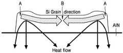
Translated fromKorean도 1은 본 발명에 따른 유기 전자발광디스플레이의 제조방법에서, 실리콘 아일랜드의 결정화시 열분포 및 이에 따른 결정화 과정를 설명하는 도면이다.1 is a view illustrating a heat distribution and a crystallization process according to the crystallization of silicon island in the method of manufacturing an organic electroluminescent display according to the present invention.
도 2는 본 발명에 따라 형성된 아일랜드로부터의 열흐름 경로와 이에 따른 결정핵 생성 및 성장을 설명하는 도면이다.2 is a diagram illustrating a heat flow path from an island formed in accordance with the present invention and thus nucleation and growth.
도 3은 본 발명에 의해 얻어진 다결정 실리콘의 SEM 이미지이다.3 is an SEM image of polycrystalline silicon obtained by the present invention.
도 4는 종래 방법에 의해 얻어진 다결정 실리콘의 SEM 이미지이다.4 is an SEM image of polycrystalline silicon obtained by a conventional method.
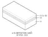
도 5a 내지 도 5f는 본 발명의 한 실시예에 따라 트랜지스터의 활성층으로 사용되는 다결정 실리콘 필름을 제조하는 과정을 보인 공정도이다.5A through 5F are process diagrams illustrating a process of manufacturing a polycrystalline silicon film used as an active layer of a transistor according to an embodiment of the present invention.
도 6a는 본 발명에 따른 유기 전자발광 디스플레이의 개략적 등가회로도이다.6A is a schematic equivalent circuit diagram of an organic electroluminescent display according to the present invention.
도 6b는 도 6a에 도시된 유기 전자발광 디스플레이의 드라이빙 트랜지스터(T1)와 스위칭 트랜지스터(T2)의 활성층의 결정성장 방향을 설명하는 도면이다.FIG. 6B is a diagram illustrating a crystal growth direction of an active layer of the driving transistor T1 and the switching transistor T2 of the organic electroluminescent display shown in FIG. 6A.
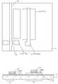
도 7a는 본 발명의 구체적인 실시예에 따른 유기 전자발광 디스플레이의 단위화소의 개략적 레이아웃을 보인다.7A shows a schematic layout of a unit pixel of an organic electroluminescent display according to a specific embodiment of the present invention.
도 7b는 도 7a 의 A - A' 선 단면도이다.FIG. 7B is a cross-sectional view taken along the line AA ′ of FIG. 7A.
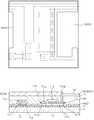
도 8a 내지 도 8k는 본 발명의 실시예에 따른 유기 전자발광 디스플레이의 제조방법의 공정도이다.8A to 8K are flowcharts illustrating a method of manufacturing an organic electroluminescent display according to an embodiment of the present invention.
본 발명은 유기 전자발광디스플레이 및 그 제조방법에 관한 것으로 상세히는서로 다른 이동도 및 낮은 오프-커런트 누설(off-current leakage)를 가지는 복수의 트랜지스터를 가지는 유기 전자발광디스플레이 및 그 제조방법에 관한 것이다.The present invention relates to an organic electroluminescent display and a method of manufacturing the same, and more particularly, to an organic electroluminescent display having a plurality of transistors having different mobility and low off-current leakage, and a method of manufacturing the same. .
AM(Active-Matrix) 유기 전자발광 디스플레이는 기본적으로 스위칭 트랜지스터와 드라이빙 트랜지스터를 구비한다. 일반적으로 알려진 바와 같이 스위칭 트랜지스터는 낮은 오프-커런트 누설(off-current leakage) 특성이 요구되고 드라이빙 트랜지스터는 높은 이동도(High mobility)의 특성이 요구된다.Active-Matrix (AM) organic electroluminescent displays basically include a switching transistor and a driving transistor. As is generally known, switching transistors require low off-current leakage characteristics and driving transistors require high mobility characteristics.
일반적으로 스위칭 트랜지스터와 드라이빙 트랜지스터는 동일 조건으로 제조된 하나의 실리콘필름으로 부터 얻어지기 때문에 위와 같이 서로 상반된 특성을 가지기 어렵다. 이러한 요구에 따라 높은 이동도의 실리콘을 이용해 스위칭 트랜지스터와 구동 트랜지스터를 제조하는 과정에서 스위칭 트랜지스터의 활성층에 LDD(low doped drain) 또는 오프셋(off-set) 구조를 형성함으로써 스위칭 트랜지스터의 이동도를 떨어뜨림과 아울러 오프-커런트 누설을 감소시킨다.In general, since the switching transistor and the driving transistor are obtained from one silicon film manufactured under the same conditions, it is difficult to have mutually opposite characteristics as described above. In accordance with these requirements, the mobility of the switching transistor is reduced by forming a low doped drain (LDD) or off-set structure in the active layer of the switching transistor during the manufacturing of the switching transistor and the driving transistor using high mobility silicon. It also reduces off-current leakage.
LDD 또는 오프셋 구조는 결과적으로 유기 전자발광 디스플레이의 제조과정 중 별도 공정으로서 진행되며 따라서 이러한 LDD 나 오프셋 구조가 없이 누설전류 의 억제가 가능하다면 경제적이 될 것이며, 이를 위한 새로운 설계의 연구가 필요하다.As a result, the LDD or offset structure is processed as a separate process in the manufacturing process of the organic electroluminescent display, and thus, if the leakage current can be suppressed without such an LDD or offset structure, it will be economical, and a new design study for this is needed.
본 발명은 낮은 누설전류의 스위칭 트랜지스터와 높은 이동도의 드라이빙 트랜지스터를 갖는 양질의 유기 전자발광 디스플레이 및 그 제조방법을 제공한다.The present invention provides a high quality organic electroluminescent display having a low leakage current switching transistor and a high mobility driving transistor, and a method of manufacturing the same.
본 발명에 따르면,According to the invention,
유기발광다이오드(OLED)와;An organic light emitting diode (OLED);
상기 OLED를 구동하는 드라이빙 트랜지스터와;A driving transistor for driving the OLED;
상기 드라이빙 트랜지스터의 동작을 제어하는 스위칭 트랜지스터를 구비하고,A switching transistor for controlling the operation of the driving transistor;
상기 드라이빙 트랜지스터의 활성층은 전류 채널에 나란한 종 방향으로 성장된 결정 구조를 가지며,The active layer of the driving transistor has a crystal structure grown in the longitudinal direction parallel to the current channel,
상기 스위칭 트랜지스터의 활성층은 전류 채널에 수직인 횡 방향으로 성장된 결정 구조를 갖는 것을 특징으로 하는 유기 전자발광디스플레이가 제공된다.The active layer of the switching transistor is provided with an organic electroluminescent display, characterized in that it has a crystal structure grown in the transverse direction perpendicular to the current channel.
또한 본 발명에 따르면, 발광다이오드(OLED)를 구동하는 드라이빙 트랜지스터와, 상기 드라이빙 트랜지스터를 구동하는 스위칭 트랜지스터를 구비하는 유기 전자발광 디스플레이의 제조하는 방법에 있어서,Further, according to the present invention, in the method of manufacturing an organic electroluminescent display comprising a driving transistor for driving a light emitting diode (OLED) and a switching transistor for driving the driving transistor,
기판에 전기절연성 열전도층을 형성하는 단계;Forming an electrically insulating thermally conductive layer on the substrate;
상기 열전도층 위에, 상기 스위칭 트랜지스터의 활성층을 제조하기 위한 것 으로 전류 채널의 종 방향으로 긴 길이를 가지는 제 1 실리콘 아일랜드를 형성하는 단계;Forming a first silicon island on the thermal conductive layer, the first silicon island having a long length in the longitudinal direction of the current channel for manufacturing the active layer of the switching transistor;
상기 드라이빙 트랜지스트의 활성층을 제조하기 위한 것으로 전류 채널의 횡방향으로 긴 제 2 실리콘 아일랜드를 형성하는 단계;Forming a second silicon island transverse to the current channel for fabricating an active layer of the driving transistor;
상기 제 1 실리콘 아일랜드를 결정화하여 상기 전류 채널의 횡방향으로 결정이 성장된 스위칭 트랜지스터의 활성층을 얻는 단계;Crystallizing the first silicon island to obtain an active layer of a switching transistor in which crystals are grown in the transverse direction of the current channel;
상기 제 2 실리콘 아일랜드를 결정화하여 상기 전류 채널의 종방향으로 전류 채널의 종 방향으로 결정이 성장된 상기 드라이빙 트랜지스터의 활성층을 얻는 단계; 그리고Crystallizing the second silicon island to obtain an active layer of the driving transistor in which crystals are grown in the longitudinal direction of the current channel in the longitudinal direction of the current channel; And
상기 활성층들을 이용하여 스위칭 트랜지스터와 드라이빙 트랜지스터를 제조하는 단계;를 포함하는 것을 특징으로 하는 유기 전자발광 디스플레이의 제조방법이 제공된다.A method of manufacturing an organic electroluminescent display is provided, comprising: manufacturing a switching transistor and a driving transistor using the active layers.
상기 본 발명의 실시예들에 따르면, 상기 열전도층은 상기 활성층들의 하부에 알루미늄 세라믹, 코발트 세라믹, Fe 세라믹 중의 어느 하나의 물질로 형성된다. 구체적인 실시예들에 따르면, 상기 열전도층의 상기 알루미늄 세라믹은 Al2O3, AlN 중의 어느 하나이며, 상기 코발트 세라믹은 CoO, Co3N4 중의 어느 하나, 그리고 상기 Fe 세라믹은 FeO, Fe2O3, Fe3O4, Fe2N 중의 어느 하나이다.According to the embodiments of the present invention, the thermal conductive layer is formed of any one material of aluminum ceramic, cobalt ceramic, Fe ceramic under the active layer. According to specific embodiments, the aluminum ceramic of the thermal conductive layer is any one of Al2 O3 , AlN, the cobalt ceramic is any one of CoO, Co3 N4 , and the Fe ceramic is FeO, Fe2 O3, is any ofFe 3 O 4, Fe 2 N .
상기와 같은 본 발명의 활성층을 형성하기 위한 실리콘의 결정화는 ELA에 의해 수행하며, 상기 결정화시 에너지 밀도는 400mJ/cm2이상이며, 상기 스위칭 트랜 지스터의 활성층의 횡방향 폭과 드라이빙 트랜지스터의 종방향 길이가 4 미크론 이상이 바람직하다.Crystallization of silicon for forming the active layer of the present invention as described above is performed by ELA, the energy density during the crystallization is 400mJ / cm2 As described above, the transverse width of the active layer of the switching transistor and the longitudinal length of the driving transistor are preferably 4 microns or more.
이하 첨부된 도면을 참조하면서 유기 전자발광디스플레이 및 그 제조방법의 실시예를 각각 설명한다.Hereinafter, embodiments of an organic electroluminescent display and a method of manufacturing the same will be described with reference to the accompanying drawings.
도 1은 본 발명에 따른 유기 전자발광디스플레이 및 그 제조방법에서 이용하는 실리콘 아일랜드의 결정화시 열분포 및 이에 따른 결정화 과정을 설명하는 도면이며, 도 2는 아일랜드로부터의 열 흐름 경로와 이에 따른 결정핵 생성 및 성장을 설명하는 도면이다.1 is a view illustrating a heat distribution during crystallization of a silicon island and a crystallization process according to the crystallization of the silicon island used in the organic electroluminescent display and a manufacturing method according to the present invention, FIG. It is a figure explaining growth.
실리콘 아일랜드(Si island)가 고열전도성을 갖는 물질 예를 들어 AlN 열전도층(Thermal Conducting layer) 위에 형성되어 있다. 열전도층은 석영, 유리 또는 플라스틱 등의 기판 위에 형성된다.Si islands are formed on a material having high thermal conductivity, for example, an AlN thermal conducting layer. The thermal conductive layer is formed on a substrate such as quartz, glass or plastic.
308nm 의 파장을 가지는 XeCl 엑시머 레이저가 실리콘 아일랜드에 조사되어 실리콘 아일랜드가 충분히 가열되며, 바람직하게는 완전히 용융된다. 고온 상태의 실리콘 아일랜드로부터의 열전도는 즉시 일어나며 이때에 그 하부의 열전도층에 의한 3 차원적 열흐름이 발생한다. 열전도층에서의 열전달 방향은 그 하부의 기판측 보다 열전도층의 횡방향으로 더 빠르고 크게 일어난다. 도면에서 화살표는 이를 설명하는 열흐름의 경로를 보인다. 도면에서 어두울수록 높은 온도 부분, 밝을 수 록 낮은 온도를 나타낸다. 실리콘 아일랜드의 중심부분은 다른 부분에 비해 온도가 높고 그 양측으로 갈수록 온도가 낮아진다. 따라서 이러한 횡방향 열적 구배(勾配)(lateral thermal gradient) 도 2에 도시된 바와 같은 열전도 경로 및 이에 따른 결정의 성장이 이루어진다. 즉, 열전도층에 의한 빠른 열전달에 의하면 실리콘 아일랜드의 양측 모서리로부터 열이 빠르게 빠져나간다. 이는 실리콘 아일랜드에서의 양단(A)에 먼저 결정핵(Crystalline Nucleus)이 먼저 생성되며, 따라서 점차적으로 실리콘 아일랜드의 가운데 부분으로 성장을 하게 되며, 최종적으로 실리콘 아일랜드의 중앙에서 결정경계(Grain Boundary, B)가 생기게 된다. 본 발명에 따르면 실리콘 아일랜드가 선 패터닝(pre-patterned)이 된 상태이기 때문에 어닐링 시 이의 양 모서리로부터 냉각이 빠르게 시작되고 따라서 여기에서 결정핵이 생성된다. 즉, 본 발명에 따르면 결정핵 생성 위치가 결정되기 때문에 완전 용융(full melting) 조건으로 실리콘 아일랜드를 열처리할 수 있게 된다. 이러한 완전 용융의 가능성은 매우 넓은 프로세스 윈도우 즉 매우 넓은 온도 범위에서의 열처리를 허용한다. 한편 선패터닝된 실리콘 아일랜드는 설계에 의해 그 위치 및 크기가 제어될 수 있기 때문에 기판의 소망하는 위치에 양질의 다결정 실리콘을 형성할 수 있다.An XeCl excimer laser having a wavelength of 308 nm is irradiated onto the silicon island so that the silicon island is sufficiently heated, and preferably completely melted. Heat conduction from the silicon island in the hot state occurs immediately, at which time three-dimensional heat flow by the underlying heat conduction layer occurs. The heat transfer direction in the heat conductive layer occurs faster and larger in the transverse direction of the heat conductive layer than in the substrate side below it. Arrows in the figure show the path of heat flow that describes it. The darker in the figure, the higher the temperature portion, the brighter the lower temperature. The central portion of the silicon island is hotter than the other parts and cooler toward both sides. Thus, such a lateral thermal gradient is shown, as shown in FIG. That is, according to the fast heat transfer by the heat conduction layer, heat is rapidly released from both edges of the silicon island. This results in the first formation of Crystalline Nucleus at both ends (A) in Silicon Island, thus gradually growing to the middle of Silicon Island, and finally at the center of Silicon Island. ). According to the present invention, since the silicon island is pre-patterned, cooling starts rapidly from both corners of the annealing and thus nuclei are generated. That is, according to the present invention, since the crystal nucleation position is determined, the silicon island can be heat treated under full melting conditions. The possibility of this complete melting allows for heat treatment over a very wide process window, ie a very wide temperature range. Pre-patterned silicon islands, on the other hand, can be formed of high quality polycrystalline silicon at a desired location of the substrate because its position and size can be controlled by design.
이러한 본 발명에 따르면 도 3에 도시된 바와 같은 다결정 실리콘을 얻을 수 있다. 도 3은 본 발명에 의해 얻어진 다결정 실리콘의 SEM 이미지이다. 도 3에서 결정폭은 2.5㎛ 이며 다결정 실리콘의 중간 부분에 결정 경계가 보인다. 여기에서 결정성장 방향은 다결정 실리콘의 좁은 폭방향(도면에서 좌우방향)으로 배향되어 있고, 따라서 폭방향으로 높은 이동도를 가지며, 그리고 폭 방향에 수직인 높이 방향(도면에서 상하방향)의 이동도는 폭방향에 비해 낮게 나타난다. 본 발명에서는 실리콘 아일랜드를 형성함에 있어서 일방향으로 긴게 연장된 직사각형으로 형성하여 길이 방향에 비해 폭방향으로 결정이 성장될 수 있도록 하며, 이러한 결정성장 방향의 선택이 가능한 방법을 유기 전자 발광 디스플레이의 트랜지스터의 제조에 이용한다.According to the present invention, it is possible to obtain polycrystalline silicon as shown in FIG. 3 is an SEM image of polycrystalline silicon obtained by the present invention. In FIG. 3, the crystal width is 2.5 μm and a crystal boundary is visible in the middle portion of the polycrystalline silicon. Here, the crystal growth direction is oriented in the narrow width direction (left and right direction in the drawing) of the polycrystalline silicon, and thus has a high mobility in the width direction, and the mobility in the height direction (up and down direction in the drawing) perpendicular to the width direction. Is lower than the width direction. In the present invention, the silicon islands are formed in a rectangular shape extending in one direction so that crystals can be grown in the width direction compared to the length direction. It is used for manufacture.
도 4는 종래의 일반적인 ELA에 의해 얻어진 다결정 실리콘의 SEM 이미지이다. 도 4에 도시된 종래 방법에 의해 얻어진 다결정 실리콘의 입경은 불과 0.3㎛로서 도 3에 도시된 본 발명에 의해 얻어진 다결정 실리콘에 비해 입경이 상대적으로 매우 작은 차이를 보인다.4 is an SEM image of polycrystalline silicon obtained by a conventional general ELA. The particle diameter of the polycrystalline silicon obtained by the conventional method shown in FIG. 4 is only 0.3 μm, which shows a relatively small difference in particle diameter compared to the polycrystalline silicon obtained by the present invention shown in FIG. 3.
위에서 설명된 열전도층은 하부의 기판 및 실리콘에 비해 높은 열전도성을 가지며 그 재료로는 AlN 이 선택될 수 있다. AlN 은 260W/mK 이상의 높은 열전도도를 가지면서도 6.3eV 정도의 밴드갭을 가짐으로써 양호한 전기적 절연성을 가진다. 또한 물리적 강도면에서도 높은 경도를 가질 뿐 아니라 광학적으로는 높은 투명성과 함께 화학적으로 좋은 안정성을 갖는다. 따라서 AlN 은 본 발명의 다결정 실리콘 필름의 제조에 바람직한 물질로 사용된다. 그 외의 고열전도성 물질로는 그리고 상기 열전도층은 Al2O3, AlN 등의 알루미늄 세라믹, CoO, Co3N4 등의 코발트 세라믹, FeO, Fe2O3, Fe3O4, Fe2N 등의 Fe 세라믹이 사용될 수 있다.The thermally conductive layer described above has higher thermal conductivity than the underlying substrate and silicon and AlN may be selected as the material. AlN has a high thermal conductivity of 260W / mK and a band gap of about 6.3eV, thereby providing good electrical insulation. In addition, it has not only high hardness in terms of physical strength but also chemically good stability with high transparency optically. Therefore, AlN is used as a preferable material for producing the polycrystalline silicon film of the present invention. As other high thermal conductivity materials, and the heat conductive layer may be Al2 O3 , aluminum ceramics such as AlN, cobalt ceramics such as CoO, Co3 N4 , FeO, Fe2 O3 , Fe3 O4 , Fe2 N, etc. Fe ceramics can be used.
위와 같이 결정 구조의 방향성을 가지는 실리콘 아일랜드는 결정방향의 순방향으로 높은 이동도를 가지며 그에 수직인 방향으로 상대적으로 낮은 이동도를 가진다. 상대적으로 낮은 이동도를 가지는 활성층에 의한 트랜지스터는 결과적으로 낮은 누설전류의 특성을 가진다.As described above, the silicon island having the orientation of the crystal structure has high mobility in the forward direction of the crystal direction and relatively low mobility in the direction perpendicular thereto. Transistors with active layers having relatively low mobility result in low leakage current characteristics.
이하에서는 상기와 같이 선택적인 결정방향을 가지는 스위칭 트랜지스터 및 드라이빙 트랜지스터의 활성층의 제조방법을 설명한다. 복잡성을 피하기 위하여 하나의 활성층의 제조방법에 대해 설명한다.Hereinafter, a method of manufacturing an active layer of a switching transistor and a driving transistor having a selective crystal direction as described above will be described. In order to avoid the complexity, a method of manufacturing one active layer will be described.
도 5a에 도시된 바와 같이, 석영, 유리 또는 플라스틱으로 된 기판(11)을 준비한다.As shown in Fig. 5A, a
도 5b에 도시된 바와 같이, 상기 기판(11) 위에 고열전도성 물질로 열전도층(11)을 약 2000 Å 정도의 두께로 형성한다. 이때에 물질 증착에는 반응성 스퍼터(reactive sputter)가 이용되며, 타겟 물질은 Al, 반응 가스는 10 sccm의 질소가 이용되며 반응실 내부 압력은 10mTorr 정도이며 플라즈마 파워는 약 300W 이다.As shown in FIG. 5B, the thermal
도 5c에 도시된 바와 같이 상기 열전도층(12) 위에 비정질 실리콘층(a-Si, 12)을 약 500 Å 정도의 두께로 형성한다. 이때의 증착은 CVD 또는 PVD 가 이용되며, 바람직하게는 PVD(Physical Vapor Deposition)를 이용한다. PVD 는 스퍼터링 타겟으로 Si을 이용한다. 이때의 가스는 50 sccm의 Ar, 기압은 5 mTorr 정도로 설정된다.As shown in FIG. 5C, an amorphous silicon layer (a-Si) 12 is formed on the thermal
도 5d에 도시된 바와 같이 상기 비정질 실리콘층(13)을 건식 식각법 등에 의해 패터닝하여 실리콘 아일랜드(13')를 얻는다. 이때의 실리콘 아일랜드(13')의 좁은 폭은 4 미크론으로 하며 길이는 4 미크론 이상으로 결정하며 이러한 비정질 실리콘 아일랜드는 반도체 소자 예를 들어 TFT의 활성층으로 이용된다.As shown in FIG. 5D, the
도 5e에 도시된 바와 같이 엑시머 레이저에 의해 상기 실리콘 아일랜드(13')를 어닐링한다. 이때에 레이저는 예를 들어 308nm의 XeCl 엑시머 레이저가 이용되 며 에너지는 400mJ/cm2 이상으로 설정한다. 이와 같은 열처리에 의해 도 5f에 도시된 바와 같이 기판 상(11)의 목적하는 위치에 큰 입경의 결정을 갖는 박막트랜지스터용 활성층(13")이 형성되며, 이 활성층(13")은 폭 방향으로의 결정성장 방향을 가지게 되어 도 3에 도시된 바와 같은 결정성장 방향을 가지게 된다.The silicon island 13 'is annealed by an excimer laser as shown in FIG. 5E. At this time, the laser is used, for example, XeCl excimer laser of 308nm and the energy is set to 400mJ / cm2 or more. By such heat treatment, as shown in FIG. 5F, an
위와 같은 과정을 통해 얻어진 활성층은 이용해 박막트랜지스터가 제조되며, 이때에 스위칭 트랜지스터와 드라이빙 트랜지스터를 갖는 유기 전자발광 디스플레이를 제조하기 위해서는 각 단위 화소 마다 두 개의 실리콘 아일랜드가 형성되어야 할 것이다.A thin film transistor is manufactured using the active layer obtained through the above process, and in order to manufacture an organic electroluminescent display having a switching transistor and a driving transistor, two silicon islands should be formed for each unit pixel.
도 6a는 2T-1C 구조를 가지는 본 발명에 따른 유기 전자발광디스플레이의 등가회로를 보이는 것으로 하나의 서브 픽셀 또는 단위 픽셀을 보이는 도면이다. 도 6을 살펴보면, 드라이빙 트랜지스터(T1)의 소스에 구동전압(VDD)가 인가되고 드레인에는 발광다이오드(OLED)의 애노드가 연결된다. 그리고 드라이빙 트랜지스터(T1)의 소스와 게이트에 스토리지 커패시터(Cs)가 병렬 접속되고, 발광다이오드(OLED)의 캐소드는 접지된다. 한편, 드라이빙 트랜지스터(T1)의 게이트에 스위칭 트랜지스터(T2)의 드레인이 접속되고 소스는 데이터 라인(DATA LINE)에 접속된다. 그리고 스위칭 트랜지스터(T2)의 게이트는 주사 라인(SCAN LINE)에 접속된다. 도 6B는 실리콘 결정 방향에 대한 드라이빙 트랜지스터(T1) 및 스위칭 트랜지스터(T2)의 전류 채널(화살표)의 관계를 보이는 도면이다. 도 6b에 도시된 바와 같이 본 발명에 따른 유기 전자발광 디스플레이에서, 상기 드라이빙 트랜지스터(T1)의 전류 채널이 활성층의 결정성장방향에 나란하게 배치되며 그리고 스위칭 트랜지스터(T2)의 전류 채널에 직교하는 방향으로 활성층의 결정 방향이 배치된다.FIG. 6A shows an equivalent circuit of an organic electroluminescent display according to the present invention having a 2T-1C structure, showing one sub-pixel or unit pixel. FIG. Referring to FIG. 6, a driving voltage VDD is applied to a source of the driving transistor T1, and an anode of the light emitting diode OLED is connected to a drain thereof. The storage capacitor Cs is connected in parallel to the source and the gate of the driving transistor T1, and the cathode of the light emitting diode OLED is grounded. On the other hand, the drain of the switching transistor T2 is connected to the gate of the driving transistor T1 and the source is connected to the data line DATA LINE. The gate of the switching transistor T2 is connected to the scan line SCAN LINE. FIG. 6B is a diagram showing the relationship between the current channel (arrow) of the driving transistor T1 and the switching transistor T2 with respect to the silicon crystal direction. In the organic electroluminescent display according to the present invention as shown in FIG. 6B, the current channel of the driving transistor T1 is disposed in parallel to the crystal growth direction of the active layer and is orthogonal to the current channel of the switching transistor T2. The crystal direction of the active layer is arranged.
이하에서는 본 발명에 구체적 실시예에 따른 유기 전자발광디스플레이 및 이의 제조방법을 설명한다.Hereinafter, an organic electroluminescent display and a method of manufacturing the same according to a specific embodiment of the present invention will be described.
도 7a는 본 발명에 따른 유기 전자발광 디스플레이의 개략적 레이아웃으로서 단위 화소(또는 서브 픽셀)의 구조를 보인다.7A shows the structure of a unit pixel (or subpixel) as a schematic layout of an organic electroluminescent display according to the present invention.
도 7a를 참조하면, 데이터 라인(Ys)과 파워 라인(Zd)이 나란하게 배치되고 이에 직교하는 방향으로 주사라인(Xs)이 배치된다. 주사라인(Xs)과 데이터 라인(Ys) 교차부분에 스위칭 트랜지스터(T2)가 위치하고, 주사라인(Xs)과 파워 라인(Zd)의 교차부 가까이에는 드라이빙 트랜지스터(T1)가 배치된다. 스위칭 트랜지스터(T2)와 드라이빙 트랜지스터(T1)의 사이에는 스토리지 커패시터(Cs)가 배치된다. 상기 스토리지 커패시터(Cs)의 일측 전극(Cs-b)은 파워 라인(Zd)으로 부터 연장되는 부분이며, 타측 전극(Cs-a)은 스위칭 트랜지스터(T2)의 드레인(T2d)과 드라이빙 트랜지스터(T1)의 게이트(T1g)에 배선층(S1)에 의해 연결된다. 스위칭 트랜지스터(T2)의 게이트(T2g)는 주사 라인(Xs)으로 부터 연장되는 부분이다. 여기에서 본 발명의 특징에 따라 상기 드라이빙 트랜지스터(T1)의 활성층(T1c)은 전류 채널에 수직인 방향으로 길게 연장되며 실리콘 결정은 활성층(T1c)은 전류 채널(전류유동방향)에 나란한 종 방향으로 성장되며, 상기 스위칭 트랜지스터(T2)의 활성층(T2c)은 전류 채널에 나란한 방향으로 길게 연장되며 실리콘 결정은 전류채널에 수직인 횡 방향으로 성장되어 있다.Referring to FIG. 7A, the data line Ys and the power line Zd are arranged side by side and the scan line Xs is disposed in a direction orthogonal thereto. The switching transistor T2 is positioned at the intersection of the scan line Xs and the data line Ys, and the driving transistor T1 is disposed near the intersection of the scan line Xs and the power line Zd. The storage capacitor Cs is disposed between the switching transistor T2 and the driving transistor T1. One electrode Cs-b of the storage capacitor Cs extends from the power line Zd, and the other electrode Cs-a is a drain T2d of the switching transistor T2 and a driving transistor T1. Is connected to the gate T1g by the wiring layer S1. The gate T2g of the switching transistor T2 is a portion extending from the scan line Xs. According to an embodiment of the present invention, the active layer T1c of the driving transistor T1 extends in a direction perpendicular to the current channel, and the silicon crystal of the active layer T1c extends in the longitudinal direction parallel to the current channel (current flow direction). The active layer T2c of the switching transistor T2 extends in a direction parallel to the current channel, and the silicon crystal is grown in a transverse direction perpendicular to the current channel.
도 7b는 도 7A의 A - A' 선 단면, 즉 스토리지 커패시터(Cs)와 드라이빙 트랜지스터(T1)의 횡단면을 보인다. 도 7b를 참조하면, 기판(11)에 SiO2또는SiON 등의 절연 물질로 된 버퍼층으로서 실리콘 아일랜드 열처리시 실리콘의 결정화를 돕는 절연성 고열전도층(12)이 형성되고, 이 위에 스토리지 커패시터(Cs)와 드라이빙 트랜지스터(T1)가 형성된다. 드라이빙 트랜지스터(T1)는 열전도층(12)위에 형성되는 소스(T1s), 및 드레인(T1d)을 포함하는 다결정 실리콘(p-Si) 층과 그 위의 SiO2 등에 의한 게이트 절연층(13) 및 게이트(T1g)를 구비한다. 드라이빙 트랜지스터(T1) 위에는 SiO2 ,SiNx 등에 의한 ILD층(Interlayer Dielectric Layer, 14)이 형성되어 있다. ILD 층(14)에는 상기 다결정 실리콘층(p-Si)의 소스 및 드레인으로 통하는 비아홀(14s, 14d)이형성되어 있고 이 위에 금속성 소스 전극(T1se) 및 드레인 전극(T1de)이 형성되어 있다.FIG. 7B is a cross-sectional view taken along the line AA ′ of FIG. 7A, that is, the cross section of the storage capacitor Cs and the driving transistor T1. Referring to FIG. 7B, SiO2 may be formed on the
한편, 스토리지 커패시터(Cs)는 상기 게이트(T1g)와 동일물질로 동시에 형성되는 하부 전극(Cs-a) 및 상부 전극(Cs-b) 및 이 사이의 ILD층(14)을 포함한다. 상기 스토리지 커패시터(Cs)와 드라이빙 트랜지스터(T1)의 위에는 절연층(16)이 형성되고 여기에 상기 드라이빙 트랜지스터(T1)의 드레인 전극(T1de) 등 전기적 요소에 대응하는 비아홀(15')이 형성되어 있다. 비아홀(15') 위쪽에는 ITO 등의 투명성 도전물질로 된 애노드(Anode)가 형성되어 있고 이의 일측에는 절연물질로 된 뱅크(BANK)가 형성되어 있다. 상기 애노드(Anode)와 뱅크(Bank) 위에는 공지의 정공수송층, 발광층, 전자수송층 등을 포함하는 OLED 가 형성되고 그 위에 금속성 캐소드 (cathode)가 형성되어 있고 캐소드(cathode) 위에는 캐소드(cathode)를 보호하는 패시베이션층(17)이 형성되어 있다. 위의 설명에서는 스위칭 트랜지스터에 대해서설명되지 않았으나 스위칭 트랜지스터는 드라이빙 트랜지스터와 동시에 제작되고 실리콘, 게이트 절연층, 게이트, ILD 층, 소스 전극 및 드레인 전극들 각각이 동일 물질에 의해 동시에 형성된다.On the other hand, the storage capacitor Cs includes a lower electrode Cs-a and an upper electrode Cs-b, which are simultaneously formed of the same material as the gate T1g, and an
전술한 구조의 전계발광 디스플레이의 레이아웃은 실현 가능한 본 발명의 구체적인 한 예로서 이러한 레이아웃 및 이의 수정은 본 발명의 기술적 범위를 제한하지 않는다.The layout of the electroluminescent display of the above-described structure is a specific example of the present invention that can be realized, and this layout and its modifications do not limit the technical scope of the present invention.
도 8a 내지 도 8k는 상기와 같은 본 발명에 따른 유기 전자발광 디스플레이의 제조방법을 보이는 공정도로서, 각 도면의 위쪽은 단위 화소 전체의 레이아웃을 보이며, 아래의 도면은 스토리지 커패시터와 드라이빙 트랜지스터가 형성되는 부분의 단면도이며, 도 8c의 아래의 단면도는 윗 도면의 B-B 선 단면도이다.8A to 8K are process charts illustrating a method of manufacturing an organic electroluminescent display according to the present invention as described above. The upper part of each drawing shows a layout of an entire unit pixel, and the lower drawing shows a storage capacitor and a driving transistor. Sectional drawing of the part, and sectional drawing of FIG. 8C below is BB sectional drawing of an upper figure.
도 8a에 도시된 바와 같이 유리 또는 플라스틱 기판(11)에 버퍼층으로서 전기적 절연성을 가지면서도 높은 열전도성을 가지는 열전도층(12)을 증착한다. 고열전도성 물질은 기판 및 실리콘에 비해 높은 열전도도를 가지는 물질로서 Al2O3, AlN 등의 알루미늄 세라믹, CoN, CaO 등의 코발트 세라믹, FeO, Fe2O3, Fe3O4, Fe2N 등의 Fe 세라믹 등으로 이루어진 그룹에 선택된 어느 하나의 물질, 바람직하게 AlN로 형성한다. 고열전도성 물질층의 두께는 약 2000Å 정도이며, 증착에는 반응성 스퍼터(reactive sputter)가 이용된다. 타겟물질로 Al, 반응 가스는 10 sccm의 질소가 이 용되며, 반응실 내부 압력은 10mTorr 정도이며 프라즈마 파워는 약 300W 이다.As shown in FIG. 8A, a thermally
도 8b에 도시된 바와 같이, 상기 열전도층(12) 위에 비정질 실리콘층(13)을 형성한다. 비정질 실리콘(a-Si)의 증착은 CVD 또는 스퍼터링법등에 의해 진행된다. 이때에 비정질 실리콘층의 두께는 500 Å 정도이며, 바람직하게는 PVD에 의해 형성된다. PVD 는 스퍼터링 타겟으로 Si을 이용한다. 이때의 가스는 50 sccm의 Ar, 기압은 5 mTorr 정도로 설정된다.As shown in FIG. 8B, an
도 8c에 도시된 바와 같이, 습식 또는 건식 식각법에 의해 상기 비정질 실리콘층을 패터닝하여 드라이빙 트랜지스터(T1)와 스위칭 트랜지스터(T2)의 활성층을 제조하기 위한 제 1 실리콘 아일랜드 및 제 2 실리콘 아일랜드를 형성한다. 이때에 본 발명에 특징에 따라, 상기 스위칭 트랜지스터의 활성층(T2c)을 제조하기 위한 제 1 실리콘 아일랜드는 전류의 채널에 나란한 방향으로 길게 형성되며, 반대로 드라이빙 트랜지스터(T1)의 활성층(T1c)을 제조하기 위한 제 2 실리콘 아일랜드는 전류 채널의 횡방향으로 길게 형성된다.As shown in FIG. 8C, the amorphous silicon layer is patterned by wet or dry etching to form a first silicon island and a second silicon island for manufacturing an active layer of the driving transistor T1 and the switching transistor T2. do. At this time, according to the present invention, the first silicon island for manufacturing the active layer (T2c) of the switching transistor is formed long in the direction parallel to the channel of the current, on the contrary to manufacture the active layer (T1c) of the driving transistor (T1) The second silicon island is formed long in the transverse direction of the current channel.
도 8d에 도시된 바와 같이, 상기 실리콘 아일랜드들을 ELA에 의해 어닐링하여 비정질실리콘을 다결정 실리콘으로 변환한다. 이때에 레이저는 예를 들어 308nm의 XeCl 엑시머 레이저가 이용되며 에너지는 400mJ/cm2 이상으로 설정한다. 이러한 열처리에 의하면 도 1 및 도 2와 함께 설명된 과정을 통해 결정화된다. 이러한 결정화를 통해서 스위칭 트랜지터(T2)의 활성층(T2c)은 전류 채널의 횡 방향으로 결정화되어 따라서 다결정 실리콘의 결정성장 방향으로 나타나는 이동도에 비해 낮은 이동도를 가지게 된다. 그리고 드라이빙 트랜지스터(T1)는 다결정 실리콘의 결정성장 방향으로 전류 채널이 배치되므로 높은 이동도를 가지게 된다.As shown in FIG. 8D, the silicon islands are annealed by ELA to convert amorphous silicon into polycrystalline silicon. At this time, the laser is used, for example, XeCl excimer laser of 308nm and the energy is set to 400mJ / cm2 or more. This heat treatment crystallizes through the process described with reference to FIGS. 1 and 2. Through this crystallization, the active layer T2c of the switching transistor T2 is crystallized in the transverse direction of the current channel, and thus has a lower mobility than that shown in the crystal growth direction of the polycrystalline silicon. The driving transistor T1 has a high mobility because the current channel is disposed in the crystal growth direction of the polycrystalline silicon.
도 8e에 도시된 바와 같이, 상기 기판(11) 상의 적층 구조물 위에 게이트 절연층(SiO2) 및 게이트 물질로 AlNd 합금을 순차적으로 증착한 후 마스크(PR)를 이용해 패터닝한다. 이 과정에서 스위칭 트랜지스터 및 드라이빙 트랜지스터의 게이트(T2g, T1g) 및 스토리지 커패시터의 하부 전극(Cs-a) 가 얻어진다. 여기에서 스위칭 트랜지스터(T2)의 게이트(T2g)는 스캔 라인(Xs)과 함께 형성되며 스캔 라인(Xs)의 일부이다. 이와 같이 게이트(T1g, T2g)가 패터닝된 후 게이트(T1g, T2g)에 덮이지 않은 실리콘 아일랜드의 노출부분에 대해 불순물을 주입하고 열처리에 의해 도핑영역을 활성화한다.As shown in FIG. 8E, an AlNd alloy is sequentially deposited on the stack structure on the
도 8f에 도시된 바와 같이 상기 기판(11)의 적층 구조물 위에 전면적으로 SiO2, SiNx 등을 증착하여 ILD층(14)을 얻는다. 상기 제1절연층(14a, 14b)은 소정의 에칭조건에 대해 선택성을 가진 서로 다른 물질로 형성된다. 여기에서, 상기 ILD층(14)은 둘 이상의 다른 절연층으로 형성될 수 있다.As shown in FIG. 8F, the
도 8g에 도시된 바와 같이, 상기 ILD(14)에서 상기 아일랜드의 소스, 드레인 그리고 위치를 달리하는 트랜지스터들과 커패시터의 전기적 연결을 위한 콘택홀(14')을 형성한다. 이때에 건식 식각법을 이용함이 바람직하다.As shown in FIG. 8G, a
도 8h에 도시된 바와 같이, 스토리지 커패시터(Cs)의 상부 전극(Cs-b)과 트랜지스터의 소스 전극(T2se, T1se) 및 드레인 전극(T2de, T1de)을 형성한다. 이 공 정은 일반적으로 알려진 AlNd 등의 금속층의 형성 및 금속층의 패터닝에 의해 이루어 진다.As shown in FIG. 8H, the upper electrodes Cs-b of the storage capacitor Cs, the source electrodes T2se and T1se and the drain electrodes T2de and T1de of the transistor are formed. This process is generally accomplished by the formation of known metal layers such as AlNd and patterning of the metal layers.
도 8i에 도시된 바와 같이, 상기 기판(11)의 적층 구조물 위에 절연층(16)을 형성한 후 상기 드라이빙 트랜지스터(T1)의 드레인 전극(T1de)으로 통하는 비아홀(16')을 형성한다.As shown in FIG. 8I, after the insulating
도 8j에 도시된 바와 같이, 상기 절연층(16)의 비아홀(16') 위에 ITO 등의 투명 도전성 물질로 애노드(anode)를 형성한다. 역시 여기에는 애노드 물질의 증착 및 이의 패터닝 과정이 수반된다.As shown in FIG. 8J, an anode is formed of a transparent conductive material such as ITO on the via
도 8k에 도시된 바와 같이, 상기 애노드(anode)가 형성되지 않은 절연층(16)의 일측에 절연물질 예를 들어 PA로 뱅크를 형성한 후 일반적인 공정을 통해 도 7a 및 7b에 도시된 형태의 본 발명의 실시예에 따른 유기발광디스플레이를 완성한다.As shown in FIG. 8K, a bank is formed of an insulating material, for example, PA, on one side of the insulating
위에서 설명된 본 발명의 유기 전자발광 디스플레이는 탑게이트 박막트랜지스터를 적용하는 것이나 본 발명의 다른 실시예에 따르면 활성층의 하부에 게이트가 위치하는 바텀 게이트 박막트랜지스터를 적용하며, 이의 구조 및 제조방법은 용이하게 구현될 수 있으며 청구항에 기재된 발명들의 기술적 범위를 제한하지 않는다.The organic electroluminescent display of the present invention described above uses a top gate thin film transistor, but according to another embodiment of the present invention, a bottom gate thin film transistor having a gate positioned under the active layer is applicable, and its structure and manufacturing method are easy. It does not limit the technical scope of the inventions set forth in the claims.
상기와 같은 본 발명에 따르면, 유기 전자발광 디스플레이를 설계함에 있어서 스위칭 트랜지스터와 드라이빙 트랜지스터의 요구 조건에 부응할 수 있다. 즉, 본 발명에 의해 결정성장 방향을 콘트롤하고 이를 박막트랜지스터의 활성층에 요구 되는 방향으로 배치 설계함으로써 저이동도 활성층 및 이에 따른 저누설전류의 스위칭 트랜지스터 그리고 고이동도 활성층 및 이에 따른 매우 응답성 및 뛰어나 드라이빙 트랜지스터를 제조할 수 있다.According to the present invention as described above, in the design of the organic electroluminescent display can meet the requirements of the switching transistor and the driving transistor. That is, according to the present invention, by controlling the direction of crystal growth and arranging it in the direction required for the active layer of the thin film transistor, the low mobility active layer, the low leakage current switching transistor and the high mobility active layer, and therefore the highly responsive and Excellent driving transistor can be manufactured.
이러한 본 발명의 제조방법은 유기 전자발광 디스플레이로서 다결정 실리콘 박막트랜지스터 유기 전자발광 디스플레이 및 그 제조방법에 적합하다.Such a manufacturing method of the present invention is suitable for a polycrystalline silicon thin film transistor organic electroluminescent display and its manufacturing method as an organic electroluminescent display.
이러한 본원 발명의 이해를 돕기 위하여 몇몇의 모범적인 실시예가 설명되고 첨부된 도면에 도시되었으나, 이러한 실시예들은 단지 넓은 발명을 예시하고 이를 제한하지 않는다는 점이 이해되어야 할 것이며, 그리고 본 발명은 도시되고 설명된 구조와 배열에 국한되지 않는다는 점이 이해되어야 할 것이며, 이는 다양한 다른 수정이 당 분야에서 통상의 지식을 가진 자에게 일어날 수 있기 때문이다.While some exemplary embodiments have been described and illustrated in the accompanying drawings in order to facilitate understanding of the present invention, it should be understood that these embodiments merely illustrate the broad invention and do not limit it, and the invention is illustrated and described. It is to be understood that the invention is not limited to structured arrangements and arrangements, as various other modifications may occur to those skilled in the art.
Claims (16)
Translated fromKoreanPriority Applications (3)
| Application Number | Priority Date | Filing Date | Title |
|---|---|---|---|
| KR1020060014695AKR20070082191A (en) | 2006-02-15 | 2006-02-15 | Organic electroluminescent display and manufacturing method |
| JP2007023321AJP2007221120A (en) | 2006-02-15 | 2007-02-01 | ORGANIC LIGHT EMITTING DEVICE AND MANUFACTURING METHOD THEREOF |
| US11/675,132US20070187676A1 (en) | 2006-02-15 | 2007-02-15 | Organic electro-luminescent display and method of fabricating the same |
Applications Claiming Priority (1)
| Application Number | Priority Date | Filing Date | Title |
|---|---|---|---|
| KR1020060014695AKR20070082191A (en) | 2006-02-15 | 2006-02-15 | Organic electroluminescent display and manufacturing method |
Publications (1)
| Publication Number | Publication Date |
|---|---|
| KR20070082191Atrue KR20070082191A (en) | 2007-08-21 |
Family
ID=38367457
Family Applications (1)
| Application Number | Title | Priority Date | Filing Date |
|---|---|---|---|
| KR1020060014695AWithdrawnKR20070082191A (en) | 2006-02-15 | 2006-02-15 | Organic electroluminescent display and manufacturing method |
Country Status (3)
| Country | Link |
|---|---|
| US (1) | US20070187676A1 (en) |
| JP (1) | JP2007221120A (en) |
| KR (1) | KR20070082191A (en) |
Families Citing this family (9)
| Publication number | Priority date | Publication date | Assignee | Title |
|---|---|---|---|---|
| US8441018B2 (en)* | 2007-08-16 | 2013-05-14 | The Trustees Of Columbia University In The City Of New York | Direct bandgap substrates and methods of making and using |
| KR20100036624A (en)* | 2008-09-30 | 2010-04-08 | 삼성전자주식회사 | Thin film transistor substrate and organic light emitting display having the same |
| KR101100999B1 (en)* | 2009-01-13 | 2011-12-29 | 삼성모바일디스플레이주식회사 | CMOS thin film transistor, manufacturing method thereof and organic light emitting display device having same |
| KR101048965B1 (en)* | 2009-01-22 | 2011-07-12 | 삼성모바일디스플레이주식회사 | Organic electroluminescent display |
| KR101666661B1 (en)* | 2010-08-26 | 2016-10-17 | 삼성디스플레이 주식회사 | Thin film transistor substrate and flat panel display apparatus |
| KR101305845B1 (en)* | 2011-11-16 | 2013-09-06 | 엘지이노텍 주식회사 | Solar cell apparatus and method of fabricating the same |
| KR20170024203A (en)* | 2015-08-24 | 2017-03-07 | 삼성디스플레이 주식회사 | Thin film transistor, method for manufacturing the same, and organic light emitting display |
| CN107068724B (en)* | 2017-04-24 | 2020-06-12 | 京东方科技集团股份有限公司 | OLED display panel and preparation method thereof, OLED display |
| KR102621591B1 (en)* | 2018-09-11 | 2024-01-08 | 삼성디스플레이 주식회사 | Display apparatus |
Family Cites Families (17)
| Publication number | Priority date | Publication date | Assignee | Title |
|---|---|---|---|---|
| JPH06296023A (en)* | 1993-02-10 | 1994-10-21 | Semiconductor Energy Lab Co Ltd | Thin-film semiconductor device and manufacture thereof |
| JP2814049B2 (en)* | 1993-08-27 | 1998-10-22 | 株式会社半導体エネルギー研究所 | Semiconductor device and manufacturing method thereof |
| US5742075A (en)* | 1994-10-07 | 1998-04-21 | Iowa State University Research Foundation, Inc. | Amorphous silicon on insulator VLSI circuit structures |
| US6497763B2 (en)* | 2001-01-19 | 2002-12-24 | The United States Of America As Represented By The Secretary Of The Navy | Electronic device with composite substrate |
| JP2003017702A (en)* | 2001-06-29 | 2003-01-17 | Toshiba Corp | Flat panel display and manufacturing method thereof |
| US6781060B2 (en)* | 2002-07-26 | 2004-08-24 | X-Ray Optical Systems Incorporated | Electrical connector, a cable sleeve, and a method for fabricating an electrical connection |
| JP2003241688A (en)* | 2002-02-18 | 2003-08-29 | Matsushita Electric Ind Co Ltd | Display device |
| US6875998B2 (en)* | 2002-03-26 | 2005-04-05 | Semiconductor Energy Laboratory Co., Ltd. | Semiconductor device, method of manufacturing the same, and method of designing the same |
| JP2004063478A (en)* | 2002-04-11 | 2004-02-26 | Fumimasa Yo | Thin film transistor and method of manufacturing the same |
| JP2003332350A (en)* | 2002-05-17 | 2003-11-21 | Hitachi Ltd | Thin film semiconductor device |
| US20040087116A1 (en)* | 2002-10-30 | 2004-05-06 | Junichiro Nakayama | Semiconductor devices and methods of manufacture thereof |
| US20040084679A1 (en)* | 2002-10-30 | 2004-05-06 | Sharp Kabushiki Kaisha | Semiconductor devices and methods of manufacture thereof |
| US7417252B2 (en)* | 2003-07-18 | 2008-08-26 | Samsung Sdi Co., Ltd. | Flat panel display |
| KR101044489B1 (en)* | 2003-12-29 | 2011-06-27 | 엘지디스플레이 주식회사 | Polysilicon liquid crystal display device having a large width channel and its manufacturing method |
| KR100557235B1 (en)* | 2003-12-30 | 2006-03-07 | 엘지.필립스 엘시디 주식회사 | Organic EL device and method of manufacturing the same |
| KR100594865B1 (en)* | 2004-08-10 | 2006-06-30 | 엘지.필립스 엘시디 주식회사 | Organic EL device and method of manufacturing the same |
| JP2007030361A (en)* | 2005-07-27 | 2007-02-08 | Fujifilm Holdings Corp | Liquid discharge head and imaging device |
- 2006
- 2006-02-15KRKR1020060014695Apatent/KR20070082191A/ennot_activeWithdrawn
- 2007
- 2007-02-01JPJP2007023321Apatent/JP2007221120A/enactivePending
- 2007-02-15USUS11/675,132patent/US20070187676A1/ennot_activeAbandoned
Also Published As
| Publication number | Publication date |
|---|---|
| US20070187676A1 (en) | 2007-08-16 |
| JP2007221120A (en) | 2007-08-30 |
Similar Documents
| Publication | Publication Date | Title |
|---|---|---|
| KR100882909B1 (en) | Thin film transistor, manufacturing method thereof, organic light emitting display device comprising same, and manufacturing method thereof | |
| US7919777B2 (en) | Bottom gate thin film transistor and method of manufacturing the same | |
| KR20070082191A (en) | Organic electroluminescent display and manufacturing method | |
| US8604483B2 (en) | Thin film semiconductor device, display device using such thin film semiconductor device and manufacturing method thereof | |
| US7691545B2 (en) | Crystallization mask, crystallization method, and method of manufacturing thin film transistor including crystallized semiconductor | |
| US8878186B2 (en) | Semiconductor device and display apparatus | |
| US20060273862A1 (en) | Semiconductor thin film manufacturing method, electronic device, and liquid crystal display device | |
| JP4263609B2 (en) | Mask for polycrystalline silicon and method of manufacturing thin film transistor using the same | |
| US20060084204A1 (en) | Method of manufacturing a thin film transistor | |
| JP4640690B2 (en) | Manufacturing method of active matrix organic EL display device | |
| JP2004072092A (en) | Method for crystallizing silicon thin film, thin film transistor using the same, and flat panel display device having the thin film transistor | |
| KR100600853B1 (en) | Flat panel display and manufacturing method | |
| US20070155067A1 (en) | Method of fabricating polycrystalline silicon film and method of fabricating thin film transistor using the same | |
| JP2011243988A (en) | Low-temperature polysilicon thin film and method of manufacturing the same, transistor, and display apparatus | |
| US7803699B2 (en) | Polysilicon thin film transistor and method of fabricating the same | |
| CN104078621B (en) | Low-temperature polysilicon film transistor, its preparation method and array base palte and display device | |
| JP5937332B2 (en) | Thin film transistor substrate and manufacturing method thereof | |
| US8535994B2 (en) | Thin-film transistor array device manufacturing method | |
| US8603869B2 (en) | Method of fabricating thin film transistor having amorphous and polycrystalline silicon | |
| US20070287232A1 (en) | Bottom gate thin film transistor and method of manufacturing the same | |
| KR101009429B1 (en) | Polycrystalline silicon film, thin film transistor comprising same, and method for manufacturing same | |
| JP3845569B2 (en) | Thin film semiconductor device, method for manufacturing the same, and electronic device including the device | |
| KR101043788B1 (en) | Method for manufacturing polycrystalline silicon film and method for manufacturing thin film transistor including same | |
| KR100700008B1 (en) | Thin film transistor and its manufacturing method | |
| JP2004006974A (en) | Method of manufacturing active matrix circuit |
Legal Events
| Date | Code | Title | Description |
|---|---|---|---|
| PA0109 | Patent application | Patent event code:PA01091R01D Comment text:Patent Application Patent event date:20060215 | |
| PG1501 | Laying open of application | ||
| PC1203 | Withdrawal of no request for examination | ||
| WITN | Application deemed withdrawn, e.g. because no request for examination was filed or no examination fee was paid |