KR20070075650A - Method and apparatus for mapping and transmitting coded symbols in frequency division multiple access system - Google Patents
Method and apparatus for mapping and transmitting coded symbols in frequency division multiple access systemDownload PDFInfo
- Publication number
- KR20070075650A KR20070075650AKR1020060004154AKR20060004154AKR20070075650AKR 20070075650 AKR20070075650 AKR 20070075650AKR 1020060004154 AKR1020060004154 AKR 1020060004154AKR 20060004154 AKR20060004154 AKR 20060004154AKR 20070075650 AKR20070075650 AKR 20070075650A
- Authority
- KR
- South Korea
- Prior art keywords
- channel estimation
- mapping
- data
- block
- pilot
- Prior art date
- Legal status (The legal status is an assumption and is not a legal conclusion. Google has not performed a legal analysis and makes no representation as to the accuracy of the status listed.)
- Granted
Links
Images


Classifications
- E—FIXED CONSTRUCTIONS
- E01—CONSTRUCTION OF ROADS, RAILWAYS, OR BRIDGES
- E01D—CONSTRUCTION OF BRIDGES, ELEVATED ROADWAYS OR VIADUCTS; ASSEMBLY OF BRIDGES
- E01D19/00—Structural or constructional details of bridges
- E01D19/04—Bearings; Hinges
- E01D19/041—Elastomeric bearings
- H—ELECTRICITY
- H04—ELECTRIC COMMUNICATION TECHNIQUE
- H04B—TRANSMISSION
- H04B7/00—Radio transmission systems, i.e. using radiation field
- H04B7/24—Radio transmission systems, i.e. using radiation field for communication between two or more posts
- H04B7/26—Radio transmission systems, i.e. using radiation field for communication between two or more posts at least one of which is mobile
- H04B7/2621—Radio transmission systems, i.e. using radiation field for communication between two or more posts at least one of which is mobile using frequency division multiple access [FDMA]
- H—ELECTRICITY
- H04—ELECTRIC COMMUNICATION TECHNIQUE
- H04L—TRANSMISSION OF DIGITAL INFORMATION, e.g. TELEGRAPHIC COMMUNICATION
- H04L5/00—Arrangements affording multiple use of the transmission path
- H04L5/003—Arrangements for allocating sub-channels of the transmission path
- H04L5/0044—Allocation of payload; Allocation of data channels, e.g. PDSCH or PUSCH
Landscapes
- Engineering & Computer Science (AREA)
- Signal Processing (AREA)
- Computer Networks & Wireless Communication (AREA)
- Mechanical Engineering (AREA)
- Architecture (AREA)
- Civil Engineering (AREA)
- Structural Engineering (AREA)
- Mobile Radio Communication Systems (AREA)
- Detection And Prevention Of Errors In Transmission (AREA)
Abstract
Translated fromKoreanDescription
Translated fromKorean도 1은 통상적인 OFDM 시스템의 송신기 구조를 도시한 도면.1 shows a transmitter structure of a conventional OFDM system.
도 2는 통상적인 SC-FDMA 시스템의 송신기 구조를 도시한 도면.2 shows a transmitter structure of a conventional SC-FDMA system.
도 3은 통상적인 SC-FDMA 시스템의 매핑기 동작을 보다 상세히 도시한 도면.3 illustrates in more detail the mapper operation of a typical SC-FDMA system.
도 4는 종래기술에 따른 파일럿의 주파수 분할 다중화 동작을 도시한 도면.4 illustrates a frequency division multiplexing operation of a pilot according to the prior art.
도 5는 종래기술에 따른 파일럿의 시간 분할 다중화 동작을 도시한 도면.5 illustrates a time division multiplexing operation of a pilot according to the prior art.
도 6은 LTE 시스템에서의 역방향 전송 프레임 및 서브프레임의 형식을 도시한 도면.6 illustrates the format of a reverse transmission frame and a subframe in an LTE system.
도 7은 본 발명의 바람직한 실시예에 따른 송신기의 동작을 도시한 흐름도.7 is a flowchart illustrating operation of a transmitter in accordance with a preferred embodiment of the present invention.
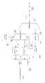
도 8은 본 발명의 바람직한 실시예에 따른 송신기 구조를 도시한 도면.8 illustrates a structure of a transmitter according to a preferred embodiment of the present invention.
도 9는 본 발명의 바람직한 실시예에 따른 수신기의 동작 도시한 흐름도.9 is a flowchart illustrating operation of a receiver according to a preferred embodiment of the present invention.
도 10은 본 발명의 바람직한 실시예에 따른 수신기의 구조를 도시한 도면.10 is a diagram showing the structure of a receiver according to a preferred embodiment of the present invention.
본 발명은 직교 주파수 분할 다중 접속(Orthogonal Frequency Division Multiple Access; 이하 OFDM이라 칭함) 무선 통신 시스템, 혹은 단반송파 주파수 분할 다중 접속(Single Carrier Frequency Division Multiple Access: 이하 SC-FDMA라 칭함) 무선 통신 시스템과 같은 통신 시스템에 관한 것으로서, 특히 채널 추정 성능에 따라 데이터의 부호화 심볼을 매핑하는 규칙을 제시하는 방법 및 장치에 관한 것이다.The present invention relates to an orthogonal frequency division multiple access (OFDM) wireless communication system, or a single carrier frequency division multiple access (hereinafter referred to as SC-FDMA) wireless communication system. The present invention relates to a communication system, and more particularly, to a method and an apparatus for providing a rule for mapping encoded symbols of data according to channel estimation performance.
최근 이동통신 시스템에서는 무선 채널에서 고속데이터 전송에 유용한 방식으로 직교 주파수 분할 다중 접속(OFDM)방식, 혹은 이와 비슷한 방식으로 단반송파 주파수 분할 다중 접속(SC-FDMA)방식이 활발하게 연구되고 있다.Recently, in the mobile communication system, orthogonal frequency division multiple access (OFDM), or a similar method, SC-FDMA has been actively studied as a method useful for high-speed data transmission in a wireless channel.
상기 OFDM 방식은 다수 개의 캐리어 (Multi-Carrier)를 사용하여 데이터를 전송하는 방식으로서, 직렬로 입력되는 심볼(Symbol) 열을 병렬 변환하고 이들 각각을 상호 직교성을 갖는 다수의 서브 캐리어(sub-carrier)들, 즉 다수의 서브 캐리어 채널(sub-carrier channel)들로 변조하여 전송하는 멀티캐리어 변조(Multi Carrier Modulation) 방식의 일종이다.The OFDM method is a method of transmitting data using a plurality of carriers (Multi-Carrier), a plurality of sub-carriers having a parallel conversion of the serial (symbol) input serially and each orthogonal to each other ), That is, a type of multi-carrier modulation that modulates and transmits a plurality of sub-carrier channels.
도 1은 통상적인 OFDM 시스템의 송신기 구조를 도시한 도면이다.1 is a diagram illustrating a transmitter structure of a conventional OFDM system.
상기 도 1을 참조하면, OFDM 송신기는 부호화기(101)와 변조기(102)와 직/병렬 변환기(103)와 역 고속 퓨리에 변환(Inverse Fast Fourier Transform: 이하 IFFT라 칭함) 블록(104)과 병/직렬 변환기(105)와 순환전치부호(Cyclic Prefix: 이하 CP라 칭함) 삽입기(106)를 포함하여 구성된다.Referring to FIG. 1, an OFDM transmitter is combined with an
상기 부호화기(101)는 일명, 채널 인코딩(Channel encoding) 블록이라 하며, 소정의 정보 비트(Information bits) 열을 입력받아 채널 부호화를 수행한다. 일반적으로, 상기 부호화기(101)로 길쌈 부호기(Convolutional encoder), 터보 부호기(Turbo encoder) 또는 LDPC(Low Density Parity Check) 부호기, 지그재그(ZIG-ZAG) 부호기 등이 사용된다. 상기 변조기(102)는 QPSK(Quadrature Phase Shift Keying), 8PSK, 16QAM(16-ary Quadrature Amplitude Modulation), 64QAM, 256QAM 등의 변조(Modulation)를 수행한다. 한편, 상기 도 1에서는 생략되었으나, 상기 부호화기(101)와 상기 변조기(102) 사이에 반복(Repetition) 및 천공(Puncturing) 등을 수행하는 레이트 매칭(Rate matching) 블록이 추가로 들어갈 수 있음은 자명한 사실이다. 상기 직/병렬 변환기(103)는 상기 변조기(102)의 출력을 입력받아 병렬 데이터로 변환하여 출력한다.The
상기 IFFT 블록(104)은 상기 직/병렬 변환기(103)의 출력 데이터를 입력 받아IFFT 연산을 수행한다. 상기 IFFT 블록(104)의 출력 데이터는 상기 병/직렬 변환기(105)에 의해 변환되고, 상기 CP 삽입기(106)에서는 상기 병/직렬 변환기(105)의 출력 데이터에 순환전치부호(CP)를 삽입한다.The IFFT
또한 상기 IFFT 블록(104)은 주파수 영역의 입력 데이터를 시간 영역의 출력 데이터로 변환한다. 통상의OFDM 시스템의 경우 입력 데이터가 주파수 영역에서 프로세싱되므로, 상기 IFFT 블록(104)에 의해 시간 영역으로 변환(Transform)되었을 경우 최대전력 대 평균전력 비(Peak to Average Power Ratio: 이하 PAPR이라 칭함)가 커지는 단점이 있다.The IFFT
상기 PAPR은 역방향 전송에 있어서 고려되어야 하는 가장 중요한 요소 중 하나이다. 상기 PAPR이 커지게 되면, 셀 커버리지가 줄어들게 되고, 이에 따라 단말에서 요구되는 신호 전력이 증가하게 되므로, 역방향에서는 우선적으로PAPR을 줄이는 노력을 필요로 하게 된다. 따라서, OFDM 기반의 역방향 전송에 있어서는 통상의 OFDM 방식에서 변형된 형태로, 역방향 전송의 다중 접속(Multiple Access)을 사용할 수 있다. 즉, 상기 다중 접속은, 주파수 영역에서 데이터에 대한 프로세싱(채널 부호화, 변조 등)을 수행하지 않고 시간 영역에서 프로세싱이 가능하도록 함으로써 상기 PAPR을 효과적으로 줄인다.The PAPR is one of the most important factors to be considered in reverse transmission. As the PAPR increases, cell coverage decreases, and thus the signal power required by the UE increases. Accordingly, in the reverse direction, an effort to reduce the PAPR is required. Accordingly, in the OFDM-based uplink transmission, a multiple access of the uplink transmission may be used in a form modified from the conventional OFDM scheme. That is, the multiple access effectively reduces the PAPR by enabling processing in the time domain without performing processing (channel encoding, modulation, etc.) on data in the frequency domain.
도 2는 통상적인 역방향 전송 방식의 다른 예인 SC-FDMA 시스템의 송신기를 도시한 도면이다.2 is a diagram illustrating a transmitter of an SC-FDMA system, which is another example of a conventional reverse transmission scheme.
상기 도 2를 참조하면, SC-FDMA 송신기는 부호화기(201)와 변조기(202)와 직/병렬 변환기(203)와 고속퓨리에변환(Fast Fourier Transform: 이하 FFT라 칭함) 블록(204)과 매핑기(205)와 IFFT 블록(206)과 병/직렬 변환기(207)와 CP 삽입기(208)를 포함하여 구성된다.Referring to FIG. 2, the SC-FDMA transmitter includes an
상기 부호화기(201)는 소정의 정보 비트열을 입력으로 받아 채널 부호화를 수행한다. 상기 변조기(202)는 상기 부호화기(201)의 출력에 대해 QPSK, 8PSK, 16QAM, 64QAM, 256QAM 등의 변조를 수행한다. 상기 부호화기(201)와 상기 변조기(202) 사이에 레이트 매칭 블록이 추가로 들어갈 수 있음은 자명하다. 상기 직/병렬 변환기(203)는 상기 변조기(202)의 출력 데이터를 입력으로 받아 병렬 데이터로 만들어 준다.The
상기 FFT 블록(204)은 상기 직/병렬 변환기(203)의 출력 데이터를 입력으로 받아FFT 연산을 수행한다. 매핑기(205)는 상기 FFT 블록(204)의 출력 데이터를 IFFT 블록(206)의 입력에 매핑한다. 상기 IFFT 블록(206)은 상기 매핑기(205)의 출력 데이터에 대해 IFFT 연산을 수행한다. IFFT 블록(206)의 출력 데이터는 병/직렬 변환기(207)에서 변환된다. CP 삽입기(208)에서는 병/직렬 변환기(207)의 출력 데이터에 CP를 삽입한다.The
도 3은 상기 도 2에 도시된 SC-FDMA 시스템의 매핑기를 보다 상세히 도시한 도면이다.FIG. 3 is a diagram illustrating in detail the mapper of the SC-FDMA system shown in FIG.
상기 도 3을 참조하면, 채널 부호화 혹은 변조가 이루어진 데이터 심볼들(301)이 FFT 블록(302)으로 입력된다. FFT 블록(302)의 출력은 다시 IFFT 블록(304)의 입력으로 들어가게 된다. 이때, 상기 매핑기(303)는 상기 FFT 블록(302)의 출력 데이터와 상기 IFFT 블록(304)의 입력 데이터를 매핑시키는 역할을 한다.Referring to FIG. 3,
상기 매핑기(303)는 상기 FFT 블록(302)을 통해 변환된 주파수 영역의 데이터를 적당한 부반송파(Sub-carrier)에 실을 수 있도록, 적당한 IFFT 블록(304)의 입력 위치들(points)에 매핑 시킨다.The
상기 매핑 시키는 과정에서 상기 FFT 블록(302)의 출력 심볼들을 상기 IFFT 블록(304)의 입력 위치들에 순차적으로 매핑시키게 되면, 주파수 영역 상에서 연속된 부반송파들을 사용하게 되며, 이러한 매핑 방식을 LFDMA(Localized Frequency Division Multiple Access)라 한다.If the output symbols of the
또한, 상기 FFT 블록(302)의 출력 심볼들을 소정의 동일 간격을 유지하면서 상기 IFFT 블록(304)의 입력 위치들에 매핑시키게 되면, 주파수 영역 상에서 등간격의 부반송파들을 사용하게 되며, 이러한 매핑 방식을 IFDMA(Interleaved Frequency Division Multiple Access) 혹은 DFDMA(Distributed Frequency Division Multiple Access)라 한다(이하에서는 이를 DFDMA라 통칭한다.)In addition, when the output symbols of the
상기 도 2와 도 3은 SC-FDMA기술을 주파수 영역에서 구현하는 하나의 방법이며, 시간 영역에서 구현하는 방법 등, 다른 여러 가지 방법들이 상기 SC-FDMA 기술의 구현을 위하여 사용될 수 있다.2 and 3 illustrate one method of implementing the SC-FDMA technology in the frequency domain, and various other methods, such as the method in the time domain, may be used to implement the SC-FDMA technology.
전술한 바와 같이 OFDMA 시스템 혹은 SC-FDMA 시스템은 무선 자원을 시간과 주파수의 2차원적인 영역을 이용할 수 있는 시스템이라 할 수 있다. 즉, 상기 시간과 주파수 영역에 해당하는 자원을 이용하여 정보를 전송할 수 있게 되는데, 정보 전송에 있어서 채널 추정에 필요한 정보인 파일럿 역시도 상기 시간-주파수 영역 내에서 전송이 이루어 져야 한다. 파일럿을 전송하는 대표적인 방법이 시간 분할 다중화 방법 (Time division multiplexing)과 주파수 분할 다중화 방법 (Frequency division multiplexing)이 있으며, 하기 도면을 이용하여 상기 파일럿의 전송 방법을 설명한다.As described above, the OFDMA system or the SC-FDMA system may be referred to as a system capable of using two-dimensional domains of time and frequency for radio resources. That is, information can be transmitted using resources corresponding to the time and frequency domains, and pilot, which is information necessary for channel estimation, must also be transmitted within the time-frequency domain. Representative methods of transmitting pilots include time division multiplexing and frequency division multiplexing, and a pilot transmission method will be described with reference to the following drawings.
도 4는 종래기술에 따른 파일럿의 주파수 분할 다중화 동작을 도시한 도면이다.4 is a diagram illustrating a frequency division multiplexing operation of a pilot according to the prior art.
상기 도 4에서 401이 시간 영역을 의미하고 402가 주파수 영역(혹은 부 반송파 영역이라 할 수 있다.)을 의미한다. 따라서 정보를 전송하는 자원은 2차원의 시간-주파수 영역이 될 수 있다. 상기 도 4에서 보이는 무선 자원 중에서 403내지 404, 405, 406, 407, 408에서 나타내는 색칠된 부분을 파일럿을 위하여 전송하고 409로 표현된 나머지 부분을 파일럿 이외의 다른 정보를 전송하는 경우에 있어서 주파수 분할 다중화 파일럿(FDM pilot)을 사용한다고 할 수 있다. 상기 도 4에서 시간축 구간(420)이 정보 전송에 있어서 최소 전송 단위를 나타내게 되는데, 상기 주파수 분할 다중화 파일럿 방법은 상기 최소 전송 단위 구간(420) 동안은 파일럿의 위치가 동일한 주파수(동일한 부 반송파를 의미함)를 유지하게 된다. 하지만 상기 최소 전송 단위 구간에 따라서 파일럿이 전송되는 주파수의 위치는 변할 수 있다. 상기 도 4에서 보이는 바와 같이 최소 전송 단위 주파수간 일정 거리를 유지하면서 임의의 주파수에서만 파일럿을 전송하는 방법이 주파수 분할 다중화 파일럿 방법이라고 할 수 있는데, 그렇다면 주파수 분할 다중화 파일럿이 사용되는 경우 어떠한 방식으로 채널 추정 (Channel estimation) 이 이루어지는지 410의 원 내부에 있는 자원을 이용하여 기술한다.In FIG. 4, 401 denotes a time domain and 402 denotes a frequency domain (or subcarrier region). Thus, a resource for transmitting information may be a two-dimensional time-frequency domain. In the case of transmitting the colored portions shown in 403 to 404, 405, 406, 407, and 408 of the radio resources shown in FIG. 4 for pilot, and transmitting other information other than the pilot for the remaining portion represented by 409, frequency division It can be said that the multiplexing pilot (FDM pilot) is used. In FIG. 4, the
상기 410 부분을 확대한 도면이 오른쪽에 도시되어 있는데, 상기 시간-주파수 자원 중에서 411과 412에 표시된 주파수에는 파일럿이 전송되게 된다. 이와 같은 주파수 분할 다중화 파일럿의 경우는 추정된 채널 값이 파일럿이 전송된 각 주파수 별로 다른 값을 나타내기 때문에 파일럿이 위치하지 않는 주파수에 대한 채널 추정 값을 상기 다른 주파수에서 전송된 파일럿을 이용하여 찾아내어야 한다. 즉, 주파수(413) 혹은 주파수(414)와 같이 파일럿이 전송된 주파수(411) 혹은 주파수(412)에 근접에 있는 주파수에 대하여는 채널 추정값을 상기 주파수(411) 혹은 주파수(412)의 채널 추정값과 거의 동일하다고 가정할 수 있다.An enlarged view of the
하지만 파일럿이 전송된 주파수(411, 412)에서 멀어질수록 상기 파일럿을 통하여 얻어진 채널 추정값과 다른 채널 값을 가지게 된다. 하지만 모든 주파수들이 위치하는 자원에 대한 채널 추정값을 구하기 위하여 상기 파일럿이 전송된 주파수(411, 412)의 채널 추정값을 이용하여 인터폴레이션(Interpolation) 등과 같은 계산을 통하여 파일럿이 전송되지 않는 주파수 영역의 채널 추정값을 찾아낸다. 즉, 주파수 (415, 416, 417)에 대하여 주파수(411, 412)에서 찾은 채널 추정 값들을 변수로 하는 식을 이용하여 채널 추정 값을 찾게 된다. 물론 상기 파일럿이 전송되는 주파수(411,412)에 근접한 주파수(413, 414) 역시도 상기 주파수(411, 412) 에서 찾은 채널 추정 값들을 변수로 하는 식을 이용하여 채널 추정 값을 찾을 수도 있다.However, as the pilot moves away from the transmitted
도 5는 파일럿의 시간 분할 다중화 방법의 한 예를 도시한 도면이다.5 is a diagram illustrating an example of a pilot time division multiplexing method.
상기 도 5를 참조하면, 501이 시간 영역을 의미하고 502가 주파수 영역(혹은 부 반송파 영역이라 할 수 있다.)을 의미하고 있는데, 정보를 전송하는 자원은 2차원의 시간-주파수 영역이 될 수 있다. 상기 도 5에서 보이는 무선 자원 중에서 503내지 504, 505, 506, 507, 508에서 나타내는 색칠 된 부분에서는 파일럿을 위하여 전송하고 509로 표현된 나머지 부분에서는 파일럿 이외의 다른 정보를 전송하는 방법을 시간 분할 다중화 파일럿(TDM pilot)을 사용한다고 할 수 있다.Referring to FIG. 5, 501 denotes a time domain and 502 denotes a frequency domain (or a subcarrier domain). A resource for transmitting information may be a two-dimensional time-frequency domain. have. The time division multiplexing method for transmitting the pilot information in the colored parts shown in 503 to 504, 505, 506, 507, and 508 among the radio resources shown in FIG. 5 and transmitting information other than the pilot in the remaining parts represented by 509. It can be said that a pilot (TDM pilot) is used.
이와 같이 시간 간격에서 일정 거리를 유치하면서 임의의 시간 자원에서만 파일럿을 전송하는 방법이 시간 분할 다중화 파일럿 방법이라고 할 수 있는데, 그렇다면 시간 분할 다중화 파일럿이 사용되는 경우 어떠한 방식으로 채널 추정 (Channel estimation) 이 이루어지는지 510이 보여주는 원 내부에 있는 자원을 이용하여 기술한다.In this way, a method of transmitting a pilot only in an arbitrary time resource while attracting a certain distance in a time interval may be referred to as a time division multiplexing pilot method. In this case, when the time division multiplexing pilot is used, in some way, channel estimation is performed. Use the resources inside the circle shown by 510 to make a statement.
상기 510 부분을 확대한 도면이 오른쪽에 도시되어 있으며, 상기 시간-주파수 자원 중에서 511과 512에 표시된 시간에는 파일럿이 전송된다. 이와 같은 시간 분할 다중화 파일럿이 사용되는 경우는 추정된 채널 값이 파일럿이 전송된 각 시간 별로 다른 값을 나타내기 때문에 파일럿이 위치하지 않는 시간에 대한 채널 추정 값을 상기 다른 시간에서 전송된 파일럿을 이용하여 찾아내어야 한다. 즉, 시간(513) 혹은 시간(514)와 같이 파일럿이 전송된 시간(511) 혹은 시간(512)에 근접에 있는 시간에 대하여는 채널 추정값을 상기 시간(511) 혹은 시간(512)의 채널 추정값과 거의 동일하다고 가정할 수 있다. 하지만 파일럿이 전송된 시간(511, 512)에서 멀어질수록 상기 파일럿을 통하여 얻어진 채널 추정값과 다른 채널 값을 가지게 된다. 하지만 다른 시간에 해당하는 자원의 채널 추정값을 구하기 위하여 상기 파일럿이 전송된 시간(511, 512)의 채널 추정값을 이용하여 인터폴레이션(Interpolation) 등과 같은 계산을 통하여 파일럿이 전송되지 않는 시간 영역의 채널 추정값을 찾아내게 된다. 즉, 시간(515, 516, 517)에 대하여 시간(511, 512)에서 찾은 채널 추정 값들을 변수로 하는 식을 이용하여 채널 추정 값을 찾게 된다. 물론 상기 파일럿이 전송되는 시간(511,512)에 근접한 시간(513, 514) 역시도 상기 시간(511, 512) 에서 찾은 채널 추정 값들을 변수로 하는 식을 이용하여 채널 추정 값을 찾을 수도 있다.An enlarged view of the
상기와 같이 종래 기술에 의한 주파수 분할 다중화 파일럿, 혹은 시간 분할 다중화 파일럿이 사용되는 경우는 파일럿이 전송되는 주파수, 혹은 시간 자원 사이에 위치한 주파수, 혹은 시간 자원에 대한 채널 추정 값을 파일럿이 전송되는 자원에서 찾은 채널 추정 값을 이용하여 유추하게 되는데, 파일럿이 위치한 자원(주파수 혹은 시간)에 대하여 얼마나 떨어져 있는지에 따라서 채널 추정 값이 실제 채널 값과 차이를 많이 가지게 된다.When the frequency division multiplexing pilot or the time division multiplexing pilot according to the prior art is used as described above, the frequency at which the pilot is transmitted, the frequency located between the time resources, or the channel estimation value for the time resource is transmitted. It is inferred using the channel estimate found in, and the channel estimate differs from the actual channel value depending on how far the resource (frequency or time) the pilot is located.
따라서 부호화된 데이터 심볼이 위치하는 자원의 위치가 파일럿이 위치한 자원과의 거리에 따라서 상기 데이터의 오류 신뢰도(Error reliability)에 차이를 가진다. 상기 데이터 심볼에는 상대적으로 중요 데이터가 존재할 수 있기 때문에 상기 중요 데이터가 위치하는 자원이 파일럿이 위치하는 자원과 멀리 떨어지게 되어, 오류 신뢰도가 낮아지게 되면, 전체적으로 전송 성능이 떨어지게 되는 문제점이 있었다.Therefore, the location of the resource where the coded data symbol is located has a difference in error reliability of the data according to the distance from the resource where the pilot is located. Since there may be relatively important data in the data symbol, the resource in which the important data is located is far from the resource in which the pilot is located, and when the error reliability is lowered, there is a problem in that the transmission performance is reduced overall.
상기한 바와 같은 종래 기술의 문제점을 해결하기 위해 제안된 본 발명은, 주파수 분할 다중화 파일럿, 혹은 시간 분할 다중화 파일럿이 사용되는 시스템에 있어서 파일럿이 전송되는 자원의 위치에 따라서 파일럿 이외의 패킷 데이터가 전송되는 자원의 채널 추정 성능이 달라지는 성질을 고려하여, 채널 추정 성능이 높은 위치의 자원으로 상대적으로 중요한 데이터 심볼을 전송하고, 채널 추정 성능이 낮은 위치의 자원으로 상대적으로 덜 중요한 데이터 심볼을 전송함으로써 데이터 전송 성능을 높이는 방법 및 장치를 제공한다.The present invention proposed to solve the problems of the prior art as described above, in a system using a frequency division multiplexed pilot or a time division multiplexed pilot, packet data other than the pilot is transmitted according to the location of the resources to which the pilot is transmitted In consideration of the nature of varying channel estimation performance of the resource, the data is transmitted by transmitting a relatively important data symbol to a resource having a high channel estimation performance and transmitting a less important data symbol to a resource having a lower channel estimation performance. Provided are a method and an apparatus for increasing transmission performance.
본 발명의 실시예는, 주파수 분할 다중 접속 시스템에서 채널 추정을 기반으로 한 데이터 부호화 심볼의 매핑 방법에 있어서, 패킷 정보 데이터를 부호화하고, 레이트 매칭을 수행하여 시스템 비트와 패러티 비트로 구분하여 부호화 심볼을 출력하는 과정과, 상기 시스템 비트와 패러티 비트를 각각 인터리빙하여 시스템 비트와 패러티 비트의 순서로 나열하는 과정과, 상기 순서대로 나열된 비트열은 매핑 순서 제어 신호의 제어에 의해, 라디오 프레임의 서브프레임 상에 채널 추정이 좋은 위치의 롱블록으로 매핑하는 과정과, 상기 매핑 후, 부호화된 전송 형식(TF) 제어 정보신호와 함께 다중화되어 전송부를 통하여 수신기로 전송하는 과정을 포함하는 것을 특징으로 한다.According to an embodiment of the present invention, in a method of mapping data coded symbols based on channel estimation in a frequency division multiple access system, packet information data is encoded, rate matching is performed, and the coded symbols are divided into system bits and parity bits. Outputting, interleaving the system bits and the parity bits, and arranging the system bits and the parity bits in the order of the system bits and parity bits, and the bit sequences listed in the order are controlled on a subframe of the radio frame by controlling a mapping order control signal. And mapping to a long block of a position where channel estimation is good, and then, after the mapping, multiplexing with the encoded transmission format (TF) control information signal and transmitting the result to a receiver through a transmitter.
본 발명의 다른 실시예는, 주파수 분할 다중 접속 시스템에서 채널 추정을 기반으로 한 데이터 부호화 심볼의 매핑 방법에 있어서, 수신된 무선자원 신호를 전송형식(TF) 제어를 위한 신호와 패킷 데이터를 위한 신호로 역 다중화한 후, 상기 TF 제어를 위한 신호를 TF 제어 정보로 복호화하는 과정과, 상기 TF 제어 정보로부터 부호화율에 대한 제어 정보와 매핑 순서 제어 정보를 토대로 상기 패킷 데이터를 위한 신호를 역다중화하여, 라디오프레임의 서브프레임상에 채널 추정이 롱블록 순으로 매핑된 시스템 비트와 패러티 비트를 구분하는 과정과, 상기 역다중화 된 시스템 비트와 패러티 비트를 각각 역인터리빙 한 후, 채널 복호화를 수행하여 패킷 정보 데이터를 얻는 과정을 포함하는 것을 특징으로 한다.According to another embodiment of the present invention, in a method of mapping data coded symbols based on channel estimation in a frequency division multiple access system, a signal for packet transmission data and a signal for controlling a received radio resource signal are transmitted. And demultiplexing the signal for TF control into TF control information, and demultiplexing the signal for the packet data based on the control information on the coding rate and the mapping order control information from the TF control information. The process of separating the system bits and the parity bits in which channel estimation is mapped in the long block order on the subframes of the radio frame, deinterleaving the demultiplexed system bits and the parity bits, and then decodes the packet by performing channel decoding And obtaining the information data.
이하 첨부된 도면을 참조하여 본 발명의 동작 원리를 상세히 설명한다. 하기에서 본 발명을 설명함에 있어서 공지 기능 또는 구성에 대한 구체적인 설명이 본 발명의 요지를 불필요하게 흐를 수 있다고 판단되는 경우에는 그 상세한 설명을 생략할 것이다. 그리고 후술되는 용어들은 본 발명에서의 기능을 고려하여 정의된 용어들로서 이는 사용자, 운용자의 의도 또는 관례 등에 따라 달라질 수 있다. 그러므로 그 정의는 본 명세서 전반에 걸친 내용을 토대로 내려져야 할 것이다.Hereinafter, the operating principle of the present invention will be described in detail with reference to the accompanying drawings. In the following description of the present invention, if it is determined that a detailed description of a known function or configuration may unnecessarily flow the gist of the present invention, the detailed description thereof will be omitted. Terms to be described later are terms defined in consideration of functions in the present invention, and may be changed according to intentions or customs of users or operators. Therefore, the definition should be made based on the contents throughout the specification.
본 발명은, 기지국과 단말간의 통신에 있어서 주파수 분할 다중화 파일럿을 사용하는 경우 파일럿이 전송되는 자원의 위치를 정하는 단계; 상기 파일럿이 위치하지 않는 자원의 채널 추정 성능을 비교하는 단계; 채널 부호화에 따라서 중요 데이터 심볼을 분리, 구분하는 단계; 상기 중요 데이터 심볼을 채널 추정 성능이 상대적으로 높은 위치의 자원으로 매핑하는 단계; 상기 매핑된 데이터 심볼의 위치를 판단하여 수신하는 방법을 제공한다.The present invention includes the steps of determining the location of resources to which a pilot is transmitted when using a frequency division multiplexing pilot in communication between a base station and a terminal; Comparing channel estimation performance of resources where the pilot is not located; Separating and distinguishing important data symbols according to channel encoding; Mapping the important data symbol to a resource of a location where channel estimation performance is relatively high; A method of determining and receiving a position of the mapped data symbol is provided.
본 발명은 파일럿의 위치가 결정되면, 패킷 데이터가 매핑되는 자원의 위치에 따라 채널 추정 성능이 달라지게 됨을 기술할 것이다. 또한 본 발명은 상기 패킷 데이터의 전송을 위하여 데이터 부호화기를 사용하게 되는데, 일반적으로 사용되는 데이터 부호화기로 터보 부호화기, LDPC 부호화기, ZIGAZG 부호화기 등과 같은 많은 종류의 부호화기가 있다. 상기 부호화기의 특징은 정보 데이터가 상기 부호화기로 입력되면, 출력되는 정보가 상기 정보 데이터와 동일한 비트열인 시스템 비트와, 상기 정보와 관련되는 비트열인 패러티 비트로 구성된다.The present invention will describe that when the location of a pilot is determined, channel estimation performance varies depending on the location of the resource to which packet data is mapped. In addition, the present invention uses a data encoder for the transmission of the packet data, and there are many kinds of encoders such as a turbo encoder, an LDPC encoder, a ZIGAZG encoder, and the like. A feature of the encoder is that when information data is input to the encoder, the output information is composed of system bits that are the same bit sequence as the information data and parity bits that are the bit sequence associated with the information.
상기 시스템 비트와 패러티 비트 중에서 시스템 비트의 중요도가 더 높다고 할 수 있는데, 상기 시스템 비트가 중요한 이유는 상기 시스템 비트의 오류 신뢰도를 높여서, (혹은 오류율을 낮추어서) 전송하는 경우, 패러티 비트의 오류 신뢰도를 높여서, (혹은 오류율을 낮추어서) 전송하는 경우에 비하여 전체적인 전송 성능을 높일 수 있기 때문이다. 즉, 시스템 비트와 패러티 비트를 출력하는 부호화기의 성능으로 시스템 비트를 패러티 비트에 비하여 좀 더 낮은 오류율을 가질 수 있도록 전송하게 되면, 동일한 조건에 있어서 패킷 전체적인 오류율을 낮출 수 있어서 전송 성능을 높일 수 있다.Among the system bits and the parity bits, the importance of the system bits is higher. The reason why the system bits are important is to increase the error reliability of the system bits (or lower the error rate), thereby improving the error reliability of the parity bits. This is because the overall transmission performance can be improved as compared with the case of transmission (by lowering the error rate). That is, if the system bits are transmitted to have a lower error rate than the parity bits due to the performance of the encoder that outputs the system bits and the parity bits, the overall error rate of the packet can be lowered under the same conditions, thereby increasing the transmission performance. .
따라서 본 발명은 주파수 분할 다중화 파일럿, 혹은 시간 분할 다중화 파일럿이 사용되는 경우, 자원의 위치에 따라서 채널 추정 성능이 달라지게 되므로, 상기 채널 추정 성능이 높은 자원부터 시스템 비트를 매핑하고, 채널 추정 성능이 떨어지는 자원으로 패러티 비트를 매핑하는 방법을 제시한다.Therefore, in the present invention, when the frequency division multiplexing pilot or the time division multiplexing pilot is used, the channel estimation performance varies according to the location of the resource, so that system bits are mapped from the resource having the high channel estimation performance, and the channel estimation performance is improved. It shows how to map parity bits to falling resources.
하기 실시예를 통하여 시간 분할 다준화 파일럿이 사용되는 경우를 설명하기 위하여 3새대 이동통신 표준화 기구인 3GPP (3rd Generation Partnership Project)에서 표준화가 진행중인 LTE (Long Tern Evolution) 시스템을 기반으로 설명한다. 상기 LTE 시스템은 역방향 전송을 위하여 단반송파 주파수 분할 다중 접속 기술에 시간 분할 다중화 파일럿을 사용하고 있다.Will be described in the following based on the embodiments 3 saedae mobile communication standardization organization, 3GPP (3rd Generation Partnership Project) is in progress, LTE (Long Tern Evolution) system standardized in time to account for the case where division is standardized Pilot is used throughout. The LTE system uses a time division multiplexing pilot for a single carrier frequency division multiple access technique for backward transmission.
도 6은 LTE 시스템에서의 역방향 전송 프레임 및 서브프레임의 형식을 도시한 도면이다.FIG. 6 is a diagram illustrating the format of a reverse transmission frame and a subframe in an LTE system.
상기 도 6을 참조하면, 참조번호601은 역방향 전송 단위인 라디오프레임 (601)으로 10ms의 길이로 정의된다. 상기 하나의 라디오 프레임은 20개의 서브프레임(602)으로 구성되는데, 상기 하나의 서브프레임은 0.5ms의 길이를 가지게 된다. 하나의 서브프레임 안에는 6개의 롱블록(Long Block, LB)과 2개의 숏블록(Short Block, SB)로 구성되는데 각 블록들 앞에는 Cyclic prefix (CP)가 존재하게 된다. 즉, 도 6에서 603, 605, 606, 607, 608, 610 에서 보여지는 것이 롱블록을 나타내며, 상기 롱블록을 통하여 파일럿을 제외한 정보가 전송된다. 반면, 604와 609에서 보이는 숏블록은 파일럿의 전송에 사용된다. 상기와 같이 LTE 역방향 시스템에서는 파일럿이 일정 시간에 한정된 숏블록에만 전송되는 시간 분할 다중화 파일럿이 사용된다.Referring to FIG. 6,
상기 LTE 역방향 시스템에서 두개의 숏블록(604, 609)에 파일럿이 전송 되면, 패킷 데이터가 전송되는 6개의 롱블록(603, 605, 606, 607, 608, 610)의 경우 채널 추정 성능이 상기 롱블록의 위치에 따라서 다른 성능을 보인다. 이때, 시간적으로 파일럿이 전송되는 위치에서 가까운 위치의 롱블록이 채널 추정 성능이 좋으며, 또한 다수개의 파일럿이 존재하는 경우 상기 다수 개의 파일럿 사이에 위치하는 롱블록의 채널 추정 성능이 좋게 된다. 따라서 상기 도 6의 LTE 역방향 시스템에 있어서 롱블록 #2(605)와 롱블록 #5(608)이 가장 채널 추정 성능이 좋다고 할 수 있다.When the pilot is transmitted to two
반면, 롱블록 #3(606)과 롱블록 #4(607)는 롱블록 #1(603)과 롱블록 #6(610)에 비하여 파일럿의 위치와는 좀 더 멀리 떨어지게 되지만, 두 개의 파일럿 사이에 위치함으로 좀 더 채널 추정 성능이 좋다고 할 수 있다. 따라서 본 실시예에서는 채널 추정 성능 경향을 롱블록 #2와 롱블록 #5가 가장 좋고, 롱블록 #3와 롱블록 #4가 그 다음으로 좋으며, 롱블록 #1과 롱블록 #6가 가장 좋지 않다고 가정한다. 따라서 채널 부호화에 따른 출력에서 시스템 비트는 우선적으로 롱블록 #2와 롱블록 #5에 매핑되고, 계속적으로 시스템 비트가 남는다면, 롱블록 #3와 롱블록 #4에 매핑되며, 다음으로 롱블록 #1과 롱블록 #6에 매핑되는 방법을 제시한다.On the other hand, longblock # 3 (606) and longblock # 4 (607) are farther from the pilot position than longblock # 1 (603) and longblock # 6 (610), but between two pilots. In this case, the channel estimation performance is better. Therefore, in this embodiment, channel estimation performance tends to be the
상기 시스템 비트를 우선적으로 매핑하면, 남는 롱블록 자원으로 패러티 비트를 매핑하게 된다. 상기에서 시스템 비트가 매핑되는 순서의 가정은 채널의 종류에 따라 혹은 채널 추정 방법에 따라서 달라질 수 있으므로, 상기 시스템 비트가 매핑되는 순서, 즉 상기에서 나열한 롱블록의 순서가 바뀌어 질 수 있다.When the system bits are preferentially mapped, the parity bits are mapped to the remaining longblock resources. Since the assumption of the order in which the system bits are mapped may vary depending on the type of channel or the channel estimation method, the order in which the system bits are mapped, that is, the order of the long blocks listed above may be changed.
상기 실시예를 위하여 송신기 동작을 도 7을 이용하여 기술한다.The transmitter operation is described with reference to FIG. 7 for the above embodiment.
도 7은 본 발명의 바람직한 실시예에 따른 송신기의 동작을 도시한 흐름도이다.7 is a flowchart illustrating the operation of a transmitter according to a preferred embodiment of the present invention.
상기 도 7을 참조하면, 과정 (701)을 통하여 송신기 동작이 시작되면, 상기 송신기는 과정 (702)에서 패킷 데이터를 위한 정보를 저장하고 과정(703)에서 채널 부호화를 수행한다. 상기 과정(703)에서 수행된 채널 부호화에 따라 시스템 비트와 패러티 비트가 출력되면, 과정(704)에서 상기 시스템 비트와 패러티 비트를 구분하여 저장한다. 이어서 상기 송신기는 과정(705)에서 상기 구분된 시스템 비트와 패러티 비트를 각각 인터리빙을 수행하고, 상기 각각의 인터리빙을 통하여 출력된 데이터의 부호화 심볼을 과정(706)에서 연결하여 하나의 비트열로 저장한다. 이어 과정(707)에서 상기 저장된 비트열을 정해진 순서에 따라서 롱블록에 매핑하게 되는 데, 상기 비트열은 앞부분에 시스템 비트가 위치하고, 뒷부분에 패러티 비트가 위치하기 때문에 시스템 비트를 채널 추정 성능이 좋은 자원으로 위치하기 위하여, 매핑 순서를 앞에서부터 채널 추정 성능이 가장 좋은 롱블록 순으로 하게 된다. 예를 들어 매핑 순서는 롱블록 #2, 롱블록 #5, 롱블록 #3, 롱블록 #4, 롱블록 #1, 롱블록 #6가 될 수 있다. 상기 송신기는 과정(708)을 통하여 상기 롱블록 들을 전송하게 되고 과정(709)에서 송신 동작이 종료하게 된다.Referring to FIG. 7, when the transmitter operation is started through
도 8은 본 발명의 바람직한 실시예에 따른 송신기 구조를 도시한 도면이다.8 is a diagram illustrating a transmitter structure according to a preferred embodiment of the present invention.
상기 도 8을 참조하면, 참조번호 (801)의 패킷 정보 데이터는 채널 부호화기(802)를 통하여 부호화 한 후, 시스템 비트(803)과 패러티 비트(804)로 구분되어 부호화 심볼을 출력한다. 상기 채널 부호화기에는 부호화 과정뿐만 아니라 입력 비트와 출력 비트의 비율을 맞추어 주는 레이트 매칭을 수행한다. 상기 시스템 비트(803)와 패러티 비트(804)는 각각의 독립적인 인터리버(805, 806)를 통하여 인터리빙이 수행된 후 비트 수집부(807)에서 시스템 비트와 패러티 비트의 순서로 나열되게 된다. 이어 상기 비트열은 비트 매핑부(810)에서 패킷 데이터가 전송되는 무선 자원인 롱블록으로 매핑되는데, 상기 매핑에 있어서 매핑 순서 제어부(808)가 제어하는 제어 신호(809)에 의해 제어 되어 채널 추정이 좋은 순서에 따라서 매핑이 이루어 진다.Referring to FIG. 8, the packet information data of
상기 매핑이 이루어진 후 다중화기(811)에서, TF(Transport Format) 제어 정보(812)가 부호화기(813)에서 부호화된 신호와 함께 다중화되어 전송부(814)를 통하여 전송된다. 상기 매핑 순서 제어부(808)에서는 채널 추정이 좋은 순서에 따라 패킷 데이터의 자원을 매핑하게 되며, 상기 매핑 순서는 예를 들어, 롱블록 #2, 롱블록 #5, 롱블록 #3, 롱블록 #4, 롱블록 #1, 롱블록 #6의 순서로 진행되며, 또한 채널에 따라, 혹은 채널 추정 방법에 따라, 재전송 여부에 따라서 상기 순서는 달라질 수 있다.After the mapping is performed, in the
도 9는 본 발명의 바람직한 실시예에 따른 수신기의 동작 도시한 흐름도이다.9 is a flowchart illustrating the operation of a receiver according to an exemplary embodiment of the present invention.
상기 도 9를 참조하면, 과정(901)에서 수신 동작이 시작되면, 상기 수신기는 과정(902)에서 무선 자원을 수신하고 과정(903)에서 우선 수신한 무선자원에서부터 패킷 데이터의 형식을 규정하는 TF 제어 정보를 우선 복호화하여 수신하는 패킷 데이터의 부호화율을 결정한다. 이어 과정(904)에서 상기 결정된 부호화율을 바탕으로 수신되는 신호로부터 시스템 비트의 양과 패러티 비트의 양을 구분하게 되는데, 상기 각 비트의 양이 결정되면, 과정(905)에서 정해진 양의 시스템 비트를 수신한 서브프레임에서 소정의 순서에 따라 앞선 롱블록에서 찾아낸 비트로 저장하고, 상기 서브프레임에 포함된 나머지 비트를 패러티 비트로 저장한다. 상기 소정의 순서는 상기 도 7의 단말이 과정 (707)을 통하여 사용된 채널 추정 성능에 따라 나열한 순서와 동일하며, 예를 들어 롱블록 #2, 롱블록 #5, 롱블록 #3, 롱블록 #4, 롱블록 #1, 롱블록 #6 와 같은 순서를 사용할 수 있다. 이어 과정(906)에서 상기 구분되어 저장된 시스템 비트와 패러티 비트를 각각 송신기의 인터리빙(도 7의 705과정) 방법의 역함수인 역 인터리빙을 수행한다. 상기 역 인터리빙이 수행된 후, 출력된 비트는 과정(907)에서 복호화 과정을 수행하고 과정(908)과 같이 패킷 정보 데이터를 얻어낸 후 과정(909)에서 수신 과정을 종료한다.Referring to FIG. 9, when a reception operation is started in
도 10은 본 발명의 바람직한 실시예에 따른 수신 기의 구조를 도시한 도면이다.10 is a diagram showing the structure of a receiver according to a preferred embodiment of the present invention.
상기 도 10을 참조하면, 임의의 무선 자원(1001)을 통하여 수신부(1002)에서 수신된 신호는 제 1역다중화기(1003)에서 TF 제어 정보를 위한 신호와 패킷 데이터를 위한 신호로 역 다중화한 후, 상기 TF 제어 정보를 위한 신호는 복호화기(1004)에 입력되어 TF 제어 정보(1005)로 복호화한다.Referring to FIG. 10, a signal received by the
상기 TF 제어 정보(1005)로부터 부호화율에 대한 제어 정보(1006)가 시스템 비트와 패러티 비트를 구분하는 제2역다중화기(1007)로 입력되어 역다중화를 제어하며, 상기 제1역다중화기(1003)에서 출력된 패킷 데이터를 위한 신호가 제 2역다중화기(1007)에 입력되어 상기 부호화율에 대한 제어 정보(1006)와 매핑 순서 제어부(1008)에서 매핑 순서를 제어하는 제어신호(1009)에 의하여 시스템 비트(1012)와 패러티 비트(1013)를 역다중화 한다. 상기 역다중화 된 시스템 비트(1012)와 패러티 비트(1013)는 각각의 역인터리버(1010, 1011)에서 역인터리빙을 수행한 후, 함께 채널 복호화기(1014)에 입력되어 패킷 정보 데이터(1015)를 얻어낸다. 상기 복호화기(1014)는 복호화 과정과 함께 상기 TF 제어 정보(1005)가 알려주는 부호화 율 정보(1016)의 제어에 따라서 역 레이트 매칭 과정이 함께 수반될 수도 있다.From the
이와 같이 상기 실시예는 시간 분할 다중화 파일럿을 사용하여 기술하였으나, 시간측면의 동작을 주파수측면의 동작으로 변환하여 주파수 분할 다중화 파일럿을 사용하는 시스템에 대해서도 동일하게 적용이 가능한 것이다.As described above, the embodiment has been described using a time division multiplexing pilot. However, the present invention can be similarly applied to a system using a frequency division multiplexing pilot by converting a time side operation into a frequency side operation.
한편 본 발명의 상세한 설명에서는 구체적인 실시예에 관해 설명하였으나, 본 발명의 범위에서 벗어나지 않는 한도 내에서 여러 가지 변형이 가능함은 물론이다. 그러므로 본 발명의 범위는 설명된 실시예에 국한되지 않으며, 후술되는 특허청구의 범위뿐만 아니라 이 특허청구의 범위와 균등한 것들에 의해 정해져야 한다.Meanwhile, in the detailed description of the present invention, specific embodiments have been described, but various modifications are possible without departing from the scope of the present invention. Therefore, the scope of the present invention should not be limited to the described embodiments, but should be defined not only by the scope of the following claims, but also by those equivalent to the scope of the claims.
이상에서 상세히 설명한 바와 같이 동작하는 본 발명에 있어서, 개시되는 발명 중 대표적인 것에 의하여 얻어지는 효과를 간단히 설명하면 다음과 같다.In the present invention operating as described in detail above, the effects obtained by the representative ones of the disclosed inventions will be briefly described as follows.
본 발명은 주파수 분할 다중화 파일럿, 혹은 시간 분할 다중화 파일럿이 사용되는 시스템에 있어서, 패킷 데이터가 전송되는 자원이 위치에 따라 채널 추정 성능이 다른 성질을 보여주므로, 채널 추정 성능이 높은 자원에 상대적으로 중요한 부호화 심볼인 시스템 비트를 매핑하고, 채널 추정 성능이 높지 않은 자원에 상대적으로 덜 중요한 부호화 심볼인 패러티 비트를 매핑하여 전체적인 전송 성능을 높이는 효과가 있다.According to the present invention, in a system using a frequency division multiplexing pilot or a time division multiplexing pilot, the channel estimation performance varies depending on the location of the resource where packet data is transmitted. By mapping system bits, which are coding symbols, and parity bits, which are coding symbols, which are relatively less important, to resources that do not have high channel estimation performance, the overall transmission performance is improved.
Claims (8)
Translated fromKoreanPriority Applications (2)
| Application Number | Priority Date | Filing Date | Title |
|---|---|---|---|
| KR1020060004154AKR100876791B1 (en) | 2006-01-13 | 2006-01-13 | Method and apparatus for mapping and transmitting coded symbols in frequency division multiple access system |
| PCT/KR2007/000202WO2007081165A1 (en) | 2006-01-13 | 2007-01-11 | Method and apparatus for data coded symbol mapping based on channel estimation in a frequency division multiple access system |
Applications Claiming Priority (1)
| Application Number | Priority Date | Filing Date | Title |
|---|---|---|---|
| KR1020060004154AKR100876791B1 (en) | 2006-01-13 | 2006-01-13 | Method and apparatus for mapping and transmitting coded symbols in frequency division multiple access system |
Publications (2)
| Publication Number | Publication Date |
|---|---|
| KR20070075650Atrue KR20070075650A (en) | 2007-07-24 |
| KR100876791B1 KR100876791B1 (en) | 2009-01-07 |
Family
ID=38256524
Family Applications (1)
| Application Number | Title | Priority Date | Filing Date |
|---|---|---|---|
| KR1020060004154AExpired - Fee RelatedKR100876791B1 (en) | 2006-01-13 | 2006-01-13 | Method and apparatus for mapping and transmitting coded symbols in frequency division multiple access system |
Country Status (2)
| Country | Link |
|---|---|
| KR (1) | KR100876791B1 (en) |
| WO (1) | WO2007081165A1 (en) |
Cited By (5)
| Publication number | Priority date | Publication date | Assignee | Title |
|---|---|---|---|---|
| WO2009045072A1 (en)* | 2007-10-04 | 2009-04-09 | Samsung Electronics Co., Ltd. | Method and apparatus for interleaving data in a mobile communication system |
| US8428199B2 (en) | 2008-04-04 | 2013-04-23 | Samsung Electronics Co., Ltd. | Transmitter and receiver for frequency domain equalization |
| KR101294799B1 (en)* | 2006-10-04 | 2013-08-09 | 엘지전자 주식회사 | Multiplexing Method, And Method And Apparatus For Receiving Signal According To the Same |
| US8571568B2 (en) | 2008-12-17 | 2013-10-29 | Samsung Electronics Co., Ltd. | Communication system using multi-band scheduling |
| US9712279B2 (en) | 2007-10-04 | 2017-07-18 | Samsung Electronics Co., Ltd. | Method and apparatus for interleaving data in a mobile communication system |
Families Citing this family (1)
| Publication number | Priority date | Publication date | Assignee | Title |
|---|---|---|---|---|
| EP2790328A1 (en) | 2013-04-08 | 2014-10-15 | Samsung Electronics Co., Ltd. | Bit-interleaving for DVB-T2 LDPC codes |
Family Cites Families (5)
| Publication number | Priority date | Publication date | Assignee | Title |
|---|---|---|---|---|
| US6961388B2 (en)* | 2001-02-01 | 2005-11-01 | Qualcomm, Incorporated | Coding scheme for a wireless communication system |
| WO2003028269A2 (en)* | 2001-09-26 | 2003-04-03 | Nokia Corporation | An adaptive coding scheme for ofdm wlans with a priori channel state information at the transmitter |
| KR100507519B1 (en)* | 2002-12-13 | 2005-08-17 | 한국전자통신연구원 | Method and Apparatus for Signal Constitution for Downlink of OFDMA Based Cellular Systems |
| KR20050027679A (en)* | 2003-09-16 | 2005-03-21 | 삼성전자주식회사 | Apparatus and method for transceiving high speed packet data in a mobile communication system |
| KR100560386B1 (en)* | 2003-12-17 | 2006-03-13 | 한국전자통신연구원 | Transmitter and Method of Orthogonal Frequency Division Multiple Access for Coherent Detection in Uplink of Wireless Communication System |
- 2006
- 2006-01-13KRKR1020060004154Apatent/KR100876791B1/ennot_activeExpired - Fee Related
- 2007
- 2007-01-11WOPCT/KR2007/000202patent/WO2007081165A1/ennot_activeCeased
Cited By (9)
| Publication number | Priority date | Publication date | Assignee | Title |
|---|---|---|---|---|
| KR101294799B1 (en)* | 2006-10-04 | 2013-08-09 | 엘지전자 주식회사 | Multiplexing Method, And Method And Apparatus For Receiving Signal According To the Same |
| WO2009045072A1 (en)* | 2007-10-04 | 2009-04-09 | Samsung Electronics Co., Ltd. | Method and apparatus for interleaving data in a mobile communication system |
| US8266500B2 (en) | 2007-10-04 | 2012-09-11 | Samsung Electronics Co., Ltd. | Method and apparatus for interleaving data in a mobile communication system |
| US8522112B2 (en) | 2007-10-04 | 2013-08-27 | Samsung Electronics Co., Ltd. | Method and apparatus for interleaving data in a mobile communication system |
| US8856612B2 (en) | 2007-10-04 | 2014-10-07 | Samsung Electronics Co., Ltd. | Method and apparatus for interleaving data in a mobile communication system |
| US9712279B2 (en) | 2007-10-04 | 2017-07-18 | Samsung Electronics Co., Ltd. | Method and apparatus for interleaving data in a mobile communication system |
| US8428199B2 (en) | 2008-04-04 | 2013-04-23 | Samsung Electronics Co., Ltd. | Transmitter and receiver for frequency domain equalization |
| US9042435B2 (en) | 2008-04-04 | 2015-05-26 | Samsung Electronics Co., Ltd. | Transmitter and receiver for frequency domain equalization |
| US8571568B2 (en) | 2008-12-17 | 2013-10-29 | Samsung Electronics Co., Ltd. | Communication system using multi-band scheduling |
Also Published As
| Publication number | Publication date |
|---|---|
| KR100876791B1 (en) | 2009-01-07 |
| WO2007081165A1 (en) | 2007-07-19 |
Similar Documents
| Publication | Publication Date | Title |
|---|---|---|
| KR100881967B1 (en) | Method and apparatus for transmitting / receiving reverse information in monocarrier frequency division multiple access system | |
| US10348473B2 (en) | Method and apparatus for transmitting/receiving uplink signaling information in a single carrier FDMA system | |
| KR100918729B1 (en) | Method and apparatus for time multiplexing packet data and uplink control information in single carrier frequency division multiple access system | |
| EP1726111B1 (en) | Pilot design for ofdm systems with four transmit antennas | |
| CN101208889B (en) | Device, transmitter and receiver for generating wireless parameter sets | |
| US8942079B2 (en) | Method and apparatus for mapping/demapping modulation symbols in a mobile communication system | |
| KR101108750B1 (en) | Method of transmitting control information in wireless communication system | |
| US20070211656A1 (en) | Method and apparatus for time multiplexing uplink data and uplink signaling information in an SC-FDMA system | |
| KR20080114103A (en) | Frequency resource allocation device and method in wireless communication system | |
| US20140044203A1 (en) | Encoded signal arrangement method in multi-carrier communication and communication device | |
| WO2009143860A1 (en) | Method and apparatus for providing pilot signals in ofdm frames | |
| KR100876791B1 (en) | Method and apparatus for mapping and transmitting coded symbols in frequency division multiple access system | |
| KR100867317B1 (en) | Apparatus and method for reducing transmission overhead in broadband wireless communication system | |
| KR100798849B1 (en) | Channel Selective Scheduling System and Method in Orthogonal Frequency Division Multiple Access | |
| KR101377906B1 (en) | Method for transmitting data for digital broadcasting in wireless communication system | |
| WO2007108636A1 (en) | Method and apparatus for allocating and identifying frequency resources in a frequency division multiple access system | |
| Mountassir et al. | A physical layer simulator for WiMAX in Rayleigh fading channel | |
| WO2009084868A2 (en) | Method of transmitting data in wireless communication system | |
| KR101230777B1 (en) | Method and apparatus for resource allocation for uplink synchronization channel for frequency division multiple access system | |
| KR20100038852A (en) | Method and apparatus of transmission and reception scheme for subframe in ofdm wireless telecommunication system | |
| Mountassir et al. | Simulating the WiMAX Physical Layer in Rayleigh Fading Channel | |
| KR20090046322A (en) | Method and apparatus for control channel signal transmission and reception in orthogonal frequency division multiple communication system | |
| KR20100082194A (en) | Method and apparatus for resource mapping in cellular communication systems supporting carrier aggregation | |
| KR20090056102A (en) | Resource Arrangement Method and Apparatus for Interleaver in Orthogonal Frequency Division Multiple Access System |
Legal Events
| Date | Code | Title | Description |
|---|---|---|---|
| PA0109 | Patent application | St.27 status event code:A-0-1-A10-A12-nap-PA0109 | |
| A201 | Request for examination | ||
| P11-X000 | Amendment of application requested | St.27 status event code:A-2-2-P10-P11-nap-X000 | |
| P13-X000 | Application amended | St.27 status event code:A-2-2-P10-P13-nap-X000 | |
| PA0201 | Request for examination | St.27 status event code:A-1-2-D10-D11-exm-PA0201 | |
| PG1501 | Laying open of application | St.27 status event code:A-1-1-Q10-Q12-nap-PG1501 | |
| D13-X000 | Search requested | St.27 status event code:A-1-2-D10-D13-srh-X000 | |
| D14-X000 | Search report completed | St.27 status event code:A-1-2-D10-D14-srh-X000 | |
| E902 | Notification of reason for refusal | ||
| PE0902 | Notice of grounds for rejection | St.27 status event code:A-1-2-D10-D21-exm-PE0902 | |
| P11-X000 | Amendment of application requested | St.27 status event code:A-2-2-P10-P11-nap-X000 | |
| P13-X000 | Application amended | St.27 status event code:A-2-2-P10-P13-nap-X000 | |
| E701 | Decision to grant or registration of patent right | ||
| PE0701 | Decision of registration | St.27 status event code:A-1-2-D10-D22-exm-PE0701 | |
| GRNT | Written decision to grant | ||
| PR0701 | Registration of establishment | St.27 status event code:A-2-4-F10-F11-exm-PR0701 | |
| PR1002 | Payment of registration fee | St.27 status event code:A-2-2-U10-U11-oth-PR1002 Fee payment year number:1 | |
| PG1601 | Publication of registration | St.27 status event code:A-4-4-Q10-Q13-nap-PG1601 | |
| LAPS | Lapse due to unpaid annual fee | ||
| PC1903 | Unpaid annual fee | St.27 status event code:A-4-4-U10-U13-oth-PC1903 Not in force date:20111224 Payment event data comment text:Termination Category : DEFAULT_OF_REGISTRATION_FEE | |
| R18-X000 | Changes to party contact information recorded | St.27 status event code:A-5-5-R10-R18-oth-X000 | |
| PC1903 | Unpaid annual fee | St.27 status event code:N-4-6-H10-H13-oth-PC1903 Ip right cessation event data comment text:Termination Category : DEFAULT_OF_REGISTRATION_FEE Not in force date:20111224 |