KR20070074166A - Back light assembly and liquid crystal display device having same - Google Patents
Back light assembly and liquid crystal display device having sameDownload PDFInfo
- Publication number
- KR20070074166A KR20070074166AKR1020060001961AKR20060001961AKR20070074166AKR 20070074166 AKR20070074166 AKR 20070074166AKR 1020060001961 AKR1020060001961 AKR 1020060001961AKR 20060001961 AKR20060001961 AKR 20060001961AKR 20070074166 AKR20070074166 AKR 20070074166A
- Authority
- KR
- South Korea
- Prior art keywords
- fluorescent lamp
- heat generating
- temperature
- power
- voltage
- Prior art date
- Legal status (The legal status is an assumption and is not a legal conclusion. Google has not performed a legal analysis and makes no representation as to the accuracy of the status listed.)
- Withdrawn
Links
Images


Classifications
- G—PHYSICS
- G02—OPTICS
- G02F—OPTICAL DEVICES OR ARRANGEMENTS FOR THE CONTROL OF LIGHT BY MODIFICATION OF THE OPTICAL PROPERTIES OF THE MEDIA OF THE ELEMENTS INVOLVED THEREIN; NON-LINEAR OPTICS; FREQUENCY-CHANGING OF LIGHT; OPTICAL LOGIC ELEMENTS; OPTICAL ANALOGUE/DIGITAL CONVERTERS
- G02F1/00—Devices or arrangements for the control of the intensity, colour, phase, polarisation or direction of light arriving from an independent light source, e.g. switching, gating or modulating; Non-linear optics
- G02F1/01—Devices or arrangements for the control of the intensity, colour, phase, polarisation or direction of light arriving from an independent light source, e.g. switching, gating or modulating; Non-linear optics for the control of the intensity, phase, polarisation or colour
- G02F1/13—Devices or arrangements for the control of the intensity, colour, phase, polarisation or direction of light arriving from an independent light source, e.g. switching, gating or modulating; Non-linear optics for the control of the intensity, phase, polarisation or colour based on liquid crystals, e.g. single liquid crystal display cells
- G02F1/133—Constructional arrangements; Operation of liquid crystal cells; Circuit arrangements
- G02F1/1333—Constructional arrangements; Manufacturing methods
- G02F1/1335—Structural association of cells with optical devices, e.g. polarisers or reflectors
- G02F1/1336—Illuminating devices
- G02F1/133602—Direct backlight
- G02F1/133604—Direct backlight with lamps
- G—PHYSICS
- G09—EDUCATION; CRYPTOGRAPHY; DISPLAY; ADVERTISING; SEALS
- G09G—ARRANGEMENTS OR CIRCUITS FOR CONTROL OF INDICATING DEVICES USING STATIC MEANS TO PRESENT VARIABLE INFORMATION
- G09G3/00—Control arrangements or circuits, of interest only in connection with visual indicators other than cathode-ray tubes
- G09G3/20—Control arrangements or circuits, of interest only in connection with visual indicators other than cathode-ray tubes for presentation of an assembly of a number of characters, e.g. a page, by composing the assembly by combination of individual elements arranged in a matrix no fixed position being assigned to or needed to be assigned to the individual characters or partial characters
- G09G3/34—Control arrangements or circuits, of interest only in connection with visual indicators other than cathode-ray tubes for presentation of an assembly of a number of characters, e.g. a page, by composing the assembly by combination of individual elements arranged in a matrix no fixed position being assigned to or needed to be assigned to the individual characters or partial characters by control of light from an independent source
- G09G3/36—Control arrangements or circuits, of interest only in connection with visual indicators other than cathode-ray tubes for presentation of an assembly of a number of characters, e.g. a page, by composing the assembly by combination of individual elements arranged in a matrix no fixed position being assigned to or needed to be assigned to the individual characters or partial characters by control of light from an independent source using liquid crystals
- G09G3/3611—Control of matrices with row and column drivers
- G09G3/3648—Control of matrices with row and column drivers using an active matrix
- H—ELECTRICITY
- H01—ELECTRIC ELEMENTS
- H01J—ELECTRIC DISCHARGE TUBES OR DISCHARGE LAMPS
- H01J61/00—Gas-discharge or vapour-discharge lamps
- H01J61/02—Details
- H01J61/30—Vessels; Containers
- H01J61/305—Flat vessels or containers
- H—ELECTRICITY
- H01—ELECTRIC ELEMENTS
- H01J—ELECTRIC DISCHARGE TUBES OR DISCHARGE LAMPS
- H01J65/00—Lamps without any electrode inside the vessel; Lamps with at least one main electrode outside the vessel
- H01J65/04—Lamps in which a gas filling is excited to luminesce by an external electromagnetic field or by external corpuscular radiation, e.g. for indicating plasma display panels
- H01J65/042—Lamps in which a gas filling is excited to luminesce by an external electromagnetic field or by external corpuscular radiation, e.g. for indicating plasma display panels by an external electromagnetic field
- H01J65/046—Lamps in which a gas filling is excited to luminesce by an external electromagnetic field or by external corpuscular radiation, e.g. for indicating plasma display panels by an external electromagnetic field the field being produced by using capacitive means around the vessel
- G—PHYSICS
- G02—OPTICS
- G02F—OPTICAL DEVICES OR ARRANGEMENTS FOR THE CONTROL OF LIGHT BY MODIFICATION OF THE OPTICAL PROPERTIES OF THE MEDIA OF THE ELEMENTS INVOLVED THEREIN; NON-LINEAR OPTICS; FREQUENCY-CHANGING OF LIGHT; OPTICAL LOGIC ELEMENTS; OPTICAL ANALOGUE/DIGITAL CONVERTERS
- G02F1/00—Devices or arrangements for the control of the intensity, colour, phase, polarisation or direction of light arriving from an independent light source, e.g. switching, gating or modulating; Non-linear optics
- G02F1/01—Devices or arrangements for the control of the intensity, colour, phase, polarisation or direction of light arriving from an independent light source, e.g. switching, gating or modulating; Non-linear optics for the control of the intensity, phase, polarisation or colour
- G02F1/13—Devices or arrangements for the control of the intensity, colour, phase, polarisation or direction of light arriving from an independent light source, e.g. switching, gating or modulating; Non-linear optics for the control of the intensity, phase, polarisation or colour based on liquid crystals, e.g. single liquid crystal display cells
- G02F1/133—Constructional arrangements; Operation of liquid crystal cells; Circuit arrangements
- G02F1/1333—Constructional arrangements; Manufacturing methods
- G02F1/1335—Structural association of cells with optical devices, e.g. polarisers or reflectors
- G02F1/1336—Illuminating devices
- G02F1/133602—Direct backlight
- G02F1/133612—Electrical details
Landscapes
- Physics & Mathematics (AREA)
- Engineering & Computer Science (AREA)
- Crystallography & Structural Chemistry (AREA)
- Plasma & Fusion (AREA)
- Chemical & Material Sciences (AREA)
- Electromagnetism (AREA)
- Nonlinear Science (AREA)
- General Physics & Mathematics (AREA)
- Mathematical Physics (AREA)
- Optics & Photonics (AREA)
- Computer Hardware Design (AREA)
- Theoretical Computer Science (AREA)
- Liquid Crystal (AREA)
- Planar Illumination Modules (AREA)
Abstract
Translated fromKoreanDescription
Translated fromKorean도 1은 본 발명의 일 실시예에 따른 백라이트 어셈블리를 나타낸 분해 사시도이다.1 is an exploded perspective view showing a backlight assembly according to an embodiment of the present invention.
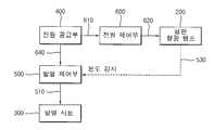
도 2는 도 1에 도시된 전원 공급부로부터 공급된 구동 전원이 인가되는 구조의 일 실시예를 개략적으로 나타낸 블록도이다.FIG. 2 is a block diagram schematically illustrating an embodiment of a structure in which driving power supplied from the power supply unit illustrated in FIG. 1 is applied.
도 3은 도 2에 도시된 발열 제어부를 나타낸 블록도이다.FIG. 3 is a block diagram illustrating the heat generating controller of FIG. 2.
도 4는 도 3에 도시된 발열 제어부를 간단하게 나타낸 회로도이다.FIG. 4 is a circuit diagram briefly illustrating the heat generating controller of FIG. 3.
도 5는 도 1에 도시된 전원 공급부로부터 공급된 구동 전원이 인가되는 구조의 다른 실시예를 개략적으로 나타낸 블록도이다.FIG. 5 is a block diagram schematically illustrating another embodiment of a structure in which driving power supplied from the power supply unit illustrated in FIG. 1 is applied.
도 6은 본 발명의 일 실시예에 따른 액정표시장치를 나타낸 분해 사시도이다.6 is an exploded perspective view illustrating a liquid crystal display according to an exemplary embodiment of the present invention.
<도면의 주요부분에 대한 부호의 설명><Description of the symbols for the main parts of the drawings>
100 : 백라이트 어셈블리 200 : 평판형광램프100: backlight assembly 200: flat fluorescent lamp
300 : 발열 시트400 : 전원 공급부300: heating sheet 400: power supply
500 : 발열 제어부520 : 써미스터500: heat generating control unit 520: thermistor
540 : 감지 온도 전압부550 : 기준 온도 전압부540: sensing temperature voltage section 550: reference temperature voltage section
570 : 스위치부600 : 전원 제어부570: switch unit 600: power control unit
700 : 수납 용기710 : 완충 부재700: storage container 710: buffer member
720 : 확산판730 : 광학 시트720: diffuser plate 730: optical sheet
740 : 제1 몰드750 : 제2 몰드740: first mold 750: second mold
800 : 디스플레이 유닛900 : 탑 샤시800: display unit 900: top chassis
1000 : 액정표시장치1000: liquid crystal display
본 발명은 백라이트 어셈블리 및 이를 갖는 액정표시장치에 관한 것으로, 더욱 상세하게는 평판형광램프의 온도 분포에 따라 발열 시트의 작동을 제어하여 전력이 낭비되는 것을 방지할 수 있는 백라이트 어셈블리 및 이를 갖는 액정표시장치에 관한 것이다.The present invention relates to a backlight assembly and a liquid crystal display having the same. More particularly, the backlight assembly and the liquid crystal display having the same can be controlled by controlling the operation of the heating sheet according to the temperature distribution of the flat fluorescent lamp. Relates to a device.
일반적으로, 액정표시장치는 액체와 고체의 중간적인 특성을 가지는 액정(Liquid Crystal)의 전기, 광학적 특성을 이용하여 영상을 표시하는 평판표시장치의 하나로써, 다른 디스플레이 장치에 비해 얇고 가벼우며, 낮은 구동전압 및 낮은 소비전력을 갖는 장점이 있어, 산업 전반에 걸쳐 광범위하게 사용되고 있다.In general, the liquid crystal display is a flat panel display that displays an image by using the electrical and optical characteristics of the liquid crystal (Liquid Crystal) having the intermediate characteristics of liquid and solid, and is thinner, lighter, and lower than other display devices. There is an advantage of having a driving voltage and low power consumption, which is widely used throughout the industry.
이와 같은 액정표시장치는 영상을 표시하기 위한 액정표시패널이 자체적으로 발광하지 못하는 비발광성 소자이기 때문에 별도의 광을 공급하기 위한 백라이트 어셈블리를 필요로 한다.Such a liquid crystal display device requires a backlight assembly for supplying additional light because the liquid crystal display panel for displaying an image is a non-light emitting device that does not emit light by itself.
백라이트 어셈블리는 광원으로 다양한 종류가 사용된다. 특히, 최근 들어 액정표시장치가 대형화됨에 따라, 넓은 면적에 걸쳐 균일하게 광을 공급할 수 있는 광원으로 평판형광램프가 개발된 바 있다.Various kinds of backlight assemblies are used as light sources. In particular, in recent years, as the liquid crystal display device is enlarged in size, a flat panel fluorescent lamp has been developed as a light source capable of uniformly supplying light over a large area.
평판형광램프는 다수의 방전공간들로 분할된 구조를 가지며, 양 단부에는 평판형광램프의 구동을 위한 전극들이 방전공간들과 교차되도록 형성된 구조를 갖는다. 또한, 평판형광램프는 온도가 40℃ 온도 이상이 되어야 최고 휘도의 약 90% 이상의 휘도를 나타내기 때문에, 초기 점등시 평판형광램프의 온도를 높이기 위하여 평판형광램프의 하부에는 별도의 발열 시트가 배치된다.The planar fluorescent lamp has a structure divided into a plurality of discharge spaces, and both ends have a structure in which electrodes for driving the planar fluorescent lamp cross the discharge spaces. In addition, since the flat fluorescent lamp exhibits about 90% or more of the maximum brightness when the temperature is over 40 ° C, a separate heating sheet is disposed under the flat fluorescent lamp to increase the temperature of the flat fluorescent lamp during initial lighting. do.
그러나, 발열 시트는 평판형광램프의 온도가 40℃에 도달하여 휘도가 안정화되었음에도 불구하고, 계속적으로 발열 시트에 구동 전원이 공급되어 열을 발생시키게 됨으로써, 전력이 추가로 낭비되는 문제점이 있다.However, the heat generating sheet has a problem in that, even though the brightness of the flat fluorescent lamp reaches 40 ° C. and the luminance is stabilized, driving power is continuously supplied to the heat generating sheet to generate heat, thereby further dissipating power.
따라서, 본 발명은 이와 같은 문제점을 감안한 것으로써, 본 발명은 평판형광램프의 온도 분포에 따라 발열 시트의 작동을 제어하여 전력이 낭비되는 것을 방지할 수 있는 백라이트 어셈블리를 제공한다.Accordingly, the present invention has been made in view of such a problem, and the present invention provides a backlight assembly capable of controlling the operation of the heating sheet according to the temperature distribution of the flat fluorescent lamp to prevent waste of power.
또한, 본 발명은 상기한 백라이트 어셈블리를 갖는 액정표시장치를 제공한다.In addition, the present invention provides a liquid crystal display device having the above-described backlight assembly.
상술한 본 발명의 일 특징에 따른 백라이트 어셈블리는 평판형광램프, 발열 시트, 전원 공급부 및 발열 제어부를 포함한다. 상기 평판형광램프는 다수의 방전 공간들로 분할되어 광을 발생한다. 상기 발열 시트는 상기 평판형광램프의 하부에 배치되어 상기 평판형광램프에 열을 공급한다. 상기 전원 공급부는 상기 발열 시트와 연결되어 상기 발열 시트에 구동 전원을 공급한다. 상기 발열 제어부는 상기 평판형광램프의 온도에 따라 상기 발열 시트에 상기 구동 전원을 인가 및 차단하는 발열 제어부를 포함한다.According to an aspect of the present invention, a backlight assembly includes a flat panel fluorescent lamp, a heating sheet, a power supply unit, and a heating control unit. The flat fluorescent lamp is divided into a plurality of discharge spaces to generate light. The heat generating sheet is disposed under the flat fluorescent lamp to supply heat to the flat fluorescent lamp. The power supply unit is connected to the heat generating sheet to supply driving power to the heat generating sheet. The heat generating control unit includes a heat generating control unit for applying and blocking the driving power to the heat generating sheet according to the temperature of the flat fluorescent lamp.
상기 발열 제어부는 상기 평판형광램프의 온도가 기 설정된 기준 온도보다 낮으면, 상기 발열 시트에 상기 구동 전원을 인가하고, 상기 기준 온도보다 높으면, 상기 발열 시트에 인가된 상기 구동 전원을 차단한다. 여기서, 기준 전압은 35℃ 내지 45℃ 범위 내에서 설정된다.The heat generating controller applies the driving power to the heat generating sheet when the temperature of the flat panel fluorescent lamp is lower than a preset reference temperature, and cuts off the driving power applied to the heat generating sheet when the heating temperature is higher than the reference temperature. Here, the reference voltage is set within the range of 35 ° C to 45 ° C.
상기 발열 제어부는 상기 평판형광램프의 온도를 감지하여 제1 전압을 발생시키는 감지 온도 전압부, 상기 기준 온도에 따른 제2 전압을 발생시키는 기준 온도 전압부, 상기 감지 온도 전압부 및 상기 기준 온도 전압부와 연결되며, 상기 제1 전압이 상기 제2 전압보다 높고, 낮음에 따라 서로 다른 제어 신호를 발생하는 전압 비교부 및 상기 제어 신호에 따라 상기 발열 시트에 상기 구동 전원을 인가 및 차단하는 스위치부를 포함한다. 여기서, 상기 감지 온도 전압부는 상기 평판형광램프의 온도를 감지하기 위한 써미스터(Thermistor)를 포함한다.The heat generating controller detects a temperature of the flat fluorescent lamp to generate a first voltage, a sensing temperature voltage unit generating a second voltage according to the reference temperature, a sensing temperature voltage unit, the sensing temperature voltage unit, and the reference temperature voltage. A voltage comparator for generating different control signals as the first voltage is higher and lower than the second voltage, and a switch unit for applying and cutting off the driving power to the heating sheet according to the control signal. Include. Here, the sensing temperature voltage unit includes a thermistor for sensing the temperature of the flat fluorescent lamp.
또한, 백라이트 어셈블리는 상기 구동 전원의 온오프(on/off)를 제어하기 위하여 상기 전원 공급부와 연결된 전원 제어부를 더 포함한다. 여기서, 상기 평판형광램프의 온도가 0℃를 초과하면, 상기 발열 제어부는 상기 전원 제어부와 연결되어 작동하고, 상기 평판형광램프의 온도가 0℃ 이하이면, 상기 발열 제어부는 상 기 전원 공급부와 연결되어 작동한다.The backlight assembly may further include a power control unit connected to the power supply unit to control on / off of the driving power. Here, when the temperature of the flat plate fluorescent lamp exceeds 0 ° C, the heat generating control unit is connected to the power control unit and operates. When the flat plate fluorescent lamp has a temperature of 0 ° C. or less, the heat generating control unit is connected to the power supply unit. It works.
본 발명의 일 특징에 따른 액정표시장치는 광을 공급하는 백라이트 어셈블리 및 상기 백라이트 어셈블리로부터의 광을 이용하여 영상을 표시하는 디스플레이 유닛을 포함한다. 상기 백라이트 어셈블리는 다수의 방전공간들로 분할되어 광을 발생하는 평판형광램프, 상기 평판형광램프의 하부에 배치되어 상기 평판형광램프에 열을 공급하는 발열 시트, 상기 발열 시트와 연결되어 상기 발열 시트에 구동 전원을 공급하는 전원 공급부 및 상기 평판형광램프의 온도에 따라 상기 발열 시트에 상기 구동 전원을 인가 및 차단하는 발열 제어부를 포함한다.A liquid crystal display according to an aspect of the present invention includes a backlight assembly for supplying light and a display unit for displaying an image using light from the backlight assembly. The backlight assembly may include a flat panel fluorescent lamp divided into a plurality of discharge spaces to generate light, a heating sheet disposed below the flat fluorescent lamp to supply heat to the flat panel fluorescent lamp, and connected to the heating sheet to generate the light. And a heat generating controller configured to apply and cut off the driving power to the heat generating sheet according to a temperature of the flat fluorescent lamp.
이러한 백라이트 어셈블리 및 이를 갖는 액정표시장치에 따르면, 백라이트 어셈블리가 평판형광램프의 온도에 따라 발열 시트의 작동을 제어할 수 있는 발열 제어부를 포함함으로써, 전력이 낭비되는 것을 방지할 수 있다.According to such a backlight assembly and a liquid crystal display device having the same, the backlight assembly includes a heat generating controller capable of controlling the operation of the heat generating sheet according to the temperature of the flat panel fluorescent lamp, thereby preventing waste of power.
이하, 첨부한 도면을 참조하여, 본 발명의 바람직한 실시예들을 상세하게 설명하고자 한다.Hereinafter, exemplary embodiments of the present invention will be described in detail with reference to the accompanying drawings.
도 1은 본 발명의 일 실시예에 따른 백라이트 어셈블리를 나타낸 분해 사시도이며, 도 2는 도 1에 도시된 전원 공급부로부터 공급된 구동 전원이 인가되는 구조의 일 실시예를 개략적으로 나타낸 블록도이다.FIG. 1 is an exploded perspective view illustrating a backlight assembly according to an exemplary embodiment of the present invention, and FIG. 2 is a schematic block diagram of an exemplary embodiment in which driving power supplied from the power supply unit illustrated in FIG. 1 is applied.
도 1 및 도 2를 참조하면, 본 발명의 일 실시예에 따른 백라이트 어셈블리(100)는 평판형광램프(200), 발열 시트(300), 전원 공급부(400) 및 발열 제어부(500)를 포함한다.1 and 2, the
평판형광램프(200)는 다수의 방전공간들로 분할되어 광을 발생한다. 평판형 광램프(200)는 전원 공급부(400)로부터 인가된 구동 전원에 반응하여 방전공간들에서 플라즈마 방전을 일으키며, 플라즈마 방전에 의해 발생된 자외선을 가시광으로 변환하여 외부로 출사한다. 여기서, 평판형광램프(200)에는 별도의 전원 공급 장치를 통해 구동 전원이 인가될 수 있다. 또한, 평판형광램프(200)는 일반적으로, 구동 전원을 인가 받기 위하여 길이 방향을 따라 양 단부에 형성된 외부 전극(210)을 포함한다.The flat
발열 시트(300)는 평판형광램프(200)의 하부에 배치된다. 발열 시트(300)는 전원 공급부(400)로부터 인가되는 구동 전원에 반응하여 열을 발생시키며, 발생된 열은 평판형광램프(200)에 공급된다. 이는, 평판형광램프(200)의 초기 점등 시, 평판형광램프(200)가 낼 수 있는 최고 휘도의 약 90%에 해당하는 40℃까지 온도를 높여 휘도가 안정화되는데 걸리는 시간을 단축시키기 위해서이다. 일 예로, 평판형광램프(200)의 온도가 0℃를 초과한다는 가정 하에, 평판형광램프(200)의 초기 점등 시 휘도가 안정화되는데 걸리는 시간은 발열 시트(300)가 부재 시, 약 12분이 소요되는데 비해 발열 시트(300)를 배치하면 약 5분이 소요된다.The
이와 같이, 백라이트 어셈블리(100)는 평판형광램프(200)의 하부에 발열 시트(300)를 배치시킴으로써, 평판형광램프(200)의 초기 점등 시, 휘도가 안정화시키는데 걸리는 시간을 약 58% 감소시킬 수 있다.As such, the
전원 공급부(400)는 발열 시트(300)의 발열을 위한 교류 전원 또는 직류 전원을 출력한다. 한편, 전원 공급부(400)는 외부로부터 인가되는 저전위의 교류 전압을 평판형광램프(200)의 발광에 적합한 고전위의 교류 전압으로 승압하여 평판형 광램프(200)의 발광을 위한 구동 전원을 출력할 수 있다.The
발열 제어부(500)는 발열 시트(300)와 전원 공급부(400) 사이에서, 평판형광램프(200)의 온도에 따라 발열 시트(300)에 구동 전원을 인가 및 차단한다. 발열 제어부(500)는 평판형광램프(200)의 온도가 기 설정된 기준 온도보다 낮으면, 발열 시트(300)에 구동 전원을 제1 라인(510)을 통해 인가하고, 기준 온도보다 높으면, 발열 시트(300)에 인가된 구동 전원을 차단한다. 여기서, 기준 온도는 35℃ 내지 45℃의 범위에서 설정되며, 40℃가 바람직하다. 이는, 평판형광램프(200)의 온도가 40℃에서 최고 휘도의 90% 정도를 낼 수 있기 때문이다.The
발열 제어부(500)는 써미스터(Thermistor, 520)를 통해 평판형광램프(200)의 온도를 감지한다. 써미스터(520)는 평판형광램프(200)와 근접하게 배치되어 온도 감지선(530)을 통해 발열 제어부(500)와 연결된다. 써미스터(520)는 도 3 및 도 4를 참조하여 발열 제어부(500)의 설명 시, 보다 상세하게 설명하고자 한다.The
또한, 백라이트 어셈블리(100)는 구동 전원의 온오프(on/off)를 제어하기 위하여 전원 공급부(400)와 연결된 전원 제어부(600)를 더 포함한다.In addition, the
전원 제어부(600)는 전원 공급부(400)로부터 제2 라인(610)을 통해 인가된 구동 전원을 제3 라인(620) 및 제4 라인(630)을 통해 평판형광램프(200) 및 발열 제어부(500)에 인가한다. 이러한 구조는 평판형광램프(200)의 온도가 0℃를 초과할 경우에 사용된다. 이는, 발열 제어부(500)가 평판형광램프(200)의 점등과 동시에 작동되게 하여 점등 전 불필요한 예열로 인한 전력 낭비를 방지하기 위해서이다. 여기서, 평판형광램프(200)의 초기 온도가 0℃ 이하일 경우는 도 5를 참조하 여 이하에서 설명하고자 한다.The
이러한 전원 제어부(600), 전원 공급부(400) 및 발열 제어부(500)는 도 1에서와 같이 별도로 배치된다. 이와 달리, 전원 제어부(600), 전원 공급부(400) 및 발열 제어부(500)는 동일한 기판 상에 형성될 수 있다.The
또한, 백라이트 어셈블리(100)는 평판형광램프(200) 및 발열 시트(300)를 수납하는 수납 용기(700), 평판형광램프(200)의 가장자리를 지지하는 완충 부재(710), 평판형광램프(200)의 상부에 배치되어 평판형광램프(200)로부터 출사되는 광을 확산시키는 확산판(720), 확산판(720)의 상부에 배치되어 확산판(720)을 통해 확산된 광의 경로를 다시 한번 변경하여 휘도 특성을 향상시키는 광학 시트(730), 평판형광램프(200)의 가장자리를 고정하면서 확산판(720)의 가장자리를 지지하는 제1 몰드(740) 및 제1 몰드(740)의 상부에 배치되어 확산판(720) 및 광학 시트(730)의 가장자리를 고정하는 제2 몰드(750)를 더 포함한다.In addition, the
도 3은 도 2에 도시된 발열 제어부를 나타낸 블록도이며, 도 4는 도 3에 도시된 발열 제어부를 간단하게 나타낸 회로도이다.FIG. 3 is a block diagram illustrating the heat generating controller of FIG. 2, and FIG. 4 is a circuit diagram briefly showing the heat generating controller of FIG. 3.
도 3 및 도 4를 참조하면, 발열 제어부(500)는 감지 온도 전압부(540), 기준 온도 전압부(550), 전압 비교부(560) 및 스위치부(570)를 포함한다.3 and 4, the
본 실시예에서, 발열 제어부(500)에는 전원 제어부(600)와 연결된 제4 라인(630)을 통해 5V의 구동 전압이 일괄적으로 인가된다.In the present exemplary embodiment, a driving voltage of 5V is collectively applied to the
감지 온도 전압부(540)는 평판형광램프(200)의 온도를 감지하기 위한 써미스터(Thermistor, 520)를 포함한다. 써미스터(520)는 온도가 높아지면, 저항이 작아 지는 특징을 갖는다. 이와 같은 특징을 갖는 써미스터(520)를 일반적으로, NTC(Negative Temperature Coefficient) 써미스터라고 하며, 본 발명에서 설명하는 써미스터(520)는 NTC 써미스터를 의미한다.The sensing
써미스터(520)는 25℃에서 약 10㏀의 저항을 갖는다. 써미스터(520)는 과전류 방지, 온도 보상, 온도 감지 등 전자 및 전기의 전반적인 분야에 사용되고 있으며, 그 종류 또한, 다양하다. 여기서, 본 발명의 써미스터(520)는 평판형광램프(200)의 온도 감지에 적합한 박막 형태로 이루어질 수 있다. 이러한 써미스터(520)는 반도체 재질로 이루어진다.
써미스터(520)는 온도 감지선(530)을 통해 평판형광램프(200)의 온도를 감지하여 제1 전압을 발생시킨다. 구체적으로, 제1 전압은 제1 지점(542)에서 인가되며, 써미스터(520)의 저항이 증가함에 따라 낮아진다. 여기서, 감지 온도 전압부(540)는 써미스터(520)의 저항과 비교하기 위하여 제1 지점(542)을 중심으로 써미스터(520)와 대향하도록 배치된 제1 저항(R1)을 더 포함한다. 또한, 감지 온도 전압부(540)에서는 제1 전압을 정밀하게 유지시키기 위하여 제1 전압이 인가된 라인에 10nF의 캐패시터(Capacitor : C1)를 포함한 제1 접지 라인(544)을 연결하여 접지 시킨다.The
기준 온도 전압부(550)는 기준 온도에 따른 제2 전압을 발생시킨다. 기준 온도는 35℃ 내지 45℃이며, 40℃가 바람직하다. 제2 전압은 제2 저항(R2)과 제3 저항(R3) 사이인 제2 지점(552)에서 인가된다. 또한, 기준 온도 전압부(550)에서는 제2 전압을 정밀하게 유지시키기 위하여 제2 전압이 인가된 라인에 10nF의 캐패 시터(C2)를 포함한 제2 접지 라인(554)을 연결하여 접지 시킨다.The reference
전압 비교부(560)는 감지 온도 전압부(540) 및 기준 온도 전압부(550)와 연결된다. 전압 비교부(560)는 제1 전압이 제2 전압보다 높고, 낮음에 따라 서로 다른 제어 신호를 발생하는 비교기(562)를 포함한다. 즉, 비교기(562)는 제1 전압이 제2 전압보다 낮으면 하이(High) 신호를 발생하고, 제1 전압이 제2 전압보다 높으면 로우(Low) 신호를 발생한다. 이는, 제1 전압이 평판형광램프(200)의 온도가 증가할수록 높아지기 때문이다. 여기서, 제1 전압과 평판형광램프(200)의 온도와의 상관 관계를 간단하게 설명하면, 평판형광램프(200)의 온도가 증가함에 따라, 써미스터(520)의 저항은 작아지게 되고, 작아지게 된 저항은 제1 저항(R1)과 상대적으로 비교됨으로써, 결과적으로 제1 전압은 증가하게 된다.The
스위치부(570)는 전압 비교부(560)에서 발생된 하이 및 로우 신호에 따라 발열 시트(300)에 구동 전원을 인가 및 차단한다. 즉, 스위치부(570)에 하이 신호가 인가되면, 발열 시트(300)에 구동 전원을 인가하고, 로우 신호가 인가되면, 발열 시트(300)에 인가된 구동 전원을 차단한다.The
스위치부(570)는 게이트 전극(582), 소오스 전극(584) 및 드레인 전극(586)으로 이루어진 트랜지스터(transistor, 580)를 포함한다. 게이트 전극(582)에는 전압 비교부(560)에서 발생된 제어 신호인 하이 및 로우 신호가 인가된다. 소오스 전극(584)에는 전원 제어부(600)로부터 제4 라인(630)을 통해 구동 전원이 인가된다. 드레인 전극(586)에는 제1 라인(510)을 통해 발열 시트(300)와 연결된다. 이러한 스위치부(570)에서는 게이트 전극(582)에 인가된 하이 및 로우 신호에 따라 소오스 전극(584)과 드레인 전극(586), 즉 전원 제어부(600) 및 발열 시트(300)를 연결 및 차단시키게 된다.The
이와 같이, 발열 제어부(500)는 평판형광램프(200)의 온도를 감지하여 제1 전압을 발생시키고, 기 설정된 기준 온도에 따라 제2 전압을 발생시켜, 제1 전압이 제2 전압을 비교하여 발열 시트(300)와 전원 제어부(600)를 연결 및 차단시킴으로써, 발열 시트(300)의 작동을 제어할 수 있다.As described above, the
도 5는 도 1에 도시된 전원 공급부로부터 공급된 구동 전원이 인가되는 구조의 다른 실시예를 개략적으로 나타낸 블록도이다.FIG. 5 is a block diagram schematically illustrating another embodiment of a structure in which driving power supplied from the power supply unit illustrated in FIG. 1 is applied.
도 5를 참조하면, 평판형광램프(200)의 초기 온도가 0℃ 이하이면, 발열 제어부(500)는 전원 공급부(400)와 제2 라인(610)에 의해 연결되어 전원 제어부(600)와는 별개로 작동한다.Referring to FIG. 5, when the initial temperature of the flat panel
이와 같은 구조에서 발열 시트(300)는 평판형광램프(200)의 비점등 시에도 전원 공급부(400)로부터 전원 인가선(640)을 통해 구동 전원이 인가되어 항시 열을 발생하게 된다. 이는, 평판형광램프(200)의 초기 온도가 0℃ 이하로 매우 낮음으로 인하여, 휘도가 안정화되는데 상대적으로 매우 긴 시간이 소요되기 때문이다.In such a structure, the
따라서, 발열 시트(300)는 0℃ 이하의 온도를 가진 평판형광램프(200)가 점등되기 이전에 소정의 시간동안 예열을 실시한 후, 평판형광램프(200)의 온도가 기준 온도 이상이 되면, 발열 시트(300)에 구동 전원이 인가되는 것을 차단함으로써, 전력이 낭비되는 것을 방지할 수 있다.Therefore, after the preheating
도 6은 본 발명의 일 실시예에 따른 액정표시장치를 나타낸 분해 사시도이 다.6 is an exploded perspective view illustrating a liquid crystal display according to an exemplary embodiment of the present invention.
도 6을 참조하면, 본 발명의 일 실시예에 따른 액정표시장치(1000)는 광을 공급하는 백라이트 어셈블리(100) 및 영상을 표시하는 디스플레이 유닛(800)을 포함한다.Referring to FIG. 6, the
백라이트 어셈블리(100)는 도 1 내지 도 5에 도시된 것과 동일한 구성을 가지므로, 동일한 참조 번호를 사용하며, 그 중복되는 상세한 설명은 생략하기로 한다.Since the
디스플레이 유닛(800)은 백라이트 어셈블리(100)로부터 공급되는 광을 이용하여 영상을 표시하는 액정표시패널(810) 및 액정표시패널(810)을 구동하기 위한 구동 회로부(820)를 포함한다.The display unit 800 includes a liquid
액정표시패널(810)은 제1 기판(812), 제1 기판(812)과 대향하여 결합되는 제2 기판(814) 및 제1 기판(812)과 제2 기판(814) 사이에 개재된 액정층(816)을 포함한다.The liquid
제1 기판(812)은 스위칭 소자인 박막 트랜지스터(580)(Thin Film Transistor : 이하, TFT라 칭함)가 매트릭스 형태로 형성된 TFT 기판이다. 상기 TFT들의 소오스 단자 및 게이트 단자에는 각각 데이터 라인 및 게이트 라인이 연결되고, 드레인 단자에는 투명한 도전성 재질로 이루어진 화소 전극이 연결된다.The
제2 기판(814)은 색을 구현하기 위한 RGB 화소가 박막 형태로 형성된 칼라필터 기판이다. 제2 기판(814)에는 투명한 도전성 재질로 이루어진 공통 전극이 형성된다.The
이러한 구성을 갖는 액정표시패널(810)은 상기 TFT의 게이트 단자에 전원이 인가되어 TFT가 턴-온(Turn on)되면, 화소 전극과 공통 전극 사이에는 전계가 형성된다. 이러한 전계에 의해 제1 기판(812)과 제2 기판(814) 사이에 개재된 액정층(816)의 액정 분자들의 배열이 변화되고, 액정 분자들의 배열 변화에 따라서 백라이트 어셈블리(100)로부터 공급되는 광의 투과도가 변경되어 원하는 계조의 영상을 표시하게 된다.In the liquid
구동 회로부(820)는 액정표시패널(810)에 데이터 구동신호를 공급하는 데이터 인쇄회로기판(822), 액정표시패널(810)에 게이트 구동신호를 공급하는 게이트 인쇄회로기판(824), 데이터 인쇄회로기판(822)을 액정표시패널(810)에 연결하는 데이터 구동회로필름(826) 및 게이트 인쇄회로기판(824)을 액정표시패널(810)에 연결하는 게이트 구동회로필름(828)을 포함한다.The driving
데이터 구동회로필름(826) 및 게이트 구동회로필름(828)은 예를 들어, 테이프 캐리어 패키지(Tape Carrier Package : TCP) 또는 칩 온 필름(Chip On Film : COF)으로 이루어진다. 한편, 게이트 인쇄회로기판(824)은 액정표시패널(810) 및 게이트 구동회로필름(828)에 별도의 신호 배선을 형성함으로써, 제거되어질 수 있다.The data driving
한편, 액정표시장치(1000)는 디스플레이 유닛(800)을 고정하기 위한 탑 샤시(900)를 더 포함할 수 있다. 탑 샤시(900)는 수납 용기(700)와 결합되어 액정표시패널(810)의 가장자리를 고정한다. 이때, 데이터 인쇄회로기판(822)은 데이터 구동회로필름(826)에 의해 밴딩되어 수납 용기(700)의 측면 또는 배면에 고정된다. 탑 샤시(900)는 일 예로, 변형이 적고 강도가 우수한 금속으로 이루어진다.The
이와 같은 백라이트 어셈블리 및 이를 갖는 액정표시장치에 따르면, 발열 제어부는 써미스터를 이용하여 평판형광램프의 온도를 감지하고, 감지된 온도가 기준 온도보다 낮으면, 발열 시트에 구동 전원을 인가하여 발열시키고, 기준 온도보다 높으면, 발열 시트에 구동 전원이 인가되는 것을 차단하여 발열하지 못하게 함으로써, 전력이 낭비되는 것을 방지할 수 있다.According to such a backlight assembly and a liquid crystal display having the same, the heating controller senses the temperature of the flat fluorescent lamp using the thermistor, and if the detected temperature is lower than the reference temperature, the driving unit generates heat by applying driving power to the heating sheet. If the temperature is higher than the reference temperature, it is possible to prevent the power from being wasted by blocking the application of the driving power to the heat generating sheet so as not to generate heat.
앞서 설명한 본 발명의 상세한 설명에서는 본 발명의 바람직한 실시예들을 참조하여 설명하였지만, 해당 기술분야의 숙련된 당업자 또는 해당 기술분야에 통상의 지식을 갖는 자라면 후술될 특허청구범위에 기재된 본 발명의 사상 및 기술 영역으로부터 벗어나지 않는 범위 내에서 본 발명을 다양하게 수정 및 변경시킬 수 있음을 이해할 수 있을 것이다.In the detailed description of the present invention described above with reference to the preferred embodiments of the present invention, those skilled in the art or those skilled in the art having ordinary skill in the art will be described in the claims to be described later It will be understood that various modifications and variations can be made in the present invention without departing from the scope of the present invention.
Claims (10)
Translated fromKoreanPriority Applications (1)
| Application Number | Priority Date | Filing Date | Title |
|---|---|---|---|
| KR1020060001961AKR20070074166A (en) | 2006-01-06 | 2006-01-06 | Back light assembly and liquid crystal display device having same |
Applications Claiming Priority (1)
| Application Number | Priority Date | Filing Date | Title |
|---|---|---|---|
| KR1020060001961AKR20070074166A (en) | 2006-01-06 | 2006-01-06 | Back light assembly and liquid crystal display device having same |
Publications (1)
| Publication Number | Publication Date |
|---|---|
| KR20070074166Atrue KR20070074166A (en) | 2007-07-12 |
Family
ID=38508379
Family Applications (1)
| Application Number | Title | Priority Date | Filing Date |
|---|---|---|---|
| KR1020060001961AWithdrawnKR20070074166A (en) | 2006-01-06 | 2006-01-06 | Back light assembly and liquid crystal display device having same |
Country Status (1)
| Country | Link |
|---|---|
| KR (1) | KR20070074166A (en) |
Cited By (1)
| Publication number | Priority date | Publication date | Assignee | Title |
|---|---|---|---|---|
| KR101407899B1 (en)* | 2012-11-27 | 2014-06-13 | 이피네트시스템즈 주식회사 | Lcd display apparatus |
- 2006
- 2006-01-06KRKR1020060001961Apatent/KR20070074166A/ennot_activeWithdrawn
Cited By (1)
| Publication number | Priority date | Publication date | Assignee | Title |
|---|---|---|---|---|
| KR101407899B1 (en)* | 2012-11-27 | 2014-06-13 | 이피네트시스템즈 주식회사 | Lcd display apparatus |
Similar Documents
| Publication | Publication Date | Title |
|---|---|---|
| US7511435B2 (en) | Backlight unit and liquid crystal display device having the same | |
| US7969404B2 (en) | Device for driving a backlight, backlight assembly, LCD apparatus having the same and method for driving a backlight | |
| KR101233819B1 (en) | Apparatus for driving lamp and liquid crystal display having the same | |
| US7595785B2 (en) | Display device and driving device for a light source | |
| US7868972B2 (en) | Light source unit, liquid crystal display having the same, and method thereof | |
| CN1988743A (en) | Device for driving light emitting diode | |
| CN1956045B (en) | Backlight unit and driving method thereof | |
| KR101164199B1 (en) | Inverter circuit, backlight device, and liquid crystal display device using the same | |
| KR101205535B1 (en) | Apparatus for driving of light source and display device having the same and method of driving of light source | |
| KR101061847B1 (en) | Power supply and backlight unit | |
| KR20070074166A (en) | Back light assembly and liquid crystal display device having same | |
| KR20080021305A (en) | LCD Display | |
| KR102217673B1 (en) | Circuit and method for driving backlight and liquid crystal display device including the same | |
| KR101192058B1 (en) | Lamp Driving Device and Driving Method thereof | |
| KR20080034294A (en) | Backlight unit and liquid crystal display including the same | |
| KR20070000639A (en) | Backlight assembly and flat panel display device having the same | |
| KR20060065169A (en) | Back light assembly and liquid crystal display device having same | |
| KR101448907B1 (en) | Backlight unit and liquid crystal display comprising the same | |
| KR20060047027A (en) | Driving device and display device of light source for display device | |
| KR20060070347A (en) | Backlight Device and Display Device | |
| US20080158135A1 (en) | Backlight assembly, method of driving the same, and liquid crystal display having the same | |
| KR20050019194A (en) | Back light assembly and liquid crystal display having the same | |
| KR20070093260A (en) | Back light assembly and liquid crystal display including the same | |
| KR20050019283A (en) | Heat emitting apparatus for fluorescent lamp, back light assembly and liquid crystal display device including the same | |
| KR20060064826A (en) | Flat Panel Display Improves Heat Dissipation Efficiency |
Legal Events
| Date | Code | Title | Description |
|---|---|---|---|
| PA0109 | Patent application | Patent event code:PA01091R01D Comment text:Patent Application Patent event date:20060106 | |
| PG1501 | Laying open of application | ||
| PC1203 | Withdrawal of no request for examination | ||
| WITN | Application deemed withdrawn, e.g. because no request for examination was filed or no examination fee was paid |