KR20070059666A - Method and apparatus for controlling power in time division duplex communication system - Google Patents
Method and apparatus for controlling power in time division duplex communication systemDownload PDFInfo
- Publication number
- KR20070059666A KR20070059666AKR1020050118762AKR20050118762AKR20070059666AKR 20070059666 AKR20070059666 AKR 20070059666AKR 1020050118762 AKR1020050118762 AKR 1020050118762AKR 20050118762 AKR20050118762 AKR 20050118762AKR 20070059666 AKR20070059666 AKR 20070059666A
- Authority
- KR
- South Korea
- Prior art keywords
- power
- power control
- uplink
- communication system
- tdd
- Prior art date
- Legal status (The legal status is an assumption and is not a legal conclusion. Google has not performed a legal analysis and makes no representation as to the accuracy of the status listed.)
- Ceased
Links
Images


Classifications
- H—ELECTRICITY
- H04—ELECTRIC COMMUNICATION TECHNIQUE
- H04W—WIRELESS COMMUNICATION NETWORKS
- H04W52/00—Power management, e.g. Transmission Power Control [TPC] or power classes
- H04W52/04—Transmission power control [TPC]
- H04W52/06—TPC algorithms
- H04W52/14—Separate analysis of uplink or downlink
- H04W52/146—Uplink power control
- H—ELECTRICITY
- H04—ELECTRIC COMMUNICATION TECHNIQUE
- H04L—TRANSMISSION OF DIGITAL INFORMATION, e.g. TELEGRAPHIC COMMUNICATION
- H04L5/00—Arrangements affording multiple use of the transmission path
- H04L5/14—Two-way operation using the same type of signal, i.e. duplex
- H—ELECTRICITY
- H04—ELECTRIC COMMUNICATION TECHNIQUE
- H04W—WIRELESS COMMUNICATION NETWORKS
- H04W52/00—Power management, e.g. Transmission Power Control [TPC] or power classes
- H04W52/04—Transmission power control [TPC]
- H04W52/18—TPC being performed according to specific parameters
- H04W52/24—TPC being performed according to specific parameters using SIR [Signal to Interference Ratio] or other wireless path parameters
- H04W52/242—TPC being performed according to specific parameters using SIR [Signal to Interference Ratio] or other wireless path parameters taking into account path loss
- H—ELECTRICITY
- H04—ELECTRIC COMMUNICATION TECHNIQUE
- H04W—WIRELESS COMMUNICATION NETWORKS
- H04W52/00—Power management, e.g. Transmission Power Control [TPC] or power classes
- H04W52/04—Transmission power control [TPC]
- H04W52/18—TPC being performed according to specific parameters
- H04W52/24—TPC being performed according to specific parameters using SIR [Signal to Interference Ratio] or other wireless path parameters
- H04W52/243—TPC being performed according to specific parameters using SIR [Signal to Interference Ratio] or other wireless path parameters taking into account interferences
- H—ELECTRICITY
- H04—ELECTRIC COMMUNICATION TECHNIQUE
- H04W—WIRELESS COMMUNICATION NETWORKS
- H04W52/00—Power management, e.g. Transmission Power Control [TPC] or power classes
- H04W52/04—Transmission power control [TPC]
- H04W52/18—TPC being performed according to specific parameters
- H04W52/24—TPC being performed according to specific parameters using SIR [Signal to Interference Ratio] or other wireless path parameters
- H04W52/248—TPC being performed according to specific parameters using SIR [Signal to Interference Ratio] or other wireless path parameters where transmission power control commands are generated based on a path parameter
- Y—GENERAL TAGGING OF NEW TECHNOLOGICAL DEVELOPMENTS; GENERAL TAGGING OF CROSS-SECTIONAL TECHNOLOGIES SPANNING OVER SEVERAL SECTIONS OF THE IPC; TECHNICAL SUBJECTS COVERED BY FORMER USPC CROSS-REFERENCE ART COLLECTIONS [XRACs] AND DIGESTS
- Y02—TECHNOLOGIES OR APPLICATIONS FOR MITIGATION OR ADAPTATION AGAINST CLIMATE CHANGE
- Y02D—CLIMATE CHANGE MITIGATION TECHNOLOGIES IN INFORMATION AND COMMUNICATION TECHNOLOGIES [ICT], I.E. INFORMATION AND COMMUNICATION TECHNOLOGIES AIMING AT THE REDUCTION OF THEIR OWN ENERGY USE
- Y02D30/00—Reducing energy consumption in communication networks
- Y02D30/70—Reducing energy consumption in communication networks in wireless communication networks
Landscapes
- Engineering & Computer Science (AREA)
- Signal Processing (AREA)
- Computer Networks & Wireless Communication (AREA)
- Mobile Radio Communication Systems (AREA)
Abstract
Translated fromKoreanDescription
Translated fromKorean도 1은 종래의 무선통신시스템의 구성 장치 사이의 접속 관계를 나타내는 도면,1 is a diagram showing a connection relationship between components of a conventional wireless communication system;
도 2는 종래의 TDD-CDM/CDMA 통신시스템에서 기지국과 단말기 사이의 상향링크와 하향링크의 구조를 나타내는 도면,2 is a view showing a structure of uplink and downlink between a base station and a terminal in a conventional TDD-CDM / CDMA communication system;
도 3은 종래의 TDD-CDM/CDMA 통신 시스템의 상향 링크 신호 전송에 대한 개루프 전력제어와 폐루프 전력제어 절차를 나타내는 도면,3 is a diagram illustrating an open loop power control and closed loop power control procedure for uplink signal transmission in a conventional TDD-CDM / CDMA communication system;
도 4는 본 발명에 따른 TDD-OFDM 방식의 통신시스템에서 하향링크 프레임과 상향링크 프레임의 구성을 나타내는 도면,4 is a diagram illustrating a configuration of a downlink frame and an uplink frame in a TDD-OFDM communication system according to the present invention;
도 5는 본 발명에 따른 TDD-OFDMA 통신 시스템의 하향링크 프레임과 상향링크 프레임의 구성을 나타내는 도면,5 is a diagram illustrating the configuration of a downlink frame and an uplink frame in a TDD-OFDMA communication system according to the present invention;
도 6은 종래의 방법으로 한 사용자가 일정 시간 이상 지속적으로 상향링크의 한 채널을 사용하는 경우의 개루프 전력 제어와 폐루프 전력제어를 나타내는 도면,FIG. 6 is a diagram illustrating open loop power control and closed loop power control when a user continuously uses one channel of an uplink for a predetermined time or more by the conventional method; FIG.
도 7은 본 발명에서 사용자들이 상향링크의 한 채널을 함께 사용하는 경우의 개루프 전력 제어를 나타내는 도면,FIG. 7 is a diagram illustrating open loop power control when users use one channel of uplink together in the present invention;
도 8은 본 발명에 따라 TDD-OFDM/OFDMA 시스템에서 기지국과 단말기 사이의 상향링크와 하향링크의 구조를 나타내는 도면,8 is a diagram showing the structure of uplink and downlink between a base station and a terminal in a TDD-OFDM / OFDMA system according to the present invention;
도 9는 본 발명에 따른 통신 시스템에서 기지국-단말기 사이의 송신 및 수신 과정에서의 전력 제어 과정을 나타내는 도면,9 is a diagram illustrating a power control process in a transmission and reception process between a base station and a terminal in a communication system according to the present invention;
도 10은 본 발명에 따른 단말기에서의 전력 제어 과정에 대한 흐름도,10 is a flowchart illustrating a power control process in a terminal according to the present invention;
도 11은 본 발명에 따른 전력 제어 방법을 구현하는 단말기 구성을 나타내는 도면.11 is a diagram illustrating a terminal configuration for implementing a power control method according to the present invention;
본 발명은 시분할 듀플렉스(TDD: Time Division Duplex) 통신 시스템의 전력 제어 방법 및 장치에 관한 것이다. 구체적으로는 이전 프레임의 전력 제어 계산 요소 및 전력 증감 변화량을 사용하여 현재 프레임의 전력 제어 계산 요소를 구하고, 이를 사용하여 상향 링크 전력 값을 결정하는 상향 링크 전력 결정부 및 상기 상향 링크 전력 결정부로부터의 상기 상향 링크 전력 값을 송신부로 전송하여 상향 링크 전력을 제어하는 상향 링크 전력 제어부를 포함하는 시분할 듀플렉스(TDD: Time Division Duplex) 통신 시스템의 전력 제어 장치 및 이의 방법에 관한 것이다.The present invention relates to a power control method and apparatus for a time division duplex (TDD) communication system. Specifically, from the uplink power determiner and the uplink power determiner that obtains the power control computed element of the current frame using the power control computed element and power increase / decrease change amount of the previous frame and uses the same to determine the uplink power value. The present invention relates to a power control apparatus for a time division duplex (TDD) communication system including an uplink power control unit for transmitting an uplink power value to a transmitter to control uplink power.
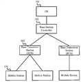
도 1은 일반적인 무선통신시스템의 구성 장치 사이의 접속 관계를 나타내는 도면이다. 무선통신시스템은 코어 네트워크(Core Network)(101)와 기지국제어장치 (BSC: Base Station Controller)(102), 기지국(BTS: Base Transceiver Station))(103), 단말기(MS)(104)로 구성되어 있다. 코어 네트워크(Core Network)(101)는 단말기 위치 관리, 인증, 호(Call) 연결 등의 역할을 담당한다. 기지국제어장치는 자신과 연결된 기지국에 할당될 무선자원을 통제하는 역할을 한다. 기지국(103)은 단말기(104)와 데이터를 통신을 수행한다. 1 is a diagram illustrating a connection relationship between components of a general wireless communication system. The wireless communication system is composed of a core network (101), a base station controller (BSC: 102), a base station (BTS: Base Transceiver Station) (103), and a terminal (MS) 104. It is. The
도 2는 TDD-CDM(Code Division Multiplexing)/CDMA(Code Division Multiple Access) 통신시스템에서 기지국과 단말기 사이의 상향링크와 하향링크의 구조를 나타내는 도면이다. 도 2에서 가로축은 시간 영역을 나타내고, 세로축은 주파수 영역을 나타낸다. 단말기로부터 기지국으로의 상향링크(Uplink)와 기지국으로부터 단말기로의 하향링크(Downlink)의 데이터 전송을 구분하는 방식 중의 하나인 시분할 듀플렉스(TDD: Time Division Duplex)는 상향링크와 하향링크는 동일한 주파수 대역을 사용하고 시간을 분할하여 상향링크와 하향링크를 구분한다. 즉 상향링크 신호가 존재하는 시간 구간과 하향링크 신호가 존재하는 시간 구간이 미리 정의되어 있어서 상향링크 신호와 하향링크 신호는 미리 정해진 각각의 시간 구간 동안에만 통신이 허용된다. 따라서 기지국과 단말기 사이의 통신은 하향링크(Downlink)(201)와 상향링크(Uplink)(202)의 프레임(frame)이 교대로 반복된다. 여기에서 하향링크가 끝나면 상향링크를 위한 시간구간이 할당되는데, 하향링크와 상향링크 사이에는 어떤 신호도 존재하지 않는 전송갭(transmission gap)(204)이 존재한다. 이는 상향링크와 하향링크가 같은 주파수 대역을 공유하므로 상향링크 신호와 하향링크 신호간의 간섭을 방지하기 위한 것이다. 하향링크 채널의 프레임(Frame) 앞부분은 시스 템 정보를 전송하는 브로드캐스트(Broadcast)(공통) 채널(203)이 존재한다. Broadcast 채널 다음에는 사용자들에게 데이터를 전송하는데 사용하는 트래픽(Traffic) 채널들을 코드 영역으로 구분하여 나타낸다. 상향링크 채널의 프레임은 각 사용자에게 할당된 코드 영역(205, 206)으로 구분된다. 각 단말기는 기지국으로부터 자신의 트래픽 채널에 할당된 코드영역을 통해 하향 링크 데이터를 수신하고, 기지국으로 상향 링크 데이터를 전송한다.2 is a diagram illustrating a structure of uplink and downlink between a base station and a terminal in a code division multiplexing (TDD-CDM) / code division multiple access (CDMA) communication system. In FIG. 2, the horizontal axis represents the time domain and the vertical axis represents the frequency domain. Time division duplex (TDD), which is a method of distinguishing uplink and downlink data transmission from the base station to the terminal, is the same frequency band in the uplink and the downlink. And divides uplink and downlink by dividing time. That is, since the time interval in which the uplink signal is present and the time interval in which the downlink signal is present are predefined, communication of the uplink signal and the downlink signal is allowed only during each predetermined time interval. Therefore, in the communication between the base station and the terminal, the frames of the
전력제어는 단말기와 기지국 간의 신호 전송에 사용하는 전력을 제어하여 수신하는 신호의 신호대간섭비(SIR: Signal to Interference Ratio)가 목표치를 유지하도록 하는 것을 말한다. 이하에서는 단말기에서 기지국으로 신호를 전송하는 상향 링크의 경우를 예로 들어 설명한다.Power control refers to controlling the power used for signal transmission between the terminal and the base station to maintain a signal-to-interference ratio (SIR) of a received signal. Hereinafter, an example of an uplink for transmitting a signal from a terminal to a base station will be described.
단말기를 파워 온(power on)하여 처음으로 기지국으로 신호를 전송하는 최초 상향 링크의 경우의 전력 제어를 개루프 전력제어(Open Loop Power Control)라 한다. 최초 상향 링크 발생 전에 기지국은 송신 신호의 전력을 메시지를 통해 단말기에게 알려주고 단말기는 수신신호의 전력을 측정하여 경로 감쇄(path loss)량을 추정하여, 이 경로 감쇄량을 감안하여 최초 상향 링크의 신호 전송에 요구되는 전력을 제어한다.Power control in the first uplink that powers a terminal and transmits a signal to a base station for the first time is called open loop power control. Before the first uplink occurs, the base station informs the terminal of the power of the transmitted signal through a message, and the terminal estimates the path loss by measuring the power of the received signal, and transmits the first uplink signal in consideration of the path attenuation. Control the power required for
위의 개루프 전력의 크기는 아래의 <수학식 1>과 같이 계산한다.The magnitude of the open loop power is calculated as in

여기에서


개루프 전력제어에 따른 최초 상향 링크 전송이후부터의 상향 링크 신호에 대한 전력제어는 기지국으로부터의 지시에 따라 수행한다. 이를 폐루프 전력제어(Closed Loop Power Control)리고 한다. 즉, 기지국이 단말기로부터 수신한 신호 SIR을 계산한 후 이 값을 각 단말기들마다 설정된 목표 신호대간섭비(target SIR)와 비교하여, 목표 값보다 작으면 단말기에게 전력증가의 신호를 보내고, 목표 값보다 크면 전력감소의 신호를 보낸다. 이렇게 함으로써 단말기는 송신 전력을 제어한다.Power control on the uplink signal from the first uplink transmission according to the open loop power control is performed according to an instruction from the base station. This is called closed loop power control. That is, the base station calculates the signal SIR received from the terminal and compares this value with the target signal-to-interference ratio (target SIR) set for each terminal, and if it is smaller than the target value, sends a signal of increasing power to the terminal. If greater, it signals a power reduction. In so doing, the terminal controls the transmit power.
도 3은 TDD-CDM/CDMA 통신 시스템의 상향 링크 신호 전송에 대한 개루프 전력제어와 폐루프 전력제어 절차를 나타내는 도면이다. 먼저 단말기는 하향링크(PCCPCH)(301) 파일럿 신호의 전력을 측정한다(302). 호 설정(Call setup)이 이루어지기 전에 무선 베어러 셋업(Radio bearer setup)(304)이 이루어지며 물리계층을 초기화 한다(305). 호설정이 완료되면 단말기는 첫 상향링크 프레임을 계산된 개루프 전력의 크기 (307)로 송신한다(306)(개루프 전력 제어). 기지국은 프레임을 수신한 후 SIR을 측정하여 target SIR과 비교한 후 전력제어명령(TPC)을 단말기에 피드백한다(308). 단말기는 전력제어명령(TPC)에 따라 일정량의 전력을 높이거나 낮추어 다음 데이터 프레임을 전송한다(309)(폐루프 전력 제어).3 is a diagram illustrating an open loop power control and closed loop power control procedure for uplink signal transmission in a TDD-CDM / CDMA communication system. First, the terminal measures the power of the downlink (PCCPCH) 301 pilot signal (302). Before the call setup is performed, the
이러한 전력 제어 방식은 여러 단말기들이 동일한 전송 주파수 대역에 서로 다른 확산 코드를 사용하여 기지국과 데이터를 송신 및 수신하며, 이때 각 단말기들의 송신 채널은 확산 코드에 의해 구별된다. 그런데 동일한 전송 주파수 대역 내에 여러 개의 채널이 존재하는 경우에 특정 채널의 송신전력이 지나치게 높을 때에는 다른 채널(사용자)에게는 치명적인 간섭으로 작용한다. 따라서 기지국은 모든 채널 사용자들의 신호를 수신하고 이를 각각 통제해야 하며, 이를 위해 각 사용자에 대해 기지국이 판단한 전력제어 정보를 별도의 채널을 통하여 전송해야 하는 문 제가 있다. 또한, 빠르고 정확한 전력 제어를 위해서는 호(Call)가 연결되어 있는 동안에도 실시간, 실질적인 변화량에 대한 폐루프 전력 제어 방식이 필요한 데, 이를 구현하기 위해서는 많은 오버헤드(overhead)가 필요하므로, 기존의 시스템에서는 기지국(BS)이 초기 호설정(call setup)시 특정한 값의 고정된 전력 변화량 단위를 각 단말기에 전송한 뒤, 호가 연결되어 있는 동안에는 이에 대한 증/감의 신호만을 전송하는 방식의 전력제어만이 가능하였다. 따라서 일시에 큰 폭으로 채널 변화가 발생했다고 해도 그 변화에 대한 전력 제어가 어려운 문제가 있다.In this power control scheme, several terminals transmit and receive data with a base station using different spreading codes in the same transmission frequency band, where transmission channels of the respective terminals are distinguished by spreading codes. However, when several channels exist in the same transmission frequency band, when a transmission power of a specific channel is too high, it acts as a fatal interference to another channel (user). Therefore, the base station needs to receive the signals of all the channel users and control them individually, and for this purpose, there is a problem of transmitting power control information determined by the base station for each user through a separate channel. In addition, fast and accurate power control requires a closed-loop power control method for real-time and substantial changes even while a call is connected, which requires a lot of overhead to implement the existing system. In the base station (BS) transmits a fixed unit of power change of a specific value at the initial call setup to each terminal, and only the power control method of transmitting only the increase / decrease signal for the call while the call is connected This was possible. Therefore, even if a large channel change occurs at a time, there is a problem that power control of the change is difficult.
한편, 위와 같은 방식의 전력 제어는 상향링크의 한 채널이 한 사용자에 의해서 일정시간 이상 지속적(Continuously)으로 점유되는 경우에 가능한 방법이다. 도 6은 이와 같이 한 사용자가 일정 시간 이상 지속적으로 상향링크의 한 채널을 사용하는 경우의 개루프 전력 제어와 폐루프 전력제어가 가능함을 나타내는 도면이다. 이 경우에 단말기는 채널별 귀환(feedback) 정보(608,609)를 활용한 폐루프 전력 제어(Closed loop power control)가 가능하다.On the other hand, power control in the above manner is possible when one channel of the uplink is continuously occupied by a user for a predetermined time or more. FIG. 6 is a diagram illustrating an open loop power control and a closed loop power control when a user continuously uses one channel of an uplink for a predetermined time or more. In this case, the terminal may perform closed loop power control using
그러나 차세대 무선 통신 시스템은 짧은 시간 내에 대량의 정보 전달이 가능한 데, 대량 데이터의 지속적인 전송이 필요 없는 음성 통신 채널과 같은 경우에는 하나의 채널을 여러 사용자 단말기가 시간적으로 분리하여 점유할 필요가 있다. 그러나 이러한 경우 상기의 종래의 방법으로는 한 사용자 단말기의 상향링크 신호가 지속적으로 기지국으로부터의 하향 링크를 통해 수신한 귀환 정보를 해당 사용자의 다음 상향 데이터 송신시 폐루프 전력제어를 위해 사용할 수 없고, 전력 제어의 대상이 되는 전송 프레임이 동일한 채널을 통하여 지속적으로 전송되지 않고 시간에 따라 다른 채널을 통하여 전송되어 불연속적(noncontinuous)이므로 이 시간동안 전송 채널 상황이 일시에 크게 변화하는 문제가 있다. 즉, 이러한 경우에는 기지국이 각 단말기로 전력제어 명령을 할 수 없어 폐류프 전력제어가 가능하지 않다.However, the next generation wireless communication system can transfer a large amount of information in a short time, and in the case of a voice communication channel that does not require continuous transmission of a large amount of data, it is necessary to segregate and occupy one channel in time. However, in this case, the conventional method cannot use the feedback information received by the uplink signal of one user terminal through the downlink from the base station for the closed loop power control at the next uplink data transmission of the user. Since the transmission frame, which is the object of power control, is not continuously transmitted through the same channel but is transmitted through different channels according to time, it is non-continuous, and thus, the transmission channel situation changes greatly at this time. That is, in this case, the base station cannot give power control commands to each terminal, so closed-loop power control is not possible.
따라서 대량 데이터의 지속적인 전송이 필요 없는 음성 통신 채널과 같이 한 채널을 여러 사용자가 시간적으로 분리하여 점유하는 불연속적인 상향 링크 채널에 대하여, 별도의 귀환 값을 필요로 하지 않으면서, 정확한 전력 제어 값 업데이트가 가능한 전력제어방법 및 장치가 필요하다.Therefore, for discontinuous uplink channels where multiple users occupy one channel in time, such as voice communication channels that do not require continuous transmission of large amounts of data, accurate power control values are updated without requiring a separate feedback value. There is a need for a power control method and apparatus.
또한, 호가 연결되어 있는 동안에도 실질적인 채널 변화량에 해당하는 변수 값을 전력제어에 적용할 수 있는 전력 제어 장치 및 방법이 요구된다.There is also a need for a power control apparatus and method that can apply a variable value corresponding to a substantial amount of channel change to power control while a call is connected.
본 발명의 목적은 한 채널을 여러 사용자가 시간적으로 분리하여 사용하는 불연속적인 상향 링크 채널에 대하여 정확한 전력 값 제어가 가능한 전력 제어 장치 및 방법을 제공하고자 한다.It is an object of the present invention to provide a power control apparatus and method capable of precise power value control for a discontinuous uplink channel in which one user uses a channel in time.
본 발명의 다른 목적은 이와 같은 경우에 호가 연결되어 있는 동안에도 채널 변화에 해당하는 전력 값 제어가 가능한 전력 제어 장치 및 방법을 제공하고자 한다.Another object of the present invention is to provide a power control apparatus and method capable of controlling a power value corresponding to a channel change even while a call is connected.
이러한 본 발명의 목적을 달성하기 위하여 본 발명의 장치는 이전 프레임의 전력 제어 계산 요소와 하향 링크를 통하여 추정한 전력 증감 변화량을 사용하여 구한 현재 프레임의 전력 제어 계산 요소와 기지국으로부터 전송받은 외부 셀 간섭 량을 사용하여 상향 링크 전력 값을 결정하는 상향 링크 전력 결정부 및 상기 상향 링크 전력 결정부로부터의 상기 상향 링크 전력 값을 송신부로 전송하여 상향 링크 전력을 제어하는 상향 링크 전력 제어부를 포함하는 시분할 듀플렉스(TDD: Time Division Duplex) 통신 시스템의 전력 제어 장치를 제공한다.In order to achieve the object of the present invention, the apparatus of the present invention uses the power control calculation element of the previous frame and the power control calculation element of the current frame obtained by using the estimated power increase / decrease variation through downlink and the external cell interference transmitted from the base station. A time division duplex including an uplink power determiner configured to determine an uplink power value using an amount and an uplink power controller configured to control the uplink power by transmitting the uplink power value from the uplink power determiner to a transmitter; (TDD: Time Division Duplex) Provides a power control device of a communication system.
이러한 본 발명의 목적을 달성하기 위하여 본 발명의 방법은, 이전 프레임의 전력 제어 계산 요소, 하향링크를 통하여 추정한 전력 증감 변화량 사용하여 구한 현재 프레임의 전력 제어 계산 요소를 구하는 단계, 기지국에서의 셀 외부 간섭량과 상기 현재 프레임의 전력 제어 계산 요소를 사용하여 상향 링크 전력 값을 계산하는 상향 링크 전력 계산 단계 및 및 상기 상향 링크 전력 값을 송신부로 전송하여 상향 링크 전력을 제어하는 단계를 포함하는 시분할 듀플렉스(TDD: Time Division Duplex) 통신 시스템의 전력 제어 방법을 제공한다.In order to achieve the object of the present invention, the method of the present invention comprises the steps of obtaining a power control calculation element of the current frame obtained by using the power control calculation element of the previous frame, the power increase and decrease variation estimated through the downlink, the cell at the base station A time division duplex comprising an uplink power calculation step of calculating an uplink power value using an external interference amount and a power control calculation element of the current frame, and controlling uplink power by transmitting the uplink power value to a transmitter; (TDD: Time Division Duplex) Provides a power control method of a communication system.
이외에 본 발명의 목적을 달성하기 위한 다양한 실시 예들의 구현이 가능하다.In addition to the implementation of the various embodiments to achieve the object of the present invention is possible.
이하에서 본 발명의 전력 제어 장치 및 방법에 대하여 도면을 참조하여 상세히 설명한다. 구체적인 실시예로는 시분할 듀플렉싱 직교 주파수 분할 다중(TDD-OFDM: Time Division Duplexing Orthogonal Frequency Division Multiplexing)방식 또는 시분할 듀플렉싱 직교 주파수 분할 다중 접속(TDD-OFDMA: Time Division Duplexing Orthogonal Frequency Division Multiple Access)방식의 통신 시스템을 예로 들어 설명한다. 이러한 통신 시스템은 채널 사이의 주파수가 완전히 분리된 다. 또한 이러한 시스템은 대량의 데이터를 지속적으로 한 채널을 통하여 전송하는 경우가 드문 음성 신호 전송은 한 채널을 여러 사용자가 시간적으로 분리하여 점유하는 불연속적인 상향링크 채널을 통하여 이루어진다.Hereinafter, the power control apparatus and method of the present invention will be described in detail with reference to the accompanying drawings. Specific examples include Time Division Duplexing Orthogonal Frequency Division Multiplexing (TDD-OFDM) or Time Division Duplexing Orthogonal Frequency Division Multiple Access (TDD-OFDMA). The communication system will be described as an example. In such a communication system, the frequency between the channels is completely separated. In addition, such a system rarely transmits a large amount of data through one channel. The voice signal transmission is performed through a discontinuous uplink channel occupied by several users in time.
OFDM 또는 OFDMA 방식은 직렬로 입력되는 변조 심볼을 병렬 데이터로 전송하는 방식이며, 802.16 WirelessMAN-OFDM 시스템과 WirelessMAN-OFDMA 시스템을 들 수 있다.The OFDM or OFDMA method is a method of transmitting serially input modulation symbols as parallel data, and examples thereof include an 802.16 WirelessMAN-OFDM system and a WirelessMAN-OFDMA system.
도 4는 TDD-OFDM 방식의 통신시스템에서 하향링크 프레임과 상향링크 프레임의 구성을 나타낸다. 각 프레임은 시간 평면에서 사각형의 영역으로 정의된 버스트(burst)로 구성 되어 있다. 하향링크 프레임과 상향링크 프레임은 TDD 방식으로 듀플렉스(duplex)되며 하향링크 프레임과 상향링크 프레임 사이에 TTG, RTG라고 부르는 시간 간격을 둔다. 802.16 WirelessMAN-OFDM 시스템의 경우에는 2048개의 변조심볼로 하나의 OFDM 심볼을 구성한다. 한 개의 OFDM 심볼을 구성하는 부반송파들로부터 부채널을 구성하며 여러 개의 OFDM 심볼이 모여 한 개의 프레임을 구성한다.4 shows a configuration of a downlink frame and an uplink frame in a TDD-OFDM communication system. Each frame consists of a burst defined by a rectangular area in the time plane. The downlink frame and the uplink frame are duplexed by the TDD scheme, and a time interval called TTG or RTG is provided between the downlink frame and the uplink frame. In the 802.16 WirelessMAN-OFDM system, one OFDM symbol is composed of 2048 modulation symbols. A subchannel is formed from subcarriers constituting one OFDM symbol, and several OFDM symbols are gathered to form one frame.
도 5는 TDD-OFDMA 통신 시스템의 하향링크 프레임과 상향링크 프레임의 구성을 나타낸다. 각 프레임은 시간-주파수 평면에서 사각형의 영역으로 정의된 버스트(burst)로 구성 되어 있다. 하향링크 프레임과 상향링크 프레임은 TDD 방식으로 듀플렉스 되며 하향링크 프레임과 상향링크 프레임 사이에 TTG, RTG라고 부르는 시간 간격을 둔다. 802.16 WirelessMAN-OFDMA 시스템에서, 각 단말기는 상향링크 프레임의 각 버스트(burst)의 시간과 주파수 에러를 보정하고 전력 조정을 위해 레인징 (ranging)을 수행한다. 단말기가 레인징을 시도하면 기지국은 단말기 신호 전력을 측정한 후 경로감쇄, 신호 전력의 급격한 변화로 인한 신호 전력 손실 보상 값을 MAC 메시지를 통하여 단말기에 전송한다.5 shows the configuration of a downlink frame and an uplink frame in a TDD-OFDMA communication system. Each frame consists of a burst defined as a rectangular area in the time-frequency plane. The downlink frame and the uplink frame are duplexed by the TDD scheme, and a time interval called TTG or RTG is provided between the downlink frame and the uplink frame. In an 802.16 WirelessMAN-OFDMA system, each terminal corrects time and frequency errors of each burst of an uplink frame and performs ranging for power adjustment. When the terminal attempts ranging, the base station measures the terminal signal power and transmits a signal power loss compensation value due to a path loss and a sudden change in the signal power to the terminal through a MAC message.
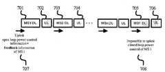
도 7은 사용자들이 상향링크의 한 채널을 함께 사용하는 경우의 개루프 전력 제어를 나타내는 도면이다. 즉, 단말기1(701)로의 전력제어 다음에 단말기1의 상향 링크(702)에서 수신한 전력을 기지국에서 다음 프레임의 다운링크(703)에서 단말기2에 대한 전력 제어의 정보로 사용할 수 없다. 이러한 점은 뒤에 나타나는 단말기 1(705)에 대해서도 마찬가지이다. 이와 같이 사용자들이 상향링크의 한 채널을 함께 사용하는 경우, 즉 한 사용자가 일정시간 이상 지속적(Continuously)으로 한 채널을 점유하지 않는 경우에는 기지국에서 어느 단말기(사용자)로부터의 전송 신호인지를 알 수 없기 때문에 폐루프 전력 제어가 가능하지 않으며, 개루프 전력제어만이 가능함을 나타낸다. 이미 언급한 바와 같이 차세대 무선 통신 시스템은 짧은 시간 내에 대량의 정보를 전달할 수 있어서, 대량 데이터의 지속적인 전송이 필요 없는 음성 통신 채널과 같은 경우, 한 채널을 여러 사용자가 시간적으로 분리하여 점유할 필요가 있으므로 이러한 경우에 해당한다.7 is a diagram illustrating open loop power control when users use one channel of uplink together. That is, the power received by the
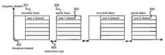
도 8은 TDD-OFDM/OFDMA 시스템에서 기지국과 단말기 사이의 상향링크(802)와 하향링크(801)의 구조를 나타내는 도면이다. 도 8에 나타난 바와 같이 TDD-OFDM/OFDMA 시스템에서는 도 2에 나타난 링크 구조와는 달리 각 채널들은 주파수 대역별로 완전하게 분리되어 있다. 또한, 상향 링크에서 한 채널은 한 시간 슬롯(Slot)내에서 한 명의 사용자(첫 번째 시간에는 805, 두 번째 시간에는 806)만이 사용하기 때문에 채널 사이의 간섭이 없다. 따라서 다른 채널을 고려한 전력 제어 정보를 필요로 하지 않는다.8 is a diagram illustrating the structure of an
따라서 이러한 채널간의 주파수가 완전히 분리되는 TDD-OFDM(Orthogonal Frequency Division Multiplexing) 또는 TDD-OFDMA(Orthogonal Frequency Division Multiple Access) 방식의 통신 시스템에서 대량 데이터를 지속적으로 송신 할 필요가 없는 경우(예를 들어 음성 통신의 경우) 한 채널을 여러 사용자가 시간적으로 분리하여 점유하는 경우, 즉 불연속적인 상향 링크 채널의 전력 제어 방법을 설명한다. 또한, 본 발명은 TDD-FDM(Time Division Duplex - Frequency Division Multiplexing) 또는 TDD-FDMA(Time Division Duplex - Frequency Division Multiple Access) 통신 시스템에도 적용가능하다Therefore, in a communication system based on Orthogonal Frequency Division Multiplexing (TDD-OFDM) or Orthogonal Frequency Division Multiple Access (TDD-OFDMA) system in which the frequencies between these channels are completely separated (for example, voice) In the case of communication), a method of controlling power of a discontinuous uplink channel when a channel is segregated and occupied by several users in time is described. The present invention is also applicable to a time division duplex (frequency division multiplexing) or time division duplex-frequency division multiple access (TDD-FDMA) communication system.
사용자(단말기)는 경로 감쇄(path loss), 채널 효과(channel effect) 및 외부 간섭(Interference)의 크기 등을 알면, 송신할 신호에 대한 기지국의 수신 전력을 추정할 수 있게 된다. TDD 시스템은 그 특성상 송신 및 수신 대역을 공유하므로, 상향 링크와 하향 링크가 동일한 경로 감쇄와 채널 효과를 겪는다고 볼 수 있고, 이렇게 가정하면 각 사용자들은 기지국으로부터 전송받은 하향링크의 전력량을 분석함으로써, 셀 외부 간섭 전력량을 제외한 상향 링크의 전력 제어 정보를 추정할 수 있다.If the user (terminal) knows the path loss, the channel effect and the magnitude of the external interference, the user can estimate the received power of the base station for the signal to be transmitted. Since the TDD system shares transmission and reception bands due to its characteristics, it can be seen that the uplink and the downlink have the same path attenuation and channel effects.Assuming this, each user analyzes the amount of downlink power transmitted from the base station. It is possible to estimate the power control information of the uplink excluding the amount of extracellular interference power.
기지국으로부터 단말기로의 하향링크 내의 프리앰블(Preamble) 또는 파일럿(Pilot)의 전력량 및 해당 대역의 평균 신호 전력량을 상향링크에 대한 경로 감쇄, 채널 효과 추정을 위한 요소로 활용할 수 있다. 특히, 이러한 요소들은 해당 채널 을 현재 사용 중이 아닌 단말기도 측정 및 활용이 가능한 전력량 정보가 되므로, 불연속적으로 해당 대역을 사용하는 단말기를 지원할 수 있다. 따라서 불연속적인 데이터 버스트(burst)들을 전송하는 통신 시스템의 특성에 잘 부합된다.The amount of power of the preamble or pilot in the downlink from the base station to the terminal and the average signal power of the corresponding band may be used as an element for estimating path attenuation for uplink and channel effect. In particular, since these elements become power information that can be measured and utilized by a terminal that is not currently using the channel, it can support a terminal that uses the corresponding band discontinuously. It is therefore well suited to the nature of a communication system transmitting discrete bursts of data.
다만, 여기에서 기지국이 수신하면서 겪는 외부 간섭 요인에 대해 각 단말기들은 알 수가 없다. 따라서 셀 외부 간섭의 전력량에 대해서는 기지국이 각 사용자에게 별도의 채널로 전송해야 한다. 그러나 이 정보 또한 셀 내의 해당 채널 대역을 사용하는 모든 사용자에게 공통적으로 적용되는 정보이므로, 브로드캐스트(broadcast) 채널을 통하여 주기적으로 이 정보를 전송하면 모든 단말기들이 공통적으로 이를 활용할 수 있다.However, here, each terminal cannot know about the external interference factor that the base station receives. Therefore, the base station should transmit a separate channel to each user for the amount of power outside the cell interference. However, since this information is also commonly applied to all users who use the corresponding channel band in the cell, all terminals can commonly use this information if the information is periodically transmitted through a broadcast channel.
기존의 시스템에서는 기지국의 셀 외부 간섭 전력량(IBTS)에 대해서는 상향링크 시작 시 개루프 전력 제어에서만 고려하였다. 그러나 본 발명에서는 기지국에서 주기적으로 또는 필요에 따라 불특정 시간에 이 정보를 전송하여 단말기에서 이 정보를 근거로 정확한 전력 제어를 지원한다.In the conventional system, only the open loop power control at the start of uplink is considered for the out-of-cell interference power amount (IBTS ) of the base station. However, in the present invention, the base station transmits this information periodically or at an unspecified time as necessary to support accurate power control based on this information in the terminal.
도 9는 본 발명에 따른 기지국-단말기 사이의 송신 및 수신 과정에 있어서 전력 제어 과정을 표시하였다. 최초에는 도 9에 나타난 바와 같이 경로 감쇄를 측정하기 위하여 하향링크의 프리앰블, 파일럿, 기타 해당 대역 내 데이터들의 평균 전력과 같은 요소들을 측정하여 호 생성시의 경로감쇄정보인 경로감쇄량(LBeacon)을 추정한다. 또한 별도로 기지국에서의 셀 외부 간섭 전력량(IBTS)을 기지국으로부터 수신하여 전력제어식에 사용한다.9 shows a power control process in the transmission and reception process between the base station and the terminal according to the present invention. Initially, as shown in FIG. 9, in order to measure path attenuation, elements such as downlink preamble, pilot, and average power of data in a corresponding band are measured to determine path loss amount (LBeacon ), which is path attenuation information at call generation. Estimate. In addition, the external cell interfering power (IBTS ) at the base station is received from the base station and used for power control.
이후부터는 마찬가지로 하향링크를 분석하여 주기적으로 또는 불특정시간에 대하여 수신-신호대간섭비(SINR)과 목표-신호대간섭비(SINR) 사이의 차이를 바탕으로 지속적으로 전송 전력 정보를 유지한다. 한편 또 다른 일정 주기 또는 불특정 시간에 대하여 기지국의 외부 셀 간섭 전력량(IBTS)을 기지국으로부터 단말기가 수신하면, 이에 따라서 기존의 외부 셀 간섭 전력량 정보를 갱신하고, 이에 따라 전력량을 제어하게 된다. 제어된 전력량은 아래의 <수학식 2>와 같다.From now on, the downlink is analyzed and the transmission power information is continuously maintained based on the difference between the reception-signal-to-interference ratio (SINR) and the target-signal-to-interference ratio (SINR) periodically or for an unspecified time. On the other hand, when the terminal receives the external cell interference power amount (IBTS ) of the base station from another base station for another predetermined period or unspecified time, the existing external cell interference power amount information is updated accordingly, thereby controlling the amount of power. The controlled power amount is shown in

여기에서


여기에서


여기서 전력제어 계산요소

여기서


이때,


또는,or,

여기서


위 <수학식 4>에서
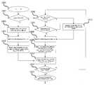
도 10은 본 발명에 따른 단말기에서의 전력 제어 과정에 대한 흐름도이다. 도 10에 나타난 바와 같이 최초 호(Call)가 연결되었을 때(1002)에는 이전 프레임의 전력 변화량에 대한 정보 즉, 이전 프레임의 전력제어요소(G(n-1))가 없으므로, 단말기는 브로드캐스트(공통) 채널을 통하여 기지국으로부터 외부 셀 간섭 전력량(IBTS)을 수신한다(1003). 다음에는 하향링크 채널을 수신하여(1004), 경로 감쇄 값을 계산한다(1005). 다음에는 상기 언급한 정보를 바탕으로 위 <수학식2>에 따라 전송 경로 감쇄를 계산한다(1010).10 is a flowchart illustrating a power control process in a terminal according to the present invention. As shown in FIG. 10, when the first call (Call) is connected (1002), since there is no information on the power change amount of the previous frame, that is, the power control elementG (n-1) of the previous frame, the terminal broadcasts. The external cell interference power amount IBTS is received from the base station through the (common) channel (1003). Next, the downlink channel is received (1004), and the path attenuation value is calculated (1005). Next, the transmission path attenuation is calculated according to
이후의 호가 연결되어 있는 상태에서는 앞서 설명한 바와 같이 외부 셀간섭 전력량 정보에 대한 일정한 수신 주기가 되었을 경우(1006) 또는 상향링크로 송신할 데이터가 있는 경우(1007)에는 브로드캐스트 채널을 통해 기지국의 외부 셀 간섭량 정보(IBTS)를 갱신한다(1013). 한편, 기지국으로부터 하향링크로 신호를 수신 하고(1008) <수학식 4>의
도 11은 본 발명에 따른 전력 제어 방법을 구현하는 단말기 구성을 나타내는 도면이다. 도 11에서 비트 형성기(1101), FEC(1102), 인터리버(1103), 변조기(1104), IFFT기(1105), RF단(1106), 송신 RF 증폭기(1107)등은 송신부를 구성한다. 또한, 수신 RF증폭기(1114), RF단(1113), FFT기(1112), 복조기(1111), 디인터리버(1110), FEC(1109), 수신정보블럭(1108)등은 수신부를 구성한다. 이 송신부와 수신부의 구성요소들은 일반적인 OFDM 및 OFDMA 시스템의 구성 요소들이다.11 is a diagram illustrating a terminal configuration for implementing a power control method according to the present invention. In FIG. 11, the bit former 1101, the
본 발명은 이와 같은 시스템에 하향링크 전력 분석부(Downlink Power Analyzer)(1116)을 두어 수신부, 구체적으로는 수신 RF증폭기(1114)와 FFT기(1112),로부터 수신신호를 전달받아 하향 프레임의 프리앰블, 파일럿 등을 이용하여 구한 현재의 경로 감쇄량인LBeacon과 기지국(BTS)에서의 외부 셀 간섭 전력량IBTS 를 알아낸다.According to the present invention, a
하향링크 전력 분석부는 계산한 값을 상향링크 전력 계산부(Uplink Power Calculator)(1115)로 전달한다. 상향링크 전력 계산부는 전달받은 값을 이용하여 상향링크 전송 전력량을 구한다. 위의 하향 링크 전력 분석부와 상향 링크 전력 계산부는 하나의 블록으로 구성할 수 있으며, 이 경우에 이를 상향 링크 전력 결정부 라 한다. 계산한 상향링크 전력 값은 상향링크 전력 제어부(1117)로 전달하며, 이 상향 링크 전력 제어부는 송신부, 구체적으로는 송신 RF 증폭기(1107),를 제어하여 상향 링크 전력을 제어한다. 즉, 단말기는 하향링크 전력을 분석하고, 브로드캐스트(broadcast) 채널을 통하여 수신되는 외부 셀 간섭 전력량(IBTS)을 사용하여 상향 링크 전력을 제어한다.The downlink power analyzer transfers the calculated value to the
이러한 본 발명은 TDD-OFDM(Time Division Duplex - Orthogonal Frequency Division Multiplexing), TDD-OFDMA(Time Division Duplex - Orthogonal Frequency Division Multiple Access) 통신 시스템뿐만 아니라 TDD-FDM(Frequency Division Multiplexing), TDD-FDMA(Frequency Division Multiple Access) 통신 시스템에도 적용가능하다.The present invention includes not only Time Division Duplex-Orthogonal Frequency Division Multiplexing (TDD-OFDM), Time Division Duplex-Orthogonal Frequency Division Multiple Access (TDD-OFDMA) communication system, but also Frequency Division Multiplexing (TDD-FDM) and TDD-FDMA (Frequency). Division Multiple Access) is also applicable to a communication system.
본 발명은 한 채널을 통한 대량 데이터의 지속적인 전송이 필요 없는 음성 통신(예를 들어 VoIP)과 같이 한 채널을 여러 사용자가 시간적으로 분리하여 점유하는 불연속적인 상향 링크 채널에 대하여, 별도의 귀환(feedback)값을 필요로 하지 않으면서 기존의 폐루프 전력제어방법보다 우수한 성능의 전력 제어 방법을 제공한다. 따라서 기존 시스템에서 지원하지 못했던, 불연속적인 상향링크 사용자를 지원할 수 있으며, 동시에 호(Call)가 연결되어 있는 동안에도 전력 증감 변화량에 따라 제어할 수 있다. 따라서 차세대 통신 시스템의 특성에 부합하면서, 전력 제어 알고리즘을 개선하고 전송 효율을 높일 수 있다.The present invention provides a separate feedback for a discontinuous uplink channel occupied by multiple users in time, such as voice communication (e.g. VoIP), which does not require continuous transmission of large amounts of data over one channel. It provides a power control method with better performance than the conventional closed loop power control method without requiring a value of. Therefore, it is possible to support discontinuous uplink users, which was not supported by the existing system, and at the same time, it can be controlled according to the change in power increase and decrease while the call is connected. Therefore, it is possible to improve power control algorithms and increase transmission efficiency while meeting the characteristics of next-generation communication systems.
Claims (20)
Translated fromKorean


Priority Applications (2)
| Application Number | Priority Date | Filing Date | Title |
|---|---|---|---|
| KR1020050118762AKR20070059666A (en) | 2005-12-07 | 2005-12-07 | Method and apparatus for controlling power in time division duplex communication system |
| US11/635,072US20070129094A1 (en) | 2005-12-07 | 2006-12-07 | Power control apparatus and method of time division duplex (TDD) telecommunication system |
Applications Claiming Priority (1)
| Application Number | Priority Date | Filing Date | Title |
|---|---|---|---|
| KR1020050118762AKR20070059666A (en) | 2005-12-07 | 2005-12-07 | Method and apparatus for controlling power in time division duplex communication system |
Publications (1)
| Publication Number | Publication Date |
|---|---|
| KR20070059666Atrue KR20070059666A (en) | 2007-06-12 |
Family
ID=38119472
Family Applications (1)
| Application Number | Title | Priority Date | Filing Date |
|---|---|---|---|
| KR1020050118762ACeasedKR20070059666A (en) | 2005-12-07 | 2005-12-07 | Method and apparatus for controlling power in time division duplex communication system |
Country Status (2)
| Country | Link |
|---|---|
| US (1) | US20070129094A1 (en) |
| KR (1) | KR20070059666A (en) |
Cited By (1)
| Publication number | Priority date | Publication date | Assignee | Title |
|---|---|---|---|---|
| WO2014137130A1 (en)* | 2013-03-07 | 2014-09-12 | 엘지전자 주식회사 | Method for mitigating interference when changing use of dynamic resource in wireless communication system, and device therefor |
Families Citing this family (16)
| Publication number | Priority date | Publication date | Assignee | Title |
|---|---|---|---|---|
| KR20060016042A (en)* | 2004-08-16 | 2006-02-21 | 삼성전자주식회사 | Apparatus and method for controlling uplink power in a mobile communication system using time division duplexing |
| US7917164B2 (en)* | 2007-01-09 | 2011-03-29 | Alcatel-Lucent Usa Inc. | Reverse link power control |
| WO2009075548A1 (en)* | 2007-12-12 | 2009-06-18 | Lg Electronics Inc. | A method for controlling uplink power control considering multiplexing rate/ratio |
| KR101572880B1 (en)* | 2007-12-12 | 2015-11-30 | 엘지전자 주식회사 | A method for controlling uplink power control considering multiplexing rate/ratio |
| US8238958B2 (en)* | 2008-04-11 | 2012-08-07 | Wi-Lan Inc. | Method, apparatus, and system for uplink modulation and coding scheme selection |
| JP2009260772A (en)* | 2008-04-18 | 2009-11-05 | Kyocera Corp | Mobile station device and method of controlling transmission power |
| WO2009133420A1 (en)* | 2008-04-29 | 2009-11-05 | Nokia Siemens Networks Oy | Method and apparatus for controlling transmit power of a user equipment |
| US8219136B2 (en)* | 2009-02-09 | 2012-07-10 | Intel Corporation | Techniques to determine transmitter power |
| CN101860948B (en)* | 2009-04-13 | 2014-07-30 | 华为技术有限公司 | Method, device and system for adjusting power consumption |
| CN101883415B (en)* | 2009-05-05 | 2013-06-05 | 电信科学技术研究院 | Configuration method of sending power of sounding reference signals (SRS), network side equipment and user equipment (UE) |
| US8340593B2 (en)* | 2009-11-10 | 2012-12-25 | Intel Corporation | Techniques to control uplink power |
| WO2011111988A2 (en)* | 2010-03-08 | 2011-09-15 | 엘지전자 주식회사 | Method and apparatus for controlling uplink transmission power |
| CN103582000A (en) | 2012-08-10 | 2014-02-12 | 北京三星通信技术研究有限公司 | Interference coordinating method |
| US10225809B2 (en) | 2014-04-04 | 2019-03-05 | British Telecommunications Public Limited Company | Power based frame timing synchronization for a time-division duplexing network |
| US20160309420A1 (en)* | 2015-04-15 | 2016-10-20 | Qualcomm Incorporated | Adaptation of transmission power and packet size in a wireless docking environment |
| IL300748A (en)* | 2023-02-17 | 2024-09-01 | Qualcomm Inc | Interband power correlation report for continuous user equipment uplink power control |
Citations (6)
| Publication number | Priority date | Publication date | Assignee | Title |
|---|---|---|---|---|
| KR20010015203A (en)* | 1999-07-08 | 2001-02-26 | 루센트 테크놀러지스 인크 | Method for controlling power for a communications system having multiple traffic channels per subscriber |
| KR20010108362A (en)* | 1999-03-22 | 2001-12-07 | 볼리스 도날드 엠. | Weighted open loop power control in a time division duplex communication system |
| KR20020061529A (en)* | 2001-01-15 | 2002-07-24 | 삼성전자 주식회사 | A power control method in narrow band time division duplexing code division multiple access communication system and apparatus thereof |
| US20030100269A1 (en)* | 2000-05-12 | 2003-05-29 | Otto-Aleksanteri Lehtinen | Power control in radio system |
| WO2004095765A2 (en)* | 2003-03-27 | 2004-11-04 | Interdigital Technology Corporation | Method and apparatus for estimating and controlling initial time slot gain in a wireless communication system |
| KR20050069848A (en)* | 2003-12-29 | 2005-07-05 | 삼성전자주식회사 | Apparatus for adaptive open-loop power control in mobile communication system using time division duplex and the method thereof |
Family Cites Families (6)
| Publication number | Priority date | Publication date | Assignee | Title |
|---|---|---|---|---|
| US5528593A (en)* | 1994-09-30 | 1996-06-18 | Qualcomm Incorporated | Method and apparatus for controlling power in a variable rate communication system |
| US6167244A (en)* | 1996-09-05 | 2000-12-26 | Mitsubishi Denki Kabushiki Kaisha | Gain control method and receiver |
| US6058107A (en)* | 1998-04-08 | 2000-05-02 | Motorola, Inc. | Method for updating forward power control in a communication system |
| US6587697B2 (en)* | 2001-05-14 | 2003-07-01 | Interdigital Technology Corporation | Common control channel uplink power control for adaptive modulation and coding techniques |
| GB2381417A (en)* | 2001-10-24 | 2003-04-30 | Ipwireless Inc | Transmission power control based on path loss |
| US7570968B2 (en)* | 2003-12-29 | 2009-08-04 | Samsung Electronics Co., Ltd | Method and apparatus for adaptive open-loop power control in mobile communication system using TDD |
- 2005
- 2005-12-07KRKR1020050118762Apatent/KR20070059666A/ennot_activeCeased
- 2006
- 2006-12-07USUS11/635,072patent/US20070129094A1/ennot_activeAbandoned
Patent Citations (6)
| Publication number | Priority date | Publication date | Assignee | Title |
|---|---|---|---|---|
| KR20010108362A (en)* | 1999-03-22 | 2001-12-07 | 볼리스 도날드 엠. | Weighted open loop power control in a time division duplex communication system |
| KR20010015203A (en)* | 1999-07-08 | 2001-02-26 | 루센트 테크놀러지스 인크 | Method for controlling power for a communications system having multiple traffic channels per subscriber |
| US20030100269A1 (en)* | 2000-05-12 | 2003-05-29 | Otto-Aleksanteri Lehtinen | Power control in radio system |
| KR20020061529A (en)* | 2001-01-15 | 2002-07-24 | 삼성전자 주식회사 | A power control method in narrow band time division duplexing code division multiple access communication system and apparatus thereof |
| WO2004095765A2 (en)* | 2003-03-27 | 2004-11-04 | Interdigital Technology Corporation | Method and apparatus for estimating and controlling initial time slot gain in a wireless communication system |
| KR20050069848A (en)* | 2003-12-29 | 2005-07-05 | 삼성전자주식회사 | Apparatus for adaptive open-loop power control in mobile communication system using time division duplex and the method thereof |
Cited By (2)
| Publication number | Priority date | Publication date | Assignee | Title |
|---|---|---|---|---|
| WO2014137130A1 (en)* | 2013-03-07 | 2014-09-12 | 엘지전자 주식회사 | Method for mitigating interference when changing use of dynamic resource in wireless communication system, and device therefor |
| US9554391B2 (en) | 2013-03-07 | 2017-01-24 | Lg Electronics Inc. | Method for mitigating interference when changing use of dynamic resource in wireless communication system, and device therefor |
Also Published As
| Publication number | Publication date |
|---|---|
| US20070129094A1 (en) | 2007-06-07 |
Similar Documents
| Publication | Publication Date | Title |
|---|---|---|
| KR102246888B1 (en) | A method and apparatus for transmission power control of soucindg reference signals | |
| US20070129094A1 (en) | Power control apparatus and method of time division duplex (TDD) telecommunication system | |
| US10285137B2 (en) | Wireless communication base station device, wireless communication method and integrated circuit for controlling transmission power of sounding reference signal (SRS) | |
| KR100725773B1 (en) | Apparatus and method for adaptively changing uplink power control scheme according to terminal state in time division duplex mobile communication system | |
| RU2749350C2 (en) | Method for measuring interference and related apparatus | |
| KR100964577B1 (en) | Power control method and system in communication system | |
| KR101424264B1 (en) | Method for uplink power control in the wireless communication system | |
| US6597723B1 (en) | Weighted open loop power control in a time division duplex communication system | |
| KR100869922B1 (en) | Device and method for controlling uplink power in broadband wireless communication system | |
| KR101556515B1 (en) | Uplink power control apparatus and method in a wireless communication system | |
| KR20010013848A (en) | Radio communication device and method of controlling transmission rate | |
| CN104471994A (en) | Controlling the transmission power of the uplink sounding reference signal | |
| EP1163738A1 (en) | Weighted open loop power control in a time division duplex communication system | |
| WO2010085185A1 (en) | Method of estimating path loss for a channel | |
| KR100957409B1 (en) | Power control system and method in communication system | |
| WO2010068160A1 (en) | Adaptive power control in tdd mode | |
| US9313735B2 (en) | Method and apparatus for efficiently controlling uplink control signal of user equipment in wireless communication system | |
| Saha et al. | Link adaptation using dynamically allocated thresholds and power control | |
| KR20050026089A (en) | Equalizing signal-to-interference ratios of different physical channels supporting a coded composite transport channel | |
| KR20060015192A (en) | Closed loop power control method and apparatus for controlling individual transmit power of subcarriers in orthogonal frequency division multiplexing / orthogonal frequency division multiple access communication system | |
| KR100519666B1 (en) | Power Allocation Apparatus and Method for Packet Data Services in Mobile Communications Systems | |
| KR20120006259A (en) | Apparatus and method for reporting uplink transmit power status in mobile communication system | |
| HK1109252B (en) | Weighted open loop power control in a time division duplex communication system | |
| HK1106346B (en) | Weighted open loop power control in a time division duplex communication system |
Legal Events
| Date | Code | Title | Description |
|---|---|---|---|
| PA0109 | Patent application | Patent event code:PA01091R01D Comment text:Patent Application Patent event date:20051207 | |
| A201 | Request for examination | ||
| PA0201 | Request for examination | Patent event code:PA02012R01D Patent event date:20070125 Comment text:Request for Examination of Application Patent event code:PA02011R01I Patent event date:20051207 Comment text:Patent Application | |
| PG1501 | Laying open of application | ||
| E902 | Notification of reason for refusal | ||
| PE0902 | Notice of grounds for rejection | Comment text:Notification of reason for refusal Patent event date:20080228 Patent event code:PE09021S01D | |
| E601 | Decision to refuse application | ||
| PE0601 | Decision on rejection of patent | Patent event date:20080530 Comment text:Decision to Refuse Application Patent event code:PE06012S01D Patent event date:20080228 Comment text:Notification of reason for refusal Patent event code:PE06011S01I |