KR20070045093A - Hip Joint Expander - Google Patents
Hip Joint ExpanderDownload PDFInfo
- Publication number
- KR20070045093A KR20070045093AKR1020060100397AKR20060100397AKR20070045093AKR 20070045093 AKR20070045093 AKR 20070045093AKR 1020060100397 AKR1020060100397 AKR 1020060100397AKR 20060100397 AKR20060100397 AKR 20060100397AKR 20070045093 AKR20070045093 AKR 20070045093A
- Authority
- KR
- South Korea
- Prior art keywords
- shaft
- handle
- slide
- spring
- ball
- Prior art date
- Legal status (The legal status is an assumption and is not a legal conclusion. Google has not performed a legal analysis and makes no representation as to the accuracy of the status listed.)
- Ceased
Links
- 210000004394hip jointAnatomy0.000titleabstractdescription5
- 238000000034methodMethods0.000claimsdescription16
- 230000008878couplingEffects0.000claimsdescription5
- 238000010168coupling processMethods0.000claimsdescription5
- 238000005859coupling reactionMethods0.000claimsdescription5
- 229920003002synthetic resinPolymers0.000claimsdescription5
- 239000000057synthetic resinSubstances0.000claimsdescription5
- 210000005036nerveAnatomy0.000description5
- 230000009471actionEffects0.000description4
- 210000001519tissueAnatomy0.000description4
- 208000031481Pathologic ConstrictionDiseases0.000description3
- 210000001503jointAnatomy0.000description3
- 230000036262stenosisEffects0.000description3
- 208000037804stenosisDiseases0.000description3
- 210000002517zygapophyseal jointAnatomy0.000description3
- 210000000988bone and boneAnatomy0.000description2
- 239000003086colorantSubstances0.000description2
- 238000002347injectionMethods0.000description2
- 239000007924injectionSubstances0.000description2
- 210000005070sphincterAnatomy0.000description2
- 229910000831SteelInorganic materials0.000description1
- 238000010521absorption reactionMethods0.000description1
- 230000015572biosynthetic processEffects0.000description1
- 210000003169central nervous systemAnatomy0.000description1
- 238000004140cleaningMethods0.000description1
- 230000006837decompressionEffects0.000description1
- 238000005538encapsulationMethods0.000description1
- 238000001125extrusionMethods0.000description1
- 238000003780insertionMethods0.000description1
- 230000037431insertionEffects0.000description1
- 230000007246mechanismEffects0.000description1
- 230000001537neural effectEffects0.000description1
- 230000008569processEffects0.000description1
- 239000000523sampleSubstances0.000description1
- 231100000241scarToxicity0.000description1
- 210000000278spinal cordAnatomy0.000description1
- 239000010959steelSubstances0.000description1
- 230000001954sterilising effectEffects0.000description1
- 238000004659sterilization and disinfectionMethods0.000description1
- 239000004753textileSubstances0.000description1
Images


Classifications
- A—HUMAN NECESSITIES
- A61—MEDICAL OR VETERINARY SCIENCE; HYGIENE
- A61B—DIAGNOSIS; SURGERY; IDENTIFICATION
- A61B17/00—Surgical instruments, devices or methods
- A61B17/16—Instruments for performing osteoclasis; Drills or chisels for bones; Trepans
- A61B17/1637—Hollow drills or saws producing a curved cut, e.g. cylindrical
- A—HUMAN NECESSITIES
- A61—MEDICAL OR VETERINARY SCIENCE; HYGIENE
- A61B—DIAGNOSIS; SURGERY; IDENTIFICATION
- A61B17/00—Surgical instruments, devices or methods
- A61B17/16—Instruments for performing osteoclasis; Drills or chisels for bones; Trepans
- A61B17/1662—Instruments for performing osteoclasis; Drills or chisels for bones; Trepans for particular parts of the body
- A61B17/1671—Instruments for performing osteoclasis; Drills or chisels for bones; Trepans for particular parts of the body for the spine
- A—HUMAN NECESSITIES
- A61—MEDICAL OR VETERINARY SCIENCE; HYGIENE
- A61B—DIAGNOSIS; SURGERY; IDENTIFICATION
- A61B17/00—Surgical instruments, devices or methods
- A61B2017/0046—Surgical instruments, devices or methods with a releasable handle; with handle and operating part separable
- A61B2017/00464—Surgical instruments, devices or methods with a releasable handle; with handle and operating part separable for use with different instruments
Landscapes
- Health & Medical Sciences (AREA)
- Surgery (AREA)
- Life Sciences & Earth Sciences (AREA)
- Biomedical Technology (AREA)
- Medical Informatics (AREA)
- Orthopedic Medicine & Surgery (AREA)
- Oral & Maxillofacial Surgery (AREA)
- Engineering & Computer Science (AREA)
- Dentistry (AREA)
- Heart & Thoracic Surgery (AREA)
- Nuclear Medicine, Radiotherapy & Molecular Imaging (AREA)
- Molecular Biology (AREA)
- Animal Behavior & Ethology (AREA)
- General Health & Medical Sciences (AREA)
- Public Health (AREA)
- Veterinary Medicine (AREA)
- Surgical Instruments (AREA)
- Prostheses (AREA)
Abstract
Translated fromKoreanDescription
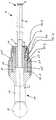
Translated fromKorean도 1은 본 발명의 한 실시예에 따른 후관절 구멍 확장기에 대한 부분 종단면도이다.1 is a partial longitudinal cross-sectional view of a hip joint expander in accordance with one embodiment of the present invention.
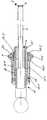
도 2은 본 발명의 다른 실시예에 따른 후관절 구멍 확장기에 대한 부분 종단면도이다.2 is a partial longitudinal cross-sectional view of a posterior joint hole expander in accordance with another embodiment of the present invention.
도 3은 본 발명의 후관절 구멍 확장기의 핸들의 삽입구에 대한 정면도이다.Figure 3 is a front view of the insertion hole of the handle of the posterior joint hole expander of the present invention.
도 4는 인간 척주(vertebral column)의 두 개의 인접한 요추에 대한 배면도이다.4 is a rear view of two adjacent lumbar vertebrae of the human vertebral column.
도 5는 도 4의 두 개의 척추 사이의 추간판의 부분 단면도이다.5 is a partial cross-sectional view of the intervertebral disc between the two vertebrae of FIG. 4.
<도면의 주요 부분에 대한 간단한 설명><Brief description of the main parts of the drawing>
1 후관절 구멍 확장기, 2 샤프트1 hip joint expander, 2 shafts
3 원형 단부, 4 톱니부3 circular ends, 4 tooth
5 몸측 단부, 6 고정부5 body ends, 6 fixings
7 함몰부, 11 핸들7 depressions, 11 handles
12 T자형 핸들부, 12.1 환형부12 T-shaped handle part, 12.1 round shape
13 세로봉, 14 가로봉13 vertical rods, 14 horizontal rods
15 슬리브, 15.1 링 플랜지15 sleeves, 15.1 ring flange
15' 슬리브, 15.1' 어깨부15 'sleeve, 15.1' shoulder
15.2' 어깨부, 16 연결부15.2 'shoulder, 16 connections
17 슬라이드, 17.1 환형 어깨부17 slides, 17.1 annular shoulder
17.2 측벽, 17.3 홈17.2 sidewalls, 17.3 grooves
17.4 그립 홈, 17.5 그립부17.4 grip groove, 17.5 grip
17' 슬라이드, 17.1' 환형부17 'slide, 17.1' annulus
17.2' 어깨부, 17.3' 구역17.2 'shoulder, 17.3' section
17.4' 확장된 구역, 17.5' 그립부17.4 'extended area, 17.5' grip
18 코일 스프링, 19 홈18 coil springs, 19 grooves
20 볼, 22 척주관20 ball, 22 spinal column
23, 24, 25 신경 구조, 30 추간판23, 24, 25 nerve structures, 30 intervertebral discs
31 섬유테, 33 협착부31 textile frames, 33 stenosis
34 압출부, 40 가시 돌기34 extrusions, 40 spines
42 횡돌기, 43 돌기42 turning, 43 turning
44 돌기, 46 후관절44 protuberances, 46 hip joints
54 트로카(trocar), L4, L5 요추54 trocar, L4, L5 lumbar vertebrae
본 발명은 실질적으로 원통형인 샤프트, 샤프트의 원형 단부에 톱니부 및 몸 측 단부에 핸들이 구비된 후관절 구멍 확장기에 관한 것이다.The present invention relates to a substantially cylindrical shaft, a posterior joint dilator having a toothed portion at the circular end of the shaft and a handle at the body side end.
후관절 구멍 확장기는 독일 특허 DE 699 17 683 T2에 공개되어 있다. 이 알려진 구멍 확장기는 중공 원통형 샤프트, 그 후방 몸측 단부에 핸들 및 그 정면측 단부에 톱니부를 포함한다.The facet joint dilator is disclosed in German patent DE 699 17 683 T2. This known hole expander comprises a hollow cylindrical shaft, a handle at its rear body end and a tooth at its front side end.
중추신경계의 괄약된 신경근에 대해 후측방 접근로를 형성하기 위해, 상기 구멍 확장기는 척주 척수의 측면 돌기 부위에서 척추 구성요소를 절삭하는데 사용된다. 이 접근로를 통해 수핵 조직 및 다른 조직 유형(피막 조직, 반흔 조직, 고리 조직)이 제거되는데, 그 이유는 이러한 조직들이 신경근을 압박하기 때문이다. 이러한 척추의 돌기는 인접한 척추의 인접한 돌기와 함께 소위 후관절(facet joint)을 형성한다.To form a posterior access to the sphincter nerve roots of the central nervous system, the orifice dilator is used to cut vertebral components at the lateral spine of the spinal cord. This approach removes nucleus pulposus and other tissue types (encapsulation, scar tissue, ring tissue) because these tissues compress the nerve roots. These spinal processes form so-called facet joints with adjacent spines of adjacent vertebrae.
괄약된 신경근의 감압을 위해 후관절 구멍 확장기가 사용되는 미세침윤 수술 방법이 매우 성공적이다. 하지만 일반적인 청소 및 멸균 작업 시 톱니부의 구역에 골조직이 잔존할 수 있으며, 이러한 골조직은 상당히 신중한 방법을 통해 조심스럽게 제거되어야 한다. 또한 서로 다른 두께의 구멍 확장기가 사용되므로, 공통의 조작 핸들과 함께 사용할 수 있는 다양한 구멍 확장기가 요구된다.The microinvasive surgical method in which the posterior joint dilator is used for decompression of the sphincter nerve root is very successful. However, during normal cleaning and sterilization work, bone tissue may remain in the area of the tooth, and this bone tissue must be carefully removed in a very careful manner. In addition, since hole expanders of different thicknesses are used, various hole expanders that can be used with a common operation handle are required.
따라서 본 발명의 목적은 후관절 구멍 확장기를 개선하는 것이다.It is therefore an object of the present invention to improve the posterior joint dilator.
전술한 목적을 달성하기 위해, 본 발명에서는 샤프트와 핸들을 분리할 수 있는, 특히 샤프트와 핸들을 손상 없이 분리할 수 있는 것을 특징으로 하는 후관절 구멍 확장기가 제공된다.In order to achieve the above object, the present invention provides a posterior joint hole expander, which is capable of separating the shaft and the handle, in particular the shaft and the handle can be removed without damage.
하나의 구체적인 예로는, 연동하는 결합 장치를 구비한 핸들 및 샤프트가 제공되며, 샤프트는 그 몸측 단부에서 측면 함몰부를 포함하며, 핸들에 지지되는 볼이 이 함몰부에 맞물리고, 이 볼은 다시 구멍 확장기 샤프트의 홈에 삽입될 수 있도록 결합 장치가 형성된다. 볼은 핸들에서 잠길(lock) 수 있고, 따라서 구멍 확장기 샤프트가 핸들에서 안정적으로 고정된다. 핸들으로부터 샤프트를 해제하기 위한 해제 위치와 샤프트가 핸들에서 안정적으로 고정되는 잠김 위치 사이에서 슬라이드가 이동할 수 있어, 이러한 잠김이 가능하다.In one specific example, a handle and a shaft having an interlocking engagement device are provided, the shaft including a side depression at its body end, and a ball supported by the handle engages the depression, which in turn is a hole. The coupling device is formed to be inserted into the groove of the dilator shaft. The ball can be locked at the handle, so that the hole expander shaft is reliably fixed at the handle. This locking is possible because the slide can move between a release position for releasing the shaft from the handle and a locked position in which the shaft is stably fixed at the handle.
다른 구체적인 예로는, 슬라이드가 스프링에 의해 부하를 받게 되는데, 더욱 상세하게는 슬라이드가 잠김 위치에서 스프링에 의해 고정된다.In another specific example, the slide is loaded by a spring, more particularly the slide is fixed by the spring in the locked position.
또 다른 구체적인 예로는, 슬라이드가 확장된 내부 구역을 포함한다. 이로써 슬라이드가 볼에 도달하면 볼이 이동할 수 있는 구역이 슬라이드 내에 형성되며, 따라서 이로 인해 구멍 확장기 샤프트를 위한 해제 위치가 형성되고 또한 슬라이드와 볼의 이 위치에서 구멍 확장기 샤프트를 핸들로부터 제거할 수 있다.Another specific example includes an inner zone in which the slide is extended. This creates an area in the slide where the ball can move when the slide reaches the ball, thereby creating a release position for the hole expander shaft and also removing the hole expander shaft from the handle at this position of the slide and the ball. .
또한, 추가적으로 슬라이드가 그 잠김 위치에서 손의 힘에 의해 스프링 힘에 대항하여 그 해제 위치로 이동할 수 있으며, 슬라이드가 몸측(proximal) 방향에서 스프링의 작용에 대항하여 그 해제 위치로 이동되거나 또는 슬라이드가 스프링의 작용에 대항하여 원형(distal) 방향으로 그 해제 위치로 이동되는 것은 시술자의 다양한 선호 의지에 따라 결정할 수 있다.Additionally, the slide may be moved to its release position against the spring force by hand force in its locked position, and the slide may be moved to its release position against the action of the spring in the proximal direction or the slide may be The movement to the release position in the radial direction against the action of the spring can be determined according to the operator's various preferences.
또 다른 구체적인 예로는, 샤프트와 핸들이 비틀리지 않게 서로 결합되며, 특히 샤프트의 결합부가 외측 다각형, 특히 삼각형으로서 형성되며 그립의 수용부는 내측 다각형, 바람직하게는 내측 삼각형으로서 형성된다.In another specific example, the shaft and the handle are coupled to each other without twisting, in particular the engaging portion of the shaft is formed as an outer polygon, in particular a triangle and the receiving portion of the grip is formed as an inner polygon, preferably an inner triangle.
또 다른 구체적인 예로는, 샤프트의 결합부가 합성수지로 이루어지며, 결합부가 견고하게 비탈착식으로 (적어도 손상 없이는 분리할 수 없게) 구멍 확장기 샤프트와 예를 들어 그 둘레에 사출됨으로써 결합된다.이렇게 함으로써 예를 들어 합성수지부의 서로 다른 색상을 통해, 즉 서로 다른 파장 영역에서의 반사 흡수력을 갖는 색상의 형성을 통해 샤프트 두께를 다양하게 코딩할 수 있다. 또한 시술 시 신경을 보호하기 위해 톱니부를 초과하여 돌출되는 측면 보호 립(protection lip)이 구멍 확장기 샤프트에 포함되는 경우에는, 합성수지 부분에 예를 들어 융기부 형태의 표시 마크가 제공될 수 있으며, 이 표시 마크는 원위 구멍 확장기의 립과 정렬된다.In another specific example, the coupling portion of the shaft is made of synthetic resin, and the coupling portion is rigidly non-removable (at least inseparably detachable) and coupled to the hole expander shaft, for example by injection around it. By doing so, the shaft thickness can be variously coded, for example, through the different colors of the synthetic resin, ie the formation of colors with reflective absorption in different wavelength ranges. In addition, when the dilator shaft includes a lateral protection lip protruding beyond the teeth to protect the nerve during the procedure, the synthetic resin portion may be provided with a mark for example in the form of a ridge. The mark is aligned with the lip of the distal hole expander.
본 발명의 추가 이점 및 특징은 본 발명에 따른 후관절 구멍 확장기의 바람직한 두 개의 실시예를 기술하는 하기 설명 및 청구항에 보여질 수 있다.Further advantages and features of the present invention can be seen in the following description and claims which describe two preferred embodiments of the facet joint dilator according to the present invention.
본 발명의 한 실시예에 따른 후관절 구멍 확장기(1)는 강철 재질의 실질적으로 원통형인 샤프트(2)를 포함하며, 상기 샤프트(2)의 원형 단부(3)에는 톱니부(4)가 형성되어 있다. 샤프트(2)는 몸측 단부(5)에서 그에 사출 성형된 다각형, 본 실시예에서는 삼각형인 합성수지 슬리브 형태의 고정부(6)를 포함하며, 그 측벽에는 함몰부(7)가 형성되어 있다.The posterior joint hole expander 1 according to an embodiment of the present invention includes a substantially
샤프트(2)는 손상 없이 분리할 수 있도록 핸들(11)과 결합될 수 있다.The
핸들(11)은 세로봉(13)을 구비한 T자 형태의 핸들부(12) 및 그 원형 단부에서 가로봉(14)을 포함한다. 슬리브(15)가 핸들부(12), 더욱 정확하게는 세로봉(13)의 몸측 단부와 고정적으로 결합하며, 그 단부에는 다시 연결부(16)가 고정된다. 슬라이드(17)는 슬리브를 따라 스프링(18)의 작용에 대항하여 축방향으로 슬라이딩 이동이 가능하며, 이 스프링(18)은 슬리브(15)와 슬라이드(17) 사이의 홈(19)에 배치되고, 그 지지부는 일단이 도 1에 도시한 실시예에서 근위측으로 핸들부(12)의 정면 환형부(12.1)에 있고 타단이 슬라이드(17)의 환형 어깨부(17.1)에 있으므로, 스프링(18)이 이 원형 방향으로 부하되거나 또는 눌린다.The
슬리브(15)의 홈에는 홈을 한정하는 링 플랜지(15.1)에 의해 방사상의 내측으로 고정되는 볼(20)이 존재하므로, 볼(20)이 슬리브(15)에서부터 분리되지 않는다. 슬라이드(17)는 슬리브(15)에서 활주하는 구역(17.2)을 포함하는데, 도 1에 도시한 바와 같이 이 활주 구역을 통해 슬리브(15)가 부분(6)의 홈(7)에 삽입된다. 홈(17.3)이 슬리브(15)로부터 떨어진 측에 형성되는데, 이 홈(17.3)은 측벽(17.2)보다 더 큰 방사상 치수를 가지므로 구역(17.3)이 볼(20)의 축방향 높이에 도달하면 볼(20)이 해제되어 샤프트(2)가 핸들(11)에서부터 분리될 수 있다.In the groove of the
슬라이드(17)의 핸들(11) 횡단면(14)에 대하여 떨어진 측에는 그립 골(17.4)이 존재한다. 슬라이드(4)는 그립 골(17.4) 잡음 및 슬라이드(4)의 당김을 통해 스프링(18)에 대항하여 횡단면(14)으로부터 이동될 수 있고, 그로 인해 확장된 슬라이드의 홈(17.3)이 볼(20)의 축방향 높이에 도달하며 볼(20)이 해제되어 이러한 방식으로 구멍 확장기(2)가 분리 또는 삽입된다. 슬라이드(17)가 다시 놓여지면, 그 구역(17.2)이 스프링(18)의 작용에 의해 볼(20) 위로 이동하며, 이로써 볼(20)이 홈(7)에 눌리게 되고, 이러한 방식으로 볼(20)이 축방향 위치에서 구멍 확장기(2)를 잠근다.On the side away from the
핸들(11)의 홈 및 결합부(6)를 다각형으로 형성함으로써 마찬가지로 구멍 확장기가 핸들(11)내에서 회전되지 않게 고정된다.By forming the groove and the engaging
도 2는 본 발명에 따른 구멍 확장기(1)의 다른 실시예를 나타낸다. 동일한 부분은 동일한 부호로 표시되어 있다. 동일한 부분에 대한 설명은 전술한 실시예를 참조한다. 아래에서는 단지 차이점만 상세하게 설명된다.2 shows another embodiment of a hole expander 1 according to the invention. Identical parts are denoted by the same reference numerals. Description of the same parts refers to the above-described embodiment. Only the differences are explained in detail below.
도 2에 따른 실시예에서도 핸들(11)에 슬리브(15')가 제공되며 축방향에서 그를 따라 이동할 수 있는 슬라이드(17')에 의해 둘러싸인다. 슬리브(15')의 후단 몸측 단부에는 어깨부(15.1)가 형성되며, 마찬가지로 근위측 슬라이드(17')에 형성된 내측으로 돌출된 그 환형 층단(17.1') 사이에 다시 코일 스프링(18)이 배치된다. 이 스프링은 슬라이드(17')를 후방 또는 몸측 단부 방향으로 이동시킨다. 슬라이드는 슬라이드의 슬리브(15', 17.2')에 대응하는 어깨부(15.2')에 접한다.In the embodiment according to FIG. 2, the
또한 전술한 방식에 따라 슬리브(15')의 홈에서 볼(20)이 지지된다. 슬라이드(17')는 구역(17.3)을 포함하는데, 그 내경은 이 구역에서 슬리브(15)의 외경에 정렬된다. 구역(17.3')의 근위측에는 슬라이드의 확장된 구역(17.4')이 제공된다.The
슬라이드(17.1')는 스프링(18)을 통해 도 2에 도시한 위치로 압박되며, 이 위치에서 슬라이드(17')의 구역(17.3')이 볼(20)의 축방향 높이에 존재하며 볼이 결합부(6)의 홈(7)에 압입되고 샤프트(2)가 핸들(11)에서 고정된다.The slide 17.1 'is pushed through the
또한 슬라이드에는 그립부(17.5')가 형성되어 있는데, 이 그립부를 통해 슬라이드가 원형 단부 방향으로 이동될 수 있다.The slide is also provided with a grip 17.5 ', through which the slide can be moved in the direction of the circular end.
시술자가 그립부(17.5)를 잡고 슬라이드(17')를 원형 방향으로 밀면, 슬라이드(17')의 확장 구역(17.4')이 볼(20)의 축방향 높이에 도달하고, 이로써 볼이 방사상 방향에서 외측으로 이동할 수 있고, 홈(7)에서부터 이탈되며 따라서 샤프트(2)가 핸들(7)에서 제거될 수 있거나 또는 슬라이드의 이 위치에서 샤프트(2)가 핸들(11)에 삽입될 수 있다.When the operator grasps the grip portion 17.5 and pushes the slide 17 'in the circular direction, the expansion section 17.4' of the slide 17 'reaches the axial height of the
본 발명에 따른 구멍 확장기는 하기 도 4 및 도 5를 통해 설명되는 방식에 따라 사용된다. 도 4은 예시로서 제4 및 제5 요추(L4, L5), 및 척주관으로의 수핵 조직의 압출부(34)를 갖는 척주의 중앙축 우측에 인접한 섬유테(annulus fibrosus)(31)에서 협착부(33)를 포함하는 그 사이의 추간판(30)을 나타낸다(도 5참조).The hole expander according to the invention is used in the manner described through FIGS. 4 and 5 below. 4 shows the constriction in the
척주관(Vertebral Canal)(22) 내부에 있는 신경 구조(23, 24, 25)가 개략적으로 도시되어 있다. 각 척추(L4, L5)는 가시 돌기(40) 및 좌우측의 횡돌기(42), 관절을 형성하는 좌우측 아래의 돌기(43) 및 관절을 형성하는 좌우측 위의 돌기(44)를 포함하며, 후관절(46)로 불리는 위와 아래의 요추(L4, L5) 사이의 좌우측 관절이 위 척추(L4)의 아래 돌기(43) 및 아래 척추(L5)의 위 돌기(44)를 통해 각각 형성된다.The
본 발명에 따른 구멍 확장기가 사용되는 작업은 다음과 같은 방식으로 진행된다:The operation in which the hole expander according to the invention is used proceeds in the following way:
우선 외경이 대략 1.25 mm인 중공 니들 또는 탐침을 협착부에 인접한 위치로 삽입한다. 그 후에 그 원형 단부가 중공 니들의 단부에서 약간 돌출될 때까지, 안내 와이어를 중공 니들의 관내강을 통해 삽입한다. 그 다음 중공 니들을 떼어 내고, 반면 안내 와이어는 그 위치에 남게된다. 그 후 트로카의 무딘 단부가 후관절(46)에 도달 할 때까지, 트로카 튜브를 안내 와이어로 삽입한다. 이 위치에서 트로카를 잡은 상태에서 대략 내경이 4.5 mm인 더 작은 직경의 본 발명에 따른 구멍 확장기를 구멍 확장기의 원형 단부가 후관절(46)의 표면에 접할 때까지 트로카(54)로 삽입한다. 이제 시술자는 구멍 확장기의 그에 인접한 (근위) 단부에서 그에 존재하는 핸들을 예를 들어 손으로 회전시키면, 척추(L4)의 돌기(43)에서 채널이 형성된다. 겸자 기구 뿐 아니라 내시경도 통과할 정도의 충분한 내경의 삽입관을 수용할 수 있도록, 채널이 충분한 직경에 도달할 때까지, 더 큰 직경의 트로카 튜브 및 구멍 확장기로 이 단계는 반복한다. 이어서 필요 시 내시경으로 관찰하면서 겸자 기구를 이용해 협착부를 제거한다.First, a hollow needle or probe with an outer diameter of approximately 1.25 mm is inserted into a position adjacent to the stenosis. The guide wire is then inserted through the lumen of the hollow needle until its circular end slightly protrudes from the end of the hollow needle. The hollow needle is then removed, while the guide wire remains in that position. The trocar tube is then inserted into the guide wire until the blunt end of the trocar reaches the posterior joint 46. With the trocar in this position, insert a smaller diameter hole expander according to the invention into the trocar 54 until the circular end of the hole expander abuts the surface of the posterior joint 46. . The operator now rotates the handle present therefor at the (proximal) end of the hole dilator, for example by hand, whereby a channel is formed in the protrusion 43 of the spine L4. This step is repeated with a larger diameter trocar tube and hole expander until the channel reaches a sufficient diameter to accommodate both the forceps mechanism as well as the endoscope insert tube sufficient to pass through the endoscope. The stenosis is then removed using a forceps instrument while observing with an endoscope if necessary.
본 발명에 따른 후관절 구멍 확장기는 샤프트와 핸들이 분리될 수 있다. 특히 본 발명에 따른 후관절 구멍 확장기는 특히 샤프트와 핸들을 손상 없이 분리할 수 있다.The posterior joint hole expander according to the present invention may be separated from the shaft and the handle. In particular, the posterior joint hole expander according to the invention can, in particular, separate the shaft and the handle without damage.
Claims (14)
Translated fromKoreanApplications Claiming Priority (2)
| Application Number | Priority Date | Filing Date | Title |
|---|---|---|---|
| DE202005016761UDE202005016761U1 (en) | 2005-10-26 | 2005-10-26 | Surgical milling cutter in particular for removal of tissue from facet joint at spine, comprises handle to be attached with quick joining mechanism |
| DE202005016761.4 | 2005-10-26 |
Publications (1)
| Publication Number | Publication Date |
|---|---|
| KR20070045093Atrue KR20070045093A (en) | 2007-05-02 |
Family
ID=37545403
Family Applications (1)
| Application Number | Title | Priority Date | Filing Date |
|---|---|---|---|
| KR1020060100397ACeasedKR20070045093A (en) | 2005-10-26 | 2006-10-16 | Hip Joint Expander |
Country Status (5)
| Country | Link |
|---|---|
| US (1) | US20070123891A1 (en) |
| EP (1) | EP1779792A1 (en) |
| JP (1) | JP2007117720A (en) |
| KR (1) | KR20070045093A (en) |
| DE (1) | DE202005016761U1 (en) |
Families Citing this family (50)
| Publication number | Priority date | Publication date | Assignee | Title |
|---|---|---|---|---|
| US6793678B2 (en) | 2002-06-27 | 2004-09-21 | Depuy Acromed, Inc. | Prosthetic intervertebral motion disc having dampening |
| DE102004028429B3 (en)* | 2004-06-03 | 2005-11-03 | Karl Storz Gmbh & Co. Kg | Device for punching out tissue areas on bones |
| US8016830B2 (en)* | 2006-01-19 | 2011-09-13 | Warsaw Orthopedic, Inc. | Devices and methods for grasping an elongated medical element |
| ES2279733B1 (en) | 2006-11-27 | 2008-08-16 | Rudolf Morgenstern Lopez | DEVICE FOR ELIMINATION OF FABRIC IN ENDOSCOPIC OPERATIONS. |
| WO2008070863A2 (en) | 2006-12-07 | 2008-06-12 | Interventional Spine, Inc. | Intervertebral implant |
| DE102007002089A1 (en)* | 2007-01-09 | 2008-07-10 | Reinhard Feinmechanik Gmbh | Tool for drilling holes in bone or removing cylindrical cores from bones of the human body |
| US8900307B2 (en) | 2007-06-26 | 2014-12-02 | DePuy Synthes Products, LLC | Highly lordosed fusion cage |
| US8398642B2 (en) | 2007-09-20 | 2013-03-19 | Symmetry Medical, Inc. | Dual reamer driver |
| EP2237748B1 (en) | 2008-01-17 | 2012-09-05 | Synthes GmbH | An expandable intervertebral implant |
| CA2717610A1 (en)* | 2008-03-06 | 2009-09-11 | Synthes Usa, Llc | Facet interference screw |
| US8936641B2 (en) | 2008-04-05 | 2015-01-20 | DePuy Synthes Products, LLC | Expandable intervertebral implant |
| US9526620B2 (en) | 2009-03-30 | 2016-12-27 | DePuy Synthes Products, Inc. | Zero profile spinal fusion cage |
| KR101680132B1 (en) | 2009-10-01 | 2016-11-28 | 마코 서지컬 코포레이션 | Tool, kit-of-parts for multi-functional tool, and robotic system for same |
| US9393129B2 (en) | 2009-12-10 | 2016-07-19 | DePuy Synthes Products, Inc. | Bellows-like expandable interbody fusion cage |
| US8979860B2 (en) | 2010-06-24 | 2015-03-17 | DePuy Synthes Products. LLC | Enhanced cage insertion device |
| US9907560B2 (en) | 2010-06-24 | 2018-03-06 | DePuy Synthes Products, Inc. | Flexible vertebral body shavers |
| US8623091B2 (en) | 2010-06-29 | 2014-01-07 | DePuy Synthes Products, LLC | Distractible intervertebral implant |
| US8986355B2 (en) | 2010-07-09 | 2015-03-24 | DePuy Synthes Products, LLC | Facet fusion implant |
| CN101926672B (en)* | 2010-09-30 | 2011-11-16 | 重庆润泽医疗器械有限公司 | Surgical milling cutter |
| US9402732B2 (en) | 2010-10-11 | 2016-08-02 | DePuy Synthes Products, Inc. | Expandable interspinous process spacer implant |
| US8394129B2 (en) | 2011-03-10 | 2013-03-12 | Interventional Spine, Inc. | Method and apparatus for minimally invasive insertion of intervertebral implants |
| US8518087B2 (en) | 2011-03-10 | 2013-08-27 | Interventional Spine, Inc. | Method and apparatus for minimally invasive insertion of intervertebral implants |
| EP2685921B1 (en) | 2011-03-18 | 2019-03-13 | Raed M. Ali, M.D., Inc. | Transpedicular access to intervertebral spaces and related spinal fusion systems and methods |
| US9265620B2 (en) | 2011-03-18 | 2016-02-23 | Raed M. Ali, M.D., Inc. | Devices and methods for transpedicular stabilization of the spine |
| FR2979530B1 (en)* | 2011-09-05 | 2013-09-27 | Endodiag | DEVICE FOR THE LAPAROSCOPIC COLLECTION OF A SUPERFICIAL CYLINDRICAL SAMPLE FROM A HUMAN OR ANIMAL BODY TISSUE |
| EP2877127B1 (en) | 2012-07-26 | 2019-08-21 | Synthes GmbH | Expandable implant |
| US20140067069A1 (en) | 2012-08-30 | 2014-03-06 | Interventional Spine, Inc. | Artificial disc |
| US9717601B2 (en) | 2013-02-28 | 2017-08-01 | DePuy Synthes Products, Inc. | Expandable intervertebral implant, system, kit and method |
| US9522070B2 (en) | 2013-03-07 | 2016-12-20 | Interventional Spine, Inc. | Intervertebral implant |
| US9277928B2 (en) | 2013-03-11 | 2016-03-08 | Interventional Spine, Inc. | Method and apparatus for minimally invasive insertion of intervertebral implants |
| US10687962B2 (en) | 2013-03-14 | 2020-06-23 | Raed M. Ali, M.D., Inc. | Interbody fusion devices, systems and methods |
| US9993353B2 (en) | 2013-03-14 | 2018-06-12 | DePuy Synthes Products, Inc. | Method and apparatus for minimally invasive insertion of intervertebral implants |
| US9861495B2 (en) | 2013-03-14 | 2018-01-09 | Raed M. Ali, M.D., Inc. | Lateral interbody fusion devices, systems and methods |
| US9558749B1 (en) | 2013-08-01 | 2017-01-31 | Amazon Technologies, Inc. | Automatic speaker identification using speech recognition features |
| US11426290B2 (en) | 2015-03-06 | 2022-08-30 | DePuy Synthes Products, Inc. | Expandable intervertebral implant, system, kit and method |
| US9913727B2 (en) | 2015-07-02 | 2018-03-13 | Medos International Sarl | Expandable implant |
| US11510788B2 (en) | 2016-06-28 | 2022-11-29 | Eit Emerging Implant Technologies Gmbh | Expandable, angularly adjustable intervertebral cages |
| EP3474784A2 (en) | 2016-06-28 | 2019-05-01 | Eit Emerging Implant Technologies GmbH | Expandable and angularly adjustable intervertebral cages with articulating joint |
| EP4368128A3 (en) | 2016-09-07 | 2024-07-17 | Vertos Medical, Inc. | Percutaneous lateral recess resection methods and instruments |
| US10537436B2 (en) | 2016-11-01 | 2020-01-21 | DePuy Synthes Products, Inc. | Curved expandable cage |
| US10888433B2 (en) | 2016-12-14 | 2021-01-12 | DePuy Synthes Products, Inc. | Intervertebral implant inserter and related methods |
| US10398563B2 (en) | 2017-05-08 | 2019-09-03 | Medos International Sarl | Expandable cage |
| US11344424B2 (en) | 2017-06-14 | 2022-05-31 | Medos International Sarl | Expandable intervertebral implant and related methods |
| US10940016B2 (en) | 2017-07-05 | 2021-03-09 | Medos International Sarl | Expandable intervertebral fusion cage |
| US11446156B2 (en) | 2018-10-25 | 2022-09-20 | Medos International Sarl | Expandable intervertebral implant, inserter instrument, and related methods |
| US11426286B2 (en) | 2020-03-06 | 2022-08-30 | Eit Emerging Implant Technologies Gmbh | Expandable intervertebral implant |
| US11850160B2 (en) | 2021-03-26 | 2023-12-26 | Medos International Sarl | Expandable lordotic intervertebral fusion cage |
| US11752009B2 (en) | 2021-04-06 | 2023-09-12 | Medos International Sarl | Expandable intervertebral fusion cage |
| US12090064B2 (en) | 2022-03-01 | 2024-09-17 | Medos International Sarl | Stabilization members for expandable intervertebral implants, and related systems and methods |
| US20230404561A1 (en) | 2022-06-16 | 2023-12-21 | Vertos Medical, Inc. | Integrated instrument assembly |
Family Cites Families (16)
| Publication number | Priority date | Publication date | Assignee | Title |
|---|---|---|---|---|
| DE2909469C2 (en)* | 1979-03-10 | 1981-05-21 | Howmedica International, Inc. Zweigniederlassung Kiel, 2300 Kiel | Clamping device for surgical tools |
| US4782833A (en)* | 1987-02-19 | 1988-11-08 | Thomas A. Einhorn | Bone boring instrument |
| US5062845A (en)* | 1989-05-10 | 1991-11-05 | Spine-Tech, Inc. | Method of making an intervertebral reamer |
| DE3934610A1 (en)* | 1989-10-17 | 1991-04-25 | Aesculap Ag | QUICK COUPLING FOR SURGICAL INSTRUMENTS |
| US6270087B1 (en)* | 1994-07-27 | 2001-08-07 | Mednext, Inc. | Tool shaft coupler |
| US6062575A (en)* | 1994-07-27 | 2000-05-16 | Mednext, Inc. | Tool shaft coupler |
| DE19514098C2 (en)* | 1995-04-13 | 2001-01-25 | Storz Karl Gmbh & Co Kg | Coupling for tubular shaft instruments |
| CH690905A5 (en)* | 1995-06-14 | 2001-02-28 | Sodem Diffusion Sa | And process connection device and surgical instrument for driving interchangeable rotary tools. |
| US6033408A (en)* | 1996-07-30 | 2000-03-07 | Midas Rex, L.P. | Resecting tool for magnetic field environment |
| US6146385A (en)* | 1997-02-11 | 2000-11-14 | Smith & Nephew, Inc. | Repairing cartilage |
| US6761726B1 (en)* | 1998-05-15 | 2004-07-13 | Pyng Medical Corp. | Method and apparatus for the intraosseous introduction of a device such as an infusion tube |
| US6468279B1 (en)* | 1998-01-27 | 2002-10-22 | Kyphon Inc. | Slip-fit handle for hand-held instruments that access interior body regions |
| JP2003501198A (en)* | 1999-06-16 | 2003-01-14 | トマス ホークラント, | Method and apparatus for decompressing a herniated disc |
| AT407826B (en)* | 2000-02-25 | 2001-06-25 | Jesch Wolfgang Dr | Device with a bone reamer |
| EP1261285B1 (en)* | 2000-03-06 | 2008-04-09 | Synthes GmbH | Coupling device for instrument parts |
| US7296804B2 (en)* | 2000-06-24 | 2007-11-20 | Precimed S.A. | Hand-held instrument holder for surgical use |
- 2005
- 2005-10-26DEDE202005016761Upatent/DE202005016761U1/ennot_activeExpired - Lifetime
- 2006
- 2006-08-23EPEP06017497Apatent/EP1779792A1/ennot_activeWithdrawn
- 2006-09-11JPJP2006245967Apatent/JP2007117720A/enactivePending
- 2006-10-16KRKR1020060100397Apatent/KR20070045093A/ennot_activeCeased
- 2006-10-25USUS11/585,867patent/US20070123891A1/ennot_activeAbandoned
Also Published As
| Publication number | Publication date |
|---|---|
| US20070123891A1 (en) | 2007-05-31 |
| JP2007117720A (en) | 2007-05-17 |
| EP1779792A1 (en) | 2007-05-02 |
| DE202005016761U1 (en) | 2006-11-30 |
Similar Documents
| Publication | Publication Date | Title |
|---|---|---|
| KR20070045093A (en) | Hip Joint Expander | |
| KR101310665B1 (en) | Facet joint reamer | |
| US8382767B2 (en) | Implant insertion tool | |
| EP1308143B1 (en) | Slaphammer tool | |
| KR102292185B1 (en) | Instrument set for introducing a cage into the intervertebral disc space | |
| CN115089261B (en) | Flexible Bone Tool | |
| US6814738B2 (en) | Medical impacting device and system | |
| US10293147B2 (en) | Telescopic percutaneous tissue dilation systems and related methods | |
| EP3261555B1 (en) | Surgical retractor systems | |
| EP1773438B1 (en) | Telescopic percutaneous tissue dilation systems | |
| US20060235423A1 (en) | Apparatus having at least one actuatable planar surface and method using the same for a spinal procedure | |
| CN101287415A (en) | Sequential dilator system | |
| US20080287981A1 (en) | Dilation introducer and methods for orthopedic surgery | |
| US20090326545A1 (en) | Systems and methods for inserting a bone anchor without a pilot hole | |
| US20080027433A1 (en) | Percutaneous spinal implants and methods | |
| US11744628B2 (en) | Instruments and related methods for breaking reduction tabs | |
| KR20080042861A (en) | Replacement system for axial spine | |
| AU2023361396A1 (en) | Spinal decortication and grafting | |
| KR20190123756A (en) | Device for accessing the inside of the body | |
| US20060047296A1 (en) | Annulus replacement system and technique | |
| WO2002087654A9 (en) | Insertion instrument | |
| JP4326332B2 (en) | Method and instrument for interbody fusion | |
| CN119630357A (en) | Systems for deploying implants |
Legal Events
| Date | Code | Title | Description |
|---|---|---|---|
| PA0109 | Patent application | Patent event code:PA01091R01D Comment text:Patent Application Patent event date:20061016 | |
| PG1501 | Laying open of application | ||
| A201 | Request for examination | ||
| PA0201 | Request for examination | Patent event code:PA02012R01D Patent event date:20111006 Comment text:Request for Examination of Application Patent event code:PA02011R01I Patent event date:20061016 Comment text:Patent Application | |
| E902 | Notification of reason for refusal | ||
| PE0902 | Notice of grounds for rejection | Comment text:Notification of reason for refusal Patent event date:20121214 Patent event code:PE09021S01D | |
| E601 | Decision to refuse application | ||
| PE0601 | Decision on rejection of patent | Patent event date:20130410 Comment text:Decision to Refuse Application Patent event code:PE06012S01D Patent event date:20121214 Comment text:Notification of reason for refusal Patent event code:PE06011S01I |