KR20070037880A - Vacuum Exhaust Device - Google Patents
Vacuum Exhaust DeviceDownload PDFInfo
- Publication number
- KR20070037880A KR20070037880AKR1020050093030AKR20050093030AKR20070037880AKR 20070037880 AKR20070037880 AKR 20070037880AKR 1020050093030 AKR1020050093030 AKR 1020050093030AKR 20050093030 AKR20050093030 AKR 20050093030AKR 20070037880 AKR20070037880 AKR 20070037880A
- Authority
- KR
- South Korea
- Prior art keywords
- vacuum
- pump
- valve
- vacuum chamber
- chamber
- Prior art date
- Legal status (The legal status is an assumption and is not a legal conclusion. Google has not performed a legal analysis and makes no representation as to the accuracy of the status listed.)
- Withdrawn
Links
Images


Classifications
- H—ELECTRICITY
- H01—ELECTRIC ELEMENTS
- H01L—SEMICONDUCTOR DEVICES NOT COVERED BY CLASS H10
- H01L21/00—Processes or apparatus adapted for the manufacture or treatment of semiconductor or solid state devices or of parts thereof
- H01L21/67—Apparatus specially adapted for handling semiconductor or electric solid state devices during manufacture or treatment thereof; Apparatus specially adapted for handling wafers during manufacture or treatment of semiconductor or electric solid state devices or components ; Apparatus not specifically provided for elsewhere
- H01L21/67005—Apparatus not specifically provided for elsewhere
- H01L21/67011—Apparatus for manufacture or treatment
- H01L21/67017—Apparatus for fluid treatment
- H01L21/67028—Apparatus for fluid treatment for cleaning followed by drying, rinsing, stripping, blasting or the like
- H01L21/67034—Apparatus for fluid treatment for cleaning followed by drying, rinsing, stripping, blasting or the like for drying
- F—MECHANICAL ENGINEERING; LIGHTING; HEATING; WEAPONS; BLASTING
- F04—POSITIVE - DISPLACEMENT MACHINES FOR LIQUIDS; PUMPS FOR LIQUIDS OR ELASTIC FLUIDS
- F04D—NON-POSITIVE-DISPLACEMENT PUMPS
- F04D19/00—Axial-flow pumps
- F04D19/02—Multi-stage pumps
- F04D19/04—Multi-stage pumps specially adapted to the production of a high vacuum, e.g. molecular pumps
- F—MECHANICAL ENGINEERING; LIGHTING; HEATING; WEAPONS; BLASTING
- F16—ENGINEERING ELEMENTS AND UNITS; GENERAL MEASURES FOR PRODUCING AND MAINTAINING EFFECTIVE FUNCTIONING OF MACHINES OR INSTALLATIONS; THERMAL INSULATION IN GENERAL
- F16K—VALVES; TAPS; COCKS; ACTUATING-FLOATS; DEVICES FOR VENTING OR AERATING
- F16K17/00—Safety valves; Equalising valves, e.g. pressure relief valves
- F16K17/02—Safety valves; Equalising valves, e.g. pressure relief valves opening on surplus pressure on one side; closing on insufficient pressure on one side
- F16K17/14—Safety valves; Equalising valves, e.g. pressure relief valves opening on surplus pressure on one side; closing on insufficient pressure on one side with fracturing member
- F16K17/16—Safety valves; Equalising valves, e.g. pressure relief valves opening on surplus pressure on one side; closing on insufficient pressure on one side with fracturing member with fracturing diaphragm ; Rupture discs
- F16K17/1606—Safety valves; Equalising valves, e.g. pressure relief valves opening on surplus pressure on one side; closing on insufficient pressure on one side with fracturing member with fracturing diaphragm ; Rupture discs of the reverse-buckling-type
- G—PHYSICS
- G05—CONTROLLING; REGULATING
- G05F—SYSTEMS FOR REGULATING ELECTRIC OR MAGNETIC VARIABLES
- G05F7/00—Regulating magnetic variables
Landscapes
- Engineering & Computer Science (AREA)
- General Engineering & Computer Science (AREA)
- General Physics & Mathematics (AREA)
- Mechanical Engineering (AREA)
- Physics & Mathematics (AREA)
- Radar, Positioning & Navigation (AREA)
- Electromagnetism (AREA)
- Automation & Control Theory (AREA)
- Condensed Matter Physics & Semiconductors (AREA)
- Manufacturing & Machinery (AREA)
- Computer Hardware Design (AREA)
- Microelectronics & Electronic Packaging (AREA)
- Power Engineering (AREA)
- Compressors, Vaccum Pumps And Other Relevant Systems (AREA)
Abstract
Translated fromKoreanDescription
Translated fromKorean도 1은 종래의 통상적인 진공배기장치의 개략적 구성도,1 is a schematic configuration diagram of a conventional conventional vacuum exhaust device;
도 2는 본 발명에 따른 진공배기장치가 장착된 반도체 제조장치의 개략적 구성도,2 is a schematic configuration diagram of a semiconductor manufacturing apparatus equipped with a vacuum exhaust device according to the present invention;
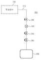
도 3은 도 2에 도시된 진공배기장치의 개략적 구성도,3 is a schematic configuration diagram of the vacuum exhaust device shown in FIG.
도 4는 도 3에 도시된 체크밸브의 구성을 개략적으로 도시해 보인 단면도,4 is a cross-sectional view schematically showing the configuration of the check valve shown in FIG.
도 5는 본 발명에 따른 진공배기장치에 장착된 체크밸브의 동작상태를 개략적으로 도시해 보인 단면도이다.5 is a cross-sectional view schematically showing the operating state of the check valve mounted on the vacuum exhaust device according to the present invention.
< 도면의 주요 부분에 대한 부호의 설명 ><Description of Symbols for Main Parts of Drawings>
100 : 진공챔버200 : 진공배기장치100: vacuum chamber 200: vacuum exhaust device
210 : 배기관220 : 고진공펌프210: exhaust pipe 220: high vacuum pump
230 : 건식펌프240 : 고진공밸브230: dry pump 240: high vacuum valve
250 : 개폐밸브260 : 체크밸브250: on-off valve 260: check valve
261 : 밸브몸체262 : 플랜지261: valve body 262: flange
264 : 힌지265 : 밸브디스크264
266 : 밸브시트270 : 콜드트랩266: valve seat 270: cold trap
300 : 저진공 펌핑유닛310 : 진공라인300: low vacuum pumping unit 310: vacuum line
320 : 챔버러핑펌프330 : 러핑밸브320: chamber roughing pump 330: roughing valve
본 발명은 반도체 제조장치에 관한 것으로서, 보다 상세하게는 공정부산물이 진공챔버의 내부로 역류되는 것을 방지하는 역류방지수단이 설치된 진공배기장치에 관한 것이다.BACKGROUND OF THE INVENTION 1. Field of the Invention The present invention relates to a semiconductor manufacturing apparatus, and more particularly, to a vacuum exhaust apparatus provided with backflow preventing means for preventing backflow of a process by-product into an interior of a vacuum chamber.
일반적으로 대부분의 반도체 제조장치는 진공장치이며, 이러한 진공장치에서 식각 또는 증착과 같은 공정을 수행한 후, 진공장치 내부에 잔류하는 불순물을 펌프와 같은 배기장치에 의하여 배출시킨다. 이에 따라 챔버의 내부는 청정한 상태를 유지하면서 진공상태를 유지하게 된다.In general, most semiconductor manufacturing apparatuses are vacuum apparatuses, and after performing processes such as etching or deposition in such vacuum apparatuses, impurities remaining in the vacuum apparatus are discharged by an exhaust apparatus such as a pump. Accordingly, the inside of the chamber is maintained in a vacuum state while maintaining a clean state.
챔버 내부의 진공도는 반도체 제조 공정에 필요한 매우 중요한 조건 중의 하나이며, 특히 최근 반도체 디바이스가 고집적화 되어감에 따라 그 중요도는 점차 높아지고 있다.The degree of vacuum inside the chamber is one of the very important conditions required for the semiconductor manufacturing process, and the importance of the semiconductor device is becoming increasingly important as the semiconductor devices have recently been highly integrated.
도 1은 종래의 통상적인 진공배기장치의 개략적 구성도이다.1 is a schematic configuration diagram of a conventional conventional vacuum exhaust device.
도 1을 참조하면, 종래의 통상적인 진공배기장치는, 진공챔버(10) 내의 각종 공정부산물이 외부로 배출되도록 진공챔버(10)와 연통 설치되는 배기라인(21)과, 배기라인(21) 상에 마련되는 터보분자펌프(22)와, 터보분자펌프(22)의 하류에 배치되는 드라이펌프(23)와, 진공챔버(10)와 터보분자펌프(22) 사이에 설치되는 고진공밸브(24)와, 터보분자펌프(22)와 드라이펌프(23) 사이에 설치되는 포어라인밸브 (25)를 포함한다.Referring to FIG. 1, a conventional vacuum evacuation apparatus includes an
상기와 같은 구성으로 이루어진 종래의 진공배기장치는, 고진공 밸브(24)와 포어라인밸브(25)가 열린 상태에서 터보분자펌프(22)와 드라이펌프(23)의 작동으로 진공챔버(10) 내의 공정가스 및 공정부산물 등을 배기라인(21)을 통해 외부로 배출한다.In the conventional vacuum exhaust device having the above configuration, the operation of the turbo
그런데, 드라이 펌프(23)가 노화 발생이나 자체 결함 등으로 인해 작동을 멈추게 될 경우, 진공챔버(10) 측보다 드라이펌프(23) 측의 압력이 높게되어 각종 공정부산물이 역류하게 된다.By the way, when the
이 경우, 종래의 통상적인 진공배기장치는, 배기라인(21)이 차단되도록 고진공밸브(24)와 포어라인밸브(25)를 개폐동작시킨다. 그러나 공정부산물의 순간적 역류가 발생한 이후에 고진공밸브(24)와 포어라인밸브(25)가 닫히게 된다.In this case, the conventional conventional vacuum exhaust device opens and closes the
이로 인하여, 진공챔버의 내부가 오염되어 진공도가 저하되고, 공정 진행 중인 기판의 손실이 야기되는 등 반도체 제조공정의 공정불량이 발생하는 문제점이 있었다.As a result, the inside of the vacuum chamber is contaminated, the degree of vacuum is lowered, and there is a problem that a process defect of the semiconductor manufacturing process occurs, such as loss of the substrate in process.
따라서, 본 발명은 상술한 바와 같은 종래의 통상적인 진공배기장치가 가진 문제점을 감안하여 이를 해소하기 위해 창출된 것으로서, 본 발명의 목적은 진공챔버의 내부로 공정부산물이 역류하는 것을 방지하여 진공챔버 내의 청정 및 고진공 상태를 유지할 수 있는 진공배기장치를 제공하기 위한 것이다.Therefore, the present invention was created to solve the problem in view of the conventional vacuum exhaust apparatus as described above, the object of the present invention is to prevent the process by-products flow back into the vacuum chamber to prevent the vacuum chamber It is to provide a vacuum exhaust device capable of maintaining a clean and high vacuum state within.
상기한 목적을 달성하기 위하여 본 발명에 의한 진공배기장치는, 진공챔버의 내부를 감압하여 진공상태로 유지시키는 진공배기장치에 있어서, 상기 진공챔버 내의 각종 공정부산물이 외부로 배출되도록 상기 진공챔버와 연통 설치되는 배기관과; 상기 공정부산물을 흡입 배출하도록 상기 배기관 상에 마련되는 고진공펌프와; 상기 고진공펌프로부터 배출된 상기 공정부산물을 펌핑하도록 상기 고진공펌프의 하류에 배치되는 건식펌프와; 상기 진공챔버와 상기 고진공펌프 사이에 배치되어 상기 진공챔버 내의 진공도를 제어하도록 개폐 구동되는 고진공밸브와; 상기 고진공펌프와 상기 건식펌프 사이에 배치되는 개폐밸브와; 상기 건식펌프로부터 상기 공정부산물의 역류를 방지하도록 상기 배기관 상에 배치되는 역류방지수단;을 포함하는 것을 특징으로 한다.In order to achieve the above object, the vacuum exhaust device according to the present invention is a vacuum exhaust device for maintaining a vacuum state by reducing the inside of the vacuum chamber, wherein the vacuum chamber and the various process by-products in the vacuum chamber is discharged to the outside; An exhaust pipe installed in communication; A high vacuum pump provided on the exhaust pipe to suck and discharge the process by-products; A dry pump disposed downstream of the high vacuum pump to pump the process by-product discharged from the high vacuum pump; A high vacuum valve disposed between the vacuum chamber and the high vacuum pump and opened and closed to control the degree of vacuum in the vacuum chamber; An on / off valve disposed between the high vacuum pump and the dry pump; And a backflow preventing means disposed on the exhaust pipe to prevent backflow of the process byproduct from the dry pump.
상술한 바와 같은 구성을 가지는 본 발명에 의한 진공배기장치에 있어서, 상기 역류방지수단은 상기 건식펌프와 상기 개폐밸브 사이에 배치되는 것이 바람직하다.In the vacuum exhaust device according to the present invention having the configuration as described above, the backflow prevention means is preferably disposed between the dry pump and the on-off valve.
본 발명의 일 측면에 따르면, 상기 역류방지수단은 체크밸브를 포함하는 것이 바람직하다.According to one aspect of the invention, the backflow prevention means preferably comprises a check valve.
그리고 상기 체크밸브는, 유로(流路)가 형성된 중공형의 밸브몸체와; 상기 밸브몸체의 양단에 형성되어 상기 배기관과 연결되는 플랜지부와; 상기 밸브몸체의 내측에 힌지 결합되어 상기 유로를 개폐시키는 밸브디스크와; 상기 밸브디스크의 디스크면이 밀착되어 기밀을 유지하도록 상기 밸브몸체의 내측에 돌출 형성된 밸브시트;를 포함하는 것이 바람직하다.The check valve may include a hollow valve body having a flow path formed therein; Flange portions formed at both ends of the valve body and connected to the exhaust pipe; A valve disc hinged to an inner side of the valve body to open and close the flow path; It is preferable to include a; valve seat protruding inside the valve body so that the disk surface of the valve disk is in close contact with the airtight.
본 발명의 일 특징에 따르면, 상기 진공챔버의 내부를 초기 저진공상태로 감압하는 저진공 펌핑유닛을 더 포함하며, 상기 저진공 펌핑유닛은, 상기 진공챔버 내의 각종 공정부산물이 외부로 배출되도록 상기 진공챔버와 연통 설치되는 진공라인과; 상기 공정부산물을 흡입 배출하도록 상기 진공라인 상에 마련되는 챔버러핑펌프와; 상기 진공챔버와 상기 챔버러핑펌프 사이에 배치되어 상기 진공챔버 내의 진공도를 제어하도록 개폐 구동되는 러핑밸브;를 포함하는 것이 바람직하다.According to one feature of the invention, the vacuum chamber further comprises a low vacuum pumping unit for reducing the pressure in the initial low vacuum state, the low vacuum pumping unit, the various process by-products in the vacuum chamber is discharged to the outside A vacuum line in communication with the vacuum chamber; A chamber roughing pump provided on the vacuum line to suck and discharge the process byproduct; And a roughing valve disposed between the vacuum chamber and the chamber roughing pump to open and close to control the degree of vacuum in the vacuum chamber.
이하 첨부된 도면을 참조하여 본 발명의 바람직한 실시예에 따른 진공배기장치를 상세히 설명하기로 한다.Hereinafter, a vacuum exhaust apparatus according to a preferred embodiment of the present invention will be described in detail with reference to the accompanying drawings.
( 실시예 )(Example)
도 2는 본 발명에 따른 진공배기장치가 장착된 반도체 제조장치의 개략적 구성도이고, 도 3은 도 2에 도시된 진공배기장치의 개략적 구성도이며, 도 4는 도 3에 도시된 체크밸브의 구성을 개략적으로 도시해 보인 단면도이다.Figure 2 is a schematic configuration diagram of a semiconductor manufacturing apparatus equipped with a vacuum exhaust device according to the present invention, Figure 3 is a schematic configuration diagram of the vacuum exhaust device shown in Figure 2, Figure 4 is a check valve of Figure 3 It is sectional drawing which shows the structure schematically.
도 2 및 도 3을 참조하면, 본 발명은 진공챔버(100)의 내부를 감압하여 진공상태로 유지시키는 진공배기장치(200)에 관한 것으로서, 배기관(210), 고진공펌프(220), 건식펌프(230), 고진공밸브(240), 개폐밸브(250) 및 역류방지수단을 포함한다.2 and 3, the present invention relates to a
배기관(210)은, 진공챔버(100)와 연통되도록 설치되며, 진공챔버(100) 내에서의 공정 진행 중 발생되는 각종 부산물을 외부로 배출하는 통로 역할을 수행한다.The
고진공펌프(220)는, 진공챔버(100)로부터 공정부산물을 흡입 배출하도록 배 기관(210) 상에 마련된다. 고진공펌프(220)로는 예를 들어 터보분자펌프(TMP:Turbo Molecular Pump) 등이 보편적으로 사용된다. 터보분자펌프(TMP)는 터빈이 달린 것과 같은 형상을 갖는 진공펌프의 일종으로서 보통 저진공영역에서 초고진공영역에 이르기까지 넓은 영역을 커버할 수 있을 뿐 아니라 빠른 속도로 펌핑이 가능하다.The
그리고, 고진공펌프(220)와 진공챔버(100) 사이에는 진공챔버(100)의 내부 압력을 자동으로 제어할 수 있는 자동압력제어기(미도시)가 배치될 수 있다.In addition, an automatic pressure controller (not shown) may be disposed between the
건식펌프(230)는, 고진공펌프(220)로부터 배출된 공정부산물을 펌핑하도록 고진공펌프(220)의 하류에 배치된다. 건식펌프(230)는 고진공펌프(220)에 의해 흡인 배출된 공정가스와 공정부산물 등을 고진공펌프(220)의 후단에서 2차적으로 펌핑함으로써 공정이 진행되는 진공챔버(100)의 내부를 진공상태로 감압할 수 있다.The
고진공밸브(240)는, 진공챔버(100)와 고진공펌프(220) 사이에 배치되어 진공챔버(100) 내의 진공도를 제어하도록 개폐 구동된다.The
그리고, 고진공밸브(240)와 고진공펌프(220) 사이의 배기관(210) 상에는 콜드트랩(미도시)이 설치될 수도 있다. 콜드트랩(270)은 유체의 경로 상에 저온의 고체면을 두어 고체면과 유체 사이의 증기압이나 용해도의 차이에 의해 특정 불순물을 포획, 제거하는 장치이다.In addition, a cold trap (not shown) may be installed on the
개폐밸브(250)는, 고진공펌프(220)와 건식펌프(230) 사이의 배기관(210) 상에 배치되어 배기관(210)의 유로를 개폐하도록 구동된다.The opening /
한편, 건식펌프(230)가 노화 발생이나 자체 결함 등으로 인해 작동을 멈추게 될 경우, 진공챔버(100) 측보다 건식펌프(230) 측의 압력이 높게되어 각종 공정부 산물이 건식펌프(230)로부터 역류하게 되며, 이를 방지하기 위한 역류방지수단이 배기관(210) 상에 설치된다.On the other hand, when the
역류방지수단은, 도 3에 도시된 바와 같이, 건식펌프(230)와 개폐밸브(250) 사이의 배기관(210) 상에 배치될 수 있다. 역류방지수단은 배기관(210) 내 유로의 한쪽 방향으로만 유동이 가능하도록 역방향 유동을 차단시킬 수 있는 체크밸브(260) 등으로 마련될 수 있다.As shown in FIG. 3, the backflow prevention means may be disposed on the
도 4를 참조하면, 체크밸브(260)는, 유로(流路)가 형성된 중공형의 밸브몸체(261)와, 밸브몸체(261)의 양단에 형성되어 배기관(210)과 연결되는 플랜지부(262a,262b)와, 밸브몸체(261)의 내측에 힌지(264) 결합되어 유로를 개폐시키는 밸브디스크(265)와, 밸브디스크(265)의 디스크면이 밀착되어 기밀을 유지하도록 밸브몸체(261)의 내측에 돌출 형성된 밸브시트(266)를 포함한다.Referring to FIG. 4, the
여기서, 도면의 미설명 참조부호(263a, 263b, 267)는 오링(O-Ring)이다.Here,
상기와 같은 구성으로 이루어진 본 발명에 따른 진공배기장치는, 도 2에 도시된 바와 같이, 고진공펌프(220)에 의한 공정부산물의 펌핑 이전에 진공챔버(100)의 내부를 초기 저진공상태로 감압하는 저진공 펌핑유닛(300)을 더 포함할 수 있다.Vacuum exhaust device according to the present invention having the configuration as described above, as shown in Figure 2, before the pumping of the process by-products by the
저진공 펌핑유닛(300)은, 진공챔버(100) 내의 각종 공정부산물이 외부로 배출되도록 진공챔버(100)와 연통 설치되는 진공라인(310)과, 공정부산물을 흡입 배출하도록 진공라인(310) 상에 마련되는 챔버러핑펌프(320)와, 진공챔버(100)와 챔버러핑펌프(320) 사이에 배치되어 진공챔버(100) 내의 진공도를 제어하도록 개폐 구동되는 러핑밸브(330)를 포함한다.The low
상술한 바와 같은 구성을 가지는 본 발명에 따른 진공배기장치의 작용에 대해 설명하면 다음과 같다.Referring to the operation of the vacuum exhaust device according to the present invention having the configuration as described above are as follows.
도 5는 본 발명에 따른 진공배기장치에 장착된 체크밸브의 동작상태를 개략적으로 도시해 보인 단면도이다.5 is a cross-sectional view schematically showing the operating state of the check valve mounted on the vacuum exhaust device according to the present invention.
본 발명에 따른 진공배기장치는, 고진공 밸브(240)와 개폐밸브(250)가 열린 상태에서 고진공펌프(220)와 건식펌프(230)의 작동에 의해 진공챔버(100) 내의 공정가스 및 공정부산물 등을 배기관(210)을 통해 외부로 배출한다.The vacuum exhaust device according to the present invention is a process gas and a process by-product in the
그런데, 건식펌프(230)의 노화 발생이나 자체 결함 등으로 인해 건식펌프(230)가 작동을 멈추게 될 경우, 진공챔버(100)의 내부 압력보다 건식펌프(230) 측의 압력이 높게되어, 각종 공정부산물이 펌핑의 역방향으로 역류하게 된다.However, when the
이때, 도 5에 도시된 바와 같이, 공정부산물의 역류방지수단으로 사용되는 체크밸브(260)의 밸브디스크(265)가 회전하여 밸브시트(266)에 밀착됨으로써 공정부산물의 역방향 흐름을 방지하게 된다. 그리고 콘트롤러(미도시)가 고진공밸브(240)와 개폐밸브(250)를 개폐동작시켜 배기관(210)을 차단시킨다.At this time, as shown in FIG. 5, the
이상의 상세한 설명은 본 발명을 예시하는 것이다. 또한 전술한 내용은 본 발명의 바람직한 실시 형태를 나타내고 설명하는 것에 불과하며, 본 발명은 다양한 다른 조합, 변경 및 환경에서 사용할 수 있다. 그리고, 본 명세서에 개시된 발명의 개념의 범위, 저술한 개시 내용과 균등한 범위 및/또는 당업계의 기술 또는 지식의 범위 내에서 변경 또는 수정이 가능하다. 전술한 실시예들은 본 발명을 실시하는데 있어 최선의 상태를 설명하기 위한 것이며, 본 발명과 같은 다른 발명을 이용하는데 당업계에 알려진 다른 상태로의 실시, 그리고 발명의 구체적인 적용 분야 및 용도에서 요구되는 다양한 변경도 가능하다. 따라서, 이상의 발명의 상세한 설명은 개시된 실시 상태로 본 발명을 제한하려는 의도가 아니다. 또한 첨부된 청구범위는 다른 실시 상태도 포함하는 것으로 해석되어야 한다. The foregoing detailed description illustrates the present invention. In addition, the foregoing description merely shows and describes preferred embodiments of the present invention, and the present invention can be used in various other combinations, modifications, and environments. And, it is possible to change or modify within the scope of the concept of the invention disclosed in this specification, the scope equivalent to the written description, and / or the skill or knowledge in the art. The above-described embodiments are for explaining the best state in carrying out the present invention, the use of other inventions such as the present invention in other state known in the art, and the specific fields of application and uses of the present invention. Various changes are also possible. Accordingly, the detailed description of the invention is not intended to limit the invention to the disclosed embodiments. Also, the appended claims should be construed to include other embodiments.
이상에서 설명한 바와 같이 본 발명에 의하면, 건식펌프와 개폐밸브 사이의 배기관 상에 체크밸브를 포함하는 역류방지수단을 설치하여, 건식펌프의 작동 멈춤에 의해 발생하는 진공챔버 내부로의 공정부산물 역류를 방지함으로써, 진공챔버 내의 청정 및 고진공 상태를 유지할 수 있다.As described above, according to the present invention, a backflow prevention means including a check valve is installed on the exhaust pipe between the dry pump and the on-off valve, and the process by-product backflow into the vacuum chamber generated by the stoppage of the dry pump is prevented. By preventing it, it is possible to maintain a clean and high vacuum state in the vacuum chamber.
Claims (5)
Translated fromKoreanPriority Applications (1)
| Application Number | Priority Date | Filing Date | Title |
|---|---|---|---|
| KR1020050093030AKR20070037880A (en) | 2005-10-04 | 2005-10-04 | Vacuum Exhaust Device |
Applications Claiming Priority (1)
| Application Number | Priority Date | Filing Date | Title |
|---|---|---|---|
| KR1020050093030AKR20070037880A (en) | 2005-10-04 | 2005-10-04 | Vacuum Exhaust Device |
Publications (1)
| Publication Number | Publication Date |
|---|---|
| KR20070037880Atrue KR20070037880A (en) | 2007-04-09 |
Family
ID=38159457
Family Applications (1)
| Application Number | Title | Priority Date | Filing Date |
|---|---|---|---|
| KR1020050093030AWithdrawnKR20070037880A (en) | 2005-10-04 | 2005-10-04 | Vacuum Exhaust Device |
Country Status (1)
| Country | Link |
|---|---|
| KR (1) | KR20070037880A (en) |
Cited By (3)
| Publication number | Priority date | Publication date | Assignee | Title |
|---|---|---|---|---|
| KR101459012B1 (en)* | 2013-05-27 | 2014-11-07 | 이동민 | Roughing valve for vaccuum process |
| CN104667565A (en)* | 2013-12-02 | 2015-06-03 | 住友重机械工业株式会社 | Cold trap |
| WO2015199409A1 (en)* | 2014-06-27 | 2015-12-30 | (주) 씨엠테크 | Vacuum exhaust system of sterilizer |
- 2005
- 2005-10-04KRKR1020050093030Apatent/KR20070037880A/ennot_activeWithdrawn
Cited By (5)
| Publication number | Priority date | Publication date | Assignee | Title |
|---|---|---|---|---|
| KR101459012B1 (en)* | 2013-05-27 | 2014-11-07 | 이동민 | Roughing valve for vaccuum process |
| CN104667565A (en)* | 2013-12-02 | 2015-06-03 | 住友重机械工业株式会社 | Cold trap |
| WO2015199409A1 (en)* | 2014-06-27 | 2015-12-30 | (주) 씨엠테크 | Vacuum exhaust system of sterilizer |
| US10232073B2 (en) | 2014-06-27 | 2019-03-19 | Cmtech Co., Ltd. | Vacuum exhaust system of sterilizer |
| US10617779B2 (en) | 2014-06-27 | 2020-04-14 | Cmtech Co. Ltd. | Vacuum exhaust system of sterilizer |
Similar Documents
| Publication | Publication Date | Title |
|---|---|---|
| TWI377291B (en) | Apparatus and method for control, pumping and abatement for vacuum process chambers | |
| JP5996834B2 (en) | Vacuum exhaust device | |
| JP2010147451A (en) | N2 purge apparatus for foup | |
| JP2010504847A5 (en) | ||
| KR20070037880A (en) | Vacuum Exhaust Device | |
| JP6331078B2 (en) | Pressure reducing device using water-sealed vacuum pump | |
| JP2004052759A (en) | Vacuum pump system and its control method | |
| US8651828B2 (en) | Vacuum pump with combined debris catcher and pressure relief valve | |
| KR200195123Y1 (en) | Vacuum shut-off valve device for semiconductor process chamber | |
| JP2849255B2 (en) | Exhaust system for manufacturing high performance semiconductor and control method thereof | |
| KR20060127320A (en) | Exhaust System of Semiconductor Manufacturing Equipment with Non-Return Valve | |
| JP2001338891A (en) | Apparatus for manufacturing semiconductor device | |
| KR20100073338A (en) | Vacuum pump system for semiconductor process chamber | |
| JP2004141803A (en) | Plasma process apparatus and its chamber seal method | |
| KR20060002353A (en) | Vacuum Systems Used in Semiconductor Manufacturing Process | |
| CN112460285B (en) | Life prolonging device and method for vacuum pressure gauge | |
| KR101809041B1 (en) | A loadlock chamber | |
| KR100567901B1 (en) | Exhaust Manifold in Dry Etch Chamber | |
| KR20070038257A (en) | Exhaust System of Semiconductor Manufacturing Equipment | |
| KR100684879B1 (en) | Substrate processing equipment | |
| KR20030045272A (en) | Apparatus for manufacturing the semiconductor | |
| KR20070055790A (en) | Exhaust System of Semiconductor Manufacturing Equipment | |
| JPH05332285A (en) | Vacuum pump | |
| KR20060113155A (en) | Isolation Valve | |
| KR20070008768A (en) | Exhaust System of Semiconductor Manufacturing Equipment |
Legal Events
| Date | Code | Title | Description |
|---|---|---|---|
| PA0109 | Patent application | Patent event code:PA01091R01D Comment text:Patent Application Patent event date:20051004 | |
| PG1501 | Laying open of application | ||
| PC1203 | Withdrawal of no request for examination | ||
| WITN | Application deemed withdrawn, e.g. because no request for examination was filed or no examination fee was paid |