KR20070028201A - Self-diagnosis information processing system of electric rice cooker - Google Patents
Self-diagnosis information processing system of electric rice cookerDownload PDFInfo
- Publication number
- KR20070028201A KR20070028201AKR1020050128907AKR20050128907AKR20070028201AKR 20070028201 AKR20070028201 AKR 20070028201AKR 1020050128907 AKR1020050128907 AKR 1020050128907AKR 20050128907 AKR20050128907 AKR 20050128907AKR 20070028201 AKR20070028201 AKR 20070028201A
- Authority
- KR
- South Korea
- Prior art keywords
- self
- rice cooker
- diagnostic information
- information
- electric rice
- Prior art date
- Legal status (The legal status is an assumption and is not a legal conclusion. Google has not performed a legal analysis and makes no representation as to the accuracy of the status listed.)
- Granted
Links
Images


Classifications
- A—HUMAN NECESSITIES
- A47—FURNITURE; DOMESTIC ARTICLES OR APPLIANCES; COFFEE MILLS; SPICE MILLS; SUCTION CLEANERS IN GENERAL
- A47J—KITCHEN EQUIPMENT; COFFEE MILLS; SPICE MILLS; APPARATUS FOR MAKING BEVERAGES
- A47J27/00—Cooking-vessels
- A47J27/08—Pressure-cookers; Lids or locking devices specially adapted therefor
- A47J27/0802—Control mechanisms for pressure-cookers
- G—PHYSICS
- G06—COMPUTING OR CALCULATING; COUNTING
- G06Q—INFORMATION AND COMMUNICATION TECHNOLOGY [ICT] SPECIALLY ADAPTED FOR ADMINISTRATIVE, COMMERCIAL, FINANCIAL, MANAGERIAL OR SUPERVISORY PURPOSES; SYSTEMS OR METHODS SPECIALLY ADAPTED FOR ADMINISTRATIVE, COMMERCIAL, FINANCIAL, MANAGERIAL OR SUPERVISORY PURPOSES, NOT OTHERWISE PROVIDED FOR
- G06Q10/00—Administration; Management
- G06Q10/10—Office automation; Time management
- G—PHYSICS
- G06—COMPUTING OR CALCULATING; COUNTING
- G06Q—INFORMATION AND COMMUNICATION TECHNOLOGY [ICT] SPECIALLY ADAPTED FOR ADMINISTRATIVE, COMMERCIAL, FINANCIAL, MANAGERIAL OR SUPERVISORY PURPOSES; SYSTEMS OR METHODS SPECIALLY ADAPTED FOR ADMINISTRATIVE, COMMERCIAL, FINANCIAL, MANAGERIAL OR SUPERVISORY PURPOSES, NOT OTHERWISE PROVIDED FOR
- G06Q10/00—Administration; Management
- G06Q10/20—Administration of product repair or maintenance
- H—ELECTRICITY
- H04—ELECTRIC COMMUNICATION TECHNIQUE
- H04L—TRANSMISSION OF DIGITAL INFORMATION, e.g. TELEGRAPHIC COMMUNICATION
- H04L12/00—Data switching networks
- H04L12/02—Details
- H04L12/12—Arrangements for remote connection or disconnection of substations or of equipment thereof
- H—ELECTRICITY
- H04—ELECTRIC COMMUNICATION TECHNIQUE
- H04L—TRANSMISSION OF DIGITAL INFORMATION, e.g. TELEGRAPHIC COMMUNICATION
- H04L12/00—Data switching networks
- H04L12/28—Data switching networks characterised by path configuration, e.g. LAN [Local Area Networks] or WAN [Wide Area Networks]
- A—HUMAN NECESSITIES
- A47—FURNITURE; DOMESTIC ARTICLES OR APPLIANCES; COFFEE MILLS; SPICE MILLS; SUCTION CLEANERS IN GENERAL
- A47J—KITCHEN EQUIPMENT; COFFEE MILLS; SPICE MILLS; APPARATUS FOR MAKING BEVERAGES
- A47J27/00—Cooking-vessels
- A—HUMAN NECESSITIES
- A47—FURNITURE; DOMESTIC ARTICLES OR APPLIANCES; COFFEE MILLS; SPICE MILLS; SUCTION CLEANERS IN GENERAL
- A47J—KITCHEN EQUIPMENT; COFFEE MILLS; SPICE MILLS; APPARATUS FOR MAKING BEVERAGES
- A47J27/00—Cooking-vessels
- A47J27/08—Pressure-cookers; Lids or locking devices specially adapted therefor
- A47J27/086—Pressure-cookers; Lids or locking devices specially adapted therefor with built-in heating means
- Y—GENERAL TAGGING OF NEW TECHNOLOGICAL DEVELOPMENTS; GENERAL TAGGING OF CROSS-SECTIONAL TECHNOLOGIES SPANNING OVER SEVERAL SECTIONS OF THE IPC; TECHNICAL SUBJECTS COVERED BY FORMER USPC CROSS-REFERENCE ART COLLECTIONS [XRACs] AND DIGESTS
- Y10—TECHNICAL SUBJECTS COVERED BY FORMER USPC
- Y10S—TECHNICAL SUBJECTS COVERED BY FORMER USPC CROSS-REFERENCE ART COLLECTIONS [XRACs] AND DIGESTS
- Y10S220/00—Receptacles
- Y10S220/912—Cookware, i.e. pots and pans
Landscapes
- Engineering & Computer Science (AREA)
- Business, Economics & Management (AREA)
- Human Resources & Organizations (AREA)
- Strategic Management (AREA)
- Entrepreneurship & Innovation (AREA)
- Physics & Mathematics (AREA)
- General Physics & Mathematics (AREA)
- Quality & Reliability (AREA)
- Economics (AREA)
- Tourism & Hospitality (AREA)
- Marketing (AREA)
- General Business, Economics & Management (AREA)
- Operations Research (AREA)
- Theoretical Computer Science (AREA)
- Signal Processing (AREA)
- Computer Networks & Wireless Communication (AREA)
- Food Science & Technology (AREA)
- Data Mining & Analysis (AREA)
- Cookers (AREA)
Abstract
Translated fromKoreanDescription
Translated fromKorean도 1은 종래의 전기밥솥의 구성을 나타낸 구성도이다.1 is a configuration diagram showing the configuration of a conventional electric rice cooker.
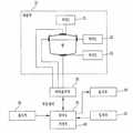
도 2는 본 발명에 따른 자기진단정보 처리 시스템의 개략 구성도이다.2 is a schematic structural diagram of a self-diagnostic information processing system according to the present invention.
도 3은 도 2의 개인단말기의 개략 구성도이다.3 is a schematic configuration diagram of the personal terminal of FIG. 2.
도 4는 도 2의 전기밥솥의 개략 구성도이다.4 is a schematic configuration diagram of the electric rice cooker of FIG.
도 5는 도 2의 메뉴정보서버의 개략 구성도이다.5 is a schematic configuration diagram of the menu information server of FIG. 2.
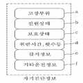
도 6은 자기진단정보의 실시예이다.6 is an embodiment of self-diagnostic information.
도 7은 도 2의 개인단말기와 서비스서버 간의 처리 순서도이다.7 is a flowchart illustrating a process between the personal terminal and the service server of FIG. 2.
도 8은 도 2의 개인단말기와 전기밥솥 간의 처리 순서도이다.8 is a flowchart illustrating a process between the personal terminal and the rice cooker of FIG. 2.
<도면의 주요부분에 대한 설명><Description of main parts of drawing>
100-개인단말기200-전기밥솥100-Individual Terminal 200-Electric Rice Cooker
300-서비스 서버300-service server
본 발명은 전기밥솥의 자기진단정보 처리 시스템에 관한 것으로서, 특히 전기밥솥의 외부에서 소정의 네트워크를 통하여 전기밥솥에 저장된 자기진단정보를 개인단말기로 송신하여 표시함으로써 고장 유무를 판단하도록 하는 전기밥솥의 자기진단정보 처리 시스템에 관한 것이다.The present invention relates to a self-diagnostic information processing system of an electric rice cooker, and in particular, the electric rice cooker to determine whether there is a failure by transmitting the self-diagnostic information stored in the electric rice cooker to a personal terminal through a predetermined network from the outside of the electric rice cooker. A self-diagnostic information processing system.
종래의 전기밥솥은 도 1에서 보는 바와 같이, 각종히터(21;22;23)가 장착된 내솥부(10)와, 상기 각종히터(21;22;23)의 작동을 조절하는 히터출력부(20)와, 상기 내솥부(10)의 내부상태를 감지하는 센서부(30)와, 정보를 저장하는 저장부(40)와, 사용자의 지시 또는 명령을 입력하는 입력부(50)와, 상기 전기밥솥의 상태 및 정보를 표시하는 표시부(60)와, 상기 입력부(50)의 지시 또는 명령과 상기 저장부(40)에 저장된 정보에 따라 상기 히터출력부(20) 및 센서부(30)를 제어하고, 상술한 과정 및 상태를 상기 표시부(60)에 표시하는 제어부(70)를 포함하여 구성된다.The conventional electric rice cooker, as shown in Figure 1, the
상술한 바와 같은 구성에 의한 종래의 전기밥솥은 상기 입력부(50)를 통하여 사용자가 지시 또는 명령을 입력하면 상기 제어부(70)가 상기 저장부(40)에 저장된 정보의 내용에 따라 상기 센서부(30)와 상기 히터출력부(20)를 제어하고, 이에 따라 상기 히터출력부(20)가 상기 각종 히터(21;22;23)를 조절함으로써 취사 또는 보온을 수행하였다.In the conventional electric rice cooker according to the above-described configuration, when the user inputs an instruction or command through the
또한, 상기 전기밥솥은 사용조건에 의존하는 고장이 발생하거나 또는 잠재적으로 고장이 발생할 수 있는 상태에 있을 수 있는데, 이러한 경우 실제 고장시 사용조건을 알 수 없거나, 그 잠재적인 상태를 사용자가 알 수 없을 뿐만 아니라, 고 장원인과 개선에 필요한 정보를 얻을 수 없었다.In addition, the rice cooker may be in a state in which a failure or potential failure may occur depending on the use condition, in which case the user may not know the use condition at the time of the actual breakdown or the potential state of the user. Not only that, there was no information about the cause of the failure and the information needed to improve it.
상술한 바와 같은 문제점을 해결하고자 하는, 본 발명은 사용조건에 의존하는 고장이 발생할 경우, 또는 잠재적인 고장원인이 내재하고 있는지를 진단 할 수 있는 자기진단정보에 대한 처리를 수행하는 전기밥솥의 자기진단정보 처리 시스템을 제공하는 것을 목적으로 한다.In order to solve the problems described above, the present invention is a magnetic cooker of the rice cooker that performs a process for the self-diagnosis information that can diagnose whether a failure depending on the use conditions, or whether there is a potential cause of failure An object of the present invention is to provide a diagnostic information processing system.
또한, 본 발명은 고장 발생 시 및 잠재적인 고장에 대한 동작이상 유무에 대한 확인 및 고장 부위에 대한 조치를 신속하게 할 수 있도록 하는 전기밥솥의 자기진단정보 처리 시스템을 제공하는 것을 목적으로 한다.In addition, an object of the present invention is to provide a self-diagnostic information processing system of an electric rice cooker which can promptly confirm the presence of abnormal operation when the failure occurs and the action on the failure site.
본 발명인 전기밥솥의 자기진단정보 처리 시스템은 전기밥솥의 외부에서 제1네트워크를 통하여 상기 전기밥솥에 연결되어, 상기 전기밥솥으로 자기진단정보를 요청하고, 이후에 상기 전기밥솥으로부터 상기 자기진단정보를 수신하여, 상기 자기진단정보를 표시하는 개인단말기와, 상기 개인단말기와 상기 제1네트워크로 연결되어, 상기 자기진단정보에 대한 요청을 수신하여 기저장된 자기진단정보를 상기 제1네트워크를 통하여 상기 개인단말기로 송신하는 전기밥솥으로 이루어진다.The self-diagnostic information processing system of the electric rice cooker of the present invention is connected to the electric rice cooker through the first network from the outside of the electric rice cooker, and requests the self-diagnostic information to the electric rice cooker, and then the self-diagnostic information from the electric rice cooker A personal terminal receiving and displaying the self-diagnostic information, and connected to the personal terminal and the first network, receiving a request for the self-diagnostic information, and storing previously stored self-diagnostic information through the first network. It consists of an electric rice cooker to send to the terminal.
이때, 상기 제1네트워크는 유선통신 또는 적외선 무선통신 또는 블루투스 무선통신 중 어느 하나인 것이 바람직하다.In this case, the first network is preferably any one of wired communication, infrared wireless communication or Bluetooth wireless communication.
또한, 상기 자기진단정보는 상기 전기밥솥의 히터출력부 및 제어부로부터의 진단정보들과, 상기 전기밥솥의 내부상태를 감지하는 센서감지정보와, 상기 전기밥솥의 제어부 또는 부품 등의 고장유무를 알리는 고장부위정보와, 상기 전기밥솥의 전원공급장치의 상태를 알리는 전원상태정보와, 상기 전원공급장치를 과전압으로부터 보호하는 안전장치의 상태를 알리는 보호상태정보와, 취반시간 및 횟수 등의 이상유무를 알리는 취사메뉴상태정보, 기타 운전정보 중에 적어도 하나 이상을 포함하는 것이 바람직하다.In addition, the self-diagnosis information is diagnostic information from the heater output unit and the control unit of the rice cooker, sensor detection information for detecting the internal state of the rice cooker, and informs the presence or failure of the control unit or parts of the rice cooker, etc. Information on the failure area, power status information indicating the status of the power supply of the rice cooker, protection status information indicating the status of the safety device protecting the power supply from overvoltage, and abnormality such as cooking time and frequency. The notice preferably includes at least one of cooking menu status information and other operation information.
또한, 상기 히터출력부는 취반시에 상기 진단정보를 자체적으로 생성하는 것이 바람직하다.In addition, the heater output unit preferably generates the diagnostic information itself when cooking.
또한, 상기 제어부는 동작 중에 상기 진단정보 또는 취사메뉴상태정보 또는 기타 운전정보 중의 적어도 하나 이상을 자체적으로 생성하는 것이 바람직하다.In addition, the controller preferably generates at least one or more of the diagnostic information, cooking menu status information or other operation information during operation.
또한, 상기 전기밥솥은 사용자에 의해 설정된 서비스 모드에서 상기 요청의 수신 및 자기진단정보의 송신을 수행하는 것이 바람직하다.In addition, the rice cooker preferably performs the reception of the request and the transmission of self-diagnosis information in the service mode set by the user.
또한, 상기 자기진단정보 처리 시스템은 적어도 상기 전기밥솥의 자기진단정보의 판독 및 분석을 수행하는 서비스 서버를 추가적으로 포함하고, 상기 개인단말기는 상기 전기밥솥의 자기진단정보를 제2네트워크를 통하여 상기 서비스 서버로 송신하는 것이 바람직하다.In addition, the self-diagnostic information processing system further includes a service server for performing at least reading and analysis of the self-diagnostic information of the rice cooker, the personal terminal is the service of the self-diagnostic information of the rice cooker via the second network; It is desirable to send to the server.
상술한 바와 같은 구성에 의한 본 발명의 실시례를 첨부된 도면을 참조하여 보다 상세히 설명한다.An embodiment of the present invention having the configuration as described above will be described in more detail with reference to the accompanying drawings.
도 2는 본 발명에 따른 자기진단정보 처리 시스템의 개략 구성도이다. 도 2에 도시된 바와 같이, 자기진단정보 처리 시스템은 제1네트워크를 통하여 전기밥솥(200)에 접속하고, 제2네트워크를 통하여 서비스서버(300)와 접속하는 개인단말기(100)로 이루어진다.2 is a schematic structural diagram of a self-diagnostic information processing system according to the present invention. As shown in FIG. 2, the self-diagnostic information processing system includes a
여기서, 개인단말기(100)는 개인용 컴퓨터(PC), 포터블 컴퓨터, 개인휴대단말기(PDA), 이동통신 단말기, 휴대전화 등이 될 수 있다. 특히, 이 개인단말기(100)는 본 발명에 따른 자기진단정보의 처리를 위한 전용 프로그램을 서비스서버(300)로부터 전송받아 설치함으로써, 그에 따른 자기진단정보를 처리할 수 있도록 한다.Here, the
또한, 제1네트워크는 일반적으로 댁내 또는 소정의 공간에 설치된 전기밥솥(200)과 개인단말기(100) 간의 통신을 위한 것이므로, 소정의 데이터 케이블 등에 의한 유선통신, 적외선 무선통신, 블루투스 무선통신 등이 해당된다.In addition, since the first network is generally for communication between the
또한, 제2네트워크는 개인단말기(100)가 컴퓨터 기반 장치인 경우, 일반적인 인터넷 서비스 제공자 서버와, 인터넷 등을 포괄적으로 의미하고, 전화 기반 장치인 경우, 기지국과, 통신사 서버 및 기타 유선망 등을 포괄적으로 의미하는 것이다.In addition, when the
또한, 전기밥솥(200)은 제1네트워크를 통하여 데이터 통신을 수행하는 통신수단을 구비하고 있어야 한다.In addition, the
또한, 서비스서버(300)는 일반적인 WEB 서버이거나 WAP 서버일 수도 있으며, 개인단말기(100)의 형태에 따른 적합한 서버를 모두 포함하는 의미이다. 이 서비스 서버(300)는 전기밥솥(200)의 제조업체가 관리하는 서버일 수 있다.In addition, the
이하에서, 개인단말기(100), 전기밥솥(200) 및 서비스서버(300)에 대한 상세한 설명이 각각 개시된다.Hereinafter, a detailed description of the
도 3은 도 2의 개인단말기의 개략 구성도이다.3 is a schematic configuration diagram of the personal terminal of FIG. 2.
도 3에 도시된 바와 같이, 개인단말기(100)는 그 장치의 형태에 따른 통신을 수행하여 제2네트워크를 통하여 서비스서버(300)에 접속하기 위한 제1통신부(110)와, 서비스서버(300)에 접속한 후, 자기진단정보 처리를 위한 전용 프로그램과, 전기밥솥(200)으로부터 수신한 자기진단정보를 저장하는 제1저장부(120)와, 사용자로부터의 입력을 수신하는 제1입력부(130)와, 수신된 자기진단정보를 표시하는 제1표시부(140)와, 제1네트워크를 통하여 전기밥솥(200)에 접속하기 위한 부가통신부(150) 및, 상술된 구성요소들을 제어하여, 전기밥솥(200)으로의 자기진단정보의 요청 및 수신, 자기진단정보를 서비스서버(300)로 전송하도록 하는 제1제어부(160)로 이루어진다.As shown in FIG. 3, the
이 개인단말기(100)는 전화통화 및 사무 처리 등의 고유 기능과 함께 서비스서버(300)와의 통신을 위하여 제1통신부(110)와 전기밥솥(200)과의 통신을 위한 부가통신부(150)를 구비하여야 한다. 또한, 제1저장부(120)는 통상 플래쉬 메모리, 하드디스크저장장치, 플로피디스크저장장치, 광디스크저장장치, 광메모리 등이 될 수 있다.The
특히, 제1저장부(120)에 저장된 전용 프로그램은 전기밥솥(200)으로부터의 자기진단정보의 처리를 위한 것으로서, 전기밥솥(200)으로의 자기진단정보의 요청 기능 및 수신기능, 자기진단정보의 서비스서버(300)로의 송신기능, 자기진단정보의 해독기능, 표시기능을 수행하는 프로그램이다.In particular, the dedicated program stored in the first storage unit 120 is for processing the self-diagnosis information from the
도 4는 도 2의 전기밥솥의 개략 구성도이다.4 is a schematic configuration diagram of the electric rice cooker of FIG.
도 4에 도시된 바와 같이, 전기밥솥(200)은 제1네트워크를 통하여 개인단말기(100)와 통신을 수행하는 제2통신부(210)와, 자기진단정보를 저장하는 제2저장부(220)와, 현재의 모드 상태 등을 표시하는 제2표시부(230)와, 사용자로부터의 입력을 획득하는 제2입력부(240)와, 취사메뉴에 따른 조리를 수행하는 히터출력부(250)와, 내솥 등의 온도 또는 압력 등을 감지하는 센서부(260)와, 상술된 구성요소들을 제어하여 진단명령을 히터출력부(250) 또는 센서부(260)로 송신하여 진단정보를 수신하여 저장하고, 개인단말기(100)로부터 저장된 진단정보를 적어도 포함하는 자기진단정보에 대한 전송 요청을 수신하여, 기저장된 자기진단정보를 송신하는 제2제어부(270)로 이루어진다. 도 4에 도시된 구성요소 이외에도, 전기밥솥(200)의 각 부품에 전원을 공급하는 전원공급장치와, 이러한 전원공급장치로부터의 전압에서의 과전압을 방지하기 위한 과전압보호장치(안전장치) 등을 추가적으로 구비한다.As shown in FIG. 4, the
여기서, 제2저장부(220)는 취사메뉴에 대한 정보 및 진단정보 및 자기진단정보 등을 저장하되, MICOM 내부의 기억장치(RAM 또는 FLASH 메모리) 또는 MICOM 외부의 RAM 또는 FLASH 메모리 등이 될 있다. 하기의 도 6과 관련하여, 진단정보 및 자기진단정보를 상세히 개시한다.Here, the
또한, 제2표시부(230)는 현재 설정된 취사 모드 또는 서비스 모드를 사용자가 볼 수 있도록 하는 장치로써, 통상 액정표시장치, TFT 표시장치, 플라즈마표시 장치, 자체발광표시장치 등이 될 수 있다. 특히, 제2표시부(230)는 이러한 디스플레이 장치뿐만 아니라, 제2입력부(240)와 관련되어 제2입력부(240)의 기능을 문자 또는 도형으로 표시하는 전기밥솥(200)의 외부면도 포함한다.In addition, the
특히, 제2입력부(240)는 평소엔 취사관련 기능을 수행하다가, 개인단말기(100)와의 접속을 위해 자기진단정보의 처리를 위한 서비스 모드로 진입하게 하는 기능(설정 및 해제 기능)을 수행한다.In particular, while the
히터출력부(250)는 전기밥솥(200)의 내부에 장착되어 각종히터의 작동을 조절하고, 히터의 상태를 진단하여 진단정보를 생성한다. 특히, 히터출력부(250)는 취반시에 자체적으로 상태를 진단하여 진단정보를 생성할 수도 있고, 제2제어부(270)로부터의 명령에 따라 진단정보를 생성할 수도 있다. 또한, 센서부(260)는 상기 전기밥솥(200)의 내부의 상태를 감지하여 감지정보를 생성한다. 또한, 통상 온도센서와, 중량센서 등으로 구성된다.The heater output unit 250 is mounted inside the
또한, 제2제어부(270)는 취반, 보온 등의 절차를 수행하도록 각 부품(구성요소)을 제어하면서, 동작 중에 자체적으로 진단정보를 생성한다. 즉, 제2제어부(270)는 자신에 대한 고장이나 오류, 다른 부품들의 고장유무를 판단하여 그에 따른 진단정보를 생성하는 기능도 수행한다. 또한, 제2제어부(270)는 히터출력부(250)로의 진단명령의 생성하여 그에 따른 진단정보를 수신할 수도 있다. 물론, 제2제어부(270)는 히터출력부(250)가 자체적으로 수행한 진단정보, 센서부(26)로부터의 감지정보, 전원공급장치로부터의 전원상태정보, 과전압보호장치(안전장치)로부터의 보호상태정보 등을 수신하여 제2저장부(220)에 저장하는 기능도 수행한다. 또 한, 제2제어부는 취반시간 및 횟수 등의 이상유무를 판단하여, 이에 대한 정보를 포함하는 취사메뉴상태정보 등도 생성하여 제2저장부(220)에 저장하는 기능도 수행한다.In addition, the
도 5는 도 2의 메뉴정보서버의 개략 구성도이다.5 is a schematic configuration diagram of the menu information server of FIG. 2.
도 5에 도시된 바와 같이, 서비스서버(300)는 개인단말기(100)에서 서비스서버(300)에 제2네트워크를 통하여 접속한 후 자기진단정보에 대한 처리를 수행할 수 있도록 하는 전용 프로그램을 저장하고, 이 전용 프로그램의 설치가 요구되는 개인단말기(100)로 전용 프로그램이 전송되도록 하는 전용 프로그램 모듈(310)과, 개인단말기(100)로부터 수신된 자기진단정보를 저장하고, 또한, 이들 자기진단정보에 대한 해독 결과, 분석 결과, 해결책 등을 저장하는 자기진단정보 처리 모듈(320)과, 제2네트워크를 통하여 개인단말기(100)와의 접속을 수행하고, 개인단말기(100)로부터의 전용 프로그램의 다운로드, 자기진단정보의 수신 등을 처리하는 통신모듈(330)을 적어도 포함한다. 여기서, 서비스서버(300)는 일반적인 서버의 기능을 기본적으로 수행하고, 전용 프로그램의 처리, 자기진단정보의 처리를 추가적으로 수행한다.As shown in FIG. 5, the
특히, 자기진단정보 처리 모듈(320)은 자기진단정보를 저장하고, 전기밥솥(200)의 모델 및/또는 사용자(사용자 정보, 소유주 정보)에 따라 자기진단정보를 저장한다. 또한, 자기진단정보 처리 모듈(320)은 해독결과 및 분석결과 등을 이 자기진단정보와 연계하여 저장한다.In particular, the self-diagnostic
여기서, 해독 결과는 수신된 자기진단정보 자체에 대한 판독을 의미하며, 분석 결과는 이 판독된 자기진단정보로부터 전기밥솥(200)의 고장여부, 잠재적인 고장(이상)을 판단하는 것을 의미하며, 해결책은 이러한 분석 결과에 따른 해결 방안을 의미한다. 또한, 서비스서버(300)는 이러한 해결결과, 분석결과 및 해결책 등을 다시 개인단말기(100)로 전송하거나, 연동하는 웹페이지 또는 왑페이지에 업로드할 수도 있다.Here, the decryption result refers to reading the received self-diagnosis information itself, and the analysis result means to determine whether the
도 6은 자기진단정보의 실시예이다. 도 6에 도시된 바와 같이, 전기밥솥(200)에서 개인단말기(200)로 송신되는 자기진단정보는 히터출력부(250)로부터의 진단정보(미도시) 이외에도, 전기밥솥(200)의 제2제어부(270) 또는 부품(히터출력부(250), 센서부(260) 등) 등의 고장유무를 알리는 고장부위정보(a)와, 전기밥솥(200)의 전원공급장치의 상태를 알리는 전원상태정보(b)와, 전원공급장치를 과전압으로부터 보호하는 안전장치의 상태를 알리는 보호상태정보(c)와, 취반시간 및 횟수 등의 이상유무를 알리는 취사메뉴상태정보(d)와, 센서부(26)로부터의 온도정보, 중량정보 등을 포함하는 감지정보(e), 기타운전정보(f) 중의 적어도 하나 이상을 추가적으로 포함한다.6 is an embodiment of self-diagnostic information. As shown in FIG. 6, the self-diagnosis information transmitted from the
또한, 전기밥솥(200)의 제2저장부(220)는 제품정보(예를 들면, 제품 모델 정보, 제조연월일, 취사메뉴정보 등)를 저장하고, 자기진단정보는 이러한 제품정보를 추가적으로 포함하여, 개인단말기(100)의 제1제어부(160)가 이러한 제품정보를 참조하여 자기진단정보를 해독하여 표시할 수도 있다.In addition, the
도 7은 도 2의 개인단말기와 서비스 서버 간의 처리 순서도이다.7 is a flowchart illustrating a process between the personal terminal and the service server of FIG. 2.
자세하게는, 단계(S71)에서, 개인단말기(100)의 제1제어부(160)는 사용자의 접속 명령에 따라 제1통신부(110)를 제어하여 제2네트워크를 통하여 서비스서버(300)의 통신모듈(330)에 접속한다. 이에, 서비스서버(300)는 일반적인 초기화면정보 등을 개인단말기(100)에 송신할 수도 있다.In detail, in step S71, the first controller 160 of the
단계(S72)에서, 개인단말기(100)의 제1제어부(160)는 자기진단정보의 처리를 위한 전용 프로그램이 제1저장부(120)에 설치되었는지를 판단한다. 이 전용 프로그램은 자기진단정보의 처리(요청, 송수신, 해독, 표시 등)를 용이하게 하기 위한 것이다. 만약 설치되어 있으면 종료되고, 그렇지 않으면 단계(S73)로 진행한다.In operation S72, the first control unit 160 of the
단계(S73)에서, 개인단말기(100)의 제1제어부(160)는 전용 프로그램의 다운로드를 제1통신부(110)를 통하여 서비스서버(300)에 요청하고, 이에 서비스서버(300)의 전용 프로그램 모듈(310)은 이 요청에 따라 기저장된 전용 프로그램을 통신모듈(330)을 통하여 전송한다. 제1제어부(160)는 이 전용 프로그램을 수신하여 제1저장부(120)에 설치한다.In step S73, the first control unit 160 of the
도 8은 도 2의 개인단말기와 전기밥솥 간의 처리 순서도이다.8 is a flowchart illustrating a process between the personal terminal and the rice cooker of FIG. 2.
자세하게는, 단계(S81)에서, 전기밥솥(200)의 제2제어부(270)는 히터출력부(250)에 대한 진단명령을 생성하여 전송한다.In detail, in step S81, the
단계(S82)에서, 히터출력부(250)는 진단명령에 따른 진단을 수행하여 그 결과인 진단정보를 제2제어부(270)로 송신하고, 제2제어부(270)는 진단정보를 제2저장부(220)에 저장한다. 또한, 제2제어부(270)는 전기밥솥(200)의 동작 시에 자체적으로 진단정보, 취사메뉴상태정보(d)와 기타 운전정보(f)를 생성하여 제2저장부(220)에 저장한다. 단계(S81) 및 (S82)는 소정의 시간간격으로 지속적으로 수행될 수 있으며, 다른 부품인 센서부(260)로부터의 감지 정보(e)의 수신 및 다른 자기진단정보에 포함되는 정보(a 내지 f)를 수신 또는 생성하여 저장한다. 다만, 히터출력부(250)는 제2제어부(27)로부터의 진단명령없이도 취반 시 자체적으로 진단정보를 생성할 수 있으므로, 단계(S81)는 생략될 수 있다.In step S82, the heater output unit 250 performs a diagnosis according to a diagnosis command and transmits the diagnosis information as a result to the
단계(S83)에서, 제2제어부(270)는 사용자에 의한 제2입력부(240)로부터의 서비스 모드 설정입력이 있었는지를 판단한다. 즉, 전기밥솥(200)의 현재 설정 모드가 서비스 모드인지를 판단하여, 만약 서비스 모드이면 단계(S84)로 진행하고, 그렇지 않으면 대기한다. 이 대기 상태에서 단계(S81) 및 (S82) 등을 지속적으로 수행할 수 있다.In step S83, the
단계(S84)에서, 제2제어부(270)가 개인단말기(100)로부터의 자기진단정보에 대한 요청을 전송하는지를 판단한다. 즉, 제2제어부(270)는 제2통신부(210)를 통하여 제1제어부(160)로부터 이러한 요청을 수신하는지를 판단한다. 여기서, 개인단말기(100)의 제1제어부(160)는 전용 프로그램을 활성화하여, 사용자로부터 제1입력부(130)를 통하여 사용자에 의해 입력된 자기진단정보에 대한 요청을 부가통신부(150)를 통하여 송신한다. 만약 요청이 수신되면 단계(S86)로 진행하고, 그렇지 않으면 단계(S85)로 진행한다.In step S84, it is determined whether the
단계(S85)에서, 제2제어부(270)는 단계(S83) 이후에 서비스 모드가 해제되었는지를 판단하여, 만약 서비스 모드가 해제되었으면 종료하고, 만약 현재도 서비스 모드이면 단계(S84)로 진행하여 개인단말기(100)로부터의 요청의 수신을 대기한다.In step S85, the
단계(S86)에서, 제2제어부(270)는 자기진단정보의 요청에 따라 제2저장부 (220)에 저장된 자기진단정보를 생성하거나 판독하여 개인단말기(100)로 송신한다. 이때의 자기진단정보는 제품정보를 포함할 수도 있다.In operation S86, the
단계(S87)에서, 개인단말기(100)의 제1제어부(160)는 부가통신부(150)를 통하여 자기진단정보를 수신하여, 전용 프로그램의 동작에 따른 자기진단정보의 해독 결과, 또는 판독 결과를 제1표시부(140)에 표시한다.In step S87, the first control unit 160 of the
이후에, 개인단말기(100)는 제2네트워크를 통하여, 서비스서버(300)에 접속하고, 제1저장부(120)에 저장된 자기진단정보를 서비스서버(300)에 송신하고, 서비스 서버(300)의 자기진단정보 처리 모듈(320)은 수신된 자기진단정보에 대한 처리를 수행하여 저장한다. 개인단말기(100)가 서비스서버(300)로 자기진단정보를 송신할 때, 만약 기저장된 자기진단정보가 제품정보를 포함하지 않은 경우, 사용자로부터의 입력을 제1입력부(130)를 통하여 획득할 수도 있다. 또한, 개인단말기(100)로부터 서비스 서버(300)로의 자기진단정보는 추가적으로 전기밥솥(200)의 소유주에 대한 정보(사용자 정보 또는 소유주 정보)를 포함할 수 있다. 이러한 정보의 추가를 위해, 사용자 또는 소유주가 전화번호, 주소, 이메일 등을 포함하는 정보를 제1입력부(130)를 통하여 입력하고, 제1제어부(160)가 이러한 정보를 자기진단정보에 포함시켜 송신할 수도 있다.Thereafter, the
또한, 서비스서버(300)는 자기진단정보를 자기진단정보 처리 모듈(320)에 따라 처리하고, 소정의 결과(해독결과, 분석결과, 해결책 등)를 개인단말기(100) 또는 사용자 또는 소유주의 이메일로 송신할 수도 있다.In addition, the
이상 설명한 바와 같이, 본 발명은 상술한 특정의 바람직한 실시례에 한정되지 아니하며, 청구범위에서 청구하는 본 발명의 요지를 벗어남 없이 당해 발명이 속하는 기술 분야에서 통상의 지식을 가진 자라면 누구든지 다양한 변형의 실시가 가능한 것은 물론이고, 상술한 실시례로부터 자명하게 유추될 수 있는 것을 모두 포함하여 본 발명의 청구범위 기재의 범위에 있게 된다.As described above, the present invention is not limited to the above-described specific preferred embodiments, and various modifications can be made by those skilled in the art without departing from the gist of the present invention claimed in the claims. It goes without saying that the present invention can be carried out, and all the things that can be obviously inferred from the above-described embodiments are within the scope of the claims.
이러한 구성의 본 발명은 사용조건에 의존하는 고장이 발생할 경우, 실제 고장시 사용조건을 진단하여 고장원인과 개선에 필요한 정보를 얻도록 하는 효과가 있다.The present invention having such a configuration has an effect of obtaining information necessary for failure cause and improvement by diagnosing the use condition when a failure occurs depending on the use condition.
또한, 본 발명은 고장시 자기진단기능으로 동작이상 유무 또는 고장부위를 효과적으로 수리할 수 있도록 하는 효과가 있다.In addition, the present invention has the effect of enabling the self-diagnostic function at the time of failure to effectively repair the presence or failure of the operation.
또한, 본 발명은 전기밥솥의 소유주가 직접 그 고장 또는 이상 유무를 판단하는 것이 아니라, 사용자(수리기술자)가 전기밥솥에 저장된 자기진단정보를 활용하여 신속하고 정확하게 판단할 수 있도록 할 뿐만 아니라, 서비스 서버를 통하여 보다 체계적이고 정확한 제품관리가 이루어지도록 하는 효과가 있다.In addition, the present invention, the owner of the rice cooker does not directly determine whether there is a failure or abnormality, the user (repair technician) to make a quick and accurate judgment using the self-diagnosis information stored in the rice cooker, as well as service It is effective to make more systematic and accurate product management through the server.
또한, 본 발명은 서비스 서버가 자기진단정보를 판독 및 처리하여 고장 진단 및 수리 등의 애프터서비스가 필요한지를 제조업체에서 판단할 수 있도록 하고, 소유주의 가정에 방문하여 전기밥솥의 고장을 수리하여 유지 보수할 수 있는 정보를 제공하는 효과가 있다.In addition, the present invention allows the manufacturer to determine whether the after-sales service, such as failure diagnosis and repair is required by the service server reads and processes the self-diagnostic information, and visits the owner's home to repair the breakdown of the rice cooker and maintenance It has the effect of providing information that can be done.
Claims (7)
Translated fromKoreanPriority Applications (2)
| Application Number | Priority Date | Filing Date | Title |
|---|---|---|---|
| JP2006151940AJP2007167619A (en) | 2005-12-23 | 2006-05-31 | Self-diagnosis information processing system for electric rice cookers |
| CN 200610107751CN1988515A (en) | 2005-12-23 | 2006-07-21 | Self-diagnosing information processing system of rice cooker |
Applications Claiming Priority (2)
| Application Number | Priority Date | Filing Date | Title |
|---|---|---|---|
| KR20050083367 | 2005-09-07 | ||
| KR1020050083367 | 2005-09-07 |
Publications (2)
| Publication Number | Publication Date |
|---|---|
| KR20070028201Atrue KR20070028201A (en) | 2007-03-12 |
| KR100746448B1 KR100746448B1 (en) | 2007-08-03 |
Family
ID=38101094
Family Applications (2)
| Application Number | Title | Priority Date | Filing Date |
|---|---|---|---|
| KR1020050128119AActiveKR100746405B1 (en) | 2005-09-07 | 2005-12-22 | Cooking menu information processing system of a electrical rice pot |
| KR1020050128907AActiveKR100746448B1 (en) | 2005-09-07 | 2005-12-23 | Electrical rice pot with self-diagnosing information processing function |
Family Applications Before (1)
| Application Number | Title | Priority Date | Filing Date |
|---|---|---|---|
| KR1020050128119AActiveKR100746405B1 (en) | 2005-09-07 | 2005-12-22 | Cooking menu information processing system of a electrical rice pot |
Country Status (1)
| Country | Link |
|---|---|
| KR (2) | KR100746405B1 (en) |
Cited By (45)
| Publication number | Priority date | Publication date | Assignee | Title |
|---|---|---|---|---|
| US9058653B1 (en) | 2011-06-10 | 2015-06-16 | Flir Systems, Inc. | Alignment of visible light sources based on thermal images |
| US9143703B2 (en) | 2011-06-10 | 2015-09-22 | Flir Systems, Inc. | Infrared camera calibration techniques |
| US9207708B2 (en) | 2010-04-23 | 2015-12-08 | Flir Systems, Inc. | Abnormal clock rate detection in imaging sensor arrays |
| US9208542B2 (en) | 2009-03-02 | 2015-12-08 | Flir Systems, Inc. | Pixel-wise noise reduction in thermal images |
| US9235023B2 (en) | 2011-06-10 | 2016-01-12 | Flir Systems, Inc. | Variable lens sleeve spacer |
| US9235876B2 (en) | 2009-03-02 | 2016-01-12 | Flir Systems, Inc. | Row and column noise reduction in thermal images |
| US9292909B2 (en) | 2009-06-03 | 2016-03-22 | Flir Systems, Inc. | Selective image correction for infrared imaging devices |
| USD765081S1 (en) | 2012-05-25 | 2016-08-30 | Flir Systems, Inc. | Mobile communications device attachment with camera |
| US9451183B2 (en) | 2009-03-02 | 2016-09-20 | Flir Systems, Inc. | Time spaced infrared image enhancement |
| US9473681B2 (en) | 2011-06-10 | 2016-10-18 | Flir Systems, Inc. | Infrared camera system housing with metalized surface |
| US9509924B2 (en) | 2011-06-10 | 2016-11-29 | Flir Systems, Inc. | Wearable apparatus with integrated infrared imaging module |
| US9517679B2 (en) | 2009-03-02 | 2016-12-13 | Flir Systems, Inc. | Systems and methods for monitoring vehicle occupants |
| US9521289B2 (en) | 2011-06-10 | 2016-12-13 | Flir Systems, Inc. | Line based image processing and flexible memory system |
| US9635285B2 (en) | 2009-03-02 | 2017-04-25 | Flir Systems, Inc. | Infrared imaging enhancement with fusion |
| US9635220B2 (en) | 2012-07-16 | 2017-04-25 | Flir Systems, Inc. | Methods and systems for suppressing noise in images |
| US9674458B2 (en) | 2009-06-03 | 2017-06-06 | Flir Systems, Inc. | Smart surveillance camera systems and methods |
| US9706139B2 (en) | 2011-06-10 | 2017-07-11 | Flir Systems, Inc. | Low power and small form factor infrared imaging |
| US9706137B2 (en) | 2011-06-10 | 2017-07-11 | Flir Systems, Inc. | Electrical cabinet infrared monitor |
| US9706138B2 (en) | 2010-04-23 | 2017-07-11 | Flir Systems, Inc. | Hybrid infrared sensor array having heterogeneous infrared sensors |
| US9716843B2 (en) | 2009-06-03 | 2017-07-25 | Flir Systems, Inc. | Measurement device for electrical installations and related methods |
| US9723227B2 (en) | 2011-06-10 | 2017-08-01 | Flir Systems, Inc. | Non-uniformity correction techniques for infrared imaging devices |
| US9756264B2 (en) | 2009-03-02 | 2017-09-05 | Flir Systems, Inc. | Anomalous pixel detection |
| US9756262B2 (en) | 2009-06-03 | 2017-09-05 | Flir Systems, Inc. | Systems and methods for monitoring power systems |
| US9807319B2 (en) | 2009-06-03 | 2017-10-31 | Flir Systems, Inc. | Wearable imaging devices, systems, and methods |
| US9811884B2 (en) | 2012-07-16 | 2017-11-07 | Flir Systems, Inc. | Methods and systems for suppressing atmospheric turbulence in images |
| US9819880B2 (en) | 2009-06-03 | 2017-11-14 | Flir Systems, Inc. | Systems and methods of suppressing sky regions in images |
| US9843742B2 (en) | 2009-03-02 | 2017-12-12 | Flir Systems, Inc. | Thermal image frame capture using de-aligned sensor array |
| US9848134B2 (en) | 2010-04-23 | 2017-12-19 | Flir Systems, Inc. | Infrared imager with integrated metal layers |
| US9900526B2 (en) | 2011-06-10 | 2018-02-20 | Flir Systems, Inc. | Techniques to compensate for calibration drifts in infrared imaging devices |
| US9918023B2 (en) | 2010-04-23 | 2018-03-13 | Flir Systems, Inc. | Segmented focal plane array architecture |
| US9948872B2 (en) | 2009-03-02 | 2018-04-17 | Flir Systems, Inc. | Monitor and control systems and methods for occupant safety and energy efficiency of structures |
| US9961277B2 (en) | 2011-06-10 | 2018-05-01 | Flir Systems, Inc. | Infrared focal plane array heat spreaders |
| US9973692B2 (en) | 2013-10-03 | 2018-05-15 | Flir Systems, Inc. | Situational awareness by compressed display of panoramic views |
| US9986175B2 (en) | 2009-03-02 | 2018-05-29 | Flir Systems, Inc. | Device attachment with infrared imaging sensor |
| US9998697B2 (en) | 2009-03-02 | 2018-06-12 | Flir Systems, Inc. | Systems and methods for monitoring vehicle occupants |
| US10051210B2 (en) | 2011-06-10 | 2018-08-14 | Flir Systems, Inc. | Infrared detector array with selectable pixel binning systems and methods |
| US10079982B2 (en) | 2011-06-10 | 2018-09-18 | Flir Systems, Inc. | Determination of an absolute radiometric value using blocked infrared sensors |
| US10091439B2 (en) | 2009-06-03 | 2018-10-02 | Flir Systems, Inc. | Imager with array of multiple infrared imaging modules |
| US10169666B2 (en) | 2011-06-10 | 2019-01-01 | Flir Systems, Inc. | Image-assisted remote control vehicle systems and methods |
| US10244190B2 (en) | 2009-03-02 | 2019-03-26 | Flir Systems, Inc. | Compact multi-spectrum imaging with fusion |
| US10389953B2 (en) | 2011-06-10 | 2019-08-20 | Flir Systems, Inc. | Infrared imaging device having a shutter |
| US10757308B2 (en) | 2009-03-02 | 2020-08-25 | Flir Systems, Inc. | Techniques for device attachment with dual band imaging sensor |
| US10841508B2 (en) | 2011-06-10 | 2020-11-17 | Flir Systems, Inc. | Electrical cabinet infrared monitor systems and methods |
| CN112087352A (en)* | 2019-06-13 | 2020-12-15 | 佛山市顺德区美的电热电器制造有限公司 | Method and device for protecting broken net of cooking equipment |
| US11297264B2 (en) | 2014-01-05 | 2022-04-05 | Teledyne Fur, Llc | Device attachment with dual band imaging sensor |
Families Citing this family (1)
| Publication number | Priority date | Publication date | Assignee | Title |
|---|---|---|---|---|
| KR102754457B1 (en) | 2019-08-26 | 2025-01-17 | 삼성전자주식회사 | Cooking apparatus and controlling method thereof |
Family Cites Families (6)
| Publication number | Priority date | Publication date | Assignee | Title |
|---|---|---|---|---|
| KR980008137A (en)* | 1996-07-12 | 1998-04-30 | 배순훈 | Self-diagnosis method of electric rice cooker |
| KR100209640B1 (en)* | 1996-12-26 | 1999-07-15 | 구자홍 | Apparatus for controlling home automation device by using internet |
| KR100631192B1 (en)* | 1999-08-19 | 2006-10-04 | 삼성전자주식회사 | Microwave and Control Method |
| KR100487406B1 (en)* | 2000-05-23 | 2005-05-03 | (주) 엘지텔레콤 | Control system in home network and control method using the same |
| JP2002340664A (en)* | 2001-05-14 | 2002-11-27 | Shimadzu Corp | Electronic balance |
| JP2003284640A (en)* | 2002-03-28 | 2003-10-07 | Toshiba Home Technology Corp | Cooking device |
- 2005
- 2005-12-22KRKR1020050128119Apatent/KR100746405B1/enactiveActive
- 2005-12-23KRKR1020050128907Apatent/KR100746448B1/enactiveActive
Cited By (52)
| Publication number | Priority date | Publication date | Assignee | Title |
|---|---|---|---|---|
| US9635285B2 (en) | 2009-03-02 | 2017-04-25 | Flir Systems, Inc. | Infrared imaging enhancement with fusion |
| US10757308B2 (en) | 2009-03-02 | 2020-08-25 | Flir Systems, Inc. | Techniques for device attachment with dual band imaging sensor |
| US10244190B2 (en) | 2009-03-02 | 2019-03-26 | Flir Systems, Inc. | Compact multi-spectrum imaging with fusion |
| US9208542B2 (en) | 2009-03-02 | 2015-12-08 | Flir Systems, Inc. | Pixel-wise noise reduction in thermal images |
| US10033944B2 (en) | 2009-03-02 | 2018-07-24 | Flir Systems, Inc. | Time spaced infrared image enhancement |
| US9235876B2 (en) | 2009-03-02 | 2016-01-12 | Flir Systems, Inc. | Row and column noise reduction in thermal images |
| US9998697B2 (en) | 2009-03-02 | 2018-06-12 | Flir Systems, Inc. | Systems and methods for monitoring vehicle occupants |
| US9986175B2 (en) | 2009-03-02 | 2018-05-29 | Flir Systems, Inc. | Device attachment with infrared imaging sensor |
| US9451183B2 (en) | 2009-03-02 | 2016-09-20 | Flir Systems, Inc. | Time spaced infrared image enhancement |
| US9948872B2 (en) | 2009-03-02 | 2018-04-17 | Flir Systems, Inc. | Monitor and control systems and methods for occupant safety and energy efficiency of structures |
| US9843742B2 (en) | 2009-03-02 | 2017-12-12 | Flir Systems, Inc. | Thermal image frame capture using de-aligned sensor array |
| US9517679B2 (en) | 2009-03-02 | 2016-12-13 | Flir Systems, Inc. | Systems and methods for monitoring vehicle occupants |
| US9756264B2 (en) | 2009-03-02 | 2017-09-05 | Flir Systems, Inc. | Anomalous pixel detection |
| US9807319B2 (en) | 2009-06-03 | 2017-10-31 | Flir Systems, Inc. | Wearable imaging devices, systems, and methods |
| US9756262B2 (en) | 2009-06-03 | 2017-09-05 | Flir Systems, Inc. | Systems and methods for monitoring power systems |
| US9674458B2 (en) | 2009-06-03 | 2017-06-06 | Flir Systems, Inc. | Smart surveillance camera systems and methods |
| US10091439B2 (en) | 2009-06-03 | 2018-10-02 | Flir Systems, Inc. | Imager with array of multiple infrared imaging modules |
| US9292909B2 (en) | 2009-06-03 | 2016-03-22 | Flir Systems, Inc. | Selective image correction for infrared imaging devices |
| US9716843B2 (en) | 2009-06-03 | 2017-07-25 | Flir Systems, Inc. | Measurement device for electrical installations and related methods |
| US9843743B2 (en) | 2009-06-03 | 2017-12-12 | Flir Systems, Inc. | Infant monitoring systems and methods using thermal imaging |
| US9819880B2 (en) | 2009-06-03 | 2017-11-14 | Flir Systems, Inc. | Systems and methods of suppressing sky regions in images |
| US9207708B2 (en) | 2010-04-23 | 2015-12-08 | Flir Systems, Inc. | Abnormal clock rate detection in imaging sensor arrays |
| US9706138B2 (en) | 2010-04-23 | 2017-07-11 | Flir Systems, Inc. | Hybrid infrared sensor array having heterogeneous infrared sensors |
| US9918023B2 (en) | 2010-04-23 | 2018-03-13 | Flir Systems, Inc. | Segmented focal plane array architecture |
| US9848134B2 (en) | 2010-04-23 | 2017-12-19 | Flir Systems, Inc. | Infrared imager with integrated metal layers |
| US9900526B2 (en) | 2011-06-10 | 2018-02-20 | Flir Systems, Inc. | Techniques to compensate for calibration drifts in infrared imaging devices |
| US9706137B2 (en) | 2011-06-10 | 2017-07-11 | Flir Systems, Inc. | Electrical cabinet infrared monitor |
| US10841508B2 (en) | 2011-06-10 | 2020-11-17 | Flir Systems, Inc. | Electrical cabinet infrared monitor systems and methods |
| US9521289B2 (en) | 2011-06-10 | 2016-12-13 | Flir Systems, Inc. | Line based image processing and flexible memory system |
| US9509924B2 (en) | 2011-06-10 | 2016-11-29 | Flir Systems, Inc. | Wearable apparatus with integrated infrared imaging module |
| US9723227B2 (en) | 2011-06-10 | 2017-08-01 | Flir Systems, Inc. | Non-uniformity correction techniques for infrared imaging devices |
| US9723228B2 (en) | 2011-06-10 | 2017-08-01 | Flir Systems, Inc. | Infrared camera system architectures |
| US9538038B2 (en) | 2011-06-10 | 2017-01-03 | Flir Systems, Inc. | Flexible memory systems and methods |
| US9716844B2 (en) | 2011-06-10 | 2017-07-25 | Flir Systems, Inc. | Low power and small form factor infrared imaging |
| US9473681B2 (en) | 2011-06-10 | 2016-10-18 | Flir Systems, Inc. | Infrared camera system housing with metalized surface |
| US9961277B2 (en) | 2011-06-10 | 2018-05-01 | Flir Systems, Inc. | Infrared focal plane array heat spreaders |
| US9143703B2 (en) | 2011-06-10 | 2015-09-22 | Flir Systems, Inc. | Infrared camera calibration techniques |
| US10389953B2 (en) | 2011-06-10 | 2019-08-20 | Flir Systems, Inc. | Infrared imaging device having a shutter |
| US9058653B1 (en) | 2011-06-10 | 2015-06-16 | Flir Systems, Inc. | Alignment of visible light sources based on thermal images |
| US9235023B2 (en) | 2011-06-10 | 2016-01-12 | Flir Systems, Inc. | Variable lens sleeve spacer |
| US10051210B2 (en) | 2011-06-10 | 2018-08-14 | Flir Systems, Inc. | Infrared detector array with selectable pixel binning systems and methods |
| US10079982B2 (en) | 2011-06-10 | 2018-09-18 | Flir Systems, Inc. | Determination of an absolute radiometric value using blocked infrared sensors |
| US9706139B2 (en) | 2011-06-10 | 2017-07-11 | Flir Systems, Inc. | Low power and small form factor infrared imaging |
| US10169666B2 (en) | 2011-06-10 | 2019-01-01 | Flir Systems, Inc. | Image-assisted remote control vehicle systems and methods |
| US10230910B2 (en) | 2011-06-10 | 2019-03-12 | Flir Systems, Inc. | Infrared camera system architectures |
| US10250822B2 (en) | 2011-06-10 | 2019-04-02 | Flir Systems, Inc. | Wearable apparatus with integrated infrared imaging module |
| USD765081S1 (en) | 2012-05-25 | 2016-08-30 | Flir Systems, Inc. | Mobile communications device attachment with camera |
| US9635220B2 (en) | 2012-07-16 | 2017-04-25 | Flir Systems, Inc. | Methods and systems for suppressing noise in images |
| US9811884B2 (en) | 2012-07-16 | 2017-11-07 | Flir Systems, Inc. | Methods and systems for suppressing atmospheric turbulence in images |
| US9973692B2 (en) | 2013-10-03 | 2018-05-15 | Flir Systems, Inc. | Situational awareness by compressed display of panoramic views |
| US11297264B2 (en) | 2014-01-05 | 2022-04-05 | Teledyne Fur, Llc | Device attachment with dual band imaging sensor |
| CN112087352A (en)* | 2019-06-13 | 2020-12-15 | 佛山市顺德区美的电热电器制造有限公司 | Method and device for protecting broken net of cooking equipment |
Also Published As
| Publication number | Publication date |
|---|---|
| KR20070028200A (en) | 2007-03-12 |
| KR100746448B1 (en) | 2007-08-03 |
| KR100746405B1 (en) | 2007-08-03 |
Similar Documents
| Publication | Publication Date | Title |
|---|---|---|
| KR100746448B1 (en) | Electrical rice pot with self-diagnosing information processing function | |
| JP2007167619A (en) | Self-diagnosis information processing system for electric rice cookers | |
| CA2807580C (en) | Internet based spa networking system having wireless spa nodes | |
| CA2976871A1 (en) | Method and system for data collection and data management | |
| JP7031251B2 (en) | Remote monitoring system and relay device used for it | |
| JP2013169379A (en) | Maintenance system for washing machine | |
| US11801960B2 (en) | System for wireless monitoring of operating and production parameters of a machine for food production | |
| JP6956537B2 (en) | Maintenance system and maintenance method for housing equipment | |
| JP6390135B2 (en) | Hot water system | |
| JP7095779B2 (en) | Maintenance support device and maintenance support method | |
| JP2014030574A (en) | Service management system for washing machine | |
| JP6132870B2 (en) | Home controller, home device management system, notification message display method and program | |
| JP5322170B2 (en) | Communication control method in work machine | |
| JP2017128970A (en) | Irregularity detection system | |
| US10797978B2 (en) | Communication adapter and connection test run method therefor | |
| KR20190051911A (en) | Electrical rice pot with self-diagnosing function | |
| KR200426642Y1 (en) | Booster pump control device for automatic detection and remote control of real-time abnormal occurrence using internet network | |
| KR20190031452A (en) | Electrical rice pot with self-diagnosing function | |
| JP3434667B2 (en) | Combustion equipment repair support system | |
| JP2020027546A (en) | Relay device, facility apparatus equipped therewith, and facility apparatus system | |
| JP2010218410A (en) | Apparatus and method for distributing equipment maintenance management information | |
| JP7562991B2 (en) | Battery monitoring device and maintenance method for battery monitoring device | |
| CN212160733U (en) | After-sale service system for electric appliance | |
| JP2004011973A (en) | Network compatible water heater and remote control system for water heater | |
| JP3444737B2 (en) | Combustion equipment repair support equipment |
Legal Events
| Date | Code | Title | Description |
|---|---|---|---|
| A201 | Request for examination | ||
| PA0109 | Patent application | Patent event code:PA01091R01D Comment text:Patent Application Patent event date:20051223 | |
| PA0201 | Request for examination | ||
| E902 | Notification of reason for refusal | ||
| PE0902 | Notice of grounds for rejection | Comment text:Notification of reason for refusal Patent event date:20070112 Patent event code:PE09021S01D | |
| PG1501 | Laying open of application | ||
| E701 | Decision to grant or registration of patent right | ||
| PE0701 | Decision of registration | Patent event code:PE07011S01D Comment text:Decision to Grant Registration Patent event date:20070628 | |
| GRNT | Written decision to grant | ||
| PR0701 | Registration of establishment | Comment text:Registration of Establishment Patent event date:20070730 Patent event code:PR07011E01D | |
| PR1002 | Payment of registration fee | Payment date:20070730 End annual number:3 Start annual number:1 | |
| PG1601 | Publication of registration | ||
| G170 | Re-publication after modification of scope of protection [patent] | ||
| PG1701 | Publication of correction | ||
| PR1001 | Payment of annual fee | Payment date:20100629 Start annual number:4 End annual number:4 | |
| PR1001 | Payment of annual fee | Payment date:20110630 Start annual number:5 End annual number:5 | |
| PR1001 | Payment of annual fee | Payment date:20120627 Start annual number:6 End annual number:6 | |
| FPAY | Annual fee payment | Payment date:20130626 Year of fee payment:7 | |
| PR1001 | Payment of annual fee | Payment date:20130626 Start annual number:7 End annual number:7 | |
| FPAY | Annual fee payment | Payment date:20140630 Year of fee payment:8 | |
| PR1001 | Payment of annual fee | Payment date:20140630 Start annual number:8 End annual number:8 | |
| FPAY | Annual fee payment | Payment date:20150626 Year of fee payment:9 | |
| PR1001 | Payment of annual fee | Payment date:20150626 Start annual number:9 End annual number:9 | |
| FPAY | Annual fee payment | Payment date:20160616 Year of fee payment:10 | |
| PR1001 | Payment of annual fee | Payment date:20160616 Start annual number:10 End annual number:10 | |
| FPAY | Annual fee payment | Payment date:20170628 Year of fee payment:11 | |
| PR1001 | Payment of annual fee | Payment date:20170628 Start annual number:11 End annual number:11 | |
| FPAY | Annual fee payment | Payment date:20190625 Year of fee payment:13 | |
| PR1001 | Payment of annual fee | Payment date:20190625 Start annual number:13 End annual number:13 | |
| PR1001 | Payment of annual fee | Payment date:20220630 Start annual number:16 End annual number:16 | |
| PR1001 | Payment of annual fee | Payment date:20240702 Start annual number:18 End annual number:18 |