KR20070014313A - Home Gateway Device and Home Network System based on Serial Switch - Google Patents
Home Gateway Device and Home Network System based on Serial SwitchDownload PDFInfo
- Publication number
- KR20070014313A KR20070014313AKR1020050068825AKR20050068825AKR20070014313AKR 20070014313 AKR20070014313 AKR 20070014313AKR 1020050068825 AKR1020050068825 AKR 1020050068825AKR 20050068825 AKR20050068825 AKR 20050068825AKR 20070014313 AKR20070014313 AKR 20070014313A
- Authority
- KR
- South Korea
- Prior art keywords
- interface
- serial switch
- identification information
- target device
- data
- Prior art date
- Legal status (The legal status is an assumption and is not a legal conclusion. Google has not performed a legal analysis and makes no representation as to the accuracy of the status listed.)
- Granted
Links
Images


Classifications
- H—ELECTRICITY
- H04—ELECTRIC COMMUNICATION TECHNIQUE
- H04L—TRANSMISSION OF DIGITAL INFORMATION, e.g. TELEGRAPHIC COMMUNICATION
- H04L12/00—Data switching networks
- H04L12/28—Data switching networks characterised by path configuration, e.g. LAN [Local Area Networks] or WAN [Wide Area Networks]
- H04L12/2803—Home automation networks
- H04L12/283—Processing of data at an internetworking point of a home automation network
- H04L12/2834—Switching of information between an external network and a home network
- H—ELECTRICITY
- H04—ELECTRIC COMMUNICATION TECHNIQUE
- H04L—TRANSMISSION OF DIGITAL INFORMATION, e.g. TELEGRAPHIC COMMUNICATION
- H04L12/00—Data switching networks
- H04L12/28—Data switching networks characterised by path configuration, e.g. LAN [Local Area Networks] or WAN [Wide Area Networks]
- H04L12/40—Bus networks
- H04L12/40052—High-speed IEEE 1394 serial bus
- H04L12/40091—Bus bridging
- H—ELECTRICITY
- H04—ELECTRIC COMMUNICATION TECHNIQUE
- H04L—TRANSMISSION OF DIGITAL INFORMATION, e.g. TELEGRAPHIC COMMUNICATION
- H04L49/00—Packet switching elements
- H04L49/30—Peripheral units, e.g. input or output ports
- H—ELECTRICITY
- H04—ELECTRIC COMMUNICATION TECHNIQUE
- H04L—TRANSMISSION OF DIGITAL INFORMATION, e.g. TELEGRAPHIC COMMUNICATION
- H04L69/00—Network arrangements, protocols or services independent of the application payload and not provided for in the other groups of this subclass
- H04L69/30—Definitions, standards or architectural aspects of layered protocol stacks
- H04L69/32—Architecture of open systems interconnection [OSI] 7-layer type protocol stacks, e.g. the interfaces between the data link level and the physical level
- H04L69/321—Interlayer communication protocols or service data unit [SDU] definitions; Interfaces between layers
Landscapes
- Engineering & Computer Science (AREA)
- Computer Networks & Wireless Communication (AREA)
- Signal Processing (AREA)
- Automation & Control Theory (AREA)
- Computing Systems (AREA)
- Computer Security & Cryptography (AREA)
- Small-Scale Networks (AREA)
Abstract
Translated fromKoreanDescription
Translated fromKorean도 1은 다수의 디바이스를 상호 접속하는 PCI 버스의 개념도.1 is a conceptual diagram of a PCI bus interconnecting multiple devices.
도 2는 본 발명의 바람직한 실시예에 따른 홈 게이트웨이 장치의 구성도.2 is a block diagram of a home gateway device according to a preferred embodiment of the present invention.
도 3은 도 2에 도시된 직렬 스위치 보드의 블록도.3 is a block diagram of the serial switch board shown in FIG.
도 4는 본 발명의 바람직하 실시예에 따라 직렬 스위치 버스에 의해 상호 접속되는 홈 네트워크의 개념도.4 is a conceptual diagram of a home network interconnected by a serial switch bus in accordance with a preferred embodiment of the present invention.
본 발명은 직렬 스위치 기반의 홈 게이트웨이 장치 및 홈 네트워크 시스템에 관한 것으로서, 보다 구체적으로는 홈 네트워크 환경에서 충분한 대역폭 및 확장을 보장할 수 있도록 다수 디바이스로부터 수신된 데이터를 직렬 스위치 방식으로 라우팅하는 홈 게이트웨이 장치 및 홈 네트워크 시스템에 관한 것이다.The present invention relates to a serial switch-based home gateway device and a home network system, and more particularly, a home gateway for routing data received from a plurality of devices in a serial switch method to ensure sufficient bandwidth and expansion in a home network environment. Device and home network system.
90년대 초에 개발된 PCI(Peripheral Component Interconnect) 버스는 ISA 버스와 같이 마이크로프로에 대한 의존도가 높은 기존의 로컬버스방식의 여러 단점을 극복하였다. 즉, 이러한 PCI 버스는 I/O 디바이스와 CPU의 특성과 종류에 관계없이 PCI 규격으로 상호간에 정보를 주고받을 수 있도록 한다. 그리고, 고속 반도체 기술과 정보량의 증가에 따라 PCI 버스도 고속화되어 왔으며, 대역폭의 문제점을 해결하기 위해서 AGP, PCI-X와 같이 업그레이드된 표준들이 발표되었다. 그러나, 이들 역시 여러 I/O 디바이스가 버스를 공유하는 병렬(Parallel) 버스 구조로 되어 있기 때문에, 호스트 CPU가 여러 개인 경우에 병목현상이 생기는 문제가 여전히 상존하고 있다.The Peripheral Component Interconnect (PCI) bus, developed in the early 90's, overcomes many of the shortcomings of traditional local buses that rely heavily on micropros, such as the ISA bus. In other words, such a PCI bus enables the PCI standard to exchange information with each other regardless of the characteristics and types of I / O devices and CPUs. In addition, PCI buses have also been speeded up with high-speed semiconductor technology and increased information volume, and upgraded standards such as AGP and PCI-X have been announced to solve bandwidth problems. However, since they also have a parallel bus structure in which multiple I / O devices share a bus, there is still a problem of bottlenecks in case of multiple host CPUs.
이러한 PCI 버스는 PC뿐만 아니라, 셋톱박스, 통신시스템, 실시간 시스템, 공장 자동화 시스템 등 다양한 분야에서 응용되고 있으며, 홈 네트워크 시스템도 이러한 응용 분야 중 하나이다. The PCI bus is used not only in PCs, but also in various fields such as set-top boxes, communication systems, real-time systems, and factory automation systems. Home network systems are one such application field.
한편, 홈 네트워크를 구성하는 디바이스 간에 사용되는 네트워크 프로토콜은 유선과 무선으로 구분할 수 있으며, 유선 기술로는 이더넷, 전력선(PLC), IEEE1394, USB 등이 있고, 무선에는 IEEE 802.11 계열의 무선LAN, HomeRF, Bluetooth, UWB, Zigbee, HiperLAN 등 다양한 표준이 존재한다. 따라서, 홈 게이트웨이는 이와 같이 다양한 네트워크 표준을 지원하는 이기종 디바이스 간에 상호 접속이 가능하도록 데이터 교환을 중계하여야 한다.Meanwhile, network protocols used between devices constituting a home network can be classified into wired and wireless, and wired technologies include Ethernet, power line (PLC), IEEE1394, and USB. , Bluetooth, UWB, Zigbee, HiperLAN and many other standards exist. Thus, home gateways must relay data exchanges to enable interconnection between heterogeneous devices that support these various network standards.
도 1은 다수의 디바이스를 상호 접속하는 PCI 버스의 개념도이다.1 is a conceptual diagram of a PCI bus interconnecting multiple devices.
도시된 바와 같이, PCI버스는 버스를 디바이스끼리 공유하는 병렬 방식이기 때문에, 다수의 디바이스를 수용할 경우 성능의 저하를 가져와 대역폭을 보장하지 못한다. 따라서, 하나의 PCI 버스에 수용 가능한 디바이스 개수에 제한이 있으며, 그 이상의 디바이스를 상호 접속하기 위해서는 PCI 브릿지(Bridge)를 사용하여야 한다. 또한, 홈 네트워크 환경에서 멀티미디어 데이터와 같이 고속의 대용량 데이터를 주고받는 데 있어서는 대역폭의 한계를 드러내고 있다. 즉, 홈 게이트웨이 내부의 I/O 아키텍처로 PCI 버스를 사용할 경우에, 이에 접속된 어느 한 디바이스가 전송을 하면 다른 디바이스는 버스를 사용하지 못하는 치명적인 문제가 존재한다.As shown, since the PCI bus is a parallel scheme in which the bus is shared between devices, when a large number of devices are accommodated, performance of the PCI bus is not guaranteed to guarantee bandwidth. Therefore, there is a limit on the number of devices that can be accommodated on one PCI bus, and a PCI bridge must be used to interconnect more devices. In addition, in the home network environment, the bandwidth is limited when exchanging high-speed large data such as multimedia data. In other words, when the PCI bus is used as the I / O architecture inside the home gateway, there is a fatal problem in that when one device connected to the device transmits, the other device cannot use the bus.
전술한 문제점을 해결하고자, 본 발명은 멀티미디어 데이터와 같이 고속의 대용량 데이터를 교환할 수 있도록 충분한 대역폭을 보장함과 아울러, 다수의 디바이스를 수용할 수 있도록 확장성을 보장하는 홈 네트워크 시스템 및 홈 게이트웨이를 제공하는 데 그 목적이 있다.In order to solve the above-described problems, the present invention provides a home network system and a home gateway that ensures sufficient bandwidth for exchanging high-capacity data such as multimedia data and also expands to accommodate a large number of devices. The purpose is to provide.
전술한 목적을 달성하기 위하여, 본 발명의 제1 측면에 따르면, 다수의 디바이스를 상호 접속하는 직렬 스위치 버스 기반의 홈 게이트웨이 장치가 제공되며, 상기 각 디바이스의 네트워크 프로토콜에 따라 데이터를 송수신하는 복수의 인터페이스부와; 상기 복수의 인터페이스부와 LVDS 인터페이스로 연결되고 상기 복수의 인터페이스부 사이에서 교환되는 데이터를 직렬 스위칭하는 직렬 스위치부를 포함한다. 그리고, 상기 복수의 인터페이스부는 각 디바이스로부터 수신한 데이터에 목적 디바이스의 식별 정보를 포함시켜서 상기 직렬 스위치부로 전달하며, 상기 직렬 스위치부는 상기 목적 디바이스의 식별 정보에 따라 당해 목적 디바이스가 연결된 인터페이스부로 당해 데이터를 직렬 스위칭한다.In order to achieve the above object, according to a first aspect of the present invention, there is provided a serial switch bus-based home gateway device for interconnecting a plurality of devices, a plurality of devices for transmitting and receiving data in accordance with the network protocol of each device An interface unit; And a serial switch unit connected to the plurality of interface units and the LVDS interface and serially switching data exchanged between the plurality of interface units. The plurality of interface units include identification information of the target device in the data received from each device and transmit the identification information to the serial switch unit, and the serial switch unit transmits the data to the interface unit to which the target device is connected according to the identification information of the target device. Switch in series.
이 때, 상기 직렬 스위치부는 스위칭 노드를 구성하는 복수의 스위치 칩을 포함하며, 각 스위치 칩은 스위칭 노드 사이를 링크하는 포트와 상기 인터페이스부를 링크하는 포트를 구비할 수 있다. 그리고, 상기 인터페이스부는 상기 목적 디바이스의 식별 정보로서 포트 ID를 사용하는 것이 바람직하다.In this case, the serial switch unit may include a plurality of switch chips constituting a switching node, each switch chip may include a port for linking between the switching node and a port for linking the interface unit. The interface unit preferably uses a port ID as identification information of the target device.
또한, 상기 인터페이스부는, 각 디바이스의 네트워크 프로토콜에 따라 물리계층(PHY) 및 매체접속계층(MAC) 처리를 수행하는 인터페이스 모듈과; 상기 인터페이스 모듈과 연결되며 각 디바이스와의 데이터 송수신을 위한 상위 계층 처리를 담당하는 네트워크 프로세서와; 상기 네트워크 프로세서에 연결되며 각 디바이스로부터 수신한 데이터에 목적 디바이스의 식별 정보를 포함시켜서 상기 직렬 스위치부로 전송하며, 직렬 스위치로부터 수신한 데이터를 상기 네트워크 프로세서로 전달하는 브릿지를 포함할 수 있다.The interface unit may include an interface module configured to perform a physical layer (PHY) and a medium access layer (MAC) processing according to a network protocol of each device; A network processor connected to the interface module and configured to perform upper layer processing for data transmission and reception with each device; And a bridge connected to the network processor and including identification information of the target device in the data received from each device to the serial switch unit, and transferring the data received from the serial switch to the network processor.
본 발명의 제2 측면에 따르면, 직렬 스위치 버스 기반의 홈 게이트웨이를 이용하여 다수의 디바이스를 상호 접속하는 홈 네트워크 시스템이 제공된다. 이 때, 상기 홈 게이트웨이는 상기 각 디바이스의 네트워크 프로토콜에 따라 데이터를 송수신하는 복수의 인터페이스부와, 상기 복수의 인터페이스부와 LVDS 인터페이스로 연결되고 상기 복수의 인터페이스부 사이에서 교환되는 데이터를 직렬 스위칭하는 직렬 스위치부를 포함한다. 그리고, 상기 복수의 인터페이스부는 각 디바이스로부터 수신한 데이터에 목적 디바이스의 식별 정보를 포함시켜서 상기 직렬 스위치부로 전달하며, 상기 직렬 스위치부는 상기 목적 디바이스의 식별 정보에 따라 당해 목적 디바이스가 연결된 인터페이스부로 당해 데이터를 직렬 스위칭한다.According to a second aspect of the present invention, there is provided a home network system for interconnecting multiple devices using a serial switch bus based home gateway. In this case, the home gateway serially switches a plurality of interface units for transmitting and receiving data according to a network protocol of each device, and data connected to the plurality of interface units and the LVDS interface and exchanged between the plurality of interface units. It includes a series switch unit. The plurality of interface units include identification information of the target device in the data received from each device and transmit the identification information to the serial switch unit, and the serial switch unit transmits the data to the interface unit to which the target device is connected according to the identification information of the target device. Switch in series.
이하, 첨부된 도면을 참조하여 본 발명의 바람직한 실시예를 설명토록 하며, 도면 전체에 걸쳐 동일한 도면 부호는 동일하거나 유사한 구성 요소를 지칭하고 있다.Hereinafter, exemplary embodiments of the present invention will be described with reference to the accompanying drawings, and like reference numerals refer to like or similar components throughout the drawings.
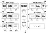
도 2는 본 발명의 바람직한 실시예에 따른 홈 게이트웨이 장치의 구성을 도시한 것으로서, 16포트 직렬 스위치 보드(100)가 백플레인을 구성하고, 홈 네트워크를 구성하는 각 디바이스(도시되지 않음)와 유무선 접속되는 인터페이스 카드(200a, 200b, 200c, 200d, 200e; 이하 "200"이라 총칭함)가 직렬 스위치 보드에 장착되어 있다.2 illustrates a configuration of a home gateway device according to an exemplary embodiment of the present invention, in which a 16-port
직렬 스위치 보드(100)는 예컨대, 16개의 포트를 구비하며, 이들 포트간의 상호 접속을 위해 내부에 네 개의 스위치 칩(110, 120, 130, 140)이 마련되어 있다. 이러한 직렬 스위치 보드의 상세한 구성 및 인터페이스 카드와의 연결은 도 3을 참조하여 후술한다.The
인터페이스 카드(200)는 각각, 인터페이스 모듈(210a, 210b, 210c, 210d, 210e; 이하 "210"이라 총칭함)과, 네트워크 프로세서(220a, 220b, 220c, 220d, 220e; 이하 "220"이라 총칭함)와, 브릿지(230a, 230b, 230c, 230d, 230e; 이하 "230"이라 총칭함)로 이루어져 있다.The interface card 200 is referred to collectively as
인터페이스 모듈(210)은 각 디바이스의 네트워크 프로토콜에 따라 물리계층(PHY) 및 매체접속계층(MAC) 처리를 수행함으로써, 각 디바이스와 데이터를 송수신할 수 있도록 한다. 예컨대, 이러한 인터페이스 모듈로는 도시된 바와 같이, 1394 모듈(210a), PLC 모듈(210b), 센서 모듈(210c), UWB 모듈(210d), 기가비트 이더넷 모듈(210e) 등이 있다.The interface module 210 performs physical layer (PHY) and media access layer (MAC) processing according to the network protocol of each device, thereby enabling data transmission and reception with each device. For example, as illustrated, the interface module includes a 1394
네트워크 프로세서(220)는 인터페이스 모듈(210)과 연결되어 상위 계층 처리를 담당하고, 인터페이스 모듈로부터 송수신되는 데이터를 브릿지(230)와 교환한다. 즉, 네트워크 프로세서는 인터페이스 모듈을 통해 데이터를 수신하여 브릿지에 전달하며, 이 때 해당 네트워크 프로토콜에 따라 목적 디바이스에 관한 정보를 추출하여 함께 전송할 수 있다. 이와 반대로, 네트워크 프로세서는 브릿지로부터 데이터를 수신하면, 인터페이스 모듈을 거쳐 자신과 연결된 디바이스에 데이터를 전송한다.The network processor 220 is connected to the interface module 210 to perform upper layer processing, and exchanges data transmitted and received from the interface module with the bridge 230. That is, the network processor receives the data through the interface module and transfers the data to the bridge. At this time, the network processor may extract information about the target device according to the corresponding network protocol and transmit the information together. On the contrary, when the network processor receives data from the bridge, the network processor transmits data to the device connected thereto via the interface module.
브릿지(230)는 네트워크 프로세서(220)와 데이터를 교환하고, 직렬 스위치 보드(100)에서 스위칭이 수행될 수 있도록 링크 계층(Link Layer)의 프레임 포맷팅을 수행한다. 브릿지(230)에 의해 포맷팅된 프레임의 헤더에는 목적 디바이스의 ID가 포함되며, 이러한 목적 디바이스의 ID로는 라우팅하고자 하는 스위치 칩(110, 120, 130, 140)의 포트 ID를 사용함으로써 어드레스 라우팅을 지원할 수 있다. 한편, 프레임의 페이로드는 가변 길이(Variable-length)인 것이 바람직하며, 이를 지원하기 위해 프레임의 헤더에는 페이로드 크기에 대한 정보가 추가로 포함된다.The bridge 230 exchanges data with the network processor 220 and performs frame formatting of the link layer so that switching may be performed in the
또한, 브릿지(230)는 전술한 바와 같이 포맷팅된 데이터 프레임을 물리 계층 처리하여 자신과 연결된 스위치 칩에 직렬 전송하며, 본 발명의 바람직한 실시예에서는 스위치 칩과 브릿지는 직렬 방식의 LVDS 인터페이스로 연결된다.In addition, the bridge 230 performs a physical layer processing of the data frame formatted as described above, and serially transmits the data frame to the switch chip connected thereto. In the preferred embodiment of the present invention, the switch chip and the bridge are connected to the serial LVDS interface. .
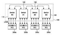
도 3은 도 2에 도시된 16포트 직렬 스위치 보드(100)의 하드웨어 구성, 및 인터페이스 카드(200)와의 연결 관계를 구체적으로 도시한 것이다.FIG. 3 specifically illustrates a hardware configuration of the 16-port
도시된 바와 같이, 직렬 스위치 보드의 각 스위치 칩(110, 120, 130, 140)은 범용 스위치 패브릭인 고속 직렬 스위칭 기능을 제공하며, 고유 ID가 할당된 6개의 포트를 구비한다. 각 포트의 링크는 전이중(Full-duplex) 전송을 지원하며, 단방향으로 네 개의 622Mbps LVDS 차동쌍(Differential Pair)으로 구성된다. 이에 따라, 각 링크는 2.5Gbps 전이중 전송을 지원하며, 총 5Gbps의 속도를 낼 수 있다.As shown, each
각 스위칭 칩의 6개 포트 중에서, 두 개의 포트가 스위칭 노드 간의 링크를 위해 다른 스위치 칩의 포트에 연결되며, 이에 따라 스위칭 노드 간에는 2개의 링크를 사용하여 5Gbps 전이중으로 연결될 수 있다. 그리고, 나머지 4개의 포트는 인터페이스 카드의 브릿지(도 2의 230)와 링크를 구성하는 데 사용된다.Of the six ports of each switching chip, two ports are connected to the ports of the other switch chip for the link between the switching nodes, so that the two nodes can be connected at 5 Gbps full duplex using two links. The remaining four ports are then used to form a link with the bridge of the interface card (230 in FIG. 2).
이러한 스위칭 칩의 동작을 살펴보면, 먼저 자신과 연결된 인터페이스 카드의 브릿지로부터 데이터 프레임을 수신하며, 해당 프레임의 헤더를 검사하여 목적 포트를 판별한다. 그리고 해당 프레임을 목적 포트로 스위칭하여 전송함으로써, 목적 포트를 통해 라우팅하고자 하는 인터페이스 카드에 데이터가 전달된다.Looking at the operation of such a switching chip, first receives a data frame from the bridge of the interface card connected to it, and determines the destination port by examining the header of the frame. By transmitting the frame by switching to the target port, data is transmitted to the interface card to be routed through the target port.
도 4는 전술한 홈 게이트웨이 장치에 의해 제공되는 직렬 스위치 버스에 의해 다수의 디바이스가 상호 접속되는 홈 네트워크를 개념적으로 도시한 것이다.4 conceptually illustrates a home network in which multiple devices are interconnected by a serial switch bus provided by the home gateway device described above.
도시된 바와 같이, 도 2의 홈 게이트웨이 장치는 다수의 디바이스가 상호 접속된 직렬 스위치 버스로서 기능하며, 이러한 직렬 스위치 버스 기술은 임베디드 분산 시스템에 사용할 수 있는 강력한 스위칭 연결 기술(Switched Interconnect Technology)이다. 기존의 병렬방식인 PCI버스는 버스를 디바이스끼리 공유함으로써 성능의 저하를 가져오는데 비해, 본 발명의 바람직한 실시예에 따르면 도 4와 같이 직렬 스위칭 방식을 사용함으로써 각 디바이스에 충분한 대역폭을 보장할 수 있다.As shown, the home gateway device of FIG. 2 functions as a serial switch bus with multiple devices interconnected, and this serial switch bus technology is a powerful switched interconnect technology that can be used in an embedded distributed system. In the conventional parallel PCI bus, the bus is shared between devices, resulting in deterioration in performance. However, according to a preferred embodiment of the present invention, a serial switching scheme as shown in FIG. 4 can ensure sufficient bandwidth for each device. .
또한, 직렬 스위치 버스 기술은 시스템의 확장성과 성능을 획기적으로 향상하며, 트래픽의 클래스를 지원하기 때문에 보다 많은 유연성을 제공하고 지능을 높여준다. 직렬스위칭버스는 PCI와 H.110과 같은 디바이스간의 프로토콜에 상관없이 다양한 트래픽 타입을 지원하며, Class of Service 알고리즘은 여러 종류의 트래픽을 적절하게 제어할 수 있도록 한다. 그리고, 본 발명의 바람직한 실시예에서와 같이 홈 네트워크 시스템에 적용될 경우에는 보다 높은 성능과 확장성을 보장할 수 있다.In addition, serial switch bus technology dramatically improves the scalability and performance of the system, and supports more classes of traffic, providing more flexibility and increased intelligence. The serial switching bus supports a variety of traffic types regardless of protocols between devices such as PCI and H.110, and the Class of Service algorithm enables proper control of various types of traffic. When applied to a home network system as in the preferred embodiment of the present invention, higher performance and scalability can be guaranteed.
이상에서 본 발명에 따른 바람직한 실시예를 설명하였으나, 이는 예시적인 것에 불과하며 당해 분야에서 통상적 지식을 가진 자라면 이로부터 다양한 변형 및 균등한 여타 실시예가 가능하다는 점을 이해할 것이다. 따라서, 본 발명의 보호 범위는 이하의 특허청구범위에 의해서 정해져야 할 것이다.Although the preferred embodiment according to the present invention has been described above, this is merely exemplary and those skilled in the art will understand that various modifications and equivalent other embodiments are possible therefrom. Therefore, the protection scope of the present invention should be defined by the following claims.
이상 설명한 바와 같이, 본 발명에 따라 제공되는 직렬 스위치 버스 기반의 홈 네트워크 시스템 및 홈 게이트웨이 장치는 충분한 대역폭을 보장하기 때문에 멀티미디어 데이터와 같이 고속의 대용량 데이터를 교환하는 데 매우 유리하다. 또한, 충분한 확장성을 보장하기 때문에, 다수의 이기종 디바이스를 홈 네트워크 환경에 효율적으로 통합할 수 있는 장점이 있다.As described above, the home network system and the home gateway device based on the serial switch bus provided in accordance with the present invention are very advantageous for exchanging high-capacity data such as multimedia data because it guarantees sufficient bandwidth. In addition, since it guarantees sufficient scalability, there is an advantage that can efficiently integrate a large number of heterogeneous devices in the home network environment.
Claims (8)
Translated fromKoreanPriority Applications (1)
| Application Number | Priority Date | Filing Date | Title |
|---|---|---|---|
| KR1020050068825AKR100696948B1 (en) | 2005-07-28 | 2005-07-28 | Home Gateway Device and Home Network System based on Serial Switch |
Applications Claiming Priority (1)
| Application Number | Priority Date | Filing Date | Title |
|---|---|---|---|
| KR1020050068825AKR100696948B1 (en) | 2005-07-28 | 2005-07-28 | Home Gateway Device and Home Network System based on Serial Switch |
Publications (2)
| Publication Number | Publication Date |
|---|---|
| KR20070014313Atrue KR20070014313A (en) | 2007-02-01 |
| KR100696948B1 KR100696948B1 (en) | 2007-03-20 |
Family
ID=38080104
Family Applications (1)
| Application Number | Title | Priority Date | Filing Date |
|---|---|---|---|
| KR1020050068825AExpired - Fee RelatedKR100696948B1 (en) | 2005-07-28 | 2005-07-28 | Home Gateway Device and Home Network System based on Serial Switch |
Country Status (1)
| Country | Link |
|---|---|
| KR (1) | KR100696948B1 (en) |
Cited By (1)
| Publication number | Priority date | Publication date | Assignee | Title |
|---|---|---|---|---|
| WO2009039396A3 (en)* | 2007-09-21 | 2009-05-07 | Adc Dsl Sys Inc | Auto-discovery in a switch |
Family Cites Families (1)
| Publication number | Priority date | Publication date | Assignee | Title |
|---|---|---|---|---|
| US5579308A (en)* | 1995-11-22 | 1996-11-26 | Samsung Electronics, Ltd. | Crossbar/hub arrangement for multimedia network |
- 2005
- 2005-07-28KRKR1020050068825Apatent/KR100696948B1/ennot_activeExpired - Fee Related
Cited By (2)
| Publication number | Priority date | Publication date | Assignee | Title |
|---|---|---|---|---|
| WO2009039396A3 (en)* | 2007-09-21 | 2009-05-07 | Adc Dsl Sys Inc | Auto-discovery in a switch |
| US8462661B2 (en) | 2007-09-21 | 2013-06-11 | Adc Dsl Systems, Inc. | Auto-discovery in a switch |
Also Published As
| Publication number | Publication date |
|---|---|
| KR100696948B1 (en) | 2007-03-20 |
Similar Documents
| Publication | Publication Date | Title |
|---|---|---|
| US6721313B1 (en) | Switch fabric architecture using integrated serdes transceivers | |
| EP2316204B1 (en) | Unified multi-transport medium connector architecture | |
| US7243182B2 (en) | Configurable high-speed serial links between components of a network device | |
| EP2003823B1 (en) | Autonegotiation over an interface for which no autonegotiation standard exists | |
| WO2003043234A1 (en) | Method and apparatus for providing optimized high speed link utilization | |
| CN102170430A (en) | Multi-port multi-network protocol converter | |
| US20080144670A1 (en) | Data Processing System and a Method For Synchronizing Data Traffic | |
| US20070153700A1 (en) | Interface link layer device for long delay connections | |
| US20070140280A1 (en) | Computer chip for connecting devices on the chip utilizing star-torus topology | |
| US20040019704A1 (en) | Multiple processor integrated circuit having configurable packet-based interfaces | |
| KR100257712B1 (en) | Information exchange device between processes using internet | |
| US20030126344A1 (en) | Transparent fibre channel concentrator for point to point technologies | |
| KR100696948B1 (en) | Home Gateway Device and Home Network System based on Serial Switch | |
| CN210895111U (en) | EtherCAT-TSN industrial Ethernet control system | |
| US6714556B1 (en) | In-band management of a stacked group of switches by a single CPU | |
| RU2463651C2 (en) | Network and method for series ethernet connection | |
| KR100785273B1 (en) | Serial switching bus based data switching system | |
| WO2020146153A1 (en) | Multichip fault management | |
| US7969994B2 (en) | Method and apparatus for multiple connections to group of switches | |
| CN119011321B (en) | A high-speed data flow device based on SRIO bus and working method | |
| US7426205B2 (en) | No-addressing modular-assembly Ethernet switch with a G.Link | |
| US12149407B2 (en) | System and method for transferring configuration, management, debug information and asynchronous events between network-on-chip (NOC) and external interface | |
| KR100258706B1 (en) | Switch network of atm exchange | |
| CN116112453A (en) | Ethernet switch and data transmission method | |
| CN118945138A (en) | Multi-channel gateway and data exchange system and method |
Legal Events
| Date | Code | Title | Description |
|---|---|---|---|
| A201 | Request for examination | ||
| PA0109 | Patent application | St.27 status event code:A-0-1-A10-A12-nap-PA0109 | |
| PA0201 | Request for examination | St.27 status event code:A-1-2-D10-D11-exm-PA0201 | |
| E902 | Notification of reason for refusal | ||
| PE0902 | Notice of grounds for rejection | St.27 status event code:A-1-2-D10-D21-exm-PE0902 | |
| T11-X000 | Administrative time limit extension requested | St.27 status event code:U-3-3-T10-T11-oth-X000 | |
| P11-X000 | Amendment of application requested | St.27 status event code:A-2-2-P10-P11-nap-X000 | |
| P13-X000 | Application amended | St.27 status event code:A-2-2-P10-P13-nap-X000 | |
| PG1501 | Laying open of application | St.27 status event code:A-1-1-Q10-Q12-nap-PG1501 | |
| E701 | Decision to grant or registration of patent right | ||
| PE0701 | Decision of registration | St.27 status event code:A-1-2-D10-D22-exm-PE0701 | |
| R17-X000 | Change to representative recorded | St.27 status event code:A-3-3-R10-R17-oth-X000 | |
| GRNT | Written decision to grant | ||
| PR0701 | Registration of establishment | St.27 status event code:A-2-4-F10-F11-exm-PR0701 | |
| PR1002 | Payment of registration fee | St.27 status event code:A-2-2-U10-U11-oth-PR1002 Fee payment year number:1 | |
| PG1601 | Publication of registration | St.27 status event code:A-4-4-Q10-Q13-nap-PG1601 | |
| PR1001 | Payment of annual fee | St.27 status event code:A-4-4-U10-U11-oth-PR1001 Fee payment year number:4 | |
| L13-X000 | Limitation or reissue of ip right requested | St.27 status event code:A-2-3-L10-L13-lim-X000 | |
| U15-X000 | Partial renewal or maintenance fee paid modifying the ip right scope | St.27 status event code:A-4-4-U10-U15-oth-X000 | |
| FPAY | Annual fee payment | Payment date:20110124 Year of fee payment:5 | |
| PR1001 | Payment of annual fee | St.27 status event code:A-4-4-U10-U11-oth-PR1001 Fee payment year number:5 | |
| LAPS | Lapse due to unpaid annual fee | ||
| PC1903 | Unpaid annual fee | St.27 status event code:A-4-4-U10-U13-oth-PC1903 Not in force date:20120314 Payment event data comment text:Termination Category : DEFAULT_OF_REGISTRATION_FEE | |
| PC1903 | Unpaid annual fee | St.27 status event code:N-4-6-H10-H13-oth-PC1903 Ip right cessation event data comment text:Termination Category : DEFAULT_OF_REGISTRATION_FEE Not in force date:20120314 | |
| PN2301 | Change of applicant | St.27 status event code:A-5-5-R10-R13-asn-PN2301 St.27 status event code:A-5-5-R10-R11-asn-PN2301 | |
| P22-X000 | Classification modified | St.27 status event code:A-4-4-P10-P22-nap-X000 | |
| R18-X000 | Changes to party contact information recorded | St.27 status event code:A-5-5-R10-R18-oth-X000 | |
| PN2301 | Change of applicant | St.27 status event code:A-5-5-R10-R13-asn-PN2301 St.27 status event code:A-5-5-R10-R11-asn-PN2301 | |
| PN2301 | Change of applicant | St.27 status event code:A-5-5-R10-R13-asn-PN2301 St.27 status event code:A-5-5-R10-R11-asn-PN2301 |