KR20070009185A - LCD Display - Google Patents
LCD DisplayDownload PDFInfo
- Publication number
- KR20070009185A KR20070009185AKR1020050064272AKR20050064272AKR20070009185AKR 20070009185 AKR20070009185 AKR 20070009185AKR 1020050064272 AKR1020050064272 AKR 1020050064272AKR 20050064272 AKR20050064272 AKR 20050064272AKR 20070009185 AKR20070009185 AKR 20070009185A
- Authority
- KR
- South Korea
- Prior art keywords
- liquid crystal
- guide plate
- light source
- light guide
- light
- Prior art date
- Legal status (The legal status is an assumption and is not a legal conclusion. Google has not performed a legal analysis and makes no representation as to the accuracy of the status listed.)
- Withdrawn
Links
Images


Classifications
- G—PHYSICS
- G02—OPTICS
- G02F—OPTICAL DEVICES OR ARRANGEMENTS FOR THE CONTROL OF LIGHT BY MODIFICATION OF THE OPTICAL PROPERTIES OF THE MEDIA OF THE ELEMENTS INVOLVED THEREIN; NON-LINEAR OPTICS; FREQUENCY-CHANGING OF LIGHT; OPTICAL LOGIC ELEMENTS; OPTICAL ANALOGUE/DIGITAL CONVERTERS
- G02F1/00—Devices or arrangements for the control of the intensity, colour, phase, polarisation or direction of light arriving from an independent light source, e.g. switching, gating or modulating; Non-linear optics
- G02F1/01—Devices or arrangements for the control of the intensity, colour, phase, polarisation or direction of light arriving from an independent light source, e.g. switching, gating or modulating; Non-linear optics for the control of the intensity, phase, polarisation or colour
- G02F1/13—Devices or arrangements for the control of the intensity, colour, phase, polarisation or direction of light arriving from an independent light source, e.g. switching, gating or modulating; Non-linear optics for the control of the intensity, phase, polarisation or colour based on liquid crystals, e.g. single liquid crystal display cells
- G02F1/133—Constructional arrangements; Operation of liquid crystal cells; Circuit arrangements
- G02F1/1333—Constructional arrangements; Manufacturing methods
- G02F1/1335—Structural association of cells with optical devices, e.g. polarisers or reflectors
- G02F1/1336—Illuminating devices
- G02F1/133602—Direct backlight
- G02F1/133606—Direct backlight including a specially adapted diffusing, scattering or light controlling members
- G—PHYSICS
- G02—OPTICS
- G02F—OPTICAL DEVICES OR ARRANGEMENTS FOR THE CONTROL OF LIGHT BY MODIFICATION OF THE OPTICAL PROPERTIES OF THE MEDIA OF THE ELEMENTS INVOLVED THEREIN; NON-LINEAR OPTICS; FREQUENCY-CHANGING OF LIGHT; OPTICAL LOGIC ELEMENTS; OPTICAL ANALOGUE/DIGITAL CONVERTERS
- G02F1/00—Devices or arrangements for the control of the intensity, colour, phase, polarisation or direction of light arriving from an independent light source, e.g. switching, gating or modulating; Non-linear optics
- G02F1/01—Devices or arrangements for the control of the intensity, colour, phase, polarisation or direction of light arriving from an independent light source, e.g. switching, gating or modulating; Non-linear optics for the control of the intensity, phase, polarisation or colour
- G02F1/13—Devices or arrangements for the control of the intensity, colour, phase, polarisation or direction of light arriving from an independent light source, e.g. switching, gating or modulating; Non-linear optics for the control of the intensity, phase, polarisation or colour based on liquid crystals, e.g. single liquid crystal display cells
- G02F1/133—Constructional arrangements; Operation of liquid crystal cells; Circuit arrangements
- G02F1/1333—Constructional arrangements; Manufacturing methods
- G02F1/1335—Structural association of cells with optical devices, e.g. polarisers or reflectors
- G02F1/133553—Reflecting elements
- G—PHYSICS
- G02—OPTICS
- G02F—OPTICAL DEVICES OR ARRANGEMENTS FOR THE CONTROL OF LIGHT BY MODIFICATION OF THE OPTICAL PROPERTIES OF THE MEDIA OF THE ELEMENTS INVOLVED THEREIN; NON-LINEAR OPTICS; FREQUENCY-CHANGING OF LIGHT; OPTICAL LOGIC ELEMENTS; OPTICAL ANALOGUE/DIGITAL CONVERTERS
- G02F1/00—Devices or arrangements for the control of the intensity, colour, phase, polarisation or direction of light arriving from an independent light source, e.g. switching, gating or modulating; Non-linear optics
- G02F1/01—Devices or arrangements for the control of the intensity, colour, phase, polarisation or direction of light arriving from an independent light source, e.g. switching, gating or modulating; Non-linear optics for the control of the intensity, phase, polarisation or colour
- G02F1/13—Devices or arrangements for the control of the intensity, colour, phase, polarisation or direction of light arriving from an independent light source, e.g. switching, gating or modulating; Non-linear optics for the control of the intensity, phase, polarisation or colour based on liquid crystals, e.g. single liquid crystal display cells
- G02F1/133—Constructional arrangements; Operation of liquid crystal cells; Circuit arrangements
- G02F1/1333—Constructional arrangements; Manufacturing methods
- G02F1/1335—Structural association of cells with optical devices, e.g. polarisers or reflectors
- G02F1/1336—Illuminating devices
- G02F1/133602—Direct backlight
- G02F1/133604—Direct backlight with lamps
- G—PHYSICS
- G02—OPTICS
- G02F—OPTICAL DEVICES OR ARRANGEMENTS FOR THE CONTROL OF LIGHT BY MODIFICATION OF THE OPTICAL PROPERTIES OF THE MEDIA OF THE ELEMENTS INVOLVED THEREIN; NON-LINEAR OPTICS; FREQUENCY-CHANGING OF LIGHT; OPTICAL LOGIC ELEMENTS; OPTICAL ANALOGUE/DIGITAL CONVERTERS
- G02F1/00—Devices or arrangements for the control of the intensity, colour, phase, polarisation or direction of light arriving from an independent light source, e.g. switching, gating or modulating; Non-linear optics
- G02F1/01—Devices or arrangements for the control of the intensity, colour, phase, polarisation or direction of light arriving from an independent light source, e.g. switching, gating or modulating; Non-linear optics for the control of the intensity, phase, polarisation or colour
- G02F1/13—Devices or arrangements for the control of the intensity, colour, phase, polarisation or direction of light arriving from an independent light source, e.g. switching, gating or modulating; Non-linear optics for the control of the intensity, phase, polarisation or colour based on liquid crystals, e.g. single liquid crystal display cells
- G02F1/133—Constructional arrangements; Operation of liquid crystal cells; Circuit arrangements
- G02F1/1333—Constructional arrangements; Manufacturing methods
- G02F1/1335—Structural association of cells with optical devices, e.g. polarisers or reflectors
- G02F1/1336—Illuminating devices
- G02F1/133602—Direct backlight
- G02F1/133611—Direct backlight including means for improving the brightness uniformity
- G—PHYSICS
- G02—OPTICS
- G02F—OPTICAL DEVICES OR ARRANGEMENTS FOR THE CONTROL OF LIGHT BY MODIFICATION OF THE OPTICAL PROPERTIES OF THE MEDIA OF THE ELEMENTS INVOLVED THEREIN; NON-LINEAR OPTICS; FREQUENCY-CHANGING OF LIGHT; OPTICAL LOGIC ELEMENTS; OPTICAL ANALOGUE/DIGITAL CONVERTERS
- G02F1/00—Devices or arrangements for the control of the intensity, colour, phase, polarisation or direction of light arriving from an independent light source, e.g. switching, gating or modulating; Non-linear optics
- G02F1/01—Devices or arrangements for the control of the intensity, colour, phase, polarisation or direction of light arriving from an independent light source, e.g. switching, gating or modulating; Non-linear optics for the control of the intensity, phase, polarisation or colour
- G02F1/13—Devices or arrangements for the control of the intensity, colour, phase, polarisation or direction of light arriving from an independent light source, e.g. switching, gating or modulating; Non-linear optics for the control of the intensity, phase, polarisation or colour based on liquid crystals, e.g. single liquid crystal display cells
- G02F1/133—Constructional arrangements; Operation of liquid crystal cells; Circuit arrangements
- G02F1/1333—Constructional arrangements; Manufacturing methods
- G02F1/1335—Structural association of cells with optical devices, e.g. polarisers or reflectors
- G02F1/13356—Structural association of cells with optical devices, e.g. polarisers or reflectors characterised by the placement of the optical elements
Landscapes
- Physics & Mathematics (AREA)
- Nonlinear Science (AREA)
- Mathematical Physics (AREA)
- Chemical & Material Sciences (AREA)
- Crystallography & Structural Chemistry (AREA)
- General Physics & Mathematics (AREA)
- Optics & Photonics (AREA)
- Liquid Crystal (AREA)
- Planar Illumination Modules (AREA)
Abstract
Translated fromKoreanDescription
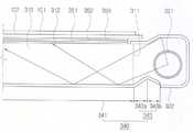
Translated fromKorean도 1은 본 발명의 제 1 실시예에 따른 액정표시장치의 분해 사시도,1 is an exploded perspective view of a liquid crystal display according to a first embodiment of the present invention;
도 2는 본 발명의 제 1 실시예에 따른 액정표시장치의 단면도,2 is a cross-sectional view of a liquid crystal display device according to a first embodiment of the present invention;
도 3은 본 발명의 제 2 실시예에 따른 액정표시장치의 단면도이다.3 is a cross-sectional view of a liquid crystal display device according to a second embodiment of the present invention.
* 도면의 주요 부분에 대한 부호의 설명 *Explanation of symbols on the main parts of the drawings
100 : 액정패널 310 : 도광판100: liquid crystal panel 310: light guide plate
320 : 광원부 321 : 광원320: light source unit 321: light source
322 : 광원커버 340 : 반사시트322: light source cover 340: reflective sheet
341 : 주반사부 343 : 돌출반사부341: main reflecting portion 343: projecting reflecting portion
343a : 제 1경사부 343b : 제 2경사부343a: first
344 : 지지부344 support
본 발명은 액정표시장치에 관한 것으로서, 보다 상세하게는 광원에 인접한 영역에서 발생하는 휘선이 감소되는 액정표시장치에 관한 것이다.The present invention relates to a liquid crystal display device, and more particularly, to a liquid crystal display device in which bright lines generated in an area adjacent to a light source are reduced.
최근 종래의 CRT를 대신하여 액정표시장치(LCD), PDP(plasma display panel, OLED(organic light emitting diode) 등의 평판표시장치가 많이 개발되고 있다. Recently, a flat panel display such as a liquid crystal display (LCD), a plasma display panel (PDP), or an organic light emitting diode (OLED) has been developed in place of the conventional CRT.
이 중 액정표시장치는 박막트랜지스터 기판, 컬러필터 기판 그리고 양 기판 사이에 액정이 주입되어 형성된 액정층으로 이루어진 액정패널을 포함한다. 액정표시장치는 비발광소자이기 때문에 박막트랜지스터 기판의 후면에는 빛을 공급하기 위한 백라이트 유닛이 위치한다. 백라이트 유닛에서 조사된 빛은 액정의 배열상태에 따라 투과량이 조정된다. 액정패널과 백라이트 유닛은 샤시 내에 수용되어 있다.The liquid crystal display includes a liquid crystal panel including a thin film transistor substrate, a color filter substrate, and a liquid crystal layer formed by injecting liquid crystal between both substrates. Since the liquid crystal display is a non-light emitting device, a backlight unit for supplying light is disposed on the rear surface of the thin film transistor substrate. Light transmitted from the backlight unit is adjusted according to the arrangement of liquid crystals. The liquid crystal panel and the backlight unit are housed in the chassis.
상기 백라이트 유닛은 광원의 위치에 따라 직하형과 에지형으로 구분된다.The backlight unit is divided into a direct type and an edge type according to the position of the light source.
직하형은 액정표시장치의 크기가 대형화되면서 중점적으로 개발된 구조로, 액정패널의 하부면에 하나 이상의 광원을 배치시켜 액정패널에 전면적으로 빛을 공급하는 구조이다.The direct type is a structure mainly developed as the size of the liquid crystal display device is enlarged. The direct type has a structure in which at least one light source is disposed on the lower surface of the liquid crystal panel to supply light to the liquid crystal panel.
에지형은 도광판의 측면에 광원이 설치되는 구조로, 주로 랩탑형 및 데스크탑 컴퓨터와 같이 비교적 크기가 작은 액정표시장치에 적용된다. 이러한 에지형 백라이트 유닛은 냉음극 형광램프 등의 광원을 도광판의 측면에 배치하고 광학필름을 도광판과 액정패널 사이에 배치하는 방식이다. 여기서 도광판과 하부 샤시 사이에는 반사시트가 배치되어 액정패널의 반대방향으로 투과되어 누설되는 빛을 다시 도광판으로 반사 시킨다.The edge type is a structure in which a light source is installed on the side of the light guide plate, and is mainly applied to a relatively small liquid crystal display device such as a laptop type and a desktop computer. The edge type backlight unit is a method of disposing a light source such as a cold cathode fluorescent lamp on the side of the light guide plate, and an optical film between the light guide plate and the liquid crystal panel. In this case, a reflective sheet is disposed between the light guide plate and the lower chassis to reflect the light leaking through the opposite direction of the liquid crystal panel to the light guide plate.
하지만, 광원에 인접한 부분의 반사시트에서 반사된 빛은 도광판의 가장 자리를 통해 액정패널 방향으로 투과된다. 이렇게 투과된 빛은 광원의 인접한 부분에 휘선을 발생시키므로 액정패널의 휘도가 불균일 해지는 문제가 있다.However, the light reflected from the reflective sheet adjacent to the light source is transmitted toward the liquid crystal panel through the edge of the light guide plate. Since the transmitted light generates bright lines in adjacent portions of the light source, the luminance of the liquid crystal panel is uneven.
따라서, 본 발명의 목적은 광원에 인접한 영역에서의 휘선이 감소된 액정표시장치를 제공하는 것이다.Accordingly, it is an object of the present invention to provide a liquid crystal display device having reduced bright lines in a region adjacent to a light source.
상기의 목적은 화상을 형성하는 액정패널과 상기 액정패널의 후방에 마련되며 도광판과 상기 도광판의 적어도 일 측변을 따라 배치되어 있는 광원과 상기 도광판의 후방에 배치되는 주반사부와 상기 주반사부의 측부에서 상기 광원을 따라 전방으로 돌출된 돌출반사부를 가지는 반사시트를 포함하는 액정표시장치에 의해 달성된다.The above object is provided with a liquid crystal panel forming an image and a rear side of the liquid crystal panel, a light source disposed along at least one side of the light guide plate and the light guide plate, and a main reflection portion and a side portion of the main reflection portion disposed behind the light guide plate. Is achieved by a liquid crystal display including a reflective sheet having a protruding reflecting portion projecting forward along the light source.
상기 돌출반사부는 제1경사부과 제2경사부로 이루어진 산 형상의 단면형상을 갖는 것이 바람직하다.It is preferable that the protruding reflecting portion has a mountain-shaped cross-sectional shape consisting of a first inclined portion and a second inclined portion.
상기 제1경사부과 상기 제2경사부 사이는 예각으로 이루어질 수 있다.An acute angle may be formed between the first inclined portion and the second inclined portion.
상기 제 1경사부 하부에 마련되어, 상기 제 1경사부를 지지하는 지지부를 더 포함할 수 있다.It may further include a support portion provided below the first inclined portion to support the first inclined portion.
상기 광원은 냉음극 형광램프 및 외부 전극형 형광램프 중 어느 하나를 포함할 수 있다.The light source may include any one of a cold cathode fluorescent lamp and an external electrode fluorescent lamp.
상기 반사시트는 폴리에틸렌테레프탈레이트 및 폴리카보네이트 중 어느 하나로 이루어질 수 있다.The reflective sheet may be made of any one of polyethylene terephthalate and polycarbonate.
본 발명의 제 1실시예에 따른 액정표시장치를 도1 및 도 2를 참조하여 설명 하면 다음과 같다. 도1은 본 발명의 제1실시에에 따른 액정표시장치의 분해사시도이고, 도2는 그 단면도이다.A liquid crystal display according to a first embodiment of the present invention will be described with reference to FIGS. 1 and 2 as follows. 1 is an exploded perspective view of a liquid crystal display according to a first embodiment of the present invention, and FIG. 2 is a cross-sectional view thereof.
도시된 바와 같이, 액정표시장치(1)는 액정패널(100)과 백라이트유닛 (300)으로 구성된다.As shown, the liquid
액정패널(100)은 박막트랜지스터가 형성되어 있는 박막트랜지스터 기판(101)과 박막트랜지스터 기판(101)과 대면하고 있는 컬러필터 기판(102), 양 기판(101, 102)을 접합시키며 셀갭(cell gap)을 형성하는 실런트, 양 기판(101, 102)과 실런트 사이에 위치하는 액정층을 포함한다. 액정패널(100)은 액정층의 배열을 조정하여 화면을 형성하지만 비발광소자이기 때문에 배면에 위치한 광원(321)으로부터 빛을 공급 받아야 한다. 박막트랜지스터 기판(101)의 일측에는 구동신호 인가를 위한 구동부(140)가 마련되어 있다. 구동부(140)는 연성인쇄회로기판(FPC. 142), 연성 인쇄회로기판(142)에 장착되어 있는 구동칩(141), 연성인쇄회로기판(142)의 타측에 연결되어 있는 회로기판(PCB, 143)을 포함한다. 도시된 구동부(140)는 COF(chip on film) 방식을 나타낸 것이며, TCP(tape carrier package), COG(chip on glass) 등 공지의 다른 방식도 가능하다. 또한 구동부 (140)가 배선형성과정에서 박막트랜지스터 기판(101)에 형성되는 것도 가능하다.The
액정패널(100)의 배면에 위치하는 백라이트 유닛(300)은 액정패널(100)의 배면에 평행하게 배치되는 광학시트류(350)와, 빛을 방출하는 광원부(320)와, 측변에 광원부(320)가 평행하게 위치하고 있는 도광판(310) 및 도광판(310) 배면에 마련된 반사시트(340)를 포함한다.The
광학시트류(350)는 액정패널(100)의 배면에 위치하는 보호시트(353), 프리즘 시트(352) 및 확산시트(351)를 포함한다. 확산시트(351)는 베이스판과 베이스판에 형성된 구슬 모양의 코팅층으로 이루어져 있다. 확산시트(351)는 광원(321)으로부터의 빛을 확산시켜 액정패널(100)로 공급하는 역할을 한다. 확산시트(351)는 2장 또는 3장을 겹쳐서 사용할 수 있다. 프리즘 시트(352)는 상부면에 삼각기둥 모양의 프리즘이 일정한 배열을 갖고 형성되어 있다. 프리즘 시트(352)는 확산시트(351)에서 확산된 빛을 상부의 액정패널(100)의 평면에 수직한 방향으로 집광하는 역할을 수행한다. 프리즘 시트(352)는 통상 2장이 사용되며 각 프리즘 시트(352)에 형성된 마이크로 프리즘은 소정을 각도를 이루고 있다. 프리즘 시트(352)를 통과한 빛은 거의 대부분 수직하게 진행되어 균일한 휘도 분포를 제공하게 된다. 가장 상부에 위치하는 보호시트(353)는 스크래치에 약한 프리즘 시트(352)를 보호한다.The
광원부(320)는 도광판(310)의 한 측변을 따라 마련되며 광원(321)과 광원 커버(322)를 포함한다.The
광원(321)은 냉음극형광램프(Cold Cathode Fluorescent Lamp; CCFL) 또는 외부전극 형광램프(External Electrode Fluorescent Lamp; EEFL) 로 마련될 수 있다. 광원(321)은 도광판(310)의 마주보는 양변측에 하나씩 마련되어 있다. 다른 실시예에 따르면, 일 측에 마련되는 광원(321)은 복수로 마련되어 상하로 상호 평행하게 위치할 수도 있으며, 액정패널(100) 배면의 적어도 일 측변에 마련되기만 하면 광원(321)이 마련되는 측 변의 개수도 변형 가능하다. 또한, 에지 방식으로 배열된다면 광원(321)은 LED일 수도 있다.The
광원 커버(322)는 광원(321)에서 발생된 빛을 도광판(310)방향으로 반사시키는 역할을 한다. 광원 커버(322)는 반사율이 좋은 알루미늄판 등으로 제조될 수 있으며, 광원(321)을 향하는 면에는 은 코팅이 되어 있을 수 있다.The
도광판(310)은 광원(321)으로부터 빛을 받는 입사면(311)과, 입사면(311)과 직각을 이루며 액정패널(100)에 대해 평행한 출사면(312)과, 광원(321)에서 입사면(311)으로 조사된 빛이 출사면(312)으로 진행되도록 패턴이 형성된 배면을 갖는다. 도광판(310)은 도광판(310)의 일측 측변을 따라, 즉 입사면(311)에 인접하게 배치된 광원(321)에서 입사면(311)으로 조사된 빛을 평면광으로 바꾸고, 이를 출사면(312)을 통해 액정패널(100)로 균일하게 전달한다. 이러한 도광판(310)의 재질로는 강도가 높아 쉽게 변형되거나 깨지지 않으며 투과율이 좋은 PMMA(Polymethylmethacrylate)가 사용된다.The
반사시트(340)는 도광판(310)의 배면에 배치되어 도광판(310)으로 빛을 보내는 주반사부(341)와 상기 광원(321)에 인접한 주반사부(341)의 변에서 상기 도광판(310) 방향으로 돌출되어 있는 돌출반사부(343)로 이루어졌다.The
돌출반사부(343)는 도광판(310) 방향으로 접힌 제 1경사부(343a) 및 상기 제 1경사부(343a)로부터 상기 도광판(310)의 반대 방향으로 접힌 제 2경사부(343b)를 포함한다. 이러한 반사시트(340)의 재질은 폴리 에틸렌테레프탈레이트나 폴리카보네이트를 포함하여 이루어질 수 있다.The protruding reflecting
도광판(310) 하부에 위치하는 반사시트(340)는 도광판(310)을 통과한 후 액정패널(100)의 반대 방향으로 투과되는 빛을 다시 도광판(310)으로 반사 시킴으로 써 빛의 손실을 줄이고 도광판(310)에서 액정패널(100) 방향으로 투과되는 빛의 균일도를 향상시키는데 기여한다.The
종래의 경우, 광원(321)에 인접한 부분의 반사시트(340) 영역에서 반사된 빛은 도광판(310)의 가장 자리에서 투과되어 액정패널(100) 방향으로 향하게 된다. 이에 빛은 도광판(310) 전체면에서 고르게 출사되지 못한다.In the related art, the light reflected from the area of the
본 발명의 일 실시예에 따른 반사시트(340)의 경우 돌출반사부(343)의 제 1경사부(343a)는 주반사부(341)와 둔각을 이루며 제 2경사부(343b)는 제 1경사부(343a)와 예각을 이룬다. 이에 따라 광원(321)으로부터 방출된 빛이 광원(321)에 인접한 반사시트(340)의 변에서 반사되지 않게 되고 도광판(310)의 가장 자리로 투과되는 것이 방지된다.In the
시간이 지남에 따라 제 1경사부(343a)는 도광판(310)의 반대 방향으로 내려오게 되지만 도광판(310)의 반대 방향으로 접힌 제 2경사부(343b)에 의해 완전히 펴지지는 것이 방지된다. 즉 광원(321)에 인접한 반사시트(340)의 변이 소정의 높이만큼 들어올려진 상태가 유지되어 광원에 인접한 반사시트(340)에서의 반사가 방지되므로 도광판(310)의 출사면(312) 전체에 걸쳐 빛이 균일하게 방출된다.As time passes, the first
일반적으로 백라이트유닛(300)은 몰드 프레임(200) 및 하부 샤시(160)에 의해 고정되며 하부 샤시(160)는 상부 샤시(150)와 결합되며, 몰드 프레임(200)은 액정패널(100)의 연부를 따라 대략 사각의 형상으로 마련되어 액정패널(100)을 백라이트유닛(300)에 대해 이격시켜 지지하는 역할을 한다.In general, the
도 3은 본 발명의 제 2실시예에 따른 반사시트(340)를 나타내는 도면으로, 반사시트(340)를 제외하고 도 1의 제 1실시예와 동일한 구성요소를 가진다.3 is a view showing a
본 발명에 따른 반사시트(340)는 도광판(310) 배면에 배치되며 도광판(310) 으로 빛을 보내는 주반사부(341)와 광원(321)에 인접한 반사시트(340)의 변에서 도광판(310) 방향으로 돌출되어 있는 돌출반사부(343)로 이루어진다.Reflecting
돌출반사부(343)는 도광판(310)의 방향으로 접힌 제 1경사부(343a)와 상기 제 1경사부(343a)로부터 도광판(310)의 반대 방향으로 접힌 제 2경사부(343b) 및 제 1경사부(343a)의 배면에 삽입된 지지부(344)로 이루어진다.The protruding reflecting
제 1경사부(343a)는 주반사부(341)와 둔각을 이루며 제 2경사부(343b)는 제 1경사부(343a)와 예각을 이룬다. 또한 지지부(344)는 제 1경사부(343a)의 배면에 접하여 마련되어 있다.The first
도광판(310) 방향으로 접힌 제 1경사부(343a)에 의해 광원(321)에 인접한 반사시트(340)의 변에서 반사가 되는 것이 방지되나, 시간이 지남에 따라 제 1경사부(343a)는 도광판(310)의 반대 방향으로 내려오게 된다.하지만 도광판(310)의 반대 방향으로 접힌 제 2경사부(343b)가 1경사부(343a)를 지지하여 완전히 펴지지는 것을 지연한다. 즉 제 2 경사부(343b)에 의해 광원(321)에 인접한 반사시트(340)의 변이 소정의 높이만큼 들어올려진 상태가 유지된다.Although the reflection is prevented from the side of the
하지만 제 1경사부(343a) 및 제 2경사부(343b)가 시간이 지남에 따라 원래의 상태인 도광판(310)의 반대 방향으로 내려오게 되는데 이를 방지하기 위해 제 1경사부(343a) 배면에는 지지부를 마련한다.However, the first
지지부(344)는 도광판(310) 방향으로 돌출된 반사시트(340)의 형상을 유지시 킬 만큼의 강도를 가지며 제 1경사부(343a) 배면에 접하여 삽입되므로 광원(321)에 인접한 반사시트(340)의 변이 들어올려진 상태로 유지된다.The
따라서 광원(321)에 인접한 반사시트(340)의 변에서의 반사가 방지되므로 도광판(310)의 출사면(312) 전체에 걸쳐 빛이 균일하게 방출된다.Accordingly, since reflection from the side of the
반사시트(340)의 형상은 본 발명의 실시예에서와 같이 광원(321)에 인접한 반사시트(340)의 변이 도광판(310) 방향으로 접히는 제 1경사부(343a)와 상기 제 1경사부로부터 도광판(310)의 반대 방향으로 접히는 제 2경사부(343b)를 갖는 구조에만 한정되지 않고, 광원(321)에 인접한 반사시트(340)의 변이 들려 있는 상태로 형성된 모든 구조에 적용 가능하다. The shape of the
비록 본 발명의 몇몇 실시예들이 도시되고 설명되었지만, 본 발명이 속하는 기술분야의 통상의 지식을 가진 당업자라면 본 발명의 원칙이나 정신에서 벗어나지 않으면서 광원(321)에 인접한 반사시트(340)의 변에서의 반사가 방지되도록 도광판 방향으로 돌출되어 휘도를 향상시킨 본 실시예를 변형할 수 있음을 알 수 있을 것이다. 발명의 범위는 첨부된 청구항과 그 균등물에 의해 정해질 것이다.Although some embodiments of the invention have been shown and described, one of ordinary skill in the art will appreciate that the sides of the
이상 설명한 바와 같이, 본 발명에 따르면 광원에 인접한 영역에서의 휘선이 감소된 액정표시장치가 제공된다.As described above, according to the present invention, there is provided a liquid crystal display device having reduced bright lines in an area adjacent to a light source.
Claims (6)
Translated fromKoreanPriority Applications (1)
| Application Number | Priority Date | Filing Date | Title |
|---|---|---|---|
| KR1020050064272AKR20070009185A (en) | 2005-07-15 | 2005-07-15 | LCD Display |
Applications Claiming Priority (1)
| Application Number | Priority Date | Filing Date | Title |
|---|---|---|---|
| KR1020050064272AKR20070009185A (en) | 2005-07-15 | 2005-07-15 | LCD Display |
Publications (1)
| Publication Number | Publication Date |
|---|---|
| KR20070009185Atrue KR20070009185A (en) | 2007-01-18 |
Family
ID=38011052
Family Applications (1)
| Application Number | Title | Priority Date | Filing Date |
|---|---|---|---|
| KR1020050064272AWithdrawnKR20070009185A (en) | 2005-07-15 | 2005-07-15 | LCD Display |
Country Status (1)
| Country | Link |
|---|---|
| KR (1) | KR20070009185A (en) |
Cited By (1)
| Publication number | Priority date | Publication date | Assignee | Title |
|---|---|---|---|---|
| KR101308007B1 (en)* | 2007-01-31 | 2013-09-12 | 엘지디스플레이 주식회사 | Liquid Crystal Display |
- 2005
- 2005-07-15KRKR1020050064272Apatent/KR20070009185A/ennot_activeWithdrawn
Cited By (2)
| Publication number | Priority date | Publication date | Assignee | Title |
|---|---|---|---|---|
| KR101308007B1 (en)* | 2007-01-31 | 2013-09-12 | 엘지디스플레이 주식회사 | Liquid Crystal Display |
| US8593588B2 (en) | 2007-01-31 | 2013-11-26 | Lg Display Co., Ltd. | Liquid crystal display device with uniform luminance |
Similar Documents
| Publication | Publication Date | Title |
|---|---|---|
| US7728923B2 (en) | Backlight unit and display device having the same | |
| KR101189080B1 (en) | Reflecting plate and liquid crystal display device having the same | |
| KR101429176B1 (en) | Back-light assembly and display device having the same | |
| CN101201508B (en) | Back-light unit and liquid crystal display having the same | |
| KR20060104078A (en) | Backlight unit and liquid crystal display including the same | |
| US8698972B2 (en) | Liquid crystal display device | |
| KR20070001362A (en) | LCD Display | |
| KR20070014861A (en) | Backlight assembly and liquid crystal display including the same | |
| KR20070103944A (en) | LCD Display | |
| KR20070009185A (en) | LCD Display | |
| KR100698061B1 (en) | Direct type backlight unit | |
| KR20070023249A (en) | LCD Display | |
| KR20070010408A (en) | LCD Display | |
| KR20070077610A (en) | LCD Display | |
| KR20060134742A (en) | LCD Display | |
| KR20060081790A (en) | Reflector and liquid crystal display including the same | |
| KR20060136051A (en) | Liquid crystal display device | |
| KR20070000081A (en) | Liquid crystal display device | |
| KR20070053392A (en) | LCD Display | |
| KR20080035837A (en) | Backlight unit and liquid crystal display including the same | |
| KR20070055884A (en) | LCD and its manufacturing method | |
| KR20070082172A (en) | LCD Display | |
| KR20060113175A (en) | LCD Display | |
| KR20060130309A (en) | Liqauid crystal display | |
| KR20080032833A (en) | LCD Display |
Legal Events
| Date | Code | Title | Description |
|---|---|---|---|
| PA0109 | Patent application | Patent event code:PA01091R01D Comment text:Patent Application Patent event date:20050715 | |
| PG1501 | Laying open of application | ||
| PC1203 | Withdrawal of no request for examination | ||
| WITN | Application deemed withdrawn, e.g. because no request for examination was filed or no examination fee was paid |