KR20070002540A - Water Supply Method of Commercial Washing Equipment - Google Patents
Water Supply Method of Commercial Washing EquipmentDownload PDFInfo
- Publication number
- KR20070002540A KR20070002540AKR1020050058120AKR20050058120AKR20070002540AKR 20070002540 AKR20070002540 AKR 20070002540AKR 1020050058120 AKR1020050058120 AKR 1020050058120AKR 20050058120 AKR20050058120 AKR 20050058120AKR 20070002540 AKR20070002540 AKR 20070002540A
- Authority
- KR
- South Korea
- Prior art keywords
- water
- water supply
- detergent
- commercial
- bleach
- Prior art date
- Legal status (The legal status is an assumption and is not a legal conclusion. Google has not performed a legal analysis and makes no representation as to the accuracy of the status listed.)
- Granted
Links
Images


Classifications
- D—TEXTILES; PAPER
- D06—TREATMENT OF TEXTILES OR THE LIKE; LAUNDERING; FLEXIBLE MATERIALS NOT OTHERWISE PROVIDED FOR
- D06F—LAUNDERING, DRYING, IRONING, PRESSING OR FOLDING TEXTILE ARTICLES
- D06F33/00—Control of operations performed in washing machines or washer-dryers
- D06F33/30—Control of washing machines characterised by the purpose or target of the control
- D06F33/32—Control of operational steps, e.g. optimisation or improvement of operational steps depending on the condition of the laundry
- D06F33/34—Control of operational steps, e.g. optimisation or improvement of operational steps depending on the condition of the laundry of water filling
- D—TEXTILES; PAPER
- D06—TREATMENT OF TEXTILES OR THE LIKE; LAUNDERING; FLEXIBLE MATERIALS NOT OTHERWISE PROVIDED FOR
- D06F—LAUNDERING, DRYING, IRONING, PRESSING OR FOLDING TEXTILE ARTICLES
- D06F39/00—Details of washing machines not specific to a single type of machines covered by groups D06F9/00 - D06F27/00
- D06F39/08—Liquid supply or discharge arrangements
- D06F39/087—Water level measuring or regulating devices
- D—TEXTILES; PAPER
- D06—TREATMENT OF TEXTILES OR THE LIKE; LAUNDERING; FLEXIBLE MATERIALS NOT OTHERWISE PROVIDED FOR
- D06F—LAUNDERING, DRYING, IRONING, PRESSING OR FOLDING TEXTILE ARTICLES
- D06F39/00—Details of washing machines not specific to a single type of machines covered by groups D06F9/00 - D06F27/00
- D06F39/08—Liquid supply or discharge arrangements
- D06F39/088—Liquid supply arrangements
- D—TEXTILES; PAPER
- D06—TREATMENT OF TEXTILES OR THE LIKE; LAUNDERING; FLEXIBLE MATERIALS NOT OTHERWISE PROVIDED FOR
- D06F—LAUNDERING, DRYING, IRONING, PRESSING OR FOLDING TEXTILE ARTICLES
- D06F95/00—Laundry systems or arrangements of apparatus or machines; Mobile laundries
- D—TEXTILES; PAPER
- D06—TREATMENT OF TEXTILES OR THE LIKE; LAUNDERING; FLEXIBLE MATERIALS NOT OTHERWISE PROVIDED FOR
- D06F—LAUNDERING, DRYING, IRONING, PRESSING OR FOLDING TEXTILE ARTICLES
- D06F2101/00—User input for the control of domestic laundry washing machines, washer-dryers or laundry dryers
- D06F2101/12—Washing temperature
- D—TEXTILES; PAPER
- D06—TREATMENT OF TEXTILES OR THE LIKE; LAUNDERING; FLEXIBLE MATERIALS NOT OTHERWISE PROVIDED FOR
- D06F—LAUNDERING, DRYING, IRONING, PRESSING OR FOLDING TEXTILE ARTICLES
- D06F2103/00—Parameters monitored or detected for the control of domestic laundry washing machines, washer-dryers or laundry dryers
- D06F2103/18—Washing liquid level
- D—TEXTILES; PAPER
- D06—TREATMENT OF TEXTILES OR THE LIKE; LAUNDERING; FLEXIBLE MATERIALS NOT OTHERWISE PROVIDED FOR
- D06F—LAUNDERING, DRYING, IRONING, PRESSING OR FOLDING TEXTILE ARTICLES
- D06F2105/00—Systems or parameters controlled or affected by the control systems of washing machines, washer-dryers or laundry dryers
- D06F2105/02—Water supply
- D06F2105/04—Water supply from separate hot and cold water inlets
Landscapes
- Engineering & Computer Science (AREA)
- Textile Engineering (AREA)
- Detail Structures Of Washing Machines And Dryers (AREA)
Abstract
Translated fromKoreanDescription
Translated fromKorean도 1은 본 발명의 상업용 세정장치가 도시된 사시도,1 is a perspective view showing a commercial cleaning device of the present invention,
도 2는 본 발명에 따른 상업용 배기식 건조기의 내부 구성이 도시된 단면도,Figure 2 is a cross-sectional view showing the internal configuration of a commercial exhaust dryer according to the present invention,
도 3은 본 발명에 따른 상업용 배기식 건조기의 주요부가 도시된 분해 사시도,Figure 3 is an exploded perspective view showing the main part of a commercial exhaust dryer according to the present invention,
도 4는 본 발명에 따른 상업용 배기식 건조기가 도시된 분해 사시도,4 is an exploded perspective view illustrating a commercial exhaust dryer according to the present invention;
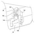
도 5는 본 발명에 따른 상업용 배기식 건조기의 제 1,2 브래킷이 도시된 사시도,5 is a perspective view of the first and second brackets of the commercial exhaust dryer according to the present invention,
도 6a와 도 6b 및 도 6c는 본 발명에 따른 상업용 배기식 건조기의 제 1,2 브래킷이 도시된 작동 상태도,6a and 6b and 6c is an operating state diagram showing the first and second brackets of a commercial exhaust dryer according to the present invention,
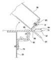
도 7은 본 발명에 따른 상업용 배기식 건조기의 탑 플레이트에 구비된 잠금 장치가 도시된 사시도, 7 is a perspective view showing a locking device provided on the top plate of a commercial exhaust dryer according to the present invention,
도 8은 본 발명에 따른 상업용 드럼 세탁기의 내부 구성이 도시된 단면도,8 is a cross-sectional view showing the internal configuration of a commercial drum washing machine according to the present invention,
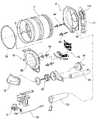
도 9는 본 발명에 따른 상업용 드럼 세탁기가 도시된 분해 사시도,9 is an exploded perspective view showing a commercial drum washing machine according to the present invention;
도 10은 본 발명에 따른 상업용 세정장치의 급수방법이 도시된 순서도,10 is a flow chart illustrating a water supply method of a commercial cleaning device according to the present invention;
도 11은 본 발명에 따른 상업용 드럼 세탁기의 세제공급기구가 도시된 분해 사시도,11 is an exploded perspective view showing a detergent supply mechanism of a commercial drum washing machine according to the present invention;
도 12는 도 11의 A-A선에 따른 단면이 도시된 도,12 is a cross-sectional view taken along the line A-A of FIG.
도 13은 도 11의 B-B선에 따른 단면이 도시된 도,13 is a cross-sectional view taken along the line B-B of FIG.
도 14는 본 발명에 따른 세제공급기구의 세제박스 본체와 세제박스 캡이 도시된 평면도,14 is a plan view showing a detergent box body and a detergent box cap of the detergent supply mechanism according to the present invention;
도 15는 도 14의 C-C선에 따른 단면이 도시된 도,15 is a cross-sectional view taken along the line C-C of FIG. 14;
도 16은 도 14의 D-D선에 따른 단면이 도시된 도,16 is a cross-sectional view taken along the line D-D of FIG. 14;
도 17은 본 발명에 따른 세제공급기구의 세제박스 본체와 세제박스 캡이 분해되어 도시된 도,17 is an exploded view of the detergent box body and the detergent box cap of the detergent supply mechanism according to the present invention;
도 18은 본 발명에 따른 세제공급기구의 세제박스 본체 하부가 도시된 사시도,18 is a perspective view of the lower portion of the detergent box body of the detergent supply mechanism according to the present invention;
<도면의 주요 부분에 관한 부호의 설명><Explanation of symbols on main parts of the drawings>
200: 상업용 세탁기200: commercial washing machine
202: 캐비닛204: 스프링202: cabinet 204: spring
205: 댐퍼206: 터브205: damper 206: tub
207: 수공208: 드럼207: handmade 208: drum
210: 리프터212: 모터210: lifter 212: motor
214: 캐비닛 커버216: 탑 플레이트214: cabinet cover 216: top plate
218: 베이스220: 도어218: base 220: door
222: 컨트롤 패널224: 지지 프레임222: control panel 224: support frame
230: 급수장치232: 급수호스230: water supply device 232: water supply hose
234: 급수밸브236: 급수 밸로우즈234: water supply valve 236: water supply bellows
240: 배수장치242: 배수호스240: drainage 242: drainage hose
244: 배수펌프246: 배수 밸로우즈244: drain pump 246: drain bellows
250: 세제공급기구252: 세제박스 하우징250: detergent supply mechanism 252: detergent box housing
253: 배수구254: 세제박스253: drain 254: detergent box
256: 디스펜서 커버260: 세제박스 본체256: dispenser cover 260: detergent box body
262: 세제 수용부264: 전면부262: detergent receiving portion 264: front portion
265: 우측벽부266: 좌측벽부265: right wall portion 266: left wall portion
268: 구획 측벽부270: 전면 패널268: partition side wall portion 270: front panel
272: 손잡이274: 체결볼트272: handle 274: fastening bolt
280: 세제박스 캡281: 제 1 끼움돌기280: detergent box cap 281: first fitting protrusion
282: 밀착부283: 표백제 투입구282: contact portion 283: bleach inlet
284: 유연제 투입구285: 표백제 사이폰 캡284
286: 유연제 사이폰 캡287: 표백제 보조 투입구286 softener siphon
288: 유연제 보조 투입구290: 상측 구획리브288: softener auxiliary inlet 290: upper compartment rib
292: 제 1 고정리브294: 제 2 고정리브292: first fixed rib 294: second fixed rib
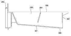
296: 제 3 고정리브300: 제 1 세제 수용부296: 3rd fixed rib 300: 1st detergent accommodating part
302: 차단벽304: 세제량 설정벽302: barrier wall 304: detergent amount setting wall
306: 배출홀부310: 제 2 세제수용부306: discharge hole 310: second detergent holding portion
311: 표백제 수용부312: 유연제 수용부311: bleach receiver 312: softener receiver
313: 표백제 사이폰 관313: bleach siphon tube
314: 유연제 사이폰 관316: 하측 구획리브314: softener siphon tube 316: lower compartment rib
317: 후벽부318: 차폐벽317: rear wall portion 318: shielding wall
319: 안착부320: 탈거방지수단319: seating unit 320: stripping prevention means
322: 패널부324: 돌기부322: panel portion 324: projection portion
326: 탄성부327: 수직 리브326: elastic portion 327: vertical rib
328: 경사 리브330: 세제 급수유로328: inclined rib 330: detergent supply oil
332: 표백제 급수유로334: 유연제 급수유로332: bleach feed oil 334: softener feed oil
340: 제 1 급수홀342: 제 2 급수홀340: first water supply hole 342: second water supply hole
344: 표백제 급수홀346: 유연제 급수홀344: bleach water supply hole 346: softener water supply hole
348: 수직 홀부349: 보스부348: vertical hole portion 349: boss portion
S: 세제박스의 인출시 세제 투입 공간S: Detergent input space when taking out the detergent box
S1: 표백제 투입부S2: 유연제 투입부S1: Bleach input S2: Softener input
본 발명은 상업용 세정장치의 급수방법에 관한 것으로서, 특히 급수시간이 단축되고, 세정물의 세탁 코스에 따라 온수의 사용량이 최소화될 수 있는 상업용 세정장치의 급수방법에 관한 것이다.The present invention relates to a water supply method of a commercial cleaning device, and more particularly, to a water supply method of a commercial cleaning device which can shorten the water supply time and minimize the use of hot water according to the washing course of the cleaning material.
일반적으로 세정 장치는 의복, 침구 등(이하, 세정물이라 칭함)에 묻은 오염을 떼어 내도록 세탁, 헹굼, 탈수, 건조 등의 과정을 통해 세정물을 세정하는 장치로서, 세탁기 및 건조기 등이 대표적이다.In general, the cleaning device is a device that cleans the cleaning material by washing, rinsing, dehydrating, drying, etc. so as to remove contaminants on clothes, bedding, etc. (hereinafter, referred to as cleaning material). .
상기와 같은 세정장치는 사용 목적에 따라 가정용 세정 장치와 상업용 세정 장치로 구분되는 바, 상기 가정용 세정 장치는 각 가정에 비치되어 가정의 구성원에 의해 발생되는 세정물을 세정하는 데 이용되고, 상기 상업용 세정 장치는 점포에 비치되어 세정물을 세정하려는 고객에게 소정의 사용료를 받고 사용을 임대해주는 데 이용된다.The cleaning apparatus as described above is divided into household cleaning apparatus and commercial cleaning apparatus according to the purpose of use, and the household cleaning apparatus is provided in each household and used to clean the cleaning materials generated by members of the household. The cleaning apparatus is provided at a store and used to rent a use for a predetermined fee to a customer who wants to clean the cleaning product.
이러한 상업용 세정 장치는 사업자의 수익을 목적으로 공공의 장소에 설치되어 고객에 의해 사용되는 것으로서, 상기 가정용 세정 장치와 비교하여 수익성, 안전성, 정비성 등이 우수하도록 설계 및 제작된다.The commercial cleaning device is installed in a public place and used by a customer for the purpose of profit of a business operator, and is designed and manufactured to be more profitable, safer, and maintainable than the household cleaning device.
즉, 상기 상업용 세정 장치는 요금을 처리하기 위한 장치 및 그 장치의 제어 알고리즘이 추가적으로 필요할 뿐만 아니라, 사업자의 수익이 극대화될 수 있는 별도의 세탁 알고리즘도 필요하게 된다.That is, the commercial cleaning device requires not only an apparatus for processing a fee and a control algorithm of the apparatus, but also a separate washing algorithm for maximizing the profit of the operator.
또한, 상기 상업용 세정장치는 고객에 의해 제품이 파손되거나 또는 부품이 분실되는 것을 방지함과 아울러 정비시 작업이 매우 간편하고 신속하게 이루어질 수 있는 구조로 제작되어야만 한다.In addition, the commercial cleaning device should be made of a structure that can prevent the product from being damaged or lost parts by the customer, as well as very easy and quick work during maintenance.
한편, 종래의 상업용 세정장치 중 상업용 세탁기에는 세정물에 온수 또는 냉수를 공급하는 급수장치와, 상기 급수장치의 유로 상에 설치되어 분말세제와 표백제 및 유연제 등을 세정물에 공급하는 세제공급기구가 구비된다.Meanwhile, among commercial washing machines of the related art, commercial washing machines include a water supply device for supplying hot water or cold water to the cleaning product, and a detergent supply mechanism installed on the flow path of the water supply device to supply powder detergent, bleach, and softener to the cleaning product. It is provided.
상기와 같은 급수장치에는 온수의 공급을 단속하는 온수밸브와, 냉수의 공급을 단속하는 냉수밸브가 포함되고, 상기 세제공급기구는 상기 급수장치에 의해 급수되는 물과 함께 분말세제와 표백제 및 유연제 등을 세정물에 공급하게 된다.The water supply device includes a hot water valve for regulating the supply of hot water, and a cold water valve for regulating the supply of cold water, and the detergent supply mechanism includes powder detergent, bleach, and softener together with water supplied by the water supply device. Is supplied to the washings.
그러나, 종래 기술에 따른 상업용 세탁기의 급수방법은 상기 세정물의 포량을 감지하여 상기 급수장치의 급수수위가 설정되므로, 상기 상업용 세탁기에 의해 세정물을 세탁하는 동작과는 무관한 포량 감지 과정으로 인해 급수시간이 전체적으로 증대되는 문제점이 있다.However, in the water supply method of the commercial washing machine according to the prior art, since the water supply level of the water supply device is set by detecting the quantity of the cleaning water, the water supply is due to the quantity detection process irrelevant to the operation of washing the cleaning water by the commercial washing machine. There is a problem that the time is increased as a whole.
즉, 상기 상업용 세탁기는 세탁 시간이 단축되어 상기 상업용 세탁기의 이용 고객이 증가될수록 업자의 수익성이 크게 향상된다. 따라서, 상기 세정물의 세탁시 포량 감지를 실시하게 되면 상기 세정물을 세탁하기 위한 최적의 급수수위가 설정되나, 상기 포량 감지는 세정물을 세탁하는 동작은 아니기 때문에 업자의 수익성 측면에서는 상기 포량 감지가 불리하게 작용된다.That is, the commercial washing machine has a shorter washing time, and as the number of customers using the commercial washing machine increases, the profitability of the manufacturer is greatly improved. Therefore, if the detection of the amount of laundry to wash the washing water is set to the optimum level of water for washing the washing water, but the detection of the quantity is not an operation to wash the washing water, so in terms of profitability of the contractor, It is disadvantageous.
또한, 상기 상업용 세탁기는 세정물의 종류에 따라 고객에 의해 세탁 코스가 선택되고 상기 세정물은 선택된 세탁 코스에 따라 온수세탁 또는 냉수세탁 중 어느 한 방법으로 세탁이 이루어지는 바, 상기 세정물의 온수 세탁시에는 세정물의 종류와 상관없이 온수가 설정수위까지 연속 급수되므로 온수의 낭비가 심화되고, 상기 세정물의 종류에 따라서는 급수된 온수에 의해 열 손상과 변형이 발생되는 문제점이 있다.In addition, the commercial washing machine is selected by the customer according to the type of washing the washing course, the washing is performed by any method of hot water washing or cold water washing according to the selected washing course, when washing the hot water Regardless of the type of cleaning material, since hot water is continuously supplied to the set water level, waste of hot water is intensified, and thermal damage and deformation are caused by the supplied hot water depending on the type of the cleaning material.
즉, 상기 상업용 세탁기는 냉수세탁과 온수세탁시 냉수밸브와 온수밸브 중 어느 하나만 개방되어 냉수 또는 온수만이 급수되므로, 상기 상업용 세탁기는 세정물에 중간 온도의 물이 급수될 수 없기 때문에 중온의 온수세탁은 불가능하게 된다. 따라서, 상기 중온의 온수에서 세탁이 이루어져야만 하는 세정물은 온수 세탁시 상기 온수밸브로 급수되는 고온의 온수에 의해 열 손상이나 변형이 발생된다.That is, the commercial washing machine is only cold water or hot water is supplied when only one of the cold water valve and the hot water valve is opened during cold water washing and hot water washing, so the commercial washing machine is not able to supply medium temperature water to the washing water, so Washing becomes impossible. Therefore, the washing water to be washed in the warm water of the medium temperature is heat damage or deformation is caused by the high temperature hot water supplied to the hot water valve when washing the hot water.
본 발명은 상기한 문제점을 해결하기 위하여 창출된 것으로서, 본 발명의 목적은 상업용 세정장치의 세탁시 포량 감지 구간이 생략되어 상업용 세정장치의 급수시간이 단축되고, 상기 상업용 세정장치의 세탁 코스에 따라 온수와 냉수의 급수방법이 최적화되어 온수의 사용량 및 세정물의 세탁성능이 최적화될 수 있는 상업용 세정장치의 급수방법을 제공하는데 있다.The present invention was created in order to solve the above problems, an object of the present invention is to omit the detection of the amount of water during the washing of the commercial cleaning device is shortened the water supply time of the commercial cleaning device, according to the washing course of the commercial cleaning device The water supply method of hot water and cold water is optimized to provide a water supply method of a commercial cleaning device that can optimize the amount of hot water and washing performance of the cleaning water.
상기한 과제를 실현하기 위한 본 발명에 따른 상업용 세정장치의 급수방법은 냉수가 제 1 설정시간까지 간헐적으로 급수되는 제 1 급수단계와, 세정물의 세탁 코스에 따라 냉수 또는 온수가 설정수위까지 연속적으로 급수되는 제 2 급수단계와, 상기 제 2 급수단계의 급수수위가 설정수위에 도달되면 제 2 설정시간동안 급수가 정지된 후 급수수위가 재 감지되는 수위감지단계와, 상기 수위감지단계에서 감지된 수위와 설정수위의 차이만큼 냉수 또는 온수가 재 급수되는 제 3 급수단계로 구성된 것을 특징으로 한다.The water supply method of the commercial cleaning device according to the present invention for realizing the above problems is the first water supply step in which the cold water is intermittently supplied to the first set time, and the cold water or hot water continuously up to the set water level according to the washing course of the cleaning water. A second water supply step of supplying water and a water level detection step of re-detecting the water supply level after the water supply is stopped for a second set time when the water supply level of the second water supply step reaches a set water level; And a third water supply stage in which cold water or hot water is rewatered by a difference between the water level and the set water level.
상기 설정수위는 상업용 세정장치의 최대 급수수위이거나, 또는 사용자에 의해 설정된 수위인 것을 특징으로 한다.The set water level is the maximum water level of the commercial cleaning device, or characterized in that the level set by the user.
여기서, 상기 상업용 세정장치의 세탁 코스가 고온의 온수세탁이면, 상기 제 2 급수단계와 제 3 급수단계에서는 온수밸브가 개방됨과 아울러 냉수밸브가 밀폐된다.Here, when the washing course of the commercial cleaning apparatus is hot water washing at a high temperature, the hot water valve is opened and the cold water valve is closed in the second water supply step and the third water supply step.
그리고, 상기 상업용 세정장치의 세탁 코스가 중온의 온수세탁이면, 상기 제 2 급수단계에서는 온수밸브와 냉수밸브가 개방되고, 상기 제 3 급수단계에서는 온수밸브가 밀폐됨과 아울러 냉수밸브가 개방된다.And, if the washing course of the commercial cleaning device is warm water washing at medium temperature, the hot water valve and the cold water valve is opened in the second water supply step, the hot water valve is closed and the cold water valve is opened in the third water supply step.
또한, 상기 상업용 세정장치의 세탁 코스가 냉수세탁이면, 상기 제 2 급수단계와 제 3 급수단계에서는 온수밸브가 밀폐됨과 아울러 냉수밸브는 개방된다.In addition, if the washing course of the commercial cleaning device is cold water washing, the hot water valve is closed and the cold water valve is opened in the second water supply step and the third water supply step.
이하, 첨부된 도면을 참조하여 본 발명의 실시 예를 설명하면 다음과 같다.Hereinafter, exemplary embodiments of the present invention will be described with reference to the accompanying drawings.
도 1은 본 발명의 상업용 세정 장치가 도시된 사시도이다.1 is a perspective view showing a commercial cleaning apparatus of the present invention.
본 발명에 따른 상업용 세정장치는 도 1에 도시된 바와 같이, 물과 세제 및 기계적인 작용에 의해 세정물의 세탁, 헹굼, 탈수가 수행되어 세정물의 오염을 제 거하는 상업용 세탁기(200)와, 열풍과 기계적인 작용에 의해 젖은 세정물의 건조가 이루어지는 상업용 건조기(1)로 구성되어, 상기 상업용 세탁기(200)와 상업용 건조기(1)에 의해 세정물의 세탁, 헹굼, 탈수 및 건조가 이루어지게 된다.Commercial washing apparatus according to the present invention, as shown in Figure 1,
상기 상업용 세정 장치는 일정 장소에 상기 상업용 세탁기(200)와 상업용 건조기(1)가 함께 설치되되, 다수의 고객이 사용하여 수익성이 향상될 수 있도록 상기 상업용 세탁기(200)와 상업용 건조기(1)는 복수개가 설치된다.The commercial washing machine is installed in the
한편, 상기와 같은 상업용 세탁기(200)와 상업용 건조기(1)의 일측에는 사용자로부터 요금을 입력받아 처리하는 요금처리장치(110)가 설치된다.On the other hand, on one side of the
상기 요금처리장치(110)는 요금을 결재하는 수단에 따라 코인박스(112)와 카드 리더기(114)로 구분되는 바, 상기 코인박스(112)는 코인으로 요금의 결재가 이루어지게 되고, 상기 카드 리더기(114)는 마그네틱 카드나 IC 카드 등과 같은 전자 결재 수단에 의해 요금의 결재가 이루어지게 된다.The
따라서, 상기 상업용 세정장치는 사용자에 의해 원하는 세탁 코스와 시간이 선택되면, 상기 선택된 세탁 코스와 시간에 따라 상기 요금처리장치(110)에 적정 요금이 결재된 후 사용이 가능하게 된다.Therefore, when the desired washing course and time is selected by the user, the commercial cleaning device may be used after a proper fee is charged in the
도 2는 본 발명에 따른 상업용 배기식 건조기의 내부 구성이 도시된 단면도이고, 도 3은 본 발명에 따른 상업용 배기식 건조기의 주요부가 도시된 분해 사시도이며, 도 4는 본 발명에 따른 상업용 배기식 건조기가 도시된 분해 사시도이고, 도 5는 본 발명에 따른 상업용 배기식 건조기의 제 1,2 브래킷이 도시된 사시도이 며, 도 6a와 도 6b 및 도 6c는 본 발명에 따른 상업용 배기식 건조기의 제 1,2 브래킷이 도시된 작동 상태도이고, 도 7은 본 발명에 따른 상업용 배기식 건조기의 탑 플레이트에 구비된 잠금 장치가 도시된 사시도이다.2 is a cross-sectional view showing the internal configuration of a commercial exhaust dryer according to the present invention, Figure 3 is an exploded perspective view showing the main part of a commercial exhaust dryer according to the present invention, Figure 4 is a commercial exhaust type according to the present invention 5 is a perspective view illustrating a first and second brackets of a commercial exhaust dryer according to the present invention, and FIGS. 6A, 6B, and 6C illustrate a commercial exhaust dryer according to the present invention. 1 and 2 brackets are shown in the operating state, Figure 7 is a perspective view showing a locking device provided on the top plate of a commercial exhaust dryer according to the invention.
본 발명에 따른 상업용 배기식 건조기는 도 2 내지 도 7에 도시된 바와 같이, 외관을 형성하는 케이싱(2)과, 상기 케이싱(2)의 내부에 설치되고 전면부와 후면부가 개구된 드럼(4)과, 상기 드럼(4)의 내주에 설치되어 상기 드럼(4) 내의 세정물을 일정 높이로 퍼 올린 후 낙하시키면서 세정물을 풀어주는 리프터(6)와, 상기 드럼(4)의 후방부를 밀폐함과 아울러 회전 가능하게 지지할 수 있도록 상기 케이싱(2)의 후면에 설치된 리어 서포터(8)와, 상기 드럼(4)의 전방부를 밀폐함과 아울러 회전 가능하게 지지할 수 있도록 상기 케이싱(2)의 전면에 설치된 프론트 서포터(10)와, 상기 드럼(4)의 하측에 설치되어 공기를 가열하는 히터(12)와, 상기 히터(12)에 의해 가열된 공기가 상기 드럼(4)의 내부로 공급되도록 상기 리어 서포터(8)와 히터(12) 사이에 연통되게 설치된 급기 덕트(14)와, 상기 드럼(4)을 통과한 공기가 유입되도록 상기 프론트 서포터(10)에 연통되게 설치된 린트 덕트(16)와, 상기 린트 덕트(16)로 유입되는 공기가 정화되도록 상기 린트 덕트(16)에 설치된 필터(18)와, 상기 린트 덕트(16) 내부의 공기를 상기 케이싱(2)의 외부로 안내하도록 상기 케이싱(2)의 후면에 관통되게 설치된 배기 덕트(20)와, 상기 배기 덕트(20)와 린트 덕트(16) 사이에 연결된 송풍기(22)와, 상기 송풍기(22) 및 드럼(4)의 구동력을 발생시키는 모터(24)와, 상기 모터(24)와 연동되어 상기 드럼(4)을 회전시키는 전동벨트(26)를 포함하여 구성된다.Commercial exhaust type dryer according to the present invention, as shown in Figures 2 to 7, the casing (2) forming the appearance, and the drum (4) installed inside the casing (2) and the front and rear portions are opened (4). ), A
상기 케이싱(2)은 캐비닛(30)과, 상기 캐비닛(30)의 전면에 장착되고 중앙에 세정물 출입구(32A)가 형성되며 배면에 상기 프론트 서포터(10)가 배치된 캐비닛 커버(32)와, 상기 캐비닛(30)의 후면에 장착되고 공기 흡입홀(34A)이 형성된 백 패널(34)과, 상기 캐비닛(30)의 상면에 덮힘되게 장착된 탑 플레이트(36)와, 상기 캐비닛(30)의 저면에 장착된 베이스(38)로 구성된다The
상기와 같은 캐비닛 커버(32)의 전면에는 상기 세정물 출입구(32A)를 개폐하도록 도어(28)가 회동 가능하게 배치되고, 상기 캐비닛 커버(32)의 상측에는 상기 상업용 배기식 건조기(1)의 작동 상태를 표시함과 아울러 상기 상업용 배기식 건조기(1)의 작동을 조절할 수 있는 컨트롤 패널(40)이 장착된다.A
이와 같은 캐비닛(30)의 전면 상측에는 좌우 방향으로 길게 형성된 지지 프레임(42)이 장착되고, 상기 컨트롤 패널(40)은 상기 지지 프레임(42)과 캐비닛 커버(32)에 장착 고정된다.The
상기 프론트 서포터(10)의 중앙에는 상기 세정물 출입구(32A)와 연통되게 홀부(50)가 형성되고, 상기 홀부(50)의 하부에는 상기 필터(18)가 삽입되는 삽입홀(52)이 상기 린트 덕트(16)와 연통되게 형성된다. 또한, 상기 프론트 서포터(10)의 배면에는 상기 드럼(4)의 전방부 내주면에 접촉되어 상기 드럼(1)의 전방부 회전을 안내하는 링형 안내 돌기(54)가 형성되고, 배면 하부에는 상기 드럼(4)의 전방부가 올림되어 회전 가능하게 지지되는 프론트 가이드 롤러(56)가 설치된다.A
상기 리어 서포터(8)의 전면에는 상기 드럼(4)의 후방부 내주면에 접촉되어 상기 드럼(1)의 후방부 회전을 안내하는 원판형 안내부(60)가 단턱지게 돌출되고, 전면 상부에는 상기 급기 덕트(14)의 일측이 연통되게 연결되어 가열된 공기가 토출되는 토출구(62)가 형성되며, 전면 하부에는 상기 드럼(4)의 후방부가 올림되어 회전 가능하게 지지하는 리어 가이드 롤러(64)가 구비된다.The front surface of the
한편, 상기와 같은 드럼(4)과 프론트 서포터(10) 및 리어 서포터(8)는 내마모성 및 변색이 방지되도록 표면이 불소 코팅 처리되고, 상기 리어 서포터(8)의 토출구(62)에 연결되는 급기 덕트(14)의 일측에 형성된 토출홀(14A)에는 발청 및 열에 의한 탄화 흔적이 발생되지 않도록 포젤린(porcelain) 코팅 처리된다.On the other hand, the
상기 탑 플레이트(36)는 상기 캐비닛(30)의 상면에 착탈될 수 있을 뿐만 아니라 전방부가 후방부를 중심으로 상하방향으로 회동되어 상기 캐비닛(30)의 상면이 용이하게 개방될 수 있도록, 상기 캐비닛(30)의 상면에 설치된다.The
여기서, 상기 탑 플레이트(36)의 전방부는 체결부재(70)에 의해 상기 지지 프레임(42)에 체결 고정된다.Here, the front portion of the
상기 체결부재(70)는 상기 탑 플레이트(36)가 고객에 의해 임의로 풀림되지 않도록 상기 컨트롤 패널(40)에 의해 가려지는 위치에 배치된다. 따라서, 상기 탑 플레이트(36)는 상기 컨트롤 패널(40)의 탈거 작업과 상기 체결부재(70)의 풀림 작업이 선행되어야만 개방이 가능하게 된다.The
그리고, 상기 탑 플레이트(36)의 후방부는 상기 캐비닛(30)의 상단 후방부에 지지된 상태로 회동 가능할 뿐만 아니라, 필요시 완전히 탈거가 가능한 구조로 연결된다.In addition, the rear portion of the
즉, 상기 탑 플레이트(36)의 배면부에는 제 1 브래킷(72)이 설치되고, 상기 캐비닛(30)의 배면 상단부에는 상기 제 1 브래킷(72)이 회동 가능하게 지지됨과 아울러 상기 제 1 브래킷(72)과 착탈 가능하게 연결된 제 2 브래킷(74)이 설치된다.That is, the
상기 제 1 브래킷(72)은 상기 탑 플레이트(36)의 후방부 배면에 체결 고정되는 제 1 고정부(80)와, 상기 제 1 고정부(80)의 하단에서 수평하게 후방으로 돌출된 제 1 연결부(82)로 구성된다.The
상기 제 2 브래킷(74)은 상기 캐비닛(30)의 후방부 상단에 장착된 지지 브래킷(76)에 고정되는 제 2 고정부(90)와, 상기 제 2 고정부(90)의 상단에서 수평하게 후방으로 돌출되어 상기 제 1 연결부(82)가 회동 가능하게 올림 지지됨과 아울러 상기 제 1 연결부(82)가 전후 방향으로 착탈 가능하게 연결된 제 2 연결부(92)로 구성된다.The
여기서, 상기 캐비닛(30)은 얇은 두께의 철판으로 제작되어 상기 탑 플레이트(36)의 개폐시 상기 탑 플레이트(36)의 하중을 충분히 지지할 수 없기 때문에, 상기 캐비닛(30)의 후방부 상단에는 일정 강도를 갖는 지지 브래킷(76)이 별도로 장착되고, 상기 제 2 고정부(90)는 상기 지지 브래킷(76)에 체결 고정된다.Here, the
그리고, 상기 제 2 연결부(92)의 후방부에는 상기 제 1 연결부(82)의 후방부가 끼움되도록 상측으로 절곡된 끼움부(94)가 형성되고, 전방부에는 상기 탑 플레이트(36)의 회전 개폐시 상기 제 1 연결부(82)가 안착 지지되는 지지부(96)가 형성된다.In addition, a rearward portion of the
상기 끼움부(94)는 상기 제 1 연결부(82)의 상면과 양측면을 감싸도록 상기 제 2 연결부(92)의 후방부가 상측으로 융기된 구조로 형성된다.The
상기 지지부(96)는 상기 제 1 연결부(82)의 하면이 안착되는 부위로써 상기 끼움부(94)와의 사이에는 소정 거리 이격되게 개구부(98)가 형성된다.The
따라서, 상기 제 1 연결부(82)는 상기 끼움부(94)와 지지부(96)에 의해 상하 유동이 방지됨과 아울러 상기 끼움부(94)에 의해 좌우 유동이 방지되고, 상기 끼움부(94)와 지지부(96) 사이의 개구부(98) 크기에 따라 상기 탑 플레이트(36)의 개폐 각도가 조정된다.Therefore, the first connecting
물론, 상기 탑 플레이트(36)는 후방부가 상기 캐비닛(30)의 상단 후방부에 힌지 구조로 연결될 수도 있으나, 이러한 연결 구조는 상기 탑 플레이트(36)의 착탈이 불가능하거나 매우 난해한 구조이다.Of course, the
한편, 상기 상업용 배기식 건조기(1)는 상기 탑 플레이트(36)의 임의 탈거가 원천적으로 방지되도록 상기 탑 플레이트(36)의 측면에는 상기 탑 플레이트(36)를 캐비닛(30)의 상단부에 록킹시키는 잠금장치(100)가 설치된다.Meanwhile, the
상기 잠금장치(100)는 상기 탑 플레이트(36)의 양측면 중 적어도 어느 하나의 측면에 관통되게 설치되고 키(key)가 결합되는 키 결합부(102)와, 상기 키 결합부(102)의 내측면에 일단이 연결되어 상기 키가 회동됨에 따라 상기 캐비닛(30)의 상단 내측면에 형성된 걸림돌기(106)에 타단이 선택적으로 걸림되는 걸림부(104)로 구성된다.The
상기 키 결합부(102)의 외측면에는 상기 키가 끼움되는 키홈(미도시)이 형성 되고, 내측면에는 상기 걸림부(104)의 일단이 연결되고 상기 키홈에 끼워진 키와 함께 회동되는 연결 로드(108)가 형성된다.The outer side of the
상기 요금처리장치(110)는 코인 박스(112)와 카드 리더기(114) 중 적어도 어느 하나로 이루어진다.The
상기 코인 박스(112)는 코인으로 요금의 결재가 이루어지는 장치로써, 다수의 코인이 내부에 수납됨과 아울러 상기 코인이 기계적으로 처리되기 때문에 외형과 하중이 매우 크게 형성된다. 반면에, 상기 카드 리더기(114)는 마그네틱 카드나 IC 카드 등으로 요금의 결재가 이루어지는 장치로써, 상기 카드가 전자적으로 판독 처리되기 때문에 상기 코인 박스(112)에 비해 외형과 하중이 매우 작게 형성된다.The
한편, 최근의 상업용 배기식 건조기(1)는 고객의 편의성을 향상시키기 위해 상기 코인 박스(112)와 카드 리더기(114)가 동시에 구비되는 추세로써, 상기 코인 박스(112)는 상기 탑 플레이트(36)의 상면에 설치되고, 상기 카드 리더기(114)는 상기 컨트롤 패널(40)의 일측에 내장된다.On the other hand, the recent commercial
이러한 카드 리더기(114)와 코인 박스(112)는 상기 컨트롤 패널(40)에 의해 작동이 제어됨과 아울러 요금 처리 상황이 외부로 표시될 수 있도록 상기 컨트롤 패널(40)의 전장 부품과 신호전달이 가능하게 연결된다.The
특히, 상기 코인 박스(112)가 설치되는 탑 플레이트(36)의 상면 부위에는 완충패드(116)가 장착되고, 상기 코인 박스(112)의 전선은 상기 완충패드(116)와 탑 플레이트(36)를 관통한 후 상기 탑 플레이트(36)의 하면을 따라 상기 컨트롤 패널 (40) 측으로 배선되어 상기 컨트롤 패널(40)과 분리 가능하게 연결된다.In particular, a
상기 탑 플레이트(36)의 하면에는 상기 코인 박스(112)의 전선을 잡아주는 복수개의 홀더(미도시)가 장착된다.A plurality of holders (not shown) holding the wires of the
상기 히터(12)는 가스의 산화작용에 의해 공기를 가열하여 열풍을 생성하는 버너(burner)로써, 상기 급기 덕트(14)와는 중공된 펀넬(120, fennel)로 연통되게 연결되고, 외부의 가스 공급원과는 가스 파이프(122)로 연결된다.The
상기 펀넬(120)은 내부가 중공된 고깔 형상으로 형성되는 바, 작은 단면적으로 형성된 후방부가 상기 급기 덕트(14)의 타측에 연통되게 연결되고, 넓은 단면적으로 형성된 전방부에는 상기 히터(12)의 일부가 내측에 삽입된다.The
한편, 상기 히터(12)로 공급되는 가스의 흐름을 수동으로 단속할 수 있도록 상기 히터(12)와 가스 파이프(122)의 연결부위에는 가스단속용 밸브(124)가 설치된다.On the other hand, a
상기와 같이 구성된 본 발명에 따른 상업용 배기식 건조기의 작동 및 작용효과를 살펴보면 다음과 같다.Looking at the operation and effect of the commercial exhaust dryer according to the present invention configured as described above are as follows.
먼저, 상기 상업용 배기식 건조기(1)의 도어(28)가 열림된 후 세정물 출입구(32A)를 통해 드럼(4)의 내부에 젖은 세정물이 투입되고, 상기 도어(28)가 닫힘되어 상기 세정물 출입구(32A)가 밀폐된다.First, after the
그리고, 상기 상업용 배기식 건조기(1)의 건조 코스와 건조 시간이 컨트롤 패널(40)의 조작을 통해 적절하게 설정된다.The drying course and drying time of the
상기와 같이 설정된 건조 코스와 시간에 따라 요금이 계산되어 사용자에게 표시되면, 사용자는 요금처리장치(110)에 요금을 결재하게 된다. 즉, 상기 코인 박스(112)에 적정 금액의 코인을 투입하거나, 또는 카드 리더기(114)에 충분한 금액이 충전된 카드를 넣어 결재가 이루어지게 된다.When a fee is calculated and displayed to the user according to the drying course and time set as described above, the user pays the fee to the
상기 요금처리장치(110)를 통해 요금의 결재가 완료되면, 상기 상업용 배기식 건조기(1)는 사용자에 의해 구동이 가능한 상태가 되고, 상기 컨트롤 패널(40)의 조작을 통해 상기 상업용 배기식 건조기(1)를 구동시키게 된다.When the payment of the charge is completed through the
이때, 상기 상업용 배기식 건조기(1)는 모터(24)와 히터(12)가 작동되고, 상기 히터(12)에 의해 펀넬(120)의 내부 공기가 가열되며, 상기 모터(24)에 의해 송풍기(22)가 작동되어 상기 히터(12)에 의해 가열된 공기는 급기 덕트(14)와 토출구(62)를 통해 상기 드럼(4)의 내부로 공급된다.In this case, the commercial
그리고, 상기 드럼(4)은 모터(24)와 전동벨트(26)에 의해 회전되어 리프터(6)에 의해 내부의 세정물이 텀블링(tumbling)되면서 세정물이 건조된다.In addition, the
한편, 상기 상업용 배기식 건조기(1)는 업자에 의해 탑 플레이트(36)의 측면에 형성된 잠금장치(100)가 잠금됨으로써, 상기 상업용 배기식 건조기(1)를 이용하는 다수의 고객에 의해 탑 플레이트(36)가 임의로 탈거되는 현상을 미연에 방지하게 된다.On the other hand, the commercial exhaust type dryer (1) is locked to the
즉, 상기 잠금장치(100)의 키 결합부(102)에 형성된 키홈에 상기 상업용 배 기식 건조기(1)의 구입시 전달받은 키를 삽입한 후 일방향으로 회전시키게 되면, 상기 키 결합부(102)의 연결 로드(108)가 회동되면서 상기 연결 로드(108)에 설치된 걸림부(104)가 캐비닛(30)의 걸림돌기(106)에 걸림된다.That is, when the key received at the time of purchase of the commercial
따라서, 상기 걸림돌기(106)와 걸림부(104)에 의해 탑 플레이트(36)가 캐비닛(30)의 상면에 잠금되어 상기 탑 플레이트(36)의 임의 탈거가 원천적으로 불가능하게 되므로, 상기 탑 플레이트(36)의 분실이 방지되고, 상기 캐비닛(30)의 개방된 상면을 통해 내부 부품들이 손상되거나 분실되는 손해도 방지된다.Therefore, the
상기와 다르게, 상기 상업용 배기식 건조기(1)의 정비시에는 상기 잠금장치(100)의 잠금 상태가 해제되어 상기 탑 플레이트(36)는 개폐 가능한 상태가 되고, 상기 탑 플레이트(36)가 분해되어 상기 캐비닛(30)의 상면이 개방되면 상기 캐비닛(30)의 개방된 상면을 통해 내부의 부품들이 정비된다.Unlike the above, during the maintenance of the
상기 잠금장치(100)의 잠금 해제 과정은 상기 키 결합부(102)의 키홈에 특정 키를 삽입한 후 앞서의 잠금 과정과 역순으로 실시되므로, 상세한 설명은 생략하기로 한다.Since the unlocking process of the
상기 탑 플레이트(36)의 분해 과정을 상세하게 살펴보면, 먼저 상기 컨트롤 패널(40)이 캐비닛 커버(32)와 지지 프레임(42)으로부터 탈거되고, 상기 지지 프레임(42)과 탑 플레이트(36)의 전방부를 체결하는 체결부재(70)가 풀림된다.Looking at the disassembly of the
그리고, 도 6a에 도시된 바와 같이 상기 탑 플레이트(36)의 전방부가 후방부를 중심으로 회전되어 상측으로 들려지게 됨으로써, 상기 캐비닛(30)의 상면이 개 방된다.As shown in FIG. 6A, the front part of the
이때, 상기 탑 플레이트(36)의 후방부 배면에 설치된 제 1 브래킷(72)의 제 1 연결부(82)는 상기 지지 브래킷(76)의 후방부 배면에 설치된 제 2 브래킷(74)의 제 2 연결부(92)에 지지된 상태로 회동된다.At this time, the
즉, 상기 탑 플레이트(36)의 전방부가 상측으로 들려지게 되면, 상기 제 1 연결부(82)의 일측이 상기 제 2 연결부(92)의 지지부(96)에 안착된 상태로 소정 각도 회동되고, 상기 제 2 연결부(92)의 끼움부(94)에 끼움된 제 1 연결부(82)의 타측은 상대적으로 하강된다.That is, when the front portion of the
상기 탑 플레이트(36)가 90도 이상 회동되면 도 6b에 도시된 바와 같이, 상기 끼움부(94)와 지지부(96) 사이의 개구부(98)에 제 1 연결부(82)가 배치됨과 동시에 상기 지지부(96)의 하면에 제 1 연결부(82)의 타측이 걸림됨으로써, 상기 탑 플레이트(36)는 열려진 상태로 고정될 수 있다.When the
반면에, 상기 탑 플레이트(36)의 상면에 코인 박스(112)가 설치된 경우와 같이 상기 탑 플레이트(36)의 전체 하중이 매우 큰 경우에는, 상기 탑 플레이트(36)를 상하방향으로 회동시키는 것이 쉽지 않을 뿐만 아니라 상기 제 1,2 브래킷(72)(74)에 의해 상기 탑 플레이트(36)를 안정적으로 지지할 수 없게 된다.On the other hand, when the total load of the
따라서, 도 6c에 도시된 바와 같이 상기와 같이 코인 박스(112)가 설치된 탑 플레이트(36)는 상기 탑 플레이트(36)의 전방부와 지지 프레임(42)을 고정하는 체결부재(70)가 풀림된 후 상기 제 2 연결부(92)의 끼움부(94)로부터 상기 제 1 연결부(82)가 이탈되도록 상기 탑 플레이트(36)가 전방으로 이동되고, 상기 탑 플레이 트(36)가 상기 캐비닛(30)의 상면에서 완전히 탈거된 상태에서 정비가 이루어지게 된다.Accordingly, as shown in FIG. 6C, the
즉, 상기 상업용 배기식 건조기(1)는 상기 탑 플레이트(36)의 하중 조건에 따라 상기 탑 플레이트(36)의 전방부만 상하방향으로 회동되면서 상기 캐비닛(30)의 상면을 개폐하거나 또는 상기 탑 플레이트(36)가 착탈되면서 상기 캐비닛(30)의 상면을 개폐하게 된다.That is, the commercial
특히, 상기 상업용 배기식 건조기(1)의 정비시에는 상기 히터(12)에 설치된 가스단속용 밸브(124)에 의해 상기 히터(12)로 공급되는 가스가 간편하게 차단된다.In particular, during the maintenance of the commercial
따라서, 복수개의 상업용 배기식 건조기(1)가 가스 파이프(122)에 의해 하나의 가스 공급원으로부터 함께 가스를 공급받는 구조로 설치된 경우, 상기 가스 파이프(122)에 의해 복수개의 상업용 배기식 건조기(1)로 공급되는 모든 가스를 차단할 필요없이 상기 복수개의 상업용 배기식 건조기(1) 중 정비가 필요한 것만 상기 가스단속용 밸브(124)에 의해 가스의 공급을 간편하게 차단한 후 정비 작업이 이루어지게 된다.Accordingly, when the plurality of
도 8은 본 발명에 따른 상업용 드럼 세탁기의 내부 구성이 도시된 단면도이고, 도 9는 본 발명에 따른 상업용 드럼 세탁기가 도시된 분해 사시도이다.8 is a cross-sectional view showing the internal configuration of a commercial drum washing machine according to the present invention, Figure 9 is an exploded perspective view showing a commercial drum washing machine according to the present invention.
참고로 앞서 기재된 구성과 동일 유사한 구성요소에는 동일한 참조번호를 부 여하고 그에 대한 자세한 설명은 생략하기로 한다.For reference, the same reference numerals are given to the same or similar components, and detailed description thereof will be omitted.
본 발명에 따른 상업용 드럼 세탁기는 도 8 또는 도 9에 도시된 바와 같이, 외관을 형성하는 캐비닛(202)과, 상기 캐비닛(202)의 내측에 스프링(204)과 댐퍼(205)에 의해 완충 가능토록 설치된 터브(206)와, 상기 터브(206)의 내측에 회전 가능하게 배치되고 외주면에 복수개의 수공(207)이 형성된 드럼(208)과, 상기 드럼(208)의 내주면에 설치되어 세정물이 중력에 의해 낙하될 수 있도록 일정 높이로 세정물을 퍼 올리는 리프터(210)와, 상기 터브(206)의 후방부에 장착되어 상기 드럼(208)을 회전시키는 모터(212)를 포함하여 구성된다.Commercial drum washing machine according to the present invention, as shown in Fig. 8 or 9, can be buffered by the
여기서, 상기 캐비닛(202)의 전면에는 세정물 출입구(214A)가 중앙에 형성된 캐비닛 커버(214)가 장착되고, 상면과 하면에는 탑 플레이트(216)와 베이스(218)가 각각 장착된다.Here, the
상기 캐비닛 커버(214)는 상기 세정물 출입구(214A)를 개폐하기 위한 도어(220)가 회동 가능하게 설치되고, 상기 캐비닛 커버(214)의 상측에는 상기 상업용 드럼 세탁기(200)의 작동 상태를 표시함과 아울러 상기 상업용 드럼 세탁기(200)의 작동을 조절하는 컨트롤 패널(222)이 장착된다.The
즉, 상기 컨트롤 패널(222)에는 세탁하고자 하는 세정물의 종류 및 량에 따라 상기 상업용 드럼 세탁기(200)의 세탁 코스를 선택 조작하는 조작부(222B)와, 상기 상업용 드럼 세탁기(200)의 작동 상태가 표시되는 표시부(222C)가 구비된다.That is, the
이와 같은 캐비닛(202)의 전면 상측에는 좌우 방향으로 길게 형성된 지지 프레임(224)이 장착되고, 상기 컨트롤 패널(222)은 상기 지지 프레임(224)과 캐비닛 커버(214)에 고정된다.The
그리고, 상기 터브(206)의 상측에는 외부의 수원으로부터 터브(206)의 내부로 물을 공급할 수 있도록 급수호스(232)와 급수밸브(234) 및 급수 밸로우즈(236)로 구성된 급수장치(230)가 설치되며, 상기 터브(206)의 하측에는 세탁 및 헹굼 등에 사용된 세탁수를 외부로 배출할 수 있도록 배수호스(242)와 배수펌프(244) 및 배수 밸로우즈(246)로 구성된 배수장치(240)가 설치된다.In addition, a
상기 급수밸브(234)는 상기 캐비닛(202)의 배면 상부에 관통되게 설치되는 바, 냉수가 외부로부터 유입되는 냉수밸브(234A)(234B)와, 온수가 외부로부터 유입되는 온수밸브(234C)로 구성된다.The
상기와 같은 냉수밸브(234A)(234B)는 한 개의 입구와 두 개의 출구를 가지도록 형성되어 상기 두 개의 출구는 각각 개폐되고, 상기 온수밸브(234C)는 한 개의 입구와 출구를 가지도록 형성된다.The
상기 급수호스(232)와 급수 밸로우즈(236) 사이에는 상기 급수장치(230)에 의해 급수되는 물과 함께 상기 터브(206)로 세제가 공급될 수 있도록 세제공급기구(250)가 연통되게 설치된다.The
상기와 같은 급수호스(232)는 상기 세제공급기구(250)로 물을 안내하도록 상기 급수밸브(234)와 세제공급기구(250) 사이에 설치되어 바, 상기 급수호스(232)는 냉수밸브(234A)(234B)와 세제공급기구(250) 사이에 연결되는 제 1,2 냉수호스(232A)(232B)와, 상기 온수밸브(234C)와 세제공급기구(250) 사이에 연결되는 온수호스(232C)로 이루어진다.The
또한, 상기 터브(206)의 하측에는 상기 터브(206) 내의 수위 변화를 감지하는 수위감지장치(248)가 설치된다.In addition, a
상기 수위감지장치(248)는 상기 배수 밸로우즈(246)의 일측에 연통되게 장착된 에어챔버(248A)와, 상기 에어챔버(248A)에 하단이 연결된 에어호스(248B)와, 상기 에어호스(248B)로부터 전달되는 압력 변화에 의해 상기 터브(206) 내의 수위가 감지되도록 상기 에어호스(248B)의 상단에 연결된 수위센서(248C)로 구성된다.The water
한편, 상기 탑 플레이트(216)는 상기 캐비닛(202)의 상면에 착탈될 수 있을 뿐만 아니라 전방부가 후방부를 중심으로 상하방향으로 회동되어 상기 캐비닛(202)의 상면이 용이하게 개방될 수 있도록 설치된다.On the other hand, the
상기 탑 플레이트(216)의 전방부는 체결부재(70)에 의해 상기 지지 프레임(224)에 체결 고정되고, 상기 탑 플레이트(216)의 후방부는 상기 캐비닛(202)의 상단 후방부에 회동 가능하게 지지됨과 아울러 필요시 완전히 탈거가 가능한 구조로 연결된다.The front part of the
즉, 상기 탑 플레이트(216)의 후방부 배면에는 제 1 브래킷(72)이 설치되고, 상기 제 1 브래킷(72)이 회동 가능하게 지지됨과 아울러 상기 제 1 브래킷(72)과 착탈 가능하게 연결되도록 상기 캐비닛(202)의 후방부 상단에 장착된 지지 브래킷(76)의 후방부 배면에 제 2 브래킷(74)이 설치된다.That is, a
이와 같은 제 1,2 브래킷(72)(74) 및 체결부재(70)는 상기 상업용 배기식 건조기(1)에서 설명한 제 1,2 브래킷 및 체결부재와 구성이 동일하기 때문에 그에 대 한 자세한 설명은 생략하기로 한다.Since the first and
또한, 상기 상업용 드럼 세탁기(200)는 상기 탑 플레이트(216)의 임의 탈거가 원천적으로 방지되도록 상기 탑 플레이트(216)의 측면에는 상기 탑 플레이트(216)를 캐비닛(202)의 상단부에 록킹시키는 잠금장치(100)가 설치되고, 상기 탑 플레이트(216)의 상면과 컨트롤 패널(222)에는 상기 상업용 드럼 세탁기(200)의 사용시 요금을 결재하기 위해 코인 박스(112)와 카드 리더기(114)로 구성된 요금처리장치(110)가 설치된다.In addition, the commercial
상기와 같은 잠금장치(100)와 요금처리장치(110)도 상기 상업용 배기식 건조기(1)에서 설명한 잠금장치 및 요금처리장치와 구성이 동일하기 때문에 그에 대한 자세한 설명은 생략하기로 한다.Since the
상기와 같이 구성된 본 발명에 따른 상업용 드럼 세탁기의 작동을 살펴보면 다음과 같다.Looking at the operation of the commercial drum washing machine according to the present invention configured as described above are as follows.
먼저, 상기 상업용 드럼 세탁기(200)의 도어(220)가 열림된 후 세정물 출입구(214A)를 통해 드럼(208)의 내부에 세정물이 투입되고, 상기 도어(220)가 닫힘되어 상기 세정물 출입구(214A)가 밀폐된다.First, after the
그리고, 상기 드럼(208)에 투입된 세정물의 종류에 따라 세제공급기구(250)에 정량의 세제가 투입되고, 상기 상업용 드럼 세탁기(200)의 세탁 코스와 세탁시간이 컨트롤 패널(222)의 조작을 통해 적절하게 설정된다.In addition, a certain amount of detergent is added to the
상기와 같이 설정된 세탁 코스와 시간에 따라 요금이 계산되어 사용자에게 표시되면, 사용자는 요금처리장치(110)에 요금을 결재하게 된다. 즉, 상기 코인 박스(112)에 코인을 투입하거나, 또는 카드 리더기(114)에 카드를 넣어 결재가 이루어지게 된다.When the fee is calculated and displayed to the user according to the washing course and time set as described above, the user pays the fee to the
상기 요금처리장치(110)를 통해 요금의 결재가 완료되면, 상기 상업용 드럼 세탁기(200)는 사용자에 의해 구동이 가능한 상태가 되고, 상기 컨트롤 패널(222)의 조작을 통해 상기 상업용 드럼 세탁기(200)가 구동된다.When the payment of the charge is completed through the
이때, 급수장치(230)에 의해 터브(206)의 내부로 물이 급수되어 상기 터브(206)에 설정 수위까지 담겨지게 되고, 상기 세제공급기구(250)에 투입된 세제는 상기 급수장치(230)에 의해 급수되는 물과 섞인 후 상기 물과 함께 터브(206)의 내부로 공급된다.At this time, the water is supplied to the inside of the
그런 다음, 상기 드럼(208)이 모터(212)에 의해 회전되고, 상기 드럼(208) 내부의 세정물은 세탁수와의 작용에 의해 오염이 세정된다.Then, the
상기와 같은 세탁 행정이 종료되면, 상기 터브(206) 내의 오염된 세탁수는 배수장치(240)를 통해 세탁기의 외부로 배수된다.When the washing stroke is completed, the contaminated washing water in the
상기 상업용 드럼 세탁기(200)는 세정물에 남은 거품을 헹궈내기 위한 헹굼 행정이 수 차례 실시된다. 즉, 상기 급수장치(230)에 의해 깨끗한 물이 상기 터브(206) 내부에 설정 수위까지 공급되고, 상기 모터(212)가 작동되어 상기 드럼(208)이 회전됨에 따라 세정물이 헹굼되며, 상기 헹굼된 물은 배수장치(240)를 통해 외부로 배수된다.The commercial
상기와 같은 수 차례의 헹굼 행정 이후에 상업용 드럼 세탁기(200)는 상기 드럼(208)이 모터(212)에 의해 고속으로 회전되어 세정물의 물기를 원심 탈수시키게 된다.After several such rinsing cycles, the commercial
한편, 본 발명에 따른 상업용 드럼 세탁기의 급수방법을 도 10을 참조로 하여 보다 구체적으로 살펴보면 다음과 같다.Meanwhile, the water supply method of the commercial drum washing machine according to the present invention will be described in more detail with reference to FIG. 10.
도 10은 본 발명에 따른 상업용 세정장치의 급수방법이 도시된 순서도이다.10 is a flowchart illustrating a water supply method of a commercial cleaning device according to the present invention.
먼저, 상기 상업용 드럼 세탁기(200)의 세탁시 급수가 시작되면, 상기 급수장치(230)의 급수밸브(234) 중 냉수밸브(234A)(234B)가 제 1 설정시간동안 온(ON)/오프(OFF)되어 상기 냉수밸브(234A)(234B)가 개폐되면서 상기 세제공급기구(250)의 분말세제, 유연제, 표백제 등을 상기 터브(206)에 선택적으로 공급하게 된다. (st1, st2 참조)First, when water is started when washing the commercial
상기와 같이 냉수밸브(234A)(234B)가 제 1 설정시간동안 반복적으로 온(ON)/오프(OFF)됨으로써, 상기 냉수밸브(234A)(234B)에 의해 냉수가 간헐적으로 급수되어 상기 세제공급기구(250)로부터 분말세제, 유연제, 표백제 등이 상기 터브(206)의 내부로 보다 원활하게 공급된다.As described above, the
따라서, 상기 냉수밸브(234A)(234B)가 반복적으로 온(ON)/오프(OFF)되면서 급수가 실시되기 때문에, 상기 냉수밸브(234A)(234B)가 온(ON) 상태로 연속적으로 급수되는 경우에 비해 상기 제 1 설정시간이 단축되는 이점이 있다.Therefore, since the
또한, 상기와 같이 터브(206)의 내부로 분말세제, 유연제, 표백제 등을 공급하기 위해서는 냉수만 급수되어도 충분하기 때문에, 상기 상업용 드럼 세탁기(200) 의 세탁 코스가 온수 세탁으로 설정된 경우라도, 상기 급수장치(230)는 불필요한 온수의 낭비가 방지되도록 상기 온수밸브(234C)가 제 1 설정시간동안 오프(OFF)되어 밀폐된 상태를 유지하게 된다.In addition, since only cold water may be supplied to supply the powder detergent, the softener, and the bleach to the inside of the
상기 냉수밸브(234A)(234B)가 제 1 설정시간동안 반복적으로 온(ON)/오프(OFF)되어 상기 분말세제, 유연제, 표백제 등의 공급 완료되면, 상기 상업용 드럼 세탁기(200)는 세탁 코스에 따라 고온의 온수세탁, 중온의 온수세탁, 냉수세탁 중 어느 한 방법으로 세정물을 세탁하게 된다.(st3, st13, st22 참조)When the
상기와 같은 상업용 드럼 세탁기(200)의 세탁 코스는 세정물의 종류에 따라 상기 컨트롤 패널(222)의 조작부(222B)를 통해 고객이 직접 설정하게 된다.The washing course of the commercial
여기서, 상기 상업용 드럼 세탁기(200)의 세탁 코스가 고온의 온수세탁으로 설정된 경우이면, 상기 냉수밸브(234A)(234B)가 오프(OFF)되어 밀폐 상태가 되고, 상기 온수밸브(234C)는 온(ON)되어 개방 상태가 된다.(st4 참조)Here, when the washing course of the commercial
이때, 상기 온수밸브(234C)만 개방된 상태이기 때문에 상기 터브(206)의 내부에는 고온의 온수가 급수되고, 상기 터브(206)의 급수수위가 설정수위에 도달될 때까지 상기 온수밸브(234C)의 개방된 상태가 유지된다.(st5, st6 참조)At this time, since only the
상기와 같은 터브(206) 내의 수위는 수위감지장치(248)에 의해 감지되며, 상기 설정수위는 상기 상업용 드럼 세탁기(200)의 최대 급수수위이거나 또는 상기 세정물에 따라 상기 컨트롤 패널(222)의 조작부(222B)를 통해 고객이 직접 설정한 수위이다.The water level in the
즉, 상기 상업용 드럼 세탁기(200)를 이용하는 고객은 비용 부담이 저감될 수 있도록 상기 상업용 드럼 세탁기(200)의 최대 세탁용량까지 세정물을 투입한 후 상기 세정물을 세탁하게 된다.That is, a customer using the commercial
상기와 같은 상업용 드럼 세탁기(200)의 사용 패턴에 따라 상기 설정수위를 상업용 드럼 세탁기(200)의 최대 급수수위로 설정하더라도, 상기 상업용 드럼 세탁기(200)의 세탁시 세정물의 세탁 성능이 확보되면서도 물의 낭비가 크지 않기 때문에, 상기 세정물의 포량에 따라 최적의 급수수위를 설정하는 포량 감지 과정이 생략 가능하게 된다.Even if the set water level is set to the maximum water supply level of the commercial
또한 상기와 다르게, 상기 상업용 드럼 세탁기(200)의 작동 전에 상기 컨트롤 패널()의 조작부()를 통해 세탁하고자 하는 세정물의 량에 따라 직접 상기 설정수위를 고객이 입력하는 경우라도, 상기 세정물의 포량에 따라 최적의 급수수위로 설정수위가 설정되지 않더라도 세탁 성능의 저하 및 물의 낭비가 크지 않기 때문에, 상기 포량 감지 과정은 생략 가능하게 된다.Unlike the above, even when the customer directly inputs the set water level according to the amount of cleaning water to be washed through the control unit () of the control panel () prior to the operation of the commercial
왜냐하면, 상기 상업용 드럼 세탁기(200)는 세탁시간이 단축되어 상기 상업용 드럼 세탁기(200)의 이용 고객이 증대될수록 업자의 수익성이 크게 향상되므로, 상기 세정물의 세탁시 포량 감지를 실시하여 최적의 급수수위를 설정한 후 세정물을 세탁하는 것보다, 상기 포량 감지 없이 세정물의 세탁 성능이 저하되는 않을 정도의 기설정된 수위로 급수가 실시된 후 세정물을 세탁하는 것이 업자의 수익성 측면에서는 더욱 유리하기 때문이다.Because the commercial
상기 수위감지장치에 의해 감지된 터브(206)의 수위가 설정 수위에 도달되면, 상기 상업용 드럼 세탁기(200)는 상기 터브(206)에 더 이상의 급수가 이루어지 지 않는 상태로 제 2 설정시간동안 기다리게 된다.(st7, st8 참조)When the water level of the
즉, 상기 온수밸브(234C)가 오프(OFF)되어 상기 온수밸브(234C)와 냉수밸브(234A)(234B)는 모두 밀폐된 상태가 된다.That is, the
상기와 같이 설정수위까지 급수가 이루어진 상태에서 제 2 설정시간동안 급수가 정지되면, 상기 터브(206)에 저장된 온수의 일부가 세정물로 흡수되어 상기 터브(206) 내의 수위는 일정 높이 감소된다.When water supply is stopped for a second set time in a state where water is supplied to the set water level as described above, a portion of the hot water stored in the
특히, 상기 드럼()에 최대 용량의 세정물이 투입된 경우에는 수위의 저하가 현저하게 나타난다.In particular, when the cleaning material of the maximum capacity is put into the drum (), the drop in water level is remarkable.
따라서, 상기 상업용 드럼 세탁기(200)는 급수가 정지된 상태로 제 2 설정시간이 지나게 되면, 상기 터브(206) 내의 감소된 수위만큼 온수가 재 급수되어 상기 터브(206)에는 설정수위까지 온수가 수용된다.(st9, st10, st11 참조)Therefore, when the second time is passed in the commercial
이때, 상기 온수밸브(234C)는 온(ON)되어 개방된 상태가 되고, 상기 냉수밸브(234A)(234B)는 밀폐된 상태를 유지하게 된다.At this time, the
상기 터브(206)의 내부에 고온의 온수가 설정수위까지 급수되면, 상기 온수밸브(234C)가 오프(OFF)되어 상기 급수장치(230)에 의한 급수가 종료되고, 상기 상업용 드럼 세탁기(200)는 다음 행정으로 진입하게 된다. (st12 참조)When the hot water of the hot water is supplied to the inside of the
한편, 상기 상업용 드럼 세탁기(200)의 세탁 코스가 중온의 온수세탁으로 설정된 경우이면, 상기 냉수밸브(234B)가 온(ON)되어 개방 상태가 되고, 상기 온수밸브(234C)도 온(ON)되어 개방 상태가 된다.(st14 참조)On the other hand, when the washing course of the commercial
이때, 상기 냉수밸브(234B)와 온수밸브(234C)가 모두 개방된 상태이기 때문에 상기 급수장치(230)를 통해 고온의 온수와 냉수가 섞인 중온의 온수가 상기 터브(206)의 내부에 급수되고, 상기 터브(206)의 급수수위가 설정수위에 도달될 때까지 상기 냉수밸브(234B)와 온수밸브(234C)의 개방된 상태가 유지된다.(st15, st16 참조)At this time, since both the
상기 수위감지장치에 의해 감지된 터브(206)의 수위가 설정 수위에 도달되면, 상기 상업용 드럼 세탁기(200)는 상기 터브(206)에 더 이상의 급수가 이루어지지 않는 상태로 제 2 설정시간동안 기다리게 된다.(st17, st18 참조)When the water level of the
즉, 상기 냉수밸브(234A)(234B)와 온수밸브(234C)가 모두 오프(OFF)되어 상기 온수밸브(234C)와 냉수밸브(234A)(234B)는 모두 밀폐된 상태가 된다.That is, both the
상기와 같이 설정수위까지 급수가 이루어진 상태에서 제 2 설정시간동안 급수가 정지되면, 상기 터브(206)에 저장된 온수의 일부가 세정물로 흡수되어 상기 터브(206) 내의 수위는 일정 높이 감소된다.When water supply is stopped for a second set time in a state where water is supplied to the set water level as described above, a portion of the hot water stored in the
따라서, 상기 상업용 드럼 세탁기(200)는 급수가 정지된 상태로 제 2 설정시간이 지나게 되면, 상기 터브(206) 내의 감소된 수위만큼 냉수가 재 급수되어 상기 터브(206)에는 설정수위까지 중온의 온수가 수용된다.(st19, st20, st21 참조)Therefore, when the second time is passed, the commercial
이때, 상기 냉수밸브(234B)는 온(ON)되어 개방된 상태가 되고, 상기 온수밸브(234C)는 밀폐된 상태를 유지하게 된다.At this time, the
상기와 같이 터브(206)에 냉수가 일정량 급수되더라도 상기 터브(206)에 기저장된 중온의 온수량에 비해 급수되는 량이 작기 때문에, 상기 터브(206)에 저장 된 물의 온도는 중온 상태를 유지하게 되어 온수 사용량이 저감된다.As described above, even if a predetermined amount of cold water is supplied to the
상기 터브(206)의 내부에 중온의 온수가 설정수위까지 급수되면, 상기 냉수밸브(234B)가 오프(OFF)되어 상기 급수장치(230)에 의한 급수가 종료고, 상기 상업용 드럼 세탁기(200)는 다음 행정으로 진입하게 된다. (st12 참조)When the hot water of medium temperature is supplied to the inside of the
또한, 상기 상업용 드럼 세탁기(200)의 세탁 코스가 냉수세탁으로 설정된 경우이면, 상기 냉수밸브(234B)가 온(ON)되어 개방 상태가 되고, 상기 온수밸브(234C)는 오프(OFF)되어 밀폐 상태가 된다.(st23 참조)In addition, when the washing course of the commercial
이때, 상기 냉수밸브(234B)만이 개방된 상태이기 때문에 상기 급수장치(230)를 통해 냉수가 상기 터브(206)의 내부에 급수되고, 상기 터브(206)의 급수수위가 설정수위에 도달될 때까지 상기 냉수밸브(234B)의 개방된 상태가 유지된다.(st24, st25 참조)At this time, since only the
상기 수위감지장치에 의해 감지된 터브(206)의 수위가 설정 수위에 도달되면, 상기 상업용 드럼 세탁기(200)는 상기 터브(206)에 더 이상의 급수가 이루어지지 않는 상태로 제 2 설정시간동안 기다리게 된다.(st26, st27 참조)When the water level of the
즉, 상기 냉수밸브(234A)(234B)와 온수밸브(234C)가 모두 오프(OFF)되어 상기 온수밸브(234C)와 냉수밸브(234A)(234B)는 모두 밀폐된 상태가 된다.That is, both the
상기와 같이 설정수위까지 급수가 이루어진 상태에서 제 2 설정시간동안 급수가 정지되면, 상기 터브(206)에 저장된 냉수의 일부가 세정물로 흡수되어 상기 터브(206) 내의 수위는 일정 높이 감소된다.When the water supply is stopped for the second set time in a state in which water is supplied to the set water level as described above, a portion of the cold water stored in the
따라서, 상기 상업용 드럼 세탁기(200)는 급수가 정지된 상태로 제 2 설정시간이 지나게 되면, 상기 터브(206) 내의 감소된 수위만큼 냉수가 재 급수하다 상기 터브(206)에는 설정수위까지 냉수가 수용된다.(st28, st29, st30 참조)Accordingly, when the second time is passed while the water supply is stopped, the commercial
이때, 상기 냉수밸브(234B)는 온(ON)되어 개방된 상태가 되고, 상기 온수밸브(234C)는 밀폐된 상태를 유지하게 된다.At this time, the
상기 터브(206)의 내부에 냉수가 설정수위까지 급수되면, 상기 냉수밸브(234B)가 오프(OFF)되어 상기 급수장치(230)에 의한 급수가 종료고, 상기 상업용 드럼 세탁기(200)는 다음 행정으로 진입하게 된다. (st12 참조)When the cold water is supplied to the inside of the

상기와 같이 상업용 드럼 세탁기의 급수방법에 대한 일예가 세정물의 세탁 코스에 따라 표 1에 개략적으로 표시되어 있다.An example of the water supply method of the commercial drum washing machine as described above is schematically shown in Table 1 according to the washing course of the cleaning water.
즉, 상기 화이트(WHITE)는 흰색 면 종류의 세정물이고, 상기 칼라(COLOR)는 색깔이 있는 면 종류의 세정물이며, 상기 퍼머넌트 프레스(PERMANENT PRESS)는 혼방이나 합섬 종류의 세정물이고, 델리케이츠(DELICATES)는 란제리와 같이 변형이나 손상되기 쉬운 종류의 세정물이다.That is, the white (WHITE) is a white cotton-type cleaning material, the color (COLOR) is a colored cotton-type cleaning material, the permanent press (PERMANENT PRESS) is a mixed or synthetic fiber type cleaning material, Deli DELICATES are types of cleaning products that are susceptible to deformation or damage, such as lingerie.
그리고, 상기 상업용 드럼 세탁기(200)의 세탁시 상기 급수 구간 중 A 구간은 급수가 시작된 후 제 1 설정시간까지의 급수 구간이고, 상기 B 구간은 A 구간 이후부터 설정수위까지 급수가 이루어질 때까지의 급수 구간이며, 상기 C 구간은 B 구간에서 제 2 설정시간이 지난 후부터 설정수위까지 재 급수가 이루어지는 급수 구간이다.And, when washing the commercial
상기 표 1에 나타낸 바와 같이, 헹굼 행정시에는 냉수에 의해서만 급수가 실시된다.As shown in Table 1, water is supplied only by cold water during the rinsing stroke.
도 11은 본 발명에 따른 상업용 드럼 세탁기의 세제공급기구가 도시된 분해 사시도이고, 도 12와 도 13은 도 11의 A-A선과 B-B선에 따른 단면이 도시된 도이며, 도 14는 본 발명에 따른 세제공급기구의 세제박스 본체와 세제박스 캡이 도시된 평면도이고, 도 15와 도 16은 도 14의 C-C선과 D-D선에 따른 단면이 도시된 도이며, 도 17은 본 발명에 따른 세제공급기구의 세제박스 본체와 세제박스 캡이 분해되어 도시된 도이고, 도 18은 본 발명에 따른 세제공급기구의 세제박스 본체 하부가 도시된 사시도이다.11 is an exploded perspective view illustrating a detergent supply mechanism of a commercial drum washing machine according to the present invention. FIGS. 12 and 13 are cross-sectional views taken along line AA and line BB of FIG. 11, and FIG. 14 is according to the present invention. 15 is a plan view illustrating a detergent box body and a detergent box cap of the detergent supply mechanism, and FIGS. 15 and 16 are cross-sectional views taken along line CC and DD of FIG. 14, and FIG. 17 is a view of the detergent supply mechanism according to the present invention. Detergent box body and detergent box cap is an exploded view, Figure 18 is a perspective view of the lower portion of the detergent box body of the detergent supply mechanism according to the present invention.
본 발명에 따른 상업용 드럼 세탁기의 세제공급기구는 도 8 내지 도 18에 도시된 바와 같이, 급수장치(230)의 급수 밸로우즈(236)와 연통되게 연결되고 전면과 상면이 개구된 세제박스 하우징(252)과, 상기 세제박스 하우징(252)의 내부에 전후방향으로 착탈 가능하게 설치되고 내부에 세제가 수용되는 세제박스(254)와, 상기 세제박스 하우징(252)의 개구된 상면에 장착되고 상기 급수장치(230)의 급수호스(232)와 연통되게 연결되어 상기 세제박스(254)의 내부에 물이 배출되는 디스펜서 커버(256)를 포함하여 구성된다.The detergent supply mechanism of the commercial drum washing machine according to the present invention is connected to the water supply bellows 236 of the
상기 세제박스 하우징(252)은 컨트롤 패널(222)에 형성된 개구홀(222A)에 전면이 연통되도록 상기 컨트롤 패널(222)의 배면에 장착된다.The
상기 세제박스 하우징(252)의 하부에는 상기 세제박스(254)에서 떨어지는 세제 또는 물이 터브(206)의 내부로 공급될 수 있도록 상기 급수 밸로우즈(236)가 연결되는 배수구(253)가 돌출되게 형성된다.The
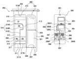
상기 세제박스(254)는 상기 컨트롤 패널(222)의 개구홀(222A)에 인출 가능하게 삽입되고 분말 세제와 유연제 및 표백제가 수용되는 세제 수용부(262)가 구비된 세제박스 본체(260)와, 상기 세제박스 본체(260)의 전면에 장착되어 상기 컨트롤 패널(222)의 개구홀(222A) 전방에 배치되고 일측에 손잡이(272)가 형성된 전면 패널(270)과, 상기 세제 수용부(262)의 상면에 장착되는 세제박스 캡(280)과, 상기 세제박스(254)의 인출시 임의로 탈거되지 않도록 상기 세제박스 본체(260)의 하부에 형성된 탈거방지수단(320)을 포함하여 구성된다.The
상기 세제박스 본체(260)는 상면과 후면이 개구된 박스 형상으로 형성되는 바, 전면에 상기 전면 패널(270)이 장착되는 전면부(264)가 형성되고, 상기 세제박스 본체(260)의 양측벽부(265)(266) 사이에는 구획 측벽부(268)가 전후방향으로 길게 형성된다.The
상기 세제 수용부(262)는 상기 구획 측벽부(268)와 우측벽부(265) 사이에 전후방향으로 길게 형성되어 분말 세제가 수용되는 제 1 세제 수용부(300)와, 상기 구획 측벽부(268)와 좌측벽부(265) 사이에 전후방향으로 길게 형성되어 유연제와 표백제가 수용되는 제 2 세제 수용부(310)로 이루어진다.The detergent
여기서, 상기 제 1 세제 수용부(300)는 상기 디스펜서 커버(256)로부터 분사되는 물에 의해 분말 세제가 덩어리 상태로 상기 세제박스 하우징(252)으로 낙하되지 않도록 후면에 차단벽(302)이 형성되고, 상기 제 1 세제 수용부(300)에 수용 가능한 세제 용량이 설정되도록 상기 전면 패널(270)에서 후방으로 소정 거리 이격된 위치에 세제량 설정벽(304)이 형성된다.Here, the
상기와 같은 차단벽(302)과 세제량 설정벽(304)은 좌우방향으로 수평하게 형성된 판형 부재로써, 상기 구획 측벽부(268)와 우측벽부(265)에 양측단이 각각 연결되고, 상기 제 1 세제 수용부(300)에 수용된 분말세제가 상기 세제박스 하우징(252)으로 배출될 수 있도록 상기 제 1 세제 수용부(300)의 바닥면(301)과 일정 간격 이격되게 형성된다.The
상기 차단벽(302)의 하측 바닥면(301)에는 물 또는 세제가 제 1 세제 수용부(300)로부터 배출되기 원활하도록 반원형의 배출홀부(306)가 형성된다.The
상기 세제량 설정벽(304)은 상기 세제박스(254)가 컨트롤 패널(222)의 개구홀(222A)로부터 최대로 인출될 때 상기 개구홀(222A)과 대응되는 위치에 형성되어 상기 제 1 세제 수용부(300)에 분말 세제가 투입되는 공간을 설정하게 된다.The detergent
즉, 상기 세제박스(254)가 전방으로 인출됨에 따라 상기 제 1,2 세제 수용부(300)(310)의 전방부가 개방되어 분말 세제, 유연제, 표백제 등이 투입되는 투입 공간(S)이 형성된다. 이때, 상기 투입 공간(S)은 상기 세제박스(254)가 최대로 인출되는 시점에서 최대 크기로 형성되므로, 상기 세제량 설정벽(304)은 상기 세제박스(254)의 최대 인출시 상기 개구홀(222A)과 대응되는 위치에 수직하게 형성되어 상기 제 1 세제 수용부(262)에 세제가 수용 가능한 용적을 제한하게 된다.That is, as the
이와 같이 세제량 설정벽(304)은 상기 개구홀(222A)의 후방에 상단이 배치됨과 아울러 상기 개구홀(222A) 전방에 하단이 배치되도록 상하방향으로 경사지게 형성된다.Thus, the detergent
따라서, 상기 세제량 설정벽(304)이 경사지게 형성되기 때문에 상기 세제박스 본체(260)의 사출 성형시 사출 금형이 용이하게 취출되고, 상기 세제량 설정벽(304)의 상단이 상기 개구홀(222A)의 내측에 위치되기 때문에 상기 세제량 설정벽(304)의 후방 공간으로 분말 세제가 투입되는 현상이 미연에 방지된다.Therefore, since the detergent
물론, 상기 상업용 세탁기(200)는 세탁 용량에 따라 상기 세제박스(254)에 투입되는 세제량이 변경되는 것은 사실이나, 최근에는 분말 세제의 세정 성능이 매우 우수하기 때문에 실제로 세탁에 필요한 세제량은 크게 감소되는 추세이므로, 분말 세제의 수용공간을 증가시킬 목적으로 상기 세제량 설정벽(304)의 형성 위치를 후방으로 이동시킬 필요가 없다.Of course, it is true that the
그리고, 제 2 세제 수용부(310)의 내부에는 좌측과 우측에 유연제가 수용되는 유연제 수용부(312)와 표백제가 수용되는 표백제 수용부(311)가 전후방향으로 길게 형성된다.In addition, a softener
상기와 같은 표백제 수용부(311)와 유연제 수용부(312)는 상기 제 2 세제 수용부(310)의 바닥면(311)에서 상측으로 소정 높이 이격된 위치에 상면이 개구된 박스형 구조로 형성된다.The
상기 표백제 수용부(311)는 상기 구획 측벽부(268)를 따라 전후 방향으로 길게 형성되고, 전방부에 소정의 넓이로 표백제 투입부(S1)가 형성되며, 후방부의 저면에 소정의 높이로 표백제 사이폰 관(313)이 돌출 형성된다.The
상기 유연제 수용부(312)는 상기 좌측벽부(266)를 따라 전후 방향으로 길게 형성되고, 상기 표백제 투입부(S1)의 후방에 위치되도록 전방부에 유연제 투입부(S2)가 소정의 넓이로 형성되며, 후방부의 저면에 소정의 높이로 유연제 사이폰 관(314)이 돌출 형성된다.The softener
한편, 상기 제 2 세제 수용부(310)는 상기 표백제 수용부(311)와 유연제 수용부(312)로 내부를 구획하도록 상기 표백제 수용부(311)와 유연제 수용부(312)의 저면으로부터 하측 구획리브(316)가 소정의 높이로 상향 돌출된다.On the other hand, the second
상기 하측 구획리브(316)는 상기 세제박스(254)의 최대 인출시 개방되는 제 2 세제 수용부(310)의 세제 투입공간(S)에 좌우방향으로 길게 형성되어 상기 표백제 수용부(311)와 유연제 수용부(312)의 세제가 투입되는 공간을 구획 형성하는 제 1 하측 구획리브(316A)와, 상기 제 1 하측 구획리브(316A)의 양측단 중 상기 제 2 세제 수용부(310)의 측면과 이격된 우측단으로부터 후방으로 길게 형성되어 상기 구획 측벽부(268)와의 사이에 유동 통로(315)를 형성하는 제 2 하측 구획리브(316B)와, 상기 제 2 하측 구획리브(316B)의 후단에서 상기 제 1 하측 구획리브(316A)와 평행하게 좌측으로 형성된 후 상기 구획 측벽부(268)와 좌측벽부(266) 사이의 중간 지점에서 후방으로 길게 형성된 제 3 하측 구획리브(316C)로 구성된다.The
여기서, 상기 제 1 하측 구획리브(316A)는 상기 세제 박스(254)의 최대 인출시 상기 제 2 세제 수용부(310)의 개방된 투입 공간(S)에 좌우방향으로 길게 형성되어 상기 표백제 투입구(S1)와 유연제 투입구(S2)가 구획 형성된다. 상기와 같은 표백제 투입부(S1)는 상기 제 1 하측 구획리브(316A)의 전방에 형성되고, 상기 유연제 투입부(S2)는 상기 제 1 하측 구획리브(316A)의 후방에 형성된다.Here, the first
상기 제 1 하측 구획리브(316A)의 좌측단은 상기 제 2 세제 수용부(310)의 좌측벽부(266)에 연결되고, 우측단은 상기 제 2 세제 수용부(310)의 구획 측벽부(268)와 소정 간격으로 이격된다. 이와 같은 제 1 하측 구획리브(316A)의 우측단은 상기 제 2 세제 수용부(310)의 폭 절반길이 보다 작은 간격으로 상기 구획 측벽부(268)와 이격된다.The left end of the first
그리고, 상기 제 2 하측 구획리브(316B)는 상기 제 1 하측 구획리브(316A)의 우측단에서 후방으로 길게 형성됨으로써, 상기 유연제 투입부(S2)와 구획 측벽부(268) 사이에는 상기 표백제 투입부(S1)에 투입된 표백제가 후방부로 유동되기 위한 유동 통로(315)가 형성된다.In addition, the second
상기 유동 통로(315)는 구조상 병목 구간으로 작용되는 바, 상기 유연제와 혼합된 물이 상기 표백제와 혼합된 물에 비해 점성이 크기 때문에, 상기 표백제와 혼합된 물이 유동 통로(315)로 유동되도록 상기 제 1 하측 구획리브(316A)의 전방에 표백제 투입부(S1)는 형성되는 것이 바람직하다.The
따라서, 상기와 같이 제 2 세제 수용부(310)의 내부 좌측과 우측에 상기 유연제 수용부(312)와 표백제 수용부(311)가 전후방향으로 길게 형성됨과 아울러 상기 제 2 세제 수용부(310)의 세제 투입공간(S)에 상기 표백제 투입부(S1)와 유연제 투입부(S2)가 전후로 배치되므로, 상기 제 2 세제 수용부(310)의 내부에 유연제 수용부(312)와 표백제 수용부(311)가 전후로 배치된 구조보다 상기 세제박스(254)의 최대 인출 거리가 최소화되고, 상기 표백제 투입부(S1)와 유연제 투입부(S2)가 좌우로 배치된 구조보다 상기 표백제 투입부(S1)와 유연제 투입부(S2)의 크기가 증대된다.Therefore, as described above, the
상기 제 2 세제 수용부(310)의 후면에는 상기 표백제 사이폰 관(313)과 유연제 사이폰 관(314)보다 높은 높이로 후벽부(317)가 형성된다.The
상기 후벽부(317)는 표백제와 유연제가 과 투입되거나 물의 과 급수될 경우 상기 세제박스 하우징(252)으로 표백제와 유연제 또는 물이 넘쳐흐를 수 있도록, 상단 중간부에는 넘침부(317B)가 형성된다.The
상기 넘침부(317B)는 상기 후벽부(317)의 양측단부에 비해 상대적으로 낮은 높이로 형성된다.The
특히, 상기 표백제 수용부(311)와 유연제 수용부(312)는 상기 표백제 사이폰 관(313)과 유연제 사이폰 관(314)이 형성된 부위가 하측으로 일정 깊이 융기된 구조로 형성되고, 상기 제 2 세제 수용부(310)의 바닥면(311)에는 상기 표백제 사이폰 관(313)과 유연제 사이폰 관(314)의 하측 전방이 차폐될 수 있도록 차폐벽(318)이 수직하게 형성된다.In particular, the
상기 차폐벽(318)은 상기 세제박스(254)가 개구홀(222A)에 삽입될 때 상기 표백제 사이폰 관(313)과 유연제 사이폰 관(314)의 하단부로 공기압이 작용될 수 있도록 상기 표백제 사이폰 관(313)과 유연제 사이폰 관(314)에서 전방으로 소정 거리 이격된 위치에 형성된다.The shielding
따라서, 상기 세제박스(254)의 닫힘시 상기 표백제 사이폰 관(313)과 유연제 사이폰 관(314)의 하부에 소정의 공기압이 작용되므로, 상기 표백제 수용부(311)와 유연제 수용부(312)에 저장된 표백제와 유연제가 유동됨으로서 상기 표백제 사이폰 관(313)과 유연제 사이폰 관(314)과 후술하는 표백제 사이폰 캡(285)과 유연제 사이폰 캡(286)을 통해 상기 제 2 세제 수용부(310)의 바닥면(311)으로 배출되는 현상이 미연에 방지된다.Therefore, when the
상기 전면 패널(270)은 상기 세제박스 본체(260)의 전면부(264)에 후크 결합됨과 아울러 체결볼트(274)에 의해 체결 고정된다.The
즉, 상기 전면부(264)와 전면 패널(270)에는 후크홀과 후크가 상호 대향되게 형성되어 상기 전면 패널(270)이 전면부(264)에 장착되고, 체결홀이나 체결보스가 상호 대향되게 형성되어 상기 체결볼트(274)에 의해 체결 고정된다. 따라서, 상기 전면 패널(270)은 상기 세제박스 본체(260)의 전면부(264)에 견고하게 장착 고정되기 때문에 상기 전면 패널(270)의 임의 탈거가 방지된다.That is, the
상기 세제박스 캡(280)은 상기 제 2 세제 수용부(310)의 상면에 덮힘되게 장착되는 판 형상의 부재로써, 전방부는 상기 제 2 세제 수용부(310)의 전방부에 형성된 안착부(319)에 올림 고정되고, 후방부는 상기 제 2 세제 수용부(310)의 후면에 형성된 후벽부(317)의 상단에 올림 고정된다.The
상기 안착부(319)에는 제 1 끼움홀(319A)이 상하 방향으로 관통 형성되고, 상기 세제박스 캡(280)의 전방부 하면에는 상기 제 1 끼움홀(319A)에 끼워져 걸림되는 제 1 끼움돌기(281)가 하향 돌출된다.The first
상기 후벽부(317)의 상단 배면에는 제 2 끼움돌기(317A)가 후방으로 돌출되고, 상기 세제박스 캡(280)의 하면 후방부에는 상기 제 2 끼움돌기(317A)가 끼워져 걸림되도록 제 2 끼움홀(282A)이 형성된 밀착부(282)가 하향 돌출된다.The second
상기 밀착부(282)는 상기 후벽부(317)의 상단 배면에 밀착되게 형성된다.The
따라서, 상기 세제박스 캡(280)은 상기 제 1,2 끼움홀(319A)(282A)과 제 1,2 끼움돌기(281)(317A)에 의해 상기 세제박스 본체(262)에 견고하게 장착될 뿐만 아니라, 상기 세제박스(254)의 인출시 상기 제 1,2 끼움돌기(281)(317A)가 외측으로 드러나지 않아 고객에 의해 임의로 탈거되는 현상도 방지된다.Thus, the
한편, 상기 세제박스 캡(280)은 상기 표백제 투입부(S1)와 대응되는 부위에 표백제와 물이 투입되는 표백제 투입구(283)가 형성되고, 상기 유연제 투입부(S2)와 대응되는 부위에 유연제와 물이 투입되는 유연제 투입구(284)가 형성된다.On the other hand, the
그리고, 상기 표백제 수용부(311)와 유연제 수용부(312)에 형성된 사이폰 관(313)(314)과 대응되는 부위에는 상기 표백제 사이폰 관(313)과 유연제 사이폰 관(314)의 상단부에 씌워지는 표백제 사이폰 캡(285)과 유연제 사이폰 캡(286)이 각각 형성된다.The upper portion of the bleach siphon
상기 표백제 투입구(283)와 유연제 투입구(284)는 중앙에 홀이 형성된 사각 형상으로 소정 깊이 하측으로 융기된 구조로 형성된다.The
상기 표백제 사이폰 캡(285)과 유연제 사이폰 캡(286)이 형성된 부위에는 소정 깊이 하측으로 융기된 융기부(289A)(289B)가 각각 형성되고, 상기 융기부(289A)(289B)에는 상기 표백제 사이폰 캡(285)과 유연제 사이폰 캡(286)의 전방으로 물이 투입될 수 있도록 표백제 보조 투입구(287)와 유연제 보조 투입구(288)가 각각 형성된다.The portions where the bleach siphon
상기 표백제 보조 투입구(287)와 유연제 보조 투입구(288)는 상기 융기부(289A)(289B)의 전방부에서 사각형 구조로 하향 돌출되되, 상기 보조 투입구(287)(288)에는 복수개의 그릴이 일체로 형성된다. 따라서, 상기 표백제 보조 투입구(287)와 유연제 보조 투입구(288)를 통해 상기 표백제 사이폰 캡(285)과 유연제 사이폰 캡(286)으로 물과 함께 유동되는 표백제와 유연제에 추가적으로 물이 분사되어 상기 표백제와 유연제의 희석을 촉진시키게 된다.The bleach
상기와 같은 세제박스 캡(280)의 하면에는 상기 세제박스 본체(260)의 하측 구획리브(316)와 밀착되도록 상측 구획리브(290)가 하향 돌출된다.The
즉, 상기 상측 구획리브(290)는 상기 제 1 하측 구획리브(316A)의 후면에 밀착되도록 좌우방향으로 형성되어 상기 표백제 투입구(283)와 유연제 투입구(284)를 구획하는 제 1 상측 구획리브(290A)와, 상기 제 2 하측 구획리브(316B)의 좌측면에 밀착되도록 상기 제 1 상측 구획리브(290A)의 우측단으로부터 후방으로 길게 형성되어 상기 구획 측벽부(268)와의 사이에 유동 통로(315)를 형성하는 제 2 상측 구획리브(290B)와, 상기 제 3 하측 구획리브(316C)의 전면과 좌측면에 밀착되도록 상기 제 2 상측 구획리브(290B)의 후단부로부터 상기 제 1 상측 구획리브(290A)와 평행하게 좌측으로 형성된 후 상기 세제박스 캡(280)의 중간 지점에서 후방으로 길게 형성된 제 3 상측 구획리브(290C)로 구성된다.That is, the
상기 제 1 상측 구획리브(290A)의 전방에는 상기 제 1 하측 구획리브(316A)의 전면에 밀착되는 제 1 고정리브(292)가 돌출되고, 상기 제 3 상측 구획리브(290C)의 우측에는 상기 제 3 하측 구획리브(316C)의 우측면에 밀착되는 제 2,3 고정리브(294)(296)가 돌출된다.A
따라서, 상기 세제박스 캡(280)이 장착됨에 따라 상기 제 1 하측 구획리브(316A)는 상기 제 1 상측 구획리브(290A)와 제 1 고정리브(292) 사이에 끼움 고정되고, 상기 제 3 하측 구획리브(316C)는 상기 제 3 상측 구획리브(290C)와 제 2,3 고정리브(294)(296) 사이에 끼움 고정된다.Therefore, as the
상기 탈거방지수단(320)은 상기 상업용 드럼 세탁기(200)로부터 세제박스(254)가 용이하게 탈거되지 않도록, 상기 세제박스 본체(260)의 구획 측벽부(268) 하측에 형성된다. 따라서, 상기 탈거방지수단(320)이 보이지 않는 위치에 형성됨으로써, 상기 세제박스(254)가 고객에 의해 임의로 완전히 탈거되는 현상이 미연에 방지된다.The detachment preventing means 320 is formed below the partition
상기와 같은 탈거방지수단(320)은 상기 제 1 세제 수용부(300)와 제 2 세제 수용부(310)의 하부에 좌측단과 우측단이 연결된 패널부(322)와, 상기 세제박스(254)의 인출시 상기 컨트롤 패널(222)의 개구홀(222A)에 걸림되도록 상기 패널부(322)의 일측에 돌출 형성된 돌기부(324)로 구성된다.The stripping prevention means 320 is a
여기서, 상기 패널부(322)는 상기 세제박스 본체(260)에 일체로 사출 성형된 판형 부재로써, 상기 제 1 세제 수용부(300)와 제 2 세제 수용부(310) 사이에 전후방향으로 길게 형성된다.Here, the
상기 패널부(322)는 상기 세제박스 본체(260)의 후방부 하측에 수평하게 형성되되, 상기 패널부(322)의 좌측과 우측에는 두 개의 슬릿(325A)(325B)이 상기 패널부(322)의 길이 방향으로 길게 형성되어 상기 두 개의 슬릿(325A)(325B) 사이에는 탄성부(326)가 누름 가능하게 형성된다.The
즉, 상기 탄성부(326)는 좌측단과 우측단에 상기 좌측 슬릿(325A)과 우측 슬릿(325B)이 각각 배치되고, 상기 패널부(322)에 전단과 후단이 탄성적으로 연결된다. 따라서, 상기 전단과 후단 사이의 중간 부위는 상하방향으로 탄성 변형이 가능하게 된다.That is, the
그리고, 상기 돌기부(324)는 상기 세제박스(254)의 인출시 상기 컨트롤 패널(222)의 개구홀(222A) 하단부에 걸림될 수 있도록 상기 탄성부(326)의 하면에 소정의 높이로 하향 돌출된 리브이다.In addition, the
이와 같은 돌기부(324)는 상기 탄성부(326)의 후방부 하면에 ‘ㄷ’형상으로 형성된다.The
즉, 상기 돌기부(324)는 상기 탄성부(326)의 하면에 좌우방향으로 길게 형성된 수직 리브(327)와, 상기 수직 리브(327)의 좌측단과 우측단에서 후방으로 각각 길게 형성된 경사 리브(328)로 이루어진다.That is, the
상기 수직 리브(327)는 상기 세제박스(254)의 인출시 상기 개구홀(222A)의 하단부에 걸림되도록 상기 탄성부(326)에서 수직하게 돌출되고, 상기 경사 리브(328)는 상기 수직 리브(327)를 지지함과 아울러 상기 세제박스(254)의 장착시 상기 개구홀(222A)에 삽입이 용이하도록 상기 수직 리브(327)에서 후방으로 갈수록 돌출 높이가 낮아지는 구조로 경사지게 형성된다.The
따라서, 상기 세제박스(254)가 컨트롤 패널(222)의 개구홀(222A)에 삽입하는 경우에는, 상기 개구홀(222A)의 하단과 접촉되면서 상기 경사 리브(328)가 상측으로 이동되고, 상기 돌기부(324)가 상기 개구홀(222A)의 내부로 완전히 삽입되면 상기 개구홀(222A)의 하단에 수직 리브(327)가 밀착 걸림된다.Accordingly, when the
반면에, 상기 세제박스(254)가 컨트롤 패널(222)의 개구홀(222A)로부터 완전히 탈거하고자 하는 경우에는, 상기 수직 리브(327)가 개구홀(222A)의 하단에 걸림되지 않도록 상기 탄성부(326)를 충분히 상측으로 누른 상태에서 상기 세제박스(254)를 전방으로 인출하게 된다.On the other hand, when the
상기 디스펜서 커버(256)는 상기 세제박스 하우징(252)의 개방된 상면에 장착되는 하부 패널(256A)과, 상기 하부 패널(256A)과 함께 세제 급수 유로(330)와 표백제 급수 유로(332) 및 유연제 급수 유로(334)를 형성하도록 상기 하부 패널(256A)의 상부에 올림 장착된 상부 패널(256B)로 구성된다.The
상기 하부 패널(256A)은 상기 급수장치(230)의 급수호스(232)와 연결되는 호스 연결부(338)가 후방부에 돌출 형성되고, 상기 세제박스(254)의 제 1,2 세제 수용부(300)(310)와 대향되는 부위에는 물을 급수하는 복수개의 급수홀이 형성된다.The
여기서, 상기 호스 연결부(338)는 상기 세제 급수 유로(330)로 온수가 급수되도록 온수호스(232C)가 연결되는 제 1 호스 연결부(338A)와, 상기 표백제 급수 유로(332)와 유연제 급수 유로(334) 및 세제 급수 유로(330)로 냉수가 급수되도록 제 1,2 냉수호스(232A)(232B)가 연결되는 제 2,3 호스 연결부(338B)(388C)로 구성된다.Here, the
그리고, 상기 급수홀은 상기 제 2 세제 수용부(310)의 내부로 물이 수직하게 분사되도록 상기 하부 패널(256A)의 하면 일측에 형성된 제 1 급수홀(340)과, 상기 제 1 세제 수용부(300)의 내측면으로 물이 경사지게 분사되도록 상기 하부 패널(256A)의 하면 타측에 형성된 제 2 급수홀(342)로 이루어진다.The water supply hole includes a first
상기 제 1 급수홀(340)은 상기 하부 패널(256A)에 상하방향으로 관통되게 형성되는 바, 상기 표백제 급수 유로(332) 내의 물이 상기 표백제 수용부(311)에 급수되도록 상기 표백제 수용부(311)의 상측에 형성된 복수개의 표백제 급수홀(344)과, 상기 유연제 급수 유로(334) 내의 물이 상기 유연제 수용부(312)에 급수되도록 상기 유연제 수용부(312)의 상측에 형성된 복수개의 유연제 급수홀(346)로 구성된다.The first
상기 표백제 급수홀(344)은 상기 표백제 투입구(283) 및 표백제 보조 투입구(287)와 대향되는 부위에 각각 형성되고, 상기 유연제 급수홀(346)은 상기 유연제 투입구(284) 및 유연제 보조 투입구(288)와 대향되는 부위에 각각 형성된다.The
상기 제 2 급수홀(342)은 상기 세제 급수 유로(330) 내의 물이 상기 제 1 세제 수용부(300)에 급수되도록 상기 제 1 세제 수용부(300)의 상측에 형성되되, 상기 제 1 세제 수용부(300)의 내측면을 따라 복수개가 형성된다.The second
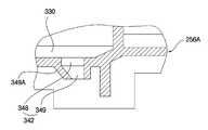
이와 같은 제 2 급수홀(342)은 상기 하부 패널(256A)에 상하방향으로 수직하게 관통된 수직홀부(348)와, 상기 수직홀부(348)와 연통되게 하부 패널(256A)의 하면으로부터 하향 돌출되고 일부분이 경사지게 형성된 보스부(349)로 구성된다.The second
상기 보스부(349)는 상기 제 1 세제 수용부(300)의 내측면과 가까운 일측이 상기 하부 패널(256A)의 하면으로부터 수직하게 하향 돌출되고, 상기 제 1 세제 수용부(300)의 내측면과 먼 타측이 상기 하부 패널(256A)의 하면으로부터 상기 제 1 세제 수용부(300)의 내측면 측으로 하향 경사지게 돌출된다.One side of the
따라서, 상기 보스부(349)의 일측이 수직하게 형성됨과 아울러 상기 보스부(349)의 타측이 경사지게 돌출되므로, 상기 보스부(349)의 타측에 형성된 경사 부위(349A)에 의해 상기 제 2 급수홀(342)로부터 분사되는 물은 상기 제 1 세제 수용부(300)의 내측면으로 경사지게 분사되고, 아울러 상기 경사 부위(349A)로 인해 제 2 급수홀(342)의 통로 면적이 좁아지는 구조로 형성되어 상기 제 2 급수홀(342)을 통해 분사되는 물의 수압은 상승된다.Therefore, since one side of the
한편, 상기 제 1,2,3 호스 연결부(338A)(338B)(338C)에서 상기 제 2 급수홀(342)로 냉수 또는 온수가 유동되게 상기 세제 급수 유로(330)가 형성되고, 상기 제 2,3 호스 연결부(338B)(388C)에서 상기 표백제 급수홀(344)로 냉수가 유동되게 상기 표백제 급수 유로(332)가 형성되며, 상기 제 2,3 호스 연결부(338B)(388C)에서 상기 유연제 급수홀(346)로 냉수가 유동되게 상기 유연제 급수 유로(334)가 형성된다.Meanwhile, the detergent
상기 세제 급수 유로(330)와 표백제 급수 유로(332) 및 유연제 급수 유로(334)는 상기 제 2 급수홀(342)과 표백제 급수홀(344) 및 유연제 급수홀(346)이 형성된 부위의 저면이 다른 부위에 비해 낮게 형성된다.The detergent
따라서, 상기 제 2 급수홀(342)과 표백제 급수홀(344) 및 유연제 급수홀(346)이 형성된 부위는 다른 부위에 비해 유로의 용적이 증대되고, 저면의 높이가 달라지는 단차진 부위(336)로 인해 물의 역류가 방지된다.Accordingly, in the portion where the second
상기 상부 패널(256B)과 하부 패널(256A) 중 적어도 어느 하나에는 상기 세제 급수 유로(330)를 형성하는 세제 급수 리브(331)와, 상기 표백제 급수 유로(332)를 형성하는 표백제 급수 리브(333)와, 상기 유연제 급수 유로(334)를 형성하는 유연제 급수 리브(336)가 돌출되게 형성된다.At least one of the
상기와 같은 상부 패널(256B)과 하부 패널(256A)은 열융착되어 조립된다.The
상기와 같이 구성된 본 발명에 따른 상업용 드럼 세탁기의 세제공급기구에 관한 작동과 조립과정을 살펴보면 다음과 같다.Looking at the operation and assembly process of the detergent supply mechanism of a commercial drum washing machine according to the present invention configured as described above are as follows.
먼저, 상기 상업용 드럼 세탁기(200)에 의해 세정물을 세탁하기 전에 세제공급기구(250)에는 적당량의 분말 세제와 표백제 및 유연제가 투입된다.First, an appropriate amount of powder detergent, bleach, and softening agent is added to the
즉, 상기 세제공급기구(250)의 세제박스(254)는 컨트롤 패널(222)의 개구홀(222A)에서 전방으로 인출되어 세제 수용부(262)가 개방되되, 상기 세제박스(254)의 하부에 형성된 탈거방지수단(320)의 돌기부(324)가 개구홀(222A)의 하단부에 걸림될 때까지 전방으로 인출된다.That is, the
따라서, 상기 세제박스(254)에 분말 세제와 표백제 및 유연제를 투입하기 위한 공간(S)은 상기 돌기부(324)가 개구홀(222A)에 걸림되는 위치에서 최대가 된다.Therefore, the space S for injecting the powder detergent, the bleach, and the softening agent into the
상기와 같은 세제박스(254)의 투입 공간(S)을 통해 상기 제 1 세제 수용부(300)에는 분말 세제가 투입되고, 상기 제 2 세제 수용부(310)의 표백제 수용부(311)에는 표백제가 투입되며, 상기 제 2 세제 수용부(310)의 유연제 수용부(312)에는 유연제가 투입된다.Powder detergent is introduced into the first
상기 제 1 세제 수용부(300)는 분말 세제가 투입되는 공간(S)이 최대가 되는 위치에 세제량 설정벽(304)이 형성되어 상기 제 1 세제 수용부(300)에 세제가 과다하게 투입되는 현상이 방지된다. 즉, 최근의 분말 세제는 세정 성능이 매우 우수하기 때문에 상기 세제박스(254)에 소량의 분말 세제만 투입하더라도 세정물의 세정 성능이 충분히 확보된다.Detergent
상기 제 2 세제 수용부(310)의 상면에는 세제박스 캡(280)이 장착되어 있는 바, 상기 표백제는 상기 세제박스 캡(280)의 표백제 투입구(283)를 통해 상기 제 2 세제 수용부(310)의 표백제 수용부(311)에 투입되고, 상기 유연제는 상기 세제박스 캡(280)의 유연제 투입구(284)를 통해 상기 제 2 세제 수용부(310)의 유연제 수용부(312)에 투입된다.The
이와 같이 세제박스(254)의 세제 수용부(262)에 분말 세제, 표백제, 유연제가 투입되면, 상기 컨트롤 패널(222)의 개구홀(222A) 내측으로 상기 세제박스(254)가 삽입되어 상기 세제박스(254)는 세제박스 하우징(252)의 내측에 배치된다.When the powder detergent, bleach, and softener are introduced into the
그리고, 상기 세제가 투입된 상업용 드럼 세탁기(200)가 작동되면, 상기 급수장치(230)의 급수호스(232)를 통해 외부로부터 물이 상기 세제공급기구(250)의 내부로 급수된다.When the commercial
즉, 상기 급수장치(230)의 급수호스(232)와 연결된 호스 연결부(338)를 통해 상기 세제공급기구(250)의 디스펜서 커버(256)로 물이 유입되고, 상기 디스펜서 커버(256)의 내부로 유입된 물은 세제 급수 유로(330)와 표백제 급수 유로(332) 및 유연제 급수 유로(334)를 따라 제 2 급수홀(342)과 표백제 급수홀(344) 및 유연제 급수홀(346)로 유동되고, 상기 제 2 급수홀(342)과 표백제 급수홀(344) 및 유연제 급수홀(346)을 통해 세제박스(254)의 제 1 세제 수용부(300)와 표백제 수용부(311) 및 유연제 수용부(312)로 배출된다.That is, water flows into the
상기 제 2 급수홀(342)을 통해 배출되는 물은 상기 제 1 세제 수용부(300)의 내부로 급수되되, 상기 제 2 급수홀(342)의 보스부(349)에 형성된 경사 부위(349A)로 인해 상기 제 1 세제 수용부(300)의 내측면으로 비스듬하게 분사되어 상기 제 1 세제 수용부(300)에 투입된 분말 세제가 보다 효과적으로 씻겨 내려가게 된다.The water discharged through the second
이와 같이 물에 의해 씻겨 내려가는 분말세제는 상기 제 1 세제 수용부(300)의 바닥면과 세제량 설정벽(304) 사이를 통과한 후 상기 제 1 세제 수용부(300)의 바닥면과 차단벽(302) 사이에 형성된 공간과 배출홀부(306)를 통해 상기 세제박스 하우징(252)의 내부로 배출된다.As such, the powder detergent washed down by the water passes between the bottom surface of the first
특히, 상기 보스부(349)는 물이 유입되는 상단부에 비해 물이 토출되는 하단부의 단면적이 작게 형성된 노즐 구조로 형성되므로, 상기 보스부(349)를 통해 분사되는 물의 수압이 상승되어 분말세제의 배출 성능이 향상된다.In particular, since the
상기 표백제 급수홀(344)과 유연제 급수홀(346)을 통해 배출되는 물은 표백제 투입구(283)와 유연제 투입구(284) 및 표백제 보조 투입구(287)와 유연제 보조 투입구(288)로 각각 급수되고, 상기 표백제 수용부(311)와 유연제 수용부(312)에 급수된 물에 의해 표백제와 유연제는 희석된다. Water discharged through the
상기 표백제 투입구(283)와 유연제 투입구(284)에 물이 급수되어 수위가 일정높이 이상으로 상승되면, 상기 표백제 또는 유연제가 희석된 물은 상기 표백제 투입구(283)와 유연제 투입구(284)에 형성된 사이폰 관(313)(314)과 사이폰 캡(285)(286)을 통해 상기 세제박스 하우징(252)의 내부로 사이폰 현상에 의해 단 한번에 완전히 배출된다.When water is supplied to the
특히, 상기 세제박스 캡(280)에는 사이폰 캡(285)(286)의 전방에 표백제 보조 투입구(287)와 유연제 보조 투입구(288)가 형성되므로, 상기 사이폰 관(313)(314)과 사이폰 캡(285)(286)으로 유입되는 표백제와 유연제에 물이 추가적으로 분사되어 상기 표백제와 유연제가 완전하게 희석된다.In particular, the
이때, 상기 표백제 보조 투입구(287)와 유연제 보조 투입구(288)에는 그릴이 형성되어 상기 표백제 보조 투입구(287)와 유연제 보조 투입구(288)를 통해 분사되는 물의 수압을 향상시키게 된다.In this case, a grill is formed in the bleach
상기와 같이 표백제와 유연제가 상기 표백제 보조 투입구(287)와 유연제 보조 투입구(288)를 통해 분사되는 물에 의해 완전하게 희석되면, 상기 사이폰 관(313)(314)과 사이폰 캡(285)(286)에 점액질 상태로 도달되지 않아 사이폰 현상이 원활하게 진행되고, 상기 사이폰 관(313)(314)과 사이폰 캡(285)(286)을 통해 배출되는 표백제와 유연제의 배출 성능이 확보된다.As described above, when the bleach and the softener are completely diluted by the water sprayed through the bleach
상기 분발세제와 표백제 및 유연제가 용해된 물은 세제박스 하우징(252)의 내부로 배출된 후 급수 밸로우즈(236)를 통해 터브(206)로 공급된다.The water in which the powder detergent, the bleach, and the softener are dissolved is discharged into the
한편, 상기 세제 급수 유로(330)와 표백제 급수 유로(332) 및 유연제 급수 유로(334)는 상기 제 2 급수홀(342)과 표백제 급수홀(344) 및 유연제 급수홀(346)이 형성된 부위가 다른 부위에 비해 저면이 낮게 형성된다.Meanwhile, the detergent
따라서, 상기 제 2 급수홀(342)과 표백제 급수홀(344) 및 유연제 급수홀(346)이 형성된 부위는 다른 부위에 비해 물 수용량이 증대될 뿐만 아니라 상기 제 2 급수홀(342)과 표백제 급수홀(344) 및 유연제 급수홀(346)이 형성된 부위에서 상기 제 1,2,3 호스 연결부(338A)(338B)(338C)로 물의 역류가 방지된다.Therefore, the portion of the second
또한, 상기 디스펜서 커버(256)의 제 1 호스 연결부(338A)에는 온수밸브(234C)에 의해 공급되는 고온의 온수가 온수 호스(232C)를 통해 유입되고, 상기 제 2 호스 연결부(338B)에는 냉수밸브(234A)에 의해 공급되는 냉수가 제 1 냉수 호스(232A)를 통해 유입되고, 상기 제 3 호스 연결부(338C)에는 냉수밸브(234B)에 의해 공급되는 냉수가 제 2 냉수 호스(232B)를 통해 유입된다.In addition, high temperature hot water supplied by the
상기 온수 호스(232C)를 통해 고온의 온수가 공급되도록 상기 온수밸브(234C)가 개방되면, 상기 제 1 호스 연결부(338A)를 통과한 고온의 온수가 세제 급수유로(330)를 따라 상기 제 2 급수홀(342)로 유동되고, 상기 제 2 냉수 호스(232B)를 통해 냉수가 공급되도록 상기 냉수밸브(234B)가 개방되면, 상기 제 3 호스 연결부(338C)를 통과한 냉수가 세제 급수유로(330)를 따라 상기 제 2 급수홀(342)로 유동된다.When the
그리고, 상기 온수 호스(232C)와 제 2 냉수 호스(232B)를 통해 고온의 온수와 냉수가 동시에 공급되도록 상기 온수밸브(234C)와 냉수밸브(234B)가 개방되면, 상기 제 1,3 호스 연결부(338A)(338B)를 통과한 고온의 온수와 냉수가 중온의 온수로 섞이면서 세제 급수유로(330)를 따라 상기 제 2 급수홀(342)로 유동된다.When the
특히, 상기 제 1 냉수 호스(232A)를 통해 냉수가 공급되도록 상기 냉수밸브(234A)가 개방되면, 상기 제 2 호스 연결부(338B)를 통과한 냉수가 유연제 급수유로(334)를 따라 상기 유연제 급수홀(346)로 유동되며, 상기 제 1,2 냉수호스(232A)(232B)를 통해 냉수가 공급되도록 상기 냉수밸브(234A)(234B)가 개방되면, 상기 제 2,3 호스 연결부(338A)(338B)를 통과한 냉수가 서로 간섭되어 표백제 급수유로(332)를 따라 상기 표백제 급수홀(344)로 유동된다.In particular, when the
이와 같이 본 발명에 의한 상업용 세정장치의 급수방법을 예시된 도면을 참조로 하여 설명하였으나, 본 발명은 상기의 실시예와 도면에 의해 한정되지 않고, 그 발명의 기술사상 범위 내에서 당업자에 의해 다양한 변형이 가능함은 물론이다.As described above, the water supply method of the commercial cleaning apparatus according to the present invention has been described with reference to the illustrated drawings. Of course, variations are possible.
상기와 같이 구성된 본 발명에 따른 상업용 세정장치의 급수방법은 제 1 설정시간까지 냉수가 간헐적으로 급수된 후 세정물의 세탁 코스에 따라 냉수 또는 온수가 설정수위까지 연속적으로 급수되고 제 2 설정시간동안 급수가 정지된 후 설정수위까지 다시금 재 급수되므로, 세정물의 포량을 감지하지 않더라도 세탁 코스에 따라 설정수위까지 냉수와 온수가 적절히 공급되어 급수시간이 단축되는 이점이 있다.In the water supply method of the commercial cleaning device according to the present invention configured as described above, after the cold water is intermittently supplied to the first set time, the cold or hot water is continuously supplied to the set water level according to the washing course of the washing water, and the water is supplied for the second set time. Since the water is re-supplied to the set water level again after stopping, the water supply time is shortened by supplying cold water and hot water properly up to the set water level according to the washing course even if the quantity of the cleaning water is not detected.
또한, 상기 상업용 세정장치는 세정물의 종류에 따라 고온의 온수세탁과 중온의 온수세탁 및 냉수세탁이 선택적으로 진행되므로, 상기 세정물의 세탁 성능이 향상되고, 중온의 온수세탁이 가능하기 때문에 고온의 온수로 인한 세정물이 열 손상과 변형이 방지되는 이점이 있다.In addition, since the commercial washing apparatus selectively proceeds with hot hot water washing, medium hot water washing, and cold water washing according to the type of washing product, washing performance of the washing product is improved, and hot water washing of medium temperature is possible, so that high temperature hot water washing is performed. Cleans due to have the advantage of preventing heat damage and deformation.
또한, 상기 상업용 세정장치는 세제공급기구로부터 세정물에 세제가 공급되거나 중온의 온수세탁 및 냉수세탁시 냉수가 설정수위까지 재 급수될 경우 냉수가 사용되므로, 온수의 불필요한 사용량이 최소화되는 이점이 있다.In addition, the commercial cleaning device has the advantage that the cold water is used when the detergent is supplied to the cleaning material from the detergent supply mechanism or when the cold water is re-watered to the set water level during the hot water washing and cold water washing of the medium temperature, unnecessary use of hot water is minimized. .
Claims (5)
Translated fromKoreanPriority Applications (1)
| Application Number | Priority Date | Filing Date | Title |
|---|---|---|---|
| KR1020050058120AKR101155336B1 (en) | 2005-06-30 | 2005-06-30 | Water supply method of commercial cleaning device |
Applications Claiming Priority (1)
| Application Number | Priority Date | Filing Date | Title |
|---|---|---|---|
| KR1020050058120AKR101155336B1 (en) | 2005-06-30 | 2005-06-30 | Water supply method of commercial cleaning device |
Publications (2)
| Publication Number | Publication Date |
|---|---|
| KR20070002540Atrue KR20070002540A (en) | 2007-01-05 |
| KR101155336B1 KR101155336B1 (en) | 2012-06-11 |
Family
ID=37869515
Family Applications (1)
| Application Number | Title | Priority Date | Filing Date |
|---|---|---|---|
| KR1020050058120AExpired - Fee RelatedKR101155336B1 (en) | 2005-06-30 | 2005-06-30 | Water supply method of commercial cleaning device |
Country Status (1)
| Country | Link |
|---|---|
| KR (1) | KR101155336B1 (en) |
Cited By (5)
| Publication number | Priority date | Publication date | Assignee | Title |
|---|---|---|---|---|
| KR101435813B1 (en)* | 2007-11-27 | 2014-08-29 | 엘지전자 주식회사 | Laundry processing apparatus and control method thereof |
| EP3690115A1 (en)* | 2019-02-01 | 2020-08-05 | LG Electronics Inc. | Laundry treating apparatus and water supply control method thereof |
| KR20200096038A (en)* | 2019-02-01 | 2020-08-11 | 엘지전자 주식회사 | Laundry treating apparatus and water supply control method |
| KR20200096036A (en)* | 2019-02-01 | 2020-08-11 | 엘지전자 주식회사 | Laundry treating apparatus |
| US11371176B2 (en)* | 2019-02-01 | 2022-06-28 | Lg Electronics Inc. | Laundry treating apparatus |
Families Citing this family (1)
| Publication number | Priority date | Publication date | Assignee | Title |
|---|---|---|---|---|
| DE102012223682A1 (en)* | 2012-12-19 | 2014-06-26 | BSH Bosch und Siemens Hausgeräte GmbH | Water-bearing domestic appliance with internal surface and method of operation |
Family Cites Families (2)
| Publication number | Priority date | Publication date | Assignee | Title |
|---|---|---|---|---|
| JPH0531290A (en)* | 1991-08-01 | 1993-02-09 | Hitachi Ltd | Water temperature controlling device for fully automatic washing machine |
| KR19980075007A (en)* | 1997-03-28 | 1998-11-05 | 배순훈 | How to control cold and hot water in the washing machine |
- 2005
- 2005-06-30KRKR1020050058120Apatent/KR101155336B1/ennot_activeExpired - Fee Related
Cited By (9)
| Publication number | Priority date | Publication date | Assignee | Title |
|---|---|---|---|---|
| KR101435813B1 (en)* | 2007-11-27 | 2014-08-29 | 엘지전자 주식회사 | Laundry processing apparatus and control method thereof |
| EP3690115A1 (en)* | 2019-02-01 | 2020-08-05 | LG Electronics Inc. | Laundry treating apparatus and water supply control method thereof |
| KR20200096038A (en)* | 2019-02-01 | 2020-08-11 | 엘지전자 주식회사 | Laundry treating apparatus and water supply control method |
| CN111519400A (en)* | 2019-02-01 | 2020-08-11 | Lg电子株式会社 | Laundry treating apparatus and water supply control method thereof |
| KR20200096036A (en)* | 2019-02-01 | 2020-08-11 | 엘지전자 주식회사 | Laundry treating apparatus |
| AU2020200736B2 (en)* | 2019-02-01 | 2021-07-22 | Lg Electronics Inc. | Laundry treating apparatus and water supply control method thereof |
| US11293126B2 (en) | 2019-02-01 | 2022-04-05 | Lg Electronics Inc. | Laundry treating apparatus and water supply control method thereof |
| US11371176B2 (en)* | 2019-02-01 | 2022-06-28 | Lg Electronics Inc. | Laundry treating apparatus |
| CN111519400B (en)* | 2019-02-01 | 2023-01-24 | Lg电子株式会社 | Laundry treating apparatus and water supply control method thereof |
Also Published As
| Publication number | Publication date |
|---|---|
| KR101155336B1 (en) | 2012-06-11 |
Similar Documents
| Publication | Publication Date | Title |
|---|---|---|
| KR101203554B1 (en) | Detergent applying apparatus of cleaning device | |
| KR101203552B1 (en) | Detergent applying apparatus of cleaning device | |
| EP1669487B1 (en) | Washing machine combined with dryer | |
| KR20130033225A (en) | Detergent dispenser and clothes treating apparatus with the same | |
| KR101152378B1 (en) | Washing method of cleaning device | |
| KR20070002540A (en) | Water Supply Method of Commercial Washing Equipment | |
| KR101155483B1 (en) | Detergent applying apparatus of cleaning device | |
| KR200399779Y1 (en) | Detergent box of detergent applying apparatus | |
| KR101203555B1 (en) | Commercial cleaning apparatus | |
| KR200399777Y1 (en) | Detergent box of detergent applying apparatus | |
| KR101155482B1 (en) | Detergent applying apparatus of cleaning device | |
| KR101155484B1 (en) | Detergent applying apparatus of cleaning device | |
| KR101155481B1 (en) | Detergent applying apparatus of cleaning device | |
| KR101203553B1 (en) | Detergent applying apparatus of cleaning device | |
| KR200399778Y1 (en) | Top plate mounting structure of commercial cleaning apparatus | |
| KR101234068B1 (en) | Burner of dryer and laundry piping system using it | |
| KR101263863B1 (en) | Top plate mounting structure of cleaning apparatus | |
| KR200396933Y1 (en) | Dryer | |
| KR200399775Y1 (en) | Commercial cleaning apparatus | |
| KR200399776Y1 (en) | Commercial cleaning apparatus | |
| KR200396934Y1 (en) | Dryer | |
| KR200402870Y1 (en) | Card reader machine Mounting structure of commercial cleaning apparatus | |
| KR200399780Y1 (en) | Commercial cleaning apparatus | |
| KR20070001609A (en) | Commercial cleaning device | |
| KR20070015279A (en) | Drying method of commercial dryer |
Legal Events
| Date | Code | Title | Description |
|---|---|---|---|
| PA0109 | Patent application | St.27 status event code:A-0-1-A10-A12-nap-PA0109 | |
| PG1501 | Laying open of application | St.27 status event code:A-1-1-Q10-Q12-nap-PG1501 | |
| PN2301 | Change of applicant | St.27 status event code:A-3-3-R10-R13-asn-PN2301 St.27 status event code:A-3-3-R10-R11-asn-PN2301 | |
| R18-X000 | Changes to party contact information recorded | St.27 status event code:A-3-3-R10-R18-oth-X000 | |
| R18-X000 | Changes to party contact information recorded | St.27 status event code:A-3-3-R10-R18-oth-X000 | |
| A201 | Request for examination | ||
| PA0201 | Request for examination | St.27 status event code:A-1-2-D10-D11-exm-PA0201 | |
| D13-X000 | Search requested | St.27 status event code:A-1-2-D10-D13-srh-X000 | |
| D14-X000 | Search report completed | St.27 status event code:A-1-2-D10-D14-srh-X000 | |
| PE0902 | Notice of grounds for rejection | St.27 status event code:A-1-2-D10-D21-exm-PE0902 | |
| P11-X000 | Amendment of application requested | St.27 status event code:A-2-2-P10-P11-nap-X000 | |
| P13-X000 | Application amended | St.27 status event code:A-2-2-P10-P13-nap-X000 | |
| E701 | Decision to grant or registration of patent right | ||
| PE0701 | Decision of registration | St.27 status event code:A-1-2-D10-D22-exm-PE0701 | |
| GRNT | Written decision to grant | ||
| PR0701 | Registration of establishment | St.27 status event code:A-2-4-F10-F11-exm-PR0701 | |
| PR1002 | Payment of registration fee | St.27 status event code:A-2-2-U10-U11-oth-PR1002 Fee payment year number:1 | |
| PG1601 | Publication of registration | St.27 status event code:A-4-4-Q10-Q13-nap-PG1601 | |
| FPAY | Annual fee payment | Payment date:20150424 Year of fee payment:4 | |
| PR1001 | Payment of annual fee | St.27 status event code:A-4-4-U10-U11-oth-PR1001 Fee payment year number:4 | |
| PN2301 | Change of applicant | St.27 status event code:A-5-5-R10-R13-asn-PN2301 St.27 status event code:A-5-5-R10-R11-asn-PN2301 | |
| FPAY | Annual fee payment | Payment date:20160422 Year of fee payment:5 | |
| PR1001 | Payment of annual fee | St.27 status event code:A-4-4-U10-U11-oth-PR1001 Fee payment year number:5 | |
| P22-X000 | Classification modified | St.27 status event code:A-4-4-P10-P22-nap-X000 | |
| FPAY | Annual fee payment | Payment date:20170414 Year of fee payment:6 | |
| PR1001 | Payment of annual fee | St.27 status event code:A-4-4-U10-U11-oth-PR1001 Fee payment year number:6 | |
| PR1001 | Payment of annual fee | St.27 status event code:A-4-4-U10-U11-oth-PR1001 Fee payment year number:7 | |
| LAPS | Lapse due to unpaid annual fee | ||
| PC1903 | Unpaid annual fee | St.27 status event code:A-4-4-U10-U13-oth-PC1903 Not in force date:20190526 Payment event data comment text:Termination Category : DEFAULT_OF_REGISTRATION_FEE | |
| P22-X000 | Classification modified | St.27 status event code:A-4-4-P10-P22-nap-X000 | |
| PC1903 | Unpaid annual fee | St.27 status event code:N-4-6-H10-H13-oth-PC1903 Ip right cessation event data comment text:Termination Category : DEFAULT_OF_REGISTRATION_FEE Not in force date:20190526 | |
| PN2301 | Change of applicant | St.27 status event code:A-5-5-R10-R13-asn-PN2301 St.27 status event code:A-5-5-R10-R11-asn-PN2301 | |
| P22-X000 | Classification modified | St.27 status event code:A-4-4-P10-P22-nap-X000 |