KR20070001104A - Manufacturing Method of Solid Polymer Membrane Fuel Cell - Google Patents
Manufacturing Method of Solid Polymer Membrane Fuel CellDownload PDFInfo
- Publication number
- KR20070001104A KR20070001104AKR1020067015070AKR20067015070AKR20070001104AKR 20070001104 AKR20070001104 AKR 20070001104AKR 1020067015070 AKR1020067015070 AKR 1020067015070AKR 20067015070 AKR20067015070 AKR 20067015070AKR 20070001104 AKR20070001104 AKR 20070001104A
- Authority
- KR
- South Korea
- Prior art keywords
- separator
- diffusion layer
- gas diffusion
- solid polymer
- fuel cell
- Prior art date
- Legal status (The legal status is an assumption and is not a legal conclusion. Google has not performed a legal analysis and makes no representation as to the accuracy of the status listed.)
- Granted
Links
Images


Classifications
- H—ELECTRICITY
- H01—ELECTRIC ELEMENTS
- H01M—PROCESSES OR MEANS, e.g. BATTERIES, FOR THE DIRECT CONVERSION OF CHEMICAL ENERGY INTO ELECTRICAL ENERGY
- H01M8/00—Fuel cells; Manufacture thereof
- H01M8/10—Fuel cells with solid electrolytes
- H01M8/1004—Fuel cells with solid electrolytes characterised by membrane-electrode assemblies [MEA]
- H—ELECTRICITY
- H01—ELECTRIC ELEMENTS
- H01M—PROCESSES OR MEANS, e.g. BATTERIES, FOR THE DIRECT CONVERSION OF CHEMICAL ENERGY INTO ELECTRICAL ENERGY
- H01M8/00—Fuel cells; Manufacture thereof
- H01M8/24—Grouping of fuel cells, e.g. stacking of fuel cells
- H—ELECTRICITY
- H01—ELECTRIC ELEMENTS
- H01M—PROCESSES OR MEANS, e.g. BATTERIES, FOR THE DIRECT CONVERSION OF CHEMICAL ENERGY INTO ELECTRICAL ENERGY
- H01M8/00—Fuel cells; Manufacture thereof
- H01M8/02—Details
- H01M8/0202—Collectors; Separators, e.g. bipolar separators; Interconnectors
- H01M8/0267—Collectors; Separators, e.g. bipolar separators; Interconnectors having heating or cooling means, e.g. heaters or coolant flow channels
- H—ELECTRICITY
- H01—ELECTRIC ELEMENTS
- H01M—PROCESSES OR MEANS, e.g. BATTERIES, FOR THE DIRECT CONVERSION OF CHEMICAL ENERGY INTO ELECTRICAL ENERGY
- H01M8/00—Fuel cells; Manufacture thereof
- H01M8/02—Details
- H—ELECTRICITY
- H01—ELECTRIC ELEMENTS
- H01M—PROCESSES OR MEANS, e.g. BATTERIES, FOR THE DIRECT CONVERSION OF CHEMICAL ENERGY INTO ELECTRICAL ENERGY
- H01M8/00—Fuel cells; Manufacture thereof
- H01M8/02—Details
- H01M8/0271—Sealing or supporting means around electrodes, matrices or membranes
- H—ELECTRICITY
- H01—ELECTRIC ELEMENTS
- H01M—PROCESSES OR MEANS, e.g. BATTERIES, FOR THE DIRECT CONVERSION OF CHEMICAL ENERGY INTO ELECTRICAL ENERGY
- H01M8/00—Fuel cells; Manufacture thereof
- H01M8/02—Details
- H01M8/0271—Sealing or supporting means around electrodes, matrices or membranes
- H01M8/028—Sealing means characterised by their material
- H—ELECTRICITY
- H01—ELECTRIC ELEMENTS
- H01M—PROCESSES OR MEANS, e.g. BATTERIES, FOR THE DIRECT CONVERSION OF CHEMICAL ENERGY INTO ELECTRICAL ENERGY
- H01M8/00—Fuel cells; Manufacture thereof
- H01M8/02—Details
- H01M8/0297—Arrangements for joining electrodes, reservoir layers, heat exchange units or bipolar separators to each other
- Y—GENERAL TAGGING OF NEW TECHNOLOGICAL DEVELOPMENTS; GENERAL TAGGING OF CROSS-SECTIONAL TECHNOLOGIES SPANNING OVER SEVERAL SECTIONS OF THE IPC; TECHNICAL SUBJECTS COVERED BY FORMER USPC CROSS-REFERENCE ART COLLECTIONS [XRACs] AND DIGESTS
- Y02—TECHNOLOGIES OR APPLICATIONS FOR MITIGATION OR ADAPTATION AGAINST CLIMATE CHANGE
- Y02E—REDUCTION OF GREENHOUSE GAS [GHG] EMISSIONS, RELATED TO ENERGY GENERATION, TRANSMISSION OR DISTRIBUTION
- Y02E60/00—Enabling technologies; Technologies with a potential or indirect contribution to GHG emissions mitigation
- Y02E60/30—Hydrogen technology
- Y02E60/50—Fuel cells
- Y—GENERAL TAGGING OF NEW TECHNOLOGICAL DEVELOPMENTS; GENERAL TAGGING OF CROSS-SECTIONAL TECHNOLOGIES SPANNING OVER SEVERAL SECTIONS OF THE IPC; TECHNICAL SUBJECTS COVERED BY FORMER USPC CROSS-REFERENCE ART COLLECTIONS [XRACs] AND DIGESTS
- Y02—TECHNOLOGIES OR APPLICATIONS FOR MITIGATION OR ADAPTATION AGAINST CLIMATE CHANGE
- Y02P—CLIMATE CHANGE MITIGATION TECHNOLOGIES IN THE PRODUCTION OR PROCESSING OF GOODS
- Y02P70/00—Climate change mitigation technologies in the production process for final industrial or consumer products
- Y02P70/50—Manufacturing or production processes characterised by the final manufactured product
Landscapes
- Life Sciences & Earth Sciences (AREA)
- Engineering & Computer Science (AREA)
- Manufacturing & Machinery (AREA)
- Sustainable Development (AREA)
- Sustainable Energy (AREA)
- Chemical & Material Sciences (AREA)
- Chemical Kinetics & Catalysis (AREA)
- Electrochemistry (AREA)
- General Chemical & Material Sciences (AREA)
- Fuel Cell (AREA)
Abstract
Translated fromKoreanDescription
Translated fromKorean본 발명은, 고체 고분자막 연료 전지의 제조 방법에 관한 것이다.The present invention relates to a method for producing a solid polymer membrane fuel cell.
일본국 특허청이 2001년에 발행한 JP2001-236971A는, 고체 고분자막 연료 전지의 제조 방법을 개시하고 있다.JP2001-236971A, issued in 2001 by the Japanese Patent Office, discloses a method for producing a solid polymer membrane fuel cell.
이 제조 방법에 의하면, 우선 고체 고분자막의 양면에 촉매를 도포하고, 건조시켜 막전극 접합체(MEA)를 얻는다. 한편, 미리 준비한 2매의 가스 확산층(GDL)에 전해질 용액을 도포하고, 도포면이 MEA에 접하도록, 2매의 GDL로 막전극 접합체를 끼워서 지지하여 핫 롤에 의하여 일체화한다. 이것을 제1 유닛이라고 칭한다.According to this manufacturing method, a catalyst is first applied to both surfaces of a solid polymer membrane and dried to obtain a membrane electrode assembly (MEA). On the other hand, the electrolyte solution is applied to two gas diffusion layers (GDLs) prepared in advance, and the membrane electrode assembly is sandwiched and supported by two GDLs so that the coated surface is in contact with the MEA. This is called a first unit.
한편, 2개의 세퍼레이터에 각각 셀 프레임을 접착하여 핫 롤을 가함으로써 2개의 제2 유닛을 형성한다.On the other hand, two second units are formed by adhering a cell frame to two separators, respectively, and applying a hot roll.
마지막으로, 제1 유닛을 2개의 제2 유닛으로 끼워서 지지하고, 핫 롤을 가함으로써 고체 고분자막 연료 전지가 완성된다. .Finally, the first unit is sandwiched and supported by two second units, and a solid polymer membrane fuel cell is completed by applying a hot roll. .
종래 기술에 의하면, 가스 확산층을 막전극 접합체에 일체화하여 제1 유닛을 얻는 프로세스와, 제1 유닛과 제2 유닛을 일체화하여 고체 고분자막 연료 전지를 얻는 프로세스를 순차적으로 행하기 때문에, 제조 프로세스가 길어진다.According to the prior art, the process of obtaining the first unit by integrating the gas diffusion layer into the membrane electrode assembly and the process of obtaining the solid polymer membrane fuel cell by integrating the first unit and the second unit are performed sequentially, so that the manufacturing process is long. Lose.
본 발명의 목적은, 따라서, 고체 고분자막 연료 전지의 제조 프로세스를 단축하는 것이다.It is therefore an object of the present invention to shorten the manufacturing process of a solid polymer membrane fuel cell.
이상의 목적을 달성하기 위해서, 본 발명은, 고체 고분자막과, 고체 고분자막의 일면에 제1 가스 확산층과 제1 세퍼레이터를 적층하고, 고체 고분자막의 다른 일면에 제2 가스 확산층과 제2 세퍼레이터를 적층한 고체 고분자막 연료 전지의 제조 방법을 제공한다.MEANS TO SOLVE THE PROBLEM In order to achieve the above objective, this invention is the solid which laminated | stacked the 1st gas diffusion layer and the 1st separator on one surface of the solid polymer film and the solid polymer film, and the 2nd gas diffusion layer and the 2nd separator on the other surface of the solid polymer film. A method for producing a polymer membrane fuel cell is provided.
제조 방법은, 제1 세퍼레이터의 제1 가스 확산층과의 접촉면에 접착제를 도포하고, 제2 세퍼레이터의 제2 가스 확산층과의 접촉면에 접착제를 도포하고, 제1 세퍼레이터와 제1 가스 확산층과 고체 고분자막과 제2 가스 확산층과 제2 세퍼레이터를 한 쌍의 가압 지그의 사이에 기재한 순서대로 겹쳐서 배치하고, 제1 세퍼레이터와 제2 세퍼레이터를 가압 지그로 압축하면서 가열함으로써 일체화된 연료 전지를 얻고 있다.In the manufacturing method, an adhesive is applied to the contact surface of the first separator with the first gas diffusion layer, an adhesive is applied to the contact surface with the second gas diffusion layer of the second separator, and the first separator, the first gas diffusion layer, and the solid polymer film The integrated fuel cell is obtained by arranging the second gas diffusion layer and the second separator in the order described in between the pair of pressurizing jigs, and heating while compressing the first separator and the second separator with the pressurizing jig.
본 발명의 상세 및 다른 특징이나 이점은, 명세서의 이후의 기재 중에서 설명되는 동시에, 첨부된 도면에 도시된다.The details and other features and advantages of the invention are set forth in the description which follows, and in the accompanying drawings.
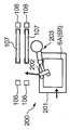
도 1은 본 발명에 의한, 고체 고분자막 연료 전지의 제조 프로세스를 설명하는 제조 장치의 개략 구성도이다.BRIEF DESCRIPTION OF THE DRAWINGS It is a schematic block diagram of the manufacturing apparatus explaining the manufacturing process of a solid polymer membrane fuel cell by this invention.
도 2는 세퍼레이터의 제조 장치로의 공급 구조를 설명하는, 공급 메커니즘의 개략 평면도이다.2 is a schematic plan view of a supply mechanism for explaining a supply structure to a manufacturing apparatus of a separator.
도 3은 본 발명에 의한 핫 프레스 공정을 설명하는 제조 장치의 개략 구성도이다.It is a schematic block diagram of the manufacturing apparatus explaining the hot press process by this invention.
도 4는 고체 고분자막 연료 전지와 가압 지그의 분해 종단면도이다.4 is an exploded longitudinal cross-sectional view of the solid polymer membrane fuel cell and the pressure jig.
도 5는 도 4와 유사하나, 가압 지그에 관한 다른 실시예를 도시한다.FIG. 5 is similar to FIG. 4 but shows another embodiment of the pressing jig.
도 6은 도 4와 유사하나, 가압 지그에 관한 또 다른 실시예를 도시한다.FIG. 6 is similar to FIG. 4 but shows another embodiment of the pressing jig.
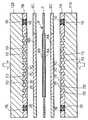
도면의 도 3을 참조하면, 고체 고분자막 연료 전지는 막전극 복합체(MEA)(9)와, 제1 가스 확산층(GDL)(6A)과, 제2 가스 확산층(GDL)(6B)과, 제1 세퍼레이터(7A)와 제2 세퍼레이터(7B)를, 한 쌍의 가압 지그(113, 123)를 이용하여 일체화함으로써 제조된다. MEA(9)와, 가스 확산층(6A, 6B)과, 세퍼레이터(7A, 7B)는 모두 직사각형의 평면 형상을 갖는다.Referring to FIG. 3 of the drawing, the solid polymer membrane fuel cell includes a membrane electrode composite (MEA) 9, a first gas diffusion layer (GDL) 6A, a second gas diffusion layer (GDL) 6B, and a first It is manufactured by integrating the
MEA(9)는 퍼플루오로에틸렌술폰산 수지막에 의한 고체 고분자막(5)의 양면에, 제1 촉매층(8A)과 제2 촉매층(8B)을 일정한 간격으로 형성한 것이다. 촉매층(8A, 8B)은 촉매로서의 백금을 포함하는 전해질액을, 미리 고체 고분자막(5)에 도포함으로써 형성된다.In the
촉매층(8A, 8B)의 한 쪽은 연료 전지의 애노드를, 다른 한 쪽은 연료 전지의 캐소드를 구성한다. 제1 촉매층(8A), 제1 GDL(6A) 및 제1 세퍼레이터(7A)는, 고체 고분자막(5)의 아래쪽에 배치되고, 제2 촉매층(8B), 제2 GDL(6B) 및 제2 세퍼레이터(7B)는 고체 고분자막(5)의 아래쪽에 배치된다. 가압 지그(123)는 아래쪽으로부터 제1 세퍼레이터(7A)에 접촉하고, 가압 지그(113)는 위쪽으로부터 제2 세퍼레이 터(7B)에 접촉한다.One of the
도 1에 도시하는 바와 같이, MEA(9)는 롤(100)로서 공급된다. 촉매층(8A, 8B)을 보호하기 위해서, MEA(9)는 보호 필름으로 표면을 덮은 상태로 롤에 감겨 있다.As shown in FIG. 1, the MEA 9 is supplied as a
GDL(6A, 6B)은, 카본 크로스(carbon cloth)나 카본 페이퍼를 발수 처리한 것으로, 세퍼레이터(7A, 7B)로부터 공급되는 애노드 가스와 캐소드 가스를 촉매층(8A, 8B)을 향하여 확산시키면서 침투시키는 역할을 갖는다. GDL(6A, 6B)은, 각각 전기적 절연 재료로 구성된 프레임(6C)의 내측에 미리 장착된 상태로 공급된다.The
제1 세퍼레이터(7A)는, 제1 GDL(6A)에 면하는 일면에 홈 형상의 가스 통로(7C)를 구비한다. 가스 통로(7C)로부터 가스가 누설되는 것을 방지하기 위해서, 제1 세퍼레이터(7A)에는, 시일용의 가스켓(10)을 충전하는 시일 홈(7E)이 외주를 따라서 형성되어 있다. 또한, 제1 세퍼레이터(7A)의 다른 한 쪽의 면에는, 홈 형상의 냉각액 통로(7D)와 시일용의 가스켓(10)을 충전하는 시일 홈(7E)이 형성되어 있다.The
제2 세퍼레이터(7B)는 제2 GDL(6B)에 면하는 일면에 홈 형상의 가스 통로(7C)를 구비한다. 가스 통로(7C)로부터 가스가 누설되는 것을 방지하기 위해서, 제2 세퍼레이터(7A)에는, 시일용의 가스켓(10)을 충전하는 시일 홈(7E)이 외주를 따라서 형성되어 있다. 제2 세퍼레이터(7B)의 다른 한 쪽의 면은 플랫하게 형성되어 있다.The
제1 세퍼레이터(7A)의 냉각액 통로(7D)는 제조하는 연료 전지의 사양에 의존 하며, 반드시 형성하지 않아도 된다. 그 경우에는, 제1 세퍼레이터(7B)를 세퍼레이터(7A)와 제2 세퍼레이터(7B)를 동일 사양으로 할 수 있다. 연료 전지의 사양에 따라서는, 냉각액 통로(7D) 대신에, 적층시에 인접하는 다른 연료 전지를 위한 가스 통로를 형성하는 것도 가능하다.The
세퍼레이터(7A, 7B)는, 그래파이트(graphite) 분말과 플라스틱 분말을 혼합하여 금형에 의한 가열 프레스에 의해 압축 성형함으로써 형성된다. 혹은, 팽창 흑연 시트를 프레스 성형하는 것에 의해서도 형성 가능하다. 또한, 금속을 이용하여 형성하는 것도 가능하다.The
세퍼레이터(7A, 7B)에 요망되는 특성은, 전기 저항이 작고 가스 투과성이 낮은 것이다. 또한, 세퍼레이터(7A, 7B)의 두께를 줄이기 위해서, 기계적 강도가 우수한 것이 바람직하다. 금속제의 세퍼레이터는 이러한 요구를 충족시킬 수 있지만, 세퍼레이터(7A, 7B)는 산화 분위기와 환원 분위기 양쪽에 노출되기 때문에, 내식성 금속을 이용하거나, 금속 도금에 의한 표면 처리를 실시하는 것이 바람직하다.The characteristics desired for the
도 1을 참조하면, 본 발명은, 이상과 같이 구성된 MEA(1)와 GDL(6A, 6B)과 세퍼레이터(7A, 7B)를, 가압 지그(113, 123)를 구비한 프레스기(101)를 이용하여 조립한다.Referring to FIG. 1, the present invention uses the
MEA(9)는 롤(100)로부터 반송 롤러(102), 벨트 컨베이어(103), 및 배출 롤러(104)로 이루어지는 반송 메커니즘에 의해서 대략 수평 방향으로 프레스기(101)를 향하여 송출된다. 바람직하게는, MEA(9)의 양 측부에 일정 간격으로 반송 구멍을 형성하고, 반송 롤러(102)와 배출 롤러(104)에 반송 구멍에 걸어 맞추는 돌기를, 동일한 각도 간격으로 형성해 놓는다. 이러한 구성에 의해, MEA(9)가 반송 도중에 느슨해지는 것을 방지하고, 촉매층(8)의 형성 간격에 맞추어 일정 길이씩, MEA(9)를 높은 정밀도로 프레스기(101)에 공급할 수 있다. 또한, MEA(9)에 촉매층(8A, 8B)의 위치에 대응한 마크를 붙이고, 프레스기(101)에 마크를 읽어내는 센서를 배치하는 것도 바람직하다. 센서가 읽어내는 마크에 기초하여 MEA(9)의 송출을 행함으로써, 프레스기(101) 내의 소정의 작업 위치에 촉매층(8A, 8B)을 정확히 배치할 수 있다.The MEA 9 is fed from the
MEA(9)의 표면을 덮는 보호 필름은, 롤(100)로부터 MEA(1)가 송출될 때에, 보호 필름 권취 롤러(105)에 의해서 권취된다.The protective film covering the surface of the MEA 9 is wound by the protective
제1 GDL(6A)은, 반송 롤러(106A), 벨트 컨베이어(107), 및 배출 롤러(108)로 이루어지는 반송 메커니즘에 의해, MEA(9)의 아래쪽을 통과하여 프레스기(101)에 공급된다. 제2 GDL(6B)는, 같은 구성에 의한 반송 메커니즘에 의해, MEA(9)의 위쪽을 통과하여 프레스기(101)에 공급된다.The
제1 GDL(6A)와 제2 GDL(6B)의 반송의 초기 위치는, 각각 반송 롤러(106)와 벨트 컨베이어(107)에 걸치는 위치이다. 이들 2개의 초기 위치에 GDL(6A, 6B)을 반입하는 것은 도 2에 도시하는 공급 메커니즘(200)에 의해서 행한다.The initial positions of conveyance of the
도 2를 참조하면, 공급 메커니즘(200)은 반송 롤러(106)와 벨트 컨베이어(107)의 옆쪽에 배치된다. 공급 메커니즘(200)은 반입 스테이지(201)와 로봇(203)을 구비한다. 로봇(203)은 선회식 로봇 아암(202)을 구비한다. 반입 스테이지(201) 상에 반입된 GDL(6A, 6B)은 선회식 로봇 아암(202)에 파지(把持)되어, 소기(所期) 위치에 세팅된다. 로봇(203)은 MEA(1)의 제1 GDL(6A)의 초기 위치와, 제2 GDL(6B)의 초기 위치의 쌍방에 GDL(6A, 6B)을 세팅 가능한 구조로 한다.Referring to FIG. 2, the
다시 도 1을 참조하면, 제1 세퍼레이터(7A)는, 반송 롤러(109)와, 벨트 컨베이어(110)와, 배출 롤러(111)로 이루어지는 반송 메커니즘에 의해서 프레스기(101)를 향하여 송출된다. 제2 세퍼레이터(7B)도 같은 구성에 의한 다른 반송 메커니즘에 의해서 프레스기(101)를 향하여 송출된다.Referring again to FIG. 1, the
제1 세퍼레이터(7A)의 반송 메커니즘은, 제1 GDL(6A)의 반송 메커니즘의 더 아래쪽에 배치된다. 제2 세퍼레이터(7B)의 반송 메커니즘은, 제2 GDL(6B)의 반송 메커니즘의 더 위쪽에 배치된다.The conveyance mechanism of the
제1 세퍼레이터(7A)와 제2 세퍼레이터(7B)의 반송의 초기 위치는, 각각 반송 롤러(109)와 벨트 컨베이어(110)에 걸치는 위치이다. 이들 2개의 초기 위치에 세퍼레이터(7A, 7B)를 반입하는 것은, GDL(6A, 6B)의 공급 메커니즘과 동일하게 구성된 공급 메커니즘에 의해 행한다. 세퍼레이터(7A, 7B)의 공급 메커니즘은 GDL(6A, 6B)의 공급 메커니즘과 간섭하지 않도록, 바람직하게는 반송 메커니즘을 사이에 두고 GDL(6A, 6B)의 공급 메커니즘과 반대측에 배치한다.The initial position of conveyance of the
이상의 구성에 의해, 프레스기(101)에는 제1 세퍼레이터(7A), 제1 GDL(6A), MEA(9), 제2 GDL(6B), 및 제2 세퍼레이터(7B)가 이 순서로 공급된다.By the above structure, the
프레스기(101)는, 승강 테이블(112)과, 그 위쪽에 고정된 지지구(120)로 이루어진다. 승강 테이블(112)은 제1 세퍼레이터(7A), 제1 GDL(6A), MEA(9), 제2 GDL(6B), 및 제2 세퍼레이터(7B)를 실어놓는 가압 지그(113)와, 가압 지그(113)를 지지하는 수직의 샤프트(113A)를 구비한다. 샤프트(113A)에는 랙(114)이 형성된다. 승강 테이블(112)은 랙(114)에 맞물리는 피니언(115)과, 피니언(115)을 회전 구동하는 서보 모터(116)와, 샤프트(113A)의 상하움직임을 안내하는 베어링(117)을 더 구비한다. 가압 지그(113)에는 히터(118)가 내장된다.The
지지구(120)는, 승강 테이블(112)이 밀어 올린 연료 전지의 구성 부재를 하향으로 지지하는 가압 지그(123)를 구비한다. 가압 지그(123)에는 히터(121)가 매설된다. MEA(9)의 반송 방향에 관해서, 지지구(120)의 전면과 배면에는, MEA(9)를 절단하는 한 쌍의 커터(122)가 장착된다.The
다음으로 도 3을 참조하여, 프레스기(101)에 의한 핫 프레스 공정을 설명한다.Next, with reference to FIG. 3, the hot press process by the
2매의 GDL(6A, 6B)의, MEA(9)에 상대하는 면에는, 한정된 소정 위치에 미리 페놀계 또는 에폭시계의 열경화 수지를 포함하는 접착제를 각각 도포하여 둔다. 접착제의 도포는 공급 메커니즘(200)에서 행하거나, 혹은 반송 메커니즘에 의한 GDL(6A, 6B)의 반송 과정에서 행한다.On the surface of the two
제2 GDL(6B)에 관해서는, 하면에 접착제를 도포하므로, 접착제의 도포 위치는 반송 롤러(102), 벨트 컨베이어(103), 및 배출 롤러(104)와 간섭하지 않는 위치로 설정한다.Regarding the
2매의 세퍼레이터(7A, 7B)의 GDL(6A, 6B)에 상대하는 면에는, 미리 페놀계 또는 에폭시계의 열경화 수지를 포함하는 접착제를 각각 도포해 놓는다. 구체적으 로는, 도 3에서, 세퍼레이터(7A, 7B)의 가스 통로(7C)의 사이에 위치하는 격벽부(7F)에 접착제를 도포해 둔다. 접착제의 도포는 세퍼레이터(7A, 7B)의 공급 메커니즘에서 행하거나 혹은, 반송 메커니즘에 의한 세퍼레이터(7A, 7B)의 반송 과정에서 행한다. 세퍼레이터(7A)에 관해서는 하면에 접착제를 도포하므로, 접착제의 도포 위치는 반송 롤러(109), 벨트 컨베이어(110) 및 배출 롤러(111)와 간섭하지 않는 위치로 설정한다.The adhesive agent containing the phenol type or epoxy type thermosetting resin is apply | coated previously to the surface which faces
핫 프레스는, MEA(9), GDL(6A, 6B) 및 세퍼레이터(7A, 7B)를 가열하면서 프레스함으로써, 이들 부재를 열 압착 또는 열 접착에 의해 일체화하는 공정이다.A hot press is a process of integrating these members by thermocompression bonding or thermal bonding by pressing while heating
각 반송 메커니즘이, 제1 세퍼레이터(7A), 제1 GDL(6A), MEA(9), 제2 GDL(6B) 및 제2 세퍼레이터(7B)를 이 순서로 가압 지그(113) 상에 적층한 후, 도 3에 도시하는 바와 같이 프레스기(101)는 서보 모터(116)의 운전에 의해 피니언(115)을 회전 구동하고, 랙(114)과 샤프트(113A)를 통해 가압 지그(113)를 지지구(120)를 향하여 밀어 올린다.Each conveyance mechanism laminated | stacked the
도 4를 참조하면, 가압 지그(113)의 상승에 의해, 적층체의 최상부에 위치하는 제2 세퍼레이터(7B)는, 지지구(120)의 가압 지그(123)에 접촉한다. 가압 지그(123)는 히터(121)에 의해서, 가압 지그(113)는 히터(118)에 의해서, 미리 각각 섭씨 80도 내지 150도의 범위로 가열해 놓는다. 또한, 도면에서는 설명을 위해, MEA(9), GDL(6A, 6B) 및 세퍼레이터(7A, 7B)가 각각 서로 격리되어 있지만, 실제로 가압 지그(113)가 상승하는 경우에는, 이들 부재는 적층된 상태로 상승한다.Referring to FIG. 4, with the rising of the
제2 세퍼레이터(7B)가 가압 지그(123)에 접촉한 후, 가압 지그(113)는 가압 지그(123)와의 사이에서 적층 상태의 MEA(9), GDL(6A, 6B) 및 세퍼레이터(7A, 7B)에 상하 방향으로부터 소정의 압력과 열을 가한다. 그 결과, GDL(6A, 6B)에 도포한 접착제가 MEA(9)와 열 접착한다. 구체적으로는, 접착제에 포함되는 열경화제가 가열에 의해 경화함으로써, MEA(9)와 GDL(6A, 6B)을 강고하게 접착한다. After the
접착제는 전술과 같이 DGL(6A, 6B)의 전체면이 아니라, 한정된 장소에만 도포되어 있다. 따라서, 완성 후의 연료 전지에서, GDL(6A, 6B)로부터 촉매층(8A, 8B)으로 가스가 확산하고 침투하는 것은, 접착제에 저해되는 일없이 행하여진다. 접착제를 도포하지 않는 면에 대해서도, 촉매층(8A, 8B)을 구성하는 전해질이 GDL(6A, 6B)에 열 압착하여, 앵커(anchor) 효과로 GDL(6A, 6B)과 촉매층(8A, 8B)을 간극없이 밀착시킨다.As described above, the adhesive is applied only to a limited place, not to the entire surface of the
또한, 세퍼레이터(7A, 7B)의 격벽부(7F)에 도포한 접착제도, 열경화제의 경화에 의해서, 세퍼레이터(7A, 7B)와 GDL(6A, 6B)을 강고하게 접착한다.Moreover, the adhesive agent apply | coated to the
이와 같이 하여, 제1 세퍼레이터(7A), 제1 GDL(6A), MEA(9), 제2 GDL(6B) 및 제2 세퍼레이터(7A)의 순서로 적층된 적층체는, 한번의 핫 프레스 공정에 의해 일체화되어, 단시간에 연료 전지를 완성한다.Thus, the laminated body laminated | stacked in order of the
프레스기(101)에서 일체화된 연료 전지는, 도 1과 도 3에 도시하는, 로봇 아암(301)을 구비한 로봇(300)에 의해 집적 장소로 반출된다.The fuel cell integrated in the
이후에는 다시, 각 공급 메커니즘과 반송 메커니즘에 의한, 세퍼레이터(7A), GDL(6A), MEA(9), GDL(6B) 및 세퍼레이터(7B)의 프레스기(101)에의 공급과, 프레스기(101)에 의한 이들 부재의 일체화와, 일체화된 연료 전지의 로봇(300)에 의한 집 적 장소로의 반출이 반복하여 행하여진다.Subsequently, the supply of the
이상과 같이, 본 발명은, 세퍼레이터(7A), GDL(6A), MEA(9), GDL(6B) 및 세퍼레이터(7B)를 한번의 핫 프레스 공정으로 일체화하므로, 고체 고분자막 연료 전지의 제조 프로세스를 단축할 수 있다.As described above, the present invention integrates the
이상의 실시예에서는, 고체 고분자막(5)의 양면에 촉매층(8A, 8B)을 일정 간격으로 코팅한 MEA(9)를 이용하고 있으나, 촉매층(8A, 8B)을 GDL(6A, 6B)의 표면에 형성하는 것도 가능하다. 이 경우에는, 반송 롤러(102), 벨트 컨베이어(103), 및 배출 롤러(104)로 이루어지는 반송 메커니즘이 단체(單體)의 고체 고분자막(5)을 프레스기(101)에 공급한다. 한편, GDL(6A, 6B)의 공급 메커니즘(200)은, GDL(6A, 6B)의 고체 고분자막(5)에 면하는 면에 촉매층(8A, 8B)을 도포한 후에, GDL(6A, 6B)을 반송 초기 위치에 공급한다. 이 경우에는, 프레스기(101)에서의 핫 프레스에 의해 촉매층(8A, 8B)을 고체 고분자막(5)에 열 압착시킨다. 고체 고분자막(5)의 반송 공정에서 촉매층(8A, 8B)을 고체 고분자막(5)의 소정 위치에 도포하는 것도 가능하다.In the above embodiment, the
본 발명에 의한 연료 전지의 제조 방법의 주제는 프레스기(101)에 의한 핫 프레스이고, 프레스기(101)에 부재를 공급하는 것이나, 일체화된 연료 전지를 반출하는 것에 관해서는, 어떠한 방법을 이용하여도 좋다.The subject of the fuel cell manufacturing method according to the present invention is a hot press by the
다음으로 도 5를 참조하여, 프레스기(101)의 가압 지그(113)의 형상에 관한 본 발명의 제2 실시예를 설명한다.Next, with reference to FIG. 5, the 2nd Embodiment of this invention regarding the shape of the
이 실시예는, 가압 지그(113)의 상면의 형상에 특징을 지닌다. 여기에서는, 가압 지그(113)의 상면을 평면으로 형성하는 대신에, 제1 세퍼레이터(7A)에 형성된 홈 형상의 냉각액 통로(7D)에 끼워 맞추는 상향의 띠 형상 돌기(13)를 형성하고 있다. 가압 지그(113)에 이러한 띠 형상 돌기(13)를 형성함으로써, 세퍼레이터(7A)의 위치 결정이 정확하게 행하여진다. 또한, 세퍼레이터(7A)를 흑연으로 형성할 때에는, 흑연이 무르기 때문에, 프레스기(101)가 적층체에 충분한 압축력을 가하기 어렵다. 이 실시예와 같이, 가압 지그(113)의 띠 형상 돌기(13)가 세퍼레이터(7A)의 홈 형상의 냉각 통로(7D)에 끼워 맞춰져서, 응력의 집중을 회피하면서, 충분한 압축력을 적층체에 가할 수 있다.This embodiment is characterized by the shape of the upper surface of the
다음으로 도 6을 참조하여, 프레스기(101)의 가압 지그(123)의 형상에 관한 본 발명의 제3 실시예를 설명한다.Next, with reference to FIG. 6, the 3rd Embodiment of this invention regarding the shape of the
이 실시예에서는, 제2 세퍼레이터(7B)의 배면에도 냉각액 통로(7D)를 형성하는 동시에, 제2 실시예의 띠 형상 돌기(13)를 가압 지그(113)의 상면과, 가압 지그(123)의 하면에 각각 형성한다.In this embodiment, the
이 실시예에 의하면, 세퍼레이터(7A, 7B)가 가압 지그(113)와 가압 지그(123)에 각각 간극없이 접하기 때문에, 핫 프레스에서의 세퍼레이터(7A, 7B)의 지지 구조가 한층 더 안정된다.According to this embodiment, since the
또한, 제2 실시예와 제3 실시예는, 냉각액 통로(7D) 대신에 가스 통로를 형성한 세퍼레이터에도 적용 가능하다.The second embodiment and the third embodiment are also applicable to a separator in which a gas passage is formed instead of the cooling
2004년 1월 28일을 출원일로 하는 일본에서의 특허출원 2004-019743호의 내용을 여기에 인용에 의해 합체한다.The content of patent application 2004-019743 in Japan which makes a January 28, 2004 filing date is hereby incorporated by reference.
이상과 같이, 본 발명을 몇 개의 특정한 실시예를 통하여 설명하였으나, 본 발명은 상기의 각 실시예로 한정되는 것이 아니다. 당업자에게는, 특허청구범위의 기술 범위에서 이러한 실시예에 여러가지 수정 혹은 변경을 가하는 것이 가능하다.As mentioned above, although this invention was demonstrated through several specific Example, this invention is not limited to each said Example. Those skilled in the art can make various modifications or changes to these embodiments within the scope of the claims.
본 발명에 의하면, 적층한 연료 전지의 구성 부재를 한번의 핫 프레스로 일체화할 수 있다. 따라서, 고체 고분자형 연료 전지 단체(單體)의 제조 프로세스를 단축할 수 있는 동시에, 수많은 연료 전지를 이용한 연료 전지 스택의 제조 프로세스의 일환으로서 본 발명을 받아들임으로써 특히 바람직한 효과를 얻을 수 있다.According to the present invention, the constituent members of the stacked fuel cells can be integrated in one hot press. Therefore, the manufacturing process of the solid polymer fuel cell alone can be shortened, and the present invention can be particularly advantageous by adopting the present invention as part of the manufacturing process of the fuel cell stack using a large number of fuel cells.
본 발명의 실시예가 포함하는 배타적 성질 혹은 특징은 이하와 같이 특허청구된다.Exclusive properties or features included in the embodiments of the present invention are claimed as follows.
Claims (7)
Translated fromKoreanApplications Claiming Priority (2)
| Application Number | Priority Date | Filing Date | Title |
|---|---|---|---|
| JP2004019743AJP2005216598A (en) | 2004-01-28 | 2004-01-28 | Solid polymer membrane fuel cell and method for producing the same |
| JPJP-P-2004-00019743 | 2004-01-28 |
Publications (2)
| Publication Number | Publication Date |
|---|---|
| KR20070001104Atrue KR20070001104A (en) | 2007-01-03 |
| KR100737660B1 KR100737660B1 (en) | 2007-07-09 |
Family
ID=34823729
Family Applications (1)
| Application Number | Title | Priority Date | Filing Date |
|---|---|---|---|
| KR1020067015070AExpired - Fee RelatedKR100737660B1 (en) | 2004-01-28 | 2004-12-28 | Solid polymer membrane fuel cell manufacturing method |
Country Status (5)
| Country | Link |
|---|---|
| JP (1) | JP2005216598A (en) |
| KR (1) | KR100737660B1 (en) |
| CN (1) | CN1906787A (en) |
| DE (1) | DE112004002695T5 (en) |
| WO (1) | WO2005074061A1 (en) |
Cited By (3)
| Publication number | Priority date | Publication date | Assignee | Title |
|---|---|---|---|---|
| KR100957370B1 (en)* | 2008-04-29 | 2010-05-11 | 현대자동차주식회사 | MG Automatic Assembly Device and Method |
| KR100957366B1 (en)* | 2008-03-13 | 2010-05-12 | 현대자동차주식회사 | Jig device for joining equipment for fuel cell stack separator |
| US8110850B2 (en) | 2008-12-26 | 2012-02-07 | Lg Innotek Co., Ltd | Semiconductor light emitting device |
Families Citing this family (9)
| Publication number | Priority date | Publication date | Assignee | Title |
|---|---|---|---|---|
| US7651581B2 (en)* | 2005-12-20 | 2010-01-26 | Gm Global Technology Operations, Inc. | Catalyst coated diffusion media |
| US8431284B2 (en) | 2007-06-26 | 2013-04-30 | GM Global Technology Operations LLC | Low electrical resistance bipolar plate-diffusion media assembly |
| JP5348388B2 (en)* | 2008-11-12 | 2013-11-20 | トヨタ自動車株式会社 | Manufacturing method of fuel cell |
| GB201207759D0 (en) | 2012-05-03 | 2012-06-13 | Imp Innovations Ltd | Fuel cell |
| KR101703617B1 (en)* | 2015-09-03 | 2017-02-07 | 현대자동차 주식회사 | Heat treatment device of mea for fuel cell |
| FR3062960B1 (en) | 2017-02-10 | 2021-05-21 | Commissariat Energie Atomique | FUEL CELL |
| FR3062958B1 (en)* | 2017-02-10 | 2019-04-05 | Commissariat A L'energie Atomique Et Aux Energies Alternatives | ELEMENTARY MODULE OF A FUEL CELL |
| JP6926999B2 (en)* | 2017-12-05 | 2021-08-25 | トヨタ自動車株式会社 | How to manufacture fuel cell |
| CN113728478B (en)* | 2019-09-09 | 2024-05-28 | Nok株式会社 | Sealing structure of separator for fuel cell unit |
Family Cites Families (3)
| Publication number | Priority date | Publication date | Assignee | Title |
|---|---|---|---|---|
| JPH0878028A (en)* | 1994-08-31 | 1996-03-22 | Aqueous Res:Kk | Solid polymer electrolyte fuel cell and method of manufacturing the same |
| JP2001236971A (en)* | 2000-02-24 | 2001-08-31 | Fuji Electric Co Ltd | Method for manufacturing polymer electrolyte fuel cell |
| JP3609016B2 (en)* | 2000-10-18 | 2005-01-12 | 本田技研工業株式会社 | Fuel cell seal mounting method and fuel cell |
- 2004
- 2004-01-28JPJP2004019743Apatent/JP2005216598A/ennot_activeWithdrawn
- 2004-12-28KRKR1020067015070Apatent/KR100737660B1/ennot_activeExpired - Fee Related
- 2004-12-28DEDE112004002695Tpatent/DE112004002695T5/ennot_activeWithdrawn
- 2004-12-28CNCNA2004800405765Apatent/CN1906787A/enactivePending
- 2004-12-28WOPCT/JP2004/019845patent/WO2005074061A1/ennot_activeCeased
Cited By (3)
| Publication number | Priority date | Publication date | Assignee | Title |
|---|---|---|---|---|
| KR100957366B1 (en)* | 2008-03-13 | 2010-05-12 | 현대자동차주식회사 | Jig device for joining equipment for fuel cell stack separator |
| KR100957370B1 (en)* | 2008-04-29 | 2010-05-11 | 현대자동차주식회사 | MG Automatic Assembly Device and Method |
| US8110850B2 (en) | 2008-12-26 | 2012-02-07 | Lg Innotek Co., Ltd | Semiconductor light emitting device |
Also Published As
| Publication number | Publication date |
|---|---|
| DE112004002695T5 (en) | 2007-09-13 |
| CN1906787A (en) | 2007-01-31 |
| JP2005216598A (en) | 2005-08-11 |
| WO2005074061A1 (en) | 2005-08-11 |
| KR100737660B1 (en) | 2007-07-09 |
Similar Documents
| Publication | Publication Date | Title |
|---|---|---|
| KR100737660B1 (en) | Solid polymer membrane fuel cell manufacturing method | |
| CN101523647B (en) | Membrane electrode assembly, method for producing the same, and solid polymer fuel cell using the same | |
| JP6056964B2 (en) | Fuel cell manufacturing method and manufacturing apparatus | |
| US9130206B2 (en) | Method for manufacturing resin-framed membrane electrode assembly for fuel cell | |
| CN101632192A (en) | Membrane-membrane reinforcement member assembly, membrane-catalyst layer assembly, membrane-electrode assembly, polymer electrolyte fuel cell, and method for manufacturing membrane-electrode assembly | |
| KR20060108667A (en) | Manufacture of fuel cells and fuel cell stacks | |
| US20210288338A1 (en) | Fuel cell and method for producing fuel cell | |
| JP2010027234A (en) | Fuel battery, and manufacturing method of electrode body of fuel battery cell | |
| JP2004303627A (en) | Method for producing electrolyte membrane-electrode laminate for direct methanol fuel cell | |
| US7681304B2 (en) | Membrane electrode assembly and method of manufacturing a membrane electrode assembly | |
| JP2008052953A (en) | Manufacturing method of fuel cell components | |
| TW201143195A (en) | Laminated fuel cell assembly | |
| JP4736787B2 (en) | Membrane electrode assembly and method for producing reinforced electrolyte membrane in polymer electrolyte fuel cell | |
| US20070154628A1 (en) | Solid polymer membrane fuel-cell manufacturing method | |
| JP2005332697A (en) | Method and apparatus for manufacturing fuel cell stack | |
| KR20210026928A (en) | Apparatus for manufacturing an elastomeric cell frame for fuel cell | |
| JP6221680B2 (en) | Manufacturing method of fuel cell | |
| JP4417135B2 (en) | Fuel cell | |
| JP4438327B2 (en) | GAS DIFFUSION LAYER MEMBER FOR SOLID POLYMER FUEL CELL AND METHOD FOR PRODUCING GAS DIFFUSION LAYER MEMBER | |
| KR100957370B1 (en) | MG Automatic Assembly Device and Method | |
| US20250309285A1 (en) | Manufacturing method and manufacturing apparatus of fuel cell membrane electrode structure | |
| US20130309594A1 (en) | Methods for making a thermoformed subgasket and products thereof | |
| KR20090036290A (en) | Ultrasonic welding device for joining metal separator plate of fuel cell | |
| JP2016012435A (en) | Manufacturing method of fuel cell | |
| JP2009080976A (en) | Fuel cell single cell sealing method |
Legal Events
| Date | Code | Title | Description |
|---|---|---|---|
| A201 | Request for examination | ||
| PA0105 | International application | St.27 status event code:A-0-1-A10-A15-nap-PA0105 | |
| PA0201 | Request for examination | St.27 status event code:A-1-2-D10-D11-exm-PA0201 | |
| P11-X000 | Amendment of application requested | St.27 status event code:A-2-2-P10-P11-nap-X000 | |
| P13-X000 | Application amended | St.27 status event code:A-2-2-P10-P13-nap-X000 | |
| P11-X000 | Amendment of application requested | St.27 status event code:A-2-2-P10-P11-nap-X000 | |
| P13-X000 | Application amended | St.27 status event code:A-2-2-P10-P13-nap-X000 | |
| R15-X000 | Change to inventor requested | St.27 status event code:A-3-3-R10-R15-oth-X000 | |
| R16-X000 | Change to inventor recorded | St.27 status event code:A-3-3-R10-R16-oth-X000 | |
| PG1501 | Laying open of application | St.27 status event code:A-1-1-Q10-Q12-nap-PG1501 | |
| E701 | Decision to grant or registration of patent right | ||
| PE0701 | Decision of registration | St.27 status event code:A-1-2-D10-D22-exm-PE0701 | |
| GRNT | Written decision to grant | ||
| PR0701 | Registration of establishment | St.27 status event code:A-2-4-F10-F11-exm-PR0701 | |
| PR1002 | Payment of registration fee | St.27 status event code:A-2-2-U10-U12-oth-PR1002 Fee payment year number:1 | |
| PG1601 | Publication of registration | St.27 status event code:A-4-4-Q10-Q13-nap-PG1601 | |
| PN2301 | Change of applicant | St.27 status event code:A-5-5-R10-R13-asn-PN2301 St.27 status event code:A-5-5-R10-R11-asn-PN2301 | |
| LAPS | Lapse due to unpaid annual fee | ||
| PC1903 | Unpaid annual fee | St.27 status event code:A-4-4-U10-U13-oth-PC1903 Not in force date:20100704 Payment event data comment text:Termination Category : DEFAULT_OF_REGISTRATION_FEE | |
| PC1903 | Unpaid annual fee | St.27 status event code:N-4-6-H10-H13-oth-PC1903 Ip right cessation event data comment text:Termination Category : DEFAULT_OF_REGISTRATION_FEE Not in force date:20100704 |