KR20060136383A - Nonwoven elastic fibrous webs and methods for making them - Google Patents
Nonwoven elastic fibrous webs and methods for making themDownload PDFInfo
- Publication number
- KR20060136383A KR20060136383AKR1020067011900AKR20067011900AKR20060136383AKR 20060136383 AKR20060136383 AKR 20060136383AKR 1020067011900 AKR1020067011900 AKR 1020067011900AKR 20067011900 AKR20067011900 AKR 20067011900AKR 20060136383 AKR20060136383 AKR 20060136383A
- Authority
- KR
- South Korea
- Prior art keywords
- fibers
- filaments
- web
- fiber
- temperature
- Prior art date
- Legal status (The legal status is an assumption and is not a legal conclusion. Google has not performed a legal analysis and makes no representation as to the accuracy of the status listed.)
- Withdrawn
Links
Images


Abstract
Translated fromKoreanDescription
Translated fromKorean본 발명은 탄성 섬유를 포함하고, 이에 의해 웹이 전체적으로 탄성을 가질 수 있는 부직 섬유 웹에 관한 것이다.The present invention relates to a nonwoven fibrous web comprising elastic fibers, whereby the web can be elastic in its entirety.
중요한 상업적 기회는 적합하게 신축성이고 탄성이고 강한 부직 섬유 웹을 기대하고 있다. 이러한 웹은 가먼트 형태-맞음새를 이루거나, 또는 탄성적으로 그의 형태를 보유하는 가먼트의 커프, 넥-라인 또는 다른 부분을 만드는데 유용할 수 있다. 또는, 이러한 웹은 통기성이고, 부드러우며, 경량이고, 순면감촉인 직물을 제공할 수 있다. 또한, 이러한 웹은 높은 마찰력을 갖는 것이기 쉽고, 많은 분야에서 유용할 수 있다.An important commercial opportunity is expected for suitably stretchable, elastic and strong nonwoven fibrous webs. Such a web may be useful for making a cuff, neck-line, or other portion of a garment that forms a garment shape-fit, or elastically retains its shape. Alternatively, such webs can provide a breathable, soft, lightweight, cottony fabric. In addition, such webs are likely to have high friction and may be useful in many fields.
이러한 기회를 인식하여, 많은 선행 기술자들이 탄성 부직 섬유 웹을 제조하고자 하였다. 이들의 선행 작업은 미국 특허 제3,686,385호; 제4,707,398호; 제4,707,398호; 제4,820,572호; 제4,891,957호; 제5,322,728호; 제5,366,793호; 제5,470,639호; 및 제5,997,989호를 포함하는 특허 문헌에 나타나 있다.Recognizing this opportunity, many prior art engineers have attempted to produce elastic nonwoven fibrous webs. Their prior work is described in US Pat. No. 3,686,385; No. 4,707,398; No. 4,707,398; 4,820,572; 4,891,957; 5,322,728; 5,322,728; 5,366,793; 5,366,793; No. 5,470,639; And 5,997,989.
선행 작업이 일부 요구사항들을 만족시켰을 수는 있지만, 많은 기회들이 만족스럽지 못하게 남아있다. 일반적으로, 선행 업적들은 가시화된 기회들 중 다수 를 수행할 수 있는 신축성, 탄성, 결합성 및 강도의 적절한 조합을 갖는 섬유 웹을 제조하지 못하였다.Although predecessors may have met some requirements, many opportunities remain unsatisfactory. In general, previous achievements have not produced a fibrous web with a suitable combination of elasticity, elasticity, bondability, and strength that can carry out many of the visible opportunities.
<발명의 요약>Summary of the Invention
본 발명은 배향되어 있는 직접적으로 수집된 탄성 섬유들을 포함하는 섬유 탄성 부직 웹을 제공하여, 유리한 및 우수한 강도 특성을 갖는 섬유 및 웹을 제공한다.The present invention provides a fibrous elastic nonwoven web comprising directly collected elastic fibers that are oriented, thereby providing fibers and webs with advantageous and good strength properties.
"직접 형성된 섬유"는 본질적으로 한번의 작업으로, 예를 들면 섬유-형성 액체로부터 필라멘트를 압출하고, 압출된 필라멘트들을 이들이 수집기로 이동할 때 고화된 섬유 형태로 가공하고, 및 섬유들이 액체 형태를 떠난 후 수초 이내에 웹으로서 가공된 섬유를 수집함으로써 섬유 부직 웹으로 형성되고 수집된 섬유를 의미한다. 이러한 방법은 예를 들면, 압출된 섬유들이 웹으로 결집되기 전에 스테이플 섬유로 세단되는 방법과 대조적이다. 스펀본드 섬유 및, 미국 특허 제6,607,624호에 기재된 방식으로 웹으로 제조되고 수집된 섬유를 포함하는 멜트블로운 섬유 및 멜트스펀 섬유가 본 발명에 유용한 직접 형성된 섬유의 예이다.“Directly formed fibers” are essentially one operation, for example, extrude filaments from a fiber-forming liquid, process the extruded filaments into solidified fiber form as they move to the collector, and the fibers leave the liquid form. By fibers collected within a few seconds after being processed as a web means a fiber formed and collected into a fiber nonwoven web. This method is in contrast to, for example, the method in which the extruded fibers are shredded into staple fibers before they are aggregated into the web. Meltblown fibers and meltspun fibers, including spunbond fibers and fibers made and collected from the web in the manner described in US Pat. No. 6,607,624 are examples of directly formed fibers useful in the present invention.
"배향된"이란, 섬유들 내의 중합체 분자 부분들이 섬유의 길이방향으로 정렬되어 고착되는, 즉 열적으로 고정되거나 또는 그 정렬 내에 갇히는 것을 의미한다. 달리 말하면, 분자들이 그들의 배향으로부터 벗어나서 움직이기 위하여, 정렬은 분자들이 자유로이 이동하여 그들의 배향을 상실하기에 충분하게 그들 자신을 재배치하기에 충분한 시간 동안 섬유에 대한 이완 온도 이상으로 섬유를 가열할 필요가 있다["이완 온도"는 본원에서 유리 전이 온도(무정형 비결정질 물질의 경우) 또는 용융 온도(결정질 또는 반결정질 물질의 경우)의 ±5 ℃ 이내인 온도로서 정의된다]. 정렬된 분자들은 섬유의 개선된 강도 특성을 가질 수 있다.By "oriented" is meant that the polymer molecular portions in the fibers are aligned and fixed in the longitudinal direction of the fiber, ie thermally fixed or trapped within the alignment. In other words, in order for the molecules to move out of their orientation, the alignment needs to heat the fibers above the relaxation temperature for the fibers for a time sufficient for the molecules to move freely and reposition themselves sufficiently to lose their orientation. Is defined herein as the temperature within ± 5 ° C. of the glass transition temperature (for amorphous amorphous materials) or the melting temperature (for crystalline or semicrystalline materials). The aligned molecules can have improved strength properties of the fiber.
분자들이 한 섬유 내에서 배향되어 있는지 여부는 일반적으로 섬유가 복굴절을 나타내는지를 측정함으로써 나타날 수 있다. 섬유가 본원에 기재된 시험에 의해 약 1 x 10⁻⁵ 이상의 복굴절 값을 나타내는 경우, 이들은 배향된 것으로 간주된다. 복굴절 값이 더 높을수록, 배향도는 더 높고, 바람직하게는 본 발명의 웹 중의 섬유는 1 x 10⁻⁴ 이상 또는 1 x 10⁻³ 이상의 복굴절 값을 나타내고, 특정 중합체의 경우, 본 발명자들은 1 x 10⁻² 이상의 복굴절 값을 갖는 섬유들을 성공적으로 제조하였다. 상이한 중합체 군들로 된 섬유들은 상이한 배향도 및 상이한 정도의 복굴절값을 나타낼 수 있다.Whether molecules are oriented in one fiber can generally be seen by measuring whether the fiber exhibits birefringence. If the fibers exhibit birefringence values of at least about 1 × 10⁻⁵ by the tests described herein, they are considered oriented. The higher the birefringence value, the higher the degree of orientation, preferably the fibers in the web of the invention exhibit birefringence values of at least 1 × 10⁻⁴ or at least 1 × 10⁻³ , and for certain polymers, the inventors have 1 × Fibers with birefringence values of at least 10−2 have been successfully produced. Fibers of different polymer groups can exhibit different degrees of orientation and different degrees of birefringence.
직접 형성된 배향된 섬유들은 변하는 탄성도를 가질 수 있지만, 바람직하게는 이들은 "엘라스토머성" 섬유이다. 용어 "엘라스토머성 섬유"는 본원에서 그들의 원래의 길이의 2배 이상으로 신축될 수 있고, 이들을 그들의 원래의 길이의 2배로 신축시키는 인장으로부터 해제될 때, 즉시 그들의 원래의 길이의 1¼ 이하로 수축하게 되는 섬유를 의미하는 것으로 간주된다. 엘라스토머성 섬유는 특히 특정 용도에 필요하고, 배향된 엘라스토머성 섬유는 신축성이 적거나 또는 탄성 회복이 적은 탄성 섬유는 제공할 수 없는 명백한 기여를 한다. 용어 "탄성 섬유"는 본원에서 보다 적은 신축성을 갖지만, 그들의 신축된 치수로부터 적어도 부분적으로 탄성적으로 회복하는 섬유를 포함하여 보다 큰 범주의 섬유들을 설명하는 것으로 간 주된다. 탄성 섬유는 일반적으로 본원에서 파단 전에 그의 원래의 길이의 125% 이상으로 신축될 수 있고, 인장의 해제시에 이러한 신축도로부터 신장율의 양의 50% 이상을 수축하게 되는 것으로 간주된다.Directly formed oriented fibers can have varying degrees of elasticity, but preferably they are "elastomeric" fibers. The term "elastomeric fibers" herein can be stretched to at least twice their original length, and upon release from the tension that stretches them to twice their original length, they immediately shrink to less than 1¼ of their original length. It is considered to mean fibers. Elastomeric fibers are particularly needed for certain applications, and oriented elastomeric fibers make an obvious contribution that elastic fibers with less stretch or less elastic recovery cannot provide. The term "elastic fiber" is considered herein to describe a larger category of fibers, including fibers that have less elasticity, but at least partially elastically recover from their stretched dimensions. Elastic fibers are generally considered herein to be stretched to at least 125% of their original length prior to fracture and to shrink at least 50% of the amount of elongation from this stretch upon release of tension.
배향된 섬유를 갖지만, 본 발명의 웹은 치수 안정성일 수 있으며, 바람직하게는 치수 안정성이다. "치수 안정성"이란, 70℃의 온도로 가열될 때 웹이 그의 폭 치수(웹이 수집되는 수집기의 이동 방향인, 기계 방향에 대해 횡방향)가 약 10% 이하만큼 수축하게 되는 것을 의미한다. 본 발명자들은 그렇게 하지 않을 경우 가열시 웹이 수축될 수 있게 하는 변형을 해제시키기 위해 어닐링될 수 있고, 어닐링에도 불구하고, 섬유들은 개선된 특성을 제공하는 보유된 배향을 가질 수 있다.Although having oriented fibers, the web of the present invention may be dimensional stability, preferably dimensional stability. "Dimensional stability" means that when heated to a temperature of 70 ° C, the web shrinks by about 10% or less in its width dimension (transverse to the machine direction, the direction of movement of the collector from which the web is collected). We can anneal to release the strain that would otherwise cause the web to shrink upon heating, and despite the annealing, the fibers can have a retained orientation that provides improved properties.
본 발명은 또한 간략히 요약하면, a) 탄성 섬유-형성 물질의 필라멘트를 압출시키는 단계; b) 필라멘트를, 필라멘트를 섬세화하고 연신시키는 길이방향 응력이 필라멘트에 인가되는 가공 챔버를 지나게 보내는 단계; c) 필라멘트 내의 분자들이 필라멘트의 길이를 따라 배향되기에 충분한 시간 동안 필라멘트들이 섬세화 및 연신시키는 응력 하에 있는 동안에 필라멘트들을 그들의 배향 온도로 유지시키는 단계; d) 필라멘트들이 섬세화 및 연신시키는 응력 하에 있는 동안에 필라멘트들을 그들의 배향-고착 온도로 냉각시키고, 필라멘트들을 고화된 탄성 섬유로 추가로 냉각시키는 단계; 및 e) 고화된 탄성 섬유들을 섬유 부직 웹으로서 수집하는 단계를 포함하는 본 발명의 탄성 섬유 및 웹의 새로운 제조 방법을 제공한다.The invention also briefly summarizes: a) extruding a filament of an elastic fiber-forming material; b) passing the filament past a processing chamber in which longitudinal stresses are applied to the filament to refine and draw the filament; c) maintaining the filaments at their orientation temperature while the filaments are under stress to refine and elongate for sufficient time for the molecules in the filaments to be oriented along the length of the filament; d) cooling the filaments to their orientation-fixing temperature and further cooling the filaments with the solidified elastic fibers while the filaments are under stress to refine and elongate; And e) collecting the solidified elastic fibers as a fibrous nonwoven web.
"배향 온도"는 압출된 필라멘트들 내의 분자들이 섬세화 또는 연신시키는 응력 하에 필라멘트들의 길이방향으로의 정렬로 이동할 수 있는 온도를 의미하고; 이 온도는 일반적으로 필라멘트의 경우 적어도 대략 융점(Tm) 또는 유리 전이점(Tg)이거나 또는 이보다 더 크다. "배향-고착 온도"는 필라멘트들의 분자들이 이들이 필라멘트 내에서 얻었을 수 있었던 배향으로 열적으로 고정되거나 또는 갇히게 되는 온도를 의미한다. 이 온도는 일반적으로 필라멘트의 경우 이완 온도보다 약 30 ℃ 이상 미만이다."Orientation temperature" means the temperature at which molecules in the extruded filaments can move in the longitudinal alignment of the filaments under stresses that soften or elongate; This temperature is generally at least about melting point (Tm ) or glass transition point (Tg ) or greater for filaments. "Orientation-fixing temperature" means the temperature at which molecules of the filaments are thermally fixed or trapped in an orientation that they could have obtained within the filament. This temperature is generally about 30 ° C. or more below the relaxation temperature for filaments.
본 발명의 다른 면에서, 기재된 방법은 제조된 섬유들을 섬유의 수축 온도 이상이지만 섬유의 이완 온도보다 10 ℃ 미만인 온도에 노출시킴으로써 어닐링시키는 추가의 단계를 포함한다("수축 온도"는 본원에서 10% 초과의 수축에 의해 섬유가 변형을 해제시키지만, 섬유의 융점 또는 연화 온도 미만인 온도이다). 본 발명자들은 이러한 단계 동안에 본 발명에 따라 제조된 바람직한 섬유들이 어느 정도의 유용한 분자 배향을 유지하면서 수축을 행할 수 있음을 발견하였다. 그리고, 섬유 및 웹의 탄성 특성, 특히 이들의 신축성의 양은 어닐링에 의해 및 어닐링과 함께 일어나는 수축에 의해 증가될 수 있다.In another aspect of the invention, the described method includes an additional step of annealing the fibers produced by exposure to a temperature above the shrinkage temperature of the fiber but below 10 ° C. below the fiber's relaxation temperature (“shrinkage temperature” herein is 10% Excess shrinkage causes the fiber to release strain, but below the melting point or softening temperature of the fiber). The inventors have found that during this step the preferred fibers made according to the invention can shrink while maintaining some useful molecular orientation. And the elastic properties of the fibers and webs, especially their stretch, can be increased by annealing and by shrinkage that occurs with the annealing.
도 1은 본 발명의 부직 섬유 웹을 형성하는데 유용한 장치의 전체 개략도이다.1 is an overall schematic view of an apparatus useful for forming the nonwoven fibrous web of the present invention.
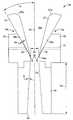
도 2는 챔버용 탑재 수단이 나타나있지 않는, 본 발명의 부직 섬유 웹을 형성하는데 유용한 가공 챔버의 확대 측면도이다.2 is an enlarged side view of a processing chamber useful for forming the nonwoven fibrous web of the present invention, in which mounting means for the chamber are not shown.
도 3은 탑재 및 다른 관련 장치와 함께 도 2에 나타낸 가공 챔버의 부분 개 략적 상부도이다.3 is a partial schematic top view of the processing chamber shown in FIG. 2 together with mountings and other related devices.
도 4a, 4b 및 4c는 본 발명의 웹 내 예시적인 섬유 결합을 관통하는 개략도이다.4A, 4B and 4C are schematic views through exemplary fiber bonds in the web of the present invention.
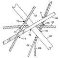
도 5는 서로 교차하고 서로에 결합된 섬유들을 나타내는, 본 발명의 웹의 일부분에 대한 개략도이다.5 is a schematic diagram of a portion of the web of the present invention, showing fibers intersecting with and bonded to each other.
도 6 및 7은 수반되는 예시적인 장치 및 설명적 정보가 있는, 압출 헤드로부터 수집기로 연장되는 예시적인 압출된 필라멘트를 나타내는 개략도이다.6 and 7 are schematic diagrams illustrating exemplary extruded filaments extending from the extrusion head to the collector, with the exemplary apparatus and illustrative information involved.
도 1은 본 발명의 부직 섬유 웹을 제조하는데 사용될 수 있는 예시적인 장치를 나타낸다. 섬유-형성 물질을 호퍼(11)로 도입시키고, 물질을 압출기(12) 내에 용융시키고, 용융 물질을 펌프(13)을 통해 압출 헤드(10) 내로 펌핑시킴으로써 압출 헤드(10)(여기서 특정 예시적인 장치)로 가져갔다. 비록 펠릿 또는 다른 입자 형태의 고상 중합체 물질이 가장 일반적으로 사용되고 액상의 펌핑가능한 상태로 용융될 수 있지만, 다른 섬유-형성 액체, 예를 들면 중합체 용액도 또한 사용될 수 있다.1 shows an exemplary apparatus that can be used to make the nonwoven fibrous web of the present invention. The extrusion head 10 (herein particular exemplary embodiment) is introduced by introducing the fiber-forming material into the
압출 헤드(10)은 일반적으로 규칙적인 패턴, 예를 들면 직선의 열들로 배열된 다수개의 오리피스를 포함하는 종래의 방사구 또는 스핀 팩일 수 있다. 섬유-형성 액체의 필라멘트(15)는 압출 헤드로부터 압출되어 가공 챔버 또는 섬세화(纖細化)기(attenuator)(16)로 이송된다. 대표적으로는, 공기 또는 다른 기체(18)의 일부 급냉 스트림이 종래의 방법 및 장치에 의해 압출된 필라멘트로 제공되어 압출된 필라멘트(15)의 온도를 감소시킨다. 때때로 급냉 스트림은 바람직한 온도의 압출된 필라멘트를 얻기 위해 및(또는) 필라멘트의 연신을 용이하게 하기 위해 가열될 수 있다. 하나 이상의 공기(또는 다른 유체) 스트림, 예를 들면 압출 동안에 방출되는 바람직하지 못한 기체상 물질 또는 연무를 제거할 수 있는, 필라멘트 스트림에 횡으로 송풍되는 제1 스트림(18a); 및 주된 바람직한 온도 감소를 달성하는 제2 급냉 스트림(18b)이 있을 수 있다. 바람직한 완제품의 형태 또는 사용되는 방법에 따라, 급냉 스트림은 이들이 섬세화기(16)에 도달하기 전에 압출된 필라멘트(15)의 일부를 고화시키기 충분할 수 있다. 그러나, 일반적으로, 본 발명의 방법에서, 압출된 필라멘트상 성분은 이들이 섬세화기로 들어갈 때 여전히 연화된 또는 용융된 상태로 있게 된다. 다르게는, 급냉 스트림이 사용되지 않고; 이러한 경우, 압출 헤드(10)과 섬세화기(16) 사이의 주위의 공기 또는 다른 유체는 이들이 섬세화기로 들어가기 전에 압출된 필라멘트상 성분 중에서의 임의의 온도 변화를 위한 매질일 수 있다.The
필라멘트(15)는 아래에서 보다 상세하게 논의되는 바와 같이, 섬세화기(16)을 통과한 다음, 방출된다. 가장 빈번하게는, 도 1에 묘사된 바와 같이, 이들은 수집기(19) 상으로 배출되고, 거기서 이들은 응집성일 수도 또는 아닐 수도 있으며 취급가능한 웹의 형태를 취할 수 있는 섬유(20)의 덩어리로 수집된다. 수집기(19)는 일반적으로 다공성이며 기체-흡인성 기구(14)가 섬유의 수집기 상으로의 퇴적을 돕기 위하여 수집기 아래에 위치할 수 있다.The
필라멘트의 화학적 조성에 따라, 상이한 종류의 형태가 섬유에 얻어질 수 있다. 아래에 논의되는 바와 같이, 한 섬유 내에서의 가능한 형태학적 형태는 무정형, 규칙적인 또는 경질의 무정형, 배향된 무정형, 결정질, 배향된 또는 조형된 결정질, 및 연장된-사슬 결정화(때로는 변형-유도된 결정화라 불림)를 포함한다. 본 발명의 웹 내 섬유들은 이들 상이한 종류의 형태학 중 하나 이상을 나타낼 수 있다. 또한, 일부 실시태양에서는, 상이한 종류의 형태학이 동일한 섬유 내에 존재할 수 있고, 예를 들면 단일 섬유의 길이를 따라 존재할 수 있거나, 또는 상이한 양 또는 상이한 정도의 질서 또는 배향으로 존재할 수 있다. 이들 차이는 또한 섬유의 길이를 따른 길이방향 세그먼트들이 결합 작업 동안에 연화 특성이 상이한 정도로 존재할 수 있다.Depending on the chemical composition of the filaments, different kinds of forms can be obtained for the fibers. As discussed below, possible morphological forms within a fiber are amorphous, regular or hard amorphous, oriented amorphous, crystalline, oriented or shaped crystalline, and extended-chain crystallization (sometimes strain-inducing). Called crystallization). The fibers in the web of the present invention may exhibit one or more of these different kinds of morphology. Furthermore, in some embodiments, different kinds of morphology can be present in the same fiber, for example along the length of a single fiber, or in different amounts or different orders or orientations. These differences can also be present to the extent that the longitudinal segments along the length of the fiber differ in softening properties during the bonding operation.
가공 챔버를 통과한 후, 그러나 수집 전에, 압출된 필라멘트 또는 섬유는 도 1에 예시되어 있지 않은 많은 추가적인 공정 단계, 예를 들면 추가의 연신, 분무 등을 거칠 수 있다. 수집시, 수집된 섬유의 전체 덩어리(20)을 결합 오븐, 통기-결합기, 칼렌더, 히드로엔탱글링 기계적 결합기, 엠보싱 스테이션, 적층기, 절단기 등과 같은 다른 장치로 이송시킬 수 있거나; 또는 구동 롤(22)를 통과하여 보관 롤(23)으로 권취할 수 있다.After passing through the processing chamber, but prior to collection, the extruded filaments or fibers may be subjected to many additional processing steps not illustrated in FIG. 1, such as further stretching, spraying, and the like. Upon collection, the
본 발명의 한 바람직한 실행에서, 수집된 섬유들은 예를 들면, 오븐을 통과하거나 또는 "통기" 오븐 또는 고온 에어 나이프를 지나 섬유들을 어닐링시킴으로써 열에 노출된다. 즉, 섬유들 내에서의 인장 또는 다른 응력들이 감소되거나 또는 제거되고, 이 때 섬유들은 특정 환경적 조건 하에서 개선된 안정성을 갖는다. 위에서 논의된 바와 같이, 본 발명에 따라 배향된 탄성 섬유들을 수축 온도 이상이지만 이완 온도 미만인 온도로 가열시킬 때, 섬유는 수축을 행하여 그들의 전체 배향이 아닌 일부 배향을 상실한다. 본 발명의 바람직한 섬유는 일반적으로 어닐링 후에 어느 정도의 배향을 보유하고, 이것은 섬유의 물리적 특성을 개선시킨다. 일반적으로 보유된 배향의 양은 적어도 부분적으로는 섬유가 노출되는 온도 및 열 노출 길이에 의해 조절될 수 있다.In one preferred implementation of the invention, the collected fibers are exposed to heat, for example, by passing the oven or by annealing the fibers past a "aeration" oven or a hot air knife. That is, tensile or other stresses in the fibers are reduced or eliminated, where the fibers have improved stability under certain environmental conditions. As discussed above, when the elastic fibers oriented in accordance with the present invention are heated to a temperature above the shrinkage temperature but below the relaxation temperature, the fibers contract and lose some orientation, not their overall orientation. Preferred fibers of the invention generally retain some orientation after annealing, which improves the physical properties of the fibers. In general, the amount of orientation retained can be controlled, at least in part, by the temperature at which the fibers are exposed and the length of heat exposure.
기재된 어닐링 단계는, 수집 동안에 결합이 이미 달성되지 않았다면, 수집된 섬유들의 결합을 위한 제법으로서 유리할 수 있다. 본 발명의 특정 수집된 덩어리들이 처음의 어닐링없이 열적으로 결합된다면, 수집된 덩어리는 결합 작업 동안에 수축하여 조절되지 않는 방식으로 수축된 변형된 웹을 형성할 수 있다. 그러나 바람직한 실시태양에서, 상기 논의된 바와 같은 조절된 어닐링 후에, 결합은 유용하게 변형되지 않은 상태로 웹을 떠나는 동안에 이루어질 수 있고, 섬유들은 유리한 섬유-강화 배향을 보유한다.The annealing step described may be advantageous as a recipe for bonding the collected fibers, if bonding has not already been achieved during collection. If certain collected agglomerates of the present invention are thermally bonded without first annealing, the collected agglomerates can shrink during the joining operation to form a deformed deformed web in an uncontrolled manner. In a preferred embodiment, however, after the controlled annealing as discussed above, the bonding can take place while leaving the web in a usefully unmodified state, and the fibers have an advantageous fiber-reinforced orientation.
어닐링 및 결합이 사용될 때, 결합은 어닐링 직후에 수행될 수 있다. 예를 들면, 열 결합은 어닐링 수행된 곳과 동일한 오븐 중에, 또는 인접한 오븐 중에서 수행되고, 어닐링 작업에서 사용된 것보다 더 높은 온도로 가열될 수 있다. 또는 결합은 웹을 통기 결합기, 또는 칼렌더링 또는 점-결합 장치로 이송시킴으로써 수행될 수 있다. 결합은 어닐링 직후에 수행되어야 할 필요는 없고, 섬유에 대한 어닐링 후에 36-48 시간과 같은 기간을 기다리는 것이 바람직할 수 있으며, 이 기간 동안 섬유들은 추가로 이완될 수 있다. 바람직하게는 열 결합은 자생 결합으로, 칼렌더 또는 점-결합기에 의해 인가되는 것과 같은 압력 없이 형성되는 것을 의미한다. 결합은 또한 웹 중에 결합 섬유 또는 수지를 포함시키거나, 또는 웹 또는 웹의 지점들 또는 일부분에 용매를 인가함으로써 달성될 수 있다.When annealing and bonding are used, the bonding can be performed immediately after the annealing. For example, the thermal bonding may be performed in the same oven as where the annealing was performed, or in an adjacent oven, and heated to a higher temperature than that used in the annealing operation. Alternatively, the bonding can be carried out by transferring the web to a venting combiner, or a calendaring or point-binding device. The bonding does not need to be performed immediately after annealing, and it may be desirable to wait for a period such as 36-48 hours after annealing to the fibers, during which the fibers may be further relaxed. Preferably, thermal bonds are autogenous bonds, meaning that they are formed without pressure, such as applied by a calendar or point-bonder. Bonding can also be accomplished by including binding fibers or resin in the web, or applying a solvent to the web or points or portions of the web.
도 1에 묘사된 장치는, 섬세화기를 통과하는 필라멘트들의 온도에 대한 조절을 가능하게 하고, 필라멘트들이 빠른 속도로 챔버를 통과할 수 있게 하고, 및 필라멘트 상에 바람직한 정도의 배향을 도입시키는 응력을 필라멘트 상에 인가시킬 수 있기 때문에 본 발명을 실행하는데 있어서 이점을 갖는 것이다(도면에 나타낸 바와 같은 장치는 또한 2003년 8월 19일에 특허허여된 미국 특허 제6,607,624호에 설명되어 있다). 공정의 바람직한 조절의 일부로서, 섬세화기(16)에 도달하기 전에 압출된 필라멘트(15)가 이동하는 거리(17)이 조절될 수 있고, 필라멘트들이 노출되는 조건도 조절될 수 있다. 예를 들면, 가공 챔버는 압출 헤드에 더 가깝게 이동하여 압출된 필라멘트들이 이들이 가공 챔버로 들어갈 때, 그렇지 않을 경우에 가능한 것보다 온도에 있어서 더 높을 수 있게 한다. 이러한 보다 높은 온도의 필라멘트들이 가공 챔버에서 인장을 받을 때, 이들은 보다 쉽게 신축될 수 있고, 필라멘트들 내의 분자들이 정렬 또는 배향되게 될 수 있다.The apparatus depicted in FIG. 1 allows for control over the temperature of the filaments through the refiner, enables the filaments to pass through the chamber at high speed, and introduces a stress that introduces the desired degree of orientation on the filaments. It is advantageous in practicing the present invention because it can be applied on filaments (apparatus as shown in the figure is also described in US Pat. No. 6,607,624, patented August 19, 2003). As part of the desired adjustment of the process, the
일반적으로, 가공 챔버로 들어가는 필라멘트들의 온도 및 가공 챔버 중의 필라멘트들에 인가되는 장력은 이들이 가공 챔버를 통해 이동할 때 압출된 필라멘트들 내에서 바람직하고 효과적인(즉, 비-파열되는) 신축도를 달성하도록 선택된다. 대표적인 선행기술의 스펀본드 방법 및 장비와 대조적으로, 본 발명은 다른 어떤 것들보다도 특히, 압출된 필라멘트가 본원에서 정의되는 바와 같은 배향 온도에 있도록 하기에 충분하게 상승된 온도에 있는 동안에 연신/섬세화 응력의 인가; 비교적 보다 긴 시간 동안 연신/섬세화 응력의 인가(즉, 그들의 시간 중 보다 큰 비율이 실선(threadline) 내에 있도록); 및 압출된 필라멘트가 그의 배향-고착 온도 아래로 냉각될 때까지 연신/섬세화 응력의 인가를 포함할 수 있는 새로운 방법을 제공한다. 본 발명에서, 실선 응력은 유리 전이 온도 또는 융점 이상에 있는 필라멘트들의 반의 파열을 피하기 위하여 스펀본드 공정에 대표적으로 사용된 것보다 더 낮은 수준으로 고정될 수 있다. 사실상, 필라멘트들이 그들의 유리 전이 또는 융점 이상에 있는 동안의 섬세화 응력의 의도적인 인가는 낮은 응력을 사용할 수 있는 능력에 기여한다. 필라멘트들은 필라멘트들이 배향-고착 온도로 냉각되기 전에 필라멘트 내의 배향된 분자들이 비배향된 조건(즉, 필라멘트의 길이방향으로 정렬되지 않은)으로 수축될 수 있는 기회를 최소화시키는 빠른 속도로 가공 챔버를 통과할 수 있다.In general, the temperature of the filaments entering the processing chamber and the tension applied to the filaments in the processing chamber are such that they achieve desirable and effective (ie, non-rupture) stretch in the extruded filaments as they move through the processing chamber. Is selected. In contrast to the representative prior art spunbond methods and equipment, the invention stretches / delicates, among other things, especially while the extruded filaments are at elevated temperatures sufficient to ensure that the extruded filaments are at the orientation temperature as defined herein. Application of stress; Application of draw / de-stress stress for a relatively longer time (ie, a greater proportion of their time is in the threadline); And the application of a draw / fine stress until the extruded filaments are cooled below their orientation-fixing temperature. In the present invention, the solid line stress can be fixed at a lower level than typically used in the spunbond process to avoid rupture of half of the filaments above the glass transition temperature or melting point. In fact, the intentional application of the delicate stress while the filaments are above their glass transition or melting point contributes to the ability to use low stress. The filaments pass through the processing chamber at a high rate that minimizes the opportunity for the oriented molecules in the filaments to shrink in unoriented conditions (ie, not aligned in the longitudinal direction of the filaments) before the filaments are cooled to the orientation-fixing temperature. can do.
상기에서 언급한 바와 같이, 필라멘트들은 일반적으로 이들이 길이방향 응력 하에 있는 동안의 기간 중 적어도 일부분 동안 그들의 배향 온도 이상에 있어야 한다. 유용한 배향 온도는 중합체 군에 의존하여 변하지만, 일반적으로는 필라멘트에 대한 이완 온도보다 적어도 20 ℃ 및 바람직하게는 적어도 40 ℃ 위의 온도이다.As mentioned above, the filaments should generally be above their orientation temperature for at least a portion of the period while they are under longitudinal stress. Useful orientation temperatures vary depending on the polymer group, but are generally at least 20 ° C. and preferably at least 40 ° C. above the relaxation temperature for the filament.
필라멘트들이 가공 챔버를 통해 수집기로 진행될 때, 이들은 냉각되고, 궁극적으로 이들은 배향-고착 온도에 이르게 된다. 역시, 이 온도는 상이한 중합체 군들에 대해 변하게 될 것이지만, 대표적으로는 이완 온도보다 30 ℃ 이상 및 바람직하게는 80 ℃ 이상 더 적은 온도이다. 필라멘트들이 배향-고착 온도에 도달할 때, 이들은 일반적으로 필라멘트 내의 분자들이 필라멘트의 길이방향으로 정렬될 수 있도록 충분히 길게 인가된 길이방향 응력 하에 있다. 냉각되어 저온-연신을 거치고 있는 필라멘트들에 인가되게 되는 것보다 적은 응력이 본 발명의 방법의 여전히-고온인 필라멘트들에 인가될 수 있고, 이들 응력들은 선행 기술의 방법에서 전형적인 것보다 긴 시간 동안 인가될 수 있다. 추론으로서, 필라멘트들이 배향-고착 온도에 이르기 전에 보다 큰 정도의 배향이 필라멘트 내로 도입될 수 있다.As the filaments proceed through the processing chamber to the collector, they cool down and ultimately they reach the orientation-fixing temperature. Again, this temperature will vary for different polymer groups, but is typically at least 30 ° C. and preferably at least 80 ° C. below the relaxation temperature. When the filaments reach the orientation-fixing temperature, they are generally under applied longitudinal stresses long enough that the molecules in the filaments can be aligned in the longitudinal direction of the filament. Less stress may be applied to the still-hot filaments of the process of the present invention than to be cooled and applied to the filaments undergoing cold-stretching, and these stresses may be applied for a longer time than typical in the prior art methods. Can be applied. As an inference, a greater degree of orientation can be introduced into the filament before the filaments reach the orientation-fixing temperature.
필라멘트들이 배향을 갖고, 이들이 배향-고착 온도로 냉각될 때 길이방향 장력 하에 있기 때문에, 배향은 적어도 부분적으로 수집된 섬유들 내에 보유된다. 나중의 어닐링이 배향의 일부 손실을 야기할 수 있을지라도, 배향은 어닐링 후에 섬유의 강도 및 안정성을 향상시키도록 남아있을 수 있도록 이러한 보유되는 배향이 충분히 제공된다.Since the filaments have an orientation and they are under longitudinal tension when cooled to the orientation-fixing temperature, the orientation is retained at least partially in the collected fibers. Although later annealing may cause some loss of orientation, this retained orientation is sufficiently provided so that the orientation can remain to improve the strength and stability of the fiber after the annealing.
공정의 다른 유용한 조절은 일반적으로 가공 챔버/섬세화기의 길이, 필라멘트의 이들이 섬세화기를 통해 이동할 때의 속도 및 온도, 및 수집기(19)로부터 섬세화기의 거리의 조절에 의해 달성될 수 있다. 필라멘트 및 이들의 세그먼트들 중 일부 또는 전체가 인장 하 및 신축된 상태에 있는 동안에 고체 상태로 냉각될 수 있게 함으로써, 필라멘트의 배향 및 결과적인 섬유들의 형태학은 냉동될 수 있게 되고; 즉, 필라멘트 또는 섬유 중의 분자 또는 이들의 일부가 상기에서 논의된 바와 같이 그들의 정렬된 위치로 열적으로 고정 또는 갇힐 수 있게 된다.Other useful adjustments of the process can generally be achieved by adjusting the length of the processing chamber / definer, the speed and temperature of the filaments as they move through the refiner, and the distance of the refiner from the
장치의 일부 유리한 특징들이 대표적인 공정 기구 또는 섬세화기의 확대 측면도인 도 2 및, 탑재 및 다른 관련 장치와 함께 도 2에 나타낸 공정 장치의 부분 개략적 상부도인 도 3에 추가적으로 나타나 있다. 예시적인 섬세화기(16)은 이들 사이에 가공 챔버(24)을 형성할 수 있도록 떨어져 있는 2개의 이동가능한 반분체 또는 측면(16a 및 16b); 챔버의 벽을 형성하는 측면(16a 및 16b)의 접촉 표면을 포함한다. 도 3의 상부도로부터 알 수 있는 바와 같이, 공정 또는 섬세화 챔버(24)는 가공되는 필라멘트의 수에 따라 변할 수 있는, 횡방향 길이(25)(섬세화기를 통과하는 필라멘트들의 이동 경로에 대해 횡방향)를 갖는 일반적으로 가늘고 긴 슬롯이다.Some advantageous features of the apparatus are additionally shown in FIG. 2, which is an enlarged side view of a representative process apparatus or refiner, and in FIG. 3, which is a partial schematic top view of the process apparatus shown in FIG. 2 together with the mounting and other associated apparatus.
비록 2개의 반분체 또는 측면으로서 존재하지만, 섬세화기는 하나의 단일적인 기구로서 기능하고 먼저 그의 합해진 형태로 논의될 것이다(도 2 및 3에 나타낸 구조는 단지 대표적인 것이고, 각종 상이한 구성이 사용될 수 있다). 대표적인 섬세화기(16)은 비스듬한 입구 벽(27)을 포함하고, 이것은 섬세화 챔버버(24)의 입구 공간 또는 쓰로트(24a)를 형성한다. 입구 벽(27)은 바람직하게는 압출된 필라멘트들(15)를 운반하는 공기 스트림의 유입을 매끄럽게 하기 위해 입구 연부 또는 표면(27a)에서 곡선으로 되어 있다. 벽(27)은 주요 본체부(28)에 부착되어 있고, 본체부(28)과 벽(27) 사이에 갭(30)을 형성하도록 홈이 파인 영역(29)가 제공될 수 있다. 공기가 도관(31)을 통해 갭(30) 내로 도입되어, 섬세화기를 통해 이동하는 필라멘트들의 속도를 증가시키고, 또한 필라멘트 상에 추가의 급냉 효과를 미치는 에어 나이프(화살표 (32)로 표시됨)를 생성시킨다. 섬세화기 본체(28)은 바람직하게는 에어 나이프(32)로부터 통로(24)로의 공기의 흐름을 매끄럽게 하기 위해 (28a)에서 곡선으로 되어 있다. 섬세화기 본체의 표면(28b)의 각(α)는 에어 나이프가 섬세화기를 통과하는 필라멘트들에 충돌하는 바람직한 각을 결정할 수 있도록 선택될 수 있다. 챔버로의 입구 부근에 있는 대신에, 에어 나이프는 추가적으로 챔버 내에 배치될 수 있다.Although present as two semi-powders or sides, the refiner functions as one single instrument and will first be discussed in its combined form (the structures shown in FIGS. 2 and 3 are merely representative, and various different configurations may be used. ).
섬세화 챔버(24)는 섬세화기를 관통하는 그의 길이방향 길이(축 길이로 불리는, 섬세화 챔버를 관통하는 길이방향 축(26)을 따른 치수)에 대하여 균일한 갭 폭(본원에서 갭 폭으로 불리는 2개의 섬세화기 측면들 사이의 도 2의 면 상에서의 수평 거리(33))을 가질 수 있다. 다르게는, 도 2에 예시된 바와 같이, 갭 폭은 섬세화기 챔버의 길이를 따라 변할 수 있다. 섬세화 챔버가 직선 또는 편평한 벽들에 의해 형성될 때, 벽들 사이의 간격은 그들의 길이에 걸쳐 일정할 수 있거나, 또는 다르게는 벽들이 챔버실의 축 길이에 걸쳐 약간 발산 또는 수렴될 수 있다. 이러한 모든 경우, 정확한 평행관계로부터의 벗어남이 상대적으로 약간이기 때문에, 섬세화 챔버를 형성하는 벽들은 본원에서 평행한 것으로 간주된다. 도 2에 예시된 바와 같이, 통로(24)의 길이방향 길이의 주된 부분을 형성하는 벽들은 주요 본체부(28)에 부착되고 별도의 형태인 플레이트(36)의 형태를 취할 수 있다.
섬세화 챔버(24)의 길이는 상이한 효과들을 달성하도록 변화될 수 있으며; 때때로 본원에서 슈트 길이(35)로 불리는 에어 나이프(32)와 출구 오프닝(34) 사이의 부분의 경우에 변화가 특히 유용하다. 챔버 벽과 축(26) 사이의 각은 수집기 상으로의 섬유의 분포를 변화시킬 뿐만 아니라 섬세화기 출구에서의 현재 장의 난류 및 패턴을 변화시키기 위해 출구(34) 부근에서 더 넓어질 수 있다. 전향장치 표면, 코안다(Coanda) 곡선형 표면, 및 같은 높이가 아닌 벽 길이와 같은 구조 또한 출구에 사용되어 바람직한 현재의 힘-장, 뿐만 아니라 섬유의 발산 또는 다른 분포를 달성할 수 있다. 일반적으로, 갭 폭, 슈트 길이, 섬세화 챔버 형태 등은 가공되는 물질 및 바람직한 효과를 달성하는데 바람직한 처리 모드와 함께 선택된다. 예를 들면, 보다 긴 슈트 길이가 제조된 섬유들의 결정성을 증가시키는데 유용할 수 있다. 조건들이 선택되어 압출된 필라멘트들을 바람직한 섬유 형태로 가공시키도록 광범위하게 변화될 수 있다.The length of the
도 3에 예시되어 있는 바와 같이, 대표적인 섬세화기(16)의 2개의 측면(16a 및 16b)는 각각 막대(39) 상에서 슬라이딩되는 선형 베어링(38)에 부착된 탑재 블록(37)을 통해 지지된다. 베어링(38)은 막대 주위에서 방사상으로 배치되는 볼-베어링들의 축방향으로 연장되는 열들과 같은 수단을 통해 막대 상에서 저-마찰력 이동을 갖고, 이에 의해 측면(16a 및 16b)는 서로를 향해 및 서로로부터 멀리 쉽게 이동할 수 있다. 탑재 블록(37)은 공급 파이프(41)로부터의 공기가 이들을 통해 도관(31) 및 에어 나이프(32)로 분포되는 하우징(40) 및 섬세화기 본체(28)에 부착된다.As illustrated in FIG. 3, the two
이러한 예시적인 실시태양에서, 공기 실린더(43a 및 43b)가 각각 연결 막대(44)를 통해 섬세화기 측면(16a 및 16b)에 연결되고, 섬세화기 측면(16a 및 16b)를 서로를 향해 누르는 클램핑력을 인가한다. 클램핑력은 다른 작업 파라미터들과 함께 섬세화 챔버(24) 내에 존재하는 압력을 균형맞추도록 선택된다. 달리 말하면, 바람직한 작업 조건 하에서, 클램핑력은 섬세화기 측면들을 따로 압착시키도록 섬세화 챔버 내에서 내부적으로 작용하는 힘, 예를 들면 섬세화기 내의 기체 압력에 의해 생기는 힘과 균형을 이루거나 또는 평형을 이룬다. 섬세화기 부품들이 그들의 확립된 평형 또는 정상상태 위치로 유지되고 섬세화 챔버 또는 통로(24)가 그의 확립된 평형 또는 정상상태 갭 폭으로 유지되는 동안 필라멘트상 물질이 압출될 수 있고, 섬세화기를 통과할 수 있고, 완성된 섬유로서 수집될 수 있다.In this exemplary embodiment, the
도 1-3에 예시된 대표적인 장치의 작업 동안, 섬세화기 측면 또는 챔버의 이동은 일반적으로 시스템의 섭동이 있을 때에만 일어난다. 이러한 섭동은 가공되는 필라멘트들이 파단되거나 또는 다른 필라멘트 또는 섬유와 엉킬 때 일어날 수 있다. 이러한 파단 또는 엉킴은 종종 섬세화 챔버(24) 내에서의 압력의 증가에 의해 수반되는데, 예를 들면, 이것은 엉킴 또는 압출 헤드로부터 오는 필라멘트의 앞쪽 단부가 확대되어 챔버(24)의 국소화된 폐색을 생성시키기 때문이다. 증가된 압력은 섬세화기 측면 또는 챔버 벽(16a 및 16b)이 서로로부터 멀어지게 이동시키기 충분할 수 있다. 챔버 벽의 이러한 이동시, 들어오는 필라멘트 또는 엉킴물의 단부가 섬세화기를 통과할 수 있고, 이 때 섬세화 챔버(24) 내에서의 압력은 섭동 전의 그의 정상상태 값으로 되돌아 가고, 공기 실린더(43)에 의해 발휘되는 클램핑 압력은 섬세화기 측면들을 그들의 정상상태 위치로 되돌린다. 섬세화 챔버 내에서의 압력의 증가를 야기시키는 다른 섭동은 압출된 필라멘트의 단속시 압출 헤드의 출구로부터 떨어지는 섬유-형성 물질의 구형 액체 조각인 "점적(drip)"을 포함하거나, 또는 섬세화 챔버의 벽과 또는 이전에 퇴적된 섬유-형성 물질과 맞물려 여기에 달라붙을 수 있는 압출된 필라멘트상 물질의 축적을 포함할 수 있다.During operation of the representative apparatus illustrated in FIGS. 1-3, movement of the refiner side or chamber generally occurs only when there is perturbation of the system. This perturbation can occur when the filaments being processed break or entangle with other filaments or fibers. Such breaks or entanglements are often accompanied by an increase in pressure in the
사실상, 섬세화기 측면(16a 및 16b) 중 하나 또는 둘 모두는 "부유한다", 즉 임의의 구조에 의해 제 자리에 고정되지 않고, 대신에 도 1에서의 화살표(50)의 방향으로 측방향으로 자유로이 및 쉽게 움직이도록 탑재된다. 바람직한 배치로, 마찰력 및 중력 이외에 섬세화기 측면 상에 작용하는 유일한 힘은 공기 실린더에 의해 인가되는 바이어스력 및 섬세화 챔버(24) 내에 발전된 내부 압력이다. 공기 실린더 이외의 다른 클램핑 수단, 예를 들면 스프링(들), 탄성 물질의 변형 또는 캠(cam)이 사용될 수 있지만; 공기 실린더는 바람직한 조절 및 가변성을 제공한다.In fact, one or both of the refiner sides 16a and 16b are “floating”, ie not fixed in place by any structure, but instead laterally in the direction of
고정실 벽(들)의 바람직한 이동을 야기시키거나 또는 허용하는 많은 대안들이 이용될 수 있다. 예를 들면, 가공 챔버의 벽(들)을 떨어지게 하는 유체 압력 상에 의존하는 대신에, 챔버 내의 센서(예를 들면, 챔버의 막힘 또는 벽상에서의 퇴적을 검출하는 레이저 또는 열 센서)를 사용하여 벽(들)을 분리시키는 서보기계적 메카니즘을 활성화시킨 다음 이들을 그들의 정상상태 위치로 되돌릴 수 있다. 본 발명의 다른 유용한 장치에서, 섬세화기 측면 또는 챔버 벽들 중 하나 또는 둘 모두는 예를 들면, 서보기계적, 진동 또는 초음파 구동 기구에 의해 진동 패턴으로 구동된다. 진동 속도는 예를 들면 적어도 5,000 사이클/분의 속도로부터 60,000 사이클/분을 포함하여 광범위하게 변할 수 있다.Many alternatives may be used that cause or allow for the desired movement of the fixed room wall (s). For example, instead of relying on the fluid pressure to drop the wall (s) of the processing chamber, a sensor in the chamber (eg, a laser or thermal sensor that detects blockage or deposition on the wall) may be used. The servomechanical mechanisms separating the wall (s) can be activated and then returned to their steady state positions. In another useful device of the invention, one or both of the refiner side or chamber walls are driven in a vibration pattern, for example by a servomechanical, vibration or ultrasonic drive mechanism. Vibration rates can vary widely, including for example 60,000 cycles / minute from speeds of at least 5,000 cycles / minute.
또 다른 변형법으로, 벽들을 분리시키고 이들의 그들의 정상상태 위치로 다시보내기 위한 이동 수단은 단순히 가공 챔버 내의 유체 압력과 챔버 벽의 외부에 작용하는 주위 압력 사이의 차이의 형태를 취한다. 보다 구체적으로는, 정상상태 작업 동안에, 가공 챔버 내의 압력(예를 들면, 가공 챔버의 내부 형태, 에어 나이프의 존재, 위치 및 디자인, 챔버로 들어오는 유체 스트림의 속도 등에 의해 확립된 가공 챔버 내에 작용하는 다양한 힘들의 합)은 챔버 벽의 외부 상에 작용하는 주위 압력과 평형을 이룬다. 챔버 내의 압력이 섬유형성 공정의 섭동 때문에 증가하는 경우, 챔버 벽 중 하나 또는 둘 모두는 섭동이 끝날 때까지 다른 벽으로부터 멀어지게 이동하며, 이 때 가공 챔버 내의 압력은 정상상태 압력 미만의 수준으로 감소된다(챔버 벽들 사이의 갭 폭이 정상상태 작업에서보다 더 크기 때문이다). 그 때, 챔버 벽의 외부 상에 작용하는 주위 압력은 챔버 내의 압력이 주위 압력과 균형을 이루고, 정상상태 작업이 일어날 때까지 챔버 벽(들)을 억지로 뒤로 가게 한다. 장치 및 공정 파라미터들에 대한 조절의 결여는 덜 바람직한 선택사항인 압력 차이에 유일하게 의존할 수 있다.In another variant, the means of movement for separating the walls and returning them to their steady state position simply takes the form of a difference between the fluid pressure in the processing chamber and the ambient pressure acting on the outside of the chamber wall. More specifically, during steady state operation, the pressure within the processing chamber (e.g., within the processing chamber established by the internal shape of the processing chamber, the presence, location and design of the air knife, the speed of the fluid stream entering the chamber, etc.) The sum of the various forces is in equilibrium with the ambient pressure acting on the exterior of the chamber wall. If the pressure in the chamber increases due to perturbation in the fiber forming process, one or both of the chamber walls move away from the other wall until the end of the perturbation, at which time the pressure in the processing chamber decreases below the steady state pressure. (Because the gap width between the chamber walls is larger than in steady state operation). At that time, the ambient pressure acting on the exterior of the chamber wall forces the chamber wall (s) to be forced back until steady state operation occurs, with the pressure in the chamber being balanced with the ambient pressure. Lack of control over equipment and process parameters may be solely dependent on pressure differences, which is a less desirable option.
요약하면, 즉각적으로 이동가능할 뿐만 아니라 일부 경우 "부유하므로", 가공 챔버의 벽(들)은 또한 일반적으로 이들을 바람직한 방식으로 이동시킬 수 있는 수단을 겪게 된다. 벽은 예를 들면 물리적으로 또는 기능적으로 벽들의 바람직한 이동을 야기시키는 수단에 일반적으로 연결되어 있는 것으로 생각될 수 있다. 이동 수단은 가공 챔버 또는 관련 장치의 임의의 특징부, 또는 작업 조건 또는 이동가능한 챔버 벽들의 의도한 이동, 예를 들면 섬유형성 공정에서의 섭동을 예방 또는 경감시키기 위한 따로 이동, 및 예를 들면 정상상태 작업을 확립하거나 또는 챔버를 정상상태 작업으로 되돌리기 위한 함께 이동을 야기시키는 이들의 조합일 수 있다.In summary, not only are they readily movable, but in some cases "floating", the wall (s) of the processing chamber also generally undergo a means to move them in the desired manner. The wall can be considered to be generally connected to means which, for example, physically or functionally, cause the desired movement of the walls. The means of movement may be any feature of the processing chamber or associated apparatus, or separately moved to prevent or mitigate the desired conditions of the working conditions or movable chamber walls, eg perturbation in the fiber forming process, and for example normal Or combinations thereof that cause movement together to establish a state task or to return a chamber to a steady state task.
도 1-3에 예시한 실시태양에서, 섬세화 챔버(24)의 갭 폭(33)은 챔버 내에 존재하는 압력과 또는 챔버를 통과하는 유량 및 유체 온도와 상관된다. 클램핑력은 섬세화 챔버 내에서의 압력과 일치하고 섬세화 챔버의 갭 폭에 따라 변하고; 주어진 유체 유량의 경우, 갭 폭이 보다 좁을수록, 섬세화 챔버 내에서의 압력은 보다 높고, 클램핑력은 보다 높아야 한다. 보다 낮은 클램핑력은 보다 넓은 갭 폭을 가능하게 한다. 기계적 억제장치, 예를 들면 섬세화기 측면(16a 및 16b) 중 하나 또는 둘 모두 상에서의 경계를 접하는 구조는 최소 또는 최대의 갭 폭이 확실하게 유지되도록 하는데 사용될 수 있다.In the embodiment illustrated in FIGS. 1-3, the
한 유용한 배치에서, 공기 실린더(43a)는 예를 들면, 실린더(43b)에 사용된 것보다 더 큰 직경을 갖는 피스톤의 실린더(43a)에서의 사용에 의해 실린더(43b)보다 더 큰 클램핑력을 인가한다. 이러한 힘의 차이는 섬세화기 측면(16b)를 작업 동안에 섭동이 일어날 때 가장 쉽게 이동하려는 경향이 있는 측면으로 설정한다. 힘의 차이는 막대(39) 상에서의 베어링(38)의 움직임에 저항하는 마찰력과 대략 동일하고 이를 보상한다. 제한 수단이 보다 큰 공기 실린더(43a)에 부착되어 섬세화기 측면(16b)를 향한 섬세화기 측면(16a)의 이동을 제한시킬 수 있다. 도 3에 나타낸 바와 같이, 한 예시적인 제한 수단은 공기 실린더(43a)로서 이중-막대 공기 실린더를 사용하고, 여기서는 제2 막대(46)가 장착되어 탑재 플레이트(47)을 통해 연장되고, 공기 실린더의 위치를 조절하도록 조절될 수 있는 너트(48)을 운반시킨다. 예를 들면 너트(48)의 회전에 의한 제한 수단의 조정은 섬세화 챔버(24)를 압출 헤드(10)과 정렬하게 위치시킨다.In one useful arrangement, the
섬세화기 측면(16a 및 16b)의 즉각적인 분리 및 재근접 때문에, 섬유-형성 작업에 대한 작업 파라미터들이 확장된다. 이전에 공정을 작업불가능하게 만들었던(예를 들면, 이들이 재장착을 위한 조업중단을 필요로 하는 필라멘트 파단으로 이어지기 때문에) 일부 조건들이 허용되게 되고; 필라멘트 파단시, 유입되는 필라멘트 단부의 재장착이 일반적으로 자동적으로 일어난다. 예를 들면, 빈번한 필라멘트 파단을 가져오는 보다 높은 속도가 사용될 수 있다. 유사하게, 에어 나이프가 섬세화기를 통과하는 필라멘트에 보다 많이 집중되게 하고 보다 많은 힘 및 보다 큰 속도를 부여하는 좁은 갭 폭이 사용될 수 있다. 또는 필라멘트들이 보다 용융된 상태로 섬세화 챔버로 도입되어, 섬세화 챔버를 막을 위험이 감소되기 때문에, 섬유 특성에 대한 보다 큰 조절을 가능하게 할 수 있다. 섬세화기는 압출 헤드에 보다 가깝게 또는 이들로부터 더 멀어지게 움직여 다른 것들보다도 특히 이들이 섬세화 챔버로 들어갈 때의 필라멘트의 온도를 조절할 수 있다.Because of the immediate detachment and re-adjacent of the refiner sides 16a and 16b, the working parameters for the fiber-forming operation are expanded. Some conditions that previously rendered the process inoperable (eg because they lead to filament breaks requiring downtime for remounting) are allowed; When filament breaks, remounting of incoming filament ends generally occurs automatically. For example, higher speeds can be used resulting in frequent filament breaks. Similarly, narrow gap widths may be used that allow the air knife to concentrate more on the filaments passing through the refiner and confer more force and greater speed. Alternatively, the filaments may be introduced into the refinement chamber in a more molten state, thereby allowing greater control over the fiber properties since the risk of clogging the refinement chamber is reduced. The refiner can move closer to or further from the extrusion head to control the temperature of the filaments than others, especially when they enter the refinement chamber.
비록 섬세화기(16)의 챔버 벽이 일반적으로 모놀리식 구조로 나타나지만, 이들은 또한 설명된 즉각적인 또는 부유하는 이동을 위해 탑재된 개별 부품들의 조립물의 형태를 취할 수도 있다. 한 개의 벽을 포함하는 개별 부품들은 실링 수단을 통해 서로 체결되어 가공 챔버(24) 내에 내부 압력을 유지시킬 수 있다. 상이한 배치로, 고무 또는 플라스틱과 같은 물질의 가요성 시트가 가공 챔버(24)의 벽을 형성하고, 이에 의해 챔버는 압력의 국소화된 증가시에 국소적으로 변형될 수 있다(예를 들면, 단일 필라멘트 또는 일군의 필라멘트들의 파단에 의해 야기된 막힘 때문에). 일련의 또는 격자의 바이어스 수단들은 세그먼트화 또는 가요성 벽과 맞물릴 수 있고; 충분한 바이어스 수단을 사용하여 국소화된 변형에 반응하고 벽의 변형된 부분을 그의 변형되지 않은 위치로 바이어스시키는데 사용된다. 다르게는, 일련의 또는 격자의 진동 수단들이 가요성 벽과 맞물려 벽의 국소적인 영역을 진동시킨다. 또는, 상기에서 논의된 방식으로, 가공 챔버 내에서의 유체 압력과 벽 또는 벽의 국소화된 위치에 작용하는 주위 압력 사이의 차이는 예를 들면, 공정 섭동 동안 벽(들)의 일부분의 개방을 야기시키고, 예를 들면 섭동이 종료될 때, 벽(들)을 변형되지 않은 또는 정상상태 위치로 되돌리는데 사용될 수 있다. 유체 압력은 또한 가요성 또는 세그먼트화 벽의 진동이 계속되는 상태를 야기시키도록 조절될 수도 있다.Although the chamber walls of the
알 수 있을 바와 같이, 도 2 및 3에 예시된 가공 챔버의 바람직한 실시태양에서는, 챔버의 횡방향 길이의 단부에 측벽들이 없다. 그 결과, 챔버를 통과하는 섬유들이 이들의 챔버의 출구에 근접할 때 챔버 밖에서 바깥쪽으로 발산될 수 있다. 이러한 발산은 수집기 상에 수집된 섬유들의 덩어리를 넓게 하는 것이 바람직할 수 있다. 다른 실시태양에서, 가공 챔버는 측벽들을 포함하지만, 두 챔버 측면 모두에 대한 부착이 상기에서 논의된 바와 같은 측면들의 분리를 막을 수 있기 때문에, 챔버의 한 횡방향 단부에서의 1개의 측벽이 챔버 측면(16a 및 16b) 모두에 부착되지 않는다. 대신에, 통로 내에서의 압력의 변화에 반응하여 움직일 때 및 이러한 경우에, 측벽(들)은 한 챔버 측면에 부착될 수 있고, 그 측면과 함께 이동할 수 있다. 다른 실시태양에서는, 측벽들이 나누어져서, 한 부분이 한 챔버 측면에 부착되고, 나머지 부분은 다른 챔버 측면에 부착되며, 가공 챔버 내에서의 가공된 섬유들의 스트림을 제한시키는 것이 바람직한 경우, 측벽 부분들은 바람직하게는 중첩된다.As will be appreciated, in the preferred embodiment of the processing chamber illustrated in FIGS. 2 and 3, there are no side walls at the end of the chamber's transverse length. As a result, the fibers passing through the chamber can diverge out of the chamber as it approaches the exit of their chamber. Such divergence may be desirable to widen the mass of fibers collected on the collector. In another embodiment, the processing chamber includes sidewalls, but one sidewall at one transverse end of the chamber is chamber side, since attachment to both chamber sides may prevent separation of the sides as discussed above. It is not attached to both 16a and 16b. Instead, when moving in response to a change in pressure in the passageway and in this case, the sidewall (s) may be attached to one chamber side and move with that side. In other embodiments, the sidewall portions are divided such that one portion is attached to one chamber side and the other portion is attached to the other chamber side, where it is desirable to limit the stream of processed fibers within the processing chamber. Preferably overlap.
벽들이 즉각적으로 이동할 수 있는, 나타낸 바와 같은 장치가 훨씬 바람직하지만, 본 발명은 또한 가공 챔버를 형성하는 벽들이 제 위치에 고정되는 것을 제외하고는 나타낸 바와 같은 장치와 함께(일반적으로 덜 편리하고 효율적으로) 실행될 수 있다.While the device as shown, in which the walls can move immediately, is much preferred, the invention also relates to the device as shown (generally less convenient and efficient, except that the walls forming the processing chamber are fixed in place). Can be executed).
다양한 광범위의 탄성 섬유-형성 물질, 바람직하게는 엘라스토머-섬유-형성 물질을 사용하여 본 발명의 섬유상 웹을 제조할 수 있다. 적어도 일부 형태(예를 들면, 적어도 일부 분자 구조 또는 분자량에서, 또는 적절한 공단량체 또는 다른 첨가제들과 함께)에서, 상기한 탄성 및 엘라스토머 섬유의 정의를 만족시킬 수 있는 유기 중합체 물질은 우레탄-기재 중합체, 에틸렌-기재 중합체 및 프로필렌-기재 중합체, 에틸렌-스티렌 공중합체, 초저밀도 폴리에틸렌 또는 초저밀도 폴리프로필렌, 에틸렌-프로필렌 공중합체 및 에틸렌-프로필렌 블록 공중합체, 스티렌계 블록 공중합체, 지방족 폴리에스테르 및 지방족 폴리아미드를 포함한다. 스펀본드 또는 멜트블로운 기술에 의해 섬유로 성형하기 보다 어려운 일부 중합체 또는 물질이 사용될 수 있다.A wide variety of elastic fiber-forming materials, preferably elastomer-fiber-forming materials, can be used to prepare the fibrous webs of the present invention. At least in some forms (e.g., at least in some molecular structure or molecular weight, or in combination with appropriate comonomers or other additives), an organic polymeric material capable of meeting the definition of elastic and elastomeric fibers described above is a urethane-based polymer. , Ethylene-based polymers and propylene-based polymers, ethylene-styrene copolymers, ultra low density polyethylene or ultra low density polypropylene, ethylene-propylene copolymers and ethylene-propylene block copolymers, styrene-based block copolymers, aliphatic polyesters and aliphatic Polyamides. Some polymers or materials may be used that are more difficult to form into fibers by spunbond or meltblown techniques.
반결정질 중합체 물질의 경우, 본 발명의 바람직한 실시태양들은 섬유 중의 사슬-연장된 결정질 구조(또한 변형-유도된 결정화라고도 불림)를 포함하는 부직 섬유상 웹을 제공하고, 이에 의해 웹의 강도 및 안정성(사슬-연장된 결정화, 뿐만 아니라 다른 종류의 결정화는 대표적으로는 X-선 분석에 의해 검출될 수 있다)을 증가시킨다. 그 구조와 자생 결합, 때로는 원주-침투 결합의 조합이 추가적인 이점이다. 웹의 섬유들은 대부분의 그들의 길이에 걸쳐 직경이 오히려 균일하고, 다른 섬유들로부터 독립적이어서 바람직한 로프트 특성을 갖는 웹을 얻을 수 있다. 90% 또는 그 이상의 로프트(고형성의 역으로 웹의 총 부피에 대한 웹 내 공기의 부피에 대한 비 x 100을 포함)가 얻어질 수 있고, 여과 또는 절연과 같은 많은 용도에 유용하다. 덜-배향된 섬유 세그먼트들조차도 바람직하게는 섬유의 전체 길이를 따른 섬유 강도를 향상시키는 어느 정도의 배향을 행하였다. 결정질이 아닌 다른 섬유-형성 물질, 예를 들면 스티렌 블록 공중합체는 여전히 배향으로부터 이익을 얻을 수 있다.In the case of semicrystalline polymeric materials, preferred embodiments of the present invention provide a nonwoven fibrous web comprising a chain-extended crystalline structure (also called strain-induced crystallization) in a fiber, whereby the strength and stability of the web ( Chain-extended crystallization, as well as other types of crystallization, can typically be detected by X-ray analysis). The combination of structure and autogenous bonds, sometimes columnar-penetrating bonds, is an additional advantage. The fibers of the web are most uniform in diameter over most of their lengths and are independent of other fibers to obtain a web with desirable loft properties. A loft of 90% or more (including the ratio x100 of the volume of air in the web to the total volume of the web in reverse of solid form) can be obtained and useful for many applications such as filtration or insulation. Even less-oriented fiber segments preferably have some orientation to improve fiber strength along the entire length of the fiber. Other fiber-forming materials, such as styrene block copolymers, which are not crystalline can still benefit from orientation.
본 발명이 용융 형태의 섬유-형성 물질의 경우에 특히 유용하지만, 다른 섬유-형성 액체, 예를 들면 용액 또는 현탁액들도 또한 사용될 수 있다. 상기 열거된 특정 중합체들은 단지 예일 뿐, 각종 광범위의 다른 중합체 또는 섬유-형성 물질들이 유용하다. 흥미롭게도, 용융 중합체를 사용한 본 발명의 섬유-형성 방법은 종종 종래의 직접 압출 기술보다 더 낮은 온도에서 수행될 수 있으며, 이것은 많은 이점들을 제공한다.Although the present invention is particularly useful in the case of fiber-forming materials in molten form, other fiber-forming liquids such as solutions or suspensions may also be used. The particular polymers listed above are merely examples, and a wide variety of other polymers or fiber-forming materials are useful. Interestingly, the fiber-forming methods of the present invention using molten polymers can often be carried out at lower temperatures than conventional direct extrusion techniques, which offers many advantages.
섬유들은 또한 안료 또는 염료와 같은 특정 첨가제들이 블렌딩될 수 있는 물질들을 포함하는, 물질들의 블렌드로부터 형성될 수도 있다. 용어 "섬유"는 본원에서 단일성분 섬유; 이성분 또는 콘쥬게이트 섬유(편의상, 용어 "이성분"은 종종 2개의 성분들로 이루어진 섬유, 뿐만 아니라 2개 이상의 성분들로 이루어진 섬유들을 의미하는데 사용될 것이다); 및 이성분 섬유의 섬유 구역, 즉 이성분 섬유의 길이에 걸쳐 연장되고 이들의 횡단면의 일부를 차지하는 구역을 의미하도록 사용된다. 코어-외피 또는 나란히형 이성분 섬유들이 제조될 수 있다. 본 발명의 이성분 섬유에서, 성분들 중 적어도 하나는 상기한 탄성 또는 엘라스토머성 섬유의 설명을 충족시키고; 바람직하게는 섬유의 모든 성분들이 이들 설명을 충족시킨다.The fibers may also be formed from a blend of materials, including materials from which certain additives such as pigments or dyes may be blended. The term "fiber" refers herein to monocomponent fibers; Bicomponent or conjugate fibers (for convenience, the term “bicomponent” will often be used to mean fibers of two components, as well as fibers of two or more components); And fibrous regions of bicomponent fibers, ie, regions extending over the length of the bicomponent fibers and occupying a portion of their cross section. Core-shell or side-by-side bicomponent fibers can be made. In the bicomponent fibers of the present invention, at least one of the components meets the description of the elastic or elastomeric fibers described above; Preferably all components of the fiber meet these descriptions.
또한, 상이한 섬유-형성 물질들이 압출 헤드의 상이한 오리피스들을 통해 압출되어 섬유들의 혼합물을 포함하는 웹을 제조할 수 있다. 본 발명의 다른 실시태양에서는, 블렌딩된 웹을 제조하기 위하여 섬유들이 수집될 때 또는 그 전에 본 발명에 따라 제조된 섬유들의 스트림 내로 다른 물질들이 도입된다. 예를 들면, 다른 스테이플 섬유들은 미국 특허 제4,118,531호에 교시된 방식으로 블렌딩될 수 있거나; 또는 입상 물질이 미국 특허 제3,971,373호에 교시된 방식으로 웹 내에 도입되고 붙잡힐 수 있거나; 또는 미국 특허 제4,813,948호에 교시된 바와 같은 마이크로웹이 웹으로 블렌딩될 수 있다. 다르게는, 본 발명에 따라 제조된 섬유들은 섬유들의 블렌드를 제조하기 위해 다른 섬유들의 스트림 내로 도입될 수 있다.In addition, different fiber-forming materials may be extruded through different orifices of the extrusion head to produce a web comprising a mixture of fibers. In another embodiment of the present invention, other materials are introduced into the stream of fibers made in accordance with the present invention when or before the fibers are collected to produce a blended web. For example, other staple fibers can be blended in the manner taught in US Pat. No. 4,118,531; Or granular material can be introduced and captured in the web in the manner taught in US Pat. No. 3,971,373; Or a microweb as taught in US Pat. No. 4,813,948 can be blended into the web. Alternatively, the fibers made according to the invention can be introduced into a stream of other fibers to produce a blend of fibers.
상기 논의된 탄성 섬유의 보유된 배향 외에, 본 발명의 웹 및 섬유들은 다른 독특한 특성들을 나타낼 수 있다. 한 예로서, 본 발명의 새로운 웹은 바람직하게는 선택된 결합 작업 동안에 연화 특성에 이어서 서로 상이한 길이방향 세그먼트를 제공하도록 그들의 길이에 걸쳐 형태학이 변화하는 섬유들을 포함한다(이러한 특성은 또한 둘다 2002년 5월 20일에 출원되고 2003년 11월 20일에 공개 번호 US-2003-0216096-A1 및 US-2003-0216099-A1로 공개된, 이전에 출원된 관련 출원들인 미국 특허 출원 일련번호 제10/151,782호 및 제10/151,780호에 기재되어 있다). 이들 길이방향 세그먼트들 중 일부는 결합 작업 조건 하에 연화되고, 즉 선택된 결합 작업 동안에 활성이고, 웹의 다른 섬유에 결합되게 되고; 나머지 세그먼트들은 결합 작업 동안에 수동적이다. 바람직하게는, 활성 길이방향 세그먼트들은 유용한 결합 조건 하에서, 예를 들면 웹이 자생적으로 결합될 수 있는 충분히 낮은 온도에서 충분히 연화된다. 바람직하게는, 또한 인접하는 길이방향 세그먼트들이 직경에 있어서 약 10% 이하만큼 상이하다. 따라서, 섬유들은 "균일한 직경"을 가질 수 있으며, 이것은 본원에서 섬유들이 상당한 길이(즉, 5 센티미터 이상)에 걸쳐 본질적으로 동일한 직경(10% 이하만큼 변함)을 가짐을 의미한다.In addition to the retained orientation of the elastic fibers discussed above, the webs and fibers of the present invention may exhibit other unique properties. As an example, the new web of the invention preferably comprises fibers whose morphology changes over their length to provide softening properties followed by different longitudinal segments from each other during the selected bonding operation (these properties are also both 2002 5 US Patent Application Serial No. 10 / 151,782, a previously filed related application, filed May 20 and published November 20, 2003, published under US-2003-0216096-A1 and US-2003-0216099-A1. And 10 / 151,780). Some of these longitudinal segments soften under bonding operation conditions, ie are active during the selected bonding operation, and become bonded to other fibers of the web; The remaining segments are passive during the join operation. Preferably, the active longitudinal segments are sufficiently softened under useful bonding conditions, for example at a sufficiently low temperature at which the web can be spontaneously bonded. Preferably, the adjacent longitudinal segments also differ by about 10% or less in diameter. Thus, the fibers may have a “uniform diameter”, which means that the fibers herein have essentially the same diameter (varied by 10% or less) over a significant length (ie, at least 5 centimeters).
블록 공중합체에 관하여, 한 블록이 결정질 또는 반결정질이고, 다른 블록이 무정형일 때 공중합체의 개별적인 블록들이 형태에 있어 변할 수 있고; 종종 본 발명의 섬유에 의해 나타내어지는 형태학에 있어서의 변화는 이러한 변화가 아니고, 대신에 몇몇 분자들이 섬유의 일반적으로 물리적으로 확인가능한 부분을 형성하는데 참여하는 보다 큰 특성이다.With regard to block copolymers, individual blocks of the copolymer can change in form when one block is crystalline or semicrystalline and the other block is amorphous; Often the change in morphology represented by the fibers of the present invention is not such a change, but instead is a larger property in which some molecules participate in forming the generally physically identifiable part of the fiber.
인접하는 길이방향 세그먼트들이 본 발명의 웹에 있어서, 직경이 크게 상이하지 않을 수 있는 반면, 섬유들 사이에서는 직경에 있어서의 상당한 변화가 있을 수 있다.While adjacent longitudinal segments may not differ significantly in diameter for the web of the present invention, there may be a significant change in diameter between the fibers.
본 발명의 섬유 및 웹의 다른 독특한 특성으로서, 일부 수집된 웹에서는, 단속된, 즉 파단된 또는 그들 자신들과 또는 다른 섬유와 엉킨, 또는 가공 챔버의 벽과의 맞물림에 의해서와 같이 다른 방식으로 변형된 섬유들이 발견되었다. 단속 지점에서의 섬유 세그먼트들, 즉 섬유 파단점에서의 섬유 세그먼트들, 및 엉킴 또는 변형이 일어나는 섬유 세그먼트 모두 본원에서 단속 섬유 세그먼트로 명명되거나, 또는 보다 일반적으로는 단축 목적으로, 종종 간단히 "섬유 단부"로 명명되고; 이들 단속 섬유 세그먼트들은 섬유의 영향을 받지 않은 길이의 말단 또는 단부를 형성하고, 비록 엉킴 또는 변형의 경우라 할지라도, 섬유의 실제적인 파단 또는 절단은 종종 없다. 이러한 단속 섬유 세그먼트들은 특허허여된 미국 특허 제6,607,624호에 보다 상세하게 기재되어 있다.As a further unique feature of the fibers and webs of the invention, in some collected webs, they are deformed in other ways, such as by intermittent, ie broken or entangled with themselves or with other fibers, or by engaging the walls of the processing chamber. Fibers were found. Both the fiber segments at the point of interruption, ie the fiber segments at the fiber break point, and the fiber segment where the entanglement or deformation occurs are referred to herein as the intermittent fiber segment, or more generally for shortening purposes, often simply referred to as "fiber end Is named; These intermittent fiber segments form ends or ends of length unaffected by the fiber, and even in the case of entanglement or deformation, there is often no actual breaking or breaking of the fiber. Such intermittent fiber segments are described in more detail in patented US Pat. No. 6,607,624.
섬유 단부는 섬유 형태(때로는 멜트블로잉 또는 다른 이전의 방법들에서 얻어지는 구형 형태에 대해 대조적임)를 갖지만, 일반적으로 섬유의 중앙 또는 중간 부분에 걸쳐 직경이 확대되고; 일반적으로 이들은 직경이 300 마이크로미터 미만이다. 종종, 섬유 단부, 특히 파단된 단부는 구부러진 또는 나선형 형태를 갖고, 이것은 단부들이 그들 자신과 또는 다른 섬유와 엉키도록 할 수 있다. 섬유 단부들은 예를 들면 섬유 물질의 인접하는 섬유의 물질과의 자생적 융합에 의해 다른 섬유들과 나란하게 결합될 수 있다.The fiber ends have a fiber form (sometimes contrasted with the spherical form obtained in meltblowing or other previous methods), but generally the diameter extends over the middle or middle portion of the fiber; Generally they are less than 300 micrometers in diameter. Often, fiber ends, especially broken ends, have a bent or helical shape, which can cause the ends to entangle with themselves or with other fibers. The fiber ends can be joined side by side with other fibers, for example by autogenous fusion of the fiber material with the material of the adjacent fiber.
본 발명의 웹들은 수집시에 응집성일 수 있거나, 또는 수집 후에 이들을 응집성으로 만들거나 또는 이들의 응집도를 증가시키는 단계들이 취해질 수 있다. 이러한 단계는 열 결합, 첨가된 접착제 또는 결합 섬유들과의 접착제 결합, 또는 예를 들면 히드로엔탱글링과 같은 엉킴에 의해 달성되는 것과 같은 기계적 결합을 포함하는 섬유들 사이의 결합을 포함한다. 히드로엔탱글링의 기본적인 작업 절차는 예를 들면 1995년 2월 14일에 에버하트(Everhart) 등에 특허허여된 미국 특허 제5,389,202호에 기재되어 있다(예를 들면, 컬럼 8 및 9 참조).The webs of the present invention may be cohesive at collection, or steps may be taken to make them coherent after collection or to increase their cohesiveness. This step includes bonding between fibers including mechanical bonding, such as achieved by thermal bonding, adhesive bonding with added adhesive or bonding fibers, or entanglement such as, for example, hydroentangling. The basic operating procedure of hydroentangling is described, for example, in US Pat. No. 5,389,202, issued to Everhart et al. On February 14, 1995 (see, eg, columns 8 and 9).
본 발명의 결합 측면들을 고려할 때, 본 발명은 1) 탄성 섬유-형성 물질로부터 압출된 필라멘트를 제조하는 단계, 2) 압출된 필라멘트를 가공하고 섬세화시켜 분자 배향을 갖는 고체 수집가능한 섬유로 만드는 단계, 3) 섬유들을 부직 웹으로서 수집하는 단계, 4) 수집된 섬유들을 수축 온도 이상이지만 그들의 이완 온도 미만인 온도에 노출시켜 수집된 섬유들을 어닐링하여 섬유가 1 x 10⁻⁵의 복굴절을 나타내도록 충분한 분자 배향을 보유하면서 치수적으로 안정한 웹을 제조하는 단계, 및 5) 섬유들을 결합(열적으로, 기계적으로 또는 다른 방식으로)시켜 웹에 증가된 응집도를 제공하는 단계를 포함하는 섬유상 웹의 제조 방법으로 이해될 수 있다. 단계들은 열거된 순서일 필요는 없으며; 단계 (4)가 단계 (5) 뒤에 올 수 있다.In view of the bonding aspects of the present invention, the present invention provides a process for preparing extruded filaments from an elastic fiber-forming material, and 2) processing and refinement of the extruded filaments into solid collectable fibers with molecular orientation. 3) collecting the fibers as a nonwoven web, 4) exposing the collected fibers to a temperature above the shrinkage temperature but below their relaxation temperature to anneal the collected fibers so that the fibers exhibit a birefringence of 1 × 10⁻⁵ . Producing a dimensionally stable web while retaining orientation, and 5) bonding the fibers (thermally, mechanically or otherwise) to provide increased web cohesion to the web. Can be understood. The steps need not be in the order listed; Step (4) may follow step (5).
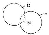
열 결합에서, 섬유의 결합 부분이 개략도 4a 및 4b에 예시된 바와 같은 원주-침투 유형의 결합을 형성하기 충분하게 유동할 때 최상의 결합이 얻어진다. 이러한 결합은 결합된 섬유들 사이에 보다 강한 접촉을 만들고, 증가된 접촉 면적은 결합 강도를 증가시킨다. 도 4a는 한 섬유 또는 세그먼트(52)가 변형되는 반면, 다른 섬유 또는 세그먼트(53)은 본질적으로 그의 횡단면 형태를 보유하는 결합을 예시한다. 도 4b는 2개의 섬유들(55 및 56)이 결합되고 각각이 횡단면 형태에 있어서 변형되는 결합을 예시한다. 도 4a 및 4b 모두에, 원주-침투 결합이 나타나 있으며; 도 4a에서의 점선(54)는 섬유(53)의 침투에 의해 야기된 변형을 제외하고 섬유(52)가 가지게 되는 형태를 나타내고; 및 도 4b에서의 점선(57 및 58)은 섬유(56 및 55) 각각이 결합을 제외하고 가지게 되는 형태를 나타낸다. 도 4는 원주-침투 결합과 상이할 수 있는 결합으로 함께 결합된 2개의 섬유를 개략적으로 예시하며, 여기서 1개 이상의 섬유들의 외부 부분으로부터의 물질이 융합되어 섬유들 중 어느 하나의 원주로 실제 침투하지 않고서 2개의 섬유들을 함께 연결시킨다.In thermal bonding, the best bonding is obtained when the bonding portion of the fiber flows sufficiently to form a column-penetrating type of bonding as illustrated in schematics 4a and 4b. This bond makes stronger contact between the bonded fibers, and the increased contact area increases the bond strength. 4A illustrates a bond in which one fiber or
도 4a-4c에 묘사된 결합은 예를 들면, 칼렌더링 압력의 인가없이 본 발명의 웹을 가열함으로써 얻어진 자생적 결합일 수 있다. 이러하 결합은 웹에 보다 부드러운 감촉 및 압력 하에서의 보다 큰 로프트 보유를 가능하게 한다. 그러나, 점-결합 또는 면적-너비 칼렌더링과 같은 가압 결합도 또한 유용하다. 결합은 또한 섬유들 사이의 결합을 열적으로 또는 다른 방식으로 활성화시키는 적외선, 레이저, 초음파 또는 다른 에너지 형태의 인가에 의해 형성될 수도 있다. 용매 인가도 또한 사용될 수 있다. 웹이 결합들 중 단지 일부에서만 쓸모있는 제한된 압력만을 받을 때에서와 같이, 웹은 자생적 결합 및 압력-형성된 결합 모두를 나타낼 수 있다. 자생적 결합을 갖는 웹은 다른 종류의 압력-형성된 결합들이 또한 제한된 양으로 존재한다 할지라도, 본원에서 자생적으로 결합된 것으로 간주된다. 일반적으로, 발명을 실행하는데 있어서, 결합 작업은 바람직하게는 일부 길이방향 세그먼트들이 연화될 수 있고, 인접하는 섬유 또는 한 섬유의 일부분에 결합하는데 있어서 활성이게 하면서도, 다른 길이방향 세그먼트들은 결합을 달성하는데 있어서 수동적 또는 비활성으로 남아있도록 선택된다.The bonds depicted in FIGS. 4A-4C can be, for example, autogenous bonds obtained by heating the web of the present invention without the application of calendering pressure. This bonding allows for a softer feel to the web and greater loft retention under pressure. However, pressure bonding, such as point-bonding or area-width calendaring, is also useful. The bond may also be formed by application of infrared, laser, ultrasonic or other energy forms that thermally or otherwise activate the bond between the fibers. Solvent application may also be used. As when the web is subject to limited pressure available only in some of the bonds, the web can exhibit both autogenous and pressure-formed bonds. Webs with autogenous bonds are considered herein autogenously bonded, although other types of pressure-formed bonds may also be present in limited amounts. In general, in carrying out the invention, the joining operation preferably allows some longitudinal segments to be softened and active in bonding to adjacent fibers or portions of one fiber, while the other longitudinal segments serve to achieve joining. Is selected to remain passive or inactive.
본 발명은 섬유-형성 중합체 물질이 한 본질적으로 직접적인 작업(필라멘트의 압출, 필라멘트의 가공 및 고화, 가공된 필라멘트들의 수집, 및 필요할 경우, 수집된 덩어리를 웹으로 변형시키는 추가의 가공)으로 웹으로 변환되는 직접-웹 형성 방법으로서 유용한다. 본 발명의 부직 섬유상 웹은 바람직하게는 직접적으로 수집된 섬유 또는 직접적으로 수집된 섬유의 덩어리를 포함하고, 섬유들이 섬유-형성 장치를 떠날 때 이들이 웹과 같은 덩어리로 수집되는 것을 의미한다. 다른 성분들, 예를 들면 스테이플 섬유 또는 입자들, 또는 다른 직접적으로 형성된 섬유들은 본 발명의 직접적으로 형성된 섬유들의 덩어리와 함께 수집될 수 있다.The present invention relates to a web in which a fiber-forming polymer material is inherently a direct operation (extrusion of filaments, processing and solidification of filaments, collection of processed filaments, and, if necessary, further processing to transform the collected mass into a web). It is useful as a direct-web formation method to be converted. The nonwoven fibrous web of the present invention preferably comprises directly collected fibers or agglomerates of directly collected fibers, which means that when the fibers leave the fiber-forming apparatus they are collected into agglomerates such as webs. Other components, such as staple fibers or particles, or other directly formed fibers may be collected with the mass of directly formed fibers of the present invention.
본 발명에 따라 제조된 섬유의 평균 직경은 광범위하게 변할 수 있다. 미세섬유 크기(직경이 약 10 마이크로미터 미만)가 얻어질 수 있고, 몇몇 이점들을 제공할 수 있지만; 보다 큰 직경을 갖는 섬유들도 또한 제조될 수 있고, 특정 용도에 유용하며; 종종 섬유들은 직경이 20 마이크로미터 이하이다. 원형 횡단면을 갖는 섬유들이 가장 자주 제조되지만, 다른 횡단면 형태들도 또한 사용될 수 있다. 선택된 작업 파라미터들에 따라, 수집된 섬유들은 오히려 연속적이거나 또는 불연속적일 수 있다.The average diameter of the fibers produced according to the invention can vary widely. Microfiber size (less than about 10 micrometers in diameter) can be obtained and may provide some advantages; Fibers with larger diameters can also be produced and are useful for certain applications; Often the fibers are 20 micrometers or less in diameter. Fibers with a circular cross section are most often produced, but other cross sectional shapes may also be used. Depending on the chosen working parameters, the collected fibers can be rather continuous or discontinuous.
상기 나타낸 바와 같이, 본 발명에 따르면, 필라멘트들은 빠른 속도로 가공된다. 예를 들면, 폴리프로필렌은 가공 챔버를 통과할 때 8000 미터/분의 겉보기 필라멘트 속도로 가공되는 것으로 알려지지 않지만, 이러한 겉보기 속도는 도 1-3에 나타낸 바와 같은 장치와 함께 가능하다(예를 들면 중합체 유량, 중합체 밀도, 및 평균 섬유 직경으로부터 속도가 계산되기 때문에, 용어 겉보기 필라멘트 속도가 사용된다). 2800 미터/분 이상의 필라멘트 속도가 본 발명에 이점을 제공하는 것으로 밝혀졌고; 일반적으로 본 발명자들은 4000 또는 5000 미터/분 이상의 필라멘트 속도에서 작업하는 것을 선호한다. 도 1-3에 나타낸 바와 같은 장치 상에서 더욱 더 빠른 겉보기 필라멘트 속도, 예를 들면 10,000 미터/분 또는 심지어 14,000 또는 18,000 미터/분이 달성되었고, 이들 속도는 광범위의 중합체로 얻어질 수 있다.As indicated above, according to the present invention, the filaments are processed at high speed. For example, polypropylene is not known to be processed at an apparent filament speed of 8000 meters / minute as it passes through the processing chamber, but this apparent speed is possible with a device as shown in FIGS. 1-3 (eg, a polymer). Since the velocity is calculated from the flow rate, polymer density, and average fiber diameter, the term apparent filament velocity is used). Filament speeds of at least 2800 meters / minute have been found to provide an advantage in the present invention; In general, we prefer to work at filament speeds of 4000 or 5000 meters / minute or more. Even faster apparent filament speeds, for example 10,000 meters / minute or even 14,000 or 18,000 meters / minute, have been achieved on the device as shown in FIGS. 1-3, and these rates can be obtained with a wide range of polymers.
추가적으로, 압출 헤드 내 오리피스 당 많은 부피의 중합체가 가공될 수 있고, 이들 큰 부피는 압출된 필라멘트들이 고속으로 이동함과 동시에 가공될 수 있다. 이러한 조합은 높은 생산성 지수(중합체 처리량 속도(예를 들면, 분 당 오리피스 당의 그램 단위)에 압출된 필라멘트의 겉보기 속도(예를 들면, 분 당 미터 단위)를 곱한 것)를 야기시킨다. 본 발명의 방법은 직경이 평균 20 마이크로미터 이하인 필라멘트들을 생성하는 동안에 조차도 9000 이상의 생산성 지수로 쉽게 실행될 수 있다.In addition, a large volume of polymer per orifice in the extrusion head can be processed, and these large volumes can be processed simultaneously with the extruded filaments moving at high speed. This combination results in a high productivity index (polymer throughput rate (eg in grams per orifice per minute) multiplied by the apparent rate of extruded filaments (eg in meters per minute)). The method of the present invention can be easily implemented with a productivity index of 9000 or more, even while producing filaments having an average diameter of 20 micrometers or less.
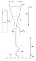
도 6 및 7은 본 발명에 관련된 용어 및 개념들 중 일부를 예시한다. 도 6은 본 발명에 따라 용융된 섬유-형성 물질로부터 제조되어 섬유로 가공된 대표적인 압출된 필라멘트(80)의 개략도이고; 이 도면은 가공되고 치수가 변할 때의 필라멘트를 나타내지만, 실제로 섬세화 또는 다른 장치를 통과하는 필라멘트들을 보여주지 않는다. 개략도에서의 치수는 크게 확대된 것으로, 참 치수를 정확하게 나타내려는 것이 아니다.6 and 7 illustrate some of the terms and concepts related to the present invention. 6 is a schematic diagram of an exemplary
도 6에 나타낸 바와 같이, 필라멘트들은 압출 헤드(81)로부터 압출되어 수집기(82)로 이동한다. 필라멘트는 가공 챔버를 통과하지만, 예시의 목적상, 가공 챔버(83)은 필라멘트에 비하여 지극히 작은 규모로 그려져 있고, 실선의 측면(실선 상에서의 보통 위치라기 보다는)에 위치되어 있다.As shown in FIG. 6, the filaments are extruded from the
용융 필라멘트(80)이 압출 헤드(81)을 떠날 때, 이것은 대표적으로는 압출 헤드의 구속으로부터 방출 때문에 크기가 팽윤된다. 이어서, 인가된 연신 힘, 예를 들면 가공 챔버를 관통하여 부는 공기의 잡아당김 때문에 직경이 좁아진다. 압출된 필라멘트는 이들이 압출 헤드로부터 추가로 멀어지게 및 수집기를 향해 이동할 때 계속해서 직경이 좁아지고, 이 동안 필라멘트들이 냉각된다(예를 들면, 냉각기 공기, 예를 들면 공기 또는 다른 기체의 주위의 또는 급냉 스트림이 대표적으로 섬유를 둘러싸기 때문에). 직경이 좁아지는 것은 필라멘트들이 필라멘트상 물질의 고화/용융 온도(결정질 또는 반결정질 물질의 경우) 또는 유리 전이 온도(무정형 물질의 경우)에 이를 때까지 본질적으로 계속되고; 필라멘트가 고화/용융 온도 또는 유리 전이 온도에 도달하는 위치를 실선 상에서 영역(85), 뿐만 아니라, 이 영역이 정확한 지점일 필요는 없지만 대표적으로는 실선을 따른 거리에 대하여 연장되게 됨을 나타내기 위해 막대에 의해 표시된 Tm/Tg로 표시된다. 영역(85)로부터 수집기를 향하여, 필라멘트들은 본질적으로 그의 직경을 보유할 수 있고; 어느 정도의 좁아짐은 필라멘트에 인가된 연신력이 충분히 클 경우, 어느 정도의 좁아짐이 계속될 수 있다.When the
본 발명에 따라, 영역 (85) 및 가공 챔버(83)의 상대적 위치가 변할 수 있다. 가공 챔버에 대한 한 예시적인 위치는 굵은 선으로 나타나 있지만, 가공 챔버는 또한 점선으로 제시된 범위 내에서 상이한 위치를 차지할 수도 있고; 점선은 가공 챔버의 가능한 위치를 전체적으로 설명하거나 또는 배타적으로 설명하고자 하는 것이 아니다. 달리 말하면, 압출된 필라멘트(80)은 이들이 가공 챔버에 도달하기 전에, 이들이 가공 챔버에 있는 동안 또는 이들이 가공 챔버를 떠난 후에, Tm 또는 Tg에 일치하는 온도에 도달할 수 있다.According to the present invention, the relative positions of the
압출된 필라멘트가 가공 챔버를 떠난 후에는 일반적으로 난류 영역을 통해 이동한다. 난류는 가공 챔버를 통과하는 흐름이 챔버 내에서 존재하였던 압력이 해제되는, 챔버의 끝의 한정되지 않는 공간에 이르렀을 때, 일어난다. 흐름 스트림은 이들이 챔버를 빠져나올 때 넓어지게 되고, 확대된 스트림 내에서 소용돌이가 발생된다. 이들 소용돌이(주 스트림으로부터 상이한 방향으로 흐르는 흐름의 소용돌이)는 필라멘트가, 챔버 내에 있을 때 및 챔버에 도달하기 전에 필라멘트가 받는 직선상 힘과 상이한 힘을 받도록 한다. 예를 들면, 필라멘트는 (87)에 예시된, 여기저기로의 플랩핑(flapping)을 행할 수 있고, 필라멘트의 길에 대해 횡방향인 벡터 성분을 갖는 힘을 받을 수 있다. 가공 챔버를 지나 난류장에 인가된 힘은 압출된 필라멘트가 압출 헤드로부터 수집기로 이동하는 동안에 이들에 의해 경험되는 가장 강한 것일 수 있다.After the extruded filaments leave the processing chamber, they generally travel through the turbulent region. Turbulence occurs when the flow through the processing chamber reaches an undefined space at the end of the chamber where the pressure that was present in the chamber is released. The flow streams widen as they exit the chamber and vortex in the enlarged stream. These vortices (vortices of flow flowing in different directions from the main stream) cause the filaments to be subjected to a force different from the linear force that the filament receives when in the chamber and before reaching the chamber. For example, the filament may flap to and fro, illustrated in 87, and may receive a force having a vector component transverse to the length of the filament. The force applied to the turbulent field past the processing chamber may be the strongest experienced by them while the extruded filaments move from the extrusion head to the collector.
도 6은 또한 Tm 또는 Tg가 나타낸 위치에 있다고 가정할 때 필라멘트가 배향 온도 또는 배향-고착 온도에 있을 수 있는 실선을 따른 위치들의 대표적인 범위를 개략적으로 보여준다. 도 6에 나타낸 바와 같이, 필라멘트는 일반적으로 Tm 또는 Tg가 나타낸 위치에 있을 때 선(88)에 의해 나타내어지는 위치들의 범위 내에서 배향 온도에 있을 수 있다. 필라멘트는 일반적으로 Tm 또는 Tg가 나타낸 위치에 있을 때 선(89)에 의해 나타내어지는 위치들의 범위 내에서 배향-고착 온도를 달성할 수 있다.6 also schematically shows a representative range of locations along the solid line where the filament may be at the orientation temperature or orientation-fixing temperature, assuming that Tm or Tg is at the indicated position. As shown in FIG. 6, the filament may generally be at an orientation temperature within the range of locations represented by
도 7은 필라멘트들이 Tm 또는 Tg에 도달되는 특정 영역을 확인하지 않고서 필라멘트(80)을 나타내는 다른 개략도이다. 이러한 개략도의 의도는 압출기로부터 다양한 거리에서 압출된 필라멘트들이 배향 온도 또는 배향-고착 온도에 있을 수 있음을 나타내기 위한 것이다. 도 7에 나타낸 바와 같이, 선(88')에 의해 나타내어지는, 필라멘트가 배향 온도로 남아 있는 위치들의 범위는 압출 헤드(81)(필라멘트-형성 물질이 대표적으로는 Tm 또는 Tg보다 30-40 ℃ 이상인 온도(TE)에 있는 경우)로부터 수집기 부근의 위치로 연장될 수 있다. 그리고 거꾸로 말하면, 선(89')에 의해 나타내어지는, 필라멘트가 배향-고착 온도에 도달하는 위치들의 범위는 수집기(82) 부근의 위치로부터 가공 챔버(83)의 앞(업스트림)의 위치로 연장될 수 있다.7 is another schematic diagram illustrating the
섬유-형성 방법에 대한 부속물로서 종래적으로 사용된 각종 방법들은 마무리처리제 또는 다른 물질들의 필라멘트 상으로의 분무, 정전하의 필라멘트 상으로의 인가, 워터 미스트의 인가 등과 같이, 필라멘트들이 섬세화기로 들어가거나 또는 나올 때 필라멘트와 함께 사용될 수 있다. 또한, 결합제, 접착제, 마무리처리제 및 다른 웹 또는 필름을 포함하는 각종 물질들이 수집된 웹에 첨가될 수 있다.Various methods conventionally used as an adjunct to the fiber-forming method include filaments entering the refiner, such as spraying of a finishing agent or other materials onto the filaments, application of electrostatic charges onto the filaments, application of water mist, or the like. Or can be used with the filament when it comes out. In addition, various materials can be added to the collected web, including binders, adhesives, finishes, and other webs or films.
비록 대표적으로 그렇게 할 이유가 있는 것은 아니지만, 필라멘트들은 종래의 멜트블로잉 작업에 사용된 것의 방식으로 주요 기체 스트림에 의해 압출 헤드로부터 블로잉될 수 있다. 이러한 주 기체 스트림은 필라멘트의 초기 섬세화 및 연신을 야기시킨다.Although typically there is no reason to do so, the filaments can be blown from the extrusion head by the main gas stream in the manner used in conventional meltblowing operations. This main gas stream causes initial refinement and stretching of the filaments.
실시예 1-4Example 1-4
도 1-3에 나타낸 바와 같은 장치를 사용하여 4개의 상이한 섬유상 웹을 제조하였다. 웹 중 2개, 실시예 1 및 실시예 2는 폴리우레탄 수지(유타주 솔트 레이크 시티의 헌츠만 폴리우레탄즈(Huntsman Polyurethanes)가 공급하는 PS440-200, 25 g/10분의 용융 유량을 가짐)로부터 제조되었다. 폴리우레탄을 압출기 중에서 221℃(펌프(13)으로의 출구 부근의 압출기(12) 내에서 측정된 온도)로 가열시키고, 다이를 하기 표 1에 열거한 바와 같은 온도로 가열하였다.Four different fibrous webs were prepared using the apparatus as shown in FIGS. 1-3. Two of the webs, Examples 1 and 2, were prepared from a polyurethane resin (PS440-200, supplied by Huntsman Polyurethanes, Salt Lake City, Utah, with a melt flow rate of 25 g / 10 minutes). Was prepared. The polyurethane was heated in the extruder to 221 ° C. (the temperature measured in the
나머지 2개의 웹, 실시예 3 및 4는 폴리에틸렌 수지(델라웨어주 윌밍톤의 듀퐁-다우 엘라스토머스(Dupont-Dow Elastomers)로부터 입수가능한 인게이지(Engage) 8411, 공단량체로서 33%의 옥텐을 포함하고(%는 달리 나타내지 않는 한 중량%임), 18 g/10분의 용융 유량을 가짐)로부터 제조되었다. 폴리에틸렌을 압출기 중에서 271℃(펌프(13)으로의 출구 부근의 압출기(12) 내에서 측정된 온도)로 가열시키고, 다이를 하기 표 1에 열거한 바와 같은 온도로 가열하였다.The other two webs, Examples 3 and 4, comprise Engage 8411, a comonomer of 33% octene, available from polyethylene resin (Dupont-Dow Elastomers, Wilmington, Delaware). (% Is by weight unless otherwise indicated), and has a melt flow rate of 18 g / 10 minutes. The polyethylene was heated to 271 ° C. (temperature measured in
4개의 실시예에서, 압출 헤드 또는 다이는 16열의 오리피스들을 가졌고; 실시예 1 및 2에서는, 각 열이 32개의 오리피스를 가져, 총 512개의 오리피스들을 만들었고; 실시예 3 및 4에서는, 각 열이 16개의 오리피스를 가져, 총 256개의 오리피스들을 만들었다. 다이는 7.875 인치(200 밀리미터)의 횡방향 길이를 가졌다. 홀 직경은 0.040 인치(0.889 ㎜)이었고 L/D 비는 6이었다. 중합체 유량은 실시예 3 및 4에서 0.89 g/홀/분 및 0.98 g/홀/분이었다.In four embodiments, the extrusion head or die had 16 rows of orifices; In Examples 1 and 2, each row had 32 orifices, making a total of 512 orifices; In Examples 3 and 4, each row had 16 orifices, making a total of 256 orifices. The die had a transverse length of 7.875 inches (200 millimeters). The hole diameter was 0.040 inch (0.889 mm) and the L / D ratio was 6. Polymer flow rates were 0.89 g / hole / minute and 0.98 g / hole / minute in Examples 3 and 4.
다이와 섬세화기 사이의 거리(도 1에서의 치수(17))는 37 인치(약 94 센티미터)이었고, 섬세화기로부터 수집기까지의 거리(도 1에서의 치수(21))는 26.75 인치(68 센티미터)였다. 에어 나이프 갭(도 2에서의 치수(30))은 0.030 인치(0.76 밀리미터)이었고; 섬세화기 본체 각(도 2에서의 α)은 30도이었고; 실온 공기가 섬세화기를 통과하였으며; 섬세화기 슈트의 길이(도 2의 치수(35))는 6 인치(152 밀리미터)이었다. 에어 나이프는 약 251 밀리미터의 횡방향 길이(도 3에서의 슬롯의 길이(25)의 방향)를 가졌고; 에어 나이프에 대한 홈이 형성되어 있는 섬세화기 본체(28)은 약 330 밀리미터의 횡방향 길이를 가졌다. 섬세화기 본체에 부착된 벽(36)의 횡방향 길이는 14 인치(406 밀리미터)이었다.The distance between the die and the refiner (
섬세화기의 상부 및 바닥에서의 갭(각각 도 2에서의 치수(33 및 34)); 섬세화기를 통과한 공기의 총 부피(실제 입방 미터/분 또는 ACMM으로 주어짐; 열거된 부피의 대략 반이 각 에어 나이프(32)를 통과하였음); 및 필라멘트 속도(겉보기)를 포함하는 다른 섬세화기 파라미터들은 표 1(아래 실시예 끝에 있음)에 설명되어 있는 바와 같다. 섬세화기의 벽 상에서의 클램핑 압력은 실시예 1 및 2에서는 약 500 킬로파스칼이었고, 실시예 3 및 4에서는 약 550 킬로파스칼이었으며, 2개의 압력 모두 공정 동안의 이동에 대하여 벽을 고정시키는 경향이 있었다.Gaps at the top and bottom of the refiner (
실시예 1 및 2의 웹은 이들을 1.5 인치(3.8 센티미터)의 슬롯 폭(기계-방향 치수) 및 초 당 21 미터의 면 속도로 0.11 초의 노출 시간 동안 95 ℃로 설정된 고온 에어 나이프 아래를 통과시킴으로써 어닐링시켰다.The webs of Examples 1 and 2 were annealed by passing them under a hot air knife set at 95 ° C. for an exposure time of 0.11 seconds at a slot width (machine-direction dimension) of 1.5 inches (3.8 centimeters) and a surface speed of 21 meters per second. I was.
실시예 3 및 4의 웹은 이들을 1.5 인치(3.8 센티미터)의 슬롯 폭 및 초 당 19 미터의 면 속도로 0.19 초의 노출 시간 동안 90 ℃로 설정된 고온 에어 나이프 아래를 통과시킴으로써 어닐링시켰다.The webs of Examples 3 and 4 were annealed by passing them under a hot air knife set at 90 ° C. for an exposure time of 0.19 seconds at a slot width of 1.5 inches (3.8 centimeters) and a plane speed of 19 meters per second.
편광 현미경을 사용한 복굴절 연구를 비롯한 광학적 관찰을 제조한 웹(어닐링 후) 상에서 수행하여 웹의 섬유들 내에서의 배향도를 관찰하여 그 결과를 표 2(실시예의 끝부분에 있음)에 보고한다. 섬유들의 복굴절을 뉴욕주 멜빌 월트 와이트맨 로드 1300의 니콘 인스트루먼츠 인크.(Nikon Instruments Inc.)에 의해 제조된 니콘 이클립스(Nikon Eclipse) E600 편광 현미경을 사용하여 측정하였다. 측정치를 구하는데 문헌[Berek Compensator Instructions, Nichika Corporation, Japan, Revision 8/10/2001]에 의해 개괄화된 베렉 보상기 기술을 사용하였다. 측정을 위한 프로토콜은 다음과 같다: 현미경을 물체, 광학체, 콘덴서 및 광원의 중심에 조심스럽게 정렬시킨다. 측정해야 할 섬유를 시야의 중심에 위치시킨다. 스테이지를 시야 내 남-북 정렬에 가장 가까운 흡광 위치로 회전시킨다. 샘플을 시계반대방향으로 45도 회전시킨다. 브렉 보상기를 사용하여 섬유의 중심에 검정색 밴드가 나타날 때까지 드럼을 시계방향으로 돌린다. 도 단위의 판독치를 표시한다. 브렉 보상기를 사용하여 섬유의 중심에 검정색 밴드가 나타날 때까지 드럼을 시계반대방향으로 돌린다. 도 단위의 판독치를 표시한다. 기울기는 판독치들 사이의 차를 2로 나눈 것이다.Optical observations, including birefringence studies using a polarization microscope, were made on the prepared web (after annealing) to observe the degree of orientation in the fibers of the web and the results are reported in Table 2 (at the end of the examples). The birefringence of the fibers was measured using a Nikon Eclipse E600 polarized microscope manufactured by Nikon Instruments Inc. of Melville Walt Whiteman Road 1300, NY. The Berek compensator technique outlined by Berek Compensator Instructions, Nichika Corporation, Japan, Revision 8/10/2001 was used to obtain the measurements. The protocol for the measurement is as follows: Carefully align the microscope to the center of the object, optics, condenser and light source. Position the fiber to be measured at the center of the field of view. Rotate the stage to the absorbance position closest to the north-south alignment in the field of view. Rotate the sample 45 degrees counterclockwise. Using a Breck compensator, turn the drum clockwise until a black band appears in the center of the fiber. Displays readings in degrees. Using a Breck compensator, turn the drum counterclockwise until a black band appears in the center of the fiber. Displays readings in degrees. The slope is the difference between the readings divided by two.
지연 값은 제조업자가 제공한 표로부터 또는 기계 상수를 알아 계산에 의해 얻을 수 있으며; 실시예 1-4의 경우, 계산 방정식은 R = 10000 F(i) x C/10000(여기서, F(i)은 제조업자가 제공한 표로부터 얻고, C/10000은 1.009 임)이다. 이어서 복굴절이 측정된 지점에서 섬유의 직경을 측정하고, 지연 값을 직경으로 나누어서 복굴절을 계산한다. 값들을 대표적인 1개의 섬유의 10개의 판독치들의 최소 평균으로서 보고한다.The delay value can be obtained from a table provided by the manufacturer or by calculation by knowing the machine constants; For Examples 1-4, the calculation equation is R = 10000 F(i) x C / 10000, where F(i) is obtained from a table provided by the manufacturer and C / 10000 is 1.009. The diameter of the fiber is then measured at the point where birefringence is measured, and birefringence is calculated by dividing the delay value by the diameter. The values are reported as the minimum average of ten readings of one representative fiber.
후속 결합 단계에서, 실시예 3 및 4의 웹들을 2-롤 칼렌더를 사용하여 용봉시켰다. 칼렌더 셋팅은 다음과 같았다:In a subsequent joining step, the webs of Examples 3 and 4 were sealed using a two-roll calendar. The calendar settings were as follows:
상부 롤 -Upper roll-
○ 20% 결합 면적을 갖는 점 결합 다이아몬드 패턴○ Point bonded diamond pattern with 20% bond area
○ 점들은 1 ㎜ x 1 ㎜ 랜드 면적을 갖는다.The points have a 1 mm x 1 mm land area.
○ 10 인치(25.4 ㎝)의 외부 직경과 22 인치(56 ㎝) 폭(드럼의 축을 따라)10 inches (25.4 cm) outside diameter and 22 inches (56 cm) wide (along the axis of the drum)
○ 롤 중의 오일 온도 = 155 ℉(68 ℃)O Oil temperature in rolls = 155 ° F (68 ° C)
○ 웹 속도 5 피트/분(1.52 미터/분)○ Web speed 5 feet / minute (1.52 meters / minutes)
바닥 롤-Floor roll
○ 평활한 강○ smooth river
○ 10 인치(25.4 ㎝)의 외부 직경과 22 인치(56 ㎝) 폭(드럼의 축을 따라)10 inches (25.4 cm) outside diameter and 22 inches (56 cm) wide (along the axis of the drum)
○ 롤 중의 오일 온도 = 155 ℉(68 ℃)O Oil temperature in rolls = 155 ° F (68 ° C)
○ 웹 속도 5 피트/분(1.52 미터/분)○ Web speed 5 feet / minute (1.52 meters / minutes)
닙 압력 - 100 psi(689 kPa)Nip Pressure-100 psi (689 kPa)
인장 시험들을 인스트론(Instron) 모델 5544 인장 시험 기계로 웹의 샘플들 상에서 수행하였다. 3개의 기계-방향 샘플(섬유를 제조한 것과 동일한 방향으로 웹으로부터 절단된 샘플) 및 3개의 횡-방향 샘플을 10 인치(25.4 ㎝)/분 크로스헤드 속도, 2 인치(5.08 ㎝) 조(jaw) 갭, 및 1 x 4 인치(2.54 x 5.08 센티미터)로 절단된 샘플 스트립을 사용하여 시험하였다. 유사한 샘플들을 그들의 원래의 길이의 200%로 신축시키고 해제시킬 때, 이들은 그들의 원래의 길이의 125% 미만으로 신속하게(수 초 이내에) 회복된다.Tensile tests were performed on samples of the web with an Instron model 5544 tensile test machine. Three machine-direction samples (samples cut from the web in the same direction as the fibers were made) and three transverse-direction samples were taken at 10 inch (25.4 cm) / min crosshead speed, 2 inch (5.08 cm) jaw ) Gap, and sample strips cut to 1 x 4 inches (2.54 x 5.08 centimeters). When similar samples are stretched and released at 200% of their original length, they recover quickly (within seconds) to less than 125% of their original length.
실시예 5 및 6Examples 5 and 6
도 1-3에 나타낸 바와 같은 장치를 사용하여 디블록 중합체 및 다른 성분들의 블렌드로부터 2개의 상이한 섬유상 웹을 제조하였다. 실시예 5는 60%의 스티렌계 블록 공중합체(텍사스주 휴스톤의 크라톤® 폴리머스로부터 입수가능한 크라톤(Kraton)(등록상표) D1119P, 약 34%의 SIS 공중합체 및 약 66%의 SI 디블록으로 이루어지고 약 22%의 스티렌 함량을 가짐) 및 40% 광유(텍사스주 미들랜드의 쉐브론 텍사코 코포레이션(Chevron Texaco Corporation)으로부터 입수가능한 쉐브론 수펄라(Chevron Superla)(등록상표) 와이트 오일(White Oil) 31)의 블렌드를 사용하였다. 블렌드를 압출기 중에서 253℃(펌프(13)으로의 출구 부근의 압출기(12) 내에서 측정된 온도)로 가열시키고, 다이를 하기 표 1에 열거한 바와 같은 온도로 가열 하였다.Two different fibrous webs were prepared from a blend of diblock polymers and other components using the apparatus as shown in FIGS. 1-3. Example 5 is 60% styrenic block copolymer (Kraton® D1119P, available from Kraton® Polymers, Houston, Texas, about 34% SIS copolymer and about 66% SI di) Consisting of blocks and having about 22% styrene content and 40% mineral oil (Chevron Superla® White Oil, available from Chevron Texaco Corporation, Midland, Texas) 31) was used. The blend was heated to 253 ° C. (temperature measured in
실시예 6은 90%의 상이한 스티렌계 블록 공중합체(텍사스주 휴스톤의 크라톤® 폴리머스로부터 입수가능한 크라톤(등록상표) RP 6936) 및 10%의 파라핀유(뉴저지주 필립스버그의 제이.티. 베이커(J.T. Baker)로부터 입수가능한 "파라핀 프릴스 퓨리파이드(Paraffin Prills Purified)")로 이루어진 블렌드를 사용하였다. 블렌드를 압출기 중에서 241℃(펌프(13)으로의 출구 부근의 압출기(12) 내에서 측정된 온도)로 가열시키고, 다이를 하기 표 1에 열거한 바와 같은 온도로 가열하였다.Example 6 shows 90% of different styrenic block copolymers (Kraton® RP 6936 available from Kraton® Polymers, Houston, Texas) and 10% paraffin oil (J.T., Phillipsburg, NJ). A blend consisting of "Paraffin Prills Purified" available from JT Baker was used. The blend was heated to 241 ° C. (temperature measured in
압출 헤드 또는 다이는 2열의 오리피스들을 가졌고; 각 열이 16개의 오리피스를 가져, 총 32개의 오리피스들을 만들었다. 다이는 4.125 인치(104.8 밀리미터)의 횡방향 길이를 가졌다. 홀 직경은 0.040 인치(0.889 ㎜)이었고 L/D 비는 6이었다. 중합체 유량은 2개의 실시예 모두에서 0.87 g/홀/분이었다.The extrusion head or die had two rows of orifices; Each row had 16 orifices, making a total of 32 orifices. The die had a transverse length of 4.125 inches (104.8 millimeters). The hole diameter was 0.040 inch (0.889 mm) and the L / D ratio was 6. The polymer flow rate was 0.87 g / hole / minute in both examples.
다이와 섬세화기 사이의 거리(도 1에서의 치수(17))는 2.7 인치(약 6.8 센티미터)이었고, 섬세화기로부터 수집기까지의 거리(도 1에서의 치수(21))는 22 인치(59 센티미터)였다. 에어 나이프 갭(도 2에서의 치수(30))은 0.050 인치(0.13 밀리미터)이었고; 섬세화기 본체 각(도 2에서의 α)은 30도이었고; 실온 공기가 섬세화기를 통과하였으며; 섬세화기 슈트의 길이(도 2의 치수(35))는 3 인치(76 밀리미터)이었다. 에어 나이프는 약 121 밀리미터의 횡방향 길이(도 3에서의 슬롯의 길이(25)의 방향)를 가졌고; 에어 나이프에 대한 홈이 형성되어 있는 섬세화기 본체(28)은 약 156 밀리미터의 횡방향 길이를 가졌다. 섬세화기 본체에 부착된 벽(36)의 횡방향 길이는 10 인치(254 밀리미터)이었다.The distance between the die and the refiner (
섬세화기의 상부 및 바닥에서의 갭(각각 도 2에서의 치수(33 및 34)); 섬세화기를 통과한 공기의 총 부피(실제 입방 미터/분 또는 ACMM으로 주어짐; 열거된 부피의 대략 반이 각 에어 나이프(32)를 통과하였음)를 포함하는 다른 섬세화기 파라미터들을 표 1에 기재되어 있는 바와 같이 변화시켰다. 섬세화기의 벽에 클램핑 압력을 인가하지 않아, 벽들이 공기압의 힘 하에 자유로이 이동하였다.Gaps at the top and bottom of the refiner (
실시예 5 및 6의 경우, 샘플들을 70℃에서 5분 동안 항온 오븐 중에 유지시키고 측정을 하기 전에 실온으로 하였다.For Examples 5 and 6 the samples were kept in a constant temperature oven at 70 ° C. for 5 minutes and brought to room temperature before the measurements were taken.
편광 현미경을 사용한 복굴절 연구를 비롯한 광학적 관찰을 제조한 웹(어닐링 후) 상에서 수행하여 웹의 섬유들 내에서의 배향도를 관찰하여 그 결과를 표 2(실시예의 끝부분에 있음)에 보고한다.Optical observations, including birefringence studies using a polarization microscope, were made on the prepared web (after annealing) to observe the degree of orientation in the fibers of the web and the results are reported in Table 2 (at the end of the examples).
실시예 7Example 7
도 1-3에 나타낸 바와 같은 장치를 사용하여 엘라스토머성 폴리에틸렌-기재 수지(델라웨어주 윌밍톤의 듀퐁-다우 엘라스토머스로부터 입수가능한 인게이지 8402(22% 옥텐 공단량체 함량))로부터 웹을 제조하였다. 수지를 압출기 중에서 240℃(펌프(13)으로의 출구 부근의 압출기(12) 내에서 측정된 온도)로 가열시키고, 다이를 하기 표 1에 열거한 바와 같은 온도로 가열하였다. 압출 헤드 또는 다이는 16열의 오리피스들을 가졌고, 각 열이 32개의 오리피스를 가져, 총 512개의 오리피스들을 만들었다. 다이는 8.0 인치(20.3 밀리미터)의 횡방향 길이를 가졌다. 홀 직경은 0.040 인치(0.889 ㎜)이었고 L/D 비는 6이었다. 중합체 유량은 0.5 g/홀/분이었다.The web was prepared from an elastomeric polyethylene-based resin (Engage 8402 (22% octene comonomer content) available from Dupont-Dow Elastomers, Wilmington, Delaware) using the apparatus as shown in FIGS. . The resin was heated to 240 ° C. (temperature measured in
다이와 섬세화기 사이의 거리(도 1에서의 치수(17))는 44 인치(약 112 센티미터)이었고, 섬세화기로부터 수집기까지의 거리(도 1에서의 치수(21))는 37.5 인치(92 센티미터)였다. 에어 나이프 갭(도 2에서의 치수(30))은 0.050 인치(0.127 밀리미터)이었고; 섬세화기 본체 각(도 2에서의 α)은 30도이었고; 실온 공기가 섬세화기를 통과하였으며; 섬세화기 슈트의 길이(도 2의 치수(35))는 6 인치(152 밀리미터)이었다. 에어 나이프는 약 251 밀리미터의 횡방향 길이(도 3에서의 슬롯의 길이(25)의 방향)를 가졌고; 에어 나이프에 대한 홈이 형성되어 있는 섬세화기 본체(28)은 약 330 밀리미터의 횡방향 길이를 가졌다. 섬세화기 본체에 부착된 벽(36)의 횡방향 길이는 14 인치(406 밀리미터)이었다. 가공 챔버의 벽 상에서의 클램핑 압력은 900 킬로파스칼이었고, 공정 동안의 이동에 대하여 벽을 고정시킨다.The distance between the die and the refiner (
섬세화기의 상부 및 바닥에서의 갭(각각 도 2에서의 치수(33 및 34)); 섬세화기를 통과한 공기의 총 부피(실제 입방 미터/분 또는 ACMM으로 주어짐; 열거된 부피의 대략 반이 각 에어 나이프(32)를 통과하였음)를 포함하는 다른 섬세화기 파라미터들을 또한 표 1에 기재되어 있는 바와 같이 변화시켰다.Gaps at the top and bottom of the refiner (
실시예 7의 수집된 배트(batt)를 6 매니폴드/젯(웹 위에 3 개 및 아래에 3개)로 이루어진 종래의 수압식 엔탱글링 시스템으로 히드로엔탱글링시켰다. 기본 작업 절차는 예를 들면 1995년 2월 14일에 에버하트 등에 특허허여된 미국 특허 제5,389,202호에(예를 들면 컬럼 8 및 9 참조) 기재되어 있다. 각 매니폴드는 120 미크론 직경의 오리피스 크기를 가졌다. 오리피스들을 매니폴드의 선 센티미터 당 약 16개의 오리피스들이 있는 간격으로 1열로 위치시켰다. 마니폴드 수압을 연속 적으로 10,000 kPa까지 올려 높은 에너지의 미세한 원주형 젯을 생성시켰다. 수압식 엔탱글링 표면은 테네시주 포틀랜드의 알바니 인터내셔날(Albany International)에 의해 제조된 단층 100 스텐레스 강 트윌직 와이어 배킹이었다. 수압식 엔탱글링 표면은 테네시주 포틀랜드의 알바니 인터내셔날에 의해 제조된 28%의 공면적을 갖는 단층 표준직 14 x 13 폴리에스테르 망이었다. 실시예 7의 물질을 분 당 약 5 미터의 선 속도로 매니폴드 아래를 통과시켜 이들을 종래의 실험실 핸드시트 건조기를 사용하여 80℃에서 건조시켜 샘플을 건조 및 어닐링시켰다. 어닐링 단계 동안에 일어난 섬유의 수축을 통해, 웹은 일체식 벽-형성된 시트 물질로서 보유되었고, 어닐링이 완료된 후에 탄성이며 부드럽고 치수적으로 안정한 물질이었다.The collected batts of Example 7 were hydroentangled with a conventional hydraulic entangled system consisting of six manifolds / jets (three above the web and three below). Basic operating procedures are described, for example, in US Pat. No. 5,389,202 (see, eg, columns 8 and 9), issued February 14, 1995 to Everhart et al. Each manifold had an orifice size of 120 microns in diameter. The orifices were placed in one row at intervals of about 16 orifices per line centimeter of the manifold. The manifold water pressure was continuously raised to 10,000 kPa, producing a high energy, fine columnar jet. The hydraulic entangling surface was a single layer 100 stainless steel twillic wire backing manufactured by Albany International, Portland, Tennessee. The hydraulic entangled surface was a monolayer standard 14 × 13 polyester mesh with a 28% co-area manufactured by Albany International, Portland, Tennessee. The materials of Example 7 were passed under the manifold at a linear speed of about 5 meters per minute and they were dried at 80 ° C. using a conventional laboratory handsheet dryer to dry and anneal the samples. Through the shrinkage of the fibers that occurred during the annealing step, the web was retained as an integral wall-formed sheet material and was an elastic, soft and dimensionally stable material after the annealing was completed.
편광 현미경을 사용한 복굴절 연구를 비롯한 광학적 관찰을 제조한 웹(어닐링 후) 상에서 수행하여 웹의 섬유들 내에서의 배향도를 관찰하여 그 결과를 표 2(실시예의 끝부분에 있음)에 보고한다.Optical observations, including birefringence studies using a polarization microscope, were made on the prepared web (after annealing) to observe the degree of orientation in the fibers of the web and the results are reported in Table 2 (at the end of the examples).
Claims (28)
Translated fromKoreanApplications Claiming Priority (3)
| Application Number | Priority Date | Filing Date | Title |
|---|---|---|---|
| US10/715,315 | 2003-11-17 | ||
| US10/715,315US20050106982A1 (en) | 2003-11-17 | 2003-11-17 | Nonwoven elastic fibrous webs and methods for making them |
| PCT/US2004/034666WO2005052238A1 (en) | 2003-11-17 | 2004-10-20 | Nonwoven elastic fibrous webs and methods for making them |
Publications (3)
| Publication Number | Publication Date |
|---|---|
| KR20070000413A KR20070000413A (en) | 2007-01-02 |
| KR20060136383Atrue KR20060136383A (en) | 2007-01-02 |
| KR101184871B1 KR101184871B1 (en) | 2012-09-20 |
Family
ID=34574197
Family Applications (1)
| Application Number | Title | Priority Date | Filing Date |
|---|---|---|---|
| KR1020067011900AExpired - Fee RelatedKR101184871B1 (en) | 2003-11-17 | 2004-10-20 | Nonwoven elastic fibrous webs and methods for making them |
Country Status (9)
| Country | Link |
|---|---|
| US (3) | US20050106982A1 (en) |
| EP (1) | EP1694899B1 (en) |
| JP (1) | JP4851336B2 (en) |
| KR (1) | KR101184871B1 (en) |
| CN (1) | CN1882734B (en) |
| AT (1) | ATE509149T1 (en) |
| BR (1) | BRPI0416610A (en) |
| TW (1) | TWI347385B (en) |
| WO (1) | WO2005052238A1 (en) |
Families Citing this family (39)
| Publication number | Priority date | Publication date | Assignee | Title |
|---|---|---|---|---|
| US7892993B2 (en) | 2003-06-19 | 2011-02-22 | Eastman Chemical Company | Water-dispersible and multicomponent fibers from sulfopolyesters |
| US20040260034A1 (en) | 2003-06-19 | 2004-12-23 | Haile William Alston | Water-dispersible fibers and fibrous articles |
| US8513147B2 (en) | 2003-06-19 | 2013-08-20 | Eastman Chemical Company | Nonwovens produced from multicomponent fibers |
| EP1730201B1 (en)* | 2004-03-03 | 2015-12-23 | Kraton Polymers U.S. LLC | Block copolymers having high flow and high elasticity |
| US7772322B2 (en)* | 2005-02-17 | 2010-08-10 | Sabic Innovative Plastics Ip B.V. | Poly(arylene ether) composition and articles |
| US8677513B2 (en) | 2005-04-01 | 2014-03-25 | Kimberly-Clark Worldwide, Inc. | Surgical sleeve for glove retention |
| US7685649B2 (en)* | 2005-06-20 | 2010-03-30 | Kimberly-Clark Worldwide, Inc. | Surgical gown with elastomeric fibrous sleeves |
| US20070055015A1 (en)* | 2005-09-02 | 2007-03-08 | Kraton Polymers U.S. Llc | Elastomeric fibers comprising controlled distribution block copolymers |
| US8246898B2 (en) | 2007-03-19 | 2012-08-21 | Conrad John H | Method and apparatus for enhanced fiber bundle dispersion with a divergent fiber draw unit |
| JP2010535295A (en)* | 2007-07-30 | 2010-11-18 | スリーエム イノベイティブ プロパティズ カンパニー | Porous finishing materials, acoustic damping composites, and methods for making and using them |
| US8337664B2 (en)* | 2007-12-31 | 2012-12-25 | Philip Morris Usa Inc. | Method and apparatus for making slit-banded wrapper using moving orifices |
| US9168718B2 (en) | 2009-04-21 | 2015-10-27 | Exxonmobil Chemical Patents Inc. | Method for producing temperature resistant nonwovens |
| US8748693B2 (en) | 2009-02-27 | 2014-06-10 | Exxonmobil Chemical Patents Inc. | Multi-layer nonwoven in situ laminates and method of producing the same |
| US9498932B2 (en) | 2008-09-30 | 2016-11-22 | Exxonmobil Chemical Patents Inc. | Multi-layered meltblown composite and methods for making same |
| US8664129B2 (en) | 2008-11-14 | 2014-03-04 | Exxonmobil Chemical Patents Inc. | Extensible nonwoven facing layer for elastic multilayer fabrics |
| US10161063B2 (en) | 2008-09-30 | 2018-12-25 | Exxonmobil Chemical Patents Inc. | Polyolefin-based elastic meltblown fabrics |
| FI124075B (en)* | 2009-03-26 | 2014-03-14 | Metso Paper Inc | A method and apparatus for controlling shrinkage of a fibrous web and a method for renewing a cutting area of a papermaking machine |
| US8512519B2 (en) | 2009-04-24 | 2013-08-20 | Eastman Chemical Company | Sulfopolyesters for paper strength and process |
| US8162153B2 (en)* | 2009-07-02 | 2012-04-24 | 3M Innovative Properties Company | High loft spunbonded web |
| US8668975B2 (en) | 2009-11-24 | 2014-03-11 | Exxonmobil Chemical Patents Inc. | Fabric with discrete elastic and plastic regions and method for making same |
| CN101892527B (en)* | 2010-06-30 | 2015-05-13 | 江苏丽洋新材料股份有限公司 | Fiber aggregate material formed by coating fine air pockets by microfibers and production process thereof |
| US9273417B2 (en) | 2010-10-21 | 2016-03-01 | Eastman Chemical Company | Wet-Laid process to produce a bound nonwoven article |
| WO2012174204A2 (en) | 2011-06-17 | 2012-12-20 | Fiberweb, Inc. | Vapor permeable, substantially water impermeable multilayer article |
| US10369769B2 (en) | 2011-06-23 | 2019-08-06 | Fiberweb, Inc. | Vapor-permeable, substantially water-impermeable multilayer article |
| US9827755B2 (en) | 2011-06-23 | 2017-11-28 | Fiberweb, Llc | Vapor-permeable, substantially water-impermeable multilayer article |
| EP2723567A4 (en) | 2011-06-24 | 2014-12-24 | Fiberweb Inc | Vapor-permeable, substantially water-impermeable multilayer article |
| US8840757B2 (en) | 2012-01-31 | 2014-09-23 | Eastman Chemical Company | Processes to produce short cut microfibers |
| CN104334783B (en)* | 2012-06-01 | 2016-10-05 | 日本喷丝板公司 | Non-woven cloth manufacturing device and non-woven fabrics manufacture method |
| US9303357B2 (en) | 2013-04-19 | 2016-04-05 | Eastman Chemical Company | Paper and nonwoven articles comprising synthetic microfiber binders |
| US9598802B2 (en) | 2013-12-17 | 2017-03-21 | Eastman Chemical Company | Ultrafiltration process for producing a sulfopolyester concentrate |
| US9605126B2 (en) | 2013-12-17 | 2017-03-28 | Eastman Chemical Company | Ultrafiltration process for the recovery of concentrated sulfopolyester dispersion |
| JP6158117B2 (en)* | 2014-02-28 | 2017-07-05 | アンビック株式会社 | Nonwoven insulation |
| CN105040147A (en)* | 2015-07-06 | 2015-11-11 | 陈援朝 | Preparation method and preparation system of elastic fiber which can be used for replacing low temperature spandex |
| CN110300820A (en) | 2017-02-10 | 2019-10-01 | 巴斯夫欧洲公司 | Method for producing elastic fiber, method for producing elastic fiber product, elastic fiber and elastic fiber product |
| TWI659137B (en)* | 2017-11-06 | 2019-05-11 | 三芳化學工業股份有限公司 | Composite fabric |
| WO2020097183A1 (en) | 2018-11-06 | 2020-05-14 | Kimberly-Clark Worldwide, Inc. | Method of making fine spunbond fiber nonwoven fabrics at high through-puts |
| EP4091212A1 (en) | 2020-01-15 | 2022-11-23 | 3M Innovative Properties Company | Thermal runaway barrier for a rechargeable electrical energy storage system |
| CN115176050A (en)* | 2020-03-05 | 2022-10-11 | 金伯利-克拉克环球有限公司 | Improved spunbonding system and process |
| EP4212654A4 (en)* | 2020-09-11 | 2024-04-10 | Asahi Kasei Kabushiki Kaisha | Polyurethane elastic fiber, gather member containing same, and sanitary material |
Family Cites Families (78)
| Publication number | Priority date | Publication date | Assignee | Title |
|---|---|---|---|---|
| US1975504A (en)* | 1929-12-07 | 1934-10-02 | Richard Schreiber Gastell | Process and apparatus for preparing artificial threads |
| US3630657A (en)* | 1969-04-01 | 1971-12-28 | Monsanto Co | Polyisocyanate treatment of polyurethane fibers |
| US3686385A (en)* | 1971-02-05 | 1972-08-22 | Mobil Oil Corp | Formation of elastic and high-tenacity fibers from butene-1 homopolymers and copolymers |
| JPS503831B2 (en)* | 1971-10-07 | 1975-02-10 | ||
| BE794339A (en)* | 1972-01-21 | 1973-07-19 | Kimberly Clark Co | NON-WOVEN MATERIALS |
| US4189338A (en)* | 1972-11-25 | 1980-02-19 | Chisso Corporation | Method of forming autogenously bonded non-woven fabric comprising bi-component fibers |
| FR2223318B1 (en)* | 1973-03-30 | 1978-03-03 | Saint Gobain | |
| US3971373A (en)* | 1974-01-21 | 1976-07-27 | Minnesota Mining And Manufacturing Company | Particle-loaded microfiber sheet product and respirators made therefrom |
| US3959421A (en)* | 1974-04-17 | 1976-05-25 | Kimberly-Clark Corporation | Method for rapid quenching of melt blown fibers |
| US4147749A (en)* | 1975-08-14 | 1979-04-03 | Allied Chemical Corporation | Varied orientation of fibers |
| CA1073648A (en)* | 1976-08-02 | 1980-03-18 | Edward R. Hauser | Web of blended microfibers and crimped bulking fibers |
| US4086381A (en)* | 1977-03-30 | 1978-04-25 | E. I. Du Pont De Nemours And Company | Nonwoven polypropylene fabric and process |
| US4163819A (en)* | 1977-12-27 | 1979-08-07 | Monsanto Company | Drapeable nonwoven fabrics |
| US4164600A (en)* | 1977-12-27 | 1979-08-14 | Monsanto Company | Thermal bonding of polyester polyblends |
| US4536361A (en)* | 1978-08-28 | 1985-08-20 | Torobin Leonard B | Method for producing plastic microfilaments |
| US4363646A (en)* | 1979-07-20 | 1982-12-14 | Torobin Leonard B | Method and apparatus for producing microfilaments |
| US4405297A (en)* | 1980-05-05 | 1983-09-20 | Kimberly-Clark Corporation | Apparatus for forming nonwoven webs |
| US4729371A (en)* | 1983-10-11 | 1988-03-08 | Minnesota Mining And Manufacturing Company | Respirator comprised of blown bicomponent fibers |
| US4692371A (en)* | 1985-07-30 | 1987-09-08 | Kimberly-Clark Corporation | High temperature method of making elastomeric materials and materials obtained thereby |
| US4707398A (en)* | 1986-10-15 | 1987-11-17 | Kimberly-Clark Corporation | Elastic polyetherester nonwoven web |
| US4820572A (en)* | 1986-10-15 | 1989-04-11 | Kimberly-Clark Corporation | Composite elastomeric polyether block amide nonwoven web |
| US4891957A (en)* | 1987-06-22 | 1990-01-09 | Kimberly-Clark Corporation | Stitchbonded material including elastomeric nonwoven fibrous web |
| US4813948A (en)* | 1987-09-01 | 1989-03-21 | Minnesota Mining And Manufacturing Company | Microwebs and nonwoven materials containing microwebs |
| US4988560A (en)* | 1987-12-21 | 1991-01-29 | Minnesota Mining And Manufacturing Company | Oriented melt-blown fibers, processes for making such fibers, and webs made from such fibers |
| US4939016A (en)* | 1988-03-18 | 1990-07-03 | Kimberly-Clark Corporation | Hydraulically entangled nonwoven elastomeric web and method of forming the same |
| US4879169A (en)* | 1988-04-11 | 1989-11-07 | E. I. Du Pont De Nemours And Company | Quilted elastic composite fabric |
| US5082720A (en)* | 1988-05-06 | 1992-01-21 | Minnesota Mining And Manufacturing Company | Melt-bondable fibers for use in nonwoven web |
| US5296286A (en)* | 1989-02-01 | 1994-03-22 | E. I. Du Pont De Nemours And Company | Process for preparing subdenier fibers, pulp-like short fibers, fibrids, rovings and mats from isotropic polymer solutions |
| US5227107A (en)* | 1990-08-07 | 1993-07-13 | Kimberly-Clark Corporation | Process and apparatus for forming nonwovens within a forming chamber |
| CA2048905C (en)* | 1990-12-21 | 1998-08-11 | Cherie H. Everhart | High pulp content nonwoven composite fabric |
| US5470639A (en)* | 1992-02-03 | 1995-11-28 | Fiberweb North America, Inc. | Elastic nonwoven webs and method of making same |
| US5997989A (en)* | 1992-02-03 | 1999-12-07 | Bba Nonwovens Simpsonville, Inc. | Elastic nonwoven webs and method of making same |
| US5366793A (en)* | 1992-04-07 | 1994-11-22 | Kimberly Clark Co | Anisotropic nonwoven fibrous web |
| US5403123A (en)* | 1992-07-29 | 1995-04-04 | Walters; William D. | Gas impermeable, elastically deformable laminate and inflatable articles formed therefrom |
| US5322728A (en)* | 1992-11-24 | 1994-06-21 | Exxon Chemical Patents, Inc. | Fibers of polyolefin polymers |
| DE4312419C2 (en)* | 1993-04-16 | 1996-02-22 | Reifenhaeuser Masch | Plant for the production of a spunbonded nonwoven web from aerodynamically stretched plastic filaments |
| EP0631007B1 (en)* | 1993-05-17 | 2000-03-08 | ARTEVA TECHNOLOGIES S.à.r.l. | Synthetic fiber dyeing process |
| US5452440A (en)* | 1993-07-16 | 1995-09-19 | Zitel Corporation | Method and structure for evaluating and enhancing the performance of cache memory systems |
| DE69309314T2 (en) | 1993-08-02 | 1997-10-23 | Fiberweb North America Inc | ELASTIC COMPOSITE FABRIC |
| JP3476084B2 (en)* | 1993-08-17 | 2003-12-10 | ミネソタ マイニング アンド マニュファクチャリング カンパニー | Charging method for electret filter media |
| CA2129496A1 (en)* | 1994-04-12 | 1995-10-13 | Mary Lou Delucia | Strength improved single polymer conjugate fiber webs |
| CA2148289C (en)* | 1994-05-20 | 2006-01-10 | Ruth Lisa Levy | Perforated nonwoven fabrics |
| US5635290A (en)* | 1994-07-18 | 1997-06-03 | Kimberly-Clark Corporation | Knit like nonwoven fabric composite |
| US6183684B1 (en)* | 1994-12-15 | 2001-02-06 | Ason Engineering, Ltd. | Apparatus and method for producing non-woven webs with high filament velocity |
| JP3525536B2 (en)* | 1995-02-02 | 2004-05-10 | チッソ株式会社 | Modified polyolefin fiber and nonwoven fabric using the same |
| US5652051A (en)* | 1995-02-27 | 1997-07-29 | Kimberly-Clark Worldwide, Inc. | Nonwoven fabric from polymers containing particular types of copolymers and having an aesthetically pleasing hand |
| JP3562667B2 (en)* | 1995-07-10 | 2004-09-08 | ユニチカ株式会社 | Method for producing stretchable long-fiber nonwoven fabric |
| JP3016361B2 (en)* | 1996-03-27 | 2000-03-06 | ユニチカ株式会社 | Unidirectional elastic nonwoven fabric and method for producing the same |
| JP3135054B2 (en)* | 1996-06-24 | 2001-02-13 | ユニチカ株式会社 | Method for producing stretchable nonwoven fabric |
| JP3767954B2 (en)* | 1996-11-07 | 2006-04-19 | 富士通株式会社 | Demand forecasting device |
| US6114017A (en)* | 1997-07-23 | 2000-09-05 | Fabbricante; Anthony S. | Micro-denier nonwoven materials made using modular die units |
| US6183670B1 (en)* | 1997-09-23 | 2001-02-06 | Leonard Torobin | Method and apparatus for producing high efficiency fibrous media incorporating discontinuous sub-micron diameter fibers, and web media formed thereby |
| US6315806B1 (en)* | 1997-09-23 | 2001-11-13 | Leonard Torobin | Method and apparatus for producing high efficiency fibrous media incorporating discontinuous sub-micron diameter fibers, and web media formed thereby |
| US6165217A (en)* | 1997-10-02 | 2000-12-26 | Gore Enterprise Holdings, Inc. | Self-cohering, continuous filament non-woven webs |
| JP4140996B2 (en)* | 1997-10-31 | 2008-08-27 | ユニチカ株式会社 | Polyester long fiber nonwoven fabric and method for producing the same |
| US6269513B1 (en)* | 1998-08-28 | 2001-08-07 | Leonard B. Torobin | Wipe pads with superior solids removal ability using sub-micron filaments |
| AU2705600A (en)* | 1998-10-01 | 2000-05-01 | University Of Akron, The | Process and apparatus for the production of nanofibers |
| JP2000160464A (en)* | 1998-11-26 | 2000-06-13 | Unitika Ltd | Stretchable nonwoven fabric excellent in flexibility and its production |
| US6122774A (en)* | 1998-12-22 | 2000-09-26 | Dada Corp. | Free size cap |
| US7091140B1 (en)* | 1999-04-07 | 2006-08-15 | Polymer Group, Inc. | Hydroentanglement of continuous polymer filaments |
| DE19929709C2 (en)* | 1999-06-24 | 2001-07-12 | Lueder Gerking | Process for the production of essentially endless fine threads and use of the device for carrying out the process |
| JP3662455B2 (en)* | 1999-11-22 | 2005-06-22 | ユニ・チャーム株式会社 | Polypropylene nonwoven fabric and method for producing the same |
| JP2001248055A (en)* | 2000-02-29 | 2001-09-14 | Idemitsu Petrochem Co Ltd | Method for producing spunbonded elastic nonwoven fabric |
| JP2001310383A (en)* | 2000-04-26 | 2001-11-06 | Toray Ind Inc | Film-nonwoven fabric composite sheet and its production method |
| US6743273B2 (en)* | 2000-09-05 | 2004-06-01 | Donaldson Company, Inc. | Polymer, polymer microfiber, polymer nanofiber and applications including filter structures |
| US6607624B2 (en)* | 2000-11-20 | 2003-08-19 | 3M Innovative Properties Company | Fiber-forming process |
| IL155787A0 (en) | 2000-11-20 | 2003-12-23 | 3M Innovative Properties Co | Fiber-forming process |
| AU2001219967A1 (en)* | 2000-12-19 | 2002-07-01 | M And J Fibretech A/S | Method and plant for without a base web producing an air-laid hydroentangled fibre web |
| JP2002242069A (en)* | 2001-02-15 | 2002-08-28 | Mitsui Chemicals Inc | Nonwoven fabric composed of mixed fiber, method for producing the same, and laminate composed of the nonwoven fabric |
| KR100387488B1 (en)* | 2001-04-25 | 2003-06-18 | 현대자동차주식회사 | Using the laser cladding process of valve seat manufacturing method |
| US7195814B2 (en)* | 2001-05-15 | 2007-03-27 | 3M Innovative Properties Company | Microfiber-entangled products and related methods |
| JP2003077907A (en)* | 2001-08-31 | 2003-03-14 | Toshiba Corp | Abnormal stop avoidance method and abnormal stop avoidance system for production equipment |
| JP2003129330A (en)* | 2001-10-26 | 2003-05-08 | Chisso Corp | Elastic fiber, elastic nonwoven fabric and textile products using these |
| JP2003278057A (en) | 2002-01-17 | 2003-10-02 | Toray Ind Inc | Stretch knitted fabric |
| US6916752B2 (en)* | 2002-05-20 | 2005-07-12 | 3M Innovative Properties Company | Bondable, oriented, nonwoven fibrous webs and methods for making them |
| US7279440B2 (en)* | 2002-05-20 | 2007-10-09 | 3M Innovative Properties Company | Nonwoven amorphous fibrous webs and methods for making them |
| US6861025B2 (en)* | 2002-06-20 | 2005-03-01 | 3M Innovative Properties Company | Attenuating fluid manifold for meltblowing die |
| US7807591B2 (en)* | 2006-07-31 | 2010-10-05 | 3M Innovative Properties Company | Fibrous web comprising microfibers dispersed among bonded meltspun fibers |
- 2003
- 2003-11-17USUS10/715,315patent/US20050106982A1/ennot_activeAbandoned
- 2004
- 2004-10-20JPJP2006539526Apatent/JP4851336B2/ennot_activeExpired - Fee Related
- 2004-10-20KRKR1020067011900Apatent/KR101184871B1/ennot_activeExpired - Fee Related
- 2004-10-20CNCN2004800339161Apatent/CN1882734B/ennot_activeExpired - Fee Related
- 2004-10-20EPEP20040795780patent/EP1694899B1/ennot_activeExpired - Lifetime
- 2004-10-20WOPCT/US2004/034666patent/WO2005052238A1/enactiveApplication Filing
- 2004-10-20ATAT04795780Tpatent/ATE509149T1/ennot_activeIP Right Cessation
- 2004-10-20BRBRPI0416610-8Apatent/BRPI0416610A/ennot_activeIP Right Cessation
- 2004-11-08TWTW093134033Apatent/TWI347385B/ennot_activeIP Right Cessation
- 2006
- 2006-08-07USUS11/462,817patent/US7744807B2/ennot_activeExpired - Fee Related
- 2006-08-07USUS11/462,809patent/US20060270303A1/ennot_activeAbandoned
Similar Documents
| Publication | Publication Date | Title |
|---|---|---|
| KR101184871B1 (en) | Nonwoven elastic fibrous webs and methods for making them | |
| KR20060136383A (en) | Nonwoven elastic fibrous webs and methods for making them | |
| JP4594082B2 (en) | Adhesive oriented non-woven fibrous web and method for producing the same | |
| CN100359072C (en) | Method for forming an expanded nonwoven web | |
| KR100826547B1 (en) | Fiber forming process | |
| US9139940B2 (en) | Bonded nonwoven fibrous webs comprising softenable oriented semicrystalline polymeric fibers and apparatus and methods for preparing such webs | |
| AU2002243282B2 (en) | Fiber-forming process | |
| JP4520297B2 (en) | Nonwoven amorphous fiber web and method for producing the same | |
| AU2002243282A1 (en) | Fiber-forming process | |
| MXPA06005436A (en) | Nonwoven elastic fibrous webs and methods for making them |
Legal Events
| Date | Code | Title | Description |
|---|---|---|---|
| PA0105 | International application | St.27 status event code:A-0-1-A10-A15-nap-PA0105 | |
| PG1501 | Laying open of application | St.27 status event code:A-1-1-Q10-Q12-nap-PG1501 | |
| E13-X000 | Pre-grant limitation requested | St.27 status event code:A-2-3-E10-E13-lim-X000 | |
| P11-X000 | Amendment of application requested | St.27 status event code:A-2-2-P10-P11-nap-X000 | |
| P13-X000 | Application amended | St.27 status event code:A-2-2-P10-P13-nap-X000 | |
| PA0201 | Request for examination | St.27 status event code:A-1-2-D10-D11-exm-PA0201 | |
| PE0902 | Notice of grounds for rejection | St.27 status event code:A-1-2-D10-D21-exm-PE0902 | |
| T11-X000 | Administrative time limit extension requested | St.27 status event code:U-3-3-T10-T11-oth-X000 | |
| P11-X000 | Amendment of application requested | St.27 status event code:A-2-2-P10-P11-nap-X000 | |
| P13-X000 | Application amended | St.27 status event code:A-2-2-P10-P13-nap-X000 | |
| PE0701 | Decision of registration | St.27 status event code:A-1-2-D10-D22-exm-PE0701 | |
| PR0701 | Registration of establishment | St.27 status event code:A-2-4-F10-F11-exm-PR0701 | |
| PR1002 | Payment of registration fee | St.27 status event code:A-2-2-U10-U12-oth-PR1002 Fee payment year number:1 | |
| PG1601 | Publication of registration | St.27 status event code:A-4-4-Q10-Q13-nap-PG1601 | |
| P22-X000 | Classification modified | St.27 status event code:A-4-4-P10-P22-nap-X000 | |
| PR1001 | Payment of annual fee | St.27 status event code:A-4-4-U10-U11-oth-PR1001 Fee payment year number:4 | |
| PR1001 | Payment of annual fee | St.27 status event code:A-4-4-U10-U11-oth-PR1001 Fee payment year number:5 | |
| PR1001 | Payment of annual fee | St.27 status event code:A-4-4-U10-U11-oth-PR1001 Fee payment year number:6 | |
| PC1903 | Unpaid annual fee | St.27 status event code:A-4-4-U10-U13-oth-PC1903 Not in force date:20180915 Payment event data comment text:Termination Category : DEFAULT_OF_REGISTRATION_FEE | |
| PC1903 | Unpaid annual fee | St.27 status event code:N-4-6-H10-H13-oth-PC1903 Ip right cessation event data comment text:Termination Category : DEFAULT_OF_REGISTRATION_FEE Not in force date:20180915 |