KR20060135450A - 2-D combined stereoscopic display - Google Patents
2-D combined stereoscopic displayDownload PDFInfo
- Publication number
- KR20060135450A KR20060135450AKR1020050055416AKR20050055416AKR20060135450AKR 20060135450 AKR20060135450 AKR 20060135450AKR 1020050055416 AKR1020050055416 AKR 1020050055416AKR 20050055416 AKR20050055416 AKR 20050055416AKR 20060135450 AKR20060135450 AKR 20060135450A
- Authority
- KR
- South Korea
- Prior art keywords
- image
- polarization
- polarization direction
- display panel
- conversion element
- Prior art date
- Legal status (The legal status is an assumption and is not a legal conclusion. Google has not performed a legal analysis and makes no representation as to the accuracy of the status listed.)
- Ceased
Links
Images


Classifications
- H—ELECTRICITY
- H04—ELECTRIC COMMUNICATION TECHNIQUE
- H04N—PICTORIAL COMMUNICATION, e.g. TELEVISION
- H04N13/00—Stereoscopic video systems; Multi-view video systems; Details thereof
- H04N13/30—Image reproducers
- H04N13/302—Image reproducers for viewing without the aid of special glasses, i.e. using autostereoscopic displays
- H04N13/31—Image reproducers for viewing without the aid of special glasses, i.e. using autostereoscopic displays using parallax barriers
- G—PHYSICS
- G02—OPTICS
- G02B—OPTICAL ELEMENTS, SYSTEMS OR APPARATUS
- G02B30/00—Optical systems or apparatus for producing three-dimensional [3D] effects, e.g. stereoscopic images
- G02B30/20—Optical systems or apparatus for producing three-dimensional [3D] effects, e.g. stereoscopic images by providing first and second parallax images to an observer's left and right eyes
- G02B30/26—Optical systems or apparatus for producing three-dimensional [3D] effects, e.g. stereoscopic images by providing first and second parallax images to an observer's left and right eyes of the autostereoscopic type
- G02B30/27—Optical systems or apparatus for producing three-dimensional [3D] effects, e.g. stereoscopic images by providing first and second parallax images to an observer's left and right eyes of the autostereoscopic type involving lenticular arrays
- G—PHYSICS
- G02—OPTICS
- G02B—OPTICAL ELEMENTS, SYSTEMS OR APPARATUS
- G02B30/00—Optical systems or apparatus for producing three-dimensional [3D] effects, e.g. stereoscopic images
- G02B30/20—Optical systems or apparatus for producing three-dimensional [3D] effects, e.g. stereoscopic images by providing first and second parallax images to an observer's left and right eyes
- G02B30/26—Optical systems or apparatus for producing three-dimensional [3D] effects, e.g. stereoscopic images by providing first and second parallax images to an observer's left and right eyes of the autostereoscopic type
- G02B30/30—Optical systems or apparatus for producing three-dimensional [3D] effects, e.g. stereoscopic images by providing first and second parallax images to an observer's left and right eyes of the autostereoscopic type involving parallax barriers
- G02B30/31—Optical systems or apparatus for producing three-dimensional [3D] effects, e.g. stereoscopic images by providing first and second parallax images to an observer's left and right eyes of the autostereoscopic type involving parallax barriers involving active parallax barriers
- H—ELECTRICITY
- H04—ELECTRIC COMMUNICATION TECHNIQUE
- H04N—PICTORIAL COMMUNICATION, e.g. TELEVISION
- H04N13/00—Stereoscopic video systems; Multi-view video systems; Details thereof
- H04N13/30—Image reproducers
- H04N13/349—Multi-view displays for displaying three or more geometrical viewpoints without viewer tracking
- H04N13/354—Multi-view displays for displaying three or more geometrical viewpoints without viewer tracking for displaying sequentially
- H—ELECTRICITY
- H04—ELECTRIC COMMUNICATION TECHNIQUE
- H04N—PICTORIAL COMMUNICATION, e.g. TELEVISION
- H04N13/00—Stereoscopic video systems; Multi-view video systems; Details thereof
- H04N13/30—Image reproducers
- H04N13/356—Image reproducers having separate monoscopic and stereoscopic modes
- H04N13/359—Switching between monoscopic and stereoscopic modes
Landscapes
- Engineering & Computer Science (AREA)
- Multimedia (AREA)
- Signal Processing (AREA)
- Physics & Mathematics (AREA)
- General Physics & Mathematics (AREA)
- Optics & Photonics (AREA)
- Testing, Inspecting, Measuring Of Stereoscopic Televisions And Televisions (AREA)
- Control Of Indicators Other Than Cathode Ray Tubes (AREA)
- Liquid Crystal Display Device Control (AREA)
Abstract
Translated fromKoreanDescription
Translated fromKorean도 1은 종래의 미국특허 5,315,377호에 개시된 패럴렉스-배리어 방식에 의한 3차원 영상 디스플레이 장치를 개략적으로 나타낸 것이다.FIG. 1 schematically illustrates a three-dimensional image display apparatus using a parallax-barrier method disclosed in the prior US Patent No. 5,315,377.
도 2는 도 1a에 도시된 3차원 영상 디스플레이 장치에 의해 우안 영상과 좌안 영상이 디스플레이된 상태를 나타낸 것이다.FIG. 2 illustrates a state in which a right eye image and a left eye image are displayed by the 3D image display apparatus shown in FIG. 1A.
도 3은 종래에 베리어 소자로 LCD 패널을 채용한 3차원 영상 디스플레이 장치를 도시한 것이다.FIG. 3 illustrates a three-dimensional image display apparatus employing an LCD panel as a barrier element.
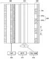
도 4는 본 발명의 제1실시예에 따른 2차원 겸용 입체 영상 표시 장치의 개략적인 구성도를 나타낸 것이다.4 is a schematic configuration diagram of a two-dimensional dual-dimensional image display device according to a first embodiment of the present invention.
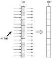
도 5a는 제1 편광 빔이 제1실시예에 따른 2차원 겸용 입체 영상 표시 장치에 구비된 스위칭 베리어 유닛에 입사되었을 때의 등가화된 베리어 유닛을 도시한 것이다.FIG. 5A illustrates an equivalent barrier unit when the first polarized beam is incident on the switching barrier unit included in the two-dimensional stereoscopic image display according to the first embodiment.
도 5b는 제2 편광 빔이 제1실시예에 따른 2차원 겸용 입체 영상 표시 장치에 구비된 스위칭 베리어 유닛에 입사되었을 때의 등가화된 베리어 유닛을 도시한 것이다.FIG. 5B illustrates an equivalent barrier unit when the second polarized beam is incident on the switching barrier unit included in the two-dimensional stereoscopic image display according to the first embodiment.
도 6은 본 발명에 따른 2차원 겸용 입체 영상 표시 장치에서 제1필드 영상신호와 제2필드 영상신호가 순차적으로 입력시 3차원 영상이 구현되는 과정을 다이아 그램으로 나타낸 것이다.FIG. 6 is a diagram illustrating a process of implementing a three-dimensional image when the first field image signal and the second field image signal are sequentially input in the two-dimensional dual-dimensional display device according to the present invention.
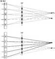
도 7a는 본 발명의 제1실시예에 따른 2차원 겸용 입체 영상 표시 장치에서 제1편광 방향을 가지는 제1필드 영상이 좌안과 우안으로 분리되어 3차원 영상이 표시되는 원리를 설명하기 위한 도면이다.FIG. 7A is a diagram for describing a principle of displaying a three-dimensional image by separating a first field image having a first polarization direction into a left eye and a right eye in a two-dimensional dual-dimensional stereoscopic image display according to a first embodiment of the present invention. .
도 7b는 본 발명의 제1실시예에 따른 2차원 겸용 입체 영상 표시 장치에서 제2편광 방향을 가지는 제2필드 영상이 좌안과 우안으로 분리되어 3차원 영상이 표시되는 원리를 설명하기 위한 도면이다.FIG. 7B is a view for explaining a principle of displaying a 3D image by dividing a second field image having a second polarization direction into a left eye and a right eye in a 2D dual-dimensional stereoscopic image display device according to a first embodiment of the present invention. .
도 8은 본 발명의 제1실시예에 따른 2차원 겸용 입체 영상 표시 장치에서 2차원 영상이 표시되는 원리를 설명하기 위한 도면이다.8 is a view for explaining the principle of displaying a two-dimensional image in the two-dimensional dual-dimensional display device according to the first embodiment of the present invention.
도 9는 본 발명의 제2실시예에 따른 2차원 겸용 입체 영상 표시 장치의 개략적인 구성도를 도시한 것이다.9 is a schematic structural diagram of a two-dimensional dual-dimensional image display device according to a second embodiment of the present invention.
도 10a 및 도 10b는 본 발명의 제2실시예에 따른 2차원 겸용 입체 영상 표시 장치에 구비된 스위칭 베리어 유닛에 제1 편광빔과 제2 편광빔이 입사되었을 때의 등가화된 베리어 유닛을 각각 도시한 것이다.10A and 10B illustrate an equivalent barrier unit when a first polarizing beam and a second polarizing beam are respectively incident on a switching barrier unit provided in a two-dimensional dual-dimensional display device according to a second embodiment of the present invention. It is shown.
도 11은 본 발명의 제2실시예에 따른 2차원 겸용 입체 영상 표시 장치에서 2차원 영상이 표시되는 원리를 설명하기 위한 도면이다.11 is a view for explaining the principle of displaying a two-dimensional image in the two-dimensional dual-dimensional image display apparatus according to a second embodiment of the present invention.
<도면 중 주요 부분에 대한 설명><Description of main part of drawing>
100,200...디스플레이 패널, 108,208...구동부100,200 ... display panel, 108,208 ...
110,210...편광 변환 소자, 112,212...동기부110,210 ... polarization conversion element, 112,212
120,220...스위칭 베리어 유닛, 120a..제1 편광부120,220 ... switching barrier unit, 120a ... first polarizer
120b...제2 편광부, 114,214...전압 구동원120b ... second polarizer, 114,214 voltage driving source
222a...위상 지연부, 222b...투과부222a ... phase delay, 222b ... transmissive
222...부분 위상 지연판, 224...편광판222 ... partial phase retarder, 224 ... polarizer
본 발명은 입체 영상 표시 장치에 관한 것으로, 보다 상세하게는 해상도 저하 없이 입체 영상을 표시하고, 보다 저렴한 비용으로 생산 가능한 2차원 겸용 입체 영상 표시 장치에 관한 것이다.BACKGROUND OF THE INVENTION 1. Field of the Invention The present invention relates to a stereoscopic image display device, and more particularly, to a two-dimensional combined stereoscopic image display device capable of displaying a stereoscopic image without lowering resolution and producing at a lower cost.
일반적으로 3차원 영상은 사람의 두 눈을 통한 스테레오 시각의 원리에 의해 이루어지는데, 두 눈이 약 65mm 정도 떨어져서 존재하기 때문에 나타나는 양안시차(binocular parallax)가 입체감의 가장 중요한 요인이라고 할 수 있다. 3차원 영상 디스플레이에는 안경을 이용한 디스플레이와 무안경 방식의 디스플레이가 있으며, 무안경 방식의 디스플레이는 안경을 사용하지 않고 좌우 영상을 분리하여 3차원 영상을 얻는 것이다. 무안경 방식에는 예를 들어 패럴렉스 베리어 방식(parallax barrier)과 렌티큘러(lenticular) 방식이 있다.In general, three-dimensional images are based on the principle of stereo vision through two eyes of a person. The binocular parallax, which appears because the eyes are about 65 mm apart, is the most important factor of the stereoscopic sense. The three-dimensional image display includes a display using glasses and a display without glasses, and the display without glasses uses a three-dimensional image by separating the left and right images without using glasses. For example, there is a parallax barrier and a lenticular method.
패럴랙스 베리어 방식이나 렌티큘라 방식 디스플레이 패널 앞 또는 뒤에 특수한 광학판, 예를 들어 베리어나 렌티큘라 렌즈 등을 위치시켜 서로 다른 시점의 영상들을 공간적으로 적절히 분리시킨다는 점에서 그 기본적인 원리는 유사하다. 이 때 서로 다른 시점의 영상들이 분리되면서 특정한 시역을 형성하게 되는데, 관 찰자의 두 눈이 해당 시역 안에 위치할 때에만 입체 영상을 제대로 관찰할 수 있다.The basic principle is similar in that a special optical plate, such as a barrier or a lenticular lens, is placed in front of or behind a parallax barrier or lenticular display panel to appropriately separate images from different viewpoints. At this time, images from different viewpoints are separated to form a specific gaze. A stereoscopic image can be properly observed only when two eyes of an observer are located in the gazebo.
패럴렉스 베리어 방식은 좌우 양안이 각각 보아야 할 화상을 교대로 세로 무늬 모양으로 인쇄 또는 사진으로 인화하여 이것을 극히 가느다란 세로 격자열 즉, 베리어를 이용하여 보는 것이다. 이렇게 함으로써, 좌안에 들어올 세로 무늬 화상과 우안에 들어올 세로 무늬 화상이 베리어에 의해 배분되어 좌안과 우안으로 각각 다른 시점(view point)의 화상이 보임으로써 입체 영상으로 보이는 것이다.The parallax barrier method is to print images or print them in a vertical pattern alternately to be viewed by both left and right eyes, and to view them using an extremely thin vertical grid, that is, a barrier. By doing so, the vertical pattern image to enter the left eye and the vertical pattern image to enter the right eye are distributed by the barrier so that images of different view points are shown to the left eye and the right eye, respectively, so that the stereoscopic image is seen.
미국특허 5,315,377호에 개시된 패럴렉스 베리어 방식에 의하면, 도 1에 도시된 바와 같이 관찰자의 좌안(LE)과 우안(RE)에 대응하는 좌안 화상 정보(Ln) 및 우안 화상 정보(Rn)를 가진 액정 패널(3) 앞에 세로 격자 모양의 개구(5)와 마스크(7)를 갖는 패럴렉스 베리어(10)를 배치하고, 상기 패럴렉스 베리어(10)의 개구(5)를 통해 영상을 분리한다. 상기 액정 패널(3)에는 좌안에 입력될 화상정보(Ln)와 우안에 입력될 화상정보(Rn)가 수평 방향을 따라 교대로 배열되어 있다.According to the parallax barrier method disclosed in US Pat. No. 5,315,377, a liquid crystal having left eye image information Ln and right eye image information Rn corresponding to the left eye LE and right eye RE of the observer as shown in FIG. A
예를 들어, 좌안 화상 정보(Ln)를 가진 화소와 우안 화상 정보(Rn)를 가진 화소가 한 세트로 되고, 상기 개구(5)를 중심으로 좌우의 화소가 각각 다른 시점의 화소가 되어 입체 영상을 구현할 수 있는 것이다. 예를 들어, 제1 좌안 화상이 좌안에, 제1 우안 화상이 우안에 각각 들어가고, 제2 좌안 화상이 좌안에, 제2 우안 화상이 우안에 각각 들어가며, 동일한 방식으로 좌우의 화소가 각각 대응되는 좌안과 우안에 들어간다.For example, the pixel having the left eye image information Ln and the pixel having the right eye image information Rn are one set, and the left and right pixels centering on the opening 5 become pixels at different viewpoints, respectively. Can be implemented. For example, the first left eye image enters the left eye, the first right eye image enters the right eye, the second left eye image enters the left eye, the second right eye image enters the right eye, respectively, and the left and right pixels correspond in the same manner. Enter the left and right eyes.
이러한 방식에 의하면, 상기 개구(5)를 통해서 화상이 형성되는 한편 상기 마스크(7)를 통해서는 화상이 차단되기 때문에, 도 2에 도시된 바와 같이 좌안 화상(L)은 예를 들어 홀수열 화상만으로 구성되는 한편, 우안 화상(R)은 예를 들어, 짝수열 화상만으로 구성된다.According to this method, since an image is formed through the
따라서, 디스플레이 전체적으로 해상도가 떨어지고, 3차원 영상의 밝기가 저하되는 문제점이 있다.Therefore, there is a problem in that the resolution of the entire display is lowered and the brightness of the 3D image is lowered.
시역 분리 수단으로 이용되는 베리어는 보통 투명 필름이나 유리판 위에 주기적으로 반복되는 줄무늬 패턴을 인쇄해 제작하지만, 전기적인 방법으로 베리어를 구현하는 방법도 있다. 이 경우 도 3에서와 같이 영상을 디스플레이하기 위한 디스플레이 패널(46) 전면에 베리어로 동작하기 위한 LCD 패널(28)이 하나 더 구비된다. 이와 같은 액정 베리어 방식은 베리어의 형태를 능동적으로 조절할 수 있으나, 디스플레이 패널 이외에 LCD 패널을 더 구비하여야 하므로 공정이 복잡하고 제조 단가가 상승되는 단점이 있다.Barriers used as separation means are usually produced by printing a pattern of stripes that are periodically repeated on a transparent film or glass plate, but there are also methods of implementing barriers by an electric method. In this case, an
따라서, 본 발명은 2차원 영상과 3차원 영상을 선택적으로 표시할 수 있고, 해상도의 저하 없이 입체 영상을 표시하며, 제작이 용이한 2차원 겸용 입에 영상 표시 장치를 제공하는데 목적이 있다.Accordingly, an object of the present invention is to provide a two-dimensional image and a three-dimensional image, to display a three-dimensional image without deterioration of resolution, and to provide an image display apparatus in a two-dimensional combined mouth that is easy to manufacture.
상기한 목적을 달성하기 위하여 본 발명에 따른 2차원 겸용 입체 영상 표시장치는, 입력된 영상 신호에 따라 공간 변조하여 영상을 형성하는 디스플레이 패널; 상기 영상 신호에 동기하여 인가되는 전압에 따라 입사 빔의 편광 방향을 변환 시키는 편광 변환 소자; 제1 편광 방향의 제1 편광부와 제2 편광 방향의 제2 편광부가 교대로 배열된 것으로 상기 편광 변환 소자를 통과한 빔을 편광 방향에 따라 상기 제1 편광부 및 제2 편광부 중 적어도 하나를 통해 통과시키는 스위칭 베리어 유닛;을 포함하는 것을 특징으로 한다.In order to achieve the above object, a two-dimensional dual-dimensional display device according to the present invention, a display panel for spatially modulating in accordance with the input image signal to form an image; A polarization conversion element for converting a polarization direction of an incident beam according to a voltage applied in synchronization with the image signal; At least one of the first and second polarization parts according to the polarization direction of the beam passing through the polarization conversion element, wherein the first polarization part in the first polarization direction and the second polarization part in the second polarization direction are alternately arranged. It characterized in that it comprises a; switching barrier unit passing through.
상기 목적을 달성하기 위해 본 발명에 따른 2차원 겸용 입체 영상 표시 장치는, 입력된 영상 신호에 따라 공간 변조하여 영상을 형성하는 디스플레이 패널; 상기 영상 신호에 동기하여 인가되는 전압에 따라 입사 빔의 편광 방향을 변환시키는 편광 변환 소자; 상기 편광 변환 소자로부터 출력된 빔의 위상을 지연시키는 위상 지연부와 편광 변환 소자로부터 출력된 빔을 통과시키는 투과부가 교대로 배열된 부분 위상 지연판과, 상기 부분 위상 지연판 다음에 배치된 편광판을 구비한 스위칭 베리어 유닛;을 포함하는 것을 특징으로 한다.In order to achieve the above object, a two-dimensional dual-dimensional display device according to the present invention, a display panel for spatially modulating according to the input image signal to form an image; A polarization conversion element for converting the polarization direction of the incident beam according to the voltage applied in synchronization with the image signal; A phase retarder for retarding the phase of the beam output from the polarization conversion element and a partial phase retardation plate in which alternating transmission portions for passing the beam output from the polarization conversion element are alternately arranged, and a polarizing plate disposed after the partial phase retardation plate. It is characterized in that it comprises a; switching barrier unit provided.
상기 편광 변환 소자에 전압을 인가하는 전압 구동원을 구비하는 것을 특징으로 한다.And a voltage driving source for applying a voltage to the polarization converting element.
상기 제1 편광부와 제2 편광부는 서로 직교하는 직선 편광 방향을 가지는 것이 바람직하다.It is preferable that the said 1st polarizing part and the 2nd polarizing part have a linear polarization direction orthogonal to each other.
상기 제1 편광 방향 또는 제2 편광 방향이 상기 디스플레이 패널로부터 출력된 영상빔의 편광 방향과 같은 것이 바람직하다.Preferably, the first polarization direction or the second polarization direction is the same as the polarization direction of the image beam output from the display panel.
상기 디스플레이 패널은 LCD 또는 FLCD인 것을 특징으로 한다.The display panel is characterized in that the LCD or FLCD.
상기 편광 변환 소자는 입사 빔의 편광 방향을 45도 편광 방향을 갖도록 하여 2차원 영상을 표시하는 것을 특징으로 한다.The polarization conversion element may display a two-dimensional image by making the polarization direction of the incident beam have a 45 degree polarization direction.
상기 이웃하는 제1 편광부 사이 또는 이웃하는 제2 편광부 사이의 간격 피치(p)는 하기의 조건식을 만족시키는 것을 특징으로 한다.An interval pitch p between the neighboring first polarizers or the neighboring second polarizers may satisfy the following conditional expression.
<조건식><Conditional expression>

여기서, m = e/i이고, e는 좌안과 우안 사이의 평균 거리이며, i는 디스플레이 패널의 픽셀 피치를 나타낸다.Where m = e / i, e is the average distance between the left eye and the right eye, and i represents the pixel pitch of the display panel.
이하, 본 발명의 바람직한 실시예에 따른 2차원 겸용 입체 영상 표시 장치에 대해 첨부된 도면들을 참조하여 상세히 설명하기로 한다.Hereinafter, a 2D combined stereoscopic image display device according to an exemplary embodiment of the present invention will be described in detail with reference to the accompanying drawings.
도 4를 참조하면, 본 발명에 따른 입체 영상 표시장치는 영상을 형성하는 디스플레이 패널(100)과, 디스플레이 패널(100)로부터 출력된 영상 빔의 편광 방향을 인가된 전압에 따라 변환하는 편광 변환 소자(110)와, 상기 편광 변환 소자(110)를 통과한 빔을 편광 방향에 따라 통과시키거나 차단하기 위한 패턴으로 형성된 스위칭 베리어 유닛을 포함한다.Referring to FIG. 4, a stereoscopic image display device according to the present invention includes a
도 4는 본 발명의 제1 실시예에 따른 입체 영상 표시장치를 도시한 것으로, 디스플레이 패널(100)은 편광 의존형인 LCD(Liquid Crystal Display) 또는 FLCD(Ferro Liquid Crystal Display)인 것이 바람직하며, 투과형 또는 반사형일 수 있다. 디스플레이 패널(100)은 구체적으로 제1 편광판(101), 제1글라스판(102), TFT 구동부(103)에 의해 구동되는 TFT(104), 제2글라스판(105) 및 제2편광판(106)을 포함하여 구성된다.4 illustrates a stereoscopic image display device according to a first embodiment of the present invention, wherein the
상기 편광 변환 소자(110)는 다양한 방법으로 구현 가능하나, 예를 들어 액정에 인가하는 전압에 따라 그 편광 방향이 변환되는 액정 편광 변환기로 구성될 수 있다. 예를 들어, 편광 변환 소자(110)에 전압 구동원(114)로부터 제1전압(V1)이 입력될 때 입사빔의 편광 방향이 그대로 유지되어 통과되고, 제2전압(V2)으로 입력될 때 입사빔의 편광 방향이 90도 변환되고, 제3전압(V3)으로 입력될 때 입사빔의 편광 방향이 45도 변환된다. 상기 편광 변환 소자(110)에는 동기부(112)에 의해 디스플레이 패널(100)에서의 영상 출력과 동기되어 전압이 인가된다.The
상기 스위칭 베리어 유닛(120)은 제1 편광 방향을 가지는 제1 편광부(120a)와 제2 편광 방향을 가지는 제2 편광부(120b)가 교대로 배열된 패턴으로 구성될 수 있다. 상기 제1 편광 방향과 제2 편광 방향은 서로 직교하는 직선 편광인 것이 바람직하며, 예를 들어 제1 편광 방향은 상기 디스플레이 패널(100)로부터 출사되는 빔의 편광 방향과 같고 제2 편광 방향은 상기 디스플레이 패널(100)로부터 출사되는 빔의 편광 방향에 직교하는 방향을 갖는다. 디스플레이 패널(100)에서 형성된 영상빔이 상기 스위칭 베리어 유닛(120)을 통과할 때 제1 편광부(120a)를 통해 통과되고 제2 편광부(120b)에 의해 차단되거나, 제1 편광부(120a)에 의해 차단되고 제2 편광부(120b)를 통해 통과됨으로써 해상도의 저하 없이 3차원 영상을 구현할 수 있다.The switching
상기 이웃하는 제1 편광부(120a) 사이 또는 이웃하는 제2 편광부(120b) 사이의 간격 피치(p)는 하기의 수학식에 의해 결정된다. An interval pitch p between the neighboring

여기서 m = e/i이고, e는 좌안과 우안 사이의 평균 거리로서 65 mm일 수 있으며, i는 디스플레이 패널의 픽셀 피치를 나타낸다. 상기 수학식 1에 따른 피치(p)는 기존의 고정식 베리어 방식의 입체 영상 표시 장치에서의 베리어 사이의 피치와 동일하게 적용된다. 그리고, 상기 수학식은 일반적인 2 시점의 베리어 구조에 적용된다.Where m = e / i, e may be 65 mm as the average distance between the left and right eyes, and i represents the pixel pitch of the display panel. The pitch p according to Equation 1 is equally applied to the pitch between the barriers in the conventional fixed barrier type stereoscopic image display device. The above equation is applied to a barrier structure of two general time points.
제1 실시예에 따른 3차원 영상 디스플레이 장치에서 3차원 영상이 표시되는 작용에 대해 설명하면 다음과 같다.An operation of displaying a 3D image in the 3D image display apparatus according to the first embodiment will be described below.
도 5a를 참조하면 디스플레이 패널(100)에 입력되는 한 프레임의 영상 신호는 제1 필드영상신호와 제2필드영상신호로 구성되고, 제1 필드영상신호와 제2 필드영상신호가 시간 순차적으로 디스플레이 패널(100)에 입력된다. 상기 디스플레이 패널(100)에서 출력되는 제1 필드 영상 빔이 제1 편광 방향을 가질 때, 예를 들어 S 편광 빔일 때, 상기 편광방향 변환 소자(110)에 상기 제1 필드 영상에 동기되어 V1의 전압이 인가되면 상기 제1 필드 영상 빔은 편광 방향이 변하지 않고 편광방향 변환 소자(110)를 통과하여 스위칭 베리어 유닛(120)에 입사된다. 제1 편광 빔은 스위칭 베리어 유닛(120)의 제1 편광부(120a)를 통해 통과되는 한편 제2 편광부(120b)에 의해 차단되어 결과적으로 120'로 표시된 등가화된 베리어와 같이 작용한다.Referring to FIG. 5A, a video signal of one frame input to the
이어서, 도 5b를 참조하면 상기 디스플레이 패널(100)에서 제2 필드 영상 빔이 출력될 때 상기 편광방향 변환 소자(110)에 상기 제2 필드 영상에 동기되어 V2의 전압이 인가되면 상기 제2 필드 영상 빔은 편광 방향이 제2 편광 방향, 예를 들어 P 편광 빔으로 변환되어 상기 스위칭 베리어 유닛(120)에 입사된다. 제2 편광 빔은 스위칭 베리어 유닛(120)의 제1 편광부(120a)에 의해 차단되고 제2 편광부(120b)를 통해 통과되어 결과적으로 120"로 표시된 등가화된 베리어와 같이 작용한다. 이와 같이 스위칭 베리어 유닛(120)은 입사빔의 편광 방향에 따라 빔을 통과시키는 개구부와 빔을 차단시키는 비개구부가 시간 순차적으로 반전되면서 스위칭됨으로써 3차원 영상을 해상도의 저하없이 구현할 수 있도록 한다.Subsequently, referring to FIG. 5B, when the second field image beam is output from the
도 6은 제1 필드 영상이 스위칭 베리어 유닛(120)의 제1 편광부(120a)를 통과하여 좌안 영상과 우안 영상으로 분리되고, 제2 필드 영상이 스위칭 베리어 유닛(120)의 제2 편광부(120b)를 통과하여 좌안 영상과 우안 영상으로 분리되는 것을 도표화하여 보여준 것으로 3차원 영상이 해상도의 저하 없이 구현됨을 보여 준다.FIG. 6 illustrates that the first field image passes through the
도 7a는 편광 변환 소자에서 편광 방향 변화 없이 통과된 제1 편광 방향을 가지는 제1 필드 영상이 등가화된 스위칭 베리어 유닛(120')을 통해 좌안 영상과 우안 영상으로 분리되는 경우를 도시한 것으로, 제1 필드 영상에 대해서는 좌안으로 짝수열 좌안 영상(Lf1), 우안으로 홀수열 우안 영상(Rf1)이 맺힌다. 여기서, 실선은 스위칭 베리어 유닛의 개구부를 통해 통과하는 빔을, 점선은 스위칭 베리어 유닛의 비개구부를 통해 차단되는 빔을 나타낸 것이며, 좌안 영상과 우안 영상을 구별하여 도시하였다.FIG. 7A illustrates a case in which a first field image having a first polarization direction passed through the polarization conversion element without changing the polarization direction is separated into a left eye image and a right eye image through an equivalent
도 7b는 편광 변환 소자에서 편광 방향이 제2 편광 방향으로 변환되어 등가화된 스위칭 베리어 유닛(120")을 통해 실선으로 표시된 제2 필드 좌안 영상(Lf2)과 제2 필드 우안 영상(Rf2)으로 분리되어 각각 좌안과 우안에 맺히는 경우를 도시한 것이다. 제2 필드 영상에 대해서는 좌안으로 홀수열 좌안 영상이, 우안으로 짝수열 우안 영상이 맺힌다.FIG. 7B illustrates a second field left eye image Lf2 and a second field right eye image Rf2 indicated by solid lines through the
이와 달리, 제1 필드 영상에 대해서는 좌안으로 홀수열 좌안 영상이, 우안으로 짝수열 우안 영상이 맺히도록 하고, 제2 필드 영상에 대해서는 좌안으로 짝수열 좌안 영상이, 우안으로 홀수열 우안 영상이 맺히도록 하는 것도 가능하다.In contrast, an odd-numbered left eye image is formed in the left eye for the first field image, an even-numbered right eye image is formed in the right eye, an even-numbered left eye image is formed in the left eye, and an odd-numbered right eye image is formed in the right eye. It is also possible to do so.
제1 필드 영상과 제2 필드 영상은 사람의 눈이 감지할 수 없는 빠른 속도로 순차적으로 출력되어 2차원 영상에 비해 해상도의 저하 없이 3차원 영상을 볼 수 있다. 일반적으로 제1 필드 영상과 제2 필드 영상의 주기가 1/120 초 이하일 때 사람의 눈이 Flickering을 감지할 수 없는 것으로 알려져 있으며, 이 정도의 동작 속도는 FLC(Ferroelectric Liquid Crystal)나 OCB(Optical Compensated Bend) 등의 특수한 액정을 이용하여 구현 가능하다.The first field image and the second field image are sequentially output at a high speed that cannot be detected by the human eye, so that the 3D image can be viewed without degrading the resolution compared to the 2D image. In general, it is known that the human eye cannot detect flickering when the period of the first field image and the second field image is less than 1/120 second, and the operation speed is about 200 ° C (Ferroelectric Liquid Crystal) or OCB (Optical). It can be implemented using a special liquid crystal such as Compensated Bend.
한편, 본 발명에 따른 입체 영상 디스플레이 장치에서는 3차원 영상과 아울러 2차원 영상이 표시된다. 그 작용 효과에 대해 살펴보면, 상기 디스플레이 패널(100)에서 출력된 제1 편광 빔이 편광 변환 소자(110)에 입사되고, 상기 편광 변환 소자(110)에 V3 전압이 인가되면, 빔의 편광 방향이 45도 편광 방향을 가지도록 변환되어 스위칭 베리어 유닛(120)에 입사된다. 도 9는 45도 편광 방향을 가지는 빔이 스위칭 베리어 유닛(120)에 입사되는 경우를 도시한 것으로 45도 편광 방향을 가지는 빔은 제1 편광부(120a)와 제2 편광부(120b) 양쪽을 통과한다. 이때 입사 빔의 일부는 통과되지 못하고 손실되지만 제1 및 제2 편광부(120a)(120b) 양쪽을 통해 통과되므로 등가화된 스위칭 베리어 유닛(120"') 전체를 통해 출력된다. 따라서, 디스플레이 패널에 의해 형성된 영상이 좌안 영상과 우안 영상으로 분리되지 않고 2차원 영상을 형성한다.Meanwhile, in the stereoscopic image display apparatus according to the present invention, a two-dimensional image is displayed as well as a three-dimensional image. Referring to the operation effect, when the first polarization beam output from the
상술한 바와 같이 디스플레이 패널(100)에서 출력되는 제1 필드영상과 제2 필드영상에 동기되어 시간 순차적으로 인가되는 제1 전압(V1)과 제2 전압(V2)에 따라 구동되는 편광 변환 소자(110)를 통해 입사빔의 편광 방향이 변환되어 스위칭 베리어 유닛(120)에 입사됨으로써 3차원 영상이 2차원 영상에 비해 해상도의 저하 없이 구현될 수 있다. 상기 스위칭 베리어 유닛(120)은 입사 빔의 편광 방향에 따라 베리어부가 스위칭되는 작용을 한다.As described above, the polarization conversion element driven according to the first voltage V1 and the second voltage V2 which are sequentially applied in time in synchronization with the first field image and the second field image output from the display panel 100 ( The polarization direction of the incident beam is converted through the 110 to be incident on the
다음, 본 발명의 제2 실시예에 따른 입체 영상 디스플레이 장치는 도 9를 참조하면 영상을 형성하는 디스플레이 패널(200)과, 상기 영상 빔의 편광 방향을 변환하는 편광 변환 소자(210)와, 상기 편광 변환 소자(210)를 통과한 빔의 편광 방향에 따라 빔을 통과시키거나 차단하는 패턴을 가지는 스위칭 베리어 유닛(220)을 포함한다.Next, referring to FIG. 9, the stereoscopic image display apparatus according to the second embodiment of the present invention includes a
상기 디스플레이 패널(200)는 구동부(208)에 의해 공간 변조되어 영상을 형성하는 것으로 예를 들어 LCD 또는 FLCD로 구성될 수 있다. 상기 편광 변환 소자(210)는 동기부(212)를 통해 상기 구동부(208)에 동기되어 전압 구동원(214)으로부터 인가되는 전압에 따라 입사빔의 편광 방향을 변환한다. 상기 디스플레이 패널 (200)과 편광 변환 소자(210)에 대한 구체적인 구조 및 작용 효과는 제1실시예에서의 디스플레이 패널(100)과 편광 변환 소자(110)와 실질적으로 동일하므로 여기서는 그 상세한 설명을 생략하기로 한다.The
상기 스위칭 베리어 유닛(220)은 위상 지연부(222a)와 투과부(222b)가 교대로 반복되어 배열된 부분 위상 지연판(222)과 편광판(224)을 포함한다. 이웃하는 위상 지연부(222a) 사이의 간격 피치 및 이웃하는 투과부 사이의 간격 피치(p)는 상기 수학식 1에 따라 설계될 수 있다. 상기 위상 지연부(222a)는 1/2 파장판으로서 상기 편광 변환 소자(210)를 통과한 빔의 편광 방향을 90도 지연시킴으로써 S편광 빔을 P편광 빔으로 또는 P편광 빔을 S편광 빔으로 변환한다. 이와 동시에 상기 투과부(222b)를 통과하는 빔은 편광 방향의 변화 없이 투과된다. 결과적으로 상기 부분 위상 지연판(222)을 통과한 빔은 제1편광 빔과 제2 편광 빔이 혼합되어 존재하고, 편광판(224)의 편광 방향에 따라 제1 편광 빔 및 제2 편광 빔 중 어느 한 빔이 편광판(224)을 통과한다.The switching
도 10a 및 도 10b는 상기 스위칭 베리어 유닛(220)의 스위칭 작용을 설명하기 위한 도면이다. 상기 편광 변환 소자(210)를 통해 제1 편광 빔이 부분 위상 지연판(222)에 입사되면 위상 지연부(222a)를 통해서 제1 편광 빔이 제2 편광 빔으로 변환되고, 투과부(222b)를 통해서는 제1 편광 빔이 그대로 통과된다. 이어서, 편광 변환 소자(210)를 통해 제2 편광 빔이 부분 위상 지연판(222)에 입사되면 위상 지연부(222a)를 통해 제2 편광 빔이 제1 편광 빔으로 변환되고, 투과부(222b)를 통해서는 제2 편광 빔이 그대로 통과된다. 제1 편광 빔이 입사되었을 때와 제2 편광 빔 이 입사되었을 때를 비교해 보면 제1 편광 빔과 제2 편광 빔의 위치가 서로 역전되고, 결과적으로 편광판(224)의 편광 방향에 따라 통과하는 편광 빔의 위치가 서로 달라지게 된다. 예를 들어 상기 편광판(224)이 제1 편광 방향을 가질 때 제1 편광 빔만이 통과되고 제2 편광 빔은 차단되며, 통과되는 제1 편광 빔의 위치가 시간 순차적으로 스위칭됨으로써 스위칭 베리어의 기능을 하게 된다. 이러한 작용은 등가화된 스위칭 베리어 유닛(220')(220")을 통해 쉽게 이해될 수 있다.10A and 10B are diagrams for describing a switching action of the
도 11은 제2 실시예에 따른 입체 영상 표시 장치에서 2차원 영상이 구현될 때 스위칭 베리어 유닛(220)의 작용을 설명하기 위한 도면이다.FIG. 11 is a diagram for describing an operation of the
디스플레이 패널(200)에서 2차원 영상이 형성될 때 편광 변환 소자(210)에서 제3 전압(V3)이 인가되고, 편광 변환 소자(210)에 의해 영상 빔의 편광 방향이 45도로 변환되어 스위칭 베리어 유닛(220)에 입사된다. 45도 편광 방향을 가지는 빔이 위상 지연부(222a)와 투과부(222b) 양쪽을 통해 통과된 다음 편광판(224)을 통해 통과된다. 결과적으로 등가화된 스위칭 베리어 유닛(220"')과 같이 스위칭 베리어 유닛(220) 전체를 통해 영상이 통과되므로 좌안 영상과 우안 영상으로 분리되지 않고 2차원 영상이 구현된다.When the 2D image is formed in the
본 발명에서는 필요에 따라 2차원 모드와 3차원 모드를 선택적으로 구현할 수 있으며, 3차원 영상을 2차원 영상에 비해 해상도의 저하 없이 구현할 수 있다.In the present invention, the two-dimensional mode and the three-dimensional mode can be selectively implemented as needed, and the three-dimensional image can be implemented without degrading the resolution as compared to the two-dimensional image.
상기한 바와 같이 본 발명에 따른 입체 영상 표시장치는 간단한 편광 소자들의 조합과 시분할 방식을 사용해 저비용으로 입체 영상의 수평 해상도 저하 없이 3 차원 영상을 구현할 수 있다. 또한, 편광 변환 소자의 전압을 조절하여 3차원 영상뿐만 아니라 2차원 영상을 같이 디스플레이할 수 있는 이점이 있다.As described above, the stereoscopic image display device according to the present invention can implement a 3D image without lowering the horizontal resolution of the stereoscopic image at low cost by using a simple combination of polarizing elements and a time division method. In addition, there is an advantage that can display a two-dimensional image as well as a three-dimensional image by adjusting the voltage of the polarization conversion element.
상기한 실시예들은 예시적인 것에 불과한 것으로, 당해 기술분야의 통상을 지식을 가진 자라면 이로부터 다양한 변형 및 균등한 타 실시예가 가능하다. 따라서, 본 발명의 진정한 기술적 보호범위는 하기의 특허청구범위에 기재된 발명의 기술적 사상에 의해 정해져야만 할 것이다.The above embodiments are merely exemplary, and various modifications and equivalent other embodiments are possible to those skilled in the art. Therefore, the true technical protection scope of the present invention will be defined by the technical spirit of the invention described in the claims below.
Claims (14)
Translated fromKorean

Priority Applications (5)
| Application Number | Priority Date | Filing Date | Title |
|---|---|---|---|
| KR1020050055416AKR20060135450A (en) | 2005-06-25 | 2005-06-25 | 2-D combined stereoscopic display |
| US11/395,306US7728789B2 (en) | 2005-06-25 | 2006-04-03 | 2D and 3D image display apparatus |
| EP06252873AEP1737250A3 (en) | 2005-06-25 | 2006-06-02 | Autostereoscopic display with an enhanced horizontal resolution |
| CNB2006100930561ACN100429560C (en) | 2005-06-25 | 2006-06-19 | 2D and 3D image display devices |
| JP2006173781AJP5426067B2 (en) | 2005-06-25 | 2006-06-23 | Two-dimensional stereoscopic display device |
Applications Claiming Priority (1)
| Application Number | Priority Date | Filing Date | Title |
|---|---|---|---|
| KR1020050055416AKR20060135450A (en) | 2005-06-25 | 2005-06-25 | 2-D combined stereoscopic display |
Publications (1)
| Publication Number | Publication Date |
|---|---|
| KR20060135450Atrue KR20060135450A (en) | 2006-12-29 |
Family
ID=37009148
Family Applications (1)
| Application Number | Title | Priority Date | Filing Date |
|---|---|---|---|
| KR1020050055416ACeasedKR20060135450A (en) | 2005-06-25 | 2005-06-25 | 2-D combined stereoscopic display |
Country Status (5)
| Country | Link |
|---|---|
| US (1) | US7728789B2 (en) |
| EP (1) | EP1737250A3 (en) |
| JP (1) | JP5426067B2 (en) |
| KR (1) | KR20060135450A (en) |
| CN (1) | CN100429560C (en) |
Cited By (3)
| Publication number | Priority date | Publication date | Assignee | Title |
|---|---|---|---|---|
| KR100908724B1 (en)* | 2007-10-22 | 2009-07-22 | 삼성모바일디스플레이주식회사 | Barrier device and electronic imaging device including the same |
| KR20120069463A (en)* | 2010-12-20 | 2012-06-28 | 엘지디스플레이 주식회사 | Device for displaying 2d/3d display-convertible image |
| US8264626B2 (en) | 2009-08-21 | 2012-09-11 | Samsung Display Co., Ltd. | Stereoscopic image display device |
Families Citing this family (45)
| Publication number | Priority date | Publication date | Assignee | Title |
|---|---|---|---|---|
| KR100728113B1 (en)* | 2005-10-20 | 2007-06-13 | 삼성에스디아이 주식회사 | Stereoscopic Display and Driving Method |
| KR101299728B1 (en)* | 2007-01-24 | 2013-08-22 | 삼성전자주식회사 | High efficient 2D-3D switchable display apparatus |
| KR100846707B1 (en)* | 2007-02-27 | 2008-07-16 | 삼성에스디아이 주식회사 | Electronic imaging equipment |
| US20120268451A1 (en)* | 2007-06-25 | 2012-10-25 | Industrial Technology Research Institute | Three-dimensional (3d) display |
| KR20090018528A (en)* | 2007-08-17 | 2009-02-20 | 삼성전자주식회사 | 2D / 3D image compatible display device and its driving method |
| KR101291799B1 (en)* | 2009-05-29 | 2013-07-31 | 엘지디스플레이 주식회사 | Stereoscopic Image Display Device |
| JP2011107589A (en)* | 2009-11-20 | 2011-06-02 | Sony Corp | Stereoscopic display apparatus |
| JP5353770B2 (en)* | 2010-03-05 | 2013-11-27 | カシオ計算機株式会社 | Stereoscopic image observation apparatus, stereoscopic video display apparatus, and program |
| CN102193204B (en)* | 2010-03-11 | 2016-08-31 | 京东方科技集团股份有限公司 | Three-dimensional display and three-dimensional display system |
| CN101799599A (en)* | 2010-03-18 | 2010-08-11 | 友达光电股份有限公司 | Stereoscopic display and display method thereof |
| CN102253495B (en)* | 2010-05-18 | 2013-10-30 | 京东方科技集团股份有限公司 | Dual-view display equipment and system |
| CN101852922A (en)* | 2010-05-24 | 2010-10-06 | 友达光电股份有限公司 | Display device capable of switching two-dimensional and three-dimensional display modes |
| US8615622B2 (en) | 2010-06-23 | 2013-12-24 | International Business Machines Corporation | Non-standard I/O adapters in a standardized I/O architecture |
| US8683108B2 (en) | 2010-06-23 | 2014-03-25 | International Business Machines Corporation | Connected input/output hub management |
| US8677180B2 (en) | 2010-06-23 | 2014-03-18 | International Business Machines Corporation | Switch failover control in a multiprocessor computer system |
| US8918573B2 (en) | 2010-06-23 | 2014-12-23 | International Business Machines Corporation | Input/output (I/O) expansion response processing in a peripheral component interconnect express (PCIe) environment |
| US8645606B2 (en) | 2010-06-23 | 2014-02-04 | International Business Machines Corporation | Upbound input/output expansion request and response processing in a PCIe architecture |
| US8656228B2 (en) | 2010-06-23 | 2014-02-18 | International Business Machines Corporation | Memory error isolation and recovery in a multiprocessor computer system |
| US8745292B2 (en) | 2010-06-23 | 2014-06-03 | International Business Machines Corporation | System and method for routing I/O expansion requests and responses in a PCIE architecture |
| US8645767B2 (en) | 2010-06-23 | 2014-02-04 | International Business Machines Corporation | Scalable I/O adapter function level error detection, isolation, and reporting |
| KR101279660B1 (en)* | 2010-07-07 | 2013-06-27 | 엘지디스플레이 주식회사 | 3d image display device and driving method thereof |
| TWI413404B (en)* | 2010-07-19 | 2013-10-21 | Chicony Electronics Co Ltd | 3d image processing system and camera and 3d image generating device applying to 3d image processing system |
| JP5621500B2 (en)* | 2010-10-19 | 2014-11-12 | ソニー株式会社 | Stereoscopic display device and stereoscopic display method |
| DE102010043858A1 (en)* | 2010-11-12 | 2012-05-16 | BSH Bosch und Siemens Hausgeräte GmbH | Hot beverage preparation device with data transmission device |
| GB2486806B (en) | 2010-12-20 | 2014-12-10 | Lg Display Co Ltd | Image display device |
| KR101763941B1 (en)* | 2010-12-20 | 2017-08-01 | 엘지디스플레이 주식회사 | Stereoscpic image display device |
| JP5781322B2 (en)* | 2011-02-15 | 2015-09-16 | 株式会社三共 | Game machine |
| CN102141714B (en)* | 2011-03-31 | 2013-10-23 | 昆山龙腾光电有限公司 | Display device |
| JP5662290B2 (en) | 2011-09-29 | 2015-01-28 | 株式会社ジャパンディスプレイ | Display device |
| US9104048B2 (en) | 2012-01-25 | 2015-08-11 | International Business Machines Corporation | Three dimensional image projector with single modulator |
| US20130188149A1 (en) | 2012-01-25 | 2013-07-25 | International Business Machines Corporation | Three dimensional image projector |
| US8992024B2 (en) | 2012-01-25 | 2015-03-31 | International Business Machines Corporation | Three dimensional image projector with circular light polarization |
| US8960913B2 (en) | 2012-01-25 | 2015-02-24 | International Busniess Machines Corporation | Three dimensional image projector with two color imaging |
| US9004700B2 (en) | 2012-01-25 | 2015-04-14 | International Business Machines Corporation | Three dimensional image projector stabilization circuit |
| US9325977B2 (en) | 2012-01-25 | 2016-04-26 | International Business Machines Corporation | Three dimensional LCD monitor display |
| US8985785B2 (en) | 2012-01-25 | 2015-03-24 | International Business Machines Corporation | Three dimensional laser image projector |
| DE102012003789A1 (en)* | 2012-02-25 | 2013-08-29 | 3 D Graphics Gmbh | Monitor for stereoscopic 3D image display and associated operating method for a perceptual coding |
| CN102722074B (en)* | 2012-03-02 | 2015-07-29 | 深圳市光峰光电技术有限公司 | Polarized light light-emitting device, light-emitting device and projector |
| US9667948B2 (en) | 2013-10-28 | 2017-05-30 | Ray Wang | Method and system for providing three-dimensional (3D) display of two-dimensional (2D) information |
| CN103676178B (en)* | 2013-12-19 | 2018-05-29 | 深圳市华星光电技术有限公司 | A kind of display |
| CN104330952A (en)* | 2014-11-10 | 2015-02-04 | 电子科技大学 | 2D/3D switchable display device |
| EP3029380A1 (en)* | 2014-12-03 | 2016-06-08 | Electrolux Appliances Aktiebolag | Method for performing a treatment by a domestic appliance and for processing information of said treatment by a mobile computer device |
| JP2015084110A (en)* | 2014-12-04 | 2015-04-30 | 株式会社ジャパンディスプレイ | Display device |
| CN107728363B (en)* | 2017-10-26 | 2020-08-11 | 宁波视睿迪光电有限公司 | Stereoscopic display device and control method thereof |
| CN107884957B (en)* | 2017-12-28 | 2021-03-02 | Tcl华星光电技术有限公司 | Display panel and display device |
Family Cites Families (26)
| Publication number | Priority date | Publication date | Assignee | Title |
|---|---|---|---|---|
| US2631496A (en)* | 1947-08-08 | 1953-03-17 | Miles P Rehorn | Stereoscopic viewing method and apparatus |
| US4343535A (en)* | 1979-12-14 | 1982-08-10 | Hughes Aircraft Company | Liquid crystal light valve |
| JP2857429B2 (en)* | 1989-10-02 | 1999-02-17 | 日本放送協会 | Three-dimensional image display apparatus and method |
| US5416510A (en)* | 1991-08-28 | 1995-05-16 | Stereographics Corporation | Camera controller for stereoscopic video system |
| JPH05122733A (en)* | 1991-10-28 | 1993-05-18 | Nippon Hoso Kyokai <Nhk> | 3D image display device |
| JP3297191B2 (en)* | 1994-03-30 | 2002-07-02 | 三菱電機株式会社 | Projection display device |
| SE502868C2 (en)* | 1994-04-26 | 1996-02-05 | Hoernell Elektrooptik Ab | Welding quick filter with improved angular properties |
| JPH0915532A (en)* | 1995-06-29 | 1997-01-17 | Canon Inc | Stereoscopic image display method and stereoscopic image display device using the same |
| JPH09251147A (en)* | 1996-03-15 | 1997-09-22 | Nec Corp | Optical wavelength band-pass filter control system |
| US6046849A (en)* | 1996-09-12 | 2000-04-04 | Sharp Kabushiki Kaisha | Parallax barrier, display, passive polarisation modulating optical element and method of making such an element |
| US6055103A (en)* | 1997-06-28 | 2000-04-25 | Sharp Kabushiki Kaisha | Passive polarisation modulating optical element and method of making such an element |
| KR100261582B1 (en)* | 1997-11-06 | 2000-07-15 | 윤종용 | 3-dimensional image projection display device |
| JPH11234703A (en)* | 1998-02-09 | 1999-08-27 | Toshiba Corp | 3D display device |
| US6710920B1 (en)* | 1998-03-27 | 2004-03-23 | Sanyo Electric Co., Ltd | Stereoscopic display |
| JP4185264B2 (en)* | 2001-07-02 | 2008-11-26 | 富士フイルム株式会社 | Polarization direction control element and exposure apparatus |
| US6697550B2 (en)* | 2001-10-24 | 2004-02-24 | Renka Corporation | Fast 1×N fiber-optic switch |
| JP2003202519A (en)* | 2001-12-28 | 2003-07-18 | Canon Inc | 3D image display device |
| JP2003202517A (en)* | 2001-12-28 | 2003-07-18 | Canon Inc | 3D image display device |
| JP2003337390A (en)* | 2002-05-17 | 2003-11-28 | Canon Inc | Image display device and image display system |
| JP2004241962A (en)* | 2003-02-05 | 2004-08-26 | Pioneer Electronic Corp | Display device and method therefor |
| KR100540109B1 (en) | 2003-02-06 | 2006-01-10 | 가부시끼가이샤 도시바 | Stereoscopic image display apparatus |
| JP2004287857A (en)* | 2003-03-20 | 2004-10-14 | Sanyo Electric Co Ltd | Program, recording medium, server device and image filter |
| JP2005077437A (en)* | 2003-08-29 | 2005-03-24 | Olympus Corp | Video display device, stereoscopic video display device, and on-vehicle video display device |
| US7413512B2 (en)* | 2003-09-15 | 2008-08-19 | Igt | Display panel for a gaming apparatus |
| JP2005215475A (en)* | 2004-01-30 | 2005-08-11 | Seiko Epson Corp | projector |
| KR20040077596A (en) | 2004-07-28 | 2004-09-04 | 손귀연 | Stereoscopic Image Display Device Based on Flat Panel Display |
- 2005
- 2005-06-25KRKR1020050055416Apatent/KR20060135450A/ennot_activeCeased
- 2006
- 2006-04-03USUS11/395,306patent/US7728789B2/ennot_activeExpired - Fee Related
- 2006-06-02EPEP06252873Apatent/EP1737250A3/ennot_activeCeased
- 2006-06-19CNCNB2006100930561Apatent/CN100429560C/ennot_activeExpired - Fee Related
- 2006-06-23JPJP2006173781Apatent/JP5426067B2/ennot_activeExpired - Fee Related
Cited By (4)
| Publication number | Priority date | Publication date | Assignee | Title |
|---|---|---|---|---|
| KR100908724B1 (en)* | 2007-10-22 | 2009-07-22 | 삼성모바일디스플레이주식회사 | Barrier device and electronic imaging device including the same |
| US8482485B2 (en) | 2007-10-22 | 2013-07-09 | Samsung Display Co., Ltd. | Barrier device and electronic display device |
| US8264626B2 (en) | 2009-08-21 | 2012-09-11 | Samsung Display Co., Ltd. | Stereoscopic image display device |
| KR20120069463A (en)* | 2010-12-20 | 2012-06-28 | 엘지디스플레이 주식회사 | Device for displaying 2d/3d display-convertible image |
Also Published As
| Publication number | Publication date |
|---|---|
| EP1737250A3 (en) | 2007-03-14 |
| CN1885096A (en) | 2006-12-27 |
| CN100429560C (en) | 2008-10-29 |
| JP2007004179A (en) | 2007-01-11 |
| JP5426067B2 (en) | 2014-02-26 |
| EP1737250A2 (en) | 2006-12-27 |
| US20060290888A1 (en) | 2006-12-28 |
| US7728789B2 (en) | 2010-06-01 |
Similar Documents
| Publication | Publication Date | Title |
|---|---|---|
| JP5426067B2 (en) | Two-dimensional stereoscopic display device | |
| JP4644594B2 (en) | 3D image display device | |
| CN100520493C (en) | High resolution autostereoscopic display | |
| KR101128519B1 (en) | High resolution autostereoscopic display | |
| US7646537B2 (en) | High-resolution field sequential autostereoscopic display | |
| CN100430778C (en) | High resolution 2D-3D switchable autostereoscopic display device | |
| JP4925702B2 (en) | Stereoscopic video display device for 2D / 3D video compatibility using a polarizing grating screen | |
| US7626644B2 (en) | Multiview autostereoscopic display | |
| JP4794827B2 (en) | Display device and driving method thereof | |
| KR101255209B1 (en) | Hihg resolution autostereoscopic display apparatus with lnterlaced image | |
| JP2002250895A (en) | Stereoscopic image display method and stereoscopic image display device using the same | |
| US20090046214A1 (en) | 2d/3d convertible display apparatus and method of driving the same | |
| KR20080069869A (en) | High efficiency display device for 2D / 3D image compatibility | |
| KR20060089966A (en) | Direct viewing stereoscopic image display with moiré pattern removed | |
| KR20060130887A (en) | Screen and Projection System for Projected 3D Images | |
| JP2908300B2 (en) | 3D display device | |
| JP4349963B2 (en) | Stereoscopic image display device | |
| JP2004271617A (en) | Stereoscopic video display device | |
| JP2002296540A (en) | Stereoscopic image display device without spectacles | |
| JP2006047507A (en) | Display device and display method | |
| JP2743588B2 (en) | Three-dimensional display screen, three-dimensional display device, and driving method thereof | |
| JP2999953B2 (en) | Stereoscopic image display using polarized glasses | |
| KR20000039515A (en) | Display device for three dimensional image |
Legal Events
| Date | Code | Title | Description |
|---|---|---|---|
| PA0109 | Patent application | Patent event code:PA01091R01D Comment text:Patent Application Patent event date:20050625 | |
| PG1501 | Laying open of application | ||
| A201 | Request for examination | ||
| PA0201 | Request for examination | Patent event code:PA02012R01D Patent event date:20100601 Comment text:Request for Examination of Application Patent event code:PA02011R01I Patent event date:20050625 Comment text:Patent Application | |
| E902 | Notification of reason for refusal | ||
| PE0902 | Notice of grounds for rejection | Comment text:Notification of reason for refusal Patent event date:20110824 Patent event code:PE09021S01D | |
| E601 | Decision to refuse application | ||
| PE0601 | Decision on rejection of patent | Patent event date:20111028 Comment text:Decision to Refuse Application Patent event code:PE06012S01D Patent event date:20110824 Comment text:Notification of reason for refusal Patent event code:PE06011S01I |