KR20060134102A - Forward Voltage Estimation of Light Emitting Diode in Pulse Oxygen Saturation Meter - Google Patents
Forward Voltage Estimation of Light Emitting Diode in Pulse Oxygen Saturation MeterDownload PDFInfo
- Publication number
- KR20060134102A KR20060134102AKR1020067018547AKR20067018547AKR20060134102AKR 20060134102 AKR20060134102 AKR 20060134102AKR 1020067018547 AKR1020067018547 AKR 1020067018547AKR 20067018547 AKR20067018547 AKR 20067018547AKR 20060134102 AKR20060134102 AKR 20060134102A
- Authority
- KR
- South Korea
- Prior art keywords
- current
- pulse width
- light emitting
- emitting diode
- signal
- Prior art date
- Legal status (The legal status is an assumption and is not a legal conclusion. Google has not performed a legal analysis and makes no representation as to the accuracy of the status listed.)
- Withdrawn
Links
- QVGXLLKOCUKJST-UHFFFAOYSA-Natomic oxygenChemical compound[O]QVGXLLKOCUKJST-UHFFFAOYSA-N0.000titleclaimsdescription15
- 229910052760oxygenInorganic materials0.000titleclaimsdescription15
- 239000001301oxygenSubstances0.000titleclaimsdescription15
- 238000000034methodMethods0.000claimsabstractdescription9
- 238000005259measurementMethods0.000claimsdescription4
- 239000003990capacitorSubstances0.000description21
- 239000008280bloodSubstances0.000description10
- 210000004369bloodAnatomy0.000description10
- 238000010586diagramMethods0.000description4
- 239000012503blood componentSubstances0.000description3
- 230000010349pulsationEffects0.000description2
- 238000005070samplingMethods0.000description2
- 102000001554HemoglobinsHuman genes0.000description1
- 108010054147HemoglobinsProteins0.000description1
- 241001465754MetazoaSpecies0.000description1
- 238000010521absorption reactionMethods0.000description1
- 230000017531blood circulationEffects0.000description1
- 230000031700light absorptionEffects0.000description1
- 230000000644propagated effectEffects0.000description1
- 210000004761scalpAnatomy0.000description1
- 239000000126substanceSubstances0.000description1
Images


Classifications
- A—HUMAN NECESSITIES
- A61—MEDICAL OR VETERINARY SCIENCE; HYGIENE
- A61B—DIAGNOSIS; SURGERY; IDENTIFICATION
- A61B5/00—Measuring for diagnostic purposes; Identification of persons
- A61B5/02—Detecting, measuring or recording for evaluating the cardiovascular system, e.g. pulse, heart rate, blood pressure or blood flow
- A—HUMAN NECESSITIES
- A61—MEDICAL OR VETERINARY SCIENCE; HYGIENE
- A61B—DIAGNOSIS; SURGERY; IDENTIFICATION
- A61B5/00—Measuring for diagnostic purposes; Identification of persons
- A61B5/145—Measuring characteristics of blood in vivo, e.g. gas concentration or pH-value ; Measuring characteristics of body fluids or tissues, e.g. interstitial fluid or cerebral tissue
- A61B5/14546—Measuring characteristics of blood in vivo, e.g. gas concentration or pH-value ; Measuring characteristics of body fluids or tissues, e.g. interstitial fluid or cerebral tissue for measuring analytes not otherwise provided for, e.g. ions, cytochromes
- A—HUMAN NECESSITIES
- A61—MEDICAL OR VETERINARY SCIENCE; HYGIENE
- A61B—DIAGNOSIS; SURGERY; IDENTIFICATION
- A61B5/00—Measuring for diagnostic purposes; Identification of persons
- A—HUMAN NECESSITIES
- A61—MEDICAL OR VETERINARY SCIENCE; HYGIENE
- A61B—DIAGNOSIS; SURGERY; IDENTIFICATION
- A61B5/00—Measuring for diagnostic purposes; Identification of persons
- A61B5/02—Detecting, measuring or recording for evaluating the cardiovascular system, e.g. pulse, heart rate, blood pressure or blood flow
- A61B5/024—Measuring pulse rate or heart rate
- A—HUMAN NECESSITIES
- A61—MEDICAL OR VETERINARY SCIENCE; HYGIENE
- A61B—DIAGNOSIS; SURGERY; IDENTIFICATION
- A61B5/00—Measuring for diagnostic purposes; Identification of persons
- A61B5/145—Measuring characteristics of blood in vivo, e.g. gas concentration or pH-value ; Measuring characteristics of body fluids or tissues, e.g. interstitial fluid or cerebral tissue
- A61B5/1455—Measuring characteristics of blood in vivo, e.g. gas concentration or pH-value ; Measuring characteristics of body fluids or tissues, e.g. interstitial fluid or cerebral tissue using optical sensors, e.g. spectral photometrical oximeters
- A61B5/14551—Measuring characteristics of blood in vivo, e.g. gas concentration or pH-value ; Measuring characteristics of body fluids or tissues, e.g. interstitial fluid or cerebral tissue using optical sensors, e.g. spectral photometrical oximeters for measuring blood gases
- A61B5/14552—Details of sensors specially adapted therefor
- H—ELECTRICITY
- H05—ELECTRIC TECHNIQUES NOT OTHERWISE PROVIDED FOR
- H05B—ELECTRIC HEATING; ELECTRIC LIGHT SOURCES NOT OTHERWISE PROVIDED FOR; CIRCUIT ARRANGEMENTS FOR ELECTRIC LIGHT SOURCES, IN GENERAL
- H05B33/00—Electroluminescent light sources
- H05B33/02—Details
- A—HUMAN NECESSITIES
- A61—MEDICAL OR VETERINARY SCIENCE; HYGIENE
- A61B—DIAGNOSIS; SURGERY; IDENTIFICATION
- A61B5/00—Measuring for diagnostic purposes; Identification of persons
- A61B5/02—Detecting, measuring or recording for evaluating the cardiovascular system, e.g. pulse, heart rate, blood pressure or blood flow
- A61B5/024—Measuring pulse rate or heart rate
- A61B5/02416—Measuring pulse rate or heart rate using photoplethysmograph signals, e.g. generated by infrared radiation
- A61B5/02427—Details of sensor
- A—HUMAN NECESSITIES
- A61—MEDICAL OR VETERINARY SCIENCE; HYGIENE
- A61B—DIAGNOSIS; SURGERY; IDENTIFICATION
- A61B5/00—Measuring for diagnostic purposes; Identification of persons
- A61B5/145—Measuring characteristics of blood in vivo, e.g. gas concentration or pH-value ; Measuring characteristics of body fluids or tissues, e.g. interstitial fluid or cerebral tissue
- A61B5/1495—Calibrating or testing of in-vivo probes
Landscapes
- Health & Medical Sciences (AREA)
- Life Sciences & Earth Sciences (AREA)
- Physics & Mathematics (AREA)
- Medical Informatics (AREA)
- Surgery (AREA)
- Biophysics (AREA)
- Pathology (AREA)
- Engineering & Computer Science (AREA)
- Biomedical Technology (AREA)
- Heart & Thoracic Surgery (AREA)
- Veterinary Medicine (AREA)
- Molecular Biology (AREA)
- Public Health (AREA)
- Animal Behavior & Ethology (AREA)
- General Health & Medical Sciences (AREA)
- Optics & Photonics (AREA)
- Cardiology (AREA)
- Spectroscopy & Molecular Physics (AREA)
- Physiology (AREA)
- Measurement Of The Respiration, Hearing Ability, Form, And Blood Characteristics Of Living Organisms (AREA)
Abstract
Translated fromKoreanDescription
Translated fromKorean본 발명은 산소 포화도 측정기에 관한 것으로서, 더욱 상세하게는 LED 전압의 제어에 관한 것이다.The present invention relates to an oxygen saturation meter, and more particularly to the control of the LED voltage.
맥박 산소 포화도 측정기는, 일반적으로, 동맥혈 내의 헤모글로빈의 혈중 산소 포화도, 조직에 공급되는 개별적인 혈액 박동의 부피, 및 환자의 매 심박동에 대응하는 혈액 맥동의 비율과 같은 혈액의 다양한 화학적 특성들을 측정하기 위해 이용된다. 이러한 특성들의 측정은, 혈액이 흐르고 있는 환자의 조직의 일부를 통해 빛을 산란시키고 이러한 조직 내에서의 빛의 흡수를 광전기적으로 감지하는 비침투성 센서를 이용하여 수행되어 왔다. 다양한 파장에 따라 흡수되는 빛의 양은, 측정하고자 하는 혈액 성분량을 산출하는 데에 이용된다.Pulse saturation meters are generally used to measure various chemical properties of blood such as blood oxygen saturation of hemoglobin in arterial blood, the volume of individual blood pulsations supplied to tissues, and the rate of blood pulsations corresponding to each heartbeat of a patient. Is used. Measurement of these properties has been performed using a non-invasive sensor that scatters light through a portion of the patient's tissue through which blood flows and photoelectrically senses the absorption of light within this tissue. The amount of light absorbed according to various wavelengths is used to calculate the amount of blood component to be measured.
조직을 통해 산란되는 빛은, 혈액 내에 존재하는 혈액 성분의 양을 나타낼 수 있는 만큼이 혈액에 의해 흡수되는 파장 중에서 하나 또는 다수가 선택된다. 조직을 통해 산란되고 전파되는 빛의 양은, 조직 내의 혈액 성분량의 변화 및 관련된 빛의 흡수에 따라 달라진다. 혈중 산소 포화도를 측정하기 위한 공지의 기술에 따르면, 혈중 산소 레벨을 측정하기 위해서, 이러한 센서들은 적어도 두 가지의 서로 다른 파장의 빛을 발생하는 광원 및 이러한 파장들 모두를 감지할 수 있는 광감지기를 포함한다.The light scattered through the tissue is selected from one or many of the wavelengths absorbed by the blood as much as it can represent the amount of blood components present in the blood. The amount of light scattered and propagated through the tissue depends on the change in the amount of blood components in the tissue and the absorption of associated light. According to known techniques for measuring blood oxygen saturation, in order to measure blood oxygen levels, these sensors use a light source that generates light of at least two different wavelengths and a light sensor capable of sensing both of these wavelengths. Include.
공지의 비침투성 센서들은, 손가락, 귀 또는 두피와 같은 신체의 일부분에 고정되는 장치들을 포함한다. 동물이나 사람에 있어서, 이러한 신체 부분의 조직은 혈액이 흐르고 있으며, 이 조직의 표면은 센서를 적용하기에 용이하다.Known non-invasive sensors include devices that are secured to a part of the body, such as a finger, ear or scalp. In animals or humans, the tissues of these body parts are flowing with blood, and the surface of these tissues is easy to apply sensors.
광원은, 일반적으로 발광 다이오드(LED)이며, 활성화되기 위해서 전류가 필요하다. 개방 또는 단락된 LED와 같은, 센서의 오류를 검출하기 위해, LED를 통해 흐르는 전류가 측정될 수 있다. 일반적으로, 이러한 측정은, 어떠한 전류가 흐를 때 대응하는 전압이 측정되는 피드백 저항에 의해 이루어진다. 만약 어떠한 전류도 흐르지 않는다면, 회로가 개방된 것으로 판정될 것이다.The light source is generally a light emitting diode (LED) and requires a current to be activated. To detect an error in the sensor, such as an open or shorted LED, the current flowing through the LED can be measured. In general, such a measurement is made by means of a feedback resistor whose corresponding voltage is measured when some current flows. If no current flows, the circuit will be determined to be open.
본 발명은, 맥박 산소 포화도 측정기 내의 LED의 순방향 전압이 소정의 범위 내에 있는 지의 여부를 결정하기 위한 장치 및 방법을 제공한다. 이는 LED를 통해 흐르는 전류를 측정함으로써 이루어질 수 있으며, 또한 LED에 대한 펄스폭 변조(PWM) 구동 신호의 듀티 사이클을 알아냄으로써 이루어질 수 있다.The present invention provides an apparatus and method for determining whether the forward voltage of an LED in a pulse saturation meter is within a predetermined range. This can be done by measuring the current flowing through the LED, and also by knowing the duty cycle of the pulse width modulation (PWM) drive signal for the LED.
일 실시예에서, 미리 결정된 범위 내의 순방향 전압의 결정은 프로세서에 의해 이루어지며, 만약 순방향 전압이 이 범위를 벗어나면 에러 신호를 출력한다. 에러 신호는 예를 들면, LED 센서에서의 단락 또는 단선을 표시할 수 있다.In one embodiment, the determination of the forward voltage within the predetermined range is made by the processor and outputs an error signal if the forward voltage is outside this range. The error signal may indicate, for example, a short or a break in the LED sensor.
일 실시예에서, 프로세서는, 실제적인 전류와 LED로 전달되는 원하는 전류 사이의 차이에 관련된 에러 신호로부터 PWM 신호를 생성하는 PI 루프(Proportional Integral loop; 비례 적분 루프)를 포함한다.In one embodiment, the processor includes a PI (Proportional Integral loop) that generates a PWM signal from an error signal related to the difference between the actual current and the desired current delivered to the LED.
본 발명의 또 다른 특징 및 장점을 이해하기 위해서, 첨부한 도면과 관련한 이하의 설명을 참조한다.To understand further features and advantages of the present invention, reference is made to the following description in conjunction with the accompanying drawings.
도 1은 본 발명에 따른 산소 포화도 측정기의 블록도.1 is a block diagram of an oxygen saturation meter according to the present invention.
도 2는 본 발명의 일 실시예에 따른 LED 구동 회로의 회로도.2 is a circuit diagram of an LED driving circuit according to an embodiment of the present invention.
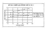
도 3 및 도 4는 본 발명의 실시예의 LED에 대한, 순방향 전압과 전류, PWM 듀티 사이클과 전력의 관계를 각각 나타낸 그래프.3 and 4 are graphs showing the relationship between forward voltage and current, PWM duty cycle and power, respectively, for the LED of the embodiment of the present invention.
(산소 포화도 측정기의 전단)(Shear of Oxygen Saturation Meter)
도 1은 본 발명에 따른 산소 농도 측정 시스템의 일 실시예를 나타낸다. 센서(10)는 적색광 및 적외선 LED들과 광검출기를 포함한다. 이들은 케이블(12)에 의해 보드(14)에 연결된다. LED 구동 전류는 LED 구동 회로(16)에 의해 제공된다. 센서로부터 수신된 광전류는 I-V 인터페이스(18)에 제공된다. 적외선 및 적색광 전압은, 이후 본 발명에 따른 시그마-델타 인터페이스(20)에 제공된다. 시그마-델타 인터페이스(20)의 출력은, 10 비트 아날로그/디지털 컨버터를 포함하는 마이크로컨트롤러(22)에 제공된다. 마이크로컨트롤러(22)는 프로그램을 위한 플래시 메모리 및 데이터를 위한 SRAM 메모리를 포함한다. 산소 포화도 측정기는 플래시 메모리(26)에 연결된 마이크로프로세서(24)를 포함한다. 또한, 클록(28)이 이용되며, 센서(10)에서의 디지털 캘리브레이션에 대한 인터페이스(30)가 제공된다. 개별 호스 트(32)는, 아날로그 디스플레이를 제공하기 위한 라인(34) 상의 아날로그 신호를 수신할 뿐만 아니라, 처리된 정보도 수신한다.1 shows an embodiment of an oxygen concentration measuring system according to the present invention.
(LED 구동 회로)(LED driving circuit)
도 2는 본 발명의 일 실시예에 따른 LED 구동 회로의 회로도를 나타내고 있으며, 이 회로는 도 1에서 LED 구동 인터페이스(16)의 일부를 형성한다. 전압 조정기(36)는 산소 포화도 측정기의 모든 회로 소자들에 대해, 전압 공급기와는 별개로 전압을 공급한다. 출력은 라인(38)에 4.5 볼트 신호로서 제공되며, 이 레벨은 저항(R89) 및 저항(R90)으로 이루어지는 피드백 저항 분배기에 의해 조정된다. 라인(38)의 전압은, FET 트랜지스터(Q11)로부터 인덕터(L6)로 제공된다. 인덕터(L6)를 지나는 전류는 스위치(40)에 의해 커패시터(C65) 및 커패시터(C66) 중의 어느 하나에 제공되고, 이 커패시터들은 적색광 및 적외선 LED들을 위해 각각 전하를 저장한다. 라인(42)의 적색광/적외선 제어 신호는 산소 포화도 측정기 프로세서의 제어에 따라 스위치의 상태를 결정한다. 라인(44)의 제어 신호인 LED PWM 게이트는 트랜지스터 스위치(Q11)의 스위칭을 제어한다.2 shows a circuit diagram of an LED drive circuit according to an embodiment of the present invention, which forms part of the
커패시터(C65) 및 커패시터(C66)가 충전되면, 라인(44)의 제어 신호는 스위치(Q11)를 턴오프하고, 전류는 커패시터(Q65) 또는 커패시터(Q66)로부터, 스위치(40) 및 인턱터(L6)를 통해 트랜지스터(Q5) 및 트랜지스터(Q6)의 경로를 각각 경유하여 적색광 양극 라인(46) 또는 적외선 양극 라인(48) 중의 하나에 제공된다. 신호 "적색광 게이트"는 트랜지스터(Q5)를 턴온하고, 반대의 경우인 "/적색광 게이 트"는 트랜지스터(Q7)를 턴오프한다. 이는, 적외선 양극을 통해 트랜지스터(Q8)로 그리고 저항(R10)을 통해 접지로 되돌아오는 전류를, 적색광 양극 라인(46)을 통해 백투백(back to back) LED(50)에 공급한다. 트랜지스터(Q8)는 신호 "/적외선 게이트"에 의해 턴온되고, 이 신호의 반대의 경우인 "적외선 게이트"는 트랜지스터(Q6)를 턴오프한다. "적외선 게이트"와 "적색광 게이트" 및 이들의 반대되는 신호들은, 적외선 양극이 구동되어야 할 때 반전되거나 상태가 변경되며, 이에 의해 전류는 트랜지스터(Q6)를 통해 적외선 양극(48)에 제공되고, 적색광 양극(46)을 통해 되돌아오거나 트랜지스터(Q7)를 통해 저항(R10) 및 접지로 되돌아온다. "LED 전류 감지" 신호는, 본 발명과는 무관한 캘리브레이션 목적을 위해 독출된다.When capacitor C65 and capacitor C66 are charged, control signal of line 44 turns off switch Q11, and current flows from capacitor Q65 or capacitor Q66 to switch 40 and inductor ( Via L6 is provided to either the red
커패시터(C65) 또는 커패시터(C66)로부터의 전류가 인덕터(L6)를 통해 LED로 제공되고, 이 전류가 원하는 시간에 오프로 스위칭되면, 트랜지스터(Q11)는 턴온되고, 이에 의해, 변화되는 동안의 잔여 전류는 커패시터(C64)에 덤프될 수 있다. 이는, FET 트랜지스터의 스위칭은 즉각적으로 이루어지지 않는다는 사실을 암시한다. 결과적으로, 커패시터(C64)는, 재충전될 때, 트랜지스터(Q11) 및 인덕터(L6)를 통하여 커패시터에 자신의 전류를 덤프한다.If a current from capacitor C65 or capacitor C66 is provided to the LED through inductor L6 and this current is switched off at the desired time, transistor Q11 is turned on, thereby changing the Residual current may be dumped into capacitor C64. This suggests that switching of FET transistors is not instantaneous. As a result, the capacitor C64 dumps its current to the capacitor through the transistor Q11 and the inductor L6 when recharged.
저항(R38) 및 커패시터(C67)는 신호의 스파이크를 방지하기 위해 인덕터(L6)에 병렬로 연결되어 있으며, 따라서 완만한 변화를 제공하게 된다. 인덕터(L6)에는 신호들을 샘플링하기 위한 샘플링 회로가 접속되어 있으며, 이 샘플링 회로는 신호들을 샘플링하고 이 신호를 증폭기(56)를 통해 프로세서에 의해 읽혀지는 라인(58)의 "LED 전류" 신호로서 제공하기 위해, 라인(54)의 LED 샘플 홀드 신호에 의해 제 어되는 스위치(52)를 포함한다. 집적 커패시터(C68)는 증폭기(56)에 피드백을 제공한다. 스위치(60)는, 샘플들 사이에서의 커패시터를 방전시키도록 스위치를 조작하기 위하여 "LED 샘플 소거" 신호에 따라 동작한다.Resistor R38 and capacitor C67 are connected in parallel to inductor L6 to prevent signal spikes, thus providing a gentle change. Inductor L6 is connected with a sampling circuit for sampling the signals, which sample the signals and convert this signal as the " LED current " signal of
동작중인 증폭기(56)는 4.5 볼트와 접지 사이에서 동작한다. 따라서, 접지보다 조금 높은 0.2 볼트의 기준 전압이 핀(3)의 기준 전압으로서 제공된다.The
샘플 홀드 회로는, 전류를 결정하기 위해, 커패시터(C69)와 인덕터(L6) 사이인 노드(T18)의 전압을 측정한다. 커패시터(C69)는, 커패시터(C65) 및 커패시터(C66)의 값의 1/1000이다. 따라서, 전류는, 이에 비례하여 커패시터(C69)를 통하여 제공되며, 라인(58)의 증폭기(56)의 출력에서 측정될 수 있는 전압을 제공하기 위해, 스위치(52)를 통해 집적 커패시터(C68)에 제공된다. 라인(58)에서 프로세서에 의해 측정된 전압은 피드백으로서 이용되며, 프로세서는 커패시터(C65) 및 커패시터(C66)로 전달되는 에너지의 양을 선택적으로 변화시키기 위하여 트랜지스터(Q11)에 전달되는 펄스의 폭을 변화시키고, 이 전압은 결국 LED(50)들로 방전된다. PI 루프를 포함하는 프로세서는 트랜지스터(Q11)를 제어하는 PWM 신호를 제어한다. 이는 LED의 밝기를 세밀하게 제어할 수 있게 하며, 필요하다면, 소정의 한계를 넘지 않는 한도 내에서 최대로 동작하도록 할 수도 있다.The sample hold circuit measures the voltage at node T18, which is between capacitor C69 and inductor L6, to determine the current. The capacitor C69 is 1/1000 of the values of the capacitor C65 and the capacitor C66. Thus, current is provided in proportion to capacitor C69 and through
도면의 좌측 하단부에는, 특정의 경우에 전압 조정기(36)를 턴오프하기 위해 마이크로프로세서에 의해 이용되는 "4.5V LED 디스에이블" 신호가 나타내져 있다. 예를 들어, LED 라인에 문제가 발생한 경우, 새로 연결된 센서에서의 단락이 발견되면 전압 조정기를 턴오프할 것이다.In the lower left of the figure, there is shown a " 4.5 V LED disable " signal that is used by the microprocessor to turn off the
(LED 전압 결정)(LED voltage determination)
도 3 및 4는 본 발명의 특징들을 나타낸 도면이다. 도 3은 LED 순방향 전압과 LED 전류에 대한 그래프이다. 이 그래프는, 부하의 종류에 따라 각각 서로 다른 경사를 갖는 세개의 선분들을 포함한다: 적외선 LED, 적색광 LED 및 다이오드와 저항이 직렬로 연결된 테스터(SRC). 도시된 바와 같이, 도 3에 도시된 바와 같은 곡선과 같이 전류를 단독으로 측정하는 것은, 부하의 종류를 알고 있는 경우가 아니라면 LED 순방향 전압을 나타낼 수 없다.3 and 4 illustrate features of the present invention. 3 is a graph of LED forward voltage and LED current. The graph includes three line segments, each with different slopes, depending on the type of load: an infrared LED, a red LED, and a diode and a tester (SRC) in series with a resistor. As shown, measuring current alone, such as a curve as shown in FIG. 3, cannot represent the LED forward voltage unless the type of load is known.
도 4는, LED를 구동하기 위한 펄스폭 변조된 구동 신호인 LED PWM 듀티 사이클을 나타낸 도면이다. 이는 세로축으로 표시되며, 가로축에는 전력(LED 전압과 LED 전류의 곱)이 표시된다. 도시된 바와 같이, 네가지 종류의 LED 또는 SRC 디바이스들이 표시되어 있으며, 이 선분들은 거의 동일한 경사를 가지며 거의 동일하다. 이러한 특성에 의해, PWM 듀티 사이클과 전류를 알 수 있다면, 전압을 결정할 수 있게 된다. 전류는 도 2에서의 라인(58)의 프로세서로 제공되는 LED 전류 신호로부터 알 수 있다. 또한, 프로세서에서 PWM 신호가 생성되기 때문에, 프로세서는, LED의 종류를 알 필요가 없이, 특정 LED의 LED 전압을 계산하기 위해 필요한 두가지 정보를 얻을 수 있게 된다. 도 4의 정보를 이용함으로써, 듀티 사이클은 LED에서 소모하는 전력에 대해 정비례하는 것을 알 수 있고, 따라서, 순방향 전압을 알 수 있게 된다.4 is a diagram illustrating an LED PWM duty cycle, which is a pulse width modulated drive signal for driving an LED. This is indicated by the vertical axis, and the horizontal axis shows the power (the product of the LED voltage and the LED current). As shown, four types of LED or SRC devices are indicated, and these segments have almost the same slope and are nearly identical. This characteristic allows the voltage to be determined if the PWM duty cycle and current are known. The current can be seen from the LED current signal provided to the processor of
일 실시예에서, PWM 신호는 PI 루프를 이용하여 생성된다. 이 루프는 이하의 일반식을 갖는다:In one embodiment, the PWM signal is generated using a PI loop. This loop has the following general formula:
y = Ae(t) + B∫e(t)dty = Ae (t) + B∫e (t) dt
여기에서, A, B는 상수Where A and B are constants
e = 에러 신호, 원하는 전류와 실제 전류 사이의 차이e = error signal, the difference between the desired current and the actual current
y = PWM 신호이다.y = PWM signal.
일 실시예에서, 프로세서에 의해 생성된 PWM 듀티 사이클은, 도 4의 그래프의 데이터를 저장하고 있는 룩업 테이블에 제공된다. 룩업 테이블은 출력에서 소모되는 전력을 산출한다. 이 값은 이후, 라인(58)에서 제공되는 LED 전류에 의해 나눗셈된다. 이 나눗셈의 결과는 LED의 순방향 전압이 된다.In one embodiment, the PWM duty cycle generated by the processor is provided to a lookup table that stores the data of the graph of FIG. 4. The lookup table calculates the power consumed at the output. This value is then divided by the LED current provided at
한편, 또다른 실시예에서는, 룩업 테이블이 사용되지 않을 수 있으며, 이때는 듀티 사이클과 전류의 비교가 이루어진다. 듀티 사이클은 전류와 전압과 상수의 곱으로 표현될 수 있기 때문에, (듀티 사이클)/(LED 전류) 비율에 대한 상한 및 하한의 범위에 의해, LED의 단락이나 단선과 같은 상태를 표시하도록 할 수도 있다. 한편, 단락 또는 단선 상태를 표시하기 위한 외부 범위 및 하나의 예시로써 LED의 원하는 동작 범위를 표시하는 내부 범위를 포함하는 다수의 연속된 범위들을 이용할 수도 있다. 예를 들면, 산소 포화도 측정기에 있어서, 맥박 신호가 약한 어떤 환자에 대해서는, LED를 최대 허용 전류에 가까운 상태로 무리하게 구동시킬 필요가 있을 수 있다.On the other hand, in another embodiment, the lookup table may not be used, where a comparison of the duty cycle and current is made. Since the duty cycle can be expressed as the product of current, voltage, and constant, the upper and lower ranges for the (duty cycle) / (LED current) ratio can be used to indicate a state such as an LED short or disconnection. have. On the other hand, a number of consecutive ranges may be used, including an external range for indicating a short or disconnected state and an internal range for indicating a desired operating range of the LED as an example. For example, in an oxygen saturation meter, for some patients with weak pulse signals, it may be necessary to forcibly drive the LED to a state close to the maximum allowable current.
본 발명은, 본 발명의 기술 분야의 당업자에 의해 이해될 수 있는 바와 같 이, 근본적인 특징으로부터 벗어나지 않는 한 다양하게 실시될 수 있다. 예를 들면, 순방향 전압의 결정은, 프로세서에 의한 소프트웨어적으로뿐만 아니라, 하드웨어만으로도 수행될 수 있다. 따라서, 상술한 내용은 단지 본 발명을 설명하고자 하는 것으로서, 어떠한 한정을 위한 것이 아니며, 본 발명의 범위는 이하의 청구항에 의해 정해져야 할 것이다.As will be appreciated by those skilled in the art, the present invention may be embodied in various ways without departing from the essential features. For example, the determination of the forward voltage can be performed not only in software by the processor but also in hardware alone. Accordingly, the foregoing description is merely intended to explain the invention, and is not intended to be limiting, and the scope of the invention should be defined by the following claims.
Claims (10)
Translated fromKoreanApplications Claiming Priority (2)
| Application Number | Priority Date | Filing Date | Title |
|---|---|---|---|
| US10/788,243 | 2004-02-25 | ||
| US10/788,243US7120480B2 (en) | 2004-02-25 | 2004-02-25 | LED forward voltage estimation in pulse oximeter |
Publications (1)
| Publication Number | Publication Date |
|---|---|
| KR20060134102Atrue KR20060134102A (en) | 2006-12-27 |
Family
ID=34861966
Family Applications (1)
| Application Number | Title | Priority Date | Filing Date |
|---|---|---|---|
| KR1020067018547AWithdrawnKR20060134102A (en) | 2004-02-25 | 2005-02-25 | Forward Voltage Estimation of Light Emitting Diode in Pulse Oxygen Saturation Meter |
Country Status (9)
| Country | Link |
|---|---|
| US (1) | US7120480B2 (en) |
| EP (1) | EP1722854A1 (en) |
| JP (1) | JP2007523730A (en) |
| KR (1) | KR20060134102A (en) |
| CN (1) | CN1929890A (en) |
| AU (1) | AU2005216973A1 (en) |
| CA (1) | CA2556716A1 (en) |
| MX (1) | MXPA06009752A (en) |
| WO (1) | WO2005082455A1 (en) |
Families Citing this family (22)
| Publication number | Priority date | Publication date | Assignee | Title |
|---|---|---|---|---|
| US7647083B2 (en) | 2005-03-01 | 2010-01-12 | Masimo Laboratories, Inc. | Multiple wavelength sensor equalization |
| US7999484B2 (en) | 2005-12-20 | 2011-08-16 | Koninklijke Philips Electronics N.V. | Method and apparatus for controlling current supplied to electronic devices |
| JP5043111B2 (en)* | 2006-08-17 | 2012-10-10 | コーニンクレッカ フィリップス エレクトロニクス エヌ ヴィ | Method and apparatus for reducing thermal stress in light emitting devices |
| US8265723B1 (en) | 2006-10-12 | 2012-09-11 | Cercacor Laboratories, Inc. | Oximeter probe off indicator defining probe off space |
| US20080221418A1 (en)* | 2007-03-09 | 2008-09-11 | Masimo Corporation | Noninvasive multi-parameter patient monitor |
| US8265724B2 (en) | 2007-03-09 | 2012-09-11 | Nellcor Puritan Bennett Llc | Cancellation of light shunting |
| EP2139383B1 (en) | 2007-03-27 | 2013-02-13 | Masimo Laboratories, Inc. | Multiple wavelength optical sensor |
| US20080262326A1 (en)* | 2007-04-19 | 2008-10-23 | Starr Life Sciences Corp. | Signal Processing Method and Apparatus for Processing a Physiologic Signal such as a Photoplethysmography Signal |
| US8374665B2 (en) | 2007-04-21 | 2013-02-12 | Cercacor Laboratories, Inc. | Tissue profile wellness monitor |
| TWI367050B (en)* | 2007-12-12 | 2012-06-21 | Au Optronics Corp | Color control method for led lighting system |
| US8366613B2 (en) | 2007-12-26 | 2013-02-05 | Covidien Lp | LED drive circuit for pulse oximetry and method for using same |
| EP2262414A1 (en)* | 2008-03-31 | 2010-12-22 | Nellcor Puritan Bennett LLC | Medical monitoring patch device and methods |
| US9404961B2 (en)* | 2008-12-09 | 2016-08-02 | Covidien Lp | System and method of determining light source aging |
| US9066660B2 (en) | 2009-09-29 | 2015-06-30 | Nellcor Puritan Bennett Ireland | Systems and methods for high-pass filtering a photoplethysmograph signal |
| US9839381B1 (en) | 2009-11-24 | 2017-12-12 | Cercacor Laboratories, Inc. | Physiological measurement system with automatic wavelength adjustment |
| WO2011069122A1 (en) | 2009-12-04 | 2011-06-09 | Masimo Corporation | Calibration for multi-stage physiological monitors |
| US20120253151A1 (en)* | 2011-03-30 | 2012-10-04 | Nellcor Puritan Bennett Llc | Multiple Wavelength Pulse Oximetry With Sensor Redundancy |
| US20150196239A1 (en)* | 2014-01-10 | 2015-07-16 | Covidien Lp | Method and apparatus for driving an emitter in a medical sensor |
| US20180353111A1 (en)* | 2017-06-09 | 2018-12-13 | Covidien Lp | Systems and methods for driving optical sensors |
| US10852230B1 (en) | 2020-04-24 | 2020-12-01 | Covidien Lp | Sensor characterization through forward voltage measurements |
| US10849538B1 (en) | 2020-04-24 | 2020-12-01 | Covidien Lp | Sensor verification through forward voltage measurements |
| JP7574033B2 (en)* | 2020-09-30 | 2024-10-28 | 日本光電工業株式会社 | Biological parameter calculation device, computer program, and non-transitory computer-readable medium |
Family Cites Families (18)
| Publication number | Priority date | Publication date | Assignee | Title |
|---|---|---|---|---|
| US4934372A (en)* | 1985-04-01 | 1990-06-19 | Nellcor Incorporated | Method and apparatus for detecting optical pulses |
| US4911167A (en)* | 1985-06-07 | 1990-03-27 | Nellcor Incorporated | Method and apparatus for detecting optical pulses |
| US4802486A (en) | 1985-04-01 | 1989-02-07 | Nellcor Incorporated | Method and apparatus for detecting optical pulses |
| US4928692A (en)* | 1985-04-01 | 1990-05-29 | Goodman David E | Method and apparatus for detecting optical pulses |
| US4802488A (en)* | 1986-11-06 | 1989-02-07 | Sri International | Blood pressure monitoring method and apparatus |
| EP0477417A1 (en)* | 1990-09-28 | 1992-04-01 | Hewlett-Packard GmbH | System for measuring a blood parameter and method therefor |
| US5351685A (en)* | 1991-08-05 | 1994-10-04 | Nellcor Incorporated | Condensed oximeter system with noise reduction software |
| JP3165983B2 (en)* | 1992-06-15 | 2001-05-14 | 日本光電工業株式会社 | Light emitting element driving device for pulse oximeter |
| US5368224A (en)* | 1992-10-23 | 1994-11-29 | Nellcor Incorporated | Method for reducing ambient noise effects in electronic monitoring instruments |
| US5368026A (en)* | 1993-03-26 | 1994-11-29 | Nellcor Incorporated | Oximeter with motion detection for alarm modification |
| US5859658A (en)* | 1995-10-19 | 1999-01-12 | Xerox Corporation | LED printbar aging compensation using I-V slope characteristics |
| US5746697A (en)* | 1996-02-09 | 1998-05-05 | Nellcor Puritan Bennett Incorporated | Medical diagnostic apparatus with sleep mode |
| US5821921A (en)* | 1996-08-09 | 1998-10-13 | Osborn; John J. | Cursor controller having cross-translating platforms with a cantilevered handle |
| US5921921A (en) | 1996-12-18 | 1999-07-13 | Nellcor Puritan-Bennett | Pulse oximeter with sigma-delta converter |
| US6356774B1 (en)* | 1998-09-29 | 2002-03-12 | Mallinckrodt, Inc. | Oximeter sensor with encoded temperature characteristic |
| US6226539B1 (en)* | 1999-05-26 | 2001-05-01 | Mallinckrodt, Inc. | Pulse oximeter having a low power led drive |
| US6560470B1 (en)* | 2000-11-15 | 2003-05-06 | Datex-Ohmeda, Inc. | Electrical lockout photoplethysmographic measurement system |
| US6882874B2 (en) | 2002-02-15 | 2005-04-19 | Datex-Ohmeda, Inc. | Compensation of human variability in pulse oximetry |
- 2004
- 2004-02-25USUS10/788,243patent/US7120480B2/ennot_activeExpired - Lifetime
- 2005
- 2005-02-25KRKR1020067018547Apatent/KR20060134102A/ennot_activeWithdrawn
- 2005-02-25AUAU2005216973Apatent/AU2005216973A1/ennot_activeAbandoned
- 2005-02-25MXMXPA06009752Apatent/MXPA06009752A/ennot_activeApplication Discontinuation
- 2005-02-25CACA002556716Apatent/CA2556716A1/ennot_activeAbandoned
- 2005-02-25JPJP2007501029Apatent/JP2007523730A/enactivePending
- 2005-02-25WOPCT/US2005/006205patent/WO2005082455A1/enactiveApplication Filing
- 2005-02-25EPEP05723884Apatent/EP1722854A1/ennot_activeWithdrawn
- 2005-02-25CNCNA2005800058571Apatent/CN1929890A/enactivePending
Also Published As
| Publication number | Publication date |
|---|---|
| CN1929890A (en) | 2007-03-14 |
| JP2007523730A (en) | 2007-08-23 |
| MXPA06009752A (en) | 2007-03-15 |
| CA2556716A1 (en) | 2005-09-09 |
| EP1722854A1 (en) | 2006-11-22 |
| WO2005082455A1 (en) | 2005-09-09 |
| US7120480B2 (en) | 2006-10-10 |
| US20050187450A1 (en) | 2005-08-25 |
| AU2005216973A1 (en) | 2005-09-09 |
Similar Documents
| Publication | Publication Date | Title |
|---|---|---|
| KR20060134102A (en) | Forward Voltage Estimation of Light Emitting Diode in Pulse Oxygen Saturation Meter | |
| US6668183B2 (en) | Diode detection circuit | |
| JP4578683B2 (en) | Multi-code oximeter calibration element | |
| US11246515B2 (en) | LED control utilizing ambient light or signal quality | |
| US4942877A (en) | Device for measuring oxygen saturation degree in arterial blood | |
| US6863652B2 (en) | Power conserving adaptive control system for generating signal in portable medical devices | |
| US6298252B1 (en) | Oximeter sensor with encoder connected to detector | |
| KR20060134091A (en) | Red Light and Infrared Zero Calibration Control of Oxygen Saturation Meter | |
| US20150196239A1 (en) | Method and apparatus for driving an emitter in a medical sensor | |
| US20040030231A1 (en) | Oximeter with nulled op-amp current feedback | |
| KR20070026417A (en) | Light Emitting Diode Driven by Single Inductor in Switch-Mode Oxygen Saturation Meter | |
| US20070112259A1 (en) | Vital information measuring device | |
| US7841985B2 (en) | Sensor identification method and system | |
| US20070123760A1 (en) | Signal transmitter and control circuit for a physiological variable | |
| US11849923B2 (en) | Wearable blood gas monitor | |
| JP5958222B2 (en) | Biological information measuring apparatus and parameter setting method in the apparatus | |
| US20240285197A1 (en) | Systems and methods for measuring oxygen in a patient's bloodstream | |
| JP2004290412A (en) | Blood analyzer | |
| US20090270699A1 (en) | Device for Determining Physiological Variables | |
| Li | Pulse oximetry | |
| US20250072876A1 (en) | Miniaturized bimodal oxygen monitoring wearable device | |
| US20180078140A1 (en) | Biological signal detection device | |
| KR20170043360A (en) | Pulse measurement apparatus and method for controlling operation thereof | |
| WO2025106943A1 (en) | Miniaturized bimodal oxygen monitoring wearable device | |
| KR20070020427A (en) | Device for detecting heart rate and reducing power consumption of the sensor |
Legal Events
| Date | Code | Title | Description |
|---|---|---|---|
| PA0105 | International application | Patent event date:20060911 Patent event code:PA01051R01D Comment text:International Patent Application | |
| PG1501 | Laying open of application | ||
| PC1203 | Withdrawal of no request for examination | ||
| WITN | Application deemed withdrawn, e.g. because no request for examination was filed or no examination fee was paid |