KR20060132588A - Tools and tool kits for performing minimal intervention of the spine - Google Patents
Tools and tool kits for performing minimal intervention of the spineDownload PDFInfo
- Publication number
- KR20060132588A KR20060132588AKR1020067010056AKR20067010056AKR20060132588AKR 20060132588 AKR20060132588 AKR 20060132588AKR 1020067010056 AKR1020067010056 AKR 1020067010056AKR 20067010056 AKR20067010056 AKR 20067010056AKR 20060132588 AKR20060132588 AKR 20060132588A
- Authority
- KR
- South Korea
- Prior art keywords
- guide pin
- guide
- cutter
- base
- handle
- Prior art date
- Legal status (The legal status is an assumption and is not a legal conclusion. Google has not performed a legal analysis and makes no representation as to the accuracy of the status listed.)
- Ceased
Links
- 238000000034methodMethods0.000claimsabstractdescription233
- 210000000988bone and boneAnatomy0.000claimsabstractdescription88
- 238000011282treatmentMethods0.000claimsabstractdescription61
- 230000033001locomotionEffects0.000claimsabstractdescription30
- 238000010079rubber tappingMethods0.000claimsabstractdescription4
- 210000001519tissueAnatomy0.000claimsdescription100
- 238000000605extractionMethods0.000claimsdescription89
- 238000003780insertionMethods0.000claimsdescription81
- 230000037431insertionEffects0.000claimsdescription81
- 239000000463materialSubstances0.000claimsdescription78
- 239000000523sampleSubstances0.000claimsdescription61
- 238000005520cutting processMethods0.000claimsdescription50
- 229910001220stainless steelInorganic materials0.000claimsdescription35
- 239000010935stainless steelSubstances0.000claimsdescription34
- 238000000926separation methodMethods0.000claimsdescription30
- 238000013459approachMethods0.000claimsdescription21
- 238000002360preparation methodMethods0.000claimsdescription20
- 238000012546transferMethods0.000claimsdescription20
- 230000008878couplingEffects0.000claimsdescription18
- 238000010168coupling processMethods0.000claimsdescription18
- 238000005859coupling reactionMethods0.000claimsdescription18
- 230000000295complement effectEffects0.000claimsdescription16
- 210000004872soft tissueAnatomy0.000claimsdescription16
- 229910001000nickel titaniumInorganic materials0.000claimsdescription13
- 230000002829reductive effectEffects0.000claimsdescription10
- 239000010936titaniumSubstances0.000claimsdescription8
- RTAQQCXQSZGOHL-UHFFFAOYSA-NTitaniumChemical compound[Ti]RTAQQCXQSZGOHL-UHFFFAOYSA-N0.000claimsdescription7
- 229910052751metalInorganic materials0.000claimsdescription7
- 239000002184metalSubstances0.000claimsdescription7
- 230000008468bone growthEffects0.000claimsdescription6
- 229910052719titaniumInorganic materials0.000claimsdescription6
- 230000004323axial lengthEffects0.000claimsdescription3
- 238000004321preservationMethods0.000claimsdescription3
- 239000003550markerSubstances0.000claimsdescription2
- 238000010298pulverizing processMethods0.000claims2
- 239000002639bone cementSubstances0.000claims1
- 239000000126substanceSubstances0.000claims1
- 210000004705lumbosacral regionAnatomy0.000abstractdescription7
- 210000000954sacrococcygeal regionAnatomy0.000abstractdescription2
- 239000007943implantSubstances0.000description29
- 210000000278spinal cordAnatomy0.000description19
- 239000007787solidSubstances0.000description12
- 208000002193PainDiseases0.000description11
- 210000003811fingerAnatomy0.000description11
- 230000006870functionEffects0.000description11
- 230000007246mechanismEffects0.000description11
- 230000006911nucleationEffects0.000description11
- 238000010899nucleationMethods0.000description11
- 230000008901benefitEffects0.000description10
- 239000011824nuclear materialSubstances0.000description10
- 230000036407painEffects0.000description10
- 206010061246Intervertebral disc degenerationDiseases0.000description9
- 210000000845cartilageAnatomy0.000description9
- 229920001577copolymerPolymers0.000description9
- 230000004927fusionEffects0.000description9
- 238000001356surgical procedureMethods0.000description9
- 208000008035Back PainDiseases0.000description8
- 239000000853adhesiveSubstances0.000description8
- 230000001070adhesive effectEffects0.000description8
- 230000000740bleeding effectEffects0.000description8
- 230000006378damageEffects0.000description8
- 229920000642polymerPolymers0.000description8
- -1polyethylenesPolymers0.000description7
- 238000011084recoveryMethods0.000description7
- 208000027418Wounds and injuryDiseases0.000description6
- 239000000956alloySubstances0.000description6
- 238000011882arthroplastyMethods0.000description6
- 238000003384imaging methodMethods0.000description6
- 238000002513implantationMethods0.000description6
- 230000008569processEffects0.000description6
- 229910045601alloyInorganic materials0.000description5
- 208000037873arthrodesisDiseases0.000description5
- 239000002131composite materialSubstances0.000description5
- 230000006835compressionEffects0.000description5
- 238000007906compressionMethods0.000description5
- 238000002347injectionMethods0.000description5
- 239000007924injectionSubstances0.000description5
- 208000014674injuryDiseases0.000description5
- 239000010410layerSubstances0.000description5
- 210000003041ligamentAnatomy0.000description5
- 210000005036nerveAnatomy0.000description5
- HLXZNVUGXRDIFK-UHFFFAOYSA-Nnickel titaniumChemical compound[Ti].[Ti].[Ti].[Ti].[Ti].[Ti].[Ti].[Ti].[Ti].[Ti].[Ti].[Ni].[Ni].[Ni].[Ni].[Ni].[Ni].[Ni].[Ni].[Ni].[Ni].[Ni].[Ni].[Ni].[Ni]HLXZNVUGXRDIFK-UHFFFAOYSA-N0.000description5
- 230000037361pathwayEffects0.000description5
- 238000002560therapeutic procedureMethods0.000description5
- 230000000472traumatic effectEffects0.000description5
- 208000003618Intervertebral Disc DisplacementDiseases0.000description4
- 239000002033PVDF binderSubstances0.000description4
- 229910052782aluminiumInorganic materials0.000description4
- XAGFODPZIPBFFR-UHFFFAOYSA-NaluminiumChemical compound[Al]XAGFODPZIPBFFR-UHFFFAOYSA-N0.000description4
- 230000003416augmentationEffects0.000description4
- 239000003814drugSubstances0.000description4
- 201000008482osteoarthritisDiseases0.000description4
- 238000012856packingMethods0.000description4
- 229920002981polyvinylidene fluoridePolymers0.000description4
- 230000001225therapeutic effectEffects0.000description4
- 230000008733traumaEffects0.000description4
- 208000008930Low Back PainDiseases0.000description3
- 239000004743PolypropyleneSubstances0.000description3
- DHKHKXVYLBGOIT-UHFFFAOYSA-Nacetaldehyde Diethyl AcetalNatural productsCCOC(C)OCCDHKHKXVYLBGOIT-UHFFFAOYSA-N0.000description3
- 230000009471actionEffects0.000description3
- 230000000694effectsEffects0.000description3
- 230000036541healthEffects0.000description3
- 239000000017hydrogelSubstances0.000description3
- 230000004054inflammatory processEffects0.000description3
- 229920001778nylonPolymers0.000description3
- 230000035790physiological processes and functionsEffects0.000description3
- 229920002492poly(sulfone)Polymers0.000description3
- 229920000515polycarbonatePolymers0.000description3
- 239000004417polycarbonateSubstances0.000description3
- 229920001155polypropylenePolymers0.000description3
- 239000004800polyvinyl chlorideSubstances0.000description3
- 229910001285shape-memory alloyInorganic materials0.000description3
- 208000005198spinal stenosisDiseases0.000description3
- 210000000115thoracic cavityAnatomy0.000description3
- 210000002517zygapophyseal jointAnatomy0.000description3
- 241000197236Chrysanthemoides moniliferaSpecies0.000description2
- 229920004943Delrin®Polymers0.000description2
- 206010016654FibrosisDiseases0.000description2
- 208000007101Muscle CrampDiseases0.000description2
- 201000002481MyositisDiseases0.000description2
- 229910000990Ni alloyInorganic materials0.000description2
- 239000004677NylonSubstances0.000description2
- 239000004698PolyethyleneSubstances0.000description2
- 208000005392SpasmDiseases0.000description2
- HZEWFHLRYVTOIW-UHFFFAOYSA-N[Ti].[Ni]Chemical compound[Ti].[Ni]HZEWFHLRYVTOIW-UHFFFAOYSA-N0.000description2
- NIXOWILDQLNWCW-UHFFFAOYSA-Nacrylic acid groupChemical groupC(C=C)(=O)ONIXOWILDQLNWCW-UHFFFAOYSA-N0.000description2
- 229920000122acrylonitrile butadiene styrenePolymers0.000description2
- 239000004676acrylonitrile butadiene styreneSubstances0.000description2
- 238000004026adhesive bondingMethods0.000description2
- 210000003484anatomyAnatomy0.000description2
- 238000004873anchoringMethods0.000description2
- TZCXTZWJZNENPQ-UHFFFAOYSA-Lbarium sulfateChemical compound[Ba+2].[O-]S([O-])(=O)=OTZCXTZWJZNENPQ-UHFFFAOYSA-L0.000description2
- 230000014461bone developmentEffects0.000description2
- 238000010276constructionMethods0.000description2
- 238000007796conventional methodMethods0.000description2
- 230000001054cortical effectEffects0.000description2
- 208000018180degenerative disc diseaseDiseases0.000description2
- 230000003412degenerative effectEffects0.000description2
- 238000013461designMethods0.000description2
- 201000010099diseaseDiseases0.000description2
- 208000037265diseases, disorders, signs and symptomsDiseases0.000description2
- 238000005553drillingMethods0.000description2
- 229940079593drugDrugs0.000description2
- 238000005516engineering processMethods0.000description2
- 239000000284extractSubstances0.000description2
- 230000004761fibrosisEffects0.000description2
- 238000011049fillingMethods0.000description2
- 239000012634fragmentSubstances0.000description2
- 230000035876healingEffects0.000description2
- 238000010438heat treatmentMethods0.000description2
- 229920001903high density polyethylenePolymers0.000description2
- 239000004700high-density polyethyleneSubstances0.000description2
- KHYBPSFKEHXSLX-UHFFFAOYSA-NiminotitaniumChemical compound[Ti]=NKHYBPSFKEHXSLX-UHFFFAOYSA-N0.000description2
- 238000001746injection mouldingMethods0.000description2
- 208000021600intervertebral disc degenerative diseaseDiseases0.000description2
- 238000002684laminectomyMethods0.000description2
- 229920001684low density polyethylenePolymers0.000description2
- 239000004702low-density polyethyleneSubstances0.000description2
- 238000003032molecular dockingMethods0.000description2
- 210000000944nerve tissueAnatomy0.000description2
- 230000002188osteogenic effectEffects0.000description2
- 230000036961partial effectEffects0.000description2
- 230000000149penetrating effectEffects0.000description2
- 229920000573polyethylenePolymers0.000description2
- 239000002861polymer materialSubstances0.000description2
- 230000000750progressive effectEffects0.000description2
- 230000001681protective effectEffects0.000description2
- 230000008439repair processEffects0.000description2
- 230000004044responseEffects0.000description2
- 206010039073rheumatoid arthritisDiseases0.000description2
- 230000035939shockEffects0.000description2
- 239000004094surface-active agentSubstances0.000description2
- 230000000007visual effectEffects0.000description2
- XLYOFNOQVPJJNP-UHFFFAOYSA-NwaterSubstancesOXLYOFNOQVPJJNP-UHFFFAOYSA-N0.000description2
- 206010002091AnaesthesiaDiseases0.000description1
- 208000018084Bone neoplasmDiseases0.000description1
- XWGXFOVSOYMSGT-UHFFFAOYSA-NCC(C)NC1CC1Chemical compoundCC(C)NC1CC1XWGXFOVSOYMSGT-UHFFFAOYSA-N0.000description1
- 241001631457CannulaSpecies0.000description1
- 229910000531Co alloyInorganic materials0.000description1
- 229920000742CottonPolymers0.000description1
- 206010061818Disease progressionDiseases0.000description1
- 102000004190EnzymesHuman genes0.000description1
- 108090000790EnzymesProteins0.000description1
- 102000009123FibrinHuman genes0.000description1
- 108010073385FibrinProteins0.000description1
- BWGVNKXGVNDBDI-UHFFFAOYSA-NFibrin monomerChemical compoundCNC(=O)CNC(=O)CNBWGVNKXGVNDBDI-UHFFFAOYSA-N0.000description1
- 206010016818FluorosisDiseases0.000description1
- 241001149900Fusconaia subrotundaSpecies0.000description1
- 206010061218InflammationDiseases0.000description1
- 206010027476MetastasesDiseases0.000description1
- 206010028980NeoplasmDiseases0.000description1
- 208000010191Osteitis DeformansDiseases0.000description1
- 208000027067Paget disease of boneDiseases0.000description1
- 239000004696Poly ether ether ketoneSubstances0.000description1
- 206010037660PyrexiaDiseases0.000description1
- 206010037779RadiculopathyDiseases0.000description1
- 206010041591Spinal osteoarthritisDiseases0.000description1
- QAOWNCQODCNURD-UHFFFAOYSA-LSulfateChemical compound[O-]S([O-])(=O)=OQAOWNCQODCNURD-UHFFFAOYSA-L0.000description1
- 229910001069Ti alloyInorganic materials0.000description1
- 238000002441X-ray diffractionMethods0.000description1
- 239000006096absorbing agentSubstances0.000description1
- 238000009825accumulationMethods0.000description1
- 125000002777acetyl groupChemical class[H]C([H])([H])C(*)=O0.000description1
- 229920006397acrylic thermoplasticPolymers0.000description1
- 238000005275alloyingMethods0.000description1
- 230000037005anaesthesiaEffects0.000description1
- 210000001367arteryAnatomy0.000description1
- 206010003246arthritisDiseases0.000description1
- 230000000712assemblyEffects0.000description1
- 238000000429assemblyMethods0.000description1
- 230000000386athletic effectEffects0.000description1
- 230000003190augmentative effectEffects0.000description1
- JUPQTSLXMOCDHR-UHFFFAOYSA-Nbenzene-1,4-diol;bis(4-fluorophenyl)methanoneChemical compoundOC1=CC=C(O)C=C1.C1=CC(F)=CC=C1C(=O)C1=CC=C(F)C=C1JUPQTSLXMOCDHR-UHFFFAOYSA-N0.000description1
- 230000005540biological transmissionEffects0.000description1
- 210000004204blood vesselAnatomy0.000description1
- 230000036760body temperatureEffects0.000description1
- 208000016738bone Paget diseaseDiseases0.000description1
- 210000004556brainAnatomy0.000description1
- 230000008859changeEffects0.000description1
- 238000004891communicationMethods0.000description1
- 238000002788crimpingMethods0.000description1
- 230000018044dehydrationEffects0.000description1
- 238000006297dehydration reactionMethods0.000description1
- 208000004042dental fluorosisDiseases0.000description1
- 230000006866deteriorationEffects0.000description1
- 238000011161developmentMethods0.000description1
- 230000018109developmental processEffects0.000description1
- 238000003745diagnosisMethods0.000description1
- 238000010586diagramMethods0.000description1
- 230000000916dilatatory effectEffects0.000description1
- 230000010339dilationEffects0.000description1
- 238000011038discontinuous diafiltration by volume reductionMethods0.000description1
- 230000005750disease progressionEffects0.000description1
- 238000002224dissectionMethods0.000description1
- 238000009826distributionMethods0.000description1
- 230000009977dual effectEffects0.000description1
- 238000001839endoscopyMethods0.000description1
- 229950003499fibrinDrugs0.000description1
- 238000007667floatingMethods0.000description1
- 238000002594fluoroscopyMethods0.000description1
- 238000013467fragmentationMethods0.000description1
- 238000006062fragmentation reactionMethods0.000description1
- 230000006872improvementEffects0.000description1
- 238000011065in-situ storageMethods0.000description1
- 230000006698inductionEffects0.000description1
- 239000003999initiatorSubstances0.000description1
- 230000003993interactionEffects0.000description1
- 230000002452interceptive effectEffects0.000description1
- 230000009545invasionEffects0.000description1
- 238000005304joiningMethods0.000description1
- 239000007788liquidSubstances0.000description1
- 230000007774longtermEffects0.000description1
- 210000005230lumbar spinal cordAnatomy0.000description1
- 238000004519manufacturing processMethods0.000description1
- 230000005226mechanical processes and functionsEffects0.000description1
- 238000002483medicationMethods0.000description1
- 229910001092metal group alloyInorganic materials0.000description1
- 230000009401metastasisEffects0.000description1
- 230000005012migrationEffects0.000description1
- 238000013508migrationMethods0.000description1
- 238000000465mouldingMethods0.000description1
- 230000007383nerve stimulationEffects0.000description1
- 210000000653nervous systemAnatomy0.000description1
- PXHVJJICTQNCMI-UHFFFAOYSA-NnickelSubstances[Ni]PXHVJJICTQNCMI-UHFFFAOYSA-N0.000description1
- 238000002355open surgical procedureMethods0.000description1
- 210000000056organAnatomy0.000description1
- 230000000399orthopedic effectEffects0.000description1
- 238000004806packaging method and processMethods0.000description1
- 230000002093peripheral effectEffects0.000description1
- 238000005498polishingMethods0.000description1
- 229920003229poly(methyl methacrylate)Polymers0.000description1
- 229920002530polyetherether ketonePolymers0.000description1
- 239000004810polytetrafluoroethyleneSubstances0.000description1
- 229920001343polytetrafluoroethylenePolymers0.000description1
- 229920000915polyvinyl chloridePolymers0.000description1
- 230000002980postoperative effectEffects0.000description1
- 238000004382pottingMethods0.000description1
- 239000000843powderSubstances0.000description1
- 230000001737promoting effectEffects0.000description1
- 230000009467reductionEffects0.000description1
- 238000002271resectionMethods0.000description1
- 238000005096rolling processMethods0.000description1
- 238000007790scrapingMethods0.000description1
- 239000003566sealing materialSubstances0.000description1
- 230000011218segmentationEffects0.000description1
- 208000005801spondylosisDiseases0.000description1
- 230000006641stabilisationEffects0.000description1
- 238000011105stabilizationMethods0.000description1
- 230000000087stabilizing effectEffects0.000description1
- 239000002344surface layerSubstances0.000description1
- 230000008961swellingEffects0.000description1
- ISXSCDLOGDJUNJ-UHFFFAOYSA-Ntert-butyl prop-2-enoateChemical compoundCC(C)(C)OC(=O)C=CISXSCDLOGDJUNJ-UHFFFAOYSA-N0.000description1
- 238000012360testing methodMethods0.000description1
- 229920001169thermoplasticPolymers0.000description1
- 239000004416thermosoftening plasticSubstances0.000description1
- 210000003813thumbAnatomy0.000description1
- 230000000451tissue damageEffects0.000description1
- 231100000827tissue damageToxicity0.000description1
- 238000003325tomographyMethods0.000description1
- 230000007704transitionEffects0.000description1
- 230000007306turnoverEffects0.000description1
- 230000002792vascularEffects0.000description1
- 210000003462veinAnatomy0.000description1
- 239000002435venomSubstances0.000description1
- 210000001048venomAnatomy0.000description1
- 231100000611venomToxicity0.000description1
- 238000012800visualizationMethods0.000description1
- 230000003313weakening effectEffects0.000description1
- 238000003466weldingMethods0.000description1
- 238000004804windingMethods0.000description1
Images


Classifications
- A—HUMAN NECESSITIES
- A61—MEDICAL OR VETERINARY SCIENCE; HYGIENE
- A61B—DIAGNOSIS; SURGERY; IDENTIFICATION
- A61B17/00—Surgical instruments, devices or methods
- A61B17/56—Surgical instruments or methods for treatment of bones or joints; Devices specially adapted therefor
- A61B17/58—Surgical instruments or methods for treatment of bones or joints; Devices specially adapted therefor for osteosynthesis, e.g. bone plates, screws or setting implements
- A61B17/68—Internal fixation devices, including fasteners and spinal fixators, even if a part thereof projects from the skin
- A61B17/70—Spinal positioners or stabilisers, e.g. stabilisers comprising fluid filler in an implant
- A61B17/7074—Tools specially adapted for spinal fixation operations other than for bone removal or filler handling
- A—HUMAN NECESSITIES
- A61—MEDICAL OR VETERINARY SCIENCE; HYGIENE
- A61B—DIAGNOSIS; SURGERY; IDENTIFICATION
- A61B17/00—Surgical instruments, devices or methods
- A61B17/02—Surgical instruments, devices or methods for holding wounds open, e.g. retractors; Tractors
- A61B17/025—Joint distractors
- A—HUMAN NECESSITIES
- A61—MEDICAL OR VETERINARY SCIENCE; HYGIENE
- A61B—DIAGNOSIS; SURGERY; IDENTIFICATION
- A61B17/00—Surgical instruments, devices or methods
- A61B17/56—Surgical instruments or methods for treatment of bones or joints; Devices specially adapted therefor
- A61B17/58—Surgical instruments or methods for treatment of bones or joints; Devices specially adapted therefor for osteosynthesis, e.g. bone plates, screws or setting implements
- A61B17/88—Osteosynthesis instruments; Methods or means for implanting or extracting internal or external fixation devices
- A—HUMAN NECESSITIES
- A61—MEDICAL OR VETERINARY SCIENCE; HYGIENE
- A61B—DIAGNOSIS; SURGERY; IDENTIFICATION
- A61B17/00—Surgical instruments, devices or methods
- A61B17/16—Instruments for performing osteoclasis; Drills or chisels for bones; Trepans
- A61B17/1604—Chisels; Rongeurs; Punches; Stamps
- A—HUMAN NECESSITIES
- A61—MEDICAL OR VETERINARY SCIENCE; HYGIENE
- A61B—DIAGNOSIS; SURGERY; IDENTIFICATION
- A61B17/00—Surgical instruments, devices or methods
- A61B17/16—Instruments for performing osteoclasis; Drills or chisels for bones; Trepans
- A61B17/1662—Instruments for performing osteoclasis; Drills or chisels for bones; Trepans for particular parts of the body
- A61B17/1671—Instruments for performing osteoclasis; Drills or chisels for bones; Trepans for particular parts of the body for the spine
- A—HUMAN NECESSITIES
- A61—MEDICAL OR VETERINARY SCIENCE; HYGIENE
- A61B—DIAGNOSIS; SURGERY; IDENTIFICATION
- A61B17/00—Surgical instruments, devices or methods
- A61B17/16—Instruments for performing osteoclasis; Drills or chisels for bones; Trepans
- A61B17/1697—Instruments for performing osteoclasis; Drills or chisels for bones; Trepans specially adapted for wire insertion
- A—HUMAN NECESSITIES
- A61—MEDICAL OR VETERINARY SCIENCE; HYGIENE
- A61B—DIAGNOSIS; SURGERY; IDENTIFICATION
- A61B17/00—Surgical instruments, devices or methods
- A61B17/16—Instruments for performing osteoclasis; Drills or chisels for bones; Trepans
- A61B17/17—Guides or aligning means for drills, mills, pins or wires
- A61B17/1739—Guides or aligning means for drills, mills, pins or wires specially adapted for particular parts of the body
- A61B17/1757—Guides or aligning means for drills, mills, pins or wires specially adapted for particular parts of the body for the spine
- A—HUMAN NECESSITIES
- A61—MEDICAL OR VETERINARY SCIENCE; HYGIENE
- A61B—DIAGNOSIS; SURGERY; IDENTIFICATION
- A61B17/00—Surgical instruments, devices or methods
- A61B17/22—Implements for squeezing-off ulcers or the like on inner organs of the body; Implements for scraping-out cavities of body organs, e.g. bones; for invasive removal or destruction of calculus using mechanical vibrations; for removing obstructions in blood vessels, not otherwise provided for
- A—HUMAN NECESSITIES
- A61—MEDICAL OR VETERINARY SCIENCE; HYGIENE
- A61B—DIAGNOSIS; SURGERY; IDENTIFICATION
- A61B17/00—Surgical instruments, devices or methods
- A61B17/56—Surgical instruments or methods for treatment of bones or joints; Devices specially adapted therefor
- A61B17/58—Surgical instruments or methods for treatment of bones or joints; Devices specially adapted therefor for osteosynthesis, e.g. bone plates, screws or setting implements
- A61B17/68—Internal fixation devices, including fasteners and spinal fixators, even if a part thereof projects from the skin
- A61B17/84—Fasteners therefor or fasteners being internal fixation devices
- A61B17/86—Pins or screws or threaded wires; nuts therefor
- A61B17/8605—Heads, i.e. proximal ends projecting from bone
- A61B17/861—Heads, i.e. proximal ends projecting from bone specially shaped for gripping driver
- A61B17/8615—Heads, i.e. proximal ends projecting from bone specially shaped for gripping driver at the central region of the screw head
- A—HUMAN NECESSITIES
- A61—MEDICAL OR VETERINARY SCIENCE; HYGIENE
- A61B—DIAGNOSIS; SURGERY; IDENTIFICATION
- A61B17/00—Surgical instruments, devices or methods
- A61B17/56—Surgical instruments or methods for treatment of bones or joints; Devices specially adapted therefor
- A61B17/58—Surgical instruments or methods for treatment of bones or joints; Devices specially adapted therefor for osteosynthesis, e.g. bone plates, screws or setting implements
- A61B17/88—Osteosynthesis instruments; Methods or means for implanting or extracting internal or external fixation devices
- A61B17/8875—Screwdrivers, spanners or wrenches
- A61B17/8877—Screwdrivers, spanners or wrenches characterised by the cross-section of the driver bit
- A61B17/888—Screwdrivers, spanners or wrenches characterised by the cross-section of the driver bit the driver bit acting on the central region of the screw head
- A—HUMAN NECESSITIES
- A61—MEDICAL OR VETERINARY SCIENCE; HYGIENE
- A61B—DIAGNOSIS; SURGERY; IDENTIFICATION
- A61B17/00—Surgical instruments, devices or methods
- A61B17/56—Surgical instruments or methods for treatment of bones or joints; Devices specially adapted therefor
- A61B17/58—Surgical instruments or methods for treatment of bones or joints; Devices specially adapted therefor for osteosynthesis, e.g. bone plates, screws or setting implements
- A61B17/88—Osteosynthesis instruments; Methods or means for implanting or extracting internal or external fixation devices
- A61B17/8875—Screwdrivers, spanners or wrenches
- A61B17/8886—Screwdrivers, spanners or wrenches holding the screw head
- A61B17/8888—Screwdrivers, spanners or wrenches holding the screw head at its central region
- A—HUMAN NECESSITIES
- A61—MEDICAL OR VETERINARY SCIENCE; HYGIENE
- A61B—DIAGNOSIS; SURGERY; IDENTIFICATION
- A61B17/00—Surgical instruments, devices or methods
- A61B17/56—Surgical instruments or methods for treatment of bones or joints; Devices specially adapted therefor
- A61B17/58—Surgical instruments or methods for treatment of bones or joints; Devices specially adapted therefor for osteosynthesis, e.g. bone plates, screws or setting implements
- A61B17/88—Osteosynthesis instruments; Methods or means for implanting or extracting internal or external fixation devices
- A61B17/92—Impactors or extractors, e.g. for removing intramedullary devices
- A—HUMAN NECESSITIES
- A61—MEDICAL OR VETERINARY SCIENCE; HYGIENE
- A61B—DIAGNOSIS; SURGERY; IDENTIFICATION
- A61B17/00—Surgical instruments, devices or methods
- A61B17/02—Surgical instruments, devices or methods for holding wounds open, e.g. retractors; Tractors
- A61B17/0218—Surgical instruments, devices or methods for holding wounds open, e.g. retractors; Tractors for minimally invasive surgery
- A—HUMAN NECESSITIES
- A61—MEDICAL OR VETERINARY SCIENCE; HYGIENE
- A61B—DIAGNOSIS; SURGERY; IDENTIFICATION
- A61B17/00—Surgical instruments, devices or methods
- A61B17/16—Instruments for performing osteoclasis; Drills or chisels for bones; Trepans
- A61B17/1613—Component parts
- A61B17/1615—Drill bits, i.e. rotating tools extending from a handpiece to contact the worked material
- A—HUMAN NECESSITIES
- A61—MEDICAL OR VETERINARY SCIENCE; HYGIENE
- A61B—DIAGNOSIS; SURGERY; IDENTIFICATION
- A61B17/00—Surgical instruments, devices or methods
- A61B17/56—Surgical instruments or methods for treatment of bones or joints; Devices specially adapted therefor
- A61B17/58—Surgical instruments or methods for treatment of bones or joints; Devices specially adapted therefor for osteosynthesis, e.g. bone plates, screws or setting implements
- A61B17/88—Osteosynthesis instruments; Methods or means for implanting or extracting internal or external fixation devices
- A61B17/8897—Guide wires or guide pins
- A—HUMAN NECESSITIES
- A61—MEDICAL OR VETERINARY SCIENCE; HYGIENE
- A61B—DIAGNOSIS; SURGERY; IDENTIFICATION
- A61B17/00—Surgical instruments, devices or methods
- A61B17/00234—Surgical instruments, devices or methods for minimally invasive surgery
- A61B2017/00238—Type of minimally invasive operation
- A61B2017/00261—Discectomy
- A—HUMAN NECESSITIES
- A61—MEDICAL OR VETERINARY SCIENCE; HYGIENE
- A61B—DIAGNOSIS; SURGERY; IDENTIFICATION
- A61B17/00—Surgical instruments, devices or methods
- A61B2017/0046—Surgical instruments, devices or methods with a releasable handle; with handle and operating part separable
- A—HUMAN NECESSITIES
- A61—MEDICAL OR VETERINARY SCIENCE; HYGIENE
- A61B—DIAGNOSIS; SURGERY; IDENTIFICATION
- A61B17/00—Surgical instruments, devices or methods
- A61B2017/0046—Surgical instruments, devices or methods with a releasable handle; with handle and operating part separable
- A61B2017/00469—Surgical instruments, devices or methods with a releasable handle; with handle and operating part separable for insertion of instruments, e.g. guide wire, optical fibre
- A—HUMAN NECESSITIES
- A61—MEDICAL OR VETERINARY SCIENCE; HYGIENE
- A61B—DIAGNOSIS; SURGERY; IDENTIFICATION
- A61B17/00—Surgical instruments, devices or methods
- A61B17/02—Surgical instruments, devices or methods for holding wounds open, e.g. retractors; Tractors
- A61B17/025—Joint distractors
- A61B2017/0256—Joint distractors for the spine
- A—HUMAN NECESSITIES
- A61—MEDICAL OR VETERINARY SCIENCE; HYGIENE
- A61B—DIAGNOSIS; SURGERY; IDENTIFICATION
- A61B17/00—Surgical instruments, devices or methods
- A61B17/22—Implements for squeezing-off ulcers or the like on inner organs of the body; Implements for scraping-out cavities of body organs, e.g. bones; for invasive removal or destruction of calculus using mechanical vibrations; for removing obstructions in blood vessels, not otherwise provided for
- A61B2017/22038—Implements for squeezing-off ulcers or the like on inner organs of the body; Implements for scraping-out cavities of body organs, e.g. bones; for invasive removal or destruction of calculus using mechanical vibrations; for removing obstructions in blood vessels, not otherwise provided for with a guide wire
- A61B2017/22042—Details of the tip of the guide wire
- A61B2017/22044—Details of the tip of the guide wire with a pointed tip
- A—HUMAN NECESSITIES
- A61—MEDICAL OR VETERINARY SCIENCE; HYGIENE
- A61B—DIAGNOSIS; SURGERY; IDENTIFICATION
- A61B17/00—Surgical instruments, devices or methods
- A61B17/34—Trocars; Puncturing needles
- A61B17/3417—Details of tips or shafts, e.g. grooves, expandable, bendable; Multiple coaxial sliding cannulas, e.g. for dilating
- A61B17/3421—Cannulas
- A61B2017/3445—Cannulas used as instrument channel for multiple instruments
- A—HUMAN NECESSITIES
- A61—MEDICAL OR VETERINARY SCIENCE; HYGIENE
- A61B—DIAGNOSIS; SURGERY; IDENTIFICATION
- A61B17/00—Surgical instruments, devices or methods
- A61B17/56—Surgical instruments or methods for treatment of bones or joints; Devices specially adapted therefor
- A61B17/58—Surgical instruments or methods for treatment of bones or joints; Devices specially adapted therefor for osteosynthesis, e.g. bone plates, screws or setting implements
- A61B17/88—Osteosynthesis instruments; Methods or means for implanting or extracting internal or external fixation devices
- A61B17/92—Impactors or extractors, e.g. for removing intramedullary devices
- A61B2017/922—Devices for impaction, impact element
Landscapes
- Health & Medical Sciences (AREA)
- Surgery (AREA)
- Life Sciences & Earth Sciences (AREA)
- Orthopedic Medicine & Surgery (AREA)
- General Health & Medical Sciences (AREA)
- Public Health (AREA)
- Heart & Thoracic Surgery (AREA)
- Medical Informatics (AREA)
- Molecular Biology (AREA)
- Animal Behavior & Ethology (AREA)
- Engineering & Computer Science (AREA)
- Biomedical Technology (AREA)
- Veterinary Medicine (AREA)
- Nuclear Medicine, Radiotherapy & Molecular Imaging (AREA)
- Dentistry (AREA)
- Oral & Maxillofacial Surgery (AREA)
- Neurology (AREA)
- Vascular Medicine (AREA)
- Surgical Instruments (AREA)
- Prostheses (AREA)
Abstract
Description
Translated fromKorean본 발명은 일반적으로 일련의 치료 절차(예를 들면, 척추관절성형술(spinal arthroplasty), 부분 또는 전체 디스크치환술(disc replacement), 고리복구술(annulus repair), 척추성형술(vertebroplasty), 관절고정술(arthrodesis(fusion))등)을 위해 척추(예로, 추간 운동 세그먼트(inter-vertebral motion segments) 등) 내부의 치료 위치로의 접근 및 준비를 위한 기기 시스템 및 수단에 관한 것이다. 본 명세서에는 많은 최소개입 치료절차(예로 경천추 측 접근을 통한 저외상 디스크 핵제거술(low trauma disc nucleectomy via trans-sacral axial access)을 수행하기 위한 다양한 도구 및 사용방법(예로 외과수술 기구, 조직 추출기 등)이 개시되어 있다. 그 중에서도 이 방법들은, 조직 분절(tissue fragments)을 초래하는 제거술을 돕고, 요통(lower back pain)을 완화하기위한 척추 고정술(spinal fusion)의 일련의 배치를 위해 추간판 공간을 준비하거나, 운동보존도구 예로 동적 평형도구, 인공수핵도구(prosthetic nucleus devices) 및 요통을 완화하고 요추(lumbar spine)의 생리적 기능을 복구하는 전체 디스크치환술을 포함하며, 디스크 건강을 유지하고 가능한 개선시켜서 질환의 진행과 전이 를 방지하는 것과 관련된다.The present invention generally includes a series of treatment procedures (eg, spinal arthroplasty, partial or total disc replacement, annulus repair, vertebroplasty, arthrodesis). instrument systems and means for access and preparation of treatment locations within the spine (e.g., inter-vertebral motion segments, etc.). In this specification, various tools and methods for performing a number of minimal intervention procedures (e.g., low trauma disc nucleectomy via trans-sacral axial access) (e.g. surgical instruments, tissue extractors) Etc. Among these methods, intervertebral disc space is used for a series of placement of spinal fusion to aid in the removal of tissue fragments and to relieve lower back pain. Or exercise preservation tools such as dynamic balance tools, prosthetic nucleus devices and complete disc replacement to relieve back pain and restore the physiological function of the lumbar spine, to maintain disc health and possibly improve To prevent disease progression and metastasis.
만성요통은 미국에서 노동일 상실의 주요 원인이며, 종업원의 생산성과 건강관리비용에 영향을 미치는 주요한 요소이다. 요통을 완화시키는 치료 방법은 전통적인 방법 예로 단속적 가열, 휴식, 재활훈련, 통증/근육연축(muscle spasm)/염증을 완화시키는 약물치료에서부터, 상기 치료가 성공하지 못할 때 제시되는, 점차적으로 더욱 능동적이고 개입적인(invasive)인 수술 수단인 여러 척수 관절성형술(spinal arthroplasties), 심지어 척수 관절고정술(spinal arthrodesis) 예로 외과고정술(surgical fusion)에까지 이른다.Chronic back pain is a major cause of labor loss in the United States and a major factor affecting employee productivity and health care costs. Therapeutic methods for alleviating low back pain are traditional methods, such as intermittent heating, rest, rehabilitation, medication to relieve pain / muscle spasm / inflammation, and are increasingly more active and suggested when the treatment is unsuccessful. Several spinal arthroplasties, invasive surgical instruments, and even spinal arthrodesis, for example, surgical fusion.
미국에서는 요통을 치료하기 위하여, 현재 연간 700,000건이 넘는 수술이 진행되고 있다. 2004년의 경우, 미국에서 200,000건 이상의 요추고정술(lumbar fusion)이 시술되었고, 전세계적으로는 300,000건 이상이 시술되었으며, 환자의 고통을 경감하기 위해 약 $1B의 비용이 소요되고 있다. 또한 통계에 의하면, 이러한 수술 중 약 70%정도만이 성공적인 결과를 가져온다고 한다.In the United States, more than 700,000 surgeries are performed annually to treat back pain. In 2004, more than 200,000 lumbar fusion procedures were performed in the United States, more than 300,000 procedures worldwide, and cost about $ 1B to alleviate patient pain. Statistics also show that only about 70% of these surgeries are successful.
나아가 환자의 요통에는 여러 원인이 있을 수 있는데, 고통유발 인자에는 하나 이상의 다음과 같은 요소가 포함되어 있다고 가정할 수 있다: 후부환상구조(posterior annulus)의 돌출 또는 일련의 신경침입(nerve impingement)을 동반한 PLL; 테 신경분포층(innervated layers of the annulus)의 찢김(tears), 균열(fissures) 또는 외부의 크랙(cracks); 테를 통한 수핵물질(nuclear material)의 누출에 기한 운동과, 외부체의 작용에 대응한 주위조직의 일련의 자극 또는 관절면 통증(facet pain)이 그 요소이다. 일반적으로 사례의 75%는 퇴행성 디스크 질환과 연관되어 있고, 추간판(intervertebral disc of the spine)은 수핵(髓核; nucleus pulposus)의 탈수(dehydration)에 의한 기계적 기능의 감소를 초래한다.Furthermore, there may be several causes for a patient's back pain, which can be assumed to include one or more of the following factors: a protrusion of a posterior annulus or a series of nerve impingements. Accompanying PLL; Tears, fissures or external cracks of the innervated layers of the annulus; Movements due to leakage of nuclear material through the rim, and a series of stimuli or facet pain in the surrounding tissues in response to the action of the external body are factors. In general, 75% of cases are associated with degenerative disc disease, and the intervertebral disc of the spine results in a decrease in mechanical function due to dehydration of nucleus pulposus.
척주관(脊柱管; vertebral canal)의 앞쪽에 위치하는 추간판은 섬유연골(fibrous cartilage)로 이루어지고, 전후의 세로 인대(ligaments)와 섬유테(annulus fibrosis)를 포함하고, 주변적으로 중앙의 덩어리(central mass)를 에워싸고 있다. 수핵은 척추(spinal column)에 가해지는 압력을 완화시키고 축축하게 한다. 건강한 성인의 척추는 약 80%가 물로 이루어져 있다.The intervertebral disc, located in front of the vertebral canal, consists of fibrous cartilage, includes anterior and posterior ligaments and annulus fibrosis, and peripherally central mass ( surround the central mass. The nucleus nucleus relieves and dampens the pressure on the spinal column. The spine of healthy adults is about 80% water.
척추고정술(spinal fusion) 및 추간판절제술(discectomy)과 같은 수술 방법은 통증을 완화시킬 수는 있으나, 정상적인 생리적 디스크 기능을 회복시킬 수는 없다.Surgical methods such as spinal fusion and discctomy may relieve pain but cannot restore normal physiological disc function.
도 1a및 도 1b를 참조하면, 척추(vertebrae)는 등뼈(spine)의 뼈로 된 조립 블럭에 해당된다. 각 척추 본체(vertebral bodies) 사이에는 척추디스크가 있다. 이 유니트는 중간 척추 디스크에 의해 접속되는 2개의 척추 본체로 이루어져 있으며, 척추 운동 세그먼트(spinal motion segment)로 불린다. 등뼈(spine)는 목(경추; cervical vertebrae)에 7개의 척추를 가지며, 등 중앙부(흉추; thoracic vertebrae)에는 12개의 척추를 가지며, 등 아래쪽(요추; lumbar vertebra)에는 5개의 척추를 가진다. 모든 척추와 디스크는 뼈와 뼈를 강하게 부착시키는 강한 섬유연조직(fibrous soft tissues)인 인대(ligaments)로 둘러싸여 함께 지지된다. 인대 는 척추의 정상적인 생리적 운동영역을 제공하며, 만약 후술하는 바와 같이 디스크 퇴화 및 생리적 부하 분포에 대한 계속적인 충격으로 인해 손상된다면, 인대는 통증을 유발할 것이다.1A and 1B, the vertebrae corresponds to an assembly block made of a spine bone. Between each vertebral body there is a vertebral disc. This unit consists of two vertebral bodies connected by intermediate vertebral discs, called spinal motion segments. The spine has seven vertebrae in the neck (cervical vertebrae), twelve vertebrae in the middle of the back (thoracic vertebrae) and five vertebrae in the lower back (lumbar vertebrae). All vertebrae and discs are supported together surrounded by ligaments, strong fibrous soft tissues that strongly attach bones and bones. The ligaments provide the normal physiological motor area of the spine, and if ligaments are damaged due to disc degeneration and continued impact on the physiological load distribution as described below, the ligaments will cause pain.
등뼈는 함께 적층된 척추가 가동성 지지구조체를 제공할 수 있고, 뇌로부터 척수(spinal cord)로 연장되는 척수의 신경조직이 손상되는 것을 보호한다. 각 척추는 가시돌기(spinous process)를 가지는데, 이는 척수의 신경조직을 보호하는 척수 뒤쪽의 뼈 돌출부이다. 또한 척추는 하중지지에 적합한 플랫폼(臺)을 제공하기 위하여 척수 앞에 강한 뼈로 된 본체(bony "body")를 가진다.The spine can provide a movable support structure with the spine stacked together and protects the nerve tissue of the spinal cord from extending from the brain to the spinal cord. Each spine has a spinous process, a bony protrusion behind the spinal cord that protects the nervous system of the spinal cord. The spine also has a strong boney "body" in front of the spinal cord to provide a platform suitable for load bearing.
척수 디스크는 척수 기둥에 대한 운동충격을 최소화하는 각각의 척추 본체(vertebral body) 사이의 완충장치 역할을 한다. 각 디스크는 수핵(髓核; nucleus pulposus)들로 이루어지며, 수핵은 중앙의, 부드러운 요소로서 외측 링으로 둘러싸여 있다.The spinal cord disk acts as a shock absorber between each vertebral body to minimize motor shock to the spinal column. Each disc consists of nucleus pulposus, which is surrounded by an outer ring as a central, soft element.
나이가 들수록, 인체의 연골부의 물과 단백질 함량은 묽어지는 방향으로 변화하여, 더욱 약한 연골로 되어간다. 따라서, 척추를 적층시키는 척수 디스크 및 후관절면(後關節面; facet joints)은, 양자 모두 부분적으로 연골부를 구성하는데, 시간이 갈수록 퇴화되기 쉽다. 척추 간 디스크의 점진적인 악화는 퇴행성 디스크 질환 내지 척추굳음증(spondylosis)으로 알려져있다. 척추굳음증은 인접한 척추 사이의 정상적인 "디스크 간격(disc space)"을 좁히는 것으로서, 척수의 x-ray 테스트 또는 MRI(magnetic resonance imager;자기(磁氣) 공명 단층 촬영 장치)촬영에 의해 알 수 있다.As you get older, the water and protein content of the cartilage in your body changes in the dilute direction, making it more fragile. Therefore, both the spinal cord disk and the facet joints that laminate the vertebrae partially constitute cartilage, which tends to degenerate over time. The gradual deterioration of the intervertebral discs is known as degenerative disc disease to spondylosis. Spondyloidosis is a narrowing of the normal "disc space" between adjacent vertebrae, which can be seen by x-ray testing of the spinal cord or magnetic resonance tomography (MRI) imaging. .
신경근병증 (神經筋病症; Radiculopathy)은 척추 사이의 디스크에 손상을 일으키는 신경자극과 관련된다. 이는 디스크의 섬유테(annulus fibrosis)의 감소나 외상 손상 또는 둘 다에 기인한다. 섬유테(annulus)의 약화는 디스크 돌출 및 추간판탈출증(disc herniation)을 야기할 수 있다. 즉 수핵(髓核; nucleus pulposus) 또는 디스크 연부(softer portion of disk)는 섬유테를 관통해 파열될 수 있고, 뼈 척추(spinal column)가 소멸되면 척수 또는 그 신경에 접하게 된다. 추간판탈출증(disc herniation)이 발생하면, 수핵이 파열되고, 섬유테는 인접한 신경조직을 자극하게 되어, 영향을 받은 부위에서 국지적 통증 즉 추간판성통증(椎間板性痛症; discogenic pain)을 야기한다. 어떠한 수준의 척수도 디스크의 퇴화에 의한 영향을 받게 된다. 디스크 퇴화가 목의 척수에 영향을 미치면, 목 디스크 질환과 관련되며, 등 중앙부가 영향받으면 경추 디스크 질환과 관련된다. 디스크 퇴화가 허리 척수에 영향을 미치면 요통을 야기하며, 이는 때때로 노인에게 흔히 일어난다. 후관절면의 요통 퇴행성 관절염(골관절염)은 또한 x-ray분석으로 진단될 수 있는 국지적 요통을 야기한다.Radiculopathy is associated with nerve stimulation that causes damage to the intervertebral discs. This is due to a decrease in the annulus fibrosis of the disc or to trauma injury or both. Weakening of the annulus can cause disc protrusion and disc herniation. In other words, nucleus pulposus or softer portion of disk may rupture through the fibrous frame and contact the spinal cord or its nerves when the bone spine is extinguished. When disc herniation occurs, the nucleus ruptures, and the fibrin irritates adjacent nerve tissue, causing local pain, or discogenic pain, in the affected area. Any level of spinal cord is affected by disc degeneration. If disc degeneration affects the spinal cord of the neck, it is associated with neck disc disease, and if the dorsal midsection is affected, it is associated with cervical disc disease. Disc degeneration affects the lumbar spinal cord, causing back pain, which is sometimes common in older people. Low back pain degenerative arthritis of the facet joint (osteoarthritis) also causes local back pain that can be diagnosed by x-ray analysis.
퇴행성 디스크 즉 척수의 후관절면에 기인한 통증은 전통적으로 단속적인 열, 휴식, 운동 및 통증/근육연축(muscle spasm)/염증을 완화하는 약물치료를 수반하면서 치유될 수 있다. 그러나 만약 이러한 치료가 실패한다면, 점차로 더욱 적극적인 시술이 필요하게 되며, 이에는 인공수핵장치이식(prosthetic nucleus device implantation)을 포함한 척수 관절성형술(spinal arthroplasty) 즉 복구, 전체 디스크치환술(disc replacement) 및 심지어 척수 관절고정술(spinal arthrodesis)등 이 포함된다. 이러한 시술은 척수의 전체적 상태와 환자의 나이 및 건강을 고려하여 수행된다. 이러한 방법들은 척추궁절개술(脊椎弓切開術;laminectomy:척수를 둘러싼 척추 뼈내의 작은 구멍)을 수반하는 탈출 디스크(herniated disc)의 제거, 피부를 통한 바느질 방법인 경피 추간판절제술(經皮 椎間板切除術; percutaneous discectomy)에 의한 척추궁절개술(脊椎弓切開術;laminectomy: 뼈 벽의 제거), 디스크용해방법(disc-dissolving procedures) 등을 포함한다.Pain due to degenerative discs, ie, the facet joints of the spinal cord, can be cured traditionally with medications that relieve fever, rest, exercise and pain / muscle spasm / inflammation. However, if these treatments fail, more and more aggressive procedures are needed, including spinal arthroplasty, or recovery, complete disc replacement and even prosthetic nucleus device implantation. Spinal arthrodesis. This procedure takes into account the overall condition of the spinal cord and the age and health of the patient. These methods include the removal of herniated discs involving laminectomy (small holes in the spinal bone surrounding the spinal cord), and percutaneous intervertebral discectomy, a method of stitching through the skin. laminectomy by percutaneous discectomy, removal of bone walls, disc-dissolving procedures, and the like.
척추(spine) 내의 공간 협소는 허리의 척추관(spinal canal) 내에서 뼈돌기(bony spur) 또는 예로 디스크와 같은 연 조직(soft tissues)에 의해 신경뿌리(nerve roots) 또는 척수를 압박하는 결과를 가져오는데, 이러한 조건은 척주관협착증(spinal stenosis)으로 알려져 있다. 척주관협착증(spinal stenosis)은 주로 요추(lumbar spine), 예를 들면 허리부위에서 발생되나, 경추(cervical spine) 내에서도 발생한다, 다만 흉추(thoracic spine) 내에서는 덜 발생된다. 골관절염(osteoarthritis)으로 인해 척추 사이의 디스크의 퇴화가 가장 많이 발생된다.Spatial narrowing in the spine results in compression of nerve roots or spinal cord by bony spurs or soft tissues such as, for example, discs in the spinal canal of the lower back. This condition is known as spinal stenosis. Spinal stenosis occurs mainly in the lumbar spine, eg the lumbar region, but also in the cervical spine, but less in the thoracic spine. Osteoarthritis is the most common cause of disc degeneration between the vertebrae.
류마티스관절염(Rheumatoid arthritis)은 대개 골관절염 보다는 이른 시기에 사람들에게 영향을 미치며, 관절 연조직의 염증 및 팽창과 연관된다. 많은 움직임을 수반하는 척주(vertebral column) 부위, 예를 들면 경추(cervical spine)는 종종 류마티스관절염을 가진 사람에게 가장 영향을 끼친다. 척주관협착증의 비 관절염 원인에는 척추의 종양, 외상, 뼈파제트병(Paget's disease of bone) 및 불소침착증(弗素沈着症;fluorosis)이 포함된다.Rheumatoid arthritis usually affects people earlier than osteoarthritis and is associated with inflammation and swelling of joint soft tissue. The area of the spinal column that involves a lot of movement, such as the cervical spine, often affects most people with rheumatoid arthritis. Non-arthritis causes of spinal stenosis include tumors of the spine, trauma, Paget's disease of bone, and fluorosis.
척추관절성형술(spinal arthroplasty)에서 척추관절고정술(spinal arthrodesis)에 이르는 치료법의 발달에서 나타난 바와 같이, 본 발명은 통증완화 치료방법이 기능을 복구시킨다는 점에 배경을 두고 있다. 본 명세서에 나타난 바와 같이, 척추관절고정술(spinal arthrodesis)은 환자 연령평가, 디스크 퇴행정도 및 진단에 기반한 개입을 매우 근원적으로 여긴다면, 척추관절성형술(spinal arthroplasty)은 디스크 퇴행을 치료하기 위한 조건을 더 포함한다.As indicated by the development of therapies ranging from spinal arthroplasty to spinal arthrodesis, the present invention is based on the fact that pain-relieving treatments restore function. As shown herein, if spinal arthrodesis is very fundamental in patient-based assessment, disc degeneration and diagnosis-based intervention, spinal arthroplasty may be used to treat conditions for treating disc degeneration. It includes more.
종래기술에서 통증을 완화하고 생리적 기능을 복구하기 위한 노력으로써 다양한 노력들이 제시되고 시도되었다. 다만 그러한 노력에도 불구하고, 최소한으로 개입되는 방법을 실현할 수 있는 일련의 치료방식을 위한 척추간 운동 세그먼트에 접근하여 준비하기 위한 방법 및 도구의 필요성은 여전히 제기되어 왔다.Various efforts have been made and attempted in the prior art in an effort to alleviate pain and restore physiological function. Despite these efforts, however, there still remains a need for methods and tools for accessing and preparing intervertebral motor segments for a range of therapeutic modalities that can realize minimally involved methods.
본 발명의 바람직한 실시형태는, 치료 절차를 위해 인체의 요추 또는 엉치뼈(lumbar and sacral spine) 내에 위치한 추간한 운동 세그먼트와 같은 척추 요소에 접근하고 준비하는 외과수술 도구세트 및 방법을 포함한다. 본 발명에 있어서. "운동 세그먼트(motion segments)"는 정상 또는 손상된 척추 디스크에 의해 분리된 인접 척추를 포함한다.Preferred embodiments of the present invention include surgical toolsets and methods for accessing and preparing spinal elements, such as intervertebral motor segments located within the lumbar and sacral spine of the human body for therapeutic procedures. In the present invention. "Motion segments" include adjacent vertebrae separated by normal or damaged vertebral discs.
본 발명 특유의 실시예에 있어서, 사용기기 시스템요소와 그 사용수단은, 개별적 또는 조합되거나 상호 위에 또는 상호를 통해, 전방 또는 후방의 경피 통로(percutaneous tract); 접근(access), 분절(fragment), 조직추출(예로 수핵);를 형성하거나 확장할 수 있고, 다른 한편 척추 요소와 척추고정을 위한 척추간 운동 세그먼트 또는 치료제나 치료물질 및 척추기기의 이식을 통한 동적 평형을 준비한다. 본 명세서에 개시된 도구들은 예를 들어 척추고정술 장치, 이동성 장치 등의 다양한 장치에 도입되어 사용될 수 있다. 장치사용은 경피 경로(percutaneous pathways)를 통해 도입되고 조절된다.(예로, 바람직하게는 투시검사(fluoroscopy), 내시경검사(endoscopy), 그외 방사선촬영수단을 통하며, 채널(channel)은 전방/후방/측면의 엉치뼈 방향(sacral view)에 대응하여, 중간 라인 또는 다른 소정의 참고 축을 따라 배치되는 것을 보장하기 위한 가이드로 사용된다.) 그리고 관통 천골축(trans-sacral axial)에 따른 접근방법은 미국특허 제6,558,386호, 미국특허 제6,558,390호 및 미국특허 제6,575,979호를 출원한 Cragg에 의해 개시되었으며, 참고문헌으로써 본 발명에 인용되고 있다.In a particular embodiment of the invention, the instrumentation system elements and their means of use may comprise percutaneous tracts, either forward or backward, individually or in combination or over or over each other; Access, fragments, tissue extraction (eg nucleus pulposus); on the other hand, through intervertebral motion segments for spinal elements and vertebral fixation, or through implantation of therapeutics or therapeutics and spinal instruments. Prepare for dynamic equilibrium. The tools disclosed herein can be incorporated into and used in a variety of devices, such as, for example, spinal fixation devices, mobility devices, and the like. Device use is introduced and controlled through percutaneous pathways (e.g., preferably via fluoroscopy, endoscopy, or other radiographic means, with channels forward / rear). In response to the sacral view of the side, as a guide to ensure that it is arranged along an intermediate line or other predetermined reference axis) and the approach along the trans-sacral axial It is disclosed by Cragg, who has filed US Pat. No. 6,558,386, US Pat. No. 6,558,390, and US Pat. No. 6,575,979, which is incorporated herein by reference.
다른 측면에서, 본 발명은 일련의 외과 수술도구 및 장치를 제공하며, 각각의 바람직한 실시예는 최상으로 의도된 기능에 따라 그리고 생물기계적 및 안전상태에 대한 존중의 측면에서 배열, 구성된다.(예를 들면, 관삽입술(cannulated); 고형물(solid); 무딘(blunt); 경사(beveled); 각도(angled); 신축가능(retractable); 고정(fixed); 틸트(tilted); 축 정렬(axially aligned); 오프셋(offset); 연장가능(extendible); 교환가능(exchangeable); 빳빳(stiff); 유연(flexible); 변형(deformable) ; 회복(recoverable); 지지(anchored) ; 제거(removable); 생체적합(biocompatible); 살균 및 기계화(able to be sterilized & machined); 몰딩가능(moldable); 재사용(reusable); 1회용(disposable))In another aspect, the present invention provides a series of surgical instruments and devices, each preferred embodiment being arranged and configured according to the best intended function and in respect of respect for biomechanical and safe conditions. For example, cannulated; solid; blunt; beveled; angled; retractable; fixed; tilted; axially aligned Offset; extendable; exchangeable; stiff; flexible; deformable; recoverable; anchored; removable; bio Biocompatible; capable to be sterilized &machined;moldable;reusable; disposable
소정의 외과 도구는 기단에서 말단으로 연장하는 길다란 실체형상부재(solid bod)를 가진다. 상기 실체형상부재는 길고 관삽입된 본체부와 결합 또는 연속적으로 사용될 수 있다. 한편 디자인적 제한은, 외경, 예로 튜브벽 두께, 물지 선택/기계적 강도와 같은 환자의 인체구조에 따른 제한, 외경에 추가하여, 의도된 기능을 감소 또는 방해하는 손상없이 중공형상부재 (hollow body)를 통하거나 가이드부 너머로 통로가 제약되지 않도록 할 수 있는 것이 고려 될 수 있다. 소정의 이러한 실체형상부재 또는 중공형상부재는 조직과의 결합을 돕거나 방해하도록 구성되거나 조작될 수 있는 말부 수단(distal means), 메커니즘 또는 개구(aperture)흐ㅎ 가질 수 있고, 후자는 관통(piercing); 태핑(tapping); 확장(dilating); 제거(excising); 분절(fragmenting); 추출(extracting); 드릴(drilling); 분리(distracting) (예로 인양(elevating)); 수리(repairing); 회복(restoring); 증가(augmenting); 충전(tamping); 지지(anchoring) ; 평형(stabilizing); 고정(fixing), 또는 조직 고정술(fusing tissue)을 포함한다.Certain surgical instruments have a long solid bod that extends from the proximal end to the distal end. The solid member may be used in combination with the long, tube-inserted body or continuously. Design limitations, on the other hand, include a hollow body without damage that reduces or interferes with its intended function, in addition to external diameters, such as tube wall thicknesses, restrictions on the patient's anatomy, such as material choice / mechanical strength, and external diameters. It may be contemplated that the passage may be unconstrained through or beyond the guide. Certain such solid members or hollow members may have peripheral means, mechanisms or apertures that can be constructed or manipulated to assist or interfere with engagement with tissue, the latter being piercing. ); Tapping; Dilating; Excising; Fragmenting; Extracting; Drilling; Detaching (eg lifting); Repairing; Restoring; Augmenting; Tamping; Anchoring; Stabilizing; Fixing, or fusing tissue.
소정의 이러한 실체형상부재 또는 중공형상부재는 기부 수단(proximal means), 매카니즘, 핀, 슬롯 또는 개구(aperture)를 가질 수 있고, 이는 맞물림(engage); 잡기(grasp); 비틀림(twist); 파일롯(pilot); 각도(angle); 정렬(align); 연장(extend); 노출(expose), 신축(retract); 드라이브(drive); 부착(attach) 또는 전술한 말부 수단 및 매카니즘과 같은 외과용 도구 세트 내의 다른 구성요소가 기능하게 하거나 기능을 돕는 다른 작용을 하도록 구성되거나 조작된다.Certain such solid or hollow members may have proximal means, mechanisms, pins, slots or apertures, which may include engagement; Grasp; Twist; Pilot; Angle; Alignment; An extension; Expose, stretch; Drive; It is constructed or manipulated to attach or otherwise perform other components in the surgical instrument set, such as the aforementioned means and mechanisms, to function or assist in their function.
소정의 실시예에 따르면, 도구 세트 내지 키트에 포함된 개별적인 구성요소는 가이드핀 안내부; 여러 말단 및 기단 구성을 갖는 가이드핀(예로 각각의 팁;핸들); 연조직(soft tissue) 및 뼈 확장기와 확장기 덮개; 커터; 조직 추출도구; 비틀림 드릴; 교환 부싱 및 교환 삽입관 조립체를 포함하는 교환 시스템; 분리도구(distraction tools); 증가물질(augmentation materials) 및 수리 도구를 포함한다.According to certain embodiments, the individual components included in the tool set or kit comprise guide pin guides; Guide pins (eg each tip; handle) having multiple terminal and proximal configurations; Soft tissue and bone expanders and dilator covers; cutter; Tissue extraction tools; Torsion drill; An exchange system comprising an exchange bushing and an exchange insert tube assembly; Distraction tools; Augmentation materials and repair tools.
보다 바람직한 방법으로서, 이러한 기기 시스템의 구성요소는 축상으로 정렬되고, 시각화되며, 부분/전체 핵제거를 수행하는 L5-S1 또는 L4-L5 디스크공간에 접근하기 위해, 꼬리뼈에 인접한 최소개입 경피 입구지점을 통해, 인체의 요추-엉치뼈 척추내로 점진적으로 삽입된다, 종래의 추간판절제술(discectomy)들은 사후적으로 수술조치가 필요한 섬유테(annulus)의 구멍을 외과적으로 만들거나 확장시키는 것을 통해 이행되었고, 본래의 또는 증가된 조직 내지 이식물의 잠재적 분출 및 이동 때문에 원하지 않는 통로를 택해야 하였고, 또한 생리적인 디스크 구조의 생체역학을 위태롭게 하였다.As a more preferred method, the components of this instrument system are minimally invasive transdermal entry points adjacent to the tailbone for access to L5-S1 or L4-L5 disk space that are axially aligned, visualized, and perform partial / total nucleation. Is gradually inserted into the lumbar-sacrum spine of the human body. Conventional discectomy has been carried out by surgically expanding or expanding the opening of the annulus that requires postoperative surgery. Unwanted passages have to be taken due to the potential ejection and migration of native or increased tissues or implants, and also endanger the biomechanics of physiological disc structure.
본 기술 및 외과 도구 세트에 따르면, 특히 본 명세서에 기재된 특정한 커터 및 추출도구에 있어서, 실제의 다른 추간판제거술 과정과 비교하여, 예로 수핵 및 연골(cartilage)과 같은 실질적으로 다량의 말부 속 물질이 필요시 제거될 수 있다. 특히 본 발명의 실시예로서의 기기시스템 및 기술은 더욱 효과적으로, 중간 손상이 적게 하고, 섬유테(annulus) 침입의 결과로 발생할 수 있는 잠재적인 음성 생리적 충격을 없게 하여, 치료적 과정의 연속적인 인수의 추간판 운동 세그먼트를 준비하고, 인체 척추의 생리적 회전중심에 정렬 및 인접한 이식물의 축 배열이 가능하게 한다.According to the present technology and surgical tool set, in particular for the particular cutters and extraction tools described herein, a substantial amount of material is required, such as the nucleus pulposus and cartilage, in comparison with other actual discectomy procedures. Can be removed. In particular, the instrument system and technology as an embodiment of the present invention more effectively, with less intermediate damage, eliminates the potential negative physiological impacts that may occur as a result of invasion of the annulus, resulting in the intervertebral motion of the continuous acquisition of the therapeutic process. The segment is prepared, allowing alignment with the center of physiological rotation of the human spine and axis alignment of adjacent implants.
현행 수술법 이상의 다른 특정한 유리한 점은, 환자를 엎드린 자세로 있게 하여 다른 후방기기에 쉽게 조화되도록 하며; 출혈손실을 최소화하고, 정맥, 동맥, 신경과 같은 연조직 구조를 보호하고, 실질적으로 적은 효과적 조치를 취하고, 종래 방법과 비교하여 마취시간이 요구된다.Another particular advantage over current surgery is that the patient is in a prone position, making it easier to harmonize with other posterior instruments; Minimizing bleeding loss, protecting soft tissue structures such as veins, arteries, nerves, taking substantially less effective measures, and anesthesia time compared to conventional methods are required.
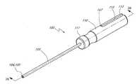
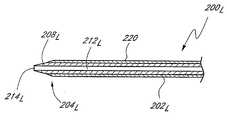
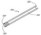
본 발명의 일 측면에 따르면, 기기를 연조직을 통해 척추상의 일 지점으로 안내하기 위한 접근 조립체가 제공된다. 상기 조립체는 긴 관형 가이드핀 안내부, 가이드 내에서 슬라이딩 가능하게 배치된 무딘 팁 탐침을 포함한다. 가이드핀은 또한 가이드핀 안내부 내에 슬라이딩 가능하게 배치된다. 가이드핀은 경사진 말단 및 기부 핸들을 포함할 수 있다. 핸들은 가이드핀에 의해 제거가능하게 운반될 수 있다. 탐침은 기부 핸들을 포함할 수 있다.According to one aspect of the invention, there is provided an access assembly for guiding a device through a soft tissue to a point on the spine. The assembly includes an elongated tubular guide pin guide, a blunt tip probe slidably disposed within the guide. The guide pin is also slidably arranged in the guide pin guide. The guide pin may include an inclined end and a base handle. The handle may be removable by the guide pin. The probe may include a base handle.
가이드핀은 뾰족한 말부 팁을 포함할 수 있다. 탐침 상의 기부 핸들은 가이드핀 안내부와 해제가능하게 결합될 수 있다. 가이드핀은 가이드핀 연장부에의 연결을 위한 기부 커넥터를 포함할 수 있다. 탐침의 말단은 탐침이 가이드핀 안내부와 결합될 때 가이드핀 안내부의 말단 너머로 노출될 수 있다.The guide pin may comprise a pointed tip. The base handle on the probe can be releasably coupled with the guide pin guide. The guide pin may include a base connector for connection to the guide pin extension. The ends of the probe may be exposed beyond the ends of the guide pin guide when the probe is engaged with the guide pin guide.
본 발명의 다른 측면에 따르면, 가이드핀 안내부가 제공된다. 안내부는 기단, 말단 및 이를 통해 연장하는 중앙 내강을 갖는 안내부 튜브를 포함한다. 핸들은 말단 상에 제공된다. 무딘 팁 탐침은 안내부 튜브 내에서 축방향으로 이동하도록 배치된다. 잠금부는 안내부 튜브 내에서 탐침을 해제가능하게 유지하도록 제공된다.According to another aspect of the invention, a guide pin guide is provided. The guide includes a guide tube having a proximal end, a distal end, and a central lumen extending therethrough. The handle is provided on the end. The blunt tip probe is arranged to move axially within the guide tube. The lock is provided to releasably hold the probe in the guide tube.
탐침의 무딘 팁은, 탐침이 안내부 튜브 내에서 잠겨있을 때, 말단 너머로 노출될 수 있다. 잠금부는, 탐침에 의해 운반되는 제1 면 구조를 포함하고, 안내부 튜브에 의해 운반된 제2 상보 면 구조와 해제가능하게 결합된다. 제1 및 제2 면 구조 중 하나는 핀을 포함할 수 있고, 제1 및 제2 면 구조 중 다른 하나는 슬롯을 포함할 수 있다. 안내부 튜브는 경사진 팁을 포함한다.The blunt tip of the probe may be exposed beyond the distal end when the probe is locked in the guide tube. The lock includes a first face structure carried by the probe and is releasably coupled with a second complementary face structure carried by the guide tube. One of the first and second face structures may comprise a pin and the other of the first and second face structures may include a slot. The guide tube includes an inclined tip.
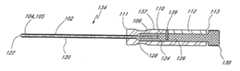
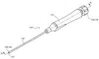
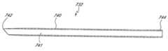
본 발명의 일 측면에 따르면, 기기를 연 조직 통로를 따라 척추의 일 지점으로 안내하는 가이드핀이 제공된다. 가이드핀은 기단 및 말단을 갖는 긴 로드를 포함한다. 뾰족한 팁은 말단 상에 제공된다. 핸들은 기단에 의해 해제가능하게 운반된다. 회전정렬 가이드는 핸들에 관한 소정의 회전 방위 내로 가이드핀을 유지하도록 제공된다.According to one aspect of the invention, a guide pin is provided that guides the device along a soft tissue passageway to a point on the spine. The guide pin includes a long rod having a proximal and distal end. The pointed tip is provided on the end. The handle is releasably carried by the base. A rotational alignment guide is provided to hold the guide pin into a predetermined rotational orientation relative to the handle.
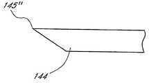
가이드핀은, 가이드핀의 회전방위를 지시하기 위하여 핸들 상에 표시부를 더 포함한다. 해제가능한 결합이 상기 로드와 상기 핸들 사이에 제공된다. 상기 뾰족한 팁은 2면 또는 3면 경사부를 포함한다. 대안적으로 상기 뾰족한 팁은 2면 경사부를 포함할 수 있다. 가이드핀은 안내부 튜브에 의해 운반되는 제2 상보면 구조와 해제가능한 맞물림을 위한 제1 상보면 구조를 더 포함할 수 있다.The guide pin further includes a display portion on the handle to indicate the rotational direction of the guide pin. A releasable engagement is provided between the rod and the handle. The pointed tip includes a two or three side slope. Alternatively, the pointed tip may comprise a two side slope. The guide pin may further comprise a first complementary surface structure for releasable engagement with a second complementary surface structure carried by the guide tube.
본 발명의 다른 측면에 따르면, 꼬리쪽 접근을 통해 엉치뼈 전방 면의 일 지점으로 전진시키는 가이드핀이 제공된다. 기이드핀은 기단 및 말단을 갖는 긴 본체를 포함한다. 방사상 비대칭한 포인트 팁이 말단 상에 제공될 수 있다. 표시부는 포인트 팁의 방위가 표시부의 방위에 의해 결정되도록, 본체의 회전방위의 기단에 의해 운반된다. 표시부는 홈(groove), 선(line), 점(dot), 또는 다른 시각 또는 촉각적 표시부로 될 수 있다.According to another aspect of the invention, a guide pin is provided for advancing to a point on the anterior surface of the sacrum through a tail-side approach. The guide pin includes an elongated body having a proximal end and a distal end. Radially asymmetric point tips may be provided on the ends. The display portion is carried by the proximal end of the rotational direction of the main body such that the orientation of the point tip is determined by the orientation of the display portion. The display may be a groove, a line, a dot, or other visual or tactile display.
가이드핀은 가이드핀 이송 조립체를 만들기 위하여 가이드핀 안내부 튜브와 조합될 수 있다. 핀은 약 11인치(inch) - 약 13인치(inch)의 길이범위를 가질 수 있다. 포인트 핀은 2면 쐐기부(wedge), 3면 쐐기부, 1면 경사부로 형성된 기울어진 표면을 포함할 수 있다. 표면은 가이드핀의 종축을 따라 약30도-약60도 범위의 각도에 있을 수 있다.The guide pin can be combined with the guide pin guide tube to make the guide pin transfer assembly. The pin may have a length ranging from about 11 inches to about 13 inches. The point pin may comprise an inclined surface formed of two-sided wedges, three-sided wedges, and one-sided slopes. The surface may be at an angle in the range of about 30 degrees to about 60 degrees along the longitudinal axis of the guide pin.
가이드핀은 가이드핀의 기단에 결합된 상기 가이드핀 핸들을 더 포함할 수 있다. 핸들은 상기 가이드핀에 해제가능하게 결합될 수 있고, 회전방위의 상기 표시부는 상기 핸들에 의해 운반될 수 있다.The guide pin may further include the guide pin handle coupled to the proximal end of the guide pin. The handle may be releasably coupled to the guide pin, and the indicator of the rotational direction may be carried by the handle.
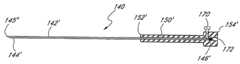
가이드핀은 가이드핀 안내부 튜브; 및 가이드핀과 안내부 튜브 사이의 해제가능한 내부잠금부를 더 포함할 수 있다. 상기 가이드핀의 길이는, 해제가능한 잠금부가 맞물릴 때, 안내부 튜브의 길이에 관한 치수를 가지며, 상기 가이드핀 상의 포인트 팁이 안내부 튜브의 말단 너머로 연장될 수 있다. 가이드핀은 가이드핀 및 가이드핀 안내부 튜브의 회전 정렬을 유지하기 위해, 제2 회전 정렬면을 상기 가이드핀 안내부 튜브에 접촉시키는 적어도 하나의 회전 정렬면을 더 포함할 수 있다. 제1 회전 정렬면은 축방향으로 연장되는 평면을 포함할 수 있다.Guide pins are guide pin guide tube; And a releasable inner lock between the guide pin and the guide tube. The length of the guide pin is dimensioned with respect to the length of the guide tube when the releasable lock is engaged, and the point tip on the guide pin can extend beyond the end of the guide tube. The guide pin may further include at least one rotational alignment surface for contacting the second rotational alignment surface with the guide pin guide tube to maintain the rotational alignment of the guide pin and the guide pin guide tube. The first rotational alignment surface may comprise a plane extending in the axial direction.
가이드핀은 상기 가이드핀 연장부에 해제가능한 결합을 위해 가이드핀의 기단 상의 해제가능한 커플링을 더 포함할 수 있다. 상기 커플링은 헬리컬 나사산을 포함할 수 있고, 축방향으로 연장되는 공동을 포함할 수 있다.The guide pin may further include a releasable coupling on the proximal end of the guide pin for releasable coupling to the guide pin extension. The coupling may comprise a helical thread and may comprise an axially extending cavity.
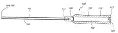
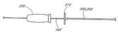
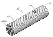
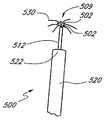
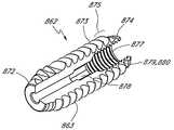
본 발명의 일 측면에 따르면, 축방향을 연장된 접근 내강을 따라 적어도 하나의 척추 본체를 거쳐 목표 디스크 공간에 도달하는 삽입을 위해 조정되는 척추 핵조직 추출도구가 제공된다. 조직추출도구는 긴 관형 덮개; 기단 및 말단을 가지고, 덮개 내에서 축방향으로 이동되도록 배치되는 긴 샤프트를 포함한다. 조직추출헤드 샤프트의 말단 상에 제공된다. 조직추출헤드는 바람직하게는 복수의 필라멘트 예로 적어도 2 개의 비선형 필라멘트를 포함할 수 있다. 어떤 실시예로서 조직추출헤드는 복수의 꼬인 와이어, 풀린 와이어 끈(braid) 또는 코일을 포함한다. 어떤 실시예는 적어도 약 10 필라멘트 및 다른 실시예는 적어도 약 20 필라멘트를 포함한다. 추출헤드는 덮개 내로 신축되는 제1 위치 및 덮개의 말단 너머로 노출되는 제2 위치 사이에서 축방향으로 이동가능하다.According to one aspect of the invention, there is provided a spinal nucleus extraction tool that is adapted for insertion to reach a target disk space through at least one spinal body along an axially extending access lumen. The tissue extraction tool includes a long tubular cover; An elongated shaft having a proximal end and a distal end, the elongated shaft being arranged to move axially within the cover. It is provided on the end of the tissue extraction head shaft. The tissue extraction head may preferably comprise a plurality of filaments, for example at least two nonlinear filaments. In some embodiments, the tissue extraction head includes a plurality of twisted wires, loose wire braids, or coils. Some embodiments include at least about 10 filaments and other embodiments include at least about 20 filaments. The extraction head is axially movable between a first position that extends into the lid and a second position that is exposed beyond the distal end of the lid.
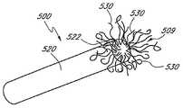
본 발명의 다른 측면에 따르면, 조직제거도구가 제공된다. 조직제거도구는 기단 및 말단을 갖는 긴 관형 덮개 및 상기 덮개 내에서 축방향으로 이동되도록 배치되는 긴 샤프트를 포함한다. 복수의 꼬인 필라멘트는 샤프트의 말단에 의해 운반되며, 샤프트가 관형 덮개내에서 필라멘트를 배치하도록 기부쪽으로 신축될 때의 제1 감소 횡단면 형상 및 샤프트가 덮개에 관해 축방향으로 말부로 전진될 때, 덮개의 말단 너머로 필라멘트를 노출하도록 제2 확장 횡면적 형상 사이에서 이동가능하다. 필라멘트는, 필라멘트가 상기 제1형상일 때, 덮개의 종축을 따라 실질적으로 평행하다. 필라멘트는, 샤프트가 상기 제2형상일 때, 임의로 조직된다. 조직제거도구는 적어도 10 필라멘트를 포함하며, 종종 약 5-40 필라멘트의 범위를 포함한다. 필라멘트는 니켈 티타늄 합금 또는 스테인리스 스틸과 같은 금속으로 이루어진다. 각 필라멘트는 약 0.05 "(인치)보다 크지 않는 직경 또는 약 0.02"(인치)보다 크지 않는 직경을 가진다.According to another aspect of the present invention, a tissue removal tool is provided. The tissue removal tool includes an elongated tubular sheath having a proximal and distal end and an elongated shaft arranged to move axially within the sheath. The plurality of twisted filaments are carried by the ends of the shaft, with the first reduction cross-sectional shape when the shaft is stretched toward the base to place the filament in the tubular sheath and when the shaft is advanced axially with respect to the sheath. Moveable between the second enlarged cross sectional shape to expose the filament beyond the distal end of; The filaments are substantially parallel along the longitudinal axis of the lid when the filaments are in the first shape. The filaments are optionally organized when the shaft is in the second shape. The tissue removal tool includes at least 10 filaments, often in the range of about 5-40 filaments. The filament is made of a metal such as nickel titanium alloy or stainless steel. Each filament has a diameter no greater than about 0.05 "(inch) or a diameter no greater than about 0.02" (inch).
본 발명의 다른 측면에 따르면, 목표 디스크 공간 내로의 삽입을 조정하는 척추조직추출도구가 제공된다. 상기 도구는 긴 관형 덮개; 및 기단 및 말단을 갖고, 상기 덮개 내에서 이동가능하도록 배치되는 긴 샤프트를 포함한다. 조직추출헤드는 상기 샤프트의 말단 상에 제공되고, 상기 추출헤드는 목표 디스크 공간에서 조직을 맞물림 및 제거하는 복수의 비평형 필라멘트를 포함한다. 상기 추출헤드는 복수의 와이어를 포함하며, 이는 임의로 정렬된다. 상기 도구는 추가적으로 샤프트 기단 상의 핸들을 포함하며, 상기 도구는 추간판 공간에 안내되어 사용되도록 치수가 정해질 수 있다.According to another aspect of the present invention, there is provided a spinal tissue extraction tool that coordinates insertion into a target disk space. The tool includes a long tubular cover; And an elongated shaft having a proximal end and a distal end, the elongated shaft being arranged to be movable within the cover. A tissue extraction head is provided on the end of the shaft, the extraction head comprising a plurality of non-equilibrium filaments that engage and remove tissue in the target disk space. The extraction head comprises a plurality of wires, which are arbitrarily aligned. The tool additionally includes a handle on the shaft proximal and the tool can be dimensioned to be guided and used in the intervertebral disc space.
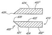
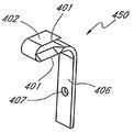
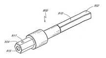
본 발명의 일 측면에 따르면, 추간판 공간의 물질을 분리시키는 커터가 제공된다. 커터는 커터 블레이드, 인접한 척추종판을 배치하기 위한 커터 블레이드 상의 제1면 및 블레이드 두께에 의해 제1면에서 분리되는 블레이드의 제2면을 포함한다. 커터는 블레이드의 제1측면, 블레이드의 제2측면 및 적어도 하나의 상기 제1 및 제2 측면 상의 적어도 하나의 절단 가장자리를 가진다.According to one aspect of the invention, a cutter is provided that separates material in the intervertebral disc space. The cutter includes a cutter blade, a first face on the cutter blade for placing adjacent endplates and a second face of the blade separated from the first face by the blade thickness. The cutter has a first side of the blade, a second side of the blade and at least one cutting edge on at least one of the first and second sides.
절단 가장자리는 상기 제1면과 동일 평면에 있거나, 상기 제2면과 동일 평면에 있을 수 있다. 대안적으로, 절단 가장자리는 상기 제1면과 제2면 사이 안에 배치되는 평면의 중앙에 있을 수 있다. 커터는 제1측면의 제1절단 가장자리 및 상기 제2측면의 제2절단 가장자리를 포함할 수 있다. 블레이드는 긴 리본을 포함하며, 회전축에서 방사상 외측으로 기울어질 수 있다. 리본은 밴드를 포함하며, 리본은 자체적으로 접어서 젖힐 수 있다. 리본은 제1단 및 제2단을 포함하며, 적어도 하나의 제1단은 회전가능한 드라이브 샤프트에 부착되는 부착구조를 포함할 수 있다. 부착구조는 개구(aperture)를 포함할 수 있다. 일 실시예로서 제1단과 제2단 모두는 회전가능한 드라이브 샤프트에 결합되도록 조정된다. 블레이드는 회전축에서 방사상 외측으로 연장되고, 말부 방향으로 기울어질 수 있다. 대안적으로, 블레이드는 기부 방향에서 회전축의 방사상 외측으로 기울어질 수 있다. 커터는 바람직하게는 회전가능한 드라이브 샤프트에 고정된다.The cutting edge may be coplanar with the first face or coplanar with the second face. Alternatively, the cutting edge may be in the center of a plane disposed between the first and second surfaces. The cutter may include a first cutting edge of the first side and a second cutting edge of the second side. The blade comprises an elongated ribbon and can be tilted radially outwards on the axis of rotation. The ribbon includes a band, and the ribbon can be folded over itself. The ribbon includes a first end and a second end, and the at least one first end may comprise an attachment structure attached to the rotatable drive shaft. The attachment structure may comprise an aperture. In one embodiment both the first and second ends are adjusted to engage the rotatable drive shaft. The blade extends radially outwardly on the axis of rotation and can be tilted in the terminal direction. Alternatively, the blade can be tilted radially outward of the axis of rotation in the base direction. The cutter is preferably fixed to the rotatable drive shaft.
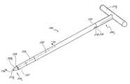
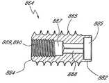
본 발명의 다른 측면에 따르면, 분리 장치가 제공된다. 분리장치는 단부 요소에 해제가능하게 결합되는 적어도 하나의 기부를 갖는 긴 본체를 포함한다. 기부 요소 상의 기부 나사산은 제1 피치 및 제1 주 직경을 가지며, 단부 요소 상의 단부 나사산은 제2 피치 및 제2 주 직경을 가진다. 상기 제1 피치는 상기 제2 피치와 다르고, 상기 제1 주 직경은 상기 제2 주 직경보다 크다.According to another aspect of the invention, a separation device is provided. The separator includes an elongated body having at least one base releasably coupled to the end element. The base thread on the base element has a first pitch and a first major diameter, and the end thread on the end element has a second pitch and a second major diameter. The first pitch is different from the second pitch, and the first major diameter is greater than the second major diameter.
제1 주 직경은 약 10mm - 약 15mm 의 범위 내 일 수 있다. 제2 주 직경은 상기 제1 주 직경의 약 98%보다 크지 않을 수 있다. 긴 본체는 약 1.25 인치 - 약 2.25 인치의 범위의 길이를 가질 수 있다. 기부 나사산 및 말부 나사산 각각은 약 0.5 인치 - 약 1.25 인치 범위의 축 길이를 가질 수 있다. 상기 장치는 기부 요소 및 말부 요소 사이에 상보 나사산이 형성된 면을 포함할 수 있다. 긴 본체는 스테인리스 스틸, 티타늄 또는 다른 물질로 이루어질 수 있다. 어떤 실시예로서 기부 나사산 및 상기 단부 나사산의 각각은 말부 방향에서 기부를 볼 때, 상기 본체 둘레로 반시계방향으로 연장될 수 있다. 대안적으로 기부 나사산 및 상기 단부 나사산의 각각은, 말부 방향에서 기부를 볼 때, 상기 본체 둘레로 시계방향으로 연장될 수 있다. 제2 피치는 제1 피치의 적어도 약 105%일수 있고, 제2 피치는 제1 피치의 적어도 약 110%일 수 있고, 제2 피치는 제1 피치의 적어도 약 125%일 수 있다. 상기 장치는 회전가능한 드라이버 도구와 해제가능하게 맞물림되기 위하여, 해제가능한 커플링을 더 포함할 수 있다.The first major diameter may be in the range of about 10 mm to about 15 mm. The second major diameter may not be greater than about 98% of the first major diameter. The long body may have a length in the range of about 1.25 inches to about 2.25 inches. Each of the base and end threads may have an axial length in the range of about 0.5 inches to about 1.25 inches. The device may comprise a surface with complementary threads formed between the base element and the terminal element. The elongate body may be made of stainless steel, titanium or other materials. In some embodiments, each of the base thread and the end thread may extend counterclockwise around the body when viewing the base in the distal direction. Alternatively each of the base thread and the end thread may extend clockwise around the body when viewing the base in the distal direction. The second pitch may be at least about 105% of the first pitch, the second pitch may be at least about 110% of the first pitch, and the second pitch may be at least about 125% of the first pitch. The device may further comprise a releasable coupling to releasably engage with the rotatable driver tool.
본 발명의 다른 측면에 따르면, 임시분리장치가 제공된다. 상기 장치는 적어도 하나의 기부 요소 및 말부 요소를 갖는 긴 본체를 포함한다. 나사산에 맞물리는 기부 뼈가 기부 요소 상에 제공되고, 나사산에 맞물리는 말부 뼈가 나사에 맞물리는 기부 뼈로부터 축방향으로 분리되는 말부 요소 상에 제공된다. 회전가능한 드라이버를 포함하며, 회전가능한 드라이버의 회전은, 나사산에 맞물리는 기부 및 말부 뼈사이에서 축 분리를 변경한다. 임시 분리장치는 회전가능한 드라이버에 해제가능하게 맞물림하기 위하여, 해제가능한 커플링을 포함한다.According to another aspect of the present invention, a temporary separation device is provided. The device comprises an elongated body having at least one base element and a terminal element. A base bone that engages the thread is provided on the base element, and a terminal bone that engages the thread is provided on the horse element that is axially separated from the base bone that engages the screw. A rotatable driver, wherein the rotation of the rotatable driver alters the axial separation between the base and the end bones that engage the threads. The temporary detachment device includes a releasable coupling to releasably engage a rotatable driver.
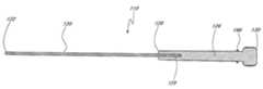
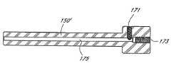
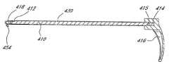
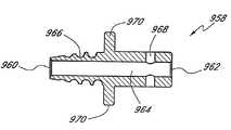
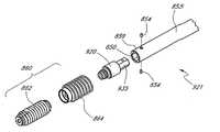
본 발명의 일 측면에 따르면 연 조직(soft tissue)을 통해 뼈 표면으로 가는 접근 경로의 횡단면 영역을 증가시키는 교환시스템이 제공된다. 교환시스템은 기단, 말단 및 이를 통해 연장되는 중앙 내강을 갖는, 긴 관형 교환 부싱을 포함한다. 기단, 말단 및 이를 통해 연장되는 중앙 내강, 경사진 말단을 포함하는 교환 삽입관을 갖는, 긴 관형 교환 삽입관이 제공된다. 교환 부싱은 교환 삽입관의 중앙 내강 내에서 축 상으로 슬라이딩 가능하다.According to one aspect of the invention there is provided an exchange system that increases the cross sectional area of the access path to the bone surface through soft tissue. The exchange system includes an elongated tubular exchange bushing having a proximal end and a central lumen extending therethrough. An elongated tubular exchange insert tube is provided having an exchange insert tube comprising a proximal end, a distal end, and a central lumen, inclined end extending therefrom. The exchange bushing is slidably axially within the central lumen of the exchange insert.
경사부는 교환 삽입관의 종축에 관해, 약 20도 - 약 70도 범위의 각도에 있을 수 있다. 어떤 실시예로서 경사부는 교환 삽입관의 종축에 관해, 약 30도 - 약60도 범위의 각도에 있다. 핸들은 교환 삽입관의 기단 상에 제공된다.The incline may be at an angle in the range of about 20 degrees to about 70 degrees with respect to the longitudinal axis of the replacement cannula. In some embodiments, the inclined portion is at an angle in the range of about 30 degrees to about 60 degrees with respect to the longitudinal axis of the replacement cannula. The handle is provided on the proximal end of the exchange cannula.
교환시스템은 경사부의 회전 방위의 표시부를 더 포함한다. 표시부는 교환 삽입관의 기단에 식별가능한 마커를 더 포함한다. 일 이행 예로서, 표시부는 교환 삽입관의 기단에 의해 운반되는 환형 밴드 상에 적어도 하나의 노치를 포함한다.The exchange system further includes an indication of the rotational orientation of the inclined portion. The indicator further includes an identifiable marker at the base of the exchange cannula. As one implementation example, the indicator includes at least one notch on an annular band carried by the proximal end of the exchange cannula.
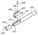
교환시스템은 교환 삽입관의 말단에서 말부로 연장되고, 제1 감소외경 구성과 제2 확대외경 구성 사이에서 이동가능한 복수의 핑거부를 더 포함할 수 있다. 교환 부싱은, 제1 감소외경 상태에서, 핑거부들을 수용하는 여유부(recess)를 가질 수 있다.The exchange system may further comprise a plurality of fingers extending end to end of the exchange cannula and movable between the first reduced outer diameter configuration and the second enlarged outer diameter configuration. The exchange bushing may, in the first reduced outer diameter state, have a recess for receiving the finger portions.
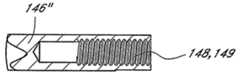
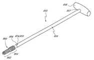
본 발명의 일 측면에 따르면, 뼈를 통해 구멍의 직경을 확장하는 뼈확장 시스템이 제공된다. 뼈확장 시스템은 기단 및 말단을 갖는 제1 삽입관 로드를 포함한다. 핸들은 기단 상에 제공된다. 관삽입된 로드 및 슬랩해머를 통해 연장하는 가이드핀 너머의 상호 운동을 위한, 관삽입된 슬랩해머를 포함한다. 뼈확장 시스템은 가이드핀을 포함한다. 제1 삽입관 로드의 말단은 테이퍼 팁(tapered tip)을 수반하여 제공된다. 상기 시스템은 제1 삽입관 로드보다 더 큰 직경을 갖는, 적어도 하나의 제2 삽입관 로드를 더 포함할 수 있다. 상기 시스템은 제2 삽입관 로드보다 더 큰 직경을 갖는, 적어도 하나의 제3 삽입관 로드를 더 포함할 수 있다. 상기 시스템은 관형 덮개 내에 제거가능하게 배치되는 적어도 하나의 삽입관 로드를 포함할 수 있다. 상기 시스템은 로드에 덮개를 해제가능하게 부착하기 위하여, 덮개 상의 제 1 보유구조 및 삽입관 로드 상의 제2 상보 보유구조를 더 포함할 수 있다.According to one aspect of the invention, there is provided a bone dilation system for expanding the diameter of a hole through a bone. The bone dilator system includes a first cannula rod having a proximal and distal end. The handle is provided on the base. And a tubed slab hammer for mutual movement beyond the guide pin extending through the tubed rod and the slab hammer. The bone dilator system includes a guide pin. The distal end of the first cannula rod is provided with a tapered tip. The system may further include at least one second insert tube rod having a larger diameter than the first insert tube rod. The system may further comprise at least one third cannula rod having a larger diameter than the second cannula rod. The system may include at least one cannula rod removably disposed within the tubular sheath. The system may further comprise a first retaining structure on the cover and a second complementary retaining structure on the cannula rod to releasably attach the cover to the rod.
본 발명의 다른 측면에 따르면, 뼈를 통해 구멍의 직경을 증가시키는 뼈확장기 키트가 제공된다. 상기 키트는 기부 핸들 및 제1 확장기를 갖는 제1 삽입관 로드를 포함한다. 기부 핸들 및 제2 확장기를 갖는 제2 삽입관 로드가 제공된다. 기부 핸들 및 제3 확장기를 갖는 제3 삽입관 로드가 제공된다.According to another aspect of the present invention, there is provided a bone expander kit for increasing the diameter of a hole through a bone. The kit includes a first cannula rod having a base handle and a first dilator. A second cannula rod is provided having a base handle and a second dilator. A third cannula rod is provided having a base handle and a third dilator.
상기 키트는 슬랩해머를 더 포함할 수 있다. 제1, 제2, 제3 직경의 적어도 하나는 약 6mm이다. 제1, 제2, 제3 직경의 적어도 하나는 약 8mm이다. 제1, 제2, 제3 직경의 적어도 하나는 약 10mm이다. 상기 키트는 적어도 하나의 삽입관 로드를 축방향으로 슬라이딩 가능하게 수용하도록 치수가 정해진 중앙 내강을 갖는 관형 덮개를 더 포함할 수 있다. 적어도 하나의 로드 상에 덮개를 해제가능하게 보유하는 잠금부가 제공된다.The kit may further comprise a slab hammer. At least one of the first, second, and third diameters is about 6 mm. At least one of the first, second, and third diameters is about 8 mm. At least one of the first, second, and third diameters is about 10 mm. The kit may further comprise a tubular cover having a central lumen dimensioned to slidably receive the at least one insert tube rod. A lock is provided that releasably holds the lid on at least one rod.
본 발명에 개시된 외과수술용 도구세트 및 기술의 이러한 및 다른 유리한 점 및 특징은, 수반되는 특징들과의 관련성을 고려할 때 후술되는 바람직한 실시예의 상세한 설명에서 보다 용이하게 설명될 것이다.These and other advantages and features of the surgical instruments and techniques disclosed herein will be more readily described in the detailed description of the preferred embodiments described below, given the relevance of the accompanying features.
도 1a는 정상적인 척주의 측면도이고,1A is a side view of a normal spinal column,
도 1b는 척추 디스크의 정상, 퇴행, 팽창, 탈출 및 얇은 상태를 나타내는 개략도이고,1B is a schematic diagram showing normal, degenerative, dilatation, escape and thinning of a vertebral disc,
도 1c는 머리방향 및 척추후궁절제술의 목표지점의 전방 축 방향으로 연장된, 시각화된 전방 축 기구/이식물 선(AAIIL) 을 묘사한 척주의 천골부 및 요추의 측면도이고,FIG. 1C is a side view of the sacrum and lumbar spine of the spinal column depicting a visualized anterior axial instrument / graft line (AAIIL) extending in the anterior axial direction of the target point of head and spinal resection.
도 1d는 천골의 전방 목표지점을 나타내며,1d shows the anterior target point of the sacrum,
도 1e 및 도 1f는 도 1c의 시각화된 AAIIL선에 평행하게 형성된 TASII 구멍에 각각 대응하는 하나 및 두개의 대향 천골축 이식을 나타내는 요추의 꼬리방향 단면도이고,1E and 1F are tail cross-sectional views of the lumbar spine showing one and two opposing sacral shaft grafts corresponding to TASII holes formed parallel to the visualized AAIIL line of FIG. 1C, respectively;
도 2a 및 도 2b는 각각 핀과 슬롯 구성을 가진 가이드핀 안내부의 일 실시예의 사시도 및 측 횡단면도이고,2A and 2B are perspective and side cross-sectional views of one embodiment of a guide pin guide having a pin and slot configuration, respectively;
도 2c는 핀 구성을 가진 탐침의 일 실시예의 측 횡단면도이고,2C is a side cross-sectional view of one embodiment of a probe with a fin configuration,
도 2d는 가이드핀 안내부-탐침-핀 및 슬롯으로 구성된 조립체의 사시도이고,2D is a perspective view of the assembly consisting of guide pin guide-probe-pin and slots,
도 2e는 도 2d의 조립체의 측 횡단면도이고,2E is a side cross-sectional view of the assembly of FIG. 2D,
도 3a는 가이드핀 안내부의 일실시예의 측 횡단면도이고,3A is a side cross-sectional view of one embodiment of a guide pin guide,
도 3b는 도 3a의 가이드핀 안내부의 측 횡단면도이고,Figure 3b is a side cross-sectional view of the guide pin guide of Figure 3a,
도 3c는 다중 개시 나사산 구성을 가진 탐침의 일 실시예의 측 횡단면도이고,3C is a side cross-sectional view of one embodiment of a probe with a multi-start thread configuration,
도 3d는 안내부-탐침-다중 개시 나사산으로 구성된 일 실시예의 사시도이고,3D is a perspective view of one embodiment consisting of a guide-probe-multiple start thread,
도 3e는 도 3d의 조립체의 측 횡단면도이고,3E is a side cross-sectional view of the assembly of FIG. 3D,
도 4 및 도 5는 척추 본체 S1의 전방 면으로 가이드핀 안내부-탐침-조립체 말단의 이송을 나타내는 척추의 요추 및 엉치뼈 부분의 측면 부분 횡단면도이고,4 and 5 are side cross-sectional side views of the lumbar and sacrum portions of the vertebrae showing the transfer of the guide pin guide-probe-assembly end to the anterior side of the vertebral body S1, FIGS.
도 6a는 말단 및 기단을 나타내는 가이드핀의 측면도이고,Figure 6a is a side view of the guide pin showing the distal and proximal ends,
도 6b는 투관침(trocar) 팁을 갖는 가이드핀의 일 실시예의 말단의 측면도이고,6B is a side view of the distal end of one embodiment of a guide pin with a trocar tip,
도 6c는 경사진 팁 구성을 갖는 가이드핀의 일 실시예의 말단의 측면도이고,6C is a side view of the distal end of one embodiment of a guide pin having an inclined tip configuration;
도 6d는 팁 정렬 및 축 잠금과 회전 잠금의 수단으로서, 6각 및 평면 구성을 갖는 가이드핀의 바람직한 실시예의 기단의 측면도이고,6D is a side view of the proximal end of a preferred embodiment of a guide pin having a hexagonal and planar configuration, as a means of tip alignment and axial locking and rotational locking,
도 7a는 가이드핀-가이드핀 핸들 조립체의 횡단면도이고,7A is a cross sectional view of a guide pin-guide pin handle assembly,
도 7b는 가이드핀 핸들의 횡 단면도이고,7B is a cross sectional view of the guide pin handle;
도 7c는 가이드핀을 잠그기 위한 손잡이 스크류를 나타내며,7c shows the handle screw for locking the guide pin,
도 7d는 가이드핀의 정지 및 조종을 위한 수단을 나타내며,7d shows the means for stopping and manipulating the guide pin,
도 7e는 안내부의 말단 너머로 연장되는 가이드핀 팁을 나타내는 안내부 내에 삽입된 가이드핀 조립체를 나타내며,FIG. 7E shows a guide pin assembly inserted in a guide showing a guide pin tip extending beyond the distal end of the guide,
도 7f는 가이드핀을 수반한 해제가능한 결합을 보여주는, 가이드핀 핸들 조립체를 나타내는 가이드핀 핸들을 도시한 횡 단면도이고,7F is a cross sectional view of the guide pin handle showing the guide pin handle assembly showing a releasable engagement with guide pins;
도 8a는 나사산 맞물림 커플링을 수반하는 가이드핀-가이드핀 연장부 조립체를 나타내며,8A shows a guide pin-guide pin extension assembly with threaded engagement coupling,
도 8b는 나사산 맞물림 커플링을 수반한 가이드핀-가이드핀 연장부 조립체의 상세도이고,8B is a detail view of the guide pin-guide pin extension assembly with threaded engagement coupling,
도 8c는 암나사산 맞물림 커플링의 횡단면도를 수반한 가이드핀을 나타내며,8c shows a guide pin with a cross-sectional view of a female thread engagement coupling,
도 8d는 도 8c의 암나사산 맞물림 커플링의 확대도이고,FIG. 8D is an enlarged view of the female thread engagement coupling of FIG. 8C;
도 8e는 수나사산 맞물림 커플링의 횡단면도를 수반하는 가이드핀 연장부를 도시하며,8E shows a guide pin extension with a cross sectional view of the male threaded engagement coupling,
도 8f는 도 8e의 수나사산 맞물림의 확대도이고,8F is an enlarged view of the male thread engagement of FIG. 8E,
도 8g는 마찰맞춤 맞물림 커플링을 갖는 가이드핀-가이드핀 연장부 조립체의 대안적인 실시예를 나타내며,FIG. 8G shows an alternative embodiment of a guide pin-guide pin extension assembly with a friction engagement engagement coupling,
도 9는 연장된 가이드핀 상의 슬랩 해머 및 확장자의 측면도이고,9 is a side view of the slab hammer and extension on an extended guide pin,
도 10은 3 가지 다른 크기의 확장기의 입면도이고,10 is an elevation view of three different size expanders,
도 11은 확장기의 일 실시예의 사시도이고,11 is a perspective view of one embodiment of the dilator,
도 12는 도 11의 확장기의 말 부의 측면 횡 단면도이고,12 is a side cross-sectional view of the end of the dilator of FIG. 11,
도 13a는 확장기 덮개를 갖는 큰 확장기의 일 실시예의 사시도이고,13A is a perspective view of one embodiment of a large expander with an expander cover,
도 13b는 도 13a의 확장기 덮개 내의 큰 확장기 말부의 측면 횡 단면도이고,FIG. 13B is a side transverse cross-sectional view of the large dilator end in the dilator cover of FIG. 13A,
도 13c는 도 13a의 큰 확장기의 덮개의 사시도이고,FIG. 13C is a perspective view of the lid of the large expander of FIG. 13A,
도 13d는 큰 확장기 덮개의 다른 실시예의 사시도이고,13D is a perspective view of another embodiment of a large expander cover,
도 14는 비틀림 드릴의 일 실시예의 측면도이고,14 is a side view of one embodiment of a torsion drill,
도 15는 L5-S1 디스크 공간의 확장기 덮개(도킹 삽입관)를 통해 연장하는 커터를 나타내며,15 shows a cutter extending through the expander cover (docking insert) of L5-S1 disk space,
도 16a는 하부 커터를 구성하는 커터 조립체의 일 실시예의 사시도이고,16A is a perspective view of one embodiment of a cutter assembly constituting a lower cutter,
도 16b는 도 16a의 커터 조립체의 측면 횡단면도이고,16B is a side cross-sectional view of the cutter assembly of FIG. 16A;
도 16c는 도 16a의 커터 조립체의 말부의 전개 사시도이고,16C is an exploded perspective view of the end of the cutter assembly of FIG. 16A;
도 16d 및 도 16e는 작은 하부 커터의 일 실시예의 입면도이고,16D and 16E are elevation views of one embodiment of a small lower cutter,
도 16f는 도 16e의 16F-16F선을 따른 이동보존과정에 앞서 핵제거를 위한 기부 커터 블레이드 아암(402')의 횡단면도이고,FIG. 16F is a cross sectional view of the base
도 16g는 도 16e의 16F-16F선을 따른 고정술에 앞서 핵제거를 위한 깁 커터 블레이드 아암(402')의 횡단면도이고, (경사면(421)은 도 16f의 거울 이미지임)FIG. 16G is a cross sectional view of the gib
도 16h는 상부 커터(452)의 일 실시예를 나타내며,16H shows one embodiment of an
도 16i는 조직 커터를 위한 신축 멈춤 매카니즘을 보여주는 말부 슬리브-샤프트 구성의 횡단면도이고,FIG. 16I is a cross-sectional view of a terminal sleeve-shaft configuration showing the stretch stop mechanism for a tissue cutter,
도 17a는 디벌커를 구성하는 커터 조립체의 말부의 전개 사시도이고,17A is an exploded perspective view of the end of the cutter assembly constituting the debulker,
도 17b 및 도 17c는 도 17a의 커터 조립체의 디벌커의 입면도이고,17B and 17C are elevation views of the debulker of the cutter assembly of FIG. 17A, and
도 17d 및 도 17e는 큰 디벌커의 일 실시예의 입면도이고,17D and 17E are elevation views of one embodiment of a large debulker,
도 18a는 큰 눈물방울 디벌커의 일 실시예의 입면도이고,18A is an elevation view of one embodiment of a large teardrop debulker,
도 18b는 회전가능한 샤프트에 부착되는 도 18a의 눈물방울 디벌커 부의 배면도이고,FIG. 18B is a rear view of the teardrop debulker portion of FIG. 18A attached to the rotatable shaft, FIG.
도 18c는 도 18a의 큰 눈물방울 디벌커의 다른 입면도이고,18C is another elevation view of the large teardrop debulker of FIG. 18A,
도 18d는 표준 또는 중간 크기의 눈물방울 디벌커의 일 실시예의 입면도이고,18D is an elevation view of one embodiment of a standard or medium sized teardrop debulker,
도 18e는 큰 눈물방울 하부 커터의 일 실시예의 측면 등거리도이고,18E is a side isometric view of one embodiment of a large teardrop lower cutter,
도 18f는 중간 눈물방울 하부 커터의 일 실시예의 측면 등거리도이고,18F is a side isometric view of one embodiment of a middle teardrop lower cutter,
도 18g는 작은 눈물방울 하부 커터의 일 실시예의 측면 등거리도이고,18G is a side isometric view of one embodiment of a small teardrop lower cutter,
도 19a는 추출기 조립체 유니트의 일 실시예의 측면 사시도이고,19A is a side perspective view of one embodiment of an extractor assembly unit,
도 19b는 도 19a의 추출기 조립체 유니트의 측면 부분절단도이고,19B is a side cutaway view of the extractor assembly unit of FIG. 19A,
도 19c는 동 19a의 추출기 조립체 유니트의 측면 횡단면도이고,19C is a side cross-sectional view of the extractor assembly unit of FIG. 19A,
도 19d는 풀린 와이어를 갖기 전에 추출기 헤드의 측면도이고,19d is a side view of the extractor head before having the loose wire,
도 20은 와이어 끈 내에 조직 분절을 가진 추출기 도구의 일 실시예의 단말 을 나타내며,20 illustrates a terminal of one embodiment of an extractor tool with tissue segments in a wire string,
도 21a 및 도 21b는 노출된 위치 안으로 연장되고,이송 슬리버 안으로 잡아당기는 헤드를 가진 추출기 도구의 일 실시예를 나타내며,21A and 21B show one embodiment of an extractor tool having a head extending into the exposed position and pulling into the feed sliver,
도 21c및 도 21d는 연장부 내에 헤드를 가진 추출기 도구의 다른 실시예를 나타내며,21C and 21D show another embodiment of an extractor tool with a head in the extension,
도 22a 및 도 22b는 추출도구의 다른 실시예를 나타내며,22A and 22B show another embodiment of the extraction tool,
도 23a는 패킹 기기 및 이송 삽입관을 포함하는 삽입 도구 조립체의 사시도이고,23A is a perspective view of an insertion tool assembly including a packing machine and a transfer insert tube;
도 23b는 도 23a에서 이송 삽입관의 패킹 기기의 결합을 나타내며,FIG. 23B shows the engagement of the packing device of the feed insertion tube in FIG. 23A,
도 23c는 도 23a의 패킹기기의 사시도이고,Figure 23c is a perspective view of the packing machine of Figure 23a,
도 23d는 도 23a의 이송 삽입관의 사시도이고,23D is a perspective view of the feed insertion tube of FIG. 23A,
도 24a는 접착제-삽입기 조립체의 일 실시예의 사시도이고,24A is a perspective view of one embodiment of an adhesive-inserter assembly,
도 24b는 도 24a의 조립체의 측면 횡단면도이고,24B is a side cross-sectional view of the assembly of FIG. 24A,
도 25a는 동종이식 배치 도구의 일 실시예이고,25A is an embodiment of an allograft placement tool,
도 25b는 도 25a의 도구의 측면 횡 단면도이고,25B is a side cross-sectional view of the tool of FIG. 25A,
도 25c는 도 25a의 도구의 동종이식의 측면 횡 단면도이고,FIG. 25C is a side cross-sectional view of allograft of the tool of FIG. 25A, and FIG.
도 26은 교환 부싱의 측면도이고,26 is a side view of the exchange bushing,
도 27은 교환 부싱 및 교환 삽입관을 포함하는 교환시스템 조립체의 일 실시예의 측면도이고,FIG. 27 is a side view of an embodiment of an exchange system assembly including an exchange bushing and an exchange insert tube; FIG.
도 28a는 열린 구성의 상태에서, 도 27의 교환 삽입관의 일 실시예의 측면 부분절단도이고,FIG. 28A is a side cutaway view of an embodiment of the exchange insert tube of FIG. 27 in an open configuration, FIG.
도 28b는 닫힌 구성의 상태에서, 도 27의 교환 삽입관의 측면도이고,28B is a side view of the replacement cannula of FIG. 27, in a closed configuration;
도 29a 및 도 29b는 분리 장치 또는 확장기 덮개보다 큰 직경의 축방향 척추 이식물을 이송하기 위한 도 26 내지 도 28의 교환 시스템의 사용을 나타내며,29A and 29B illustrate the use of the exchange system of FIGS. 26-28 to transport an axial spinal implant of larger diameter than the separation device or dilator lid,
도 30a는 교환 부싱 및 교환 튜브를 포함하는 교환 시스템 조립체의 다른 실시예의 측면 횡단면도이고,30A is a side cross-sectional view of another embodiment of an exchange system assembly that includes an exchange bushing and an exchange tube,
도 30b는 도 30a의 교환 부싱의 측면 횡단면도이고,30B is a side cross-sectional view of the exchange bushing of FIG. 30A,
도 30c는 도 30a의 교환 튜브의 측면 횡단면도이고,30C is a side cross-sectional view of the exchange tube of FIG. 30A,
도 30d는 교환 부싱 및 교환 튜브를 포함하는 교환 시스템의 다른 실시예의 사시도이고,30D is a perspective view of another embodiment of an exchange system including an exchange bushing and an exchange tube,
도 30e는 도 30d의 교환 시스템의 저면 사시도이고,30E is a bottom perspective view of the exchange system of FIG. 30D,
도 31은 임시 분리 로드 또는 치료 지점에서 로드를 이송 또는 제거하는데 사용되는 도구의 일 실시예의 사시도이고,31 is a perspective view of one embodiment of a tool used to transport or remove a rod at a temporary separation rod or treatment point,
도 32a는 도 32a의 임시 분리로드 및 치료 지점에 로드를 이송하는데 사용되는 도구의 말부의 부분절단 사시도이고,32A is a cut away perspective view of the end of the tool used to transfer the rod to the temporary detachment rod and treatment point of FIG. 32A;
도 32b는 도 32a의 임시 분리로드 및 치료 지점에서 로드를 제거하는데 사용되는 도구의 말부의 부분절단 사시도이고,FIG. 32B is a cut away perspective view of the end of the tool used to remove the rod at the temporary detachment rod and treatment point of FIG. 32A;
도 33a는 임시 분리로드의 일 실시예의 말부의 부분절단 사시도이고,33A is a partially cut away perspective view of the end of an embodiment of a temporary separating rod,
도 33b는 도 33a의 로드 말부의 측면 횡단면도이고,33B is a side cross-sectional view of the rod end of FIG. 33A,
도 33c는 임시 분리 로드의 일 실시예의 기부의 사시도이고,33C is a perspective view of the base of one embodiment of a temporary separating rod,
도 33d는 도 33c의 로드 기부의 다른 사시도이고,33D is another perspective view of the rod base of FIG. 33C;
도 33e는 도 33c의 로드 기부의 측면 횡단면도이고,33E is a side cross-sectional view of the rod base of FIG. 33C,
도 34a는 삽입 도구가 함께 도시된 분리-로드-조립체의 전개 사시도이고34A is an exploded perspective view of the separation-rod-assembly with the insertion tool shown;
도 34b는 도 34a의 조립체의 삽입 팁의 사시도이고,34B is a perspective view of the insertion tip of the assembly of FIG. 34A;
도 34c는 도 34a의 조립체의 삽입 팁의 다른 사시도이고,34C is another perspective view of the insertion tip of the assembly of FIG. 34A;
도 35a는 제거도구와 함께 도시된 임시분리-로드-조립체의 다른 실시예의 전개 사시도이고,35A is an exploded perspective view of another embodiment of a temporary detachment-rod-assembly shown with a removal tool;
도 35b는 도 35a의 제거도구 조립체의 팁의 정면 사시도이고,35B is a front perspective view of the tip of the remover assembly of FIG. 35A;
도 35c는 도 35a의 제거도구 조립체의 팁의 배면 사시도이다.FIG. 35C is a rear perspective view of the tip of the remover assembly of FIG. 35A. FIG.
본 명세서에 기재된 실시예들의 한 측면에 따르면, 척수 내에서 효과적이고 비외상적으로(atraumatically) 치료 위치에 접근(accessing)하고 준비(preparing)하는 외과수술 기기 시스템과 기술(surgical instrumentation systems and techniques)을 제공한다. 예를 들면, 일련의 척추치료를 위한 척추 운동 세그먼트(vertebral motion segments)가 이에 해당된다. 한 접근법으로서, 치료위치에 접근하는 단계는 피부경유(percutaneous)이고 전방 관통 천골축(anterior trans-sacral axial) 접근을 통하여 기기 시스템의 하나 이상의 요소를 시각적으로 정렬하기 위하여 투시이미지(fluoroscopic imaging) 방식을 사용하는 것을 포함한다. 다른 측면에 따르면, 치료 지점은 척추디스크를 포함하고, 후속되는 치료방법은 핵 제거(nucleectomy)를 포함한다. 또 다른 측면에 따르면, 치료 절차는 척추고정술(fusion); 증가매체(augmentation media)의 배치; 및 동적 안정 이식물(dynamic stabilization implants)의 배치를 용이하게 하는 고정장치, 또는 생리적 기능을 보존하고 회복시키는 이동장치를 포함한다.According to one aspect of the embodiments described herein, surgical instrumentation systems and techniques to access and prepare effective and atraumatically treatment locations in the spinal cord To provide. For example, this includes the spinal motion segments for a series of spine treatments. In one approach, accessing the treatment site is percutaneous and fluoroscopic imaging to visually align one or more elements of the instrument system via an anterior trans-sacral axial approach. It involves using. According to another aspect, the treatment point comprises a spinal disc and the subsequent treatment comprises nucleectomy. According to another aspect, the treatment procedure may include fusion; Placement of augmentation media; And fixation devices that facilitate placement of dynamic stabilization implants, or mobile devices that preserve and restore physiological functions.
본 명세서에 기재된 실시예의 한 측면에 따르면, 외과 수술도구 세트 및 그 도구 세트의 사용방법을 포함한다. 도구 세트의 도구들은 각각 및/또는 조합되어 사용된다. 한 측면에 있어서, 이하에서 보다 상세히 설명되는 바와 같이, 소정의 도구들은 다른 도구에 적합하므로, 상호를 매개로 사용될 수 있다. 다른 접근법에 있어서, 도구들은 서로를 통해 적합하게 되므로, 상호를 통해 이용될 수 있다.According to one aspect of an embodiment described herein, a surgical surgical tool set and a method of using the tool set are included. The tools of the tool set are used individually and / or in combination. In one aspect, as described in more detail below, certain tools are suitable for other tools and can therefore be used via each other. In another approach, the tools are adapted through each other and can therefore be used through each other.
본 접근방법은 전방 또는 후방의 관통 천골관(trans-sacral pathway)을 이용하는 단계를 포함한다. 본 명세서에 기재된 척추 디스크 및 척추 본체에 대한 치료법은 하나 또는 그 이상의 척추 디스크 또는 척추 본체에 대해 수행된다. 한 접근법에 따르면, 치료 방법은 적어도 하나의 작업채널(working channel)에 의해 가로질러지는 적어도 하나의 척추 본체 및 적어도 하나의 척추 디스크를 통하거나 그 위에서 수행된다This approach involves using a trans-sacral pathway in the anterior or posterior. Therapies for the vertebral discs and vertebral bodies described herein are performed on one or more vertebral discs or vertebral bodies. According to one approach, the treatment method is performed through or on at least one vertebral body and at least one vertebral disc traversed by at least one working channel.
편의를 위해, 본 명세서에는 단일전방 방법(single anterior method) 및 단일 척추 디스크 또는 척추 본체만의 치료에 의한 시범 접근이 기재되어 있다. 그러나 본 명세서에 기재된 도구들과 방법론들은 어떠한 척추접근 경로(spinal access pathway)에도 적용가능하며, 어떠한 접근방향과 어떠한 척추 디스크 및/또는 척추 본체에 이르기까지, 개방 수술 절차를 제한없이 포함한다.For convenience, the present specification describes a trial approach with single anterior method and treatment of a single spinal disc or spinal body only. However, the tools and methodologies described herein are applicable to any spinal access pathway and include, without limitation, open surgical procedures, up to any access direction and to any spinal disc and / or spinal body.
도 1c 및 도 1d는 척주(spinal column)의 허리부와 관련되어 접근하는 전방 관통 천골축척추 기기/이식물(trans-sacral axial spinal instrumentation/implant: TASII)을 개략적으로 나타낸다. 도 1e 및 도 1f는 TASII 이식물, 전방 TASII 축구멍(152) 내의 이식물 쌍, 또는 TASII 축구멍(22-1)(22-2) 또는 (152-1)(152-2)의 한 쌍의 위치를 나타낸다. 두 개의 TASII 축구멍과 척추 이식물 또는 로드(rod)는 도 1f에 도시되어 있으며, 복수 즉 둘 또는 그 이상의 TASII 축구멍과 척추 이식물이 전방 축 기기/이식물 선(AAIIL)에 나란히 평행한 관계로 형성 및/또는 이용될 수 있다.1C and 1D schematically illustrate a trans-sacral axial spinal instrumentation / implant (TASII) approaching with respect to the waist of the spinal column. 1E and 1F show a TASII implant, a pair of implants in the anterior
꼬리뼈(coccyx), 엉치뼈(sacrum)를 이루는 융합된 천골(엉치) 척추(fused sacral vertebrae) S1-S5 및 요추(lumbar vertebrae) L1-L5를 포함하는 척주(spinal column)의 하부 영역은 도 1c에 측면도로 도시되어 있다. 인체의 요추 및 천골 척추 내에 위치한 일련의 인접 척추들은 전방(anterior aspect), 후방(posterior aspect) 및 축방(axial aspect)을 가지며, 요추는 정상 또는 손상된 척추 디스크(도 1c의 D1-D5)에 의해 분리된다. 도 1d는 엉치뼈와 꼬리뼈를 전방에서 도시하였다.The lower region of the spinal column comprising the coccyx, the fused sacral vertebrae S1-S5 and the lumbar vertebrae L1-L5 forming the sacrum are shown in FIG. 1C. In side view is shown. A series of adjacent vertebrae located within the lumbar and sacral vertebrae of the human body has an anterior aspect, a posterior aspect and an axial aspect, the lumbar spine being driven by normal or damaged vertebral discs (D1-D5 in FIG. 1C). Are separated. 1D shows the sacrum and tailbone from the front.
전방 TASII 축구멍을 형성하기 위한 방법 및 장치는 처음에 전방 천골(엉치) 위치, 예로 도 1c 및 도 1d의 S1 및 S2의 접점 부근의 전방 목표점의 접근을 포함한다. 하나(또는 그 이상의) 시각적으로 이미지화된 축 기기/이식물 선은 융합되거나 치료된 일련의 인접한 척추 본체(도시된 L4 및 l5)를 통하여 축방향 내에서, 머리방향 및 축방향으로 연장된다. L4, D4 및 D5를 통하여 시각화된 AAIIL은 도 1c 및 도 1d에 도시된 S1을 따라 전방 목표점으로부터 상대적으로 직선으로 연장된다. 그러나 머리방향에서 척주의 곡률을 따르도록 굽을 수 있다.The method and apparatus for forming an anterior TASII shaft bore initially includes an approach of an anterior sacrum (scatched) position, eg an anterior target point near the contacts of S1 and S2 of FIGS. 1C and 1D. One (or more) visually imaged axial device / graft lines extend in the axial direction, headwise and axially, through a series of adjacent spinal bodies (L4 and L5 shown) that have been fused or treated. AAIIL visualized through L4, D4 and D5 extends relatively straight from the forward target point along S1 shown in FIGS. 1C and 1D. However, it can be bent to follow the curvature of the spine in the head direction.
관통 천골 축 척추 기기/이식물(TASII) 및 전방축 기기/이식물 선(AAIIL)이라는 용어는 관통 천골 축 척추 기기/고정술(TASIF) 및 전방 축 기기/고정술 선(AAIFL)이라는 용어와 유사하다. 일반적으로 유사한 용어는 동일한 경피 경로(percutaneous pathways)에 관련되며, 치료와 이식물의 형태에 관한 주요한 차이점은 각각의 경피 경로를 통하여 이동되는 점이다.The terms penetrating sacral axis spinal instrument / graft (TASII) and anterior axis instrument / graft line (AAIIL) are similar to the terms penetrating sacral axis spinal instrument / fixation line (TASIF) and anterior axis instrument / fixation line (AAIFL). . In general, similar terms relate to the same percutaneous pathways, and the main difference in treatment and morphology of the implants is that they travel through each transdermal pathway.
"METHOD AND APPARATUS FOR PROVIDING POSTERIOR OR ANTERIOR TRANS-SACRAL ACCESS TO SPINAL VERTEBRAE" 란 명칭으로 2003.06.10.자로 발행된 미국특허 제6,575,979호는 목표된 치료 지점, 예로 척추간 운동 세그먼트로 접근하는 도구 및 방법론을 상세하게 기술하고 있으며, 이는 참고에 의해 본 명세서에 포함되어 있다.US Pat. No. 6,575,979, published on June 10, 2003, entitled “METHOD AND APPARATUS FOR PROVIDING POSTERIOR OR ANTERIOR TRANS-SACRAL ACCESS TO SPINAL VERTEBRAE,” discloses tools and methodologies for accessing targeted treatment points, e.g., intervertebral motion segments. It is described in detail, which is incorporated herein by reference.
미국특허 제 6,575,979호에 설명된 바와 같이, 외과수술용 도구에 대한 소정의 접근 및 준비는 기저에서 말단에 이르기까지 연장되는, 길다란 실체형상부재(solid body members)의 형태를 가진다. 의료 용어에 있어 길다란 실체형상 부재는, 예로 전형적으로 조직을 관통하기 위해 사용되는 작은 직경의 비교적 빳빳하거나(stiff) 유연한(flexible) 바늘, 도관(catheters)을 곧게하거나, 빳빳하게 하거나 또는 도관에 굽은 형상을 제공하도록 전기적 의료 리드선(leads) 및 도관(catheters) 내에서 전형적으로 사용되는 와이어 탐침(wire stylets), 인체 관의 내강(body vessel lumens) 및 접근 원점(access remote points)을 지나도록 사용되 는 가이드와이어(guidewires)(어떤 중공체(hollow body)형상의 가이드와이어는 다양한 용도를 위한 내강을 가지고 있다) 및 폐쇄부재(obturators)를 포함한다. 폐쇄부재는 전형적으로 로드형상으로 형성되며, 조직의 절단 또는 손상없이 주위 조직을 관통, 분리 또는 조작하기 위해 조작되는 무딘 말부 팁을 가진 여러 직경이 제공된다.As described in US Pat. No. 6,575,979, certain accesses and preparations to surgical instruments take the form of elongated solid body members, extending from base to end. In medical terminology, elongated solid members are, for example, small diameter relatively stiff or flexible needles, catheters, used to penetrate tissue, straighten, stiffen or bend in the conduit. Used to cross wire stylets, body vessel lumens and access remote points typically used in electrical medical leads and catheters to provide shape. Includes guidewires (some hollow body shaped guidewires have lumens for various applications) and obturators. The closure member is typically formed in a rod shape and is provided with several diameters with blunt tip tips that are manipulated to penetrate, separate or manipulate the surrounding tissue without cutting or damaging the tissue.
본 명세서에서 "가이드핀(guide pin)" 실체형상부재의 소정의 하나의 배타적 사용이 명백하게 나타나지 않는 경우 외에는, 가이드 핀의 이송과 안내의 기능을 이행하기 위해 배치되는 실체형상부재(예로 가이드와이어)를 포함한다. 상기 실체형상부재는 뻣뻣하게 또는 유연하게 될 수 있고, 말부 지지 메커니즘, 예로 뾰족한 또는 경사진 팁(beveled tip)을 포함할 수 있다.Substantial members (e.g. guidewires) disposed to fulfill the functions of conveying and guiding of the guide pins, except where one exclusive use of the "guide pin" tangible member is not apparent here. It includes. The solid member may be stiff or flexible and may include a horse support mechanism, such as a pointed or beveled tip.
소정의 다른 외과수술용 도구들은 중공체 형상, 즉 기단에서 말단까지 연장되는 내강(lumens)을 갖는 관형 부재(tubular members)를 갖는다. 이러한 중공체, 즉 관형부재는 의료용 도관(catheters), 의료용 삽입관(cannulas), 의료용 튜브, 중공체 바늘, 투관침(trocars), 덮개(sheaths) 등과 그 변형 예들의 형태를 갖는다. 본 명세서의 여러 실시예에 배치된 상기 중공체 관형 부재는 뻣뻣하거나 유연할 수 있으며, 단부 고정 메커니즘을 포함할 수 있다.Certain other surgical instruments have tubular members that have a hollow shape, ie, lumens extending from the proximal end to the distal end. Such hollow bodies, ie tubular members, have the form of medical catheters, medical cannulas, medical tubes, hollow needles, trocars, sheaths and the like. The hollow tubular member disposed in various embodiments herein can be stiff or flexible and can include an end fixation mechanism.
전방(anterior)은 척주(배쪽; ventral) 앞쪽과 관련되며, 후방(posterior)은 척주(등쪽; dorsal)의 뒤쪽과 관련된다. 기부(proximal)(꼬리쪽; caudal)는 단부 또는 척추의 외과 또는 천골부분(sacral region)에 더 가까운 부분과 관련된다. 반면 말부(distal)(머리쪽; cephalad)는 단부 또는 환자의 머리에 더 가까운 부분과 관련된다.The anterior is associated with the anterior to the spinal column (the ventral), and the posterior is associated with the posterior of the spinal column (dorsal). The proximal (caudal) is associated with the end or part closer to the surgical or sacral region of the spine. While the distal (cephalad) is associated with the end or part closer to the patient's head.
본 발명의 실시예의 한 측면에 따르면, 적어도 하나의 가이드 핀의 이송을 위해 엉치뼈로의 접근을 용이하게 하기 위해 사용될 수 있는 가이드핀 안내부를 제공한다. 가이드핀 안내부는 교대로 외과수술용 도구 세트의 다른 기기가 후속하여 목표지점으로 이송되어 요구되는 절차기능을 수행하도록 하며, 각각 개별적이거나 조합되거나 상호 위에 또는 상호 간을 통해 수행된다.According to one aspect of an embodiment of the present invention, there is provided a guide pin guide that can be used to facilitate access to the sacrum for the transport of at least one guide pin. The guide pin guides alternately allow other instruments of the surgical instrument set to be subsequently transferred to the target point to perform the required procedure functions, each individually or in combination, or performed on each other or through each other.
도 2a 및 도 2b와 관련하여, 가이드핀 안내부(100)는 안내부 튜브(102) 및 안내부 핸들(110)을 포함한다. 안내부 튜브(102)는 말단(104) 및 기단(106) 사이에서 연장되며, 내부 관형부재 내강(108)을 갖는다. 튜브(102)의 길이는 전형적으로 약 4인치(100mm)에서 약 12인치(310mm)의 범위를 가지며, 종종 약 5인치(120mm)에서 9인치(230mm)의 범위를 가진다. 본 발명의 일 실시예에서 튜브(102)의 길이는 약 7인치를 갖는다. 도 4 및 도 5에 도시된 바와 같이, 튜브(102)는 꼬리(paracoccygeal) 근처의 피부절개부(190)에서 천골앞부분(pre-sacral)을 통하여, 전방 목표지점(192)에까지 연장될 정도로 긴 것이 바람직하다.2A and 2B, the
도 3a 및 도 3b에는 다중-개시 나사산(multi-start thread)(199) 조립체 맞물림 수단을 갖는 가이드핀 안내부의 시범 실시예가 도시되어 있다. 안내부 튜브(102)의 내경(inner diameter: I.D.)은 보편적으로 약2mm~약5mm의 범위를 가지며, 종종 약3mm~약4mm의 범위를 가지기도 한다. 일 실시예에 따르면, 튜브(102)의 내경(I.D.)은 약 3.5mm(0.13인치)이다. 튜브(102)의 외경(outer diameter:O.D.)은 보편적으로 약4mm~약7mm의 범위를 가지며, 종종 약5mm~약6mm의 범위를 가지기도 한 다. 일 실시예에 따르면, 튜브(102)의 외경(O.D.)은 약 5.5.mm.이고, 도 2c 내지 도 2e에 도시된 바와 같이, 탐침(119)의 말단에 위치된 무딘 팁(122)을 슬라이딩 가능하게 수용할 수 있는 치수의 내경을 가진다.3A and 3B show a demonstration embodiment of a guide pin guide having a
튜브(102) 또는 본 명세서에 기재된 소정의 도구 및 요소들의 실제 치수(예로, 길이, 내경, 외경 등)는, 본 발명이 속하는 기술분야의 당업자에게 명백한 구성의 재질과 의도되는 기능 뿐만 아니라, 치료 과정의 특성과 환자의 물리적 특성 등에 부분적으로 의존될 것이다.The actual dimensions (eg, length, inner diameter, outer diameter, etc.) of the
튜브(102)의 말단(104) 가장자리(105)는 다양한 구성을 포함할 수 있다. 일 실시예로서, 가장자리(105)는 튜브(102)의 장축에 대하여 약 90도를 가질 수 있다. 다른 실시예로서, 가장자리(105)는 약 45도의 각도로 기울어 질 수도 있다. 튜브(102)는 다양한 공지의 적합한 물질, 예로 스테인레스 스틸, Ni-Ti합금, 구조적 고분자물질 또는 이들의 합성물로 이루어질 수 있다.The distal 104 edge 105 of the
일 사용모드로서 도 4 및 도 5를 참조하면, 가이드핀 안내부(102)는 목표지점(192)으로 안내되는 가이드핀(아래에서 보다 상세히 후술됨)을 통하여, 확장된 직경의 전방 통로 덮개(enlarged diameter anterior tract sheath)로 작용한다.4 and 5 as one use mode, the
도 2a 및 도 2b를 참조하면, 안내부 핸들(110)은 말단(111)과 기단(113) 사이에서 연장되며, 말단(111) 방향으로 단차지거나(stepped) 점점 테이퍼지는(tapered) 관형부재 내강(tubular member lumen)(109)을 형성한다. 핸들(110)은 말단에 슬롯을 포함하며, 튜브 기단(106)에서 시작되는 튜브(102)의 단면을 수용할 수 있는 치수를 가진다. 핸들(110)과 튜브(102)는 주형화하거나 기계로 만들어지거 나 내부부품으로 형성될 수 있으며, 공지의 접착수단 예로 열본딩, 접착 또는 압입끼워맞춤(press fit) 등에 의해 각각에 부착될 수 있다.2A and 2B, the guide handle 110 extends between the
안내부 핸들(110)은 다양한 공지의 적합한 물질 예로 폴리설폰(polysulfone), 폴리비닐리덴 플루오르화물((polyvinylidene fluoride), 폴리에틸렌(polyethylenes), 열가소성 플라스틱(PEEK), 또는 그 합성물로 구성된다. 일 실시예로서, 안내부 핸들(110)은 주입 몰딩부에서 조립되며, 듀폰사의 DelrinTM같은 아세탈-베이스의 공중합체(共重合體; acetal-based copolymer)에서 만들어지고, 약 13mm(0.50인치)의 내경과 약19mm(0.75인치)의 외경으로 만들어진다. 여기서 가이드핀 안내부(100)의 총길이(튜브(102) 및 내부핸들(110)의 길이의 합은 약 300mm(11.95인치)이다.
본 명세서의 실시예들의 일 측면에 따르면, 무딘 말단 팁을 가진 탐침이 제공되며, 이는 주위 조직에 손상을 가하지 않으면서, 목적지점에 가이드핀 안내부를 전진시키는 것을 돕기 위해 가이드핀 안내부 속으로 삽입될 수 있다.According to one aspect of embodiments herein, a probe with a blunt distal tip is provided, which is inserted into the guide pin guide to assist in advancing the guide pin guide to the destination without damaging surrounding tissue. Can be.
일 실시예로서 도 2d 및 도 2e를 참조하면, 탐침(119)은 말단(122)에서 기단(124) 사이에서 연장되는 긴 본체 내지 로드(120)를 포함한다. 탐침 로드(120)의 말단(122)은 무딘 팁(blunt tip)을 포함하는 것이 바람직하며, 가이드핀 안내부-탐침-핀-슬롯 구성 조립체(134)(유사조립체)로서 주위 연 조직(soft tissue)의 손상을 방지할 수 있고, 후술할 바와 같이 탐침(119)은 도 4b에 도시된 바와 같이 목표지점 예로 목표점(192) 방향으로 전진된다.Referring to FIGS. 2D and 2E as an embodiment, the
도 2c 내지 도 2e, 도 4 및 도 5를 참조하면, 주의 연조직에 부수적인 손상을 가하지 않으면서 가이드 튜브(102)를 전방 관(anterior tract)을 통하여 목표점(192)으로 전진시키기 위해, 탐침(119)은 목표지점 또는 목표점(192)쪽으로 안내부-탐침-유사 조립체(introducer-stylet-approach assembly)(134)를 전진시킴에 의해 가이드핀 안내부(100)를 수반한 조합으로 사용될 수 있다.Referring to FIGS. 2C-2E, 4, and 5, a probe (not shown) may be used to advance the
로드(120)의 길이는 탐침의 무딘 팁(122)이 가이드핀 안내부 튜브(102)의 말단(104)을 넘어 연장되도록 할 수 있다. 일 실시예로서 로드(120)는 약 3.2mm(0.125인치)의 외경을 가지며, 가이드핀 안내부(100)의 내경보다 작다. 탐침 로드(120)는 다양한 공지의 적합한 물질 예로 스테인리스 스틸 등으로 만들 수 있다.The length of the
탐침 핸들(126)은 말단(128)과 기단(130) 사이에서 연장되며, 로드 기단(124)에서 시작된 탐침 로드(120)의 단면을 수용하도록 말단에 위치한 구멍(129)을 포함한다.The probe handle 126 extends between the
탐침 핸들(126)의 길이는 일반적으로 약3인치(75mm)~약7인치(175mm)의 범위를 가지며, 종종 약4인치(100mm)~약6인치(150mm)의 범위를 가진다. 핸들(126)의 외경은 일반적으로 약0.25인치(6mm)~약0.75인치(20mm)의 범위를 가지며, 안내부(유사)조립체(134)를 형성하는 안내부 핸들(110)과 조화되는 치수를 가진다.The length of the probe handle 126 generally ranges from about 3 inches (75 mm) to about 7 inches (175 mm) and often ranges from about 4 inches (100 mm) to about 6 inches (150 mm). The outer diameter of the
일 실시예로서, 탐침 핸들(126)은 기단(130)에서 약20mm(0,75인치)로 증가되고, 말단에서 약12mm~약13mm(예로 약0.50인치)의 직경을 갖는다. 노출된 로드(120) 및 핸들(126)의 좁은 부분의 길이 합은 약 300mm(12인치)이므로, 탐침(110)의 팁(122)이 가이드핀 안내부(100)를 수반한 조립체 위에 안내부 튜브(102)의 말단(104)으로부터 돌출되게 한다. 탐침 핸들(126)의 좁은 부분은 가이드핀 안내부(100)의 핸들(110) 내부에 이를 수용할 정도로 만들어진 관부 내강(109)가 장착되도록 구성된다.In one embodiment, the probe handle 126 is increased to about 20 mm (0,75 inches) at the
탐침 핸들(126)은 여러 다양한 물질 예로 요구성능(규격화 가능하거나 주입 몰딩 중합체 등)을 가진 중합물질로 형성될 수 있다. 이에 적합한 물질로는 폴리설폰, 폴리비닐리덴 플루오르화물, 아세탈 코폴리머(acetal-copolymer); 아크릴(acrylic), 고밀도 폴리에틸렌(high density polyethylene), 저밀도 폴리에틸렌(low density polyethylene), 나일론(nylon), 폴리카보나이트(polycarbonate), 폴리프로필렌(polypropylene), 폴리염화비닐(PVC) 등과 그 합성물이 해당되며, 이에 제한되는 것은 아니다.The probe handle 126 may be formed of a variety of materials, for example polymeric materials having the required performance (such as customizable or injection molded polymers). Suitable materials for this include polysulfone, polyvinylidene fluoride, acetal copolymers; Acrylic, high density polyethylene, low density polyethylene, nylon, polycarbonate, polypropylene, polyvinyl chloride (PVC), etc. However, the present invention is not limited thereto.
일 측면으로서 도 2a 내지 도 2e를 참조하면, 가이드핀 안내부(100)는, 무딘 팁으로 된 탐침(119)이 관삽입된(cannulated) 가이드핀 안내부(100)의 내강(lumem)(108)(109) 내부에서 기단쪽으로 접혀지는 것을 방지하는 해제가능한 내부잠금(releasable interlock)을 제공한다. 이에 의해 안내부(유사)조립체(134)가 공지의 적합한 화상 기술의 지원을 선택적으로 받으면서 목표점(192)쪽으로 외과의사에 의해 전진될 때, 튜브(102)의 말단(104)을 넘어 탐침(119)의 무딘 팁(122)의 연장 및 노출을 유지하게 된다.2A to 2E, the guide
해제가능한 잠금은 안내부(100)의 상보구조와 조화되도록 탐침(119)에 의해 이송되는 다양한 간섭맞춤(interference fit) 또는 마찰끼워맞춤(friction fit) 면 으로 구성될 수 있다. 해제가능한 내부잠금은 유사 조립체(134) 요소들의 사이에 또는 그 위에 놓일 수 있다.The releasable lock may be comprised of various interference fit or friction fit surfaces carried by the
일 실시예로서 도 2a 내지 도 2e에 도시된 바와 같이, 안내부(100)의 해제가능한 내부잠금은 상세히 후술되는 바와 같은 탐침(119)의 잠금 핀(139)을 수용하도록 구성된 통로(track)(112)를 포함한다. 안내부(100)의 핸들(110)은 축방향으로 연장된 슬롯 또는 통로(112)를 포함하며, 기계적으로 만들어지거나 핸들(110)의 벽을 통해 형성된다. 관(112)은 기단(113)에서 시작되는 개방 단부와 함께 배치되며, 통로(112)의 말단에서 주위로 연장되는 노치(107)를 수반하는 핸들(110)을 따라 말단 방향에서 종축으로 연장된다.As an example, as shown in FIGS. 2A-2E, the releasable inner lock of the
탐침 핸들(126)은 안내부 핸들(110)의 통로(112) 내에서 슬라이딩 가능한 피트(fit)로 구성되는 잠금핀(139)과 같은 방사상의 외부방향으로 연장되는 잠금구조를 포함한다. 탐침 핸들(126)이 안내부 핸들(110)을 수반한 결합장치 속으로 단부방향으로 전전되면, 잠금핀(139)은 축 방향으로 연장된 통로(112)를 따라 안내부 핸들(110)의 기단(113)위의 개구부를 통해 말단쪽으로 전진된다. 일단 탐침 핸들(126)이 안내부 핸들(110)을 수반한 잠금장치내로 완전히 전진되면, 안내부 핸들(110)에 관한 탐침 핸들(126)의 회전은 주위로 연장된 노치(107)내로 잠금핀(139)을 전진시킨다. 잠금핀(139)는 안내부 핸들(110)내에서 탐침 핸들(126)을 신축가능하게 고정시키는 내부 스토퍼(stop) 또는 잠금 돌출부(lug)의 역할을 한다. 일 실시예로서, 잠금핀(139)은 0.125인치(3.2mm)×0,625인치(15.8mm)의 맞춤핀(dowel pin)을 포함한다.Probe
일 실시예로서 도 2d 및 도 2e에 도시된 바와 같이, 유사 조립체(134)는 상호 해제가능하게 내부잠김되어 있는 안내부(100) 및 탐침(119)을 포함한다. 탐침 핸들(126) 및 가이드핀 안내부(100)는 전술한 잠금핀(139), 다른 상보 면 구조들, 비틀림-잠금 메커니즘들 예로 도 3a 내지 도 3e에 도시된 바람직한 다중-개시 실(multi-start thread)구조; 수정된 루어 락(Luer lock) 또는 기계적으로 신속 해제가 가능한 여러 공지된 적합한 메커니즘(예로, 각 핸들의 결합수단의 압입끼워맞춤(press-fit) 방법을 사용하는 다른 실시 예와 관련된 것 등)에 의해 상호 해제가능하게 결합되어있다. 다중-개시 나사산 구조의 관점에서 도 3a 및 도 3e에 도시된 바와 같이, 가이드핀 안내부(100)는 탐침 핸들(126)위에 외부 나사산(198)이 결합된 기단(113) 상에 내부 나사산 (199)를 가진다. 조립체(134')의 결합과 해체는 비틀림-잠금에 의한다. 가이드핀 안내부 튜브(102)의 말단(104)이 목적(192)에 상대적으로 인접하게 되면, 이러한 신속 해제 매카니즘은 가이드핀 안내부 핸들(110)로부터 탐침 핸들(126)을 해체시키는 것을 돕는다. 탐침(119)은 유사 조립체(134)의 안착부(rest)에서 해체될 수 있고, 환자의 몸에서 제거될 수 있다.As an example, as shown in FIGS. 2D and 2E, the
사용에 관한 일 실시예로서 도 2d 및 도 2e에 도시된 바와 같이, 탐침(119)은 소정의 방법과 구성으로 안내부 튜브(102)의 내강(108)(109)으로 삽입되어, 무딘 팁(122)을 연장시키고, 바람직하게는 가이드핀 안내부(100)의 말단(104)을 넘어 약1mm~2mm정도 노출된다. 이러한 방법에서, 탐침(119)의 무딘 팁(122)은 연 조직 확장기로 작용하며, 전방 목표지점(192)에 가장 인접하여 가이드핀 안내부 튜브(102)의 말단(104)의 안전하고 비외상적인(atraumatic) 위치를 보장하게 한다.As shown in FIGS. 2D and 2E as an embodiment of use, the
탐침 로드(120)는 원통형 폴리머 핸들(126)안으로 삽입되어 로드(120)의 약200mm(약7.76인치)가 핸들(126) 바깥으로 노출되고, 안내부 튜브(122) 속을 통과하여 안내부 튜브 말단(104)을 지나며, 로드(120)의 말단 무딘 팁(122)은 유사 조립체 또는 안내부 조립체(134)의 최 말단에서 노출된다.The
사용에 관한 일 실시예로서, 도 4 및 도 5에 도시된 바와 같이, 척추는 꼬리뼈의 끝에 인접한 작은 피부천자(穿刺)(skin puncture)를 통해 접근된다. 천골앞부분(pre-sacral)에는 공지의 적합한 경피(percutaneous) 기술을 사용하여 도달하게 된다. 확장자로 쓰이는 탐침의 무딘 팁(122)을 가진 안내부 조립체(134)는 꼬리(paracoccygeal) 입구를 통해 전진하게 된다. 일단 탐침(119)의 팁(122)이 표면층을 지나 전진하게 되면, 무딘 팁(122)은 엉치뼈(sacrum)의 전방 면에 대향하게 위치되고, 요구되는 위치 또는 목표위치(192), 도면상 척추본체(S1)에 엉치뼈(sacrum)의 전방 면을 따라 전진한다. 일 실시예로서 유사 조립체(134)의 말단부는 투시 장치 아래에서 목표위치로 전진하게 되며, 이는 "METHOD AND APPARATUS FOR SPINAL AUGMENTATION"라는 명칭으로 2002.04.18.자 출원된 미국특허출원 제10/125,771호에 개시되어 있다.As an embodiment of use, as shown in FIGS. 4 and 5, the spine is accessed through a small skin puncture adjacent to the tip of the tailbone. The pre-sacral is reached using known suitable percutaneous techniques. The
조립체(134)의 말단부가 목표지점(192)으로 전진한 후에. 탐침(119)은 유사 조립체(134)에서 해체되고, 제거된다. 이로 인해 목표지점에 안내부(100)의 단부를 남기며, 안내부(100)를 통하여 목표지점(192)까지 가이드핀의 안내를 시작한다.After the distal end of the
본 명세서에 기재된 실시예의 한 측면에 따르면, 가이드핀 안내부, 예로 전술한 안내부(100)를 사용하여 목표지점에 이송될 수 있는 가이드핀이 제공된다. 일 실시예로서, 도 7a에 도시된 바와 같이, 가이드핀 조립체(140)는 기단(146)과 말단(144) 사이에서 연장되는 긴 가이드핀(142)을 가진다. 또한 가이드핀 조립체(140)는 말단(144)에 날카로운 가이드핀 팁(145)을 가지고, 바람직하게는 기단(146)에 결합된 해제가능한 핸들(150)을 가진다.According to one aspect of an embodiment described herein, a guide pin can be transferred to a target point using a guide pin guide, for
가이드핀(142)의 길이는 보편적으로 약9인치~15인치의 범위를 가지며, 종종 약11인치~약13인치의 범위를 가진다. 일 실시예로서, 가이드핀(142)의 길이는 대략 12인치다. 가이드핀 조립체(140)가 도 7e에 도시된 바와 같이 안내부(100)내로 삽입될 때, 가이드핀(142)의 길이는 보편적으로 충분히 길기 때문에 팁(145)이 가이드핀 안내부 튜브(102)의 말단(104) 너머로 연장될 수 있다.The length of the guide pins 142 typically ranges from about 9 inches to 15 inches, and often ranges from about 11 inches to about 13 inches. In one embodiment, the length of the
가이드핀(142)은 다양한 적합한 물질 예로 스테인리스 스틸, Ni-Ti합금 또는 그 합성물 등으로 만들 수 있다. 일 실시예로서, 가이드핀(142)은 탐침(119)과 실질적으로 동일한 물질(예로 스테인리스 스틸)로 형성되며, 외경이 약2.2mm(0.90인치)~3.4mm(0.13인치)이고 길이가 300mm(12.00인치)~600mm(24인치)인 고체로 된 긴 형상을 포함한다.The
탐침(119)과는 달리, 가이드핀(145)은 끝이 무디지 않으며, 여러 구성 중 하나에 의하면 뾰족할 수 있다. 일 실시예로서(미도시) 가이드핀 팁은 단순한 원뿔형 또는 양면쐐기부형 포인트 팁(two sided wedge pointed tip)으로 형성된다. 또 다른 실시예로서 도 6b에 도시된 바와 같이 팁(145)은 15도 각도로 3면이 경사진 투관침(trocar) 팁으로 구성된다. 다른 실시예로서 도 6c에 도시된 바와 같이 팁(145")은 소정 각도로 경사진 한 면을 가진 경사진 팁(beveled tip)으로 형성된 다. 상기 각도는, 가이드핀(142)의 종축에 대응하여 예로 약30도에서 약60도의 범위를 가질 수 있다. 팁(145)의 선택은, 가이드핀(142)이 목표면에서 미끄러지거나 목표면위로 미끄러짐 없이, 목표 지점, 예로 천골면(sacral face)에 가이드핀(142)을 초기에 붙일 필요성에 의해 영향을 받는다. 포인트 팁(pointed tip)의 기하학적 형상은 가이드핀(142)이 천골면을 붙잡게 하며, 따라서 다른 점에서는 목표면 태핑(tapping)을 수행하는 미끄럼효과(skidding effect)를 제거할 수 있다.Unlike the
일 실시예로서 도 7a 내지 도 7d에 도시된 바와 같이, 가이드핀 조립체(140)는 가이드핀 핸들(150')을 포함한다. 가이드핀 핸들(150')은 말단(152') 및 기단(154')을 포함하며, 가이드핀 기단(146')에서 시작되는 가이드핀(142')의 단면을 수용하도록 말단 쪽으로 위치된 내강(lumen)(175)을 포함한다. 도 7f에 도시된 바와 같이, 가이드핀 핸들(150) 및 손잡이/세트 스크류(thumb/set screw)를 포함하는 가이드핀 핸들 조립체(180)는 가이드핀(142)에 정렬되어 해제가능하게 결합되도록 구성된다. 사용방법에 있어서, 예로 가이드핀(142)(도 6d참조)상의 평면은 가이드핀 팁(145)상의 경사에 소정의 관계로 위치된다. 그로 인해 가이드핀이 가이드핀 핸들 내에서 조립되고 잠겨질 때 손잡이 스크류가 가이드핀의 평면에 대향되게 전진하며, 이는 경사진 팁의 회전방향을 가리키는 기단쪽 핸들상에, 임상의사가 손잡이 스크류와 관련하여 시각적 또는 촉각적 표시를 결정하게 한다. 이러한 방법에 의하면, 외과의사는 가이드핀 팁(145)의 위치를 결정하거나 조정 또는 조종(steer)할 수 있게 된다. 정렬 및 해제가능한 결합 메커니즘의 다른 측면에 있어서, 가이드핀 핸들 조립체(180)는 가이드핀 핸들 조립체(180)의 삽입부(172) 내에 6각 또는 4각형상의 금속 소켓을 포함하며, 6각 가이드핀(guide pin hex)(181)의 기단 및 평면(182)과 짝을 이룰 때, 가이드핀 핸들(150)에 대응하여 가이드핀(142)의 종축 및 회전 운동을 방해하는 양 스토퍼(positive stop)를 제공한다.As an example, as shown in FIGS. 7A-7D, the
일 실시예로서 핸들(150)은 말단(152) 상에서 약12mm(0.50인치)의 외경을 가지며, 기단(154) 상에서 약20mm(0.75인치)를 가지며 대략 100mm(4인치)의 길이를 가진다. 구멍(175)은 실질적으로 가이드핀 핸들(150)을 통해 연장되는 말단(152)내에 형성되며, 약3.5mm(0.13인치)(예로 가이드핀(142)의 외경과 실질적으로 동일하게 함)로서 그 안으로 가이드핀(142)이 해제가능하게 삽입될 수 있다.In one embodiment, the
가이드핀 핸들(150)은 다양한 물질 예로 요구되는 성질(예로 기계적으로 규격화되거나 주입 몰딩가능한 폴리머)을 갖는 폴리머 소재로 형성될 수 있다. 이에 적합한 물질로는 살균 폴리머 소재, 예로 폴리비닐리덴 플루오르화물; 폴리설폰; 아세탈 코폴리머(acetal-copolymer); 아크릴(acrylic), 고밀도 폴리에틸렌(high density polyethylene), 저밀도 폴리에틸렌(low density polyethylene), 나일론(nylon), 폴리카보나이트(polycarbonate), 폴리프로필렌(polypropylene), 폴리염화비닐(PVC) 등과 그 합성물이 해당되며, 이에 제한되는 것은 아니다.Guide pin handle 150 may be formed of a polymeric material having a variety of material requirements, such as mechanically standardized or injection moldable polymer. Suitable materials for this include sterile polymeric materials such as polyvinylidene fluoride; Polysulfones; Acetal copolymers; Acrylic, high density polyethylene, low density polyethylene, nylon, polycarbonate, polypropylene, polyvinyl chloride (PVC), etc. However, the present invention is not limited thereto.
가이드핀 핸들(150)은 삽입후의 축방향의 오정렬이 있는 경우에 가이드핀(142)을 "조종(steer)"할 수 있도록 구성된다. 본 발명에 따르면, "조종"은 전환(turning)에 의해 조정할 수 있는 능력을 말하며, 가이드핀이 전방 목표지점(192)의 피질골(皮質骨 cortical bone)을 거치면서 태핑(tapping)될 때, 가이드핀(142)의 위치조정을 통제하는 것을 말한다. 구체적으로 손잡이/세트 스크 류(170)(도 7c 참조)는 팁(145) 방향에 대한 참고점의 역할을 하며, 특히 경사면의 정면에 대향됨으로써 가이드핀의 경사진 팁(145)의 정렬을 표시하도록 구성된다. 가이드핀이 전진하면, 경사팁의 방향에서 벗어날 수 있는데, 이는 예로 손잡이 스크류에 의해 나타난다. 예를 들면 팁(145) 정면 전방의 경사면에 삽입되면, 가이드핀(142)은 전진할 때 후방으로 지나갈 것이다.Guide pin handle 150 is configured to " steer "
가이드핀(142)의 본래의 장소에서 화상화가 예로 투시장치에 의해 촉진되면, 가이드핀 팁(145) 구성의 관점에서 해상도는 종종 이상적이지 못한 경우가 있다. 이 때문에 추가된 세트 스크류(155) 및 핸들(150)을 통하여 가이드핀(142)을 조종하는 능력은, 본 발명의 도구 및 기술에 의해 중요한 절차적 유리하게 된다.If imaging in the original location of the
사용방법의 일 실시예는, 목표지점으로 이송 조립체(159)의 말단부를 이송하는 단계; 가이드핀 핸들(150)을 제거하는 단계; 안내부(100)를 제거하는 단계; 목표지점(192)에 부착된 가이드핀(142)을 남겨두는 단계를 포함한다. 일 접근법에서는 가이드핀 핸들(150) 및 안내부(100)는 분리하여 제거될 수 있다. 다른 근접 예로서 핸들(150) 및 안내부(100)는 함께 제거되고 적절한 위치에 가이드핀(142)만이 남겨진다.One embodiment of the method of use may include transferring a distal end of the transfer assembly 159 to a target point; Removing the guide pin handle 150; Removing the
가이드핀(142)의 기단(146)에서 가이드핀 핸들(150)의 해체는 핀의 길이를 연장하기위해 부착될 수 있는 연장부(160)의 추가를 통해 가이드핀의 긴 본체의 길이를 연장할 수 있다. 이로 인해 예로 도 8a에 도시된 바와 같이 말단(144')에서 기단(146')까지 연장되는 긴 가이드핀(164')처럼 연장된 가이드핀을 얻을 수 있다.Disassembly of the guide pin handle 150 at the
본 발명의 실시예의 일 측면에 의하면, 연속적인 이송과 다른 접근 및 준비 도구의 이용을 용이하게 할 수 있도록 길이가 연장된 가이드핀이 제공된다.According to one aspect of an embodiment of the present invention, a guide pin is provided that is extended in length to facilitate continuous transfer and the use of other access and preparation tools.
일 실시예로서 도 8g에 도시된 바와 같이, 가이드핀(142)은 추가 연장부(160)를 통하여 축방향을 따라 길이가 연장될 수 있고, 말단에 커넥터(162)를 가진다. 이러한 실시예에서, 연장부(160)는 교환핀을 포함하며, 커넥터(162)는 롤핀(roll pin)을 포함한다.As shown in FIG. 8G as an embodiment, the
가이드핀(142)은 기단(146)에 위치하며, 커넥터(162)의 말단부를 수용할 수 있는 치수로 된 구멍을 가진다. 연장부(160)는 말단에 위치하며, 커넥터(162)의 기단부를 수용할 수 있는 치수로 된 구멍을 가진다.The
일 실시예로서, 가이드핀(142), 연장부(160) 및 커넥터(162)는 공지의 적합한 수단 예로 간섭끼워맞춤, 마찰끼워맞춤 등에 의해 해제가능하게 상호결합된다. 일 실시예로서, 커넥터(162)는 연장부(16)의 말단에 고정되게 지지되며, 상기 커넥터는 가이드핀(142)의 기단에 해제가능하게 지지된다.In one embodiment, the guide pins 142,
바람직한 실시예로서 도 8a 내지 도 8f에 도시된 바와 같이, 연장된 가이드핀(164")는 커넥터(165)의 사용을 통해 상호 결합되는 가이드핀(142인치) 및 연장부(160인치)를 포함하며, 이는 연장부(160인치)의 말단에서 돌출된다. 가이드핀(142인치)의 기단은, 커넥터(165)를 수용할 수 있는 치수의 기단(146인치)에 나사산이 형성된 구멍(threaded bore)을 가진다.As a preferred embodiment, as shown in FIGS. 8A-8F, the
이러한 바람직한 실시예에 있어서, 커넥터(165)는 나사산이 형성된 스터드(threaded stud)를 포함한다. 커넥터(165)는 말단(166)에서 기단(167)까지 연장되고, 말단(166)쪽에 더 작은 외경을 가져, 기단(167)쪽의 더 큰 외경과 대비된다. 커넥터(165)는 가이드핀(142인치)에 연장부(160인치)를 해제가능하게 고정시키기 위한 스크류 나사산(screw threads)(168)을 포함하며, 커넥터(165)의 나사산(168)에 맞물리는 나사산(149)을 갖는, 나사산이 형성된 구멍(148)을 가진다.In this preferred embodiment, the
연장된 가이드핀(예로 164,164")의 길이는 약400mm~약800mm의 범위를 가질 수 있고, 종종 약500mm~약700mm의 범위를 갖는다. 일 실시예로서 핀(164)의 길이는 약 600mm(24.00인치)이다.The length of the elongated guide pins (e.g., 164,164 ") may range from about 400 mm to about 800 mm, often from about 500 mm to about 700 mm. In one embodiment, the length of the
사용방법의 일 실시예로서, 목표지점(192)에 안내부-탐침 유사 조립체(134)의 이송 및 안내부(100)로부터 탐침(119)의 제거에 이어서, 가이드핀-가이드핀 핸들 조립체(140)가 관삽입된(cannulated) 가이드핀 안내부(100)에 삽입된다. 가이드핀(142)이 초기에 엉치뼈(sacrum)에 접근하면, 뼈 확장자의 역할을 한다. 일단 가이드핀 팁(145)이 척추 본체 S1의 전방 정면으로 삽입(접근)되면, 가이드핀 안내부(100) 및 가이드핀 핸들(150)은 제거되어, 가이드핀 확장부(160)를 가진 가이드핀(142)의 결합이 가능하게 된다In one embodiment of the method, the guide pin-guide
본 명세서에 기재된 외과용 수술도구 세트 중에서, 연장된 가이드핀(164)보다 일반적으로 더 큰 외경을 갖는 후속 요소들은 연장된 가이드핀(164)을 너머로 동일 중심의 통로에 의해 목표지점(192)에 안내된다. 상기 후속 요소들은 목표지점(192)에 서로를 넘거나 가로질러서 개별적으로 또는 조합되어 연장된 핀(164)을 넘어 전진될 수 있다. 일 접근법으로서, 예를 들어 가이드핀(164) 너머로 이송되는 일련의 기기내의 첫 번째 도구는, 구체적으로 후술될 뼈 확장자이다.Among the surgical surgical tool sets described herein, subsequent elements having an outer diameter generally larger than the
본 발명의 실시예의 일 측면에 따르면, 방사선-이미징(예로 투시장치)을 통 한 도구의 시각화를 강화할 수 있는 소정의 물질이 제공된다. 이러한 물질들의 예로는 스테인리스 스틸을 포함하며, 몸의 공동(cavity)내로 삽입될 수 있는 부싱(bushings) 등의 폴리머 물질에서 구성되는 요소에 있어서, 이러한 도구 또는 부분은 금속, 분말, 황산바륨(barium sulfate)과 같은 것을 포함한다.According to one aspect of an embodiment of the present invention, certain materials are provided that can enhance the visualization of a tool through radiation-imaging (eg, a see-through device). Examples of such materials include stainless steel, and for elements constructed from polymeric materials such as bushings that can be inserted into the cavity of the body, such tools or parts may be metal, powder, barium sulfate. sulfate).
비록 연조직의 확장이 어떤 외과수술에서는 일반적일지라도, 뼈조직의 확장은 정형외과 수술에서 일반적인 기술은 아니다. 일 접근법으로서, 척추 내의 뼈 확장은, 뼈 물질을 절단(cutting) 또는 코어링(coring)을 통한 제거보다는 측면에 해면뼈(cancellous bone) 또는 피질뼈(cortical bone)를 압축함으로써 후속 치료를 위한 준비에서 축방향 통로 또는 채널을 넓히는 것을 포함한다.Although soft tissue expansion is common in some surgical procedures, bone tissue expansion is not a common technique in orthopedic surgery. In one approach, bone expansion in the spine is prepared for subsequent treatment by compressing the cancellous or cortical bone on the side rather than removing the bone material through cutting or coring. Widening the axial passageway or channel in the chamber.
일반적으로 압축(compression)은 예로 전기드릴에 의한 코어링보다는 덜 외상적인(traumatic) 방법으로서, 후자는 부주의에 의해, 신경, 혈관을 포함한 연조직을 절단하거나 찢을 수 있다. 뼈의 적은 출혈은 확장에 기인하며, 이는 예상치 못한 유리한 점이다. 확장자(dilator)에 의한 뼈의 압축은 눌림증 효과(tamponade)를 가져오며, 이러한 방법을 행하는 뼈의 출혈은 감소된다. 척추 사이 공간내의 후속 이식물(예로 나사산을 가진 이식물)을 위하여, 압축은 더욱 강하게 "고정(anchoring)"될 수 있다. 압축은 후속적인 뼈발생(뼈성장) 효과(osteogenic(bone growth)effect)의 개시를 통해 장기적인 유리함을 가질 수 있다.In general, compression is a less traumatic method than, for example, coring with an electric drill, where the latter may inadvertently cut or tear soft tissue, including nerves and blood vessels. Less bleeding of the bones is due to expansion, which is an unexpected advantage. Compression of the bone by a dilator results in a tamponade, and bleeding of the bone in this manner is reduced. For subsequent implants (eg threaded implants) in the intervertebral space, compression may be more strongly "anchoring". Compression can have long-term advantage through subsequent onset of osteogenic (bone growth) effects.
본 명세서의 실시예의 일 측면에 따르면, 다른 기기 및 도구의 통로를 확보하기 위하여 척추 본체 내에 하나 이상의 채널을 만들거나 확장시키는데 사용될 수 있는 뼈 확장자(bone dilators)가 제공된다. 일 실시예로서, 확장자는 관삽입되어 목표지점에 정확하게 이송되며, 이어서 잇따라 차례로 각각 직접 가이드핀을 넘는 앞의 확장자를 제거한다. 다른 실시예로서, 가이드핀보다 작은 확장자의 추출없이, 확장자는 이전에 이송된 작은 확장자(즉 후순위의 확장자의 내경보다 상대적으로 적은 외경을 갖는 확장자) 너머로 동심적으로(concentrically) 지나가도록 구성되어 있다.According to one aspect of an embodiment of the present disclosure, bone dilators are provided that can be used to make or extend one or more channels within the spinal body to secure passage of other instruments and tools. In one embodiment, the extension is inserted into the tube and precisely transferred to the target point, which in turn removes the preceding extension, which in turn over each of the direct guide pins. In another embodiment, without extracting the extension smaller than the guide pin, the extension is configured to pass concentrically over the previously transferred small extension (ie, an extension having a relatively smaller outer diameter than the inner diameter of the subordinate extension). .
일 실시예로서 도 11 및 도 12에 도시된 바와 같이, 확장자(200)는 말단(204)과 기단(206)사이에서 연장된 삽입관 확장자 로드(202)를 포함하며, 내부 내강(inner lumen)(212)을 형성한다. 확장자(200)는 말단(204)에 말단 개구부(opening)(214)를 갖는 테이퍼진(tapered) 확장자 팁(208) 및 기단(206)에 핸들(21)을 포함한다.As shown in FIGS. 11 and 12 as an example, the
삽입관 확장자(202)의 길이는 일반적으로 약150mm~약450mm의 범위를 가지고, 종종 약 250mm ~ 약 350mm의 범위를 가진다. 일 실시예로서 로드(202)의 길이는 대략 300mm(12.00인치)이다.The length of the
삽입관 확장자 로드(202)의 내경은 일반적으로 약2.5mm ~ 약4.5mm의 범위를 가지고, 종종 약3mm ~ 약4mm의 범위를 가진다. 일 실시예로서 로드(202)는 3.5mm보다 약간 큰 내경을 가진다.(예로 연장된 가이드핀(164)의 외경보다 크다) 도 10에는 각각 6mm, 8mm 및 10mm의 외경을 갖는 3개의 뼈확장자(2001)(2002)(2003)가 도시되어 있다.The inner diameter of the insertion
테이퍼 확장자 팁(208)은 외경에서 내경까지 약 5도~약45도의 범위로 테이퍼 져(tapered) 있다. 일 실시예로서 확장자(200)의 팁(208)은 외경에서 내경까지 대략 8도로 기울어져 있다. 다른 실시예로서 팁(208)은 외경에서 내경까지 대략 13도로 테이퍼져 있다.The
삽입관 확장자 로드(202)는 공지의 적합한 물질 예로 스테인리스 스틸, 알루미늄 또는 그 합성물로 만들어 질 수 있다. 일 실시예로서 확장자(200) 및 그 요소 부분들은 스테인리스 스틸 관류(管類)로 만들어질 수 있다. 여기서 각 확장자(200)는 확장자 기단(206)에 고정되는 핸들(210)을 가진다. 이 핸들(210)은 약 100mm(4.00인치)의 길이를 가지고 로드와의 고정 맞춤을 확보하기 위해 중간부에서 결합(예로 용접, 압입끼워맞춤 등)된다. 일 실시예로서 도 13a 내지 도 13c를 참조하면, 확장자 덮개(220) 및 확장자 로드 조립체(200L)로 구성되며, 확장자 샤프트(202L), 확장자 핸들(210L) 및 구조물(199)의 결합수단인 2개의 핀(218)을 포함한다. 삽입관 확장자 샤프트(202L)는 말단(204L)과 기단(206L) 사이에서 연장되며, 내부 내강(212L)을 구성한다. 샤프트(202L)는 말단(204L)에 말단 개구부(214L)를 갖는 테이퍼 팁(tapered tip)(208L)을 포함한다. 확장자 로드 조립체(200L)는 확장자 샤프트(202L)의 외부벽에서 바깥쪽으로 확장되는 핀(218)을 포함한다.Insertion
삽입관 확장자 로드 조립체(200L)의 길이는 일반적으로 약8인치~16인치의 범위를 가지며, 종종 약11인치~약13인치의 범위를 가진다. 일 실시예로서 확장자 로드 조립체(200L)의 길이는 대략 300mm(12.00인치)이다. 일 실시예로서 확장자 샤프 트(202L)의 더 큰 직경의 기단(206L)은 길이가 약75mm(3인치)이고, 확장자 로드 조립테(200L)의 총 길이는 약 300mm(12.00인치)이다.The length of the insertion tube
일 실시예로서, 삽입관 확장자 샤프트(202L)는 두개의 다른 외경을 가진다. 보다 구체적으로 확장자 샤프트(202L)의 더 적은 직경 단면은 덮개(220)에 의해 덮이도록 구성된다. 외경들은 일반적으로 약 약5mm~약12mm의 범위를 가지고, 종종 약6mm~약11mm의 범위를 가진다. 바람직한 실시예로서, 확장자 샤프트(202L)은 일반적으로 약2.5mm~약4.5mm의 범위를 가지고, 종종 약3mm~약4mm의 범위를 가진다.In one embodiment, the
테이퍼 확장자 팁(208L)은 일반적으로 외경에서 내경까지 약5도~약45도의 범위로 테이퍼진다. 일 실시예로서 확장자 샤프트(202L)의 팁(208L)은 외경에서 내경까지 약 13도로 테이퍼진다. 바람직한 일 실시예로서 팁(208L)의 이러한 테이퍼(taper)는 확장자 덮개(220) 말단(222)에서의 팁(226)의 테이퍼와 실질적으로 같다.The
덮개(220)는 말단(222)과 기단(224) 사이에서 연장되는 덮개 튜브(221)를 포함하며, 확장자 로드 조립체(200L)에 해제가능하게 부착되도록 구성된다. 일 실시예로서 덮개 튜브(221)는 말단(222)에의 팁(226) 및 튜브(221)의 벽 내부로 만들어진 두 경로(track)(229)(하나만 도시됨)를 포함하며, 기단(224)에서 시작되도록 위치되며, 관(229)의 말단에서 주변의 약간의 노치(notch)를 갖는 덮개 튜브(221)를 따라 종방향으로 연장된다.The
통로(229)는 확장자 샤프트(202L) 상에 안착된 핀(218)을 수용하며, 덮개(220)를 갖는 확장자 샤프트(202L)의 확장가능한 내부잠금을 제공한다. 다른 실시예로서 큰 확장자 구조체(199)는 덮개(220) 위에서 상보 구조와 협력하기 위해 확장자 샤프트(202L)에 의해 운반되는 여러 다양한 간섭끼워맞춤 또는 마찰끼워맞춤을 포함하는 공지의 적합한 해제가능한 잠금을 포함한다.The
일 실시예로서 큰 확장자 구조체(199)는 2개의 통로(229) 및 2개의 잠금 러그(lug)를 포함한다. 다른 실시예로서 큰 확장자 구조체(199)는 하나의 통로(229) 및 하나의 핀(218)을 포함한다.In one embodiment the
확장자 샤프트(202L) 및 덮개(220)와 그들 각각의 구성요소들은 공지의 적합한 물질 예로 스테인리스 스틸, 알루미늄 또는 그 합성물로 만들어질 수 있다. 다른 접근 및 준비 도구들이 후속적으로 안내되고 덮개 삽입관을 통해 활용되는 때, 덮개(220)는 구조적 집합을 유지하기 위해 충분히 빳빳한 물질로 조립함이 바람직하다.The
일 실시예로서 덮개(220)의 말단(222)은 큰 확장자 로드 조립체(200L)(예로 10mm 확장자)의 확장자 팁(208L)의 테이퍼와 조화되도록 경사진다.As an example the
덮개(220)의 길이는 일반적으로 약7인치~약10인치의 범위를 가지며, 종종 약8인치~약9인치의 범위를 가진다. 일 실시예로서 덮개(220)는 대략 200mm(8.5인치)의 길이를 가진다.The length of the
덮개(220)의 벽 두께는 일반적으로 약0.05인치~약0.040인치의 범위를 가지며, 종종 약0.008인치 ~ 약0.030인치의 범위를 가진다. 일 실시예로서 덮개(220)는 약9mm(0.35인치)의 내경과, 약10.5mm(0.413인치)의 외경을 가진다.The wall thickness of the
큰 확장자 로드 조립체(200L) 및 그 구성요소의 실제 치수는 치료방법의 특성 및 환자의 해부학적 특성에 부분적으로 의존한다. 예를 들면 외경은 상대적으로 작은 환자의 치료에 사용되는 덮개(220)의 경우 약9.5mm(0.375인치)인 반면, 상대적으로 큰 환자의 경우 상기 외경은 약 10.5mm(0.413인치)이다. 일 실시예로서 도 13c에 도시된 바와 같이, 튼튼한 기단 벽 두께를 갖는 확장자 덮개(220)의 더 작은 말단의 외경(예로 0.375인치)의 사용을 가능하게 하는 변화로써 말단 테이퍼(228)이 제공되며, 임상적으로 적합하다. 다른 실시예로서 확장자 덮개(220')(도 13d참조)의 말단에 기울기가 없다. 다른 실시예로서 덮개(220)(220')는 말단(222)에 경사진 팁(beveled tip)(226)을 가지며, 이는 목표지점(192) 즉 척추 본체 S1의 전방 표면에 덮개(220)(220')의 결합을 돕는다.The actual dimensions of the large
큰 확장자 로드 조립체(200L)는 확장자 덮개(220)의 기단(224)에 해제가능한 내부잠금을 갖는 것이 바람직하며, 해제 또는 제거 가능하게 하여 큰 확장자 로드 조립체(200L)의 신축을 돕는 것이 바람직하다. 반면 남겨진 덮개(220)는 목표지점 즉 척추 본체 S1의 전방 표면 안으로 운동하는 삽입관으로 작용한다.The large
사용방법의 일 실시예로서 도 9를 참조하면, 확장자(200)는, 연장된 가이드핀(164) 위에 슬라이딩되는 관삽입 슬랩해머로 두드릴 수 있다. 확장자 핸들(210) 을 상대로 계속하여 두드리는 연장된 가이드핀(164) 너머로 말단방향 및 기단방향의 연속적인 운동은 확장자를 엉치뼈(sacrum)안으로 종방향으로 전진하게 한다. 일 실시예(미도시)로서, 슬랩해머(slap hammer)(230)는 쉬운 사용 뿐 아니라 다른 해머링 표면을 주기 위해 평면을 가지며, 추가된 평면은 해머가 테이블에서 굴러 벗어나는 것을 방지한다.Referring to FIG. 9 as an embodiment of the method of use, the
예로 확장자(200)의 기단(206) 상의 "자유공간" 내에서 맞물려진 망치의 사용과는 대조적으로, 연장된 가이드핀(164)에 맞물린 슬랩해머(230)의 사용은 외과의사가 태핑하고 확장하는 동시에 화상모니터에 주의를 집중하게 만든다. 확장된 가이드핀(164)과의 합동사용의 결과인 슬랩해머(230)의 축 정렬은 종방향으로 만 힘을 전이시키는데 유리하며, 후속으로 안내되는 도구의 잘못된 통로배치 또는 잘못된 정렬을 방지한다.In contrast to the use of a hammer engaged in the “free space” on the
일 실시예로서 해머(230)는 약4인치(100mm)의 길이를 가진다. 관삽입된 슬랩해머(230)의 내경은 가이드핀 너머로 슬라이딩되게 구성된다. 일 실시예로서 해머는 약3.5mm(0.13인치)의 내강(lumen) 내경을 가진다. 관삽입된 슬랩해머(230)는 공지의 여러 적합한 물질 예로 스테인리스 스틸 등으로 만들어질 수 있다.In one embodiment,
사용방법의 일 실시예로서 도 10을 참조하면, 각각 6mm, 8mm,10mm의 외경을 갖는 일련의 뼈 확장자(2001)(2002)(2003)는 가이드 선(164)너머로 직접 전진하여, 점진적인 방법으로 척추간 채널을 점차 넓히기 위해 슬랩해머(230)를 두드린다. 맨 뒤의 가장 큰 확장자(200L)(본 실시예의 2003)는 덮개(220)와 함께 조립된다. 확장 자(200L)는 외과 수술도구 세트의 연속적인 기기의 일련의 안내를 위하여 시작(preface)으로서 삽입된다. 큰 확장자 덮개(220)는 목표위치에 대해 보호 입구(protected portal)의 역할을 하도록 뒤에 남겨지는 것이 바람직하다.Referring to FIG. 10 as an embodiment of the method of use, a series of
일 실시예로서 확장자 및 덮개(예로 덮개(220))는 덮개(220)를 통해 외과 도구 및/또는 이식물의 통과를 용이하게 하도록 계면활성제(surfactant), 친수성 히드로겔(hydrophilic hydrogel) 등으로 덮인다. 다른 실시예로서 덮개(220)내로 삽입되는 외과 수술도구 및/또는 이식물은 계면활성제(surfactant), 친수성 히드로겔(hydrophilic hydrogel) 등으로 덮인다.In one embodiment, the extension and lid (eg lid 220) are covered with a surfactant, hydrophilic hydrogel, etc. to facilitate passage of surgical instruments and / or implants through
본 명세서의 실시예들의 일 측면에 따르면, 척추 내에서 운동 채널, 예로 척추 본체 S1의 전방 표면에서 머리방향으로 연장되는 채널을 연장하도록 사용될 수 있는 비틀림 드릴이 제공된다.According to one aspect of the embodiments herein, a torsional drill is provided that can be used to extend a movement channel in the spine, for example a channel extending headwise at the anterior surface of the spinal body S1.
도 14를 참조하면, 핸들(300)을 갖는 비틀림 드릴이 제공되며, 이는 나선형의 홈(helical flute) 및 기단(304)을 수반한 홈 단면(306)과, 비틀림 드릴(301)의 기단(304)에 결합되는 핸들(310)을 포함하는 말단(302)을 갖는 비틀림 드릴(301)로 구성된다. 핸들(310)처럼 구멍뚫기를 돕는 나선형 홈(308)은 운동 채널(working channel)내로 말단방향으로 비틀림 드릴(301)을 전진시키도록 적절한 방향(여기서는 시계방향)으로 돌려진다.With reference to FIG. 14, a torsional drill with a
핸들(300)을 가진 비틀림 드릴은 일반적으로 강화 스테인리스 스틸 등으로 만들어진다. 핸들(300)을 가진 비틀림 드릴의 길이는 일반적으로 약11인치(275mm)~ 약13인치(330mm)의 범위를 가진다. 일 실시예로서 핸들(300)을 가진 비틀림 드릴은 대략 300mm(12.00인치)의 길이를 가진다. 일 실시예로서 핸들(300)을 가진 비틀림 드릴은 약9mm의 직경을 가진다.Torsion drills with a
일 사용방법으로서, 뼈 확장자가 기단부의 직경 또는 운동채널의 입구/목표지점을 확장시키는데 사용된 후, 핸들(300)을 가진 비틀림 드릴은 척추 내의 운동채널을 치료 영역(예로 디스크 공간)에까지 연장시키는데 사용된다.In one method of use, after a bone extension is used to expand the diameter of the proximal end or the inlet / target point of the movement channel, a torsional drill with
사용방법의 일 실시예로서, 목표지점(192)이 천골 척추 본체(sacral vertebral body)의 전방 표면인 곳과 꼬리(paracoccygeal) 근처의 피부 입구 지점인 곳에서, 약9mm의 외경을 가진 핸들(300)을 갖는 비틀림 드릴은, 각각 엉치뼈(sacrum)의 보호 입구(protected portal)로 사용되는 확장자 덮개(220)(220')의 기단(224)에서 내강 안으로 삽입된다. 핸들(300)을 갖는 비틀림 드릴은 비틀림 드릴(301)의 기단(304)에서 핸들(310)을 회전시켜 전진하며, 비틀림 드릴(301)의 말단(302)에서 나선형 홈(308)은 점차적으로 내부로 구멍을 뚫어, 상부의 S1뼈종판(superior bone end plate )을 관통하여 L5-S1디스크 공간 안으로 진행한다. 핵제거(nucleectomy), 커터에 의한 디스크 공간의 준비, 조직추출도구 및 후술될 방법에 잇따라, 핸들(300)을 갖는 비틀림 드릴은, 예로 환자의 해부에 필요한 핸들(300)을 갖는 비틀림 드릴로서 6mm ~ 7.5mm를 사용하는 확장자 덮개(220)의 제거에 앞서, L5 하위뼈종판(inferior bone end plate) 및 척추본체를 관통하는 데 다시 사용될 수 있다.In one embodiment of the method of use, the
일 사용방법으로서, 핸들(300)을 갖는 비틀림 드릴은, 이식물의 후속고정을 준비하기 위해 L5 척추 본체의 깊이의 약 중간까지 뚫거나, 축 접근을 확보하기 위해 척추 본체를 통해 더 말단인 척추간 디스크 공간, 예로 L4-L5로 뚫는데 치료방법으로서 사용된다.In one use, a torsional drill with a
일 실시예(미도시)로서, 비틀림 드릴은 확장자 덮개(220)(220')의 내경과 핸들(300)을 갖는 비틀림 드릴의 외경 사이의 (조화되지 않는) 차이를 보정하도록 구성된 부싱부(bushing portion)를 포함한다. 따라서 L5 목표점으로 사는 도중의 디스크 공간에서 동요(動搖:wobble)를 방지하며, 중심에서 축 정렬을 하여 사용가능케 한다. 부싱부는 말단(302)에서 충분히 이격된 기단(304) 근처의 비틀림 드릴(301)상에 위치하여, 의도된 목적을 위해 도구가 작동되는 동안, 확장자 덮개(220)(220')의 범위 내에 머물게 한다. 일 실시예로서 부싱부는 폴리머 예로 DelrimTM, PTFE, PVDF 등으로 만들어진다. 바람직한 실시예로서, 부싱은 즉 동일한 속빈 로드로 만든 비틀림 드릴(301)로 조립된다.In one embodiment (not shown), the torsion drill is a bushing configured to correct for (unharmonized) differences between the inner diameter of the
본 실시예의 장점으로서, 비틀림 드릴 구성, 이송모드 및 목표지점에서의 사용 등은 더 이상 전기적 내지 동력적 드릴에 의존하지 않게 하고, 전기드릴의 미끌림 및 반동과 관련된 조직손상의 위험을 제거하였다.As an advantage of this embodiment, the torsion drill configuration, feed mode and use at the target point no longer rely on electric or power drills and eliminate the risk of tissue damage associated with slipping and recoil of the electric drill.
본 명세서의 실시예들의 일 측면에 따르면, 핵제거(nucleectomy), 종래의 절단도구 및 기술을 넘어선 장점을 가진 절단도구 및 기술이 제공된다. 어떤 종래방법은 문지르고, 찢고 물질로부터 분리시키기 위해 난폭한 힘에 의존한다. 예로 집게와 같은 도구(pliers-like)는 입구구멍을 통하여 테(annulus)에 도달하거나, 많 은 핵조직(nucleus tissue)을 잡고 찢는데 종종 유용하게 사용되었다.According to one aspect of embodiments herein, cutting tools and techniques are provided that have advantages over nucleectomy, conventional cutting tools and techniques. Some conventional methods rely on violent forces to rub, tear and separate from the material. For example, pliers-like tools such as tongs are often useful for reaching annulus through inlet holes or for grabbing and tearing many nucleus tissues.
다른 실시예로서, 커터 또는 날카로운 가장자리를 가진 다양한 편평블레이드는 뼈로부터 핵을 분리하기위한 시도로서 뼈에 삽입되고 해체된다. 다른 전통적인 접근법은 핵조직을 화학적으로 용해시키거나 붕괴시키기위해 효소(enzyme) 예로 케모파페인(chemopapain)의 사용을 포함하고 있다. 이러한 종래의 접근법과 기술들은 종종 부정확하고 불완전하여 환자에게 잠재적인 위험이 된다. 종종 외과 노출의 정도와 그 결과로 얻는 외상은, 이러한 방법의 진짜 최종목표인 후속적인 고정술(fusion) 또는 회복방법이 아닌, 핵제거방법(nucleus removal procedure)에 의해 강요된다. 상기 전통적인 기술, 방법 및 기기와 대비하여, 본 명세서에 기재된 기기와 방법은 강한 힘에 의존하지 않으며, 조직의 완전한 제거 및 어떤 뼈 표면의 깨끗한 준비에 있어 보다 효율적이다.In another embodiment, various flat blades with cutters or sharp edges are inserted into and disassembled in the bone in an attempt to separate the nucleus from the bone. Another traditional approach involves the use of enzymes such as chemopapain to chemically dissolve or disrupt nuclear tissue. These conventional approaches and techniques are often inaccurate and incomplete and pose a potential risk to the patient. Often the degree of surgical exposure and the resulting trauma are imposed by a nucleus removal procedure, not the subsequent final fusion or recovery method, which is the real end goal of this method. In contrast to the traditional techniques, methods and devices described above, the devices and methods described herein do not rely on strong forces and are more efficient in the complete removal of tissue and the clean preparation of any bone surface.
2004.05.25.자로 출원되어 함께 계류 중인 미국특허출원 제10/853,476호는, 예로 요추 및 천골 부분 내에 위치한 추간판 운동 세그먼트와 같은 척추 내의 치료지점 준비 및 조직제거를 위한 다양한 기기 및 기술을 개시한다.US Patent Application No. 10 / 853,476, filed and filed on May 25, 2004, discloses a variety of devices and techniques for treatment site preparation and tissue removal in the spine, such as intervertebral disc motion segments located within lumbar and sacral sections, for example.
본 발명과 관련하여, 하나 이상의 핵제거(nucleectomies)는 연속하여 머리방향이 척추간 디스크 공간안으로 연장될 수 있다고 예상된다. 예를 들어 디스크 여유부(disc recess)(354')는 디스크 L4-L5에 묘사되어 있다. 구멍 확장수단으로서의 다양한 종류의 절단블레이드와 가장자리 구성은 L5-S1(354) 및 L4-L5(354') 디스크 공간의 핵제거를 수행하도록 배치될 수 있으며, 상기 디스크 공간안에서 절단 수단은 전방 TASII 축 뼈를 통해 이송되고 조작된다.In the context of the present invention, it is envisioned that one or more nucleectomies may extend in succession into the intervertebral disc space. For example, disc recess 354 'is depicted in disks L4-L5. Various types of cutting blades and edge configurations as hole expansion means can be arranged to perform nucleation of the L5-S1 354 and L4-L5 354 'disk spaces, wherein the cutting means in the disk space have forward TASII axes. It is transported and manipulated through bones.
2001.02.13.자로 출원된 미국특허출원 09/782,534호는 예로 손상되지 않은 섬유테 AF 를 제거하는 동안, TASII축을 통해 핵의 적어도 일부를 제거하는 방법과 같은, 척추 디스크를 포함하는 척추치료지점의 준비 및 디스크 물질 제거를 위한 절단독 사용의 다양한 기술이 개시되어 있다.US patent application Ser. No. 09 / 782,534, filed Feb. 13, 2001, describes the preparation of a spinal treatment site comprising a spinal disc, such as a method of removing at least a portion of the nucleus via the TASII axis, eg, during removal of an intact fibrous AF. And various techniques of using a cutting venom to remove disc material.
도 15를 참조하면, 핵제거 기기(400)는 확장자 덮개(220)의 내강 및 TASII 축 구멍(370)으로 이루어지는, 축방향으로 정렬된 전방통로(372)를 통해 삽입된다. 핵제거 기기(400)는 절단 블레이드(예로 어떤 블레이드 구성과 관련하여 집합적으로 언급되는 절단 블레이드(453))를 포함하며, 이는 원격 조작되는데, 예로 TASII 축 구멍(370)를 통해 최초로 전진되고 척추 디스크의 핵 안으로 축방향으로 연장된다. 보다 구체적으로, 절단 블레이드(453)는 TASII 축 구멍(370) 및 전방 통로(372)를 통해 연장되는 절단 조립체(400)와 같은 핵제거 기기의 연장가능하거나 조종가능한 말단 단면(382)안에 안착된다.Referring to FIG. 15, the
절단 조립체(400), 절단 블레이드(454) 및 절단 조립체 샤프트(410)은 도 16 내지 도 18에 개략적으로 도시되어 있고, 상호 또는TASII 축 구멍(370)에 대해 측정될 필요는 없다.The cutting
본 명세서의 실시예들의 일 측면에 따르면, 파편, 다른 느슨한 수핵(loosen nucleus pulposus), 및 디스크 공동(cavity)내 및 하위 또는 상위 뼈 종판면(bone end plate surface)에서 종판(endplates)에서의 연골(cartilage)을 제거하기 위해, 삽입을 통해 디스크 공간내로 핵제거가 이행되게 하는데 사용될 수 있는 외과수술용 커터가 제공된다. 본 발명의 커터는, 치료장치의 후속적인 삽입 예로 인공 핵(prosthetic nucleus) 및 고정 이식물(fusion implants)을 위하여, 특히 축방향으로 정렬된 이식물을 위하거나 치료물질의 삽입 예로 뼈 발생(osteogenesis), 척추 관절성형술(spinal arthroplasty) 또는 윤성형술(輪成形術annuloplasty)을 위하여, 추간판체(intervertebral bodies)의 접근 및 준비를 하는 현행 임상 기술에 있어서 중요한 개선이다.According to one aspect of embodiments herein, cartilage in debris, other loose nucleus pulposus, and endplates in disc cavities and at lower or upper bone end plate surfaces. To remove the cartilage, a surgical cutter is provided that can be used to allow nucleation to be performed into the disc space through insertion. The cutter of the present invention is intended for subsequent implantation of the therapeutic device, eg for prosthetic nucleus and fusion implants, especially for axially aligned implants, or for insertion of the therapeutic material, eg bone development. ), An important improvement in current clinical techniques for accessing and preparing intervertebral bodies for spinal arthroplasty or annuloplasty.
일 실시예로서 도 16a 내지 도 16c에 도시된 바와 같이, 커터 조립체(400)는, 말단(412)과 기단(414) 사이에서 연장되는 커터 샤프트(410); 말단(412)의 커터 블레이드(453); 기단(414)의 핸들(416); 샤프트(410) 너머로 동일 중심으로 위치된 커터 덮개(430); 및 말단(412)의 샤프트 슬리브(418)를 포함한다.As shown in FIGS. 16A-16C as one embodiment, the
한편 본 명세서의 커터 구성요소와 구조는, 예로 상부 커터(452), 디벌커(debulker)(450), 하부 커터(454) 등으로 구성된 커터 조립체의 조합 및 응용예에 적합하다. 도 16a 내지 도 16e에 있어서, 커터는 하부 커터(454)를 포함한다. 다른 실시예로서 커터는 상부 커터(452)(도 16h참조)를 포함한다. 다른 실시예로서 커터는 디벌커(450)(도 17a 내지 도 17e참조)를 포함한다. 커터의 상기 타입 및 다른 타입은 보다 상세히 후술될 것이며, 도 18a 내지 도 18g에 도시된 눈물모양의 구슬형상(teardrop-shaped)의 커터 블레이드(460)(460')(490)(490')(490")를 포함하는 실시예가 바람직하다.The cutter components and structures herein, on the other hand, are suitable for combination and applications of cutter assemblies comprised of, for example, an
일 실시예로서 도 16c 및 도 17a를 참조하면, 커터 조립체(400)를 조립함에 있어서, 커터 블레이드의 종방향 부분(예로 디벌커(450), 상부 조립체(452) 또는 하부 조립체(454))은 샤프트(410)의 말단(412) 부근의 슬롯(413)안으로 배치된다. 일 실시예로서 커터 블레이드 구멍(407)은 샤프트 슬롯(413) 내의 커터 샤프트 홀(411)에 계획적으로 놓여 정렬된다.16C and 17A as an example, in assembling the
샤프트 슬롯(413)은 커터 블레이드(453) 예로 디벌커(450)(도 17a참조), 상부 커터(452), 하부 커터(454)(도 16c 참조) 등 또는 그 용용예들을 수용하는 치수를 가진다. 슬롯(413)의 폭은 커터 블레이드(453)의 종방향 부분(406)의 폭과 대략 동일하다. 슬롯(413)의 말단의 곡률은 종방향 부분(406) 및 블레이드 아암(blade arm)의 측방향 연장부분(이는 커터 블레이드(453)의 범위 또는 거리를 이룬다) 사이의 커터 블레이드(453)의 곡률을 수용할 수 있다. 슬롯(413)의 말단의 곡룰이 커터 블레이드 아암(402)에 대해 축방향 지지를 제공하는 반면, 슬롯(413)은 커터 블레이드 아암(402)에 대한 비틀림 지지를 제공하며, 커터 블레이드(453)의 절단 효율성을 위해, 커터 블레이드 가장자리의 기하학적 형상(상세히 후술됨 도 16d 내지 도 16h, 도 17b 내지 17e, 도 18a 내지 도 18f 참조)과 연계된다.
샤프트 슬리브(418)는 도 16c 및 도 17a에 도시된 바와 같이, 샤프트(410) 및 커터 블레이드(453)를 포함하는 조립체 위에 배치될 수 있다. 고정된 샤프트 슬리브(418)는 샤프트(410) 및 커터 블레이드(453)의 종방향 부분(406)을 정렬하고 고정하는데 효율적이다. 여라 다른 고정 기술이 사용될 수 있지만, 후술될 기술이 보다 바람직하다.
일 실시예로서, 샤프트 슬리브(418)는 계획적으로 배치되는 샤프트 슬리브 구멍(419)을 포함하여, 샤프트 슬롯(413) 및 커터 블레이드 구멍(407)과 함께 정렬된다. 슬리브(418)는 샤프트 슬리브(418) 및 커터 블레이드(453)의 종방향부 분(406)을 통해, 샤프트(410)안으로 교차핀(cross pin)(409)을 삽입함으로써, 조합체의 나머지 부분에 단단하게 고정될 수 있다. 일 실시예로서 샤프트(410)의 커터 블레이드(453)에 고정된 교차핀(409)은 대략 0.06인치의 직경을 가진다. 조립체(400)의 나머지 구성요소는 후술되는 공지의 적합한 고정 메커니즘을 사용하여 서로 단단히 고정시킬 수 있다.In one embodiment, the
일 실시예로서 도 16d 및 도 16e를 참조하면, 커터 블레이드(453)(도시된 하부 커터(454))는 블레이드 아암(402) 및 종방향 연장부(406)를 포함한다. 블레이드 아암(402)은 기단방향에 위치된 종방향 연장부(406)에서 시작되어, 여러 적합한 형상 또는 구성 예로 "J" 형상 또는 "S"형상을 포함하도록 측방향으로 연장된다. 본 발명에서, 상기 타입의 구성들은 복수의 커터 블레이드 아암(402)을 포함할 수 있다. 후술될 바람직한 실시예에 의하면, 커터 블레이드(453)는 도 18a 내지 도 18g에 도시된 바와 같이, "눈물방울" 형상(460,460', 490, 490', 490")을 포함한다.16D and 16E as an example, cutter blade 453 (
커터 블레이드(453)는 일반적으로 적어도 하나의 뾰족한 커터 블레이드 가장자리(401)(집합적)를 포함한다. 일 실시예로서 도 16d 및 도 16e에 도시된 바와 같이, 합 커터(454)의 커터 블레이드 아암(402)(집합적)은 측면 굴골부(403)에서 분리된 커터 블레이드 아암(402')(기단쪽) 및 (402')(말단쪽)을 포함하는 3개의 커터 블레이드 가장자리(401)를 갖는다. 달리 표현하면, 커터 블레이드 가장자리는 측면 굴곡부(403) 둘레에서 상호 연속될 수 있고, 방해될 수도 있다. 도시된 블레이드 가장자리(401)는 커터 블레이드 아암(402)의 선두 면(leading surface)에 도시되어 있다. 후발 면(trailing surface)은 뾰족한 커터 블레이드 가장자리(401)없이, 무 딘 측면으로 도시되어 있다. 커터 블레이드 가장자리(401)가 커터 블레이드 아암(402)의 동일(선두)가장자리 또는 측면 상에 놓이므로, 커터 블레이드(454)는 그 점에서 일면(single-sided)으로 고려될 수 있다. 본 실시예에서 일면 커터 블레이드 아암(402)은 시계방향으로 회전되면 절단하고, 반시계방향으로 회전하면 절단하지 않는다. 회전방향(시계방향 또는 반시계방향)은 말단에 위치한 커터와 기단의 원근에 의해 결정된다. 미도시의 다른 실시예로서 커터 블레이드 아암(402)은 커터 블레이드 아암(402)의 선두 면과 후발 면 모두에 커터 블레이드 가장자리(401)를 가지며, 절단은 시계방향 또는 반시계방향에 의해 이중면 커터 블레이드 아암(402)으로 이루어진다.
상세히 후술되는 바와 같이, 커터 블레이드 가장자리(401)는 후속 고정술단계 또는 추간판 운동이 보존되는 후속단계 중 하나를 위한 추간판 운동 세그먼트(intervertebral motion segment)를 준비하도록 구성되는 것이 바람직하다. 보다 구체적으로 고정술 단계에 선행하는 핵제거(nucleectomies)를 위하여, 운동과정을 위해 커터 블레이드 가장자리(401)가 척추 디스크 종판에서 이격되어 위치되는 반면, 커터 블레이드 가장자리(401)는-커터 블레이드 아암(402)의 구성에 불구하고- 척추 디스크의 내부 종판 또는 상부 종판과 접촉할 것이다.As will be described in detail below, the
일 실시예로서 도 16g에는 도 16e에 도시된 커터 블레이드(454)의 커터 블레이드 아암(402)을 통한 횡단면도가 도시되어 있다. 도시된 실시예에 있어서, 선두 면(405)에는 절단, 연마 등의 기계적 기술에 의해 제조되는 뾰족한 가장자리(420)가 제공된다. 뾰족한 가장자리(420)는 커터 블레이드 아암(402')(402")의 하강 면(declined face) 및 표면(424)의 교차점에 형성된다. 커터 블레이드(454) 구성은 고정술 절차를 위한 준비로서 내부 종판에 대응하여 사용되는 것이 바람직하다. 기부 면(proximal surface)(424)이 척추 디스크의 내부 종판과 접촉하게 놓여 시계방향으로 회전하면, 선두 면(405)의 뾰족한 가장자리(420)는 상기 종판에 대하여 긁을 것이다. 이는 연골 종판을 긁어 없애고, 출혈의 원인이 되는 혈관 척추 본체(vascularized vertebral bodies)를 거칠게 하는데 사용될 수 있으며, 뼈 성장을 용이하게 하고, 치료되는 척추 디스크의 상부 또는 내부의 척추 본체의 고정을 하도록 한다.As an example, FIG. 16G shows a cross-sectional view through the
한편, 장치를 보호하는 이식물의 이동성을 위해 핵 공간을 준비하는 절차에 있어서, 척추 디스크의 종판을 거칠게 하는 것은 요구되지 않을 것이다. 도 16f에 도시된 바와 같이, 이러한 절차를 위해서는, 뾰족한 가장자리(420')는 예로 하향경사면(declined face)(421)의 상향 각도를 거울로 보는 것처럼, 상향경사면(inclined face)(421)과 표면(424)의 교차점에 위치되도록 요구된다. 이러한 구성에서, 뾰족한 가장자리(420')는 기단쪽 커터 블레이드 아암(402')의 두께와 동일한 거리만큼 척추 디스크의 내부 종판에서 이격될 것이며, 따라서 뼈 출혈과 원하지 않는 고정술이 최소화 될 수 있다.On the other hand, in the procedure of preparing the nuclear space for the mobility of the implant protecting the device, it would not be required to roughen the end plates of the vertebral discs. As shown in FIG. 16F, for this procedure, the
커터 블레이드 아암(402)의 측면에서, 기단쪽 커터 블레이드 아암(402')의 거울반사된 블레이드는, 말단 커터 블레이드 아암(402")로서, 도 16f 및 도 16g에 도시되어 있다.On the side of the
뾰족한 가장자리(미도시)는 예로 선두 면(405)상의 제1상향경사면 및 제2 상 향경사면을 제공하는, 기단면(422) 및 말단면(424)사이의 도중에 택일적으로 위치될 수 있고, 이는 뾰족한 가장자리(420)에서 교차된다. 이동성을 보장하는 절차 준비에 사용하도록 의도된 비외상적 커터 디자인에 있어서, 뾰족한 가장자리(420)는 뼈 종판과 슬라이딩 접촉하도록 조정된 커터의 표면에서 이격되는 것이 바람직하다. 비록 뾰족한 가장자리(420)가 전술된 커터 블레이드의 완전한 두께에 의해 뼈 접촉 면에서 이격됨이 바람직하나, 뾰족한 가장자리(420)는 뼈 손상을 방지하기 충분한 거리로 기단면(422) 및 말단면(424) 사이에 위치될 수 있을 것이다. 뾰족한 가장자리(420)의 말단 및 기단 방향은 소정의 커터 블레이드 상에 거울반사될 것이고, 커터가 내부 또는 상부 척추 디스크 종판과 슬라이딩 접촉되게 배치되는 것에 의존하며, 이는 당업자의 관점에서 명백하다. 다시 선행하는 뾰족한 가장자리 방향은 본 명세서에 기재된 여러 커터 구성에 적용될 수 있을 것이다.The sharp edges (not shown) may alternatively be located midway between the
일 실시예로서 도 16h에 도시된 바와 같이, 조립체(400)의 커터는 상부 커터 블레이드(452)를 포함한다. 전술한 하부 커터 블레이드(454)과 관련하여, 상부 커터 블레이드(452)는 일반적으로 커터 블레이드 아암(402) 및 종방향으로 연장되는 기저부(406)를 포함한다. 커터 블레이드 아암(402)은 방사상 경계(404) 바깥쪽으로, 일반적으로 말단쪽으로 연장되고 측방향으로 상승하는, 기단방향으로 위치하고 종방향으로 연장된 기저부(406)에서 시작된다. 아암(402)은 말단 경계를 가지고 기단쪽으로 마주하는 오목면(concavity)를 형성하도록 굽게 된다. 커터는 여러 다양한 적합한 형상 또는 구성 예로 "J"또는 "?" 형상을 포함한다. 후술되는 다른 실시예로서 커터는 "눈물방울" 형상을 포함한다.As shown in FIG. 16H as one embodiment, the cutter of the
일 실시예로서 도 16d 내지 도 16h를 참조하면, 하부 커터(454) 및 상부 커터(452)는 종방향 연장부(406)에 대응하여 약40도 내지 약140도 사이의 각도로 굽은 일면 블레이드 아암(402)을 가진다. 블레이드 아암(402)은 5도 내지 25도 사이, 바람직하게는 15도에서 선택적으로 기울어질 수 있고, 커터 가장자리는 후발 가장자리와 대응하여 바깥쪽으로 방사상으로 회전된다. 상부 커터(452) 및 하부 커터(454)의 블레이드 아암(402)은, 후술할 디벌커(450)와 비교하여, 고정되는 축의 종방향 엑스(axe)와 대응하여 수직방향으로 급한 경사각도를 가짐이 바람직하다.Referring to FIGS. 16D-16H as one embodiment, the
도 16d, 도16e 및 16h에 도시된 바와 같이, 핵물질을 절단하는 동안, 기단 방향에서 블레이드 아암(402)의 경사는 뼈종판의 말단으로 향한 면을 갖는 블레이드 커터 가장자리의 최상의 결합을 허용하도록 구성된다. 따라서 상부 커터(452)를 위해, 샤프트(410)의 축에 대응하여 약 90도보다 작은 각도는, 일반적으로 상위 뼈종판과 블레이드 커터 가장자리(401)가 적절하게 결합하지 못하게 한다. 하부 커터(454)의 경우, 샤프트(410)의 축에 대응하여 약 90도보다 큰 각도는, 일반적으로 내부 뼈종판과 블레이드 커터 가장자리의 적절한 결합을 돕지 못하며, 약 40도의 경사각에서 블레이드 아암(402)은 70도에서보다 더 바람직하게(수직으로 가파르게) 작동된다.As shown in FIGS. 16D, 16E and 16H, while cutting the nuclear material, the inclination of the
"행정거리(throw)" 즉 블레이드 아암(402)의 도달거리는 방사상 경계(404)(도 16h참조)의 방사상 바깥쪽으로 커터 샤프트(410)의 중앙 종축에서 측정된다. 달리 표현하면, 본 명세서에서 사용되는 블레이드 아암 행정거리는 블레이드 아암의 완전 회전에 의한 원형 절단의 반경으로 기술된다.The “throw” or
상부 커터(452) 및 하부 커터(454)에 있어서, 블레이드 아암(402)의 행정거리는 일반적으로 약6mm ~약18mm의 범위 이내이다. 일 실시예로서 커터(452)(454)의 블레이드 아암 행정거리는 약 12mm이다.In the
본 명세서의 실시예들의 일 측면에 따르면, 조립체(400)의 절단 블레이드는 디벌커(450), 상부 커터(452) 및 하부 커터(454)를 포함하며, 도 16d, 도16e 및 도 16h의 도시는 핵 조직 분절(fragmentation)의 이상적인 이니시에이터(initiator)는 아니라고 볼 것이다. 한 예로서 블레이드 아암(402) 및 절단 가장자리(401)는 특히 각도의 관점에서, 공간없이 쉽게 굽거나(bend) 쓸리지(sweep) 않으며 경사지지 아니하며 하나 이상의 디벌커(450)에 의해 처음으로 만들어진다According to one aspect of embodiments herein, the cutting blade of
도 17b 내지 도 17e를 참조하면, 디벌커(450)는 기단쪽에 위치하고 종방향으로 연장되는 기저부(406)에서 시작하고, "J" ,"U"형상과 같은 여러 적절한 형상 또는 구조를 포함하기 위해 축방향으로 연장되는, 커터 블레이드 아암(402)을 포함한다.Referring to FIGS. 17B-17E, the
일 실시예로서 디벌커(450)는 커터 블레이드(454)보다 짧은 행정거리를 포함하며, 이는 디벌커(450)가 디스크 공간 안으로 최초 입장시의 긴 아암을 갖는 커터보다 더 그 형상을 유지하도록 허용하고, 핵 물질과 절단 가장자리 면의 개선된 결합을 제공한다. 도 17b 및 17c는 상대적으로 작은 사이즈의 디벌커(450)의 일 실시예를 나타낸다. 도 17d 및 도 17e는 더 큰 절단 반경을 갖는 디벌커(450')를 나타낸다.In one embodiment the
일 실시예로서 디벌커(450)의 블레이드 아암(402) 구성은 "J" 형상과 닮아 있다. "J" 형상에서 그러한 블레이드 수직 요소(blade vertical elements)의 기능적 이점은 행정거리당 절단 효율의 증가 또는 분절된 물질과 접촉하는 절단 가장자리 면의 증가이다.In one embodiment, the
일 실시예로서 도 17b 내지 도 17e에 따르면, 디벌커(450)(450')는 일면 블레이드(예로 커터 측면 가장자리 양쪽의 블레이드 가장자리)를 가지며, 이는 커터 핸들(416)이 블레이드 아암(402)을 회전시키도록 조작될 때, 양 방향으로 절단되게 한다.As an example, according to FIGS. 17B-E, the
일 조작모드로서, 짧은 아암 거리를 갖는 디벌커(500) 및 주변의 절단 직경의 관점에서 짧은 "행정거리"는 큰 확장자 덮개(220)를 통하여 디스크 공간에 최초로 안내되며, 디스크 공간 내에서 조직을 분절시키는 데 사용된다.In one mode of operation, the
본 명세서의 실시예의 일 측면에 따르면, 예로 "눈물방울" 형상 구성과 같은 폐쇄 고리(closed loop)를 포함하는 커터를 제공하며, 이는 커터의 더 큰 강성(rigidity)을 제공하며, 사용 동안의 커터의 파열의 위험을 감소시킨다.(예로 커터의 선두 절단 가장자리가 사용하는 동안 뼈 안에 박히게 되는 것) 여기서 언급된 여러 커터(예로 하부 커터, 상부 커터, 디벌커)는 "눈물방울" 형상 또는 폐쇄된 고리 형상을 포함한다.According to one aspect of an embodiment of the present disclosure, there is provided a cutter that includes a closed loop, such as, for example, a "teardrop" shaped configuration, which provides greater rigidity of the cutter and cutters during use. Reduces the risk of rupture (eg, the leading cutting edge of the cutter gets lodged in the bone during use). Many of the cutters mentioned here (eg lower cutter, upper cutter, debulker) are "teardrop" shaped or closed. Ring shape.
폐쇄고리를 포함하는 커터(예로 디벌커, 상부 커터, 하부 커터 등)는, 여러 외과적 방법 예로 핵제거에 사용될 수 있는, 더욱 강하고 총체적으로 더욱 효율적인 커터기를 일반적으로 제공한다. 폐쇄고리 커터는 회전가능한 지지에 대해 하나의 부착점을 갖는 커터를 넘어서는 많은 이점을 가질 수 있다. 예를 들면 일 실시 예로서 폐쇄고리 커터는 커터의 소정의 측면에 2개의 완전히 지지되는 절단 가장자리(예로 상부 및 하부)를 허용한다. 폐쇄 고리 형상은 또한 블레이드 또는 커터 아암이 스스로 이중으로 지지(doubles back)되는 굴곡부에서 측면 또는 단 가장자리(side or end edges)를 허용한다.Cutters with closed loops (eg debulkers, upper cutters, lower cutters, etc.) generally provide stronger and totally more efficient cutters that can be used for several surgical methods such as nucleation. Closed loop cutters can have many advantages over cutters having one attachment point for rotatable support. For example, in one embodiment the closed loop cutter allows two fully supported cutting edges (e.g., top and bottom) on a given side of the cutter. The closed loop shape also allows side or end edges in the bend where the blade or cutter arm doubles back on itself.
일 실시예로서 도 18a 및 도 18b에 도시된 바와 같이, 표준 크기의 폐쇄 고리 디벌커(460)이 제공된다. 도시된 실시예에서, 폐쇄 고리 디벌커(460)의 커터 아암(462)은 말부 세그먼트(470)(distal segment) 및 기부 세그먼트(480)(proximal segment)를 형성하기 위해 스스로 이중으로 지지한다. 말부 세그먼트(470) 및 기부 세그먼트(468)는 회전가능한 샤프트(410)에 고정되고, 하나의 세그먼트 아암 보다 두 개의 세그먼트 너머의 아암에서 압력을 분산시킨다. 분산된 압력은 샤프트(410)의 회전 토크 또는 블레이드(461)상의 디스크 물질의 저항에 기인한다.As an example, as shown in FIGS. 18A and 18B, a
폐쇄고리 커터의 아암(462)은 기단쪽으로 위치한 단부(480)에서 시작되며, 부착면을 제공하도록 말단쪽으로 연장되며, 하부 세그먼트(468)(lower segment)를 형성하도록 측 방향(laterally)으로 바깥쪽으로 연장된다. 그때 아암(462)은 절단 반경을 이루는 위치인 접점(482)에서 이중으로 지지된다. 아암(462)은 측 방향(laterally)으로 안쪽으로 연장되고, 회전되고, 기부에 가까운 기단(484)쪽에서 부착면을 제공한다. 기부 및 말부 세그먼트(468)(470)는 각각 뾰족한 가장자리(461)를 포함한다.The
말부 세그먼트(470)는 기부쪽에 위치한 단부(484) 부근에 슬롯(472)과 같은 부착 구조를 포함한다. 하부 세그먼트(468)는 또한 기부쪽에 위치한 단부(480) 부 근에 커터 블레이드 구멍(467)과 같은 부착 구조를 포함한다. 샤프트 슬롯(472)은 조립체(400)의 커터 블레이드(예로 460 또는 490)의 연장 및 수축 동안, 교차핀(409)에 대응하여 단부(470)가 슬라이딩 되게 할 수 있다.The
일 실시예로서 도18c 및 도 18d를 참조하면, 도18a 및 도 18b의 디벌커(460)에 대응하여 측방향의 긴 연장부 및 긴 블레이드(461')를 갖는 큰 눈물방울 형상의 디벌커(460')가 제공된다. 긴 눈물방울 구성은 일반적으로 작은 구성보다 더 긴 거리를 허용한다. 일반적으로 도 18a 내지 도 18d의 커터 블레이드(460,460',490,490')은, 완전한 회전주기로 회전될 때, 약10mm~30mm의 범위내의 직경을 갖는 비스듬한 원형 공동(transversely circular cavity)을 절단하게 될 것이다.Referring to FIGS. 18C and 18D as an example, a large teardrop-shaped debulker having lateral long extensions and long blades 461 'corresponding to the
도 18 a 내지 도 18d에 도시된 각 폐쇄 고리 커터에 있어서, 기부 세그먼트(468)(468') 및 단부 세그먼트(470)(470')는 일반적으로 서로 평행한 회전축에서 방사상 바깥쪽으로 연장된다. 그러나 대체구성이 또한 사용될 수 있는데, 예로 하나 또는 기부 세그먼트(468) 및 단부 세그먼트(470) 모두에 굴곡부를 나누어 주는 것에 의한다. 세그먼트들 중 하나 또는 양쪽 모두는 단부 방향을 향한 여유부를 갖는 굴곡부를 제공하며, 이는 단부 방향을 향한 여유부 또는 서로 대향되는 여유부로서 임상결과에 의존한다. 추가로 도시된 실시예에 있어서, 기부 세그먼트(468) 및 말부 세그먼트(470)에 의해 형성된 커터 블레이드 아암(462)은 회전가능한 샤프트(4100의 종축에서 약 90도로 방사상 외측으로 연장된다. 커터 블레이드 아암(462)은 커터가 내부 또는 상부 디스크 종판에 대향하여 작용되도록 의도되었는 지 등과 같은 요구되는 결과에 의존하는 기부 또는 말부 방향(미도시) 중 하나에 선택적으로 기울어진다. 예를 들어 커터 블레이드 아암(462)은 수직에서 약 45도 만큼 이격된 기부 방향 또는 말부 방향에 기울어 질 것이다.In each closed loop cutter shown in FIGS. 18A-18D, the
일 실시예로서 도 18e, 도 18f 및 도 18g를 참조하면, 각각 대,중,소 크기를 갖는 눈물방울 형상의 하부 커터(490,490',490")가 제공된다. 눈물방울 형상 커터의 길이는 약 0.25인치-약1.00인치의 범위에서 변화한다. 이러한 아치모양의 커터는, 덮개로부터 완전히 전개될 때까지 축방향으로의 연장 대신에 그리고 디스크 내에서 배치를 허용하는 충분한 축 간격뿐 아니라 핵 물질을 통해 측방향으로 전진을 요구하는 "플로핑 오버(flopping over)"대신에 배치덮개 내에서 선형적으로 연장가능하고, 그들이 덮개를 통하여 디스크 공간으로 전진될 때 굴곡지게 할 수 있다. 직선 블레이드 커터는 연장동안 배치 덮개의 축방향에서 직선으로 연장될 수 있고, 긴 형태는 실제로 높은 종판을 쳐서 커터가 고정되게 하거나 완전한 배치를 방해한다.18E, 18F, and 18G, as an example, teardrop-shaped
일 실시예로서 도 18e를 참조하면, 눈물방울 하부 커터(490)의 이중 지지 구조는 기부쪽에 이치한 단부(480)에서 시작하여, 하부 세그먼트(468)를 따라 단부쪽으로 연장되고, 기부쪽으로 마주한 여유부를 형성하도록 측 방향 외측 또는 하측(즉 기부쪽)으로 연장되며, 하부 세그먼트(468)을 따라 접점(482)에 이중으로 지지되며, 측 방향으로 내측 및 상측(즉 말부측)으로 연장되고, 단부(484)에 기부쪽으로 위치한 상부 세그먼트(upper segment)를 따라 기부쪽으로 연장된다. 적어도 하나 및 바람직하게는 하부 및 상부 세그먼트(468.470)는 블레이드(461)를 포함한다.Referring to FIG. 18E as an embodiment, the dual support structure of the teardrop
상부 세그먼트(470)은 기부쪽으로 위치된 단부(484) 부근의 슬롯(472)을 포함한다. 하부 세그먼트(468)은 기부쪽에 위치한 단부(480) 부근에 절삭기 블레이드 구멍(미도시)을 포함한다. 샤프트 슬롯(472)은 조립체(400)의 커터 블레이드(예로 490.490',490")의 연장 및 신축 동안 교차핀(409)에 대응하여 단부(484)가 슬라이딩되게 한다.The
일 실시예로서 도 18e 내지 도 18g를 참조하면, 제1 및 제2 커터 가장자리의 분리 거리는 제조시 다양하게 조절가능하고(즉 소정의 커터 블레이드 형성 예로 고정된 니티놀(nitinol) 형상기억합금의 열처리 등 동안) 약 2mm-8mm의 범위내에서 종종 약3mm-4mm의 범위에서 변화한다. 도시된 실시예의 최대 분리(483)는 방사상 외측으로 블레이드의 총 길이의 약 1/3의 범위내에 위치된다. 선택적으로 최대 분리(483)는 방사상 내측으로 블레이드 길이의 약 1/3의 범위내 또는 블레이드 길이의 중간영역 범위에 위치할 수 있고, 요구되는 배치와 절단 특성에 의존한다.18E to 18G, as an example, the separation distance of the first and second cutter edges may be variously controlled during manufacture (ie, heat treatment of a nitinol shape memory alloy fixed as a predetermined cutter blade, for example). In the range of about 2 mm-8 mm, often in the range of about 3 mm-4 mm. The maximum separation 483 of the illustrated embodiment is located radially outward in the range of about one third of the total length of the blade. Optionally the maximum separation 483 can be located radially inward in the range of about one third of the blade length or in the middle region of the blade length, depending on the required placement and cutting characteristics.
본 명세서의 실시예의 일 측면에 따르면, 블레이드 아암(402) 및 커터 블레이드(453)는 바람직하게는 상온 및 체온에서 오스테나이트 상태(austenitic phase)의 형상기억합금이고, 폭이 약0.10-0.20인치 이고 두께가 약0.015-0.050인치의 범위인 스트립 소재(strip material)에서 형성될 수 있다. 본 실시예에 상응하여 형성되는 블레이드 아암(402)은 일반적으로 주요한 형상의 손실 없이 100회를 초과하여 굽혀질 수 있고 멈춤 없이 1과1/2 완전 회전(약 540도)보다 많이 비틀린다.According to one aspect of an embodiment of the present disclosure,
일 실시예로서 절단 블레이드(453) 및 커터 블레이드 가장자리(401)는 12%로 당겨졌을 때 생체적합성과 실질적인 형상복구가 바람직하게 나타나는, 초탄성 형 상기억합금에서 형성된다. 커터 블레이드(453) 및 커터 블레이드 가장자리(401)와 블레이드 아암(402)을 위해 바람직한 생체기계적 사항에 근접하는 공지의 적합한 일 물질은, 니켈과 티타늄의 합금(예로 Ni56-Ti45 및 중량에 따른 다른 합금요소) 예로 Nitinol Devices and Components, Inc. in Fremont, CA.의 니티놀 스트립 물질(Nitinol strip material) #SE508이다. 이 물질은 실질적으로 완전한 형상복구를 나타낸다.(약6%-10%로 당겨질때의 복구된 연신율, 이는 스테인리스 스틸의 변형수준에서 복구되는 연신율보다 10 배 더 나은 것임)In one embodiment, the
만들어진 커터 블레이드(453)의 형상 및 길이는 일반적으로 다른 절단 모드에 따라 변화한다. 형상기억합금은 특정한 성형고정물(forming fixture)에 합금 물질을 고정함으로써 커터 블레이드(453) 구성으로 형성되게 할 수 있다. 열(heat-set), 시간-온도 과정에 따르는 것으로서, 니티놀 스트립(이미 연마된 블레이드의 절단 가장자리를 수반하여)을 성형고정물에 배치하고 볼트로 고정시키는 단계 및 전체 고정물을 약 섭씨500도-550도의 범위(한 고정물을 위한 적정온도는 약 섭씨525도)와 약15분-40분의 시간범위(예로, 한 고정물의 적정시간은 약 20분)에서 오븐에 넣는 단계이다. 이러한 방법에서 니티놀로부터 형성된 유연한 커터 블레이드는 특히 샤프트 슬리브 안으로 들어가기에 적합하고, 디스크 공간으로 올바른 각도로 연장될 수 있다. 나아가 그들은 실패가 발생하기 전에 많은 절단 "회수"를 기계적으로 견뎌낼 수 있다.The shape and length of the resulting
절단 블레이드 가장자리(401)는 정확하고 재현가능하게 연마됨이 바람직하 다. 블레이드의 평평한 측면에 대응하여 블레이드의 경사면(예로 421,421',461,461',461")의 각도는 일반적으로 약 5도-60도의 범위, 종종 20도-40도의 범위를 가진다. 일 실시예로서 블레이드 각도는 블레이드의 측면에 대응하여 대략 30도이다.The
일 실시예로서 조립체(400)의 샤프트(410)는 고체 스테인리스 스틸 또는 다른 공지의 적합한 물질으로 만들 수 있다. 일 실시예로서 샤프트는 대략 0.25인치(6.3mm)의 직경을 가진다. 샤프트 슬리브(418)는 스테인리스 스틸 관 또는 다른 공지의 적합한 물질로 된 관으로 만들 수 있고, 약0.7인치의 길이를 가진다.In one embodiment, the
커터 덮개(430)는 폴리머 물질, 스테인리스 스틸 또는 다른 금속 관으로 조립될 수 있다. 덮개(430)는 일반적으로 약 0.31인치(7mm)-약0.35인치(9mm)의 외경을 가진다. 바람직한 실시예로서 도 16i를 참조하면, 덮개(430)는, 블레이드 아암(402)이 덮개(430)안으로 신축될 때, 샤프트(410)가 부착된 블레이드 아암(402) 및 핸들(416)과 함께, 커터 덮개(430)에서 완전히 해체되는 것을 방지하도록 기능하는 내부벽 안으로 구멍 뚫린 숄더(499)를 수반하여 구성된다. 기부쪽으로 수축될 때, 샤프트 슬리브(418)의 기단은 숄더(499)내로 부딪치고, 샤프트(430)가 덮개(430)에서 완전 해체되는 것을 방지한다. 하나 이상의 유사한 숄더 구조가 예로 조기 주출에 사용되는 덮개 등 다른 여러 도구로 이행될 수 있다.The
본 명세서의 실시예의 일 측면에 따르면, 커터 샤프트의 기단에 고정된 레버로 구성되는 핸들이 제공된다. 도 16a 및 도 16b를 참조하면, 도시된 핸들(416)은 교차핀 세트 스크류(415)에 의해 커터 샤프트의 기단(414)에 고정되고, 이는 커터 샤프트로부터 핸들(416)이 해체되는 위험을 감소시킨다. (예로 절단동안 회전조작에 의한 나사산붕괴) 핸들(416)은 고정되어 블레이드 아암(402)과 함께 회전위치정렬을 하여 블레이드 아암의 본래의 방향을 위한 참고표식으로 역할을 함이 바람직하다.According to one aspect of an embodiment of the present specification, a handle is provided that is composed of a lever fixed to the proximal end of the cutter shaft. 16A and 16B, the illustrated
일 실시예로서, 커터 조립체(400)의 핸들(416)은 주입몰딩가능하고, 기계화가능한 예로 ABS 폴리머 등과 같은 폴리머 소재로 만들어진 회전 노브로 구성되며, 커터 샤프트 기단(414)에 나사산 맞물림(threaded) 또는 다른 방법에 의해 커터 샤프트(410)에 고정된다.In one embodiment, the
블레이드 아암(402)이 단부측으로 연장되고 예로 커터 블레이드(453) 및 커터 블레이드 가장자리(401)를 단부측으로 노출시키도록 샤프트(410)를 전진하기 위해 핸들(416)을 민 결과로서, 커터 튜브 내강의 단부에서 노출될 때, 핸들(416)은 커터 덮개(430)의 기단이 접하는 스토퍼(stop)로 역할할 수 있고, 따라서 샤프트(410) 및 커터 덮개(430)의 결합을 유지할 수 있다.As a result of the cutter tube lumen as a result of the
디벌커(250) 및 다른 커터 조립체 구성요소(예로 상부 커터(452) 하부 커터(454) 등) 위에 및 그 내에 절단된 조직의 피할 수 없는 축적으로 인해, 그들은 용해되는 것이 바람직하다. 본 명세서의 실시예의 일 측면에 따르면, 용해 가능한 커터 조립체 구성요소가 제공된다. 2,3,4 이상의 이러한 여러 구성요소가 키트(kit)안에 제공되고, 임상의사가 요구되는 하나를 용해하고 그 과정으로 새로운 하나를 도입하는 것이 가능하다.Due to the inevitable accumulation of tissue cut on and within the debulker 250 and other cutter assembly components (eg,
본 명세서의 실시예의 일 측면에 따르면, 회전가능하게 디자인되고 일 방향 (즉 시계 또는 반시계방향)으로 사용되는 블레이드 아암 및 커터가 제공된다. 일 측면에서, 도 17b 및 도 17c에 도시된 일면 커터 블레이드(450)의 경우, 오직 한 방향(예로 시계방향)으로 블레이드 아암(402)의 회전운동이 핵물질의 절단을 시작한다.(상부 커터(452) 및 하부 커터(454) 참조) 이러한 블레이드(401)의 사용 동안의 동작은 자동차의 윈드쉴드 와이퍼의 전후동작과 유사하다.- 절단기에 대한 적출은 시계방향의 쏠림에서 발생한다)According to one aspect of an embodiment of the present disclosure, there is provided a blade arm and a cutter rotatably designed and used in one direction (ie clockwise or counterclockwise). In one aspect, in the case of the one-
일 실시예로서(미도시) 하나 이상의 스토퍼(STOP)가 블레이드의 아크 또는 운동범위를 조절하기 위해 커터 샤프트(410) 내에 위치한다. 다른 실시예로서(미도시) 하나 이상의 스토퍼가 블레이드의 아크 또는 운동범위를 조절하기 위해 확장자의 덮개(220)상에 맞추어진다.In one embodiment (not shown) one or more stoppers (STOP) are located within the
축(410), 커터 덮개(430) 및 핸들(416) 구성요소는 커터 블레이드 아암(402)과 부착된 축(410)을 "밀고 당겨서" 그 안으로 블레이드 아암(402)을 신축시킬 수 있게 하고, 필요시 커터 안내 튜브(430)의 말단(432)에서 내강(434)으로부터 블레이드 아암(402)이 연장되게 한다. 보다 구체적으로 커터 블레이드(453)의 커터 블레이드 가장자리(들)은 디스크 공간 내로의 이송을 위해 커터 덮개(430)안으로 신축된다. 일단 덮개(430)가 자리에 위치하면, 커터 블레이드 가장자리(들)은 말부쪽으로 연장되며, 핵 물질을 절단하기 위해 핸들(416)을 사용하여 회전한다. 커터 블레이드 가장자리(들)(401)은 척추에서 커터 조립체(40)의 제거를 위해 커터 덮개(430)안으로 다시 신축된다.The
일 사용모드로서, 추간판 디스크 공간 L5-S1의 핵제거를 수행하기 위해 특히 적합한 일련의 절단 도구로서, 디벌커, 상부 커터들 및/또는 하부 커터들을 포함하는 일련의 절단 도구가 디스크 물질(예로 디스크 공간 내로부터 수핵(nucleus pulposus) 및 연골(cartilage))을 분리하기 위해 사용된다.In one mode of use, as a series of cutting tools particularly suitable for performing nucleation of the intervertebral disc space L5-S1, a series of cutting tools, including debulkers, upper cutters and / or lower cutters, may be used as disk material (eg disk Used to separate nucleus pulposus and cartilage from space.
일 실시예로서 "용적축소", "상부 절단" 및 "하부 절단"의 용어는 디스크의 중앙 내지 핵심부, 상위 뼈종판, 하위 뼈종판 각각의 내부에서 핵심 수핵의 연속적이고 점진적인 분절(fragmentation)에 사용되는 블레이드 아암 구성과 관련된다.In one embodiment, the terms "volume reduction", "top cutting" and "bottom cutting" are used for the continuous and progressive segmentation of the core nucleus in each of the central to central portion of the disc, the upper bony disc and the lower bony disc. Associated with the blade arm configuration.
일 사용모드로서 약8mm에서 약15mm로 연속적으로 증가하는 블레이드 아암 길이를 가진 하나 이상의 디벌커(450)는 핵제거의 최초 단계에 사용된다. 일 조작 모드로서, 약 8mm, 11mm 및 15mm의 블레이드 아암 길이를 갖는 3개의 디벌커 -즉 소(450S), 중(450M), 대(450L) 디벌커- 각각은 커터(예로 상부 커터(452) 및/또는 하부 커터(454))의 도입 전에 사용된다.In one mode of use, one or more debulkers 450 with blade arm lengths that continuously increase from about 8 mm to about 15 mm are used in the initial stage of nucleation. In one mode of operation, three debulkers with blade arm lengths of about 8 mm, 11 mm and 15 mm—ie small (450S ), medium (450M ), large (450L ) debulkers—each have a cutter (eg an upper cutter). 452 and / or
본 명세서의 실시예의 일 측면에 따르면, 종판에서의 핵물질 제거의 관점에서, 외과의사가 보다 정확하게 조작할 수 있는 이점을 가진 커터 구성이 제공된다. 일부 수준의 뼈출혈은 일반적으로 겉질제거(decotication)와 관련된다.(예로 종판면에 대한 커터의 긁기) 이러한 출혈은 보통 디스크의 혈관 영역에서 뼈 치료 및/또는 뼈발생(osteogenesis)을 유리하게 촉진시킨다. 이는 뼈 성장을 수행할 필요가 있는 곳의 후속 절차 또는 이식물을 위해 디스크 공간이 준비되어야 할 때 특히 유리하다. 본 발명의 커터 구성 및 기술은 외과의사가 뼈종판 또는 인접구조에 달리 양보할 수 없는 조절방법으로 적합한 양의 출혈을 달성하게 하는 것을 보장한다.According to one aspect of an embodiment of the present disclosure, in terms of nuclear material removal from the endplate, a cutter configuration is provided that has the advantage that the surgeon can operate more accurately. Some levels of bone bleeding are commonly associated with decotication (eg, scraping the cutter against the endplate). Such bleeding usually favorably promotes bone healing and / or osteoogenesis in the vascular area of the disc. Let's do it. This is particularly advantageous when disk space must be prepared for subsequent procedures or implants where it is necessary to perform bone growth. The cutter construction and techniques of the present invention ensure that the surgeon achieves a suitable amount of bleeding with a control method that is otherwise uncompromising on the bone tumor or adjacent structures.
본 명세서의 실시예의 일 측면에 따르면, 치료 지점 예로 디스크 공간에서 조직 분절을 추출하는 추출도구가 제공된다. 속핵질 및 연골물질의 제거를 위해 본 명세서에 나타난 추출 도구 및 장치가 척추디스크에서 축접근을 통해 디스크 공간에서 제거하는 동안에, 그들은 동일 또는 다른 치료 지점에서 다른 조직 분절을 제거하기 위해 사용되거나, 디스크 공간 내로의 측면 입구로 사용된다.According to one aspect of an embodiment of the present disclosure, an extraction tool is provided for extracting a tissue segment from a treatment point, eg disk space. While the extraction tools and devices shown herein for removal of the nucleus and cartilage material are removed from the disc space via axial access in the vertebral discs, they are used to remove other tissue segments at the same or different treatment points, or Used as a side entrance into the space.
추출 장치는 흉추로의 축방향 접근을 통해 디스크 공간내로 삽입되는 구성을 포함한다. 이러한 구성은 '휠(wheel)", "단부(end)" 및 "바닥(bottle)" 다섬유(multifilament) 구성을 포함하나, 이에 한정되지는 않는다. 동시에 상기 도구는 삽인관(예로 큰 확장자 덮개)을 통해 디스크 안으로 향하는 비외상적 입구를 허용할 정도로 작을 수 있다. 추출 도구는 일반적으로 치료 지점에서 조직 분절들을 붙잡거나 끌어서 바깥으로 제거하도록 사용된다.The extraction device includes a configuration that is inserted into the disk space through axial access to the thoracic vertebrae. Such configurations include, but are not limited to, “wheel”, “end” and “bottle” multifilament configurations. Can be small enough to allow a non-traumatic inlet into the disc through the extraction tool, which is typically used to grab or drag tissue segments out of the treatment spot.
도 19a 내지 도 19d에 도시된 실시예를 참조하면, 말단(514) 및 기단(516) 사이에서 연장된 긴 추출 축(512)을 구성하는 신축가능한 조직 추출기(500)가 제공된다. 추출기(500)는 말단(522) 및 기단(524) 사이에서 연장되는 이송 덮개(520)를 포함하는 것이 바람직하다.Referring to the embodiment shown in FIGS. 19A-D, a
추출기(500)는 말단(514)과, 기단(516)에 고정된 핸들과 결합되는 추출기 헤드(509)를 포함한다. 추출기 헤드(509)는 추출 도구(500)의 말부 쪽에 위치한 수용단면에 접착되고 고정되거나, 다른 방법으로 부착된다. 추출기 핸들(518)은 전술한 커터 핸들과 실질적으로 같은 수단 및 물질과 대응하여, 구성되고 조립되어 추출기 샤프트에 고정된다.
도 19a 내지 도 19d의 추출기 조립체(500)는 "미리 벌려진(pre-splayed)" 상태로 도시되어 있고, 이는 추출기 조립체(500)의 단말상의 추출기 헤드(509)의 필라멘트 또는 와이어(530)가 감소되는 횡단면 방향에 있고 샤프트(512)로의 조립을 용이하게 하는, 최초의 구성 즉 최초의 감소되는 횡단면 형상과 관련된다, 일 측면으로서 추출기 헤드(509)의 " 미리 벌려진" 개별적인 와이어 또는 필라멘트(530)는 코일로 감긴 다중 실 및/또는 다중 층의 일부로 구성된다. 비록 모든 층이 동일 방향으로 감기는 것이 바람직하고, 개별 필라멘트의 감긴 구성은 풀릴 때도 필라멘트(530)가 나선형 또는 코일형 구성을 유지하는 것을 보장하도록 직선-필라멘트 구성으로 됨이 바람직하지만, 층 감기(windings of the layers)는 왼쪽으로 및/또는 오른쪽으로 할 수 있다.The
본 발명에 사용된 "소용돌이형(spiral), 나선형(helical) 또는 꼬인형(kinked)"은 필라멘트가 직선이 아닌 점과 관련되며, "일정하게(uniformly)" 형성될 필요는 없다. (예로 재생가능하게 이격된 코일과 달리)As used herein, “spiral, helical or kinked” relates to the point where the filaments are not straight and need not be formed “uniformly”. (For example, unlike coils that are reproducibly spaced apart)
일 실시예로서 추출기 헤드(509)는 상업적으로 유용한 고장력 스테인리스 스틸로부터 만들어진, 동심적으로 감긴 4개의 다중 실 층(예로 층 당 6,7,8,9개의 필라멘트나 실)으로 감긴 케이블에서 만들어진다. 후술되는 바와 같이, 와이어(530)의 장력의 조합, 직경 및 나선형 또는 코일형 구성은, 풀릴 때, 와이어의 얽힘(entanglement)이 조직 분절을 충분히 추출하게 한다, 추출기 헤드(509)는, 약0.01인치의 직경을 갖는 와이어(530)(예로 스테인리스 스틸 와이어)의 풀기에 의해, 제1의 "예비로 벌려진" 상태(예로 약0.15인치의 묶음 직경을 갖는 케이블 내 에 와이어가 함께 감긴 것)에서, 제2의 "벌려진" 상태(예로 제2의 확장된 횡단면 형상)로 이행하게 한다.In one embodiment the
도 20을 참조하면, 치료 지점에서 잡힌 조직 분절(509)을 제거하는 데 사용될 수 있는 추출기 조립체(500)(벌려진 상태에서 추출기 헤드(509))를 갖는 일 실시예가 제공된다. 도시된 바와 같이 조직 분절(502)는 다중 끈(multiple strands)(530)의 와이어 간 공간 내에 걸려있다.Referring to FIG. 20, one embodiment is provided having an extractor assembly 500 (
일 실시예로서 추출기 헤드(509)는, 일단 풀리고 벌려지면, 추출기 필라멘트(530)가 미치는 거리 즉 뻗치는 총 넓이는 끝과 끝이 약0.50인치-1.50인치다In one embodiment, the
바람직한 실시예로서, 추출 필라멘트의 거리는 끝과 끝이 약 1.00 인치이다. 필라멘트(530)의 와이어는 스테인리스 스틸이 바람직하며, 그 직경과 장력은 형체를 심하게 훼손하지 않고도, 예로 개별적인 필라멘트(530)가 그 나선형 구성을 유지하고 추출기 헤드(509)의 방사상 거리를 일괄적으로 유지시키면서, 이송 덮개(520)를 통해 신축 및 이송을 가능하게 한다. 대안적인 실시예로서, 와이어들은 니켈 합금, 니켈-티타늄, 니켈-티타늄 합금, 코발트 합금 등을 포함할 수 있다.In a preferred embodiment, the distance of the extraction filament is about 1.00 inches at the tip. The wire of the
일 실시예로서 도 21c 및 도 21d를 참조하면, 추출기 헤드(509)의 나선형 와이어(530)는 일정하지 않게 벌어져서, 와이어(530)들이 서로 중복되게 한다. 와이어(530)는 조직 분절(502)을 잡아챌 수 있을 정도로 충분히 빳빳함이 바람직하나, 그럼에도 불구하고 조직 분절(502)이 끌려갈 때 압박을 가하고 굽을 정도로 충분히 유연해야 한다. 와이어(530)의 기계적 특성, 개수 및 공간적 관계는, 후술 되는 바와 같이 조직 분절(502)의 효과적인 조직 추출에 영향을 미친다.Referring to FIGS. 21C and 21D as an embodiment, the
조직 분절(502)은 추출기 헤드(509)에 의해 포착(entrapment)되는 데, 이는 부분적으로는 와이어의 표면영역의 결과이고, 부분적으로는 추출기 도구(500)가 수동으로 회전되거나 비틀리고, 와이어(530) 변화 중에 공간적 방위가 바뀜에 따라 추가 물질의 동시 포착과 관련된 물리적 관계에 기인한다. 와이어(530)의 말단의 팁은 또한 스내깅(snagging)을 지지하도록 뾰족하다.
한편 와이어(530)는 분절되거나 느슨해진 조직보다 더 빳빳하고 단단한 요소와 접촉되는 편향을 방해할 정도로 빳빳하지 않는 것이 바람직하다. 조직 추출기 와이어(530)는 형체가 변형될 정도로 부드러워, 뼈 표면의 불규칙에 조화되는 것이 바람직하며, 다른 척추 구조 예로 뼈 또는 섬유테(annulus)를 절단하거나 부식시키지않고, 척추 또는 척수의 손상 위험이 동시에 일어나지 않게 한다.The
디스크 공간내의 와이어(530)의 밀도는 또한 최대 조직 제거의 관점에서 주요한 요소이다. 와이어 또는 털(bristle)의 밀도(예로 디스크 공간의 단위 체적당 와이어)가 매우 높을 때, 추출기 헤드(509)는 이를 잡기보다는 디스크 주위로 물질을 미는 경향이 있다. 일 실시예로서 추출기 헤드(509)는 각 직경이 약0.010인치인 약 30 와이어(530)를 포함한다. 디스크 공간은 일반적으로, 약6-8cc의 공동 체적으로 작고, 매우 많은 와이어(예로 각각 약0.010인치의 직경을 갖는 50 끈)를 수반하여 매우 밀도가 높다. 따라서 조직 분절(502)을 제거하는 최적의 상호작용을 방해한다. 적어도 약5-약10이나 종종 약40-50 이상의 끈을 가지며, 끈의 길이, 직경 및 요구되는 임상에 의존하는 추출기 헤드가 제시된다.The density of the
일 실시예로서 추출기 헤드(509)를 포함하는 와이어 케이블의 기단(534)은 추출기 샤프트(512)에 용접되는데, 이는 스테인리스 스틸 관으로 만들어진다. 다른 실시예(도 19b)로서 추출기 헤드(509)의 기단(534)은 접착고정될 뿐만 아니라 핀(508)에 의해 추출기 샤프트(512)에 고정된다. 예로 그루잉(gluing), 크림핑(crimping) 및 여러 포팅(potting) 기술 등의 다른 부착 기술이 또한 사용될 수 있다. 선택적으로 추출기 헤드(509)는 축 방향으로 충분히 늘어나 추출기 샤프트(512)의 기단(516)으로 연장된다.In one embodiment the
일 실시예로서 샤프트(512)는 고체 폴리머 로드에서 형성된다. 적합한 로드 물질은 기계적으로 및/또는 주입 몰딩 가능하고 살균될 수 있는 물질을 포함하나, 이에 한정되지는 않는다. 그러한 물질의 예로서, 아세틸 코폴리머, 아크릴, 폴리에틸렌, 나일론, 폴리카보나이트, 폴리프로필렌, PVC, ABS 등이 포함된다.In one embodiment, the
일 실시예로서 추출기 샤프트(512)는 직경이 약0.25인치고 길이는 대략 12.00인치다. 전술한 바와 같이 추출기 조립체는 삽입관(예로 큰 확장자 덮개(220))을 통하여 디스크 안으로 들어가는 비외상적 입장을 허용할 정도로 작다.In one embodiment,
일 실시예로서 추출기 덮개(520)는 약0.26인치의 내경 및 약0.35인치의 외경을 갖는 스테인리스 스틸 관으로 만들어진다.In one embodiment,
도 19a 내지 도 19c를 참조하면, 추출기 샤프트(512)는 또한 그 기단(516)에 고정되는 핸들(518)을 포함하며, 조직이 제거될 때 도구의 조작을 돕고, 추출기 핸들(509)의 연장 및 추출을 가능하게 한다. 추출기 헤드(509)의 과도한 연장을 방지하기 위해, 추출기 조립체(500)는 스토퍼 수단을 포함한다. 도 19a에 도시된 일 스토퍼 수단은 스톱핀(515) 및 슬롯(562)을 포함한다. 스톱핀(515)은 샤프트(512)에 고정되고 슬롯(526)을 통하여 추출기 덮개(520)에 연장되도록 구성된다. 슬롯(526)의 길이는 핀 및 차례로 샤프트(512), 연장과 신축의 제한 및 추출기 헤드(509)하고 의 제한은 샤프트(512) 의 운동거리를 제한한다. 일 실시예로서 추출기 헤드(509)보다 더 큰 직경의 핸들(518)은 연장 스토퍼의 역할을 한다. 더욱 구체적으로 덮개(520)의 기단(524) 및 핸들(518)의 말단 사이의 거리는 추출기 헤드(509)의 노출 양을 조절한다. 단부(524) 및 핸들(518) 사이의 더 긴 거리는 말부쪽으로 더 긴 거리가 전진될 수 있는 샤프트(512)를 가진 추출기(500)를 가져올 수 있고, 추출기 헤드(509)의 증가된 노출을 가져온다.Referring to FIGS. 19A-19C, the
도 16i를 참조하면, 커터 덮개(430)의 관점에서 전술된 바와 같이, 바람직한 실시예로서 추출기 덮개(520)는 추출기 헤드(509)가 추출기 덮개(520)안으로 신축될 때, 샤프트(512)가 추출기 헤드(509) 및 핸들(518)과 함께, 추출기 덮개(520)에서 완전히 해체되는 것을 방지하는 스토퍼로 기능하는 내부벽 안으로 구멍이 뚫린 숄더(499)를 수반하여 구성된다.Referring to FIG. 16I, as described above in terms of the
다른 측면에서 도 22a 및 도 22b를 참조하면, 추출기 헤드(509)는 조직을 추출하기 위해 끈(550)의 단말(554)상에 후크(hook)(558)를 수반하는 구성 중 적어도 일부의 와이어(550)를 포함한다. 와이어(550)는 약0.004인치-약0.020인치의 와이어 끈 직경을 갖는 스테인리스 스틸 등과 같은 금속으로 구성된다. 다시 연장된 추출기 헤드(509)를 위해, 굽은(hooked) 와이어의 거리 내지 총 전개폭은 끝과 끝이 약0.50인치-약1.50인치다. 바람직한 실시예로서 추출 필라멘트(530)의 거리는 끝과 끝이 약1.00인치다.Referring to FIGS. 22A and 22B in another aspect, the
굽은 와이어(550)을 포함하는 추출기 헤드(509)는 전술된 것과 실질적으로 동일한 방법으로 추출기 샤프트(512)에 고정된다. 본 실시예에 있어서, 와이어(550)의 굽은 구성은, 바람직하게 꼬인 필라멘트(530)의 관점에서 개별적인 와이어들 중에서 얽힘(entanglement)과는 대조적으로 조직 분절(502)를 추출한다. 굽은 와이어(550)는 절개되고, 마모되거나 다른 인접 조직(예로 삽입관)을 손상시키지 않게 구성된다.
도 22a 및 도 22b에 도시된 일 실시예에 따른 추출기 헤드(509)는 낮은 끈 밀도(예로 디스크 공간의 단위 체적당 끈의 수)하에서 물질을 제거하기 위해 잡아챌 수 있다. 일 접근예로서 2개 정도의 끈이 작업에 사용될 수 있다. 다시 만약 끈(550)의 밀도가 매우 높다면, 추출기 헤드(509)는 이를 선택하기보다 디스크 주변에 조직 분절(502)을 밀어 넣는 경향이 있다. 일 실시예로서 상기 헤드는 약30개의 와이어(550) 보다 작게 구성된다.
도 19a 내지 도 19d, 도 21a 내지 도 21d를 참조하면, 제1 감소된 구성에 추출기 헤드(509)를 억제하는 추출기 덮개(520)가 제공되고, 이는 추출기 조립체 유니트(500)이 큰 확장기 덮개(220)의 보호되는 입구를 통해 디스크 공간으로 삽입되거나 제거될 때, 추출기 덫개(520)의 단말(522)에서 내강으로부터 연장되거나 내강안으로 신축된다.Referring to FIGS. 19A-19D and 21A-21D, an
일 사용모드로서 목표로 된 조직 지점은 디스크 공간을 포함하고, 추출되는 조직 분절은 핵 물질을 포함한다. 일 사용 모드로서 조직 커터(예로 디벌커, 하부커터, 상부커터 등)가 디스크 공동과 종판면 내에서 핵물질을 느슨하게 하기 위해 사용된 후, 추출기(500)는 핵물질을 제거하기 위해 사용된다. 다른 접근 예로서 추출기(500)는 조직 커터와 함께 사용된다. 일 사용 모드로서 대략 5개의 추출기 조립체 유니트(500)는 각 과정(예로 일 디스크의 핵제거 동안)에서 유용화된다.As one mode of use, the targeted tissue point includes disk space, and the extracted tissue segment contains nuclear material. In one mode of use, tissue cutters (e.g., debulkers, lower cutters, upper cutters, etc.) are used to loosen the nuclear material in the disc cavity and endplate, and then the
일 실시예로서 추출기 조립체(500)는 쓰고 버릴 수 있는 1회용이다. 여기서 각 추출기 헤드(510)는 디스크 공동에 본래의 자리에서 오직 한번 삽입된다.In one embodiment the
본 명세서의 실시예의 일 측면에 따르면, 치료 지점에 여러 적합한 물질을 이송하는데 사용될 수 있는 여러 물질삽입기가 제공된다.According to one aspect of an embodiment of the present disclosure, several intercalators are provided that can be used to deliver various suitable materials to a treatment point.
본 명세서의 실시예의 일 측면에 따르면, 핵제거에 이어 뼈 물질을 삽입하고 넣거나 디스크 안으로 붙이는 데 사용되는 뼈이식 삽입도구가 제공된다.According to one aspect of an embodiment of the present disclosure, there is provided a bone graft insertion tool for use in inserting and inserting or inserting bone material into a disc following nuclear removal.
도 23a 내지 도 23d를 참조하면, 일 실시예로서 뼈이식 삽입조립체(또는 뼈 성장물질 삽입기)(600)는 도 23 c 및 도 23d에 도시된, 채움 기기(602) 및 이송 삽입관(604)를 포함한다.Referring to FIGS. 23A-23D, the bone graft insert assembly (or bone growth material inserter) 600, as an embodiment, is a
도 23c를 참조하면, 채움 기기 또는 패커(packer)는 말단(612)와 기단(614) 사이에서 연장되는 로드(610)를 포함한다. 일 실시예로서 로드는 스테인리스 스틸 등으로 만들어진다. 로드(610)는 이송 삽입관(604)를 통하여 연장되는 중앙 내강 안으로 삽입되도록 구성된다. 일 실시예로서 로드(610)는 약0.156인치의 직경을 가진다.Referring to FIG. 23C, the filling device or packer includes a
패커(602)는 기단(614)에 부착되는 예로 볼 또는 핸들(616)과 같은 충격기(impactor mass)를 포함한다. 일 실시예로서 충돌기 볼(616)은 기단(614)에 압입 끼워맞춤된다. 볼(616)은 고체가 바람직하고, 폴리머 물질 예로 아세틸 코폴리머로 만들어질 수 있다. 일 실시예로 볼(616)은 로드(610)의 기단(614)을 수용하는 구멍 내지 틈을 포함한다. 일 실시예로 상기 구멍은 직경이 약0.15인치이고 깊이가 약0.50인치다. 일 실시예로서 볼의 직경은 약 1.00인치다.
도시된 패커(602)는 말단(612)에 부착된 부싱(bushing)(618)을 포함한다. 일 실시예로서 부싱(618)은 말단(612)에 압입 끼워맞춤된다. 부싱(618)은 고체 원통형 구조이고 공지의 적합한 폴리머 물질로 만들어 질 수 있다. 일 실시예로서 부싱(618)의 외경은 약0.29인치다.The illustrated
일 실시예로서 부싱(618)은, 부싱(618)과 이송 삽입관(604)을 통해 연장되는 중앙 내강의 내벽사이에서 꽉끼는 슬라이딩 끼워맞춤이 제공되는 하나 이상의 O-링(619)을 포함하고, 예로 점성이 약한 접착제 또는 액체 등의 뼈성장 촉진물질의 삽입을 가능하게 한다.In one embodiment, the
도 23d에 도시된 바와 같이, 이송 삽입관(604)은 말단(622)과 기단(6240 사이에서 연장되는 튜브(620)를 포함한다. 일 실시예로서 튜브(620)는 약 0.31인치의 외경과 약0.30인치의 내경을 갖는 스테인리스 스틸 관으로 만들어진다.As shown in Fig. 23D, the
삽입관(604)의 말단(622)은 예로 디스크 공간과 같은 치료 지점으로 이송될 때, 물질의 방향 조절을 돕는 각도로 기울어짐이 바람직하다. 일 실시예로서 팁(626)은 삽입관(604)의 종축에 대응하여 대략 45도의 각도로 기울어진다.The
삽입관(604)의 기단(624)은 깔대기(funnel)(628)를 포함한다. 일 실시예로서 깔대기(628)의 말부는 약 0.30인치의 내경을 가진다. 깔대기는 기단쪽으로 갈수록 직경이 증가한다. 일 실시예로서 깔대기(628)는 용접을 통해 튜브(620)와 결합된 다. 다른 실시예로서 깔대기(628)는 압입 끼워맞춤에 의해 튜브(628)와 결합된다. 일 실시예로서 튜브(620) 및 깔대기(628)의 총 길이는 약13.00인치다. 깔대기(628)는 아세틸 코폴리머와 같은 폴리머 물질로 만들어 질 수 있다.The
일 사용모드로서 삽입관(604)은 치료 지점의 입구에 도킹되거나 다른 방법으로 고정된다. 뼈 접착제 또는 뼈발생 물질은 깔대기(628)에 의하거나 삽입관 팁(626)을 통해 삽입관(604)으로 삽입된다. 패커(602)는 깔대기(628)안으로 삽입되고, 삽입관 말단(622) 바깥의 뼈 접착제를 밀도록 말부쪽으로 전진되어, 치료 지점(예로 디스크 공간)안으로 간다. 일 실시예로서 패킹 로드(packing rod)(610)는 삽입관(604)안으로 단부측으로 전진되고, 충격기 볼(616)은 부싱(618)이 삽입관(604)의 말단(622)에 도달할 때 깔대기(628)를 친다.In one mode of use, the
여러 실시예의 다른 측면에 따르면, 도 24a 및 도 24b에는 말단(644)과 기단(646) 사이에서 연장되는 관삽입된 튜브(642)를 포함하는 뼈 접착제 삽입기(640)가 도시되었다. 상기 튜브(642)는 내부 내강(648)을 구성한다.According to another aspect of various embodiments, bone
바람직한 조립체(640)은 또한 공지의 적합한 부착기술을 통해 말단(644)에 결합되거나 튜브(642) 상에 직접 형성되는 말부측으로 위치한 나사산부(650)를 포함한다. 나사산부(650)는 치료지점 안으로 뼈 접착제의 이송을 촉진하는 이식물(예로 축 고정 로드)의 나사산 기단과 결합되게 구성된다. 다른 실시예로서 조립체(640)는 나사산부(650)가 결여되어 있다.The
조립체(640)는 또한 기단(646)에 루어 잠금(luer lock)(652)과 같은 신속한 연결 맞춤을 포함한다. 일 실시예로서 루어 잠금(652)은 10 게이지 루어 잠금이다. 튜브(642) 및 나사산부(650)는 일반적으로 스테인리스 스틸 또는 다른 공지의 적합한 물질로 만들어진다.
일 사용 모드로서 뼈 접착제는 루어 잠금(652)의 시작점에서 접찾게 삽입기 조립체(640)를 통해 이송되고, 말부(644)를 통하여 치료 지점안으로 간다.In one mode of use, the bone adhesive is conveyed through the
여러 실시예의 일 측면에 따르면 동종이식 배치도구(allograft placement tool)가 제공된다. 일 실시예로서 도 25a 내지 도 25c에 따르면, 동종이식 배치도구(또는 증가(augmentation)물질 삽입기)(950)는 말단(954)와 기잔(956) 사이에서 연장된, 관삽입된 튜브(952)를 포함하여 내부 내강(955)을 구성한다.According to one aspect of several embodiments an allograft placement tool is provided. As an example, according to FIGS. 25A-25C, an allograft placement tool (or augmentation material inserter) 950 extends between the
도구(950)는 예로 압입끼워맞춤, 부착물질 등과 같은 공기의 적합한 부착기술을 통해, 말단(954)에 부착된 동종이식 이송팁(958)을 포함한다. 일 실시예로서 팁(958)은 튜브(952) 상에 하나 이상의 횡단 구멍(transverse hole)내에 위치하고 팁(958) 상의 틈(968)에 상응하는 하나 이상의 핀(953)을 가진 튜브(952)에 고정된다. 팁(958)은 튜브(952)의 말단에 접하고, 삽입 동안 동종이식의 위치를 지지하는 환형테두리(annular flange) 구조와 같은 스토퍼를 포함한다.The
팁(958)은 말부 개구부(960), 기부 개구부(962) 및 튜브 내강(955)과 소통하는 내부 내강(964)를 포함한다. 팁(958)은 나사산부(966) 또는 다른 결합구조를 포함하여, 치료 지점 안으로 삽입되는 동종이식과 결합한다.
여기에 기술된 여러 물질 삽입기는 적합한 물질과 함께 사용될 수 있고, 치료 절차의 특정 타입 및 치료 지점에 의존한다. 예를 들면 전술된 어느 물질 삽입기(예로 600,640 및 950)은 치료 지점(예로 디스크 공간)에 촉진물질(예로 하이드 로겔)의 이송을 위해 사용되고, 따라서 물질삽입기가 증가물질삽입기로 된다.The various material inserters described herein can be used with suitable materials and depend on the specific type of treatment procedure and the point of treatment. For example, any of the material inserters described above (eg, 600, 640 and 950) are used for the transfer of promoters (eg hydrogels) to treatment points (eg disk space), so that the inserter is an incrementer inserter.
여러 실시예의 일 측면에 따르면, 큰 확장자 덮개(예로 전술한 덮개(220)에 의해 제공되는 운동 및 도킹 입구를 통해 수용되기에는 너무 큰 외경 치수(예로 0.35인치보다 큰)를 갖는 기기 또는 이식물의 삽입을 위하여, 치료 지점(예로 엉치뼈)에 보호 입구를 제공하는 교환 시스템이 제공된다.According to one aspect of various embodiments, insertion of an instrument or implant having a large extension cover (eg, an outer diameter dimension (eg, greater than 0.35 inches) that is too large to be accommodated through the movement and docking inlet provided by the
일 실시예로서 도 26 , 도 27, 도 28a 및 도 28b를 참조하면, 교환시스템은 교환 부싱(702) 및 교환 삽입관(704)을 포함한다.Referring to FIGS. 26, 27, 28A and 28B as an embodiment, the exchange system includes an
형상화된 교환 부싱(702)은 말단(710)과 기단(712)사이에서 연장된다. 길고 관삽입된 교환 부싱(702)은 말단(710)쪽으로 테이퍼지게(tapered) 형상화된다. 일 실시예로서 부싱(702)은 약 0.14인치(일반적인 가이드핀의 직경보다 약간 큼)를 갖는 중앙 내강과 하께 관삽입된다. 일 실시예로서 부싱(702)의 길이는 대략 14.00인치다.
부싱(702)은 그 말단(710)에 테이퍼 팁(tapered tip)(714)을 가진다. 일 실시예로서 뾰족한 팁(714)은 부싱(702)의 내경에서 시작되고, 약 0.5인치에 대해 대략 약18도 각도에서 계속되고, 후에 테이퍼(taper)가 부싱(702)의 중앙쪽으로 날카롭게 지지되도록(바깥으로 나팔처럼 벌어지는 flares out) 절단되고, 부싱의 외경을 넘어 약 18도 각도에서 다시 테이퍼가 시작된다. 이는 삽입관(704)의 교환 핑거부(exchange finger)(724)가 자리 잡을 수 있는 환형 오목영역을 만들며, 따라서 이송 동안 보호 형상을 제공한다. (예로 부싱(702)은 교환 핑거부(724)를 보호한다)(도 27 참조) 이송은 연장된 가이드 핀 너머로 수행될 수 있다.
일 실시예로서 교환 부싱(702)은 아세틸 코폴리머 등과 같은 폴리머물질을 포함한다. 다른 실시예로서 교환 부싱(702)은 금속 또는 예로 스테인리스 스틸과 같은 금속 합금으로 만들어진다. 교환 부싱(702)은 기계적으로 만들어지거나 주입몰딩될 수 있다.In one embodiment, the
도 27, 도 28a 및 도 28b의 실시예를 참조하면, "손잡이모양의(fingered)' 교환 삽입관(704)를 포함하는 교환시스템이 제공되고, 이는 부싱(702)과 결합하여 작동된다. 교환 삽입관(704)은 말단(720) 및 기단(722) 사이에서 연장되고 내부 내강(728)을 구성한다.Referring to the embodiment of Figures 27, 28A and 28B, an exchange system is provided that includes a "fingered"
교환 삽입관(704)은 점차적으로 삼각형상이 되는 말단(720)에서 말부측으로 연장된 복수의 "핑거부"를 포함한다. 도 28a는 "닫힌" 상태와 비교하여 방사상 외측으로 연장되는 핑거부(724)와 함께 "열린"상태에 있는 교환 삽입관(704)을 나타낸다. 도 28b는 대략 중앙 축에 모여서 원뿔형 팁(726)을 형성하는 핑거부(724)와 함께 "닫힌" 또는 삽입 상태에 있는 삽입관(704)을 나타낸다. 원뿔형 팁(726)은 엉치뼈에 들어가고 기기 또는 이식물의 후속 배치 동안, 원래의 위치와 확장을 유지하도록 계획된다.The
일 실시예로서 교환 삽입관(704)는 폴리머 관(예로 아세틸 코폴리머)으로 만들어진다. 일 실시예로서 삽입관(704)은 길이가 약8.00인치고, 대략 삼각형상인 말단(704)에서 3 내지 8개의 "핑거부(724)"를 포함한다. 핑거부(724)는 길이가 대략 1.00인치고 대략 30도 각도에서 삽입관의 종축을 향해 접힐 수(collapse) 있도록 구성된다.In one embodiment, the
일 사용 모드로서 교환 삽입관(704)은 큰 확장자 덮개(220)(예로 절단 및 추출을 위해 사용되는 작동 삽입관)의 제거에 이어 엉치뼈 안으로 삽입되는 동안, 형상화된 교환 부싱(702)의 바깥면에 자리잡는다. 일단 형상화된 교환 부싱(702)이 엉치뼈에 자리잡으면, 교환 삽입관(704)는 단부측으로 전진하여 자리에 들어간다. 교환 삽입관(704)의 핑거부(724)는 치료 지점으로 이끄는 구멍 내지 입구점 안으로 미끄러지고, 형상화된 교환부싱(702)은 교환 삽입관(704)의 내강(728)을 통해 후속 기기 또는 다른 도구 및 이식물을 삽입하도록 신축된다.As one mode of use, the
도 29a 및 도 29b를 참조하면, 배치될 기기(800)의 최대 외경(예로 기기(800)의 기단 방향 외경)은 확장기 덮개(220)의 외경을 초과하며, "닫힌" 구성에 있어서 교환 삽입관(704)의 외경을 초과한다. 기기(800)는 인접한 기관 또는 해부적 구조로부터 작동 채널이 단절된 동안, 기기(800)의 통로를 수용하기에 충분히 큰 직경을 가진 통로를 만드는 교환 삽입관(704)의 핑거부(724)를 신속히 외측으로 옮겨 치료 지점으로 잇따라 이송되게 한다.With reference to FIGS. 29A and 29B, the maximum outside diameter of the
여러 실시예의 다른 측면에 따르면, 치료 지점에 보포 입구를 제공하고, 교환 부싱 및 교환 튜브를 포함하는 교환 시스템이 제공된다. 일 실시예로서 도 30a 내지 도 30c를 참조하면, 교환 부싱(732) 및 교환 삽입관(734)을 포함하는 교환 시스템(730)이 제공된다. 교환 부싱(732)은 말단(742)과 기단(744) 사이에서 연장되는 튜브(740)를 포함학 내부 내강(741)을 구성한다. 부싱 말단(742)은 일반적으로 약20도-약70도의 범위, 종종 약30도-약60도의 범위로 기울어진다((beveled)). 일 실시예로서 단부는 약45도의 각도로 기울어진다(beveled). 외경은 또한 조직 통로 를 통한 전진을 용이하게 하기 위해, 말단(742)에서 감소된 직경(reduced diameter)으로 테이퍼져(tapered) 간다.According to another aspect of various embodiments, an exchange system is provided that provides a bow opening at a treatment point and includes an exchange bushing and an exchange tube. 30A-30C as one embodiment, an
부싱(732)은 일반적으로 스테인리스 스틸, DelrinTM 등 또는 다른 공지의 적합한 물질로 기계적으로 만들거나 주입몰딩하여 만든다
교환삽입관(734)은 말단(752)과 기단(754) 사이에서 연장되는 튜브(750)를 포함한다. 튜브 말단(752)은 일반적으로 약20도-약70도의 범위, 종종 약30도-약60도의 범위로 기울어진다. 일 실시예로서 단부(752)는 약45도의 각도로 기울어진다.The
교환 삽입관(734)은 일반적으로 스테인리스 스틸 또는 예로 아세틸 코폴리머와 같은 적합한 폴리머로 만들어진다.The
도 30a에 도시된 교환 조립체(730)를 참조하면, 교환 부싱(732)의 말부는 교환 튜브(734)의 말단(752)에서 돌출된다. 일 사용 모드로서 부싱(732)은 전술한 확장기 덮개(220)를 넘어 엉치뼈 안으로 단부측으로 전진된다. 일단 부싱(732)이 덮개(200) 너머로 전진되어 엉치뼈 상에 자리 잡으면, 교환 삽입관(734)은 부싱(732)을 넘어 단부측으로 전진되어 위치안으로 간다. 일 실시예로서 후속 기기,장치 또는 이식물들은 내강(751)을 통하여 가이드와이어 너머로 전진된다. 다른 실시예로서 후속 기기, 도구 또는 이식물들은 가이드와이어의 도움 없이, 내강(751)을 통하여 전진된다.Referring to the
바람직한 실시예로서 도 30d 및 도 30e를 참조하면, 교환 시스템(730')은 부싱(832) 및 교환 삽입관(734')를 포함한다. 교환 삽입관(734')은 기단(754'0에 환 형 밴드(756)와 같은 핸들을 포함한다. 환형 밴드(756) 또는 기단(744)의 다른 모양은, 교환 삽입관(734')의 단말(752')의 기울기의 회전 정렬을 보여주는 회전 지시자로서, 선, 핀 또는 노치(768,769)와 같은 하나 이상의 표시를 포함한다.30D and 30E as a preferred embodiment, the exchange system 730 'includes a bushing 832 and an exchange insert tube 734'. The exchange insertion tube 734 'includes a handle such as an
여러 실시예의 일 측면에 따르면, 인접한 척추 본체를 분리하기 위한 임시 분리도구(temporary distraction device)가 제공된다 일 실시예로서 임시 분리도구는 촉진 물질(예로 뼈발생 물질, 환형 회복 또는 밀봉 물질)의 수용을 위한 디스크 공간 마련을 위해 사용된다. 다른 사용 모드로서 임시 분리도구는 후속의 연 고정술(soft fusion)(예로 고정로드 없는 뼈발생, 뼈전도 또는 뼈유도 과정)을 위한 디스크 공간을 마련하기 위해 사용된다. 다른 사용 모드로서 임시 분리도구는 고정 또는 운동 보전 기기의 후속 이식을 수용하기 위해 사용된다. 분리기기에 대한 배경 정보는, 2002.12.03.자로 출원되어 함께 계류중인 미국특허출원번호(U. S. Patent Application Serial No. 10/309,416)에 개시되어 있다.According to one aspect of several embodiments, a temporary distraction device is provided for separating adjacent vertebral bodies. In one embodiment, the temporary dispensing device contains a facilitation material (e.g., a bony material, an annular healing or sealing material). Used to make disk space for. As another mode of use, the temporary detachment tool is used to free up disk space for subsequent soft fusion (eg, bone development, bone conduction, or bone induction without fix rods). As another mode of use, the temporary detachment tool is used to accommodate subsequent implantation of a stationary or athletic exercise device. Background information on a separation device is disclosed in U. S. Patent Application Serial No. 10 / 309,416, filed Dec. 03, 2002 and pending.
오직 임시 분리가 요구되는 응용 예로서, 임시 분리기기는 인접한 척추 본체의 분리를 야기할 수 있고, 그 후 디스크 간섭의 압력을 야기하지 않고 제거된다. 이것은 전술된 임시 분리 작동팁(800)과 유사한 임시 분리도구에 임시분리 작용팁을 제공함에 의해 본 발명과 조화되어 수행될 수 있다. 한편, 후술되는 되는 바와 같이, 2 부분으로 된 장치(device in two pieces)에 의해, 구조는 제1 방향으로의 회전에 의해 분리를 달성하는 것이 유용하게 되고, 장치는 압력을 야기하지 않고 환자로부터 제거될 수 있을 것이다.As an application where only temporary separation is required, the temporary separator can cause separation of adjacent vertebral bodies and then is removed without causing pressure in the disc interference. This can be done in harmony with the present invention by providing a temporary separation action tip in a temporary separation tool similar to the temporary
여러 실시예의 일 측면에 따르면, 개입하는 디스크 공간에 재압력을 가하지 않고 장치의 제거가 허용되는 동안, 인접한 척추 본체의 분리 수행을 위하여, 2 부분으로 된 임시 분리장치가 제공된다. 일 실시예로서 도 31, 도 32a 및 도 32b, 도 33a 내지 도 33e에 도시된 바와 같이, 2 부분으로 된 임시 분리 장치(860)은 말 부분(862) 및 기 부분(864)을 포함한다.According to one aspect of various embodiments, a two-part temporary separation device is provided for separation of adjacent vertebral bodies while removal of the device is allowed without repressurizing the intervening disk space. As an example, as shown in FIGS. 31, 32A and 32B, 33A-33E, the two-part
말 부분 및 기 부분(862,864)은 스크류 외부 나사산(863,865)을 각각 포함한다. 외부 나사산(863,865)의 나사산 피치는 요구되거나 목표되는 분리 정도를 달성하기 위해 선택된다. 이는 2003.12.03.자로 미국에서 출원된 미국특허출원 제10/309,416을 참조할 수 있다.The horse and
도 33a 및 도 33b를 참조하면, 말 부분(862)은 말단(874)와 기단(875) 사이에서 연장되고, 종축의 적어도 한 부분을 따라 외부 나사산(863)을 가진다. 말 부분(862)의 기단(874)은 외부 비 나사산 세그먼트(875)를 포함한다. 본 일시예에서 비 나사산 세그먼트(875)는 기 부분(864)의 암부분(885)와 결합되는 겹이음(lap joint)의 수부분을 포함한다.Referring to FIGS. 33A and 33B, the
외부 나사산(863)은 일반적으로 인치 당 약10-약16나사산의 피치, 종종 인치 당 약10-약14나사산의 피치를 가진다. 외부 나사산(863)는 일반적으로 약0.350인치-약0.380인치의 주 직경, 종종 약0.400-약0.500의 주 직경을 가진다. 외부 나사산(863)는 일반적으로 약0.230인치-약0.490인치의 부 직경, 종종 약0.280인치-약0.380인치의 부 직경을 가진다. 일 실시예로서 말 부분(862)상의 외부 나사산(863)은 말 부분(862)의 종축을 따라 약 1.00인치 확장된다.
말 부분(862)는 내부 비 나사 세그먼트(878) 및 내부 나사 세그먼트(879)로 구성되는 공동(cavity)(877)을 포함한다. 세그먼트(878,879)의 치수는, 추출 조립체(921)의 삽입 팁(920)과의 임시 결합뿐 아니라, 삽입 조립체(901)의 삽입 팁(920)과의 임시 결합을 용이하게 하도록 선택된다.The
내부 세그먼트(878)는 일반적으로 횡단면이 비원형이다. 예를 들면 본 실시예에서 세그먼트(878)는 직사각형의 횡단면을 가진다. 미도시의 다른 실시예로서 세그먼트(878)는 육각 또는 다각이나 비 원형 횡단면을 포함한다. 일반적으로 세그먼트(878)의 횡단면 형상은 삽입 조립체(901)의 삽입팁(900)의 세그먼트(910)의 형상 또는 기하학으로 상보되어, 삽입 조립체(901)에서 말 부분(862)로의 토크 전달(torque transmission)을 허용한다.The
내부 나사산 세그먼트(879)는 내부 추출 조립체(921)의 추출팁(920) 상에서 외부 나사산(930)에 상보하는 내부 나사산(880)를 포함한다. 세그먼트(879)로 구성되는 공동(877)은 일반적으로 세그먼트(878)로 구성되는 공동보다 더 큰 직경을 가진다.The inner thread segment 879 includes an inner thread 880 that complements the
말 부분(862)의 길이는 일반적으로 약0.5인치 - 약2.00인치의 범위이고 종종 약1.00인치-1.25인치의 범위를 가진다. 일 실시예로서 단 부분(862)의 길이는 대략 1.125인치다.The length of the
본 명세서에 기재된 단 부분(862), 기 부분(864), 장치(860)의 실제 치수(예로 길이, 내경, 외경 등)는 구성물질과 의도되는 기능뿐 아니라 환자의 물리적 특성과 치료절차의 본질에 부분적으로 의존하게 되며, 이는 본 발명이 속한 분야의 기술자에게 명확할 것이다.The actual dimensions (eg, length, internal diameter, external diameter, etc.) of the
도 33c 내지 도 33e를 참조하면. 기 부분(882)은 말단(862)과 기단(884)사이에서 연장되고, 그 종축부를 따라 외부 나사산(865)을 가진다. 기 부분(864)의 말단(882)은 외부 비 나사산산 세그먼트(885)를 가진다. 본 실시예에서 비 나사산 세그먼트(885)는 말 부분(862)의 수부분(875)와 맞물린된 겹이음의 암부분을 포함한다.Referring to Figures 33C-33E. The
기 부분(864)은 내부 비 나사산 세그먼트(888)과 내부 나사산 세그먼트(889)로 구성되는 공동(cavity)(87)을 포함한다. 세그먼트(888,889)의 치수는 추출 조립체(921)의 추출팁(920)고 일시로 결합될 뿐 아니라 상기 조립체(901)의 삽입 팁(900)과 임시로 결합되는 것을 돕도록 선택된다.The
전술한 내부 세그먼트(78)에 따르면 내부 세그머느(88)는 일반적으로 비 원형 횡단면을 가진다. 예로 본 실시예에서 세그먼트(888)는 직사각형 횡단면과 같은 다각형을 포함한다. 세그먼트(888)의 횡단면 형상은 삽입 조립체(901)의 팁(900) 삽입의 세그먼트(910)의 횡단면 형상을 상보한다.According to the inner segment 78 described above, the inner segment 88 generally has a non-circular cross section. For example, in this
전술한 내부 나사산 세그먼트(879)에 따르면 내부 나사산 세그먼트(889)는 추출 조립체(921)의 추출팁(920)상에 외부 나사산(930)을 상보한다. 세그먼트(889)로 구성되는 공동(87)은 일반적으로 세그먼트(888)로 구성되는 것보다 더 큰 직경을 가진다.According to the internal thread segment 879 described above, the internal thread segment 889 complements the
기 부분(864)의 길이는 일반적으로 약0.5인치-약1.75인치의 범위, 종종 약0.75인치-약1.25인치의 범위를 가진다. 일 실시예로서 기 부분(864)의 길이는 대략 1.00인치이다.The length of the
기부분(864)의 외경(예로 주 나사산 직경)은 일반적으로 약0.40인치-약0.70인치의 범위, 종종 약0.5인치-약0.6인치의 범위를 가진다. 일 실시예로서 기 부분(864)의 외경은 대략 0.550인치이다.The outer diameter (eg, main thread diameter) of the
나사산(865)은 일반적으로 인치당 약8-약12나사산의 피치, 종종 인치당 약9-약11나사산의 피치를 가진다. 나사산(865)은 일반적으로 약0.240인치-0.620인치의 부 직경, 종종 약0.380인치-약0.480인치의 부직경을 가진다.
일 실시예로서 내부 나사산 세그먼트(889)는 종축을 따라 약0.375인치의 길이를 가진다. 일 실시예로서 내부 비 나사산 세그먼트(888)은 종축을 따라 약0.625인치의 길이를 가진다.In one embodiment, internal threaded segment 889 has a length of about 0.375 inches along the longitudinal axis. In one embodiment the inner
일 실시예로서 임시 분리기기(860)의 말 부분(862)과 기 부분(864)은 겹이음의 수부분(875)을 암부분(885)과 결합함에 의래, 각각 대응하도록 위치된다.As an example, the
조립된 기기(860)의 길이는 일반적으로 약1.50인치-약2.50인치, 종종 약1.90인치-약2.10인치의 범위를 가진다. 일 실시예로서 기기(860)의 길이는 대략 2.00인치다. 말부분 및 기부분(862,864)은 일반적으로 스테인리스 스틸, 티타늄, 알루미늄 등 또는 그 합성물과 같은 공지의 적합한 물질로 만들어진다.The length of the assembled
여러 실시예의 일 측면에 따르면, 치료 지점으로 2 부분의 임시 분리기기를 이송하기 위한 삽입 조립체가 제공된다.According to one aspect of several embodiments, an insertion assembly is provided for transferring two portions of a temporary separator to a treatment point.
일 실시예로서, 도 32a, 도 34a 내지 도 34c에 따르면, 조립체(901)는 2 부분의 임시 분리기기(860), 삽입팁(900) 및 드라이버 도구(855)를 포함한다.As an example, according to FIGS. 32A, 34A-34C, the
도 34a 내지 도 34c에 따르면, 삽입팁(900)은 말단(902)과 기단(904)사이에 서 연장되고, 내부 세그먼트(878) 및 2 부분 기기(860)와 해제가능하게 결합되는, 말부 쪽으로 위치한 세그먼트(910)를 포함한다. 일 실시예로서 세그먼트(910)는 사각형 구조를 포함한다. 다른 실시예로서(미도시) 세그먼트(910)는 6각형 또는 다른 비원형의 종축으로 연장되는 구조를 포함한다.According to FIGS. 34A-34C, the
삽입팁(900)은 후술되는 드라이버 도구(855)과 결합되도록 형상화되고 수치화된, 기부 쪽으로 위치하는 세그먼트(915)를 포함한다. 본 실시예에서 세그먼트(915)는 6각형의 횡단면을 포함한다. 다른 실시예로서 세그먼트(915)는 8각형 또는 다른 비원형의 종축으로 연장되는 구조를 포함한다.
삽입 팁(900)은 또한 드라이버 도구(885) 내로 팁(900)을 고정하는 하나 이상의 스크류 또는 핀(854)을 수용하는 드라이버 도구(855)의 구멍(859)과 같은 구조와 대응하도록 정렬배치된다.The
세그먼트(910)의 길이는 일반적으로 약0.50-약1.50인치, 종종 약0.90인치-약1.10인치의 범위를 가진다. 일실시예로서 삽입팁(900)의 길이는 대략 1.00인치다.The length of the
삽입팁(900)은 일반적으로 스테일리스 스틸(예로 17-4 합금), 티타늄 등 또는 그 합성물과 같은 공지의 적합한 물질로 만들어진다.
도 31, 도 32a, 도 34a 내지 도 34c를 참조하면, 드라이버 도구(855)는 말단(856) 과 기단(857)사이에서 연장된 샤프트(899)를 가진다. 도구(855)는 삽입팁(900)(전술된 것) 또는 추출 팁(920)(후술될 것)의 구멍(917)과 정렬 배치되는, 말부 쪽에 위치하는 하나 이상의 구멍(859)과 기부 쪽으로 이치하는 핸들(858)을 포함한다.Referring to FIGS. 31, 32A, 34A-34C, the
드라이버 도구(855)의 말단(856)은 팁(900,920)의 기부 쪽에 위치한 세그먼트(915,935) 각각을 수용하는 틈(850)을 포함한다.The distal end 856 of the
일반적으로 틈(850)의 횡단면 형상 및 종 길이는 세그먼트(915,935)의 그 것에 상보된다. 예로 도시된 실시예에서 틈(850) 및 세그먼트(915,9350는 6각형의 횡단면을 포함하고 약0.375인치의 길이를 가진다.In general, the cross-sectional shape and longitudinal length of the
드라입(855)의 총 길이는 약12.00인치-약16.00인치, 종종 약13.00인치-15.00인치의 범위를 가진다. 일 실시예로서 드라이버 도구(855)의 길이는 대략 14.00인치다.The total length of the
드라이버 도구(855)의 외경은 일반적으로 약0.25인치-약0.50인치, 종종 약0.35인치-약0.40인치의 범위를 가진다. 일 실시예로서 드라이버 도구(855)의 외경은 대략 0.375인치다. The outer diameter of the
드라이버 도구(855) 및 그 구성부분은 일반적으로 스테일리스 스틸, 티타늄, 알루미늄 등 또는 그 합성물과 같은 공지의 적합한 물질로 만들어진다. 핸들(858)은 도구(855)의 기단(857)위로 용접된다.
여러 실시예의 일 측면에 따르면, 개입 디스트 공간을 가로지르는 압력을 야기하지 않고, 임시 분리기기를 제거하기 위한 추출 조립체가 제공된다.According to one aspect of several embodiments, an extraction assembly is provided for removing the temporary separator without causing pressure across the intervening disc space.
일 실시예로서 도 32b, 도 35a 내지 도 35c를 참조하면, 조립체(921)는 2부분의 임시 분리기기(860), 추출팁(920) 및 드라이버 도구(855)를 포함한다.32B, 35A-35C as an embodiment,
도 35a 내지 도 35c를 참조하면, 일 실시예로서 추출팁(920)은 말단(922)과 기단(924) 사이에서 연장되며, 추출기기(860)의 각 말 부분(862)과 기 부분(864)의 게스먼트(879,889)를 수용하여 해제가능하게 결합되도록 구성된, 말부 측에 위치하는 나사산 세그먼트(931)를 포함한다.35A-35C, in one embodiment the
일 실시예로서 추출팁(920)의 말부쪽에 위치한 나사산 세그먼트(931)는, 세그먼트(879,89) 각각을 수용하는 외쪽방향의 내부나사산(880,890)을 상보하는, 왼쪽 방향의 외부나사산(930)을 포함한다. 나사산(880,890,930)의 왼쪽방향성은 반 시계방향에서 추출 도구 조립체(921)를 회전시킬수 있고, 각 부분(862,864)을 결합하고, 뼈에서 추출기기(860)의 부분들 각각이 나사산을 푸는 반시계방향에서 조립체(921)을 회전시키는 동안, 치료위치로부터 그들 중 하나를 연속하여, 예로 먼저 기부(864), 제거하거나 추출할 수 있다.In one embodiment, the threaded
추출팁(920)은 드라이버 도구(855)의 대응 표면과 해제가능하게 결합되도록 형상화 되고 치수화된 세그먼트(935)의, 기부측에 위치한 부착면을 푸함한다. 본 실시예로서 세그먼트(935)는 6각형의 횡단면을 가진다. 다른 실시예로서(미도시) 세그먼트(935)는 8각형 횡단면 또는 다른 비원형의 종축으로 연장되는 구조를 포함한다.
추출팁(920)은 또한 드라이버 도구(855)내로 팁(920)을 고정하는 하나 이상의 스크류 또는 핀(854)을 수용하고 드라이버 도구(855)의 구멍(859)과 정렬되도록 배치되는 하나 이상의 구멍(937)과 같은, 해제가능한 결합 구조를 포함한다.
바람직하게는, 상기 시스템의 구성요소는 치료 지점에서 기 부분(864)와 말 부분(862)을 제거하기 위해 사용될 수 있는 드라이버 도구(855)과 같이 구성된다.Preferably, the components of the system are configured like a
추출 팁(920)의 길이는 일반적으로 약0.50인치-1.50인치, 종종 약0.90인치- 1.10인치의 범위를 가진다. 일 실시예로서 추출팁(920)의 길이는 대략1.00인치다. 추출킵(920)은 일반적으로 스테인리스 스틸, 티타늄 등 또는 그 합성물과 같은 공지의 적합한 물질로 만들어진다.The length of the
여러 사용 모드의 일측면에 따르면, 척수 내의 둘 이상의 척추 본체를 임시로 분리하기 위한 2 부분의 분리시시를 사용하는 방법이 제공된다.According to one aspect of several modes of use, a method of using two portions of separation time to temporarily separate two or more vertebral bodies in the spinal cord is provided.
일 사용 모드로서, 2개의 척추 본체의 응용예를 위해, 2부분의 임시 분리기기(860)가 기기(860)의 내부 세그먼트(878,888)과 동축(coaxial)으로 결합되는 삽입팁(900)의 세그먼트(910)를 전진시키고, 일반적으로 말부 쪽으로 가해지는 힘 하에서, 축 뼈내로 기기(860)를 회전시킨다. 일반적인 응용예로서 기기(860)는 AAIIL을 따라 인접한 두개의 척추 본체의 분리를 일으키기 위해 사용된다. 회전은 분리의 요구되는 정도가 달성될 때까지 계속되고, 이는 전통적인 이미지 기술을 사용하여 측정될 수 있다. 과대 분리는 반대방향에서 분리기기(860)를 회전시켜 바로 잡을 수 있다.In one mode of use, for application of two vertebral bodies, a segment of
일단 요구되는 분리가 달성되면, 기기(860)는 기단 방향에서 기 부분(864) 및 말 부분(862)을 연속적으로 제거하여, 조각대 조각으로 지료 지점에서 제거할 수 있다. 삽입도구의 기부쪽 신축에 이어서, 추출팁(920)의 세그먼트(931)는 말부쪽으로 전진되고, 기 부분(864)의 내부 세그먼트(889)와 회전가능하게 결합되며, 말 부분(862)에서 기 부분(864)를 해체하는 소정의 방향에서 회전되고, 치료 지점에서 기 부분(864)의 제거를 돕는다. 세그먼트(931)는 접근 구멍을 통해 말부 쪽으로 전진하며, 말 부분(862)의 내부 세그먼트(879)와 결합되고, 치료 지점에서 추출 되는 말 부분(862)의 소정의 방향으로 회전된다.Once the required separation is achieved, the
일 사용모드로서 상기 2 부분 기기(860)과 조립체(901,921)은 고정술(fusion) 또는 운동 회복 내지 보존 기기 중 하나의 이식 준비에 있어서, 임의의 분리(예로 디스크 높이의 회복)에 사용된다.In one mode of use, the two
일 접근 예로서, 분리는 후속하는 분리기기(860)의 제거를 유지하며, 치료적 이식 전에 환자를 수평면 상의 평평한 위치 또는 비탈진 곳에 놓음에 의해, 하중지지, 동작 및 중향효과에 기인하는 축방향의 압력에서 환자의 척추를 경감시킨다.As one approach, separation maintains the removal of
고정술의 예로서, 이식가능한 분리기기 또는 다른 이식물 고정은 후관절면(facet0또는 척추경 스크류(Pedicle Screw)의 후속적인 전방 삽입에 의해 상보된다.As an example of fixation, implantable separator or other implant fixation is complemented by subsequent anterior insertion of a facet0 or pedicle screw.
전술한 도구 및 기기의 여러 조합은 키트(kit)의 형태로 제공될 수 있고, 특정 과정을 수행하는 데 요구되는 모든 도구는 하나의 포장단위로 가능하다. 본 발명에 대응하는 키트(kit)는 엉치뼈로의 경피적 접근을 달성하기 위한 것과 같은 접근 키트(kit)와, 엉치뼈를 통해 요구되는 치료 지점으로 접근하고 엉치뼈에 연조직 접근을 달성하기 위한 접근 키트(kit)를 포함할 수 있다. 키트(kit)에는 디스크 수술준비를 위해 필요한 도구가 제공될 수 있다. 나아가 키트(kit)에는 임시 분리 및/또는 이식물의 삽입을 위한 삽입도구가 제공될 수 있다.Various combinations of the aforementioned tools and instruments may be provided in the form of a kit, and all the tools required to perform a particular process may be in one packaging unit. Kits corresponding to the present invention include an access kit such as to achieve a percutaneous access to the sacrum, and an approach to access the required treatment point through the sacrum and to achieve soft tissue access to the sacrum. It may include a kit. Kits may be provided with the necessary tools for disc surgery preparation. Furthermore, the kit may be provided with an insertion tool for temporary separation and / or insertion of the implant.
접근 키트(kit)는 후속 요소의 모든 또는 어떤 하위 결합물을 포함할 수 있고, 이는 전술한 바와 같이, 하나 이상의 가이드핀 안내부, 탐침, 가이드핀, 가이드 핸들 및 가이드핀 연장부에 해당된다. 이들 요소의 각각은 재사용 또는 1회용이 가능하다. 접근 키트(kit)는 6mm 확장자 또는 8mm확장자 또는 덮개를 갖는 10mm확장자와 같은 하나 이상의 확장자를 추가적으로 포함할 수 있다. 키트(kit)의 일 예에 따르면, 확장자 각각은 재사용가능하고, 덮개는 1회용이다. 접근 키트(kit)는 예로 재사용가능한 6mm, 7.5mm, 9mm의 드릴을 추가적으로 포함할 수 있다. 디스크 수술 키트(kit)는 수술절차가 일 레벨 또는 다중 레벨(multi-level)로 의도되는지에 의존하여 달라질 수 있다. 디스크 수술 키트(kit)는 복수의 커터를 포함한다. 1 레벨(single level)의 키트(kit)에는, 3-7개의 커터, 이 실시예로는 5개의 커터가 포함된다. 2 레벨(two level)의 키트(kit)에는 5-14개의 커터가 제공될 수 있으며, 일 실시예로서 10개의 커터가 제공된다. 모든 커터는 1회용으로 될 수 있다.The access kit may comprise all or some subcombination of the subsequent elements, which correspond to one or more guide pin guides, probes, guide pins, guide handles and guide pin extensions, as described above. Each of these elements can be reused or disposable. The access kit may additionally include one or more extensions, such as a 6mm extension or an 8mm extension or a 10mm extension with a cover. According to one example of a kit, each of the extensions is reusable and the lid is disposable. The access kit may further include, for example, a reusable 6 mm, 7.5 mm, 9 mm drill. Disk surgical kits may vary depending on whether the surgical procedure is intended at one level or multi-level. The disc surgery kit includes a plurality of cutters. In a single level kit, three to seven cutters, in this embodiment five cutters, are included. Two-level kits may be provided with 5-14 cutters, in one embodiment ten cutters. All cutters can be disposable.
디스크 준비 키트(kit)는 핵의 분절을 제거하기 위해 하나 이상의 조직 추출 도구를 추가적으로 포함할 수 있다. 1 레벨 키트(kit)내에는 3-8 개의 조직 추출 도구가 제공되고, 일 실시예로서 6개의 조직 추출도구가 제공된다. 2 레벨 디스크 준비 키트(kit)에는 8-14개의 조직 추출 도구가 제공되고, 일 실시예로서 12개의 조직추출도구가 제공된다. 조직 추출 도구는 1회용으로 할 수 있다.The disc preparation kit may additionally include one or more tissue extraction tools to remove segments of the nucleus. Three to eight tissue extraction tools are provided in a one level kit, and in one embodiment six tissue extraction tools are provided. The two level disk preparation kit is provided with 8-14 tissue extraction tools, and in one embodiment 12 tissue extraction tools. The tissue extraction tool can be used once.
디스크 준비 키트(kit)는 뼈 이식편 삽입기가 추가로 제공될 수 있으며, 이는 1회용으로 할 수 있다.The disc preparation kit may additionally be provided with a bone graft inserter, which may be used for single use.
동종이식 키트(kit)는 접근 키트(kit)와 디스크 준비 키트(kit)에 더하여, 동종이식 삽입도구 및 임시 분리도구르 포함하여 제공될 수 있다. 예로 9.5mm, 10mm, 10.5mm, 11mm, 11.5mm의 비틀림 드릴과 같은 비틀림 드릴의 선택이 제공될 수 있고, 이는 요구되는 이식편의 크기에 의존한다. 동종이식 키트(kit)는 삽입관 및 부싱을 포함하는 교환시스템을 추가적으로 포함할 수 있다.The allograft kit may be provided including an allograft insertion tool and a temporary separation tool in addition to the access kit and the disc preparation kit. For example a choice of torsion drills, such as torsion drills of 9.5 mm, 10 mm, 10.5 mm, 11 mm, 11.5 mm, may be provided, depending on the size of the graft required. The allograft kit may further include an exchange system comprising an insertion tube and a bushing.
일 레벨 고정술을 의도한 고정술 키트(kit)는 접근 및 뼈 이식 삽입기를 갖는 디스크 준비 키트(kit)에 추가하여, 일 부분의 고정술 로드, 로드 드라이버 및 접착제 삽입기를 포함할 수 있다. 고정술 키트(kit)는 플러그, 플러그 드라이버 및 7.5mm, 6mm와 같은 하나 이상의 비틀림 드릴을 추가적으로 포함할 수 있다. 고정술 키트(kit)는 전술한 교환시스템을 추가적으로 포함할 수 있다. 로드 드라이버 및 비틀림 드릴은 재사용될 수 있다.A fixation kit intended for one level fixation may include a portion of fixation rod, rod driver and adhesive inserter, in addition to a disk preparation kit with access and bone graft inserter. The fixation kit may additionally include a plug, a plug driver and one or more torsional drills, such as 7.5 mm, 6 mm. The fixation kit may additionally include the aforementioned exchange system. Rod drivers and torsion drills can be reused.
2 레벨로 의도된 고정술에서 대안적인 고정술 키트(kit)로서, 키트(kit)는 1개 또는 2 부분의 고정술 로드와, 1개 또는 1부분의 고정술 로드와, 1개의 운동이식물 또는 2부분의 이식물, 고정술 이식물 중 하나 및 운동 장치중 하나를 포함할 수 있다.As an alternative fixation kit for fixation intended at two levels, the kit may include one or two part fixation rods, one or one part fixation rods, and one motor transplant or two parts. An implant, one of a fixation implant, and one of the exercise device.
고정술 키트(kit)는 로드 드라이버, 접착제 삽입기, 일 기부 플러그 및 일 단부 플러그 및 2개의 플러그 드라이버를 추가적으로 포함한다. 고정술 키트(kit)는 7.5mm, 6mm의 비틀림 드릴과 같은 하나 이상의 비틀림 드릴을 추가적으로 포함 할 수 있다. 고정술 키트(kit)는 교환시스템을 추가적으로 포함할 수 있다. 비록 본 발명은 소정의 바람직한 구조 및 실시예의 관정에서 설명되었으나, 선행된 응용예들이 가능함은 본 발명의 기술 분야에 속하는 자에게 명백할 것이며, 이는 본 발명의 범위내로 간주될 것이다. 따라서 본 발명은 선행 기술에 의해 제한되지 않을 것이며 대신에 청구범위의 완전한 범위가 확장되도록 의도될 것이다.The fixation kit further includes a rod driver, an adhesive inserter, one base plug and one end plug and two plug drivers. The fixation kit may additionally include one or more torsional drills, such as 7.5mm and 6mm torsion drills. The fixation kit may additionally include an exchange system. Although the present invention has been described in terms of certain preferred structures and embodiments, it will be apparent to those skilled in the art that the preceding applications are possible and will be considered within the scope of the invention. Thus, the present invention will not be limited by the prior art, but instead is intended to extend the full scope of the claims.
Claims (164)
Translated fromKoreanApplications Claiming Priority (2)
| Application Number | Priority Date | Filing Date | Title |
|---|---|---|---|
| US51389903P | 2003-10-23 | 2003-10-23 | |
| US60/513,899 | 2003-10-23 |
Publications (1)
| Publication Number | Publication Date |
|---|---|
| KR20060132588Atrue KR20060132588A (en) | 2006-12-21 |
Family
ID=34520148
Family Applications (1)
| Application Number | Title | Priority Date | Filing Date |
|---|---|---|---|
| KR1020067010056ACeasedKR20060132588A (en) | 2003-10-23 | 2004-10-22 | Tools and tool kits for performing minimal intervention of the spine |
Country Status (9)
| Country | Link |
|---|---|
| US (23) | US7588574B2 (en) |
| EP (2) | EP1691848B1 (en) |
| JP (3) | JP2007516738A (en) |
| KR (1) | KR20060132588A (en) |
| AU (1) | AU2004283727A1 (en) |
| CA (1) | CA2543295A1 (en) |
| IL (1) | IL175099A0 (en) |
| NO (1) | NO20062121L (en) |
| WO (1) | WO2005039651A2 (en) |
Cited By (1)
| Publication number | Priority date | Publication date | Assignee | Title |
|---|---|---|---|---|
| WO2013054953A1 (en)* | 2011-10-10 | 2013-04-18 | Park Jong Ha | Surgical instrument, and medical kit for treating carpal tunnel syndrome |
Families Citing this family (446)
| Publication number | Priority date | Publication date | Assignee | Title |
|---|---|---|---|---|
| US7641657B2 (en) | 2003-06-10 | 2010-01-05 | Trans1, Inc. | Method and apparatus for providing posterior or anterior trans-sacral access to spinal vertebrae |
| US7717958B2 (en) | 2000-02-16 | 2010-05-18 | Trans1, Inc. | Prosthetic nucleus apparatus |
| US7744599B2 (en)* | 2000-02-16 | 2010-06-29 | Trans1 Inc. | Articulating spinal implant |
| US6740090B1 (en)* | 2000-02-16 | 2004-05-25 | Trans1 Inc. | Methods and apparatus for forming shaped axial bores through spinal vertebrae |
| US20030191474A1 (en)* | 2000-02-16 | 2003-10-09 | Cragg Andrew H. | Apparatus for performing a discectomy through a trans-sacral axial bore within the vertebrae of the spine |
| US6899716B2 (en)* | 2000-02-16 | 2005-05-31 | Trans1, Inc. | Method and apparatus for spinal augmentation |
| US7014633B2 (en)* | 2000-02-16 | 2006-03-21 | Trans1, Inc. | Methods of performing procedures in the spine |
| US7938836B2 (en) | 2003-10-23 | 2011-05-10 | Trans1, Inc. | Driver assembly for simultaneous axial delivery of spinal implants |
| US6558390B2 (en) | 2000-02-16 | 2003-05-06 | Axiamed, Inc. | Methods and apparatus for performing therapeutic procedures in the spine |
| US7632274B2 (en)* | 2000-02-16 | 2009-12-15 | Trans1 Inc. | Thin cutter blades with retaining film for preparing intervertebral disc spaces |
| DK1578315T3 (en) | 2000-02-16 | 2008-10-06 | Trans1 Inc | Device for vertebral column distribution and fusion |
| US20070260270A1 (en)* | 2000-02-16 | 2007-11-08 | Trans1 Inc. | Cutter for preparing intervertebral disc space |
| US6558386B1 (en)* | 2000-02-16 | 2003-05-06 | Trans1 Inc. | Axial spinal implant and method and apparatus for implanting an axial spinal implant within the vertebrae of the spine |
| GB0108044D0 (en)* | 2001-03-30 | 2001-05-23 | British Telecomm | Application synchronisation |
| US8439926B2 (en)* | 2001-05-25 | 2013-05-14 | Conformis, Inc. | Patient selectable joint arthroplasty devices and surgical tools |
| US6746451B2 (en)* | 2001-06-01 | 2004-06-08 | Lance M. Middleton | Tissue cavitation device and method |
| US20080027548A9 (en) | 2002-04-12 | 2008-01-31 | Ferree Bret A | Spacerless artificial disc replacements |
| US8038713B2 (en) | 2002-04-23 | 2011-10-18 | Spinecore, Inc. | Two-component artificial disc replacements |
| US6793678B2 (en) | 2002-06-27 | 2004-09-21 | Depuy Acromed, Inc. | Prosthetic intervertebral motion disc having dampening |
| CN100584294C (en)* | 2002-08-27 | 2010-01-27 | 华沙整形外科股份有限公司 | System for intravertebral reduction |
| US8361067B2 (en) | 2002-09-30 | 2013-01-29 | Relievant Medsystems, Inc. | Methods of therapeutically heating a vertebral body to treat back pain |
| WO2004043271A1 (en)* | 2002-11-08 | 2004-05-27 | Sdgi Holdings, Inc. | Transpedicular intervertebral disk access methods and devices |
| US7776042B2 (en)* | 2002-12-03 | 2010-08-17 | Trans1 Inc. | Methods and apparatus for provision of therapy to adjacent motion segments |
| DE10303573B4 (en)* | 2003-01-30 | 2011-02-24 | Robert Bosch Gmbh | Method, computer program, storage medium and control and / or regulating device for operating an internal combustion engine, and internal combustion engine, in particular for a motor vehicle |
| AU2004212942A1 (en) | 2003-02-14 | 2004-09-02 | Depuy Spine, Inc. | In-situ formed intervertebral fusion device |
| US6908484B2 (en) | 2003-03-06 | 2005-06-21 | Spinecore, Inc. | Cervical disc replacement |
| US7648509B2 (en) | 2003-03-10 | 2010-01-19 | Ilion Medical Llc | Sacroiliac joint immobilization |
| WO2007079242A2 (en)* | 2005-12-29 | 2007-07-12 | Highgate Orthopedics, Inc. | Devices and methods for bony fixation and disk repair and replaceme |
| AU2004283727A1 (en)* | 2003-10-23 | 2005-05-06 | Trans1 Inc. | Tools and tool kits for performing minimally invasive procedures on the spine |
| US20050165487A1 (en) | 2004-01-28 | 2005-07-28 | Muhanna Nabil L. | Artificial intervertebral disc |
| GB0406835D0 (en)* | 2004-03-26 | 2004-04-28 | Pearsalls Ltd | Improvements in and relating to implants |
| US7959634B2 (en) | 2004-03-29 | 2011-06-14 | Soteira Inc. | Orthopedic surgery access devices |
| US8142462B2 (en) | 2004-05-28 | 2012-03-27 | Cavitech, Llc | Instruments and methods for reducing and stabilizing bone fractures |
| US7678133B2 (en)* | 2004-07-10 | 2010-03-16 | Arstasis, Inc. | Biological tissue closure device and method |
| US20060184175A1 (en)* | 2004-07-29 | 2006-08-17 | X-Sten, Inc. | Spinal ligament modification devices |
| US8414648B2 (en) | 2004-08-09 | 2013-04-09 | Si-Bone Inc. | Apparatus, systems, and methods for achieving trans-iliac lumbar fusion |
| US8444693B2 (en) | 2004-08-09 | 2013-05-21 | Si-Bone Inc. | Apparatus, systems, and methods for achieving lumbar facet fusion |
| US9949843B2 (en) | 2004-08-09 | 2018-04-24 | Si-Bone Inc. | Apparatus, systems, and methods for the fixation or fusion of bone |
| US20070156241A1 (en) | 2004-08-09 | 2007-07-05 | Reiley Mark A | Systems and methods for the fixation or fusion of bone |
| US8388667B2 (en) | 2004-08-09 | 2013-03-05 | Si-Bone, Inc. | Systems and methods for the fixation or fusion of bone using compressive implants |
| US20180228621A1 (en) | 2004-08-09 | 2018-08-16 | Mark A. Reiley | Apparatus, systems, and methods for the fixation or fusion of bone |
| US20060036251A1 (en) | 2004-08-09 | 2006-02-16 | Reiley Mark A | Systems and methods for the fixation or fusion of bone |
| US8425570B2 (en) | 2004-08-09 | 2013-04-23 | Si-Bone Inc. | Apparatus, systems, and methods for achieving anterior lumbar interbody fusion |
| US8470004B2 (en) | 2004-08-09 | 2013-06-25 | Si-Bone Inc. | Apparatus, systems, and methods for stabilizing a spondylolisthesis |
| US9662158B2 (en) | 2004-08-09 | 2017-05-30 | Si-Bone Inc. | Systems and methods for the fixation or fusion of bone at or near a sacroiliac joint |
| US8236029B2 (en) | 2004-08-11 | 2012-08-07 | Nlt Spine Ltd. | Devices for introduction into a body via a substantially straight conduit to for a predefined curved configuration, and methods employing such devices |
| US7521457B2 (en)* | 2004-08-20 | 2009-04-21 | Boehringer Ingelheim International Gmbh | Pyrimidines as PLK inhibitors |
| US7959577B2 (en) | 2007-09-06 | 2011-06-14 | Baxano, Inc. | Method, system, and apparatus for neural localization |
| US8048080B2 (en) | 2004-10-15 | 2011-11-01 | Baxano, Inc. | Flexible tissue rasp |
| US20100331883A1 (en) | 2004-10-15 | 2010-12-30 | Schmitz Gregory P | Access and tissue modification systems and methods |
| US20110190772A1 (en) | 2004-10-15 | 2011-08-04 | Vahid Saadat | Powered tissue modification devices and methods |
| US7938830B2 (en) | 2004-10-15 | 2011-05-10 | Baxano, Inc. | Powered tissue modification devices and methods |
| US7963915B2 (en) | 2004-10-15 | 2011-06-21 | Baxano, Inc. | Devices and methods for tissue access |
| JP5243034B2 (en) | 2004-10-15 | 2013-07-24 | バクサノ,インク. | Tissue removal device |
| US9101386B2 (en) | 2004-10-15 | 2015-08-11 | Amendia, Inc. | Devices and methods for treating tissue |
| US8613745B2 (en) | 2004-10-15 | 2013-12-24 | Baxano Surgical, Inc. | Methods, systems and devices for carpal tunnel release |
| US7857813B2 (en) | 2006-08-29 | 2010-12-28 | Baxano, Inc. | Tissue access guidewire system and method |
| US7738969B2 (en) | 2004-10-15 | 2010-06-15 | Baxano, Inc. | Devices and methods for selective surgical removal of tissue |
| US7578819B2 (en) | 2005-05-16 | 2009-08-25 | Baxano, Inc. | Spinal access and neural localization |
| US7887538B2 (en) | 2005-10-15 | 2011-02-15 | Baxano, Inc. | Methods and apparatus for tissue modification |
| US8257356B2 (en) | 2004-10-15 | 2012-09-04 | Baxano, Inc. | Guidewire exchange systems to treat spinal stenosis |
| US8062300B2 (en) | 2006-05-04 | 2011-11-22 | Baxano, Inc. | Tissue removal with at least partially flexible devices |
| US8430881B2 (en) | 2004-10-15 | 2013-04-30 | Baxano, Inc. | Mechanical tissue modification devices and methods |
| US9247952B2 (en) | 2004-10-15 | 2016-02-02 | Amendia, Inc. | Devices and methods for tissue access |
| US8221397B2 (en) | 2004-10-15 | 2012-07-17 | Baxano, Inc. | Devices and methods for tissue modification |
| US8267969B2 (en) | 2004-10-20 | 2012-09-18 | Exactech, Inc. | Screw systems and methods for use in stabilization of bone structures |
| US8226690B2 (en) | 2005-07-22 | 2012-07-24 | The Board Of Trustees Of The Leland Stanford Junior University | Systems and methods for stabilization of bone structures |
| WO2006058221A2 (en) | 2004-11-24 | 2006-06-01 | Abdou Samy M | Devices and methods for inter-vertebral orthopedic device placement |
| US7951198B2 (en)* | 2005-05-10 | 2011-05-31 | Acumed Llc | Bone connector with pivotable joint |
| CN103190942A (en)* | 2005-05-12 | 2013-07-10 | 阿尔斯塔西斯公司 | Access and closure device and method |
| JP4987861B2 (en)* | 2005-06-09 | 2012-07-25 | ザユニバーシティー オブ マイアミ | Papillary muscle attachment for left ventricular reduction |
| US20070010816A1 (en)* | 2005-06-29 | 2007-01-11 | Wilkinson Trent R | Tool driver, coupler and associated method |
| US9439662B2 (en) | 2005-07-05 | 2016-09-13 | Angioslide Ltd. | Balloon catheter |
| US8556851B2 (en)* | 2005-07-05 | 2013-10-15 | Angioslide Ltd. | Balloon catheter |
| WO2009091960A2 (en)* | 2005-07-22 | 2009-07-23 | Vertiflex, Inc. | Tissue splitter |
| US8523865B2 (en) | 2005-07-22 | 2013-09-03 | Exactech, Inc. | Tissue splitter |
| EP2335600B1 (en)* | 2005-07-29 | 2017-04-19 | Vertos Medical, Inc. | Percutaneous tissue excision devices |
| WO2007016684A2 (en)* | 2005-07-29 | 2007-02-08 | X-Sten, Corp. | Tools for percutaneous spinal ligament decompression and device for supporting same |
| WO2007021772A2 (en)* | 2005-08-09 | 2007-02-22 | Trans1, Inc. | Exchange system for axial spinal procedures |
| US8366773B2 (en) | 2005-08-16 | 2013-02-05 | Benvenue Medical, Inc. | Apparatus and method for treating bone |
| AU2006279558B2 (en) | 2005-08-16 | 2012-05-17 | Izi Medical Products, Llc | Spinal tissue distraction devices |
| WO2008103781A2 (en) | 2007-02-21 | 2008-08-28 | Benvenue Medical, Inc. | Devices for treating the spine |
| US8696681B2 (en)* | 2005-09-29 | 2014-04-15 | K2M, Inc. | Adjustable interbody introducer device and method |
| US8092456B2 (en) | 2005-10-15 | 2012-01-10 | Baxano, Inc. | Multiple pathways for spinal nerve root decompression from a single access point |
| US20080051812A1 (en)* | 2006-08-01 | 2008-02-28 | Baxano, Inc. | Multi-Wire Tissue Cutter |
| US8366712B2 (en) | 2005-10-15 | 2013-02-05 | Baxano, Inc. | Multiple pathways for spinal nerve root decompression from a single access point |
| US8062298B2 (en) | 2005-10-15 | 2011-11-22 | Baxano, Inc. | Flexible tissue removal devices and methods |
| EP1956991A1 (en)* | 2005-11-15 | 2008-08-20 | Aoi Medical, Inc. | Inflatable device for restoring anatomy of fractured bone |
| DE102005056824A1 (en)* | 2005-11-24 | 2007-05-31 | Aesculap Ag & Co. Kg | Surgical management instrument |
| US8480576B2 (en) | 2005-12-07 | 2013-07-09 | Faheem A. Sandhu | Access system for minimally invasive spinal surgery |
| US20070173824A1 (en)* | 2006-01-19 | 2007-07-26 | Rosen Charles D | Method of percutaneous paracoccygeal pre-sacral stabilization of a failed artificial disc replacement |
| US7559930B2 (en)* | 2006-01-26 | 2009-07-14 | Warsaw Orthopedic, Inc. | Surgical tool and method with an actuation mechanism for controlling reciprocation and locking of an anti-rotation member relative to an engagement member for facilitating positioning of an intervertebral device |
| AU2007220994A1 (en)* | 2006-02-28 | 2007-09-07 | Trans1 Inc. | Cutter for preparing intervertebral disc space |
| US20080033466A1 (en)* | 2006-02-28 | 2008-02-07 | Trans1 Inc. | Surgical cutter with exchangeable cutter blades |
| CA2644160A1 (en)* | 2006-02-28 | 2007-09-07 | Trans1 Inc. | Specialized cutter blades for preparing intervertebral disc spaces |
| US7942830B2 (en) | 2006-05-09 | 2011-05-17 | Vertos Medical, Inc. | Ipsilateral approach to minimally invasive ligament decompression procedure |
| US8303601B2 (en) | 2006-06-07 | 2012-11-06 | Stryker Spine | Collet-activated distraction wedge inserter |
| US8109957B2 (en) | 2006-06-30 | 2012-02-07 | Depuy Spine, Inc. | Disc nucleus removal devices and methods |
| US7736376B2 (en)* | 2006-07-05 | 2010-06-15 | Olympus Medical Systems Corp. | Living body wall fixing tool used in endoscope |
| US20080140082A1 (en)* | 2006-07-17 | 2008-06-12 | Eren Erdem | Kit and methods for medical procedures within a sacrum |
| WO2008020833A1 (en)* | 2006-08-14 | 2008-02-21 | Ortho Impact, Inc. | Improved pedicle punch |
| GB0616411D0 (en)* | 2006-08-18 | 2006-09-27 | Renishaw Plc | Neurosurgical instruments |
| US8298264B2 (en)* | 2006-09-07 | 2012-10-30 | Warsaw Orthopedic, Inc | Systems and methods for use in spinal support |
| BRMU8602090Y8 (en)* | 2006-10-05 | 2021-06-22 | Hexsel Doris | cannula-applied disposition for skin fillings |
| US8096996B2 (en) | 2007-03-20 | 2012-01-17 | Exactech, Inc. | Rod reducer |
| US8840621B2 (en) | 2006-11-03 | 2014-09-23 | Innovative Spine, Inc. | Spinal access systems and methods |
| US8057481B2 (en) | 2006-11-03 | 2011-11-15 | Innovative Spine, Llc | System and method for providing surgical access to a spine |
| US20080108972A1 (en)* | 2006-11-08 | 2008-05-08 | Cardiac Pacemakers, Inc. | Universal cutter for guide catheters |
| US7456107B2 (en)* | 2006-11-09 | 2008-11-25 | Cabot Microelectronics Corporation | Compositions and methods for CMP of low-k-dielectric materials |
| AU2007329469A1 (en)* | 2006-12-01 | 2008-06-12 | The Board Of Trustees Of The Leland Stanford Junior University | Devices and methods for accessing the epidural space |
| WO2008070863A2 (en) | 2006-12-07 | 2008-06-12 | Interventional Spine, Inc. | Intervertebral implant |
| WO2008076330A1 (en) | 2006-12-15 | 2008-06-26 | Soteira, Inc. | Drills and methods for vertebrostenting |
| US7823258B2 (en)* | 2006-12-29 | 2010-11-02 | St. Jude Medical, Atrial Fibrillation Division, Inc. | Self-locking wire lock |
| US7824427B2 (en) | 2007-01-16 | 2010-11-02 | Perez-Cruet Miquelangelo J | Minimally invasive interbody device |
| US7942104B2 (en) | 2007-01-22 | 2011-05-17 | Nuvasive, Inc. | 3-dimensional embroidery structures via tension shaping |
| US7946236B2 (en) | 2007-01-31 | 2011-05-24 | Nuvasive, Inc. | Using zigzags to create three-dimensional embroidered structures |
| WO2008103606A2 (en)* | 2007-02-20 | 2008-08-28 | Gabriel Institute, Inc. | Bone drill and methods of treatment delivery |
| EP2124778B1 (en) | 2007-02-21 | 2019-09-25 | Benvenue Medical, Inc. | Devices for treating the spine |
| US8480675B2 (en)* | 2007-03-07 | 2013-07-09 | Vertech, Inc. | Betts osteotome |
| US8628560B2 (en)* | 2007-03-08 | 2014-01-14 | DePuy Synthes Products, LLC | Orthopaedic instrumentation with integral load-bearing members |
| US20090131952A1 (en)* | 2007-05-21 | 2009-05-21 | Brian Schumacher | Delivery system and method for inflatable devices |
| DE602007007737D1 (en)* | 2007-05-23 | 2010-08-26 | Stryker Trauma Gmbh | milling cutter |
| DE202007007322U1 (en) | 2007-05-23 | 2008-10-02 | Baumgart, Rainer, Prof. Dr.med., Dipl.-Ing. | Set of instruments for the minimally invasive preparation of a bone nailing |
| US8900307B2 (en) | 2007-06-26 | 2014-12-02 | DePuy Synthes Products, LLC | Highly lordosed fusion cage |
| US8709054B2 (en) | 2007-08-07 | 2014-04-29 | Transcorp, Inc. | Implantable vertebral frame systems and related methods for spinal repair |
| US8282681B2 (en) | 2007-08-13 | 2012-10-09 | Nuvasive, Inc. | Bioresorbable spinal implant and related methods |
| US8430882B2 (en) | 2007-09-13 | 2013-04-30 | Transcorp, Inc. | Transcorporeal spinal decompression and repair systems and related methods |
| NZ585523A (en)* | 2007-11-21 | 2014-03-28 | Becton Dickinson Co | Safety stylet |
| US8192436B2 (en) | 2007-12-07 | 2012-06-05 | Baxano, Inc. | Tissue modification devices |
| CA2781407A1 (en) | 2008-01-14 | 2009-07-23 | Michael P. Brenzel | Apparatus and methods for fracture repair |
| EP2237748B1 (en) | 2008-01-17 | 2012-09-05 | Synthes GmbH | An expandable intervertebral implant |
| US8088163B1 (en) | 2008-02-06 | 2012-01-03 | Kleiner Jeffrey B | Tools and methods for spinal fusion |
| US8740912B2 (en) | 2008-02-27 | 2014-06-03 | Ilion Medical Llc | Tools for performing less invasive orthopedic joint procedures |
| US20100114185A1 (en)* | 2008-02-29 | 2010-05-06 | Kaigler Sr Darnell | Distraction tool for bone growth |
| US8449554B2 (en) | 2008-03-07 | 2013-05-28 | K2M, Inc. | Intervertebral implant and instrument with removable section |
| US9072561B2 (en)* | 2008-03-25 | 2015-07-07 | The Center For Orthopedic Research And Education, Inc. | Spinal facet fixation device |
| US20090243177A1 (en)* | 2008-03-26 | 2009-10-01 | Ginburg David M | Locating pin and extraction tool |
| US8377135B1 (en) | 2008-03-31 | 2013-02-19 | Nuvasive, Inc. | Textile-based surgical implant and related methods |
| US8936641B2 (en) | 2008-04-05 | 2015-01-20 | DePuy Synthes Products, LLC | Expandable intervertebral implant |
| WO2009129272A2 (en) | 2008-04-15 | 2009-10-22 | Lonnie Paulos | Tissue microfracture apparatus and methods of use |
| US9474546B1 (en)* | 2008-04-18 | 2016-10-25 | Advanced Bionics Ag | Pre-curved electrode array insertion tools |
| US20090264987A1 (en)* | 2008-04-18 | 2009-10-22 | Medtronic Vascular, Inc. | Stent Graft Delivery System and Method of Use |
| US20090287165A1 (en)* | 2008-05-15 | 2009-11-19 | Warsaw Orthopedic, Inc. | Cannulated Device with Atraumatic Tip for Delivering Local Depot to a Joint Space and Methods of Use Thereof |
| US20210378834A1 (en) | 2008-05-22 | 2021-12-09 | Spinal Surgical Strategies, Inc., A Nevada Corporation D/B/A Kleiner Device Labs | Spinal fusion cage system with inserter |
| WO2009155319A1 (en) | 2008-06-17 | 2009-12-23 | Soteira, Inc. | Devices and methods for fracture reduction |
| US9314253B2 (en) | 2008-07-01 | 2016-04-19 | Amendia, Inc. | Tissue modification devices and methods |
| US8398641B2 (en) | 2008-07-01 | 2013-03-19 | Baxano, Inc. | Tissue modification devices and methods |
| US8409206B2 (en) | 2008-07-01 | 2013-04-02 | Baxano, Inc. | Tissue modification devices and methods |
| CN102131471A (en) | 2008-07-02 | 2011-07-20 | 安乔斯里德公司 | Balloon catheter system and methods of use thereof |
| AU2009271047B2 (en) | 2008-07-14 | 2014-04-17 | Baxano Surgical, Inc. | Tissue modification devices |
| JP2011528605A (en) | 2008-07-21 | 2011-11-24 | アルスタシス,インコーポレイテッド | Device, method, and kit for forming a tube in tissue |
| US8037788B2 (en)* | 2008-07-24 | 2011-10-18 | Dionex Corporation | Tight-spot fitting and driver, and method of use thereof |
| US20100036495A1 (en)* | 2008-08-07 | 2010-02-11 | PX Spine Corporation | Device and method for treating spine |
| WO2010031064A1 (en) | 2008-09-15 | 2010-03-18 | Clearview Patient Safety Technologies, Llc | Lumbar puncture detection device |
| US10028753B2 (en) | 2008-09-26 | 2018-07-24 | Relievant Medsystems, Inc. | Spine treatment kits |
| CA2737374C (en) | 2008-09-26 | 2017-03-28 | Relievant Medsystems, Inc. | Systems and methods for navigating an instrument through bone |
| US8409208B2 (en)* | 2008-10-04 | 2013-04-02 | M. Samy Abdou | Device and method to access the anterior column of the spine |
| USD853560S1 (en) | 2008-10-09 | 2019-07-09 | Nuvasive, Inc. | Spinal implant insertion device |
| US8876851B1 (en) | 2008-10-15 | 2014-11-04 | Nuvasive, Inc. | Systems and methods for performing spinal fusion surgery |
| CA2958962C (en) | 2008-10-21 | 2020-03-10 | Ww Technology Ag | Method for fusing a human or animal joint as well as fusion device and tool set for carrying out the method |
| USD610259S1 (en) | 2008-10-23 | 2010-02-16 | Vertos Medical, Inc. | Tissue modification device |
| USD611146S1 (en) | 2008-10-23 | 2010-03-02 | Vertos Medical, Inc. | Tissue modification device |
| USD621939S1 (en) | 2008-10-23 | 2010-08-17 | Vertos Medical, Inc. | Tissue modification device |
| USD619252S1 (en) | 2008-10-23 | 2010-07-06 | Vertos Medical, Inc. | Tissue modification device |
| USD619253S1 (en) | 2008-10-23 | 2010-07-06 | Vertos Medical, Inc. | Tissue modification device |
| USD635671S1 (en) | 2008-10-23 | 2011-04-05 | Vertos Medical, Inc. | Tissue modification device |
| US8366748B2 (en) | 2008-12-05 | 2013-02-05 | Kleiner Jeffrey | Apparatus and method of spinal implant and fusion |
| US9717403B2 (en) | 2008-12-05 | 2017-08-01 | Jeffrey B. Kleiner | Method and apparatus for performing retro peritoneal dissection |
| US8864654B2 (en) | 2010-04-20 | 2014-10-21 | Jeffrey B. Kleiner | Method and apparatus for performing retro peritoneal dissection |
| US8348856B1 (en) | 2008-12-16 | 2013-01-08 | Zanetta Malanowska-Stega | Simultaneous multiple method out-patient uterus biopsy device and method |
| US8246665B2 (en)* | 2008-12-22 | 2012-08-21 | Life Spine, Inc. | Posterior cervical cross connector assemblies |
| US9161773B2 (en) | 2008-12-23 | 2015-10-20 | Benvenue Medical, Inc. | Tissue removal tools and methods of use |
| US8470043B2 (en)* | 2008-12-23 | 2013-06-25 | Benvenue Medical, Inc. | Tissue removal tools and methods of use |
| USD605764S1 (en)* | 2009-02-03 | 2009-12-08 | Medshape Solutions, Inc. | Installation device for a suture anchor and a suture |
| US9247943B1 (en) | 2009-02-06 | 2016-02-02 | Kleiner Intellectual Property, Llc | Devices and methods for preparing an intervertebral workspace |
| USD656610S1 (en) | 2009-02-06 | 2012-03-27 | Kleiner Jeffrey B | Spinal distraction instrument |
| WO2010091368A1 (en)* | 2009-02-09 | 2010-08-12 | Spine View, Inc. | Helical groove dilating device and related methods |
| WO2010094032A2 (en) | 2009-02-16 | 2010-08-19 | Aoi Medical Inc. | Trauma nail accumulator |
| EP2405823A4 (en) | 2009-03-13 | 2012-07-04 | Baxano Inc | Flexible neural localization devices and methods |
| USD599015S1 (en)* | 2009-03-13 | 2009-08-25 | Orthopedic Development Corporation | Surgical dilator impactor |
| US8535327B2 (en) | 2009-03-17 | 2013-09-17 | Benvenue Medical, Inc. | Delivery apparatus for use with implantable medical devices |
| US9060748B2 (en)* | 2009-03-18 | 2015-06-23 | Smith & Nephew, Inc. | Soft tissue manipulator assembly |
| US9241798B2 (en)* | 2009-03-20 | 2016-01-26 | David A. Petersen | Surgical methods and tools |
| USD629098S1 (en)* | 2009-03-23 | 2010-12-14 | Karl Storz Gmbh & Co. Kg | Videolaparoscope |
| WO2010111246A1 (en) | 2009-03-23 | 2010-09-30 | Soteira, Inc. | Devices and methods for vertebrostenting |
| USD621932S1 (en)* | 2009-03-23 | 2010-08-17 | Karl Storz Gmbh & Co. Kg | Videolaparoscope |
| US9526620B2 (en) | 2009-03-30 | 2016-12-27 | DePuy Synthes Products, Inc. | Zero profile spinal fusion cage |
| US8343035B2 (en)* | 2009-04-20 | 2013-01-01 | Spine View, Inc. | Dilator with direct visualization |
| WO2010125808A1 (en)* | 2009-04-27 | 2010-11-04 | Keio University | Medical wire |
| US8491585B2 (en)* | 2009-05-06 | 2013-07-23 | Kambiz Hannani | Methods and systems for minimally invasive lateral decompression |
| WO2010129527A1 (en)* | 2009-05-08 | 2010-11-11 | Gabriel Institute, Inc. | Treatment delivery system and method of use |
| US8394102B2 (en) | 2009-06-25 | 2013-03-12 | Baxano, Inc. | Surgical tools for treatment of spinal stenosis |
| ES2563172T3 (en)* | 2009-07-09 | 2016-03-11 | R Tree Innovations, Llc | Flexible intersomatic implant |
| AU2010269169B2 (en)* | 2009-07-10 | 2016-03-31 | Implantica Patent Ltd. | Hip joint instrument and method |
| EP2451365B1 (en)* | 2009-07-10 | 2015-07-01 | Kirk Promotion LTD. | Hip joint instrument |
| ES2411929T3 (en) | 2009-07-10 | 2013-07-09 | Stryker Trauma Gmbh | Guidance device for a guide wire pusher |
| US8911474B2 (en) | 2009-07-16 | 2014-12-16 | Howmedica Osteonics Corp. | Suture anchor implantation instrumentation system |
| US9095444B2 (en) | 2009-07-24 | 2015-08-04 | Warsaw Orthopedic, Inc. | Implant with an interference fit fastener |
| CA2713309C (en) | 2009-08-20 | 2013-07-02 | Howmedica Osteonics Corp. | Flexible acl instrumentation, kit and method |
| US9254159B2 (en)* | 2009-09-04 | 2016-02-09 | Empire Technology Development Llc | Medical instruments for diaplasis |
| US8444648B2 (en) | 2009-09-17 | 2013-05-21 | The Anspach Effort, Inc. | Surgical file |
| USD750249S1 (en) | 2014-10-20 | 2016-02-23 | Spinal Surgical Strategies, Llc | Expandable fusion cage |
| US9629729B2 (en) | 2009-09-18 | 2017-04-25 | Spinal Surgical Strategies, Llc | Biological delivery system with adaptable fusion cage interface |
| US8685031B2 (en) | 2009-09-18 | 2014-04-01 | Spinal Surgical Strategies, Llc | Bone graft delivery system |
| US10973656B2 (en) | 2009-09-18 | 2021-04-13 | Spinal Surgical Strategies, Inc. | Bone graft delivery system and method for using same |
| US9060877B2 (en) | 2009-09-18 | 2015-06-23 | Spinal Surgical Strategies, Llc | Fusion cage with combined biological delivery system |
| US10245159B1 (en) | 2009-09-18 | 2019-04-02 | Spinal Surgical Strategies, Llc | Bone graft delivery system and method for using same |
| US8906028B2 (en) | 2009-09-18 | 2014-12-09 | Spinal Surgical Strategies, Llc | Bone graft delivery device and method of using the same |
| USD723682S1 (en) | 2013-05-03 | 2015-03-03 | Spinal Surgical Strategies, Llc | Bone graft delivery tool |
| US20170238984A1 (en) | 2009-09-18 | 2017-08-24 | Spinal Surgical Strategies, Llc | Bone graft delivery device with positioning handle |
| US9186193B2 (en) | 2009-09-18 | 2015-11-17 | Spinal Surgical Strategies, Llc | Fusion cage with combined biological delivery system |
| US9173694B2 (en) | 2009-09-18 | 2015-11-03 | Spinal Surgical Strategies, Llc | Fusion cage with combined biological delivery system |
| US20110082424A1 (en)* | 2009-10-02 | 2011-04-07 | Barnhouse Michael P | Method and apparatus for bone graft insertion |
| US9028553B2 (en) | 2009-11-05 | 2015-05-12 | DePuy Synthes Products, Inc. | Self-pivoting spinal implant and associated instrumentation |
| US20110112373A1 (en)* | 2009-11-10 | 2011-05-12 | Trans1 Inc. | Soft tissue access apparatus and methods for spinal surgery |
| US8764806B2 (en) | 2009-12-07 | 2014-07-01 | Samy Abdou | Devices and methods for minimally invasive spinal stabilization and instrumentation |
| US9393129B2 (en) | 2009-12-10 | 2016-07-19 | DePuy Synthes Products, Inc. | Bellows-like expandable interbody fusion cage |
| FR2954689B1 (en)* | 2009-12-28 | 2012-12-21 | Sterispine | DEVICE AND METHOD FOR SPINAL SURGERY. |
| US8348950B2 (en)* | 2010-01-04 | 2013-01-08 | Zyga Technology, Inc. | Sacroiliac fusion system |
| AU2011203850A1 (en)* | 2010-01-11 | 2012-08-02 | Arstasis, Inc. | Device for forming tracts in tissue |
| US20110178520A1 (en) | 2010-01-15 | 2011-07-21 | Kyle Taylor | Rotary-rigid orthopaedic rod |
| US9675780B2 (en) | 2010-01-19 | 2017-06-13 | Angioslide Ltd. | Balloon catheter system and methods of making and use thereof |
| WO2011091052A1 (en) | 2010-01-20 | 2011-07-28 | Kyle Taylor | Apparatus and methods for bone access and cavity preparation |
| US8696672B2 (en)* | 2010-01-22 | 2014-04-15 | Baxano Surgical, Inc. | Abrading tool for preparing intervertebral disc spaces |
| KR101152883B1 (en) | 2010-03-04 | 2012-06-12 | 양동우 | An operation device for herniation of intervertebral discs |
| WO2011112615A1 (en) | 2010-03-08 | 2011-09-15 | Krinke Todd A | Apparatus and methods for securing a bone implant |
| US20110251616A1 (en)* | 2010-04-12 | 2011-10-13 | K2M, Inc. | Expandable reamer and method of use |
| US8663305B2 (en) | 2010-04-20 | 2014-03-04 | Medtronic Vascular, Inc. | Retraction mechanism and method for graft cover retraction |
| US8876870B2 (en)* | 2010-04-27 | 2014-11-04 | Adnan Iqbal Qureshi | Intraspinal device deployed through percutaneous approach into subarachnoid or intradural space of vertebral canal to protect spinal cord from external compression |
| US8747448B2 (en) | 2010-04-30 | 2014-06-10 | Medtronic Vascular, Inc. | Stent graft delivery system |
| US8623064B2 (en) | 2010-04-30 | 2014-01-07 | Medtronic Vascular, Inc. | Stent graft delivery system and method of use |
| US8425569B2 (en) | 2010-05-19 | 2013-04-23 | Transcorp, Inc. | Implantable vertebral frame systems and related methods for spinal repair |
| US8900251B2 (en) | 2010-05-28 | 2014-12-02 | Zyga Technology, Inc | Radial deployment surgical tool |
| US9907560B2 (en) | 2010-06-24 | 2018-03-06 | DePuy Synthes Products, Inc. | Flexible vertebral body shavers |
| US8979860B2 (en) | 2010-06-24 | 2015-03-17 | DePuy Synthes Products. LLC | Enhanced cage insertion device |
| US8623091B2 (en) | 2010-06-29 | 2014-01-07 | DePuy Synthes Products, LLC | Distractible intervertebral implant |
| US20120022570A1 (en)* | 2010-07-23 | 2012-01-26 | Warsaw Orthopedic, Inc. | Dilation apparatus and method |
| US20120078372A1 (en) | 2010-09-23 | 2012-03-29 | Thomas Gamache | Novel implant inserter having a laterally-extending dovetail engagement feature |
| US9402732B2 (en) | 2010-10-11 | 2016-08-02 | DePuy Synthes Products, Inc. | Expandable interspinous process spacer implant |
| US8905996B2 (en)* | 2010-11-01 | 2014-12-09 | Biomet Manufacturing, Llc | Cannulated syringe |
| USD668761S1 (en)* | 2010-12-23 | 2012-10-09 | Karl Storz Gmbh & Co. Kg | Handle |
| US9358122B2 (en) | 2011-01-07 | 2016-06-07 | K2M, Inc. | Interbody spacer |
| US20120177436A1 (en)* | 2011-01-09 | 2012-07-12 | Labombard Denis E | Tubular slide lock mechanism |
| US8992579B1 (en) | 2011-03-08 | 2015-03-31 | Nuvasive, Inc. | Lateral fixation constructs and related methods |
| US8518087B2 (en) | 2011-03-10 | 2013-08-27 | Interventional Spine, Inc. | Method and apparatus for minimally invasive insertion of intervertebral implants |
| US8394129B2 (en) | 2011-03-10 | 2013-03-12 | Interventional Spine, Inc. | Method and apparatus for minimally invasive insertion of intervertebral implants |
| EP3485851B1 (en) | 2011-03-22 | 2021-08-25 | DePuy Synthes Products, LLC | Universal trial for lateral cages |
| US9795398B2 (en) | 2011-04-13 | 2017-10-24 | Howmedica Osteonics Corp. | Flexible ACL instrumentation, kit and method |
| CA2833543A1 (en)* | 2011-05-05 | 2012-11-08 | Zyga Technology, Inc. | Sacroiliac fusion system |
| CN103648415A (en) | 2011-05-12 | 2014-03-19 | Nlt脊椎有限公司 | Tissue disruption device and corresponding methods |
| US8834507B2 (en)* | 2011-05-17 | 2014-09-16 | Warsaw Orthopedic, Inc. | Dilation instruments and methods |
| US8932295B1 (en) | 2011-06-01 | 2015-01-13 | Surgical Device Exchange, LLC | Bone graft delivery system and method for using same |
| US8900279B2 (en) | 2011-06-09 | 2014-12-02 | Zyga Technology, Inc. | Bone screw |
| US8814873B2 (en) | 2011-06-24 | 2014-08-26 | Benvenue Medical, Inc. | Devices and methods for treating bone tissue |
| US20130035691A1 (en)* | 2011-07-08 | 2013-02-07 | Clint Boylan | Surgical brush |
| WO2013009900A2 (en) | 2011-07-12 | 2013-01-17 | Eca Medical Instruments | Delivery devices and systems for tools used in medical procedures |
| CA2843587C (en) | 2011-08-01 | 2020-03-24 | Alcyone Lifesciences, Inc. | Microfluidic drug delivery devices |
| USD695404S1 (en)* | 2011-09-07 | 2013-12-10 | Devicor Medical Products, Inc. | Biopsy device |
| BR302012001342S1 (en)* | 2011-09-20 | 2014-08-19 | Storz Karl Gmbh & Co Kg | CONFIGURATION APPLIED IN MEDICAL INSTRUMENT |
| US8845728B1 (en) | 2011-09-23 | 2014-09-30 | Samy Abdou | Spinal fixation devices and methods of use |
| US9445803B2 (en) | 2011-11-23 | 2016-09-20 | Howmedica Osteonics Corp. | Filamentary suture anchor |
| US9561059B1 (en) | 2011-11-23 | 2017-02-07 | Nuvasive, Inc. | Minimally invasive facet release |
| US9533120B1 (en)* | 2011-12-02 | 2017-01-03 | Greatbatch Ltd. | Transseptal needle assembly |
| HK1197964A2 (en) | 2011-12-03 | 2015-02-27 | DePuy Synthes Products, Inc. | Safe cutting heads and systems for fast removal of a target tissue |
| AU2012362524B2 (en) | 2011-12-30 | 2018-12-13 | Relievant Medsystems, Inc. | Systems and methods for treating back pain |
| ES2656974T3 (en)* | 2012-01-19 | 2018-03-01 | Stryker European Holdings I, Llc | Cuff for suprarrotulian surgery |
| US9408686B1 (en) | 2012-01-20 | 2016-08-09 | Conformis, Inc. | Devices, systems and methods for manufacturing orthopedic implants |
| US20140074170A1 (en)* | 2012-02-10 | 2014-03-13 | Herbert H. Mertens | Delivery Device With Interior Dilation Element Channel |
| US20130226240A1 (en) | 2012-02-22 | 2013-08-29 | Samy Abdou | Spinous process fixation devices and methods of use |
| US9226764B2 (en)* | 2012-03-06 | 2016-01-05 | DePuy Synthes Products, Inc. | Conformable soft tissue removal instruments |
| US9060815B1 (en) | 2012-03-08 | 2015-06-23 | Nuvasive, Inc. | Systems and methods for performing spine surgery |
| US10363140B2 (en) | 2012-03-09 | 2019-07-30 | Si-Bone Inc. | Systems, device, and methods for joint fusion |
| PL2822483T3 (en) | 2012-03-09 | 2016-05-31 | George J Sikora | Microfracture apparatuses |
| WO2013134775A1 (en)* | 2012-03-09 | 2013-09-12 | Si-Bone Inc. | Guide pin |
| US8778026B2 (en) | 2012-03-09 | 2014-07-15 | Si-Bone Inc. | Artificial SI joint |
| US9044321B2 (en) | 2012-03-09 | 2015-06-02 | Si-Bone Inc. | Integrated implant |
| USD692134S1 (en)* | 2012-04-23 | 2013-10-22 | Femasys Inc. | Device for sampling tissue |
| EP3818947B1 (en) | 2012-05-04 | 2023-08-30 | SI-Bone, Inc. | Fenestrated implant |
| US20130317438A1 (en) | 2012-05-25 | 2013-11-28 | Arstasis, Inc. | Vascular access configuration |
| US20130317481A1 (en) | 2012-05-25 | 2013-11-28 | Arstasis, Inc. | Vascular access configuration |
| CN104582639A (en) | 2012-05-29 | 2015-04-29 | Nlt-脊椎有限公司 | Laterally deflectable implant |
| US9168064B2 (en)* | 2012-07-17 | 2015-10-27 | Ellen Hokanson | Bilateral dynamic external distractor for the treatment of complex fracture luxations of the proximal interphalangeal joint of the hand |
| EP2877127B1 (en) | 2012-07-26 | 2019-08-21 | Synthes GmbH | Expandable implant |
| US20140039552A1 (en) | 2012-08-03 | 2014-02-06 | Howmedica Osteonics Corp. | Soft tissue fixation devices and methods |
| US10004603B2 (en) | 2012-08-23 | 2018-06-26 | DePuy Synthes Products, Inc. | Bone implant |
| EP2887896B1 (en)* | 2012-08-23 | 2017-04-19 | Synthes GmbH | Bone implant |
| US9452005B2 (en) | 2012-08-23 | 2016-09-27 | DePuy Synthes Products, Inc. | Bone fixation system |
| WO2014035985A1 (en)* | 2012-08-27 | 2014-03-06 | Chris Salvino | Improved scalpel |
| US9198767B2 (en) | 2012-08-28 | 2015-12-01 | Samy Abdou | Devices and methods for spinal stabilization and instrumentation |
| US20140067069A1 (en) | 2012-08-30 | 2014-03-06 | Interventional Spine, Inc. | Artificial disc |
| US10588691B2 (en) | 2012-09-12 | 2020-03-17 | Relievant Medsystems, Inc. | Radiofrequency ablation of tissue within a vertebral body |
| US9636229B2 (en) | 2012-09-20 | 2017-05-02 | Conformis, Inc. | Solid freeform fabrication of implant components |
| JP2015532858A (en) | 2012-09-21 | 2015-11-16 | コンフォーミス・インコーポレイテッドConforMIS, Inc. | Method and system for optimizing the design and manufacture of implant components using solid freeform manufacturing |
| US9320617B2 (en) | 2012-10-22 | 2016-04-26 | Cogent Spine, LLC | Devices and methods for spinal stabilization and instrumentation |
| US9687299B2 (en)* | 2012-10-24 | 2017-06-27 | Symmetry Medical Manufacturing, Inc. | Light reflection and glare preventing medical instrument holding apparatus and related methods |
| WO2014071161A1 (en) | 2012-11-05 | 2014-05-08 | Relievant Medsystems, Inc. | System and methods for creating curved paths through bone and modulating nerves within the bone |
| US8998968B1 (en) | 2012-11-28 | 2015-04-07 | Choice Spine, Lp | Facet screw system |
| EP2928537A4 (en) | 2012-12-04 | 2016-08-03 | Angioslide Ltd | Balloon catheter and methods of use thereof |
| KR101302453B1 (en)* | 2012-12-11 | 2013-09-02 | 박경우 | Percutaneous extraforaminotomy with foraminal ligament resection and instrument tools being used for the same |
| US10022245B2 (en) | 2012-12-17 | 2018-07-17 | DePuy Synthes Products, Inc. | Polyaxial articulating instrument |
| ES2869328T3 (en) | 2012-12-18 | 2021-10-25 | Alcyone Lifesciences Inc | Devices and methods for reducing or preventing reflux in an administration system |
| US9962190B2 (en)* | 2013-01-15 | 2018-05-08 | Friedrich Müller | MTV implantation set |
| US9078740B2 (en) | 2013-01-21 | 2015-07-14 | Howmedica Osteonics Corp. | Instrumentation and method for positioning and securing a graft |
| US9161799B2 (en)* | 2013-01-28 | 2015-10-20 | Warsaw Orthopedic, Inc. | Surgical implant system and method |
| US20140243830A1 (en)* | 2013-02-26 | 2014-08-28 | Benjamin A. Baptist | Apparatus and systems for rotary osteotomy |
| US9717601B2 (en) | 2013-02-28 | 2017-08-01 | DePuy Synthes Products, Inc. | Expandable intervertebral implant, system, kit and method |
| US9402620B2 (en) | 2013-03-04 | 2016-08-02 | Howmedica Osteonics Corp. | Knotless filamentary fixation devices, assemblies and systems and methods of assembly and use |
| US9522070B2 (en) | 2013-03-07 | 2016-12-20 | Interventional Spine, Inc. | Intervertebral implant |
| USD724234S1 (en)* | 2013-03-07 | 2015-03-10 | Perinealis Ltd. | Perineal rehabilitation probe |
| US9724149B2 (en)* | 2013-03-07 | 2017-08-08 | Warsaw Orhtopedic, Inc. | Surgical implant system and method |
| US9028464B2 (en)* | 2013-03-08 | 2015-05-12 | Kyphon Saul | Bone fracture reduction system and methods of using the same |
| US9277928B2 (en) | 2013-03-11 | 2016-03-08 | Interventional Spine, Inc. | Method and apparatus for minimally invasive insertion of intervertebral implants |
| US9788826B2 (en) | 2013-03-11 | 2017-10-17 | Howmedica Osteonics Corp. | Filamentary fixation device and assembly and method of assembly, manufacture and use |
| US9463013B2 (en) | 2013-03-13 | 2016-10-11 | Stryker Corporation | Adjustable continuous filament structure and method of manufacture and use |
| US9039637B2 (en)* | 2013-03-13 | 2015-05-26 | Cook Medical Technologies Llc | Flexible cytology coil |
| WO2014159225A2 (en) | 2013-03-14 | 2014-10-02 | Baxano Surgical, Inc. | Spinal implants and implantation system |
| US9308020B2 (en) | 2013-03-14 | 2016-04-12 | Cook Medical Technologies Llc | Tri-fluted vascular access needle |
| US9433445B2 (en)* | 2013-03-14 | 2016-09-06 | DePuy Synthes Products, Inc. | Bone anchors and surgical instruments with integrated guide tips |
| US9480574B2 (en) | 2013-03-14 | 2016-11-01 | Benvenue Medical, Inc. | Spinal fusion implants and devices and methods for deploying such implants |
| US9993353B2 (en) | 2013-03-14 | 2018-06-12 | DePuy Synthes Products, Inc. | Method and apparatus for minimally invasive insertion of intervertebral implants |
| US9763802B2 (en)* | 2013-03-14 | 2017-09-19 | Atlas Spine, Inc. | Transpedicular nucleus replacement system |
| US10610370B2 (en) | 2013-03-14 | 2020-04-07 | Atlas Spine, Inc. | Polyaxial cannulated screw |
| US10085783B2 (en) | 2013-03-14 | 2018-10-02 | Izi Medical Products, Llc | Devices and methods for treating bone tissue |
| US9119732B2 (en) | 2013-03-15 | 2015-09-01 | Orthocision, Inc. | Method and implant system for sacroiliac joint fixation and fusion |
| US8945137B1 (en) | 2013-03-15 | 2015-02-03 | Surgical Device Exchange, LLC | Bone graft delivery system and method for using same |
| US9603610B2 (en) | 2013-03-15 | 2017-03-28 | DePuy Synthes Products, Inc. | Tools and methods for tissue removal |
| US9668881B1 (en) | 2013-03-15 | 2017-06-06 | Surgentec, Llc | Bone graft delivery system and method for using same |
| WO2014145902A1 (en) | 2013-03-15 | 2014-09-18 | Si-Bone Inc. | Implants for spinal fixation or fusion |
| US10292694B2 (en) | 2013-04-22 | 2019-05-21 | Pivot Medical, Inc. | Method and apparatus for attaching tissue to bone |
| CN114983546A (en)* | 2013-05-13 | 2022-09-02 | 尼奥医疗公司 | Orthopedic implant kit |
| CA3120114A1 (en) | 2013-06-17 | 2014-12-24 | Alcyone Lifesciences, Inc. | Methods and devices for protecting catheter tips and stereotactic fixtures for microcatheters |
| EP3021768B1 (en) | 2013-07-19 | 2020-08-19 | DePuy Synthes Products, Inc. | An anti-clogging device for a vacuum-assisted, tissue removal system |
| CA2920014C (en) | 2013-07-31 | 2021-11-09 | Alcyone Lifesciences, Inc. | Systems and methods for drug delivery, treatment, and monitoring |
| US9724151B2 (en) | 2013-08-08 | 2017-08-08 | Relievant Medsystems, Inc. | Modulating nerves within bone using bone fasteners |
| USD749726S1 (en)* | 2013-08-15 | 2016-02-16 | Intuitive Surgical Operations, Inc. | Surgical instrument shaft with hole pattern |
| US10238401B2 (en) | 2013-09-23 | 2019-03-26 | Arthrosurface, Inc. | Microfracture apparatuses and methods |
| WO2015048545A1 (en) | 2013-09-27 | 2015-04-02 | Release Medical, Inc. | Tissue incision device |
| US9517089B1 (en) | 2013-10-08 | 2016-12-13 | Nuvasive, Inc. | Bone anchor with offset rod connector |
| EP3057517B1 (en) | 2013-10-15 | 2020-04-08 | Stryker Corporation | Device for creating a void space in a living tissue, the device including a handle with a control knob that can be set regardless of the orientation of the handle |
| US11147688B2 (en) | 2013-10-15 | 2021-10-19 | Si-Bone Inc. | Implant placement |
| US9839448B2 (en) | 2013-10-15 | 2017-12-12 | Si-Bone Inc. | Implant placement |
| EP3068316B1 (en) | 2013-11-13 | 2019-08-07 | Thixos LLC | Devices and kits for treatment of facet joints |
| GB201320634D0 (en)* | 2013-11-22 | 2014-01-08 | Kent Andrew S H | Laparoscopic surgical instrument |
| CN105939677A (en) | 2013-12-12 | 2016-09-14 | 康文图斯整形外科公司 | Tissue displacement tools and methods |
| US10610211B2 (en) | 2013-12-12 | 2020-04-07 | Howmedica Osteonics Corp. | Filament engagement system and methods of use |
| KR101434333B1 (en) | 2013-12-13 | 2014-08-29 | 주식회사 지에스메디칼 | Rod reducer for minimally invasive surgery system |
| US9861375B2 (en) | 2014-01-09 | 2018-01-09 | Zyga Technology, Inc. | Undercutting system for use in conjunction with sacroiliac fusion |
| US9707015B2 (en) | 2014-01-14 | 2017-07-18 | Life Spine, Inc. | Implant for immobilizing cervical vertebrae |
| US10238434B2 (en) | 2014-03-20 | 2019-03-26 | Spinefrontier, Inc | System and method for spinal decompression |
| US10667849B2 (en)* | 2014-06-03 | 2020-06-02 | Premia Spine Ltd. | Minimally invasive surgery (MIS) assembly |
| US10045803B2 (en) | 2014-07-03 | 2018-08-14 | Mayo Foundation For Medical Education And Research | Sacroiliac joint fusion screw and method |
| WO2017008087A1 (en) | 2015-07-06 | 2017-01-12 | Javier Garcia-Bengochea | Methods and devices for surgical access |
| EP3164080A4 (en) | 2014-07-06 | 2018-06-27 | Garcia-Bengochea, Javier | Methods and devices for surgical access |
| US10314605B2 (en) | 2014-07-08 | 2019-06-11 | Benvenue Medical, Inc. | Apparatus and methods for disrupting intervertebral disc tissue |
| US9662123B2 (en) | 2014-07-31 | 2017-05-30 | Amendia, Inc. | Vertical cutter and method of use |
| US10166033B2 (en) | 2014-09-18 | 2019-01-01 | Si-Bone Inc. | Implants for bone fixation or fusion |
| JP6542362B2 (en) | 2014-09-18 | 2019-07-10 | エスアイ−ボーン・インコーポレイテッドSi−Bone, Inc. | Matrix implant |
| US10702395B2 (en) | 2014-10-01 | 2020-07-07 | Arthrosurface, Inc. | Microfracture apparatuses and methods |
| US9986992B2 (en) | 2014-10-28 | 2018-06-05 | Stryker Corporation | Suture anchor and associated methods of use |
| US10568616B2 (en) | 2014-12-17 | 2020-02-25 | Howmedica Osteonics Corp. | Instruments and methods of soft tissue fixation |
| US10238507B2 (en) | 2015-01-12 | 2019-03-26 | Surgentec, Llc | Bone graft delivery system and method for using same |
| US10806396B2 (en) | 2015-01-26 | 2020-10-20 | Alcyone Lifesciences, Inc. | Drug delivery methods with tracer |
| US10022243B2 (en) | 2015-02-06 | 2018-07-17 | Benvenue Medical, Inc. | Graft material injector system and method |
| US10080571B2 (en) | 2015-03-06 | 2018-09-25 | Warsaw Orthopedic, Inc. | Surgical instrument and method |
| US11426290B2 (en) | 2015-03-06 | 2022-08-30 | DePuy Synthes Products, Inc. | Expandable intervertebral implant, system, kit and method |
| US10376206B2 (en) | 2015-04-01 | 2019-08-13 | Si-Bone Inc. | Neuromonitoring systems and methods for bone fixation or fusion procedures |
| US9913727B2 (en) | 2015-07-02 | 2018-03-13 | Medos International Sarl | Expandable implant |
| US10857003B1 (en) | 2015-10-14 | 2020-12-08 | Samy Abdou | Devices and methods for vertebral stabilization |
| USD797290S1 (en) | 2015-10-19 | 2017-09-12 | Spinal Surgical Strategies, Llc | Bone graft delivery tool |
| US9675363B2 (en) | 2015-11-13 | 2017-06-13 | Advance Research System, Llc | Surgical tools having application for spinal surgical procedures and method of use |
| JP2019502473A (en) | 2016-01-04 | 2019-01-31 | アルキオーネ・ライフサイエンシズ・インコーポレイテッドAlcyone Lifesciences, Inc. | Method and apparatus for treating stroke |
| US10285825B2 (en)* | 2016-04-07 | 2019-05-14 | Howmedica Osteonics Corp. | Surgical insertion instruments |
| US9833321B2 (en) | 2016-04-25 | 2017-12-05 | Imds Llc | Joint fusion instrumentation and methods |
| US10413332B2 (en) | 2016-04-25 | 2019-09-17 | Imds Llc | Joint fusion implant and methods |
| US10085830B2 (en)* | 2016-05-13 | 2018-10-02 | Medos International Sarl | Device, system, and method for delivery of a tissue fixation device |
| US11510788B2 (en) | 2016-06-28 | 2022-11-29 | Eit Emerging Implant Technologies Gmbh | Expandable, angularly adjustable intervertebral cages |
| EP3474784A2 (en) | 2016-06-28 | 2019-05-01 | Eit Emerging Implant Technologies GmbH | Expandable and angularly adjustable intervertebral cages with articulating joint |
| CA3032044A1 (en) | 2016-07-27 | 2018-02-01 | Corium International, Inc. | Donepezil transdermal delivery system |
| US11179144B2 (en)* | 2016-08-29 | 2021-11-23 | Life Spine, Inc. | Minimally invasive surgical system, apparatus and method |
| EP4368128A3 (en) | 2016-09-07 | 2024-07-17 | Vertos Medical, Inc. | Percutaneous lateral recess resection methods and instruments |
| US10068194B2 (en)* | 2016-09-15 | 2018-09-04 | David A. DILL | System and methods for the selection, monitoring and compensation of mentors for at-risk people |
| US10217070B2 (en) | 2016-09-15 | 2019-02-26 | David A. DILL | System and method for processing information and mentoring people |
| US10973648B1 (en) | 2016-10-25 | 2021-04-13 | Samy Abdou | Devices and methods for vertebral bone realignment |
| US10744000B1 (en) | 2016-10-25 | 2020-08-18 | Samy Abdou | Devices and methods for vertebral bone realignment |
| US10667923B2 (en)* | 2016-10-31 | 2020-06-02 | Warsaw Orthopedic, Inc. | Sacro-iliac joint implant system and method |
| US10537436B2 (en) | 2016-11-01 | 2020-01-21 | DePuy Synthes Products, Inc. | Curved expandable cage |
| MX2019006793A (en) | 2016-12-09 | 2019-11-18 | Zanetta Malanowska Stega | Brush biopsy device, kit and method. |
| US10888433B2 (en) | 2016-12-14 | 2021-01-12 | DePuy Synthes Products, Inc. | Intervertebral implant inserter and related methods |
| US10631881B2 (en) | 2017-03-09 | 2020-04-28 | Flower Orthopedics Corporation | Plating depth gauge and countersink instrument |
| CN106923891A (en)* | 2017-03-15 | 2017-07-07 | 中山市世医堂医疗器械有限公司 | Nucleus pulposus and soleplate processing system under a kind of minimally invasive passage |
| US10758286B2 (en) | 2017-03-22 | 2020-09-01 | Benvenue Medical, Inc. | Minimal impact access system to disc space |
| US10398563B2 (en) | 2017-05-08 | 2019-09-03 | Medos International Sarl | Expandable cage |
| US10973558B2 (en)* | 2017-06-12 | 2021-04-13 | K2M, Inc. | Screw insertion instrument and methods of use |
| US11344424B2 (en) | 2017-06-14 | 2022-05-31 | Medos International Sarl | Expandable intervertebral implant and related methods |
| WO2019010252A2 (en) | 2017-07-04 | 2019-01-10 | Conventus Orthopaedics, Inc. | APPARATUS AND METHODS FOR TREATING BONES |
| US10940016B2 (en) | 2017-07-05 | 2021-03-09 | Medos International Sarl | Expandable intervertebral fusion cage |
| US10966843B2 (en) | 2017-07-18 | 2021-04-06 | DePuy Synthes Products, Inc. | Implant inserters and related methods |
| US11045331B2 (en) | 2017-08-14 | 2021-06-29 | DePuy Synthes Products, Inc. | Intervertebral implant inserters and related methods |
| US11052229B2 (en)* | 2017-08-15 | 2021-07-06 | Corelink, Llc | Devices and methods for guidewire extension in spinal surgery |
| DE102017008428A1 (en)* | 2017-09-07 | 2019-03-07 | BAER Vertriebs GmbH | Turning device and method for screwing a threaded sleeve into a bore |
| EP3456297B1 (en) | 2017-09-15 | 2023-10-04 | Howmedica Osteonics Corp. | Instruments for expandable interbody implants |
| US11116519B2 (en) | 2017-09-26 | 2021-09-14 | Si-Bone Inc. | Systems and methods for decorticating the sacroiliac joint |
| RU179099U1 (en)* | 2017-10-27 | 2018-04-26 | Максим Николаевич Кравцов | DEVICE FOR PERCUTANEOUS VIDEO-ENDOSCOPIC INTERVENTIONS ON THE SPINE |
| US10792053B2 (en)* | 2017-10-31 | 2020-10-06 | Sicage Llc | Press system for setting a surgical device |
| CN111417427B (en)* | 2017-11-30 | 2023-09-01 | 巴德股份有限公司 | Intravascular Devices |
| WO2019139618A1 (en)* | 2018-01-12 | 2019-07-18 | Symbiomedik, Llc | Spinal disc implant and device and method for percutaneous delivery of the spinal disc implant |
| WO2019148083A1 (en) | 2018-01-29 | 2019-08-01 | Benvenue Medical, Inc. | Minimally invasive interbody fusion |
| USD902405S1 (en) | 2018-02-22 | 2020-11-17 | Stryker Corporation | Self-punching bone anchor inserter |
| WO2019178575A1 (en) | 2018-03-16 | 2019-09-19 | Benvenue Medical, Inc. | Articulated instrumentation and methods of using the same |
| ES3011907T3 (en) | 2018-03-28 | 2025-04-08 | Si Bone Inc | Threaded implants for use across bone segments |
| US10687828B2 (en) | 2018-04-13 | 2020-06-23 | Surgentec, Llc | Bone graft delivery system and method for using same |
| US11116647B2 (en) | 2018-04-13 | 2021-09-14 | Surgentec, Llc | Bone graft delivery system and method for using same |
| US11432860B2 (en) | 2018-07-30 | 2022-09-06 | OSO Extremity, Inc. | Bone fixation system |
| WO2020068879A1 (en)* | 2018-09-24 | 2020-04-02 | Astura Medical Inc. | Stylet screw driver |
| US11179248B2 (en) | 2018-10-02 | 2021-11-23 | Samy Abdou | Devices and methods for spinal implantation |
| US11446156B2 (en) | 2018-10-25 | 2022-09-20 | Medos International Sarl | Expandable intervertebral implant, inserter instrument, and related methods |
| US10952752B2 (en)* | 2019-02-13 | 2021-03-23 | Spine Wave, Inc. | Posterior cervical fixation system |
| US11369419B2 (en) | 2019-02-14 | 2022-06-28 | Si-Bone Inc. | Implants for spinal fixation and or fusion |
| EP4613244A2 (en) | 2019-02-14 | 2025-09-10 | SI-Bone Inc. | Implants for spinal fixation and or fusion |
| US11446163B1 (en) | 2019-04-05 | 2022-09-20 | Advanced Research Systems, LLC | Cannulated endplate plunger |
| US11849986B2 (en) | 2019-04-24 | 2023-12-26 | Stryker Corporation | Systems and methods for off-axis augmentation of a vertebral body |
| US11497609B2 (en)* | 2019-04-26 | 2022-11-15 | Warsaw Orthopedic, Inc. | Retention system and method |
| EP3756554A1 (en)* | 2019-05-25 | 2020-12-30 | Georg Barth | Excision scalpel |
| US11298242B2 (en) | 2019-06-14 | 2022-04-12 | Medos International Sarl | Biomaterial delivery device, and related systems and methods |
| US11564812B2 (en) | 2019-09-09 | 2023-01-31 | Warsaw Orthopedic, Inc. | Surgical instrument and method |
| US11344354B2 (en) | 2019-09-09 | 2022-05-31 | Warsaw Orthopedic, Inc. | Surgical instrument and method |
| AU2020346827A1 (en) | 2019-09-12 | 2022-03-31 | Relievant Medsystems, Inc. | Systems and methods for tissue modulation |
| JP7646654B2 (en) | 2019-11-21 | 2025-03-17 | エスアイ-ボーン・インコーポレイテッド | Rod coupling assembly for bone stabilization construct - Patent application |
| AU2020392121B2 (en) | 2019-11-27 | 2025-05-22 | Si-Bone, Inc. | Bone stabilizing implants and methods of placement across SI joints |
| EP4072452A4 (en) | 2019-12-09 | 2023-12-20 | SI-Bone, Inc. | Sacro-iliac joint stabilizing implants and methods of implantation |
| US11759280B2 (en)* | 2020-02-06 | 2023-09-19 | Aesculap Ag | Surgical instrumentation for fixation of cervical spine |
| US11426286B2 (en) | 2020-03-06 | 2022-08-30 | Eit Emerging Implant Technologies Gmbh | Expandable intervertebral implant |
| US12082876B1 (en) | 2020-09-28 | 2024-09-10 | Relievant Medsystems, Inc. | Introducer drill |
| KR200496651Y1 (en)* | 2020-10-14 | 2023-03-28 | 주식회사 퀀텍 | Cannula connector for preventing cannula dislocation |
| US12347100B2 (en) | 2020-11-19 | 2025-07-01 | Mazor Robotics Ltd. | Systems and methods for generating virtual images |
| EP4259015A4 (en) | 2020-12-09 | 2024-09-11 | SI-Bone, Inc. | SACROILIAC JOINT STABILIZATION IMPLANTS AND METHODS OF IMPLANTATION |
| US12262927B2 (en) | 2020-12-10 | 2025-04-01 | K2M, Inc. | Screw insertion instrument and methods of use |
| EP4268150A4 (en) | 2020-12-22 | 2024-12-18 | Relievant Medsystems, Inc. | PREDICTION OF CANDIDATES FOR SPINAL NEUROMODULATION |
| US11850160B2 (en) | 2021-03-26 | 2023-12-26 | Medos International Sarl | Expandable lordotic intervertebral fusion cage |
| US11752009B2 (en) | 2021-04-06 | 2023-09-12 | Medos International Sarl | Expandable intervertebral fusion cage |
| US12433668B1 (en) | 2021-11-08 | 2025-10-07 | Relievant Medsystems, Inc. | Impedance stoppage mitigation during radiofrequency tissue ablation procedures |
| JP7260118B1 (en) | 2021-12-22 | 2023-04-18 | 学校法人東京女子医科大学 | drill stopper |
| US12090064B2 (en) | 2022-03-01 | 2024-09-17 | Medos International Sarl | Stabilization members for expandable intervertebral implants, and related systems and methods |
| US20230404561A1 (en) | 2022-06-16 | 2023-12-21 | Vertos Medical, Inc. | Integrated instrument assembly |
| US12201309B2 (en) | 2023-02-03 | 2025-01-21 | Travis Greenhalgh | Decompression system and methods of use |
| WO2025038769A1 (en) | 2023-08-15 | 2025-02-20 | Si-Bone Inc. | Pelvic stabilization implants, methods of use and manufacture |
Family Cites Families (507)
| Publication number | Priority date | Publication date | Assignee | Title |
|---|---|---|---|---|
| US554163A (en)* | 1896-02-04 | Kitchen-cabinet | ||
| US1388547A (en) | 1921-08-23 | Outting-tooi | ||
| US1442051A (en)* | 1921-05-10 | 1923-01-16 | William L Cummings | Radium needle |
| US1630239A (en) | 1924-05-09 | 1927-05-24 | Roy S Binkley | Antrum burr |
| US2003019A (en)* | 1930-09-16 | 1935-05-28 | Stoody Co | Method of protectively facing surfaces with abrasion resisting material |
| US2336338A (en) | 1932-04-20 | 1943-12-07 | John A Zublin | Apparatus for drilling bores deviating from existing well bores |
| US2741261A (en)* | 1952-02-04 | 1956-04-10 | Koppers Co Inc | Apparatus for regulating the flow of a gas mixture |
| US2730101A (en) | 1954-02-23 | 1956-01-10 | Roy D Hoffman | Teat bistoury with expansible cutter knives |
| US2928239A (en)* | 1954-03-16 | 1960-03-15 | Arthur W Goldstein | Impelled charge gas explosion turbine with constant volume, pressure raising combustion chambers |
| US2847990A (en)* | 1956-03-20 | 1958-08-19 | Ayre James Ernest | Instrument for obtaining cells for cytodiagnosis |
| US3103926A (en)* | 1961-01-13 | 1963-09-17 | Orthopaedic Specialties Corp | Surgical bone pin |
| US3367326A (en) | 1965-06-15 | 1968-02-06 | Calvin H. Frazier | Intra spinal fixation rod |
| US3454006A (en) | 1966-01-28 | 1969-07-08 | Weck & Co Inc Edward | Intravenous catheter-needle assembly provided with needle bushing guide |
| US3554192A (en) | 1967-07-24 | 1971-01-12 | Orthopedic Equipment Co | Medullary space drill |
| US3620216A (en) | 1969-06-25 | 1971-11-16 | Abbott Lab | Implant trocar |
| US3687129A (en)* | 1970-10-02 | 1972-08-29 | Abcor Inc | Contraceptive device and method of employing same |
| US3788320A (en)* | 1972-02-25 | 1974-01-29 | Kendall & Co | Spinal needle |
| US3892232A (en) | 1973-09-24 | 1975-07-01 | Alonzo J Neufeld | Method and apparatus for performing percutaneous bone surgery |
| US3875595A (en) | 1974-04-15 | 1975-04-08 | Edward C Froning | Intervertebral disc prosthesis and instruments for locating same |
| US4046144A (en) | 1975-09-18 | 1977-09-06 | Mcfarlane Richard H | Catheter placement assembly |
| JPS5281980A (en)* | 1975-12-28 | 1977-07-08 | Ouchi Teruo | Brush for diagnosing scratched cells |
| CH612341A5 (en) | 1976-03-16 | 1979-07-31 | Max Bernhard Ulrich | |
| US4170990A (en) | 1977-01-28 | 1979-10-16 | Fried. Krupp Gesellschaft Mit Beschrankter Haftung | Method for implanting and subsequently removing mechanical connecting elements from living tissue |
| GB1565178A (en) | 1977-02-24 | 1980-04-16 | Interfix Ltd | Bone screw |
| US4513754A (en)* | 1978-03-03 | 1985-04-30 | Southland Instruments, Inc. | Biopsy and aspiration unit with a replaceable cannula |
| US4227537A (en)* | 1978-03-08 | 1980-10-14 | Tucson Medical Instruments, Inc. | Endometrial brush with slidable protective sleeve |
| JPS558709A (en)* | 1978-07-01 | 1980-01-22 | Chiyouei Takahashi | Curve operating device of medical coelom inside inserting tool |
| US4265231A (en) | 1979-04-30 | 1981-05-05 | Scheller Jr Arnold D | Curved drill attachment for bone drilling uses |
| CA1146301A (en) | 1980-06-13 | 1983-05-17 | J. David Kuntz | Intervertebral disc prosthesis |
| GB2083754B (en) | 1980-09-15 | 1984-04-26 | Rezaian Seyed Mahmoud | Spinal fixator |
| US4309777A (en) | 1980-11-13 | 1982-01-12 | Patil Arun A | Artificial intervertebral disc |
| US4453539A (en) | 1982-03-01 | 1984-06-12 | The University Of Toledo | Expandable intramedullary nail for the fixation of bone fractures |
| US4446578A (en)* | 1982-03-08 | 1984-05-08 | Perkins Ezra C | Joint treatment |
| DE3327585A1 (en)* | 1982-08-06 | 1984-02-09 | John Martin Oxford Evans | SURGICAL INSTRUMENT FOR EPIDURAL AND SPINAL ANESTHESIA |
| US4545374A (en) | 1982-09-03 | 1985-10-08 | Jacobson Robert E | Method and instruments for performing a percutaneous lumbar diskectomy |
| US4456005A (en)* | 1982-09-30 | 1984-06-26 | Lichty Terry K | External compression bone fixation device |
| US4541423A (en) | 1983-01-17 | 1985-09-17 | Barber Forest C | Drilling a curved hole |
| US4609370A (en) | 1983-06-20 | 1986-09-02 | Morrison Peter C | Surgical needle assembly and apparatus for attachment on a surgical needle assembly |
| US4554914A (en) | 1983-10-04 | 1985-11-26 | Kapp John P | Prosthetic vertebral body |
| US4573448A (en)* | 1983-10-05 | 1986-03-04 | Pilling Co. | Method for decompressing herniated intervertebral discs |
| US5190546A (en) | 1983-10-14 | 1993-03-02 | Raychem Corporation | Medical devices incorporating SIM alloy elements |
| US4553273A (en) | 1983-11-23 | 1985-11-19 | Henry Ford Hospital | Vertebral body prosthesis and spine stabilizing method |
| US4611594A (en)* | 1984-04-11 | 1986-09-16 | Northwestern University | Medical instrument for containment and removal of calculi |
| USRE33258E (en) | 1984-07-23 | 1990-07-10 | Surgical Dynamics Inc. | Irrigating, cutting and aspirating system for percutaneous surgery |
| US4561433A (en)* | 1984-08-27 | 1985-12-31 | Family Health International | Intrauterine device remover |
| FR2575059B1 (en) | 1984-12-21 | 1988-11-10 | Daher Youssef | SHORING DEVICE FOR USE IN A VERTEBRAL PROSTHESIS |
| US4636271A (en) | 1985-02-08 | 1987-01-13 | Thomas & Betts Corporation | Forming a wire marker sleeve |
| US4655199A (en)* | 1985-03-29 | 1987-04-07 | Acromed Corporation | Spinal column straightening apparatus |
| US4636217A (en) | 1985-04-23 | 1987-01-13 | Regents Of The University Of Minnesota | Anterior spinal implant |
| US4650466A (en) | 1985-11-01 | 1987-03-17 | Angiobrade Partners | Angioplasty device |
| US4640271A (en) | 1985-11-07 | 1987-02-03 | Zimmer, Inc. | Bone screw |
| USRE33348E (en) | 1985-11-07 | 1990-09-25 | Zimmer, Inc. | Bone screw |
| US4722266A (en)* | 1986-01-10 | 1988-02-02 | Air-Tronex, Inc. | Register air-flow boosting device |
| DE3602667A1 (en) | 1986-01-29 | 1987-08-06 | Heinrich Heule | Countersink tool for double-sided mounting of flat surfaces on through holes |
| US4654030A (en) | 1986-02-24 | 1987-03-31 | Endotherapeutics | Trocar |
| US4808155A (en)* | 1986-02-27 | 1989-02-28 | Mahurkar Sakharam D | Simple double lumen catheter |
| US4969887A (en)* | 1986-09-08 | 1990-11-13 | Sodhi Jitendra S | Self-retaining nail kit for repairing a fractured neck of femur |
| US4721506A (en)* | 1986-11-07 | 1988-01-26 | Teves Leonides Y | Flat-inclined tip needle |
| US4872451A (en)* | 1987-02-02 | 1989-10-10 | Moore Robert R | Glenohumeral ligament repair |
| US5002546A (en)* | 1987-04-13 | 1991-03-26 | Romano Jack W | Curved bore drilling apparatus |
| US4772266A (en)* | 1987-05-04 | 1988-09-20 | Catheter Technology Corp. | Catheter dilator/sheath assembly and method |
| US4863477A (en) | 1987-05-12 | 1989-09-05 | Monson Gary L | Synthetic intervertebral disc prosthesis |
| USD317361S (en)* | 1987-06-11 | 1991-06-04 | Medscand Ab | Endometric brush |
| US4772287A (en)* | 1987-08-20 | 1988-09-20 | Cedar Surgical, Inc. | Prosthetic disc and method of implanting |
| US4873978A (en)* | 1987-12-04 | 1989-10-17 | Robert Ginsburg | Device and method for emboli retrieval |
| US5147404A (en) | 1987-12-07 | 1992-09-15 | Downey Ernest L | Vertebra prosthesis |
| US4844088A (en) | 1987-12-11 | 1989-07-04 | Parviz Kambin | Surgical cutting device with reciprocating cutting member |
| US5171222A (en) | 1988-03-10 | 1992-12-15 | Scimed Life Systems, Inc. | Interlocking peel-away dilation catheter |
| US4862891A (en) | 1988-03-14 | 1989-09-05 | Canyon Medical Products | Device for sequential percutaneous dilation |
| DE3809793A1 (en) | 1988-03-23 | 1989-10-05 | Link Waldemar Gmbh Co | SURGICAL INSTRUMENT SET |
| US4858601A (en) | 1988-05-27 | 1989-08-22 | Glisson Richard R | Adjustable compression bone screw |
| US6120502A (en) | 1988-06-13 | 2000-09-19 | Michelson; Gary Karlin | Apparatus and method for the delivery of electrical current for interbody spinal arthrodesis |
| US6123705A (en) | 1988-06-13 | 2000-09-26 | Sdgi Holdings, Inc. | Interbody spinal fusion implants |
| US5015247A (en) | 1988-06-13 | 1991-05-14 | Michelson Gary K | Threaded spinal implant |
| US5484437A (en) | 1988-06-13 | 1996-01-16 | Michelson; Gary K. | Apparatus and method of inserting spinal implants |
| US7452359B1 (en) | 1988-06-13 | 2008-11-18 | Warsaw Orthopedic, Inc. | Apparatus for inserting spinal implants |
| EP0703757B1 (en) | 1988-06-13 | 2003-08-27 | Karlin Technology, Inc. | Apparatus for inserting spinal implants |
| US6210412B1 (en)* | 1988-06-13 | 2001-04-03 | Gary Karlin Michelson | Method for inserting frusto-conical interbody spinal fusion implants |
| CA1333209C (en) | 1988-06-28 | 1994-11-29 | Gary Karlin Michelson | Artificial spinal fusion implants |
| US4832055A (en)* | 1988-07-08 | 1989-05-23 | Palestrant Aubrey M | Mechanically locking blood clot filter |
| DE8811408U1 (en)* | 1988-09-09 | 1988-12-01 | B. Braun Melsungen Ag, 3508 Melsungen | Catheter device for spinal anesthesia |
| US4966604A (en) | 1989-01-23 | 1990-10-30 | Interventional Technologies Inc. | Expandable atherectomy cutter with flexibly bowed blades |
| US4969888A (en) | 1989-02-09 | 1990-11-13 | Arie Scholten | Surgical protocol for fixation of osteoporotic bone using inflatable device |
| CA1318469C (en) | 1989-02-15 | 1993-06-01 | Acromed Corporation | Artificial disc |
| US5131382A (en) | 1989-03-27 | 1992-07-21 | Meyer William F | Endoscopic percutaneous discectomy device |
| US5062845A (en) | 1989-05-10 | 1991-11-05 | Spine-Tech, Inc. | Method of making an intervertebral reamer |
| US5458638A (en) | 1989-07-06 | 1995-10-17 | Spine-Tech, Inc. | Non-threaded spinal implant |
| JPH03126445A (en)* | 1989-10-09 | 1991-05-29 | Olympus Optical Co Ltd | Brush for endoscope |
| US5059193A (en) | 1989-11-20 | 1991-10-22 | Spine-Tech, Inc. | Expandable spinal implant and surgical method |
| US5019079A (en) | 1989-11-20 | 1991-05-28 | Zimmer, Inc. | Bone screw |
| US5030201A (en) | 1989-11-24 | 1991-07-09 | Aubrey Palestrant | Expandable atherectomy catheter device |
| DE8914955U1 (en)* | 1989-12-18 | 1990-05-03 | Wisap Gesellschaft für wissenschaftlichen Apparatebau mbH, 8029 Sauerlach | Trocar sleeve |
| US5062850A (en) | 1990-01-16 | 1991-11-05 | University Of Florida | Axially-fixed vertebral body prosthesis and method of fixation |
| US5195968A (en)* | 1990-02-02 | 1993-03-23 | Ingemar Lundquist | Catheter steering mechanism |
| US5236460A (en) | 1990-02-12 | 1993-08-17 | Midas Rex Pneumatic Tools, Inc. | Vertebral body prosthesis |
| US5345927A (en)* | 1990-03-02 | 1994-09-13 | Bonutti Peter M | Arthroscopic retractors |
| DE59100448D1 (en) | 1990-04-20 | 1993-11-11 | Sulzer Ag | Implant, in particular intervertebral prosthesis. |
| US5290289A (en) | 1990-05-22 | 1994-03-01 | Sanders Albert E | Nitinol spinal instrumentation and method for surgically treating scoliosis |
| US5269785A (en) | 1990-06-28 | 1993-12-14 | Bonutti Peter M | Apparatus and method for tissue removal |
| US6464713B2 (en) | 1990-06-28 | 2002-10-15 | Peter M. Bonutti | Body tissue fastening |
| US5090419A (en)* | 1990-08-23 | 1992-02-25 | Aubrey Palestrant | Apparatus for acquiring soft tissue biopsy specimens |
| DE4135573A1 (en) | 1990-11-28 | 1992-06-04 | Fein C & E | METHOD AND DEVICE FOR MAKING SURFACE CHANNELS IN PLATE MATERIAL FROM SOFT MATERIAL AND USE OF A DEVICE |
| US5170805A (en)* | 1990-12-11 | 1992-12-15 | Kensey Nash Corporation | Method of destroying tissue such as a gall bladder utilizing a sclerosing agent alone or with a symphysis agent |
| US5192326A (en) | 1990-12-21 | 1993-03-09 | Pfizer Hospital Products Group, Inc. | Hydrogel bead intervertebral disc nucleus |
| US5295974A (en)* | 1991-01-07 | 1994-03-22 | Laughlin D Michael O | Shielded hypodermic needle with I.V. cannula |
| US5169387A (en)* | 1991-04-03 | 1992-12-08 | Kronner Richard F | Method and apparatus for catheterization of a body cavity |
| US5290247A (en)* | 1991-05-21 | 1994-03-01 | C. R. Bard, Inc. | Intracoronary exchange apparatus and method |
| US5116337A (en)* | 1991-06-27 | 1992-05-26 | Johnson Lanny L | Fixation screw and method for ligament reconstruction |
| US5242461A (en) | 1991-07-22 | 1993-09-07 | Dow Corning Wright | Variable diameter rotating recanalization catheter and surgical method |
| US5584887A (en) | 1991-08-15 | 1996-12-17 | Smith & Nephew Richards, Inc. | Percutaneous screw adapter |
| US5480440A (en) | 1991-08-15 | 1996-01-02 | Smith & Nephew Richards, Inc. | Open surgical technique for vertebral fixation with subcutaneous fixators positioned between the skin and the lumbar fascia of a patient |
| US5545228A (en) | 1991-08-15 | 1996-08-13 | Smith & Nephew Richards Inc. | Offset bone bolt |
| US5242443A (en) | 1991-08-15 | 1993-09-07 | Smith & Nephew Dyonics, Inc. | Percutaneous fixation of vertebrae |
| US5167664A (en)* | 1991-08-26 | 1992-12-01 | Zimmer, Inc. | Ratcheting bone screw |
| US5285795A (en)* | 1991-09-12 | 1994-02-15 | Surgical Dynamics, Inc. | Percutaneous discectomy system having a bendable discectomy probe and a steerable cannula |
| US5360448A (en) | 1991-10-07 | 1994-11-01 | Thramann Jeffrey J | Porous-coated bone screw for securing prosthesis |
| US5313962A (en)* | 1991-10-18 | 1994-05-24 | Obenchain Theodore G | Method of performing laparoscopic lumbar discectomy |
| US5395880A (en)* | 1991-10-29 | 1995-03-07 | Nippon Paint Co., Ltd. | Manufacturing method of resin granules |
| US5762629A (en) | 1991-10-30 | 1998-06-09 | Smith & Nephew, Inc. | Oval cannula assembly and method of use |
| US5395317A (en) | 1991-10-30 | 1995-03-07 | Smith & Nephew Dyonics, Inc. | Unilateral biportal percutaneous surgical procedure |
| US5242444A (en) | 1991-11-04 | 1993-09-07 | University Of Florida | Lumbosacral fixation and fusion method and device |
| US5366457A (en) | 1991-12-13 | 1994-11-22 | David A. McGuire | Method and apparatus for preparing a bone and tendon graft |
| US5258031A (en) | 1992-01-06 | 1993-11-02 | Danek Medical | Intervertebral disk arthroplasty |
| US6500173B2 (en) | 1992-01-07 | 2002-12-31 | Ronald A. Underwood | Methods for electrosurgical spine surgery |
| US5534031A (en) | 1992-01-28 | 1996-07-09 | Asahi Kogaku Kogyo Kabushiki Kaisha | Prosthesis for spanning a space formed upon removal of an intervertebral disk |
| US5171279A (en) | 1992-03-17 | 1992-12-15 | Danek Medical | Method for subcutaneous suprafascial pedicular internal fixation |
| US5279553A (en)* | 1992-04-02 | 1994-01-18 | Martin J. Winkler | Transpyloric jejunostomy cannulating system |
| US5396880A (en) | 1992-04-08 | 1995-03-14 | Danek Medical, Inc. | Endoscope for direct visualization of the spine and epidural space |
| US5246458A (en) | 1992-10-07 | 1993-09-21 | Graham Donald V | Artificial disk |
| US5490859A (en)* | 1992-11-13 | 1996-02-13 | Scimed Life Systems, Inc. | Expandable intravascular occlusion material removal devices and methods of use |
| US5383884A (en) | 1992-12-04 | 1995-01-24 | American Biomed, Inc. | Spinal disc surgical instrument |
| CA2103200A1 (en) | 1992-12-28 | 1994-06-29 | Robert S. Howland | Cervical spine rod fixation system |
| US6299615B1 (en) | 1993-01-21 | 2001-10-09 | Acumed, Inc. | System for fusing joints |
| US8070786B2 (en) | 1993-01-21 | 2011-12-06 | Acumed Llc | System for fusing joints |
| US6030162A (en)* | 1998-12-18 | 2000-02-29 | Acumed, Inc. | Axial tension screw |
| US5336223A (en) | 1993-02-04 | 1994-08-09 | Rogers Charles L | Telescoping spinal fixator |
| CA2155422C (en) | 1993-02-10 | 2005-07-12 | Stephen D. Kuslich | Spinal stabilization surgical method |
| US5403276A (en) | 1993-02-16 | 1995-04-04 | Danek Medical, Inc. | Apparatus for minimally invasive tissue removal |
| US5979056A (en)* | 1995-06-07 | 1999-11-09 | Andrews; Edward A. | Body shaving device with curved razor blade strip |
| US5415661A (en) | 1993-03-24 | 1995-05-16 | University Of Miami | Implantable spinal assist device |
| US5902279A (en)* | 1993-04-20 | 1999-05-11 | Advanced Cytometrix, Inc. | Aspiration needle and method |
| EP0621020A1 (en) | 1993-04-21 | 1994-10-26 | SULZER Medizinaltechnik AG | Intervertebral prosthesis and method of implanting such a prosthesis |
| US5785709A (en) | 1993-05-10 | 1998-07-28 | Hospital For Joint Diseases Orthopaedic Institute | Apparatus and method for performing a surgical procedure on bone lesions |
| US5445140A (en) | 1993-06-07 | 1995-08-29 | United States Surgical Corporation | Endoscopic surgical device |
| ATE263511T1 (en) | 1993-06-10 | 2004-04-15 | Karlin Technology Inc | PROTECTIVE DEVICE WITH TWO PASSAGES FOR SURGERY OF THE INTERVERBEL SPACE |
| JP3337272B2 (en) | 1993-06-29 | 2002-10-21 | 株式会社町田製作所 | Medical equipment |
| US5370653A (en)* | 1993-07-22 | 1994-12-06 | Micro Therapeutics, Inc. | Thrombectomy method and apparatus |
| US5376094A (en) | 1993-08-19 | 1994-12-27 | Boston Scientific Corporation | Improved actuating handle with pulley system for providing mechanical advantage to a surgical working element |
| DE4328062A1 (en) | 1993-08-20 | 1995-02-23 | Heinrich Ulrich | Implant to replace vertebral bodies and / or to stabilize and fix the spine |
| FR2709247B1 (en) | 1993-08-27 | 1995-09-29 | Martin Jean Raymond | Device for anchoring spinal instrumentation on a vertebra. |
| US5427115A (en)* | 1993-09-13 | 1995-06-27 | Boston Scientific Corporation | Apparatus for stricture diagnosis and treatment |
| BE1007549A3 (en)* | 1993-09-21 | 1995-08-01 | Beckers Louis Francois Charles | Implant. |
| US5456265A (en)* | 1993-09-28 | 1995-10-10 | Yim; Duck S. | Endocervical brush assembly and method for obtaining tissue samples |
| WO1995010238A1 (en)* | 1993-10-08 | 1995-04-20 | Chaim Rogozinski | Spinal treatment apparatus and method including multi-directional attachment member |
| US5417404A (en)* | 1993-10-22 | 1995-05-23 | Varden; Arnold | Geared ball valve |
| US5433739A (en) | 1993-11-02 | 1995-07-18 | Sluijter; Menno E. | Method and apparatus for heating an intervertebral disc for relief of back pain |
| US5487392A (en)* | 1993-11-15 | 1996-01-30 | Haaga; John R. | Biopxy system with hemostatic insert |
| US5344315A (en)* | 1993-12-02 | 1994-09-06 | Hamilton Ortho Inc. | Multi-strand orthodontic arch wires and methods for use thereof |
| US5514137A (en) | 1993-12-06 | 1996-05-07 | Coutts; Richard D. | Fixation of orthopedic devices |
| US5558674A (en) | 1993-12-17 | 1996-09-24 | Smith & Nephew Richards, Inc. | Devices and methods for posterior spinal fixation |
| US5380292A (en)* | 1993-12-22 | 1995-01-10 | Wilson-Cook Medical, Inc. | Gastrointestinal needle mechanism |
| US5395188A (en)* | 1993-12-23 | 1995-03-07 | Roy E. Bowling | Guide for angled and curved drilling |
| US5535756A (en)* | 1994-01-06 | 1996-07-16 | Parasher; Vinod K. | Catheter with simultaneous brush cytology and scrape biopsy capability |
| US5514180A (en) | 1994-01-14 | 1996-05-07 | Heggeness; Michael H. | Prosthetic intervertebral devices |
| US5385561A (en)* | 1994-01-18 | 1995-01-31 | Bard International, Inc. | Apparatus and method for injecting a viscous material into the tissue of a patient |
| US6716216B1 (en)* | 1998-08-14 | 2004-04-06 | Kyphon Inc. | Systems and methods for treating vertebral bodies |
| US6241734B1 (en) | 1998-08-14 | 2001-06-05 | Kyphon, Inc. | Systems and methods for placing materials into bone |
| ATE361028T1 (en) | 1994-01-26 | 2007-05-15 | Kyphon Inc | IMPROVED INFLATABLE DEVICE FOR USE IN SURGICAL METHODS OF FIXATION OF BONE |
| WO1995022285A1 (en) | 1994-02-18 | 1995-08-24 | Smith & Nephew Richards, Inc. | Apparatus for treating herniated discs |
| US6093207A (en) | 1994-03-18 | 2000-07-25 | Pisharodi; Madhavan | Middle expanded, removable intervertebral disk stabilizer disk |
| US5437661A (en) | 1994-03-23 | 1995-08-01 | Rieser; Bernhard | Method for removal of prolapsed nucleus pulposus material on an intervertebral disc using a laser |
| US6140452A (en) | 1994-05-06 | 2000-10-31 | Advanced Bio Surfaces, Inc. | Biomaterial for in situ tissue repair |
| US5888220A (en)* | 1994-05-06 | 1999-03-30 | Advanced Bio Surfaces, Inc. | Articulating joint repair |
| US5556429A (en) | 1994-05-06 | 1996-09-17 | Advanced Bio Surfaces, Inc. | Joint resurfacing system |
| US5489210A (en)* | 1994-05-13 | 1996-02-06 | Hanosh; Frederick N. | Expanding dental implant and method for its use |
| US5571189A (en) | 1994-05-20 | 1996-11-05 | Kuslich; Stephen D. | Expandable fabric implant for stabilizing the spinal motion segment |
| AU2621295A (en) | 1994-05-24 | 1995-12-18 | Smith & Nephew Plc | Intervertebral disc implant |
| US5476467A (en) | 1994-06-14 | 1995-12-19 | Benoist; Louis A. | Surgical hammer for driving K-wires |
| DE4423257C2 (en) | 1994-07-02 | 2001-07-12 | Ulrich Heinrich | Implant to be inserted between the vertebral body of the spine as a placeholder |
| US6001101A (en) | 1994-07-05 | 1999-12-14 | Depuy France | Screw device with threaded head for permitting the coaptation of two bone fragments |
| US5520688A (en) | 1994-07-20 | 1996-05-28 | Lin; Chih-I | Vertebral auxiliary fixation device |
| US5695457A (en) | 1994-07-28 | 1997-12-09 | Heartport, Inc. | Cardioplegia catheter system |
| US5632745A (en)* | 1995-02-07 | 1997-05-27 | R&D Biologicals, Inc. | Surgical implantation of cartilage repair unit |
| DE69526094T2 (en)* | 1994-09-15 | 2002-11-21 | Surgical Dynamics, Inc. | CONICAL FUSION CAGE |
| US5445619A (en) | 1994-09-23 | 1995-08-29 | Becton, Dickinson And Company | Shielded needle assembly |
| US5591170A (en) | 1994-10-14 | 1997-01-07 | Genesis Orthopedics | Intramedullary bone cutting saw |
| US5562736A (en) | 1994-10-17 | 1996-10-08 | Raymedica, Inc. | Method for surgical implantation of a prosthetic spinal disc nucleus |
| JPH10507386A (en) | 1994-10-17 | 1998-07-21 | レイメディカ, インコーポレイテッド | Artificial spinal disc nucleus |
| US5649945A (en) | 1994-10-17 | 1997-07-22 | Raymedica, Inc. | Spinal anulus cutter |
| DE4440346A1 (en) | 1994-11-13 | 1996-05-15 | Daum Gmbh | Puncture instrument |
| US5674296A (en) | 1994-11-14 | 1997-10-07 | Spinal Dynamics Corporation | Human spinal disc prosthesis |
| AU4853596A (en)* | 1994-12-08 | 1996-07-03 | Vanderbilt University | Low profile intraosseous anterior spinal fusion system and method |
| ES2259169T3 (en) | 1994-12-09 | 2006-09-16 | Sdgi Holdings, Inc. | REPLACEMENT OF ADJUSTABLE VERTEBRAL BODY. |
| US5722423A (en)* | 1994-12-30 | 1998-03-03 | Annex Medical, Inc. | Tissue removing device |
| US5665122A (en) | 1995-01-31 | 1997-09-09 | Kambin; Parviz | Expandable intervertebral cage and surgical method |
| CN1134810A (en) | 1995-02-17 | 1996-11-06 | 索发默达纳集团股份有限公司 | Improved interbody spinal fusion implants |
| US5591235A (en)* | 1995-03-15 | 1997-01-07 | Kuslich; Stephen D. | Spinal fixation device |
| US6010495A (en)* | 1995-03-17 | 2000-01-04 | Tilton, Jr.; Eugene B. | Instrumentation for endoscopic surgical insertion and application of liquid, gel and like material |
| US5782919A (en) | 1995-03-27 | 1998-07-21 | Sdgi Holdings, Inc. | Interbody fusion device and method for restoration of normal spinal anatomy |
| US5785707A (en) | 1995-04-24 | 1998-07-28 | Sdgi Holdings, Inc. | Template for positioning interbody fusion devices |
| US5554163A (en) | 1995-04-27 | 1996-09-10 | Shturman Cardiology Systems, Inc. | Atherectomy device |
| US5630816A (en)* | 1995-05-01 | 1997-05-20 | Kambin; Parviz | Double barrel spinal fixation system and method |
| DE19519101B4 (en) | 1995-05-24 | 2009-04-23 | Harms, Jürgen, Prof. Dr. | Height adjustable vertebral body replacement |
| US6447518B1 (en) | 1995-07-18 | 2002-09-10 | William R. Krause | Flexible shaft components |
| FR2737968B1 (en) | 1995-08-23 | 1997-12-05 | Biomat | IMPLANT FOR OSTEOSYNTHESIS OF SUPERIOR FEMALE EPIPHYSIS |
| AT402962B (en)* | 1995-08-31 | 1997-10-27 | Chemiefaser Lenzing Ag | METHOD FOR TRANSPORTING A THERMALLY UNSTABLE, VISCOSIC MASS |
| US6423095B1 (en) | 1995-10-16 | 2002-07-23 | Sdgi Holdings, Inc. | Intervertebral spacers |
| US6095149A (en) | 1996-08-13 | 2000-08-01 | Oratec Interventions, Inc. | Method for treating intervertebral disc degeneration |
| CA2242645A1 (en) | 1995-12-08 | 1997-06-12 | Robert S. Bray, Jr. | Anterior stabilization device |
| US5709683A (en)* | 1995-12-19 | 1998-01-20 | Spine-Tech, Inc. | Interbody bone implant having conjoining stabilization features for bony fusion |
| US5690636A (en)* | 1995-12-21 | 1997-11-25 | Johnson & Johnson Professional, Inc. | Punch system for tibial prosthesis |
| US5645597A (en) | 1995-12-29 | 1997-07-08 | Krapiva; Pavel I. | Disc replacement method and apparatus |
| US5702413A (en)* | 1996-01-11 | 1997-12-30 | Scimed Life Systems, Inc. | Curved bristle atherectomy device and method |
| US5865845A (en) | 1996-03-05 | 1999-02-02 | Thalgott; John S. | Prosthetic intervertebral disc |
| US5779704A (en) | 1996-03-19 | 1998-07-14 | Kim; Andrew C. | Bi-directional universal dynamic compression device |
| US5792044A (en) | 1996-03-22 | 1998-08-11 | Danek Medical, Inc. | Devices and methods for percutaneous surgery |
| DE19780707C2 (en) | 1996-03-22 | 2002-09-12 | Sdgi Holdings Inc | Percutaneous surgery device |
| WO1997038635A1 (en) | 1996-04-12 | 1997-10-23 | Surgical Dynamics, Inc. | Surgical cutting device removably connected to a rotary drive element |
| DE69735146T2 (en)* | 1996-05-09 | 2006-09-28 | Olympus Corporation | Surgical tool for holding a cavity |
| US5913848A (en) | 1996-06-06 | 1999-06-22 | Luther Medical Products, Inc. | Hard tip over-the-needle catheter and method of manufacturing the same |
| US5741261A (en)* | 1996-06-25 | 1998-04-21 | Sdgi Holdings, Inc. | Minimally invasive spinal surgical methods and instruments |
| US5792110A (en) | 1996-06-26 | 1998-08-11 | Cunningham; Miles G. | Systems and methods for delivering therapeutic agents to selected sites in a subject |
| US5702455A (en) | 1996-07-03 | 1997-12-30 | Saggar; Rahul | Expandable prosthesis for spinal fusion |
| US5882346A (en) | 1996-07-15 | 1999-03-16 | Cardiac Pathways Corporation | Shapable catheter using exchangeable core and method of use |
| US5919172A (en) | 1996-07-17 | 1999-07-06 | Becton, Dickinson And Company | Hypodermic needle having a differential surface finish |
| US5787591A (en) | 1996-10-15 | 1998-08-04 | Long Shye Enterprise Co., Ltd. | Knife blade edge |
| US6159214A (en) | 1996-07-31 | 2000-12-12 | Michelson; Gary K. | Milling instrumentation and method for preparing a space between adjacent vertebral bodies |
| US5964807A (en) | 1996-08-08 | 1999-10-12 | Trustees Of The University Of Pennsylvania | Compositions and methods for intervertebral disc reformation |
| US6733496B2 (en) | 2001-06-06 | 2004-05-11 | Oratec Interventions, Inc. | Intervertebral disc device employing flexible probe |
| US5857995A (en) | 1996-08-15 | 1999-01-12 | Surgical Dynamics, Inc. | Multiple bladed surgical cutting device removably connected to a rotary drive element |
| US5895426A (en) | 1996-09-06 | 1999-04-20 | Osteotech, Inc. | Fusion implant device and method of use |
| US5921971A (en) | 1996-09-13 | 1999-07-13 | Boston Scientific Corporation | Single operator exchange biliary catheter |
| US5800435A (en)* | 1996-10-09 | 1998-09-01 | Techsys, Llc | Modular spinal plate for use with modular polyaxial locking pedicle screws |
| US6063088A (en) | 1997-03-24 | 2000-05-16 | United States Surgical Corporation | Method and instrumentation for implant insertion |
| US5735813A (en)* | 1996-10-23 | 1998-04-07 | Danron, Inc. | Double lumen introducing needle |
| DE69736719T2 (en) | 1996-10-23 | 2007-09-20 | Oratec Interventions, Inc., Menlo Park | DEVICE FOR TREATING INTERMEDIATE WHEELS |
| TW375522B (en) | 1996-10-24 | 1999-12-01 | Danek Medical Inc | Devices for percutaneous surgery under direct visualization and through an elongated cannula |
| US6416515B1 (en) | 1996-10-24 | 2002-07-09 | Spinal Concepts, Inc. | Spinal fixation system |
| EP0873145A2 (en) | 1996-11-15 | 1998-10-28 | Advanced Bio Surfaces, Inc. | Biomaterial system for in situ tissue repair |
| US5827328A (en) | 1996-11-22 | 1998-10-27 | Buttermann; Glenn R. | Intervertebral prosthetic device |
| US5827285A (en) | 1996-12-12 | 1998-10-27 | Bramlet; Dale G. | Multipiece interfragmentary fixation assembly |
| US5836948A (en) | 1997-01-02 | 1998-11-17 | Saint Francis Medical Technologies, Llc | Spine distraction implant and method |
| US5749916A (en) | 1997-01-21 | 1998-05-12 | Spinal Innovations | Fusion implant |
| US6379334B1 (en) | 1997-02-10 | 2002-04-30 | Essex Technology, Inc. | Rotate advance catheterization system |
| US5899940A (en)* | 1997-02-11 | 1999-05-04 | Carchidi; Joseph Edward | Maxillofacial anchoring system for alveolar and small bone skeletal distraction |
| JP2001512334A (en)* | 1997-02-12 | 2001-08-21 | プロリフィックス メディカル,インコーポレイテッド | Equipment for removing material from stents |
| US5882329A (en)* | 1997-02-12 | 1999-03-16 | Prolifix Medical, Inc. | Apparatus and method for removing stenotic material from stents |
| US5713904A (en)* | 1997-02-12 | 1998-02-03 | Third Millennium Engineering, Llc | Selectively expandable sacral fixation screw-sleeve device |
| EP1905392B1 (en) | 1997-03-07 | 2011-05-18 | Kyphon SÀRL | System for percutaneous bone and spinal stabilization, fixation and repair |
| US5916267A (en) | 1997-04-07 | 1999-06-29 | Arthit Sitiso | Anterior spinal implant system for vertebral body prosthesis |
| US6022376A (en)* | 1997-06-06 | 2000-02-08 | Raymedica, Inc. | Percutaneous prosthetic spinal disc nucleus and method of manufacture |
| US5972015A (en) | 1997-08-15 | 1999-10-26 | Kyphon Inc. | Expandable, asymetric structures for deployment in interior body regions |
| GB9713330D0 (en) | 1997-06-25 | 1997-08-27 | Bridport Gundry Plc | Surgical implant |
| US5961329A (en) | 1997-07-02 | 1999-10-05 | Stucki-Mccormick; Suzanne U. | Combination distraction dental implant and method of use |
| US6036658A (en)* | 1997-07-10 | 2000-03-14 | Leet; Richard A. | Cervical tissue sampling device and method |
| GB9714580D0 (en) | 1997-07-10 | 1997-09-17 | Wardlaw Douglas | Prosthetic intervertebral disc nucleus |
| US5976146A (en) | 1997-07-11 | 1999-11-02 | Olympus Optical Co., Ltd. | Surgical operation system and method of securing working space for surgical operation in body |
| US5964761A (en) | 1997-07-15 | 1999-10-12 | Kambin; Parviz | Method and instruments for percutaneous arthroscopic disc removal, bone biopsy and fixation of vertebrae |
| US6175758B1 (en)* | 1997-07-15 | 2001-01-16 | Parviz Kambin | Method for percutaneous arthroscopic disc removal, bone biopsy and fixation of the vertebrae |
| US6626903B2 (en)* | 1997-07-24 | 2003-09-30 | Rex Medical, L.P. | Surgical biopsy device |
| US6096026A (en)* | 1997-09-22 | 2000-08-01 | Jlj Medical Devices, International, Llc | Surgical instruments for minimally invasive surgical procedures |
| US6030364A (en)* | 1997-10-03 | 2000-02-29 | Boston Scientific Corporation | Apparatus and method for percutaneous placement of gastro-intestinal tubes |
| US5937524A (en)* | 1997-10-14 | 1999-08-17 | Hornsby; Colby | Tool for cutting melon from rind |
| US5824094A (en) | 1997-10-17 | 1998-10-20 | Acromed Corporation | Spinal disc |
| DE19747427C2 (en) | 1997-10-28 | 1999-12-09 | Zeiss Carl Fa | Device for bone segment navigation |
| DE19750382A1 (en) | 1997-11-13 | 1999-05-20 | Augustin Prof Dr Med Betz | Operative correction equipment for displaced vertebrae used in minimally invasive surgery |
| US6206826B1 (en)* | 1997-12-18 | 2001-03-27 | Sdgi Holdings, Inc. | Devices and methods for percutaneous surgery |
| US6036696A (en)* | 1997-12-19 | 2000-03-14 | Stryker Technologies Corporation | Guide-pin placement device and method of use |
| US6468279B1 (en) | 1998-01-27 | 2002-10-22 | Kyphon Inc. | Slip-fit handle for hand-held instruments that access interior body regions |
| US6033407A (en)* | 1998-01-27 | 2000-03-07 | Behrens; Alfred F. | Apparatus and method for intramedullary nailing and intramedullary nail therefor |
| JP3075355B2 (en)* | 1998-02-05 | 2000-08-14 | オリンパス光学工業株式会社 | Basket type grasping forceps |
| JP3231695B2 (en)* | 1998-02-13 | 2001-11-26 | 旭光学工業株式会社 | Endoscope cytology brush |
| US5928239A (en) | 1998-03-16 | 1999-07-27 | University Of Washington | Percutaneous surgical cavitation device and method |
| WO1999049819A1 (en) | 1998-04-01 | 1999-10-07 | Parallax Medical, Inc. | Pressure applicator for hard tissue implant placement |
| US6440138B1 (en) | 1998-04-06 | 2002-08-27 | Kyphon Inc. | Structures and methods for creating cavities in interior body regions |
| US5954671A (en) | 1998-04-20 | 1999-09-21 | O'neill; Michael J. | Bone harvesting method and apparatus |
| US6019792A (en)* | 1998-04-23 | 2000-02-01 | Cauthen Research Group, Inc. | Articulating spinal implant |
| US6113614A (en)* | 1998-05-05 | 2000-09-05 | Ensurg, Inc. | Medical device for dissolution of tissue within the human body |
| US6368325B1 (en)* | 1998-05-27 | 2002-04-09 | Nuvasive, Inc. | Bone blocks and methods for inserting bone blocks into intervertebral spaces |
| US6251140B1 (en) | 1998-05-27 | 2001-06-26 | Nuvasive, Inc. | Interlocking spinal inserts |
| US6290724B1 (en) | 1998-05-27 | 2001-09-18 | Nuvasive, Inc. | Methods for separating and stabilizing adjacent vertebrae |
| US6224630B1 (en) | 1998-05-29 | 2001-05-01 | Advanced Bio Surfaces, Inc. | Implantable tissue repair device |
| US6231572B1 (en)* | 1998-05-29 | 2001-05-15 | Applied Medical Resources Corporation | Electrosurgical catheter apparatus and method |
| US6132465A (en) | 1998-06-04 | 2000-10-17 | Raymedica, Inc. | Tapered prosthetic spinal disc nucleus |
| US6224603B1 (en) | 1998-06-09 | 2001-05-01 | Nuvasive, Inc. | Transiliac approach to entering a patient's intervertebral space |
| US6221082B1 (en) | 1998-06-09 | 2001-04-24 | Nuvasive, Inc. | Spinal surgery guidance platform |
| US6126689A (en) | 1998-06-15 | 2000-10-03 | Expanding Concepts, L.L.C. | Collapsible and expandable interbody fusion device |
| US6178000B1 (en)* | 1998-07-08 | 2001-01-23 | International Business Machines Corporation | Monolithic symmetric interferometer for generation of variable-periodicity patterns for lithography |
| US5928284A (en) | 1998-07-09 | 1999-07-27 | Mehdizadeh; Hamid M. | Disc replacement prosthesis |
| US6302887B1 (en)* | 1998-07-20 | 2001-10-16 | Joseph John Spranza | Hardware for high strength fastening of bone |
| CA2355661C (en) | 1998-07-23 | 2006-04-11 | The Oralscan/Trylon Joint Venture | Apparatus and method for obtaining transepithelial specimen of a body surface using a non-lacerating technique |
| DE19834938C2 (en)* | 1998-07-29 | 2000-07-20 | Coty Bv | Method for the cosmetic tanning determination of a self-tanning composition and test kit |
| US6306163B1 (en)* | 1998-08-04 | 2001-10-23 | Advanced Cardiovascular Systems, Inc. | Assembly for collecting emboli and method of use |
| US6080099A (en) | 1998-08-12 | 2000-06-27 | Syntheon, Llc | Radioactive therapeutic seeds |
| US6187000B1 (en)* | 1998-08-20 | 2001-02-13 | Endius Incorporated | Cannula for receiving surgical instruments |
| US6309394B1 (en)* | 1998-08-20 | 2001-10-30 | Volunteers For Medical Engineering | Bone cutting and breaking apparatus, and miniaturized cutting head |
| FR2782632B1 (en) | 1998-08-28 | 2000-12-29 | Materiel Orthopedique En Abreg | EXPANSIBLE INTERSOMATIC FUSION CAGE |
| US6022362A (en) | 1998-09-03 | 2000-02-08 | Rubicor Medical, Inc. | Excisional biopsy devices and methods |
| US6030401A (en)* | 1998-10-07 | 2000-02-29 | Nuvasive, Inc. | Vertebral enplate decorticator and osteophyte resector |
| US6554833B2 (en) | 1998-10-26 | 2003-04-29 | Expanding Orthopedics, Inc. | Expandable orthopedic device |
| CA2256132A1 (en)* | 1998-12-16 | 2000-06-16 | Brian M. Strauss | Rotatable attachment mechanism for attaching a medical obstruction treatment device sub-assembly to a drive motor unit |
| US6312443B1 (en) | 1998-12-23 | 2001-11-06 | Nuvasive, Inc. | Expandable cannula |
| JP4167398B2 (en) | 1998-12-23 | 2008-10-15 | ネナド セシック, | Metaphyseal direction intramedullary screw for osteosynthesis of long bones |
| US20030045881A1 (en) | 1998-12-30 | 2003-03-06 | Depuy France | Self-compressing osteosynthesis screw for surgery of small bones |
| US6306143B1 (en) | 1999-01-19 | 2001-10-23 | Nobel Biocere Ab | Distraction osteogenesis fixture |
| US5989256A (en) | 1999-01-19 | 1999-11-23 | Spineology, Inc. | Bone fixation cable ferrule |
| US6146422A (en) | 1999-01-25 | 2000-11-14 | Lawson; Kevin Jon | Prosthetic nucleus replacement for surgical reconstruction of intervertebral discs and treatment method |
| US6086589A (en) | 1999-02-02 | 2000-07-11 | Spineology, Inc. | Method and device for fixing spondylolisthesis posteriorly |
| US6398758B1 (en)* | 1999-02-16 | 2002-06-04 | Stephen C. Jacobsen | Medicament delivery system |
| US6053916A (en) | 1999-02-17 | 2000-04-25 | Moore; Michael R. | Sacroiliac implant |
| JP4310049B2 (en)* | 1999-02-19 | 2009-08-05 | ボストン サイエンティフィック リミテッド | Laser lithotripsy device using suction |
| US6436143B1 (en) | 1999-02-22 | 2002-08-20 | Anthony C. Ross | Method and apparatus for treating intervertebral disks |
| JP4132353B2 (en)* | 1999-02-22 | 2008-08-13 | 株式会社小糸製作所 | Vehicle lighting lens |
| CA2363254C (en) | 1999-03-07 | 2009-05-05 | Discure Ltd. | Method and apparatus for computerized surgery |
| US6159179A (en) | 1999-03-12 | 2000-12-12 | Simonson; Robert E. | Cannula and sizing and insertion method |
| US6056749A (en) | 1999-03-15 | 2000-05-02 | Spineology, Inc. | Method and device for fixing and correcting spondylolisthesis anteriorly |
| US6395007B1 (en) | 1999-03-16 | 2002-05-28 | American Osteomedix, Inc. | Apparatus and method for fixation of osteoporotic bone |
| AU6168699A (en) | 1999-03-24 | 2000-10-09 | Parallax Medical, Inc. | Non-compliant system for delivery of implant material |
| US6602291B1 (en) | 1999-04-05 | 2003-08-05 | Raymedica, Inc. | Prosthetic spinal disc nucleus having a shape change characteristic |
| US6110210A (en) | 1999-04-08 | 2000-08-29 | Raymedica, Inc. | Prosthetic spinal disc nucleus having selectively coupled bodies |
| US6491626B1 (en) | 1999-04-16 | 2002-12-10 | Nuvasive | Articulation systems for positioning minimally invasive surgical tools |
| US6428576B1 (en) | 1999-04-16 | 2002-08-06 | Endospine, Ltd. | System for repairing inter-vertebral discs |
| AU4246000A (en) | 1999-04-16 | 2000-11-02 | Nuvasive, Inc. | Articulation systems for positioning minimally invasive surgical tools |
| US6478805B1 (en)* | 1999-04-16 | 2002-11-12 | Nuvasive, Inc. | System for removing cut tissue from the inner bore of a surgical instrument |
| FR2792521B1 (en) | 1999-04-22 | 2001-08-31 | New Deal | COMPRESSION OSTEOSYNTHESIS SCREWS AND IMPLEMENTATION ANCILLARY |
| AU4988700A (en) | 1999-05-05 | 2000-11-17 | Gary K. Michelson | Spinal fusion implants with opposed locking screws |
| ATE515983T1 (en) | 1999-05-07 | 2011-07-15 | Univ Virginia Patent Found | SYSTEM FOR WELDING A SPINAL REGION |
| US6805697B1 (en) | 1999-05-07 | 2004-10-19 | University Of Virginia Patent Foundation | Method and system for fusing a spinal region |
| US6607530B1 (en)* | 1999-05-10 | 2003-08-19 | Highgate Orthopedics, Inc. | Systems and methods for spinal fixation |
| US6419704B1 (en) | 1999-10-08 | 2002-07-16 | Bret Ferree | Artificial intervertebral disc replacement methods and apparatus |
| US6969404B2 (en) | 1999-10-08 | 2005-11-29 | Ferree Bret A | Annulus fibrosis augmentation methods and apparatus |
| US6371990B1 (en) | 1999-10-08 | 2002-04-16 | Bret A. Ferree | Annulus fibrosis augmentation methods and apparatus |
| US6206828B1 (en)* | 1999-06-08 | 2001-03-27 | John T. M. Wright | Sternal retractor with changeable blades and blade latch mechanism |
| AU5701200A (en) | 1999-07-02 | 2001-01-22 | Petrus Besselink | Reinforced expandable cage |
| US6159212A (en) | 1999-08-02 | 2000-12-12 | Schoedinger, Iii; George R. | Surgical tool and method to reduce vertebral displacement |
| US6419639B2 (en) | 1999-08-05 | 2002-07-16 | National Institute Of Health | Laparoscopic SAC holder assembly |
| US20020016604A1 (en) | 1999-08-10 | 2002-02-07 | Robert Boock | Guidewire with serrated element |
| US6413260B1 (en)* | 1999-08-17 | 2002-07-02 | Pioneer Laboratories, Inc. | Bone connector system |
| US6458134B1 (en)* | 1999-08-17 | 2002-10-01 | Pioneer Laboratories, Inc. | Bone connector system with anti-rotational feature |
| US20040010317A1 (en) | 1999-08-18 | 2004-01-15 | Gregory Lambrecht | Devices and method for augmenting a vertebral disc |
| US6425919B1 (en) | 1999-08-18 | 2002-07-30 | Intrinsic Orthopedics, Inc. | Devices and methods of vertebral disc augmentation |
| CA2425951C (en) | 1999-08-18 | 2008-09-16 | Intrinsic Therapeutics, Inc. | Devices and method for nucleus pulposus augmentation and retention |
| US6821276B2 (en) | 1999-08-18 | 2004-11-23 | Intrinsic Therapeutics, Inc. | Intervertebral diagnostic and manipulation device |
| US20040044412A1 (en)* | 1999-08-18 | 2004-03-04 | Gregory Lambrecht | Devices and method for augmenting a vertebral disc |
| US6280191B1 (en) | 1999-09-03 | 2001-08-28 | Christopher B. Gordon | Distractor suitable for permanent implantation into bone |
| AU7585200A (en) | 1999-09-17 | 2001-04-17 | Nuvasive, Inc. | Bone slurry recovery |
| US6436119B1 (en)* | 1999-09-30 | 2002-08-20 | Raymedica, Inc. | Adjustable surgical dilator |
| US20030004574A1 (en)* | 1999-10-08 | 2003-01-02 | Ferree Bret A. | Disc and annulus augmentation using biologic tissue |
| FR2799638B1 (en) | 1999-10-14 | 2002-08-16 | Fred Zacouto | FIXATOR AND VERTEBRAL JOINT |
| US6575899B1 (en)* | 1999-10-20 | 2003-06-10 | Sdgi Holdings, Inc. | Methods and instruments for endoscopic interbody surgical techniques |
| US20020123807A1 (en) | 1999-10-20 | 2002-09-05 | Cauthen Joseph C. | Spinal disc annulus reconstruction method and spinal disc annulus stent |
| US6520967B1 (en) | 1999-10-20 | 2003-02-18 | Cauthen Research Group, Inc. | Spinal implant insertion instrument for spinal interbody prostheses |
| US6592625B2 (en) | 1999-10-20 | 2003-07-15 | Anulex Technologies, Inc. | Spinal disc annulus reconstruction method and spinal disc annulus stent |
| ATE285207T1 (en) | 1999-10-22 | 2005-01-15 | Archus Orthopedics Inc | FACET ARTHROPLASTY DEVICES |
| US6540752B1 (en)* | 1999-11-01 | 2003-04-01 | Greg Hicken | Threaded bone tunnel dilator |
| US8007498B2 (en) | 1999-12-09 | 2011-08-30 | Mische Hans A | Methods and devices for treatment of bone fractures |
| US6926677B2 (en)* | 1999-11-23 | 2005-08-09 | Michael Owen Richards | Cellular collection apparatus and method |
| US6287313B1 (en) | 1999-11-23 | 2001-09-11 | Sdgi Holdings, Inc. | Screw delivery system and method |
| US6395034B1 (en) | 1999-11-24 | 2002-05-28 | Loubert Suddaby | Intervertebral disc prosthesis |
| WO2001045577A2 (en) | 1999-12-06 | 2001-06-28 | Sdgi Holdings, Inc. | Intervertebral disc treatment devices and methods |
| WO2001041681A1 (en) | 1999-12-10 | 2001-06-14 | Nuvasive, Inc. | Facet screw and bone allograft intervertebral support and fusion system |
| US7641657B2 (en) | 2003-06-10 | 2010-01-05 | Trans1, Inc. | Method and apparatus for providing posterior or anterior trans-sacral access to spinal vertebrae |
| US20010032017A1 (en) | 1999-12-30 | 2001-10-18 | Alfaro Arthur A. | Intervertebral implants |
| US6814756B1 (en) | 2000-02-04 | 2004-11-09 | Gary K. Michelson | Expandable threaded arcuate interbody spinal fusion implant with lordotic configuration during insertion |
| US6383188B2 (en) | 2000-02-15 | 2002-05-07 | The Spineology Group Llc | Expandable reamer |
| US7776068B2 (en) | 2003-10-23 | 2010-08-17 | Trans1 Inc. | Spinal motion preservation assemblies |
| US7938836B2 (en) | 2003-10-23 | 2011-05-10 | Trans1, Inc. | Driver assembly for simultaneous axial delivery of spinal implants |
| US6558390B2 (en) | 2000-02-16 | 2003-05-06 | Axiamed, Inc. | Methods and apparatus for performing therapeutic procedures in the spine |
| US7601171B2 (en) | 2003-10-23 | 2009-10-13 | Trans1 Inc. | Spinal motion preservation assemblies |
| US6740090B1 (en) | 2000-02-16 | 2004-05-25 | Trans1 Inc. | Methods and apparatus for forming shaped axial bores through spinal vertebrae |
| US20070260270A1 (en) | 2000-02-16 | 2007-11-08 | Trans1 Inc. | Cutter for preparing intervertebral disc space |
| US6558386B1 (en) | 2000-02-16 | 2003-05-06 | Trans1 Inc. | Axial spinal implant and method and apparatus for implanting an axial spinal implant within the vertebrae of the spine |
| US7014633B2 (en) | 2000-02-16 | 2006-03-21 | Trans1, Inc. | Methods of performing procedures in the spine |
| US7744599B2 (en) | 2000-02-16 | 2010-06-29 | Trans1 Inc. | Articulating spinal implant |
| US6899716B2 (en) | 2000-02-16 | 2005-05-31 | Trans1, Inc. | Method and apparatus for spinal augmentation |
| US20030191474A1 (en)* | 2000-02-16 | 2003-10-09 | Cragg Andrew H. | Apparatus for performing a discectomy through a trans-sacral axial bore within the vertebrae of the spine |
| DK1578315T3 (en) | 2000-02-16 | 2008-10-06 | Trans1 Inc | Device for vertebral column distribution and fusion |
| US7632274B2 (en) | 2000-02-16 | 2009-12-15 | Trans1 Inc. | Thin cutter blades with retaining film for preparing intervertebral disc spaces |
| US6575979B1 (en)* | 2000-02-16 | 2003-06-10 | Axiamed, Inc. | Method and apparatus for providing posterior or anterior trans-sacral access to spinal vertebrae |
| US7717958B2 (en) | 2000-02-16 | 2010-05-18 | Trans1, Inc. | Prosthetic nucleus apparatus |
| US6582441B1 (en) | 2000-02-24 | 2003-06-24 | Advanced Bionics Corporation | Surgical insertion tool |
| US6740093B2 (en)* | 2000-02-28 | 2004-05-25 | Stephen Hochschuler | Method and apparatus for treating a vertebral body |
| US6574868B1 (en) | 2000-03-01 | 2003-06-10 | Steven D Overholt | Knife with replaceable cutting element |
| US6544195B2 (en)* | 2000-03-04 | 2003-04-08 | Joseph F. Wilson | Tissue of foreign body extractor |
| US6332894B1 (en) | 2000-03-07 | 2001-12-25 | Zimmer, Inc. | Polymer filled spinal fusion cage |
| US6447514B1 (en) | 2000-03-07 | 2002-09-10 | Zimmer | Polymer filled hip fracture fixation device |
| US6361487B1 (en) | 2000-03-09 | 2002-03-26 | Neoseed Technology Llc | Method and apparatus for brachytherapy treatment of prostate disease |
| US6770070B1 (en) | 2000-03-17 | 2004-08-03 | Rita Medical Systems, Inc. | Lung treatment apparatus and method |
| US6468277B1 (en) | 2000-04-04 | 2002-10-22 | Ethicon, Inc. | Orthopedic screw and method |
| US6402750B1 (en) | 2000-04-04 | 2002-06-11 | Spinlabs, Llc | Devices and methods for the treatment of spinal disorders |
| US6482234B1 (en) | 2000-04-26 | 2002-11-19 | Pearl Technology Holdings, Llc | Prosthetic spinal disc |
| US6851430B2 (en) | 2000-05-01 | 2005-02-08 | Paul M. Tsou | Method and apparatus for endoscopic spinal surgery |
| US6579318B2 (en) | 2000-06-12 | 2003-06-17 | Ortho Development Corporation | Intervertebral spacer |
| EP1292239B1 (en) | 2000-06-23 | 2013-02-13 | University Of Southern California | Percutaneous vertebral fusion system |
| US6749614B2 (en) | 2000-06-23 | 2004-06-15 | Vertelink Corporation | Formable orthopedic fixation system with cross linking |
| US6482222B1 (en)* | 2000-07-11 | 2002-11-19 | Rafael Medical Technologies Inc. | Intravascular filter |
| DE60136815D1 (en) | 2000-07-14 | 2009-01-15 | Kyphon Inc | DEVICES FOR TREATING SPINE BODIES |
| US6852126B2 (en) | 2000-07-17 | 2005-02-08 | Nuvasive, Inc. | Stackable interlocking intervertebral support system |
| DE60141653D1 (en) | 2000-07-21 | 2010-05-06 | Spineology Group Llc | A STRONG, POROUS NET BAG DEVICE AND ITS USE IN BONE SURGERY |
| EP1305077A4 (en) | 2000-08-01 | 2009-10-21 | Endius Inc | Method and apparatus for securing vertebrae |
| US6447546B1 (en) | 2000-08-11 | 2002-09-10 | Dale G. Bramlet | Apparatus and method for fusing opposing spinal vertebrae |
| CN1192750C (en) | 2000-08-28 | 2005-03-16 | 迪斯科动力学公司 | Prosthesis of vertebral disc |
| US6620196B1 (en)* | 2000-08-30 | 2003-09-16 | Sdgi Holdings, Inc. | Intervertebral disc nucleus implants and methods |
| US20020026244A1 (en) | 2000-08-30 | 2002-02-28 | Trieu Hai H. | Intervertebral disc nucleus implants and methods |
| US6679886B2 (en)* | 2000-09-01 | 2004-01-20 | Synthes (Usa) | Tools and methods for creating cavities in bone |
| US20020038123A1 (en) | 2000-09-20 | 2002-03-28 | Visotsky Jeffrey L. | Osteotomy implant |
| US6416523B1 (en)* | 2000-10-03 | 2002-07-09 | Scimed Life Systems, Inc. | Method and apparatus for creating channels through vascular total occlusions |
| AU3407302A (en) | 2000-10-27 | 2002-05-06 | Blackstone Medical, Inc. | Facet fixation devices |
| JP4130126B2 (en) | 2000-10-27 | 2008-08-06 | ウォーソー・オーソペディック・インコーポレーテッド | Annulus repair system and method |
| US6641564B1 (en) | 2000-11-06 | 2003-11-04 | Medamicus, Inc. | Safety introducer apparatus and method therefor |
| US7001396B2 (en) | 2003-03-26 | 2006-02-21 | Enpath Medical, Inc. | Safety introducer assembly and method |
| US6692528B2 (en) | 2000-11-09 | 2004-02-17 | The Polymer Technology Group Incorporated | Devices that change size/shape via osmotic pressure |
| US6666891B2 (en) | 2000-11-13 | 2003-12-23 | Frank H. Boehm, Jr. | Device and method for lumbar interbody fusion |
| US6847849B2 (en) | 2000-11-15 | 2005-01-25 | Medtronic, Inc. | Minimally invasive apparatus for implanting a sacral stimulation lead |
| US6419678B1 (en) | 2000-11-28 | 2002-07-16 | Wilson T. Asfora | Curved drill guide system |
| US20020068881A1 (en)* | 2000-12-04 | 2002-06-06 | Kobren Myles S. | Cervical cytology instrument |
| US6401383B1 (en)* | 2000-12-18 | 2002-06-11 | David P. Meade | Electronic apparatus to attract and kill flies in indoor and outdoor environments |
| US6743257B2 (en) | 2000-12-19 | 2004-06-01 | Cortek, Inc. | Dynamic implanted intervertebral spacer |
| US6663637B2 (en) | 2001-01-02 | 2003-12-16 | Robert A Dixon | Vertebral distraction stabilizer |
| US6306140B1 (en) | 2001-01-17 | 2001-10-23 | Synthes (Usa) | Bone screw |
| US6666638B2 (en) | 2001-02-15 | 2003-12-23 | Phillips Screw Company | Deck screw having multiple threaded sections |
| US6595998B2 (en) | 2001-03-08 | 2003-07-22 | Spinewave, Inc. | Tissue distraction device |
| US20060005880A1 (en)* | 2001-03-09 | 2006-01-12 | Fred E. Baker | Air and water hose apparatus for firefighters |
| US7128760B2 (en) | 2001-03-27 | 2006-10-31 | Warsaw Orthopedic, Inc. | Radially expanding interbody spinal fusion implants, instrumentation, and methods of insertion |
| WO2002076317A1 (en) | 2001-03-27 | 2002-10-03 | Ferree Bret A | Hinged anterior thoracic/lumbar plate |
| US20020147496A1 (en) | 2001-04-06 | 2002-10-10 | Integrated Vascular Systems, Inc. | Apparatus for treating spinal discs |
| US6719794B2 (en) | 2001-05-03 | 2004-04-13 | Synthes (U.S.A.) | Intervertebral implant for transforaminal posterior lumbar interbody fusion procedure |
| US6471707B1 (en)* | 2001-05-11 | 2002-10-29 | Biomet | Bone screw having bioresorbable proximal shaft portion |
| US6746451B2 (en) | 2001-06-01 | 2004-06-08 | Lance M. Middleton | Tissue cavitation device and method |
| ATE372729T1 (en)* | 2001-06-28 | 2007-09-15 | Lithotech Medical Ltd | DEVICE FOR CATCHING FOREIGN BODY |
| US7156877B2 (en)* | 2001-06-29 | 2007-01-02 | The Regents Of The University Of California | Biodegradable/bioactive nucleus pulposus implant and method for treating degenerated intervertebral discs |
| CA2390912C (en) | 2001-07-05 | 2008-01-29 | Depuy France | Self-tapping screw for small-bone surgery |
| US7011647B2 (en)* | 2001-07-13 | 2006-03-14 | Scimed Life Systems, Inc. | Introducer sheath |
| US6508697B1 (en)* | 2001-07-16 | 2003-01-21 | Robert Lyle Benner | Polishing pad conditioning system |
| US6436102B1 (en) | 2001-07-16 | 2002-08-20 | Third Millennium Engineering, Llc | Method of distracting vertebral bones |
| US6682534B2 (en) | 2001-08-02 | 2004-01-27 | Depuy Acromed, Inc. | Endplate preparation instrument and associated method |
| US6375682B1 (en)* | 2001-08-06 | 2002-04-23 | Lewis W. Fleischmann | Collapsible, rotatable and expandable spinal hydraulic prosthetic device |
| US20030032447A1 (en)* | 2001-08-10 | 2003-02-13 | Koninklijke Philips Electronics N.V. | Conversation rewind |
| SE0102749D0 (en) | 2001-08-15 | 2001-08-15 | Astra Tech Ab | Implant, arrangement including an implant, and method of inserting said implant into bone tissue |
| US6916321B2 (en)* | 2001-09-28 | 2005-07-12 | Ethicon, Inc. | Self-tapping resorbable two-piece bone screw |
| US6899714B2 (en) | 2001-10-03 | 2005-05-31 | Vaughan Medical Technologies, Inc. | Vertebral stabilization assembly and method |
| US7144363B2 (en)* | 2001-10-16 | 2006-12-05 | Extensia Medical, Inc. | Systems for heart treatment |
| US7052500B2 (en)* | 2001-10-19 | 2006-05-30 | Scimed Life Systems, Inc. | Embolus extractor |
| US7008431B2 (en) | 2001-10-30 | 2006-03-07 | Depuy Spine, Inc. | Configured and sized cannula |
| US6916330B2 (en)* | 2001-10-30 | 2005-07-12 | Depuy Spine, Inc. | Non cannulated dilators |
| US6709439B2 (en) | 2001-10-30 | 2004-03-23 | Depuy Spine, Inc. | Slaphammer tool |
| US6840941B2 (en)* | 2001-10-31 | 2005-01-11 | Depuy Acromed, Inc. | Vertebral endplate chisel |
| AR031756A1 (en)* | 2001-11-16 | 2003-10-01 | Tiberio Osvaldo Antonio | DEVICE FOR THE EXTRACTION OF UTERINE NECK CELLS FOR THEIR STUDY THROUGH THE PAPANICOLAOU TECHNIQUE |
| US6669699B2 (en)* | 2001-11-30 | 2003-12-30 | Spinecore, Inc. | Distraction instrument for use in anterior cervical fixation surgery |
| DE60235574D1 (en)* | 2001-12-26 | 2010-04-15 | Univ Yale | VESSEL shunt device |
| US6726690B2 (en)* | 2002-01-17 | 2004-04-27 | Concept Matrix, Llc | Diskectomy instrument and method |
| US6923830B2 (en) | 2002-02-02 | 2005-08-02 | Gary K. Michelson | Spinal fusion implant having deployable bone engaging projections |
| US20040006342A1 (en)* | 2002-02-13 | 2004-01-08 | Moti Altarac | Posterior polyaxial plate system for the spine |
| US6875215B2 (en) | 2002-02-15 | 2005-04-05 | John Stanley Taras | Distraction pin for fracture fixation |
| US20030181982A1 (en)* | 2002-03-04 | 2003-09-25 | Spineology, Inc. | No-profile, lumbo-sacral fixation device and method |
| US20030212400A1 (en) | 2002-03-12 | 2003-11-13 | Aesculap Ag & Co. Kg | Methods for treating spinal stenosis by pedicle distraction |
| US6991653B2 (en) | 2002-03-21 | 2006-01-31 | Sdgi Holdings, Inc. | Vertebral body and disc space replacement devices |
| US20030195630A1 (en) | 2002-04-10 | 2003-10-16 | Ferree Bret A. | Disc augmentation using materials that expand in situ |
| GB0208627D0 (en) | 2002-04-16 | 2002-05-22 | Imprint Pharm Ltd | Needle |
| US6887255B2 (en)* | 2002-04-19 | 2005-05-03 | Peter Shimm | Laparoscopic specimen extraction port |
| JP4988203B2 (en) | 2002-07-19 | 2012-08-01 | インターヴェンショナル スパイン、インコーポレイテッド | Spinal fixation method and spinal fixation device |
| US20050101961A1 (en) | 2003-11-12 | 2005-05-12 | Huebner Randall J. | Bone screws |
| US7074226B2 (en)* | 2002-09-19 | 2006-07-11 | Sdgi Holdings, Inc. | Oval dilator and retractor set and method |
| DE10348887A1 (en) | 2002-10-23 | 2004-05-13 | Carl Zeiss | Scanner head for measuring coordinates of surface of solid object has movable pin with ball end connected to magnet and Hall element |
| WO2004043271A1 (en)* | 2002-11-08 | 2004-05-27 | Sdgi Holdings, Inc. | Transpedicular intervertebral disk access methods and devices |
| US7776042B2 (en)* | 2002-12-03 | 2010-08-17 | Trans1 Inc. | Methods and apparatus for provision of therapy to adjacent motion segments |
| JP4137622B2 (en)* | 2002-12-16 | 2008-08-20 | オリンパス株式会社 | Ultrasonic trocar system |
| US7037059B2 (en) | 2003-01-07 | 2006-05-02 | Altenloh, Brinck Co. Gmbh & Co. Kg | Self-tapping screw for composite materials |
| US20040193155A1 (en) | 2003-03-27 | 2004-09-30 | Hand Innovations, Inc. | Fracture fixation plate with particular plate hole and fastener engagement and methods of using the same |
| US7465304B1 (en) | 2003-04-14 | 2008-12-16 | Spine Design, Inc. | Anterior cervical facet discectomy surgery kit and method for its use |
| US6981869B2 (en)* | 2003-04-22 | 2006-01-03 | Ruddle Clifford J | Injection molded endodontic brush |
| US20040215222A1 (en)* | 2003-04-25 | 2004-10-28 | Michael Krivoruchko | Intravascular material removal device |
| US20050010297A1 (en) | 2003-05-08 | 2005-01-13 | Kuros Biosurgery Ag | Balloon technologies for tissue repair |
| US20040230195A1 (en) | 2003-05-14 | 2004-11-18 | Inion Ltd. | Soft-tissue screw |
| US20040260201A1 (en)* | 2003-06-23 | 2004-12-23 | Mueller Richard L. | Cytology brush with releasable end portion |
| US6958077B2 (en) | 2003-07-29 | 2005-10-25 | Loubert Suddaby | Inflatable nuclear prosthesis |
| US7708766B2 (en) | 2003-08-11 | 2010-05-04 | Depuy Spine, Inc. | Distraction screw |
| DE602004018342D1 (en)* | 2003-08-26 | 2009-01-22 | Zimmer Spine Inc | ACCESS SYSTEMS FOR MINIMALLY INVASIVE SURGERY |
| GB0320375D0 (en) | 2003-08-30 | 2003-10-01 | Grampian Univ Hospitals | Apparatus and method |
| US20050070907A1 (en)* | 2003-09-25 | 2005-03-31 | Abernathie Dennis L. | Method and device for drilling and tapping a bore for a bone screw |
| US7330479B2 (en)* | 2003-09-25 | 2008-02-12 | International Business Machines Corporation | Shared transmit buffer for network processor and methods for using same |
| AU2004283727A1 (en) | 2003-10-23 | 2005-05-06 | Trans1 Inc. | Tools and tool kits for performing minimally invasive procedures on the spine |
| US20050107791A1 (en) | 2003-11-14 | 2005-05-19 | Manderson Easton L. | Intramedullary locked compression screw for stabiliziation and union of complex ankle and subtalar deformities |
| US20050113836A1 (en) | 2003-11-25 | 2005-05-26 | Lozier Antony J. | Expandable reamer |
| US7172611B2 (en) | 2004-03-22 | 2007-02-06 | Becton, Dickinson And Company | Surgical scalpel assembly |
| JP2005305639A (en) | 2004-04-16 | 2005-11-04 | Kapman Ab | Band saw tooth and method of manufacturing band saw tooth |
| US20050277847A1 (en)* | 2004-06-09 | 2005-12-15 | The Cleveland Clinic Foundation | Sampling device |
| US7175626B2 (en)* | 2004-06-15 | 2007-02-13 | Board Of Regents Of The University Of Nebraska | Dynamic compression device and driving tool |
| JP2008508980A (en)* | 2004-08-09 | 2008-03-27 | トランス1,インク. | Nucleus nucleus prosthesis device and method |
| US20060052812A1 (en)* | 2004-09-07 | 2006-03-09 | Michael Winer | Tool for preparing a surgical site for an access device |
| US20060112351A1 (en)* | 2004-11-24 | 2006-05-25 | Shoei-Lai Chen | Page scrolling control device and method for window |
| US8603122B2 (en)* | 2005-04-01 | 2013-12-10 | Nexgen Medical Systems, Incorporated | Thrombus removal system and process |
| WO2007021772A2 (en) | 2005-08-09 | 2007-02-22 | Trans1, Inc. | Exchange system for axial spinal procedures |
| ATE555737T1 (en)* | 2005-08-11 | 2012-05-15 | Navotek Medical Ltd | LOCALIZATION OF A RADIOACTIVE SOURCE |
| US20070055259A1 (en)* | 2005-08-17 | 2007-03-08 | Norton Britt K | Apparatus and methods for removal of intervertebral disc tissues |
| US7799057B2 (en)* | 2005-09-02 | 2010-09-21 | Zimmer Spine, Inc. | Translaminar facet augmentation and flexible spinal stabilization |
| WO2007041648A2 (en)* | 2005-10-03 | 2007-04-12 | Abdou Samy M | Devices and methods for inter-vertebral orthopedic device placement |
| US7717919B2 (en) | 2005-11-04 | 2010-05-18 | Trans1 Inc. | Application of therapy aligned to an internal target path |
| US20080033466A1 (en) | 2006-02-28 | 2008-02-07 | Trans1 Inc. | Surgical cutter with exchangeable cutter blades |
| US20100145462A1 (en) | 2006-10-24 | 2010-06-10 | Trans1 Inc. | Preformed membranes for use in intervertebral disc spaces |
| US8088147B2 (en) | 2006-10-24 | 2012-01-03 | Trans1 Inc. | Multi-membrane prosthetic nucleus |
| EP2120746A2 (en) | 2007-01-05 | 2009-11-25 | TRANS1, Inc. | Percutaneous delivery of facet screws using depth control indicator |
| US20090228049A1 (en)* | 2008-03-09 | 2009-09-10 | Park Sangdo | Connecting Cannulated Bone Screws |
| WO2010019514A2 (en)* | 2008-08-11 | 2010-02-18 | Arch Day Design, Llc | Collapsible bone screw apparatus |
| US8747472B2 (en) | 2009-08-14 | 2014-06-10 | Baxano Surgical, Inc. | Spinal therapy device with fixated distraction distance |
| US20110082424A1 (en) | 2009-10-02 | 2011-04-07 | Barnhouse Michael P | Method and apparatus for bone graft insertion |
| US8696672B2 (en) | 2010-01-22 | 2014-04-15 | Baxano Surgical, Inc. | Abrading tool for preparing intervertebral disc spaces |
- 2004
- 2004-10-22AUAU2004283727Apatent/AU2004283727A1/ennot_activeAbandoned
- 2004-10-22WOPCT/US2004/035269patent/WO2005039651A2/enactiveApplication Filing
- 2004-10-22KRKR1020067010056Apatent/KR20060132588A/ennot_activeCeased
- 2004-10-22EPEP04796283Apatent/EP1691848B1/ennot_activeExpired - Lifetime
- 2004-10-22USUS10/971,780patent/US7588574B2/ennot_activeExpired - Fee Related
- 2004-10-22JPJP2006536879Apatent/JP2007516738A/enactivePending
- 2004-10-22USUS10/972,299patent/US20050137607A1/ennot_activeAbandoned
- 2004-10-22USUS10/972,065patent/US20050149049A1/ennot_activeAbandoned
- 2004-10-22CACA002543295Apatent/CA2543295A1/ennot_activeAbandoned
- 2004-10-22USUS10/971,781patent/US7740633B2/ennot_activeExpired - Fee Related
- 2004-10-22USUS10/972,077patent/US7500977B2/ennot_activeExpired - Fee Related
- 2004-10-22USUS10/971,775patent/US20050137604A1/ennot_activeAbandoned
- 2004-10-22EPEP10177627.6Apatent/EP2305155A3/ennot_activeWithdrawn
- 2004-10-22USUS10/971,779patent/US7530993B2/ennot_activeExpired - Fee Related
- 2004-10-22USUS10/971,765patent/US7473256B2/enactiveActive
- 2004-10-22USUS10/971,731patent/US8052613B2/ennot_activeExpired - Fee Related
- 2006
- 2006-04-23ILIL175099Apatent/IL175099A0/enunknown
- 2006-05-11NONO20062121Apatent/NO20062121L/ennot_activeApplication Discontinuation
- 2007
- 2007-11-14USUS11/940,252patent/US20080065092A1/ennot_activeAbandoned
- 2007-11-14USUS11/940,208patent/US7763025B2/ennot_activeExpired - Lifetime
- 2007-11-14USUS11/940,265patent/US7799032B2/ennot_activeExpired - Lifetime
- 2007-11-19USUS11/942,488patent/US7799033B2/ennot_activeExpired - Lifetime
- 2007-11-19USUS11/942,470patent/US20080065080A1/ennot_activeAbandoned
- 2007-11-19USUS11/942,547patent/US20080071278A1/ennot_activeAbandoned
- 2007-12-10USUS11/953,724patent/US20080097452A1/ennot_activeAbandoned
- 2008
- 2008-03-11USUS12/046,335patent/US20080154275A1/ennot_activeAbandoned
- 2009
- 2009-01-19USUS12/356,040patent/US20090124859A1/ennot_activeAbandoned
- 2009-02-06USUS12/367,397patent/US7914535B2/ennot_activeExpired - Lifetime
- 2009-06-23USUS12/490,122patent/US20090270902A1/ennot_activeAbandoned
- 2010
- 2010-08-27USUS12/870,000patent/US8308777B2/ennot_activeExpired - Fee Related
- 2010-11-15JPJP2010254707Apatent/JP2011078797A/enactivePending
- 2011
- 2011-07-13USUS13/182,356patent/US20110270312A1/ennot_activeAbandoned
- 2013
- 2013-09-23USUS14/033,800patent/US20140025117A1/ennot_activeAbandoned
- 2014
- 2014-01-31JPJP2014017550Apatent/JP2014147783A/enactivePending
Cited By (2)
| Publication number | Priority date | Publication date | Assignee | Title |
|---|---|---|---|---|
| WO2013054953A1 (en)* | 2011-10-10 | 2013-04-18 | Park Jong Ha | Surgical instrument, and medical kit for treating carpal tunnel syndrome |
| US9943324B2 (en) | 2011-10-10 | 2018-04-17 | Jong Ha PARK | Surgical instrument, and medical kit for treating carpal tunnel syndrome |
Also Published As
Similar Documents
| Publication | Publication Date | Title |
|---|---|---|
| KR20060132588A (en) | Tools and tool kits for performing minimal intervention of the spine | |
| US20220079772A1 (en) | Devices and methods for transpedicular stabilization of the spine | |
| US9980750B2 (en) | Spinal fusion devices and systems |
Legal Events
| Date | Code | Title | Description |
|---|---|---|---|
| PA0105 | International application | Patent event date:20060523 Patent event code:PA01051R01D Comment text:International Patent Application | |
| PG1501 | Laying open of application | ||
| A201 | Request for examination | ||
| PA0201 | Request for examination | Patent event code:PA02012R01D Patent event date:20091021 Comment text:Request for Examination of Application | |
| PE0902 | Notice of grounds for rejection | Comment text:Notification of reason for refusal Patent event date:20110824 Patent event code:PE09021S01D | |
| E601 | Decision to refuse application | ||
| PE0601 | Decision on rejection of patent | Patent event date:20111125 Comment text:Decision to Refuse Application Patent event code:PE06012S01D Patent event date:20110824 Comment text:Notification of reason for refusal Patent event code:PE06011S01I |