KR20060131993A - Apparatus and method for mitigating interference between radio transceivers (BTR) using multiple antennas or beams - Google Patents
Apparatus and method for mitigating interference between radio transceivers (BTR) using multiple antennas or beamsDownload PDFInfo
- Publication number
- KR20060131993A KR20060131993AKR1020067021409AKR20067021409AKR20060131993AKR 20060131993 AKR20060131993 AKR 20060131993AKR 1020067021409 AKR1020067021409 AKR 1020067021409AKR 20067021409 AKR20067021409 AKR 20067021409AKR 20060131993 AKR20060131993 AKR 20060131993A
- Authority
- KR
- South Korea
- Prior art keywords
- antenna
- signal
- wtru
- interference
- wtrus
- Prior art date
- Legal status (The legal status is an assumption and is not a legal conclusion. Google has not performed a legal analysis and makes no representation as to the accuracy of the status listed.)
- Ceased
Links
Images


Classifications
- H—ELECTRICITY
- H04—ELECTRIC COMMUNICATION TECHNIQUE
- H04B—TRANSMISSION
- H04B7/00—Radio transmission systems, i.e. using radiation field
- H04B7/02—Diversity systems; Multi-antenna system, i.e. transmission or reception using multiple antennas
- H04B7/04—Diversity systems; Multi-antenna system, i.e. transmission or reception using multiple antennas using two or more spaced independent antennas
- H04B7/06—Diversity systems; Multi-antenna system, i.e. transmission or reception using multiple antennas using two or more spaced independent antennas at the transmitting station
- H04B7/0613—Diversity systems; Multi-antenna system, i.e. transmission or reception using multiple antennas using two or more spaced independent antennas at the transmitting station using simultaneous transmission
- H04B7/0615—Diversity systems; Multi-antenna system, i.e. transmission or reception using multiple antennas using two or more spaced independent antennas at the transmitting station using simultaneous transmission of weighted versions of same signal
- H04B7/0617—Diversity systems; Multi-antenna system, i.e. transmission or reception using multiple antennas using two or more spaced independent antennas at the transmitting station using simultaneous transmission of weighted versions of same signal for beam forming
- H—ELECTRICITY
- H04—ELECTRIC COMMUNICATION TECHNIQUE
- H04B—TRANSMISSION
- H04B7/00—Radio transmission systems, i.e. using radiation field
- H04B7/02—Diversity systems; Multi-antenna system, i.e. transmission or reception using multiple antennas
- H04B7/04—Diversity systems; Multi-antenna system, i.e. transmission or reception using multiple antennas using two or more spaced independent antennas
- H04B7/0408—Diversity systems; Multi-antenna system, i.e. transmission or reception using multiple antennas using two or more spaced independent antennas using two or more beams, i.e. beam diversity
- H—ELECTRICITY
- H04—ELECTRIC COMMUNICATION TECHNIQUE
- H04B—TRANSMISSION
- H04B7/00—Radio transmission systems, i.e. using radiation field
- H04B7/02—Diversity systems; Multi-antenna system, i.e. transmission or reception using multiple antennas
- H04B7/04—Diversity systems; Multi-antenna system, i.e. transmission or reception using multiple antennas using two or more spaced independent antennas
- H04B7/06—Diversity systems; Multi-antenna system, i.e. transmission or reception using multiple antennas using two or more spaced independent antennas at the transmitting station
- H04B7/0686—Hybrid systems, i.e. switching and simultaneous transmission
- H04B7/0695—Hybrid systems, i.e. switching and simultaneous transmission using beam selection
- H—ELECTRICITY
- H04—ELECTRIC COMMUNICATION TECHNIQUE
- H04B—TRANSMISSION
- H04B7/00—Radio transmission systems, i.e. using radiation field
- H04B7/02—Diversity systems; Multi-antenna system, i.e. transmission or reception using multiple antennas
- H04B7/04—Diversity systems; Multi-antenna system, i.e. transmission or reception using multiple antennas using two or more spaced independent antennas
- H04B7/08—Diversity systems; Multi-antenna system, i.e. transmission or reception using multiple antennas using two or more spaced independent antennas at the receiving station
- H04B7/0868—Hybrid systems, i.e. switching and combining
- H04B7/088—Hybrid systems, i.e. switching and combining using beam selection
- Y—GENERAL TAGGING OF NEW TECHNOLOGICAL DEVELOPMENTS; GENERAL TAGGING OF CROSS-SECTIONAL TECHNOLOGIES SPANNING OVER SEVERAL SECTIONS OF THE IPC; TECHNICAL SUBJECTS COVERED BY FORMER USPC CROSS-REFERENCE ART COLLECTIONS [XRACs] AND DIGESTS
- Y02—TECHNOLOGIES OR APPLICATIONS FOR MITIGATION OR ADAPTATION AGAINST CLIMATE CHANGE
- Y02D—CLIMATE CHANGE MITIGATION TECHNOLOGIES IN INFORMATION AND COMMUNICATION TECHNOLOGIES [ICT], I.E. INFORMATION AND COMMUNICATION TECHNOLOGIES AIMING AT THE REDUCTION OF THEIR OWN ENERGY USE
- Y02D30/00—Reducing energy consumption in communication networks
- Y02D30/70—Reducing energy consumption in communication networks in wireless communication networks
Landscapes
- Engineering & Computer Science (AREA)
- Computer Networks & Wireless Communication (AREA)
- Signal Processing (AREA)
- Mobile Radio Communication Systems (AREA)
- Radio Transmission System (AREA)
- Variable-Direction Aerials And Aerial Arrays (AREA)
Abstract
Description
Translated fromKorean본 발명은 무선 통신 시스템에 관한 것이다. 더 자세하게는, 본 발명은 무선 통신 시스템에서 무선 송수신 장치 간의 간섭을 완화하는 장치 및 방법에 관한 것이다.The present invention relates to a wireless communication system. More particularly, the present invention relates to an apparatus and method for mitigating interference between radio transceivers in a radio communication system.
종래의 무선 송수신 장치(WTRU)는 일반적으로 모든 방향으로 동일하게 전송하고 수신하는 하나의 무-지향성 안테나를 포함한다. 그러나 이러한 안테나를 사용하는 것은 WTRU의 에너지의 대부분이 의도한 방향과 다른 방향으로 송수신하는데 사용되기 때문에, WTRU 자원을 현저하게 낭비한다. 더욱 두드러지는 것은, 이웃한 WTRU은 상기의 낭비된 에너지를 잡신호 같은 간섭으로 받아드린다. 이와 같은 간섭은 특정 WTRU의 업링크(UL) 주파수가 다른 WTRU의 다운링크(DL) 주파수와 동일하거나 유사한 경우 특히 중대하다. 이러한 개념은 도1에 도시되었다.Conventional radio transceivers (WTRUs) generally include one omni-directional antenna that transmits and receives the same in all directions. However, using such an antenna significantly wastes WTRU resources because most of the energy of the WTRU is used to transmit and receive in a direction different from the intended direction. More strikingly, neighboring WTRUs accept this wasted energy as interference with miscellaneous signals. Such interference is particularly significant when the uplink (UL) frequency of a particular WTRU is the same or similar to the downlink (DL) frequency of another WTRU. This concept is shown in FIG.
도1은 무-지향적으로 전송하는 WTRU(102)를 도시한다. WTRU(104)는 무-지향성 수신 빔(112)을 구비한다. 상기 두 개의 WTRU는 물리적 및 스펙트럼 적으로 유사하기 때문에, WTRU(104)는 현저한 간섭 및 성능 하락을 경험한다. 간섭을 발생시 키는 WTRU(102)의 간섭 반경은 WTRU(102)의 전송 레벨, WTRU(104)의 수신 감도, WTRU(104)의 안테나 패턴 및 WTRU(104)이 요구하는 신호의 레벨에 따라 정해진다. WTRU(104)가 경험하는 성능 감소는 신호대 간섭 비(SIR) 및 그에 따른 수신되는 신호의 신호대 간섭 플러스 잡신호 비를 감소시킨다. 만약 간섭이 현저하다면, WTRU(102)에 의해 발생하는 간섭(120)은 데이터 레이트의 감소, 접속 끊김 및/또는 조잡한 신호 품질을 발생시킨다. 이러한 현상은 WTRU와 WTRU 간의(이동국(MS)-MS) 간섭으로 알려져 있다.1 shows a WTRU 102 transmitting omni-directionally. WTRU 104 has an omni-directional receive
상술한 바처럼, 무-지향성 안테나를 사용하는 WTRU는 이웃한 WTRU 방향으로 불필요한 신호를 전송하는 것을 최소화하도록 안테나 이득을 양호하게 제어하는 기술이 부족하다. 마찬가지로, 상기 안테나를 사용하는 WTRU는 이웃한 WTRU가 포함하는 불필요한 발생원으로부터 방출된 신호의 간섭을 거부하지 못한다. 일반적으로, 기지국만이 간섭을 발생시키는 장치 방향으로의 신호 수신을 제한함과 동시에 원하는 방향으로 안테나 이득을 최대화하는 장치 및 기술을 장착하고 있다.As mentioned above, WTRUs using omni-directional antennas lack the techniques to better control the antenna gain to minimize the transmission of unnecessary signals in the direction of neighboring WTRUs. Likewise, a WTRU using the antenna does not reject interference of signals emitted from unnecessary sources included by neighboring WTRUs. In general, only base stations are equipped with devices and techniques that limit signal reception in the direction of the generating device while maximizing antenna gain in the desired direction.
따라서, 원하는 방향으로 안테나 이득을 최대화하는 능력 및/또는 MS-MS 간섭을 최소화하도록 원하는 방향으로 신호를 선택적으로 수신하는 능력을 갖는 WTRU가 요구된다.Accordingly, what is needed is a WTRU having the ability to maximize antenna gain in a desired direction and / or selectively receive a signal in a desired direction to minimize MS-MS interference.
본 발명은 무선 통신 시스템에서 무선 송수신 장치(WTRU) 간의 간섭을 완화하는 방법 및 장치에 관한 것이다. WTRU의 다중 안테나는 WTRU 안테나의 수신 이득을 제어하기 위해 사용된다. 유사한 제어를 이웃한 WTRU 방향으로의 발산을 감소시키기 위해서 사용한다.The present invention relates to a method and apparatus for mitigating interference between WTRUs in a wireless communication system. Multiple antennas of the WTRU are used to control the receive gain of the WTRU antenna. Similar control is used to reduce divergence in the direction of neighboring WTRUs.
대안적인 실시예에서, 다중 안테나가 고정되고 예정된 다수의 안테나 빔을 형성하는데 사용된다. 그 후 WTRU는 이웃한 WTRU로부터의 간섭을 감소시키는 예정된 빔 중에 하나를 선택하고 선택한 안테나로 바꾼다. 동일한 빔 패턴이 이웃한 WTRU로부터 발생한 간섭을 감소시키기 위해 전송할 때 사용된다.In alternative embodiments, multiple antennas are used to form a fixed, predetermined number of antenna beams. The WTRU then selects one of the predetermined beams that reduces interference from neighboring WTRUs and switches to the selected antenna. The same beam pattern is used when transmitting to reduce interference from neighboring WTRUs.
대안적인 실시예에서, WTRU는 안테나 어레이를 포함하며 스펙트럼 배열 정보를 수신한다. 상기 스펙트럼 정보를 이용하여, 상기 WTRU는 스펙트럼적으로 인접한 WTRU를 피하면서 전송한다. 대안으로는, WTRU는 고에너지 발생원을 탐색하기 위해 전송 주파수를 스캔한다. 그 후 WTRU는 고에너지 (및 근접한) 발생원의 전송 방향을 결정하고 고에너지 발생원의 방향으로 전송을 하지 않도록 안테나를 사용하여 전송한다.In an alternative embodiment, the WTRU includes an antenna array and receives spectral arrangement information. Using the spectral information, the WTRU transmits while avoiding spectrally adjacent WTRUs. Alternatively, the WTRU scans the transmission frequency to search for high energy sources. The WTRU then determines the direction of transmission of the high energy (and nearby) source and transmits using the antenna to avoid transmitting in the direction of the high energy source.
본 발명의 좀 더 상세한 이해는 예로서 주어지는 이하의 설명 및 첨부된 도면으로 얻어질 것이다.A more detailed understanding of the invention will be obtained from the following description and the accompanying drawings, which are given by way of example.
도1은 무 지향적으로 송신하고 이웃한 WTRU와 간섭을 일으키는 무선 송수신 장치(WTRU)를 도시한 도면.1 illustrates a wireless transmit / receive apparatus (WTRU) transmitting omnidirectionally and causing interference with neighboring WTRUs.
도2는 적응성 안테나 어레이를 포함하는 WTRU의 수신부를 도시한 도면.2 illustrates a receiving portion of a WTRU including an adaptive antenna array.
도3은 적응성 안테나 어레이를 사용하는 WTRU를 도시한 도면.3 illustrates a WTRU using an adaptive antenna array.
도4는 서로 상호 간섭 상태에 있는 두 개의 WTRU를 도시한 도면.4 illustrates two WTRUs in mutual interference with each other.
도5는 예정된 안테나 빔이 형성되어 있는 교환 빔 안테나 어레이를 도시한 도면.5 shows an switched beam antenna array in which a predetermined antenna beam is formed.
도6은 교환 빔 안테나 어레이를 사용하는 WTRU를 도시한 도면.6 illustrates a WTRU using a switched beam antenna array.
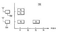
도7은 서로 비대칭적인 간섭 상태에 있는 두 개의 WTRU를 도시한 도면.7 illustrates two WTRUs in an asymmetric interference state with each other.
이후, "무선 송수신 장치(WTRU)"라는 용어는 사용자 장치, 이동국, 고정 또는 이동 가입자 장치, 페이저 또는 기타 무선 환경에서 작동 가능한 장치를 포함하나 이에 제한되지는 않는다. 이후 용어 "기지국"이 언급될 때, 이는 노드-B, 사이트 제어기, 접속 지점 또는 기타 무선 통신 환경에서의 인터페이스 장치를 포함하지만 이에 제한되지는 않는다.The term " WTRU " hereafter includes, but is not limited to, a user device, mobile station, fixed or mobile subscriber device, pager or other device operable in a wireless environment. When the term “base station” is referred to hereafter, it includes, but is not limited to, an interface device in a Node-B, site controller, access point or other wireless communication environment.
비록 이하의 실시예가 WTRU와 WTRU 간의 간섭이라는 용어로 기술되어 있지만, 본원에서 공개된 기술은 또한 기지국과 기지국 간의 간섭 시나리오에 대해서도 적용될 수 있다. 예를 들어, 제1 AP의 다운링크와 제2 AP의 업링크간에 간섭이 발생할 때, 접속 지점(AP) 대 접속지점 간섭은 본원에서 공개된 기술을 이용하여 완화될 수 있다.Although the following embodiments are described in terms of interference between WTRUs and WTRUs, the techniques disclosed herein may also apply to interference scenarios between base stations. For example, when interference occurs between the downlink of the first AP and the uplink of the second AP, access point (AP) to access point interference may be mitigated using the techniques disclosed herein.
추가로 이후 빔이 주로 2차원에서 기술되었지만, 일부 빔은 상이한 방위각으로 수직으로 이동된다.In addition, although the beam has been described mainly in two dimensions, some beams are moved vertically at different azimuth angles.
양호한 제1 실시예에서, 적응성 안테나, 예를 들어 적응성 안테나 어레이는 이웃한 WTRU로부터의 간섭을 막기 위해서 WTRU 수신기를 사용한다. (대략 무-지향성 안테나 패턴을 가지는(도1 참고))일반적인 WTRU가 사용하는 단일 안테나와 다르게, 적응성 안테나 어레이는 현재의 라디오 상태에 적응하기 위해 실시간으로 동적 으로 조절되는 안테나 패턴을 생성할 수 있다. WTRU에서 사용되어, 안테나 어레이는 연속적으로 무선 통신 주파수(RF) 환경을 감시하며, 자세하게는 서비스를 제공하는 기지국으로부터 수신된 신호 및 기타 수신된 간섭을 감시한다.In a first preferred embodiment, an adaptive antenna, for example an adaptive antenna array, uses a WTRU receiver to prevent interference from neighboring WTRUs. Unlike the single antenna used by a typical WTRU (with an approximately omni-directional antenna pattern (see Figure 1)), an adaptive antenna array can generate an antenna pattern that is dynamically adjusted in real time to adapt to the current radio conditions. . Used in the WTRU, the antenna array continuously monitors the radio communication frequency (RF) environment and specifically monitors signals received from the serving base station and other received interference.
또한 본 WTRU의 신호 처리기가 각각의 안테나에서 수신 신호가 증가함에 따른 안테나 가중치를 계산하기 위해 사용된다. 상기 안테나 가중치는 WTRU의 빔 패턴을 형성하는 역할을 한다. 안테나 어레이가 계속 무선 통신의 변화를 감시하기 때문에, 신호 처리 장치는 WTRU의 안테나 패턴을 최적화하기 위해 계속 안테나 가중치를 다시 계산한다. 안테나 가중치는 1) 신호대 잡음 비(SNR) 또는 신호대 잡음 플러스 간섭 비(SNIR)를 최대화하거나; 2)수신 간섭 신호를 최소화하거나; 3)적절히 일정하게 수신 신호 레벨을 유지하는 동안 수신 잡음을 최소화하기 위해서 계산된다. 이후, 상기 3가지 최적화 대안은 "세가지 최적화 대안"으로 총칭되어 나타낼 것이다. 상기 기술한 WTRU의 수신부의 일 실시예는 도2에 도시되었다. The signal processor of the present WTRU is also used to calculate antenna weights as the received signal increases at each antenna. The antenna weight serves to form the beam pattern of the WTRU. Since the antenna array continues to monitor changes in wireless communication, the signal processing apparatus continues to recalculate antenna weights to optimize the antenna pattern of the WTRU. Antenna weights may be: 1) maximize signal to noise ratio (SNR) or signal to noise plus interference ratio (SNIR); 2) minimize incoming interference signals; 3) Calculated to minimize received noise while keeping the received signal level reasonably constant. The three optimization alternatives will hereinafter be referred to collectively as the "three optimization alternatives." One embodiment of the receiver of the above-described WTRU is shown in FIG.
도2의 안테나(


상기 가중치(w1, w2,...,wn)를 조절하는 임의의 방법이 상술한 3가지 최적화 대안을 달성하기 위해서 사용된다. 예를 들어, 적절히 양자화된 가중치 집합은 적절한 집합이 발견될 때까지 순차적으로 시도된다. 신호 처리기(220)는 결정된 안테나 가중치(w1, w2,...,wn)를 신호 가중 장치(230)로 전송한다. 신호 가중 장치(230)에서, 최초에 수신된 신호(


이러한 방식으로 적응성 안테나를 사용하여 WTRU는 상술한 3가지 최적화 대안을 달성하기 위한 방향성 빔 패턴을 형성할 수 있다. 상기의 방향성 빔 패턴을 생성함에 있어서, 적응성 안테나는 또한 널(null)을 생성한다. 널은 단지 낮은 안테나 이득을 갖는 방향에 불과하다. 도3은 이러한 개념을 도시한다. WTRU(302)는 빔 패턴(320)이 기지국(330)을 향하도록 하는 안테나 어레이(310)를 구비하는 것으로 도시되었다. 안테나 어레이(310)는 또한 널(321)이 이웃한 WTRU 대 WTRU(MS-MS) 간섭의 발생원에 해당하는 WTRU(304)를 대략 향하게 한다. 본 실시예에서, 널 빔(321)은 WTRU(304)로부터 업링크(UL) 방향으로 전송된 신호에 의해서 발생하는 간섭을 없애거나 최소화하는 효과를 가진다.Using an adaptive antenna in this manner, the WTRU may form a directional beam pattern to achieve the three optimization alternatives described above. In generating the directional beam pattern, the adaptive antenna also generates null. Null is just the direction with low antenna gain. 3 illustrates this concept. The
양호한 제2 실시예에서, 적응성 안테나 어레이는 상술한 3가지 최적화 대안 중 하나를 달성하기 위해 사용된다. 그 후 WTRU는 기지국에 전송하기 위해서 선택된 가중치로부터 획득된 안테나 가중치를 사용한다. 선택된 전송 가중치는 수신기를 위한 본질적인 위치 및 생성된 빔의 모양이 유지되는 상태에서 선택되어야 한다. 예를 들어, 획득된 전송 안테나 가중치는 신호를 수신하기 위해 선택된 안테나 가중치와 동일하다.In a second preferred embodiment, an adaptive antenna array is used to achieve one of the three optimization alternatives described above. The WTRU then uses the antenna weight obtained from the selected weight for transmission to the base station. The selected transmission weight should be chosen with the inherent position for the receiver and the shape of the generated beam maintained. For example, the obtained transmit antenna weight is equal to the antenna weight selected for receiving the signal.
상술한 바처럼 획득된 안테나 가중치를 사용하여 전송하는 것은 전송하는 WTRU가 이웃한 WTRU와 상호 간섭 상태에 있을 때 특히 유용하다. WTRU는 제1 WTRU의 UL 주파수가 제2 WTRU의 DL 주파수와 유사하거나 동일하고 제1 WTRU의 DL 주파수가 제2 WTRU의 UL 주파수와 유사하거나 동일할 때 상호 간섭 상태에 있다고 설명된다. 설명을 위해 도4는 서로 상호 간섭 상태에 있는 두 개의 WTRU(402, 404)를 도시한다. WTRU(404)의 UL 주파수(f1)은 WTRU(402)의 DL 주파수(f1')와 매우 유사하다. 유사하게 WTRU(402)의 UL 주파수(f3)는 WTRU(404)의 DL 주파수(f3')와 매우 유사하다. 그러므로 WTRU(402, 404)는 어느 한쪽이 전송 중일 때 WTRU 양자가 MS-MS 간섭을 경험하는 상호 간섭 상태에 있다.Transmitting using the antenna weight obtained as described above is particularly useful when the transmitting WTRUs are in mutual interference with neighboring WTRUs. The WTRU is described to be in mutual interference when the UL frequency of the first WTRU is similar or equal to the DL frequency of the second WTRU and the DL frequency of the first WTRU is similar or equal to the UL frequency of the second WTRU. 4 illustrates two WTRUs 402 and 404 in mutual interference with each other. The UL frequency f1 of the
시분할 복신(TDD)을 사용하는 통신 시스템에서, WTRU는 동일한 주파수로 신호를 전송하고 수신한다. 정렬되지 않으면, 상기 WTRU는 상호 간섭을 경험하게 된다. 예를 들어, 두 개의 TDD WTRU가 상이한 시간 슬롯 또는 주파수로 정렬되고 그들 각각의 주파수가 유사하거나, 그들의 타이밍이 적절이 정렬되지 않거나, 둘 모두에 해당하는 경우 상기 WTRU는 상호 간섭을 경험하게 된다.In a communication system using time division duplex (TDD), the WTRU transmits and receives signals at the same frequency. If not aligned, the WTRUs will experience mutual interference. For example, if two TDD WTRUs are aligned in different time slots or frequencies and their respective frequencies are similar, or their timing is not properly aligned, or both, the WTRUs will experience mutual interference.
양호한 제1 실시예에서 상술한 것과 동일한 방식으로, 본 실시예에 따른 WTRU는 상술한 3가지 최적화 대안 중 하나에 따라서 요구되는 신호의 신호 품질을 최적화하기 위해 안테나 가중치를 사용한다. 그러나 본 실시예에서, WTRU는 UL 방향으로 전송하기 위해서 선택된 수신 안테나 가중치로부터 안테나 가중치를 획득한다. 방향성 전송 빔을 형성하기 위해 상기의 획득된 안테나 가중치를 사용함으로 써, 인접한 WTRU를 향하는 에너지는 이웃한 WTRU가 MS-MS 간섭을 경험하지 않도록 적합하게 감소할 것이다.In the same manner as described above in the first preferred embodiment, the WTRU according to this embodiment uses antenna weights to optimize the signal quality of the required signal according to one of the three optimization alternatives described above. However, in this embodiment, the WTRU obtains antenna weights from the received antenna weights selected for transmission in the UL direction. By using the obtained antenna weights to form a directional transmission beam, the energy towards the neighboring WTRUs will be suitably reduced so that neighboring WTRUs do not experience MS-MS interference.
양호한 세 번째 실시예에서, 전환-빔/전환 안테나 어레이(SBSA)가 인접한 WTRU로부터의 간섭을 막기 위해서 WTRU 수신기에서 사용된다. SBSA는 정해진 시간에서 사용되도록 선택된 서브셋에 해당하는 다중 예정 빔을 형성하거나, 예정된 빔 위치의 큰 집합에서 벗어난 빔 집합을 형성한다. 상기 형성된 빔 패턴 중 하나는 무-지향성 빔 패턴이라는 것을 기억해야 한다. 예정된 빔 패턴의 실시예는 도5에 도시되었다. 12개의 예정된 안테나 빔(520, 522)을 구비한 전환-빔/전환 안테나 어레이(510)가 도시되었다. 가장 높은 신호 품질을 제공하는 빔은 하이라이트 되어 도시되었고, 아마도 기지국(도시 하지 않음)방향으로 위치할 것이다.In a third preferred embodiment, a switch-beam / switch antenna array (SBSA) is used at the WTRU receiver to prevent interference from adjacent WTRUs. The SBSA forms multiple predetermined beams corresponding to the subset selected for use at a given time, or forms a beam set that deviates from a large set of predetermined beam positions. It should be remembered that one of the formed beam patterns is an omni-directional beam pattern. An embodiment of the predetermined beam pattern is shown in FIG. A switch-beam /
도5는 단순히 SBSA 개념의 예로서 제공된 것임을 이해하여야한다. 본 발명의 실시예에 따른 SBSA 시스템은 단지 2개의 빔을 가질 수도 있으며, 어쩌면 무-지향성 응답을 갖는 것을 포함할 수 있다. SBSA에 의해서 생성된 안테나 빔의 수보다 적고 더 크기가 큰 빔 각각이 필요할 수 있다. 빔의 폭 및 빔의 수는 장치의 종류와 크기를 고려하여 결정된다.It should be understood that Figure 5 is provided merely as an example of the SBSA concept. An SBSA system according to an embodiment of the present invention may have only two beams, and maybe include having an omni-directional response. Each smaller and larger beam may be needed than the number of antenna beams generated by the SBSA. The width of the beam and the number of beams are determined in consideration of the type and size of the device.
본 실시에에 따라서, 신호는 각각의 WTRU의 예정된 빔에서 측정된다. 상기 빔 중 하나는 1) 수신된 신호의 신호대 잡음 플러스 간섭 비(SNIR)를 최대화하거나; 2) 이웃한 WTRU로부터 수신된 에너지를 최소화하거나; 3) 충분한 요구되는 신호 레벨을 유지하면서 이웃한 WTRU로부터 수신된 에너지를 최소화하도록 선택된다. 그 후 전환 기능은 다운링크 방향에서 원하는 신호를 수신하기 위해서 상기 고정된 빔 패턴 중 선택된 빔으로 변경한다. 몇몇의 경우, 선택된 빔은 무 지향성 빔이다. 이웃한 WTRU로부터 수신되는 간섭 에너지의 계속된 감소는 WTRU의 신호 환경에 반응하는 예정된 빔 패턴 사이에서의 빈번한 전환에 의해서 유지된다. 이러한 개념은 도6에 도시되었다.According to this embodiment, the signal is measured at the predetermined beam of each WTRU. One of the beams may be: 1) maximize the signal-to-noise plus interference ratio (SNIR) of the received signal; 2) minimize energy received from neighboring WTRUs; 3) is selected to minimize energy received from neighboring WTRUs while maintaining sufficient required signal levels. The switching function then changes to a selected one of the fixed beam patterns to receive the desired signal in the downlink direction. In some cases, the selected beam is a non-directional beam. The continued reduction in interference energy received from neighboring WTRUs is maintained by frequent switching between predetermined beam patterns in response to the WTRU's signal environment. This concept is shown in FIG.
WTRU(602)의 안테나 어레이(601)는 다중 예정 빔(620, 622)을 형성한다. 능동적이며 기지국(630)을 향하는 빔(622)은 하이라이트 되어 도시되었다. 따라서, 이웃한 WTRU(604)를 향하는 이득은 감소하게 된다.The antenna array 601 of the
상술한 방식으로 전환 빔 안테나를 사용하는 것은 WTRU가 다수의 예정된 안테나 빔에서 안테나 빔을 선택하는 것을 가능하게 한다. 상기 빔 중에서 빔을 선택하는 것에서, 이웃한 WTRU로부터 수신된 간섭은 도6에 도시한 바처럼 감소한다. 상기 실시에 대한 추가적인 이점은 대역 내부 간섭 및 대역 외부 간섭을 동시에 최소화시킨다는 것이다. Using a switched beam antenna in the manner described above enables the WTRU to select an antenna beam from multiple predetermined antenna beams. In selecting a beam from among the beams, interference received from neighboring WTRUs is reduced as shown in FIG. An additional advantage to this implementation is that it minimizes both in-band interference and out-of-band interference at the same time.
네 번째 실시예에서, 전환 빔 안테나 어레이는 이웃한 WTRU에 의한 MS-MS 간섭, 특히 WTRU가 상호 간섭 상태에 있는 경우에 MS-MS 간섭을 최소화하기 위해 WTRU에서 사용된다. 상술한 바와 같이, 예를 들어 제1 WTRU의 DL 주파수가 제2 WTRU의 UL 주파수와 유사하고 제2 WTRU의 DL 주파수가 제1 WTRU의 UL 주파수와 유사한 경우(도4 참고), WTRU는 상호 간섭 상태에 있다. 적절한 배열이 없는 경우, TDD 통신 시스템에서 WTRU는 상호 간섭을 경험할 수 있다.In a fourth embodiment, a switched beam antenna array is used in the WTRU to minimize MS-MS interference by neighboring WTRUs, in particular when the WTRUs are in mutual interference. As described above, for example, if the DL frequency of the first WTRU is similar to the UL frequency of the second WTRU and the DL frequency of the second WTRU is similar to the UL frequency of the first WTRU (see FIG. 4), the WTRUs may interfere with each other Is in a state. If there is no proper arrangement, in a TDD communication system the WTRU may experience mutual interference.
양호한 3 번째 실시예에서 기술 한 것과 동일한 방식으로, WTRU는 SNIR을 최대화하거나, 이웃한 WTRU로부터 수신되는 에너지를 최소화하거나 현저하게 필요한 신호 레벨을 유지하면서 이웃한 WTRU로부터 수신되는 에너지를 최소화하기 위해서 예정되고 고정된 다수의 안테나 빔 사이에서 선택적으로 교환한다. 그러나 본 실시예에서는, WTRU는 UL 방향으로 전송하기 위해 동일한 선택된 안테나 빔을 사용한다. 선택된 빔은 불필요한 발생원으로부터의 간섭 에너지를 최소화하기 때문에, 이러한 동일한 빔 상에서의 전송은 이웃한 발생원을 향하는 불필요한 에너지의 전송을 최소화한다. 따라서, 선택된 빔 방향으로 전송함으로써, 이웃한 WTRU를 향하는 간섭은 최소화된다.In the same manner as described in the third preferred embodiment, the WTRU is intended to maximize the SNIR, minimize the energy received from the neighboring WTRUs, or minimize the energy received from the neighboring WTRUs while maintaining a significantly required signal level. And selectively exchange between a plurality of fixed antenna beams. However, in this embodiment, the WTRU uses the same selected antenna beam to transmit in the UL direction. Since the selected beam minimizes the interference energy from unnecessary sources, the transmission on this same beam minimizes the transmission of unnecessary energy towards neighboring sources. Thus, by transmitting in the selected beam direction, interference towards neighboring WTRUs is minimized.
다섯 번째 실시예에서, 스마트 안테나 어레이가 이웃한 WTRU에 의해, 특히 WTRU가 비대칭 간섭 상태에 있는 경우에 경험되는 MS-MS 간섭을 최소화하기 위해 WTRU에서 사용된다. 이후로 "스마트 안테나"라는 용어는 적응성 안테나 어레이 도는 전환 빔/전환 안테나 어레이를 설명하기 위해서 사용된다. 본 실시예의 목적을 위해서, WTRU는 제1 WTRU이 스펙트럼이 인접한 제2 WTRU의 DL 수신과 간섭을 발생시키는 경우 비대칭 간섭 상태에 있다. 그러나 제2 WTRU의 UL 전송은 제1 WTRU의 DL 수신과 간섭이 발생하지 않는다. 이러한 개념은 도7에 도시되었다.In a fifth embodiment, a smart antenna array is used in a WTRU to minimize MS-MS interference experienced by neighboring WTRUs, especially when the WTRU is in an asymmetric interference state. The term "smart antenna" is subsequently used to describe an adaptive antenna array or switching beam / switching antenna array. For the purposes of this embodiment, the WTRU is in an asymmetric interference state when the first WTRU interferes with the DL reception of a second WTRU in adjacent spectrum. However, the UL transmission of the second WTRU does not interfere with the DL reception of the first WTRU. This concept is shown in FIG.
통신 시스템(700)은 TDD WTRU(702)가 UL 주파수(f1)를 갖는 것으로 도시되었다. FDD 장치인 WTRU(704)는 WTRU(702)와 스펙트럼이 인접한 DL 수신 주파수를 갖는 것으로 도시하였다. 그 결과, TDD 장치(702)는 스펙트럼 상으로 인접한 FDD 장치(704)의 DL 수신과 간섭을 발생시킨다. 그러나 이러한 간섭은 FDD 장치(704)의 UL 전송 주파수(f3)가 TDD 장치(702)의 DL 주파수(f1)와 스펙트럼 상으로 떨어져 있기 때문에 비대칭적이다. WTRU(702)는 TDD 장치이기 때문에, 그것의 UL 및 DL 주 파수는 동일하다는 것을 기억해야 한다.The
도7에서 도시한 바처럼, TDD 장치(702) 같은 WTRU는 간섭이 발생하고 있음을 인식하지 못하면서 비대칭적으로 이웃한 WTRU와 간섭을 발생시킬 수 있다. 이러한 인식의 결여는 간섭을 일으키는 WTRU의 수신 주파수가 스펙트럼 상으로 희생 WTRU의 UL 주파수와 떨어져 있기 때문에 발생한다. 본 실시예는 간섭을 일으키는 WTRU에 추가적인 정보를 제공함으로써 상기와 같은 비대칭 간섭을 최소화시키는 방안을 제공한다. (예를 들어 도7의 TDD WTRU와 같은) 비대칭적인 간섭을 발생시키는 WTRU에는 신호 환경에서의 스펙트럼 배열이 통보된다. 자세하게는, DL 주파수가 UL 주파수와 인접한 WTRU의 UL 주파수가 통보된다. 이러한 정보는 간섭을 발생의 원인이 될 수 있는 다른 WTRU의 존재를 간섭을 발생시키는 WTRU에 경고한다. 그 후 간섭을 발생시키는 WTRU는 상기 WTRU의 실제 위치를 결정하기 위해서 UL 주파수를 스캔한다. 간섭을 발생시키는 WTRU는 예를 들어 높은 에너지 신호를 탐색하는 방식으로 상기 WTRU의 위치를 결정한다. UL 방향에서 충분히 높은 에너지 레벨은 WTRU가 가까이에 있으며 간섭이 발생할 수 있다는 것을 의미한다. 그러므로 간섭을 발생시키는 WTRU는 인접한 WTRU와의 간섭을 최소화하기 위해서 예를 들어 본원에 기술한 실시예 중 임의의 것에서 사용하는 UL 전송 방향을 조정한다.As shown in FIG. 7, a WTRU such as
대안으로서, WTRU의 신호환경에서 스펙트럼 배열에 대해 간섭을 일으키는 WTRU에 통보하고 이에 따라 WTRU 탐색을 제한하는 것 대신에, WTRU는 모든 가능한 주파수를 탐색할 수 있다. 비록 다양한 실시예의 구성요소가 분리된 구성요소로서 설명되었지만, 주문형 반도체(ASIC), 다중 IC, 분리 구성요소 또는 분리 구성요소 와 IC의 조합 같은 신호 집적회로(IC)일 수도 있다.Alternatively, instead of notifying the WTRUs that interfere with the spectral arrangement in the WTRU's signal environment and thereby limiting the WTRU search, the WTRU may search for all possible frequencies. Although the components of the various embodiments have been described as discrete components, they may also be signal integrated circuits (ICs), such as application specific semiconductors (ASICs), multiple ICs, discrete components or a combination of discrete components and ICs.
유사하게, 본 발명의 특징 및 구성요소가 특정 조합의 양호한 실시예로 기술되었지만, (양호한 실시예의 다른 특징 및 구성요소 없이) 각각의 특징 또는 구성요소는 단독으로 사용될 수 있거나 다른 본 발명의 다른 특징 및 구성요소와 다양하게 조합되거나 조합되지 않고 사용될 수 있다.Similarly, while the features and components of the present invention have been described in the preferred embodiments of a particular combination, each feature or component (without other features and components of the preferred embodiments) may be used alone or in other features of the present invention. And various combinations with or without components.
Claims (32)
Translated fromKoreanApplications Claiming Priority (4)
| Application Number | Priority Date | Filing Date | Title |
|---|---|---|---|
| US55796704P | 2004-03-31 | 2004-03-31 | |
| US60/557,967 | 2004-03-31 | ||
| US11/025,252 | 2004-12-29 | ||
| US11/025,252US7630688B2 (en) | 2004-03-31 | 2004-12-29 | Mitigation of wireless transmit/receive unit (WTRU) to WTRU interference using multiple antennas or beams |
Related Child Applications (1)
| Application Number | Title | Priority Date | Filing Date |
|---|---|---|---|
| KR1020067022591ADivisionKR20060130770A (en) | 2004-03-31 | 2005-03-10 | Apparatus and method for mitigating interference between radio transceivers (BTR) using multiple antennas or beams |
Publications (1)
| Publication Number | Publication Date |
|---|---|
| KR20060131993Atrue KR20060131993A (en) | 2006-12-20 |
Family
ID=35055056
Family Applications (3)
| Application Number | Title | Priority Date | Filing Date |
|---|---|---|---|
| KR1020067021409ACeasedKR20060131993A (en) | 2004-03-31 | 2005-03-10 | Apparatus and method for mitigating interference between radio transceivers (BTR) using multiple antennas or beams |
| KR1020067022591ACeasedKR20060130770A (en) | 2004-03-31 | 2005-03-10 | Apparatus and method for mitigating interference between radio transceivers (BTR) using multiple antennas or beams |
| KR1020107008981ACeasedKR20100054876A (en) | 2004-03-31 | 2005-03-10 | Mitigation of wireless transmit/receive unit (wtru) to wtru interference using multiple antennas or beams |
Family Applications After (2)
| Application Number | Title | Priority Date | Filing Date |
|---|---|---|---|
| KR1020067022591ACeasedKR20060130770A (en) | 2004-03-31 | 2005-03-10 | Apparatus and method for mitigating interference between radio transceivers (BTR) using multiple antennas or beams |
| KR1020107008981ACeasedKR20100054876A (en) | 2004-03-31 | 2005-03-10 | Mitigation of wireless transmit/receive unit (wtru) to wtru interference using multiple antennas or beams |
Country Status (10)
| Country | Link |
|---|---|
| US (2) | US7630688B2 (en) |
| EP (2) | EP1738564A4 (en) |
| JP (6) | JP2007532059A (en) |
| KR (3) | KR20060131993A (en) |
| CN (1) | CN101124803B (en) |
| AR (2) | AR048352A1 (en) |
| CA (1) | CA2561713C (en) |
| NO (1) | NO340372B1 (en) |
| TW (5) | TWI260933B (en) |
| WO (1) | WO2005104503A2 (en) |
Families Citing this family (41)
| Publication number | Priority date | Publication date | Assignee | Title |
|---|---|---|---|---|
| US7630688B2 (en)* | 2004-03-31 | 2009-12-08 | Interdigital Technology Corporation | Mitigation of wireless transmit/receive unit (WTRU) to WTRU interference using multiple antennas or beams |
| KR100706620B1 (en)* | 2005-05-17 | 2007-04-11 | 한국전자통신연구원 | Beam Selection Method for Initial Synchronization Using Switch Beam |
| US20080056201A1 (en)* | 2006-03-22 | 2008-03-06 | Broadcom Corporation, A California Corporation | Interference parameter reporting from client devices to access point for use in modifying wireless operations |
| EP1843485B1 (en) | 2006-03-30 | 2016-06-08 | Sony Deutschland Gmbh | Multiple-input multiple-output (MIMO) spatial multiplexing system with dynamic antenna beam combination selection capability |
| EP2022180B1 (en)* | 2006-05-29 | 2016-02-03 | Telefonaktiebolaget LM Ericsson (publ) | Channel quality prediction in hsdpa systems |
| JP4972370B2 (en)* | 2006-09-21 | 2012-07-11 | 京セラ株式会社 | Wireless communication apparatus and wireless communication method |
| US20080102768A1 (en)* | 2006-10-25 | 2008-05-01 | Navini Networks, Inc. | Method for Obtaining a Covariance Matrix of a Transmitting Channel in a Wireless Network |
| US7995973B2 (en)* | 2008-12-19 | 2011-08-09 | Telefonaktiebolaget Lm Ericsson (Publ) | Own transmitter interference tolerant transceiver and receiving methods |
| US8855580B2 (en)* | 2008-06-27 | 2014-10-07 | Telefonaktiebolaget L M Ericsson (Publ) | Methods and apparatus for reducing own-transmitter interference in low-IF and zero-IF receivers |
| CN102187725B (en)* | 2008-10-20 | 2014-12-31 | 交互数字专利控股公司 | Carrier aggregation |
| KR101303709B1 (en)* | 2008-10-31 | 2013-09-03 | 인터디지탈 패튼 홀딩스, 인크 | Method and apparatus for utilizing multiple carriers in high speed packet access communications |
| US8385281B2 (en) | 2009-01-30 | 2013-02-26 | Interdigital Patent Holdings, Inc. | Method and apparatus for component carrier aggregation in wireless communications |
| US8023915B2 (en)* | 2009-03-30 | 2011-09-20 | Mitsubishi Electric Research Laboratories, Inc. | Beamforming in wireless vehicular networks |
| PH12012500961A1 (en)* | 2009-11-30 | 2021-06-23 | Ericsson Telefon Ab L M | Interference mitigation in downlink signal communication to a mobile terminal |
| EP2517376B1 (en)* | 2009-12-21 | 2016-11-02 | Telefonaktiebolaget LM Ericsson (publ) | Method for suppressing opposite direction interference |
| US20140160968A1 (en)* | 2011-07-04 | 2014-06-12 | Telefonaktiebolaget L M Ericsson (Publ) | Enhanced Use of Frequency Spectrum in a Wireless Communication Network |
| KR101800221B1 (en) | 2011-08-11 | 2017-11-22 | 삼성전자주식회사 | Method and apparatus for beam tracking in wireless communication system |
| KR101839808B1 (en)* | 2011-08-24 | 2018-04-26 | 삼성전자주식회사 | Mobile Terminal and Communication Method, Base Station Control Apparatus and Method, and Multi-Point Transmission System and Method using the Same |
| EP2769485A1 (en)* | 2011-10-19 | 2014-08-27 | Marvell World Trade Ltd. | Systems and methods for suppressing interference in a signal received by a device having two or more antennas |
| US9054765B2 (en) | 2011-10-20 | 2015-06-09 | Marvell World Trade Ltd. | Systems and methods for suppressing interference in a wireless communication system |
| WO2014003499A1 (en)* | 2012-06-29 | 2014-01-03 | Samsung Electronics Co., Ltd. | Method and apparatus for beamforming |
| CN104335508B (en)* | 2012-07-02 | 2017-09-12 | 英特尔公司 | Launch simultaneously and receive |
| JP2014114006A (en)* | 2012-11-16 | 2014-06-26 | Tokai Rika Co Ltd | Tire position determination device |
| CN103856306B (en)* | 2012-12-05 | 2017-10-17 | 华为技术有限公司 | Handle the method and device of interference |
| US9071474B1 (en) | 2013-07-25 | 2015-06-30 | Marvell International Ltd. | Systems and methods for suppressing interference in a wireless communication system |
| US9806827B2 (en)* | 2013-09-13 | 2017-10-31 | Samsung Electronics Co., Ltd. | Computing system with interference cancellation mechanism and method of operation thereof |
| EP2930994B1 (en)* | 2014-04-07 | 2016-05-18 | Alcatel Lucent | Mitigating UL-to-DL interference |
| US9960828B2 (en)* | 2014-05-08 | 2018-05-01 | Telefonaktiebolaget Lm Ericsson (Publ) | Beam forming using an antenna arrangement |
| US9578644B2 (en) | 2014-09-26 | 2017-02-21 | Mediatek Inc. | Beam misalignment detection for wireless communication system with beamforming |
| CN107251618B (en)* | 2015-01-16 | 2021-05-14 | 梁平 | Beamforming in a multi-user multiple-input multiple-output wireless communication system with repeaters |
| US9806781B2 (en)* | 2015-04-29 | 2017-10-31 | Samsung Electronics Co., Ltd. | Codebook design and structure for advanced wireless communication systems |
| JP2017059933A (en)* | 2015-09-15 | 2017-03-23 | 日本電気株式会社 | Communication system, base station, and antenna control method |
| US20170303328A1 (en)* | 2016-04-15 | 2017-10-19 | Intel IP Corporation | Antenna weight vector group identification for wireless communication |
| US10833832B2 (en) | 2016-06-22 | 2020-11-10 | Intel Corporation | Communication device and a method for full duplex scheduling |
| US10333599B2 (en)* | 2016-09-13 | 2019-06-25 | Corning Optical Communications LLC | Antenna array beamforming in a remote unit(s) in a wireless distribution system (WDS) |
| KR102470863B1 (en) | 2018-03-09 | 2022-11-28 | 삼성전자주식회사 | Method and appatus of interference measurement |
| CN112205043A (en)* | 2018-05-30 | 2021-01-08 | 株式会社Ntt都科摩 | communication device |
| KR102018254B1 (en)* | 2018-09-10 | 2019-09-04 | 에스케이텔레콤 주식회사 | Signal transmitting apparatus and signal transmitting method |
| CN114008857B (en)* | 2020-03-30 | 2023-10-10 | 华为技术有限公司 | Antenna system, control method, processor and image pickup system |
| WO2022137493A1 (en)* | 2020-12-25 | 2022-06-30 | 日本電信電話株式会社 | Signal processing device, wireless communication system, and signal processing method |
| WO2024077211A1 (en)* | 2022-10-07 | 2024-04-11 | Interdigital Patent Holdings, Inc. | Methods, procedures, and devices to improve beam resilience in multi-antenna systems with hybrid beamforming |
Family Cites Families (48)
| Publication number | Priority date | Publication date | Assignee | Title |
|---|---|---|---|---|
| JP2911090B2 (en)* | 1993-09-29 | 1999-06-23 | エヌ・ティ・ティ移動通信網株式会社 | Mobile communication base station device and mobile station device |
| US5619503A (en)* | 1994-01-11 | 1997-04-08 | Ericsson Inc. | Cellular/satellite communications system with improved frequency re-use |
| JP3497672B2 (en)* | 1996-09-18 | 2004-02-16 | 株式会社東芝 | Adaptive antenna and multi-carrier wireless communication system |
| JP3464606B2 (en)* | 1998-03-31 | 2003-11-10 | 松下電器産業株式会社 | Wireless communication device and wireless communication method |
| EP0948082A1 (en)* | 1998-04-03 | 1999-10-06 | Lucent Technologies Inc. | Adaptive antenna |
| US6188915B1 (en)* | 1998-05-19 | 2001-02-13 | Harris Corporation | Bootstrapped, piecewise-asymptotic directivity pattern control mechanism setting weighting coefficients of phased array antenna |
| KR100272565B1 (en)* | 1998-06-16 | 2000-11-15 | 서평원 | Method for allocating Optimal Orthogonal Code of Reverse Link |
| US6229486B1 (en)* | 1998-09-10 | 2001-05-08 | David James Krile | Subscriber based smart antenna |
| US6314305B1 (en)* | 1998-12-10 | 2001-11-06 | Lucent Technologies Inc. | Transmitter/receiver for combined adaptive array processing and fixed beam switching |
| GB2349045A (en) | 1999-04-16 | 2000-10-18 | Fujitsu Ltd | Base station transmission beam pattern forming; interference reduction |
| EP1172956B1 (en)* | 1999-04-22 | 2008-08-13 | Nippon Telegraph and Telephone Corporation | OFDM packet communication receiver |
| US6661832B1 (en)* | 1999-05-11 | 2003-12-09 | Qualcomm Incorporated | System and method for providing an accurate estimation of received signal interference for use in wireless communications systems |
| JP3387459B2 (en)* | 1999-09-30 | 2003-03-17 | 日本電気株式会社 | Radio monitoring system and radio monitoring method |
| CN1336046A (en)* | 1999-11-10 | 2002-02-13 | 三菱电机株式会社 | Adaptive arry communication system and receiver |
| US7046678B2 (en)* | 2000-02-18 | 2006-05-16 | At & T Corp. | Channel efficiency based packet scheduling for interactive data in cellular networks |
| JP2001237756A (en)* | 2000-02-25 | 2001-08-31 | Matsushita Electric Ind Co Ltd | Array antenna wireless communication device and array antenna wireless communication method |
| US6940845B2 (en)* | 2000-03-23 | 2005-09-06 | At & T, Corp. | Asymmetric measurement-based dynamic packet assignment system and method for wireless data services |
| WO2002007342A1 (en)* | 2000-07-14 | 2002-01-24 | Sanyo Electric Co., Ltd. | Mobile communication terminal, communication method, and program |
| EP1309104B1 (en)* | 2000-07-14 | 2011-06-08 | Sanyo Electric Co., Ltd. | Calibration device, adaptive array device, calibration method, program recording medium and program |
| US6400315B1 (en)* | 2000-07-20 | 2002-06-04 | The Boeing Company | Control system for electronically scanned phased array antennas with a mechanically steered axis |
| DE60008930T2 (en)* | 2000-12-04 | 2005-01-27 | Mitsubishi Denki K.K. | SYNTHESIS RECEIVING METHOD AND SYNTHESIS RECEIVER |
| JP4282227B2 (en)* | 2000-12-28 | 2009-06-17 | 日本電気株式会社 | Noise removal method and apparatus |
| US20020146044A1 (en)* | 2001-04-09 | 2002-10-10 | Riaz Esmailzadeh | Hybrid single/multiuser interference reduction detector |
| JP2002325062A (en) | 2001-04-25 | 2002-11-08 | Mitsubishi Electric Corp | Mobile communication system and mobile communication terminal device |
| US6621454B1 (en)* | 2001-05-10 | 2003-09-16 | Vectrad Networks Corporation | Adaptive beam pattern antennas system and method for interference mitigation in point to multipoint RF data transmissions |
| JP2003018074A (en)* | 2001-06-29 | 2003-01-17 | Toshiba Corp | Radio base station and beam control method |
| EP1667341B1 (en)* | 2001-07-11 | 2011-03-02 | Sony Deutschland GmbH | Method for calculating a weighting vector for an antenna array |
| US7031702B2 (en)* | 2001-09-14 | 2006-04-18 | Atc Technologies, Llc | Additional systems and methods for monitoring terrestrially reused satellite frequencies to reduce potential interference |
| KR100566241B1 (en)* | 2001-11-19 | 2006-03-29 | 삼성전자주식회사 | Apparatus and method for combining soft symbols in mobile communication system |
| CA2415170C (en)* | 2001-12-28 | 2008-07-15 | Ntt Docomo, Inc. | Receiver, transmitter, communication system, and method of communication |
| JP3866118B2 (en) | 2002-02-27 | 2007-01-10 | 日本電信電話株式会社 | Space division multiple access apparatus, adaptive array antenna base station, terminal and control method thereof |
| US6687492B1 (en) | 2002-03-01 | 2004-02-03 | Cognio, Inc. | System and method for antenna diversity using joint maximal ratio combining |
| JP3600218B2 (en)* | 2002-03-20 | 2004-12-15 | 三洋電機株式会社 | Wireless terminal device, transmission directivity control method, and transmission directivity control program |
| US7424268B2 (en)* | 2002-04-22 | 2008-09-09 | Cisco Technology, Inc. | System and method for management of a shared frequency band |
| CN100481988C (en) | 2002-05-13 | 2009-04-22 | 美商内数位科技公司 | Allocating resources to users in a slotted CDMA system using beams |
| KR100689399B1 (en)* | 2002-05-17 | 2007-03-08 | 삼성전자주식회사 | Apparatus and method for forward transmission beam forming of smart antenna in mobile communication system |
| EP1369954A3 (en)* | 2002-06-05 | 2004-10-20 | Fujitsu Limited | Adaptive antenna unit for mobile terminal |
| US7339981B2 (en)* | 2002-07-09 | 2008-03-04 | Arraycomm, Llc. | Shifted training sequences in a communications system |
| US7236808B2 (en) | 2002-09-09 | 2007-06-26 | Interdigital Technology Corporation | Vertical dynamic beam-forming |
| GB2393077A (en) | 2002-09-14 | 2004-03-17 | Roke Manor Research | Aligning a directional antenna towards an access point using location information |
| US7412212B2 (en)* | 2002-10-07 | 2008-08-12 | Nokia Corporation | Communication system |
| JP2004180038A (en)* | 2002-11-28 | 2004-06-24 | Nec Infrontia Corp | Wireless lan access point, wireless lan system, and method of preventing interference between wireless lan access points |
| JP3930456B2 (en) | 2003-05-29 | 2007-06-13 | 日本無線株式会社 | Array antenna communication device |
| US6879829B2 (en)* | 2003-05-16 | 2005-04-12 | Mobile Satellite Ventures, Lp | Systems and methods for handover between space based and terrestrial radioterminal communications, and for monitoring terrestrially reused satellite frequencies at a radioterminal to reduce potential interference |
| US7295831B2 (en)* | 2003-08-12 | 2007-11-13 | 3E Technologies International, Inc. | Method and system for wireless intrusion detection prevention and security management |
| US7457590B2 (en)* | 2003-12-23 | 2008-11-25 | Motorola, Inc. | Method, apparatus and system for use in the transmission of wireless communications using multiple antennas |
| US7782987B2 (en)* | 2004-03-12 | 2010-08-24 | Telefonaktiebolaget Lm Ericsson (Publ) | Method and apparatus for received signal quality estimation |
| US7630688B2 (en)* | 2004-03-31 | 2009-12-08 | Interdigital Technology Corporation | Mitigation of wireless transmit/receive unit (WTRU) to WTRU interference using multiple antennas or beams |
- 2004
- 2004-12-29USUS11/025,252patent/US7630688B2/ennot_activeExpired - Fee Related
- 2005
- 2005-03-10EPEP05725282Apatent/EP1738564A4/ennot_activeWithdrawn
- 2005-03-10TWTW094107353Apatent/TWI260933B/ennot_activeIP Right Cessation
- 2005-03-10KRKR1020067021409Apatent/KR20060131993A/ennot_activeCeased
- 2005-03-10WOPCT/US2005/008023patent/WO2005104503A2/enactiveSearch and Examination
- 2005-03-10TWTW097108405Apatent/TWI377800B/ennot_activeIP Right Cessation
- 2005-03-10TWTW101118078Apatent/TWI454081B/ennot_activeIP Right Cessation
- 2005-03-10CACA2561713Apatent/CA2561713C/ennot_activeExpired - Fee Related
- 2005-03-10TWTW103115738Apatent/TWI533638B/ennot_activeIP Right Cessation
- 2005-03-10EPEP11187124Apatent/EP2413515A3/ennot_activeWithdrawn
- 2005-03-10KRKR1020067022591Apatent/KR20060130770A/ennot_activeCeased
- 2005-03-10KRKR1020107008981Apatent/KR20100054876A/ennot_activeCeased
- 2005-03-10JPJP2007506203Apatent/JP2007532059A/enactivePending
- 2005-03-10CNCN2005800102288Apatent/CN101124803B/ennot_activeExpired - Fee Related
- 2005-03-10TWTW094131743Apatent/TWI350076B/ennot_activeIP Right Cessation
- 2005-03-30ARARP050101246Apatent/AR048352A1/enactiveIP Right Grant
- 2006
- 2006-10-25NONO20064846Apatent/NO340372B1/ennot_activeIP Right Cessation
- 2009
- 2009-01-09ARARP090100059Apatent/AR070131A2/enunknown
- 2009-02-26JPJP2009044792Apatent/JP2009135963A/enactivePending
- 2009-12-07USUS12/632,420patent/US7835700B2/ennot_activeExpired - Fee Related
- 2012
- 2012-07-30JPJP2012168710Apatent/JP2012217212A/enactivePending
- 2013
- 2013-06-03JPJP2013117217Apatent/JP6026958B2/ennot_activeExpired - Fee Related
- 2014
- 2014-12-24JPJP2014261288Apatent/JP6027085B2/ennot_activeExpired - Fee Related
- 2016
- 2016-02-29JPJP2016037907Apatent/JP6368729B2/ennot_activeExpired - Fee Related
Also Published As
Similar Documents
| Publication | Publication Date | Title |
|---|---|---|
| JP6368729B2 (en) | Mitigating Wireless Transceiver Unit-Wireless Transmitter / Receiver Unit (WTRU-WTRU) Interference Using Multiple Antennas or Multiple Beams | |
| US11134395B2 (en) | Adaptive antenna configuration | |
| KR100817620B1 (en) | Method and apparatus for adapting antenna array using received predetermined signal | |
| EP1334633B1 (en) | Mode switching in adaptive array communications systems | |
| AU2001293128A1 (en) | Mode switching in adaptive array communications systems | |
| US20030017853A1 (en) | Method and apparatus for enhancing the data transmission capacity of a wireless communication system | |
| JP2000252734A (en) | Mobile communication base station antenna device | |
| EP1407558A1 (en) | Method and apparatus for enhancing the data transmission capacity of a wireless communication system | |
| JP3832083B2 (en) | Base station antenna device | |
| MXPA06011246A (en) | Mitigation of wireless transmit/receive unit (wtru) to wtru interference using multiple antennas or beams | |
| HK1109272B (en) | Wtru and method for mitigating wtru to wtru interference in wireless communications |
Legal Events
| Date | Code | Title | Description |
|---|---|---|---|
| A201 | Request for examination | ||
| PA0105 | International application | Patent event date:20061016 Patent event code:PA01051R01D Comment text:International Patent Application | |
| PA0201 | Request for examination | ||
| A107 | Divisional application of patent | ||
| PA0104 | Divisional application for international application | Comment text:Divisional Application for International Patent Patent event code:PA01041R01D Patent event date:20061027 | |
| PG1501 | Laying open of application | ||
| E902 | Notification of reason for refusal | ||
| PE0902 | Notice of grounds for rejection | Comment text:Notification of reason for refusal Patent event date:20070920 Patent event code:PE09021S01D | |
| E601 | Decision to refuse application | ||
| PE0601 | Decision on rejection of patent | Patent event date:20080710 Comment text:Decision to Refuse Application Patent event code:PE06012S01D Patent event date:20070920 Comment text:Notification of reason for refusal Patent event code:PE06011S01I | |
| PC1202 | Submission of document of withdrawal before decision of registration | Comment text:[Withdrawal of Procedure relating to Patent, etc.] Withdrawal (Abandonment) Patent event code:PC12021R01D Patent event date:20081009 | |
| WITB | Written withdrawal of application |