KR20060123622A - Multifunctional Vibration Actuator and Handheld Device - Google Patents
Multifunctional Vibration Actuator and Handheld DeviceDownload PDFInfo
- Publication number
- KR20060123622A KR20060123622AKR1020067018674AKR20067018674AKR20060123622AKR 20060123622 AKR20060123622 AKR 20060123622AKR 1020067018674 AKR1020067018674 AKR 1020067018674AKR 20067018674 AKR20067018674 AKR 20067018674AKR 20060123622 AKR20060123622 AKR 20060123622A
- Authority
- KR
- South Korea
- Prior art keywords
- suspension
- magnetic circuit
- vibration
- housing
- circuit portion
- Prior art date
- Legal status (The legal status is an assumption and is not a legal conclusion. Google has not performed a legal analysis and makes no representation as to the accuracy of the status listed.)
- Granted
Links
Images


Classifications
- H—ELECTRICITY
- H04—ELECTRIC COMMUNICATION TECHNIQUE
- H04R—LOUDSPEAKERS, MICROPHONES, GRAMOPHONE PICK-UPS OR LIKE ACOUSTIC ELECTROMECHANICAL TRANSDUCERS; DEAF-AID SETS; PUBLIC ADDRESS SYSTEMS
- H04R9/00—Transducers of moving-coil, moving-strip, or moving-wire type
- H04R9/02—Details
- H04R9/025—Magnetic circuit
- H—ELECTRICITY
- H04—ELECTRIC COMMUNICATION TECHNIQUE
- H04R—LOUDSPEAKERS, MICROPHONES, GRAMOPHONE PICK-UPS OR LIKE ACOUSTIC ELECTROMECHANICAL TRANSDUCERS; DEAF-AID SETS; PUBLIC ADDRESS SYSTEMS
- H04R31/00—Apparatus or processes specially adapted for the manufacture of transducers or diaphragms therefor
- H04R31/003—Apparatus or processes specially adapted for the manufacture of transducers or diaphragms therefor for diaphragms or their outer suspension
- H—ELECTRICITY
- H04—ELECTRIC COMMUNICATION TECHNIQUE
- H04R—LOUDSPEAKERS, MICROPHONES, GRAMOPHONE PICK-UPS OR LIKE ACOUSTIC ELECTROMECHANICAL TRANSDUCERS; DEAF-AID SETS; PUBLIC ADDRESS SYSTEMS
- H04R2400/00—Loudspeakers
- H04R2400/03—Transducers capable of generating both sound as well as tactile vibration, e.g. as used in cellular phones
- H—ELECTRICITY
- H04—ELECTRIC COMMUNICATION TECHNIQUE
- H04R—LOUDSPEAKERS, MICROPHONES, GRAMOPHONE PICK-UPS OR LIKE ACOUSTIC ELECTROMECHANICAL TRANSDUCERS; DEAF-AID SETS; PUBLIC ADDRESS SYSTEMS
- H04R2400/00—Loudspeakers
- H04R2400/07—Suspension between moving magnetic core and housing
- H—ELECTRICITY
- H04—ELECTRIC COMMUNICATION TECHNIQUE
- H04R—LOUDSPEAKERS, MICROPHONES, GRAMOPHONE PICK-UPS OR LIKE ACOUSTIC ELECTROMECHANICAL TRANSDUCERS; DEAF-AID SETS; PUBLIC ADDRESS SYSTEMS
- H04R2499/00—Aspects covered by H04R or H04S not otherwise provided for in their subgroups
- H04R2499/10—General applications
- H04R2499/11—Transducers incorporated or for use in hand-held devices, e.g. mobile phones, PDA's, camera's
Landscapes
- Engineering & Computer Science (AREA)
- Physics & Mathematics (AREA)
- Acoustics & Sound (AREA)
- Signal Processing (AREA)
- Manufacturing & Machinery (AREA)
- Apparatuses For Generation Of Mechanical Vibrations (AREA)
- Details Of Audible-Bandwidth Transducers (AREA)
- Audible-Bandwidth Dynamoelectric Transducers Other Than Pickups (AREA)
Abstract
Translated fromKoreanDescription
Translated fromKorean본 발명은, 휴대전화나 소형 정보통신 단말 등의 휴대 단말기기에 탑재되고, 하나의 디바이스에서, 착신을 음향 혹은 진동에 의해 사용자에게 알리는 다기능형 진동 액추에이터, 및 그를 탑재한 휴대 단말기기에 관한 것이다. 상세하게는, 하우징 내에 자기 회로부와, 이 자기 회로부를 하우징에 대해 탄성적으로 지지하는 서스펜션과, 그 자기 회로부에 대향 배치되는 다이어프램과, 이 다이어프램에 설치되어 자기 회로부의 자기 공극부에 삽입되는 보이스 코일을 수용하고, 그 보이스 코일에 진동 주파수의 신호를 흘림으로써, 자기 회로부를 고정한 서스펜션의 진동이 하우징을 통해 외부로 전해지는 다기능형 진동 액추에이터에 관한 것이다.BACKGROUND OF THE
종래, 이런 종류의 다기능형 진동 액추에이터로서, 서스펜션의 중심 구멍에 자기 회로부(자기 회로)의 요크(자기 요크)를 끼워 맞춰 고정하고, 그 서스펜션의 바깥 가장자리에 같은 간격으로 설치된 복수의 돌기를 하우징(케이스)의 틀 내에 설치한 절결 단부에 끼워넣어 접착함으로써, 하우징에 대해 서스펜션의 바깥 가장자리가 고정되는 것이 있다(예를 들면, 특허문헌 1 참조). 그리고, 보이스 코일에 음성신호의 신호 전류를 흘리면, 다이어프램이 진동하여 착신음, 멜로디음, 음성, 음악 등의 소리를 발하고, 진동 주파수의 신호를 흘리면, 자기회로와 서스펜션을 포함하는 기계 진동계가 진동하고, 이 진동이 하우징을 거쳐 이 다기능형 진동 액추에이터를 탑재한 휴대 단말기기 전체로 전해지도록 되어 있다. 또한, 서스펜션(판 스프링)의 중심 구멍에 자기 회로부의 요크(하측 요크)를 끼워 맞춰 레이저 용접으로 고착하고, 그 서스펜션의 바깥 가장자리가 하우징(케이스)과 그것에 안쪽으로 끼워진 스페이서 사이에 끼워 넣어 고정한 것도 있다(예를 들면, 특허문헌 2 참조).Conventionally, this type of multifunctional vibrating actuator has been fitted with a yoke (magnetic yoke) of a magnetic circuit section (magnetic circuit) in the center hole of the suspension and fixed, and a plurality of projections provided at equal intervals on the outer edge of the suspension housing ( The outer edge of the suspension is fixed to the housing by inserting and bonding to the cutout end provided in the frame of the case) (see
특허문헌 1: 일본국 특허 공개공보 2002-191092호(제2 페이지, 도 8-11)Patent Document 1: Japanese Patent Laid-Open No. 2002-191092 (2nd page, Fig. 8-11)
특허문헌 2: 일본국 특허 공개공보 평11-7286호(제3-5 페이지, 도 2, 도 3)Patent Document 2: Japanese Patent Application Laid-Open No. 11-7286 (pages 3-5, Fig. 2, Fig. 3)
이러한 다기능형 진동 액추에이터에서, 서스펜션에 의한 진동 주파수를 정밀하게 맞추기 위해서는 서스펜션 특성과, 자기 회로부와 서스펜션으로 이루어지는 진동체의 중량을 상세하게 관리할 필요가 있다. 그런데, 서스펜션의 특성은 제조 로트마다의 재료의 약간의 차이나 치수 공차에 따라 미소하게 변화하기 쉽고, 또 자기 회로부를 구성하는 마그넷이나 요크 등의 중량도 제조 로트마다의 치수 공법에 의해 미소하게 변화한다. 그러나, 종래의 다기능형 진동 액추에이터에서는 상술한 변화 요인이 고려되지 않고, 서스펜션과 자기 회로부를 접착 또는 레이저 용착에 의해 소정 위치에 고정하였기 때문에, 이 고정 위치로부터 그 서스펜션의 하우징에 대한 고정 위치까지의 길이가 항상 일정하고, 그 조립 단계에서 서스펜션에 의한 진동 주파수를 조정하는 것이 곤란했다. 그 결과, 진동 주파수가 목표 값으로부터 어긋나면, 실제로 사용할 때에 얻어지는 가속도가 작아져, 부품 정밀도의 편 차가 원인으로 완성품의 품질을 안정시킬 수 없고, 그 때문에 제조 비용이 비싸지는 문제가 있었다.In such a multifunctional vibration actuator, in order to precisely adjust the vibration frequency by suspension, it is necessary to manage the suspension characteristic and the weight of the vibrating body which consists of a magnetic circuit part and suspension in detail. By the way, the characteristics of the suspension tend to change slightly depending on the slight difference in the material of each manufacturing lot and the dimensional tolerance, and the weight of the magnets and yokes constituting the magnetic circuit portion also changes slightly by the dimensional method for each manufacturing lot. . However, in the conventional multifunctional vibrating actuator, the above-mentioned change factor is not considered, and the suspension and the magnetic circuit part are fixed at a predetermined position by gluing or laser welding. The length was always constant, and it was difficult to adjust the vibration frequency due to the suspension in the assembling step. As a result, when the vibration frequency deviates from the target value, the acceleration obtained at the time of actual use decreases, and the quality of the finished product cannot be stabilized due to the deviation of the part precision, which causes a problem of high manufacturing cost.
본 발명 중 청구항 1 및 그를 인용한 청구항 3에 기재한 발명은, 조립중에 서스펜션에 의한 진동 주파수를 정밀하게 맞추는 것을 목적으로 한 것이다. 청구항 2 및 그를 인용한 청구항 3에 기재한 발명은, 청구항 1에 기재한 발명의 목적에 더하여, 간단한 조정 구조이면서 고속으로, 또한 정확한 고착을 가능하게 하는 것을 목적으로 한 것이다.The invention described in
전술한 목적을 달성하기 위해, 본 발명 중 청구항 1에 기재한 발명은, 자기 회로부와 서스펜션의 고착예정 위치를 상호 근접시켜 복수 준비하고, 이들 고착예정 위치 중에서, 탑재할 서스펜션의 특성이나 자기 회로부의 중량에 대응하는 고착예정 위치를 선택하여 고착함으로써, 이 고착 위치로부터 그 서스펜션과 하우징의 진동 중심 위치까지의 길이를 바꾸는 것을 특징으로 한다. 청구항 2에 기재한 발명은, 청구항 1에 기재한 발명의 구성에, 상기 고착 예정 위치가 서스펜션에 뚫은 레이저 용착용 관통 구멍이고, 이들 관통 구멍을 향해 레이저 조사 위치를 바꾸어 레이저 용착한 구성을 가한 것을 특징으로 한다. 청구항 3에 기재한 발명은, 청구항 1 또는 2에 기재한 다기능형 진동 액추에이터를 내장하고, 호출 신호의 수신에 따라, 상기 다이어프램 및 자기 회로부와 서스펜션을 포함하는 기계 진동계의 어느 한쪽이나 혹은 양쪽을 진동시켜, 이 기계 진동계의 진동이 하우징을 거쳐 기기 전체에 전해져, 상기 호출 신호의 리셋에 따라, 다이어프램 및 기계 진동계의 진동을 정지시키는 것을 특징으로 하는 휴대 단말기기이다.In order to achieve the above-mentioned object, the invention described in
(발명의 효과)(Effects of the Invention)
본 발명 중 청구항 1 및 그를 인용한 청구항 3에 기재한 발명은, 자기 회로부와 서스펜션의 고착예정 위치를 상호 접근시켜 복수 준비하고, 이들 고착예정 위치 중에서, 탑재할 서스펜션의 특성이나 자기 회로부의 중량에 대응하는 고착예정 위치를 선택하여 고착함으로써, 이 고착위치로부터 그 서스펜션과 하우징의 진동 중심 위치까지의 길이를 바꾸어 원하는 주파수에 맞도록 했다. 따라서, 조립중에 서스펜션에 의한 진동 주파수를 정밀하게 맞출 수 있다. 그 결과, 제조 로트마다 발생하는 서스펜션이나 자기 회로부의 부품 정밀도의 편차가 완화되기 때문에, 완성품의 품질을 안정시킬 수 있고, 제조 비용의 저감을 도모할 수 있다.In the present invention, the invention described in
청구항 2 및 그를 인용한 청구항 3의 발명은, 청구항 1의 발명의 효과에 더하여, 서스펜션(3)에 뚫은 레이저 용착용 관통공(3e)을 향해 레이저 조사 위치를 바꿔 레이저 용착함으로써, 간단한 조정 구조이면서 고속으로 또한 정확한 고착이 가능해진다. 따라서, 간단한 조정 구조이면서 고속으로 또한 정확한 고착을 할 수 있다. 그 결과, 제조 비용의 저감을 더 도모할 수 있다.In addition to the effect of the invention of
도 1은 본 발명의 일실시예를 나타내는 다기능형 진동 액추에이터의 종단 정면도이다.1 is a longitudinal front view of a multifunctional vibrating actuator showing an embodiment of the present invention.
도 2는 동 축소 평면도이다.2 is a reduced plan view.
도 3은 조립 순서에 따라 분해한 상태를 나타내는 종단 정면도이다.3 is a longitudinal sectional front view showing a state disassembled according to the assembling procedure.
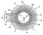
도 4는 자기 회로부에 서스펜션을 고착한 상태를 나타내는 축소 저면도이다.4 is a reduced bottom view illustrating a state in which a suspension is fixed to a magnetic circuit unit.
도 5는 분해 사시도이다.5 is an exploded perspective view.
<부호의 설명><Description of the code>
A : 다기능형 진동 액추에이터 1 : 하우징A: Multifunctional Vibration Actuator 1: Housing
2 : 자기 회로부 2a : 자기 공극부2:
3 : 서스펜션3: suspension
3e : 고착예정 위치(레이저 용착용 관통 구멍)3e: Predetermined position (through hole for laser welding)
4 : 다이어프램 5 : 보이스코일4: Diaphragm 5: Voice coil
이하, 본 발명의 일 실시예를 도면에 의거하여 설명한다. 본 발명의 다기능형 진동 액추에이터(A)는, 도 1 내지 도 5에 나타낸 바와 같이, 원통형상의 하우징(1) 내에 자기 회로부(2)와, 이 자기 회로부(2)를 하방으로부터 탄성적으로 지지하는 서스펜션(3)과, 그 자기 회로부(2)에 대향 배치되는 다이어프램(4)과, 이 다이어프램(4)에 고착되어 자기 회로부(2)의 환상의 자기 공극부(2a)에 삽입되는 보이스 코일(5)을 구비하고, 이 보이스 코일(5)에 음성신호를 입력하면, 다이어프램(4)이 미진동하여 착신음, 멜로디음, 음성, 음악 등의 소리를 발하고, 또, 진동 주파수 120∼160Hz의 신호전류가 흐르면, 자기 회로부(2)와 서스펜션(3)을 포함하는 중량이 있는 기계 진동계가 크게 진동하도록 되어 있다.Hereinafter, an embodiment of the present invention will be described with reference to the drawings. As shown in FIGS. 1 to 5, the multifunctional vibration actuator A of the present invention elastically supports the
하우징(1)은, 자기 회로부(2)를 수용하는 원통형상의 케이스로, 그 한쪽(도면에서는 상방)의 개구단(1a)에는, 다이어프램(4)의 외주부(4a)가 접착제 등으로 고착되고, 다른쪽(도면에서는 하방)의 개구단(1b)에는, 저면 커버(6)가 착탈 가능하게 장착됨으로써 덮고 있다.The
이들 하우징(1)의 다른쪽 개구단(1b)과 커버(6) 사이에는, 자기 회로부(2)에 고착된 서스펜션(3)의 바깥 가장자리부(3a)와 탄성 변형 가능한 환상부재(7)를 끼워 넣어, 하우징(1)의 다른쪽 개구단(1b)에 대해 서스펜션(3)의 외주 가장자리부(3a)를 압접시켜 고정하고 있다.Between the other
이 환상부재(7)란, 예를 들면 합성 고무 등의 탄성부재로 형성된 O링으로, 도 1, 도 3 및 도 5에 나타내는 바와 같이, 서스펜션(3)의 바깥 가장자리부(3a)와 대향하여 커버(6)의 저부 외주를 따라 배치된다. 또, 환상부재(7)로서, 상하 두께 방향의 사이즈가 다른 것이나 경도가 다른 것을 각각 복수 종류 준비하고, 이들 중에서 상황에 맞춰 선택하는 것이 바람직하다.The
그리고, 이들 하우징(1)과 커버(6)의 접합 부분에는 상호의 접근에 의해 끼워 맞춰 결합하는 결합수단(8)을 설치한다. 본 실시예의 경우에는 도 3 및 도 5에 나타내는 바와 같이, 바닥이 있는 원통형상 커버(6)의 측주벽(6a)과 하우징(1)의 하부 주측벽(1c)을 서로 끼워 맞추는 구조로 형성하고, 이들 끼워 맞춤면에 상기 결합수단(8)으로서 결합 볼록부(8a)와 결합 오목부(8b)를 각각 둘레방향으로 같은 간격마다 복수개씩 형성되어 있다.And the joining part 8 which fits and couples by mutual access is provided in the junction part of these
도시 예에서는 하우징(1)의 하부 주측벽(1c)의 외경과 커버(6)의 측주벽(6a)의 내경을 대략 동일하게 하여 끼워 맞춤과 동시에, 하우징(1)의 하부 주측벽(1c)의 외면에 결합 볼록부(8a)를 돌출 설치하고, 이와 대향하는 커버(6)의 측주벽(6a) 의 내면에 결합 오목부(8b)를 관통되게 관통되어 있는데, 상기 끼워 맞춤 구조 및 결합수단(8)의 형상은 도시한 것에 한정되지 않고, 동일한 기능이 있으면 결합 볼록부(8a)와 결합 오목부(8b)를 역으로 배치하거나 다른 구조나 형상이어도 된다.In the illustrated example, the outer circumference of the lower
서스펜션(5)은 링형상의 판 스프링으로, 그 중앙에 후술하는 자기 회로부(2)와 끼워 맞추는 중심 구멍(3b)과, 이 중심 구멍(3b)을 둘러싸고 자기 회로부(2)에 맞닿는 원환부(3c)와, 이 원환부(3c)와 상기 바깥 가장자리부(3a)를 연계하여 휨 변형하는 암(3d)이 형성되고, 그 원환부(3c)를 자기 회로부(2)에 레이저 용착으로 일체적으로 고정함과 동시에, 바깥 가장자리부(3a)를 하우징(1)의 다른쪽 개구단(1b)에 고정함으로써, 다이어프램(4)과 대향하는 위치에서 자기 회로부(2)를 탄성적으로 지지하고 있다.The
더 상세하게 설명하면, 도 4 및 도 5에 나타내는 바와 같이, 원환부(3c)의 복수 개소에, 고착예정 위치로서 미리 레이저 용착용 레이저가 통하는 관통 구멍(3e)을 각각 같은 간격마다 복수개씩 뚫어두고, 이들 복수의 관통 구멍(3e) 중에서, 탑재할 서스펜션(3)의 특성이나 자기 회로부(2)의 중량에 대응하는 관통 구멍(3e)을 선택하고, 이를 향해 레이저 조사 위치를 바꾸어 레이저 용착함으로써, 이 레이저 용착 위치로부터 하우징(1)의 다른쪽 개구단(1b)에 고정되는 서스펜션(3)의 바깥 가장자리부(3a), 즉 진동 중심 위치까지의 길이를 바꾸어, 그 서스펜션(3)에 의한 진동을 원하는 주파수를 정밀하게 맞추고 있다.More specifically, as shown in Fig. 4 and Fig. 5, a plurality of through-
다이어프램(4)은, 예를 들면 폴리카보네이트, 폴리에테르이미드, 폴리이미드, 폴리에틸렌프탈레이트의 플라스틱 필름 등의 탄성 재료로 적절한 두께의 평면 원형상으로 형성된 진동판으로, 그 외주 가장자리 근처를 하우징(1)의 내주면을 따라 구부려 원환상의 라이징부(4b)를 굴곡 형성하고, 이 라이징부(4b)로부터 하우징(1)의 한쪽 개구단(1a)의 평탄면과 평행하게 연장되는 외주부(4a)가 굴곡 형성된다.The
또, 다이어프램(4)의 반경 대략 중간위치에는, 원환상의 장치부(4c)를 형성하고, 그 이면에 보이스 코일(5)의 단면을 접착제 등으로 고착하여 자기 회로부(2)의 환상의 자기 공극부(2a)에 삽입시키고, 이 코일 장치부(4c)를 끼고 중심측 및 외주측에는, 바깥쪽으로 돌출하는 동심원 형상의 곡면부(4d, 4e)를 각각 굴곡 형성하고 있다.Further, an
보이스 코일(5)은 원통형상으로 감겨, 도 2에 나타낸 바와 같이, 그 리드선(5a)을 접착제 등에 의해 다이어프램(4)의 이면에 그 진동에 악영향이 없도록 부착하고, 이 리드선(5a)의 선단을 하우징(1)의 외측에 설치된 단자대(1d)를 향해 도출함과 동시에, 이 단자대(1d)에 설치된 단자 금구(1e)에 땜납 또는 본딩 등으로 전기적으로 접합시키고 있다.The
그리고, 상기 자기 회로부(2)는, 요크(9)와, 원반형상의 마그넷(10)과, 원반형상의 폴피스(Pole Piece)(11)를 동심축 상에 포개어 구성되어 있다.The
요크(9)는, 자성재로 바닥이 있는 원통형상으로 형성되어 있고, 그 외주면(9a)이 상기 하우징(1)의 내주면(1a)에 대해 미소 간극(예를 들면, 0.05∼0.2mm)을 사이에 두고 위치하도록 형성됨과 동시에, 하우징(1)의 내주면에 형성된 환상 단부(1f)와 대향하는 맞닿는면(9b)을 형성하고, 자기 회로부(2)의 진동시에 양자가 맞 닿아, 자기 회로부(2)의 외부 충격에 의한 이동을 제한하도록 되어 있다.The
또 본 실시예의 경우에는, 요크(9)의 하면에 서스펜션(3)의 중심 구멍(3b)과 끼워 맞추는 볼록부(9c)를 설치하고, 이 볼록부(9c)의 주위에 형성된 오목부(9d)에, 서스펜션(3)의 원환부(3c)가 맞닿아 레이저 용착 등으로 일체적으로 고정되어 있다. 또, 필요에 따라 저부 중앙에는, 마그넷(10)을 위치 결정하기 위해, 그 마그넷(10)의 직경과 대략 같은 직경의 카운터 보어부(counterbore)(도시하지 않음)를 오목하게 설치해도 된다.In the present embodiment, the
폴피스(11)는, 마그넷(10)의 직경과 대략 같은 직경 또는 그보다 대경인 원반형상으로 형성되어 있고, 필요에 따라 저면에는, 마그넷(10)을 위치 결정하기 위해, 그 마그넷(10)의 직경과 대략 같은 직경의 카운터 보어부(도시하지 않음)를 오목하게 설치해도 된다. 이것과 상기 요크(9)의 카운터 보어부에서 마그넷(10)를 끼워 넣음으로써, 마그넷(10)의 직경 방향의 위치 어긋남을 규제하면 더 바람직하다.The
다음으로, 이러한 다기능형 진동 액추에이터(A)의 조립 방법을 순서에 따라설명한다. 도 3에 나타내는 바와 같이, 우선 하우징(1)에 다이어프램(4)과 보이스 코일(5)을 일체적으로 장치하고, 자기 회로부(2)의 요크(9)에 서스펜션(3)을 레이저 용착으로 자기 회로부(2) 전체와 일체화시키고, 바닥이 있는 원통형상의 커버(6) 중에 환상 부재(7)를 넣고, 그 측주벽(6a)을 따라 얹는다.Next, the assembly method of such a multifunctional vibration actuator A is demonstrated in order. As shown in FIG. 3, first, the
또, 자기 회로부(2)의 요크(9)와 서스펜션(3)의 원환부(3c)를 레이저 용착할 때에는, 적어도 제조 로트마다 탑재할 서스펜션(3)의 특성이나 자기 회로부(2)의 중량을 조사하고, 그들에 대응하는 관통 구멍(3e)을 선택하고, 이를 향해 레이저 조사 위치를 바꾸어 레이저 용착함으로써, 이 레이저 용착 위치로부터 그 서스펜셔(3)과 하우징과의 진동 중심 위치까지의 길이를 바꾸어, 서스펜션(3)에 의한 진동을 원하는 주파수를 정밀하게 맞출 필요가 있다. 그 결과, 조립중에 서스펜션에 의한 진동 주파수를 정밀하게 맞출 수 있다.When the
그리고, 이 환상부재(7) 상에, 자기 회로부(2)와 일체화된 서스펜션(3)의 바깥 가장자리부(3a)를 겹쳐 쌓고, 그 위로부터 다이어프램(4) 및 보이스 코일(5)이 장치된 하우징(1)을 내려놓고, 그 다른쪽 개구단(1b)과 상기 커버(6) 사이에, 서스펜션(3)의 바깥 가장자리부(3a)와 환상부재(7)를 끼워 넣는다.Then, on the
그에 의해, 하우징(1)의 하부 주측벽(1c)과 커버(6)의 측주벽(6a)이 서로 접근하여 끼워 맞춤과 동시에, 이들 양자에 설치한 결합 수단(8)의 결합 볼록부(6a) 와 결합 오목부(6b)가 끼워 맞춰 결합되어, 모든 부품인 하우징(1)과 자기 회로부(2)와 서스펜션(3)과 다이어프램(4)과 보이스 코일(5)과 커버(6)와 환상부재(7)가 일체적으로 조립되어, 조립이 완성된다.As a result, the lower
따라서, 접착제나 형성형(型成形)이나 용착 등의 고착수단을 이용하지 않고 하우징(1)과 서스펜션(3)을 고정할 수 있음과 동시에, 하우징(1)의 밖으로부터 충격을 주어도, 환상부재(7)가 압축 변형하여 충격이 흡수된다. 그 결과, 공수나 비용의 삭감을 도모하면서 낙하 등의 충격에 의한 특성 변동을 방지하고, 또한 진동 주파수 특성을 평탄하게 할 수 있다. 또, 환상부재(7)의 사이즈나 경도를 바꿈으로써, 서스펜션(3)의 바깥 가장자리부(3a)에 대한 압접력이 변화하고, 그에 의해 공진 주파수를 조정할 수 있다.Therefore, the
또, 앞에 나타낸 실시예에서는, 자기 회로부(2)를 하방으로부터 서스펜션(3)으로 탄성적으로 지지하는 경우를 나타냈는데, 이에 한정되지 않고, 예를 들면 자기 회로부(2)를 상방으로부터 서스펜션(3)으로 매달아 지지하는 등, 자기 회로부(2)와 서스펜션(3)의 장치 방향이 바뀌어도 상술한 작용 효과가 얻어진다. 또, 앞에 나타낸 실시예에서 서술한 하우징(1), 자기 회로부(2), 서스펜션(3), 다이어프램(4), 보이스코일(5), 커버(6) 및 환상부재(7)의 구조 및 형상은 도시한 것에 한정되지 않고, 상술한 기능과 동일한 기능이면 다른 구조 및 형상이어도 된다.Moreover, although the case shown to support the
본 발명은, 조립중에 서스펜션에 의한 진동 주파수를 정밀하게 맞추며, 간단한 조정 구조이면서 고속으로, 또한 정확한 고착을 가능하게 하는 다기능형 액추에이터 및 휴대 단말기에 이용가능하다.The present invention is applicable to multifunctional actuators and portable terminals that precisely adjust the vibration frequency due to the suspension during assembly and enable simple fastening, high speed, and accurate fastening.
Claims (3)
Translated fromKoreanApplications Claiming Priority (2)
| Application Number | Priority Date | Filing Date | Title |
|---|---|---|---|
| JP2004082330AJP4475993B2 (en) | 2004-03-22 | 2004-03-22 | Multi-function vibration actuator and portable terminal device |
| JPJP-P-2004-00082330 | 2004-03-22 |
Publications (2)
| Publication Number | Publication Date |
|---|---|
| KR20060123622Atrue KR20060123622A (en) | 2006-12-01 |
| KR100852033B1 KR100852033B1 (en) | 2008-08-13 |
Family
ID=34994093
Family Applications (1)
| Application Number | Title | Priority Date | Filing Date |
|---|---|---|---|
| KR1020067018674AExpired - Fee RelatedKR100852033B1 (en) | 2004-03-22 | 2005-03-18 | Multifunctional Vibration Actuator and Handheld Device |
Country Status (8)
| Country | Link |
|---|---|
| US (1) | US7528509B2 (en) |
| EP (1) | EP1742504B1 (en) |
| JP (1) | JP4475993B2 (en) |
| KR (1) | KR100852033B1 (en) |
| CN (1) | CN1934901B (en) |
| DE (1) | DE602005021213D1 (en) |
| TW (1) | TW200533057A (en) |
| WO (1) | WO2005091674A1 (en) |
Families Citing this family (27)
| Publication number | Priority date | Publication date | Assignee | Title |
|---|---|---|---|---|
| DK200501409A (en)* | 2005-10-07 | 2007-04-08 | Tymphany Denmark As | Electroacoustic transducer |
| CN1992996B (en)* | 2005-12-30 | 2012-02-29 | 丁轶 | Detachable supporting structure for loudspeaker diaphragm |
| KR100675041B1 (en) | 2006-02-02 | 2007-01-29 | 삼성전기주식회사 | How to adjust the leaf spring stiffness of the actuator |
| KR101135396B1 (en)* | 2006-07-03 | 2012-04-17 | 아이필유(주) | Multi-function micro speaker |
| WO2008078640A1 (en)* | 2006-12-25 | 2008-07-03 | Nikon Corporation | Oscillation actuator, lens barrel and camera |
| KR100902120B1 (en)* | 2008-10-15 | 2009-06-09 | 주식회사 비에스이 | Multifunction speaker |
| JP4680291B2 (en)* | 2008-10-31 | 2011-05-11 | 哲郎 渡邊 | Multifunctional vibration generator |
| WO2011013462A1 (en)* | 2009-07-29 | 2011-02-03 | 三洋電機株式会社 | Electroacoustic transducer having vibration function |
| EP2355544A1 (en)* | 2009-12-21 | 2011-08-10 | Nxp B.V. | Suspension member for a vibration actuator |
| KR101206560B1 (en)* | 2010-01-05 | 2012-11-29 | 엘지이노텍 주식회사 | Voice coil motor |
| KR101046003B1 (en) | 2010-11-17 | 2011-07-04 | 삼성전기주식회사 | Linear oscillator |
| CN201967124U (en)* | 2011-01-07 | 2011-09-07 | 瑞声光电科技(常州)有限公司 | Electromagnetic loudspeaker |
| JP5781831B2 (en)* | 2011-05-25 | 2015-09-24 | 日本電産サンキョー株式会社 | Optical device and method of manufacturing optical device |
| KR101339551B1 (en)* | 2011-09-05 | 2013-12-10 | 삼성전기주식회사 | Linear vibrator |
| KR101288147B1 (en)* | 2011-11-16 | 2013-07-18 | 삼성전기주식회사 | Haptic feedback device |
| US8890375B2 (en)* | 2012-07-05 | 2014-11-18 | Aac Acoustic Technologies (Shenzhen) Co., Ltd. | Multi-function vibrating device |
| US9628902B2 (en)* | 2015-09-22 | 2017-04-18 | Meiloon Industrial Co., Ltd. | Passive radiator structure |
| DK3151582T3 (en) | 2015-09-30 | 2020-10-12 | Apple Inc | HEADPHONE WITH CHARGING SYSTEM CASE |
| JP2019221046A (en)* | 2018-06-19 | 2019-12-26 | 日本電産コパル株式会社 | Vibration actuator |
| US10531202B1 (en)* | 2018-08-13 | 2020-01-07 | Google Llc | Reduced thickness actuator |
| JP2021132395A (en)* | 2018-08-13 | 2021-09-09 | グーグル エルエルシーGoogle LLC | Thinned actuator |
| US11172101B1 (en) | 2018-09-20 | 2021-11-09 | Apple Inc. | Multifunction accessory case |
| JP7180417B2 (en)* | 2019-01-30 | 2022-11-30 | オムロンヘルスケア株式会社 | Biological information measuring device |
| US11240579B2 (en)* | 2020-05-08 | 2022-02-01 | Level 42 Ai | Sensor systems and methods for characterizing health conditions |
| US12174660B2 (en) | 2020-06-11 | 2024-12-24 | Apple Inc. | Electronic device |
| US11573599B2 (en)* | 2020-06-11 | 2023-02-07 | Apple Inc. | Electrical connectors for electronic devices |
| US20240015445A1 (en)* | 2020-09-04 | 2024-01-11 | Level 42 Ai Inc. | Non-contact sensor systems and methods |
Family Cites Families (15)
| Publication number | Priority date | Publication date | Assignee | Title |
|---|---|---|---|---|
| JP3246123B2 (en)* | 1993-09-30 | 2002-01-15 | 松下電器産業株式会社 | Sounder and method of manufacturing the same |
| JPH08129845A (en)* | 1994-10-31 | 1996-05-21 | Mitsumi Electric Co Ltd | Suspension assembling structure of magnetic field modulation head |
| TW353849B (en)* | 1996-11-29 | 1999-03-01 | Matsushita Electric Industrial Co Ltd | Electric-to-mechanical-to-acoustic converter and portable terminal unit |
| JPH117286A (en) | 1997-06-18 | 1999-01-12 | Sanyo Electric Co Ltd | Siren for joint use for sound/vibration |
| US6084330A (en)* | 1998-03-13 | 2000-07-04 | Kollmorgen Corporation | Permanent magnet rotor and method of assembly |
| JP3704977B2 (en)* | 1998-11-20 | 2005-10-12 | 松下電器産業株式会社 | Electro-mechanical-acoustic transducer |
| JP4565130B2 (en) | 2000-12-22 | 2010-10-20 | 並木精密宝石株式会社 | Multi-function sound generator and portable terminal |
| JP3797916B2 (en) | 2001-10-30 | 2006-07-19 | シチズン電子株式会社 | Speaker and manufacturing method thereof |
| CN1273226C (en) | 2001-12-28 | 2006-09-06 | 并木精密宝石株式会社 | Multi-functional vibrating actuator |
| US7324655B2 (en)* | 2002-07-04 | 2008-01-29 | Nec Tokin Corporation | Electroacoustic transducer |
| JP3891414B2 (en) | 2002-07-05 | 2007-03-14 | シチズン電子株式会社 | Electroacoustic transducer manufacturing method |
| EP1542497B1 (en)* | 2002-09-06 | 2011-11-02 | Namiki Seimitsu Houseki Kabushiki Kaisha | Loudspeaker with vibrating function for a portable terminal |
| EP1562397B1 (en)* | 2002-10-24 | 2013-12-04 | Panasonic Corporation | Electroacoustic transducer with vibration function and its manufacturing method |
| US7003130B2 (en)* | 2003-01-29 | 2006-02-21 | Samsung Electro-Mechanics Co., Ltd. | Resonance frequency correction method and vibration speaker |
| JP2006203709A (en)* | 2005-01-24 | 2006-08-03 | Citizen Electronics Co Ltd | Oscillator |
- 2004
- 2004-03-22JPJP2004082330Apatent/JP4475993B2/ennot_activeExpired - Fee Related
- 2005
- 2005-02-05TWTW094103969Apatent/TW200533057A/ennot_activeIP Right Cessation
- 2005-03-18KRKR1020067018674Apatent/KR100852033B1/ennot_activeExpired - Fee Related
- 2005-03-18EPEP05721097Apatent/EP1742504B1/ennot_activeExpired - Lifetime
- 2005-03-18DEDE602005021213Tpatent/DE602005021213D1/ennot_activeExpired - Lifetime
- 2005-03-18CNCN2005800091885Apatent/CN1934901B/ennot_activeExpired - Fee Related
- 2005-03-18WOPCT/JP2005/004910patent/WO2005091674A1/enactiveApplication Filing
- 2005-03-18USUS10/592,958patent/US7528509B2/ennot_activeExpired - Fee Related
Also Published As
| Publication number | Publication date |
|---|---|
| CN1934901A (en) | 2007-03-21 |
| WO2005091674A1 (en) | 2005-09-29 |
| TWI347081B (en) | 2011-08-11 |
| US20070194633A1 (en) | 2007-08-23 |
| EP1742504A4 (en) | 2008-05-21 |
| TW200533057A (en) | 2005-10-01 |
| US7528509B2 (en) | 2009-05-05 |
| CN1934901B (en) | 2012-08-08 |
| DE602005021213D1 (en) | 2010-06-24 |
| EP1742504A1 (en) | 2007-01-10 |
| JP2005269497A (en) | 2005-09-29 |
| KR100852033B1 (en) | 2008-08-13 |
| EP1742504B1 (en) | 2010-05-12 |
| JP4475993B2 (en) | 2010-06-09 |
Similar Documents
| Publication | Publication Date | Title |
|---|---|---|
| KR100852033B1 (en) | Multifunctional Vibration Actuator and Handheld Device | |
| JP2007184812A (en) | Vibrator and method of manufacturing same | |
| EP2432251A1 (en) | Multifunctional micro speaker | |
| KR100975891B1 (en) | Multifunctional Actuator and Handheld Device | |
| JP4867031B2 (en) | Multi-function vibration actuator | |
| KR20190100636A (en) | Mobile apparatus having linear actuator generating both vibration and sound | |
| JP2013233537A (en) | Vibrator | |
| KR20210002223U (en) | Acoustic transducer with balanced | |
| KR100786928B1 (en) | Multi-function type oscillation actuator and mobile terminal device | |
| JP4299263B2 (en) | Vibration actuator | |
| KR100427101B1 (en) | Multi functional sound generating device and portable terminal | |
| KR20160081641A (en) | Earphone and manufacturing method for earphone | |
| KR100519823B1 (en) | A multi-function actuator | |
| KR102127981B1 (en) | Vibration motor | |
| KR102306513B1 (en) | Wide band linear motor | |
| JP2019092113A (en) | Sound producing device | |
| KR100558452B1 (en) | Sound generator | |
| KR102167407B1 (en) | Wide band linear motor | |
| WO2019098181A1 (en) | Sound production device | |
| JP2005269496A (en) | Multi-function vibration actuator and assembly method thereof | |
| CN118574062A (en) | Vibration sounding device, vibration sounding module, assembly method of vibration sounding module and electronic terminal | |
| KR20210117817A (en) | Solenoid Speaker | |
| JPH0795688A (en) | Horn loudspeaker |
Legal Events
| Date | Code | Title | Description |
|---|---|---|---|
| PA0105 | International application | St.27 status event code:A-0-1-A10-A15-nap-PA0105 | |
| A201 | Request for examination | ||
| PA0201 | Request for examination | St.27 status event code:A-1-2-D10-D11-exm-PA0201 | |
| PG1501 | Laying open of application | St.27 status event code:A-1-1-Q10-Q12-nap-PG1501 | |
| E902 | Notification of reason for refusal | ||
| PE0902 | Notice of grounds for rejection | St.27 status event code:A-1-2-D10-D21-exm-PE0902 | |
| T11-X000 | Administrative time limit extension requested | St.27 status event code:U-3-3-T10-T11-oth-X000 | |
| P11-X000 | Amendment of application requested | St.27 status event code:A-2-2-P10-P11-nap-X000 | |
| P13-X000 | Application amended | St.27 status event code:A-2-2-P10-P13-nap-X000 | |
| E701 | Decision to grant or registration of patent right | ||
| PE0701 | Decision of registration | St.27 status event code:A-1-2-D10-D22-exm-PE0701 | |
| GRNT | Written decision to grant | ||
| PR0701 | Registration of establishment | St.27 status event code:A-2-4-F10-F11-exm-PR0701 | |
| PR1002 | Payment of registration fee | St.27 status event code:A-2-2-U10-U12-oth-PR1002 Fee payment year number:1 | |
| PG1601 | Publication of registration | St.27 status event code:A-4-4-Q10-Q13-nap-PG1601 | |
| R17-X000 | Change to representative recorded | St.27 status event code:A-5-5-R10-R17-oth-X000 | |
| PR1001 | Payment of annual fee | St.27 status event code:A-4-4-U10-U11-oth-PR1001 Fee payment year number:4 | |
| PR1001 | Payment of annual fee | St.27 status event code:A-4-4-U10-U11-oth-PR1001 Fee payment year number:5 | |
| FPAY | Annual fee payment | Payment date:20130709 Year of fee payment:6 | |
| PR1001 | Payment of annual fee | St.27 status event code:A-4-4-U10-U11-oth-PR1001 Fee payment year number:6 | |
| FPAY | Annual fee payment | Payment date:20140603 Year of fee payment:7 | |
| PR1001 | Payment of annual fee | St.27 status event code:A-4-4-U10-U11-oth-PR1001 Fee payment year number:7 | |
| LAPS | Lapse due to unpaid annual fee | ||
| PC1903 | Unpaid annual fee | St.27 status event code:A-4-4-U10-U13-oth-PC1903 Not in force date:20150807 Payment event data comment text:Termination Category : DEFAULT_OF_REGISTRATION_FEE | |
| P22-X000 | Classification modified | St.27 status event code:A-4-4-P10-P22-nap-X000 | |
| PC1903 | Unpaid annual fee | St.27 status event code:N-4-6-H10-H13-oth-PC1903 Ip right cessation event data comment text:Termination Category : DEFAULT_OF_REGISTRATION_FEE Not in force date:20150807 | |
| P22-X000 | Classification modified | St.27 status event code:A-4-4-P10-P22-nap-X000 | |
| PN2301 | Change of applicant | St.27 status event code:A-5-5-R10-R13-asn-PN2301 St.27 status event code:A-5-5-R10-R11-asn-PN2301 | |
| PN2301 | Change of applicant | St.27 status event code:A-5-5-R10-R13-asn-PN2301 St.27 status event code:A-5-5-R10-R11-asn-PN2301 |