KR20060121861A - Laryngeal Mask Airway Device with Positioning Handle - Google Patents
Laryngeal Mask Airway Device with Positioning HandleDownload PDFInfo
- Publication number
- KR20060121861A KR20060121861AKR1020067004744AKR20067004744AKR20060121861AKR 20060121861 AKR20060121861 AKR 20060121861AKR 1020067004744 AKR1020067004744 AKR 1020067004744AKR 20067004744 AKR20067004744 AKR 20067004744AKR 20060121861 AKR20060121861 AKR 20060121861A
- Authority
- KR
- South Korea
- Prior art keywords
- patient
- handle
- cuff
- airway
- tube
- Prior art date
- Legal status (The legal status is an assumption and is not a legal conclusion. Google has not performed a legal analysis and makes no representation as to the accuracy of the status listed.)
- Ceased
Links
- 238000003780insertionMethods0.000claimsabstractdescription31
- 230000037431insertionEffects0.000claimsabstractdescription31
- 210000002409epiglottisAnatomy0.000claimsdescription16
- 239000002390adhesive tapeSubstances0.000claimsdescription15
- 210000005070sphincterAnatomy0.000claimsdescription11
- 239000000463materialSubstances0.000claimsdescription8
- 210000000867larynxAnatomy0.000claimsdescription4
- 238000000034methodMethods0.000claims2
- 239000007787solidSubstances0.000claims1
- 238000009423ventilationMethods0.000claims1
- 239000003550markerSubstances0.000description6
- 210000003484anatomyAnatomy0.000description4
- 238000001746injection mouldingMethods0.000description4
- 230000000903blocking effectEffects0.000description3
- 210000004072lungAnatomy0.000description3
- 206010002091AnaesthesiaDiseases0.000description2
- 230000037005anaesthesiaEffects0.000description2
- 238000001514detection methodMethods0.000description2
- 239000000314lubricantSubstances0.000description2
- 210000000056organAnatomy0.000description2
- 239000004033plasticSubstances0.000description2
- 210000003437tracheaAnatomy0.000description2
- 239000004677NylonSubstances0.000description1
- 208000003443UnconsciousnessDiseases0.000description1
- QVGXLLKOCUKJST-UHFFFAOYSA-Natomic oxygenChemical compound[O]QVGXLLKOCUKJST-UHFFFAOYSA-N0.000description1
- 238000012790confirmationMethods0.000description1
- 239000013013elastic materialSubstances0.000description1
- 210000003238esophagusAnatomy0.000description1
- 238000009434installationMethods0.000description1
- 238000004519manufacturing processMethods0.000description1
- 238000012986modificationMethods0.000description1
- 230000004048modificationEffects0.000description1
- 229920001778nylonPolymers0.000description1
- 229910052760oxygenInorganic materials0.000description1
- 239000001301oxygenSubstances0.000description1
- 210000003800pharynxAnatomy0.000description1
- 239000004417polycarbonateSubstances0.000description1
- 229920000515polycarbonatePolymers0.000description1
- 230000001954sterilising effectEffects0.000description1
- 238000004659sterilization and disinfectionMethods0.000description1
- 230000037303wrinklesEffects0.000description1
Images


Classifications
- A—HUMAN NECESSITIES
- A61—MEDICAL OR VETERINARY SCIENCE; HYGIENE
- A61M—DEVICES FOR INTRODUCING MEDIA INTO, OR ONTO, THE BODY; DEVICES FOR TRANSDUCING BODY MEDIA OR FOR TAKING MEDIA FROM THE BODY; DEVICES FOR PRODUCING OR ENDING SLEEP OR STUPOR
- A61M16/00—Devices for influencing the respiratory system of patients by gas treatment, e.g. ventilators; Tracheal tubes
- A61M16/04—Tracheal tubes
- A61M16/0402—Special features for tracheal tubes not otherwise provided for
- A61M16/0409—Special features for tracheal tubes not otherwise provided for with mean for closing the oesophagus
- A—HUMAN NECESSITIES
- A61—MEDICAL OR VETERINARY SCIENCE; HYGIENE
- A61M—DEVICES FOR INTRODUCING MEDIA INTO, OR ONTO, THE BODY; DEVICES FOR TRANSDUCING BODY MEDIA OR FOR TAKING MEDIA FROM THE BODY; DEVICES FOR PRODUCING OR ENDING SLEEP OR STUPOR
- A61M16/00—Devices for influencing the respiratory system of patients by gas treatment, e.g. ventilators; Tracheal tubes
- A61M16/04—Tracheal tubes
- A61M16/0402—Special features for tracheal tubes not otherwise provided for
- A61M16/0418—Special features for tracheal tubes not otherwise provided for with integrated means for changing the degree of curvature, e.g. for easy intubation
- A—HUMAN NECESSITIES
- A61—MEDICAL OR VETERINARY SCIENCE; HYGIENE
- A61M—DEVICES FOR INTRODUCING MEDIA INTO, OR ONTO, THE BODY; DEVICES FOR TRANSDUCING BODY MEDIA OR FOR TAKING MEDIA FROM THE BODY; DEVICES FOR PRODUCING OR ENDING SLEEP OR STUPOR
- A61M16/00—Devices for influencing the respiratory system of patients by gas treatment, e.g. ventilators; Tracheal tubes
- A61M16/04—Tracheal tubes
- A61M16/0434—Cuffs
- A61M16/0445—Special cuff forms, e.g. undulated
- A—HUMAN NECESSITIES
- A61—MEDICAL OR VETERINARY SCIENCE; HYGIENE
- A61M—DEVICES FOR INTRODUCING MEDIA INTO, OR ONTO, THE BODY; DEVICES FOR TRANSDUCING BODY MEDIA OR FOR TAKING MEDIA FROM THE BODY; DEVICES FOR PRODUCING OR ENDING SLEEP OR STUPOR
- A61M16/00—Devices for influencing the respiratory system of patients by gas treatment, e.g. ventilators; Tracheal tubes
- A61M16/04—Tracheal tubes
- A61M16/0488—Mouthpieces; Means for guiding, securing or introducing the tubes
- A—HUMAN NECESSITIES
- A61—MEDICAL OR VETERINARY SCIENCE; HYGIENE
- A61M—DEVICES FOR INTRODUCING MEDIA INTO, OR ONTO, THE BODY; DEVICES FOR TRANSDUCING BODY MEDIA OR FOR TAKING MEDIA FROM THE BODY; DEVICES FOR PRODUCING OR ENDING SLEEP OR STUPOR
- A61M16/00—Devices for influencing the respiratory system of patients by gas treatment, e.g. ventilators; Tracheal tubes
- A61M16/04—Tracheal tubes
- A61M16/0402—Special features for tracheal tubes not otherwise provided for
- A61M16/0411—Special features for tracheal tubes not otherwise provided for with means for differentiating between oesophageal and tracheal intubation
Landscapes
- Health & Medical Sciences (AREA)
- Pulmonology (AREA)
- Animal Behavior & Ethology (AREA)
- General Health & Medical Sciences (AREA)
- Engineering & Computer Science (AREA)
- Anesthesiology (AREA)
- Biomedical Technology (AREA)
- Heart & Thoracic Surgery (AREA)
- Hematology (AREA)
- Life Sciences & Earth Sciences (AREA)
- Veterinary Medicine (AREA)
- Emergency Medicine (AREA)
- Public Health (AREA)
- Otolaryngology (AREA)
- Orthopedics, Nursing, And Contraception (AREA)
- Respiratory Apparatuses And Protective Means (AREA)
- Surgical Instruments (AREA)
- Prostheses (AREA)
- Arc Welding In General (AREA)
- Investigating, Analyzing Materials By Fluorescence Or Luminescence (AREA)
- Magnetically Actuated Valves (AREA)
- Endoscopes (AREA)
Abstract
Translated fromKoreanDescription
Translated fromKorean본 발명은 후두 마스크 기도 장치에 관한 것이다. 더욱 구체적으로, 본 발명은 장치의 위치 조절을 용이하게 하기 위해 장치의 근위부 말단 근처에 위치한 손잡이(tab)가 있는 후두 마스크 기도 장치에 관한 것이다.The present invention relates to a laryngeal mask airway device. More specifically, the present invention relates to a laryngeal mask airway device with a tab located near the proximal end of the device to facilitate positioning of the device.
후두 마스크 기도 장치는 무의식 상태의 환자에 기도를 확보하는 데 유용한 장치로 잘 알려져 있다. 한 유명 후두 마스크 기도 장치는 수년 동안 사이프러스(Cyprus)의 후두 마스크 회사에 의해 "클래식(Classic)"으로서 상업적으로 판매되어왔다. 이런 장치는 예를 들어, 미국특허 제4,509,514호에 기재되어 있다. 상기 클래식은 재사용이 가능한 장치이고 적어도 40회 멸균에도 견디는 것이 보장되고, 실제로 이러한 장치는 사용하기에 매우 낡기 전까지 일반적으로 40회 이상 멸균(재사용)할 수 있다. 최근 들어, 감소된 비용의 일회용 후두 마스크 기도 장치를 개발하고자 하는 시도가 이루어지고 있다.Laryngeal mask airway devices are well known as useful devices for securing airways in unconscious patients. One well-known laryngeal mask airway device has been sold commercially as "Classic" by Cyprus' laryngeal mask company for many years. Such a device is described, for example, in US Pat. No. 4,509,514. The classic is a reusable device and is guaranteed to withstand at least 40 sterilizations and in practice such a device can generally be sterilized (reuse) at least 40 times before being very old to use. Recently, attempts have been made to develop reduced cost disposable laryngeal mask airway devices.
도 1A, 도 1B 및 도 1C는 커프(cuff)가 팽창되었을 때 종래 일회용 후두 마스크 기도 장치(100)의 다양한 모습을 나타낸다. 도 2는 장치(100)가 환자에 삽입되었을 때의 해당 장치(100)의 단면도이다. 도 1A를 참고하면, 장치(100)는 기도튜브(110) 및 마스크부(130)를 포함한다. 마스크부(130)는 평편한 판(132) 및 팽창가능한 커프(134)를 포함한다. 상기 마스크부(130)는 근위부 말단(136)에서부터 원위부 말단(138)까지 뻗어있다. 마스크부(130)는 기도튜브(110)의 원위부(112)에 부착된다. 장치(100)는 또한 팽창 관(190)(도 1B에 나타냄) 및 선택적으로 팽창 및 수축하는 커프(134)를 위한 체크 밸브(check valve)(192)를 포함한다.1A, 1B, and 1C show various views of a conventional disposable laryngeal
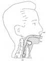
수술 시에, 상기 커프(134)는 수축되고, 이후 상기 마스크부는 환자의 입을 통하여 환자 인두까지 삽입된다. 상기 장치는 상기 마스크부(130)의 원위부 말단(138)이 환자의 정상적으로 닫혀있는 식도의 반대편에 있도록 하고 상기 마스크부(130)의 개구부 말단(140)(도 1C에 나타냄)이 환자의 기관(trachea; 예를 들어, 환자의 성문 개구부)의 입구에 배치되도록 위치하는 것이 바람직하다. 상기 마스크부가 그와 같이 위치 결정된 후, 상기 커프가 팽창되고 환자의 성문 개구부(212) 주변에 씰(seal)이 형성되고, 이로 인해서 기도튜브(110)의 근위부 말단(114)에서부터 환자의 기관까지 뻗어있는 봉합된 기도가 확보된다.In operation, the
설명의 편의를 위하여, "완전히 삽입된 형태"는 여기서 환자에게 삽입된 후두 마스크 기도 장치를 의미하는 것이고 하기의 특성을 갖는다; (1) 상기 마스크부의 원위부 말단은 환자의 정상적으로 닫힌 식도 괄약근(sphincter)에 대항해서 눌러 압박된다; (2) 상기 커프는 팽창되고 환자의 성문 개구부 주변에 씰이 형성된 다; 및 (3) 상기 기도튜브는 환자의 입 외부에 위치한 근위부 말단으로부터 상기 마스크부에 연결되는 원위부까지 뻗어있어, 상기 장치가 상기 튜브의 근위부 말단에서부터 환자의 폐까지 뻗어있는 봉합된 기도를 제공하도록 환자의 입 및 환자의 원위 기도(natural upper airway)를 통하여 뻗게된다.For convenience of description, “fully inserted form” means here a laryngeal mask airway device inserted into a patient and has the following characteristics; (1) the distal end of the mask portion is pressed against the normally closed esophageal sphincter of the patient; (2) the cuff is inflated and a seal is formed around the patient's glottic opening; And (3) the airway tube extends from a proximal end located outside the patient's mouth to a distal connection to the mask portion such that the device provides a sealed airway extending from the proximal end of the tube to the patient's lung. It extends through the mouth and the patient's natural upper airway.
도 2는 완전히 삽입된 형태의 후두 마스크 기도 장치(100)를 나타낸다. 도 2에 나타낸 바와 같이, 상기 마스크부(130)의 원위부 말단은 환자의 식도 괄약근(210)에 대항해서 눌러 압박된다. 또한, 상기 마스크부의 개구부 말단은 성문 개구부(212) 주변에 씰을 형성함으로써 상기 장치(100)가 상기 기관(214)과 기류 교환을 할 수 있도록 한다.2 shows a laryngeal
비록 종래 일회용 후두 마스크 기도 장치가 잘 개발되었어도, 개선된 장치를 제공하기 위해서는 필요 사항이 남아있다. 특히, 일단 환자에 삽입된 상기 장치가 안정하게 완전히 삽입된 형태로 더욱 확실하게 유지되는 일회용 후두 마스크 기도 장치를 제공하기 위한 필요 사항이 남아 있다.Although conventional disposable laryngeal mask airway devices are well developed, a need remains to provide an improved device. In particular, a need remains to provide a disposable laryngeal mask airway device in which the device, once inserted into a patient, remains more reliably in a stable, fully inserted form.
본 발명에 따르면, 팽창되는 경우 적어도 중앙 개구부를 규정하고, 환자의 입을 통해 환자 내에 삽입위치까지 삽입될 수 있고, 팽창되어 상기 삽입위치에 있는 경우 환자의 성문 개구부를 둘러싸는 팽창가능한 커프; 근위부 말단에서부터 원위부 말단까지 뻗어, 내부 통로를 규정하는 기도튜브; 상기 커프가 팽창되어 상기 삽입위치에 있는 경우 튜브의 근위부 말단으로부터 상기 내부 통로를 통하여 성문 개구부까지 뻗어있는 봉합된 기도 통로; 및 상기 커프가 상기 삽입위치에 있을 때 환자의 입 외부에 배치되도록 하기 위해 상기 기도튜브의 근위부 말단 근처의 기도튜브에 배치된 손잡이를 포함하는 후두 마스크 기도 장치를 제공한다.According to the invention there is provided an apparatus, comprising: an inflatable cuff defining at least a central opening when inflated and being inserted into the patient through the mouth of the patient to an insertion position, the inflatable cuff surrounding the patient's gate opening when inflated; An airway tube extending from the proximal end to the distal end to define an internal passageway; A sealed airway passage extending from the proximal end of the tube to the gate opening through the inner passage when the cuff is inflated and in the insertion position; And a handle disposed on the airway tube near the proximal end of the airway tube for placement of the cuff outside the patient's mouth when the cuff is in the insertion position.
상기 장치는 상기 기도튜브의 근위부 말단 근처에 배치되는 손잡이를 포함한다. 상기 장치가 환자에 삽입되면, 상기 손잡이는 환자의 윗입술 근처에 위치하게 된다. 상기 손잡이는 접착 테이프가 손잡이 및 환자의 뺨에 부착될 수 있도록 편리하게 위치된다. 상기 테이프는 상기 장치가 일반적으로 환자에게로 치우쳐지도록, 보다 구체적으로, 상기 장치의 원위부 말단이 환자의 식도 괄약근에 대항해서 치우쳐지도록 힘을 가한다. 이는 상기 장치가 더욱 안정하게 완전히 삽입된 형태로 유지되도록 하고 역류되는 물질이 환자의 폐로 빨려들어 갈 가능성을 감소시킨다. 상기 장치는 후두개(epiglottis)를 지지하고 상기 장치에 의해 제공되는 기도 통로가 막히는 것으로부터 후두개를 보호하기 위하여 팽창가능한 커프 내에 플랜지(flange)를 또한 포함할 수 있다.The device includes a handle disposed near the proximal end of the airway tube. When the device is inserted into the patient, the handle is placed near the patient's upper lip. The handle is conveniently positioned so that the adhesive tape can be attached to the handle and the cheek of the patient. The tape exerts a force such that the device is generally biased towards the patient, and more specifically, the distal end of the device is biased against the patient's esophageal sphincter. This allows the device to remain in a more fully inserted form more stably and reduces the likelihood of backflowing material being sucked into the patient's lungs. The device may also include a flange in the inflatable cuff to support the epiglottis and to protect the epiglottis from clogging the airway passages provided by the device.
본 발명의 또 다른 목적 및 이점은 하기 상세한 설명으로 당업계의 숙련된 자에게 점차 명백해질 것이다. 여기서 몇몇 실시형태는 단순하게 본 발명의 설명에 의해 기술될 것이다.Still other objects and advantages of the invention will become apparent to those skilled in the art from the following detailed description. Here some embodiments will be described simply by way of explanation of the invention.
본 발명의 특성 및 목적의 완전한 이해를 위하여, 수반되는 도면과 연관하여 취해지는 하기의 상세한 설명에는 참조가 있어야 하고, 도면 내에서 동일한 참조 번호들이 동일 또는 유사한 부분을 표시하기 위해 사용된다:For a thorough understanding of the nature and objects of the present invention, the following detailed description taken in conjunction with the accompanying drawings shall be referred to, wherein like reference numerals are used to designate identical or similar parts in the drawings:
도 1A는 커프가 팽창될 경우 종래 일회용 후두 마스크 기도 장치의 측면도1A is a side view of a conventional disposable laryngeal mask airway device when the cuff is inflated
도 1B는 도 1A에 나타낸 상기 종래 장치의 뒷면의 사시도FIG. 1B is a perspective view of the back side of the conventional apparatus shown in FIG. 1A
도 1C는 도 1A에 나타낸 상기 종래 장치의 앞면의 사시도1C is a perspective view of the front side of the conventional device shown in FIG. 1A
도 2는 상기 장치가 완전히 삽입된 형태일 때 도 1A - 1C에 나타낸 상기 장치의 부분 측단면도2 is a partial side cross-sectional view of the device shown in FIGS. 1A-1C when the device is fully inserted;
도 3A는 커프가 팽창될 경우 본 발명에 의해 제조된 일회용 후두 마스크 기도 장치의 측면도3A is a side view of a disposable laryngeal mask airway device made by the present invention when the cuff is inflated;
도 3B는 도 3A에 나타낸 상기 장치의 뒷면의 사시도FIG. 3B is a perspective view of the back side of the device shown in FIG. 3A
도 4A는 도 3A 및 도 3B에 나타낸 상기 장치의 기도튜브의 분해 측면도4A is an exploded side view of the airway tube of the device shown in FIGS. 3A and 3B.
도 4B는 도 4A에 나타낸 화살표 4B-4B의 방향으로 취한 상기 기도튜브의 연결부의 평면도4B is a plan view of the connecting portion of the airway tube taken in the direction of
도 4C 및 도 4D는 도 4A에 나타낸 화살표 4C-4C 및 4D-4D 각각의 방향으로 취한 상기 기도튜브의 연결부의 밑면도4C and 4D are bottom views of the connection of the airway tube taken in the direction of arrows 4C-4C and 4D-4D respectively shown in FIG. 4A.
도 4E는 도 4에 나타낸 선 4E-4E를 따라 취한 상기 전체 튜브 및 뒷판부의 단면도4E is a cross-sectional view of the entire tube and back plate taken along
도 5는 완전히 삽입된 형태로 있을 때 본 발명에 의해 제조된 일회용 후두 마스크 기도 장치의 부분적으로 절개된 측단면도Figure 5 is a partially cut away side cross-sectional view of a disposable laryngeal mask airway device made by the present invention when in fully inserted form.
도 6은 완전히 삽입된 형태에서 안정적으로 유지되도록 하기 위해 접착 테이 프가 상기 손잡이 및 환자의 뺨에 붙여진 경우 본 발명에 의해 제조된 일회용 후두 마스크 기도 장치의 부분적으로 절개된 측단면도Fig. 6 is a partially cutaway side cross-sectional view of a disposable laryngeal mask airway device made by the present invention when an adhesive tape is attached to the handle and the cheek of the patient to ensure that it remains stable in the fully inserted form.
도 7A 내지 도 7G는 본 발명에 따라 제조된 손잡이들의 변형 형태들을 나타낸 도면7A-7G illustrate variants of handles made in accordance with the present invention.
도 8A는 도 3A에 나타낸 상기 장치의 앞면의 사시도8A is a perspective view of the front of the device shown in FIG. 3A
도 8B 및 도 8C는 도 8A에 나타낸 선 8B-8B 및 8C-8C를 따라 취한 상기 장치의 단면도8B and 8C are cross-sectional views of the device taken along
도 8D는 도 8A에 나타낸 상기 커프 내에 포함된 후두개 지지 플랜지의 모습을 나타낸 도면FIG. 8D is a view of the epiglottis support flange included in the cuff shown in FIG. 8A. FIG.
도 9는 후두 마스크 기도 장치에 의해 제공되는 상기 기도 통로가 막히는 것으로부터 후두개를 보호하기 위한 지지체의 일 형태를 나타낸다.9 shows one form of a support for protecting the epiglottis from clogging the airway passages provided by the laryngeal mask airway device.
도 10은 상기 장치가 환자에 삽입되고 환자의 후두개가 상기 장치에 의해 규정된 볼(bowl) 모양의 공간에 떨어질 때 도 8C와 같은 유리한 위치로부터 취한 장치의 단면도FIG. 10 is a cross-sectional view of the device taken from an advantageous position such as FIG. 8C when the device is inserted into the patient and the epiglottis of the patient falls into the bowl-shaped space defined by the device.
도 11은 본 발명에 따라 제조된 또 다른 후두 마스크 기도 장치의 단면도11 is a cross-sectional view of another laryngeal mask airway device made in accordance with the present invention.
도 12는 환자에 부분적으로 삽입된 후두 마스크 기도 장치를 나타낸 도면12 shows a laryngeal mask airway device partially inserted into a patient.
도 3A 및 도 3B는 각각 본 발명에 따라 제조된 개선된 일회용 후두 마스크 기도 장치(300)의 측면도 및 사시도를 나타낸다. 상기 장치(300)는 기도튜브(310) 및 팽창가능한 커프(334)를 포함한다. 상기 커프(334)는 근위부 말단(336)에서부터 원위부 말단(338)까지 뻗어있다. 상기 장치(300)는 커프(334)의 근위부 말단(336)에 연결된 팽창 관(390) 및 선택적으로 팽창 및 수축하는 커프(334)를 위한 체크 밸브(392)를 포함한다. 상기 장치(300)는 또한 손잡이(360)를 포함하며, 이는 기도튜브(310)에 완전히 부착된다. 하기에서 더 설명하겠지만, 손잡이(360)는 장치(300)가 완전히 삽입된 형태로 안정하게 유지되는 것을 유리하게 용이하게 한다.3A and 3B show side and perspective views, respectively, of an improved disposable laryngeal
도 4A는 커프(334)의 부착 전의 기도튜브(310)의 분해된 측면도를 나타낸다. 상기 도 4A에 나타낸 바와 같이, 기도튜브(310)는 연결부(400), 일체형 튜브·뒷판부(450)를 포함한다. 도 4B, 도 4C 및 도 4D는 도 4A에 나타낸 바와 같이, 화살표 4B-4B, 4C-4C 및 4D-4D 각각의 방향에서 취한 연결부(400)의 모습을 나타낸다.4A shows an exploded side view of the
상기 연결부(400)는 근위부(410), 원위부(420) 및 근위부(410)와 원위부(420)의 사이에 위치한 플랜지(430)를 포함한다. 손잡이(360)는 플랜지(430)의 일체형 부분으로서 형성된다. 근위부(410)는 원기둥형이고 표준 의학적 산소 공급 장치 또는 마취 장치와 연결되도록 구성된다. 원위부(420)는 타원형이고 일체형 튜브·뒷판부(450)의 근위부(452)에 포개어 끼우는 식으로 삽입되도록 구성된다. 기도큐브(310)는 플랜지(430)가 도 3A에 나타낸 바와 같이 근위부 말단(452)에 접촉될 때까지 원위부(420)를 일체형 튜브·뒷판부(450)의 근위부 말단(452) 속으로 포개어 끼우는 식으로 삽입됨으로써 조립된다. 상기 연결부(400)는 경질 플라스틱 또는 폴리카보네이트 물질로 이루어진다. 상기 연결부(400)는 예를 들어, 사출 형 성에 의한 방법으로 만들어질 수 있다. 상기 연결부(400)는 근위부(410), 원위부(420), 플랜지(430) 및 손잡이(360)를 규정하는 하나의 단일 덩어리(single monolithic piece)인 것이 바람직하다. 플랜지(430) 및 손잡이(360)는 경질인 것이 바람직하고, 연결부(400)의 나머지 부분에 대해 상대적으로 딱딱하게 고정된 것이 바람직하다. 상기 일체형 튜브·뒷판부(450) 또한 PVC와 같은 플라스틱 물질로 만들어지고 연결부(400)보다 부드럽다. 상기 일체형 튜브·뒷판부(450)는 경도계로 특정한 쇼어 A(Shore A) 경도가 약 90인 것을 특징으로 한다. 상기 일체형 튜브·뒷판부(450)는 또한 사출 성형에 의해 만들어질 수 있으며 하나의 단일 덩어리인 것이 바람직하다.The
도 5는 완전히 삽입된 형태의 장치(300)의 모습을 나타낸다. 도 5에 나타낸 바와 같이, 장치(300)가 완전히 삽입된 형태이면, 손잡이(360)는 환자의 윗입술 근처에 배치된다. 더욱 구체적으로, 플랜지(430) 및 손잡이(360)에 의해 규정된 상기 구조는 상기 기도튜브의 상기 연결부(400)로부터 환자의 윗입술의 아래쪽 표면을 지나 환자의 코를 향해서 뻗어있고, 손잡이(360)는 일반적으로 환자의 윗입술 근위부에 있게 된다. 하기에서 설명하겠지만, 장치(300)가 환자에 삽입되었을 때 이러한 위치에 있는 손잡이(360)는 장치(300)가 완전히 삽입된 형태로 안정하게 유지되는 것을 유리하게 용이하게 한다.5 shows the
종래 일회용 후두 마스크 기도 장치가 가진 한 가지 문제점은 때때로 완전히 삽입된 형태로 안정하게 유지되지 않는다는 것이다. 특히, 종래 장치에서 상기 장치의 원위부 끝이 환자의 정상적으로 닫힌 식도 괄약근에 대항해서 압박하는 것이 확신되기 힘들다. 손잡이(360)는 장치(300)가 완전히 삽입된 형태로 안정하게 유지되는 것, 및 특히 커프(334)의 원위부 말단(338)과 환자의 정상적으로 닫힌 식도 괄약근 사이가 확실히 연결되도록 유지되는 것을 유리하게 용이하게 한다.One problem with conventional disposable laryngeal mask airway devices is that they sometimes do not remain stable in fully inserted form. In particular, in conventional devices it is difficult to be sure that the distal end of the device is pressed against the normally closed esophageal sphincter of the patient. The
도 6에 나타낸 바와 같이, 일단 장치(300)가 환자에 삽입되면, 접착 테이프(500)의 긴 조각이 손잡이(360) 및 환자의 뺨에 부착될 수 있다. 테이프(500)는 도 6에 나타낸 바와 같이 손잡이(360)에서부터 일반적으로 환자의 귀를 향하여 뻗어있는 것이 바람직하다. 일단 테이프(500)가 손잡이(360) 및 환자의 뺨에 부착되면, 상기 테이프(500)는 일반적으로 도 6에 나타낸 화살표 F의 방향으로 힘을 가한다. 기도튜브(310)는 상기 힘을 손잡이(360)에서부터 상기 장치의 원위부 말단으로 전달한다. 테이프(500)에 의해 가해진 상기 힘은 일반적으로 장치(300)를 환자 쪽으로 당겨지도록, 특히 (a) 상기 손잡이가 환자의 입을 향하여, 그리고 (b) 상기 장치의 원위부 말단이 도 6의 화살표 D로 표시되는 방향으로 동시에 치우쳐지도록 당겨지게 작용한다. 상기 화살표 D의 방향으로 상기 장치의 원위부 말단을 치우쳐지게 하는 것은 커프(334)의 상기 원위부 말단(338)이 일반적으로 환자의 정상적으로 닫힌 식도 괄약근과 확실히 연결되어 유지되는 것을 유리하게 확실히 한다. 상기 장치(300)의 원위부 말단이 환자의 식도 괄약근과 확실히 연결되어 유지되는 것을 확실히 하는 것은 마취 상태 동안에 역류되는 물질이 환자의 폐로 빨려들어갈 가능성을 유리하게 감소시킨다.As shown in FIG. 6, once the
도 5 및 도 6은 상기 장치가 "정상" 환자에 삽입되었을 때 환자의 머리 및 윗입술의 측면에서 손잡이(360)의 위치를 나타낸다. 그러나, 상기 환자의 기도 통 로의 크기 및 모양은 다소 예측 불가능하게 다양할 수 있어, 상기 장치가 완전히 삽입된 형태에 있을 때 도 5 및 도 6에 나타낸 것보다는 일부 환자들에서는 상기 손잡이가 실제로 윗입술에 닿아있을 수 있고 또 다른 환자들에서는 상기 손잡이가 윗입술에서 떨어져 있을 수도 있다. 그럼에도 불구하고, 상기 손잡이(360)는 일반적으로 도 6에 나타낸 바와 같이 테이프가 상기 손잡이(360) 및 환자의 머리에 부착되었을 때 상기 장치(300)가 완전히 삽입된 형태로 유지되는 것을 여전히 용이하게 한다.5 and 6 show the position of the
상기에서 살펴보고, 도 4A, 도 4B 및 도 4D에 나타낸 바와 같이, 상기 기도튜브의 상기 연결부(400)의 상기 원위부 말단(420)은 타원형이다. 상기 일체형 튜브·뒷판부(450)의 단면 또한 원기둥형이라기 보다는 타원형이다. 도 4E는 도 4A에 나타낸 선 4E-4E를 따라 취한 상기 일체형 튜브·뒷판부(450)의 단면도를 나타낸다. 도 4E에 나타낸 바와 같이, 상기 일체형 튜브·뒷판부는 일반적으로 타원형이고 상기 기도튜브의 왼쪽 및 오른쪽 면을 따라 뻗어있는 2개의 세로주름(longitudinal folds)(462)을 규정한다. 상기 세로주름(462)은 상기 기도튜브가 접히거나 "꼬임"이 생기는 것을 억제하며, 환자에 상기 장치를 삽입하기 위하여 상기 튜브가 구부러진다. 또한, 환자의 본래 기도 통로는 일반적으로 원기둥형이라기 보다 타원형이고, 타원형의 기도튜브는 원기둥형 튜브보다 본래 기도 관에 잘 맞는다. 일단 타원형 기도튜브가 환자 내에 자리 잡으면, 환자의 본래 기도 통로를 규정하는 상기 해부학적 구조는 일반적으로 상기 튜브가 도 4E의 화살표 R-R에 의해 표시되는 방향으로 꼬이거나 돌아가는 것을 방지하는 경향이 있다. 반대로, 원기둥형 기도튜브를 가진 장치는 환자 내에서 화살표 R-R로 표시되는 방향으로 훨씬 쉽게 돌아간다.As discussed above, and as shown in FIGS. 4A, 4B and 4D, the
비록 상기 손잡이(360)가 다양한 후두 마스크 기도 장치에 사용될 수 있지만, 상기 기도튜브의 단면이 타원형인 장치에 사용되는 것이 가장 유리하다(즉, 도 4E에 일반적으로 설명된 바와 같음). 상기 손잡이(360)에 붙여진 테이프는 도 6과 연계된 상기 설명에서와 같이 상기 장치의 길이 또는 상기 장치의 긴 축을 따라 힘을 가하고 상기 기도튜브의 상기 타원형 모양은 상기 장치가 상기 축에 대해 꼬이는 것을 방지하도록 한다.Although the
도 3A는 참조하면, 손잡이(360)는 플랜지(430)로부터 쎄타(θ) 각도만큼 뻗어있다. 쎄타 각도의 일 선택은 15도이다. 도 4C를 참조하면, 손잡이(360)는 플랜지(430)로부터 높이 H만큼 뻗어있다. 높이 H의 일 선택은 약 15 밀리미터이다. 도 4A를 참조하면, 상기 선 L은 상기 근위부(410) 및 상기 원위부(420)의 모서리와 평행이다. 플랜지(430)는 상기 선 L에 실질적으로 수직 방향으로 상기 근위부(410) 및 상기 원위부(420)로부터 뻗어있다. 특히, 플랜지(430)는 원위부(420)로부터 선 L에 실질적으로 수직인 방향으로 길이 D만큼 뻗은 후, 쎄타 각도만큼 구부러져서 손잡이(360)를 규정한다. 상기 길이 D의 일 선택은 5 밀리미터이다.Referring to FIG. 3A, the
상기 기도튜브의 측면에서 손잡이(360)의 회전을 설명하는 또 다른 방법은 상기 손잡이가 상기 튜브의 벽으로부터 뻗는 것으로, 이는 상기 튜브의 내부 기도 통로, 외부적으로, 또는 내부 통로로부터 떨어지게 규정한다. 상기 장치(300)가 완전히 삽입된 형태에 있을 때, 상기 손잡이는 상기 튜브 벽으로부터 환자의 코 방 향으로 외부쪽으로 뻗어있다. 더욱 일반적으로, 위-아래 방향이 환자의 코와 환자의 턱 사이에 뻗어있는 선을 따라 있는 것으로 규정된다면, 상기 장치가 완전히 삽입된 형태에 있을 때 상기 손잡이(360)는 일반적으로 위-아래 방향으로 뻗어있다.Another way of describing the rotation of the
상기 장치(300)를 완전히 삽입된 형태로 안정하게 유지하는 것을 용이하게 하는 것과 더불어, 손잡이(360)는 또한 환자에 장치(300)의 삽입을 용이하게 하고 상기 장치의 일반적인 조작을 용이하게 한다. 상기 기도튜브의 상기 근위부 말단은 후두 마스크 기도 장치가 환자에 삽입됨에 따라 전형적으로 조여지고 조작된다. 상기 마스크부가 환자의 본래 기도를 통하여 통과하는 것이 용이하도록 윤활제가 전형적으로 이용된다. 그러나, 상기 윤활제는 또한 상기 기도튜브의 근위부 말단을 미끄럽게해서 조작하기 힘들게 한다. 기도튜브의 근위부 말단에서부터 외부쪽으로 뻗어있는 손잡이(360)는 상기 장치를 삽입 및 조작하는 동안에 편리하게 잡을 수 있는 부가적인 표면을 제공한다. 그럼으로써 손잡이(360)는 장치(300)의 삽입 및 조작을 대체로 용이하게 한다.In addition to facilitating the stable holding of the
상기에서 설명한 바와 같이, 장치(300)는 해당 장치가 완전히 삽입된 형태로 있을 때 일반적으로 환자의 윗입술을 따라 돌출되어 있는 단일 손잡이(360)를 갖는다. 이러한 형태가 편리한 이유 중 하나는 환자의 윗입술 및 뺨이 환자의 머리의 나머지 부분에 대하여 일반적으로 고정된다는 것이다. 반대로, 환자의 아랫입술 및 턱은 머리에 대하여 쉽게 움직이고 따라서 상기 장치(300)를 고정하기 위한 안정한 발판으로서 부족하다. 그러나, 윗입술을 따라 돌출되어 있는 하나의 손잡이는 편리한 형태일 수 있으나, 손잡이의 다른 형태들도 사용될 수 있다. 예를 들 어, 본 발명에 따라 제조된 장치는 환자의 아랫입술 밑을 따라 아래쪽 또는 다른 방향으로 돌출된 손잡이를 대신 포함할 수 있다. 대안적으로, 본 발명에 따라 제조된 장치는 상기 장치가 완전히 삽입된 형태에 있을 때 두 손잡이를 포함할 수 있고, 그중 하나의 손잡이는 윗입술을 따라 돌출되어 있고 다른 하나의 손잡이는 아랫입술을 따라 돌출되어 있어, 장치가 완전히 삽입위치에 있을 경우, 접착 테이프는 둘 중 하나 또는 두 개 모두의 손잡이 및 환자의 뺨 또는 얼굴의 다른 부분에 고정될 수 있다.As described above, the
또한, 손잡이(360)와 같은 손잡이의 설치에 대해서는 일회용 후두 마스크 기도 장치의 배경에서 설명되어 있다. 상기와 같은 손잡이는 본 발명에 따라 비일회용 후두 마스크 기도 장치에 또한 포함되어 이용될 수도 있다.Installation of a handle, such as
또한, 손잡이(360)는 원위부(420)로부터 거리 D만큼 실질적으로 수직으로 뻗어 있고 그 후 이어서 쎄타 각도만큼 뻗도록 되어 있는 것은 이미 설명한 바와 같다. 이러한 것들은 단지 바람직한 선택이며 상기 손잡이의 기하학적 배열은 상당히 다양할 수 있는 것으로 평가될 것이다. 예를 들어, 상기 손잡이는 선 L과 같은 선에 대해 실질적으로 수직 방향으로 뻗어 있을 필요가 없고, 상기 손잡이는 대신 상기와 같은 선에 대해 일반적으로 횡단 또는 십자형 방향으로 단순하게 뻗어있을 수 있다. 또한, 상기 손잡이는 첫 번째 거리만큼 한 방향으로 뻗어있고, 이어서 나타낸 바와 같은 쎄타 각도로 뻗을 필요가 없고, 대신에, 예를 들어 단일 평면 조각과 같이 단순하게 형성될 수 있다. 그러나, 상기 손잡이(360)는 이것의 몸체 구조와의 간섭이 일어나지 않을 정도로 짧고(즉, 코와 부딪치지 않을 정도로 짧게) 접착 테이프의 부착이 용이하고 확실할 정도로 긴 길이만큼 뻗어있는 것이 바람직하다. 또한 상기 테이프는 붙였을 때 환자를 향하여 손잡이를 안쪽으로 확실하게 치우치게하여 상기 손잡이에서 쉽게 미끌어지지 않도록 하면 된다.In addition, the
손잡이(360)는 도 1A 내지 도 C에 도시된 것들과 같은 종래의 장치에서 사용된 플랜지와는 확연히 다르다고 평가될 것이다. 종래 플랜지는 확실하고 안정하게 상기 장치를 환자에 치우치게 하는 힘을 적용하게 하는 어떤 방식으로 접착 테이프를 플랜지 및 환자의 머리에 부착시키기에 충분한 길이 만큼 또는 적합한 기하학적 배열로 기도튜브로부터 뻗어있지 않았다. 상기 손잡이는 접착 테이프가 상기 손잡이 및 환자의 머리에 확실하게 부착되어 상기 테이프가 그대로 확실하게 붙어있고 계속적으로 상기 손잡이가 환자의 머리를 향해서 치우쳐 있도록 힘을 가할 수 있게 상기 기도튜브로부터 적어도 약 15 밀리미터 뻗어 있을 수 있는 것이 바람직하다.It will be appreciated that the
도 7A 내지 도 7G는 본 발명에 포함된 손잡이 형태의 다양성을 나타낸다. 도 7A 내지 도 7G의 각각은 도 4C의 배향과 유사한 배향으로부터 얻어진다. 도 7A는 도 4C에 나타낸 손잡이의 형태와 유사한 형태(예를 들어, 상기 장치가 완전히 삽입된 형태에 있을 때 환자의 윗입술을 따라 위쪽으로 돌출된 단일 손잡이)를 나타낸다. 도 7B는 상기 장치가 완전히 삽입된 형태에 있을 때 상기 손잡이가 환자의 턱을 향하여 아래쪽으로 돌출된 단일 손잡이 형태를 나타낸다. 도 7C은 상기 두 손잡이가 아래 및 위로 돌출된 두 개의 손잡이 형태를 나타낸다. 도 7D는 손잡이의 측면이 서로에 대해 기울어져 있는 대신 평행한 단일의 위로 돌출된 손잡이를 나타낸다. 도 7E는 윗입술을 따라 돌출될 둥글린 손잡이를 나타낸다. 상기 둥글 린 손잡이는 밑부분은 좁고 윗부분은 넓다. 만약 접착 테이프가 상기 손잡이의 밑부분에 부착되면, 윗부분 근처 상기 손잡이의 넓은 부분은 상기 테이프가 손잡이로부터 미끌어져 나가는 것을 방지할 수 있다. 도 7F는 상기 손잡이의 측면이 끝 위의 가장 높은 부분을 향해 기울어진 단일 손잡이 형태를 나타낸다. 도 7F에 나타낸 상기 손잡이는 똑바른 위 가장자리를 갖는다. 대안적으로, 상기 손잡이의 꼭대기는 2개의 기울어진 면의 가장 높은 부분에 위치할 수 있어 손잡이의 꼭대기가 뾰족하다. 도 7A 내지 도 7F에 나타낸 어느 형태에 대한 또 다른 대안으로서, 상기 손잡이의 가장자리가 똑바르기보다는 휘어져 있을 수 있다. 도 7G는 상기 장치가 완전히 삽입된 형태에 있을 때 환자의 윗입술을 따라 돌출된 단일 손잡이를 나타낸다. 도 7G에서 상기 손잡이는 평평하다기보다는 원기둥형 또는 봉 모양이다.7A-7G illustrate the variety of handle shapes included in the present invention. Each of FIGS. 7A-7G is obtained from an orientation similar to that of FIG. 4C. FIG. 7A illustrates a form similar to that of the handle shown in FIG. 4C (eg, a single handle protruding upward along the patient's upper lip when the device is in a fully inserted form). 7B shows a single handle shape in which the handle protrudes downwards towards the patient's chin when the device is in the fully inserted form. 7C shows the form of two handles with the two handles protruding down and up. FIG. 7D shows the handles protruding in parallel single instead of tilting the sides of the handles relative to each other. 7E shows a rounded handle that will protrude along the upper lip. The rounded handle is narrow at the bottom and wide at the top. If an adhesive tape is attached to the bottom of the handle, the wide portion of the handle near the top can prevent the tape from sliding out of the handle. 7F shows a single handle shape with the side of the handle tilted toward the highest portion above the tip. The handle shown in FIG. 7F has a straight upper edge. Alternatively, the top of the handle may be located at the highest part of the two inclined faces so that the top of the handle is pointed. As another alternative to any of the shapes shown in FIGS. 7A-7F, the edge of the handle may be curved rather than straight. 7G shows a single handle protruding along the patient's upper lip when the device is in the fully inserted form. In FIG. 7G the handle is cylindrical or rod-shaped rather than flat.
도 8A는 장치(300)의 앞면의 사시도를 나타낸다. 도 8B 및 도 8C는 도 8A에 나타낸 화살표 8B-8B 및 8C-8C 방향 각각에서 취한 장치(300)의 단면도를 나타낸다. 도 8A 내지 도 8C는 상기 커프(334)를 자세하게 나타낸다. 도 8B 및 도 8C에 나타낸 바와 같이, 상기 커프(334)는 팽창되었을 때 실질적으로 원형 단면(806)을 규정하고, 도 8A에 나타낸 바와 같이, 상기 커프(334)는 일반적으로 타원형 측면을 갖는다. 상기 커프(334)의 모양은 실질적으로 "클래식"으로서 시판되던 상기에서 소개한 장치에서 사용된 커프와 유사하다. 그러나, 클래식에서 사용된 커프와 달리, 상기 커프(334)는 후두개 지지 플랜지(810)를 또한 포함한다.8A shows a perspective view of the front of the
도 8D는 상기 커프(334)로부터 분리한 후두개 지지 플랜지(810)의 앞면의 모습을 나타낸다. 상기 후두개 지지 플랜지(810)는 커프(334)의 일체부로서 형성( 즉, 사출 성형에 의해 형성)되는 것이 바람직하며, 도 8D에 나타낸 바와 같이 별개의 구성부품으로서는 정상적으로 존재하지 않는다. 그러나, 상기 도 8D에 나타낸 커프(334)로부터 분리된 후두개 지지 플랜지(810)의 인위적인 모습은 플랜지(810)의 모양을 편리하게 보여준다. 상기 후두개 지지 플랜지(810)는 얇은 고리 같은 시트(sheet) 물질로 형성되고, 외부 경계(perimeter)(812), 내부 경계(814) 및 중앙 개구부(340)를 규정한다. 플랜지(810)가 일반적으로 고리 모양인 반면, 내부 경계(814) 나 외부 경계(812)의 어느 것도 원형이 아닌 점에서 완전한 고리 모양은 아니다. 반면에, 상기 내부 경계(814) 및 상기 외부 경계(812)는 일반적으로 타원형이고 커프(334)의 타원형 측면에 대체로 일치한다. 팽창될 수 없는 상기 플랜지(810)는 커프(334)의 팽창가능한 부분에 연결된다.8D shows a front view of the
도 8B 및 도 8C에 나타낸 바와 같이, 커프(334)의 상기 팽창가능한 부분은 원형 단면(806)을 규정한다. 플랜지(810)의 상기 외부 경계(812)는 커프(334)의 상기 팽창가능한 부분의 내부 경계(802)에 부착된다. 더욱 상세하게는, 플랜지(810)의 상기 외부 경계(812)는 가운데 부분(즉, 윗부분과 바닥부분이 도 8B 및 8C에 나타낸 배향으로 되어 있을 때 커프의 팽창가능한 부분의 윗부분과 바닥부분 사이의 중간)에서 커프(334)의 팽창가능한 부분에 부착된다.As shown in FIGS. 8B and 8C, the inflatable portion of the
커프(334)가 수축하면, 플랜지(810)의 존재는 상기 장치의 두께에 실질적으로 추가되지 않는다. 커프(334)가 수축되면, 플랜지(810)는 상기 장치가 완전한 삽입 형태에 있을 때 후두개를 지지할 수 있는 구조를 규정한다.When
알려진 바와 같이, 환자가 반듯이 드러누운 자세(즉, 등이 위를 향하는 자 세)로 누워있는 경우, 또한 후두 마스크 기도 장치가 환자에 삽입되는 경우, 환자의 후두개는 팽창된 커프에 의해 (적어도 일부가) 규정된 볼 모양의 공간으로 떨어질 수 있고 상기 장치에 의해 제공되는 기도가 막힐 수 있다. 후두개가 기도를 막는 것을 방지하기 위하여 다양한 구조가 제시되고 있다. 도 9는 한 구조를 나타내며, 이는 마스크에 의해 규정된 중앙 공간을 가로질러 뻗어 있는 시트 물질(900)로 구성되며, 그 자체는 3개의 개구부(910)를 규정한다. 이러한 구조는 후두 마스크 기도 장치에 의해 제공되는 기도 통로가 막히는 것으로부터 후두개를 성공적으로 보호하지만, 이러한 구조는 또한 제작하기 어려울 수 있다.As is known, when the patient is lying in an upright position (i.e. the back facing up) and when the laryngeal mask airway device is inserted into the patient, the epiglottis of the patient is inflated (at least partially) by the inflated cuff. A) may fall into the defined ball-shaped space and the airway provided by the device may be blocked; Various structures have been proposed to prevent the epiglottis from blocking the airways. 9 shows one structure, which consists of
도 10은 도 8C에서와 같이 같은 방향으로부터 떨어진 장치(300)의 단면도를 보여준다. 그러나, 도 10은 상기 장치가 환자에 삽입되고 환자의 후두개(1000)가 커프(334)에 의해 규정된 볼 모양으로 떨어진 모습을 보여준다. 도 10에 나타낸 바와 같이, 플랜지(810)는 후두개(1000)를 지지하고 상기 후두개(1000)가 떨어질 수 있는 공간을 한정한다. 플랜지(810)는 일반적으로 상기 후두개가 상기 장치의 "바닥"에 닿을 만큼 낮게 떨어지지 않도록 방지하며, 상기 바닥은 상기 기도튜브(310)의 전체 튜브 및 뒷판부(450)에 의해 정의된다. 가장 중요하게는, 플랜지(810)는 후두개(1000)가 상기 장치(300)에 의해 제공되는 기도 통로를 막는 것을 방지하기 위한 것이며, 상기 기도 통로는 일반적으로 도 10에서 음영으로 표시된다. 상기 기도튜브(310)의 일체형 튜브·뒷판부(450)의 타원 모양으로 인하여, 상기 커프 근처의 상기 장치에 의해 제공된 상기 기도 통로(예를 들어, 원기둥이기보다는 타원형이다)는 타원형이다. 상기 기도 통로의 상기 타원 모양은 후두개 (1000)가 상기 통로를 막을 가능성을 감소시킨다. 그러나, 일반적으로 후두개(1000)가 상기 장치의 "바닥"으로 떨어져, 일체형 튜브·뒷판부와 접촉하지 않는 것을 방지하는 것과 더불어 상기 플랜지(810)는 또한 일반적으로 후두개(1000)가 횡방향으로 펴져(도 10에 나타낸 바와 같이, 팽창된 커프를 향하여 왼쪽에서 오른쪽으로) 상기 장치에 의해 제공되는 타원 기도 통로를 막는 것을 방지한다. 플랜지(810)는 또한 상기 장치에 의해 규정된 볼 모양의 공간에 떨어질 수 있는 피열 연골(arytenoid)과 같은 다른 해부학적 구조를 지지한다.FIG. 10 shows a cross sectional view of the
커프(334)가 팽창되면, 상기 커프의 외벽은 커프의 어떤 부분이 눌리거나 특정 방향으로 치우쳐 있더라도(예를 들어, 해부학적인 구조에 의해서) 원래의 모양으로 탄력 있게 "튀어 돌아옴"되려는 경향이 있다. 원래의 모양으로 탄력 있게 튀어 돌아가려는 상기 커프의 상기 경향은 아이들의 팽창된 풍선이 눌리거나 바람이 셀 때 원래 모양으로 되돌아가려는 방식과 유사하다. 플랜지(810)는 커프(334)에 부착되어 있기 때문에, 커프(334)가 팽창되면 플랜지(810)는 용수철 같거나 탄력 있는 플랜지(810)와 접촉할 수 있는 후두개와 같은 해부학적 구조를 위한 지지체를 제공한다.When the
상기 커프(334)의 팽창가능한 부분 및 플랜지(810)의 벽은 모두 약 0.4 밀리미터 두께일 수 있고 경도계에 의해 쇼어 A 경도가 약 40 내지 50인 것을 특징으로 하는 PVC 물질로 만들어질 수 있다. 상기 플랜지(810) 및 팽창가능한 부분을 포함하는 전체 커프는 사출 성형에 의해 동시에 형성되는 것이 바람직하다.The inflatable portion of the
도 8B, 도 8C 및 도 10에 가장 잘 나타낸 바와 같이, 상기 플랜지(810)는 단 일 평면에 놓이지 않는 것이 바람직하다. 오히려, 상기 장치가 도 8B에 나타낸 것처럼 배향되어 있으면, 상기 내부 경계(814)가 외부 경계(812)보다 낮아지고, 상기 플랜지는 내부 경계 및 외부 경계 사이에서 부드럽게 구부러진다. 이런 형태는 플랜지(810)가 후두개(1000)에 대해 뾰족한 가장자리에 존재하지 않도록 하여 후두개가 상기 장치에 의해 규정된 볼 모양의 공간에 떨어지도록 한다.As best shown in FIGS. 8B, 8C and 10, the
상기 장치(300)는 손잡이(360) 및 후두개 지지 플랜지(810)를 포함하는 것으로 설명하였으나, 후두 마스크 기도 장치는 본 발명을 따라 (a) 플랜지를 제외한 손잡이; (b) 손잡이를 제외한 플랜지; (c) 손잡이 및 플랜지 모두를 포함하는 제조해도 된다.Although the
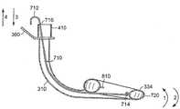
도 11은 본 발명에 따라 제조된 또 다른 후두 마스크 기도 장치(700)의 측단면도를 나타낸다. 본 발명에 따라 제조된 앞서 논의된 장치와 같이, 장치(700)는 기도튜브(310), 팽창가능한 커프(334), 손잡이(360) 및 후두개 지지 플랜지(810)를 포함한다. 장치(700)는 또한 봉(710)을 포함한다. 봉(710)은 근위부 말단(712)에서부터 원위부 말단(714)까지 뻗어있다. 근위부 말단(712)은 후크 모양으로 정의된다. 봉(710)은 기도튜브(310)의 연결부(410)를 지나 뻗어있어 후크 모양의 근위부 말단(712)이 상기 기도튜브(310)의 바깥쪽에 놓이게 된다. 상기 봉(710)의 원위부 말단(714)은 상기 후두개 지지 플랜지(810)에 부착되거나 매달리게 된다. 설명한 바와 같이, 봉(710)의 상기 원위부 말단(714)은 상기 장치(700)의 원위부 말단(720)에 가장 가까운 상기 플랜지(810)의 부분에 부착된다. 봉(710)은 또한 상기 근위부 말단(712) 근처의 가시적 표식 부호(716)도 규정한다. 봉(716)은 나일 론과 같은 유연성의 무탄력 물질로 제조될 수 있다. 봉(716)은 약 4 내지 5 밀리미터 너비 및 0.5 내지 1 밀리미터 두께의 일반적으로 평평한 막대로서 형성될 수 있다. 하기에 논의하겠지만, 봉(710)은 (1) 장치(700)를 환자에 삽입; (2) 장치(700)가 완전히 삽입된 형태로 적절하게 삽입된 것의 확인; 및 (3) 장치(700)를 환자에 삽입하는 동안 일어날 수 있는 문제의 탐지를 유리하게 용이하게 한다.11 shows a side cross-sectional view of another laryngeal mask airway device 700 made in accordance with the present invention. Like the devices discussed above made in accordance with the present invention, the device 700 includes an
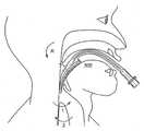
상기에서 논의한 바와 같이, 도 5 및 도 6은 완전히 삽입된 형태의 위치에 있는 후두 마스크 기도 장치를 나타낸다. 완전히 삽입된 형태의 장치와 같이 위치하는 것은 환자의 입으로 상기 장치의 원위부 말단을 삽입하는 것과 다음으로 상기 원위부 말단이 환자의 정상적으로 닫힌 식도 괄약근에 대항해서 치우칠 때까지 환자의 본래 기도를 통하여 원위부 말단을 밀어넣는 것과 관련된다. 도 12는 환자에 부분적으로 삽입된 후두 마스크 기도 장치를 나타낸다. 도 12에 일반적으로 나타낸 바와 같이, 삽입 동안, 상기 장치의 원위부 말단은 일반적으로 환자의 해부학적인 기도 통로를 따라갈 수 있도록, 그리고 특히 환자의 혀(800)의 뒤를 미끄러져 지나가도록 화살표 R로 나타낸 방향으로 일시적으로 구부러진다. 이런 방향으로 일시적으로 구부러진 후, 상기 장치는 상기 혀의 뒤를 지나 들어갈 때 다시 똑바르게 펴져 도 5 및 도 6에 전체적으로 도시된 형태를 추정할 수 있게 된다.As discussed above, FIGS. 5 and 6 show the laryngeal mask airway device in a fully inserted position. Positioning with the device in its fully inserted form inserts the distal end of the device into the patient's mouth and then distal distal end through the patient's original airway until the distal end is biased against the patient's normally closed esophageal sphincter. It is related to pushing. 12 shows a laryngeal mask airway device partially inserted into a patient. As generally shown in FIG. 12, during insertion, the distal end of the device is generally indicated by arrow R such that it can follow the patient's anatomical airway passages, and in particular slides behind the patient's
상기 후두 마스크 기도 장치가 비록 환자에 일반적으로 삽입하기가 단순할지라도(예를 들어, 기관 내 튜브와 비교하여), 삽입되는 동안에 문제가 생길 수 있다. 예를 들어, 식도 괄약근에 대항해서 안착되는 대신 상기 장치의 원위부 말단이 때때로 성문 개구부로 들어가 상기 장치가 환자의 기관으로 일부 뻗어있다. 또 한, 삽입되는 동안에 상기 장치의 원위부 말단이 화살표 1에 의해 또는 화살표 2에 의해 표시되는 방향으로 접힐 수 있고 다음으로 다시 펴지지 않아 상기 장치가 적당한 완전히 삽입된 형태에 이르지 못한다. 봉(710)은 이러한 바라지 않는 상황이 발생했을 때 탐지하도록 하며, 이러한 바라지 않는 상황이 일어나지 않도록 하며, 때때로 이러한 바라지 않는 상황을 바로 잡도록 할 수 있다.Although the laryngeal mask airway device is generally simple to insert into a patient (eg, compared to an endotracheal tube), problems may arise during insertion. For example, instead of being seated against the esophageal sphincter, the distal end of the device sometimes enters the glottal opening and the device extends partially into the patient's organ. In addition, during insertion the distal end of the device may be folded in the direction indicated by arrow 1 or by
장치(700)가 완전히 삽입된 형태임을 추정하게 할 수 있도록 상기 장치가 적절한 형상으로 있을 때, 상기 표식 부호(716)는 도 11에 나타낸 바와 같이 연결부(410)의 근위부 말단에 인접한다. 그러나, 만약 상기 장치가 접혀있거나 휘어져 있어 상기 장치의 원위부 말단(720)이 화살표 1에 의해 표시되는 방향으로 놓이면, 상기 표식 부호(716)는 더 이상 상기 연결부(410)의 근위부 말단에 인접하지 않을 것이고 대신 화살표 4로 표시되는 방향으로 상기 기도튜브의 외부에 놓일 것이다. 마찬가지로, 만약 상기 장치가 접혀있거나 휘어져 있어 상기 장치의 원위부 말단(720)이 화살표 2로 표시되는 방향으로 놓이면, 상기 표식 부호(716)는 상기 연결부(410)의 근위부 말단에 인접하지 않을 것이고 대신 화살표 3으로 표시되는 방향으로 상기 기도튜브 내로 빠지게 될 것이다. 이와 같이, 봉(710)의 상기 표식 부호(716)는 상기 장치(700)가 완전히 삽입된 형태임을 추정하게 할 수 있도록 적절한 위치에 있지 않을 때 탐지하도록 사용될 수 있다. 상기 표식 부호(716)의 이러한 용도는 후두 마스크 기도 장치의 삽입과 관련된 가장 일반적인 문제의 탐지를 할 수 있게 한다.When the device is in a suitable shape so as to allow the device 700 to be in its fully inserted form, the
상기 봉(710)을 장치(700)의 상태 또는 형상 탐지에 사용하는 것과 더불어, 상기 봉(710)은 장치(700)의 형상을 조절하는데 또한 사용될 수 있다. 상기 근위부 말단(712)은 화살표 3 및 4로 표시된 방향으로 기도튜브(310)에 상대적으로 조여져 밀리거나 당겨질 수 있다. 상기 근위부 말단(712)을 화살표 4로 표시되는 방향으로 당기는 것은 상기 장치의 원위부 말단(720)을 화살표 1로 표시되는 방향으로 움직이게 한다. 마찬가지로, 근위부 말단(712)을 화살표 3으로 표시되는 방향으로 미는 것은 상기 장치의 원위부 말단(720)을 화살표 2로 표시되는 방향으로 움직이게 한다. 상기 봉(710)의 이러한 움직임은 상기 장치가 환자에 삽입되는 것을 용이하게 할 수 있다. 예를 들어, 상기 봉을 화살표 4로 표시되는 방향으로 당기는 것은 상기 장치를 삽입하는 동안에 상기 장치의 원위부 말단을 환자의 혀의 뒤 주변으로 휘어지게 한다. 마찬가지로, 상기 봉을 화살표 3의 방향으로 미는 것은 상기 장치를 곧게 펴지게 할 수 있다. 만약 상기 봉을 당기거나 밀어서 상기 장치의 형상을 바로잡는 것이 불가능하다면, 상기 표식 부호(716)의 위치는 상기 장치(700)가 적절하게 삽입되지 않았고 상기 장치를 간단하게 환자로부터 꺼내어 다시 삽입할 수 있음을 나타낼 것이다.In addition to using the
상기에서 논의된 손잡이(360)의 다른 유리한 점에 덧붙여, 손잡이(360)는 봉(710)의 근위부 말단(712)을 조작하는 동안에 기도튜브(310)를 유지하기 위한 편리한 위치도 제공한다. 상기에서 논의된 바와 같이, 봉(710)의 상기 원위부 말단(714)은 상기 후두개 지지 플랜지(810)에 부착될 수 있다. 그러나, 봉(714)의 상기 원위부 말단은 대안적으로 상기 기도튜브(310) 자체에 부착될 수 있다. 이러한 실시 형태에서, 상기 봉(714)의 원위부 말단이 상기 기도튜브(310)의 원위부에 부 착되는 것이 대체로 유리하다. 일체형 튜브·뒷판부(450)의 단면을 나타내는 도 4E를 참조하면, 상기 부분(450)에는 새김눈(notch)(464) 및 홈(466)이 형성되어있다. 상기에서 미국특허 제 09/544,681호 및 제 10/138,806호 (변리사 도켓번호 LMA-3 및 LMA-12)에 해당하는 것으로 소개되어 논의된 바와 같이, 상기 새김눈(464) 및 홈(466)으로 정의된 상기 후두 마스크 기도 장치를 따라 기관 내부 튜브의 삽입을 용이하게 한다. 상기 새김눈(464) 및 홈(466)은 봉(710)이 상기 기도튜브 중앙 내에 있도록 하고 또 보(710)이 상기 기도튜브 내에서 횡방향으로 움직이지 않도록 봉(710)에 대한 안내 역할도 제공한다.In addition to the other advantages of the
상기 장치(700)는 손잡이(360), 후두개 지지 플랜지(810) 및 봉(710)을 포함하는 것으로 설명하였으나, 후두 마스크 기도 장치는 본 발명에 따라 상기 손잡이 및 플랜지를 갖거나 갖지 않는 것으로 제조될 수 있음을 알 수 있다.Although the device 700 has been described as including a
본 명세서에 개시된 본 발명의 범위를 벗어나는 일없이 어떤 변형도 상기 장치에 행할 수 있기 때문에, 상기 명세서의 설명 또는 첨부하는 도면에 나타낸 모든 내용은 예시일뿐 한정의 의미로 해석되는 것은 아니다.Since any modifications may be made to the apparatus without departing from the scope of the invention disclosed herein, not all details shown in the description of the specification or in the accompanying drawings are illustrative and are not to be construed as limiting.
Claims (22)
Translated fromKoreanApplications Claiming Priority (2)
| Application Number | Priority Date | Filing Date | Title |
|---|---|---|---|
| US10/657,418US7134431B2 (en) | 2003-09-08 | 2003-09-08 | Laryngeal mask airway device with position controlling tab |
| US10/657,418 | 2003-09-08 |
Publications (1)
| Publication Number | Publication Date |
|---|---|
| KR20060121861Atrue KR20060121861A (en) | 2006-11-29 |
Family
ID=34226544
Family Applications (1)
| Application Number | Title | Priority Date | Filing Date |
|---|---|---|---|
| KR1020067004744ACeasedKR20060121861A (en) | 2003-09-08 | 2004-09-01 | Laryngeal Mask Airway Device with Positioning Handle |
Country Status (18)
| Country | Link |
|---|---|
| US (1) | US7134431B2 (en) |
| EP (3) | EP2165727A3 (en) |
| JP (3) | JP4847865B2 (en) |
| KR (1) | KR20060121861A (en) |
| CN (2) | CN101822861A (en) |
| AT (1) | ATE464086T1 (en) |
| AU (2) | AU2004269901B2 (en) |
| BR (1) | BRPI0414202B1 (en) |
| CA (1) | CA2537957C (en) |
| DE (1) | DE602004026605D1 (en) |
| ES (1) | ES2356349T3 (en) |
| IL (1) | IL174083A0 (en) |
| MX (1) | MXPA06002628A (en) |
| PL (1) | PL379562A1 (en) |
| RU (1) | RU2379063C2 (en) |
| TW (1) | TW200520803A (en) |
| WO (1) | WO2005023351A1 (en) |
| ZA (1) | ZA200602658B (en) |
Families Citing this family (64)
| Publication number | Priority date | Publication date | Assignee | Title |
|---|---|---|---|---|
| US5878745A (en) | 1996-03-01 | 1999-03-09 | Brain; Archibald I.J. | Gastro-laryngeal mask |
| US7357845B2 (en)* | 1997-04-10 | 2008-04-15 | Cookgas, L.L.C. | Methods of making laryngeal masks |
| US8631796B2 (en) | 1997-04-10 | 2014-01-21 | Cookgas, L.L.C. | Laryngeal mask |
| US7331346B2 (en) | 1997-12-24 | 2008-02-19 | Indian Ocean Medical, Inc. | Monitoring and control for a laryngeal mask airway device |
| USD518572S1 (en)* | 2002-08-14 | 2006-04-04 | Muhammed Aslam Nasir | Laryngeal mask airway device |
| GB0218868D0 (en) | 2002-08-14 | 2002-09-25 | Nasir Muhammed A | Improved airway management device |
| WO2005016427A2 (en)* | 2003-08-14 | 2005-02-24 | Muhammed Aslam Nasir | Improved airway device |
| US7134431B2 (en)* | 2003-09-08 | 2006-11-14 | Indian Ocean Medical Inc. | Laryngeal mask airway device with position controlling tab |
| US7096868B2 (en)* | 2004-03-09 | 2006-08-29 | Nellcor Puritan Bennett Incorporated | Laryngeal airway device |
| USD518890S1 (en)* | 2004-06-24 | 2006-04-11 | Muhammed Aslam Nasir | Laryngeal mask airway device |
| GB0510951D0 (en) | 2005-05-27 | 2005-07-06 | Laryngeal Mask Company The Ltd | Laryngeal mask airway device |
| US20070023051A1 (en)* | 2005-07-30 | 2007-02-01 | Cook Daniel J | Inflatable airways with pressure monitoring devices |
| US7735489B2 (en)* | 2006-01-13 | 2010-06-15 | Olympus Medical Systems Corp. | Endotracheal tube, device for use in medical procedure through natural opening and medical procedure through natural opening |
| USD615188S1 (en) | 2006-02-14 | 2010-05-04 | Intersurgical Uab | Airway device |
| US7900632B2 (en) | 2006-08-18 | 2011-03-08 | Cookgas, L.L.C. | Laryngeal mask with esophageal blocker and bite block |
| US7784464B2 (en) | 2006-09-15 | 2010-08-31 | Cookgas, Llc | Laryngeal mask |
| US7780900B2 (en) | 2006-09-15 | 2010-08-24 | Cookgas, Llc | Methods of forming a laryngeal mask |
| USD611138S1 (en)* | 2006-12-21 | 2010-03-02 | Intersurgical Uab | Laryngeal mask airway device |
| USD567367S1 (en)* | 2007-03-14 | 2008-04-22 | Mongeon Douglas R | Stylet |
| US8800566B2 (en)* | 2007-04-16 | 2014-08-12 | Ecolab Usa Inc. | Airway devices, tube securing devices, and methods of making and using the same |
| US7934502B2 (en) | 2007-05-11 | 2011-05-03 | Cookgas, Llc | Self-pressurizing supraglottic airway |
| GB0719054D0 (en)* | 2007-09-29 | 2007-11-07 | Nasir Muhammed A | Airway device |
| GB2456747A (en)* | 2007-10-12 | 2009-07-29 | Laryngeal Mask Co Ltd | Laryngeal mask airway device with a parylene coating |
| GB2454199A (en)* | 2007-10-30 | 2009-05-06 | Laryngeal Mask Co Ltd | Laryngeal mask with tape tab |
| GB0810169D0 (en)* | 2008-06-04 | 2008-07-09 | Cosmeplast Ets | Improvements relating to respiratory interface devices |
| WO2009149555A1 (en)* | 2008-06-11 | 2009-12-17 | Governors Of The University Of Alberta | Cricothyrotomy device |
| USD618788S1 (en)* | 2008-11-27 | 2010-06-29 | Deltona Innovations Ag | Laryngeal mask |
| GB0903654D0 (en) | 2009-03-03 | 2009-04-15 | Laryngeal Mask Company The Ltd | Artificial airway device |
| WO2011003135A1 (en) | 2009-07-06 | 2011-01-13 | Ultimate Medical Pty. Ltd. | Artificial airway |
| USD665495S1 (en) | 2009-07-14 | 2012-08-14 | Muhammed Aslam Nasir | Medical device |
| WO2011017756A1 (en) | 2009-08-13 | 2011-02-17 | Ultimate Medical Pty. Ltd. | Pressure indicator |
| GB201010647D0 (en) | 2010-06-24 | 2010-08-11 | Docsinnovent Ltd | Stopper device |
| EP2608834A4 (en)* | 2010-08-23 | 2015-04-15 | Kanag Baska | Laryngeal mask with enhanced insertion |
| GB201016562D0 (en) | 2010-10-01 | 2010-11-17 | Laryngeal Mask Company The Ltd | Artificial airway device |
| EP2627387B1 (en) | 2010-10-15 | 2018-08-15 | Teleflex Life Sciences Unlimited Company | Artificial airway device |
| JP6242687B2 (en) | 2011-02-02 | 2017-12-06 | ウメダス、リミテッドUmedaes Limited | Improved artificial airway |
| USD693920S1 (en) | 2011-06-08 | 2013-11-19 | Intersurgical Ag | Airway device |
| USD665254S1 (en) | 2011-06-08 | 2012-08-14 | Intersurgical Ag | Airway device packaging |
| USD688787S1 (en) | 2011-06-08 | 2013-08-27 | Intersurgical Ag | Airway device cap and strap holder |
| CA144804S (en)* | 2011-09-07 | 2012-12-20 | Laryngeal Mask Co Ltd | Laryngeal mask |
| USD712244S1 (en) | 2011-09-23 | 2014-09-02 | Intersurgical Ag | Medical device package |
| USD716937S1 (en)* | 2011-10-18 | 2014-11-04 | The Laryngeal Mask Company Limited | Laryngeal mask airway device |
| GB201120628D0 (en) | 2011-11-30 | 2012-01-11 | Laryngeal Mask Company The Ltd | Endoscopy device |
| GB201201438D0 (en) | 2012-01-27 | 2012-03-14 | Docsinnovent Ltd | Improved stopper device |
| USD761952S1 (en) | 2012-07-27 | 2016-07-19 | Docsinnovent Limited | Airway device |
| CH706616A2 (en)* | 2012-06-04 | 2013-12-13 | Deltona Innovations Ag | Laryngeal mask with a supraglottic tube. |
| GB2546167B (en) | 2013-12-17 | 2018-02-28 | Aslam Nasir Muhammed | Intubating Airway Device |
| DK177742B1 (en)* | 2014-01-24 | 2014-05-19 | Ambu As | A laryngeal mask with a bite absorbing connector |
| SG2014011720A (en) | 2014-02-10 | 2015-09-29 | Craig Wight Ronald | An airway management device and method of manufacture |
| CN104841047A (en)* | 2015-06-03 | 2015-08-19 | 田鸣 | Novel laryngeal mask |
| USD1051359S1 (en) | 2015-06-15 | 2024-11-12 | Intersurgical Ag | Airway device |
| USD842456S1 (en) | 2015-12-15 | 2019-03-05 | Intersurgical Ag | Airway device |
| AU2017282981A1 (en)* | 2016-03-31 | 2018-10-18 | Teleflex Life Sciences Llc | Fixation device for a laryngeal mask |
| CN111437062B (en)* | 2016-04-08 | 2022-12-13 | 阿普力特医疗股份有限公司 | Implantable system for the treatment of glottic insufficiency in patients |
| GB201617855D0 (en) | 2016-10-21 | 2016-12-07 | Teleflex Life Sciences Unlimited Co | Artificial airway device |
| AU201714823S (en) | 2017-02-27 | 2017-10-12 | Teleflex Life Sciences Unlimited Co | Laryngeal mask airway device |
| US10213567B1 (en) | 2017-11-08 | 2019-02-26 | Shan Theventhiran | Easily removable intubating LMA |
| USD884155S1 (en)* | 2017-11-10 | 2020-05-12 | Consumables Medical Pacific Industries Limited | Laryngeal mask |
| GB201720733D0 (en) | 2017-12-13 | 2018-01-24 | Ashkal Development Ltd | Airway device |
| US10596339B2 (en)* | 2018-05-21 | 2020-03-24 | Sridhar R. Musuku | Intubation devices and methods of use |
| JP1649726S (en) | 2019-01-18 | 2020-01-14 | ||
| CN116547029A (en)* | 2019-06-24 | 2023-08-04 | 气道医疗创新有限公司 | Laryngeal mask airway intubation guide and method |
| USD1025348S1 (en) | 2020-04-16 | 2024-04-30 | Intersurgical Ag | Airway device |
| TWI841457B (en)* | 2023-07-25 | 2024-05-01 | 陳天生 | Nasopharyngeal airway |
Family Cites Families (95)
| Publication number | Priority date | Publication date | Assignee | Title |
|---|---|---|---|---|
| US2862498A (en)* | 1957-06-14 | 1958-12-02 | Don J Weekes | Endotracheal tube |
| US3554673A (en)* | 1969-01-31 | 1971-01-12 | Sage Instr Inc | Syringe pump |
| US4231365A (en)* | 1978-01-30 | 1980-11-04 | Scarberry Eugene N | Emergency resuscitation apparatus |
| DE3037708C2 (en)* | 1980-10-06 | 1983-10-06 | Willy Ruesch Gmbh & Co Kg, 7053 Kernen | Instrument for inserting a tube into a patient's windpipe |
| US4329984A (en)* | 1981-01-13 | 1982-05-18 | David Kervin | Endotracheal-tube stabilizer |
| GB2111394B (en)* | 1981-12-16 | 1985-09-11 | Archibald Ian Jeremy Brain | Artificial airway device |
| US4553540A (en)* | 1983-08-16 | 1985-11-19 | Straith Richard E | Airway |
| SU1409282A1 (en)* | 1985-08-25 | 1988-07-15 | Ростовский научно-исследовательский онкологический институт | Device for fixing endotracheal tube |
| US4793327A (en)* | 1986-01-21 | 1988-12-27 | Frankel Alfred R | Device for opening a patient's airway during automatic intubation of the trachea |
| SU1595528A1 (en)* | 1987-04-10 | 1990-09-30 | Н,И. Иващенко и Л.Д. Ахмов | Fixator for incubation tube |
| GB2205499B (en) | 1987-06-05 | 1991-01-16 | Archibald Ian Jeremy Brain | Artificial airway device |
| US4872483A (en)* | 1987-12-31 | 1989-10-10 | International Medical Products, Inc. | Conveniently hand held self-contained electronic manometer and pressure modulating device |
| US4832019A (en)* | 1988-03-16 | 1989-05-23 | Burton Weinstein | Endotracheal tube holder |
| US4953547A (en)* | 1989-01-26 | 1990-09-04 | Poole Jr Samuel E | Drug administering endotracheal respiration systems |
| GB2229367A (en)* | 1989-03-22 | 1990-09-26 | Archibald Ian Jeremy Brain | Artificial airway device |
| US5169379A (en) | 1989-06-14 | 1992-12-08 | L-Vad Technology | In-series ventricular assist system and method of controlling same |
| EP0490979B1 (en) | 1989-09-08 | 1996-11-13 | Boston Scientific Corporation | Physiologic low stress angioplasty |
| US5038766A (en) | 1989-11-08 | 1991-08-13 | Parker Jeffrey D | Blind orolaryngeal and oroesophageal guiding and aiming device |
| US5174283A (en)* | 1989-11-08 | 1992-12-29 | Parker Jeffrey D | Blind orolaryngeal and oroesophageal guiding and aiming device |
| GB9003857D0 (en) | 1990-02-21 | 1990-04-18 | Smiths Industries Plc | Medico-surgical tube assemblies |
| GB9102821D0 (en) | 1991-02-11 | 1991-03-27 | Brain Archibald Ian Jeremy | An intubating laryngeal mask airway |
| US5339808A (en)* | 1991-04-02 | 1994-08-23 | Don Michael T Anthony | Endotracheal-esophageal intubation devices |
| GB9119703D0 (en)* | 1991-09-14 | 1991-10-30 | Dingley John | Medico-surgical device |
| MX9301163A (en)* | 1992-03-05 | 1994-07-29 | Brain Archibald Ian Jeremy | LARINGEA MASK AND METHOD FOR ITS MANUFACTURE. |
| US5241956A (en)* | 1992-05-21 | 1993-09-07 | Brain Archibald Ian Jeremy | Laryngeal mask airway with concentric drainage of oesophagus discharge |
| US5249571A (en)* | 1992-05-21 | 1993-10-05 | Brain Archibald Ian Jeremy | Laryngeal clamp airway |
| EP0580385B1 (en) | 1992-07-21 | 1996-05-08 | Archibald Ian Jeremy Dr. Brain | Laryngeal mask incorporating a reflectance oximeter |
| GB9215455D0 (en)* | 1992-07-21 | 1992-09-02 | Brain Archibald Ian Jeremy | A laryngeal mask airway adapted to carry a reflecting-type oximeter |
| US5297547A (en)* | 1992-07-30 | 1994-03-29 | Brain Archibald Ian Jeremy | Laryngeal mask construction |
| US5355879A (en)* | 1992-09-28 | 1994-10-18 | Brain Archibald Ian Jeremy | Laryngeal-mask construction |
| US5443063A (en)* | 1993-08-31 | 1995-08-22 | The Johns Hopkins University | Cuffed oro-pharyngeal airway |
| US5599301A (en)* | 1993-11-22 | 1997-02-04 | Advanced Cardiovascular Systems, Inc. | Motor control system for an automatic catheter inflation system |
| US5443060A (en)* | 1994-01-05 | 1995-08-22 | Novametrix Medical Systems, Inc. | System for supporting endotracheal tubes in pediatric patients and method of using same |
| GB2285765B (en)* | 1994-01-12 | 1997-10-29 | Archibald Ian Jeremy Brain | Forming tool for use with a laryngeal mask |
| US5529582A (en)* | 1994-02-01 | 1996-06-25 | Fukuhara; Tomio | Apparatus for inserting laryngeal mask |
| JP3782123B2 (en) | 1994-05-31 | 2006-06-07 | 住友ベークライト株式会社 | Pharyngeal airway |
| GB9411215D0 (en) | 1994-06-04 | 1994-07-27 | Brain Archibald Ian Jeremy | A fibreoptic intubating laryngeal mask airway |
| US5569219A (en)* | 1994-09-13 | 1996-10-29 | Hakki; A-Hamid | Collapsible catheter |
| GB9422224D0 (en)* | 1994-11-03 | 1994-12-21 | Brain Archibald Ian Jeremy | A laryngeal mask airway device modified to detect and/or stimulate mescle or nerve activity |
| US5477851A (en)* | 1995-01-26 | 1995-12-26 | Callaghan; Eric B. | Laryngeal mask assembly and method for removing same |
| GB9504657D0 (en)* | 1995-03-08 | 1995-04-26 | Neil Michael J O | An improved artificial airway device |
| GB9505134D0 (en) | 1995-03-14 | 1995-05-03 | Smiths Industries Plc | Laryngeal mask airways |
| GB9505399D0 (en)* | 1995-03-17 | 1995-05-03 | Smiths Industries Plc | Medico-surgical devices |
| GB9513860D0 (en)* | 1995-07-07 | 1995-09-06 | Smiths Industries Plc | Securing devices |
| MY115052A (en) | 1995-10-03 | 2003-03-31 | Archibald Ian Jeremy Brain | Laryngeal mask airway incorporating an epiglottic elevating mechanism |
| MY138519A (en) | 1995-10-03 | 2009-06-30 | Indian Ocean Medical Inc | Artificial airway device |
| US5791341A (en)* | 1995-12-19 | 1998-08-11 | Bullard; James Roger | Oropharyngeal stent with laryngeal aditus shield and nasal airway with laryngeal aditus shield |
| US6860264B2 (en)* | 1996-02-26 | 2005-03-01 | Evergreen Medical Incorporated | Method and apparatus for endotracheal intubation using a light wand and curved guide |
| US5878745A (en)* | 1996-03-01 | 1999-03-09 | Brain; Archibald I.J. | Gastro-laryngeal mask |
| GB9606012D0 (en) | 1996-03-22 | 1996-05-22 | Brain Archibald Ian Jeremy | Laryngeal mask with gastric-drainage feature |
| US5623924A (en)* | 1996-03-29 | 1997-04-29 | Lindenman; Tammy S. | Apparatus and method for retaining an endotracheal tube |
| US5623921A (en)* | 1996-04-10 | 1997-04-29 | Kinsinger; J. William | Laryngeal mask airway and method for its use |
| US5682880A (en)* | 1996-07-26 | 1997-11-04 | Brain; Archibald Ian Jeremy | Laryngeal-mask airway with guide element, stiffener, and fiberoptic access |
| GB2317342B (en) | 1996-09-18 | 2000-03-29 | Smiths Industries Plc | Laryngeal mask assemblies |
| GB9619432D0 (en)* | 1996-09-18 | 1996-10-30 | Smiths Industries Plc | Laryngeal mask assemblies |
| GB2317830B (en) | 1996-10-03 | 2000-03-29 | Smiths Industries Plc | Laryngeal mask airways and their manufacture |
| GB9620609D0 (en) | 1996-10-03 | 1996-11-20 | Smiths Industries Plc | Laryngeal mask airways and their manufacture |
| US6070581A (en) | 1996-10-16 | 2000-06-06 | Augustine Medical, Inc. | Laryngeal airway device |
| US6427686B2 (en)* | 1996-10-16 | 2002-08-06 | Augustine Medical, Inc. | Airway device with provision for coupling to an introducer |
| GB2318735B (en) | 1996-11-02 | 2000-04-19 | Smiths Industries Plc | Laryngeal mask airways and their manufacture |
| GB9622880D0 (en)* | 1996-11-02 | 1997-01-08 | Smiths Industries Plc | Laryngeal mask airways and thier manufacture |
| GB2319478B (en) | 1996-11-19 | 2000-04-19 | Smiths Industries Plc | Laryngeal mask airways and their manufacture |
| GB9624029D0 (en) | 1996-11-19 | 1997-01-08 | Smiths Industries Ltd | Laryngeal mask airways and their manufacture |
| GB9702337D0 (en) | 1997-02-05 | 1997-03-26 | Smiths Industries Plc | Laryngeal mask airways and their manufacture |
| US5743254A (en)* | 1997-03-18 | 1998-04-28 | Parker Medical Limited Partnership | Orotracheal intubation guide |
| GB9705585D0 (en) | 1997-03-18 | 1997-05-07 | Smiths Industries Plc | Laryngeal mask assemlies |
| GB2323289B (en) | 1997-03-18 | 2001-02-14 | Smiths Industries Plc | Laryngeal mask assemblies |
| GB9705537D0 (en)* | 1997-03-18 | 1997-05-07 | Smiths Industries Plc | Laryngeal mask assemblies |
| GB9705586D0 (en) | 1997-03-18 | 1997-05-07 | Smiths Industries Plc | Laryngeal mask assemblies |
| US5937860A (en)* | 1997-04-10 | 1999-08-17 | Cook; Daniel J. | Laryngeal mask |
| GB9708568D0 (en)* | 1997-04-29 | 1997-06-18 | Smiths Industries Ltd | Cuffed medico-surgical tubes |
| US5988167A (en)* | 1997-05-02 | 1999-11-23 | Kamen; Jack M. | Foam cuff for laryngeal mask airway |
| GB9709297D0 (en) | 1997-05-03 | 1997-06-25 | Smiths Industries Plc | Laryngeal mask assemblies |
| GB9710645D0 (en) | 1997-05-22 | 1997-07-16 | Smiths Industries Plc | Cuffed tube assemblies |
| JPH10323391A (en) | 1997-05-23 | 1998-12-08 | Aoki Shigeru | Stable laryngeal mask |
| US5850832A (en)* | 1997-06-23 | 1998-12-22 | Chu; Kyo Y. | Laryngeal mask airway insertion guide |
| US6079409A (en)* | 1997-07-25 | 2000-06-27 | Brain; Archibald Ian Jeremy | Intubating laryngeal mask |
| GB9716287D0 (en) | 1997-08-02 | 1997-10-08 | Nimmo Garry H | Apparatus for shaping a laryngeal mask |
| GB9721840D0 (en) | 1997-10-16 | 1997-12-17 | Smiths Industries Plc | Laryngeal mask assemblies |
| GB9725389D0 (en) | 1997-12-02 | 1998-01-28 | Smiths Industries Plc | Laryngeal mask assemblies |
| US6003510A (en)* | 1997-12-04 | 1999-12-21 | Anunta; Boonchuay | Hand tool for introducing a laryngeal mask |
| GB9803199D0 (en)* | 1998-02-17 | 1998-04-08 | Smiths Industries Plc | Laryngeal mask airways and their manufacture |
| WO2000023135A1 (en) | 1998-10-19 | 2000-04-27 | Dimitriou K Vasilios | Device for guided tracheal intubation |
| WO2000022985A1 (en) | 1998-10-22 | 2000-04-27 | Children's Hospital, Inc. | Apparatus for controlled ventilation of a patient |
| US6119695A (en)* | 1998-11-25 | 2000-09-19 | Augustine Medical, Inc. | Airway device with provision for lateral alignment, depth positioning, and retention in an airway |
| US6257236B1 (en)* | 1999-02-23 | 2001-07-10 | Edward P Dutkiewicz | Intubation device |
| CA2813505C (en)* | 1999-04-09 | 2015-06-23 | The Laryngeal Mask Company Limited | Disposable laryngeal mask airway device |
| US6390093B1 (en) | 1999-04-14 | 2002-05-21 | Vital Signs, Inc. | Artificial airway device and method of its use |
| CA2468108A1 (en)* | 1999-09-27 | 2003-06-05 | Merlyn Associates, Inc. | Endotracheal tube with tip directional control and position preserving mechanism |
| GB0002805D0 (en) | 2000-02-08 | 2000-03-29 | Smiths Industries Plc | Masks and their manufacture |
| US6718970B2 (en)* | 2001-07-25 | 2004-04-13 | Joseph A. Sniadach | Intubation system and methods of use thereof |
| US7159589B2 (en)* | 2001-08-23 | 2007-01-09 | Indian Ocean Medical Inc. | Disposable laryngeal mask airway device |
| US6725862B2 (en)* | 2001-08-24 | 2004-04-27 | Naum Klinberg | Tracheostomy tube apparatus for noninvasive suctioning |
| GB2383755B (en)* | 2002-01-04 | 2004-02-25 | Future Top Medical Environment | Obturator for use with a laryngeal mask airway |
| US7134431B2 (en)* | 2003-09-08 | 2006-11-14 | Indian Ocean Medical Inc. | Laryngeal mask airway device with position controlling tab |
- 2003
- 2003-09-08USUS10/657,418patent/US7134431B2/ennot_activeExpired - Lifetime
- 2004
- 2004-09-01EPEP10150122.9Apatent/EP2165727A3/ennot_activeWithdrawn
- 2004-09-01PLPL379562Apatent/PL379562A1/ennot_activeApplication Discontinuation
- 2004-09-01AUAU2004269901Apatent/AU2004269901B2/ennot_activeExpired
- 2004-09-01EPEP04764731Apatent/EP1663364B1/ennot_activeExpired - Lifetime
- 2004-09-01JPJP2006525706Apatent/JP4847865B2/ennot_activeExpired - Lifetime
- 2004-09-01EPEP10150123.7Apatent/EP2165728A3/ennot_activeWithdrawn
- 2004-09-01CNCN200910207908Apatent/CN101822861A/enactivePending
- 2004-09-01MXMXPA06002628Apatent/MXPA06002628A/enactiveIP Right Grant
- 2004-09-01RURU2006110572/14Apatent/RU2379063C2/ennot_activeIP Right Cessation
- 2004-09-01ATAT04764731Tpatent/ATE464086T1/ennot_activeIP Right Cessation
- 2004-09-01WOPCT/EP2004/009772patent/WO2005023351A1/enactiveApplication Filing
- 2004-09-01BRBRPI0414202-0Apatent/BRPI0414202B1/ennot_activeIP Right Cessation
- 2004-09-01KRKR1020067004744Apatent/KR20060121861A/ennot_activeCeased
- 2004-09-01DEDE602004026605Tpatent/DE602004026605D1/ennot_activeExpired - Lifetime
- 2004-09-01CNCNB2004800257797Apatent/CN100566772C/ennot_activeExpired - Lifetime
- 2004-09-01CACA2537957Apatent/CA2537957C/ennot_activeExpired - Lifetime
- 2004-09-01ESES04764731Tpatent/ES2356349T3/ennot_activeExpired - Lifetime
- 2004-09-02TWTW093126512Apatent/TW200520803A/enunknown
- 2006
- 2006-03-02ILIL174083Apatent/IL174083A0/enunknown
- 2006-03-31ZAZA200602658Apatent/ZA200602658B/enunknown
- 2010
- 2010-01-14AUAU2010200155Apatent/AU2010200155C1/ennot_activeCeased
- 2010-03-15JPJP2010057929Apatent/JP5054144B2/ennot_activeExpired - Fee Related
- 2010-03-15JPJP2010057930Apatent/JP5054145B2/ennot_activeExpired - Fee Related
Also Published As
Similar Documents
| Publication | Publication Date | Title |
|---|---|---|
| KR20060121861A (en) | Laryngeal Mask Airway Device with Positioning Handle | |
| EP1587567B1 (en) | Laryngeal mask airway device | |
| US6196224B1 (en) | Perilaryngeal oral airway | |
| US7040312B2 (en) | Perilaryngeal oral airway with flexible tip guide | |
| AU2012216794B2 (en) | Laryngeal mask airway device with position controlling tab |
Legal Events
| Date | Code | Title | Description |
|---|---|---|---|
| PA0105 | International application | Patent event date:20060308 Patent event code:PA01051R01D Comment text:International Patent Application | |
| PG1501 | Laying open of application | ||
| A201 | Request for examination | ||
| PA0201 | Request for examination | Patent event code:PA02012R01D Patent event date:20080926 Comment text:Request for Examination of Application | |
| E902 | Notification of reason for refusal | ||
| PE0902 | Notice of grounds for rejection | Comment text:Notification of reason for refusal Patent event date:20100928 Patent event code:PE09021S01D | |
| E601 | Decision to refuse application | ||
| PE0601 | Decision on rejection of patent | Patent event date:20101213 Comment text:Decision to Refuse Application Patent event code:PE06012S01D Patent event date:20100928 Comment text:Notification of reason for refusal Patent event code:PE06011S01I |