KR20060119924A - Linear motor controller - Google Patents
Linear motor controllerDownload PDFInfo
- Publication number
- KR20060119924A KR20060119924AKR1020067004322AKR20067004322AKR20060119924AKR 20060119924 AKR20060119924 AKR 20060119924AKR 1020067004322 AKR1020067004322 AKR 1020067004322AKR 20067004322 AKR20067004322 AKR 20067004322AKR 20060119924 AKR20060119924 AKR 20060119924A
- Authority
- KR
- South Korea
- Prior art keywords
- piston
- period
- compression stroke
- stroke
- expansion stroke
- Prior art date
- Legal status (The legal status is an assumption and is not a legal conclusion. Google has not performed a legal analysis and makes no representation as to the accuracy of the status listed.)
- Withdrawn
Links
Images


Classifications
- F—MECHANICAL ENGINEERING; LIGHTING; HEATING; WEAPONS; BLASTING
- F04—POSITIVE - DISPLACEMENT MACHINES FOR LIQUIDS; PUMPS FOR LIQUIDS OR ELASTIC FLUIDS
- F04B—POSITIVE-DISPLACEMENT MACHINES FOR LIQUIDS; PUMPS
- F04B35/00—Piston pumps specially adapted for elastic fluids and characterised by the driving means to their working members, or by combination with, or adaptation to, specific driving engines or motors, not otherwise provided for
- F04B35/04—Piston pumps specially adapted for elastic fluids and characterised by the driving means to their working members, or by combination with, or adaptation to, specific driving engines or motors, not otherwise provided for the means being electric
- F04B35/045—Piston pumps specially adapted for elastic fluids and characterised by the driving means to their working members, or by combination with, or adaptation to, specific driving engines or motors, not otherwise provided for the means being electric using solenoids
- F—MECHANICAL ENGINEERING; LIGHTING; HEATING; WEAPONS; BLASTING
- F04—POSITIVE - DISPLACEMENT MACHINES FOR LIQUIDS; PUMPS FOR LIQUIDS OR ELASTIC FLUIDS
- F04B—POSITIVE-DISPLACEMENT MACHINES FOR LIQUIDS; PUMPS
- F04B39/00—Component parts, details, or accessories, of pumps or pumping systems specially adapted for elastic fluids, not otherwise provided for in, or of interest apart from, groups F04B25/00 - F04B37/00
- F04B39/0005—Component parts, details, or accessories, of pumps or pumping systems specially adapted for elastic fluids, not otherwise provided for in, or of interest apart from, groups F04B25/00 - F04B37/00 adaptations of pistons
- F—MECHANICAL ENGINEERING; LIGHTING; HEATING; WEAPONS; BLASTING
- F04—POSITIVE - DISPLACEMENT MACHINES FOR LIQUIDS; PUMPS FOR LIQUIDS OR ELASTIC FLUIDS
- F04B—POSITIVE-DISPLACEMENT MACHINES FOR LIQUIDS; PUMPS
- F04B39/00—Component parts, details, or accessories, of pumps or pumping systems specially adapted for elastic fluids, not otherwise provided for in, or of interest apart from, groups F04B25/00 - F04B37/00
- F04B39/12—Casings; Cylinders; Cylinder heads; Fluid connections
- F—MECHANICAL ENGINEERING; LIGHTING; HEATING; WEAPONS; BLASTING
- F04—POSITIVE - DISPLACEMENT MACHINES FOR LIQUIDS; PUMPS FOR LIQUIDS OR ELASTIC FLUIDS
- F04B—POSITIVE-DISPLACEMENT MACHINES FOR LIQUIDS; PUMPS
- F04B49/00—Control, e.g. of pump delivery, or pump pressure of, or safety measures for, machines, pumps, or pumping installations, not otherwise provided for, or of interest apart from, groups F04B1/00 - F04B47/00
- F04B49/06—Control using electricity
- F—MECHANICAL ENGINEERING; LIGHTING; HEATING; WEAPONS; BLASTING
- F04—POSITIVE - DISPLACEMENT MACHINES FOR LIQUIDS; PUMPS FOR LIQUIDS OR ELASTIC FLUIDS
- F04B—POSITIVE-DISPLACEMENT MACHINES FOR LIQUIDS; PUMPS
- F04B49/00—Control, e.g. of pump delivery, or pump pressure of, or safety measures for, machines, pumps, or pumping installations, not otherwise provided for, or of interest apart from, groups F04B1/00 - F04B47/00
- F04B49/12—Control, e.g. of pump delivery, or pump pressure of, or safety measures for, machines, pumps, or pumping installations, not otherwise provided for, or of interest apart from, groups F04B1/00 - F04B47/00 by varying the length of stroke of the working members
- H—ELECTRICITY
- H02—GENERATION; CONVERSION OR DISTRIBUTION OF ELECTRIC POWER
- H02P—CONTROL OR REGULATION OF ELECTRIC MOTORS, ELECTRIC GENERATORS OR DYNAMO-ELECTRIC CONVERTERS; CONTROLLING TRANSFORMERS, REACTORS OR CHOKE COILS
- H02P25/00—Arrangements or methods for the control of AC motors characterised by the kind of AC motor or by structural details
- H02P25/02—Arrangements or methods for the control of AC motors characterised by the kind of AC motor or by structural details characterised by the kind of motor
- H02P25/06—Linear motors
- F—MECHANICAL ENGINEERING; LIGHTING; HEATING; WEAPONS; BLASTING
- F04—POSITIVE - DISPLACEMENT MACHINES FOR LIQUIDS; PUMPS FOR LIQUIDS OR ELASTIC FLUIDS
- F04B—POSITIVE-DISPLACEMENT MACHINES FOR LIQUIDS; PUMPS
- F04B2203/00—Motor parameters
- F04B2203/04—Motor parameters of linear electric motors
- F04B2203/0401—Current
- F—MECHANICAL ENGINEERING; LIGHTING; HEATING; WEAPONS; BLASTING
- F04—POSITIVE - DISPLACEMENT MACHINES FOR LIQUIDS; PUMPS FOR LIQUIDS OR ELASTIC FLUIDS
- F04B—POSITIVE-DISPLACEMENT MACHINES FOR LIQUIDS; PUMPS
- F04B2203/00—Motor parameters
- F04B2203/04—Motor parameters of linear electric motors
- F04B2203/0402—Voltage
- F—MECHANICAL ENGINEERING; LIGHTING; HEATING; WEAPONS; BLASTING
- F04—POSITIVE - DISPLACEMENT MACHINES FOR LIQUIDS; PUMPS FOR LIQUIDS OR ELASTIC FLUIDS
- F04B—POSITIVE-DISPLACEMENT MACHINES FOR LIQUIDS; PUMPS
- F04B2207/00—External parameters
- F04B2207/04—Settings
- F04B2207/046—Settings of length of piston stroke
Landscapes
- Engineering & Computer Science (AREA)
- Mechanical Engineering (AREA)
- General Engineering & Computer Science (AREA)
- Power Engineering (AREA)
- Compressors, Vaccum Pumps And Other Relevant Systems (AREA)
- Control Of Positive-Displacement Pumps (AREA)
- Reciprocating, Oscillating Or Vibrating Motors (AREA)
- Control Of Linear Motors (AREA)
Abstract
Translated fromKoreanDescription
Translated fromKorean본 발명은 압축기를 구동하기 위해 사용되는 리니어 모터용 컨트롤러에 관한 것이며, 제한하는 것은 아니지만 특히 냉동 압축기를 구동하기 위해 사용되는 리니어 모터용 컨트롤러에 관한 것이다.The present invention relates to a controller for a linear motor used to drive a compressor, but not particularly limited to a controller for a linear motor used to drive a refrigeration compressor.
리니어 압축기는 가동 코일 또는 가동 자석에 대하여 작동하며 압축기에서와 같이 피스톤에 연결되었을 때 크랭크샤프트를 채용하는 일반적인 압축기와 달리 스트로크 진폭이 고정된 것이 아니기 때문에 스트로크 진폭에 대한 엄격한 제어가 필요하다. 압축되는 유체의 상태에 대한 과도한 모터 파워의 적용은 그 안에 피스톤이 배치되는 실린더 헤드와 피스톤 충돌을 초래할 수 있다.Linear compressors operate on movable coils or movable magnets and require strict control over stroke amplitude because the stroke amplitude is not fixed, unlike a conventional compressor that employs a crankshaft when connected to a piston as in a compressor. The application of excessive motor power to the state of the fluid being compressed can result in piston collision with the cylinder head in which the piston is placed.
본 출원인은 국제특허출원공보 WO 00/79671에서 압축기에 들어가는 냉매의 특성의 함수로서 모터의 출력을 제한하는 자유 피스톤 압축기용 제어 시스템을 제안하였다. 그러나, 몇몇 자유 피스톤 냉동 시스템에서는 실제 피스톤 충돌을 검출하고 그 다음에 응답하여 모터 파워를 감소시키는 것이 유용할 수 있다. 이러한 전략은 어떤 이유로 과도한 모터 파워가 발생되었을 때 순수하게 압축기 손상을 방지하기 위하여 사용되거나 또는 높은 체적 효율을 보장하는 방식으로 사용될 수 있다. 특히, 높은 체적 효율을 보장하는 것과 관련하여, 최소 헤드 클리어런스 체적 으로 피스톤이 작동하는 것을 보장하기 위하여 압축기는 피스톤 충돌을 일으키는 것으로 확인된 것보다 약간 작게 설정된 파워로 구동될 수 있다. 헤드 클리어런스 체적을 최소화하는 것은 제적 효율의 증가로 이어진다.The applicant has proposed a control system for a free piston compressor that limits the output of the motor as a function of the properties of the refrigerant entering the compressor in WO 00/79671. However, in some free piston refrigeration systems it may be useful to detect the actual piston collision and then reduce the motor power in response. This strategy can be used purely to prevent compressor damage when excessive motor power is generated for some reason, or in a way that ensures high volumetric efficiency. In particular, with regard to ensuring high volumetric efficiency, the compressor can be driven with a power set slightly less than that which has been found to cause piston collisions in order to ensure that the piston operates with a minimum head clearance volume. Minimizing the head clearance volume leads to an increase in the removal efficiency.
국제특허출원공보 WO 03/44365에서는 피스톤 충돌이 발생할 때 피스톤 충돌을 검출하기 위한 시스템을 제안하였다. 이 시스템은 충돌이 발생한 것을 나타내는 절반 주기 시간에서의 급격한 감소와 함께 절반 주기 시간을 모니터링하는 것을 포함한다. 리니어 모터에 대한 입력 파워의 후속적인 감소는 헤드와 충돌하지 않고 높은 체적 효율의 상태에서 압축기를 가동한다.International Patent Application WO 03/44365 proposes a system for detecting a piston collision when a piston collision occurs. The system includes monitoring half cycle time with a sharp decrease in half cycle time indicating that a collision has occurred. Subsequent reduction in input power for the linear motor runs the compressor in a state of high volumetric efficiency without colliding with the head.
그러나, WO 03/44365에 개시된 제어 전략은 압축기의 장기간 성능에 치명적인 실제적인 충돌을 필요로 한다. 게다가, 충돌없이 효율적인 작동을 보장하기 위하여 얼마나 구동 전류를 감소시킬지를 결정하는 것이 어렵다. 충돌의 위험을 낮추기 위하여 지나치게 신중한 조절이 이루어진다.However, the control strategy disclosed in WO 03/44365 requires a practical collision which is fatal to the long term performance of the compressor. In addition, it is difficult to determine how much drive current will be reduced to ensure efficient operation without collisions. Too much careful adjustments are made to lower the risk of a collision.
본 발명의 목적은 이러한 단점을 극복하거나 또는 적어도 유용한 선택을 제공하는 향상된 컨트롤러를 제공하는 것이다.It is an object of the present invention to provide an improved controller that overcomes this disadvantage or at least provides a useful choice.
한 관점에 따라 본 발명을 구성하는 자유 피스톤 가스 압축기는:According to one aspect, the free piston gas compressor constituting the present invention is:
실린더,cylinder,
피스톤,piston,
상기 피스톤은 교대로 압축 및 팽창 스트로크를 반복하면서 상기 실린더내에서 왕복운동가능하고,The piston is capable of reciprocating in the cylinder while alternately repeating compression and expansion strokes,
적어도 하나의 여자 권선을 가지고 있으며 상기 피스톤에 구동가능하게 연결된 왕복운동하는 리니어 전기 모터, 및A reciprocating linear electric motor having at least one excitation winding and operably connected to said piston, and
적어도 하나의 현재 압축 스트로크 또는 팽창 스트로크 존속 기간을 포함하는 관계에 기초하여 리니어 모터에 대한 파워 입력을 제어 또는 조절하도록 프로그램된 컨트롤러를 포함하고 있으며, 상기 관계는 충돌이 없을 때를 포함한 피스톤의 TDC(상사점) 위치의 표시(직접적으로 또는 간접적으로)이다.A controller programmed to control or regulate a power input to the linear motor based on a relationship comprising at least one current compression stroke or expansion stroke duration, the relationship comprising a TDC (such as when there is no collision); Top dead center) is an indication of position (directly or indirectly).
이것은 예를 들면 단일 스트로크와 인접한 옆자리 사이의 차이가 될 수 있으며, 또는 단기 평균, 최대, 최소 또는 매초 마다의 스트로크인 몇 개의 스트로크의 중앙값이 될 수 있다.This can be, for example, the difference between a single stroke and adjacent digits, or it can be the median of several strokes, which are short-term average, maximum, minimum, or strokes every second.
다른 관점에 따라 본 발명을 구성하는 자유 피스톤 가스 압축기는:According to another aspect, the free piston gas compressor constituting the present invention is:
실린더,cylinder,
피스톤,piston,
상기 피스톤은 교대로 압축 및 팽창 스트로크를 반복하면서 상기 실린더내에서 왕복운동가능하고,The piston is capable of reciprocating in the cylinder while alternately repeating compression and expansion strokes,
적어도 하나의 여자 권선을 가지고 있으며 상기 피스톤에 구동가능하게 연결된 왕복운동하는 리니어 전기 모터, 및A reciprocating linear electric motor having at least one excitation winding and operably connected to said piston, and
적어도 하나의 현재 압축 스트로크 또는 팽창 스트로크 존속 기간을 포함하는 관계에 기초하여 리니어 모터에 대한 파워 입력을 제어 또는 조절하기 위한 제어 수단을 포함하고 있으며, 상기 관계는 충돌이 없을 때를 포함한 피스톤의 TDC 위치의 표시(직접적으로 또는 간접적으로)이다.Control means for controlling or regulating the power input to the linear motor based on a relationship comprising at least one current compression stroke or expansion stroke duration, the relationship comprising the TDC position of the piston, including when there is no collision. (Directly or indirectly).
또 다른 관점에 따라 본 발명을 구성하는 자유 피스톤 가스 압축기를 제어하기 위한 방법은 적어도 하나의 현재 압축 스트로크 또는 팽창 스트로크 존속 기간을 포함하는 관계에 기초하여 리니어 모터에 대한 파워 입력을 제어 또는 조절하는 것을 포함하고 있으며, 상기 관계는 충돌이 없을 때를 포함한 피스톤의 TDC 위치의 표시(직접적으로 또는 간접적으로)이다.According to another aspect, a method for controlling a free piston gas compressor constituting the present invention comprises controlling or adjusting a power input to a linear motor based on a relationship comprising at least one current compression stroke or expansion stroke duration. The relationship is an indication (directly or indirectly) of the TDC position of the piston, including when there is no collision.
또 다른 관점에 따라 본 발명을 구성하는 자유 피스톤 가스 압축기를 제어하기 위한 방법은 다른 측정 기간에 대하여 압축 스트로크 또는 팽창 스트로크의 기간을 측정함으로써 소정의 이력 사이클 동안 피스톤 TDC가 헤드에 가까이 있는 것을 결정하는 것을 포함한다.According to another aspect, a method for controlling a free piston gas compressor constituting the present invention determines that the piston TDC is close to the head for a given hysteresis cycle by measuring the duration of the compression stroke or the expansion stroke for another measurement period. It includes.
또 다른 본 발명을 구성하는 자유 피스톤 가스 압축기를 제어하기 위한 방법은 팽창 스트로크의 기간과 무관하게 압축 스트로크 기간을 포함하는 관계에 기초하여 리니어 모터에 대한 파워 입력을 제어하는 것을 포함한다.Another method for controlling a free piston gas compressor constituting the present invention includes controlling the power input to the linear motor based on a relationship including the compression stroke period irrespective of the duration of the expansion stroke.
또 다른 본 발명을 구성하는 자유 피스톤 가스 압축기를 제어하기 위한 방법은 미리 설정된 역치(threshold value)를 갖는 팽창 스트로크의 기간의 함수 또는 관계의 비교에 기초하여 전용량 작동 동안 리니어 모터에 대한 파워 입력을 제어하는 것을 포함한다.Another method for controlling a free piston gas compressor constituting the present invention is to provide a power input to a linear motor during full capacity operation based on a comparison of a function or relationship of the duration of the expansion stroke with a predetermined threshold value. Control.
바람직한 관계는 전반적으로 전체 사이클 기간에 대한 기여로서 압축 스트로크 및 팽창 스트로크의 상대적인 기간에 기초한 것이 될 수 있다. 팽창 스트로크의 임의의 단축과 무관한 압축 스트로크의 임의의 단축은 피스톤 TDC가 헤드에 더욱 가까이 이동한 것을 나타낸다. 압축 스트로크의 임의의 확대와 무관한 팽창 스트로크의 임의의 확대는 피스톤 TDC가 헤드에 더욱 가까이 이동한 것을 나타낸다.The preferred relationship can be based on the relative duration of the compression stroke and the expansion stroke as a contribution to the overall cycle duration as a whole. Any shortening of the compression stroke independent of any shortening of the expansion stroke indicates that the piston TDC moved closer to the head. Any expansion of the expansion stroke independent of any expansion of the compression stroke indicates that the piston TDC moved closer to the head.
관계는 전체 사이클 기간과 압축 또는 팽창 스트로크 기간 사이의 절대적인 또는 부분적인 비교, 또는 전체 사이클 기간과 하나의 압축 또는 팽창 스트로크 기간 사이의 부분적인 비교를 포함할 수 있다.The relationship may include an absolute or partial comparison between the entire cycle period and the compression or expansion stroke period, or a partial comparison between the entire cycle period and one compression or expansion stroke period.
스트로크 기간은 단일(예를 들면 가장 최근)의 예가 될 수 있으며, 또는 한 세트의 일시적인 결과의 평균, 중앙값, 최대 또는 최소가 될 수 있다. 예를 들면 각각의 기간은 이전 세트의 6개 기간의 평균이 될 수 있다.The stroke period may be a single (eg most recent) example, or may be an average, median, maximum or minimum of a set of transient results. For example, each period can be the average of six periods of the previous set.
일반적으로 "압축" 또는 "팽창" 스트로크의 확인은 필요하지 않다. 몇몇 식에서 확인이 필요할 수 있다. 예를 들면, 팽창 스트로크에서만 제어가 실행되는 경우 확인이 필요하지만, 일반적으로는 보다 긴 기간의 스트로크가 번갈아 일어나도록 선택하는 것으로 충분하다.In general, identification of a "compression" or "expansion" stroke is not necessary. In some equations, confirmation may be required. For example, confirmation is required if control is to be performed only on the inflation stroke, but in general it is sufficient to choose to alternate strokes of longer duration.
관계에 기초하여 이루어지는 제어는 관계에 기초한 연속적인 또는 주기적인 피드백 제어, 및/또는 관계의 수치적인 출력에 대한 트리거 값(trigger values)에 기초한 간헐적인 조절을 포함할 수 있다. 피드팩 제어 및 관계는 예를 들면 단순 또는 가중 함수, 퍼지 논리 제어 또는 이와 유사한 것이 될 수 있다. 트리거 값은 예를 들면 색인표(look-up table)에 미리 설정될 수 있고, 예를 들면 피스톤과 헤드 사이에 충돌이 검출된 후에 동시 발생 사건 히스토리에 의해서 결정될 수 있다. 트리거 값은 압축기의 하나 이상의 독립적인 작동 조건에 의존할 수 있다. 예를 들면 냉동 시스템에서 트리거 값은 흡입측 압력 또는 온도에 의존하는 것이 최선이 될 수 있다. 트리거 값이 하나 이상의 작동 조건에 의존하는 경우 트리거 값은 작동 조건의 함수가 되거나 또는 미리 설정한 데이터 어레이를 포함하는 색인 테이블로부터 유도될 수 있다.Control based on the relationship may include continuous or periodic feedback control based on the relationship, and / or intermittent adjustments based on trigger values for the numerical output of the relationship. Feedpack control and relationships can be, for example, simple or weighted functions, fuzzy logic control, or the like. The trigger value can be preset in a look-up table, for example, and can be determined, for example, by the coincidence history after a collision is detected between the piston and the head. The trigger value may depend on one or more independent operating conditions of the compressor. In refrigeration systems, for example, the trigger value may be best dependent on the suction pressure or temperature. If the trigger value depends on one or more operating conditions, the trigger value may be a function of the operating condition or derived from an index table containing a preset data array.
바람직하게 제어는 미리 설정된 트리거 값 또는 역치의 하나에 근접하지만 초과하지 않는 관계의 출력을 유지하는 것을 포함한다. 바람직하게 관계는 팽창 스트로크 기간 및 압축 스트로크 기간의 하나를 다른 것으로부터 삭감하는 것이다. 만약 관계가 압축 스트로크 기간으로부터 팽창 스트로크 기간을 삭감하는 것을 내포하고 있으면 그 후에 제어는 음수가 아닌 미리 설정한 값 이상으로 출력을 유지하려고 한다.Preferably the control comprises maintaining the output of the relationship in proximity to, but not exceeding, one of the preset trigger values or thresholds. Preferably the relationship is to reduce one of the expansion stroke period and the compression stroke period from the other. If the relationship implies a reduction in the expansion stroke period from the compression stroke period, then control attempts to maintain the output above a predetermined value that is not negative.
리니어 모터를 위한 적절한 또는 조절된 파워 입력으로부터 유도되고 임의의 관계의 평가를 포함하는 제어는 소프트웨어 또는 하드웨어 전자 로직, 또는 이들의 조합으로 실현될 수 있다. 바람직하게는 마이크로프로세서에서 실행될 수 있는 소프트웨어로 실시된다. 마이크로프로세서의 관련 출력은 리니어 모터에 파워 공급의 연결을 제어하는 구동 출력이 될 수 있다.Control derived from a suitable or regulated power input for the linear motor and including evaluation of any relationship can be realized in software or hardware electronic logic, or a combination thereof. It is preferably implemented in software that can be run on a microprocessor. The associated output of the microprocessor may be a drive output that controls the connection of the power supply to the linear motor.
본 발명의 관련 기술분야의 당업자는 첨부된 청구범위의 범위에서 벗어나지 않고 본 발명의 구성, 상이한 실시예 및 응용에 많은 변경이 가능하다는 것을 이해할 것입니다. 본원 명세서에 개시된 내용은 예시적인 것이며 본원 발명을 제한하도록 의도된 것은 아닙니다.Those skilled in the art will appreciate that many modifications may be made to the configuration, different embodiments and applications of the present invention without departing from the scope of the appended claims. The contents disclosed herein are exemplary and are not intended to limit the present invention.
도 1 은 리니어 압축기의 단면도,1 is a cross-sectional view of a linear compressor,
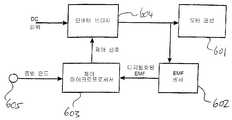
도 2 는 본 발명을 실시한 자유 피스톤 증기 압축기 및 관련 컨트롤러의 블 록 다이어그램,2 is a block diagram of a free piston steam compressor and associated controller in accordance with the present invention;
도 3 은 본 발명의 바람직한 실시예에 따른 스트로크 컨트롤러 프로세스를 도시한 흐름도,3 is a flow diagram illustrating a stroke controller process in accordance with a preferred embodiment of the present invention;
도 4 는 전체 압축기 사이클 동안 시간에 대한 전류 및 전압을 도시한 도면,4 shows current and voltage over time for the entire compressor cycle;
도 5 는 도 3의 프로세스에 의해 사용되는 역치 색인표를 도시한 챠트,5 is a chart showing a threshold index table used by the process of FIG.
도 6 은 설명한 바와 같은 제어를 실행하는 리니어 압축기에 대하여 최소 헤드 클리어런스("갭")와 증발 온도(Tevap)를 도시한 도면.6 shows a minimum head clearance (“gap”) and evaporation temperature (Tevap ) for a linear compressor that performs the control as described.
본 발명은 리니어 전기 모터에 의해서 동력이 제공되는 자유 피스톤 왕복운동 압축기를 제어하기 위한 방법을 제공한다.The present invention provides a method for controlling a free piston reciprocating compressor powered by a linear electric motor.
이하의 설명에서 본 발명은 원통형 리니어 모터와 관련하여 설명되지만, 본원 발명의 방법은 일반적으로 리니어 모터에 동일하게 적용가능하고, 특히 평탄한 리니어 모터에도 또한 동일하게 적용가능하다. 예를 들면, 본 명세서에 참조로 통합된 본 출원인이 출원한 국제특허출원 PCT/NZ00/00201를 참조하라. 당업자는 여기에 설명된 제어 전략을 어떠한 형태의 리니어 모터 구동식 자유 피스톤 압축기에 적용하는데 특별한 노력을 기울이지 않아도 된다.In the following description the invention is described with reference to a cylindrical linear motor, but the method of the invention is generally equally applicable to linear motors, in particular also to flat linear motors. See, for example, International Patent Application PCT / NZ00 / 00201, filed by Applicant, which is hereby incorporated by reference. Those skilled in the art do not need to make any special efforts to apply the control strategy described herein to any type of linear motor driven free piston compressor.
도 1에 도시된 압축기는 왕복운동 자유 피스톤 압축기에 연결된 영구자석 리니어 모터를 포함한다. 실린더(9)는 압축기 셸(30) 내에서 원통형 스프링(14)에 의해 지지된다. 피스톤(11)은 스프링 장착부(25)를 경유하여 스트링(13)과 원통형 보어에 의해 형성된 베어링에 의해서 방사상으로 지지된다. 베어링은 공지된 여러가지 방법중의 하나에 의해서 윤활되는 것이 될 수 있다. 예를 들면, 여기에 참조로 통합된 국제특허출원 PCT/NZ00/00202에 설명된 가스 베어링 또는 국제특허출원 공보 WO00/26536에 설명된 오일 베어링이 될 수 있다. 마찬가지로 본 발명은 교호 왕복운동 시스템에 적용가능하다. 예를 들면, 이하에 압축기는 가스/기계적인 스프링 조합 시스템으로 설명되지만, 본 발명은 전적으로 가스 스프링 시스템과 함께 사용될 수 있다.The compressor shown in FIG. 1 comprises a permanent magnet linear motor connected to a reciprocating free piston compressor. The cylinder 9 is supported by a
실린더(9)내에서 피스톤(11)의 왕복운동은 흡입 튜브(12), 흡입 포트(26), 흡입 머플러(20), 밸브 플레이트(21)의 밸브 포트(24)를 통하여 압축 공간(28)내로 가스를 끌어낸다. 그 후에 압축 가스는 배출 머플러(19)의 배출 밸브 포트(23)를 통하여 나와서 배출 튜브(18)를 통하여 빠져나간다. 유동 경로에 대한 다양한 변경이 가능하다. 예를 들면, 흡입 경로는 피스톤 크라운을 통한 흡입 포트를 갖는 피스톤의 내부를 통과하는 것이 될 수 있다.The reciprocating movement of the
압축기 모터는 두 부분의 고정자(5, 6) 및 아마츄어(22)를 포함한다. 피스톤(11)의 왕복운동을 발생시키는 힘은 아마츄어(22)내의 두개의 반경방향으로 자화되는 환형상 영구자석(3, 4)(플랜지(7)에 의해 피스톤(11)에 부착), 공기 갭(33)에서의 자기장(고정자(6)와 코일(1, 2)에 의해서 유도)의 상호작용으로부터 생긴다.The compressor motor comprises two parts of
도 1에 도시된 두개의 코일을 가지고 있는 압축기 모터는 고정자(6)의 내부를 따라 축선방향으로, 단부 고정자 투스(tooth)(32)를 통하여 반경방향 외부로, 공기 갭(33)을 가로질러 흐르고 그 다음에 후방 철심(5)으로 들어가는 플럭스를 생 성하는 코일(1)에 흐르는 전류를 갖는다. 그 후에 전류는 공기 갭(33)을 가로질러 반경방향 내부 및 고정자(6)의 중앙 투스(34)내로 다시 흐르기 전에 짧은 거리(27)에 대해 축선방향으로 흐른다. 제2 코일(2)은 축선방향으로 짧은 거리(29)에 대해 공기 갭을 가로질러 중앙 투스(34)를 통하여 반경방향으로, 그리고 단부 투스(35)내로 공기 갭(33)을 통하여 바깥쪽으로 유동하는 플럭스를 생성한다. 투스(32)로부터 공기 갭(33)을 가로지르는 플럭스는 자석(3)의 자성이 다른 자석(4)과 반대 극성으로 구비된 반경방향으로 자화된 자석(3, 4)에 축선방향의 힘을 유도한다. 후방 철심(5) 대신에 자석과 대향하는 측면에 다른 세트의 코일을 갖는 것으로 하는 것도 가능하다.The compressor motor having the two coils shown in FIG. 1 crosses the
사인파형이 필수적인 것이 아닌 코일(1, 2)의 진동 전류는 기계적인 시스템의 고유 주파수에 가까운 진동 주파수를 갖는 실질적인 상대 운동을 자석과 고정자에 제공하는 진동력을 자석(3, 4)에 대하여 생성한다. 고유 주파수는 스프링(13, 14)의 강성, 실린더(9)와 고정자(6)의 질량, 압축 공간(28)내에서 가스의 부가적인 가스 스프링 효과에 의해서 결정된다. 자석(3, 4)에 대한 진동력은 고정자 부분에 대한 반작용력을 생성한다. 그러므로, 고정자(6)는 접착제, 압착 고정 또는 클램프 등에 의해 실린더(9)에 견고하게 부착되어야 한다. 후방 철심은 고정자 장착부(17)에 클램핑 또는 접합 된다. 고정자 장착부(17)는 실린더(9)에 견고하게 연결된다.The oscillating current of the
제어 방법Control method
압축기 피스톤-스프링 시스템의 고유 주파수로 구동될 때 자유 피스톤 압축기가 특히 효율적이라는 것은 실험으로 입증되었다. 그러나, 신중하게 구비된 금속 스프링뿐만 아니라 고유한 가스 스프링이 있으며, 그 유효 스프링 상수는 변한다. 앞서 설명된 전기 정류식 영구자석 모터는 참고로 여기에 통합된 국제특허출원공보 WO 00/79671에 개시된 바와 같이 전기 정류식 영구자석 모터에서의 실험으로부터 추론된 것을 포함하는 기술을 사용하여 바람직하게 제어된다.Experiments have shown that free piston compressors are particularly efficient when driven at the natural frequency of the compressor piston-spring system. However, there are inherent gas springs as well as carefully equipped metal springs, and their effective spring constants vary. The electrically commutated permanent magnet motor described above is preferably controlled using a technique including those deduced from experiments in the electrically commutated permanent magnet motor as disclosed in International Patent Application Publication WO 00/79671 incorporated herein by reference. do.
리니어 모터가 WO 00/79671에 설명된 바와 같이 제어될 때, 압축기 입력 파워를 피스톤이 실린더의 단부를 둘러싸는 밸브 플레이트와 충돌하는 피스톤의 행정까지 증가시키는 것이 가능하다. 본 출원인은 국제특허출원공보 WO 03/44365에서 충돌을 검출하기 위한 시스템에 대하여 설명하였다. 충돌이 일어날 때 피스톤 왕복운동 주기는 필터링한 또는 평탄화시킨 값과 비교하여 떨어지는 것을 관찰하였다. 피스톤 주기는 하사점과 상사점 사이의 두개의 절반 주기로 이루어지고, 절반 주기는 대칭적이지 않다. 피스톤이 충돌할 때 두 절반 주기의 시간이 감소하지만, 헤드로부터 멀어지게 이동하는 절반 주기가 헤드를 향하여 이동하는 절반 주기보다 길다. 본 발명의 바람직한 실시예에서 충돌 검출은 절반 주기 시간에서 충돌을 나타내는 임의의 급격한 감소에 대한 절반 주기 시간을 모니터링함으로써 제공되고 이에 반응하여 입력 파워가 감소된다.When the linear motor is controlled as described in WO 00/79671, it is possible to increase the compressor input power to the stroke of the piston where the piston collides with the valve plate surrounding the end of the cylinder. Applicant has described a system for detecting collisions in WO 03/44365. It was observed that the piston reciprocation period dropped when compared with the filtered or flattened value. The piston cycle consists of two half cycles between bottom dead center and top dead center, and the half cycles are not symmetrical. The time of the two half cycles decreases when the piston collides, but the half cycle moving away from the head is longer than the half cycle moving toward the head. In a preferred embodiment of the present invention collision detection is provided by monitoring the half cycle time for any sudden decrease indicative of a collision at half cycle time and in response the input power is reduced.
본 발명에 따라 밸브 플레이트에 대한 피스톤 TDC의 접근을 결정하기 위한 시스템을 안출하였다. 헤드에 대한 TDC 위치가 각각의 팽창 및 압축 스트로크의 상대적인 기간에 영향을 미치는 것을 알았다. 헤드에 더욱 가까운 TDC 위치는 헤 드로부터 더욱 떨어져 있는 TDC 위치와 비교하여 압축 스트로크의 기간을 감소시킨다. 헤드에 더욱 가까운 TDC 위치는 헤드로부터 더욱 떨어져 있는 TDC 위치와 비교하여 팽창 스트로크의 기간을 증가시킨다. 본원의 발명자는 충돌 발생시 현저한 감소를 나타내는 헤드에 가까이 유지되는 TDC 위치를 이용하여 리니어 압축기를 작동하는 스트로크 제어를 위한 기초로서 이러한 특성을 사용할 수 있다는 것을 인식하였다. 이것은 피스톤을 위한 근접 또는 절대 위치 센서를 필요로 하지 않고 유지된다. 이것은 WO 03/44365에 설명된 것과 같은 충돌 검출기와 함께 구비될 수 있으며, 양자는 소프트웨어 및 공유 공통 입력 데이터로 실시될 수 있다. 예를 들면, 충돌의 노이즈를 검출하는 마이크로폰과 같은 다른 충돌 검출 시스템이 또한 포함될 수 있다.According to the present invention a system for determining the access of the piston TDC to the valve plate has been devised. It was found that the TDC position relative to the head affects the relative duration of each expansion and compression stroke. The TDC position closer to the head reduces the duration of the compression stroke compared to the TDC position further away from the head. The TDC position closer to the head increases the duration of the inflation stroke compared to the TDC position further away from the head. The inventors of the present application have recognized that this property can be used as the basis for stroke control of operating a linear compressor using a TDC position held close to the head, which shows a significant reduction in collision occurrence. This is maintained without the need for a proximity or absolute position sensor for the piston. It can be equipped with a collision detector as described in WO 03/44365, both of which can be implemented with software and shared common input data. For example, other collision detection systems may also be included, such as microphones that detect noise in collisions.
바람직한 스트로크 제어는 아래와 같이 압축 스트로크의 기간(tC) 및 팽창 스트로크의 기간(tE)로부터 시간차(△t)를 계산한다.Preferred stroke control calculates the time difference Δt from the period tC of the compression stroke and the period tE of the expansion stroke as follows.
△t = tC - tEΔt = tC -tE
비록 이것은 매 사이클에 대해 계산될 수 있지만, 이것은 예를 들면 단일 스트로크와 바로 인접한 것 사이의 차이가 되거나, 또는 단기간의 평균, 매초 스트로크인 여러 스트로크의 최대, 최소 또는 중앙값이 될 수 있다.Although this can be calculated for every cycle, this can be, for example, the difference between a single stroke and the immediate adjoin, or it can be the maximum, minimum or median of several strokes which are short-term averages, strokes per second.
시간차(△t)는 간격을 두고 계산되고 비휘발성 메모리에 저장된 색인표로부터 읽은 역치와 비교된다. 색인표는 작동 조건을 변경하기 위한 역치를 제공하고, 냉동 시스템에서 특히 압축기 흡입 압력은 본질적으로 증발 압력이며 가장 쉽게 측 정되는 증발 온도와 관련되어 있다.The time difference DELTA t is calculated at intervals and compared with a threshold read from an index table stored in a nonvolatile memory. The index table provides a threshold for changing operating conditions, and especially in refrigeration systems, the compressor suction pressure is essentially the evaporation pressure and is associated with the most easily measured evaporation temperature.
색인표는 소정의 압축기 및 냉동 시스템 설계를 위해 사전에 결정될 수 있고 설계에 따라 사용하기 위해서 모든 컨트롤러에 미리 저장될 수 있다. 대안으로 색인표는 작동 조건의 변화하에서 파워를 서서히 증가시키고 여기에 설명된 바와 같은 충돌 검출 장치를 사용하여 충돌이 검출 및 충돌이 발생할 때까지 파워를 증가시킴으로써 역치를 알아내고, 충돌 직전에 관측된 시간차(△t)에 대한 역치로 편향시키는 것을 포함하는 계산 절차에서 각각의 개별적인 압축기에 대해 생성될 수 있다.The index table may be predetermined for a given compressor and refrigeration system design and stored in advance in all controllers for use according to the design. Alternatively, the index table finds the threshold by slowly increasing the power under changes in operating conditions and increasing the power until a collision is detected and crashed using a collision detection device as described herein, It can be generated for each individual compressor in a calculation procedure that includes deflection to a threshold for time difference [Delta] t.
색인표에 대한 대안으로서 압축기의 정상적인 가동중에 역치를 간헐적으로 유도할 수 있다. 예를 들면 역치 유도 절차는 간헐적으로 반복될 수 있다. 이 절차는 충돌이 검출될 때까지 파워 입력을 급격히 증가시키는 동안 시간차(△t)를 모니터링하고 이어서 충돌이 일어나기 바로 전에 관측된 시간차(△t)를 제어 역치로 채택하는 것을 포함할 수 있다.As an alternative to the index table, the threshold can be derived intermittently during normal operation of the compressor. For example, the threshold derivation procedure may be repeated intermittently. This procedure may include monitoring the time difference [Delta] t while rapidly increasing the power input until a collision is detected, and then adopting the observed time difference [Delta] t as a control threshold just before the collision occurs.
상술한 제어 방안은 본 발명의 바람직한 실시 형태이다. 그러나, 본 발명의 범주에서 벗어나지 않고 다른 실시형태도 가능하다. 충돌없는 최대 클리어런스를 성취하는 수준으로 압축기에 대한 파워 입력을 제어하기 위하여 압축 스트로크 기간 및/또는 팽창 스트로크 기간에서 관측된 변화를 사용할 수 있는 다른 제어 알고리즘이 유도될 수 있다.The above-described control method is a preferred embodiment of the present invention. However, other embodiments are possible without departing from the scope of the invention. Other control algorithms can be derived that can use the observed changes in the compression stroke period and / or the expansion stroke period to control the power input to the compressor to a level that achieves a maximum collision free clearance.
첫번째 부가적인 예는 전체 사이클 기간에 대한 압축 스트로크 기간의 비교를 사용하는 것이 될 수 있다.The first additional example may be to use a comparison of the compression stroke duration to the total cycle duration.
다른 예는 전체 사이클 기간과 팽창 스트로크 기간의 비교일 수 있다.Another example may be a comparison of the total cycle duration and the expansion stroke duration.
각각의 경우에 개별적인 절반 사이클 기간 및 전체 사이클 기간은 하나 이상의 절반 사이클 또는 전체 사이클의 평균일 수 있다. 예를 들면 이전의 여섯 사례의 평균이 적합할 수 있다. 대안으로, 기간의 최대, 최소 또는 중앙값이 같은 시기의 세트(예를 들면 이전의 여섯 사례)에서 확인되고 후속 제어를 위해 사용될 수 있다.In each case the individual half cycle period and the full cycle period may be the average of one or more half cycles or the entire cycle. For example, the average of the previous six cases may be appropriate. Alternatively, the maximum, minimum or median of the period can be identified in the same set of periods (eg the previous six cases) and used for subsequent control.
비교 관측 사이의 계산된 관계는 상당한 변화를 받을 수 있다. 예를 들면 계산되는 시간차보다는 오히려 팽창 스트로크 기간에 대한 압축 스트로크 기간의 비율 또는 전체 사이클 기간에 대한 팽창 스트로크 기간의 비율과 같은 비율이 계산된다. 또한 실질적으로 바뀌지 않는 냉동 시스템 조건하에서 압축 스트로크 기간 및/또는 팽창 스트로크의 기간에서의 변화에 민감한 필요 기준을 충족하는 다른 함수가 제안될 수 있다.The calculated relationship between comparative observations can vary significantly. For example, rather than a time difference calculated, a ratio is calculated, such as the ratio of the compression stroke period to the expansion stroke period or the ratio of the expansion stroke period to the entire cycle period. Other functions may also be proposed that meet the necessary criteria sensitive to changes in the duration of the compression stroke and / or the duration of the expansion stroke under refrigeration system conditions that are substantially unchanged.
압축 스트로크 기간과 팽창 스트로크 기간 사이의 관계를 효과적으로 제공하는 가능한 제어 알고리즘이 앞에서 간략히 설명되었다. 이것은 냉동 시스템 조건으로부터 자유로운 적절한 독립성을 제공하는 것으로 밝혀졌다. 효과적인 제어는 본 발명의 발명자에 의해서 색인표의 색인처럼 오직 흡입 압력의 검출을 사용하는 실제적인 작동 조건하에서 달성되었다. 또한 효과적인 제어는 색인표의 값과 각각의 스트로크의 비교, 또는 일정한 값을 갖는 압축 또는 팽창 스트로크의 함수의 비교와 같은 유사한 관계와 함께 팽창 스트로크 및 압축 스트로크 중의 하나만을 모니터링하는 것을 이용하여 달성될 수 있다는 것이 기대된다.A possible control algorithm that effectively provides a relationship between the compression stroke period and the expansion stroke period has been briefly described above. This has been found to provide adequate independence free from refrigeration system conditions. Effective control has been achieved by the inventor of the present invention under practical operating conditions using only the detection of suction pressure, such as the index in the index table. Effective control can also be achieved using monitoring only one of the inflation stroke and the compression stroke with a similar relationship such as the comparison of the values of the index with the respective stroke, or the comparison of the function of the compression or inflation stroke with constant values. It is expected.
이것은 압축 스트로크 기간에서 나타나는 감소보다 팽창 스트로크 기간이 훨씬 큰 증가를 나타낸다는 점에서 특히 효과적이다.This is particularly effective in that the expansion stroke period exhibits a much larger increase than the reduction seen in the compression stroke period.
도 2에 블록 다이어그램의 형태로 도시된 바람직한 컨트롤러에서, 전체 사이클 주기 및 각각의 스트로크의 주기를 검출하기 위하여 백 EMF 검출이 사용된다. EMF 센서(602)는 모터 권선(601)과 병렬로 연결된다. EMF 센서(602)는 모터 권선을 가로지르는 EMF를 표시하는 디지털 출력을 제공한다. EMF 센서(602)의 디지털화된 EMF 출력은 제어 마이크로프로세서(603)에 입력으로 제공된다. 냉매 증발기에 고정된 온도 센서는 증발 온도를 나타내는 출력 신호를 제공한다. 이 신호는 디지털화되어 또 다른 입력으로서 제어 마이크로프로세서(603)에 제공된다. 제어 마이크로프로세서(603)는 디지털화된 EMF 및 증발 온도 입력에 기초하여 제어 신호를 만들고 인버터 브리지(604)에 제어 신호를 제공한다. 인버터 브리지는 제어 마이크로프로세서(603)로부터의 제어 신호에 기초하여 모터 권선(601)에 대한 파워를 개폐한다. 제어 마이크로프로세서(603)를 위한 제어 프로그램은 본 출원인의 국제특허출원공보 WO 00/79671에 개시되어 있다.In the preferred controller shown in the form of a block diagram in FIG. 2, back EMF detection is used to detect the entire cycle period and the period of each stroke. The
본 발명의 바람직한 실시예 및 WO 03/044365에 설명된 충돌 검출을 실시하기 위하여, 제어 마이크로프로세서는 스트로크 주기 결정 알고리즘을 실시한다. 스트로크 주기 결정 알고리즘은 EMF 센서(602)로부터 수신된 디지털화된 EMF 신호를 모니터링함으로써 각각의 압축 및 팽창 스트로크의 기간을 결정한다. 이 알고리즘은 백 EMF 영 교차 사이의 시간 주기로 스트로크 주기를 결정한다. 도 4는 WO 00/79671에 개시된 제어 방법에 따라 작동되는 리니어 모터에서의 파형을 예시하고 있다. 하나의 파형은 모터 권선 전압(400)을 나타낸다. 다른 파형은 모터 전류(402)를 나타낸다. 이 도면은 팽창 스트로크 및 압축 스트로크 양자를 포함하는 단일의 전체 주기에 대한 파형을 도시한다. 이 주기에서 모터는 제어된 시간(ton) 동안 각각의 절반 사이클에서 전류가 통하게 된다. 고정자 권선 전압은 팽창 스트로크의 시작(420)에서 켜진다. 모터 전류(402)는 전압이 가해지는 동안 형성된다. 이 고정자 권선 전압은 시간(ton(ex))에서 제거된다. 전압이 제거되면 전류(402)는 시간(ton(ex))과 시간(toff1(ex)) 사이에서 영으로 감소한다. 이러한 감소 동안에 감소하는 전류는 고정자 권선 전압을 완전히 네거티브로 되게 한다. 팽창 스트로크의 잔여 기간 동안 모터 권선 EMF 는 아마추어의 운동에 의해 유도된 백 EMF(404) 이다. 아마추어가 팽창 스트로크의 끝에서 헤드로부터 가장 먼 위치(하사점 또는 BDC 라고 한다)에 도달할 때 EMF(404)는 영으로 감소한다. 영 교차(toff2(ex))는 팽창 스트로크의 끝 및 압축 스트로크의 시작 순간을 나타낸다. 압축 스트로크의 시작에서 구동 전압(422)이 모터 권선에 인가되고 전류는 전류 곡선(424)에 의해 표시된 것과 같이 상승하기 시작한다. 시간(ton(comp))이 경과한 후(도 6의 지점(ton(comp)) 구동 전압은 제거된다. 구동 전압이 제거되면 전류는 도면부호(427)로 표시된 바와 같이 떨어지고 고정자 권선 전압은 도면부호(425)로 표시된 바와 같이 완전히 포지티브로 된다. 일단 전류가 시간(ton(comp))에서 영으로 감소되면 EMF(406)는 권선에서 유도된 백 EMF를 나타낸다. 아마추어 속도가 헤드에 가장 근 접한 위치(상사점 또는 TDC 라고 한다)에 도달하여 감소될 때, 유도된 백 EMF(406)는 영으로 떨어진다. 전환하기 전에 상사점(TDC)에서 아마추어 속도는 순간적으로 영이 되고 시간(toff2(comp))에서 백 EMF 영 교차가 발생한다.In order to implement the collision detection described in the preferred embodiment of the present invention and in WO 03/044365, the control microprocessor implements a stroke period determination algorithm. The stroke period determination algorithm determines the duration of each compression and expansion stroke by monitoring the digitized EMF signal received from the
제어 마이크로프로세서(603)에서 실행되는 스트로크 주기 결정 알고리즘은 영 교차 시점((toff2(comp)) 및 (toff2(comp)))을 식별하도록 프로그램된다. 팽창과 수축 사이를 식별하지 않는 영 교차 시점 사이의 시간 기간은 압축 스트로크 기간과 팽창 스트로크 기간 사이에 번갈아 일어나는 스트로크 기간에 대한 각각의 단일 스트로크 기간을 나타낸다. 스트로크 주기 결정 알고리즘은 두 개의 출력을 갖는다. 하나는 영 교차의 발생을 나타낸다. 다른 하나는 가장 최근의 스트로크 기간을 나타낸다.The stroke period determination algorithm executed in the
제어 마이크로프로세서(603)는 전류 공급 시간(ton)을 연속적으로 조절하기 위한 알고리즘을 실행한다. 이 프로세스는 도 3에 도시되어 있다. 이 프로세스는 입력으로서 스트로크 결정기의 출력, 증발기 온도 센서 및 압축기 수요(Pcommand) 표시기의 출력을 취한다. 압축기 수요(Pcommand)는 냉동기 작동 조건에 기초하여 마이크로프로세서 또는 전체 냉동기 컨트롤러에 의해 결정된다. 본질적으로 이것은 압축기에 의해서 전달되도록 요구되는 용량과 관련되어 있다. 도시된 예에서 압축기 수요(Pcommand)는 네 개의 값 중의 하나를 취할 수 있다. "0" 값은 압축기의 즉각적인 정지를 나타낸다. "1" 값은 용량의 점진적인 감소를 나타낸다. "2" 값은 용량 을 현재 수준으로 유지하는 것을 나타내고 "3" 값은 용량을 점진적으로 증가시키는 것을 나타낸다. 용량을 변경하는 것은 각각의 절반 사이클에서 전류 공급의 기간의 상응하는 증가 또는 감소에 의해서 달성된다. 이러한 제어의 목적을 위해서 시간(ton)은 가변적이며 그 값은 전류 공급의 기간(밀리초(ms))이다.The
도 3을 참조하면, 바람직한 방법은 단계(302)에서 시작하여 연속적으로 반복되는 루프를 포함한다. 각각의 루프의 시작에서 이 방법은 스트로크 결정 알고리즘(306)에 의해 표시할 영 교차를 위해 단계(304)에서 대기한다. 영 교차가 ton 제어 루프의 연속적인 실행으로 인도하는 인터럽트로서 작용하므로, 이 루프는 절반 사이클마다 한번 실행한다. 스트로크 결정기(306)에 의해 영 교차가 표시될 때 이 방법은 단계(308)로 진행하여 증발 온도 센서(310)로부터 증발 온도를 획득한다. 그 다음에 단계(312)로 진행하여 △t에 대한 역치(△tthreshold)가 색인표(314)로부터 읽어 들여진다. 색인표(314)는 증발 온도의 함수로서 △t 역치를 기록한다. "△t 역치 대비 증발 온도" 색인표의 예를 도시하는 플로트가 도 5로 제공된다.Referring to FIG. 3, the preferred method includes a loop that begins in
단계(316)에서 스트로크 결정기(306)로부터 마지막 스트로크 주기가 획득되어 변수(tn)로 지정된다. 단계(318)로 진행하여, △t는 가장 최근의 스트로크 주기(tn)와 그 바로 앞의 스트로크 주기(tn-1) 사이의 차이의 절대값으로 계산된다. 프로그램은 단계(318)에서 계산된 △t가 단계(312)의 색인표(314)에서 읽어 들인 역치(△tthreshold)와 비교되는 결정 단계(320)로 진행한다.In
만약 △t가 역치(△tthreshold)보다 크면 알고리즘은 단계(322)로 진행한다. 만약 △t가 역치(△tthreshold)보다 크면, 이것은 압축기가 최대 용량에 근접하여 작동하는 것을 나타낸다. 따라서 단계(322)에서 변수(Pincrese)는 "0"으로 설정된다. 그 다음에 알고리즘은 단계(324)로 진행한다.If Δt is greater than the Δtthreshold , the algorithm proceeds to step 322. If Δt is greater than the Δtthreshold , this indicates that the compressor is operating near its maximum capacity. Thus, in
만약 단계(320)에서 △t가 역치(△tthreshold)보다 크지 않으면 알고리즘은 단계(326)로 진행한다. 만약 △t가 역치(△tthreshold)보다 작거나 또는 같으면, 이것은 압축기가 아직 최소 헤드 클리어런스로 작동하지 않으며 그 이상의 용량이 사용가능하다는 것을 나타낸다. 따라서 변수(Pincrese)는 "1"로 설정된다. 그 다음에 알고리즘은 단계(324)로 진행한다.If Δt in
단계(324)에서 변수(tn-1)는 tn의 값으로 설정된다. 이것은 다음 루프의 반복에서 사용하기 위한 것이다.In
그 다음에 알고리즘은 듀티 시간(ton)이 조절되는 단계(326)로 진행한다. ton에 대한 조절은 두 변수(Pcommand 및 Pincrese)에 기초한 색인표에서 찾는다. 앞서 설명된 바와 같이 Pcommand입력은 요청된 압축기 작동 변화를 나타낸다. 알고리즘에서 먼저 설정된 Pincrese는 압축기가 이미 추가적인 용량의 여유가 없는 용량으로 작동되는 여부를 나타낸다. 따라서 Pincrese가 1인 경우 추가적으로 사용할 수 있는 용 량이 있으며 ton 조절은 Pcommand에 의해 요청된 조절과 대응한다. 작은 용량의 높은 작동 주파수 압축기의 경우에, 도시된 바와 같이 10㎲ 또는 0.1㎲ 만큼 줄여 ton 조절하다. Pincrese가 0인 경우, 이것은 추가적인 용량이 사용가능하지 않으며 피스톤이 충돌에 근접한 위치로 이동될 수 있는 것을 나타낸다. 따라서 ton에 대한 조절은 Pcommand와 무관하고 모든 경우에 예를 들면 10㎲씩 ton 기간을 감소시킨다.The algorithm then proceeds to step 326 where the duty time ton is adjusted. The adjustment for ton is found in the index table based on two variables (Pcommand and Pincrese ). Pcommand as described above The input represents the requested compressor operation change. Pincrese set first in the algorithm Indicates whether the compressor is already operating at capacity with no additional capacity. Thus Pincrese If 1, additional capacity is available and ton adjustment is Pcommand. Corresponds to the adjustment requested by. In the case of small capacity high operating frequency compressors, ton control is reduced by 10 Hz or 0.1 Hz as shown. Pincrese If 0, this indicates that no additional capacity is available and the piston can be moved to a position close to the impact. So the adjustment for ton is Pcommand In all cases, the ton period is reduced by, for example, 10 ms.
단계(326)에서 ton 조절을 하면 알고리즘은 단계(327)에서 복귀하여 시작 단계(302)로 진행하여 루프를 다시 반복한다.With ton adjustment in
작동시에 전체 컨트롤러가 압축기로부터 최대 용량을 요구하는 경우(제품이 냉동 컴파트먼트에 추가되는 경우), Pcommand는 3으로 항상 설정될 것이다. 이것은 증발 온도 센서(310)에 의해 검출된 증발 온도에 대해 △t가 역치(△tthreshold)보다 클 때까지 ton 을 형성(각각의 절반 주기의 0.1㎲ 씩)하게 한다. 일단 △t가 역치(△tthreshold)보다 커지면, △t가 역치(△tthreshold)보다 크지 않을 때까지 ton 은 아래쪽으로 조절된다(각각의 절반 주기의 10㎲ 씩). 그 후의 반복에서 △t가 역치(△tthreshold)보다 커질 때까지 ton 은 위쪽으로 조절된다. 이러한 피드백 제어는 온도 변화가 발생할 때 센서(310)에 의해 검출된 증발 온도의 변화에 응답하여 △t가 역치에 대략 동일하게 되는 수준 부근에서 ton 변동을 보인다.In operation, if the entire controller requires the maximum capacity from the compressor (if the product is added to the refrigeration compartment), the Pcommand will always be set to 3. This causes ton to be formed (by 0.1 Hz of each half cycle) until Δt is greater than thethreshold Δt threshold for the evaporation temperature detected by
발명자는 여기에 설명된 알고리즘을 본 출원인이 출원하여 계류중인 뉴질랜드 특허출원 526361에 개시된 것과 같은 리니어 압축기에 대해서 시험하였다. 이 압축기에는 상사점 위치에서 헤드에 대한 피스톤의 접근을 측정하기 위하여 근접 센서가 설치되었다. 근접 센서 출력은 근접 센서 출력은 최대 용량(Pcommand= 3)이 요구되는 동안 소정의 증발 온도에서 정상 상태로 작동하는 주기에 걸쳐 측정된 최근접 상사점 위치를 결정하기 위하여 분석되고 모니터링 되었다. 여덟 개의 증발 온도에 대한 헤드 클리어런스 결과가 도 5에 도시되었다. 이것은 본 발명의 제어가 충돌없이 대략 0.2㎜ 내지 0.25㎜의 일관된 최소 클리어런스 갭을 달성한 것을 나타낸다. 클리어런스 갭은 도 5의 챠트에 따라 역치를 사용하여 얻었다. 도 5의 챠트의 역치는 0.2㎜의 의도된 클리어런스 갭을 위하여 선택되었다.The inventors tested the algorithm described herein for a linear compressor such as that disclosed in Applicant's pending New Zealand patent application 526361. The compressor is equipped with a proximity sensor to measure the piston's approach to the head in the top dead center position. Proximity sensor output is the maximum capacity of the proximity sensor output (Pcommand = 3) was analyzed and monitored to determine the nearest top dead center position measured over the period of steady state operation at the desired evaporation temperature. Head clearance results for eight evaporation temperatures are shown in FIG. 5. This indicates that the control of the present invention achieved a consistent minimum clearance gap of approximately 0.2 mm to 0.25 mm without collision. Clearance gaps were obtained using thresholds according to the chart of FIG. 5. The threshold of the chart of FIG. 5 was chosen for the intended clearance gap of 0.2 mm.
앞에서 언급된 바와 같이, 충돌 검출기는 또한 마이크로프로세서(603)에 저장된 소프트웨어로 실행될 수 있다. 충돌 검출기는 전기적인 주기 데이터를 수신하고 피스톤이 실린더 헤드와 충돌할 때 전체 사이클에서의 급격한 감소를 검출한다. 충돌 검출기는 도 3의 제어 알고리즘과 무관하게 ton 값을 수정하거나 또는 제어 알고리즘에 통합될 수 있다.As mentioned above, the collision detector may also be implemented in software stored in the
본 발명의 바람직한 실시예에서 제어 알고리즘 및 스트로크 결정기는 외부 로직에서 부분적으로 또는 전체적으로 실현되거나, 하나 이상의 모듈에 배당되거나, 또는 개별적인 아날로그 회로에서 동일하게 실현될 수 있는 제어 마이크로프로세서(603)에 의해서 실행되는 소프트웨어로 실현되는 것으로 설명되었다. 설명되 었던 것은 본 발명의 바람직한 실시형태이다. 본 발명의 기술사상에서 벗어나지 않고 본 발명의 다른 실시형태가 가능하다는 것은 당업자에게 자명한 것이며, 이것은 넓은 의미에서 본 발명의 범주에 속하는 것이다.In a preferred embodiment of the present invention, the control algorithm and the stroke determiner are executed by a
Claims (21)
Translated fromKoreanApplications Claiming Priority (2)
| Application Number | Priority Date | Filing Date | Title |
|---|---|---|---|
| NZ527999 | 2003-09-02 | ||
| NZ527999ANZ527999A (en) | 2003-09-02 | 2003-09-02 | Controller improvements |
Publications (1)
| Publication Number | Publication Date |
|---|---|
| KR20060119924Atrue KR20060119924A (en) | 2006-11-24 |
Family
ID=34270856
Family Applications (1)
| Application Number | Title | Priority Date | Filing Date |
|---|---|---|---|
| KR1020067004322AWithdrawnKR20060119924A (en) | 2003-09-02 | 2004-09-02 | Linear motor controller |
Country Status (12)
| Country | Link |
|---|---|
| US (1) | US8231355B2 (en) |
| EP (1) | EP1664533B1 (en) |
| JP (1) | JP4604035B2 (en) |
| KR (1) | KR20060119924A (en) |
| CN (1) | CN1846061B (en) |
| AT (1) | ATE458912T1 (en) |
| AU (1) | AU2004269283B2 (en) |
| BR (1) | BRPI0413910A (en) |
| DE (1) | DE602004025716D1 (en) |
| MX (1) | MXPA06002106A (en) |
| NZ (1) | NZ527999A (en) |
| WO (1) | WO2005021966A1 (en) |
Families Citing this family (18)
| Publication number | Priority date | Publication date | Assignee | Title |
|---|---|---|---|---|
| KR100524475B1 (en)* | 2004-01-09 | 2005-10-31 | 삼성전자주식회사 | linear compressor and control method thereof |
| WO2005072074A2 (en)* | 2004-01-28 | 2005-08-11 | Leiv Eiriksson Nyskaping As | Working machine with an electromechanical converter |
| AU2006201260B2 (en) | 2005-04-19 | 2011-09-15 | Fisher & Paykel Appliances Limited | Linear Compressor Controller |
| US7690199B2 (en) | 2006-01-24 | 2010-04-06 | Altor Limited Lc | System and method for electrically-coupled thermal cycle |
| US8079825B2 (en)* | 2006-02-21 | 2011-12-20 | International Rectifier Corporation | Sensor-less control method for linear compressors |
| BRPI0705049B1 (en)* | 2007-12-28 | 2019-02-26 | Embraco Indústria De Compressores E Soluções Em Refrigeração Ltda | GAS COMPRESSOR MOVED BY A LINEAR MOTOR, HAVING AN IMPACT DETECTOR BETWEEN A CYLINDER AND PISTON, DETECTION METHOD AND CONTROL SYSTEM |
| JP5553296B2 (en)* | 2009-03-09 | 2014-07-16 | Icファン V−Tech株式会社 | Electronics |
| WO2011091022A1 (en)* | 2010-01-19 | 2011-07-28 | Altor Limited Lc | System and method for electrically-coupled heat engine and thermal cycle |
| BRPI1101436A2 (en)* | 2011-04-04 | 2013-06-11 | Whirlpool Sa | high frequency permanent motor linear reciprocating compressor operating at high frequency |
| JP2014057385A (en)* | 2012-09-11 | 2014-03-27 | Toyota Motor Corp | Controller of dynamo-electric machine and dynamo-electric machine drive system including the same |
| DE102013017944A1 (en)* | 2013-10-29 | 2015-04-30 | Linde Aktiengesellschaft | Method for knock control in a reciprocating compressor |
| US9577562B2 (en)* | 2014-12-05 | 2017-02-21 | Raytheon Company | Method and apparatus for back electromotive force (EMF) position sensing in a cryocooler or other system having electromagnetic actuators |
| BR102015021009B1 (en)* | 2015-08-31 | 2022-05-03 | Embraco Indústria De Compressores E Soluções Em Refrigeração Ltda | Method and system of protection and diagnosis of a linear compressor and linear compressor |
| US10422329B2 (en) | 2017-08-14 | 2019-09-24 | Raytheon Company | Push-pull compressor having ultra-high efficiency for cryocoolers or other systems |
| US11255318B2 (en)* | 2017-11-10 | 2022-02-22 | Motor Components, Llc | Electric control module solenoid pump |
| CN110410304B (en)* | 2018-04-28 | 2022-03-29 | 青岛海尔智能技术研发有限公司 | Sine wave control method for linear compressor |
| DE102018212985A1 (en)* | 2018-08-03 | 2020-02-06 | Robert Bosch Gmbh | Pump and method for operating it and for determining an upper and / or lower dead center |
| CN112746948B (en)* | 2019-10-31 | 2022-07-26 | 青岛海尔智能技术研发有限公司 | Method and device for controlling a DC linear compressor, DC linear compressor |
Family Cites Families (60)
| Publication number | Priority date | Publication date | Assignee | Title |
|---|---|---|---|---|
| US3886419A (en)* | 1973-04-14 | 1975-05-27 | Sawafuji Electric Co Ltd | Electrical refrigerating compressor |
| US4036018A (en)* | 1976-02-27 | 1977-07-19 | Beale William T | Self-starting, free piston Stirling engine |
| US4179899A (en)* | 1977-06-24 | 1979-12-25 | Sawafuji Electric Co. Ltd. | Refrigerating system |
| IL54107A (en)* | 1978-02-22 | 1981-06-29 | Yeda Res & Dev | Electromagnetic linear motion devices |
| JPS5520335A (en)* | 1978-07-28 | 1980-02-13 | Sawafuji Electric Co Ltd | Cooler |
| SU792511A1 (en) | 1978-09-28 | 1980-12-30 | За витель | Linear electric motor |
| JPS56574A (en)* | 1979-06-13 | 1981-01-07 | Sawafuji Electric Co Ltd | Oscillation type compressor |
| JPS56129780A (en)* | 1980-03-13 | 1981-10-12 | Sawafuji Electric Co Ltd | Oscillatory type compressor |
| US4349757A (en)* | 1980-05-08 | 1982-09-14 | Mechanical Technology Incorporated | Linear oscillating electric machine with permanent magnet excitation |
| US4291258A (en)* | 1980-06-17 | 1981-09-22 | Mechanical Technology Incorporated | DC Excitation control for linear oscillating motors |
| US4602174A (en)* | 1983-12-01 | 1986-07-22 | Sunpower, Inc. | Electromechanical transducer particularly suitable for a linear alternator driven by a free-piston stirling engine |
| NZ213490A (en)* | 1985-09-16 | 1990-03-27 | Fisher & Paykel | Cyclic motor reversal by forced commutation |
| US5045748A (en)* | 1985-11-15 | 1991-09-03 | General Electric Company | Tungsten-halogen incandescent and metal vapor discharge lamps and processes of making such |
| JPS62178832A (en)* | 1986-02-03 | 1987-08-05 | Hitachi Ltd | Control circuit for air conditioner with inverter |
| US4713939A (en) | 1986-05-23 | 1987-12-22 | Texas Instruments Incorporated | Linear drive motor with symmetric magnetic fields for a cooling system |
| US4836757A (en)* | 1987-02-13 | 1989-06-06 | Mechanical Technology Incorporated | Pressure actuated movable head for a resonant reciprocating compressor balance chamber |
| JPS63193778U (en)* | 1987-06-03 | 1988-12-13 | ||
| JPH059508Y2 (en) | 1987-06-17 | 1993-03-09 | ||
| JPH01149575U (en) | 1988-04-06 | 1989-10-17 | ||
| EP0374805B1 (en) | 1988-12-18 | 1994-11-02 | Buck Werke GmbH & Co | Electronically commutated synchronous driving motor |
| US5092748A (en)* | 1990-09-06 | 1992-03-03 | Ketema Aerospace & Electronics Division | Fuel metering pump system |
| US5017854A (en) | 1990-10-29 | 1991-05-21 | Hughes Aircraft Company | Variable duty cycle pulse width modulated motor control system |
| JP3249226B2 (en) | 1993-02-05 | 2002-01-21 | 三菱重工業株式会社 | Fuel gas supply system for torch ignition type gas engine |
| US5342176A (en)* | 1993-04-05 | 1994-08-30 | Sunpower, Inc. | Method and apparatus for measuring piston position in a free piston compressor |
| EP0652632B1 (en) | 1993-10-08 | 2002-02-27 | Sawafuji Electric Co., Ltd. | Power supply for vibrating compressors |
| US5525845A (en)* | 1994-03-21 | 1996-06-11 | Sunpower, Inc. | Fluid bearing with compliant linkage for centering reciprocating bodies |
| WO1995033419A1 (en)* | 1994-06-06 | 1995-12-14 | Teledyne Water Pik Division Of Teledyne Industries, Inc. | High frequency electric toothbrush |
| US5592257A (en)* | 1994-08-24 | 1997-01-07 | Nikon Corporation | Electronic flash device with slave emission function |
| JPH08210247A (en)* | 1995-02-07 | 1996-08-20 | Sawafuji Electric Co Ltd | Vibration compressor power supply |
| US5592057A (en)* | 1995-06-23 | 1997-01-07 | Applied Motion Products, Inc. | Step motor and servo motor indexer |
| JPH0960580A (en)* | 1995-08-28 | 1997-03-04 | Sawafuji Electric Co Ltd | Driving method of vibration type compressor |
| US5907201A (en)* | 1996-02-09 | 1999-05-25 | Medis El Ltd. | Displacer assembly for Stirling cycle system |
| JP3814328B2 (en) | 1996-03-14 | 2006-08-30 | 松下冷機株式会社 | Vibration type compressor |
| US5980211A (en)* | 1996-04-22 | 1999-11-09 | Sanyo Electric Co., Ltd. | Circuit arrangement for driving a reciprocating piston in a cylinder of a linear compressor for generating compressed gas with a linear motor |
| EP0972332B1 (en) | 1997-02-05 | 2004-04-28 | Fisher & Paykel Appliances Limited | Brushless dc motor control |
| JP3674216B2 (en)* | 1997-02-25 | 2005-07-20 | 松下電工株式会社 | Drive control method for linear vibration motor |
| US6203292B1 (en) | 1997-04-20 | 2001-03-20 | Matsushita Refrigeration Company | Oscillation-type compressor |
| US5945748A (en)* | 1997-04-29 | 1999-08-31 | Lg Electronics, Inc. | Linear motor structure for linear compressor |
| TW353707B (en)* | 1997-09-26 | 1999-03-01 | Nat Science Council | Control device for linear compressor |
| US6077054A (en)* | 1997-12-23 | 2000-06-20 | Samsung Electronics Co., Ltd. | Stator of linear compressor |
| US6084320A (en) | 1998-04-20 | 2000-07-04 | Matsushita Refrigeration Company | Structure of linear compressor |
| CA2344356A1 (en)* | 1998-09-16 | 2000-03-23 | Airxcel, Inc. | Frequency control of linear motors |
| DE19952578B4 (en)* | 1998-11-04 | 2005-11-24 | Lg Electronics Inc. | Apparatus and method for controlling a linear compressor |
| KR100308279B1 (en) | 1998-11-04 | 2001-11-30 | 구자홍 | Linear compressor |
| US6203288B1 (en)* | 1999-01-05 | 2001-03-20 | Air Products And Chemicals, Inc. | Reciprocating pumps with linear motor driver |
| JP3962254B2 (en) | 1999-06-21 | 2007-08-22 | フィッシャー アンド ペイケル アプライアンシーズ リミテッド | Linear motor |
| GB2354557B (en) | 1999-09-16 | 2003-03-05 | Ernest James Bransden | Reciprocating electromagnetic pump |
| NZ500681A (en) | 1999-10-21 | 2002-06-28 | Fisher & Paykel Appliances Ltd | A linear compressor with gas bearing passages between cylinder and cylinder lining |
| JP2001128434A (en)* | 1999-10-27 | 2001-05-11 | Matsushita Refrig Co Ltd | Linear motor |
| FR2801645B1 (en)* | 1999-11-30 | 2005-09-23 | Matsushita Electric Industrial Co Ltd | DEVICE FOR DRIVING A LINEAR COMPRESSOR, SUPPORT AND INFORMATION ASSEMBLY |
| BR9907432B1 (en)* | 1999-12-23 | 2014-04-22 | Brasil Compressores Sa | COMPRESSOR CONTROL METHOD, PISTON POSITION MONITORING SYSTEM AND COMPRESSOR |
| DE10019419A1 (en) | 2000-04-19 | 2001-10-25 | Bosch Gmbh Robert | Cooling system for motor vehicle detects faulty positioning of cooling flow closure unit from variation with time of temperature difference between model and actual temperature variation |
| TW504546B (en) | 2000-10-17 | 2002-10-01 | Fisher & Amp Paykel Ltd | A linear compressor |
| US6536326B2 (en)* | 2001-06-15 | 2003-03-25 | Sunpower, Inc. | Control system and method for preventing destructive collisions in free piston machines |
| US6718781B2 (en)* | 2001-07-11 | 2004-04-13 | Thermo King Corporation | Refrigeration unit apparatus and method |
| US6685438B2 (en)* | 2001-08-01 | 2004-02-03 | Lg Electronics Inc. | Apparatus and method for controlling operation of reciprocating compressor |
| JP2003065244A (en)* | 2001-08-30 | 2003-03-05 | Matsushita Electric Ind Co Ltd | Control drive device and control drive method for linear compressor |
| NZ515578A (en)* | 2001-11-20 | 2004-03-26 | Fisher & Paykel Appliances Ltd | Reduction of power to free piston linear motor to reduce piston overshoot |
| JP3854556B2 (en) | 2002-09-11 | 2006-12-06 | 三菱重工業株式会社 | Gas turbine plant control mechanism |
| NZ526361A (en) | 2003-05-30 | 2006-02-24 | Fisher & Paykel Appliances Ltd | Compressor improvements |
- 2003
- 2003-09-02NZNZ527999Apatent/NZ527999A/ennot_activeIP Right Cessation
- 2004
- 2004-09-02AUAU2004269283Apatent/AU2004269283B2/ennot_activeCeased
- 2004-09-02EPEP04775133Apatent/EP1664533B1/ennot_activeExpired - Lifetime
- 2004-09-02CNCN2004800250586Apatent/CN1846061B/ennot_activeExpired - Fee Related
- 2004-09-02JPJP2006525295Apatent/JP4604035B2/ennot_activeExpired - Fee Related
- 2004-09-02KRKR1020067004322Apatent/KR20060119924A/ennot_activeWithdrawn
- 2004-09-02BRBRPI0413910-0Apatent/BRPI0413910A/ennot_activeApplication Discontinuation
- 2004-09-02MXMXPA06002106Apatent/MXPA06002106A/ennot_activeApplication Discontinuation
- 2004-09-02DEDE602004025716Tpatent/DE602004025716D1/ennot_activeExpired - Lifetime
- 2004-09-02WOPCT/NZ2004/000208patent/WO2005021966A1/enactiveApplication Filing
- 2004-09-02USUS10/569,747patent/US8231355B2/ennot_activeExpired - Fee Related
- 2004-09-02ATAT04775133Tpatent/ATE458912T1/ennot_activeIP Right Cessation
Also Published As
| Publication number | Publication date |
|---|---|
| AU2004269283A1 (en) | 2005-03-10 |
| US8231355B2 (en) | 2012-07-31 |
| EP1664533A1 (en) | 2006-06-07 |
| MXPA06002106A (en) | 2006-05-31 |
| CN1846061B (en) | 2010-04-21 |
| DE602004025716D1 (en) | 2010-04-08 |
| EP1664533A4 (en) | 2008-12-03 |
| CN1846061A (en) | 2006-10-11 |
| BRPI0413910A (en) | 2006-10-24 |
| EP1664533B1 (en) | 2010-02-24 |
| JP4604035B2 (en) | 2010-12-22 |
| JP2007504394A (en) | 2007-03-01 |
| NZ527999A (en) | 2005-08-26 |
| AU2004269283B2 (en) | 2008-06-05 |
| WO2005021966A1 (en) | 2005-03-10 |
| US20070152512A1 (en) | 2007-07-05 |
| ATE458912T1 (en) | 2010-03-15 |
Similar Documents
| Publication | Publication Date | Title |
|---|---|---|
| KR20060119924A (en) | Linear motor controller | |
| KR100776360B1 (en) | A method of controlling a linear compressor, a free piston gas compressor using the method, and a refrigerator incorporating such compressor | |
| KR100587795B1 (en) | Linear motor controller | |
| CN100529393C (en) | Free piston type linear compressor engine and engine strong control method | |
| JP5406218B2 (en) | Linear compressor control system and method | |
| KR100543950B1 (en) | Linear motor | |
| CN100557240C (en) | Linear compressor controller | |
| EP1715184B1 (en) | Linear compressor controller | |
| NZ539554A (en) | Free piston linear compressor controller | |
| MXPA06004217A (en) | Linear compressor controller | |
| HK1064146B (en) | Linear motor controller |
Legal Events
| Date | Code | Title | Description |
|---|---|---|---|
| PA0105 | International application | Patent event date:20060302 Patent event code:PA01051R01D Comment text:International Patent Application | |
| PG1501 | Laying open of application | ||
| PC1203 | Withdrawal of no request for examination | ||
| WITN | Application deemed withdrawn, e.g. because no request for examination was filed or no examination fee was paid |