KR20060114354A - Optical connector, optical fiber with connector, optical fiber connection device, and optical fiber connection method - Google Patents
Optical connector, optical fiber with connector, optical fiber connection device, and optical fiber connection methodDownload PDFInfo
- Publication number
- KR20060114354A KR20060114354AKR1020067012580AKR20067012580AKR20060114354AKR 20060114354 AKR20060114354 AKR 20060114354AKR 1020067012580 AKR1020067012580 AKR 1020067012580AKR 20067012580 AKR20067012580 AKR 20067012580AKR 20060114354 AKR20060114354 AKR 20060114354A
- Authority
- KR
- South Korea
- Prior art keywords
- ferrule
- optical fiber
- optical
- fiber
- connector
- Prior art date
- Legal status (The legal status is an assumption and is not a legal conclusion. Google has not performed a legal analysis and makes no representation as to the accuracy of the status listed.)
- Granted
Links
Images


Classifications
- G—PHYSICS
- G02—OPTICS
- G02B—OPTICAL ELEMENTS, SYSTEMS OR APPARATUS
- G02B6/00—Light guides; Structural details of arrangements comprising light guides and other optical elements, e.g. couplings
- G02B6/24—Coupling light guides
- G02B6/36—Mechanical coupling means
- G02B6/38—Mechanical coupling means having fibre to fibre mating means
- G02B6/3807—Dismountable connectors, i.e. comprising plugs
- G02B6/3873—Connectors using guide surfaces for aligning ferrule ends, e.g. tubes, sleeves, V-grooves, rods, pins, balls
- G02B6/3874—Connectors using guide surfaces for aligning ferrule ends, e.g. tubes, sleeves, V-grooves, rods, pins, balls using tubes, sleeves to align ferrules
- G—PHYSICS
- G02—OPTICS
- G02B—OPTICAL ELEMENTS, SYSTEMS OR APPARATUS
- G02B6/00—Light guides; Structural details of arrangements comprising light guides and other optical elements, e.g. couplings
- G02B6/24—Coupling light guides
- G02B6/36—Mechanical coupling means
- G—PHYSICS
- G02—OPTICS
- G02B—OPTICAL ELEMENTS, SYSTEMS OR APPARATUS
- G02B6/00—Light guides; Structural details of arrangements comprising light guides and other optical elements, e.g. couplings
- G02B6/24—Coupling light guides
- G02B6/36—Mechanical coupling means
- G02B6/38—Mechanical coupling means having fibre to fibre mating means
- G02B6/3807—Dismountable connectors, i.e. comprising plugs
- G02B6/381—Dismountable connectors, i.e. comprising plugs of the ferrule type, e.g. fibre ends embedded in ferrules, connecting a pair of fibres
- G02B6/3825—Dismountable connectors, i.e. comprising plugs of the ferrule type, e.g. fibre ends embedded in ferrules, connecting a pair of fibres with an intermediate part, e.g. adapter, receptacle, linking two plugs
- G—PHYSICS
- G02—OPTICS
- G02B—OPTICAL ELEMENTS, SYSTEMS OR APPARATUS
- G02B6/00—Light guides; Structural details of arrangements comprising light guides and other optical elements, e.g. couplings
- G02B6/24—Coupling light guides
- G02B6/36—Mechanical coupling means
- G02B6/38—Mechanical coupling means having fibre to fibre mating means
- G02B6/3807—Dismountable connectors, i.e. comprising plugs
- G02B6/3833—Details of mounting fibres in ferrules; Assembly methods; Manufacture
- G02B6/3855—Details of mounting fibres in ferrules; Assembly methods; Manufacture characterised by the method of anchoring or fixing the fibre within the ferrule
- G—PHYSICS
- G02—OPTICS
- G02B—OPTICAL ELEMENTS, SYSTEMS OR APPARATUS
- G02B6/00—Light guides; Structural details of arrangements comprising light guides and other optical elements, e.g. couplings
- G02B6/24—Coupling light guides
- G02B6/36—Mechanical coupling means
- G02B6/38—Mechanical coupling means having fibre to fibre mating means
- G02B6/3807—Dismountable connectors, i.e. comprising plugs
- G02B6/3887—Anchoring optical cables to connector housings, e.g. strain relief features
- G02B6/38875—Protection from bending or twisting
- G—PHYSICS
- G02—OPTICS
- G02B—OPTICAL ELEMENTS, SYSTEMS OR APPARATUS
- G02B6/00—Light guides; Structural details of arrangements comprising light guides and other optical elements, e.g. couplings
- G02B6/24—Coupling light guides
- G02B6/36—Mechanical coupling means
- G02B6/38—Mechanical coupling means having fibre to fibre mating means
- G02B6/3807—Dismountable connectors, i.e. comprising plugs
- G02B6/381—Dismountable connectors, i.e. comprising plugs of the ferrule type, e.g. fibre ends embedded in ferrules, connecting a pair of fibres
- G02B6/3818—Dismountable connectors, i.e. comprising plugs of the ferrule type, e.g. fibre ends embedded in ferrules, connecting a pair of fibres of a low-reflection-loss type
- G02B6/3821—Dismountable connectors, i.e. comprising plugs of the ferrule type, e.g. fibre ends embedded in ferrules, connecting a pair of fibres of a low-reflection-loss type with axial spring biasing or loading means
- G—PHYSICS
- G02—OPTICS
- G02B—OPTICAL ELEMENTS, SYSTEMS OR APPARATUS
- G02B6/00—Light guides; Structural details of arrangements comprising light guides and other optical elements, e.g. couplings
- G02B6/24—Coupling light guides
- G02B6/36—Mechanical coupling means
- G02B6/38—Mechanical coupling means having fibre to fibre mating means
- G02B6/3807—Dismountable connectors, i.e. comprising plugs
- G02B6/381—Dismountable connectors, i.e. comprising plugs of the ferrule type, e.g. fibre ends embedded in ferrules, connecting a pair of fibres
- G02B6/3818—Dismountable connectors, i.e. comprising plugs of the ferrule type, e.g. fibre ends embedded in ferrules, connecting a pair of fibres of a low-reflection-loss type
- G02B6/3822—Dismountable connectors, i.e. comprising plugs of the ferrule type, e.g. fibre ends embedded in ferrules, connecting a pair of fibres of a low-reflection-loss type with beveled fibre ends
- G—PHYSICS
- G02—OPTICS
- G02B—OPTICAL ELEMENTS, SYSTEMS OR APPARATUS
- G02B6/00—Light guides; Structural details of arrangements comprising light guides and other optical elements, e.g. couplings
- G02B6/24—Coupling light guides
- G02B6/36—Mechanical coupling means
- G02B6/38—Mechanical coupling means having fibre to fibre mating means
- G02B6/3807—Dismountable connectors, i.e. comprising plugs
- G02B6/3833—Details of mounting fibres in ferrules; Assembly methods; Manufacture
- G02B6/3847—Details of mounting fibres in ferrules; Assembly methods; Manufacture with means preventing fibre end damage, e.g. recessed fibre surfaces
- G02B6/3849—Details of mounting fibres in ferrules; Assembly methods; Manufacture with means preventing fibre end damage, e.g. recessed fibre surfaces using mechanical protective elements, e.g. caps, hoods, sealing membranes
- G—PHYSICS
- G02—OPTICS
- G02B—OPTICAL ELEMENTS, SYSTEMS OR APPARATUS
- G02B6/00—Light guides; Structural details of arrangements comprising light guides and other optical elements, e.g. couplings
- G02B6/24—Coupling light guides
- G02B6/36—Mechanical coupling means
- G02B6/38—Mechanical coupling means having fibre to fibre mating means
- G02B6/3807—Dismountable connectors, i.e. comprising plugs
- G02B6/3873—Connectors using guide surfaces for aligning ferrule ends, e.g. tubes, sleeves, V-grooves, rods, pins, balls
- G02B6/3874—Connectors using guide surfaces for aligning ferrule ends, e.g. tubes, sleeves, V-grooves, rods, pins, balls using tubes, sleeves to align ferrules
- G02B6/3877—Split sleeves
Landscapes
- Physics & Mathematics (AREA)
- General Physics & Mathematics (AREA)
- Optics & Photonics (AREA)
- Mechanical Coupling Of Light Guides (AREA)
Abstract
Translated fromKoreanDescription
Translated fromKorean본 발명은 광 섬유의 접속을 위한 기술에 관한 것이다. 더 구체적으로는, 본 발명은 페룰(ferrule)을 갖는 광 커넥터, 일 단부에 부착된 광 커넥터를 갖는 광 섬유, 한 쌍의 광 커넥터의 조합체를 포함하는 광 섬유 접속 장치, 및 한 쌍의 광 섬유를 단부면이 서로에 대해 접경(接境: abut)하는 상태로 상호 접속하기 위한 광 섬유 접속 방법에 관한 것이다.The present invention relates to a technique for the connection of optical fibers. More specifically, the present invention relates to an optical connector having a ferrule, an optical fiber having an optical connector attached to one end, an optical fiber connecting device including a combination of a pair of optical connectors, and a pair of optical fibers The present invention relates to an optical fiber connecting method for interconnecting in a state where the end faces abut against each other.
광 섬유의 접속을 위한 기술에 있어서, 코팅이 제거된 광 섬유를 커넥터 본체의 소정 위치에서 제거되어 있는 광 섬유를 고정 지지하는 페룰을 구비하는 광 커넥터가 공지되어 있다. 단일 섬유 페룰은, 일반적으로 그 중심축을 따라 섬유를 유지하기 위한 관통 구멍이 형성되고, 원통형 외주면을 갖는 중심 설정부의 축방향에서 일 단부에 있는 접경 단부면과, 상기 접경 단부면에서 개방되고 중심 설정부에 광 섬유를 고정 유지하는 섬유 유지 채널을 구비하는 원통형 부재이다(예를 들면, 일본 특허 공개공보 제2002-235132호 참조). 이 유형의 광 커넥터는 광 전송 라인에 대해 접속 및 분리 가능한 커넥터를 형성하고, 코팅된 광 섬유를 포함하는 광 섬유 코드 또는 광 섬유 케이블과 같은 광 전송 라인 부재의 단부에 부착되어 사용될 수 있다. 본 명세서에서, "광 섬유 코드(optical fiber cord)"는 장력 보유(tension-bearing) 플라스틱 섬유로 둘레가 권취되고 광학 장치의 부분들 사이 또는 광학 장치들 사이의 접속을 위해 간단하게 사용될 수 있는 플라스틱 외피(sheath)을 가지고 그 상부에 형성된 코팅된 광 섬유를 의미한다. 또한, "광 섬유 케이블(optical fiber cable)"은 함께 묶이고 전화 교환국 사이 또는 단말국과 가입자 사이의 접속을 위해 사용되는 와이어형 장력 보유 부재와 함께 플라스틱 외피에 수용된 복수의 코팅된 광 섬유를 의미한다.BACKGROUND OF THE INVENTION In the technique for connecting optical fibers, optical connectors are known which have ferrules for fixedly supporting the optical fibers from which the coating has been removed and the optical fibers removed at a predetermined position of the connector body. Single fiber ferrules generally have a through end for forming a fiber along its central axis, a bordered end face at one end in the axial direction of a centering portion having a cylindrical outer circumferential surface, and open and centered at the bordered end face. It is a cylindrical member provided with the fiber holding channel which hold | maintains an optical fiber in a part (for example, refer Unexamined-Japanese-Patent No. 2002-235132). This type of optical connector forms a connector connectable and detachable to the optical transmission line, and can be used attached to the end of an optical transmission line member such as an optical fiber cord or an optical fiber cable including a coated optical fiber. In this specification, "optical fiber cord" is a plastic that is wound around tension-bearing plastic fibers and that can be simply used for connection between parts of the optical device or between the optical devices. It refers to a coated optical fiber having a sheath and formed thereon. "Optical fiber cable" also means a plurality of coated optical fibers housed in a plastic sheath with wire-like tension retaining members that are bundled together and used for connection between telephone exchanges or between terminal stations and subscribers. .
한 쌍의 코팅된 광 섬유를 상호 접속하기 위해 페룰 부착 광 커넥터를 사용할 때, 접경 단부면이 서로에 대해 접경한 상태로 정렬 슬리브 부재가 두 개의 코팅된 광 섬유의 전방 단부에 부착된 광 커넥터의 페룰의 정렬을 유지하고 동축상으로 위치 설정하기 위해 사용된다. 정렬 슬리브 부재는 "슬롯 형성 슬리브(slotted sleeve)"로 지칭되는 튜브형 탄성 위치 설정 요소를 구비한다. 이 슬롯 형성 슬리브는 접속될 페룰의 중심 설정부의 원통형 외주면에 접촉하고 이 탄성 복원력 하에서 소정 위치에 페룰을 중심 설정하여 지지하기 위해 탄성적으로 가압 확대된다. 따라서, 이들 섬유 유지 채널 내에 광 섬유를 유지하는 한 쌍의 페룰의 중심 설정부를 정렬 슬리브 부재의 일 슬롯 형성 슬리브 내에 삽입함으로써, 이들 중심 설정부가 축방향에서 동축상으로 정렬된다. 또한, 두 개의 페룰의 접경 단부면을 예를 들면 스프링 편향력에 의해 접경시킴으로써, 서로에 대해 접경하는 단부면이 고정확도로 중심 설정된 상태로 한 쌍의 코팅된 광 섬유가 접속된다.When using a ferrule attached optical connector to interconnect a pair of coated optical fibers, the alignment sleeve member of the optical connector is attached to the front end of the two coated optical fibers with the abutment end faces abutting against each other. It is used to maintain the alignment of the ferrules and to position them coaxially. The alignment sleeve member has a tubular elastic positioning element referred to as a "slotted sleeve". The slot-forming sleeve is elastically pressurized to contact the cylindrical outer circumferential surface of the centering portion of the ferrule to be connected and to elastically support the ferrule at a predetermined position under this elastic restoring force. Thus, by inserting the centering portions of the pair of ferrules holding the optical fibers in these fiber retaining channels into one slot forming sleeve of the alignment sleeve member, these centering portions are aligned coaxially in the axial direction. In addition, by contacting the end faces of the two ferrules by, for example, spring biasing force, a pair of coated optical fibers are connected with the end faces bordering against each other centered with high accuracy.
코팅된 광 섬유를 접속하기 위한 정렬 슬리브 부재와 페룰 부착 광 커넥터를 사용하는 광 섬유 접속 장치로서, 커넥터 본체, 즉 소위 플러그형(수형) 및 소켓형(암형)의 형상이 상이한 한 쌍의 광 커넥터를 사용하는 구조가 공지되어 있다. 이 구조에서, 소켓형 커넥터의 본체는 일반적으로 플러그형 커넥터의 본체의 페룰 주위에 부분을 수용하기 위한 결합 리세스를 구비한다. 또한, 정렬 슬리브 부재는 소켓형 커넥터의 페룰을 미리 수용하는 상태로 소켓형 커넥터 본체의 결합 리세스에 고정 또는 분리 장착된다(예를 들면, 일본 특허 공개공보 평10-111434호 참조).An optical fiber connecting device using an alignment sleeve member and an optical connector with a ferrule for connecting a coated optical fiber, comprising: a pair of optical connectors having different shapes of a connector body, that is, a plug type (male) and a socket type (female). Structures using are known. In this structure, the body of the socketed connector generally has a mating recess for receiving a portion around the ferrule of the body of the plugged connector. In addition, the alignment sleeve member is fixed or detachably mounted to the engaging recess of the socket-type connector body in a state of accommodating the ferrule of the socket-type connector in advance (see, for example, Japanese Patent Laid-Open No. 10-111434).
이와 같이, 페룰 부착 광 커넥터를 이용하는 광 섬유 접속 장치는 정렬 슬리브 부재의 슬롯 형성 슬리브 내부에서 축방향으로 정렬된 한 쌍의 페룰을 가지고 구성되고, 따라서 페룰의 연장 방향에서의 장치의 외부 치수가 비교적 커지는 경향이 있다. 그 결과, 광 섬유 접속 장치의 설치 장소에 따라서는, 개별 광 커넥터로부터 연장되는 광 섬유 코드(또는 광 섬유 케이블)를 광 커넥터 부근에서 크게 구부려 배치해야 하는 경우가 있다. 이 때, 광 손실을 억제하는 관점에서, 코팅된 광 섬유가 형성된 최소 곡률 반경값보다 작은 반경으로 만곡되지 않도록 광 섬유 코드의 곡률 반경을 제한하기 위한 가이드를 구비한 광 커넥터가 제안되어 있다(예를 들면, 일본 특허 공개공보 제2003-161863호 참조).As such, an optical fiber connecting device using an optical connector with a ferrule is constructed with a pair of ferrules axially aligned inside the slotting sleeve of the alignment sleeve member, so that the external dimensions of the device in the extending direction of the ferrule are relatively It tends to grow. As a result, depending on the installation location of the optical fiber connection device, the optical fiber cord (or the optical fiber cable) extending from the individual optical connector may be largely bent and arranged near the optical connector. At this time, in view of suppressing the optical loss, an optical connector having a guide for limiting the radius of curvature of the optical fiber cord has been proposed such that the coated optical fiber does not bend to a radius smaller than the formed minimum radius of curvature (eg For example, see Japanese Patent Laid-Open No. 2003-161863.
본 발명의 일 태양에 따르면, 플러그형 광 커넥터는 본체와 상기 본체에 제공되고 접경 단부면을 갖는 페룰을 포함한다. 상기 광 커넥터는, 대향하는 축방향 양 단부에 개구를 갖는 원통형 보어를 구비한 정렬 슬리브 부재를 포함하고, 상기 정렬 슬리브 부재는, 상기 보어의 일 부분에, 상기 접경 단부면에 인접하는 상기 페룰의 일정 길이를 수용하며, 상기 페룰에 대해 소정의 위치에 지지된다. 상기 정렬 슬리브 부재는 상기 본체의 외측에 플러그 형상으로 돌출하는 대응 커넥터 결합 섹션을 구비한다.According to one aspect of the invention, a pluggable optical connector comprises a body and a ferrule provided on the body and having a bordered end face. The optical connector includes an alignment sleeve member having cylindrical bores having openings at opposite opposing axial ends, wherein the alignment sleeve member is located at one portion of the bore, adjacent to the abutment end surface of the ferrule. It holds a certain length and is supported at a predetermined position with respect to the ferrule. The alignment sleeve member has a corresponding connector engagement section projecting in a plug shape on the outside of the body.
다른 태양에 따르면, 상기 정렬 슬리브 부재는 상기 보어 내에서 수동적으로 변위 가능하도록 제공되는 가동 셔터를 구비한다. 상기 가동 셔터는 상기 보어의 상기 개구 중 하나로부터 수용된 상기 페룰과 다른 개구 사이에서 상기 보어 내로 돌출하여, 상기 페룰을 통해서 방출되는 광을 차단하는 위치에 배열된다.According to another aspect, the alignment sleeve member has a movable shutter provided to be manually displaceable in the bore. The movable shutter is arranged at a position to protrude into the bore between the ferrule and the other opening received from one of the openings of the bore to block light emitted through the ferrule.
다른 태양에 따르면, 정렬 슬리브 부재는 본체에 착탈 가능하게 부착된다.According to another aspect, the alignment sleeve member is detachably attached to the body.
다른 태양에 따르면, 광 섬유는 커넥터를 구비하고 상술한 바와 같은 플러그형 광 커넥터와 코팅된 광 섬유를 내장하는 광 섬유 케이블을 포함하고, 상기 페룰은 코팅된 광 섬유의 말단부에 부착된다.According to another aspect, the optical fiber comprises an optical fiber cable having a connector and embedding the coated optical fiber with a pluggable optical connector as described above, wherein the ferrule is attached to the distal end of the coated optical fiber.
다른 태양에 따르면, 광 커넥터는 본체, 및 상기 본체에 제공되고 접경 단부면을 갖는 페룰을 포함한다. 상기 광 커넥터는, 대향하는 축방향 양 단부에 개구를 갖는 원통형 보어를 구비한 정렬 슬리브 부재를 포함하고, 상기 정렬 슬리브 부재는, 상기 보어의 일 부분에, 상기 접경 단부면에 인접하는 상기 페룰의 일정 길이를 수용하며, 상기 페룰에 대해 소정의 위치에 지지된다. 상기 정렬 슬리브 부재는 상기 보어 내에서 수동적으로 변위 가능하도록 제공되는 가동 셔터를 구비한다. 상기 가동 셔터는 상기 보어의 상기 개구 중 하나로부터 수용된 상기 페룰과 다른 개구 사이에서 상기 보어 내로 돌출하여, 상기 페룰을 통해서 방출되는 광을 차단하는 위치에 배열된다.According to another aspect, the optical connector includes a body and a ferrule provided on the body and having a bordered end face. The optical connector includes an alignment sleeve member having cylindrical bores having openings at opposite opposing axial ends, wherein the alignment sleeve member is located at one portion of the bore, adjacent to the abutment end surface of the ferrule. It holds a certain length and is supported at a predetermined position with respect to the ferrule. The alignment sleeve member has a movable shutter provided to be manually displaceable in the bore. The movable shutter is arranged at a position to protrude into the bore between the ferrule and the other opening received from one of the openings of the bore to block light emitted through the ferrule.
다른 태양에 따르면, 광 커넥터는 본체와 상기 본체에 제공되는 페룰을 포함하고, 상기 페룰은 접경 단부면과 상기 접경 단부면에 개방되는 섬유 유지 채널을 갖는다. 상기 광 커넥터는 상기 페룰의 상기 접경 단부면과는 반대측의 단부면으로부터 소정의 거리만큼 이격되도록 상기 본체에 제공된 유지 섹션을 추가로 포함한다. 상기 페룰은 코팅된 광 섬유의 말단부에 부착된 상태에서 상기 본체 상에서 상기 섬유 유지 채널에 사실상 평행한 방향으로 변위 가능하다. 상기 유지 섹션은 상기 페룰의 상기 섬유 유지 채널의 연장 방향에 대해 경사진 방향으로 연장되는 유지 홈을 구비하고, 상기 유지 홈과 상기 페룰 사이에서 상기 코팅된 광 섬유를 상기 본체 상에서의 상기 페룰의 위치에 무관하게 소정의 최소 곡률 반경 이상의 곡률 반경만큼 만곡되게 한다.According to another aspect, the optical connector includes a body and a ferrule provided in the body, the ferrule having a border end face and a fiber retaining channel open to the border end face. The optical connector further includes a retaining section provided in the body so as to be spaced a predetermined distance from an end face on the side opposite to the border end face of the ferrule. The ferrule is displaceable in a direction substantially parallel to the fiber retention channel on the body while attached to the distal end of the coated optical fiber. The retaining section has a retaining groove extending in a direction inclined with respect to an extending direction of the fiber retaining channel of the ferrule, and the position of the ferrule on the body between the retaining groove and the ferrule. Irrespective of the curvature, the curvature is bent by a radius of curvature equal to or greater than a predetermined minimum curvature radius.
다른 태양에 따르면, 상기 유지 섹션은, 상기 유지 홈이 상기 페룰의 상기 섬유 유지 채널의 연장 방향에 대해 경사진 상기 방향으로 연장되는 기능 위치와, 상기 유지 홈이 상기 섬유 유지 채널의 상기 연장 방향에 사실상 평행한 방향으로 연장되는 비기능 위치 사이에서 이동 가능하도록 상기 본체에 제공되는 유지 부재를 포함한다.According to another aspect, the retaining section includes a functional position in which the retaining groove extends in the direction inclined with respect to the extending direction of the fiber retaining channel of the ferrule, and the retaining groove in the extending direction of the fiber retaining channel. And a retaining member provided on the body so as to be movable between non-functional positions extending in a substantially parallel direction.
다른 태양에 따르면, 상기 유지 섹션은 상기 유지 부재로부터 분리되어 상기 본체에 제공되는 결합 부재를 추가로 포함하고, 상기 결합 부재는 상기 유지 홈 내에 수용되는 광 전송 라인 부재와 결합되어, 상기 유지 부재가 상기 기능 위치에 배치될 때 광 전송 라인 부재를 상기 유지 홈에 정적으로 유지시킨다.According to another aspect, the retaining section further comprises a joining member that is separated from the retaining member and provided to the body, the joining member engaging with the light transmission line member received in the retaining groove, The light transmission line member is statically held in the holding groove when disposed in the functional position.
다른 태양에 따르면, 커넥터 부착 광 섬유는, 상술한 플러그형 광 커넥터와, 코팅된 광 섬유를 내장하는 광 섬유 케이블을 포함하고, 상기 페룰은 코팅된 광 섬유의 말단부에 부착된다.According to another aspect, the optical fiber with a connector includes the above-described pluggable optical connector and an optical fiber cable containing the coated optical fiber, wherein the ferrule is attached to the distal end of the coated optical fiber.
다른 태양에 따르면, 광 섬유 접속 장치는 상호 착탈 가능하게 조합되는 상술한 플러그형 광 커넥터와 상술한 광 커넥터를 포함한다.According to another aspect, the optical fiber connecting device includes the above-described pluggable optical connector and the above-described optical connector which are detachably combined with each other.
다른 태양에 따르면, 광 커넥터는 본체와, 상기 본체에 제공되고 중심축을 갖는 페룰을 포함한다. 광 커넥터는, 페룰로부터 이격되도록 본체에 제공되고 광 전송 라인 부재를 수용하기 위한 유지 홈을 구비하는 유지 부재를 추가로 포함한다. 유지 부재는, 유지 홈이 페룰의 중심축에 대해 경사진 방향으로 연장되는 제1 위치와, 유지 홈이 페룰의 중심축에 사실상 평행한 방향으로 연장되는 제2 위치 사이에서 이동 가능하다. 상기 유지 부재는 광 전송 파인 부재의 코팅된 광 섬유가 소정의 최소 곡률 반경 이상의 곡률 반경만큼 유지 홈과 페룰 사이에서 만곡되게 한다. 상기 본체에는 결합 부재가 유지 부재로부터 분리되어 제공된다. 결합 부재는 유지 부재가 제1 위치에 배치될 때 광 전송 라인 부재를 유지 홈에 정적으로 유지하기 위해 유지 홈에 수용된 광 전송 라인 부재와 결합된다.According to another aspect, the optical connector includes a body and a ferrule provided on the body and having a central axis. The optical connector further includes a retaining member provided in the body so as to be spaced apart from the ferrule and having a retaining groove for receiving the light transmission line member. The retaining member is movable between a first position in which the retaining groove extends in a direction inclined with respect to the center axis of the ferrule, and a second position in which the retaining groove extends in a direction substantially parallel to the center axis of the ferrule. The retaining member causes the coated optical fiber of the light transmitting fine member to bend between the retaining groove and the ferrule by a radius of curvature above a predetermined minimum radius of curvature. The main body is provided separately from the retaining member. The engagement member is engaged with the light transmission line member housed in the retention groove to statically retain the light transmission line member in the retention groove when the retention member is disposed in the first position.
다른 태양에 따르면, 커넥터 부착 광 섬유는 페룰을 갖는 광 커넥터, 및 상기 페룰이 그 말단부에 부착되는 코팅된 광 섬유를 포함한다. 상기 페룰은 접경 단부면, 및 상기 접경 단부면에 개방되어 상기 코팅된 광 섬유의 광 섬유를 수용하는 섬유 유지 채널을 구비한다. 상기 코팅된 광 섬유는 상기 광 섬유의 축방향 단부면에 인접하여 형성되고 상기 축방향 단부면을 향해 테이퍼지도록 연장되는 경사 영역과, 상기 경사 영역에 인접하여 형성되고 상기 페룰의 상기 섬유 유지 채널 내에서 상기 접경 단부면으로부터 소정 길이의 범위에 걸쳐 상기 섬유 유지 채널에 고정되지 않는 자유 영역을 포함한다.According to another aspect, a connector attached optical fiber includes an optical connector having a ferrule, and a coated optical fiber to which the ferrule is attached at its distal end. The ferrule has a border end face and a fiber retention channel open to the border end face to receive the optical fiber of the coated optical fiber. The coated optical fiber is formed adjacent to the axial end face of the optical fiber and extends to taper toward the axial end face, and is formed adjacent to the inclined area and in the fiber retention channel of the ferrule. And a free region not secured to the fiber retaining channel over a range of lengths from the border end face.
다른 태양에 따르면, 커넥터 부착 광 섬유는 페룰을 갖는 광 커넥터, 및 상기 페룰이 그 말단부에 부착되는 코팅된 광 섬유를 포함한다. 상기 페룰은 접경 단부면, 및 상기 접경 단부면에 개방되어 상기 코팅된 광 섬유의 광 섬유를 수용하는 섬유 유지 채널을 구비한다. 상기 코팅된 광 섬유는 상기 광 섬유의 축방향 단부면이 상기 페룰의 상기 접경 단부면으로부터 외측으로 돌출하는 방식으로 상기 페룰에 부착되고, 상기 페룰의 상기 섬유 유지 채널 내에서 상기 접경 단부면으로부터 소정 길이의 범위에 걸쳐 상기 섬유 유지 채널에 고정되지 않는 자유 영역을 구비한다.According to another aspect, a connector attached optical fiber includes an optical connector having a ferrule, and a coated optical fiber to which the ferrule is attached at its distal end. The ferrule has a border end face and a fiber retention channel open to the border end face to receive the optical fiber of the coated optical fiber. The coated optical fiber is attached to the ferrule in such a way that an axial end face of the optical fiber protrudes outwardly from the bordered end face of the ferrule, and is predetermined from the bordered end face within the fiber retention channel of the ferrule. And a free area that is not fixed to the fiber retaining channel over a range of lengths.
다른 태양에 따르면, 한 쌍의 광 섬유를 단부 접경 상태로 상호 접속하기 위한 광 섬유 접속 방법은, 접경 단부면과 광 섬유를 수용하기 위해 상기 접경 단부면에서 개방되는 섬유 유지 채널을 각각 구비하는 한 쌍의 페룰을 제공하는 단계를 포함한다. 상기 방법은 상기 한 쌍의 광 섬유 중 적어도 하나에, 축방향 단부면을 향해 테이퍼져서 연장되는 경사 영역을 상기 축방향 단부면에 인접하여 형성하는 단계를 추가로 포함한다. 상기 방법은, 상기 광 섬유 중 적어도 하나의 상기 축방향 단부면이 대응 페룰의 접경 단부면으로부터 외측으로 돌출되도록 상기 한 쌍의 광 섬유를 상기 한 쌍의 페룰의 상기 섬유 유지 채널을 통해서 각각 삽입하고, 상기 광 섬유 중 적어도 하나에, 대응 페룰의 상기 섬유 유지 채널 내에서 상기 접경 단부면으로부터 소정 길이의 범위에 걸쳐 상기 섬유 유지 채널에 고정되지 않는 자유 영역을 제공하는 단계를 추가로 포함한다. 상기 방법은, 상기 한 쌍의 페룰을 상기 섬유 유지 채널이 상호 일직선으로 정렬되는 정렬 위치에 배열하고, 상기 한 쌍의 광 섬유의 상기 축방향 단부면을 압력 하에 서로에 대해 접경하도록 하는 단계를 추가로 포함한다.According to another aspect, an optical fiber splicing method for interconnecting a pair of optical fibers in an end border state includes a fiber retaining channel that is open at the border end face to receive the border end face and the optical fiber, respectively. Providing a pair of ferrules. The method further includes forming, in at least one of the pair of optical fibers, an inclined region tapered toward the axial end surface, adjacent the axial end surface. The method includes inserting the pair of optical fibers through the fiber retaining channels of the pair of ferrules respectively such that the axial end face of at least one of the optical fibers protrudes outwardly from the tangent end face of the corresponding ferrule and Providing at least one of the optical fibers a free region within the fiber retention channel of a corresponding ferrule that is not secured to the fiber retention channel over a range of lengths from the bordered end face. The method further comprises arranging the pair of ferrules in an alignment position in which the fiber retaining channels are aligned with one another and forcing the axial end surfaces of the pair of optical fibers to abut one another under pressure. It includes.
최근에, 인터넷을 이용하는 데이터 통신의 고속화 요구에 부합하기 위해, 공중 광 섬유 네트워크로부터 광 섬유 케이블을 개인 가정으로 연장하여 부설하는 인입(lead-in) 공사가 이루어지고 있다. 이러한 인입 작업에서는, 일반적으로 광 섬유 케이블은 금속 파이프를 사용하여 가정의 벽의 내부에 배선되고, 광 섬유 케이블의 단부에 부착된 소켓형 광 커넥터는 가정의 소망 위치에 설치된 스위치박스에 배치된다. 또한, 실내에 사용되는 광학 단자 및 스위치 박스 내의 광 커넥터는 그 전방 단부에 플러그형 광 커넥터를 구비한 광 섬유 코드를 사용하여 착탈 가능하게 접속된다. 광학 단자가 소켓형 광 커넥터를 구비할 때는, 그 두 단부에 플러그형 광 커넥터를 구비한 광 섬유 코드가 사용된다는 것을 주목해야 한다.Recently, in order to meet the demand for high speed data communication using the Internet, lead-in construction has been made to extend and lay fiber optic cables from public fiber optic networks to private homes. In this drawing operation, the optical fiber cable is generally wired inside the wall of the home using a metal pipe, and the socket type optical connector attached to the end of the optical fiber cable is disposed in the switch box installed at the desired position of the home. Moreover, the optical terminal used indoors and the optical connector in a switch box are detachably connected using the optical fiber cord provided with the plug-type optical connector in the front end. It should be noted that when the optical terminal has a socket type optical connector, an optical fiber cord having a plug type optical connector at its two ends is used.
이러한 옥내 배선되는 광 전송 라인에서의 접속 기술은 현장 시공 효율 및 안전성의 관점으로부터 다양한 요건을 바람직하게 만족시킨다. 예를 들면, 스위치박스 및 다른 배선 장치는 일반적으로 치수가 표준화되어 있다(JIS). 내장형 정렬 슬리브 부재를 갖는 종래의 소켓형 광 커넥터에서는, 특히 페룰 연장 방향에서의 외부 치수에 기인하여, 종종 광 섬유 케이블의 바람직하지 않은 만곡을 회피할 수 있는 정도로 스위치박스에 공간 여유를 가지고 커넥터를 유지하는 것이 곤란하다. 따라서, 광 섬유 케이블 내의 광 손실을 억제하면서 공간 여유를 가지고 스위치박스에 커넥터가 유지되도록 할 수 있는 정도로 페룰을 갖는 소켓형 광 커넥터의 외부 치수를 감소시키도록 요구되고 있다.The connection technology in such indoor wired optical transmission lines preferably satisfies various requirements from the viewpoint of field construction efficiency and safety. For example, switchboxes and other wiring harnesses are generally standardized (JIS). In conventional socketed optical connectors with built-in alignment sleeve members, the connector may be spaced in the switchbox to a degree that often avoids undesirable bending of the fiber optic cable, especially due to external dimensions in the ferrule extension direction. It is difficult to maintain. Accordingly, there is a need to reduce the external dimensions of socket-type optical connectors with ferrules to the extent that the connectors can be held in the switchbox with room clearance while suppressing optical losses in the fiber optic cables.
또한, 벽 내부에 케이블을 배선하는 작업은 일반적으로 현장에서 최적의 설치 루트를 선택하면서 수행되므로, 통상은 벽 내에 광 섬유 케이블의 설치를 완료한 후에 소켓형 커넥터가 스위치박스의 광 섬유 케이블의 단부에 부착된다. 따라서, 소켓형 광 커넥터는 신속하고 정확하게 이러한 현장 케이블 부착 작업이 수행되는 것을 가능하게 하는 우수한 설비 효율을 가질 것이 요구된다. 또한, 스위치박스 내에 설치된 소켓형 광 커넥터는 페룰의 접경 단부면 상의 오염물 적층 또는 손 접촉을 미리 방지할 수 있고 페룰 주위 부분의 용이한 세척을 가능하게 하는 동시에, 광 섬유로부터 방출된 광이 페룰을 통해 스위치박스로부터 누출되는 것을 방지할 것이 안전상의 이유로 요구된다. 한편, 플러그형 광 커넥터는 출하 전에 공장에서 미리 광 섬유 코드에 부착될 수 있지만, 소켓형 광 커넥터보다 오염물의 적층 또는 손에 의한 접촉에 더 민감하다. 또한, 페룰로부터 방출된 광이 부주의하게 눈을 타격할 위험이 있으므로, 페룰이 오염 방지 기능 및 광 차단 기능을 갖도록 하는 강력한 요구가 존재한다.In addition, the wiring of the cable inside the wall is generally performed while selecting the optimal installation route in the field, so that after completing the installation of the fiber optic cable in the wall, the socket type connector ends the fiber optic cable of the switch box. Is attached to. Thus, socket-type optical connectors are required to have excellent plant efficiency that enables such field cable attachment operations to be performed quickly and accurately. In addition, the socket-type optical connector installed in the switch box can prevent contaminant stacking or hand contact on the border end face of the ferrule in advance and facilitates easy cleaning of the portion around the ferrule, while the light emitted from the optical fiber can For safety reasons it is necessary to prevent leakage from the switch box. On the other hand, the pluggable optical connector can be attached to the optical fiber cord in advance at the factory before shipping, but is more sensitive to the stacking of contaminants or the contact by hand than the socket type optical connector. In addition, there is a risk that the light emitted from the ferrule inadvertently hits the eye, so that there is a strong demand for the ferrule to have an antifouling function and a light blocking function.
또한, 광 커넥터를 사용하는 광 섬유 접속 시스템에서는, 인장력과 같은 외력이 광 섬유 케이블에 인가될 때, 이러한 외력에 대해 적절한 광학 접속이 유지될 수 있다. 특히, 스위치박스와 같은 수용 부재에 종종 고정 배열되는 소켓형 광 커넥터에서는, 광 섬유 케이블과 광 커넥터의 결합부가 인장력과 같은 외력에 기인하여 손상되는 것을 확실히 방지할 것이 요구되고 있다.Also, in an optical fiber connection system using an optical connector, when an external force such as a tensile force is applied to the optical fiber cable, an appropriate optical connection can be maintained for this external force. In particular, in a socket type optical connector which is often fixedly arranged in a receiving member such as a switch box, it is required to reliably prevent the coupling portion of the optical fiber cable and the optical connector from being damaged due to an external force such as a tensile force.
또한, 광 전송 라인의 접속 손실을 억제하기 위해서는, 축에 대해 수직 방향으로 정확하게 연장되는 경면으로서 서로 접경하게 되는 광 섬유의 단부면을 형성하고 페룰의 접경 단부면에 대해 0.1mm의 차수로 정확하게 광 섬유의 단부면을 위치시키는 것이 요구된다. 그러나, 이러한 현장 광 커넥터 부착 작업에서는, 통상 이러한 고정확도 수직 경면 또는 이러한 고정확도 위치 설정으로서 광 섬유의 단부면을 형성하기가 어렵다. 따라서, 실내에 위치된 광 전송 라인에 적합하게 인가되는 광 섬유의 접속을 위한 기술은 단부면의 고정확도 위치 설정 또는 광 섬유에서의 수직 경면형 단부면의 형성을 요구하지 않고 접속 손실을 가능한 한 억제할 수 있는 것이 바람직하다. 또한, 상기 열거한 바와 같은 다양한 요건들 모두를 만족시키는 광 섬유의 접속용 기술이 과거에는 실현되어 있지 않다.In addition, in order to suppress the connection loss of the optical transmission line, the end faces of the optical fibers that are in contact with each other as mirror surfaces that extend in the perpendicular direction with respect to the axis are formed and the light is accurately ordered in the order of 0.1 mm with respect to the border end faces of the ferrule. It is required to locate the end face of the fiber. However, in such field optical connector attachment operations, it is usually difficult to form the end face of the optical fiber as such a high accuracy vertical mirror surface or such a high accuracy positioning. Therefore, the technique for the connection of optical fibers suitably applied to an optical transmission line located indoors allows connection loss as far as possible without requiring high accuracy positioning of the end face or formation of a vertical mirrored end face in the optical fiber. It is preferable that it can be suppressed. In addition, a technique for connecting optical fibers that satisfies all of the various requirements as listed above has not been realized in the past.
본 발명의 목적은 페룰의 연장 방향으로 외형 치수를 효과적으로 감소시킬 수 있고 우수한 현장 시공 효율 및 안전성을 갖는 페룰 부착 광 커넥터를 제공하는 것이다.It is an object of the present invention to provide an optical connector with a ferrule which can effectively reduce the outer dimension in the extending direction of the ferrule and has excellent field construction efficiency and safety.
본 발명의 다른 목적은 우수한 오염 방지 기능 및 광 차단 기능을 갖는 페룰 부착 광 커넥터를 제공하는 것이다.Another object of the present invention is to provide an optical connector with a ferrule having excellent antifouling function and light blocking function.
본 발명의 또 다른 목적은 광 전송 라인 부재에 인가된 인장력과 같은 외력에 대해 적절한 광 접속을 유지할 수 있는 페룰 부착 광 커넥터를 제공하는 것이다.It is still another object of the present invention to provide an optical connector with a ferrule capable of maintaining an appropriate optical connection against external forces such as a tensile force applied to the optical transmission line member.
본 발명의 또 다른 목적은 광 커넥터의 페룰의 연장 방향으로 외형 치수를 효과적으로 감소시킬 수 있고, 광 커넥터와 관련한 우수한 현장 시공 효율 및 안전성을 갖는 말단부에 부착된 광 커넥터를 구비하는 커넥터 부착 광 섬유를 제공하는 것이다.It is still another object of the present invention to provide an optical fiber with a connector having an optical connector attached to the distal end which can effectively reduce the external dimension in the extending direction of the ferrule of the optical connector and has excellent field construction efficiency and safety with respect to the optical connector. To provide.
본 발명의 또 다른 목적은 광 커넥터와 관련하여 우수한 오염 방지 기능 및 광 차단 기능을 갖는 말단부에 부착된 광 커넥터를 구비하는 커넥터 부착 광 섬유를 제공하는 것이다.It is still another object of the present invention to provide an optical fiber with a connector having an optical connector attached to a distal end having an excellent pollution prevention function and a light blocking function with respect to the optical connector.
본 발명의 또 다른 목적은 실내에 위치된 광 전송 라인에 적합하게 사용될 수 있는 한 쌍의 광 커넥터의 조합체로 구성된 광 섬유 접속 장치를 제공하는 것이다.It is a further object of the present invention to provide an optical fiber connection device composed of a combination of a pair of optical connectors that can be suitably used for an optical transmission line located indoors.
본 발명의 또 다른 목적은 광 섬유에서 수직 경면형 단부면의 형성 또는 단부면의 고정확도의 위치 설정을 요구하지 않고, 건설 현장에서 커넥터 부착 작업의 경우에도 광 섬유를 서로 접속하면서 접속 손실의 최대 억제를 가능하게 하는 단부 접경 상태로 한 쌍의 광 섬유를 상호 접속하기 위한 광 섬유 접속 방법을 제공하는 것이다.Another object of the present invention is to avoid the formation of a vertical mirrored end face in the optical fiber or the positioning of the end face with high accuracy, and to maximize the connection loss while connecting the optical fibers to each other even in the case of attaching the connector at the construction site. It is to provide an optical fiber connection method for interconnecting a pair of optical fibers in an end border state that enables suppression.
상술한 본 발명의 태양에 따르면, 플러그형 광 커넥터가 본체에 설치된 페룰의 접경 단부면을 포함하는 부분을 그 보어에 수용하는 정렬 슬리브 부재를 구비하므로, 페룰의 단부면에 대한 오염물의 적층 또는 손에 의한 접촉을 미리 방지하는 것이 가능하다. 또한, 정렬 슬리브 부재의 다른 커넥터 결합 섹션을 접속될 커넥터와 결합함으로써, 다른 커넥터로부터 정렬 슬리브 부재를 제거하는 것이 가능하다. 이는 다른 커넥터의 외형 치수 감소에 기여한다.According to the aspect of the present invention described above, since the plug-type optical connector has an alignment sleeve member for receiving in its bore a portion including the bordered end face of the ferrule provided in the main body, stacking or handing of contaminants on the end face of the ferrule. It is possible to prevent the contact by It is also possible to remove the alignment sleeve member from the other connector by engaging another connector engaging section of the alignment sleeve member with the connector to be connected. This contributes to the reduction of the external dimensions of other connectors.
상술한 부가의 본 발명의 태양에 따르면, 광 커넥터가 코팅된 광 섬유에 부착된 상태로 다른 광 커넥터와 접속하지 않을 때, 페룰을 통해 방출된 광이 정렬 슬리브 부재로부터 외측으로 누출하는 것이 가동 셔터에 의해 신뢰적으로 방지된다. 가동 셔터는 정렬 슬리브 부재의 보어에 설치되므로, 가동 셔터가 부주의하게 작동될 위험이 없다. 또한, 페룰에 의해 지지된 정렬 슬리브 부재가 가동 셔터를 구비하기 때문에, 광 커넥터의 외부 형상에 무관하게, 광 차단 기능이 용이하게 부여될 수 있다.According to the additional aspect of the present invention described above, when the optical connector is attached to the coated optical fiber and not connected to another optical connector, it is possible for the light emitted through the ferrule to leak outward from the alignment sleeve member to the movable shutter. Is reliably prevented by Since the movable shutter is installed in the bore of the alignment sleeve member, there is no risk that the movable shutter is inadvertently operated. In addition, since the alignment sleeve member supported by the ferrule has a movable shutter, the light blocking function can be easily given regardless of the external shape of the optical connector.
상술한 부가의 본 발명의 태양에 따르면, 본체로부터 정렬 슬리브 부재를 분리함으로써, 페룰의 주위 영역이 용이하게 청소될 수 있다.According to the additional aspect of the present invention described above, by separating the alignment sleeve member from the body, the surrounding area of the ferrule can be easily cleaned.
상술한 부가의 본 발명의 태양에 따르면, 광 커넥터에서 우수한 오염 방지 기능 및 광 차단 기능을 갖는 커넥터 부착 광 섬유가 얻어진다. 이 커넥터 부착 광 섬유는 고도의 안전성을 나타내고, 높은 안전성 및 신뢰성을 갖는 광 전송 라인의 구축에 기여할 수 있다.According to the above additional aspect of the present invention, an optical fiber with a connector having an excellent pollution prevention function and a light blocking function in an optical connector is obtained. This optical fiber with a connector exhibits high safety and can contribute to the construction of an optical transmission line having high safety and reliability.
상술한 부가의 본 발명의 태양에 따르면, 정렬 슬리브 부재는 페룰의 접경 단부면에서 특히 오염의 적층 또는 손에 의한 접촉을 미리 방지하고, 가동 셔터는 페룰을 통해 방출된 광이 정렬 슬리브 부재로부터 외부로 누출되는 것을 확실하게 방지한다.According to the additional aspect of the present invention described above, the alignment sleeve member prevents, in particular, stacking or contacting of the soil at the border end face of the ferrule in advance, and the movable shutter allows the light emitted through the ferrule to be external from the alignment sleeve member. To prevent leakage.
상술한 부가의 본 발명의 태양에 따르면, 페룰을 유지하는 정렬 슬리브 부재가 제공되지 않고 또한 부착될 코팅된 광 섬유가 소정의 최초 곡률 반경 이상의 곡률 반경으로 만곡되어 페룰의 후방에 유지될 수 있으므로, 코팅된 광 섬유의 광 손실을 억제할 수 있고, 사용시에 페룰의 연장 방향에서의 외형 치수를 효과적으로 감소시킬 수 있다. 이러한 코팅된 광 섬유의 만곡은, 유지 홈과 페룰 사이의 거리 및 유지 홈의 경사각에 기초하고, 따라서 예를 들면 공사 현장에서 광 섬유 케이블에 커넥터를 부착하기 위한 작업을 수행할 때에도, 광 커넥터는 신속하고 정확하게 코팅된 광 섬유에 부착될 수 있다. 또한, 사용시에 페룰과 유지 홈 사이에 만곡되어 연장되는 코팅된 광 섬유는, 대향 광 커넥터와 광 커넥터를 접속할 때 페룰이 축방향으로 변위될 때에도, 형성된 최소 곡률 반경보다 작은 반경에 도달하지 않는 범위로 약간 만곡될 수 있으므로, 광 손실이 적은 접속이 안정적으로 형성될 수 있다. 또한, 정렬 슬리브 부재를 구비하지 않는 광 커넥터의 구조가 또한 페룰 주위 영역의 용이한 청소를 효과적이게 한다.According to the additional aspect of the present invention described above, since no alignment sleeve member for retaining the ferrule is provided, and the coated optical fiber to be attached can be bent to a radius of curvature above a predetermined initial radius of curvature and held behind the ferrule, It is possible to suppress the optical loss of the coated optical fiber and to effectively reduce the external dimension in the direction of extension of the ferrule in use. The curvature of such coated optical fibers is based on the distance between the retaining grooves and the ferrules and the angle of inclination of the retaining grooves, so that, for example, even when performing an operation for attaching the connector to the optical fiber cable at the construction site, Can be attached to coated optical fibers quickly and accurately. In addition, the coated optical fiber curved and extending between the ferrule and the retaining groove in use does not reach a radius smaller than the formed minimum radius of curvature even when the ferrule is displaced in the axial direction when connecting the opposing optical connector and the optical connector. As it can be slightly curved, a connection with low light loss can be formed stably. In addition, the structure of the optical connector without the alignment sleeve member also facilitates easy cleaning of the area around the ferrule.
상술한 부가의 본 발명의 태양에 따르면, 비기능 위치로부터 기능 위치로의 보유 부재 이동에 수반하여, 코팅된 광 섬유에서 비틀림 또는 인장 또는 다른 응력의 부주의한 집중이 없고, 코팅된 광 섬유가 소정의 곡률 반경으로 만곡될 수 있으므로, 현장에서의 커넥터 부착 작업이 현저하게 용이해진다.According to the additional aspect of the present invention described above, there is no inadvertent concentration of torsion or tension or other stress in the coated optical fiber, accompanied by movement of the retaining member from the non-functional position to the functional position, and the coated optical fiber is Since it can be curved to a radius of curvature of, the connector attachment work in the field becomes remarkably easy.
상술한 부가의 본 발명의 태양에 따르면, 본체에 제공된 결합 부재는 적절한 광 접속을 유지하도록 인장력과 같은 외력에 대해 기능 위치에 위치된 유지 부재에 의해 미리 정해진 곡률 반경으로 만곡된 코팅된 광 섬유를 포함하는 광 케이블을 정적으로 유지한다.According to a further aspect of the present invention, the coupling member provided in the main body is provided with a coated optical fiber curved at a predetermined radius of curvature by a holding member positioned at a functional position with respect to an external force such as a tensile force to maintain an appropriate optical connection. The containing optical cable is kept static.
상술한 부가의 본 발명의 태양에 따르면, 광 커넥터의 외형 치수의 감소 효과 및 우수한 현장 시공 효율 및 안전성을 갖는 커넥터 부착 광 섬유가 얻어진다. 이 커넥터 부착 광 섬유는 특히 예를 들면 공중 광 섬유 네트워크로부터 개인 가정까지 광 섬유 케이블을 연장하여 설치하기 위한 인입 공사에서 가정의 벽 내부에 금속 파이프를 사용하여 설치된 광 섬유 케이블로서 적합하게 사용될 수 있다. 이 적용에서, 광 커넥터는 실내의 소정 위치에 제공된 스위치박스에 광 섬유 케이블의 광 손실을 억제하면서 충분한 공간 여유를 가지고 유지될 수 있다.According to the above additional aspect of the present invention, an optical fiber with a connector having an effect of reducing the external dimension of the optical connector and excellent field construction efficiency and safety is obtained. This connector-attached optical fiber can be suitably used as an optical fiber cable installed using a metal pipe inside the wall of the home, particularly in a drawing construction for extending the optical fiber cable from a public optical fiber network to a private home. . In this application, the optical connector can be kept with sufficient space margin while suppressing optical loss of the optical fiber cable in the switch box provided at a predetermined position in the room.
상술한 부가의 본 발명의 태양에 따르면, 실내에 위치된 광 전송 라인에 특히 적합하게 적용될 수 있는 광 섬유 접속 장치가 얻어진다.According to the above additional aspect of the present invention, an optical fiber connection device is obtained which can be particularly suitably applied to an optical transmission line located indoors.
상술한 부가의 본 발명의 태양에 따르면, 페룰을 갖는 광 케이블에서, 본체에 제공된 결합 부재는 적절한 광 접속을 유지하도록 인장력과 같은 외력에 대해 제1 위치에 위치된 유지 부재에 의해 미리 정해진 곡률 반경으로 만곡된 코팅된 광 섬유를 포함하는 광 전송 라인 부재를 정적으로 유지한다.According to the above additional aspect of the present invention, in an optical cable having a ferrule, the coupling member provided in the main body has a radius of curvature predetermined by the holding member positioned at a first position with respect to an external force such as a tensile force to maintain a proper optical connection. Statically holding the light transmission line member comprising the coated optical fiber curved.
상술한 부가의 발명의 태양에 따르면, 광 섬유의 축방향 단부면을 수직 경면으로서 형성하지 않고서도, 접속 손실이 억제되는 광 섬유 접속을 형성하도록 경사 영역의 완화 작용에 의해 접속될 광 섬유의 축방향 단부면으로부터 간극을 가능한 한 감소시킬 수 있다.According to the above aspect of the invention, the axis of the optical fiber to be connected by the relaxing action of the inclined region to form the optical fiber connection in which connection loss is suppressed without forming the axial end surface of the optical fiber as a vertical mirror surface. The gap from the directional end face can be reduced as much as possible.
상술한 부가의 발명의 태양에 따르면, 코팅된 광 섬유의 축방향 단부면을 페룰의 접경 단부면에 대해 고정확도로 코팅된 광 섬유의 축방향 단부면을 위치 설정하지 않고서도, 접경 단부면으로부터 돌출하는 축방향 단부면을 코팅된 광 섬유의 축방향 단부면과 확실하게 접경시킴으로써 접속 손실이 억제된 광 섬유 접속을 형성할 수 있다.According to the additional aspect of the invention described above, the axial end face of the coated optical fiber is removed from the rim end face without positioning the axial end face of the coated optical fiber with high accuracy relative to the abutment end face of the ferrule. By reliably abutting the projecting axial end face with the axial end face of the coated optical fiber, it is possible to form an optical fiber connection with reduced connection loss.
상술한 부가의 발명의 태양에 따르면, 건설 현장에서 커넥터 부착 작업을 수행할 때에도, 코팅된 광 섬유에 수직 경면형 단부면을 형성하지 않고서 또는 단부면의 고정확도 위치를 요구하지 않고서, 코팅된 광 섬유를 접속하면서 접속 손실을 가능한 한 억제하는 것이 가능하다.According to the above aspect of the invention, even when performing a connector attachment operation at the construction site, the coated light without forming a vertical mirrored end face on the coated optical fiber or without requiring a high accuracy position of the end face. It is possible to suppress the connection loss as much as possible while connecting the fibers.
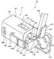
도1은 본 발명의 실시예에 따른 광 커넥터의 사시도이다.1 is a perspective view of an optical connector according to an embodiment of the present invention.
도2는 도1의 광 커넥터의 분해 사시도이다.Figure 2 is an exploded perspective view of the optical connector of Figure 1;
도3은 도1의 광 커넥터를 갖는 본 발명의 실시예에 따른 커넥터 부착 광 섬유의 사시도이다.3 is a perspective view of an optical fiber with a connector according to an embodiment of the present invention having the optical connector of FIG.
도4a 및 도4b는 도3의 커넥터 부착 광 섬유의 수직 단면도로서, 도4a는 정렬 슬리브 부재가 부착된 상태를 도시하고, 도4b는 정렬 슬리브 부재가 분리된 상태를 도시하는 도면이다.4A and 4B are vertical sectional views of the optical fiber with connector of FIG. 3, FIG. 4A shows a state in which the alignment sleeve member is attached, and FIG. 4B shows a state in which the alignment sleeve member is detached.
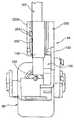
도5는 본 발명의 다른 실시예에 따른 광 커넥터의 사시도이다.5 is a perspective view of an optical connector according to another embodiment of the present invention.
도6은 도5의 광 커넥터의 수직 단면 사시도이다.6 is a vertical sectional perspective view of the optical connector of FIG.
도7은 도5의 광 커넥터를 갖는 본 발명의 다른 실시예에 다른 커넥터를 구비한 광 섬유의 사시도이다.Figure 7 is a perspective view of an optical fiber with a connector according to another embodiment of the present invention with the optical connector of Figure 5;
도8은 도7의 커넥터 부착 광 섬유의 수직 단면 사시도이다.Fig. 8 is a vertical sectional perspective view of the optical fiber with connector of Fig. 7.
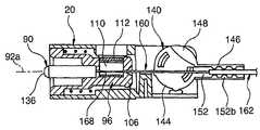
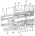
도9는 도1 및 도5의 광 커넥터를 구비한 본 발명의 실시예에 따른 광 섬유 접속 장치의 사시도이다.Fig. 9 is a perspective view of an optical fiber connecting device according to an embodiment of the present invention with the optical connectors of Figs. 1 and 5;
도10은 도9의 광 섬유 접속 장치의 사용시의 수직 단면 사시도이다.Fig. 10 is a vertical sectional perspective view of the optical fiber connecting device of Fig. 9 in use.
도11a 및 도11b는 도1의 광 커넥터에 부착된 페룰을 도시하는 도면으로서, 도11a는 사시도, 도11b는 수직 단면도이다.11A and 11B show a ferrule attached to the optical connector of FIG. 1, FIG. 11A is a perspective view, and FIG. 11B is a vertical sectional view.
도12a 및 도12b는 도1의 광 커넥터에 부착된 정렬 슬리브 부재의 도면으로서, 도12a는 사시도, 도12b는 수직 단면도이다.12A and 12B are views of the alignment sleeve member attached to the optical connector of FIG. 1, FIG. 12A is a perspective view, and FIG. 12B is a vertical sectional view.
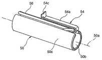
도13a는 도12a 및 도12b의 정렬 슬리브 부재의 슬롯 형성 슬리브 및 가동 셔터의 사시도이고, 도13b는 슬리브 유지 섹션의 수직 단면 사시도이다.Fig. 13A is a perspective view of the slotting sleeve and the movable shutter of the alignment sleeve member of Figs. 12A and 12B, and Fig. 13B is a vertical cross-sectional perspective view of the sleeve holding section.
도14a는 도3의 커넥터 부착 광 섬유의 광 섬유 코드의 도면이고, 도14b는 도7의 커넥터 부착 광 섬유의 광 섬유 케이블의 도면이다.FIG. 14A is a view of the optical fiber cord of the optical fiber with connector of FIG. 3, and FIG. 14B is a view of the optical fiber cable of the optical fiber with connector of FIG.
도15a 및 도15b는 도5의 광 커넥터에 부착된 섬유 고정 부재 및 작동 부재의 도면으로서, 도15a는 사시도, 도15b는 정면도이다.15A and 15B are views of the fiber fixing member and the operation member attached to the optical connector of FIG. 5, FIG. 15A is a perspective view, and FIG. 15B is a front view.
도16a 및 도16b는 도5의 광 커넥터에 부착된 유지 섹션의 작동의 설명도로서, 도16a는 기능 위치를 도시하고, 도16b는 비기능 위치를 도시하는 도면이다.16A and 16B are explanatory views of the operation of the holding section attached to the optical connector of Fig. 5, in which Fig. 16A shows the functional position and Fig. 16B shows the non-functional position.
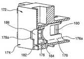
도17a 및 도17b는 도9의 광 섬유 접속 장치에 사용될 수 있는 어댑터의 도면으로서, 도17a는 사시도, 도17b는 수직 단면 사시도이다.17A and 17B are views of an adapter that can be used in the optical fiber connecting device of FIG. 9, FIG. 17A is a perspective view, and FIG. 17B is a vertical cross-sectional perspective view.
도18은 하부 어댑터 부재에 부착된 상태의 도9의 광 섬유 접속 장치를 도시하는 사시도이다.Fig. 18 is a perspective view showing the optical fiber connecting device of Fig. 9 attached to the lower adapter member.
도19는 도17a 및 도17b의 어댑터 부재에 부착된 상태의 도9의 광 섬유 접속 장치를 도시하는 수직 단면 사시도이다.FIG. 19 is a vertical sectional perspective view showing the optical fiber connecting device of FIG. 9 attached to the adapter member of FIGS. 17A and 17B.
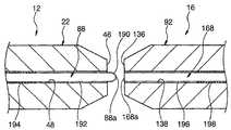
도20a 및 도20b는 본 발명에 따른 광 섬유 접속 방법이 적용되는 페룰과 함께 한 쌍의 광 섬유를 도시하는 수직 단면도로서, 도20a는 접속 전의 상태를 도시 하고, 도20b는 접속 후의 상태를 도시하는 도면이다.20A and 20B are vertical sectional views showing a pair of optical fibers together with a ferrule to which the optical fiber connecting method according to the present invention is applied, and FIG. 20A shows a state before connection, and FIG. 20B shows a state after connection. It is a figure.
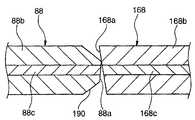
도21a 및 도21b는 접속 후의 상태에서의 광 섬유의 쌍을 도시하는 수직 단면도로서, 도21a는 도20a 및 도20b의 광 섬유를 도시하고, 도21b는 비교예의 광 섬유를 도시하는 도면이다.21A and 21B are vertical sectional views showing pairs of optical fibers in a state after connection, FIG. 21A shows the optical fibers of FIGS. 20A and 20B, and FIG. 21B shows the optical fibers of the comparative example.
도22는 기능 위치에서의 변형된 유지 섹션을 포함하는 도5의 광 커넥터를 도시하는 사시도이다.FIG. 22 is a perspective view illustrating the optical connector of FIG. 5 including a deformed holding section in a functional position. FIG.
도23은 비기능 위치에서의 도22의 광 커넥터를 도시하는 사시도이다.Fig. 23 is a perspective view showing the optical connector of Fig. 22 in the non-functional position.
도24는 도22의 광 커넥터를 화살표 24로부터 도시하는 단부도이다.FIG. 24 is an end view showing the optical connector of FIG. 22 from
이하, 본 발명의 실시예가 첨부 도면을 참조하여 상세히 설명될 것이다. 도면 전체에 걸쳐, 대응 부품은 공통의 도면 부호가 할당된다.Hereinafter, embodiments of the present invention will be described in detail with reference to the accompanying drawings. Throughout the drawings, corresponding parts are assigned common reference numerals.
도1 및 도2는 본 발명의 실시예에 따른 플러그형 광 커넥터(10)를 도시하는 도면이고, 도3 및 도4a 및 도4b는 광 커넥터를 구비한 본 발명의 실시예에 따른 광 섬유(12)를 도시하는 도면이고, 도5 및 도6은 본 발명의 다른 실시예에 따른 소켓형 광 커넥터(14)의 도면이고, 도7 및 도8은 광 커넥터(14)를 구비한 본 발명의 다른 실시예에 따른 광 섬유(16)를 도시하는 도면이고, 도9 및 도10은 플러그형 광 커넥터(10) 및 소켓형 광 커넥터(14)를 구비한 본 발명의 실시예에 따른 광 섬유 접속 장치(18)의 도면이다. 광 커넥터(10, 14) 및 광 섬유 접속 장치(18)는, 전방 단부면이 그로부터 코팅이 제거되어 있는 상태로 서로 동축상으로 접경하게 된 한 쌍의 코팅된 광 섬유를 접속할 수 있다.1 and 2 show a plug type
도1 내지 도4b에 도시된 바와 같이, 본 발명의 실시예에 따른 플러그형 광 커넥터(10)는 코팅된 광 섬유를 포함하는 광 전송 라인 부재의 단부에 부착되어 사용되고, 본체(20), 본체(20)의 소정 위치에 고정 설치되는 페룰(22) 및 본체(20) 상의 페룰(22)에 대해 소정 위치에서 지지되는 정렬 슬리브 부재(24)로 구성된다. 본체(20)는 페룰(22)을 고정 지지하는 중공 원통형 플러그 하우징(26)과 축방향으로 그에 인접하여 플러그 하우징(26)에 고정 연결되는 중공 원통형 부트(boot)(28)를 구비한다. 플러그 하우징(26) 및 부트(28)는 적합한 플라스틱 재료로 제조될 수 있다.As shown in Figs. 1 to 4B, the pluggable
본체(20)의 플러그 하우징(26)은 축방향으로 일 단부에서 개방된 사실상 원통형인 제1 부분(30)과 축방향으로 다른 단부에서 개방된 사실상 원통형인 제2 부분(32)을 일체로 구비한다. 제1 부분(30)은 그 원통형 내주면에 의해 제1 리세스(30a)를 형성하고, 반면 제2 부분(32)은 그 원통형 내주면에 의해 제2 리세스(32a)를 형성한다. 제1 리세스(30a) 및 제2 리세스(32a)는 제1 및 제2 부분(30, 32)과 일체로 형성되어 이들을 연통하는 중심 관통 구멍을 갖는 링형 벽(34)이 이들 사이에 형성되어 있다. 링형 벽(34)의 중심 관통 구멍은 제1 리세스(30a)측의 대직경 원통형 삽입 구멍(34a), 제2 리세스(32a)측에 절두 원추형으로 팽창하는 가이드 홈(34b) 및 삽입 구멍(34a) 및 가이드 홈(34b)을 연통하는 소직경 원통형 관통 구멍(34c)을 구비한다. 제1 리세스(30a), 제2 리세스(32a), 삽입 구멍(34a), 가이드 홈(34b) 및 관통 구멍(34c)은 서로 동축상으로 정렬된다.The
플러그 하우징(26)의 제1 부분(30)은 개방 단부(30b)에 인접하여 직경 방향 으로 대면 위치에 한 쌍의 결합 구멍(36)을 가지고 형성된다. 결합 구멍(36) 및 개방 단부(30b)는 제1 부분(30)의 내주면에 인접하는 가이드면(36a)을 이들 사이에 구비한다. 플러그 하우징(26)의 제1 부분(30)은, 플러그 하우징(26)의 외부에 제2 부분(32)에 도달하는 길이를 가지고 외팔보 방식으로 연장되는 개방 단부(30)에 인접하여 일체로 형성된 기부 단부(38a)를 갖는 크랭크형 래치 레버(38)를 추가로 갖는다. 래치 레버(38)는 플러그 하우징(26)에 접근하고 그로부터 이격하여 이동하는 방향으로 제1 부분(30) 상에서 전후방으로 이동 가능하도록 기부 단부(38a) 둘레로 탄성적으로 만곡된다. 종방향에서의 래치 레버(38)의 근사 중심은 한 쌍의 결합 리세스(38b)를 갖는 그 두 개의 측면 에지에 형성된다.The
본체(20)의 부트(28)는 축방향으로 일 단부에서 개방된 사실상 원통형인 제1 부분(40) 및 축방향으로 다른 단부에서 개방된 사실상 원통형인 제2 부분(42)을 일체로 구비한다. 제1 부분(40)은 그 원통형 내주면에 의해 제1 리세스(40a)를 형성하고, 반면 제2 부분(42)은 그 원통형 내주면에 의해 제2 리세스(42a)를 형성한다. 제1 리세스(40a) 및 제2 리세스(42a)는 약간의 단차를 통해 동축상으로 연통한다. 부트(28)의 제1 부분(40)은 가압 끼워맞춤 또는 접착에 의해 플러그 하우징(26)의 제2 부분(32) 및 제1 리세스(40a)를 고정 유지한다. 부트(28)의 제2 부분(42)은 제1 리세스(40a)에 유지된 플러그 하우징(26)의 제2 부분(32)의 제2 리세스(32a)와의 제2 리세스(42a)의 연통 상태를 유지하면서 외력에 의해 비교적 용이하게 만곡하기 위한 가요성을 갖는다. 부트(28)의 제2 부분(42)은 일정한 만곡 형상을 유지하기 위한 가요성 와이어(44)를 그 내부에 구비한다.The
도11a 및 도11b에 단독으로 도시된 바와 같이, 광 커넥터(10)의 페룰(22)은 그 중심축(22a)을 따라 섬유를 유지하기 위한 일 관통 구멍을 가지고 형성된 원통형 부재이다. 전체적으로, 이는 원통형 외주면(22b)을 갖는 단일-섬유 중심 설정부로서 기능한다. 페룰(22)은 중심축(22a)과 사실상 수직으로 편평하게 연장되는 축방향의 일 단부에 있는 접경 단부면(46)과 접경 단부면의 중심에서 개방되어 중심축(22a)을 따라 직선으로 연장되는 섬유 유지 채널(48)을 구비한다. 접경 단부면(46)은 테이퍼면(22c)을 통해 원통형 외주면(22b)과 연통한다. 섬유 유지 채널(48)은 접경 단부면(46)에 대향 측면에서 테이퍼진 가이드면(48a)에 의해 팽창되고 축방향으로 다른 단부에서 링형 단부면(22d)에서 개방한다.As shown alone in Figs. 11A and 11B, the
페룰(22)은 가압 끼워맞춤 또는 접착에 의해 링형 단부면(22d) 부근의 부분에서 플러그 하우징(26)의 링형 벽(34)의 삽입 구멍(34a)에 고정된다. 이 상태에서, 페룰(22)의 주 길이부는 플러그 하우징(26)의 제1 부분(30)의 제1 리세스(30a) 내에 간극을 가지고 사실상 동축상으로 배열된다. 또한, 페룰(22)의 접경 단부면(46)은 플러그 하우징(26)의 제1 부분(30)의 개방 단부(30b)로부터 약간 돌출되어 위치된다. 페룰(22)은 세라믹, 플라스틱, 금속 등으로 제조될 수 있다.The
광 커넥터(10)의 정렬 슬리브 부재(24)는, 도12a 내지 도13b에 도시된 바와 같이, 중공 원통형 슬롯 형성 슬리브(50), 슬롯 형성 슬리브(50)를 유지하는 중공 원통형 슬리브 홀더(52) 및 슬리브 홀더(52)에 의해 지지되고 슬롯 형성 슬리브(50) 내로 연장되는 가동 셔터(54)를 구비한다. 정렬 슬리브 부재(24)의 슬롯 형성 슬리브(50)는 원통형 형상으로 만곡된 금속 박판 또는 다른 탄성 박판 부재로 구성되고, 균일한 내주면(50b) 및 중심축(50a)을 형성하는 전체 부분에서의 외주면(50c)을 가지고, 내주면(50b) 및 외주면(50c)의 주연 방향으로 일 위치에서 축방향으로 전체 길이에 걸쳐 연장되는 슬릿(56)을 갖는다. 슬롯 형성 슬리브(50)는 그 자신의 탄성 복원력 하에서 내주면(50b)에 의해 형성된 보어(58)의 내경으로 균일하게 팽창하고 수축될 수 있다.The
정렬 슬리브 부재(24)의 슬리브 홀더(52)는 축방향으로 일 단부에서 개방된 사실상 원통형인 제1 부분 및 축방향으로 다른 단부에서 개방된 사실상 원통형인 제2 부분(62)을 구비한다. 제1 부분(60)은 그 원통형 내주면에 의해 제1 리세스(60a)를 형성하고, 반면 제2 부분(62)은 그 원통형 내주면에 의해 제2 리세스(62)를 형성한다. 제1 리세스(60a) 및 제2 리세스(62a)는 동일한 내경을 가지고, 일정한 단차 없이 서로 연통한다. 슬리브 홀더(52)의 제1 부분(60)은 후술하는 바와 같이, 본체(20)의 외부에서 플러그 형상으로 돌출하고 광 커넥터(10) 및 그 대응 커넥터[예를 들면, 광 커넥터(14)]의 접속시에 대응 커넥터의 소켓형 결합 섹션과 상보적으로 결합하는 대응 커넥터 결합 섹션으로서 기능한다.The
슬리브 홀더(52)의 제1 부분(60)은 그 개방 단부(60b)에 인접하는 테이퍼진 가이드면(64a)을 갖는 링형 리지(64)를 갖는다. 링형 플랜지(66)가 개방 단부(60b)로부터 이격된 위치에서 직경 방향으로 외측으로 돌출되어 제공된다. 유사하게, 제2 부분(62)은 직경 방향에서 내향으로 돌출되어 제공된 그 개방 단부(62b)에 인접하는 테이퍼진 가이드면(68b)을 갖는 링형 리지(68)를 구비한다. 링형 플랜지(70)가 개방 단부(62b)로부터 이격된 위치에 직경 방향으로 외측으로 돌출되어 제공된다. 예시된 실시예에서, 제1 부분(60) 및 제2 부분(62)은 개별 부재로서 제조되고, 링형 플랜지(66, 70)가 서로 인접하게 되는 위치 관계로 조합된다.The
슬리브 홀더(52)의 제2 부분(62)은, 링형 플랜지(70) 상의 직경 방향으로 대면 위치에 일체 형성된 기부 단부(72a)를 가지고 제2 부분(62)의 외주면을 따라 외팔보 방식으로 연장되는 한 쌍의 결합편(72)을 추가로 갖는다. 결합편(72)은 제2 부분(62) 상의 슬리브 홀더(52)에 접근하고 그로부터 이격되는 방향으로 전후방으로 이동하도록 기부 단부(72a) 둘레로 탄성 만곡될 수 있다. 종방향에서의 결합편(72)의 근사 중심은 이들의 외부면에 결합 돌출부(72b)를 가지고 형성된다. 슬리브 홀더(52)는 적합한 간극을 가지고 제1 및 제2 부분(60)의 제1 및 제2 리세스(60a, 62a)에 비적재 상태로 슬롯 형성 슬리브(50)를 유지한다. 이 때, 슬롯 형성 슬리브(50)는 제1 및 제2 리세스(60a, 62a)로부터 분리되지 않도록 제1 및 제2 부분(60, 62)의 링형 리지(64, 68)에 의해 유지된다. 슬리브 홀더(52)는 적합한 플라스틱 재료로 제조될 수 있다는 것을 주목해야 한다.The
정렬 슬리브 부재(24)의 가동 셔터(54)는 대략 J-형상으로 만곡된 금속 박판 또는 다른 탄성 박판 부재로 구성되고, 직선으로 연장되는 지지부(54a) 및 지지부(54a)보다 다소 짧게 만곡되어 연장되는 아암부(54b)를 갖는다. 가동 셔터(54)는, 지지부(54a)의 단부에 형성되고 슬리브 홀더(52)의 제1 부분(60)과 제2 부분(62) 사이에 고정 파지된 부착편(54c)을 갖는다. 이는 지지부(54a)가 제1 부분(60)의 내주면을 따라 축방향으로 연장된 상태로 슬리브 홀더(52)에서 외팔보 방식으로 지지된다. 이 상태에서, 가동 셔터(54)의 아암부(54b)는 보어(58) 내로 연 장하도록 슬롯 형성 슬리브(50)의 슬릿(56)에 접근하고 그로부터 이격하는 방향으로 전후방으로 이동하도록 지지부(54a)와 접속된 위치에 대해 탄성적으로 만곡될 수 있다. 즉, 가동 셔터(54)의 아암부(54b)는 슬롯 형성 슬리브(50)의 보어(58)에 수동적으로 변위 가능하게 설치된다.The
정렬 슬리브 부재(24)는 본체(20)의 플러그 하우징(26)의 제1 부분(30)에 유지되는 슬리브 홀더(52)의 제2 부분(62)에 의해 본체(20)에 착탈 가능하게 부착된다. 이 때, 슬리브 홀더(52)의 제2 부분(62)이 플러그 하우징(26)의 제1 부분(30)의 제1 리세스(30a) 내에 삽입될 때, 슬리브 홀더(52)의 결합편(72)의 쌍은 제1 부분(30)의 대응 가이드벽(36a)에 의해 가압되고 직경 방향으로 내향으로 만곡된다. 마지막으로, 결합편(72)의 결합 돌출부(72b)는 제1 부분(30)의 대응 결합 구멍(36) 내에 스냅 결합된다. 이와 함께, 플러그 하우징(26)에 고정된 페룰(22)의 주 길이부는 슬리브 홀더(52)의 제2 부분(62)의 개방 단부(62b)를 통과하고, 슬롯 형성 슬리브(50)의 보어(58) 내에 삽입된다. 그 결과, 정렬 슬리브 부재(24)는 본체(20)의 플러그 하우징(26) 상의 적합한 위치에 배열된다.The
정렬 슬리브 부재(24)가 본체(20)에 대해 적합한 위치에 배열된 상태에서, 슬리브 홀더(52)의 제2 리세스(62a)에 사실상 대응하는 길이의 슬롯 형성 슬리브(50)의 보어(58)의 부분은 접경 단부면(46)에 인접하는 페룰(22)의 일정한 길이를 유지한다. 이 상태에서, 슬롯 형성 슬리브(50)는 페룰(22)의 원통형 외주면(22b)에 접촉하고 탄성적으로 압박되어 약간 개방된다. 페룰(22)은 그 탄성 복원력에 의해 소정 위치에 중심 설정되어 지지된다. 즉, 이 상태에서, 페룰(22)의 중심축(22a)은 슬롯 형성된 슬리브(50)의 중심축(50a)과 정밀하게 정합하여 고정 배열되고 슬롯 형성 슬리브(50)는 페룰(22)에 대해 미리 정해진 중심 설정 위치에 지지된다.With the
또한, 이 적합한 부착 위치에서, 정렬 슬리브 부재(24)의 가동 셔터(54)는, 아암부(54b)의 단부(54d)가 페룰(22)의 접경 단부면(46)으로부터 이격되어 이동되고 섬유 유지 채널(48)의 개구의 축방향으로 전방에서 중심축(22a) 상에 중첩된 상태로 배열된다. 따라서, 가동 셔터(54)는 슬리브 홀더(52)의 제1 부분(60)의 개방 단부(60b)와 페룰(22)의 접경 단부면(46) 사이의 슬롯 형성 슬리브(50)의 보어(58) 내로 돌출하는 아암부(54b)에 의해 개방 단부(60b)의 위치에 페룰(22)을 통해 방출된 광이 도달하는 것을 차단할 수 있다.In addition, at this suitable attachment position, the
본체(20)로부터 정렬 슬리브 부재(24)를 분리할 때, 슬리브 홀더(52)의 두 개의 결합편(72)의 결합 돌출부(72b)는 결합 돌출부(72b)와 결합 구멍(36) 사이의 스냅 결합을 해제하기 위해 플러그 하우징(26)의 제1 부분(30)의 외부로부터 결합 구멍(36) 내로 강제로 압박된다. 이 상태에서, 플러그 하우징(26)으로부터 정렬 슬리브 부재(24)를 견인함으로써, 슬롯 형성 슬리브(50)는 페룰(22)로부터 분리되고 정렬 슬리브 부재(24)는 본체(20)로부터 분리된다. 본체(20) 상에 정렬 슬리브 부재(24)를 고정 설치하기 위한 결합 돌출부(72b)와 결합 구멍(36)의 스냅 결합은 특정 도구를 사용하지 않고 수동으로 분리될 수 있다는 점에서 장점을 갖지만, 정렬 슬리브 부재(24)가 광 커넥터(10) 및 대응 커넥터[예를 들면, 광 커넥터(14)]의 접속/분리시에 본체(20)로부터 부주의하게 분리되지 않도록 하는 충분한 신뢰성을 갖는 것이 바람직하다.When detaching the
상기 플러그형 광 커넥터(10)는, 정렬 슬리브 부재(24)가 커넥터 부착 광 섬유(12)를 형성하도록 본체(20)에 부착된 상태로 코팅된 광 섬유(80)를 구비하는 광 섬유 코드(82)의 단부에 부착될 수 있다(도3 및 도4a 및 도4b). 여기서, 광 섬유 코드(82)는 도14a에 도시된 바와 같이, 코팅된 광 섬유(80)를 노출시키도록 단부의 소정 길이로부터 플라스틱 외피(84) 및 장력 보유 부재(도시되지 않음)를 제거함으로써, 광 섬유(88)를 노출시키도록 코팅된 광 섬유(80)의 전방 단부의 소정 길이로부터 코팅(86)을 제거함으로써, 그리고 적어도 페룰(22)의 섬유 유지 채널(48)에 사실상 대응하는 길이로 특정 절삭 도구에 의해 노출된 광 섬유(88)를 절삭함으로써 미리 단부 처리된다.The plug type
이와 같이 단부 처리된 광 섬유 코드(82)는 광 커넥터(10)의 본체(20)의 부트(28) 내에 삽입되고, 이에 의해 단부에서 노출된 광 섬유(88)가 가이드 홈(34b) 및 플러그 하우징(26)의 링형 벽(34)의 관통 구멍(34c)을 통과하고 섬유 유지 채널(48) 내로 제1 리세스(30a)에 고정 설치된 페룰(22)의 가이드면(48a)으로부터 통과된다. 또한, 광 섬유(88)의 축방향 단부면(88a)이 페룰(22)의 접경 단부면(46)에 인접하는 소정 위치에 도달할 때의 시점에서, 예를 들면 코팅된 광 섬유(80)의 코팅(86) 및 광 섬유(88) 중 적어도 하나는 페룰(22) 및 플러그 하우징(26)[관통 구멍(34c)] 중 적어도 하나에 접착제에 의해 고정되고, 광 섬유 코드(82)의 외피(84)는 플러그 하우징(26)의 제2 리세스(32a)에 접착제에 의해 고정된다. 이와 같이, 광 섬유 코드(82)의 단부가 광 커넥터(10)와 끼워지고, 이에 의해 커넥터 부 착 광 섬유(12)가 완성된다.The end-treated
상기 구조를 갖는 광 커넥터(10)는 접경 단부면(48)을 구비하는 본체(20)에 설치된 페룰(22)의 부분을 보어(58) 내에 유지하는 정렬 슬리브 부재(24)를 구비하고, 따라서 페룰(22)의 접경 단부면(48) 상의 오염의 적층 및 손에 의한 접촉을 미리 방지하는 것이 가능하다. 정렬 슬리브 부재(24)는 본체(20)에 부착되고 그로부터 분리될 수 있으므로, 페룰(22)을 둘러싸는 영역이 세척되지 않을 때, 본체(20)로부터 정렬 슬리브 부재(24)를 분리함으로써 세척이 용이하다. 이들 작용 및 효과는 가동 셔터(54)가 제공되지 않을 때에도 나타난다는 것을 주목해야 한다.The
또한, 광 커넥터(10)에 따르면, 정렬 슬리브 부재(24)는 가동 셔터(54)를 구비하고, 따라서 광 커넥터(10)가 코팅된 광 섬유(80)에 부착된 상태에서 다른 광 커넥터와 접속하지 않으면, 광 섬유(88)로부터 페룰을 통해 방출된 광이 플러그 하우징(26)의 개방 단부(30b)로부터 외측으로 누출되는 것이 가동 셔터(54)에 의해 신뢰적으로 방지된다. 가동 셔터(54)는 정렬 슬리브 부재(24)의 보어(58) 내에 설치되고, 따라서 가동 셔터(54)의 부주의한 작동 위험이 없다. 또한, 페룰(22)에 지지된 정렬 슬리브 부재(24)는 가동 셔터(54)를 구비하기 때문에, 광 커넥터의 외부 형상에 무관하게 광 차단 기능을 용이하게 부여하는 것이 가능하다. 이와 같이, 광 커넥터(10)는 우수한 오염 방지 기능 및 광 차단 기능을 갖는다.Further, according to the
또한, 상기 구조를 갖는 커넥터 부착 광 섬유(12)는 광 커넥터(10)의 우수한 오염 방지 기능 및 광 차단 기능을 갖는다. 따라서, 커넥터 부착 광 섬유(12)는 고도의 안전성을 나타내고 일반 가정과 같은 열악한 지식 및 숙련도를 갖는 사용자 에게 조차 높은 안전성 및 신뢰성을 가지고 광 전송 라인의 형성에 기여할 수 있다. 광 커넥터(10)는 멀티-섬유 광 커넥터를 형성하기 위해 복수의 페룰(22) 및 페룰(22)에 대응하는 복수의 정렬 슬리브 부재(24)를 구비할 수 있다는 것을 주목해야 한다.In addition, the
도5 내지 도8에 도시된 바와 같이, 본 발명의 다른 실시예에 따른 소켓형 광 커넥터(14)는 코팅된 광 섬유를 포함하는 광 전송 라인 부재의 단부에 부착되어 사용되고, 본체(90), 본체(90)의 소정 위치에 설치된 페룰(92) 및 페룰(92)에 부착된 코팅된 광 섬유를 갖는 광 전송 라인 부재를 고정 유지하기 위한 유지 섹션(94)으로 구성된다. 본체(90)는 페룰(92)을 고정 지지하기 위한 원통형 소켓 블록(96)과 축방향으로 변위 가능하게 소켓 블록(96)을 지지하기 위한 중공 원통형 소켓 하우징(98)을 구비한다. 소켓 블록(96) 및 소켓 하우징(98)은 적합한 플라스틱 재료로 제조될 수 있다.5 to 8, the socket-type
본체(90)의 소켓 블록(96)은 축방향으로 일 단부에서 개방된 사실상 원통형인 제1 부분(100)과 축방향으로 다른 단부에서의 측면에서 개방된 원통형 제2 부분(102)을 일체로 구비한다. 제1 부분(100)은 그 원통형 내주면에 의해 제1 리세스(100a)를 형성하고, 반면 제2 부분(102)은 사실상 블록 형상의 내주면에 의해 제2 리세스(102a)를 형성한다. 제1 리세스(100a) 및 제2 리세스(102a)는 제1 및 제2 부분(100, 102)과 일체로 형성된 이들 두 개의 부분을 통과하는 중심 관통 구멍을 갖는 링형 벽(104)을 이들 사이에 갖는다. 링형 벽(104)의 중심 관통 구멍은 제1 리세스(100a)측의 대직경 원통형 삽입 구멍(104a) 및 제2 리세스(102a)측의 소직경 원통형 관통 구멍(104)을 구비한다. 제2 부분(102)은, 제2 리세스(102a)와 연통하는 중심 관통 구멍을 가지고 소켓 블록(96)의 축방향으로 다른 단부에 설치된 후방 단부벽(106)을 추가로 구비한다. 후방 단부벽(106)의 중심 관통 구멍은 제2 리세스(102a)측에서 소직경 원통형 관통 구멍(106a) 및 외부면을 향해 절두 원추형으로 팽창하는 가이드 홈(106b)을 포함한다. 제1 리세스(100a), 삽입 구멍(104a), 관통 구멍(104b), 관통 구멍(106a) 및 가이드 홈(106b)은 서로 동축상으로 정렬된다.The
소켓 블록(96)의 제1 부분(100)은 개방 단부(100b)에 인접하는 직경 방향으로 외측으로 돌출하는 링형 플랜지(108)를 가지고 형성된다. 또한, 링형 플랜지(108)의 소정 위치는 직경방향으로 국부적으로 외측 돌출하는 비틀림 정지부(108b) 및 계지부(108a)를 가지고 형성된다. 소켓 블록(96)의 제2 부분(102)은 그 코팅이 박리된 광 섬유를 고정 파지하는 개방/폐쇄 가능 섬유 고정 부재(110) 및 섬유 고정 부재(100)가 제2 리세스(102a)에 적합하게 개방 및 폐쇄 조합되도록 작동하는 작동 부재(112)를 유지한다.The
도15a 및 도15b에 도시된 바와 같이, 섬유 고정 부재(110)는 알루미늄 또는 다른 연성 재료로부터 미리 정해진 형상으로 형성된 박판 부재(sheet material)로 그 중심축을 따라 두 부분으로 절첩되는 모드를 갖는다. 절첩된 섬유 고정 부재(110)는 절첩부를 따라 버터플라이 에지(110a)를 가로질러 서로 대면하여 배열된 한 쌍의 플랩(114)을 구비한다. 이들 플랩(114)의 대면 표면은 광 섬유를 고정 파지하는 개방/폐쇄 가능 파지면(114a)을 가지고 형성된다. 예시된 실시예에서, 두 개의 플랩(114)의 파지면(114a)의 대응 위치는 버터플라이 에지(110a)에 평행한 소 정 위치에서 광 섬유를 파지하기 위한 직선형 지지 홈(116)(예를 들면, V-단면 홈)을 가지고 형성된다.As shown in Figs. 15A and 15B, the
섬유 고정 부재(110)의 플랩(114) 쌍은 버터플라이 에지(110a)의 영역에서 재료의 탄성 변형과 함께 버터플라이 에지(110a)에 대해 전후방으로, 즉 개방 및 폐쇄하여 이동하도록 설계된다. 일반적으로, 섬유 고정 부재(110)는 두 개의 플랩(114)이 파지면(114a)으로부터 다소 이격되어 이동하는 개방 위치에 배치된다(도15a 및 도15b). 개방 위치로부터, 이들을 더 근접하게 브릿지 연결(bridging)하는 방향에서 두 개의 플랩(114)에 외력을 인가함으로써, 부재는 파지면(114a)이 접촉하게 되는 폐쇄 위치로 버터플라이 에지(110a)의 탄성 복원력에 대항하여 변위한다. 섬유 고정 부재(110)가 개방 위치에 있을 때, 지지 홈(116)에 대한 광 섬유의 원활한 삽입 및 제거가 허용되고, 반면 섬유 고정 부재(110)가 폐쇄 위치에 있을 때는, 한 쌍의 지지 홈(116) 사이에 유지된 광 섬유가 단단히 고정 파지되어 두 개의 파지면(114a)으로부터 압력을 수용한다. 섬유 고정 부재(110)는 두 개의 지지 홈(116) 사이에 코팅을 가지고 광 섬유를 고정 파지하기 위해 지지 홈(116)의 폭을 적절하게 조정하여 형성될 수 있다는 것을 주목해야 한다.The pair of
작동 부재(112)는 예를 들면 플라스틱 재료의 일체 성형편으로 제조된 덮개형 부재이고, 섬유 고정 부재(110)의 두 개의 플랩(114)을 유지하는 것이 가능한 치수의 리세스(118)를 형성하는 한 쌍의 유지벽(120)을 구비한다. 이들 유지벽(120)은 미리 정해진 공간을 가로질러 사실상 평행하게 서로 대면하고 리세스(118)의 개방(도면에서, 저부)측의 1차 가압면(120a) 및 리세스(118)의 내부측의 2차 가압면(120b)을 갖는 단차형 표면으로서 형성된 대면 표면을 갖는다. 따라서, 리세스(118)는 두 개의 1차 가압면(120a)에 의해 형성된 비교적 넓은 개방측 영역 및 두 개의 2차 가압면(120b)에 의해 형성된 비교적 좁은 내부측 영역을 가지고 형성된다.The actuating
섬유 고정 부재(110)는 상기 개방/폐쇄 작동을 가능하게 하는 상태로 내부측에 대면하는 버터플라이 에지(110a)를 갖는 소켓 블록(96)의 제2 부분(102)의 제2 리세스(102a)에 고정된다. 소켓 블록(96)의 제2 리세스(102a)의 적합한 위치에 섬유 고정 부재(110)를 고정하면, 두 개의 지지 홈(116)이 소켓 블록(96)의 관통 구멍(104b, 106b)의 쌍에 대해 동축상으로 배열되는 것이 가능하도록 배열된다. 작동 부재(112)는 소켓 블록(96)의 제2 부분(102)의 개방 영역을 상보적으로 폐색하도록 제2 리세스(102a)에 이동 가능하게 부착된다. 이 때, 작동 부재(112)는 리세스(118) 내에 섬유 고정 부재(110)의 두 개의 플랩(114)을 유지한다. 두 개의 유지벽(120)은 가압면(120a, 120b)에 의해 스테이지에서 외부로부터 이들을 유지함으로써 두 개의 플랩(114)을 지지한다. 임시 부착 위치(도6 및 도8)로부터 소켓 블록(96)에 대한 최종 부착 위치에 대해 이동하는 동안, 작동 부재(112)는 파지면(114a)을 폐쇄 접촉하여 브릿지 연결하는 방향으로 두 개의 유지벽(120)으로부터 섬유 고정 부재(110)의 두 개의 플랩(114)에 압력을 인가함으로써 개방 위치로부터 폐쇄 위치로 섬유 고정 부재(110)를 변위시키도록 작동한다.The
본체(90)의 소켓 하우징(98)은 축방향으로 일 단부에서 개방된 원통형 제1 부분(122)과 축방향으로 다른 단부에서 개방된 원통형 제2 부분(124)과 일체로 제 공된다. 제1 부분(122)은 그 원통형 내주면에 의해 제1 리세스(122a)를 형성하고, 반면 제2 부분(124)은 그 원통형 내주면에 의해 제2 리세스(124a)를 형성한다. 제1 리세스(122a) 및 제2 리세스(124a)는 단차[숄더(126)]를 통해 동축상으로 서로 연통한다. 소켓 하우징(98)은 제1 부분(122)의 제1 리세스(122a) 내에 소켓 블록(96)의 제1 부분(100)을 축방향으로 변위 가능하게 유지하고, 제2 부분(124)의 제2 리세스(124a) 내에 소켓 블록(96)의 제2 부분(102)을 축방향으로 변위 가능하게 유지한다.The
소켓 하우징(98)의 제1 리세스(122a)는 소켓 블록(96)의 제1 부분(100)을 둘러싸는 배열에 의해 압축 가능 상태로 소켓 블록(96)의 링형 플랜지(108)와 숄더(126) 사이에 개재된 압축 헬리컬 스프링(128)을 또한 유지한다. 압축 헬리컬 스프링(128)은 개방 단부(122)로부터 소켓 하우징(98)의 제1 부분(122)의 개방 단부(122b)로부터 이를 외측으로 압박하는 방향으로 소켓 블록(96)을 탄성적으로 편향한다. 또한, 소켓 하우징(98)의 제1 부분(122)은 개방 단부(122b)의 부근의 소정 위치에서 소켓 블록(96)의 링형 하우징(108)에 제공된 비틀림 정지부(108b) 및 계지부(108a)를 상보적으로 유지하는 복수의 리세스(130)를 가지고 형성된다. 이에 의해, 소켓 블록(96)은 압축 헬리컬 스프링(128)의 편향력 하에서 축방향으로만 미리 정해진 거리에 걸쳐 변위될 수 있다.The first recess 122a of the
소켓 하우징(98)의 제2 부분(124)은 소켓 블록(96)의 제2 부분(102)에 설치된 작동 부재(112)에 대응하는 위치에서 측면으로 개방된 작동 윈도우(132)를 가지고 형성된다. 작동 윈도우(132)는 상술한 임시 부착 위치로부터 최종 부착 위치로 작동 부재(112)를 이동시키기 위한 적절한 도구의 삽입을 허용한다. 소켓 하우징(98)의 제2 부분(124)은, 제1 부분(122)과의 경계 영역에서 외부면 상의 직경 방향으로 대면 위치에 일체로 형성되고 제2 부분(124)의 외부면을 따라 외팔보 방식으로 연장되는 기부 단부(134a)를 갖는 한 쌍의 래치 레버(134)를 추가로 갖는다. 래치 레버(134)는 제2 부분(124) 상에서 소켓 하우징(98)에 접근하고 그로부터 이격되는 방향으로 전후방 이동하도록 기부 단부(134a)에 대해 탄성적으로 만곡될 수 있다. 래치 레버(134)의 종방향에서의 근사 중심은 이들의 외부면에서 결합 돌출부(134b)를 가지고 형성된다.The
광 커넥터(14)의 페룰(92)은 광 커넥터(10)의 페룰(22)과 사실상 동일한 구조를 갖는다. 즉, 페룰(92)은 중심축(92)에 사실상 수직으로 편평하게 연장되는 축방향으로 일 단부에 있는 접경 단부면(136)과, 접경 단부면(136)의 중심에서 개방되고 중심축을 따라 직선으로 연장되는 섬유 유지 채널(138)을 구비한다. 접경 단부면(136)은 테이퍼면(92c)을 통해 원통형 외주면(92b)과 연통한다.The
페룰(92)은 가압 끼워맞춤 또는 접착에 의해 접경 단부면(136)에 대향 측면에서 링형 단부면(92d)에 인접한 부분에서 소켓 블록(96)의 링형 벽(104)의 삽입 구멍(104a)에 고정된다. 이 상태에서, 페룰(92)의 주 길이부는 공간과 사실상 동축상으로 소켓 블록(96)의 제1 부분(100)의 제1 리세스(100a)에 배열된다. 또한, 페룰(92)의 접경 단부면(136)은 소켓 블록(96)의 제1 부분(100)의 개방 단부(100b)로부터 약간 외측으로 돌출되어 위치된다.The
소켓 블록(96)에 고정된 페룰(92)은 소켓 블록(96)과 함께 소켓 하우징(98) 에 대해 축방향으로 미리 정해진 거리에 걸쳐 변위될 수 있다. 소켓 블록(96)이 압축 헬리컬 스프링(128)의 편향력에 의해 소켓 하우징(98)의 제1 부분(122)의 개방 단부(122b)측에 기대는 전방 단부 위치에서, 페룰(92)의 접경 단부면(136)은 소켓 하우징(98)의 개방 단부(122b)로부터 약간 외측으로 돌출되어 배열된다. 또한, 소켓 블록(96)이 압축 헬리컬 스프링(128)의 편향력에 대해 소켓 하우징(98)의 제2 부분(124)의 개방 단부(124b)측에 기대는 후방 단부 위치에서, 페룰(92)의 접경 단부면(136)은 소켓 하우징(98)의 개방 단부(122b)와 사실상 동일한 가상 평면 상에 배열된다. 이 구조에 의해, 다른 커넥터[예를 들면, 광 커넥터(10)]와의 광 커넥터(14)의 접속시에, 개별 제공 정렬 슬리브 부재[예를 들면, 광 커넥터(10)의 정렬 슬리브 부재(24)]에서, 두 개의 커넥터의 페룰의 접경 단부면을 압축 헬리컬 스프링(128)의 스프링 편향력에 의해 서로에 대해 접경하게 하고 고정확도로 중심 설정된 코팅된 광 섬유의 쌍과 단부면 접경 상태로 이들을 접속하는 것이 가능하다.The
광 커넥터(14)의 유지 섹션(94)은, 본체(90)의 소켓 하우징(98)의 제2 부분(124)에 인접하는 위치에 배열되고 개방 단부(124)[또는 소켓 블록(96)에 고정된 페룰(92)의 링형 단부면(92d)]로부터 정확히 미리 정해진 거리만큼 분리된 유지 부재(140)를 구비한다. 유지 부재(140)는, 소켓 하우징(98)의 제2 부분(124)으로부터 제1 부분(122)에 대향하는 측면으로 일체로 연장되는 제3 부분(142) 상의 소켓 블록(96)에 고정된 페룰(92)의 중심축(92a)에 사실상 수직인 방향으로 연장되는 회전축(140a)을 가지고 회전 가능하게 제공된다. 대안적으로, 유지 부재(140)는 소켓 하우징(98)의 제3 부분(142)과 일체로(즉, 고정되어) 형성될 수 있다.The retaining
유지 부재(140)는 예를 들면 플라스틱 수지의 일체 성형편으로 구성되고, 회전축(140a) 상에 중심 설정된 디스크 형상을 갖는 기부 플레이트부(144) 및 방사상 형상으로 기부 플레이트부(144)로부터 외측으로 연장되는 U-형 연장부(146)를 구비한다. 유지 부재(140)의 기부 플레이트부(144)는 회전축(140a)을 구비하지 않는 사실상 궁형(bow-shaped) 영역에서 회전축 방향으로 돌출하는 팽윤부(bulge)(148)를 구비한다. 팽윤부(148)는, 광 커넥터(14)가 부착되는 코팅된 광 섬유에 대해 형성된 최소 곡률 반경보다 약간 큰 미리 정해진 곡률 반경만큼 원호형으로 외측으로 만곡 팽윤된 코팅된 섬유 가이드면(148a)을 회전축(140a)에서의 표면에 갖는다. 또한, 기부 플레이트부(144)는 팽윤부(148)에 대향하는 측면에서 미리 정해진 중심각 위치에서 외주면 상에 국부적으로 돌출하는 복수의 돌출부를 갖는다. 각각의 돌출부(144a)는 부품의 관련 그룹의 약간의 탄성 변형과 함께 소켓 하우징(98)의 제3 부분(142)의 소정 위치에 형성된 기부 시트(150) 상에 결합 홈(150a)에 끼워진다.The holding
유지 부재(140)의 연장부(146)는 직선 연장 상태로 광 전송 라인 부재를 유지하는 것이 가능한 유지 홈(152)을 가지고 형성된다. 유지 부재(152)는 기부 플레이트부(144)에 인접하는 그 기부 단부(152a)에서 팽윤부(148)의 코팅된 섬유 가이드면(148a)에 사실상 접속되고 원호형 코팅된 섬유 가이드면(148a)에 대해 사실상 접선 방향으로 연장한다. 또한, 유지 홈(152)은 광 전송 라인 부재의 외피와의 마찰에 의해 결합하는 복수의 돌출부(152b)를 갖는 연장부(146)의 내부면에서의 소정의 위치에 형성된다. 유지 부재(140)가 예시된 기능 위치에 있을 때, 연장 부(146)의 유지 홈(152)은 본체(90)의 소켓 블록(96)의 후방 단부벽(106)[또는 소켓 블록(96)에 고정된 페룰(92)의 링형 단부면(92d)]으로부터 볼 때 팽윤부(148)의 코팅된 섬유 가이드면(148a) 및 회전축(140a) 모두로부터 멀리 있는 위치에 배열되고, 소켓 블록(96)에 고정된 페룰(92)의 중심축[즉, 섬유 유지 채널(138)]에 대해 미리 정해진 각도만큼 경사진 방향으로 연장된다(도16a 참조). 또한, 이 기능 위치에서, 기부 플레이트부(144)의 팽윤부(148)의 코팅된 섬유 가이드면(148a)은 소켓 하우징(98)의 제3 부분(142)의 기부 시트(150)로부터 볼 때 회전축(140a)으로부터 멀리 있는 위치에 배열된다.The
유지 부재(140)에 제공된 유지 홈(152)은 상기 구조를 갖기 때문에, 본체(90)의 소켓 하우징(98) 상의 페룰(92)의 위치에 무관하게, 광 전송 라인 부재의 코팅된 광 섬유가 적어도 미리 정해진 최소 곡률 반경의 곡률 반경만큼 만곡되도록 기능한다. 이 코팅된 광 섬유의 만곡은 페룰(92)의 중심축(92a)에 대한 유지 홈(152)의 경사각 및 유지 홈(152)과 페룰(92) 사이의 거리에 기초한다. 또한, 팽윤부(148)의 코팅된 섬유 가이드면(148a)은 유지 홈(152)에 의해 만곡된 코팅된 광 섬유에 일반적으로는 접촉하지 않도록 부근의 위치에 형성된다. 코팅된 섬유 가이드면(148a)은 부주의한 외력에 기인하는 최소 곡률 반경보다 작은 곡률 반경만큼 만곡된 코팅된 광 섬유가 만곡되어 종료되는 것을 효과적으로 방지한다. 대안적으로, 코팅된 섬유 가이드면(148a)은 인장을 발생하지 않는 정도로 만곡된 코팅된 광 섬유에 약간 접촉함으로써 만곡 작용을 지원할 수 있다.Since the retaining
예시된 기능 위치에서, 유지 부재(140)의 기부 플레이트부(144)에 제공된 돌 출부(144a)는 소켓 하우징(98)의 기부 시트(150)의 결합 홈(150a)과 결합하고 유지 부재(140)의 부주의한 회전을 방해한다는 것을 주목해야 한다. 또한, 소켓 하우징(98)의 제3 부분(142)에 유지 부재(140)를 일체로 형성할 때, 기부 플레이트부(144) 및 연장부(146)는 예시된 기능 위치에서 미리 고정되어 배열된다.In the illustrated functional position, the protrusion 144a provided in the
본체(90)에 회전 가능하게 설치된 유지 부재(140)는, 연장부(146)의 유지 홈(152)이 소켓 블록(96)[또는 중심축(92a)의 연장부]에 고정된 페룰(92)의 중심축(92a)[즉, 섬유 유지 채널(138)]에 사실상 평행한 방향으로 본체(90)의 소켓 블록(96)의 후방 단부벽(106)으로부터 볼 때 팽윤부(148)의 코팅된 섬유 가이드면(148a) 및 회전축(140a) 모두로부터 멀리 있는 위치로 연장되는 비기능 위치에 배열될 수 있다(도16b 참조). 이 비기능 위치에서, 유지 부재(140)의 기부 플레이트부(144)에 제공된 다른 돌출부(144a)가 소켓 하우징(98)의 시트(150)의 결합 홈(150a)과 결합하고 유지 부재(140)의 부주의한 회전을 방해한다. 후술하는 바와 같이, 유지 부재(140)는 광 커넥터(14)를 광 전송 라인 부재에 부착할 때 기능 위치와 비기능 위치 사이에서 적합하게 회전된다.The holding
상술한 소켓형 광 커넥터(14)는 코팅된 광 섬유(160)를 포함하는 광 섬유 케이블(162)의 단부에 이를 부착함으로써 커넥터 부착 광 섬유(16)를 형성할 수 있다(도7 및 도8). 여기서, 이 광 섬유 케이블(162)은 도14b에 도시된 바와 같이, 코팅된 광 섬유(160)를 노출시키도록 단부의 소정 길이에 걸쳐 플라스틱 외피(164) 및 장력 보유 부재(도시되지 않음)를 제거함으로써, 광 섬유(168)를 노출시키도록 코팅된 광 섬유(160)의 전방 단부의 소정 길이에 걸쳐 코팅(166)을 제거함으로써, 페룰(92)의 섬유 유지 채널(138)에 적어도 사실상 대응하는 길이로 특정화 절삭 도구에 의해 노출된 광 섬유(168)를 절삭함으로써 미리 단부 처리된다.The socketed
이와 같이 단부 처리된 광 섬유 케이블(162)은 후방 단부벽(106)으로부터 광 커넥터(14)의 본체(90)의 소켓 블록(96) 내로 삽입된다. 이 때, 소켓 블록(96)의 제2 부분(102)에 설치된 작동 부재(112)는 상술한 임시 부착 위치에 배치되고, 여기서 섬유 고정 부재(110)는 개방 위치에 배치된다. 또한, 유지 섹션(94)의 유지 부재(140)는 상술한 비기능 위치에 배치된다.The
따라서, 광 섬유 케이블(162)의 전방 단부에서 노출된 광 섬유(168)는 소켓 블록(96)의 후방 단부벽(106)의 관통 구멍(106a) 및 가이드 홈(106b)을 통과하고, 섬유 고정 부재(110)의 지지 홈(116)의 쌍 사이를 통과하고, 소켓 블록(96)의 링형 벽(104)의 관통 구멍(104b)을 통과하고, 제1 리세스(100a)에 고정 설치된 페룰(92)의 섬유 유지 채널(138)을 통과한다. 또한, 광 섬유(168)의 축방향 단부면(168a)이 페룰(92)의 접경 단부면(136)에 인접하는 소정 위치에 도달할 때의 시점에, 작동 부재(112)는 폐쇄 위치로 섬유 고정 부재(110)를 변위시키고 지지 홈(116)의 쌍 사이에 광 섬유(168)[또는 코팅된 광 섬유(160)]를 단단히 파지하도록 임시 부착 위치로부터 최종 부착 위치로 압박된다.Accordingly, the
이와 같이 소켓 블록(96)에 광 섬유(168)를 고정한 후에, 광 섬유 케이블(162)은 외피(164) 내로 복수의 돌출부(152b)를 맞물리게 하면서 유지 부재(140)의 연장부(146)의 유지 홈 내에 삽입된다. 이 상태에서, 광 섬유 케이블(162)은 페룰(92)의 접경 단부면(136)으로부터 유지 홈(152)의 단부의 범위로 광 섬유(168) 가 정확히 연장된 상태로 유지된다(도16b). 다음에, 유지 부재(140)는 페룰(92)의 중심축(92a)에 대해 미리 정해진 각도만큼 경사진 위치에서 유지 홈(152)을 배열하도록 비기능 위치로부터 기능 위치로 회전된다.After fixing the
비기능 위치로부터 기능 위치로 회전되는 유지 부재(140)와 함께, 유지 부재(140)의 기부 플레이트부(144)를 따라 연장되는 코팅된 광 섬유(160)는 점진적으로 팽윤부(148)의 코팅된 섬유 가이드면(148a)에 접근한다. 또한, 유지 부재(140)가 기능 위치에 도달할 때, 코팅된 광 섬유(160)는 소켓 블록(96)의 후방 단부벽(106)으로부터 유지 홈(152)의 기부 단부(152a)로의 범위에서 상술한 바와 같이 팽윤부(148)의 코팅된 섬유 가이드면(148a)에 접근하여 만곡된다(도16a). 이 때, 코팅된 섬유 가이드면(148a)의 존재에 의해, 형성된 최소 곡률 반경의 값보다 작은 반경만큼 만곡하는 코팅된 광 섬유(160)가 신뢰적으로 회피된다. 또한, 광 섬유 케이블(162)은 소켓 블록(96)의 후방 단부벽(106)으로부터 볼 때 코팅된 섬유 가이드면(148a)으로부터 멀리 있는 위치에서 유지 홈(152)에 유지되기 때문에, 소켓 블록(96)이 상술한 바와 같이 소켓 하우징(98)에 대해 축방향으로 변위될 때, 코팅된 광 섬유(160)는 코팅된 섬유 가이드면에 접근하여 형성된 최소 곡률 반경보다 작은 반경에 도달하지 않는 범위로 약간 만곡되는 것이 허용된다. 이와 같이, 광 커넥터(14)는 광 섬유 케이블(162)의 단부에 부착되고, 이에 의해 커넥터 부착 광 섬유(16)가 완성된다.With the retaining
상기 구조를 갖는 광 커넥터(14)는 본체(90)에 설치된 페룰(92)을 유지하는 정렬 슬리브 부재를 구비하지 않는다. 또한, 페룰(92)의 후방에 적어도 형성된 최 소 곡률 반경의 값의 반경만큼 만곡되도록 부착될 코팅된 광 섬유(160)를 유지하는 것이 가능하고, 따라서 코팅된 광 섬유(160) 내의 광 손실을 억제하면서 사용시에 페룰(92)의 연장 방향에서의 외형 치수를 효과적으로 감소시킬 수 있다. 이 코팅된 광 섬유(160)의 만곡은 유지 섹션(94)에 제공된 유지 홈(152)에 대한 배열 예비 설정에 기초하고, 따라서 건설 현장에서 광 섬유 케이블(162)에 대한 커넥터 부착 작업을 수행할 때에도, 코팅된 광 섬유(160)에 광 커넥터를 신속하고 정확하게 부착하는 것이 가능하다. 연결된 유지 부재(140)로부터 유지 섹션(94)을 구성하면, 비틀림 또는 인장 또는 다른 응력이 코팅된 광 섬유(160)에 부주의하게 집중하는 것을 허용하지 않고 미리 정해진 곡률 반경만큼 코팅된 광 섬유(160)를 만곡시키는 것이 가능하고, 따라서 현장 커넥터 부착 작업이 현저하게 용이해진다.The
또한, 광 커넥터(14)에 따르면, 사용시에 소켓 블록(96)과 유지 홈(152) 사이의 코팅된 섬유 가이드면(148a)을 따라 만곡하여 연장되는 코팅된 광 섬유(160)는, 다른 커넥터[예를 들면, 광 커넥터(10)]와 광 커넥터(14)를 접속할 때 압축 헬리컬 스프링(128)의 편향력에 대해 축방향으로 후방으로 소켓 블록(96)이 이동할 때에도 코팅된 섬유 가이드면(148a)에 인접하여 형성된 최소 곡률 반경보다 작은 반경 이하의 범위로 약간 만곡될 수 있다. 따라서, 적은 접속 손실로 접속을 안정적으로 형성하는 것이 가능하다. 또한, 정렬 슬리브 부재를 구비하지 않은 광 커넥터(14)의 구조는 또한 페룰 주위의 영역의 세척을 용이하게 하는 효과를 갖는다. 또한, 페룰(92)과 광 섬유(168)는 소켓 블록(96)에 제공된 작동 부재(112) 및 섬유 고정 부재(110)의 작용에 의해 서로 고정되고, 따라서 접착제의 사용의 필요가 없 으며 현장 커넥터 부착 작업이 더 가속화될 수 있다. 이와 같이, 광 커넥터(14)는 페룰의 연장 방향에서의 외형 치수를 효과적으로 감소시킬 수 있고 또한 우수한 현장 시공 효율 및 안전성을 갖는다.In addition, according to the
또한, 상기 구조를 갖는 커넥터 부착 광 섬유(16)는 광 커넥터(14)의 외형 치수의 감소 효과 및 우수한 현장 시공 효율 및 안전성을 갖는다. 따라서, 커넥터 부착 광 섬유(16)는 공중 광 섬유 네트워크로부터 개인용 가정까지 광 섬유 케이블을 연장하고 위치하기 위한 인입 네트워크에서 가정의 벽 내부에 금속 파이프를 사용하여 위치된 광 섬유 케이블로서 특히 적합하게 사용될 수 있다. 이 용도에서, 소켓형 광 커넥터(14)는, 광 섬유 케이블(162) 내부의 광 손실을 억제하면서 실내의 소정 위치에 제공된 스위치박스 내의 충분한 공간 여유를 가지고 유지될 수 있다. 광 커넥터(14)에 제공된 유지 섹션(94)의 구조는 예시된 실시예에서와 같이 소켓형 광 커넥터의 것에 한정되지 않는다는 것을 주목해야 한다. 이는 또한 광 커넥터(10)와 같은 플러그형 광 커넥터에 제공될 수 있다. 또한, 광 커넥터(14)는 멀티-섬유 광 커넥터를 형성하기 위해 복수의 페룰(92)과 개별 페룰(92)에 대응하는 복수의 유지 섹션(94)을 구비할 수 있다.In addition, the
광 커넥터(14)에서, 유지 섹션(94)의 유지 부재(140)가 비기능 위치에 위치될 때, 유지 부재(140)의 연장부(146)의 유지 홈(152)에 끼워진 광 섬유 케이블(162)의 코팅된 광 섬유(160)는 본체(90)의 소켓 블록(96)의 후방 단부벽(106)까지 연장되는 노출된 길이에서 다소 만곡 상태에 있을 수 있음에 주목해야 한다. 이러한 만곡 상태가 허용될 때, 코팅된 광 섬유(160)가 비기능 위치로부터 기능 위 치로의 유지 부재(140)의 회전 중에 예측하지 않은 인장력을 받게 되는 것을 방지할 수 있다. 유지 부재(140)의 회전축(140a)의 위치 또는 광 섬유 케이블(162)의 코팅된 광 섬유(160)의 노출된 길이와 관련한 정확성에 대한 요구를 또한 유리하게 완화하는 것이 가능하다. 또한, 코팅된 광 섬유(160)가 만곡되면, 유지 부재(140)가 비기능 위치에 있을 때, 광 섬유(168)의 전체 노출된 길이가 소켓 블록(96) 내에 확실히 수용되므로, 본체(90)의 외부의 광 섬유(168)의 노출에 의한 단점을 효과적으로 회피하는 것이 가능하다.In the
상술한 플러그형 광 커넥터(10) 및 소켓형 광 커넥터(14)는, 도9 및 도10에 도시된 바와 같이, 광 섬유 접속 장치(18)를 형성하도록 착탈 가능하게 조합된다. 광 섬유 접속 장치(18)에서, 광 섬유 코드(82)의 단부에 부착된 광 커넥터(10) 및 광 섬유 케이블(162)의 단부에 부착된 광 커넥터(14)를 접속할 때, 광 커넥터(10)의 본체(20)에 부착된 정렬 슬리브 부재(24)의 슬리브 홀더(52)의 제1 부분은 광 커넥터(14)의 소켓 블록(96)의 제1 리세스(100a) 내에 삽입된다. 여기서, 정렬 슬리브 부재(24)의 제1 부분(60) 및 소켓 블록(96)의 제1 리세스(100a)는 덜걱거림 없이 상보적인 결합을 가능하게 하는 형상 및 치수를 갖도록 형성된다.The plug type
정렬 슬리브 부재(24)는 소켓 블록(96) 내에 삽입된다. 이와 함께, 광 커넥터(14)의 페룰(92)은 정렬 슬리브 부재(24)의 슬롯 형성 슬리브(50) 내의 접경 단부면(138)으로부터 삽입된다. 여기서, 두 개의 커넥터(10, 14)의 페룰(22, 92)을 동일 치수 및 형상으로 형성함으로써, 페룰(92)은 접경 단부면(138)에 인접하는 일정한 길이부가 슬리브 홀더(52)의 제1 부분(60)의 개방 단부(60b)를 통과하여 광 커넥터(10)의 페룰(22)의 접경 단부면(46)에 타격할 때까지 슬롯 형성 슬리브(50)의 보어(58) 내에 삽입된다(도10). 이 상태에서, 슬롯 형성 슬리브(50)는 그 내주면(50b)에서 페룰(92)의 원통형 외주면(92b)에 접촉하고 약간 넓게 탄성적으로 압박되어 그 탄성 복원력에 의해 소정 위치에서 페룰(92)을 중심 설정하고 지지한다. 따라서, 이 상태에서, 페룰(92)의 중심축(92a)은 슬롯 형성 슬리브(50)의 중심축(50a), 즉 페룰(22)의 중심축(22a)과 정확하게 정렬되어 고정 배열된다. 또한, 두 개의 페룰(22, 92)의 접경 단부면(46, 136)은 압축 헬리컬 스프링(128)의 편향력 하에서 서로에 대해 접촉하여 접경하게 되고, 이에 의해 두 개의 페룰(22, 92)에 고정된 광 섬유(88, 168)의 쌍은 접경 단부면이 고정확도로 중심 설정되어 접경하는 상태로 접속된다.The
광 커넥터(14)의 페룰(92)이 정렬 슬리브 부재(24)의 슬롯 형성 슬리브(50)의 보어(58) 내에 삽입되면, 슬롯 형성 슬리브(50)의 보어(58) 내에 수동적으로 변위 가능하게 배열된 가동 셔터(54)의 아암부(54b)는 그 단부(54d)에서 미리 페룰(92)에 타격하고 슬롯 형성 슬리브(50)의 슬롯(56) 내에 수동적으로 견인되도록 탄성적으로 만곡된다(도10). 따라서, 가동 셔터(54)는 페룰(22, 92)의 접경에 의해 광 섬유(88, 168)의 단부면 접경 및 접속과 간섭하지 않는다. 또한, 광 커넥터(10, 14)가 분리되면, 광 커넥터(14)의 페룰(92)은 정렬 슬리브 부재(24)의 슬롯 형성 슬리브(50)의 보어(58)로부터 외부로 견인된다. 이와 함께, 가동 셔터(54)의 아암부(54b)는 탄성적으로 복원되고 그 단부(54d)가 슬롯 형성 슬리브(50)의 보어(58) 내의 페룰(22)의 중심축(22a)의 연장부 상에 배열된다.Once the
상기 구조를 갖는 광 섬유 접속 장치(18)에서, 광 커넥터(10, 14) 및 상술한 커넥터 부착 광 섬유(12, 16)의 작용 및 효과는 상조적으로(synergistically) 작용한다. 특히, 장치는 실내에 위치된 광 전송 라인에 바람직하게 적용될 수 있다는 것을 이해할 수 있을 것이다. 본 발명에 따른 광 섬유 접속 장치 및 본 발명에 따른 광 커넥터 및 커넥터 부착 광 섬유에서, 압력 하에서 페룰의 쌍의 접경 단부면을 접경하여 브릿지 연결하기 위한 가동 페룰 구조[예시된 실시예에서, 페룰(92)을 지지하기 위한 소켓 블록(96)] 및 편향 수단[예시된 실시예에서, 압축 헬리컬 스프링(128)]은 플러그형 광 커넥터에 제공될 수 있거나 또는 소켓형 커넥터에서 이들을 제공하는 예시된 구조 대신에 양 광 커넥터에 제공될 수 있다는 것을 주목해야 한다. 또한, 소켓형 광 커넥터의 페룰에 코팅된 광 섬유를 고정하기 위한 수단으로서, 폐쇄 접촉 상태에서 탄성적으로 유지되는 플레이트의 쌍이 지레 작용 개방되고 광 섬유가 이들 사이에 파지되는 구조 또는 예시된 실시예의 섬유 고정 부재(110) 및 작동 부재(112)를 사용하는 구조 대신에 범용의 가열 경화 유형, 열가소성 유형, UV 경화 유형 또는 다른 접착제를 사용하는 구조를 채용하는 것이 또한 가능하다. 또한, 플러그형 광 커넥터에서 페룰에 코팅된 광 섬유를 고정하기 위한 수단으로서, 접착제 대신에 섬유 고정 부재(110)와 같은 기계적 고정 구조체를 채용하는 것이 또한 가능하다.In the optical
상술한 실내에 위치된 광 전송 라인에 대해 광 섬유 접속 장치(18)를 사용할 때, 현존하는 스위치박스에 소켓형 광 커넥터(14)를 안정적으로 설치하기 위한 특정화 어댑터(180)를 사용하는 것이 가능하다. 도17a 및 도17b에 도시된 바와 같 이, 어댑터(170)는 광 커넥터(14)의 본체의 소켓 하우징(98)을 고정 파지하는 한 쌍의 상부 및 하부 어댑터 부재(172, 174)의 조합체로 구성된다. 이들 어댑터 부재(172, 174)는 광 커넥터(14)의 소켓 하우징(98)의 제1 및 제2 부분(122)을 고정 유지하기 위한 제1 중공부(176) 및 광 커넥터(10)의 플러그 하우징(26)의 제1 부분(30)을 착탈 가능하게 유지하기 위한 제2 중공부(178)를 형성하도록 서로 협동한다.When using the fiber
어댑터(170)의 제1 중공부(176)는 광 커넥터(14)의 소켓 하우징(98)의 삽입을 위해 개구(176a)에 인접한 소켓 하우징(98)에 제공된 래치 레버(134)의 쌍의 결합 돌출부(134b)의 스냅 결합을 위한 한 쌍의 결합 구멍(180)을 가지고 형성된다(도18). 또한, 제2 중공부(178)는 광 커넥터(10)의 플러그 하우징(26)의 삽입을 위해 개구(178a)에 인접하여 플러그 하우징(26)에 제공된 래치 레버(38)의 결합 리세스(38b)의 쌍의 스냅 결합을 위해 한 쌍의 결합 탭(182)을 가지고 형성된다(도19). 제2 중공부(178)는 또한 광 커넥터(14)의 소켓 하우징(98)을 향해 광 커넥터(10)의 플러그 하우징(26)을 활주식으로 안내하는 리브(184)를 가지고 형성된다. 어댑터(170)는 스위치박스(도시되지 않음)의 개구에 두 개의 어댑터 부재(172, 174)의 전방 단부면(172b, 174b)을 배열하고 스위치박스에 고정 부착된다.The first
어댑터(170)는 제2 중공부(178)의 개구(178a)를 개방 또는 폐쇄하는 도어(186)를 추가로 갖는다. 도어(186)는 예를 들면 버터플라이 방식으로 개구(178a)의 내부에서 상부 하우징 부재(172)에 접속된다. 도어(186)는 광 섬유 접속 장치가 한 쌍의 광 커넥터(10, 14)에 접속하지 않는 미사용시에, 그 자중 또는 스프링 등의 편향력에 의해 어댑터(170)의 제2 중공부(178)의 개구(178a)를 폐쇄한다. 이에 의해, 스위치박스에 유지된 광 커넥터(14)의 페룰(92)의 접경 단부면(136)에서 오염물의 적층 또는 손에 의한 접촉이 방지되고 페룰(92)을 통해 광 섬유(168)로부터 방출되는 광이 스위치박스로부터 누출하는 것이 신뢰적으로 방지된다.The
광 섬유 접속 장치(18)의 사용시에, 광 커넥터(10)는 외부로부터 도어(186)로 정렬 슬리브 부재(24)의 개방 단부(60b)를 압박함으로써 어댑터(170)의 제2 중공부(178)에 삽입되고, 이에 의해 도어(186)가 상부 어댑터 부재(172)측에서 피봇 방식으로 압박 상승되고 개구(178a)가 개방된다. 또한, 광 커넥터(10)는 어댑터(170)의 제2 중공부(178)의 내부측에 더 삽입되고, 이에 의해 정렬 슬리브 부재(24)가 광 커넥터(14)의 소켓 하우징(98) 내에 끼워지고 광 커넥터(10, 14)가 서로 접속된다. 이 삽입 작동 중에, 광 커넥터(10)의 래치 레버(38)는 어댑터(170)에 제공된 결합 탭(182)의 쌍 상부에서 이동하고 대응 결합 리세스(38b) 내에 결합 탭(182)을 유지하도록 탄성적으로 만곡되고, 이에 의해 광 커넥터(14)에 적절하게 접속된 위치에서 광 커넥터(10)를 고저 유지하기 위해 탄성적으로 복원한다. 이 때, 작업자는 래치 레버(38)가 탄성적으로 복원될 때 발생하는 타격 소음에 의해 광 커넥터(10, 14)가 적합하게 접속된 것을 인식할 수 있다.In use of the optical
광 커넥터(10, 14)를 분리할 때, 래치 레버(38)는 결합 탭(182)과의 결합을 해제하도록 강제로 압박 상승되고, 이어서 광 커넥터(10)가 어댑터(170)의 제2 중공부(178)로부터 견인된다. 이에 의해, 도어(186)가 개구(178a)의 폐쇄와 제휴하 여 자동으로 이동한다. 어댑터(170)에 이들을 제공하는 대신에 광 커넥터(14)의 소켓 하우징(98)에 결합 탭(182) 및 도어(186) 중 적어도 하나를 제공하는 것이 가능하다는 것을 주목해야 한다. 또한, 도어(186)는 상기 스프링아웃형 개방/폐쇄 구조 대신에 수직 또는 수평 활주 개방/폐쇄 구조로 형성될 수 있다. 또한, 어댑터(170)는 수직 방향으로 분할하지 않는 일체형 구조로 형성될 수 있다.When detaching the
본 발명에 따른 커넥터 부착 광 섬유(12, 16)에서, 광 섬유 코드(82) 또는 광 섬유 케이블(162)을 단부 처리할 때, 광 섬유(88, 168)에 수직 경면 축방향 단부면(88a, 168a)을 형성하거나 또는 이들 축방향 단부면(88a, 168a)을 정확하게 위치시키는 것이 필요하지 않다. 가능한 한 많이 접속 손실을 억제하는 광 섬유 접속을 설립하는 것이 가능한 구조를 사용하는 것이 가능하다.In the
예를 들면, 도20a에 도시된 바와 같이, 커넥터 부착 광 섬유(12)에서, 광 섬유(88)는 축방향 단부면(88a)에 인접하는 그 축방향 단부면(88a)을 향해 테이퍼져서 연장되는 경사 영역(190)을 구비하고, 페룰(22)의 접경 단부면(46)으로부터 약간 돌출하는 축방향 단부면(88a)을 갖는 페룰(22)에 부착된다. 또한, 광 섬유(88)는 경사 영역(190)으로서 페룰(22)의 섬유 유지 채널(48) 내의 접경 단부면(46)으로부터 소정 길이의 범위에 걸쳐 섬유 유지 채널(48)에 고정되지 않은 자유 영역(192)을 구비한다. 자유 영역(192) 이외의 광 섬유(88)의 부분은 예시된 바와 같이 접착제(194)에 의해 섬유 유지 채널(48)에 고정될 수 있다는 것을 주목해야 한다. 이와는 대조적으로, 커넥터 부착 광 섬유(16)에서, 광 섬유(168)는 페룰(92)의 접경 단부면(136)과 사실상 동일한 평면 상에 배열된 축방향 단부 면(168a)을 갖는 페룰(92)에 부착된다. 또한, 광 섬유(168)는 축방향 단부면(168a)에 인접하는 페룰(92)의 섬유 유지 채널(138) 내의 접경 단부면(136)으로부터 소정 길이의 범위를 가로질러 섬유 유지 채널(138)에 고정되지 않는 자유 영역(196)을 구비한다. 자유 영역(196) 이외의 광 섬유(168)의 부분은 예를 들면 예시된 바와 같이 접착제(194)에 의해 섬유 유지 채널(138)에 고정되는 섬유 고정 부재(110)에 의해 상술한 바와 같이 고정될 수 있다는 것을 주목해야 한다.For example, as shown in Fig. 20A, in the
상술한 바와 같이 이와 같이 구성된 커넥터 부착 광 섬유(12, 16)에 광 커넥터(10, 14)를 접속하면, 광 섬유(88, 168)의 축방향 단부면(88a, 168a)은 압축 헬리컬 스프링(128)의 가압력에 의해 서로에 대해 접경하게 된다. 이 때, 도20b에 도시된 바와 같이, 가압력은 페룰(22, 92)의 섬유 유지 채널(48, 138)의 축방향에서의 광 섬유(88, 168)의 자유 영역(192, 196)을 압축하고, 축방향 단부면(88a, 168a)은 서로에 대해 강하게 접경하게 되고, 마지막으로 두 개의 페룰(22, 92)의 접경 단부면(46, 136)은 서로에 대해 접경하게 된다.When the
상기 접경 접속 모드에 따르면, 페룰(22, 92)의 접경 단부면(46, 136)에 대해 광 섬유(88, 168)의 축방향 단부면(88a, 168a)을 정확하게 위치시킬(예를 들면, 0.1mm 차수) 필요가 더 이상 없다. 즉, 광 섬유(88)의 축방향 단부면(88a)이 페룰(22)의 접경 단부면(46)으로부터 적합하게 돌출되도록(예를 들면, 수 mm 만큼) 형성되는 상태에서 접착제(194)에 의해 섬유 유지 채널(48)에 광 섬유(88)의 후방 영역을 고정하면, 광 섬유(88, 168)의 축방향 단부면(88a, 168a)을 대단히 신뢰적으로 상술한 바와 같이 서로에 대해 접경하도록 하는 것이 가능하다. 이 정도의 위치 설정 정확도는 마이크로스코프 또는 다른 적합한 도구를 사용하면 건설 현장에서 수동으로 성취될 수 있다. 또한, 이 때, 가압력이 두 개의 광 섬유(88, 168)의 자유 영역(192, 196)에 분산되어 적용되고, 따라서 축방향 단부면(88a, 168a)에 인접한 영역으로의 응력 집중이 회피되고, 접속 후의 광 섬유(88, 168)에서의 광학 특성의 열화가 방지된다. 다른 광 섬유(168)의 축방향 단부면(168a)은 예를 들면 페룰(92)의 접경 단부면(136)으로부터 적합하게 돌출되는(예를 들면, 수 mm 만큼) 상태로 접착제(198)에 의해 섬유 유지 채널(138)에 광 섬유(168)의 후방 영역을 고정하고, 이어서 광 섬유(168)의 돌출부를 연마함으로써 접경 단부면(136)과 같은 레벨로 용이하게 형성될 수 있다는 것을 주목해야 한다.According to the border connection mode, the axial end surfaces 88a and 168a of the
또한, 상술한 접경 접속 모드에 따르면, 축에 대해 수직 방향으로 정확하게 연장되는 경면으로서 광 섬유(88, 168)의 축방향 단부면(88a, 168a)을 더 이상 형성할 필요가 없다. 예를 들면, 도21a 및 도21b에 도시된 바와 같이, 광 섬유(88, 168)의 축방향 단부면(88a, 168a)이 축에 대해 약간 경사져서 연장되면, 광 섬유(88)에 제공된 경사 영역(190)은 클래딩(88b, 168b)의 타격 위치가 섬유(88c, 168c)에 접근하도록 작용한다(도21a). 그 결과, 섬유(88c, 168c) 사이의 간극을 가능한 한 감소시키는 것이 가능하고 이에 의해 접속 손실을 가능한 한 감소시킬 수 있다. 이와는 대조적으로, 광 섬유(88, 168) 모두가 경사 영역을 갖지 않을 때, 외주면에 인접하여 클래딩(88b, 168b)이 서로 타격하는 가능성이 존재한다. 이 경우, 코어(88c, 168c) 사이의 공간이 증가하고 접속 손실이 증가하는 위험이 존재한다. 광 섬유(88, 168)의 축에 대해 적합하게 경사진 축방향 단부면(88a, 168a)은 범용 광 섬유 절삭 도구를 사용하는 절삭 작용에 의해 비교적 용이하게 경면으로 형성될 수 있다는 것을 주목해야 한다.In addition, according to the above-described bordered connection mode, it is no longer necessary to form the axial end faces 88a and 168a of the
또한, 상기 구조에 따르면, 예를 들면 수직 단부면에 대한 경사각이 약 8°가 되도록 광 섬유(88, 168)의 상술한 경사 단부면(88a, 168a)을 의도적으로 형성하는 것이 또한 가능하다. 이러한 경사각을 갖는 축방향 단부면(88a, 168a)은, 광 섬유(88, 168)의 경사 단부면(88a, 168a)이 미리 정해진 소정의 경사각에서 페룰(22, 92)의 접경 단부면(46, 136)을 형성함으로써 비교적 용이하게 형성될 수 있어, 광 섬유(88, 168)의 축방향 단부면(88, 168a)이 접경 단부면(46, 136)으로부터 적합하게 돌출하게 하고 섬유 유지 채널(48, 138)에 이들을 고정 배열하고, 이어서 접경 단부면(46, 136)을 따르도록 수동으로 광 섬유(88, 168)의 돌출 쌍을 연마한다는 것을 주목해야 한다.Further, according to the above structure, it is also possible to intentionally form the above-mentioned inclined end surfaces 88a and 168a of the
본 발명에 따른 광 섬유의 접경 접속 모드를 채용함으로써, 커넥터 부착 작업이 실내에 위치된 광 전송 라인에 대한 커넥터 부착 광 섬유(12, 16)의 사용을 위해 건설 현장에서 필요할 때에도, 광 섬유(88, 186)에 수직 경면 축방향 단부면(88a, 168a)을 형성하거나 고정확도로 이들 축방향 단부면(88a, 168a)을 위치시킬 필요가 없고 가능한 한 많이 접속 손실을 억제하는 상태로 광 섬유(88, 186)를 상호 접속할 필요가 있다.By adopting the border connection mode of the optical fiber according to the present invention, the
본 발명에 따른 광 섬유의 접경 접속 모드는 섬유 유지 채널 내의 접경 단부면으로부터 미리 정해진 길이의 범위에 걸쳐 대응 페룰의 섬유 유지 채널에 고정되지 않은 자유 영역을 커넥터 부착 광 섬유의 쌍의 적어도 하나의 광 섬유에 제공하 고, (1) 축방향 단부면에 인접하는 축방향 단부면을 향해 테이퍼져서 연장되는 경사 영역을 광 섬유 중 적어도 하나에 형성하는 요건 및 (2) 광 섬유 중 적어도 하나의 축방향 단부면이 대응 페룰의 단부 접경면으로부터 외측으로 돌출하게 하는 요건 중 하나 또는 모두를 만족시켜야 한다. 여기서, 요건 (2)와 관련하여, 그 축방향 단부면이 페룰의 섬유 유지 채널 내로 견인되는 위치에 다른 광 섬유를 배열할 때, 두 개의 광 섬유의 접경 단부면의 합(견인의 합은 마이너스임)이 0보다 커지면 충분하다. 이들 요건을 예시된 실시예와 같이 공장에서 일반적으로 조립된 커넥터 부착 광 섬유에 적용하는 경우, 건설 현장에서 일반적으로 조립된 커넥터 부착 다른 광 섬유를 일반적인 간단한 구조로 형성하는 것이 가능하다는 것을 주목해야 한다.The bordering splice mode of the optical fiber according to the present invention comprises at least one optical fiber of a pair of optical fibers with a connector free space not fixed to the fiber retaining channel of the corresponding ferrule over a predetermined length from the bordering end face in the fiber retaining channel. At least one of the optical fibers and (2) an axial direction of at least one of the optical fibers, the requirement for forming in the at least one of the optical fibers a tapered and extending to the axial end surface adjacent to the axial end surface One or both of the requirements for the end face to project outward from the end border of the corresponding ferrule must be met. Here, in relation to requirement (2), when arranging the other optical fibers at a position where their axial end faces are pulled into the fiber retention channel of the ferrule, the sum of the border end faces of the two optical fibers (sum of towings is negative) Is greater than 0 is sufficient. It should be noted that where these requirements apply to connector-attached optical fibers generally assembled in a factory as in the illustrated embodiment, it is possible to form other optical fibers with connector-generated generally assembled at the construction site in a general simple structure. .
상기 구조에서, 압력 하에서의 광 섬유의 접경 접속이 완료될 때, 두 개의 페룰의 접경 단부면이 밀접하게 접촉하지 않으면, 안정한 접경 및 접속 상태가 광 섬유 자체의 탄성에 의해 얻어지는 것으로 고려되고, 따라서 압축 헬리컬 스프링 또는 다른 편향 수단을 생략하는 것이 가능하다. 또한, 상술한 바와 같이, 대응 페룰의 섬유 유지 채널의 전체 길이에 걸쳐 광 섬유 중 적어도 하나를 고정하지 않고, 페룰의 외부에 설치된 기계적 고정 구조체에 의해 광 섬유를 페룰에 대해 고정 지지하는 것이 가능하다.In the above structure, when the border connection of the optical fiber under pressure is completed, if the border end faces of the two ferrules are not in close contact, a stable border and connection state is considered to be obtained by the elasticity of the optical fiber itself, and thus compression It is possible to omit the helical spring or other deflection means. Further, as described above, it is possible to fix and support the optical fiber with respect to the ferrule by a mechanical fixing structure provided outside of the ferrule without fixing at least one of the optical fibers over the entire length of the fiber retaining channel of the corresponding ferrule. .
본 발명에 따른 광 섬유의 접경 및 접속 모드는 이하의 단계들, 즉 (A) 접경 단부면 및 접경 단부면에서 개방된 섬유 유지 채널을 갖는 한 쌍의 페룰을 제공하고 광 섬유를 고정 유지하는 단계, (B) 축방향 단부면에 인접하는 축방향 단부면을 향해 테이퍼져서 연장되는 경사 영역을 광 섬유 쌍 중 적어도 하나에 형성하는 단계, (C) 페룰의 쌍의 섬유 유지 채널을 통해 광 섬유의 쌍을 통과시키고 광 섬유 중 적어도 하나의 축방향 단부면을 대응 페룰의 접경 단부면으로부터 외측으로 돌출하게 하고 대응 페룰의 상기 섬유 유지 채널 내의 상기 접경 단부면으로부터 미리 정해진 길이의 범위에 걸쳐 상기 섬유 유지 채널에 고정되지 않은 자유 영역을 한 쌍의 광 섬유 중 적어도 하나에 제공하는 단계 및 (D) 이들의 섬유 유지 채널이 직선 상에 정렬되는 정렬 위치에 페룰의 쌍을 배열하고 광 섬유의 쌍의 축방향 단부면을 압력 하에서 서로 접경하게 하는 단계에 의해 성취될 수 있다.The bordering and splice mode of the optical fiber according to the present invention comprises the following steps: (A) providing a pair of ferrules with the fiber end channel open at the border end face and the border end face and holding the optical fiber in place. (B) forming an inclined region tapered toward the axial end face adjacent to the axial end face in at least one of the pairs of optical fibers, (C) the fiber retaining channel of the pair of ferrules Pass through the pair and cause the at least one axial end face of the optical fiber to protrude outward from the border end face of the corresponding ferrule and retain the fiber over a range of predetermined lengths from the border end face in the fiber retention channel of the corresponding ferrule. Providing at least one of the pair of optical fibers a free area not fixed to the channel, and (D) an alignment in which their fiber retaining channels are aligned on a straight line Arranging the pair of ferrules, and the value can be achieved by the steps for each other bordering the axial end face of the optical fiber pair under pressure.
본 발명의 바람직한 실시예가 도면을 참조하여 상술되었지만, 본 발명은 예시된 구조에 한정되지 않으며, 특허 청구범위의 설명 내에서 다양하게 수정될 수 있다.Although the preferred embodiment of the present invention has been described above with reference to the drawings, the present invention is not limited to the illustrated structure, and may be variously modified within the description of the claims.
예를 들면, 도22 및 도23에 도시된 바와 같이, 본 발명에 따른 소켓형 광 커넥터(14)는, 유지 섹션(94) 내에, 유지 부재(140)로부터 분리되어 본체(90)에 제공된 결합 부재(200)를 구비할 수 있다. 결합 부재(200)는 U-형 단면 부재이고, 한 쌍의 측면 플레이트(200a, 200b) 및 측면 플레이트(200a, 200b)와 서로 인접하는 상부 플레이트(200c)를 일체로 포함한다. 결합 부재는 미리 정해진 각도로 제3 부분(142)으로부터 외측으로 연장되는 방식으로 기부 시트(150)에 대향하는 위치에서 본체(90)의 소켓 하우징(98)의 제3 부분(142) 상에 형성된다. 예시된 실시예에서는 결합 부재(200)가 소켓 하우징(98)의 제3 부분(142)과 외부 측면 플레이트(200a)에서 일체로 형성되었지만, 결합 부재(200)는 소켓 하우징(98)으로부터 분 리되어 형성될 수 있다는 것을 주목해야 한다.For example, as shown in Figs. 22 and 23, the socket-shaped
결합 부재(200)는 측면 플레이트(200a, 200b) 및 상부 플레이트(200c)에 의해 형성된 수용 홈(202)을 포함한다. 수용 홈(202)은 유지 홈(152)에 광 섬유 케이블(162)을 유지하는 유지 부재(140)의 연장부(146)를 전적으로 수용 가능하도록 성형되고 치수 설정된다. 더 구체적으로는, 결합 부재(200)의 수용 홈(202)은 비기능 위치와 기능 위치 사이에서 전이하는 유지 부재(140)의 연장부(146)에 대면하는 측면에 완전히 개방되고, 유지 부재(140)가 기능 위치에 도달할 때, 유지 부재(140)의 연장부(146)는 결합 부재(200)에 사실상 평행하게 배치되도록 하는 조건에서 수용 홈(202) 내에 수용된다. 한편, 유지 부재(140)의 유지 홈(152)은 결합 부재(200)의 내부 측벽(200b)에 대면하는 측면에서 완전히 개방된다.The
결합 부재(200)는 수용 홈(202) 내로 돌출되도록 형성된 적어도 하나의 결합 돌출부(204)를 내부 측벽(200b)에 구비한다. 따라서, 유지 홈(152)에 광 섬유 케이블(162)을 유지하는 유지 부재(140)가 기능 위치에 위치될 때, 결합 부재(200)의 측면 플레이트(200b)에 제공된 결합 돌출부(204)는 수용 홈(202)(도24)에 광 섬유 케이블(162)을 정적으로 유지하도록 광 섬유 케이블(162)(도14b)의 외피에 맞물린다. 따라서, 광 섬유 케이블(162)은, 유지 홈(152) 내에서 외피(164)에 맞물리는 돌출부(152b)와 수용 홈(202) 내에서 외피(164)에 맞물리는 결합 돌출부(204)의 협동 하에서 유지 홈(152) 내에서 길이 방향으로 이동하는 것이 방지되고 유지 홈(152)을 따라 형성된 개구를 통해 분리되는 것이 방지된다. 또한, 각각 광 섬유 케이블(162)의 종방향으로 이격된 복수의 결합 돌출부(204) 뿐만 아니라 복수의 돌 출부(152b)를 제공함으로써, 코팅된 광 섬유(160)가 미리 정해진 가상축에 평행하게 위치되는 조건에서 유지 홈(152)에 광 섬유 케이블(162)을 기계적으로 유지하는 것이 가능하다.The
상술한 바와 같이, 결합 부재(200)를 포함하는 유지 섹션(94)을 구비하는 광 커넥터(14)에서, 인장력과 같은 외력이 광 커넥터(14)가 부착되는 광 섬유 케이블(162)에 인가될 때에도, 결합 부재(200)는 외력을 수용하거나 저항하는 것이 가능하고, 따라서 대응 광 커넥터[예를 들면, 광 커넥터(12)]에 대한 적절한 광학 접속을 유지하는 것이 가능하다. 특히, 종종 스위치박스와 같은 수용 부재에 고정 배열된 소켓형 광 커넥터에서, 광 섬유 케이블(162) 및 광 커넥터(14)의 결합부[즉, 섬유 고정 부재(110)에 유지된 광 섬유(168)의 부분]가 인장력과 같은 외력에 기인하여 손상되는 것을 확실히 방지하는 것이 가능하다.As described above, in the
광 커넥터(14)의 상술한 유지 섹션(94)에서의 유지 부재(140) 및 결합 부재(200)의 구조[특히, 유지 홈(152) 및 수용 홈(202)의 형상]는 예시된 바와 같이 일반적으로 직사각형 단면 형상을 갖는 광 섬유 케이블(162)에 대응한다(도14b). 이러한 형상을 갖는 광 섬유 케이블(162)에서, 케이블을 손상을 회피 가능한 만곡 방향은 사실상 외피(164)의 더 넓은 외부면 영역이 내부 및 외부에 위치되는 상태로 만곡되는 바와 같은 방향으로 제한된다. 따라서, 광 커넥터(14)가 부착되고 유지 섹션(94)에 인접하여 허용되는 광 섬유 케이블(162)의 만곡 방향은 유지 홈(152) 및 수용 홈(202) 내의 광 섬유 케이블(162)의 자세 또는 배향에 기인하여 제한된다. 달리 말하면, 도22 내지 도24에 도시된 바와 같이 유지 섹션(94) 내의 유지 홈(152) 및 수용 홈(202)의 형상이 광 섬유 케이블(162)의 만곡 방향의 관점으로부터 허용 가능하지 않은 경우가 있다.The structure of the retaining
이후, 광 커넥터(14)에서, 유지 섹션(94)의 부근에서 요구되는 목적 광 섬유 케이블(162)의 만곡 방향을 고려하면서 유지 부재(140) 및 결합 부재(200)[특히, 유지 홈(152) 및 수용 홈(202)의 개방 방향 및/또는 단면 형상]를 구성하는 것이 바람직하다. 예를 들면, 도22 내지 도24에 도시된 바와 같은 구조는, 유지 홈(152)의 전체 길이를 따라 형성된 개구가 예시된 배향으로부터 90°회전된 배향으로 광 섬유 케이블을 유지하도록 결합 부재(200)의 상부 플레이트(200c)에 대면하는 것이 가능한 측면에 제공되도록 수정될 수 있다. 이 배열에서, 결합 부재(200)의 결합 돌출부(204)는 상부 플레이트(200c) 상에 형성될 수 있다.Then, in the
유지 부재(140) 및 결합 부재(200)를 구비하는 유지 섹션(94)의 상술한 구조는 예시된 바와 같은 페룰 부착 광 커넥터에만 한정적으로 적용되는 것이 아니라, 다양한 광 커넥터에 적용될 수 있다는 것을 주목해야 한다. 예를 들면, 유지 섹션(94)의 상술한 구조는, 외부로부터 도입된 광 전송 라인 부재의 광 섬유 및 페룰로부터 돌출되는 광 섬유의 부분을 고정 지지하기 위해 작동 가능하고 페룰에 인접하여 제공된 분할 섹션과 미리 정해진 길이를 갖는 광 섬유를 고정 지지하는 페룰을 갖는 공통 커넥터 본체에 제공된 광 커넥터에서, 광 섬유 케이블과 같은 광 전송 라인 부재를 정적으로 유지하기 위한 유지 섹션으로서 적용될 수 있다. 이 관점으로부터, 본 발명은 본체와 본체에 제공된 페룰을 포함하고 중심축을 갖는 광 커넥터는, 광 커넥터가 페룰로부터 이격되도록 본체 내에 제공되고 광 전송 라인 부재를 수용하기 위한 유지 홈을 구비하는 유지 부재를 포함하고, 유지 부재는 페룰의 중심축에 대해 경사진 방향으로 유지 홈이 연장되는 제1 위치와 페룰의 중심축에 사실상 평행한 방향으로 유지 홈이 연장되는 제2 위치 사이에서 이동 가능하고, 유지 부재는 광 전송 라인 부재의 코팅된 광 섬유가 적어도 미리 정해진 최소 곡률 반경의 곡률 반경만큼 유지 홈과 페룰 사이에서 만곡되게 하고, 결합 부재는 유지 부재가 제1 위치에 배치될 때 유지 홈에 광 전송 라인 부재를 정적으로 유지하도록 유지 홈에 수용된 광 전송 라인 부재와 결합되는 것을 특징으로 하여 형성될 수 있다.It should be noted that the above-described structure of the retaining
본 발명은 광 섬유의 접속을 위한 기술이고, 외형 치수가 한정되고 실내에 위치된 광 전송 라인에 자유롭게 부착되고 그로부터 분리될 수 있는 광 커넥터와 같은 우수한 현장 시공 효율 및 안전성이 요구되는 적용에 매우 적합하게 사용될 수 있다.The present invention is a technology for the connection of optical fibers and is well suited for applications requiring excellent field construction efficiency and safety, such as optical connectors that are externally dimensioned and can be freely attached to and detached from an optical transmission line located indoors. Can be used.
<도면의 주요 부분에 대한 부호의 설명><Explanation of symbols for the main parts of the drawings>
10, 14...광 커넥터10, 14 ... optical connector
12, 16...커넥터 부착 광 섬유12, 16 ... optical fiber with connector
18...광 섬유 접속 장치18 ... fiber optic splice
20, 90...본체20, 90 ... body
22, 92...페룰22, 92 ... ferrule
24...정렬 슬리브 부재24 ... Without alignment sleeve
26...플러그 하우징26 ... plug housing
28...부트28 ... Boot
38, 134...래치 레버38, 134 ... latch lever
46, 136...접경 단부면46, 136 ... border end face
48, 138...섬유 유지 채널48, 138 ... fiber retaining channel
50...슬롯 형성 슬리브50 ... slot forming sleeve
52...슬리브 유지 섹션52.Sleeve Retention Section
54...가동 셔터54 ... movable shutter
58...보어58 ... bore
80, 160...코팅된 광 섬유80, 160 ... coated fiber
82...광 섬유 코드82 ... optical fiber cord
88, 168...광 섬유88, 168 ... optical fiber
88a, 168a...축방향 단부면88a, 168a ... axial end face
94...유지 섹션94.Maintenance section
96...소켓 블록96.Socket Block
98...소켓 하우징98 ... Socket Housing
110...섬유 고정 부재110.Fiber fixing member
112...작동 부재112 ... working member
128...압축 헬리컬 스프링128 ... compression helical spring
140...유지 부재140 ... Maintenance member
148a...코팅된 섬유 가이드면148a ... coated fiber guide face
152...유지 홈152 ... Maintenance Home
162...광 섬유 케이블162 ... fiber optic cable
170...어댑터170 ... adapter
186...도어186 ... door
190...경사 영역190 Slope Area
192, 196...자유 영역192, 196 ... free zone
200...결합 부재200 ... bonding member
202...수용 홈... 202 Home
204...결합 돌출부204 ... engagement protrusion
Claims (14)
Translated fromKoreanApplications Claiming Priority (3)
| Application Number | Priority Date | Filing Date | Title |
|---|---|---|---|
| JPJP-P-2003-00428071 | 2003-12-24 | ||
| JP2003428071AJP2005189332A (en) | 2003-12-24 | 2003-12-24 | Optical connector, optical fiber with connector, optical fiber connecting apparatus and method for connecting optical fiber |
| PCT/US2004/023923WO2005069051A1 (en) | 2003-12-24 | 2004-07-23 | Optical connector, optical fiber with connector, optical fiber connecting device, and optical fiber connection method |
Publications (2)
| Publication Number | Publication Date |
|---|---|
| KR20060114354Atrue KR20060114354A (en) | 2006-11-06 |
| KR101085319B1 KR101085319B1 (en) | 2011-11-23 |
Family
ID=34697502
Family Applications (1)
| Application Number | Title | Priority Date | Filing Date |
|---|---|---|---|
| KR1020067012580AExpired - Fee RelatedKR101085319B1 (en) | 2003-12-24 | 2004-07-23 | Optical connector, optical fiber with connector, optical fiber connection device, and optical fiber connection method |
Country Status (6)
| Country | Link |
|---|---|
| US (3) | US7331718B2 (en) |
| EP (1) | EP1697779A1 (en) |
| JP (3) | JP2005189332A (en) |
| KR (1) | KR101085319B1 (en) |
| CN (2) | CN101556357A (en) |
| WO (1) | WO2005069051A1 (en) |
Cited By (2)
| Publication number | Priority date | Publication date | Assignee | Title |
|---|---|---|---|---|
| KR20170037291A (en)* | 2015-09-25 | 2017-04-04 | 엘에스전선 주식회사 | Joint for optical fiber and power line composite cable |
| WO2020075734A1 (en) | 2018-10-11 | 2020-04-16 | 株式会社フジクラ | Optical fiber cable |
Families Citing this family (161)
| Publication number | Priority date | Publication date | Assignee | Title |
|---|---|---|---|---|
| US5883995A (en) | 1997-05-20 | 1999-03-16 | Adc Telecommunications, Inc. | Fiber connector and adapter |
| JP4544928B2 (en)* | 2004-07-16 | 2010-09-15 | スリーエム イノベイティブ プロパティズ カンパニー | Optical connector and optical fiber connection system |
| JP4416591B2 (en)* | 2004-07-16 | 2010-02-17 | スリーエム イノベイティブ プロパティズ カンパニー | Optical connector and optical fiber connection system |
| JP4942327B2 (en)* | 2005-10-28 | 2012-05-30 | スリーエム イノベイティブ プロパティズ カンパニー | Optical connector |
| JP4660351B2 (en)* | 2005-10-31 | 2011-03-30 | スリーエム イノベイティブ プロパティズ カンパニー | Optical connector |
| JP4809180B2 (en)* | 2006-10-03 | 2011-11-09 | 三和電気工業株式会社 | Optical connector plug with light shielding function |
| JP4829073B2 (en)* | 2006-11-01 | 2011-11-30 | 三和電気工業株式会社 | Optical connector plug with light shielding function |
| EP2115508A1 (en) | 2007-02-16 | 2009-11-11 | 3M Innovative Properties Company | Remote grip optical fiber connector |
| US7775726B2 (en)* | 2007-02-16 | 2010-08-17 | 3M Innovative Properties Company | Remote grip optical fiber connector |
| JP2008216483A (en)* | 2007-03-01 | 2008-09-18 | Advanced Cable Systems Corp | Fiber optic cable and inserting method thereof |
| JP4733660B2 (en)* | 2007-03-20 | 2011-07-27 | 三和電気工業株式会社 | Hinge type right angle bending connector |
| US7534050B2 (en)* | 2007-04-13 | 2009-05-19 | Adc Telecommunications, Inc. | Field terminatable fiber optic connector assembly |
| JP2009092925A (en)* | 2007-10-09 | 2009-04-30 | Sumitomo Electric Ind Ltd | Optical connector |
| JP4806672B2 (en)* | 2007-10-22 | 2011-11-02 | 株式会社フジクラ | Optical connector |
| JP5313513B2 (en)* | 2008-02-04 | 2013-10-09 | スリーエム イノベイティブ プロパティズ カンパニー | Optical fiber cord holding device, holding method, and optical fiber connecting device |
| JP2009282177A (en)* | 2008-05-21 | 2009-12-03 | Sanwa Denki Kogyo Co Ltd | Bent boot for optical connector |
| US8444326B2 (en)* | 2008-05-30 | 2013-05-21 | 3M Innovative Properties Company | Flexible optical coupling |
| US10718909B2 (en)* | 2008-07-29 | 2020-07-21 | Glenair, Inc. | Expanded beam fiber optic connection system |
| JP4788007B2 (en)* | 2008-08-06 | 2011-10-05 | Necアクセステクニカ株式会社 | Cable fixing structure |
| US11294136B2 (en) | 2008-08-29 | 2022-04-05 | Corning Optical Communications LLC | High density and bandwidth fiber optic apparatuses and related equipment and methods |
| US8452148B2 (en) | 2008-08-29 | 2013-05-28 | Corning Cable Systems Llc | Independently translatable modules and fiber optic equipment trays in fiber optic equipment |
| TW200921172A (en)* | 2008-12-11 | 2009-05-16 | Protai Photonic Co Ltd | Flexibly bended boot for optical fiber connector |
| US8348516B2 (en)* | 2009-02-10 | 2013-01-08 | Amphenol Corporation | High density front panel optical interconnect |
| EP2221932B1 (en) | 2009-02-24 | 2011-11-16 | CCS Technology Inc. | Holding device for a cable or an assembly for use with a cable |
| JP2010237330A (en)* | 2009-03-30 | 2010-10-21 | Furukawa Electric Co Ltd:The | Optical fiber connection structure |
| JP5497332B2 (en)* | 2009-05-14 | 2014-05-21 | スリーエム イノベイティブ プロパティズ カンパニー | Optical connector |
| US8699838B2 (en) | 2009-05-14 | 2014-04-15 | Ccs Technology, Inc. | Fiber optic furcation module |
| JP4863319B2 (en)* | 2009-05-19 | 2012-01-25 | 日本航空電子工業株式会社 | Optical connector |
| US9075216B2 (en) | 2009-05-21 | 2015-07-07 | Corning Cable Systems Llc | Fiber optic housings configured to accommodate fiber optic modules/cassettes and fiber optic panels, and related components and methods |
| US8201322B2 (en)* | 2009-05-29 | 2012-06-19 | Schratz Gary F | Fiber optic connector tooling device |
| JP2010277999A (en)* | 2009-06-01 | 2010-12-09 | Korea Electronics Telecommun | Dye-sensitized solar cell and manufacturing method thereof |
| EP2443497B1 (en) | 2009-06-19 | 2020-03-04 | Corning Cable Systems LLC | High density and bandwidth fiber optic apparatus |
| US8712206B2 (en)* | 2009-06-19 | 2014-04-29 | Corning Cable Systems Llc | High-density fiber optic modules and module housings and related equipment |
| CN101614846B (en)* | 2009-06-30 | 2011-01-19 | 宁波电业局 | Fiber core alignment device |
| US8152384B2 (en)* | 2009-10-15 | 2012-04-10 | Corning Cable Systems Llc | Push-pull fiber optic connectors and methods for making the same |
| US20110129185A1 (en)* | 2009-11-30 | 2011-06-02 | Lewallen C Paul | Articulated Strain Relief Boot on a Fiber Optic Module and Associated Methods |
| US8625950B2 (en) | 2009-12-18 | 2014-01-07 | Corning Cable Systems Llc | Rotary locking apparatus for fiber optic equipment trays and related methods |
| US8992099B2 (en) | 2010-02-04 | 2015-03-31 | Corning Cable Systems Llc | Optical interface cards, assemblies, and related methods, suited for installation and use in antenna system equipment |
| US8579518B2 (en)* | 2010-03-19 | 2013-11-12 | Corning Incorporated | Optical receptacles and systems and devices including optical receptacles |
| US8727636B2 (en)* | 2010-03-19 | 2014-05-20 | Corning Incorporated | Fiber optic interface device with positionable cleaning cover |
| US8913866B2 (en) | 2010-03-26 | 2014-12-16 | Corning Cable Systems Llc | Movable adapter panel |
| CA2796221C (en) | 2010-04-16 | 2018-02-13 | Ccs Technology, Inc. | Sealing and strain relief device for data cables |
| US9720195B2 (en) | 2010-04-30 | 2017-08-01 | Corning Optical Communications LLC | Apparatuses and related components and methods for attachment and release of fiber optic housings to and from an equipment rack |
| US8705926B2 (en) | 2010-04-30 | 2014-04-22 | Corning Optical Communications LLC | Fiber optic housings having a removable top, and related components and methods |
| US9632270B2 (en) | 2010-04-30 | 2017-04-25 | Corning Optical Communications LLC | Fiber optic housings configured for tool-less assembly, and related components and methods |
| US8660397B2 (en) | 2010-04-30 | 2014-02-25 | Corning Cable Systems Llc | Multi-layer module |
| US9075217B2 (en) | 2010-04-30 | 2015-07-07 | Corning Cable Systems Llc | Apparatuses and related components and methods for expanding capacity of fiber optic housings |
| US8879881B2 (en) | 2010-04-30 | 2014-11-04 | Corning Cable Systems Llc | Rotatable routing guide and assembly |
| US9519118B2 (en) | 2010-04-30 | 2016-12-13 | Corning Optical Communications LLC | Removable fiber management sections for fiber optic housings, and related components and methods |
| US8718436B2 (en) | 2010-08-30 | 2014-05-06 | Corning Cable Systems Llc | Methods, apparatuses for providing secure fiber optic connections |
| US9279951B2 (en) | 2010-10-27 | 2016-03-08 | Corning Cable Systems Llc | Fiber optic module for limited space applications having a partially sealed module sub-assembly |
| US9116324B2 (en) | 2010-10-29 | 2015-08-25 | Corning Cable Systems Llc | Stacked fiber optic modules and fiber optic equipment configured to support stacked fiber optic modules |
| US8662760B2 (en) | 2010-10-29 | 2014-03-04 | Corning Cable Systems Llc | Fiber optic connector employing optical fiber guide member |
| JP5755872B2 (en)* | 2010-11-30 | 2015-07-29 | スリーエム イノベイティブ プロパティズ カンパニー | Optical connector and method for manufacturing optical connector with cable |
| CA2819235C (en) | 2010-11-30 | 2018-01-16 | Corning Cable Systems Llc | Fiber device holder and strain relief device |
| WO2012106510A2 (en) | 2011-02-02 | 2012-08-09 | Corning Cable Systems Llc | Dense fiber optic connector assemblies and related connectors and cables suitable for establishing optical connections for optical backplanes in equipment racks |
| US8636425B2 (en) | 2011-03-15 | 2014-01-28 | Adc Telecommunications, Inc. | Fiber optic connector |
| US9008485B2 (en) | 2011-05-09 | 2015-04-14 | Corning Cable Systems Llc | Attachment mechanisms employed to attach a rear housing section to a fiber optic housing, and related assemblies and methods |
| US9188747B2 (en) | 2011-05-23 | 2015-11-17 | Senko Advanced Components, Inc. | True one piece housing fiber optic adapter |
| AU2012275598A1 (en) | 2011-06-30 | 2014-01-16 | Corning Optical Communications LLC | Fiber optic equipment assemblies employing non-U-width-sized housings and related methods |
| US8953924B2 (en) | 2011-09-02 | 2015-02-10 | Corning Cable Systems Llc | Removable strain relief brackets for securing fiber optic cables and/or optical fibers to fiber optic equipment, and related assemblies and methods |
| CN102313936A (en)* | 2011-09-07 | 2012-01-11 | 江苏宇特光电科技有限公司 | Inclination-angle-line-type fiber splicer capable of being opened and used repeatedly |
| KR101203509B1 (en)* | 2011-11-21 | 2012-11-21 | 박찬설 | Fiber optic connectors |
| US9038832B2 (en) | 2011-11-30 | 2015-05-26 | Corning Cable Systems Llc | Adapter panel support assembly |
| JP2015500516A (en)* | 2011-12-15 | 2015-01-05 | 矢崎総業株式会社 | Optical connector |
| WO2013177016A1 (en) | 2012-05-22 | 2013-11-28 | Adc Telecommunications, Inc. | Ruggedized fiber optic connector |
| JP6201222B2 (en) | 2012-06-26 | 2017-09-27 | ▲ホア▼▲ウェイ▼技術有限公司Huawei Technologies Co.,Ltd. | Optical fiber connector, optical fiber adapter, and optical fiber connector assembly |
| US9250409B2 (en) | 2012-07-02 | 2016-02-02 | Corning Cable Systems Llc | Fiber-optic-module trays and drawers for fiber-optic equipment |
| US8974124B2 (en) | 2012-08-16 | 2015-03-10 | Senko Advanced Components, Inc. | Fiber optic connector |
| US9042702B2 (en) | 2012-09-18 | 2015-05-26 | Corning Cable Systems Llc | Platforms and systems for fiber optic cable attachment |
| ES2551077T3 (en) | 2012-10-26 | 2015-11-16 | Ccs Technology, Inc. | Fiber optic management unit and fiber optic distribution device |
| US8985862B2 (en) | 2013-02-28 | 2015-03-24 | Corning Cable Systems Llc | High-density multi-fiber adapter housings |
| US9268103B2 (en) | 2013-05-10 | 2016-02-23 | Senko Advanced Components, Inc. | Interlockable fiber optic connector adaptors |
| US9360649B2 (en) | 2013-05-22 | 2016-06-07 | Senko Advanced Components, Inc. | Cable guide for fiber optic cables |
| JP5656099B1 (en)* | 2013-06-28 | 2015-01-21 | Toto株式会社 | Optical receptacle, ferrule and plug ferrule |
| WO2015047380A1 (en) | 2013-09-30 | 2015-04-02 | Hewlett-Packard Development Company, Lp | Optical blind-mate connector and adapter |
| US9618703B2 (en) | 2013-10-03 | 2017-04-11 | Senko Advanced Components, Inc. | Connector housing for securing an optical cable and methods of use and manufacture thereof |
| US9829646B2 (en)* | 2013-11-04 | 2017-11-28 | CommScope Connectivity Belgium BVBA | Fiber optic connector having an optical fiber that is axially moveable within a ferrule |
| JP5815657B2 (en)* | 2013-12-17 | 2015-11-17 | スリーエム イノベイティブ プロパティズ カンパニー | Optical connector |
| US9477049B2 (en) | 2013-12-20 | 2016-10-25 | Senko Advanced Components, Inc. | Lockable connectors and connection assemblies |
| CN104777561B (en)* | 2014-01-14 | 2018-03-23 | 泰科电子(上海)有限公司 | Calibration system and method, fiber stub component and manufacture method, the joints of optical fibre |
| US9535230B2 (en) | 2014-01-31 | 2017-01-03 | Senko Advanced Components, Inc. | Integrated fiber optic cable fan-out connector |
| CN103823278B (en)* | 2014-02-20 | 2016-05-04 | 深圳日海通讯技术股份有限公司 | A kind of joints of optical fibre and manufacture method thereof |
| EP3132296B1 (en)* | 2014-04-17 | 2023-01-04 | Boston Scientific Scimed, Inc. | Self-cleaning optical connector |
| US9297964B2 (en) | 2014-04-18 | 2016-03-29 | Senko Advanced Components, Inc. | Optical fiber connector assembly |
| JP2015206912A (en)* | 2014-04-21 | 2015-11-19 | オリンパス株式会社 | Connection adaptor of optical fiber and endoscope device |
| US9274287B2 (en) | 2014-05-13 | 2016-03-01 | Senko Advanced Components, Inc. | Optical fiber connector and ferrule |
| US9618702B2 (en) | 2014-06-09 | 2017-04-11 | Senko Advanced Components, Inc. | Reduced-profile data transmission element connectors, adapters, and connection assemblies thereof |
| US9599778B2 (en) | 2014-10-22 | 2017-03-21 | Senko Advanced Components, Inc. | Latching connector with remote release |
| US10345526B2 (en)* | 2014-12-14 | 2019-07-09 | Telescent Inc. | High reliability robotic cross-connect systems |
| US9494745B2 (en) | 2015-01-16 | 2016-11-15 | Senko Advanced Components, Inc. | Sealable communication cable connection assemblies |
| US9658409B2 (en) | 2015-03-03 | 2017-05-23 | Senko Advanced Components, Inc. | Optical fiber connector with changeable polarity |
| US9684139B2 (en) | 2015-05-29 | 2017-06-20 | Senko Advanced Components, Inc. | Optical fiber connector with changeable gender |
| CN105278051B (en)* | 2015-11-27 | 2017-05-31 | 宁波市樱铭电子科技有限公司 | A kind of fiber core docking structure |
| CN105301708B (en)* | 2015-11-27 | 2017-05-31 | 宁波市樱铭电子科技有限公司 | A kind of fiber core docking facilities |
| CN105301707B (en)* | 2015-11-27 | 2017-05-31 | 宁波市樱铭电子科技有限公司 | A kind of fiber core docking facilities |
| EP3419514B1 (en) | 2016-02-23 | 2023-08-23 | Boston Scientific Scimed, Inc. | Pressure sensing guidewire systems including an optical connector cable |
| US9885843B2 (en)* | 2016-05-31 | 2018-02-06 | Corning Optical Communications LLC | Forming a fiber bulge in an optical fiber end for positioning the optical fiber in a ferrule bore |
| US9726830B1 (en) | 2016-06-28 | 2017-08-08 | Senko Advanced Components, Inc. | Connector and adapter system for two-fiber mechanical transfer type ferrule |
| US10228521B2 (en) | 2016-12-05 | 2019-03-12 | Senko Advanced Components, Inc. | Narrow width adapters and connectors with modular latching arm |
| US10078188B1 (en) | 2016-12-05 | 2018-09-18 | Senko Advanced Components, Inc. | Springless push/pull fiber optic connector |
| US10725248B2 (en) | 2017-01-30 | 2020-07-28 | Senko Advanced Components, Inc. | Fiber optic receptacle with integrated device therein incorporating a behind-the-wall fiber optic receptacle |
| CN110249248B (en) | 2017-01-30 | 2021-07-27 | 扇港元器件股份有限公司 | Optical connectors with reversible polarity |
| US11333836B2 (en) | 2017-01-30 | 2022-05-17 | Senko Advanced Components, Inc. | Adapter for optical connectors |
| US10416394B2 (en) | 2017-01-30 | 2019-09-17 | Senko Advanced Components, Inc. | Fiber optic receptacle with integrated device therein |
| US10444444B2 (en) | 2017-01-30 | 2019-10-15 | Senko Advanced Components, Inc. | Remote release tab connector assembly |
| US10185100B2 (en) | 2017-01-30 | 2019-01-22 | Senko Advanced Components, Inc | Modular connector and adapter assembly using a removable anchor device |
| US10820440B2 (en)* | 2017-03-02 | 2020-10-27 | Cisco Technology, Inc. | Minimal touch bracket for cable routing with rack mounted devices |
| US10575429B2 (en)* | 2017-04-04 | 2020-02-25 | Cisco Technology, Inc. | Adjustable cable management slide and direction control for optimized routing |
| US10209461B2 (en) | 2017-04-07 | 2019-02-19 | Senko Advanced Components | Behind the wall optical connector with reduced components |
| US10989884B2 (en) | 2017-04-07 | 2021-04-27 | Senko Advanced Components, Inc. | Behind the wall optical connector with reduced components |
| US10754098B2 (en) | 2017-04-07 | 2020-08-25 | Senko Advanced Components, Inc. | Behind the wall optical connector with reduced components |
| US10359583B2 (en) | 2017-04-07 | 2019-07-23 | Senko Advanced Components, Inc. | Behind the wall optical connector with reduced components |
| US10718910B2 (en) | 2017-05-03 | 2020-07-21 | Senko Advanced Components, Inc | Field terminated ruggedized fiber optic connector system |
| US10401576B2 (en) | 2017-05-10 | 2019-09-03 | Senko Advanced Components, Inc. | MPO micro-latch-lock connector |
| US10146016B1 (en) | 2017-05-10 | 2018-12-04 | Senko Advanced Components, Inc | MPO micro-latchlock connector |
| US10295759B2 (en) | 2017-05-18 | 2019-05-21 | Senko Advanced Components, Inc. | Optical connector with forward-biasing projections |
| US10359576B2 (en) | 2017-06-15 | 2019-07-23 | Senko Advanced Components, Inc. | SC low profile connector with optional boot |
| US11822133B2 (en) | 2017-07-14 | 2023-11-21 | Senko Advanced Components, Inc. | Ultra-small form factor optical connector and adapter |
| US10281669B2 (en) | 2017-07-14 | 2019-05-07 | Senko Advance Components, Inc. | Ultra-small form factor optical connectors |
| US12001064B2 (en) | 2017-07-14 | 2024-06-04 | Senko Advanced Components, Inc. | Small form factor fiber optic connector with multi-purpose boot |
| US10718911B2 (en) | 2017-08-24 | 2020-07-21 | Senko Advanced Components, Inc. | Ultra-small form factor optical connectors using a push-pull boot receptacle release |
| CN116327157B (en) | 2017-08-03 | 2025-09-30 | 波士顿科学国际有限公司 | Methods for assessing fractional flow reserve |
| US10641972B2 (en) | 2017-08-17 | 2020-05-05 | Senko Advanced Components, Inc | Anti-jam alignment sleeve holder or connector housing for a ferrule assembly |
| US10444442B2 (en) | 2017-11-03 | 2019-10-15 | Senko Advanced Components, Inc. | MPO optical fiber connector |
| US11002923B2 (en) | 2017-11-21 | 2021-05-11 | Senko Advanced Components, Inc. | Fiber optic connector with cable boot release having a two-piece clip assembly |
| US11016250B2 (en)* | 2017-12-19 | 2021-05-25 | Us Conec, Ltd. | Mini duplex connector with push-pull polarity mechanism, carrier, and rail-receiving crimp body |
| US11311196B2 (en) | 2018-02-23 | 2022-04-26 | Boston Scientific Scimed, Inc. | Methods for assessing a vessel with sequential physiological measurements |
| WO2019183070A2 (en) | 2018-03-19 | 2019-09-26 | Senko Advanced Components, Inc. | Removal tool for removing a plural of micro optical connectors from an adapter interface |
| EP3768156B1 (en) | 2018-03-23 | 2023-09-20 | Boston Scientific Scimed, Inc. | Medical device with pressure sensor |
| EP3776038B1 (en) | 2018-03-28 | 2024-07-03 | Senko Advanced Components Inc. | Small form factor fiber optic connector with multi-purpose boot |
| WO2019195721A1 (en) | 2018-04-06 | 2019-10-10 | Boston Scientific Scimed, Inc. | Medical device with pressure sensor |
| CN119564167A (en) | 2018-04-18 | 2025-03-07 | 波士顿科学国际有限公司 | System for vascular assessment using continuous physiological measurements |
| US11041993B2 (en) | 2018-04-19 | 2021-06-22 | Senko Advanced Components, Inc. | Fiber optic adapter with removable insert for polarity change and removal tool for the same |
| US10921528B2 (en) | 2018-06-07 | 2021-02-16 | Senko Advanced Components, Inc. | Dual spring multi-fiber optic connector |
| CN112088327A (en) | 2018-07-15 | 2020-12-15 | 扇港元器件股份有限公司 | Subminiature Optical Connectors and Adapters |
| US10444441B1 (en) | 2018-08-10 | 2019-10-15 | Senko Advanced Components, Inc. | Pivotable housing for a fiber optic connector |
| US11073664B2 (en) | 2018-08-13 | 2021-07-27 | Senko Advanced Components, Inc. | Cable boot assembly for releasing fiber optic connector from a receptacle |
| WO2020055440A1 (en) | 2018-09-12 | 2020-03-19 | Senko Advanced Componetns, Inc. | Lc type connector with clip-on push/pull tab for releasing connector from a receptacle using a cable boot |
| US10921530B2 (en) | 2018-09-12 | 2021-02-16 | Senko Advanced Components, Inc. | LC type connector with push/pull assembly for releasing connector from a receptacle using a cable boot |
| US10921531B2 (en) | 2018-09-12 | 2021-02-16 | Senko Advanced Components, Inc. | LC type connector with push/pull assembly for releasing connector from a receptacle using a cable boot |
| CN110941054B (en)* | 2018-09-25 | 2022-05-31 | 韩国奥特伦株式会社 | On-site assembled optical fiber connector |
| US11806831B2 (en) | 2018-11-21 | 2023-11-07 | Senko Advanced Components, Inc. | Fixture and method for polishing fiber optic connector ferrules |
| US11175464B2 (en) | 2018-11-25 | 2021-11-16 | Senko Advanced Components, Inc. | Open ended spring body for use in an optical fiber connector |
| US12038613B2 (en) | 2019-03-28 | 2024-07-16 | Senko Advanced Components, Inc. | Behind-the-wall optical connector and assembly of the same |
| US11579379B2 (en) | 2019-03-28 | 2023-02-14 | Senko Advanced Components, Inc. | Fiber optic adapter assembly |
| US11340406B2 (en) | 2019-04-19 | 2022-05-24 | Senko Advanced Components, Inc. | Small form factor fiber optic connector with resilient latching mechanism for securing within a hook-less receptacle |
| US11112015B2 (en)* | 2019-06-06 | 2021-09-07 | Robert Bosch Llc | Fluid valve assembly including seal having retention features |
| WO2020252355A1 (en) | 2019-06-13 | 2020-12-17 | Senko Advanced Components, Inc | Lever actuated latch arm for releasing a fiber optic connector from a receptacle port and method of use |
| CN114600018B (en) | 2019-07-23 | 2024-04-09 | 扇港元器件有限公司 | Ultra-small receptacle for receiving a fiber optic connector opposite a ferrule assembly |
| CN110286458A (en)* | 2019-07-24 | 2019-09-27 | 嘉兴旭锐电子科技有限公司 | A reconfigurable optical positioning system and method using a block structure |
| US11353664B1 (en) | 2019-08-21 | 2022-06-07 | Senko Advanced Components, Inc. | Fiber optic connector |
| WO2021097304A1 (en) | 2019-11-13 | 2021-05-20 | Senko Advanced Components, Inc. | Fiber optic connector |
| US11796742B1 (en)* | 2020-04-24 | 2023-10-24 | Carlisle Interconnect Technologies, Inc. | Protective seal assembly for connector mating interface |
| CN114839725A (en)* | 2021-02-01 | 2022-08-02 | 东莞云晖光电有限公司 | Optical fiber end fixing structure and optical fiber end fixing method |
| US12087000B2 (en) | 2021-03-05 | 2024-09-10 | Boston Scientific Scimed, Inc. | Systems and methods for vascular image co-registration |
| JP7661137B2 (en)* | 2021-06-07 | 2025-04-14 | 矢崎総業株式会社 | Optical Connector |
| US11899245B2 (en)* | 2021-07-26 | 2024-02-13 | Te Connectivity Solutions Gmbh | Optical receptacle connector for an optical communication system |
| US11906801B2 (en)* | 2021-07-26 | 2024-02-20 | Te Connectivity Solutions Gmbh | Optical receptacle connector for an optical communication system |
| CN116125602B (en)* | 2022-12-27 | 2024-04-05 | 镭神技术(深圳)有限公司 | Optical fiber connector and optical signal transmission device |
| GB2637736A (en)* | 2024-02-01 | 2025-08-06 | Ridgemount Tech Limited | Fibre optic connector |
Family Cites Families (69)
| Publication number | Priority date | Publication date | Assignee | Title |
|---|---|---|---|---|
| FR2464490A1 (en) | 1979-08-31 | 1981-03-06 | Deutsch Co | Two-part optical fibre connector - with female part contg. spring loaded insert in which fibre can freely slide |
| JPS5790407A (en)* | 1980-11-22 | 1982-06-05 | Shinji Tanaka | Injection apparatus for pressurized fluid |
| JPH0322725Y2 (en) | 1980-11-25 | 1991-05-17 | ||
| US4611887A (en)* | 1983-02-24 | 1986-09-16 | Amp Incorporated | Fiber optic connector assembly and wall outlet thereof |
| US5159653A (en)* | 1988-04-18 | 1992-10-27 | Minnesota Mining And Manufacturing Company | Optical fiber splice |
| JPH02148109A (en)* | 1988-11-29 | 1990-06-07 | Fanuc Ltd | Cnc control system |
| JPH0626886Y2 (en) | 1989-05-17 | 1994-07-20 | 日本航空電子工業株式会社 | Dust-proof optical connector |
| JPH07104457B2 (en)* | 1989-10-19 | 1995-11-13 | 日本板硝子株式会社 | Optical connector |
| US5042902A (en)* | 1989-11-16 | 1991-08-27 | Advanced Custom Applications, Inc. | Optical fiber splice and method of use |
| US5082344A (en)* | 1990-03-09 | 1992-01-21 | Mulholland Denis G | Adapter assembly with improved receptacle for a push-pull coupling type of optical fiber connector |
| US5094552A (en)* | 1990-11-16 | 1992-03-10 | Amp Incorporated | Interlocking strain relief |
| US5129023A (en)* | 1991-05-14 | 1992-07-07 | At&T Bell Laboratories | Optical fiber connector having enhanced provisions for interconnection and for prevention of optical and mechanical disconnection |
| JPH04345105A (en)* | 1991-05-23 | 1992-12-01 | Nec Corp | Optical connector |
| JPH0750224B2 (en)* | 1991-09-10 | 1995-05-31 | 岡野電線株式会社 | Optical connector |
| RU94045862A (en) | 1992-04-21 | 1996-08-20 | Миннесота Майнинг энд Мануфакчуринг Компани (US) | Connector of optical fibers |
| AU660859B2 (en)* | 1992-11-26 | 1995-07-06 | Diamond S.A. | Sleeve portion for an optical fibre plug connector |
| GB9307488D0 (en)* | 1993-04-08 | 1993-06-02 | Amp Holland | Optical fibre connector latching mechanism |
| US5347603A (en)* | 1993-06-14 | 1994-09-13 | Molex Incorporated | Right angle cable strain relief |
| US5390272A (en)* | 1993-08-31 | 1995-02-14 | Amphenol Corporation | Fiber optic cable connector with strain relief boot |
| WO1995007794A1 (en) | 1993-09-16 | 1995-03-23 | Minnesota Mining And Manufacturing Company | Beveling tool for optical fibers |
| EP0674196A1 (en) | 1994-03-22 | 1995-09-27 | The Whitaker Corporation | Fibre optic connector |
| US5461690A (en)* | 1994-07-29 | 1995-10-24 | At&T Ipm Corp. | Bend-limiting apparatus for a cable |
| JP3332642B2 (en)* | 1994-10-28 | 2002-10-07 | 富士通株式会社 | Optical connector |
| IT1274448B (en)* | 1995-05-09 | 1997-07-17 | Sirti Spa | HEADING PROCEDURE OF CONNECTORS FOR FIBER OPTICS WITH CYLINDRICAL FERULA |
| JP3270858B2 (en)* | 1995-05-12 | 2002-04-02 | 日本電信電話株式会社 | Optical fiber connection device |
| US5734770A (en)* | 1995-06-29 | 1998-03-31 | Minnesota Mining And Manufacturing Company | Cleave and bevel fiber optic connector |
| US5710851A (en)* | 1995-11-06 | 1998-01-20 | Amphenol Corporation | Strain relief system for a fiber optic connector |
| US5619610A (en)* | 1995-12-29 | 1997-04-08 | Lucent Technologies Inc. | Optical terminator |
| US5812718A (en)* | 1996-03-27 | 1998-09-22 | Minnesota Mining And Manufacturing Company | Method for connecting optical fibers and the interconnection |
| JP3540096B2 (en)* | 1996-05-30 | 2004-07-07 | 株式会社フジクラ | Optical fiber splicer |
| JPH1078534A (en)* | 1996-09-03 | 1998-03-24 | Yazaki Corp | Optical connector |
| JPH10111434A (en) | 1996-10-04 | 1998-04-28 | Hirose Electric Co Ltd | Optical fiber connector |
| JP3515677B2 (en)* | 1996-10-09 | 2004-04-05 | 住友電気工業株式会社 | Optical connector and its mounting method |
| US5966485A (en)* | 1996-11-22 | 1999-10-12 | Siecor Corporation | Method of producing core protrusion relative to cladding in an optical fiber of a fiber optic connector |
| US5940561A (en)* | 1997-04-23 | 1999-08-17 | Siecor Corporation | Adapter assembly for precise alignment of fiber optic connectors |
| US5883995A (en)* | 1997-05-20 | 1999-03-16 | Adc Telecommunications, Inc. | Fiber connector and adapter |
| DE69833915T2 (en)* | 1997-11-13 | 2006-12-14 | The Whitaker Corp., Wilmington | Multiple fiber splice element and plug |
| US6317555B1 (en)* | 1998-05-06 | 2001-11-13 | Cidra Corporation | Creep-resistant optical fiber attachment |
| JPH11344681A (en)* | 1998-06-01 | 1999-12-14 | Sony Corp | Optical selector device and optical connector device used suitably for the same |
| JP2000081541A (en)* | 1998-06-29 | 2000-03-21 | Yazaki Corp | Optical fiber connector |
| JP3200735B2 (en)* | 1998-06-29 | 2001-08-20 | 日本航空電子工業株式会社 | Optical fiber connection device |
| KR100409112B1 (en) | 1998-06-29 | 2003-12-11 | 니폰 덴신 덴와 가부시끼가이샤 | Optical fiber connector plug, optical fiber connector plug assembly, and optical fiber connector plug assembly connecting structure |
| DK1128199T3 (en)* | 1998-07-27 | 2003-03-24 | Huber+Suhner Ag | Connector for light conductors |
| JP3585762B2 (en) | 1999-02-16 | 2004-11-04 | 株式会社フジクラ | Optical connector |
| JP2000241669A (en)* | 1999-02-19 | 2000-09-08 | Hitachi Ltd | Optical module, connector and optical communication device |
| JP2000258658A (en) | 1999-03-09 | 2000-09-22 | Sony Corp | Plastic optical fiber connector |
| US6220889B1 (en)* | 1999-07-19 | 2001-04-24 | Avaya Technology Corp. | Adjustable cable egress mechanism for cable connectors |
| US6464402B1 (en)* | 1999-07-28 | 2002-10-15 | Fitel Usa Corp. | Optical fiber connector tuning index tool |
| JP3731794B2 (en)* | 1999-08-05 | 2006-01-05 | 矢崎総業株式会社 | Optical connector |
| JP3731795B2 (en)* | 1999-08-05 | 2006-01-05 | 矢崎総業株式会社 | Optical connector and optical plug assembly method |
| JP2001296453A (en)* | 2000-03-24 | 2001-10-26 | Tyco Electronics Corp | Adaptor |
| US6456768B1 (en) | 2000-10-18 | 2002-09-24 | Fitel Usa Corp. | Optical fiber cable tracing system |
| US6595696B1 (en)* | 2001-03-14 | 2003-07-22 | Amphenol Corporation | Internal shutter for optical adapters |
| US7490997B2 (en)* | 2001-06-12 | 2009-02-17 | Robert Verhagen | Integrated bend limiter for fiber optic connectors |
| JP3956656B2 (en)* | 2001-07-10 | 2007-08-08 | 古河電気工業株式会社 | Retention method of flat cable with tensile wire |
| JP2003066240A (en)* | 2001-08-23 | 2003-03-05 | Oki Electric Ind Co Ltd | Structure and method for fixing optical cable |
| JP2003149504A (en) | 2001-11-14 | 2003-05-21 | Auto Network Gijutsu Kenkyusho:Kk | Optical connector |
| JP3805238B2 (en)* | 2001-11-26 | 2006-08-02 | 株式会社オートネットワーク技術研究所 | Optical connector |
| US6688780B2 (en)* | 2002-02-07 | 2004-02-10 | Amphenol Corporation | Cantilevered shutter for optical adapter |
| JP3679061B2 (en)* | 2002-02-08 | 2005-08-03 | 日本航空電子工業株式会社 | connector |
| JP2003287648A (en)* | 2002-03-28 | 2003-10-10 | Furukawa Electric Co Ltd:The | Optical connector |
| JP3660641B2 (en)* | 2002-04-09 | 2005-06-15 | 日本航空電子工業株式会社 | connector |
| US7377700B2 (en)* | 2002-05-02 | 2008-05-27 | Tyco Electronics Corporation | Ferrule assembly |
| JP4052877B2 (en)* | 2002-05-24 | 2008-02-27 | 株式会社ジャパンリーコム | Cable fixture |
| US7140787B2 (en)* | 2002-08-21 | 2006-11-28 | 3M Innovative Properties Company | Optical fiber mechanical splice with strain relief mechanism |
| WO2004072703A1 (en)* | 2003-02-17 | 2004-08-26 | Sumitomo Electric Industries, Ltd. | Optical fiber connecting tool |
| US6984077B2 (en)* | 2003-03-25 | 2006-01-10 | Aurora Instruments, Inc. | System for joining polarization-maintaining optical fiber waveguides |
| US7011454B2 (en)* | 2003-08-25 | 2006-03-14 | Panduit Corp. | Reversible fiber optic stub fiber connector |
| CA2560225C (en)* | 2005-06-09 | 2014-08-05 | Sumitomo Electric Industries, Ltd. | Splice protection heater and fusion splicing method |
- 2003
- 2003-12-24JPJP2003428071Apatent/JP2005189332A/enactivePending
- 2004
- 2004-07-23USUS10/897,741patent/US7331718B2/ennot_activeExpired - Fee Related
- 2004-07-23CNCNA2009101379103Apatent/CN101556357A/enactivePending
- 2004-07-23JPJP2006546956Apatent/JP2007517255A/enactivePending
- 2004-07-23WOPCT/US2004/023923patent/WO2005069051A1/ennot_activeApplication Discontinuation
- 2004-07-23KRKR1020067012580Apatent/KR101085319B1/ennot_activeExpired - Fee Related
- 2004-07-23CNCNB2004800388030Apatent/CN100504475C/ennot_activeExpired - Fee Related
- 2004-07-23EPEP04786103Apatent/EP1697779A1/ennot_activeWithdrawn
- 2008
- 2008-02-18USUS12/032,918patent/US7942589B2/ennot_activeExpired - Fee Related
- 2008-02-18USUS12/032,904patent/US20090080839A1/ennot_activeAbandoned
- 2010
- 2010-07-20JPJP2010163299Apatent/JP5108063B2/ennot_activeExpired - Fee Related
Cited By (2)
| Publication number | Priority date | Publication date | Assignee | Title |
|---|---|---|---|---|
| KR20170037291A (en)* | 2015-09-25 | 2017-04-04 | 엘에스전선 주식회사 | Joint for optical fiber and power line composite cable |
| WO2020075734A1 (en) | 2018-10-11 | 2020-04-16 | 株式会社フジクラ | Optical fiber cable |
Also Published As
| Publication number | Publication date |
|---|---|
| US20090080839A1 (en) | 2009-03-26 |
| WO2005069051A1 (en) | 2005-07-28 |
| KR101085319B1 (en) | 2011-11-23 |
| US20080292246A1 (en) | 2008-11-27 |
| CN100504475C (en) | 2009-06-24 |
| EP1697779A1 (en) | 2006-09-06 |
| US7942589B2 (en) | 2011-05-17 |
| US20050141817A1 (en) | 2005-06-30 |
| CN1898588A (en) | 2007-01-17 |
| JP2005189332A (en) | 2005-07-14 |
| US7331718B2 (en) | 2008-02-19 |
| JP2010231246A (en) | 2010-10-14 |
| JP2007517255A (en) | 2007-06-28 |
| JP5108063B2 (en) | 2012-12-26 |
| CN101556357A (en) | 2009-10-14 |
Similar Documents
| Publication | Publication Date | Title |
|---|---|---|
| KR101085319B1 (en) | Optical connector, optical fiber with connector, optical fiber connection device, and optical fiber connection method | |
| EP2724188B1 (en) | Field terminable optical connector with splice element for jacketed cable | |
| JP5180402B2 (en) | Reversible fiber optic connector | |
| US7556438B2 (en) | Optical connector and optical fiber connecting system | |
| JP5474142B2 (en) | Stub fiber connector and tool assembly | |
| CN101617255B (en) | Remote Grip Fiber Optic Connectors | |
| US8459877B2 (en) | Optical fiber handler for a fiber optic connection termination system | |
| EP2802911A1 (en) | Field mountable duplex optical fiber connector with mechanical splice elements | |
| CA3133649C (en) | Fiber optic connectors with funnel-shaped boots and methods of installing the same |
Legal Events
| Date | Code | Title | Description |
|---|---|---|---|
| PA0105 | International application | St.27 status event code:A-0-1-A10-A15-nap-PA0105 | |
| PG1501 | Laying open of application | St.27 status event code:A-1-1-Q10-Q12-nap-PG1501 | |
| A201 | Request for examination | ||
| P11-X000 | Amendment of application requested | St.27 status event code:A-2-2-P10-P11-nap-X000 | |
| P13-X000 | Application amended | St.27 status event code:A-2-2-P10-P13-nap-X000 | |
| PA0201 | Request for examination | St.27 status event code:A-1-2-D10-D11-exm-PA0201 | |
| E902 | Notification of reason for refusal | ||
| PE0902 | Notice of grounds for rejection | St.27 status event code:A-1-2-D10-D21-exm-PE0902 | |
| E13-X000 | Pre-grant limitation requested | St.27 status event code:A-2-3-E10-E13-lim-X000 | |
| P11-X000 | Amendment of application requested | St.27 status event code:A-2-2-P10-P11-nap-X000 | |
| P13-X000 | Application amended | St.27 status event code:A-2-2-P10-P13-nap-X000 | |
| E701 | Decision to grant or registration of patent right | ||
| PE0701 | Decision of registration | St.27 status event code:A-1-2-D10-D22-exm-PE0701 | |
| GRNT | Written decision to grant | ||
| PR0701 | Registration of establishment | St.27 status event code:A-2-4-F10-F11-exm-PR0701 | |
| PR1002 | Payment of registration fee | St.27 status event code:A-2-2-U10-U12-oth-PR1002 Fee payment year number:1 | |
| PG1601 | Publication of registration | St.27 status event code:A-4-4-Q10-Q13-nap-PG1601 | |
| LAPS | Lapse due to unpaid annual fee | ||
| PC1903 | Unpaid annual fee | St.27 status event code:A-4-4-U10-U13-oth-PC1903 Not in force date:20141115 Payment event data comment text:Termination Category : DEFAULT_OF_REGISTRATION_FEE | |
| PC1903 | Unpaid annual fee | St.27 status event code:N-4-6-H10-H13-oth-PC1903 Ip right cessation event data comment text:Termination Category : DEFAULT_OF_REGISTRATION_FEE Not in force date:20141115 |