KR20060108713A - Endoscopy System and Endoscope - Google Patents
Endoscopy System and EndoscopeDownload PDFInfo
- Publication number
- KR20060108713A KR20060108713AKR1020067011677AKR20067011677AKR20060108713AKR 20060108713 AKR20060108713 AKR 20060108713AKR 1020067011677 AKR1020067011677 AKR 1020067011677AKR 20067011677 AKR20067011677 AKR 20067011677AKR 20060108713 AKR20060108713 AKR 20060108713A
- Authority
- KR
- South Korea
- Prior art keywords
- endoscope
- optical system
- objective optical
- treatment instrument
- viewing angle
- Prior art date
- Legal status (The legal status is an assumption and is not a legal conclusion. Google has not performed a legal analysis and makes no representation as to the accuracy of the status listed.)
- Granted
Links
Images

Classifications
- A—HUMAN NECESSITIES
- A61—MEDICAL OR VETERINARY SCIENCE; HYGIENE
- A61B—DIAGNOSIS; SURGERY; IDENTIFICATION
- A61B1/00—Instruments for performing medical examinations of the interior of cavities or tubes of the body by visual or photographical inspection, e.g. endoscopes; Illuminating arrangements therefor
- A61B1/012—Instruments for performing medical examinations of the interior of cavities or tubes of the body by visual or photographical inspection, e.g. endoscopes; Illuminating arrangements therefor characterised by internal passages or accessories therefor
- A61B1/018—Instruments for performing medical examinations of the interior of cavities or tubes of the body by visual or photographical inspection, e.g. endoscopes; Illuminating arrangements therefor characterised by internal passages or accessories therefor for receiving instruments
- A—HUMAN NECESSITIES
- A61—MEDICAL OR VETERINARY SCIENCE; HYGIENE
- A61B—DIAGNOSIS; SURGERY; IDENTIFICATION
- A61B1/00—Instruments for performing medical examinations of the interior of cavities or tubes of the body by visual or photographical inspection, e.g. endoscopes; Illuminating arrangements therefor
- A61B1/00163—Optical arrangements
- A61B1/00174—Optical arrangements characterised by the viewing angles
- A61B1/00181—Optical arrangements characterised by the viewing angles for multiple fixed viewing angles
- A—HUMAN NECESSITIES
- A61—MEDICAL OR VETERINARY SCIENCE; HYGIENE
- A61B—DIAGNOSIS; SURGERY; IDENTIFICATION
- A61B1/00—Instruments for performing medical examinations of the interior of cavities or tubes of the body by visual or photographical inspection, e.g. endoscopes; Illuminating arrangements therefor
- A61B1/00163—Optical arrangements
- A61B1/00188—Optical arrangements with focusing or zooming features
- A—HUMAN NECESSITIES
- A61—MEDICAL OR VETERINARY SCIENCE; HYGIENE
- A61B—DIAGNOSIS; SURGERY; IDENTIFICATION
- A61B1/00—Instruments for performing medical examinations of the interior of cavities or tubes of the body by visual or photographical inspection, e.g. endoscopes; Illuminating arrangements therefor
- A61B1/012—Instruments for performing medical examinations of the interior of cavities or tubes of the body by visual or photographical inspection, e.g. endoscopes; Illuminating arrangements therefor characterised by internal passages or accessories therefor
- A—HUMAN NECESSITIES
- A61—MEDICAL OR VETERINARY SCIENCE; HYGIENE
- A61B—DIAGNOSIS; SURGERY; IDENTIFICATION
- A61B1/00—Instruments for performing medical examinations of the interior of cavities or tubes of the body by visual or photographical inspection, e.g. endoscopes; Illuminating arrangements therefor
- A61B1/04—Instruments for performing medical examinations of the interior of cavities or tubes of the body by visual or photographical inspection, e.g. endoscopes; Illuminating arrangements therefor combined with photographic or television appliances
Landscapes
- Health & Medical Sciences (AREA)
- Life Sciences & Earth Sciences (AREA)
- Surgery (AREA)
- Biomedical Technology (AREA)
- Medical Informatics (AREA)
- Optics & Photonics (AREA)
- Pathology (AREA)
- Radiology & Medical Imaging (AREA)
- Biophysics (AREA)
- Engineering & Computer Science (AREA)
- Physics & Mathematics (AREA)
- Heart & Thoracic Surgery (AREA)
- Nuclear Medicine, Radiotherapy & Molecular Imaging (AREA)
- Molecular Biology (AREA)
- Animal Behavior & Ethology (AREA)
- General Health & Medical Sciences (AREA)
- Public Health (AREA)
- Veterinary Medicine (AREA)
- Endoscopes (AREA)
- Instruments For Viewing The Inside Of Hollow Bodies (AREA)
Abstract
Translated fromKoreanDescription
Translated fromKorean본 발명은 삽입부의 선단부에 있어서의 관찰창에 시야각이 다른 대물 광학계를 배치한 내시경에 있어서, 대물 광학계의 시야각에 따라서, 처치구 채널 개구의 설치 위치를 다르게 한 내시경을 구비한 내시경 시스템에 관한 것이다.TECHNICAL FIELD The present invention relates to an endoscope system provided with an endoscope in which an installation position of a treatment instrument channel opening is changed in accordance with a viewing angle of an objective optical system in an endoscope in which an objective optical system having a different viewing angle is arranged in an observation window at a distal end of the insertion section. .
최근, 의료 분야에 있어서 선단부에 적어도 관찰창, 조명창, 처치구 채널 개구가 설치된 긴 삽입부와, 이 삽입부의 기단부에 설치된 조작부로 이루어지는 내시경에 의해 체강 내 장기의 관찰 및 처치를 행하는 내시경 장치가 이용되고 있다. 또, 이 내시경 장치는 공업 분야에 있어서도 파이프 내의 관찰 등에 이용되고 있다.Recently, in the medical field, an endoscope apparatus for observing and treating organs in a body cavity is used by an endoscope including at least a viewing portion, an illumination window, and an elongated portion provided with a treatment instrument channel opening and an operation portion provided at the proximal portion of the insertion portion. It is becoming. Moreover, this endoscope apparatus is used for observation in a pipe etc. also in an industrial field.
이 내시경 장치의 삽입부는 상기 관찰창, 조명창, 처치구 채널 개구가 설치되는 선단부와, 이 선단부의 기단부에 연속 설치된 만곡부와, 이 만곡부의 기단부에 연속 설치되고, 또한 상기 조작부의 선단부에 연속 설치된 연성인 가요 관부로 이루어진다. 또, 상기 삽입부에는 이미지 가이드, 라이트 가이드, 처치구 채널이 설치되어 있다. 상기 이미지 가이드의 선단부는 상기 관찰창에 설치된 대물 광학계에 배치되어 있다. 상기 라이트 가이드의 선단부는 상기 조명창에 설치된 조명 광학계에 배치되어 있다. 상기 처치구 채널의 선단부는 상기 처치구 채널 개구에 연통되어 있다.The end portion of the endoscope device is provided with a tip end portion provided with the observation window, an illumination window, and a treatment instrument channel opening, a curved portion continuously provided at the proximal end of the distal end portion, and a ductility continuously provided at the proximal end of the curved portion, It is made up of a pipe. The insertion section is provided with an image guide, a light guide, and a treatment instrument channel. The tip end of the image guide is disposed in the objective optical system provided in the observation window. The tip portion of the light guide is disposed in the illumination optical system provided in the illumination window. The distal end of the treatment instrument channel communicates with the treatment instrument channel opening.
상기 내시경 장치의 조작부에는 만곡 조작 노브, 접안부, 처치구 삽입 구멍, 유니버설 코드가 설치되어 있다. 상기 만곡 조작 노브는 상기 삽입부의 만곡부 사이에 설치되어 있는 만곡 와이어를 견인 조작하여 만곡부를 만곡 조작한다. 상기 접안부는 상기 이미지 가이드의 기단부에 접안 광학계가 배치되어 시술자가 관찰 부위상을 시안한다. 상기 처치구 삽입 구멍은 상기 처치구 채널의 기단부에 연통되어 있고, 처치구가 삽입된다. 상기 유니버설 코드는 상기 라이트 가이드가 내장되고, 광원 장치에 접속된다.A bending operation knob, an eyepiece, a treatment instrument insertion hole, and a universal cord are provided in an operation portion of the endoscope apparatus. The curving manipulation knob traction operation of the curving wire provided between the curving portions of the insertion section, thereby curving the curving section. The eyepiece is provided with an eyepiece optical system at the proximal end of the image guide so that the operator can see on the observation site. The treatment instrument insertion hole communicates with a proximal end of the treatment instrument channel, through which the treatment instrument is inserted. The universal code has a built-in light guide and is connected to a light source device.
또, 상기 관찰창의 대물 광학계의 결상 위치에 고체 촬상 소자를 설치하고, 이 고체 촬상 소자를 구동시켜 생성된 촬상 신호를 송수신하는 신호 케이블을 상기 이미지 가이드 대신에 설치한 내시경 장치도 있다.There is also an endoscope apparatus in which a solid-state image sensor is provided at an imaging position of an objective optical system in the observation window, and a signal cable for transmitting and receiving image signals generated by driving the solid-state image sensor is provided in place of the image guide.
이러한 내시경 장치는 삽입부의 만곡부를 관 내의 형상에 따라서 만곡 조작시키면서 삽입하고, 선단부의 조명창으로부터의 조명광에 의해 조명된 관찰 부위로부터의 반사광을 관찰창에 도입하고, 이미지 가이드에 의해 전송되어 조작부의 접안부에 표시되는 관찰 부위상을 시술자가 관찰한다.The endoscope apparatus inserts the curved portion of the insertion portion while bending the curved portion according to the shape in the tube, and introduces the reflected light from the observation portion illuminated by the illumination light from the illumination window at the tip end into the observation window, and is transmitted by the image guide to the eyepiece portion of the operation portion. The operator observes the observation site image shown in.
상기 삽입부의 선단부에 마련되는 관찰창의 대물 광학계의 시야각은 관찰 부위에 의해 다른, 예를 들어 대장낭의 이면측 등의 관찰하기 어려운 병변부를 관찰하기 쉽게 하기 위해 광각의 시야각의 대물 광학계가 이용된다. 또한, 관찰 부위의 형상과 크기에 따라, 만곡부의 만곡 각도가 제한되는 경우에는, 예를 들어 관찰 부위의 공간이 넓고 만곡부의 만곡 각도는 크게 떨어지는 관찰 부위의 관찰에 이용 하는 내시경의 대물 광학계의 시야각은 그만큼 넓게 할 필요는 없고, 관찰 부위의 공간이 비교적 좁게 만곡부의 만곡 각도가 작아지는 관찰 부위의 관찰에 이용하는 내시경의 대물 광학계의 시야각을 광각으로 하여 광범위한 관찰 부위상이 얻어지도록 한 광각 내시경 장치도 제안되어 있다(예를 들어 특허 문헌 1 참조).The viewing angle of the objective optical system of the observation window provided at the distal end of the insertion part is used to make it easier to observe different lesions such as the back side of the large intestine bag, etc., depending on the viewing site. In addition, when the angle of curvature of the curved portion is limited depending on the shape and size of the observed portion, for example, the viewing angle of the objective optical system of the endoscope used for observing the observed portion where the space of the observed portion is large and the curved angle of the curved portion is greatly decreased. It is not necessary to make it as wide as it is, and a wide-angle endoscope apparatus is proposed to obtain a wide range of observation field images using a wide angle of view angle of the objective optical system of the endoscope used for observation of an observation site where the angle of curvature of the curved portion becomes relatively narrow. (For example, refer patent document 1).
[특허 문헌 1 : 일본 특허 공개 평4-102432호 공보][Patent Document 1: Japanese Patent Application Laid-open No. Hei 4-102432]
종래, 관찰 부위인 관 내의 복잡한 형상의 이면측, 예를 들어 대장낭의 이면측 등의 관찰하기 어려운 병변을 관찰하기 쉽게 하기 위해, 상기 특허 문헌 1에 제안되어 있는 광각의 대물 광학계를 관찰창에 배치한 광각 내시경 장치가 이용되어 있다.Conventionally, the wide-angle objective optical system proposed in the
한편, 내시경 장치에 의한 피검 대상 부위(관찰 부위)의 관찰하에 있어서, 상기 처치구 채널 개구로부터 처치구를 관찰 부위로 돌출시켜 생체 조직의 절개 채취 등의 각종 처치가 행해진다. 이 처치구에 의한 생체 조직의 각종 처치에 있어서, 시술자는 삽입부의 선단부의 관찰창으로부터 도입 접안부에 있어서 관찰하고 있는 관찰상, 또는 모니터에 표시되는 관찰 화상(이하, 총칭하여 관찰 영상이라 칭함)에 나타낸 처치구의 위치에 의해 관찰 부위와 처치구의 위치 관계를 파악하여 처치구를 조작하고 있다.On the other hand, under observation of the inspection target site (observation site) by the endoscope apparatus, the treatment tool protrudes from the treatment instrument channel opening to the observation site, and various treatments such as incision collection of living tissue are performed. In various treatments of biological tissues by this treatment instrument, the practitioner uses the observation window at the distal end of the insertion section to observe the observation image observed at the introduction eyepiece or the observation image displayed on the monitor (hereinafter collectively referred to as observation image). The treatment instrument is operated by grasping the positional relationship between the observation site and the treatment instrument by the indicated treatment instrument position.
실제로의 관찰 부위와 처치구와의 위치 관계가 같은 경우에는, 상기 삽입부의 선단부의 관찰창에 소정의 시야각(예를 들어 120도 내지 150도)의 대물 광학계를 마련한 소정의 시야각을 갖는 내시경 장치인 경우와, 상기 삽입부의 선단부의 관찰창에, 상기 소정의 시야각을 갖는 내시경 장치의 시야각보다 광각의 시야각(예 를 들어 151도 이상)의 대물 광학계를 마련한 내시경 장치(이하, 광각 내시경 장치라 칭함)인 경우에서는, 관찰 영상 내에 있어서의 관찰 부위와 처치구와의 위치 관계는 서로 다르다.In the case where the positional relationship between the actual observation site and the treatment instrument is the same, in the case of an endoscope apparatus having a predetermined viewing angle in which an objective optical system having a predetermined viewing angle (for example, 120 degrees to 150 degrees) is provided in the observation window of the distal end of the insertion section. And an endoscope apparatus (hereinafter referred to as a wide-angle endoscope apparatus) in which an objective optical system having a wider viewing angle (for example, 151 degrees or more) than a viewing angle of the endoscope apparatus having the predetermined viewing angle is provided in the observation window of the distal end of the insertion section. In the case, the positional relationship between the observation site and the treatment instrument in the observation image is different.
즉, 예를 들어 상기 소정의 시야각을 갖는 내시경 장치와, 상기 광각 내시경 장치의 각각의 삽입부의 선단부에 있어서의 관찰창과 처치구 사이의 간격, 즉 위치 관계가 같은 경우, 각각의 처치구 채널 개구로부터 돌출시킨 처치구가 관찰창의 대물 광학계의 시야각 내에 인입하기까지의 돌출량은, 상기 소정의 시야각을 갖는 내시경 장치에 비해, 상기 광각 내시경 장치의 돌출량은 적어진다. 즉, 광각 내시경 장치는 관찰창의 대물 광학계가 광각을 위해, 처치구 채널 개구로부터 돌출시킨 처치구의 돌출량이 적은 상태에 있어서, 광각 대물 광학계의 시야각 내에 인입하게 된다.That is, for example, when the interval between the observation window and the treatment instrument at the distal end of each insertion portion of the wide-angle endoscope apparatus and the treatment instrument are the same, that is, the positional relationship, from each treatment instrument channel opening, The amount of protrusion until the treatment instrument protrudes into the viewing angle of the objective optical system of the observation window is smaller than that of the endoscope apparatus having the predetermined viewing angle. That is, the wide-angle endoscope apparatus is pulled into the viewing angle of the wide-angle objective optical system in a state where the objective optical system of the observation window protrudes from the treatment instrument channel opening for wide angle.
이로 인해 시술자는 광각 내시경 장치의 관찰 영상 하에서 처치구를 조작할 때에, 상기 처치구 채널 개구로부터 간신히 돌출한 위치에 있어서, 관찰 영상 중에 처치구가 나타난다. 이로 인해, 소정의 시야각을 갖는 내시경 장치인 경우와 마찬가지의 위치까지 처치구가 돌출되었다고 착각해 버릴 가능성이 있다. 따라서, 소정의 시야각을 갖는 내시경 장치와, 광각 내시경 장치의 관찰 부위상에 있어서의 처치구의 위치 관계가 다르므로 시술자에게 위화감을 준다는 과제가 있다.For this reason, when the operator operates the treatment instrument under the observation image of the wide-angle endoscope, the treatment instrument appears in the observation image at a position where the treatment instrument barely protrudes from the treatment instrument channel opening. For this reason, there exists a possibility that it may be mistaken that the treatment instrument protrudes to the position similar to the case of the endoscope apparatus which has a predetermined viewing angle. Therefore, since the positional relationship of the endoscope apparatus which has a predetermined viewing angle, and the treatment instrument on the observation site | part of the wide-angle endoscope apparatus differs, there exists a subject that a discomfort is given to an operator.
또한, 내시경 장치의 관찰창에 마련한 대물 광학계는, 일반적으로 고정 초점의 광학계가 이용된다. 이로 인해, 특히 광각 대물 광학계는 시야각의 주변 근방은 시야각 중앙 부분에 비해, 초점이 약간 맞지 않는 현상이 생긴다. 이로 인해, 상기 광각 내시경 장치의 광각 대물 광학계의 시야각 내에 돌입된 직후의 처치구가 일시적으로 선명하지 않게 되어 시술자에게 불쾌감을 줄 가능성이 있다.In addition, the objective optical system provided in the observation window of an endoscope apparatus generally uses the fixed-focus optical system. For this reason, in particular, in the wide-angle objective optical system, a phenomenon in which the focus is slightly out of focus compared to the center of the viewing angle near the viewing angle occurs. For this reason, the treatment tool immediately after entering into the viewing angle of the wide-angle objective optical system of the said wide-angle endoscope apparatus may become temporarily unclear and may give an unpleasant feeling to an operator.
본 발명은, 이러한 사정에 비추어 이루어진 것으로, 시술자가 소정의 시야각을 갖는 내시경 장치와 광각 내시경 장치를 모두, 동일 감각에 의해 조작 가능한 내시경 시스템을 제공하는 것을 목적으로 하고 있다.The present invention has been made in view of the above circumstances, and an object of the present invention is to provide an endoscope system in which an operator can operate both an endoscope device having a predetermined viewing angle and a wide-angle endoscope device by the same sense.
본 발명의 내시경 시스템은 내시경을 이용하여 관찰 부위를 관찰 및 처치하는 내시경 시스템에 있어서, 삽입부(2)의 선단부(4)에 있어서의 관찰창(15)에 소정의 시야각을 갖는 제1 대물 광학계(33)가 마련되고, 이 관찰창(15)으로부터 소정의 간격의 위치에 처치구 채널 개구(17)가 마련된 제1 내시경(31)과, 삽입부(2)의 선단부(4')에 있어서의 관찰창(15')에 상기 제1 대물 광학계(33)의 시야각보다 넓은 시야각을 갖는 제2 대물 광학계(37)가 마련되고, 이 제2 대물 광학계(33)가 마련된 관찰창(15')으로부터, 상기 제1 내시경(31)의 관찰창(15)과 처치구 채널 개구(17) 간격보다 넓은 간격의 위치에 처치구 채널 개구(17')가 마련된 제2 전자 내시경(32)을 구비한 것을 특징으로 하고 있다.The endoscope system of the present invention is an endoscope system for observing and treating an observation site using an endoscope, wherein the first objective optical system has a predetermined viewing angle at the
본 발명의 내시경 시스템은 피검체 내에 삽입하는 삽입부(2)의 선단부(4)에 있어서의 관찰창(15)에 소정의 시야각을 갖는 제1 대물 광학계(33)가 마련된 제1 전자 내시경(31)과, 피검체 내에 삽입하는 삽입부(2)의 선단부(4')에 있어서의 관찰창(15')에 상기 제1 대물 광학계(33)의 시야각과 다른 시야각을 갖는 제2 대물 광학계(37)가 마련된 제2 전자 내시경(32)으로 이루어지고, 상기 제1과 제2 내시경(31, 32) 각각의 처치구 채널 개구(17, 17')로부터 돌출되는 처치구(51)의 돌출량이 대략 동등한 상태에 있어서, 상기 제1 대물 광학계(33)와 제2 대물 광학계(37) 각각의 시야각 내에 각각의 처치구(51)가 인입되도록, 상기 제1과 제2 내시경(31, 32) 각각의 처치구 채널 개구(17, 17')와 관찰창(15, 15')의 간격의 위치를 설정한 것을 특징으로 한다.In the endoscope system of the present invention, the
본 발명의 내시경 시스템의 상기 제2 전자 내시경(32)의 제2 대물 광학계(37)의 시야각은, 상기 제1 전자 내시경(31)의 제1 대물 광학계(33)의 시야각보다 넓고, 상기 제2 전자 내시경(32)의 관찰창(15')과 처치구 채널 개구(17')의 간격은, 상기 제1 전자 내시경(31)의 관찰창(15)과 처치구 채널 개구(17)의 간격보다 넓은 것을 특징으로 한다.The viewing angle of the second objective
또한, 본 발명의 내시경은 삽입부의 선단부에 적어도 소정의 시야각을 갖는 대물 광학계와 처치구를 삽입 관통하는 처치구 채널의 개구가 마련된 내시경이며, 상기 선단부에 있어서의 상기 처치구 채널의 개구와 상기 대물 광학계의 간격을 상기 내시경보다 시야각이 좁은 대물 광학계를 갖고, 상기 내시경과 동일 시스템 상에서 사용되는 다른 내시경의 선단부에 있어서의 처치구 채널과 대물 광학계의 간격보다 크게 설정한 것을 특징으로 한다.The endoscope of the present invention is an endoscope provided with an objective optical system having at least a predetermined viewing angle at the distal end of the insertion portion and an opening of a treatment instrument channel through which the treatment instrument is inserted, wherein the opening of the treatment instrument channel and the objective at the distal end portion are provided. The distance between the optical system has an objective optical system with a narrower viewing angle than the endoscope, and is set larger than the interval between the treatment instrument channel and the objective optical system at the distal end of another endoscope used on the same system as the endoscope.
또한, 본 발명의 내시경은 삽입부의 선단부에 적어도 소정의 시야각을 갖는 대물 광학계와 처치구를 삽입 관통하는 처치구 채널의 개구가 마련된 내시경이며, 상기 개구는 상기 시야각을 기초로 하여 정해지는 거리만큼 상기 대물 광학계로부터 이격한 위치에 형성된 것을 특징으로 한다.In addition, the endoscope of the present invention is an endoscope provided with an objective optical system having at least a predetermined viewing angle at the distal end of the insertion section and an opening of a treatment instrument channel through which the treatment instrument is inserted, the opening being a distance determined based on the viewing angle. It is characterized in that it is formed at a position away from the objective optical system.
또한, 본 발명의 내시경은 상기의 발명에 있어서, 상기 거리는 상기 처치구의 상기 개구로부터의 돌출량이 소정의 기준치가 되었을 때에, 상기 대물 광학계를 통해 취득되고, 상기 시야각에 의해 정해지는 범위의 관찰 화상 상의 소정의 기준 영역에 상기 처치구 선단부의 상이 나타나도록 정해지는 것을 특징으로 한다.In the endoscope of the present invention, in the invention described above, the distance is obtained through the objective optical system when the amount of protrusion from the opening of the treatment instrument reaches a predetermined reference value, and on the observation image in the range determined by the viewing angle. It is characterized in that the image of the treatment instrument tip portion appears in a predetermined reference region.
또한, 본 발명의 내시경은 상기의 발명에 있어서, 상기 기준 영역은 상기 관찰 화상의 주연부인 것을 특징으로 한다.In the endoscope of the present invention, the reference region is a peripheral portion of the observation image.
또한, 본 발명의 내시경은 상기의 발명에 있어서, 상기 대물 광학계는 150°이상의 시야각을 갖고, 상기 거리는 상기 처치구 채널에 삽입 관통한 상기 처치구에 있어서, 상기 시야각에 의해 정해지는 상기 대물 광학계의 시야 내의 공간 영역에 위치하는 부분이 항상 상기 대물 광학계의 근점보다 원점이 되도록 정해지는 것을 특징으로 한다.In the endoscope of the present invention, the objective optical system has a viewing angle of 150 ° or more, and the distance of the objective optical system is determined by the viewing angle in the treatment instrument inserted into the treatment instrument channel. The portion located in the spatial region in the field of view is always defined to be the origin rather than the near point of the objective optical system.
본 발명의 내시경 시스템은 소정의 시야각을 갖는 내시경과, 이 소정의 시야각을 갖는 내시경보다 넓은 시야각을 갖는 광각 시야각의 내시경 각각에 있어서, 관찰 부위와 처치구와의 실제로의 위치 관계가 서로 같은 경우에, 관찰 영상 중에 있어서의 관찰 부위와 처치구와의 위치 관계를 각각 소정의 시야각을 갖는 내시경으로 서로 대략 동일한 위치 관계로 할 수 있다.In the endoscope system of the present invention, in each of the endoscope having a predetermined viewing angle and the endoscope having a wide viewing angle having a wider viewing angle than the endoscope having the predetermined viewing angle, the actual positional relationship between the observation site and the treatment instrument is the same. The positional relationship between the observation site and the treatment instrument in the observation image can be approximately the same positional relationship with each other by an endoscope having a predetermined viewing angle.
본 발명의 내시경 시스템은 소정 시야각 내시경과 광각 시야각 내시경에 의해, 각각 관찰되는 관찰 영상 중에 있어서의 처치구로부터, 실제로의 관찰 부위와 처치구의 위치 관계가 시술자에게 대략 동일 감각으로 인식할 수 있기 때문에, 시술자에게 위화감을 주는 것을 방지할 수 있게 된다.Since the endoscope system of the present invention can recognize the positional relationship between the actual observation site and the treatment tool by the predetermined viewing angle endoscope and the wide-angle viewing angle endoscope, the position of the actual observation site and the treatment tool is almost identical to the operator. It is possible to prevent the discomfort to the operator.
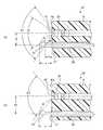
도1은 본 발명에 관한 내시경 시스템에 이용하는 내시경의 삽입부에 마련되는 관찰창과 처치구 채널 개구의 관계를 설명하는 설명도이다.BRIEF DESCRIPTION OF THE DRAWINGS It is explanatory drawing explaining the relationship between the observation window and the treatment instrument channel opening provided in the insertion part of an endoscope used for the endoscope system which concerns on this invention.
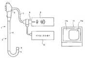
도2는 본 발명에 관한 내시경 시스템에 이용하는 내시경 장치의 개략 구성을 도시하는 블록도이다.2 is a block diagram showing a schematic configuration of an endoscope apparatus used in the endoscope system according to the present invention.
도3은 본 발명에 관한 내시경 시스템에 이용하는 내시경의 삽입부에 마련되는 선단부의 구성을 도시하는 정면도이다.Fig. 3 is a front view showing the configuration of the tip portion provided in the insertion portion of the endoscope used in the endoscope system according to the present invention.
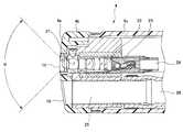
도4는 본 발명에 관한 내시경 시스템에 이용하는 내시경의 삽입부에 마련되는 선단부의 구성을 도시하는 단면도이다.4 is a cross-sectional view showing the configuration of a tip portion provided in an insertion portion of an endoscope used in the endoscope system according to the present invention.
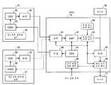
도5는 본 발명에 관한 내시경 시스템에 이용하는 내시경 장치의 구성을 도시하는 블록도이다.Fig. 5 is a block diagram showing the configuration of an endoscope apparatus used in the endoscope system according to the present invention.
<부호의 설명><Description of the code>
1 : 내시경1: endoscope
2 : 삽입부2: insertion part
3 : 조작부3: control panel
4 : 선단부4: Tip
15 : 관찰창15: observation window
17 : 처치구 채널 개구17: treatment instrument channel opening
25 : 처치구 채널25: First Aid Channel
31 : 제1 전자 내시경31: first electronic endoscope
32 : 제2 전자 내시경32: second electronic endoscope
33 : 제1 대물 광학계33: first objective optical system
37 : 제2 대물 광학계37: second objective optical system
이하, 본 발명의 내시경 시스템의 실시 형태에 대해, 도1 내지 도5를 이용하여 설명한다. 도1은 본 발명에 관한 내시경 시스템에 이용하는 내시경의 삽입부에 마련되는 관찰창과 처치구 채널 개구의 관계를 설명하는 설명도, 도2는 본 발명에 관한 내시경 시스템에 이용하는 내시경 장치의 개략 구성을 도시하는 블록도, 도3은 본 발명에 관한 내시경 시스템에 이용하는 내시경의 삽입부에 마련되는 선단부의 구성을 도시하는 정면도, 도4는 본 발명에 관한 내시경 시스템에 이용하는 내시경의 삽입부에 마련되는 선단부의 구성을 도시하는 단면도, 도5는 본 발명에 관한 내시경 시스템에 이용하는 내시경 장치의 구성을 도시하는 블록도이다.EMBODIMENT OF THE INVENTION Hereinafter, embodiment of the endoscope system of this invention is described using FIGS. BRIEF DESCRIPTION OF THE DRAWINGS Explanatory drawing explaining the relationship between the observation window provided in the insertion part of an endoscope used for the endoscope system which concerns on this invention, and a treatment instrument channel opening, and FIG. 2 is a schematic structure of the endoscope apparatus used for the endoscope system which concerns on this invention. Fig. 3 is a front view showing the configuration of the tip portion provided in the insertion portion of the endoscope used in the endoscope system according to the present invention. Fig. 4 is the tip portion provided in the insertion portion of the endoscope used in the endoscope system according to the present invention. Fig. 5 is a block diagram showing the configuration of an endoscope apparatus used in the endoscope system according to the present invention.
최초에, 본 발명에 관한 내시경 시스템에 이용하는 내시경 장치의 개략 구성에 대해 도2를 이용하여 설명한다. 내시경 장치는 내시경(1), 광원 장치(9), 비디오 프로세서(10), 모니터(11)로 이루어진다. 내시경(1)은 선단부(4), 만곡부(5), 가요부(6)로 이루어지는 삽입부(2)와, 이 삽입부(2)의 기단부에 연속 설치된 조작부(3)와, 이 조작부(3)로부터 연장된 유니버설 코드(7)와, 이 유니버설 코드(7)의 선단부에 마련된 내시경 커넥터(8)로 구성되어 있다.First, the schematic structure of the endoscope apparatus used for the endoscope system which concerns on this invention is demonstrated using FIG. The endoscope device consists of an
이 내시경(1)의 선단부(4)는 도시되어 있지 않지만, 조명창, 관찰창, 처치구 채널 개구, 송수 송기 개구 등이 설치되어 있다. 이 선단부(4)의 관찰창에는 관찰 부위로부터의 반사광을 도입하는 대물 광학계가 마련되고, 그 대물 광학계의 결상 위치에 고체 촬상 소자가 설치되어 있다. 이 선단부(4)에 연속 설치된 만곡부(5)는 복수의 만곡구가 배치되고, 조작부(3)에 설치되어 있는 만곡 조작 입력 수단의 일 예로서의 만곡 조작 노브로부터 연장되어 있는 만곡 와이어에 의해 상하 좌우에 만곡한다. 이 만곡부(5)에 연속 설치되어 있는 가요부(6)는 가요성 부재에 의해 길게 형성되어 있다.Although not shown, the
상기 선단부(4), 만곡부(5) 및 가요부(6)에는 라이트 가이드, 신호 케이블, 처치구 채널, 송수 송기 채널이 설치되어 있다. 상기 라이트 가이드의 선단부는, 상기 선단부(4)의 조명창에 배치되어 있다. 상기 신호 케이블의 선단부는 관찰창에 마련된 고체 촬상 소자에 접속되어 있다. 상기 처치구 채널의 선단부는 상기 선단부(4)의 처치구 채널 개구에 배치되어 있다. 상기 송수 송기 채널의 선단부는 상기 선단부(4)의 송수 송기 개구에 배치되어 있다.The
상기 라이트 가이드의 기단부는 상기 조작부(3)로부터 유니버설 코드(7), 내시경 커넥터(8)를 통해, 상기 광원 장치(9)에 접속된다. 상기 신호 케이블의 기단부는 상기 조작부(3)로부터 유니버설 코드(7)와 내시경 커넥터(8)를 통해, 비디오 프로세서(10)에 접속되어 있다. 상기 처치구 채널의 기단부는 상기 조작부(3)에 마련된 처치구 삽입 구멍에 접속되어 있다. 상기 송수 송기 채널의 기단부는 상기 조작부(3)에 마련된 송수 송기 채널 부재에 접속되고, 조작부(3)에 마련된 송수 송기 스위치에 의해 송수 송기된다.The base end of the light guide is connected to the
상기 광원 장치(9)는 조명 램프 램프와 이 조명 램프의 점등 제어 회로를 갖 고 있고, 내시경 커넥터(8)의 라이트 가이드의 기단부에 조명광을 투사한다. 상기 비디오 프로세서(10)는 상기 선단부(4)에 마련된 고체 촬상 소자를 구동시키는 동시에, 고체 촬상 소자에 의해 얻어진 관찰 부위의 촬상 신호를 도입하고, 그 촬상 신호에 대해 소정의 신호 처리를 행하여 영상 신호를 생성한다. 상기 모니터(11)는 상기 비디오 프로세서(10)에 있어서 생성된 영상 신호를 기초로 상기 고체 촬상 소자에 의해 촬상된 관찰 부위의 영상(이하, 관찰 영상이라 칭함)을 내시경 화상 표시 영역(11a)에 표시한다. 또, 이 모니터(11)에는 상기 관찰 영상 이외에, 예를 들어 환자의 성명, 연령, 성별, 내시경 관찰 일시 등의 정보도 동시에 환자 정보 표시 영역(11b)을 표시한다.The
이러한 내시경 장치의 삽입부(2)의 선단부(4)의 구성에 대해, 도3과 도4를 이용하여 설명한다. 또, 도3은 상기 선단부(4)의 선단부면을 정면에서 본 정면도이며, 도4는 도3의 도면 중 절단선 X-X에 의해 선단부(4)를 축 방향으로 절단한 단면도이다.The structure of the
상기 선단부(4)의 선단부면(4a)에는, 도3에 도시한 바와 같이 관찰창(15), 그 관찰창(15)의 주위에 대략 등간격으로 배치된 복수의 조명창(16a, 16b, 16c), 처치구 채널 개구(17), 상기 관찰창(15)에 대해 송수 송기하는 송수 송기 노즐(18) 및 전방 송수 개구(19)가 설치되어 있다.On the
상기 선단부(4)는 선단부 캡(4b)과 원통 형상의 외장(40c)으로 이루어져 내부의 구성은, 도4에 도시한 바와 같이 상기 선단부 캡(4b)의 선단부면(40a)에 마련된 관찰창(15)에는 시야각(α)의 복수의 광학 렌즈로 이루어지는 대물 광학계(21) 가 배치되어 있다. 이 대물 광학계(21)의 결상 위치에는 고체 촬상 소자(22)가 배치되어 있다. 이 고체 촬상 소자(22)의 후방에는 고체 촬상 소자(22)를 구동 제어하거나, 광전 변환 생성된 촬상 신호를 수신하는 회로 기능을 갖는 회로 기판(23)이 접속되어 있다. 이 회로 기판(23)에는 신호 케이블(24)이 접속되고, 이 신호 케이블(24)의 기단부는 상기 비디오 프로세서(10)에 접속되어 있다.The
상기 선단부 캡(4b)의 선단부면(4a)에 마련된 처치구 채널 개구(17)에는, 대략 원통 형상으로 형성된 처치구 삽입 관통통(25)을 통해, 처치구 채널(26)에 연통되어 있다. 또한, 상기 선단부(4)의 선단부면(4a)에 설치되어 있는 조명창(16a 내지 6c)에는 도시하지 않은 조명 렌즈가 마련되고, 그 조명 렌즈에 라이트 가이드의 선단부가 배치되어 있다. 또한, 상기 송수 송기 노즐(18)과 상기 전방 송수 개구(19)에는 도시되어 있지 않지만, 각각 송수 송기 채널과 전방 송기 채널이 연통되어 있다.The treatment
이러한 구성의 선단부(4)를 갖는 내시경(1)을 이용한, 본 발명에 관한 내시경 시스템에 대해 도5를 이용하여 설명한다. 이 내시경 시스템은, 상기 내시경(1)에 상당하는 제1 전자 내시경(31)과 제2 전자 내시경(32), 상기 비디오 프로세서(이하, VPU라 칭함)(10), 모니터(11)로 이루어지고 있다. 또, 제1과 제2 전자 내시경(31, 32)으로부터 관찰 부위에 투사하는 조명광을 생성하는 광원 장치는 도시하고 있지 않다.The endoscope system according to the present invention using the
상기 제1 전자 내시경(31)은, 일반적인 시야각(120도 내지 150도)(α1)의 복수의 렌즈로 이루어지는 제1 대물 광학계(33), 이 제1 대물 광학계(33)의 결상 위 치에 배치되고, 관찰 부위를 촬상하는 제1 고체 촬상 소자(이하, 제1 CCD라 칭함)(34), 이 제1 CCD(34)에 의해 생성된 촬상 신호의 상관 2중 샘플링 처리를 행하는 CDS 회로(35), 이 CDS 회로(35)에 있어서 처리된 아날로그 촬상 신호를 디지털 촬상 신호로 변환하는 아날로그/디지털 변환 회로(이하, A/D 회로라 칭함)(36)로 이루어지고 있다.The first
상기 제2 전자 내시경(32)은, 상기 제1 전자 내시경(31)의 제1 대물 광학계(33)보다 큰 시야각(151도 이상)(α2)(α1 < α2)의 복수의 렌즈로 이루어지는 제2 대물 광학계(37), 이 제2 대물 광학계(37)의 결상 위치에 배치되고, 관찰 부위를 촬상하는 제2 고체 촬상 소자(이하, 제2 CCD라 칭함)(38), 이 제2 CCD(38)에 의해 생성된 촬상 신호의 상관 2중 샘플링 처리를 행하는 CDS 회로(39), 이 CDS 회로(39)에 있어서 처리된 아날로그 촬상 신호를 디지털 촬상 신호로 변환하는 아날로그/디지털 변환 회로(이하, A/D 회로라 칭함)(40)로 이루어지고 있다.The
상기 VPU(10)는 분리 처리 회로(이하, S/P 회로라 칭함)(41), 디지털 신호 처리 회로(이하, DSP 회로라 칭함)(42), 문자 정보 다중 회로(43), 문자 정보 입력 회로(44), 디지털/아날로그 신호 변환 회로(이하, D/A 회로라 칭함)(45), 화상 표시 신호 회로(46), 기준 신호 발생 회로(이하, SSG라 칭함)(47), 타이밍 신호 발생 회로(이하, T/G 회로라 칭함)(48), 표시 화상 절환 입력 회로(49)로 구성된다.The
상기 S/P 회로(41)는, 상기 제1 전자 내시경(31)의 A/D 회로(36)로부터의 디지털 촬상 신호, 또는 상기 제2 전자 내시경(32)의 A/D 회로(40)로부터의 디지털 촬상 신호의 휘도 신호와 색 신호 등을 분리 처리한다. 상기 DSP(42)는, 상기 S/P 회로(41)에 있어서 분리된 휘도 신호와 색 신호에 대해, 소정의 디지털 신호 처리를 행하는 동시에 화이트 밸런스 및 γ 보정 등의 보정 처리를 행하고, 디지털 내시경 화상 신호를 생성한다.The S /
상기 문자 정보 중첩 회로(43)는, 상기 DSP 회로(42)에 있어서 신호 처리된 디지털 내시경 화상 신호에, 예를 들어 환자의 성명, 연령, 성별, 내시경 관찰 일시 등의 환자 정보를 나타낸 문자 정보 신호를 중첩시킨다. 이 문자 정보 중첩 회로(43)에 있어서, 중첩되는 문자 정보 신호는 상기 문자 정보 입력 회로(44)에 있어서, 도시되어 있지 않은 키보드로부터 시술자에 의해 입력된 상기 환자 정보에 의해 생성된다. 이 문자 정보 중첩 회로(43)에 있어서, 문자 정보가 중첩된 디지털 내시경 화상 신호는 상기 D/A 회로(45)에 있어서, 아날로그 내시경 화상 신호로 변환되어 화상 표시 신호 회로(46)로 출력된다. 또, 상기 문자 정보 중첩 회로(43)에 있어서, 생성된 문자 정보 신호가 중첩된 디지털 내시경 화상 신호는 VPU(13)에 착탈 가능하게 마련한 메모리(30)에 기록한다.The character
상기 화상 표시 신호 회로(46)는, 상기 D/A 회로(45)로부터 공급된 아날로그 내시경 화상 신호를 기초로, 모니터(11)에 관찰 영상과 환자 정보를 표시하기 위한 영상 신호로 변환 생성한다. 이 화상 표시 신호 회로(46)는, 상기 표시 화상 절환 입력 회로(49)로부터의 제어 신호에 의해, 상기 모니터(11)에 표시시키는 관찰 영상과 환자 정보의 표시 위치 및 표시 화상의 크기 등이 변경 설정된다. 상기 표시 화상 절환 입력 회로(49)에는 도시되어 있지 않지만, 시술자가 모니터(11)에 표시시키는 관찰 영상, 환자 정보의 표시 위치, 표시 화상의 크기 등의 표시 절환 입력 지시가 가능하게 되어 있다.The image
상기 SSG 회로(47)는, 상기 S/P 회로(41), DSP 회로(42), 문자 정보 중첩 회로(43), D/A 회로(45), 화상 표시 신호 회로(46)의 구동을 제어하는 기준 신호를 생성 출력한다. 상기 T/G 회로(48)는, 상기 SSG 회로(47)로부터의 기준 신호에 의해, 상기 제1과 제2 전자 내시경(31, 32) 각각의 제1과 제2 CCD(34, 38)의 구동 제어의 타이밍 신호를 생성한다.The
또, 상기 제1 전자 내시경(31)과 제2 전자 내시경(32)은, 상기 VPU(10)에 필요에 따라서 커넥터 등을 이용하여 접속되거나, 혹은 상기 VPU(10)에 커넥터에 의해 항상 접속되고, 도시되어 있지 않은 절환 스위치에 의해 접속 절환이 가능하게 된다.The first
다음에, 상기 제1과 제2 전자 내시경(31, 32) 각각의 제1과 제2 대물 광학계(33, 37)가 각각 배치되는 삽입부(2)의 선단부(4)의 구성에 대해, 도1을 이용하여 설명한다. 또, 이 도1은 선단부(4)에 있어서의 관찰창(15)에 마련되는 제1과 제2 대물 광학계(33, 37)와 처치구 채널 개구(17)의 관계를 모식적으로 나타내고 있다.Next, the structure of the
도1의 (a)는 상기 제1 전자 내시경(31)의 선단부(4)를 도시하고 있다. 이 제1 전자 내시경(31)의 선단부(4)에는 관찰창(15), 처치구 채널 개구(17) 및 도시되어 있지 않은 조명창(16a 내지 16c), 송수 송기 노즐(18), 전방 송수 개구(19)가 마련되어 있다. 이 제1 전자 내시경(31)의 관찰창(15)에는, 상기 시야각(α1)의 상기 제1 대물 광학계(33)가 배치되어 있다. 이 선단부(4)의 관찰창(15)의 중심축 과, 처치구 채널 개구(17)의 중심축과는 선단부면에 있어서 도면 중 t1에서 나타내는 간격의 위치 관계로 되도록 마련되어 있다. 이 시야각(α1)의 제1 대물 광학계(33)를 마련한 관찰창(15)과, 이 관찰창(15)으로부터 거리(t1)의 위치에 마련된 처치구 채널 개구(17)와의 위치 관계로부터, 상기 처치구 채널 개구(17)로부터 관찰 부위 방향으로 삽입 관통시킨 처치구(51)는, 상기 제1 대물 광학계(33)의 시야각(α1)의 범위로 돌출시키기 위해서는, 도면 중의 돌출량(1)을 넘어서 돌출시킬 필요가 있다. 이 시야각(α1) 내에 돌출된 처치구(51)는 관찰창(15)으로부터 관찰할 수 있어, 관찰 부위와 처치구(51)의 위치 관계를 파악할 수 있다.FIG. 1A shows the
다음에, 이 관찰창(15)과 처치구 채널 개구(17)가 동일한 거리(t1)만큼 떨어진 위치 관계에 있고, 선단부(4)의 관찰창(15)에 상기 제1 대물 광학계(33)의 시야각(α1)보다 광각의 시야각(α2)을 갖는 제2 대물 광학계(37)를 장착하여 제2 전자 내시경(32)으로 한 경우, 상기 처치구 채널 개구(17)로부터 돌출시킨 처치구(51)는 상기 돌출량(l)보다 아주 적은 도면 중의 돌출량[1'(l > l')]에 의해 시야각(α2)의 범위에 인입하게 된다.Next, the
이와 같이, 제2 대물 광학계(37)의 광각의 시야각(α2)의 범위에는, 약간의 돌출량(l')에 의해 상기 처치구(51)가 인입한다. 이 시야각(α2)에 들어간 처치구(51)의 돌출량(l')은 관찰 부위와의 위치 관계로부터 보면 충분한 돌출량은 아니다.In this manner, the
그래서, 도1의 (b)에 도시한 바와 같이 상기 제2 전자 내시경(32)의 선단부(4')에 있어서, 관찰창(15')에 상기 시야각(α2)의 상기 제2 대물 광학계(37)를 배치하고, 처치구 채널 개구(17')의 중심축을 이 선단부(4')의 관찰창(15')의 중심축으로부터 도면 중[t2(t1 < t2)]에서 나타내는 위치에 마련한다. 이 시야각(α2)의 제2 대물 광학계(37)를 마련한 관찰창(15')과, 이 관찰창(15')으로부터 거리(t2)의 위치에 마련된 처치구 채널 개구(17')의 위치 관계로부터, 상기 처치구 채널 개구(17')로부터 관찰 부위 방향으로 삽입 관통시킨 처치구(51)는, 상기 제2 대물 광학계(37)의 시야각(α2)의 범위에 인입하게 하기 위해서는, 도면 중의 돌출량(l)을 넘어서 돌출시킬 필요가 있다. 즉, 이 제2 전자 내시경(32)의 처치구(51)를 돌출량(l) 이상 돌출시킴으로써, 제2 대물 광학계(37)의 광각 시야각(α2)의 범위에 인입하게 할 수 있다.Thus, as shown in Fig. 1B, in the distal end portion 4 'of the
즉, 이 제2 전자 내시경(32)의 처치구(51)를, 도1의 (a)에 도시한 제1 전자 내시경(31)의 처치구(51)와 같은 돌출량(l)의 돌출 조작을 행하면 각각의 관찰 영상 중에 처치구를 확인할 수 있게 된다. 이에 의해, 시술자는 제1과 제2 전자 내시경(31, 32) 각각의 처치구(51)의 돌출 조작의 감각이 대략 같고, 또한 선단부(4, 4')의 선단부면으로부터의 처치구(51)의 돌출량도 거의 같으므로 관찰 부위와 처치구(51)와의 위치 관계도 대략 동등하게 된다.In other words, the
이상 설명한 바와 같이, 삽입부(2)의 선단부(4)에 마련하는 관찰창(15)과 처치구 채널 개구(17)의 위치 관계는 처치구 채널 개구(17)로부터 돌출시키는 처치구(51)의 돌출량이 대략 동등한 상태에 있어서, 상기 관찰창(15)에 마련한 대물 광학계(33, 37)의 시야각에 따라서 설정함으로써, 시술자는 처치구(51)의 조작 감각, 관찰 부위와 처치구와의 위치 관계의 위화감을 해소할 수 있다.As described above, the positional relationship between the
또, 상술한 사상을 응용함으로써, 단일의 전자 내시경에 대해 대물 광학계의 시야각을 기초로 하여, 삽입부의 선단부에 있어서의 대물 광학계와 처치구 채널 개구 사이의 거리를 정하는 것도 유용하다. 구체적으로는, 예를 들어 처치구 채널 개구로부터 돌출한 처치구의 돌출량이 있는 소정의 값이 되었을 때에, 대물 광학계에 의해 취득되는 관찰 화상 상의 소정의 기준 영역에 처치구 선단부의 상이 표시되도록, 대물 광학계와 처치구 채널 개구 사이의 거리를 정하는 것을 예로 들 수 있다.Further, by applying the above-described idea, it is also useful to determine the distance between the objective optical system and the treatment instrument channel opening at the distal end of the insertion section based on the viewing angle of the objective optical system with respect to the single electron endoscope. Specifically, for example, when the predetermined value with the protrusion amount of the treatment tool protruding from the treatment instrument channel opening is reached, the objective optical system is displayed so that the image of the treatment instrument tip is displayed in the predetermined reference region on the observation image acquired by the objective optical system. An example is the determination of the distance between and the treatment instrument channel opening.
상술한 바와 같이, 삽입부의 직경이나 대물 광학계의 사이즈 등에 의해 대물 광학계와 처치구 채널 개구 사이의 거리를 정하고 있던 종래의 전자 내시경에서는 대물 광학계의 시야가 다른 경우에는, 관찰 화상 상에서 동일한 위치에 처치구가 표시된 경우라도 처치구의 돌출량이 다른 것이 되어, 시술자에 의한 조작에 지장을 초래할 우려가 있었다. 이러한 문제점을 해소하는 관점으로부터, 미리 정한 처치구의 돌출량인 소정의 기준치만큼 처치구가 돌출되었을 때에, 이러한 처치구 선단부의 상이 관찰 화상 상의 소정의 기준 영역 상에 표시되도록 대물 광학계와 처치구 채널 개구 사이의 거리를 정한 전자 내시경을 실현하는 것이 유효하다. 이러한 조건을 충족시키는 거리는, 상술한 바와 같이 대물 광학계의 시야각에 따라서 정해지게 되고, 예를 들어 도1의 (a)에 도시한 예로서는 대물 광학계의 시야각(α1)을 기초로 하여 대물 광학계와 처치구 채널 개구 사이의 거리를 t1로 하고, 도1의 (b)에 도시한 예로서는 시야각(α2)을 기초로 하여 대물 광학계와 처치구 채널 개구 사이의 거리를 t2로 정하는 것이 가능해진다. 이와 같이, 시야각을 기초로 하여 대물 광학계와 처치구 채널 개구 사이의 거리를 정한 전자 내시경을 이용함으로써 다른 시야각의 전자 내시경을 사용한 경우라도, 시술자는 관찰 화상을 참조함으로써 처치구가 어느 정도 돌출되는지를 용이하게 파악하는 것이 가능하고, 전자 내시경의 조작성이 현저히 향상하게 된다.As described above, in the conventional electron endoscope in which the distance between the objective optical system and the treatment instrument channel opening is determined by the diameter of the insertion portion, the size of the objective optical system, or the like, when the field of view of the objective optical system is different, the treatment instrument is positioned at the same position on the observation image. Even if is displayed, the protruding amount of the treatment instrument was different, and there was a risk of causing trouble by the operator. From the viewpoint of eliminating this problem, when the treatment tool protrudes by a predetermined reference value which is a predetermined amount of protrusion of the treatment tool, the objective optical system and the treatment instrument channel opening are displayed so that the image of the treatment instrument tip is displayed on the predetermined reference region on the observation image. It is effective to realize an electronic endoscope with a distance between them. The distance that satisfies these conditions is determined according to the viewing angle of the objective optical system as described above. For example, the objective optical system and the treatment instrument are based on the viewing angle α1 of the objective optical system as shown in FIG. The distance between the channel openings is t1, and in the example shown in Fig. 1B, the distance between the objective optical system and the treatment instrument channel openings can be determined as t2 based on the viewing angle α2. In this way, even when an electron endoscope having a different viewing angle is used by using an electron endoscope that determines the distance between the objective optical system and the treatment instrument channel opening based on the viewing angle, the operator refers to the observation image to determine how much the treatment instrument protrudes. It can be grasped easily, and the operability of an electronic endoscope is remarkably improved.
또, 관찰 화상 상에 있어서의 기준 영역은 임의의 영역으로서 좋지만, 예를 들어 도1의 예에 도시한 바와 같이 관찰 화상의 주연부를 기준 영역으로 하는 것이 바람직하다. 이와 같이 기준 영역을 설정해 둠으로써, 시술자는 처치구를 서서히 돌출시킨 경우에 관찰 화상 상에 처치구 선단부의 상이 표시된 순간에 처치구의 돌출량이 소정의 기준치에 도달한 것으로 용이하게 인식할 수 있다는 이점을 갖는다.In addition, although the reference area on an observation image is good as arbitrary areas, it is preferable to make the peripheral part of an observation image a reference area, for example as shown in the example of FIG. By setting the reference region in this way, the operator can easily recognize that the protrusion amount of the treatment instrument has reached a predetermined reference value when the image of the treatment instrument tip is displayed on the observation image when the treatment instrument is gradually projected. Have
또한, 대물 광학계의 시야각을 기초로 하여 대물 광학계와 처치구 채널 개구 사이의 거리를 정한 전자 내시경의 예로서, 처치구 채널 개구로부터 돌출한 처치구 중 시야각을 기초로 하여 정해지는 대물 광학계의 시야 내에 존재하는 부분이 대물 광학계에 대해 근점보다 원점에 위치하도록 대물 광학계와 처치구 채널 개구 사이의 거리를 정하는 것도 바람직하다. 근점이라 함은, 광학계에 의해 상을 맺는 것이 가능한 최단 거리의 점을 말하며, 대물 광학계의 시야 내에서 처치구가 대물 광학계에 대해 근점보다 원점에 위치하도록 대물 광학계와 처치구 채널 개구 사이의 거리를 정함으로써, 관찰 화상에 나타낸 처치구의 상이 항상 선명한 것이 되어, 시술자는 처치구가 관찰 화상 상에 표시되어 있는 것을 용이하게 인식하는 것이 가능해진다.Moreover, as an example of the electronic endoscope which determined the distance between the objective optical system and the treatment instrument channel opening based on the viewing angle of the objective optical system, within the field of view of the objective optical system determined based on the viewing angle among the treatment instruments protruding from the treatment instrument channel opening. It is also desirable to determine the distance between the objective optics and the treatment instrument channel openings such that the portion present is at the origin rather than the near point relative to the objective optics. The near point refers to the point of the shortest distance that an image can be imaged by the optical system, and the distance between the objective optical system and the treatment channel channel opening is positioned within the field of view of the objective optical system so that the treatment instrument is positioned at the origin rather than the near point with respect to the objective optical system. By determining, the image of the treatment instrument shown in the observation image is always clear, and the operator can easily recognize that the treatment instrument is displayed on the observation image.
이러한 거리가 정하는 방법의 일 예에 대해, 도1을 참조하면서 설명한다. 또, 이하의 설명에서는 간단히 하기 위해 제1 대물 광학계(33) 및 제2 대물 광학계(37) 중 어떠한 것에 대해서도 근점은 대물 광학계로부터의 거리가 d0이 되는 영역에 존재하는 것으로 하고, 후술하는 d1, d2에 대해 d1 > d0 > d2의 관계가 성립하는 것으로 한다.An example of how such a distance is determined will be described with reference to FIG. In addition, in the following description, for the sake of simplicity, in any of the 1st objective
도1의 (a)에서, 제1 대물 광학계(33)의 시야각이 α1인 경우에는, 처치구(51) 중 제1 대물 광학계(33)의 시야 내에 존재하는 부분과 제1 대물 광학계(33)[도1의 (a)인 경우에는, 정확하게는 제1 대물 광학계(33)를 형성하는 관찰창(15)] 사이의 거리(d)의 최소치는 d1(> d0)이 되고, 처치구(51)는 시야각 내에서 제1 대물 광학계(33)에 대해 근점보다 원점에 위치하게 된다. 그로 인해 시야각(α1)의 제1 대물 광학계(33)를 구비한 제1 전자 내시경(31)에서는 관찰 화상 상에 표시되는 처치구(51)의 상은 항상 선명한 것이 되어, 시술자에게 불쾌감을 주는 등의 문제점을 발생시키는 일은 없다.In FIG. 1A, when the viewing angle of the first objective
한편, 도1의 (a)에 있어서 시야각(α2)인 경우에는 사정이 다른 것이 된다. 제1 대물 광학계(33)가 시야각(α2)을 갖는 경우에는, 도1의 (a)에도 도시한 바와 같이 처치구(51) 중 시야각(α2)에 의해 정해지는 제1 대물 광학계(33)의 시야 내에 존재하는 부분과 제1 대물 광학계(33) 사이의 거리(d)의 최소치는 d2가 되고, 시야각 내에 있어서 제1 대물 광학계(33)로부터의 거리가 근점까지의 거리(d0)보다 작은 값이 되는 경우가 생길 수 있게 된다. 그로 인해, 넓은 시야각(α2)인 경우에는 관찰 화상 상에 있어서의 처치구(51)의 상은 선명하지 않게 되는 경우가 있어, 이러한 경우에는 시술자에게 불쾌감을 주는 등의 문제점이 발생하게 된다.On the other hand, in the case of the viewing angle α2 in Fig. 1A, the circumstances are different. When the first objective
시야각(α1,α2)에 있어서의 2가지의 사례에 비추어 보면, 제1 대물 광학계(33)와 처치구(51) 사이의 거리(d)의 최소치가 d0 이상의 값이 되는 것이 문제점을 회피하기 위해 필요하다는 것이 명백하다. 그리고, 도1의 (a)에 도시한 바와 같이 거리(d)의 최소치는 제1 대물 광학계(33)의 시야 한계와 처치구(51)가 교차하는 영역과 제1 대물 광학계(33) 사이의 거리에 의해 정해지게 된다. 따라서, 시야각이 확대된 경우에는, 이러한 교차 영역과 제1 대물 광학계(33) 사이의 거리가 d0 이상의 값이 되도록 처치구 채널(26)을 형성하는 것이 바람직하고, 보다 구체적으로는 거리가 d0 이상의 값이 되도록 처치구 채널 개구(17)와 제1 대물 광학계(33) 사이의 거리를 정하는 것이 바람직하다. 이러한 조건을 충족시키도록 처치구 채널 개구(17)의 위치를 설정함으로써, 예를 들어 도1의 (b)에 도시한 바와 같이 시야각(α2)인 경우에도 거리(d)의 최소치를 d1(> d2)로 하는 것이 가능해지고, 관찰 화상 상에 의해 처치구(51)의 상을 선명하게 표시하는 것이 가능하다. 또, 이러한 구성은 150°이상의 시야각을 갖는 광각의 대물 광학계를 구비한 전자 내시경에 적용하는 것이 바람직하다. 시야가 광각이 되는 경우에 특히 관찰 화상 상에 있어서의 처치구의 상이 선명하지 않게 될 가능성이 높아지기 때문이다.In view of the two cases in the viewing angles α1 and α2, in order to avoid the problem that the minimum value of the distance d between the first objective
그런데, 상기 제1과 제2 전자 내시경(31, 32)의 제1 CCD(34)와 제2 CCD(38)의 화소수 및 어스펙트비가 동일하다고 하면, 상기 시야각(α1)의 제1 대물 광학계(33)와, 이 제1 대물 광학계(33)의 시야각(α1)보다 넓은 시야각(α2)을 갖는 제2 대물 광학계(37)의 각각에 따라서 제1과 제2 CCD(34, 38)에 결상되는 관찰 부위상의 범위는 서로 다르다.By the way, if the number of pixels and the aspect ratio of the
즉, 제1 전자 내시경(31)에 의해 촬상하여, 모니터(11)의 내시경 화상 표시 영역(11a)에 표시되는 관찰 부위의 범위에 비해, 제2 전자 내시경(32)에 의해 촬상하여, 모니터(11)의 동일한 내시경 화상 표시 영역(11a)에 표시되는 관찰 부위의 범위는 넓어진다. 그러나, 이 제2 전자 내시경(32)에 의해 촬상되어 모니터(11)에 표시되어 있는 넓은 범위의 관찰 부위 중 개개의 관찰 부위는, 상기 제1 전자 내시경(31)에 의해 촬상되어 모니터(11)에 표시되어 있는 관찰 부위 중 개개의 관찰 부위에 비교하여 작은 형상으로서 표시된다. 또한, 넓은 관찰 부위 중 개개의 관찰 부위의 화상수가 적기 때문에, 선명하지 않은 화상으로서 표시될 가능성이 있다.That is, it captures with the 1st
그래서, 상기 광각의 시야각(α2)을 갖는 제2 대물 광학계(37)를 갖는 제2 전자 내시경(32)의 제2 CCD(38)에는, 상기 제1 전자 내시경(31)의 제1 CCD(34)보다 화소수가 많고, 고화소 CCD를 이용한다.Therefore, in the
이 제2 전자 내시경(32)의 제2 CCD(38)를 고화소화함으로써, 시야각(α2)을 갖는 제2 대물 광학계(37)를 기초로 하여, 촬상된 촬상 신호로부터 모니터(11)에 표시되는 관찰 부위의 영상(관찰 영상)의 화소는, 상기 제1 전자 내시경(31)에 비해 많기 때문에, 제2 전자 내시경(32)의 관찰 부위의 영상 전체와, 그 관찰 부위의 영상 중 개개의 관찰 부위의 해상도의 향상이 가능해진다. 또한, 그 제2 전자 내시경(32)의 고화소의 제2 CCD(38)에 의해 촬상 생성된 고화소의 관찰 부위의 화상으로부터 전자적으로 줌 처리를 행하고, 모니터(11)에 줌 관찰 부위의 화상으로서 표시해도 고화소이기 때문에 해상도의 열화를 억제할 수 있다.By high pixelizing the
이상 설명한 바와 같이, 시야각이 광각의 대물 광학계를 갖는 전자 내시경은 고화소의 CCD를 이용함으로써, 넓은 촬영 범위의 개개의 관찰 부위와, 전자적 줌 처리되었을 때의 줌 표시 관찰 부위의 화질 열화를 억제할 수 있다.As described above, the electronic endoscope having a wide-angle objective optical system can suppress deterioration in image quality of individual observation sites in a wide shooting range and zoom display observation sites when subjected to electronic zoom by using a high-pixel CCD. have.
[부기][bookkeeping]
이상 상세하게 서술한 본 발명의 실시 형태에 따르면, 이하 같은 구성을 얻을 수 있다.According to embodiment of this invention described in detail above, the following structures can be obtained.
(부기 1)(Book 1)
내시경을 이용하여 관찰 부위를 관찰 및 처치하는 내시경 시스템에 있어서,In an endoscope system that observes and treats an observation site using an endoscope,
삽입부의 선단부에 있어서의 관찰창에 소정의 시야각을 갖는 제1 대물 광학계가 마련되고, 이 관찰창으로부터 소정의 간격의 위치에 상기 처치구 채널 개구가 마련된 제1 내시경과,A first objective optical system having a predetermined viewing angle at the observation window at the distal end of the insertion section, the first endoscope provided with the treatment instrument channel opening at a predetermined interval from the observation window;
삽입부의 선단부에 있어서의 관찰창에 상기 제1 대물 광학계의 시야각보다 넓은 시야각을 갖는 제2 대물 광학계가 마련되고, 이 제2 대물 광학계가 마련된 관찰창으로부터, 상기 제1 내시경의 관찰창과 처치구 채널 개구와의 간격의 위치보다 넓은 간격의 위치에 처치구 채널 개구가 마련된 제2 내시경을 구비한 것을 특징으로 하는 내시경 시스템.A second objective optical system having a viewing angle wider than the viewing angle of the first objective optical system is provided in the observation window at the distal end of the insertion section. From the observation window provided with the second objective optical system, the observation window and the treatment instrument channel of the first endoscope are provided. An endoscope system, comprising a second endoscope provided with a treatment instrument channel opening at a position spaced apart from the position with respect to the opening.
(부기 2)(Supplementary Note 2)
피검체 내에 삽입하는 삽입부의 선단부에 있어서의 관찰창에 소정의 시야각을 갖는 제1 대물 광학계가 마련된 제1 내시경과, 피검체 내에 삽입하는 삽입부의 선단부에 있어서의 관찰창에 상기 제1 대물 광학계의 시야각과 다른 시야각을 갖는 제2 대물 광학계가 마련된 제2 내시경으로 이루어지고, 상기 제1과 제2 내시경 각 각의 처치구 채널 개구로부터 돌출되는 처치구의 돌출량이 대략 동등한 상태에 있어서,The first endoscope provided with the first objective optical system having a predetermined viewing angle in the observation window at the distal end of the insertion part inserted into the subject, and the observation window at the distal end of the insertion part inserted into the subject. In the state which consists of the 2nd endoscope provided with the 2nd objective optical system which has a viewing angle different from a viewing angle, and the protrusion of the treatment instrument which protrudes from the treatment instrument channel opening of each of said 1st and 2nd endoscopes,
상기 제1 대물 광학계와 제2 대물 광학계 각각의 시야각 내에 각각의 처치구가 인입하도록, 상기 제1과 제2 내시경 각각의 처치구 채널 개구와 관찰창의 간격의 위치를 설정한 것을 특징으로 하는 내시경 시스템.Endoscope system, characterized in that the position of the interval between the treatment instrument channel opening and the observation window of each of the first and the second endoscope so that each treatment instrument is introduced into the viewing angle of each of the first objective optical system and the second objective optical system .
(부기 3)(Supplementary Note 3)
상기 제2 내시경의 제2 대물 광학계의 시야각은, 상기 제1 내시경의 제1 대물 광학계의 시야각보다 넓고, 상기 제2 내시경의 관찰창과 처치구 채널 개구의 간격은, 상기 제1 내시경의 관찰창과 처치구 채널 개구의 간격보다 넓은 것을 특징으로 하는 부기 2에 기재된 내시경 시스템.The viewing angle of the second objective optical system of the second endoscope is wider than the viewing angle of the first objective optical system of the first endoscope, and the interval between the observation window of the second endoscope and the opening of the treatment instrument channel is the observation window of the first endoscope and the treatment. An endoscope system according to
(부기 4)(Appendix 4)
상기 제1과 제2 대물 광학계 각각의 결상 위치에 고체 촬상 소자가 마련된 제1과 제2 내시경에 있어서, 상기 제2 대물 광학계의 결상 위치에는 상기 제1 대물 광학계의 결상 위치에 마련된 고체 촬상 소자보다 고화소의 고체 촬상 소자를 이용한 것을 특징으로 하는 부기 1 내지 부기 3 중 어느 하나에 기재된 내시경 시스템.In the first and second endoscopes provided with the solid-state imaging device at the imaging position of each of the first and second objective optical systems, the imaging position of the second objective optical system is more than the solid-state imaging device provided at the imaging position of the first objective optical system. An endoscope system according to any one of
(부기 5)(Appendix 5)
삽입부의 선단부에 적어도 소정의 시야각을 갖는 대물 광학계와 처치구를 삽입 관통하는 처치구 채널의 개구가 마련된 내시경이며,An endoscope provided with an objective optical system having at least a predetermined viewing angle and an opening of a treatment instrument channel through which the treatment instrument is inserted at the distal end of the insertion portion;
상기 선단부에 있어서의 상기 처치구 채널의 개구와 상기 대물 광학계의 간격을, 상기 내시경보다 시야각이 좁은 대물 광학계를 갖는 내시경의 선단부에 있어 서의 처치구 채널과 대물 광학계의 간격보다 크게 설정한 것을 특징으로 하는 내시경.The interval between the opening of the treatment instrument channel and the objective optical system in the tip portion is set larger than the interval between the treatment instrument channel and the objective optical system in the distal end portion of the endoscope having an objective optical system having a narrower viewing angle than the endoscope. Endoscope.
(부기 6)(Supplementary Note 6)
상기 내시경은, 이 내시경보다 시야각이 좁은 대물 광학계를 갖는 내시경과 동일한 신호 처리 장치에 접속 가능한 것을 특징으로 하는 부기 5에 기재된 내시경.The endoscope can be connected to the same signal processing apparatus as an endoscope having an objective optical system with a narrower viewing angle than the endoscope.
(부기 7)(Appendix 7)
삽입부의 선단부에 적어도 소정의 시야각을 갖는 대물 광학계가 마련된 내시경이며, 이 내시경보다 시야각이 좁은 대물 광학계에 이용한 고체 촬상 소자보다 화소가 많은 고체 촬상 소자를 이용한 것을 특징으로 하는 내시경.An endoscope provided with an objective optical system having at least a predetermined viewing angle at the distal end of the insertion section, wherein the solid-state imaging device uses more solid-state imaging devices than the solid-state imaging device used in the objective optical system having a narrower viewing angle than the endoscope.
이상과 같이, 본 발명에 관한 내시경은, 예를 들어 의료 분야에 있어서, 시야각이 넓은 내시경 또는 다른 시야각을 갖는 복수의 내시경을 구비한 내시경 시스템에 적용하는 것이 유용하다.As mentioned above, it is useful to apply the endoscope which concerns on this invention to the endoscope system provided with the some endoscope which has a wide viewing angle, or another viewing angle, for example in the medical field.
Claims (8)
Translated fromKoreanApplications Claiming Priority (2)
| Application Number | Priority Date | Filing Date | Title |
|---|---|---|---|
| JP2003417076AJP2005169009A (en) | 2003-12-15 | 2003-12-15 | Endoscope system and endoscope |
| JPJP-P-2003-00417076 | 2003-12-15 |
Publications (2)
| Publication Number | Publication Date |
|---|---|
| KR20060108713Atrue KR20060108713A (en) | 2006-10-18 |
| KR100796415B1 KR100796415B1 (en) | 2008-01-21 |
Family
ID=34675181
Family Applications (1)
| Application Number | Title | Priority Date | Filing Date |
|---|---|---|---|
| KR1020067011677AExpired - Fee RelatedKR100796415B1 (en) | 2003-12-15 | 2004-12-15 | Endoscopy System and Endoscope |
Country Status (8)
| Country | Link |
|---|---|
| US (1) | US7914444B2 (en) |
| EP (1) | EP1695653A4 (en) |
| JP (1) | JP2005169009A (en) |
| KR (1) | KR100796415B1 (en) |
| CN (1) | CN100469303C (en) |
| AU (1) | AU2004296136B2 (en) |
| CA (1) | CA2549567C (en) |
| WO (1) | WO2005055817A1 (en) |
Cited By (2)
| Publication number | Priority date | Publication date | Assignee | Title |
|---|---|---|---|---|
| KR20160006857A (en) | 2014-07-09 | 2016-01-20 | 서울대학교산학협력단 | medical imaging system using endoscope and method for controlling the same |
| WO2023013860A1 (en) | 2021-08-06 | 2023-02-09 | 주식회사 메타플바이오 | Multispectrum endoscope and endoscope system comprising same |
Families Citing this family (33)
| Publication number | Priority date | Publication date | Assignee | Title |
|---|---|---|---|---|
| JP4554267B2 (en) | 2004-04-27 | 2010-09-29 | オリンパス株式会社 | Endoscope and endoscope system |
| RU2006144442A (en) | 2004-05-14 | 2008-06-20 | Олимпус Медикал Системз Корп. (Jp) | ELECTRONIC ENDOSCOPE |
| US8137265B2 (en)* | 2005-03-18 | 2012-03-20 | Olympus Medical Systems Corp. | Endoscope, endoscope system, and switching circuit member for endoscope |
| WO2011092681A1 (en) | 2010-01-26 | 2011-08-04 | Sialo-Lite Ltd. | Dental implants, devices and methods associated with dental implantation procedures |
| US20100047733A1 (en)* | 2005-07-12 | 2010-02-25 | Sialo-Lite Ltd. | Device, system and method for procedures associated with the intra-oral cavity |
| IL169641A0 (en) | 2005-07-12 | 2009-02-11 | Sialo Lite Ltd | Device and system for root canal treatment |
| US8840566B2 (en)* | 2007-04-02 | 2014-09-23 | University Of Washington | Catheter with imaging capability acts as guidewire for cannula tools |
| JP2009056105A (en)* | 2007-08-31 | 2009-03-19 | Olympus Medical Systems Corp | Endoscope with variable focal length |
| US8360964B2 (en)* | 2007-12-10 | 2013-01-29 | Stryker Corporation | Wide angle HDTV endoscope |
| JP5291955B2 (en)* | 2008-03-10 | 2013-09-18 | 富士フイルム株式会社 | Endoscopy system |
| US8747297B2 (en)* | 2009-03-02 | 2014-06-10 | Olympus Corporation | Endoscopic heart surgery method |
| JP5415925B2 (en)* | 2009-03-02 | 2014-02-12 | オリンパス株式会社 | Endoscope |
| US11864734B2 (en) | 2009-06-18 | 2024-01-09 | Endochoice, Inc. | Multi-camera endoscope |
| US9101268B2 (en)* | 2009-06-18 | 2015-08-11 | Endochoice Innovation Center Ltd. | Multi-camera endoscope |
| WO2011037046A1 (en)* | 2009-09-22 | 2011-03-31 | オリンパス株式会社 | Device for injecting therapeutic solution |
| JP5567840B2 (en)* | 2009-09-22 | 2014-08-06 | オリンパス株式会社 | Cell injection device |
| EP2481377A4 (en)* | 2009-09-22 | 2017-12-20 | Olympus Corporation | Space-securing device |
| CN102411201A (en)* | 2010-09-25 | 2012-04-11 | 医电鼎众股份有限公司 | Endoscope device |
| WO2012153736A1 (en)* | 2011-05-12 | 2012-11-15 | オリンパスメディカルシステムズ株式会社 | Endoscope system |
| JP2012245056A (en)* | 2011-05-25 | 2012-12-13 | Canon Inc | Endoscope |
| US9561022B2 (en) | 2012-02-27 | 2017-02-07 | Covidien Lp | Device and method for optical image correction in metrology systems |
| US9060674B2 (en) | 2012-10-11 | 2015-06-23 | Karl Storz Imaging, Inc. | Auto zoom for video camera |
| US20160367120A1 (en) | 2015-06-19 | 2016-12-22 | Children's Medical Center Corporation | Optically Guided Surgical Devices |
| CA3014320A1 (en) | 2016-02-12 | 2017-08-17 | Children's Medical Center Corporation | Instrument port with integrated imaging system |
| US20200099864A1 (en)* | 2017-01-26 | 2020-03-26 | Sony Olympus Medical Solutions Inc. | Medical observation apparatus and control method |
| GB201706497D0 (en)* | 2017-04-25 | 2017-06-07 | Kwong Tsong Yun | New product |
| US11324555B2 (en) | 2018-03-09 | 2022-05-10 | The Children's Medical Center Corporation | Instrument port including optical bulb secured to port body |
| US11213316B2 (en) | 2018-03-09 | 2022-01-04 | The Children's Medical Center Corporation | Gasket with multi-leaflet valve for surgical port apparatus |
| US11284788B2 (en) | 2018-03-09 | 2022-03-29 | The Children's Medical Center Corporation | Instrument port with fluid flush system |
| US11547276B2 (en) | 2018-03-09 | 2023-01-10 | The Children's Medical Center Corporation | Optical bulb for surgical instrument port |
| CN108803003A (en)* | 2018-08-21 | 2018-11-13 | 武汉功匠内窥镜设备有限公司 | A kind of endoscope lens module |
| WO2021171496A1 (en)* | 2020-02-27 | 2021-09-02 | オリンパス株式会社 | Endoscope, insertion part of endoscope and endoscope manufacturing method |
| DE112020007717T5 (en)* | 2020-10-20 | 2023-08-10 | Japan Lifeline Co., Ltd | MEDICAL DEVICE |
Family Cites Families (20)
| Publication number | Priority date | Publication date | Assignee | Title |
|---|---|---|---|---|
| US3924608A (en)* | 1973-05-23 | 1975-12-09 | Olympus Optical Co | Endoscope |
| US4436087A (en)* | 1977-12-11 | 1984-03-13 | Kabushiki Kaisha Medos Kenkyusho | Bioptic instrument |
| US4588294A (en)* | 1984-06-27 | 1986-05-13 | Warner-Lambert Technologies, Inc. | Searching and measuring endoscope |
| DE3582253D1 (en)* | 1985-12-17 | 1991-04-25 | Warner Lambert Tech | ENDOSCOPE FOR MEASURING AND EXAMINATIONS. |
| JPH04102432A (en) | 1990-08-23 | 1992-04-03 | Olympus Optical Co Ltd | Endoscope |
| JPH08126606A (en)* | 1994-10-31 | 1996-05-21 | Olympus Optical Co Ltd | Endoscopic mechanism |
| US6063095A (en)* | 1996-02-20 | 2000-05-16 | Computer Motion, Inc. | Method and apparatus for performing minimally invasive surgical procedures |
| US6066090A (en)* | 1997-06-19 | 2000-05-23 | Yoon; Inbae | Branched endoscope system |
| US6117071A (en)* | 1997-07-29 | 2000-09-12 | Asahi Kogaku Kogyo Kabushiki Kaisha | Endoscope with movable imaging unit for zooming or focusing |
| US6059719A (en)* | 1997-08-06 | 2000-05-09 | Olympus Optical Co., Ltd. | Endoscope system |
| US6409658B1 (en)* | 1998-12-14 | 2002-06-25 | Fuji Photo Optical Co., Ltd. | Endoscope with objective lens drive mechanism |
| JP2001166223A (en)* | 1999-12-03 | 2001-06-22 | Olympus Optical Co Ltd | Endoscope |
| JP4477280B2 (en)* | 2000-03-16 | 2010-06-09 | メディガス リミテッド | Gastric fistula wall forming device |
| JP3988367B2 (en)* | 2000-08-17 | 2007-10-10 | フジノン株式会社 | Endoscope imaging device |
| JP2003164412A (en)* | 2001-11-30 | 2003-06-10 | Olympus Optical Co Ltd | Control system |
| JP2003204920A (en)* | 2002-01-11 | 2003-07-22 | Olympus Optical Co Ltd | Insertion assisting tool |
| JP4022093B2 (en)* | 2002-04-15 | 2007-12-12 | オリンパス株式会社 | Endoscope |
| US7267647B2 (en)* | 2003-02-10 | 2007-09-11 | Pentax Corporation | Endoscope |
| JP4533695B2 (en)* | 2003-09-23 | 2010-09-01 | オリンパス株式会社 | Treatment endoscope |
| US7658738B2 (en)* | 2004-05-14 | 2010-02-09 | Ethicon Endo-Surgery, Inc. | Medical devices for use with endoscope |
- 2003
- 2003-12-15JPJP2003417076Apatent/JP2005169009A/enactivePending
- 2004
- 2004-12-15WOPCT/JP2004/018739patent/WO2005055817A1/ennot_activeApplication Discontinuation
- 2004-12-15CACA2549567Apatent/CA2549567C/ennot_activeExpired - Fee Related
- 2004-12-15CNCNB2004800374536Apatent/CN100469303C/ennot_activeExpired - Fee Related
- 2004-12-15EPEP04807098Apatent/EP1695653A4/ennot_activeWithdrawn
- 2004-12-15KRKR1020067011677Apatent/KR100796415B1/ennot_activeExpired - Fee Related
- 2004-12-15AUAU2004296136Apatent/AU2004296136B2/ennot_activeCeased
- 2006
- 2006-06-14USUS11/452,812patent/US7914444B2/enactiveActive
Cited By (3)
| Publication number | Priority date | Publication date | Assignee | Title |
|---|---|---|---|---|
| KR20160006857A (en) | 2014-07-09 | 2016-01-20 | 서울대학교산학협력단 | medical imaging system using endoscope and method for controlling the same |
| WO2023013860A1 (en) | 2021-08-06 | 2023-02-09 | 주식회사 메타플바이오 | Multispectrum endoscope and endoscope system comprising same |
| KR20230021865A (en) | 2021-08-06 | 2023-02-14 | 주식회사 메타플바이오 | Multispectral endoscope and endoscope system including thereof |
Also Published As
| Publication number | Publication date |
|---|---|
| AU2004296136A1 (en) | 2005-06-23 |
| CA2549567C (en) | 2011-08-30 |
| AU2004296136A2 (en) | 2005-06-23 |
| AU2004296136B2 (en) | 2008-05-22 |
| CA2549567A1 (en) | 2005-06-23 |
| KR100796415B1 (en) | 2008-01-21 |
| JP2005169009A (en) | 2005-06-30 |
| US20060235273A1 (en) | 2006-10-19 |
| CN100469303C (en) | 2009-03-18 |
| CN1893873A (en) | 2007-01-10 |
| EP1695653A1 (en) | 2006-08-30 |
| EP1695653A4 (en) | 2009-07-08 |
| US7914444B2 (en) | 2011-03-29 |
| WO2005055817A1 (en) | 2005-06-23 |
Similar Documents
| Publication | Publication Date | Title |
|---|---|---|
| KR100796415B1 (en) | Endoscopy System and Endoscope | |
| KR100852310B1 (en) | Endoscope and endoscope system | |
| US8002697B2 (en) | Dual endoscope system with display unit | |
| US20070049795A1 (en) | Endoscope system, endoscope apparatus, and image processing apparatus | |
| KR20050011468A (en) | Flexible dual endoscopy for laproscope | |
| JP5114170B2 (en) | Endoscope system | |
| JP2006136743A (en) | Endoscope system and endoscope apparatus | |
| JPH0713087A (en) | Hard endoscope device | |
| JP2007160123A (en) | Endoscope and endoscope system | |
| JP3714636B2 (en) | Endoscope device | |
| JP4436537B2 (en) | Endoscope | |
| JP3034905B2 (en) | Electronic endoscope | |
| KR100879686B1 (en) | Endoscopy system, endoscope device and image processing device | |
| US20170188798A1 (en) | Endoscope system | |
| JP6407044B2 (en) | Endoscope device | |
| JPH07313450A (en) | Endoscope device | |
| JP2007125277A (en) | Electronic endoscope device | |
| JPH0544007B2 (en) |
Legal Events
| Date | Code | Title | Description |
|---|---|---|---|
| A201 | Request for examination | ||
| P11-X000 | Amendment of application requested | St.27 status event code:A-2-2-P10-P11-nap-X000 | |
| P13-X000 | Application amended | St.27 status event code:A-2-2-P10-P13-nap-X000 | |
| PA0105 | International application | St.27 status event code:A-0-1-A10-A15-nap-PA0105 | |
| PA0201 | Request for examination | St.27 status event code:A-1-2-D10-D11-exm-PA0201 | |
| P11-X000 | Amendment of application requested | St.27 status event code:A-2-2-P10-P11-nap-X000 | |
| P13-X000 | Application amended | St.27 status event code:A-2-2-P10-P13-nap-X000 | |
| PG1501 | Laying open of application | St.27 status event code:A-1-1-Q10-Q12-nap-PG1501 | |
| E902 | Notification of reason for refusal | ||
| PE0902 | Notice of grounds for rejection | St.27 status event code:A-1-2-D10-D21-exm-PE0902 | |
| P11-X000 | Amendment of application requested | St.27 status event code:A-2-2-P10-P11-nap-X000 | |
| P13-X000 | Application amended | St.27 status event code:A-2-2-P10-P13-nap-X000 | |
| E701 | Decision to grant or registration of patent right | ||
| PE0701 | Decision of registration | St.27 status event code:A-1-2-D10-D22-exm-PE0701 | |
| GRNT | Written decision to grant | ||
| PR0701 | Registration of establishment | St.27 status event code:A-2-4-F10-F11-exm-PR0701 | |
| PR1002 | Payment of registration fee | St.27 status event code:A-2-2-U10-U12-oth-PR1002 Fee payment year number:1 | |
| PG1601 | Publication of registration | St.27 status event code:A-4-4-Q10-Q13-nap-PG1601 | |
| PR1001 | Payment of annual fee | St.27 status event code:A-4-4-U10-U11-oth-PR1001 Fee payment year number:4 | |
| PR1001 | Payment of annual fee | St.27 status event code:A-4-4-U10-U11-oth-PR1001 Fee payment year number:5 | |
| FPAY | Annual fee payment | Payment date:20121227 Year of fee payment:6 | |
| PR1001 | Payment of annual fee | St.27 status event code:A-4-4-U10-U11-oth-PR1001 Fee payment year number:6 | |
| FPAY | Annual fee payment | Payment date:20131218 Year of fee payment:7 | |
| PR1001 | Payment of annual fee | St.27 status event code:A-4-4-U10-U11-oth-PR1001 Fee payment year number:7 | |
| FPAY | Annual fee payment | Payment date:20141230 Year of fee payment:8 | |
| PR1001 | Payment of annual fee | St.27 status event code:A-4-4-U10-U11-oth-PR1001 Fee payment year number:8 | |
| LAPS | Lapse due to unpaid annual fee | ||
| PC1903 | Unpaid annual fee | St.27 status event code:A-4-4-U10-U13-oth-PC1903 Not in force date:20160115 Payment event data comment text:Termination Category : DEFAULT_OF_REGISTRATION_FEE | |
| R18-X000 | Changes to party contact information recorded | St.27 status event code:A-5-5-R10-R18-oth-X000 | |
| PC1903 | Unpaid annual fee | St.27 status event code:N-4-6-H10-H13-oth-PC1903 Ip right cessation event data comment text:Termination Category : DEFAULT_OF_REGISTRATION_FEE Not in force date:20160115 | |
| P22-X000 | Classification modified | St.27 status event code:A-4-4-P10-P22-nap-X000 |