KR20060107625A - Dust collection assembly of vacuum cleaner - Google Patents
Dust collection assembly of vacuum cleanerDownload PDFInfo
- Publication number
- KR20060107625A KR20060107625AKR1020050029825AKR20050029825AKR20060107625AKR 20060107625 AKR20060107625 AKR 20060107625AKR 1020050029825 AKR1020050029825 AKR 1020050029825AKR 20050029825 AKR20050029825 AKR 20050029825AKR 20060107625 AKR20060107625 AKR 20060107625A
- Authority
- KR
- South Korea
- Prior art keywords
- dust
- air
- vacuum cleaner
- container
- filter
- Prior art date
- Legal status (The legal status is an assumption and is not a legal conclusion. Google has not performed a legal analysis and makes no representation as to the accuracy of the status listed.)
- Ceased
Links
- 239000000428dustSubstances0.000titleclaimsabstractdescription142
- 238000007789sealingMethods0.000claimsabstractdescription12
- 239000000126substanceSubstances0.000claimsabstractdescription9
- 239000000463materialSubstances0.000claimsdescription11
- 238000001914filtrationMethods0.000abstractdescription5
- 230000008901benefitEffects0.000abstractdescription4
- 230000007246mechanismEffects0.000description10
- 230000006835compressionEffects0.000description9
- 238000007906compressionMethods0.000description9
- 230000008878couplingEffects0.000description6
- 238000010168coupling processMethods0.000description6
- 238000005859coupling reactionMethods0.000description6
- 238000012790confirmationMethods0.000description5
- 238000000034methodMethods0.000description5
- 238000012856packingMethods0.000description4
- 238000004140cleaningMethods0.000description2
- 230000008569processEffects0.000description2
- 238000005452bendingMethods0.000description1
- 230000000903blocking effectEffects0.000description1
- 238000007599dischargingMethods0.000description1
- 230000005611electricityEffects0.000description1
- 239000002657fibrous materialSubstances0.000description1
- 238000012986modificationMethods0.000description1
- 230000004048modificationEffects0.000description1
- 238000005192partitionMethods0.000description1
- 229920000728polyesterPolymers0.000description1
- 229920001296polysiloxanePolymers0.000description1
- 238000000926separation methodMethods0.000description1
- 229910052710siliconInorganic materials0.000description1
- 239000010703siliconSubstances0.000description1
- 229920003002synthetic resinPolymers0.000description1
- 239000000057synthetic resinSubstances0.000description1
- 238000005406washingMethods0.000description1
Images


Classifications
- A—HUMAN NECESSITIES
- A47—FURNITURE; DOMESTIC ARTICLES OR APPLIANCES; COFFEE MILLS; SPICE MILLS; SUCTION CLEANERS IN GENERAL
- A47L—DOMESTIC WASHING OR CLEANING; SUCTION CLEANERS IN GENERAL
- A47L11/00—Machines for cleaning floors, carpets, furniture, walls, or wall coverings
- A47L11/40—Parts or details of machines not provided for in groups A47L11/02 - A47L11/38, or not restricted to one of these groups, e.g. handles, arrangements of switches, skirts, buffers, levers
- A47L11/4011—Regulation of the cleaning machine by electric means; Control systems and remote control systems therefor
- A—HUMAN NECESSITIES
- A47—FURNITURE; DOMESTIC ARTICLES OR APPLIANCES; COFFEE MILLS; SPICE MILLS; SUCTION CLEANERS IN GENERAL
- A47L—DOMESTIC WASHING OR CLEANING; SUCTION CLEANERS IN GENERAL
- A47L11/00—Machines for cleaning floors, carpets, furniture, walls, or wall coverings
- A47L11/40—Parts or details of machines not provided for in groups A47L11/02 - A47L11/38, or not restricted to one of these groups, e.g. handles, arrangements of switches, skirts, buffers, levers
- A47L11/4002—Installations of electric equipment
- A47L11/4008—Arrangements of switches, indicators or the like
- A—HUMAN NECESSITIES
- A47—FURNITURE; DOMESTIC ARTICLES OR APPLIANCES; COFFEE MILLS; SPICE MILLS; SUCTION CLEANERS IN GENERAL
- A47L—DOMESTIC WASHING OR CLEANING; SUCTION CLEANERS IN GENERAL
- A47L11/00—Machines for cleaning floors, carpets, furniture, walls, or wall coverings
- A47L11/40—Parts or details of machines not provided for in groups A47L11/02 - A47L11/38, or not restricted to one of these groups, e.g. handles, arrangements of switches, skirts, buffers, levers
- A47L11/408—Means for supplying cleaning or surface treating agents
- A47L11/4086—Arrangements for steam generation
Landscapes
- Filters For Electric Vacuum Cleaners (AREA)
Abstract
Translated fromKoreanDescription
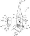
Translated fromKorean도 1은 일반적인 진공청소기의 외관구성을 도시한 사시도.1 is a perspective view showing an appearance configuration of a general vacuum cleaner.
도 2는 본 발명에 의한 진공청소기 집진어셈블리의 바람직한 실시예의 사용상태를 보인 업라이트형 진공청소기의 사시도.Figure 2 is a perspective view of an upright type vacuum cleaner showing a state of use of the preferred embodiment of the vacuum cleaner dust collection assembly according to the present invention.
도 3은 본 발명에 의한 진공청소기 집진어셈블리의 바람직한 실시예가 업라이트형 진공청소기로부터 분리된 상태를 보인 분해사시도.Figure 3 is an exploded perspective view showing a preferred embodiment of the vacuum cleaner dust collection assembly according to the present invention separated from the upright vacuum cleaner.
도 4는 본 발명에 의한 진공청소기 집진어셈블리의 바람직한 실시예의 분해사시도.Figure 4 is an exploded perspective view of a preferred embodiment of the vacuum cleaner dust collection assembly according to the present invention.
도 5는 본 발명에 의한 진공청소기 집진어셈블리의 바람직한 실시예의 내부구성을 보인 단면도.Figure 5 is a cross-sectional view showing the internal configuration of a preferred embodiment of the vacuum cleaner dust collection assembly according to the present invention.
도 6은 본 발명에 의한 진공청소기 집진어셈블리를 구성하는 상면커버의 저면 사시도.Figure 6 is a bottom perspective view of the top cover constituting the vacuum cleaner dust collecting assembly according to the present invention.
* 도면의 주요 부분에 대한 부호의 설명 *Explanation of symbols on the main parts of the drawings
50. 진공청소기60. 흡입노즐체50.
70. 바디72. 집진장착부70.
74. 흡입유로76. 배출유로74. Suction
78. 착탈노브78'. 노브홈78. Release knob 78 '. Knob
100. 집진어셈블리110. 집진통100.
110'. 사이클론통110". 먼지통110 '. Cyclone bin 110 ". Dust bin
112. 흡입가이드120. 실링부재112.
130. 집진손잡이140. 상면커버130. Dust Collector Knob 140. Top Cover
150. 필터조립체152. 필터150.
154. 하단고정부156. 상단고정부154. Upper Fixed
160. 필터고정부재170. 이동부재160.
177. 분리판178. 토출안내관177.
179. 배기구180. 힌지기구179. Vent
190. 체결기구200. 장착수단190.
S. 압축스프링S. Compression Spring
본 발명은 진공청소기에 관한 것으로, 보다 상세하게는 공기중의 이물을 걸러내는 사이클론통과, 필터링 된 이물이 쌓이는 먼지통이 분리되는 진공청소기의 집진어셈블리에 관한 것이다.BACKGROUND OF THE
도 1에는 일반적인 진공청소기의 구성이 도시되어 있다. 도시한 바와 같이, 진공청소기는, 실내의 공기를 흡입하는 흡입수단이 내장된 본체(1)와, 상기 본체(1)에서 발생하는 흡입력에 의하여 바닥면의 공기가 유입되는 흡입노즐(2)을 포함하는 구성을 가진다.1 shows a configuration of a general vacuum cleaner. As shown in the drawing, the vacuum cleaner includes a
한편 상기 본체(1)는, 흡입수단이 수납되어 체결되는 하부몸체(5)와, 상기 하부몸체(5)에 내장된 부품이 외부로 드러나지 않도록 하고, 진공청소기를 제어하는 전장부(도시 생략)가 내장되는 상부몸체(6)로 구성된다.On the other hand, the
또한 상기 본체(1)가 바닥면을 원활하게 이동할 수 있도록 그 몸체의 양측면에 바퀴(8)가 체결되고, 상기 바퀴(8)에는 흡입노즐(2)을 통하여 흡입된 다음 필터링된 공기가 본체(1)로부터 배출되는 토출부(8a)가 형성된다.In addition,
그리고 상기 본체(1)와 흡입노즐(2) 사이에는, 플렉시블한 재질의 것으로 만들어지는 흡입호스(3b)와, 상기 흡입호스(3b)의 단부에 연결되는 조작부(4)와, 상기 조작부(4)와 흡입노즐(2)을 연결하는 연장관(3a) 등이 순차적으로 설치되어 있어서, 본체(1)에서 발생하는 흡입력을 상기 흡입노즐(2)로 전달할 수 있게 된다.Between the
따라서 상기 본체(1)에 내장되어 있는 전원부(도시 생략)와 연결된 전선(9)을 통하여 전기를 인가하면, 진공청소기는 운전대기 상태가 된다. 이 때, 사용자가 조작부(4)의 버튼을 이용하여 흡입단계를 조정하면, 각 단계에 적당한 흡입력이 본체에 내장되어 있는 흡입수단에 의하여 발생된다.Therefore, when electricity is applied through the
상기 흡입수단을 통하여 발생된 흡입력은 흡입연결부(3c)에 체결되어 있는 흡입호스(3b) 및 연장관(3a)을 거쳐 흡입노즐(2)로 전달된다. 상기 흡입노즐(2)로 전달된 흡입력에 의하여 먼지나 보푸라기 등의 이물질이 포함된 공기가 흡입되고, 흡입된 공기중에서 집진통(10)에 의하여 미세한 먼지 등이 포함된 공기를 분리하여 토출부(8a)를 통하여 본체(1) 외부로 토출시키는 과정을 거치면서 청소를 수행하게 된다.The suction force generated through the suction means is transmitted to the
그러나 상기와 같은 종래기술의 진공청소기 집진통 구조는 그 구성이 단순하여 상하로 분리되지 않는 구성을 가지므로, 집진통 내부의 청소가 용이하지 못한 문제점이 있다.However, since the vacuum cleaner dust collector structure of the prior art as described above has a configuration that is simple and does not separate up and down, there is a problem that the inside of the dust collector is not easily cleaned.
따라서 본 발명의 목적은 상기와 같은 종래기술에서의 문제점을 해결하기 위한 것으로, 필터링된 공기가 집진통의 측방으로 배출되는 진공청소기의 집진어셈블리를 제공하는 것이다.Accordingly, an object of the present invention is to provide a dust collecting assembly of a vacuum cleaner in which filtered air is discharged to the side of a dust collecting container.
본 발명의 다른 목적은, 공기중의 이물을 필터링하는 사이클론통과, 필터링된 이물이 모이는 먼지통이 서로 착탈 가능하게 형성되는 진공청소기의 집진어셈블리를 제공하는 것이다.Another object of the present invention is to provide a dust collection assembly of a vacuum cleaner in which a cyclone cylinder for filtering foreign substances in the air and a dust container for collecting the filtered foreign substances are detachably formed from each other.
상기와 같은 목적을 달성하기 위한 본 발명의 특징에 따르면, 본 발명은 필터(filter)가 내부에 구비되며, 공기중의 이물을 걸러내는 사이클론통과; 상기 사이클론통의 하측에 착탈 가능하게 구비되며, 공기중의 이물이 모아지는 먼지통과; 상기 사이클론통과 먼지통 사이에 구비되어 공기의 누설을 방지하는 실링부재를 포함하는 구성을 가지며; 상기 먼지통의 후면에는 공기의 외부 배출을 안내하는 배기구가 형성됨을 특징으로 한다.According to a feature of the present invention for achieving the above object, the present invention is provided with a filter (filter) therein, and through the cyclone to filter foreign matter in the air; A dust container detachably provided at a lower side of the cyclone cylinder and collecting foreign matter in the air; It is provided between the cyclone cylinder and the dust container has a configuration including a sealing member for preventing the leakage of air; The rear surface of the dust container is characterized in that the exhaust port for guiding the external discharge of air is formed.
이와 같은 구성에 의하면, 집진어셈블리 내부의 이물제거가 용이해지는 이점이 있다.According to such a structure, there exists an advantage that the foreign material removal in the dust collection assembly becomes easy.
이하 상기와 같은 진공청소기 집진어셈블리의 바람직한 실시예를 첨부된 도면을 참고하여 보다 상세하게 살펴보면 다음과 같다.Hereinafter, a preferred embodiment of the vacuum cleaner dust collection assembly as described above will be described in detail with reference to the accompanying drawings.
도 2와 도 3에는 본 발명에 의한 집진어셈블리가 업라이트형 진공청소기에 장착된 상태 및 분리된 상태의 사시도가 도시되어 있다.2 and 3 show a perspective view of the dust collecting assembly according to the present invention mounted and separated state of the upright vacuum cleaner.
이들 도면에 도시한 바와 같이, 업라이트형 진공청소기(50)는 바닥면을 따라 이동하면서 이물질을 포함하는 공기를 흡입하는 흡입노즐체(60)와, 상기 흡입노즐체(60)를 통하여 이물질을 포함하는 공기를 흡입하기 위한 흡입력을 발생하는 수단이 내장된 바디(70), 그리고 상기 바디(70)의 상부에 설치되어 사용자가 잡기 위한 손잡이(80)를 포함하는 구성을 가진다.As shown in these figures, the
상기 흡입노즐체(60)는 바닥면과 근접한 상태로 이동하면서, 그 저면에 형성된 흡입구(도시되지 않음)를 통하여 공기를 흡입하는 부분이다. 즉 상기 흡입노즐체(60)의 외관은 하측에 구비되는 노즐하부커버(60')와 상측에 구비되는 노즐상부커버(60")로 구성되며, 상기 노즐하부커버(60')에 외부공기의 주(主)흡입통로가 되는 흡입구가 형성된다. 그리고 이러한 흡입노즐체(60)에는 이동을 용이하게 하기 위한 이동바퀴(62)가 상기 노즐하부커버(60') 양측에 구비됨이 일반적이다.The
상기 흡입노즐체(60)와 상기 바디(70)의 연결부는 상기 바디(70)가 일정각도 범위 내에서 회동 가능하게 구성된다. 즉 상기 바디(70)는 흡입노즐체(60)에 대하여 후방으로 일정한 경사각도의 범위 내에서 회동 가능하도록 결합되는데, 이러한 바디(70)의 회동을 제어하기 위해 상기 흡입노즐체(60)의 상면 후단부에는 회동레버(64)가 더 구비된다.The connection part of the
따라서 사용자가 발을 사용하여 상기 회동레버(64)를 밟은 상태에서 손으로 상기 손잡이(80)를 잡고 바디(70)를 후방으로 당기면, 상기 바디(70)가 후방으로 기울어지게 된다. 이렇게 되면 사용자는 자신의 키높이에 맞게 바디(70)를 원하는 각도로 조정하면서 바닥면을 청소할 수 있게 되는 것이다.Accordingly, when the user grasps the
한편 상기 바디(70)의 후면에는 전선고정구(71)가 더 형성된다. 상기 전선고정구(71)는 상기 바디(70)의 후면 상하단부에 서로 대칭되게 쌍으로 형성됨이 바람직하며, 이러한 한 쌍의 전선고정구(71)에 전선이 감겨져 보관된다.On the other hand, the rear of the
상기 바디(70)의 내부에는 흡입력을 발생시키기 위한 모터(도시되지 않음)와 흡입팬(도시되지 않음) 등의 부품이 내장되어 상기 흡입노즐체(60)를 통해 외부의 공기와 이물이 흡입되도록 한다. 그리고 상기 바디(70)의 중앙부에는 바디(70)의 전면으로부터 후방으로 일정부분 함몰된 집진장착부(72)가 형성된다. 따라서 이러한 집진장착부(72)에 아래에서 설명할 집진어셈블리(100)가 삽입 설치된다.Inside the
상기 집진장착부(72)의 후면에는 공기가 유입되는 통로인 흡입유로(74)가 형성되어 있다. 상기 흡입유로(74)의 상단에는 아래에서 설명할 집진어셈블리(100)의 흡입가이드(112)와 결합되고, 이러한 흡입유로(74)의 하단은 상기 흡입노즐체(60)의 흡입구(도시되지 않음)와 연통된다. 따라서 상기 흡입노즐체(60)를 통해 유입되는 공기와 이물이 상기 흡입유로(74)를 통해 아래에서 설명할 집진어셈블리(100) 내부로 흡입되는 것이다.On the rear surface of the dust
그리고 상기 집진장착부(72)의 후면에는 배출유로(76)가 전방으로 일정부분 돌출되게 형성된다. 상기 배출유로(76)는 아래에서 설명할 집진어셈블리(100)의 토 출안내관(178)과 접하도록 구성된다. 따라서 집진어셈블리(100)에서 필터링된 공기가 상기 배출유로(76)를 통해 상기 바디(70)에 구비된 모터(도시되지 않음) 등을 경유하여 외부(실내공간)로 토출된다.The
상기 배출유로(76)의 전면에는 패킹부재(76')가 장착된다. 상기 패킹부재(76')는 배출유로(76)가 아래에서 설명할 집진통(110)의 토출안내관(178)과 기밀상태를 유지하도록 함과 동시에, 상기 배출유로(76)로 유입될 수 있는 큰 이물질을 여과할 수 있도록 소정 크기의 메쉬형상으로 성형된다. 그리고 이러한 패킹부재(76')는 기밀성을 위하여 고무 또는 실리콘 등과 같이 일정한 신축성을 가지는 재질로 성형됨이 바람직하다.The packing member 76 'is mounted on the front surface of the
한편 상기 바디(70)의 전면 하단에는 청소기의 전방을 밝혀주는 램프(L)가 구비되고, 이러한 램프(L)의 상측에는 배기커버(70')가 설치된다. 상기 배기커버(70')는 상기 집진어셈블리(100)를 경유하면서 필터링된 공기가 토출되는 출구를 감싸는 것으로, 이러한 배기커버(70') 내측에는 배기필터(도시되지 않음)가 구비된다. 상기 배기필터는 외부(실내공간)로 토출되는 공기의 이물을 다시 걸러내어 실내공간으로 보다 쾌적한 공기가 배출되도록 하는 것이다.On the other hand, a lamp (L) for illuminating the front of the cleaner is provided at the lower end of the front of the
상기 배기필터의 후방에는 공기를 흡입하는 원동력을 제공하는 모터(도시되지 않음)가 위치된다. 그리고 상기 바디(70)의 배면이나 측면에는 바닥면 외에 실내의 구석진 곳의 청소를 위한 별도의 악세사리(accessory)가 부착되기도 한다.Behind the exhaust filter is a motor (not shown) that provides a motive force for sucking air. And a separate accessory (accessory) for cleaning the corners of the room in addition to the bottom surface may be attached to the back or side of the
상기 바디(70)의 집진장착부(72)에는 원통형상을 가지는 집진어셈블리(100)가 설치된다. 상기 집진어셈블리(100)는 상기 흡입노즐체(60)를 통해 흡입되는 공 기중의 이물을 걸러내는 역할을 하는 것으로, 상기 집진장착부(72)에 착탈 가능하게 장착된다.The
상기 집진어셈블리(100)는 일반적으로 싸이클론 방식 또는 별도의 필터를 통하여 이물질을 걸러서 포집하거나, 싸이클론방식 및 필터방식을 동시에 사용하여 이물질을 포집할 수 있도록 구성된다.The
그리고 상기 바디(70)에는 상기 집진어셈블리(100)의 착탈을 위한 착탈노브(78)가 구비된다. 따라서 이러한 착탈노브(78)의 일단이 아래에서 설명할 집진어셈블리(100)에 형성되는 노브홈(78')에 선택적으로 삽입된다.The
도 4와 도 5에는 본 발명에 의한 진공청소기 집진어셈블리의 분해사시도 및 단면도가 각각 도시되어 있으며, 도 6에는 본 발명에 의한 진공청소기 집진어셈블리의 상면커버 저면이 도시되어 있다.4 and 5 are exploded perspective views and cross-sectional views of the vacuum cleaner dust collecting assembly according to the present invention, respectively, and FIG. 6 shows the bottom surface of the top cover of the vacuum cleaner dust collecting assembly according to the present invention.
이들 도면에 상세히 도시된 바와 같이, 상기 집진어셈블리(100)에는 대략 원통형의 집진통(110)이 구비되는데, 이러한 집진통(110)은 사이클론통(110')과 먼지통(110")으로 나누어진다. 즉 아래에서 설명할 필터조립체(150) 등이 구비되어 공기중의 이물을 걸러내는 사이클론통(110')과, 상기 사이클론통(110')의 하측에 구비되어 필터링된 공기중의 이물이 집진되는 먼지통(110")으로 구성된다.As shown in detail in these figures, the
상기 사이클론통(110')의 일측면 상단부에는 흡입가이드(112)가 형성된다. 상기 흡입가이드(112)는 일단이 상기 사이클론통(110')의 외측으로 소정부분 돌출되도록 형성되며, 집진통(110) 내부로 유입되는 공기가 집진통(110)의 내벽을 따라 접선방향으로 유동할 수 있도록 안내한다. 따라서 상기 흡입가이드(112)는 상기 집 진통(110)의 외면에 비스듬히 일정부분 경사지게 형성된다.The
상기 사이클론통(110')과 먼지통(110") 사이에는 실링부재(120)가 구비된다. 상기 실링부재(120)는 상기 사이클론통(110')과 먼지통(110") 사이의 결합부 틈새를 통해 공기가 누설되지 않도록 공기 이동을 차단하는 것으로, 탄성을 가지는 재질로 이루어진다. 보다 바람직하게는 상기 실링부재(120)는 탄성 고무로 이루어진다.A sealing
상기 실링부재(120)는 상기 먼지통(110")의 상단과 아래에서 설명할 토출안내관(178)의 상단에 각각 구비된다. 즉 상기 먼지통(110")과토출안내관(178)의 상단 형상과 대응되는 크기의 실링부재(120)가 상기 사이클론통(110')과 먼지통(110") 사이, 그리고 아래에서 설명할 필터조립체(150) 하단과 토출안내관(178)의 상단 사이에 각각 구비된다.The sealing
상기 흡입가이드(112)의 타측 외주면에는 집진손잡이(130)가 형성된다. 상기 집진손잡이(130)를 형성하는 것은 사용자가 상기 진공청소기(50)의 바디(70)로부터 상기 집진어셈블리(100)를 용이하게 착탈할 수 있도록 하기 위함이다.The dust collecting handle 130 is formed on the other outer circumferential surface of the
상기 집진통(110)의 상면은 상면커버(140)에 의해 차폐된다. 상기 상면커버(140)는 상기 집진통(110)의 상단에 개폐가능하도록 장착되며, 이러한 상면커버(140)의 상면에는 상기 바디(70)의 착탈노브(78)가 삽입되는 노브홈(78')이 형성된다. 그리고 상기 상면커버(140)의 측면에는 아래에서 설명할 확인편(176)이 출입하는 확인홈(140')이 성형된다.The upper surface of the
한편 상기 상면커버(140) 저면에는 필터조립체(150)가 체결된다. 상기 필터 조립체(150)는 원통형상으로 성형되어 흡입되는 공기중의 이물을 걸러내는 것으로, 길이방향의 주름이 원주방향으로 반복되게 형성된 필터(152)와, 상기 필터(152)의 저부를 고정하여 지지하는 하단고정부(154)와, 상기 필터(152)의 상단부를 고정하는 상단고정부(156)를 포함하는 구성을 가진다.On the other hand, the
상기 필터조립체(150)의 필터(152)는, 공기가 강하게 유동되는 것을 고려하여 일정 이상의 강도가 확보되고, 세척시 형태를 유지할 수 있는 재질의 것으로 성형하는 것이 바람직하다. 예를 들면, 섬유재로 활용이 가능한 폴리에스테르 재질로 구성할 수도 있다.The
또한 상기 필터(152)의 상부와 저부를 고정하여 지지하는 상단고정부(156)와 하단고정부(154)도 필터(152)가 원기둥 형태를 유지할 수 있도록 구성됨과 동시에, 세척이 가능한 합성수지재로 구성할 수도 있다.In addition, the upper and lower fixing
그리고 상기 필터(152)의 중앙부에는 토출안내유로(152a)가 상하로 형성된다. 상기 토출안내유로(152a)는 상기 하단고정부(154)를 관통하도록 성형되어, 상기 필터(152)를 통과한 공기가 하방으로 토출되도록 안내한다.And the discharge
상기 필터(152)가 길이방향의 주름이 다수개 성형되는 절곡필터로 이루어져 유동하는 공기와의 접촉 표면적을 넓혀줄 수 있게 되므로, 집진효율이 극대화된다. 즉, 상기 토출안내유로(152a)를 통하여 배출되는 공기에 미세한 이물질이 포함되지 않도록 상기 필터(152)에 의하여 걸러주게 되는 것이다.Since the
상기 상단고정부(156)는 상기 하단고정부(154)보다 상대적으로 더 큰 크기로 형성됨이 바람직하며, 원주면에는 아래에서 설명할 필터고정부재(160)의 걸림돌기 (162)가 관통하는 걸림홈(156')이 다수 형성된다. 그리고 상기 상단고정부(156)의 원주면에는 아래에서 설명할 이동부재(170)의 유동을 제어하는 결합편(158)이 측방으로 일정부분 돌출 형성된다.The
상기 상면커버(140)의 저면에는 상기 필터조립체(150)의 상단고정부(156)가 체결되는 필터고정부재(160)가 구비된다. 상기 필터고정부재(160)의 내측면에는 상기 필터조립체(150)의 상단고정부(156)가 고정되도록 하는 걸림돌기(162)가 다수 형성된다. 그리고 이러한 필터고정부재(160)는 상기 상면커버(140)와 일체로 형성됨이 바람직하다.The bottom surface of the
한편 상기 필터고정부재(160)의 외측에는 원형의 이동부재(170)가 구비된다. 상기 이동부재(170)의 내측면에는 상기 필터조립체(150) 상단고정부(156)의 결합편(158)에 의하여 이동부재(170)의 이동을 제어하게 되는 작용요홈(172)이 형성되며, 이러한 작용요홈(172)의 우측(도 6에서)에는 상기 작용요홈(172)을 벗어난 결합편(158)이 맞물려 걸어지는 걸림턱(174)이 내측으로 돌출 형성된다.On the other hand, the outer side of the
상기 이동부재(170)의 일면에는 외측으로 돌출된 확인편(176)이 형성된다. 상기 확인편(176)은 상기 이동부재(170)와 일체로 형성되어 상기 확인홈(140')을 출입하면서, 상기 필터조립체(150)의 장착여부를 확인하는 기능을 한다. 그리고 상기 확인편(176)의 내부에는 압축스프링(S)이 장착되어 상기 확인편(176)의 복귀를 제어한다.One side of the moving
상기 필터조립체(150)의 저면에는 분리판(177)이 형성된다. 상기 분리판(177)은 상기 집진통(110) 내부의 공간을 상하로 구획하는 것으로, 이러한 분리판 (177)의 외경은 상기 집진통(110)의 내경보다 상대적으로 작은 크기를 가진다.The
따라서 상기 집진통(110)과 분리판(177) 사이에는 약간의 틈새가 형성되고 이러한 틈새를 통해 공기에 포함된 이물 중 상대적으로 질량이 큰 먼지가 분리판(177) 하측으로 이동하여 분리된다. 그리고 도시되지는 않았지만, 이러한 분리판(177)에는 먼지의 이동 통로가 되는 먼지관통홀이 더 형성되기도 한다.Therefore, a small gap is formed between the
상기 사이클론통(110') 하측에 구비되는 먼지통(110")은 상기 사이클론통(110')과 대응되는 직경을 가지며, 이러한 먼지통(110")에는 상기 사이클론통(110')에서 필터링된 이물이 낙하하여 쌓이게 된다.The
상기 먼지통(110")에는 토출안내관(178)이 형성된다. 상기 토출안내관(178)은 상기 필터조립체(150)의 토출안내유로(152a)를 통하여 하방으로 배출되는 공기를 집진어셈블리(100)의 측방으로 토출되도록 안내한다.A
상기 토출안내관(178)은 'ㄴ'자 형상(도 5에서 볼때)으로 성형되며, 단부에는 공기의 출구가 되는 배기구(179)가 형성된다. 즉 상기 집진손잡이(130)가 형성되는 위치의 반대편인 상기 먼지통(110")의 후면에는 공기의 외부 배출을 안내하는 배기구(179)가 형성된다. 상기 배기구(179)는 상기 먼지통(110")의 측면 내측으로 일정부분 함몰되어 오목하게 형성된다. 따라서 이러한 배기구(179)에 상대적으로 돌출된 상기 바디(70)의 배출유로(76)가 수용되는 것이다.The
그리고 상기에서 설명한 바와 같이, 상기 토출안내관(178)과 상기 바디(70)의 배출유로(76) 사이에는 고무 또는 실리콘 등을 주성분으로 하는 패킹부재(76')가 장착되어 기밀상태를 유지한다. 따라서 진공청소기의 흡입력 손실은 전혀 발생 하지 않게 될 것이다. As described above, a packing member 76 'mainly composed of rubber or silicon is mounted between the
상기 토출안내관(178)은 상기 먼지통(110")의 측면에 일체로 형성됨이 바람직하다. 즉 상기 배기구(179)는 상기 먼지통(110")의 후면에 일체로 형성된다. 그리고 상기 토출안내관(178)의 상단은 상기 필터조립체(150)의 하단과 접한다.Preferably, the
상기 먼지통(110")은 상기 사이클론통(110')에 착탈 가능하게 장착된다. 즉 상기 먼지통(110")은 장착수단(200)에 의해 상기 사이클론통(110')과 분리 가능하게 결합된다. 상기 장착수단(200)은 상기 사이클론통(110')의 양단에 각각 구비되는 힌지기구(180)와 체결기구(190)로 구성된다. 즉 상기 손잡이(130)의 하부에 해당하는 상기 집진통(110)의 좌측단(도 5에서)에는 힌지기구(180)가 형성되고, 반대편에는 체결기구(190)가 형성된다.The
상기 힌지기구(180)는 상기 먼지통(110")의 회동중심이 되는 힌지축(182)과, 상기 힌지축(182)을 지지하는 축지지대(184) 그리고 상기 힌지축(182)에 회동가능하게 걸어지는 힌지걸이(186)로 구성된다.The
상기 축지지대(184)는 상기 사이클론통(110')의 외주면으로부터 측방으로 돌출되게 성형되며, 이러한 축지지대(184)의 전후(도 5에서)로 힌지축(182)의 양단이 돌출된다. 상기 힌지축(182)은 가는 원통형으로 이루어짐이 바람직하며, 이러한 힌지축(182)의 상면에는 힌지걸이(186)가 걸어진다. 상기 힌지걸이(186)는 상기 먼지통(110")으로부터 일체로 형성되며, 하면이 오목하게 함몰되어 상기 힌지축(182)에 걸어져 회동된다.The
상기 체결기구(190)는 상기 먼지통(110")의 우측 하단(도 5에서)에 형성되는 걸림돌기(192)와, 상기 걸림돌기(192)와 체결되는 걸림고리(194) 그리고 이러한 걸림고리(194)를 지지하는 지지대(196)로 구성된다.The fastening mechanism 190 includes a locking
상기 지지대(196)는 도시된 바와 같이, 상기 사이클론통(110')의 하단부에 측방으로 돌출되게 형성되며, 쌍으로 이루어진다. 그리고 이러한 지지대(196)와 상기 걸림고리(194)는 중심축(198)에 의해 회동 가능하게 결합된다. 즉 한 쌍의 지지대(196)를 가로지르는 중심축(198)이 상기 걸림고리(194)의 중앙부를 관통하여 설치되는 것이다.As shown, the
상기 걸림고리(194)는 도 5에 상세히 도시된 바와 같이 버튼부(194')와 고리부(194")로 나뉘어진다. 즉 중앙부에 구비되는 중심축(198)를 중심으로 상측에는 버튼부(194')가 형성되며, 하측에는 고리부(194")가 형성된다.The
상기 걸림고리(194)는 상단과 하단이 우측방으로 약간 휘어진 '〈' 형상을 가진다. 즉 상기 버튼부(194')와 고리부(194")는 중앙부를 중심으로 수직선에 대해 일정한 각도로 서로 대칭되게 기울어지는 형상을 가진다. 따라서 상기 버튼부(194')를 좌측방(도 5에서)으로 누르면, 상기 걸림고리(194)가 중심축(198)를 축으로 회전하게 되므로 상기 고리부(194")가 우측방으로 이동한다.The
상기 걸림고리(194)의 좌측(도 5에서)에는 압축스프링(S)이 설치된다. 즉 상기 한 쌍의 지지대(196) 사이에 압축스프링(S)이 내장되는데, 이러한 압축스프링(S)은 상기 걸림고리(194)의 버튼부(194')가 좌측방으로 이동한 다음 원상으로 복귀하도록 하는 것이다.A compression spring S is installed on the left side (in FIG. 5) of the
이하 상기와 같은 구성을 가지는 진공청소기 집진어셈블리의 작용을 살펴보 면 다음과 같다.Hereinafter, the operation of the vacuum cleaner dust collection assembly having the above configuration will be described.
먼저 진공청소기(50)를 동작시키면, 상기 바디(70)에 내장된 모터(도시되지 않음)의 구동에 의해 흡인력이 생긴다. 이렇게 되면 상기 흡입노즐체(60)의 저면 흡입구(도시되지 않음)를 통해 외부의 공기와 이물이 흡입되고, 이러한 흡입공기와 이물은 상기 바디(70)의 흡입유로(74)와 집진어셈블리(100)의 흡입가이드(112)를 통해 집진통(110) 내부로 유입된다.First, when the
상기 집진통(110) 내부로 유입된 이물질은 상기 토출안내관(178)을 통하여 빠져나가기 위해 공기와 함께 이동하는 과정에서 필터조립체(150)에 의하여 분리되어 상기 먼지통(110") 내부에 쌓이게 되는 것이다.The foreign matter introduced into the
상기 필터조립체(150)를 통과한 공기는 상기 필터(152)의 중앙에 형성된 토출안내유로(152a)를 통해 하방으로 유도되어 상기 토출안내관(178)을 통해 집진어셈블리(100) 외부로 배출된다. 상기 집진어셈블리(100) 외부로 배출된 공기는 상기 바디(70)에 형성된 배출유로(76)를 통과하여 모터(도시되지 않음)를 거쳐 외부로 토출된다.Air passing through the
다음으로 상기 필터조립체(150)의 착탈 과정을 살펴본다.Next, look at the detachment process of the
상기 필터조립체(150)가 상기 상면커버(140)로부터 탈거된 경우에는 상기 확인편(176)은 상기 상면커버(140)의 확인홈(140')을 통해 외측으로 돌출되어 있다. 즉 이때에는 상기 확인편(176)은 내장된 압축스프링(S)의 복원력에 의해 상기 상면커버(140) 외측으로 돌출되어져 있다. 따라서 이러한 상태에서는 상기 집진어셈블리(100)를 바디(70)에 장착할 수 없게 된다.When the
상기 필터조립체(150)를 상기 상면커버(140)에 장착하기 위해서는 상기 필터조립체(150)의 결합편(158)이 상기 이동부재(170)의 작용요홈(172)에 수용된 상태에서 시계방향(도 6에서)으로 회전한다. 이렇게 되면 상기 결합편(158)은 상기 작용요홈(172)을 벗어나 우측의 걸림턱(174)에 걸어진다.In order to mount the
이와 같이 상기 결합편(158)이 상기 걸림턱(174)에 위치되면, 상기 필터조립체(150)의 상단고정부(156)가 상기 필터고정부재(160)의 걸림돌기(162)에 의해 견고하게 고정된다. 그리고 이때 상기 확인편(176)은 상기 확인홈(140')을 통해 내측으로 이동하여 상면커버(140)의 외부로는 돌출되지 않는 상태가 된다. 따라서 이때에는 상기 집진어셈블리(100)를 상기 바디(70)에 장착할 수 있게 되는 것이다.As such, when the
한편 상기 먼지통(110")의 상면에 쌓이는 먼지의 제거를 위해서는 상기 먼지통(110")을 개방하여야 하며, 이때의 작동상태를 도 5를 참조하여 살펴보면 다음과 같다.On the other hand, in order to remove the dust accumulated on the upper surface of the
먼저 상기 먼지통(110")이 상기 사이클론통(110')에 체결된 상태에서 사용자가 상기 걸림고리(194)의 상단부인 버튼부(194')에 좌측방으로 힘을 가하면, 상기 걸림고리(194)는 중심축(198)을 중심으로 회동하게 되어 상기 고리부(194")가 우측방으로 밀려 나온다.First, when the user applies a force to the left side of the button portion 194 'which is the upper end of the
이렇게 되면, 상기 고리부(194")가 상기 먼지통(110")의 걸림돌기(192)를 벗어나게 되어, 상기 먼지통(110")의 우측단이 하방으로 내려간다. 즉 상기 먼지통(110")의 우측단은 좌측단의 힌지기구(180)를 축으로 회동하여 하방으로 이동하게 된다. 이와 같이 상기 먼지통(110")이 개방되면, 상기 먼지통(110")의 바닥면에 쌓 인 먼지는 일 측면으로 미끄러져 하방으로 낙하하게 되는 것이다.In this case, the
상기와 같이 상기 먼지통(110")이 개방된 다음, 사용자가 상기 버튼부(194')에 가하였던 힘을 제거한다. 이렇게 되면, 상기 버튼부(194')는 좌측의 압축스프링(S) 힘에 의해 우측방으로 밀려나와 원상을 회복하게 된다.After the
그리고 상기 먼지통(110")이 좌측단의 힌지기구(180)를 축으로 하방으로 개방된 다음에는 상기 먼지통(110")을 완전히 분리한다. 즉 상기 먼지통(110")을 상방으로 일정부분 들어올린 다음 측방으로 이동하면, 상기 힌지걸이(186)가 상기 힌지축(182)을 벗어나게 되어 먼지통(110")이 사이클론통(110')으로부터 완전히 탈거된다.Then, after the
이와 같이 상기 먼지통(110")이 분리 또는 개방되면, 사용자는 브러시 등을 이용하거나 물청소 등을 통해 먼지통(110")을 세척할 수 있으며, 상기 사이클론통(110') 내부의 청소도 가능해진다.As such, when the
다음으로 상기 먼지통(110")을 체결하기 위해서는 먼저 상기 힌지걸이(186)를 힌지축(182)에 안착하여 좌측단을 체결한 다음, 먼지통(110")의 우측단을 들어올려 사이클론통(110')의 우측단에 밀착시킨다. 이때 상기 걸림돌기(192)가 상기 걸림고리(194)의 고리부(194") 저면에 닿게 되며, 고리부(194")의 저면은 경사지게 형성되어 있으므로 상기 압축스프링(S)의 압축력보다 강한 힘으로 먼지통(110")을 계속 밀어 올리면 상기 걸림돌기(192)와 걸림고리(194)는 저절로 체결된다.Next, in order to fasten the
이러한 본 발명의 범위는 상기에서 예시한 실시예에 한정되지 않고, 상기와 같은 기술범위 안에서 당업계의 통상의 기술자에게 있어서는 본 발명을 기초로 하 는 다른 많은 변형이 가능할 것이다.The scope of the present invention is not limited to the above-exemplified embodiments, and many other modifications based on the present invention will be possible to those skilled in the art within the above technical scope.
그리고 상기 실시예에서는 집진어셈블리(100)가 업라이트형 진공청소기(50)에 장착되어 사용되는 경우를 일예로 설시하고 있으나, 본체와 노즐부가 분리 구성되는 캐니스터 방식(Canister type) 또는 핸디 방식 등의 다양한 청소기에도 적용될 수 있음은 물론이다.In the above embodiment, a case in which the
상기와 같은 본 발명에 의한 진공청소기 집진어셈블리에서는, 집진통이 이물을 필터링하는 사이클론통과 필터링된 이물이 모이는 먼지통으로 구성된다. 그리고 먼지통에는 공기의 측면 배출을 안내하는 토출안내관이 형성된다.In the vacuum cleaner dust collection assembly according to the present invention as described above, the dust collector is composed of a cyclone tank for filtering the foreign material and a dust container in which the filtered foreign matter is collected. And the dust container is formed with a discharge guide tube for guiding the side discharge of air.
따라서 본 발명에서는 이물이 걸러진 공기는 집진어셈블리의 하반부 측면을 통해 배출되는 구조를 가지므로, 집진어셈블리의 착탈이 용이해진다. 즉 배기구가 집진어셈블리의 후면(집진손잡이의 반대편)에 형성되므로, 상면에 형성되는 경우에 비해 착탈이 용이해지는 장점이 있다.Therefore, in the present invention, since the filtered air has a structure that is discharged through the lower half side of the dust collecting assembly, the dust collecting assembly can be easily attached and detached. That is, since the exhaust port is formed on the rear surface (opposite side of the dust collecting handle) of the dust collecting assembly, there is an advantage that the removable is easier than the case formed on the upper surface.
또한 집진통이 사이클론통과 먼지통으로 분리 가능하므로, 내부에 쌓이는 이물의 제거가 용이한 이점이 있다. 즉 착탈 가능하게 장착되는 먼지통을 따로 분리하여 내부의 이물을 제거할 수 있으므로 사용편의성이 증대된다.In addition, since the dust collecting container can be separated into a cyclone container and a dust container, there is an advantage of easily removing foreign matters accumulated inside. In other words, it is possible to separate the dust container to be detachably mounted to remove the foreign matter inside, thereby increasing the ease of use.
Claims (4)
Translated fromKoreanPriority Applications (1)
| Application Number | Priority Date | Filing Date | Title |
|---|---|---|---|
| KR1020050029825AKR20060107625A (en) | 2005-04-11 | 2005-04-11 | Dust collection assembly of vacuum cleaner |
Applications Claiming Priority (1)
| Application Number | Priority Date | Filing Date | Title |
|---|---|---|---|
| KR1020050029825AKR20060107625A (en) | 2005-04-11 | 2005-04-11 | Dust collection assembly of vacuum cleaner |
Publications (1)
| Publication Number | Publication Date |
|---|---|
| KR20060107625Atrue KR20060107625A (en) | 2006-10-16 |
Family
ID=37627738
Family Applications (1)
| Application Number | Title | Priority Date | Filing Date |
|---|---|---|---|
| KR1020050029825ACeasedKR20060107625A (en) | 2005-04-11 | 2005-04-11 | Dust collection assembly of vacuum cleaner |
Country Status (1)
| Country | Link |
|---|---|
| KR (1) | KR20060107625A (en) |
Cited By (4)
| Publication number | Priority date | Publication date | Assignee | Title |
|---|---|---|---|---|
| WO2010044541A3 (en)* | 2008-10-13 | 2010-06-24 | Samsung Gwangju Electronics Co., Ltd. | Dust collecting device |
| EP2430961A4 (en)* | 2009-05-11 | 2017-05-03 | Samsung Electronics Co., Ltd. | Dust-collecting apparatus with a packing member |
| CN112120593A (en)* | 2020-10-19 | 2020-12-25 | 苏州睿克斯科技有限公司 | Double-cavity dust-gas separation device and mite removing instrument with same |
| KR102600090B1 (en)* | 2023-06-15 | 2023-11-07 | 윤현수 | Cylinder Structure Fixed Dust Collector |
- 2005
- 2005-04-11KRKR1020050029825Apatent/KR20060107625A/ennot_activeCeased
Cited By (4)
| Publication number | Priority date | Publication date | Assignee | Title |
|---|---|---|---|---|
| WO2010044541A3 (en)* | 2008-10-13 | 2010-06-24 | Samsung Gwangju Electronics Co., Ltd. | Dust collecting device |
| EP2430961A4 (en)* | 2009-05-11 | 2017-05-03 | Samsung Electronics Co., Ltd. | Dust-collecting apparatus with a packing member |
| CN112120593A (en)* | 2020-10-19 | 2020-12-25 | 苏州睿克斯科技有限公司 | Double-cavity dust-gas separation device and mite removing instrument with same |
| KR102600090B1 (en)* | 2023-06-15 | 2023-11-07 | 윤현수 | Cylinder Structure Fixed Dust Collector |
Similar Documents
| Publication | Publication Date | Title |
|---|---|---|
| KR100932760B1 (en) | Dust collection assembly of vacuum cleaner | |
| KR100912314B1 (en) | Vacuum cleaner | |
| KR100963382B1 (en) | Vacuum cleaner | |
| KR100933188B1 (en) | Vacuum cleaner | |
| KR100936064B1 (en) | Vacuum cleaner | |
| KR101178295B1 (en) | Dust collection assembly of vacuum cleaner | |
| KR100944746B1 (en) | Vacuum cleaner | |
| KR101119615B1 (en) | Vacuum cleaner | |
| KR100936065B1 (en) | Dust collection assembly of vacuum cleaner | |
| KR20050091829A (en) | A vacuum clearner | |
| KR20080096191A (en) | Canister / Stick Vacuum Cleaner | |
| KR20060018017A (en) | Dust collection unit of vacuum cleaner | |
| KR20060018004A (en) | Dust collection assembly of vacuum cleaner | |
| KR20060107625A (en) | Dust collection assembly of vacuum cleaner | |
| KR100996555B1 (en) | Vacuum cleaner | |
| KR100941426B1 (en) | Dust collection unit of vacuum cleaner | |
| KR101199662B1 (en) | Dust and dirt collecting unit for vacuum cleaner | |
| KR101143807B1 (en) | Dust and dirt collecting unit for vacuum cleaner | |
| KR100932761B1 (en) | Dust collection assembly of vacuum cleaner | |
| KR100933190B1 (en) | Dust collection unit of vacuum cleaner | |
| US7665182B2 (en) | Vacuum cleaner and damper installation structure thereof | |
| KR101143783B1 (en) | Dust and dirt collecting unit for vacuum cleaner | |
| KR200366599Y1 (en) | A dust collector for vacuum cleaner | |
| KR20050106674A (en) | A dust collector for vacuum cleaner | |
| KR20060107626A (en) | Dust collection assembly of vacuum cleaner |
Legal Events
| Date | Code | Title | Description |
|---|---|---|---|
| PA0109 | Patent application | Patent event code:PA01091R01D Comment text:Patent Application Patent event date:20050411 | |
| PG1501 | Laying open of application | ||
| A201 | Request for examination | ||
| PA0201 | Request for examination | Patent event code:PA02012R01D Patent event date:20080703 Comment text:Request for Examination of Application Patent event code:PA02011R01I Patent event date:20050411 Comment text:Patent Application | |
| E902 | Notification of reason for refusal | ||
| PE0902 | Notice of grounds for rejection | Comment text:Notification of reason for refusal Patent event date:20100318 Patent event code:PE09021S01D | |
| E601 | Decision to refuse application | ||
| PE0601 | Decision on rejection of patent | Patent event date:20100909 Comment text:Decision to Refuse Application Patent event code:PE06012S01D Patent event date:20100318 Comment text:Notification of reason for refusal Patent event code:PE06011S01I |