KR20060107507A - Multi Blade Retractor - Google Patents
Multi Blade RetractorDownload PDFInfo
- Publication number
- KR20060107507A KR20060107507AKR1020067003046AKR20067003046AKR20060107507AKR 20060107507 AKR20060107507 AKR 20060107507AKR 1020067003046 AKR1020067003046 AKR 1020067003046AKR 20067003046 AKR20067003046 AKR 20067003046AKR 20060107507 AKR20060107507 AKR 20060107507A
- Authority
- KR
- South Korea
- Prior art keywords
- blade
- blades
- retractor
- surgical retractor
- kit
- Prior art date
- Legal status (The legal status is an assumption and is not a legal conclusion. Google has not performed a legal analysis and makes no representation as to the accuracy of the status listed.)
- Withdrawn
Links
- 238000001356surgical procedureMethods0.000claimsabstractdescription24
- 238000000034methodMethods0.000claimsabstractdescription15
- 230000007246mechanismEffects0.000claimsdescription19
- 239000000463materialSubstances0.000claimsdescription17
- 230000002262irrigationEffects0.000claimsdescription10
- 238000003973irrigationMethods0.000claimsdescription10
- 239000004696Poly ether ether ketoneSubstances0.000claimsdescription4
- 229920002530polyetherether ketonePolymers0.000claimsdescription4
- 238000003780insertionMethods0.000claimsdescription3
- 230000037431insertionEffects0.000claimsdescription3
- RTAQQCXQSZGOHL-UHFFFAOYSA-NTitaniumChemical compound[Ti]RTAQQCXQSZGOHL-UHFFFAOYSA-N0.000claimsdescription2
- 229920010741Ultra High Molecular Weight Polyethylene (UHMWPE)Polymers0.000claimsdescription2
- 229910052782aluminiumInorganic materials0.000claimsdescription2
- XAGFODPZIPBFFR-UHFFFAOYSA-NaluminiumChemical compound[Al]XAGFODPZIPBFFR-UHFFFAOYSA-N0.000claimsdescription2
- VNWKTOKETHGBQD-UHFFFAOYSA-NmethaneChemical compoundCVNWKTOKETHGBQD-UHFFFAOYSA-N0.000claimsdescription2
- 239000010935stainless steelSubstances0.000claimsdescription2
- 229910001220stainless steelInorganic materials0.000claimsdescription2
- 229910052719titaniumInorganic materials0.000claimsdescription2
- 239000010936titaniumSubstances0.000claimsdescription2
- 229920000049Carbon (fiber)Polymers0.000claims1
- 239000004917carbon fiberSubstances0.000claims1
- 210000001519tissueAnatomy0.000description10
- 210000004872soft tissueAnatomy0.000description6
- 238000003466weldingMethods0.000description6
- 238000005219brazingMethods0.000description4
- 230000008859changeEffects0.000description3
- 239000011248coating agentSubstances0.000description3
- 238000000576coating methodMethods0.000description3
- 210000000278spinal cordAnatomy0.000description3
- 238000010521absorption reactionMethods0.000description2
- 230000003667anti-reflective effectEffects0.000description2
- 230000008901benefitEffects0.000description2
- 230000015572biosynthetic processEffects0.000description2
- 238000005266castingMethods0.000description2
- 230000008878couplingEffects0.000description2
- 238000010168coupling processMethods0.000description2
- 238000005859coupling reactionMethods0.000description2
- 238000005520cutting processMethods0.000description2
- 230000009977dual effectEffects0.000description2
- 238000005242forgingMethods0.000description2
- 208000014674injuryDiseases0.000description2
- 238000004519manufacturing processMethods0.000description2
- 239000002184metalSubstances0.000description2
- 229910052751metalInorganic materials0.000description2
- 238000012986modificationMethods0.000description2
- 230000004048modificationEffects0.000description2
- 230000002093peripheral effectEffects0.000description2
- 239000004033plasticSubstances0.000description2
- 229920003023plasticPolymers0.000description2
- 239000005060rubberSubstances0.000description2
- 230000001954sterilising effectEffects0.000description2
- 238000004659sterilization and disinfectionMethods0.000description2
- 210000002784stomachAnatomy0.000description2
- 230000000451tissue damageEffects0.000description2
- 231100000827tissue damageToxicity0.000description2
- 230000008733traumaEffects0.000description2
- 238000012800visualizationMethods0.000description2
- 239000004698PolyethyleneSubstances0.000description1
- 208000002847Surgical WoundDiseases0.000description1
- 239000004809TeflonSubstances0.000description1
- 229920006362Teflon®Polymers0.000description1
- 238000007792additionMethods0.000description1
- 238000004026adhesive bondingMethods0.000description1
- 229910045601alloyInorganic materials0.000description1
- 239000000956alloySubstances0.000description1
- 238000013459approachMethods0.000description1
- 230000001580bacterial effectEffects0.000description1
- JUPQTSLXMOCDHR-UHFFFAOYSA-Nbenzene-1,4-diol;bis(4-fluorophenyl)methanoneChemical compoundOC1=CC=C(O)C=C1.C1=CC(F)=CC=C1C(=O)C1=CC=C(F)C=C1JUPQTSLXMOCDHR-UHFFFAOYSA-N0.000description1
- 239000008280bloodSubstances0.000description1
- 210000004369bloodAnatomy0.000description1
- 239000007767bonding agentSubstances0.000description1
- 238000004140cleaningMethods0.000description1
- 239000002131composite materialSubstances0.000description1
- 238000000748compression mouldingMethods0.000description1
- 238000013461designMethods0.000description1
- 238000002405diagnostic procedureMethods0.000description1
- 238000002224dissectionMethods0.000description1
- 239000013013elastic materialSubstances0.000description1
- 238000001125extrusionMethods0.000description1
- 230000004927fusionEffects0.000description1
- 238000003384imaging methodMethods0.000description1
- 239000007943implantSubstances0.000description1
- 238000001746injection mouldingMethods0.000description1
- 230000013011matingEffects0.000description1
- 150000002739metalsChemical class0.000description1
- 238000012978minimally invasive surgical procedureMethods0.000description1
- 239000013307optical fiberSubstances0.000description1
- 210000000056organAnatomy0.000description1
- 230000000399orthopedic effectEffects0.000description1
- 239000004417polycarbonateSubstances0.000description1
- 229920000515polycarbonatePolymers0.000description1
- 229920000728polyesterPolymers0.000description1
- -1polyethylenePolymers0.000description1
- 229920000573polyethylenePolymers0.000description1
- 229920000642polymerPolymers0.000description1
- 239000004800polyvinyl chlorideSubstances0.000description1
- 230000008569processEffects0.000description1
- 238000012545processingMethods0.000description1
- 230000005855radiationEffects0.000description1
- 230000000717retained effectEffects0.000description1
- 238000009420retrofittingMethods0.000description1
- 230000003678scratch resistant effectEffects0.000description1
- 238000005476solderingMethods0.000description1
- 230000006641stabilisationEffects0.000description1
- 238000011105stabilizationMethods0.000description1
- 238000010186stainingMethods0.000description1
- 239000000126substanceSubstances0.000description1
- 238000006467substitution reactionMethods0.000description1
- 238000001721transfer mouldingMethods0.000description1
- 238000005406washingMethods0.000description1
Images


Classifications
- A—HUMAN NECESSITIES
- A61—MEDICAL OR VETERINARY SCIENCE; HYGIENE
- A61B—DIAGNOSIS; SURGERY; IDENTIFICATION
- A61B17/00—Surgical instruments, devices or methods
- A61B17/02—Surgical instruments, devices or methods for holding wounds open, e.g. retractors; Tractors
- A—HUMAN NECESSITIES
- A61—MEDICAL OR VETERINARY SCIENCE; HYGIENE
- A61B—DIAGNOSIS; SURGERY; IDENTIFICATION
- A61B1/00—Instruments for performing medical examinations of the interior of cavities or tubes of the body by visual or photographical inspection, e.g. endoscopes; Illuminating arrangements therefor
- A61B1/32—Devices for opening or enlarging the visual field, e.g. of a tube of the body
- A—HUMAN NECESSITIES
- A61—MEDICAL OR VETERINARY SCIENCE; HYGIENE
- A61B—DIAGNOSIS; SURGERY; IDENTIFICATION
- A61B17/00—Surgical instruments, devices or methods
- A61B17/02—Surgical instruments, devices or methods for holding wounds open, e.g. retractors; Tractors
- A61B17/0206—Surgical instruments, devices or methods for holding wounds open, e.g. retractors; Tractors with antagonistic arms as supports for retractor elements
- A—HUMAN NECESSITIES
- A61—MEDICAL OR VETERINARY SCIENCE; HYGIENE
- A61B—DIAGNOSIS; SURGERY; IDENTIFICATION
- A61B17/00—Surgical instruments, devices or methods
- A61B17/02—Surgical instruments, devices or methods for holding wounds open, e.g. retractors; Tractors
- A61B17/0293—Surgical instruments, devices or methods for holding wounds open, e.g. retractors; Tractors with ring member to support retractor elements
- A—HUMAN NECESSITIES
- A61—MEDICAL OR VETERINARY SCIENCE; HYGIENE
- A61B—DIAGNOSIS; SURGERY; IDENTIFICATION
- A61B17/00—Surgical instruments, devices or methods
- A61B17/28—Surgical forceps
- A61B17/2804—Surgical forceps with two or more pivotal connections
- A—HUMAN NECESSITIES
- A61—MEDICAL OR VETERINARY SCIENCE; HYGIENE
- A61B—DIAGNOSIS; SURGERY; IDENTIFICATION
- A61B17/00—Surgical instruments, devices or methods
- A61B17/28—Surgical forceps
- A61B17/2812—Surgical forceps with a single pivotal connection
- A61B17/2833—Locking means
Landscapes
- Health & Medical Sciences (AREA)
- Life Sciences & Earth Sciences (AREA)
- Surgery (AREA)
- Molecular Biology (AREA)
- General Health & Medical Sciences (AREA)
- Biomedical Technology (AREA)
- Heart & Thoracic Surgery (AREA)
- Medical Informatics (AREA)
- Nuclear Medicine, Radiotherapy & Molecular Imaging (AREA)
- Animal Behavior & Ethology (AREA)
- Engineering & Computer Science (AREA)
- Public Health (AREA)
- Veterinary Medicine (AREA)
- Physics & Mathematics (AREA)
- Biophysics (AREA)
- Optics & Photonics (AREA)
- Pathology (AREA)
- Radiology & Medical Imaging (AREA)
- Surgical Instruments (AREA)
Abstract
Translated fromKoreanDescription
Translated fromKorean본 발명은 그 전체 내용이 본 명세서에 인용되어 명시적으로 포함된 것으로 2003년 8월 14일 출원된 가출원 제60/494,803호에 대한 우선권을 주장한다.The present invention claims priority to Provisional Application No. 60 / 494,803, filed Aug. 14, 2003, the entire contents of which are expressly incorporated herein by reference.
본 발명은 일반적으로 다중 블레이드형 리트랙터에 관한 것으로, 제거술, 유합술 및 나사못 고정술에 있어서 예컨대 척추와 같은 곳에 최소 침습형 접근 개구를 형성하기 위한 수술에 사용하기 위한 다중 블레이드형 리트랙터에 관한 것이다.FIELD OF THE INVENTION The present invention generally relates to multiple blade retractors, and more particularly to multiple blade retractors for use in surgery for the formation of minimally invasive access openings, such as in the spine, for removal, fusion, and screw fixation.
본 명세서의 주된 개시 내용은 최소 침습형 수술 과정 및 그 장치에 관한 것으로, 보다 상세하게는 척추에 관계된 수술을 수행하기 위한 기구에 관한 것이다. 리트랙터는 척추 수술 동안 개구된 영역을 고정하기 위해 사용된다. 이를 위해 다양한 리트랙터와 블레이드가 사용되고 있다. 이들 리트랙터와 기구들은 개구된 영역과 조직을 견인된 상태로 유지하도록 돕고 있지만 여러가지 단점을 갖고 있다. 예컨대, 수술 동안 개구된 영역을 고정하기 위해 일반적으로 사용되는 수술 기구는 크기가 크며, 정확하게 배치되고 의사가 작업할 충분한 공간을 확보하기 위해 대규모의 절개를 필요로 한다.The main disclosure herein relates to minimally invasive surgical procedures and apparatus thereof, and more particularly to instruments for performing surgery involving the spine. The retractor is used to fix the open area during spinal surgery. Various retractors and blades are used for this purpose. These retractors and mechanisms help to keep the open area and tissue towed but have several drawbacks. For example, surgical instruments commonly used to fix open areas during surgery are large and require large incisions to be accurately positioned and to have sufficient space for the surgeon to work.
수술시 원하는 영역에 대해 신속하게 접근할 수 있도록 하고 절개를 작게 하고 후속 과정 동안 안정적이고 안정한 기구가 필요하다.There is a need for fast access to the desired area during surgery, small incisions, and a stable and stable instrument for subsequent procedures.
본 발명은 일반적으로 척추 수술에 사용하기 위한 다중 블레이드형 리트랙터에 관한 것이다. 다중 블레이드형 리트랙터는 일 방향으로만 개구될 수 있는 종래의 이중 블레이드형 리트랙터보다 큰 개구를 제공하지만 여전히 종래의 개구 접근법보다 작은 개구를 제공할 수 있다.The present invention generally relates to a multiple blade retractor for use in spinal surgery. Multi-bladed retractors provide larger openings than conventional dual bladed retractors that can only be opened in one direction but can still provide smaller openings than conventional opening approaches.
비록 본 발명의 리트랙터에 대한 설명은 정형 외과 과정에 사용되는 다중 블레이드형 리트랙터에 관한 것이지만, 본 리트랙터는 의사가 피부를 절개하여 환자의 몸체 내로 진입함으로써 내부 공동에 대한 접근로를 얻고자 하는 그 밖의 수술 과정에도 사용될 수 있음을 이해하여야 한다. 본 리트랙터는 수술 기구가 삽입되고 수술 기구를 사용하여 환자에 대한 수술 과정이 수행될 수 있도록 절개부를 확장된 조건으로 유지하기 위해 사용될 수 있다.Although the description of the retractor of the present invention relates to a multi-blade retractor used in an orthopedic procedure, the retractor seeks to gain access to the internal cavity by the physician cutting the skin and entering the patient's body. It should be understood that the procedure can be used for other surgical procedures. The retractor may be used to maintain the incision in an extended condition so that the surgical instrument may be inserted and the surgical procedure may be performed on the patient using the surgical instrument.
리트랙터는 사용자가 리트랙터를 조작하고 작동시키기 위해 파지하기에 적절한 손잡이를 갖는 장형부를 포함할 수 있다. 장형부는 서로에 대해 이동 가능하며, 상세하게는 장형부가 서로 대응하여 이동할 수 있도록 피봇식으로 연결될 수 있다. 리트랙터는 각각의 블레이드가 다른 블레이드에 대해 대응하여 이동할 수 있도록 각각의 장형부에 연결되는 적어도 하나의 블레이드와, 블레이드가 서로 거리를 두고 고정될 수 있도록 하는 고정 기구와, 장형부의 손잡이를 서로에 대해 편의시키기 위한 편의 기구와, 일 단부에 블레이드를 갖고 타 단부에 피봇 지점을 갖는 활주 막대와, 활주 막대의 피봇 지점에 장형부를 연결하기 위한 각각의 장형부에 연결되는 링크를 포함할 수있다. 또한, 하나 이상의 블레이드는 연질 조직 결합을 용이하게 하고 블레이드가 위치를 벗어나 미끄러지는 위험을 줄이기 위해 깔대기형 선단부를 가질 수 있다. 또한, 블레이드는 척추의 골조 해부에 적절한 형상으로 될 수 있다.The retractor may include an elongate with a handle suitable for gripping by the user to manipulate and operate the retractor. The long parts are movable relative to one another, and in detail, the long parts may be pivotally connected to allow the long parts to move corresponding to each other. The retractor includes at least one blade connected to each long portion so that each blade can move correspondingly with respect to the other blade, a fixing mechanism for allowing the blades to be fixed at a distance from each other, and a handle of the long portion to each other. A convenience mechanism for biasing against, a slide rod having a blade at one end and a pivot point at the other end, and a link connected to each long portion for connecting the long portion to the pivot point of the slide bar. In addition, one or more blades may have a funnel tip to facilitate soft tissue engagement and reduce the risk of the blade slipping out of position. The blade may also be shaped to be suitable for the skeleton anatomy of the spine.
리트랙터는 장형부 및 활주 막대에 블레이드를 제거 가능하게 부착하기 위한 기구와, 제4 블레이드와, 방사선 투과성 물질로 제조된 블레이드들과, 하나 이상의 블레이드 상에 마련되는 일체형 광원 또는 광원용 부착체와, 예컨대 수술 테이블에 리트랙터를 부착하기 위한 연결부와, 하나 이상의 블레이드 상에 마련되는 일체형 흡입/관개 공구 또는 흡입/관개 공구용 부착체와, 길이가 조절 가능한 블레이드들과, 추가적인 안정성을 위한 지지 부재와, 영구 부착될 수 있거나 착탈 가능한 블레이드와, 반사 방지 및/또는 내긁힘성 마무리 또는 피복을 포함할 수 있다. 다른 실시예에서, 링크가 아암에 부착되는 위치는 장형부의 소정 이동에 대해 활주 막대가 이동하는 양을 변경하기 위해 변경될 수 있다. 다른 실시예에서, 스프링은 활주 막대에 부착될 수 있고 활주 막대의 이동을 제한할 수 있다.The retractor includes a mechanism for removably attaching the blade to the elongate part and the slide rod, the fourth blade, the blades made of a radiopaque material, and an integrated light source or attachment for the light source provided on one or more blades; For example, a connection for attaching the retractor to a surgical table, an attachment for an integrated suction / irrigation tool or suction / irrigation tool provided on one or more blades, adjustable length blades, and a support member for additional stability And a permanently attachable or detachable blade and an antireflective and / or scratch resistant finish or coating. In another embodiment, the position at which the link is attached to the arm can be changed to change the amount the slide rod moves for a predetermined movement of the long portion. In other embodiments, the spring may be attached to the slide rod and may limit the movement of the slide rod.
다중 블레이드형 리트랙터는 개별 구성 요소로서 마련될 수 있거나 예컨대 다중 블레이드형 리트랙터와, 하나 이상의 이중-블레이드형 리트랙터 또는 이중 블레이드 힌지형 리트랙터를 포함할 수 있는 키트의 부품으로서 마련될 수 있다. 또한, 다중 블레이드형 리트랙터에는 힘-제한 활주 블레이드 실시예를 위한 다양한 스프링뿐만 아니라 다양한 길이를 갖고 다양한 재료로 이루어지고 다양한 표면 구성을 갖는 복수의 교체 가능한 블레이드가 마련된다. 또한, 키트는, 예컨대 광원과, 흡수/관개 공구와, 편평한 블레이드와, 다양한 길이의 블레이드들과, 다양한 결합 각도를 갖는 블레이드들을 포함할 수 있다.The multi-blade retractor may be provided as a separate component or as part of a kit that may include, for example, a multi-blade retractor and one or more dual-blade retractors or double blade hinged retractors. . In addition, the multi-bladed retractor is provided with a variety of springs for force-limiting sliding blade embodiments, as well as a plurality of replaceable blades of various lengths, made of various materials, and having various surface configurations. The kit may also include, for example, a light source, an absorption / irrigation tool, a flat blade, blades of various lengths, and blades with various engagement angles.
본 발명은 동일한 인용 부호가 동일한 요소를 나타내는 다음의 도면을 참조함으로써 보다 잘 이해될 수 있다. 이들 도면은 단독으로 또는 다른 특징 요소와 조합되어 사용될 수 있는 임의의 특징 요소를 단지 예시적으로 도시하기 위한 것으로 본 발명은 도시된 실시예에 제한되어서는 안된다.The present invention can be better understood by referring to the following drawings in which like reference characters indicate like elements. These drawings are merely illustrative of any feature element that may be used alone or in combination with other feature elements and the present invention should not be limited to the illustrated embodiment.
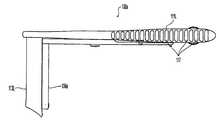
도1은 본 발명에 따르는 다중 블레이드형 리트랙터의 일 실시예의 저면도이다.1 is a bottom view of one embodiment of a multiple blade retractor in accordance with the present invention.
도2는 폐쇄 위치에 있는 도1의 다중 블레이드형 리트랙터의 측면도이다.FIG. 2 is a side view of the multiple blade retractor of FIG. 1 in a closed position. FIG.
도2a는 도2의 다중 블레이드형 리트랙터의 블레이드를 절개한 부분 단면도이다.FIG. 2A is a partial cross-sectional view of the blade of the multi-blade retractor of FIG. 2;
도3은 개방 위치에 있는 도1의 다중 블레이드형 리트랙터의 측면도이다.3 is a side view of the multiple blade retractor of FIG. 1 in an open position;
도4는 다중 블레이드형 리트랙터의 대안 실시예의 측면도이다.4 is a side view of an alternative embodiment of a multi-bladed retractor.
도5는 착탈식 블레이드를 구비한 다중 블레이드형 리트랙터의 다른 실시예의 부분 사시도이다.5 is a partial perspective view of another embodiment of a multi-bladed retractor with removable blades.
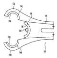
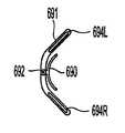
도6은 접이식 리트랙터 블레이드의 단부도이다.6 is an end view of the foldable retractor blade.
도7은 도6의 접이식 리트랙터 블레이드의 내측면을 도시한 측면도이다.FIG. 7 is a side view showing the inner side of the foldable retractor blade of FIG.
도8은 도7의 접이식 리트랙터 블레이드의 외측면을 도시한 측면도이다.FIG. 8 is a side view showing the outer side of the foldable retractor blade of FIG.
도9는 공구를 부착하기 위한 캐뉼러를 구비한 도1의 다중 블레이드형 리트랙터의 블레이드의 부분 저면도이다.9 is a partial bottom view of the blade of the multi-bladed retractor of FIG. 1 with a cannula for attaching a tool.
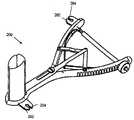
도10은 공구용 부착물을 구비한 도1의 다중 블레이드형 리트랙터의 실시예의 사시도이다.FIG. 10 is a perspective view of an embodiment of the multiple blade retractor of FIG. 1 with a tool attachment. FIG.
도10a는 연결부를 구비한 다중 블레이드형 리트랙터의 다른 실시예의 사시도이다.10A is a perspective view of another embodiment of a multi-blade retractor with connections.
도11은 편의 부재 및 지지 부재를 구비한 다중 블레이드형 리트랙터의 다른 실시예의 저면도이다.Figure 11 is a bottom view of another embodiment of a multi-blade retractor with a biasing member and a support member.
도12는 A-A를 따라 취한 도11의 다중 블레이드형 리트랙터의 단면도이다.12 is a cross-sectional view of the multiple blade retractor of FIG. 11 taken along A-A.
도13은 B-B를 따라 취한 도11의 다중 블레이드형 리트랙터의 지지 부재의 상세도이다.FIG. 13 is a detailed view of the supporting member of the multiple blade retractor of FIG. 11 taken along B-B.
도14는 장력 제한 장치가 제1 위치에 구비된 다중 블레이드형 리트랙터의 실시예의 상세도이다.14 is a detailed view of an embodiment of a multi-blade retractor with a tension limiter in a first position.
도15는 장력 제한 장치가 제2 위치에 구비된 도14의 다중 블레이드형 리트랙터의 실시예의 상세도이다.Figure 15 is a detailed view of the embodiment of the multiple blade retractor of Figure 14 with a tension limiting device provided in a second position.
도16은 다른 장력 제한 장치가 제1 위치에 구비된 다중 블레이드형 리트랙터의 실시예의 상세도이다.Figure 16 is a detailed view of an embodiment of a multi-blade retractor with other tension limiting devices provided in a first position.
도17은 다른 장력 제한 장치가 제2 위치에 구비된 도16의 다중 블레이드형 리트랙터의 실시예의 상세도이다.FIG. 17 is a detailed view of the embodiment of the multi-blade retractor of FIG. 16 with another tension limiter in a second position.
도18은 제4 블레이드를 구비한 다중 블레이드형 리트랙터의 다른 실시예의 평면도이다.18 is a plan view of another embodiment of a multi-blade retractor with a fourth blade.
도19는 도18의 다중 블레이드형 리트랙터의 부분 측면도이다.FIG. 19 is a partial side view of the multiple blade retractor of FIG. 18. FIG.
도20은 도18의 다중 블레이드형 리트랙터의 대안적인 제4 블레이드 부착물의 평면도이다.20 is a top view of an alternative fourth blade attachment of the multi-bladed retractor of FIG.
도21은 대안적인 제4 블레이드 부착물을 구비한 다중 블레이드형 리트랙터의 다른 대안 실시예의 저면도이다.Figure 21 is a bottom view of another alternative embodiment of a multi-bladed retractor with alternative fourth blade attachments.
도22는 도21의 다중 블레이드형 리트랙터의 대안적인 제4 블레이드 부착물의 평면도이다.22 is a top view of an alternative fourth blade attachment of the multi-bladed retractor of FIG. 21.
도23은 다른 대안적인 블레이드 부착물을 구비한 다중 블레이드형 리트랙터의 다른 대안적인 실시예의 저면도이다.Figure 23 is a bottom view of another alternative embodiment of a multiple blade retractor with other alternative blade attachments.
도24는 다른 대안적인 블레이드 부착물을 구비한 다중 블레이드형 리트랙터의 다른 대안적인 실시예의 저면도이다.Figure 24 is a bottom view of another alternative embodiment of a multiple blade retractor with other alternative blade attachments.
도1 내지 도24에 설명된 리트랙터는 다음에 제한되지 않지만, 절개술, 임플란트 삽입술, 나사못 고정술 및 척골 막대 배치술을 포함하는 척추 영역에서의 수술 과정을 수행하기 위해 사용될 수 있다. 비록 이하의 리트랙터에 대한 설명은 주로 척추 수술에 관련된 것이지만, 본 발명의 리트랙터는 다른 유형의 수술 과정에 사용될 수 있음이 이해되어야 한다. 예컨대, 리트랙터는 의사가 피부를 절개함으로써 몸체 내에 접근로를 얻고자 할 때 사용될 수 있으며 수술 기구를 사용하여 환자에 대해 수행되는 수술 과정을 위한 접근 위치를 제공할 수 있다. 특히, 리트랙터는 의사에 의해 수술될 환자 몸체 내의 위치에 대한 수술 기구의 가시성 및/또는 접근을 허용하기위해 연질 조직 또는 기관을 뒤로 젖힐 수 있고 수술 기구가 환 자 몸체 내로 삽입될 수 있도록 절개부를 확장 위치에서 유지할 수 있다.The retractor described in FIGS. 1-24 can be used to perform surgical procedures in the spinal region, including, but not limited to, incision, implant insertion, screw fixation, and ulnar rod placement. Although the description of the following retractors is primarily related to spinal surgery, it should be understood that the retractors of the present invention may be used in other types of surgical procedures. For example, a retractor may be used when a physician wishes to gain access in the body by cutting the skin and may use an surgical instrument to provide an access location for the surgical procedure performed on the patient. In particular, the retractor may be able to flip back soft tissues or organs and allow the surgical instrument to be inserted into the patient's body to allow visibility and / or access of the surgical instrument to a location within the patient's body to be operated by the doctor. It can be kept in the extended position.
또한, 본 명세서에서 설명되는 모든 리트랙터 실시예의 구성 요소는 예컨대, 금속, 플라스틱, 고무 또는 이들 재료의 조합 또는 복합 재료(즉, 둘 이상의 재료로 이루어진 재료)로 제조될 수 있다. 예컨대, 구성 요소는 스테인리스 강, 티타늄, 알루미늄, 합금, 탄소 섬유 복합재 또는 중합체[예컨대, 폴리비닐 클로라이드(PVC), 폴리에틸렌, 다양한 종류의 폴리에스테르, 폴리카보네이트, 테플론 피복 금속, 폴리에테르에테르 케톤(PEEK), 초고분자량 폴리에틸렌(UHMWPE)으로 제조될 수 있다. 또한, 상술한 리트랙터의 구성 요소를 제조하기 위해 다양한 방법이 사용될 수 있으며, 이들 방법으로는 주조, 압출 성형, 사출 성형, 압축 성형, 단조, 가공 또는 트랜스퍼 성형이 있다. 또한, 이들 구성 요소는 예컨대, 아교 접합, 단일 부품으로서 주조 또는 단조, 용접 또는 브레이징에 의해 서로 결합되거나, 나사, 리벳팅 또는 그 밖의 적절한 수단에 의해 기계적으로 결합될 수 있다.In addition, the components of all the retractor embodiments described herein may be made, for example, of metal, plastic, rubber or combinations of these materials or composite materials (ie, materials consisting of two or more materials). For example, the components may be stainless steel, titanium, aluminum, alloys, carbon fiber composites or polymers [eg, polyvinyl chloride (PVC), polyethylene, various types of polyesters, polycarbonates, Teflon-coated metals, polyetherether ketones (PEEK ), And may be made of ultra high molecular weight polyethylene (UHMWPE). In addition, various methods may be used to manufacture the components of the retractor described above, and these methods include casting, extrusion molding, injection molding, compression molding, forging, processing, or transfer molding. In addition, these components may be joined to one another, for example by glue bonding, casting or forging as a single part, welding or brazing, or mechanically joined by screws, riveting or other suitable means.
도1을 참조하면, 다중 블레이드형 리트랙터(100)는 적어도 두 개의 장형부(110R, 110L)를 포함할 수 있다. 그러나, 기술 분야의 당업자는 리트랙터(100)의 다양한 요소에 대해 많은 변경과 대안이 이루어질 수 있음을 안다고 이해되어야 한다.Referring to FIG. 1, the
장형부(110R, 110L)는 집도자에게 가장 인접하고 손잡이부(111R, 111L)를 포함할 수 있는 기부 단부와, 기부 단부에 대향하고 말단부(112R, 112L)를 포함할 수 있는 말단부를 가질 수 있다. 손잡이부(111R, 111L)는 각각의 장형부(110R, 110L)의 기부 단부에 위치될 수 있고 사용자에 의해 파지되도록 구성될 수 있다. 그리 고, 말단부(111R, 110L)는 각각 장형부(110R, 110L)의 말단부에 위치될 수 있다. 또한, 장형부(110R, 110L)는 예컨대 피봇 커넥터(120)에 의해 피봇식으로 연결될 수 있다. 피봇 커넥터(120)는 (대응하는 너트를 구비한) 볼트와, 핀과, 리벳과, 피봇 지점을 제공하는 그 밖의 유사한 수단일 수 있다. 이와 같이, 손잡이부(111R, 111L)와 말단부(112R, 112L)는 서로에 대하여 대응하여 또는 대향되게 이동할 수 있다. 손잡이부(111R, 111L)가 도1에 도시된 바와 같이 서로 가까워질 때, 말단부(112R, 112L)[따라서 서로 대향하는 블레이드(113R, 113L)는 멀리 전개될 수 있다.The
손잡이부(111R, 111L)는 손잡이부(111R 및/또는 111L)에 일체로 형성되거나 결합 가능할 수 있고 사용자의 리트랙터(100)에 대한 파지력을 개선할 수 있는 파지부(117)(도4)를 가질 수 있다. 파지부(117)는 장형부(110R, 110L)와 동일하거나 다른 재료로 제조될 수 있다. 일 실시예에서, 파지부(117)는 손잡이부(111R, 111L) 둘레에 배치되는 재료(예컨대, 플라스틱, 고무 등)의 조각일 수 있다. 다른 실시예에서, 파지부(117)는 손잡이부(111R, 111L) 구조의 일부일 수 있는 융기물, 돌출부 또는 홈이거나, 손잡이부(111R, 111L) 상에 배치되는 별개의 조각들일 수 있다. 예컨대, 도4는 손잡이부(111L) 상에 배치되는 여러 조각의 재료를 도시한다.The
블레이드(113R, 113L)는 각각 장형부(110R, 110L)의 말단부(112R, 112L)에 부착될 수 있다. "블레이드"라 부른다 하더라도 반드시 절개 칼날을 의미하는 것이 아님을 이해하여야 한다. 비록 본 명세서에서 설명되는 여하한 블레이드가 절 개면을 가질 수 있거나 그리고/또는 조직을 절개하기 위해 사용될 수 있지만, 리트랙터 블레이드는 바람직하게는 연질 조직을 잡아서 뒤로 젖히고 연질 조직이 수술 영역으로 진입하는 것을 방지하는 벽으로서 기능한다. 블레이드(113R, 113L)는 각각의 블레이드(113R, 113L)가 다른 블레이드(113R, 113L)에 대해 이동할 수 있도록 각각 말단부(112R, 112L)에 연결될 수 있다. 폐쇄 위치에서, 말단부(112R, 112L)는 서로 접촉할 수 있고 말단부(112R, 112L) 상에 장착되는 블레이드(113R, 113L)는 도10a에 도시된 바와 같이 초기 리트랙터 개구를 한정할 수 있다. 블레이드(113R, 113L)의 형상과 구성에 따라, 개구는 원형 공간일 수 있지만 임의의 형상일 수 있다. 도1에 도시된 바와 같이, 블레이드(113R, 113L)는 오목-볼록면 외형을 가질 수 있지만, 다른 구성을 갖는 블레이드가 사용될 수도 있다. 블레이드의 설계(예컨대, 크기, 형상, 배향)를 결정함에 있어서는 다양한 인자가 고려될 수 있으며, 이들 인자로는 블레이드들이 확장될 때 절개부에서 환자의 몸체에 대한 외상을 최소화하는 것과, 블레이드가 견인된 조직과의 결합으로부터 쉽게 미끄러지지 않을 수 있도록 절개부에서 블레이드를 안정화하는 것과, 각각의 환자에 대해 맞춤성 해부 허용이 있다.The
활주 막대(130)는 활주 막대(130)의 슬롯(131)을 통해 배치될 수 있는 피봇 핀(120)에 의해 장형부(110R, 110L)에 연결될 수 있다. 다시, 활주 블레이드(134)는 활주 블레이드(134)의 내면(136)이 블레이드(113R, 113L)의 외측면(114R, 114L)에 각각 인접할 수 있도록 활주 막대(130)의 말단부(135) 상에 장착될 수 있다. 블레이드(113R, 113L)와 같이 활주 블레이드(134)는 오목-볼록 외형을 가질 수 있 다. 활주 블레이드(134)도 마찬가지로 다른 구성을 가질 수 있다.The
활주 막대(130)의 기지 단부(132)는 핀(133)에 의해 링크(140R, 140L)의 중간 단부(141R, 141L)에 피봇식으로 연결될 수 있다. 자신을 중심으로 링크(140R, 140L)의 회전을 허용하는 한 다른 연결 구성(예컨대, 나사, 볼트)이 핀(133) 대신 사용될 수 있다. 링크(140R, 140L)의 측단부(142R, 142L)는 나사(143R, 143L)에 의해 장형부(110R, 110L)에 피봇식으로 부착될 수 있다. 자신을 중심으로 링크(140R, 140L)의 회전을 허용하는 한 다른 연결 구성(예컨대, 핀, 볼트)이 나사(143R, 143L) 대신 사용될 수 있음을 이해하여야 한다. 후술하는 바와 같이 활주 블레이드(134)의 이동이 대향하는 블레이드(113R, 113L)에 대해 조절될 수 있도록 링크(140R, 140L)의 재배치를 허용하기 위해 구멍(119R, 119L)이 장형부(110R, 110L)에 마련될 수도 있다. 구멍(119R, 119L)에는 나사가 형성되거나 평활할 수 있다. 활주 블레이드(134)는 중간 연결을 포함하는 임의의 직접적 또는 간접적 방법에 의해 장형부(110R, 110L)의 임의의 부분을 따라 연결될 수 있다.The
링크(140R, 140L)는 손잡이부(111R, 111L)를 서로 이동할 경우 장형부(110R, 110L)의 이동에 비례하는 양만큼 블레이드(113R, 113L)로부터 활주 블레이드(134)를 멀리 이동시키도록 활주 막대(130) 그리고 결과적으로 활주 블레이드(134)를 장형부(110R, 110L)에 연결할 수 있다. 집도자가 링크(140R, 140L)들을 서로 다른 구멍(119R, 119L)에 연결할 경우, 활주 블레이드(134)가 장형부(110R, 110L)의 이동에 대해 블레이드(113R, 113L)로부터 멀리 이동할 수 있는 양은 변경될 수 있다. 예컨대, 핀(120)에 인접한 장형부(110R, 110L) 상의 위치에 링크(140R, 140L)를 연 결하면 활주 블레이드(134)는 링크(140R, 140L)가 핀(120)으로부터 멀리 있는 장형부(110R, 110L) 상의 위치에 연결되는 경우보다 블레이드(113R, 113L)로부터 작은 거리만큼 이동하는 결과를 가져올 수 있다. 링크(140R, 140L)의 위치를 변경하면 리트랙터(100)가 폐쇄 위치에 있을 때 블레이드(113R, 113L)에 대한 활주 블레이드(134)의 위치에 영향을 줄 수도 있다.The
또한, 판 스프링(150R, 150L)이 장형부(110R, 110L) 사이에 배치될 수 있으며 나사(151R, 151L)에 의해 장형부(110R, 110L)에 연결될 수 있다. 기술 분야의 당업자라면 이런 연결이 대안으로서 리벳, 용접 또는 그 밖의 체결 기구를 사용하여 이루어질 수 있음을 알아야 한다. 판 스프링(150R, 150L)은 리트랙터 블레이드(113R, 113L)와 활주 블레이드(134)가 폐쇄 위치에 있을 수 있도록 확장 위치에 있는 손잡이부(111R, 111L)를 편의시킬 있다. 다른 실시예에서, 코일 스프링(비도시)이 확장 위치에 있는 손잡이부(111R, 111L)를 편의시키기 위해 사용될 수 있다. 그러나, 그 밖의 구성 요소와 다른 구성 요소와 기구들이 손잡이부(111R, 111L)를 이격되게 편의시키기 위해 사용될 수 있다.In addition,
사용시, 손잡이부(111R, 111L)가 서로에 대해 가까워짐에 따라 링크(140R, 140L)는 중간 단부(141R, 141L)가 기부 방향으로 [즉, 블레이드(113R, 113L)로부터 멀어지게] 이동할 수 있도록 나사(143R, 143L)를 중심으로 회전할 수 있다. 중간 단부(141R, 141L)가 기부쪽으로 이동함에 따라, 이들 중간 단부(141R, 141L)는 핀(133)을 중심으로 피봇 회전해서 활주 막대(130)를 기부쪽으로 당긴다. 활주 막대(130)의 선형 이동은 슬롯(131)과 상호 작용해서 그 내부에서 이동하는 피봇 핀 (120)에 의해 안내된다. 활주 막대(130)가 기부쪽으로 이동함에 따라, 활주 블레이드(134)는 기부 방향으로 이동할 수 있다. 손잡이부(111R, 111L)로부터의 압력이 해제될 때, 판 스프링(150R, 150L)은 손잡이부(111R, 111L)를 확장시킬 수 있다. 그 결과, 장형부(110R, 110L)와 활주 블레이드(130)는 블레이드(113R, 113L)가 아주 인접하게 되고 활주 블레이드(134)의 내측면(136)이 블레이드(113R, 113L)의 외측면(114R, 114L)과 인접할 수 있는 폐쇄 위치로 복귀할 수 있다.In use, as the
블레이드(113R, 113L, 134)를 서로에 대해 선택된 거리에 고정하기 위해 고정 기구가 마련될 수 있다. 도1에 도시된 바와 같이, 고정 기구는 손잡이부(111L)의 내면 상의 플랜지(115)에 핀(161)에 의해 피봇식으로 연결되는 나사 막대(160)를 포함할 수 있다. 나사 막대(160)의 대향하는 단부는 나사 막대(160)의 부분(147)이 손잡이부(111R)를 지나 연장되도록 손잡이부(111R)의 보어(145) 내에 활주 가능하게 수용될 수 있다. 너트(170)가 나사 막대(160)의 부분(147) 상으로 나사 체결되어 손잡이부(110R)에 대해 조여짐으로써, 손잡이부(110R, 110L)가 확장되는 것을 방지할 수 있다. 너트(170)는 도톨도톨한 외면(171)을 가질 수 있으며, 이는 너트(170)를 조이고 푸는 동안 너트(170)에 대한 사용자의 파지력을 개선할 수 있다. 대안으로서, 고정 기구는 나사 막대(160)가 손잡이부(110L)를 통과해서 너트(170)가 손잡이부(110L)와 결합하도록 대향하는 배열 구조로 구성될 수 있다. 기술 분야의 당업자라면 고정 기구가 래칫이거나, "연성 고정" 배열 구조이거나, 기술 분야에서 공지된 임의의 다른 적절한 고정 기구일 수 있음을 알게 될 것이다.Fixing mechanisms may be provided to fix the
폐쇄 위치에서, 블레이드(113R, 113L, 134)는 일반적으로 내경이 약 3 ㎜ 내 지 약 50 ㎜이고, 보다 바람직하게는 약 10 ㎜ 내지 약 16 ㎜이고, 가장 바람직하게는 약 13 ㎜인 원형 개구를 형성한다. 기술 분야의 당업자라면 블레이드(113R, 113L, 134)는 수술 과정을 겪는 환자의 수술 절개부 내로 삽입되어 의료 기구가 탐색, 진단 또는 수술 과정을 수행하기 위해 삽입되는 개구를 형성하도록 확장되기에 적절한 임의의 크기로 될 수 있음을 이해하여야 한다.In the closed position, the
개방 위치에서, 블레이드(113R, 113L, 134)는 예컨대 가로가 약 10 ㎜ 내지 약 150 ㎜ 사이이고 세로가 약 10 ㎜ 내지 약 50 ㎜ 사이이고, 보다 바람직하게는 가로가 약 70 ㎜이고 세로가 약 30 ㎜인 치수를 갖는 접근 개구-예컨대, 대략적으로 삼각형(예컨대, 이등변 삼각형) 또는 4점 개구-를 형성할 수 있다. 개구는 블레이드 구성 및 크기에 따라 다른 형상 및 크기일 수 있다. 또한, 개방 위치에서, 블레이드(113R, 113L) 사이의 거리는 예컨대 약 10 ㎜ 내지 약 150 ㎜ 사이일 수 있다. 활주 블레이드(134)와 블레이드(113R, 113L) 사이의 거리는 예컨대 약 0 ㎜ 내지 약 50 ㎜ 사이일 수 있다.In the open position, the
도2 및 도3에 도시된 바와 같이, 블레이드(113L, 134)는 연질 조직 결합을 용이하게 하기 위해 반경 R을 갖는 외향하는 깔대기형 선단부(116L, 137)를 가질 수 있다. 블레이드(113R)도 반경 R을 갖는 깔대기형 선단부(비도시)를 가질 수 있다. 깔대기형 선단부는 임의의 유형의 곡면 또는 각도일 수 있음을 이해하여야 한다. 일 실시예에서, 깔대기형 선단부는 블레이드의 벽과 각을 이룰 수 있다. 예컨대, 도2a에 도시된 블레이드(134)를 참조하면 깔대기형 선단부(137)는 블레이드(134)의 벽(134b)과 각(118)을 이룰 수 있다. 각(118)은 예컨대 90 내지 180 °사 이, 보다 바람직하게는 135 내지 180 °사이일 수 있다. 하나 이상의 블레이드가 깔대기형 선단부를 가질 수 있거나 어떤 블레이드도 깔대기형 선단부를 갖지 않을 수 있다. 다른 실시예에서, 일부 블레이드는 반경 R을 가질 수 있지만 다른 블레이드들은 각(118)을 가질 수 있다. 또다른 실시예에서, 모든 블레이드들이 반경 R을 갖거나 모든 블레이드들이 각(118)을 가질 수 있다. 그리고, 각 블레이드의 반경 R 및/또는 각(118)은 다른 블레이드의 반경 R 및/또는 각(118)과 동일하거나 다를 수 있다. 임의의 블레이드는 그 전체 길이에 걸쳐 깔대기형이거나 각이 질 수 있다. 깔대기형 선단부는 연질 조직 결합(즉, 환자 조직의 하부면에 대한 파지)을 용이하게 할 수 있으며, 따라서 리트랙터(100)가 절개부로부터 부적절하게 또는 조급하게 이동하거나 미끄러지는 것을 방지할 수 있다. 선단부(167L, 137)와 같은 깔대기형 선단부는 척추의 골조 해부에 리트랙터(100)를 개조하여 사용될 수도 있다.As shown in Figures 2 and 3, the
또한, 블레이드(113R, 113L, 134)는 리트랙터가 사용될 수술 과정에 따라 다양한 형상과 크기를 취할 수 있다. 블레이드(113R, 113L, 134)의 선단부는 척추의 골조 해부에 일치하도록 개조될 수 있다. 예컨대, 블레이드(113R, 113L, 134)는 척수 후궁의 일부와 접촉하도록 구성될 수 있다.In addition, the
이런 일치성을 달성하기 위해, 활주 블레이드(134)의 선단부(137)의 각(α)은 약 0 내지 약 70 °사이, 보다 바람직하게는 약 20 내지 40 °사이일 수 있다. 블레이드(113L)의 선단부(116L)와 블레이드(113R)의 선단부(비도시)의 각(β)은 약 0 내지 약 80 °사이, 보다 바람직하게는 약 30 내지 60 °사이일 수 있다. (각이 형성된 선단부를 포함하는) 블레이드(113R, 113L)의 길이는 약 25 ㎜ 내지 약 200 ㎜ 사이, 보다 바람직하게는 약 80 ㎜ 내지 약 110 ㎜ 사이일 수 있다. (오목-볼록 블레이드가 마련되는) 블레이드(113R, 113L 및/또는 134)의 깔대기형 단부에서의 반경(R)은 약 0 ㎜ 내지 약 100 ㎜ 사이, 보다 바람직하게는 약 0 ㎜ 내지 약 50 ㎜ 사이일 수 있다. 블레이드(113R, 113L 및/또는 134)는 그 말단부로부터 만곡될 수 있으며 만곡부는 블레이드(113R, 113L 및/또는 134)의 약 0 ㎜ 내지 약 30 ㎜ 사이, 보다 바람직하게는 블레이드(113R, 113L 및/또는 134)의 약 0 ㎜ 내지 약 20 ㎜ 사이의 길이에 걸쳐 연장된다. 그리고, 블레이드(113R, 113L)와 블레이드(134)는 특수한 과정과 환자에 적절하게 대략적으로 동일한 길이를 갖거나 서로 다른 조합의 길이를 가질 수 있다.To achieve this consistency, the angle α of the
예컨대, 도2 및 도3에 도시된 바와 같이, 활주 블레이드(134)는 블레이드(113R, 113L)보다 긴 길이를 가질 수 있다. 이런 구성에서, 리트랙터(100)는 측방 리트랙터로서 기능할 수 있다. 측방 리트랙터로서, 예컨대 환자가 배를 대고 누울 때 리트랙터(100)는 리트랙터(100)의 손잡이부(111R, 111L)가 환자의 척추에 대해 각(예컨대, 대략 수직한 각)을 이룰 수 있거나 다르게는 경우 환자의 측면으로 향할 수 있도록 배치될 수 있다. 이런 배향에서, 블레이드(113R, 113L)는 척추 위에 배치될 수 있고, 그 짧은 길이로 인해 척수골과의 접촉이 방지될 수 있다. 길이가 보다 긴 활주 블레이드(134)는 척추의 측면을 따라 배치될 수 있고 환자의 등 안으로 더 깊이 침투할 수 있다.For example, as shown in Figures 2 and 3, the sliding
도4에 도시된 바와 같이, 다른 실시예에서, 활주 블레이드(134)는 블레이드 (113R, 113L)보다 짧을 수 있다. 이런 구성에서 리트랙터(100a)는 중간 리트랙터로서 기능할 수 있다. 중간 리트랙터로서, 예컨대 환자가 배를 대고 누울 때 리트랙터(100a)는 리트랙터(100a)의 손잡이부(111R, 111L)가 환자의 척추에 평행할 수 있도록 배치될 수 있다. 이런 배향에서 활주 블레이드(134)는 척추 위에 배치될 수 있고 그 짧은 길이로 인해 척수골과의 접촉이 방지될 수 있다. 한편, 길이가 보다 긴 블레이드(113R, 113L)는 척추의 측면을 따라 배치될 수 있고 환자의 등 안으로 더 깊이 침투할 수 있다.As shown in FIG. 4, in other embodiments, the
또한, 도1 내지 도3의 리트랙터(100)의 블레이드(113R, 113L 및/또는 134)는 각각 장형부(110R, 110L) 또는 활주 막대(132)에 예컨대, 용접, 브레이징, 납땜에 의해 영구 부착될 수 있거나, 장형부(110R, 110L) 또는 활주 막대(132)와 일체로 형성될 수 있다. 도5에 도시된 대안 실시예에서, 리트랙터(200)의 블레이드(213R, 213L 및/또는 234)는 착탈식일 수 있다. 착탈식 블레이드는 의사가 환자의 해부학적 차이, 수술이 수행될 수 있는 몸체의 부분 및 방사선 투과성이 바람직할 것인지 여부를 포함하는 다양한 인자를 고려해서 다양한 길이, 형상 및/또는 재료의 블레이드를 설치할 수 있도록 허용할 수 있다.In addition, the
블레이드(213R, 213L 및/또는 234)는 각각 돌출부(217R, 217L, 238)를 가질 수 있다. 돌출부(217R, 217L, 238)에는 구멍(281R, 281L, 280) 내에 위치될 수 있는 볼 멈춤쇠(비도시)와 결합하기 위한 홈(218R, 218L, 239)이 마련될 수 있다. 볼 멈춤쇠는 예컨대 볼 베어링(비도시)을 포함할 수 있으며, 이때 볼 베어링은 구멍(281R, 281L, 281) 내외로 이동해서 홈(218R, 218L, 239)과 결합/분리되도록 편 의 수단(예컨대, 스프링)에 작동식으로 연결된다. 구멍(281R, 281L, 281)은 장형부(210R, 210L)의 말단부(212R, 212L)와 활주 막대(235) 내에 위치될 수 있다. 대안 실시예에서, 나사 연결부, 세트 나사, 핀 등과 같이 블레이드(213R, 213L 및/또는 234)를 제거 가능하게 부착하는 다른 수단이 사용될 수 있다. 블레이드(213R, 213L 및/또는 234)는 장형부(210R, 210L) 및/또는 활주 막대(235)에 대해 자유 회전할 수 있거나 블레이드(213R, 213L 및/또는 234)와 장형부(210R, 210L) 및/또는 활주 막대(235) 사이에서 고정된 상대적 배향을 유지하기 위해 장형부(210R, 210L) 및/또는 활주 막대(235)와의 키 연결부를 가질 수 있다.
도6 내지 도8에 도시된 바와 같이, 본 발명의 다른 실시예에서, 리트랙터(100)는 가변 길이 접이식 리트랙터 블레이드(313)를 포함할 수 있다. 가변 길이 블레이드는 착탈식 블레이드가 사용되는 경우 요구될 수 있는 블레이드의 재고를 최소화하면서도 의사가 환자의 해부학적 차이 또는 수행될 수술의 유형을 고려하여 각 블레이드의 길이를 선택할 수 있도록 한다. 접이식 리트랙터 블레이드(313)는 상부 블레이드부(3131)와 하부 블레이드부(3132)를 포함할 수 있다. 하부 블레이드부(3132)는 상부 블레이드부(3131) 내에 배치될 수 있으며 그 내부에서 축 방향으로 활주할 수 있다. 상부 블레이드부(3131)는 하부 블레이드부(3132)의 외부 모서리(3135)를 감쌀 수 있는 립(3134)을 포함할 수 있다. 이와 같은 구조는 축 방향을 제외한 상부 블레이드부(3131)에 대한 하부 블레이드부(3132)의 모든 움직임을 방지할 수 있다. 결합부(3133)는 상부 블레이드부(3131) 내의 구멍(비도시)를 통해 연장될 수 있으며 하부 블레이드부(3132) 내에 선형으로 배치된 일련의 함몰 부(3136) 중 하나에 선택적으로 결합될 수 있다. 일 실시예에서, 하부 블레이드부(3132)를 관통하는 구멍이 함몰부(3136) 대신에 또는 함몰부와 함께 사용될 수 있다. 따라서, 하부 블레이드부(3132)는 상부 블레이드부(3131)에 대해 고정될 수 있다. 본 발명의 일 실시예에서, 결합부(3133)는 상부 블레이드부(3131)의 나사 구멍(비도시) 내에 배치되는 나사일 수 있다.6-8, in another embodiment of the present invention, the
하부 블레이드부(3132)는 접이식 블레이드(313)의 길이를 조절하기 위해 상부 블레이드부(3131) 내에서 축 방향(즉, 위 또는 아래)으로 활주될 수 있다. 그 후, 두 블레이드의 위치는 적절한 함몰부(3136) 내에 결합부(3133)를 배치함으로써 고정될 수 있다. 블레이드의 서로에 대한 위치가 조절 가능할 수만 있다면 상부 블레이드부(3131)에 하부 블레이드부(3132)를 고정하기 위한 임의의 다른 수단이 사용될 수 있다. 예컨대, 상부 블레이드부(3131)에 하부 블레이드부(3132)를 고정하는 것은 래칫 수단, 마찰 끼움부, 다른 블레이드부 내의 선택 가능한 다양한 함몰부 중 하나와 결합하는 한 블레이드부 내의 판 스프링 또는 볼 멈춤쇠의 사용을 포함할 수 있다.The
일반적으로, 상술한 리트랙터 블레이드 중 하나를 제조하기 위해 사용되는 재료를 결정할 때 다양한 인자가 고려될 수 있으며, 이들 인자로는 살균/세척(즉, 병원에서 살균시 사용되는 세척 제품)을 지탱할 능력, 중량, 내구성, 기계적 강도(예컨대, 환자 몸체 내에서 리트랙터를 개방하고 개방 위치에 리트랙터를 유지함으로써 발생하는 응력을 견디는 능력), 세균 형성에 대한 저항성, 제조 용이성 및 비용, 생체 적합성 및 얼룩(즉, 혈액 또는 병원에서 사용되는 다른 화학 제품)에 대 한 저항 능력이 있다. 또한, 비금속성 블레이드(또는, 실제에 있어, 임의의 다른 구성 요소)를 사용하면 오늘날의 영상 기술을 사용하여 수술 지역에 대한 보다 양호한 시각화를 허용할 수 있는 방사선 투과성(즉, x-레이 또는 다른 형태의 방사선에 투명한) 블레이드의 장점을 제공할 수 있다. 또한, 리트랙터의 블레이드 또는 임의의 다른 구성 요소는 빛의 반사를 방지할 수 있고 수술 작업 공간의 시각화를 개선할 수 있는 반사 방지 표면 마무리 및/또는 표면 마무리/피복을 보존할 수 있는 긁힘 방지 피막을 포함할 수 있다.In general, a variety of factors can be considered when determining the materials used to make one of the retractor blades described above, with these factors being the ability to support sterilization / washing (ie, cleaning products used for sterilization in hospitals). , Weight, durability, mechanical strength (e.g., ability to withstand the stresses caused by opening the retractor in the patient's body and holding the retractor in the open position), resistance to bacterial formation, ease of manufacture and cost, biocompatibility and staining It has the ability to resist (ie, blood or other chemicals used in hospitals). In addition, the use of non-metallic blades (or, in fact, any other component) allows for radiopacity (i.e., x-ray or other) that allows for better visualization of the surgical area using today's imaging techniques. It can provide the advantage of a blade) transparent to the form of radiation. In addition, the blade or any other component of the retractor may be anti-reflective surface finish and / or anti-scratch coating that can preserve the surface finish / coating, which can prevent light reflection and improve visualization of the surgical workspace. It may include.
또한, 리트랙터 블레이드의 외측면은 리트랙터가 확장되어 개방될 때 주변 조직에 대한 외상을 최소화하기 위해 부분적으로 또는 완전히 덧대어져 있거나 신축성 재료를 포함할 수 있다. 따라서, 리트랙터 블레이드는 복층으로 구성될 수 있으며, 이때 내층은 보다 강하고 단단한 재료로 구성될 수 있고 외층은 스폰지이거나 패딩될 수 있다. 본 발명의 일 실시예에서, 하나의 층은 다른 층 상에 분사될 수 있다. 이들 층은 예컨대 접합 매개체(예컨대, 접합제), 나사, 쐐기못, 볼트 또는 용접에 의해 서로 연결될 수 있다.In addition, the outer surface of the retractor blade may be partially or fully padded or include elastic material to minimize trauma to surrounding tissue when the retractor is extended and opened. Thus, the retractor blade may consist of multiple layers, wherein the inner layer may be made of a stronger and harder material and the outer layer may be sponge or padded. In one embodiment of the present invention, one layer may be sprayed onto another layer. These layers may be connected to one another by, for example, bonding media (eg, bonding agents), screws, wedges, bolts or welding.
다시 도9를 참조하면, 리트랙터(100)의 블레이드(113R, 113L 또는 134) 중 하나 이상은 예컨대 광원, 흡입/관개 공구 또는 관찰 장치와 같은 수술 동안 사용하기 위한 장치를 부착하기 위해 사용될 수 있는 캐뉼러(1341)를 가질 수 있다. 캐뉼러(1341)는 블레이드(113R, 113L 및/또는 134)를 따라 짧은 길이만큼만 연장되거나 블레이드(113R, 113L 및/또는 134)의 전체 길이에 걸쳐 연장될 수 있다. 또한, 캐뉼러(1341)는 블레이드(113R, 113L 및/또는 134)의 길이를 따라 임의의 위치 에 위치될 수 있고 광원, 흡수/관개 기구 또는 특수 수술 과정에 요구되는 임의의 그 밖의 기구와 같은 공구를 부착하기에 적절한 임의의 직경을 가질 수 있다. 비록 도시되지는 않았지만, 광원은 광 섬유 묶음을 포함할 수 있으며, 이 묶음은 어느 한 캐뉼러(1341) 내에 삽입될 수 있다. 대안으로서, 광원은 블레이드와 일체로 성형되거나 블레이드에 아교 접합 또는 다른 방식으로 접합되어 블레이드(113R, 113L 및/또는 134)에 합체될 수 있다.Referring again to FIG. 9, one or more of the
수술 기구를 부착하는 다른 수단도 가능하다. 예컨대, 도10에 도시된 바와 같이, 가동 아암(1000)이 장형부(110R 및/또는 110L)에 부착될 수 있다. 예컨대, 현미경 또는 그 밖의 유사한 관찰 기구와 같은 수술 기구가 가동 아암(1000)에 제거 가능하게 또는 영구적으로 연결될 수 있다. 가동 아암(1000)은 장형부(110R 및/또는 110L) 상으로 볼트 체결되거나 파지될 수 있으며 장형부(110R 및/또는 110L)를 따라 제거 가능하게 부착되고 그리고/또는 이동 가능할 수 있다. 대안으로서 가동 아암(1000)은 장형부(110R 및/또는 110L)에 영구 부착될 수 있다. 가동 아암(1000)은 볼 또는 소켓식 분절 아암, 가요성 아암 또는 기구가 3중 블레이드 리트랙터(100)에 대해 부착되어 이동될 수 있도록 하는 다른 장치일 수 있다.Other means of attaching surgical instruments are possible. For example, as shown in FIG. 10,
도10a의 실시예에서, 리트랙터(200)는 지지 구조(비도시)와 결합하는 데 사용될 수 있는 하나 이상의 연결부(202)를 포함할 수 있다. 강성이거나 가요성일 수 있는 지지 구조(예컨대, 신축 아암)는 수술 동안 환자에 대해 리트랙트(200)를 적소에 유지하기 위해, 예컨대 수술 테이블에 연결될 수 있다. 연결부(202)는 임의의 형상 또는 크기일 수 있으며 다른 구성 요소(비도시)를 수용하기 위한 개구 (204)를 가질 수 있다. 대안으로서, 연결부(202)는 개구(204)를 갖지 않을 수 있다. 또한, 연결부(202)는 다른 구성 요소(비도시)의 클립 또는 후크 결합부와 결합하기 위한 클립 또는 후크(비도시)를 가질 수 있다. 연결부(202)는 리트랙터(200)와 일체이거나 이에 연결될 수 있는 별개의 부품일 수 있다. 그러나, 연결부(202)가 다른 구성 요소에 리트랙터(200)를 연결하기 위해 사용될 수 있기만 하다면 여하한 구성의 연결부(202)도 가능함을 이해하여야 한다.In the embodiment of FIG. 10A, the
도11 내지 도13에는 리트랙터의 다른 실시예가 도시되어 있다. 리트랙터(500)는 도1 내지 도3의 리트랙터(100)와 유사하게 동작할 수 있다. 그리고, 리트랙터(100)와 마찬가지로 리트랙터(500)의 구조는 블레이드(513R, 513L)의 이동에 관련되어 활주 블레이드(534)의 행정이 변경될 수 있도록 한다. 이런 구조는 집도자가 수술 과정의 필요에 따라 수술 개구의 치수를 변경할 수 있도록 하는 장점을 제공한다. 구체적으로, 복수의 리세스(519R, 519L) 쌍이 장형부(510R, 510L)의 소정 이동에 관련하여 활주 막대(530)의 행정을 변경하기 위해 링크(540R, 540L)의 측방 단부(542R, 542L)를 선택적으로 위치시키기 위해 마련될 수 있다. 링크(540R, 540L)의 측방 단부(542R, 542L)는 리세스(519R, 519L) 내에 배치될 수 있는 일체형 핀(544R, 544L)에 의해 장형부(510R, 510L)에 피봇식으로 부착될 수 있다. 일체형 핀(544R, 544L)은 리세스(519R, 519L) 내에 핀(544R, 544L)을 보유하도록 도울 수 있는 일체형 캡(545R, 545L)이 씌워질 수 있다.11-13, another embodiment of a retractor is shown. The
피봇 핀(520)에 인접한 한 쌍의 리세스(519R, 519L)에 핀(544R, 544L)을 배치함으로써 핀(544R, 544L)은 장형부(510R, 510L)의 소정 이동에 대해 서로에 대해 짧은 거리만큼 멀리 이동하는 결과를 가져올 수 있다. 또한 핀(544R, 544L)을 이와 같이 배치함으로써 링크(540R, 540L) 사이의 각도가 감소하는 결과를 가져올 수 있다. 이들 인자로 인해 활주 블레이드(534)의 행정은 짧아 질 수 있다. 반대로, 활주 블레이드(534)의 행정이 길어지면 핀(544R, 544L)은 피봇 핀(520)에 더 인접한 한 쌍의 리세스(519R, 519L) 내에 배치되는 결과가 된다. 예컨대, 활주 블레이드(534)의 행정은 일체형 핀(544R, 544L)이 피봇 핀(520)에 가장 인접한 리세스(519R, 519L) 내로 삽입될 때 약 10 ㎜일 수 있고 일체형 핀(544R, 544L)이 피봇 핀(520)으로부터 가장 멀리 있는 리세스(519R, 519L) 내로 삽입될 때 약 20 ㎜일 수 있다.By placing the
또한, 코일 스프링(555)은 핀(533)을 에워쌀 수 있고 코일 스프링 단부(556R, 556L)는 피봇 핀(520)에 가장 인접한 링크(540R, 540L)의 측면과 결합할 수 있다. 스프링(555)의 편의력은 장형부(510R, 510L)의 손잡이부(511R, 511L)를 이격되게 편의시킬 뿐 아니라 리세스(519R, 519L) 내에 일체형 핀(544R, 544L)을 유지하는 역할을 할 수 있다. 코일 스프링(555)은 손잡이부(511R, 511L)를 이격되게 편의시키기 위해 (상술하고 도1에 도시된) 하나 이상의 판 스프링과 함께 사용될 수도 있다.In addition,
리트랙터는 도11 및 도13에 도시된 바와 같이 지지 부재(590R, 590L)를 포함할 수도 있다. 지지 부재(590R, 590L)는 블레이드(513R, 513L, 534)가 환자에게 삽입된 후 환자 몸체 상에 리트랙터(500)를 지지하기 위해 사용될 수 있다. 삽입시, 손잡이부(511R, 511L)는 그 중량으로 인해 환자쪽으로 기울어 질 수 있게 되 며, 이는 블레이드(513R, 513L 및/또는 534)가 환자 내에서 이동할 수 있도록 한다. 지지 부재(590R, 590L)는 연장될 수 있으며 손잡이부(511R, 511L)의 중량으로 인해 발생되는 여하한 이동을 저지하기 위해 환자 몸체 상에 안착될 수 있다. 그리고, 지지 부재(590R, 590L)는 나사(591R, 591L)에 의해 장형부(510R, 510L) 상에 피봇식으로 장착될 수 있지만, 피봇 연결을 제공하는 리벳 또는 그 밖의 수단도 나사(591R, 591L) 대신 사용될 수 있다. 또한, 지지 부재(590R, 590L)는 지지 부재(590R, 590L)가 장형부(510R, 510L)에 대해 어떤 각도(예컨대, 90°)만큼 피봇될 때 환자 몸체 상에 안착될 수 있는 발 형상부(592R, 592L)를 가질 수 있다. 도13에 도시된 바와 같이, 리세스(593R, 594L)와 장형부(510R, 비도시) 상의 유사한 리세스부는 지지 부재(590R, 590L)에 대해 [590L이 리세스(593L)에 배치될 때의] 수용 위치와 [590L이 리세스(594L)에 배치될 때의] 별도의 전개 위치를 제공하기 위해 장형부(510R, 510L) 내에 마련될 수 있다. 이들 리세스는 장형부(510R, 510L)와 평행하거나 각(예컨대, 90°)을 이루며 배향될 수 있으며 수용 또는 전개 위치에 지지 부재(590R, 590L)를 일시적으로 고정하는 역할을 할 수 있다.The retractor may include
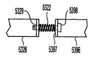
리트랙터는 또한 도14 및 도15에 도시된 바와 같이 활주 블레이드 장력 제한 장치를 포함할 수 있다. 본 실시예에서, 스프링(5322)은 제3 블레이드 활주 막대(530)에 연결될 수 있으며 견인 동안 제3 블레이드(534)(도11)에 의해 조직에 가해지는 힘의 양을 제한할 수 있다. 리트랙터인 조직에 인가되는 힘이 스프링 힘보다 큰 경우, 스프링은 연장되며 제3 블레이드(534)는 정지 상태를 유지하거나 조금만 이동함으로써 조직 손상 가능성을 줄일 수 있다. 본 실시예의 리트랙터의 경우, 활주 막대(530)는 코일 스프링(5322)의 말단부(5323)에 부착하기 위한 부착 수단(5321)(예컨대, 루프)을 갖는 단축된 기부 단부(5320)를 포함할 수 있다. 스프링(5322)의 기부 단부(5324)는 제2 부착 수단(5391)(예컨대, 루프)에 의해 커넥터(5390)에 부착될 수 있다. 핀(533)은 링크(540R, 540L)에 커넥터(5390)를 피봇식으로 연결할 수 있다. 따라서, 손잡이부(511R, 511L)가 서로 가까워지면, 제3 블레이드(534)는 조직에 가해지는 힘이 (선택된 스프링 크기에 대응하는) 소정 값을 초과할 때까지 리트랙터(500)의 기부 단부쪽으로 이동할 수 있다. 조직 상에 가해지는 힘이 스프링 힘과 동일하게 된 후의 지점에서, 스프링은 연신될 수 있고 블레이드(534)는 정지된 상태로 유지되거나 단지 조금만 이동할 수 있다. 이와 같은 구조는 조직 손상을 방지할 수 있다. 이런 소정의 최대 조직력은 수술 과정을 수행하기에 앞서 의사에게 선택할 다양한 스프링을 제공함으로써 제어될 수 있다.The retractor may also include a slide blade tension limiter as shown in FIGS. 14 and 15. In this embodiment, the
대안 실시예에서, 슬리브(5392)는 활주 막대(530)와 커넥터(5390) 사이에 고정된 연결부를 형성함으로써 활주 블레이드 제한 장치가 덮힐 수 있도록 마련될 수 있다. 슬리브(5392)는 기부 주연 슬롯(5393)과 말단 주연 슬롯(5325)을 가질 수 있다. 커넥터(5390) 상의 핀(5395)은 슬롯(5393)과 결합함으로써 커넥터(5390) 상에 슬리브(5392)를 보유할 수 있도록 함과 동시에 여전히 슬리브(5392)가 커넥터(5390)를 중심으로 회전할 수 있도록 한다. 종방향 슬롯(5326)은 슬리브(5392)의 말단부(5396)가 기부 단부(5320) 상에서 핀(5327) 위로 활주될 수 있도록 한다. 그 후, 슬리브(5392)는 활주 막대(530)의 기부 단부(5320) 상에 보유될 수 있도록 회전될 수 있다. 도15에 도시된 이런 구성에서, 활주 막대(530)와 커넥터(5390)는 리트랙터가 도1 내지 도3의 리트랙터(100)과 유사하게 동작할 수 있도록 고정된 관계로 유지될 수 있다. 슬리브는 활주 막대(530)와 커넥터(5390) 사이의 간격에 걸쳐 비탄성 브리지를 제거 가능하게 제공하는 수단으로서 도시되지만, 예컨대 커넥터(5390)에 제거 가능하게 또는 영구적으로 고정될 수 있고 후술하는 바와 같이 활주 막대(530) 등의 일부에 나사 체결(즉, 결합되거나 분리)될 수 있다.In alternative embodiments, the
도16 및 도17은 활주 막대(530)에 의해 절개부에 인가되는 힘을 제한하기 위한 다른 수단을 도시한다. 수평 부재(5328)가 활주 막대(530)의 기부 단부에 부착될 수 있으며 그 기부 단부에 나사식 수납 부재(5329)를 가질 수 있다. 부재(5396)는 핀(533)으로부터 수직 부재(5397)까지 연장될 수 있다. 스프링(5322)은 도14에 도시된 활주 블레이드 장력 제한 장치와 동일한 방식으로 제3 블레이드(534)에 의해 절개부에 인가되는 힘을 제한하기 위해 수직 부재(5397) 및 나사식 수납 부재(5329)를 연결할 수 있다.16 and 17 show other means for limiting the force applied by the
도16 및 도17의 힘 제한 장치는 덮힐 수 있다. 수직 부재(5397)는 관통 구멍(5400)을 가질 수 있으며 수납 부재(5329)는 나사 구멍(5402)을 가질 수 있다. 연결 요소(5398)(예컨대, 나사)가 수직 부재(5397)의 구멍을 통해 삽입되어 수납 부재(5329)의 나사 구멍에 나사 체결될 수 있다. 따라서, 부재(5396)는 활주 막대(530)에 대해 고정될 수 있다. 활주 블레이드(534)에 의해 절개부에 인가되는 힘을 제한하기 위해 다른 방법 및 기구가 사용될 수 있음을 주목해야 한다. 마찬가지로, 이와 같은 장력 제한 기구를 덮기 위해 다른 배열 구조가 사용될 수 있다.The force limiting device of FIGS. 16 and 17 may be covered. The
도18 및 도19는 활주 블레이드(634)에 대향하여 위치될 수 있는 착탈 가능하 고 독립적으로 이동 가능한 제4 블레이드(690)를 구비한 리트랙터(600)의 실시예를 도시한다. 착탈 가능한 것으로 도시되었지만, 제4 블레이드(690)는 영구 부착될 수도 있다. 착탈 가능한 제4 블레이드(690)는 의사가 리트랙터(600)에 의해 형성된 개구의 형상과 치수를 추가로 변경할 수 있도록 한다. 제4 블레이드(690)는 피봇 핀(692R, 692L)에 의해 슬롯 아암(691R, 691L)에 부착될 수 있다. 그러나, 리트랙터(600)에 제4 블레이드(690)를 부착하기 위한 다른 수단도 가능하다. 또한, 제4 블레이드(690)는 상술한 블레이드의 모든 특징을 가질 수 있다. 예컨대, 제4 블레이드(690)는 깔대기형 단부를 가질 수 있거나, 블레이드(313)(도6 내지 도8)와 마찬가지로 조절 가능할 수 있거나, 캐뉼러(1341)(도9)와 유사한 캐뉼러를 가질 수 있다. 아암(691R, 691L)의 슬롯(694R, 694L)을 거쳐 연장되는 나사(693R, 693L)가 장형부(610R, 610L)에 아암(691R, 691L)을 부착하기 위해 사용될 수 있다. 나사(693R, 693L)는 장형부(610R, 610L)의 나사 구멍(비도시)에 나사 체결될 수 있다. 볼트와 같은 다른 구성 요소가 나사(693R, 693L) 대신 사용될 수 있다. 기술 분야의 당업자에게는 리트랙터(600)에 제4 블레이드(690)를 연결하는 여하한 방법이 가능함이 자명할 것이다.18 and 19 show an embodiment of a
사용시, 의사는 나사(693R, 693L)를 사용하여 장형부(610R, 610L)에 아암(691R, 691L)을 느슨하게 부착할 수 있다. 그 후, 의사는 환자 내에 있는 리트랙터(600)를 개방해서 고정할 수 있고 제4 블레이드(690)를 원하는 위치로 수동으로 이동시킬 수 있다. 제4 블레이드(690)는 아암(691R, 691L)이 적소에 고정될 때까지 나사(693R, 693L)가 회전되는 동안 원하는 위치에 보유될 수 있다. 따라서, 네 지점으로 된 정사각형 또는 대략 원형인 개구가 형성될 수 있다. 블레이드(613R)로부터 블레이드(613L)까지의 치수는 예컨대 약 10 ㎜ 내지 약 150 ㎜ 사이일 수 있다. 그리고, 활주 블레이드(634)로부터 제4 블레이드(690)까지의 치수는 약 10 ㎜ 내지 약 70 ㎜ 사이일 수 있다.In use, the surgeon can loosely attach the
도20은 리트랙터(600)에 제4 블레이드(690)를 연결하는 다른 수단을 도시한다. 블레이드(690)는 각각의 단부에 피봇 핀을 갖기 보다 그 중심부에 마련되는 단일한 피봇(692)과 슬롯(694R, 694L)을 가질 수 있는 단일체 아암(691)을 가질 수 있다. 도20에 도시된 배열 구조는 도18 및 도19와 관련하여 상술한 것과 동일한 방식으로 사용될 수 있다. 그러나, 도18 및 도19에 도시된 배열 구조와 달리 도20의 제4 블레이드(690)는 아암(691)이 고정된 후 피봇 회전하도록 될 수 있다. 대안으로서, 피봇 핀(692)은 제4 블레이드(690)가 적소에 유지되도록 고정될 수 있다.20 shows another means of connecting the
도21 및 도22는 리트랙터(700)에 영구적으로 또는 착탈 가능하게 부착될 수 있는 제4 블레이드(790)를 포함하는 리트랙터(700)의 다른 실시예를 도시한다. 제4 블레이드(790)는 예컨대 용접, 브레이징 또는 리벳 또는 나사(비도시)와 같은 기계적 연결부에 의해 아암(791)에 연결될 수 있다. 아암(791)은 다시 커넥터(793R, 793L)에 의해 장형부(710R, 710L) 상의 탭(795R, 795L)에 부착될 수 있다. 커넥터(793R, 793L)는 아암(791)의 슬롯(794R, 794L) 내에서 활주할 수 있다. 핀, 나사 또는 볼트를 포함하는 다양한 구성 요소가 커넥터(793R, 793L)로서 사용될 수 있다.21 and 22 illustrate another embodiment of a
사용시, 의사는 커넥터(793R, 793L)를 사용하여 장형부(710R, 710L)에 아암(791)을 느슨하게 부착할 수 있다. 그 후, 리트랙터(700)를 개방해서 고정한 후, 의사는 [커넥터(793R, 793L)가 슬롯(794R, 794L) 내에서 이동할 수 있도록 아암(791)을 전후로 이동시킴으로써] 제4 블레이드(790)를 위치로 수동으로 이동시킬 수 있고 커넥터(793R, 793L)를 조이면서 제4 블레이드(790)를 적소에 보유할 수 있다. 커넥터(793R, 793L)가 완전히 조여진 후, 제4 블레이드(790)는 위치에 고정될 수 있다. 제4 블레이드(790)는 예컨대 깔대기형 단부, [예컨대, 도6 내지 도8의 블레이드(313)와 유사한] 조절 가능성을 포함하는 상술한 블레이드의 모든 특징을 가질 수 있으며, 다양한 기구(도9)를 유지하기 위한 캐뉼러를 가질 수도 있다.In use, the surgeon may loosely attach the
도22에 도시된 바와 같이, 아암(791)은 도21의 직선형 아암(791) 대신 각형부(796R, 796L)을 가질 수 있다. 각형부(796R, 796L)는 손잡이부(711R, 711L)가 서로 가까워짐에 따라 제4 블레이드(790)가 말단 방향으로 이동할 수 있도록 하거나 장형부(710R, 710L)가 서로에 대해 분리되어 이동함에 따라 기부 방향으로 이동할 수 있도록 한다. 각형부(796R, 796L)는 다양한 길이일 수 있으며 광범위한 이동을 허용하기 위해 서로에 대해 다양한 각을 형성할 수 있다.As shown in FIG. 22, the
도23은 다른 블레이드들이 이동될 때 이동할 수 있는 제4 블레이드(890)를 구비하는 리트랙터(800)의 실시예를 도시한다. 장형부(810R, 810L)는 장형부(810R, 810L)와 일체로 형성될 수 있거나 나사 또는 그 밖의 적절한 기계적 수단에 의해 장형부(810R, 810L)에 제거 가능하게 부착될 수 있는 연장 아암(897R, 897L)을 가질 수 있다. 연장 아암(897R, 897L)은 핀(893R, 893L)을 중심으로 피봇 회전 할 수 있도록 아암(898R, 898L)에 연결될 수 있다. 또한, 아암(898R, 898L)은 중심 핀(893C)에서 부재(899)에 피봇식으로 부착될 수 있다. 그리고, 블레이드(890)는 예컨대 용접, 브레이징 또는 (예컨대, 리벳, 나사, 볼트 등과 같은) 기계적 연결부에 의해 부재(899)에 부착될 수 있다. 사용시, 장형부(810R, 810L)의 손잡이부(811R, 811L)는 서로에 대해 가까워질 수 있고 핀(893R, 893L)은 멀리 이격되게 이동될 수 있다. 그 결과, 아암(898R, 898L)은 핀(893R, 893L)을 중심으로 피봇 회전함으로써 제4 블레이드(890)와 함께 부재(899)를 활주 블레이드(834)로부터 멀리 이동시킨다. 제4 블레이드(890)가 이동함으로써 리트랙터(800)는 도18 내지 도22의 리트랙터보다 사용하기 용이하게 될 수 있다(즉, 의사가 제4 블레이드를 조절하는 추가적인 단계를 수행할 필요가 없어진다). 그러나, 리트랙터(800)는 블레이드들이 서로에 대한 설정 관계에 있기 때문에 사용시 덜 유연할 수 있다. 제4 블레이드(890)는 예컨대 깔대기형 단부, [예컨대, 도6 내지 도8의 블레이드(313)와 유사한] 조절 가능성을 포함하는 상술한 블레이드의 모든 특징을 가질 수 있으며, 다양한 기구(도9)를 유지하기 위한 캐뉼러를 가질 수도 있다.Figure 23 illustrates an embodiment of a
도24는 다른 블레이드들이 이동할 때 제4 블레이드(990)가 이동할 수 있는 다른 리트랙터(900)를 도시한다. 장형부(910R, 910L)는 연장 아암(997R, 997L)을 가질 수 있다. 손잡이부(911R, 911L)가 서로에 대해 가까워짐에 따라, 아암(998)은 연장 아암(997L)의 말단부에서 핀(993L)을 중심으로 피봇 회전할 수 있고 핀(993R)은 아암(998)의 슬롯(994) 내에서 활주할 수 있다. 아암(998)이 이동함으로써 핀(993C)에 의해 아암(998)에 부착될 수 있는 제4 블레이드(990)는 활주 블레이 드(934)로부터 멀리 말단 방향으로 이동하게 될 수 있다. 제4 블레이드(990)는 핀(993C)을 중심으로 피봇 이동할 수 있거나 아암(998)에 대해 고정될 수 있다.24 shows another
또한, 본 명세서에 설명된 리트랙터는 개별 구성 요소로서 마련될 수 있거나 키트의 일부로서 마련될 수 있다. 키트는 본 명세서에 설명된 하나 이상의 리트랙터와, 하나 이상의 이중-블레이드형 리트랙터 또는 이중 블레이드 힌지형 리트랙터를 포함할 수 있다. 이중-블레이드 및 이중 블레이드 힌지형 리트랙터는 임의의 수의 의료 기구 가공업자로부터 얻어질 수 있다. 키트의 일부로서, 리트랙터에는 힘-제한 활주 블레이드 실시예를 위한 다양한 스프링뿐만 아니라 다양한 길이, 재료 및 표면 구성을 포함하는 복수의 교체 가능한 블레이드가 마련된다. 키트는 광원, 흡입/관개 공구, 편평 블레이드, 다양한 길이의 블레이드 및 다양한 결합 각도의 블레이드도 포함할 수 있다.In addition, the retractors described herein may be provided as individual components or may be provided as part of a kit. The kit may include one or more retractors described herein and one or more double-bladed retractors or dual blade hinged retractors. Double-blade and double blade hinged retractors may be obtained from any number of medical instrument processors. As part of the kit, the retractor is provided with a plurality of replaceable blades that include various lengths, materials, and surface configurations, as well as various springs for force-limited sliding blade embodiments. The kit may also include light sources, suction / irrigation tools, flat blades, blades of various lengths and blades of various mating angles.
상술한 설명과 도면은 본 발명의 바람직한 실시예에 대한 것이지만, 첨부한 특허청구범위에 정의된 본 발명의 정신 및 범위에서 벗어나지 않은 다양한 추가, 개조 및 대체가 이루어질 수 있음을 이해하게 될 것이다. 특히, 본 발명은 본 발명의 정신 또는 요지에서 벗어나지 않은 다른 특수한 형태, 구조, 배열, 비율로 구현될 수 있으며 다른 요소, 재료 및 구성 요소를 구비할 수 있음은 기술 분야의 당업자에게 자명할 것이다. 기술 분야의 당업자라면 본 발명의 원리에서 벗어나지 않은 특수한 환경 및 작동 조건에 특히 적합하게 본 발명이 그 구조, 배열, 비율, 재료 및 구성 요소를 다양하게 변경하여 사용될 수 있으며 본 발명의 실무에서 이와 다르게 사용될 수 있음을 알 것이다. 따라서, 본 명세서에서 논의되는 실시예 들은 제한적이 아닌 예시적인 것으로 간주되어야 하며, 본 발명의 범위는 첨부된 특허청구범위에 의해 지시되며 상술한 설명에 제한되지 않는다.While the foregoing description and drawings are of preferred embodiments of the present invention, it will be understood that various additions, modifications, and substitutions may be made without departing from the spirit and scope of the invention as defined in the appended claims. In particular, it will be apparent to those skilled in the art that the present invention may be embodied in other specific forms, structures, arrangements, ratios, and other elements, materials, and components, without departing from the spirit or spirit of the invention. Those skilled in the art will appreciate that the present invention may be used in various modifications to its structure, arrangement, proportions, materials and components, and is particularly suitable for special environments and operating conditions that do not depart from the principles of the present invention. It will be appreciated that it can be used. Accordingly, the embodiments discussed herein are to be considered as illustrative and not restrictive, the scope of the invention being indicated by the appended claims and not limited to the foregoing description.
Claims (57)
Translated fromKoreanApplications Claiming Priority (2)
| Application Number | Priority Date | Filing Date | Title |
|---|---|---|---|
| US49480303P | 2003-08-14 | 2003-08-14 | |
| US60/494,803 | 2003-08-14 |
Publications (1)
| Publication Number | Publication Date |
|---|---|
| KR20060107507Atrue KR20060107507A (en) | 2006-10-13 |
Family
ID=34193241
Family Applications (1)
| Application Number | Title | Priority Date | Filing Date |
|---|---|---|---|
| KR1020067003046AWithdrawnKR20060107507A (en) | 2003-08-14 | 2004-08-16 | Multi Blade Retractor |
Country Status (11)
| Country | Link |
|---|---|
| US (1) | US7481766B2 (en) |
| EP (2) | EP1659928B1 (en) |
| JP (1) | JP2007502175A (en) |
| KR (1) | KR20060107507A (en) |
| CN (1) | CN1863479A (en) |
| AU (1) | AU2004264983A1 (en) |
| BR (1) | BRPI0413577A (en) |
| CA (1) | CA2535391A1 (en) |
| ES (1) | ES2639414T3 (en) |
| WO (1) | WO2005016131A2 (en) |
| ZA (1) | ZA200601334B (en) |
Cited By (2)
| Publication number | Priority date | Publication date | Assignee | Title |
|---|---|---|---|---|
| KR20190097437A (en)* | 2018-02-12 | 2019-08-21 | 하재성 | Retrector for rhinoplastic method of the nonincisional nose |
| KR20210048207A (en)* | 2019-10-23 | 2021-05-03 | 주식회사 엔도비전 | Spine Retractor |
Families Citing this family (229)
| Publication number | Priority date | Publication date | Assignee | Title |
|---|---|---|---|---|
| WO2001037728A1 (en) | 1999-11-24 | 2001-05-31 | Nuvasive, Inc. | Electromyography system |
| EP1417000B1 (en) | 2001-07-11 | 2018-07-11 | Nuvasive, Inc. | System for determining nerve proximity during surgery |
| JP2005503857A (en) | 2001-09-25 | 2005-02-10 | ヌバシブ, インコーポレイテッド | Systems and methods for performing surgical procedures and surgical diagnosis |
| JP3913506B2 (en)* | 2001-09-26 | 2007-05-09 | 三洋電機株式会社 | Disc recording or playback device with a tray that can be moved up and down |
| US8147421B2 (en) | 2003-01-15 | 2012-04-03 | Nuvasive, Inc. | System and methods for determining nerve direction to a surgical instrument |
| US7582058B1 (en) | 2002-06-26 | 2009-09-01 | Nuvasive, Inc. | Surgical access system and related methods |
| US8137284B2 (en) | 2002-10-08 | 2012-03-20 | Nuvasive, Inc. | Surgical access system and related methods |
| US7946982B2 (en)* | 2002-10-25 | 2011-05-24 | K2M, Inc. | Minimal incision maximal access MIS spine instrumentation and method |
| US7850608B2 (en) | 2002-10-25 | 2010-12-14 | K2M, Inc. | Minimal incision maximal access MIS spine instrumentation and method |
| US6849064B2 (en)* | 2002-10-25 | 2005-02-01 | James S. Hamada | Minimal access lumbar diskectomy instrumentation and method |
| US7887482B2 (en)* | 2002-10-25 | 2011-02-15 | K2M, Inc. | Minimal access lumbar diskectomy instrumentation and method |
| US7935054B2 (en)* | 2002-10-25 | 2011-05-03 | K2M, Inc. | Minimal access lumbar diskectomy instrumentation and method |
| US7691057B2 (en) | 2003-01-16 | 2010-04-06 | Nuvasive, Inc. | Surgical access system and related methods |
| US7819801B2 (en) | 2003-02-27 | 2010-10-26 | Nuvasive, Inc. | Surgical access system and related methods |
| US7905840B2 (en) | 2003-10-17 | 2011-03-15 | Nuvasive, Inc. | Surgical access system and related methods |
| JP4463819B2 (en) | 2003-09-25 | 2010-05-19 | ヌヴァシヴ インコーポレイテッド | Surgical access system |
| US8313430B1 (en) | 2006-01-11 | 2012-11-20 | Nuvasive, Inc. | Surgical access system and related methods |
| US9795367B1 (en) | 2003-10-17 | 2017-10-24 | Nuvasive, Inc. | Surgical access system and related methods |
| US8038611B2 (en) | 2003-12-18 | 2011-10-18 | Depuy Spine, Inc. | Surgical methods and surgical kits |
| US20060084843A1 (en)* | 2004-09-30 | 2006-04-20 | Codman & Shurtleff, Inc. | Disposable padding for a self-retaining retraction device |
| WO2006042241A2 (en) | 2004-10-08 | 2006-04-20 | Nuvasive, Inc. | Surgical access system and related methods |
| WO2006058221A2 (en) | 2004-11-24 | 2006-06-01 | Abdou Samy M | Devices and methods for inter-vertebral orthopedic device placement |
| US7427264B2 (en)* | 2005-04-22 | 2008-09-23 | Warsaw Orthopedic, Inc. | Instruments and methods for selective tissue retraction through a retractor sleeve |
| US20060287584A1 (en)* | 2005-06-16 | 2006-12-21 | Javier Garcia-Bengochia | Surgical retractor extensions |
| US8328851B2 (en) | 2005-07-28 | 2012-12-11 | Nuvasive, Inc. | Total disc replacement system and related methods |
| US7566302B2 (en)* | 2005-07-28 | 2009-07-28 | Synthes Usa, Llc | Expandable access device |
| US7846093B2 (en)* | 2005-09-26 | 2010-12-07 | K2M, Inc. | Minimally invasive retractor and methods of use |
| US8251902B2 (en) | 2005-10-17 | 2012-08-28 | Lanx, Inc. | Pedicle guided retractor system |
| JP2009512174A (en)* | 2005-10-17 | 2009-03-19 | デントゾーン カンパニー リミテッド | Oral lighting device |
| US8480576B2 (en) | 2005-12-07 | 2013-07-09 | Faheem A. Sandhu | Access system for minimally invasive spinal surgery |
| US7981031B2 (en) | 2006-01-04 | 2011-07-19 | Depuy Spine, Inc. | Surgical access devices and methods of minimally invasive surgery |
| US7758501B2 (en)* | 2006-01-04 | 2010-07-20 | Depuy Spine, Inc. | Surgical reactors and methods of minimally invasive surgery |
| US7955257B2 (en) | 2006-01-05 | 2011-06-07 | Depuy Spine, Inc. | Non-rigid surgical retractor |
| US7985179B2 (en) | 2006-01-23 | 2011-07-26 | Pioneer Surgical Technology | Retraction apparatus and method of use |
| ATE480192T1 (en)* | 2006-02-01 | 2010-09-15 | Arthrex Inc | HANDLE FOR SURGICAL INSTRUMENTS |
| US8876687B2 (en)* | 2006-03-08 | 2014-11-04 | Zimmer Spine, Inc. | Surgical retractor and retractor assembly |
| US7766937B2 (en) | 2006-03-13 | 2010-08-03 | Mini-Lap Technologies, Inc. | Minimally invasive surgical assembly and methods |
| US8430813B2 (en)* | 2006-05-26 | 2013-04-30 | Depuy Spine, Inc. | Illuminated surgical access system including a surgical access device and integrated light emitter |
| US20070282170A1 (en)* | 2006-05-30 | 2007-12-06 | Sundaram Ravikumar | Rake Retractor and Needle Assembly for Minimally Invasive Surgical Applications |
| US7892174B2 (en)* | 2006-07-19 | 2011-02-22 | Zimmer Spine, Inc. | Surgical access system and method of using the same |
| US8262569B2 (en)* | 2006-07-19 | 2012-09-11 | Zimmer Spine, Inc. | Surgical access system and method of using the same |
| US8142355B2 (en)* | 2006-09-25 | 2012-03-27 | Spinal Elements, Inc. | Surgical tissue retractor |
| US7922658B2 (en)* | 2006-11-09 | 2011-04-12 | Ebi, Llc | Surgical retractor device and related methods |
| US7931589B2 (en) | 2006-11-09 | 2011-04-26 | Ebi, Llc | Surgical retractor device and related methods |
| US20080132766A1 (en)* | 2006-12-05 | 2008-06-05 | Zimmer Spine, Inc. | Surgical Access System And Method Of Using Same |
| US8636654B2 (en)* | 2006-12-18 | 2014-01-28 | Warsaw Orthopedic, Inc. | Retractors facilitating imaging during surgery |
| WO2008131084A2 (en) | 2007-04-17 | 2008-10-30 | K2M, Inc. | Minimally open interbody access retraction device and surgical method |
| US8192463B2 (en) | 2007-05-24 | 2012-06-05 | Mcloughlin Joseph | Surgical retractor and related methods |
| EP2192861B1 (en)* | 2007-08-10 | 2015-04-08 | Girius Antanaitis | Surgical retractor |
| US8118739B2 (en)* | 2008-01-23 | 2012-02-21 | Mizuho America | Endonasal speculum |
| US8088163B1 (en) | 2008-02-06 | 2012-01-03 | Kleiner Jeffrey B | Tools and methods for spinal fusion |
| US8202299B2 (en)* | 2008-03-19 | 2012-06-19 | Collabcom II, LLC | Interspinous implant, tools and methods of implanting |
| US20210378834A1 (en) | 2008-05-22 | 2021-12-09 | Spinal Surgical Strategies, Inc., A Nevada Corporation D/B/A Kleiner Device Labs | Spinal fusion cage system with inserter |
| US8262570B2 (en)* | 2008-05-30 | 2012-09-11 | Pioneer Surgical Technology, Inc. | Retraction apparatus and method of use |
| US8083673B2 (en)* | 2008-06-25 | 2011-12-27 | Howard Steven Rosen | Examination apparatus |
| DE102008034722A1 (en)* | 2008-07-25 | 2010-02-04 | Karl Storz Gmbh & Co. Kg | Wound spreader with adjustable Valven |
| EP2378981B1 (en)* | 2008-08-18 | 2018-09-26 | Retrospine Pty Ltd. | Retractor blade and assembly for spinal surgery |
| US8211012B2 (en)* | 2008-09-30 | 2012-07-03 | Aesculap Implant Systems, Llc | Tissue retractor system |
| USD853560S1 (en) | 2008-10-09 | 2019-07-09 | Nuvasive, Inc. | Spinal implant insertion device |
| US9044280B1 (en)* | 2008-10-13 | 2015-06-02 | Nuvasive, Inc. | Surgical access system and related methods |
| USD626223S1 (en) | 2008-10-22 | 2010-10-26 | Ebi, Llc | Tip portion of a surgical retractor blade |
| GB2464934B (en)* | 2008-10-29 | 2012-10-31 | Pelican Healthcare Ltd | Speculum |
| US8366748B2 (en) | 2008-12-05 | 2013-02-05 | Kleiner Jeffrey | Apparatus and method of spinal implant and fusion |
| US8864654B2 (en) | 2010-04-20 | 2014-10-21 | Jeffrey B. Kleiner | Method and apparatus for performing retro peritoneal dissection |
| US9717403B2 (en) | 2008-12-05 | 2017-08-01 | Jeffrey B. Kleiner | Method and apparatus for performing retro peritoneal dissection |
| AU2009329873A1 (en) | 2008-12-26 | 2011-11-03 | Scott Spann | Minimally-invasive retroperitoneal lateral approach for spinal surgery |
| US9247943B1 (en) | 2009-02-06 | 2016-02-02 | Kleiner Intellectual Property, Llc | Devices and methods for preparing an intervertebral workspace |
| USD656610S1 (en) | 2009-02-06 | 2012-03-27 | Kleiner Jeffrey B | Spinal distraction instrument |
| MY149480A (en)* | 2009-03-26 | 2013-08-30 | Univ Malaya | An apparatus for surgery |
| US8287597B1 (en) | 2009-04-16 | 2012-10-16 | Nuvasive, Inc. | Method and apparatus for performing spine surgery |
| US9351845B1 (en) | 2009-04-16 | 2016-05-31 | Nuvasive, Inc. | Method and apparatus for performing spine surgery |
| US20100286485A1 (en)* | 2009-05-05 | 2010-11-11 | Valerio Valentini | Adaptable tissue retractor with plurality of movable blades |
| US20100331878A1 (en)* | 2009-06-25 | 2010-12-30 | Carl Zeiss Surgical Gmbh | Method and device for removing a balloon from a body cavity |
| US9629729B2 (en) | 2009-09-18 | 2017-04-25 | Spinal Surgical Strategies, Llc | Biological delivery system with adaptable fusion cage interface |
| US20170238984A1 (en) | 2009-09-18 | 2017-08-24 | Spinal Surgical Strategies, Llc | Bone graft delivery device with positioning handle |
| US10245159B1 (en) | 2009-09-18 | 2019-04-02 | Spinal Surgical Strategies, Llc | Bone graft delivery system and method for using same |
| US9060877B2 (en) | 2009-09-18 | 2015-06-23 | Spinal Surgical Strategies, Llc | Fusion cage with combined biological delivery system |
| US8906028B2 (en) | 2009-09-18 | 2014-12-09 | Spinal Surgical Strategies, Llc | Bone graft delivery device and method of using the same |
| US9173694B2 (en) | 2009-09-18 | 2015-11-03 | Spinal Surgical Strategies, Llc | Fusion cage with combined biological delivery system |
| USD750249S1 (en) | 2014-10-20 | 2016-02-23 | Spinal Surgical Strategies, Llc | Expandable fusion cage |
| US9186193B2 (en) | 2009-09-18 | 2015-11-17 | Spinal Surgical Strategies, Llc | Fusion cage with combined biological delivery system |
| US10973656B2 (en) | 2009-09-18 | 2021-04-13 | Spinal Surgical Strategies, Inc. | Bone graft delivery system and method for using same |
| US8685031B2 (en) | 2009-09-18 | 2014-04-01 | Spinal Surgical Strategies, Llc | Bone graft delivery system |
| USD723682S1 (en) | 2013-05-03 | 2015-03-03 | Spinal Surgical Strategies, Llc | Bone graft delivery tool |
| CA2777526C (en) | 2009-10-13 | 2018-11-13 | Materna Medical, Inc. | Methods and apparatus for preventing vaginal lacerations during childbirth |
| DE112010004338B4 (en)* | 2009-11-10 | 2019-06-27 | Nuvasive, Inc. | DEVICE FOR IMPLEMENTING SPINE SURGERY |
| US20110118603A1 (en)* | 2009-11-19 | 2011-05-19 | Sean Suh | Spinous Navigation System and Associated Methods |
| US8764806B2 (en)* | 2009-12-07 | 2014-07-01 | Samy Abdou | Devices and methods for minimally invasive spinal stabilization and instrumentation |
| US9326757B2 (en)* | 2009-12-31 | 2016-05-03 | Teleflex Medical Incorporated | Surgical instruments for laparoscopic aspiration and retraction |
| US8945003B2 (en)* | 2010-01-12 | 2015-02-03 | Tedan Surgical | Surgical retractor with curved rotating blades |
| US8636655B1 (en) | 2010-01-19 | 2014-01-28 | Ronald Childs | Tissue retraction system and related methods |
| US9179903B2 (en) | 2010-03-11 | 2015-11-10 | Globus Medical, Inc. | Tissue retractor and method of use |
| US9861273B2 (en) | 2010-03-11 | 2018-01-09 | Globus Medical, Inc. | Tissue retractor and method of use |
| US11998184B2 (en) | 2010-03-11 | 2024-06-04 | Globus Medical, Inc | Tissue retractor and methods of use |
| US11083444B2 (en) | 2010-03-11 | 2021-08-10 | Globus Medical, Inc. | Tissue retractor and methods of use |
| EP2547292B1 (en) | 2010-03-16 | 2019-04-24 | Pinnacle Spine Group, LLC | Ntervertebral implants and graft delivery systems |
| DE102010011935A1 (en) | 2010-03-18 | 2011-09-22 | Contitech Ag Hannover | Preparing inorganic-oxide particles, useful e.g. as a filler, comprises partially functionalizing particles on its surface with chlorine, converting the chloro-functionalized particles into gas phase and pyrolyzing the reaction product |
| GB201009319D0 (en) | 2010-06-03 | 2010-07-21 | Univ Robert Gordon | Surgical guide device |
| CN109171845B (en) | 2010-08-23 | 2021-04-13 | 纽文思公司 | Retractor Assembly |
| WO2012040206A1 (en) | 2010-09-20 | 2012-03-29 | Synthes Usa, Llc | Spinal access retractor |
| CN103415242B (en)* | 2010-09-29 | 2016-04-13 | 南加利福尼亚大学阿尔弗雷德·E·曼恩生物医学工程研究所 | The retractor that minimum degree hinders |
| WO2012050973A1 (en)* | 2010-09-29 | 2012-04-19 | Ams Research Corporation | Systems, tools, and methods for treatments of pelvic conditions |
| DE102011002412A1 (en)* | 2011-01-03 | 2012-07-05 | Dirk Salomon | retraction |
| US8702600B2 (en) | 2011-03-08 | 2014-04-22 | Pioneer Surgical Technology, Inc. | Apparatus and method for enlarging an incision |
| US9579095B2 (en) | 2011-03-08 | 2017-02-28 | Pioneer Surgical Technology, Inc. | Apparatus and method for enlarging an incision |
| US10357239B2 (en) | 2011-03-08 | 2019-07-23 | Pioneer Surgical Technology, Inc. | Apparatus and method for enlarging an incision |
| US8790406B1 (en) | 2011-04-01 | 2014-07-29 | William D. Smith | Systems and methods for performing spine surgery |
| US9307972B2 (en) | 2011-05-10 | 2016-04-12 | Nuvasive, Inc. | Method and apparatus for performing spinal fusion surgery |
| US20120296172A1 (en)* | 2011-05-20 | 2012-11-22 | Raven Iii Raymond B | Surgical retractor apparatus and method |
| US8523767B2 (en) | 2011-06-16 | 2013-09-03 | Warsaw Orthopedic, Inc. | Add-on retractor element for retractor system |
| CN103987326B (en) | 2011-08-19 | 2016-06-08 | 诺威适有限公司 | Surgical retractor system and method of use |
| KR20140069254A (en) | 2011-09-23 | 2014-06-09 | 인뷰이티, 인코포레이티드 | Illuminated and modular soft tissue retractor |
| US8845728B1 (en) | 2011-09-23 | 2014-09-30 | Samy Abdou | Spinal fixation devices and methods of use |
| US9861349B2 (en) | 2011-09-29 | 2018-01-09 | Proa Medical, Inc. | Speculum for obstetrical and gynecological exams and related procedures |
| US9198765B1 (en) | 2011-10-31 | 2015-12-01 | Nuvasive, Inc. | Expandable spinal fusion implants and related methods |
| US9808232B2 (en) | 2011-11-01 | 2017-11-07 | DePuy Synthes Products, Inc. | Dilation system |
| US9380932B1 (en) | 2011-11-02 | 2016-07-05 | Pinnacle Spine Group, Llc | Retractor devices for minimally invasive access to the spine |
| US8740950B2 (en)* | 2011-12-08 | 2014-06-03 | Spine Wave, Inc. | Methods for percutaneously attaching a cross connector to contralateral spinal constructs |
| DE102012100284A1 (en)* | 2012-01-13 | 2013-07-18 | Aesculap Ag | Surgical retraction device |
| US9655505B1 (en) | 2012-02-06 | 2017-05-23 | Nuvasive, Inc. | Systems and methods for performing neurophysiologic monitoring during spine surgery |
| US9066701B1 (en) | 2012-02-06 | 2015-06-30 | Nuvasive, Inc. | Systems and methods for performing neurophysiologic monitoring during spine surgery |
| US20130226240A1 (en) | 2012-02-22 | 2013-08-29 | Samy Abdou | Spinous process fixation devices and methods of use |
| DE102012004555A1 (en)* | 2012-03-09 | 2013-09-12 | Aesculap Ag | double Valve |
| US9265490B2 (en) | 2012-04-16 | 2016-02-23 | DePuy Synthes Products, Inc. | Detachable dilator blade |
| US9198767B2 (en) | 2012-08-28 | 2015-12-01 | Samy Abdou | Devices and methods for spinal stabilization and instrumentation |
| CN102860849A (en)* | 2012-10-15 | 2013-01-09 | 中南大学 | Auxiliary unfolding device of neuroendoscopic surgery |
| US9320617B2 (en) | 2012-10-22 | 2016-04-26 | Cogent Spine, LLC | Devices and methods for spinal stabilization and instrumentation |
| US9084591B2 (en) | 2012-10-23 | 2015-07-21 | Neurostructures, Inc. | Retractor |
| US9855027B2 (en)* | 2012-10-24 | 2018-01-02 | Blackstone Medical, Inc. | Retractor device and method |
| US9693761B2 (en) | 2012-10-24 | 2017-07-04 | Blackstone Medical, Inc. | Retractor device and method |
| US9757067B1 (en) | 2012-11-09 | 2017-09-12 | Nuvasive, Inc. | Systems and methods for performing neurophysiologic monitoring during spine surgery |
| US8864660B1 (en)* | 2013-01-02 | 2014-10-21 | Ann Rachel Yufa | Self-retaining vaginal retractor with a weighted speculum |
| US9408596B2 (en) | 2013-03-11 | 2016-08-09 | Spinal Elements, Inc. | Method of using a surgical tissue retractor |
| WO2014159739A1 (en) | 2013-03-14 | 2014-10-02 | Pinnacle Spine Group, Llc | Interbody implants and graft delivery systems |
| US9125587B2 (en) | 2013-03-15 | 2015-09-08 | DePuy Synthes Products, Inc. | Surgical retractors |
| US11311312B2 (en) | 2013-03-15 | 2022-04-26 | Medtronic, Inc. | Subcutaneous delivery tool |
| USD938095S1 (en) | 2013-04-01 | 2021-12-07 | Pathy Medical, Llc | Lighting device |
| RU2705046C2 (en) | 2013-04-01 | 2019-11-01 | Винод В. ПАТХИ | Lighting device |
| MX2016002541A (en)* | 2013-08-28 | 2016-06-17 | Alfred E Mann Inst Biomed Eng | Speculum for obstetrical and gynecological exams and related procedures. |
| WO2015054066A1 (en) | 2013-10-07 | 2015-04-16 | Warsaw Orthopedic, Inc. | Spinal implant system and method for lumbar and lumbosacral fusion |
| US10863976B2 (en) | 2013-10-07 | 2020-12-15 | Warsaw Orthopedic, Inc. | Spinal implant system and method for lumbar and lumbosacral fusion |
| US9381008B2 (en)* | 2014-03-06 | 2016-07-05 | Amendia, Inc. | Retractor device |
| WO2015134754A1 (en)* | 2014-03-07 | 2015-09-11 | Mayo Foundation For Medical Education And Research | Weighted surgical retractor systems |
| US9597105B2 (en)* | 2014-04-17 | 2017-03-21 | Covidien Lp | Vibrating surgical instruments for blunt dissection |
| GB2525593A (en)* | 2014-04-25 | 2015-11-04 | Fusion Implants Ltd | Combined bone cutting guide and spreader device |
| JP6548677B2 (en)* | 2014-06-11 | 2019-07-24 | グローバス メディカル インコーポレイティッド | Tissue traction device and method of use |
| US10179001B2 (en) | 2014-06-30 | 2019-01-15 | DePuy Synthes Products, Inc. | Bone reduction forceps and plate holding forceps |
| US9795370B2 (en) | 2014-08-13 | 2017-10-24 | Nuvasive, Inc. | Minimally disruptive retractor and associated methods for spinal surgery |
| EP3190982B1 (en) | 2014-09-10 | 2020-06-24 | Spinal Elements, Inc. | Retractor |
| US9763685B2 (en)* | 2015-01-09 | 2017-09-19 | Gyrus Acmi, Inc. | Combination medical device |
| EP3319534B1 (en) | 2015-07-10 | 2025-05-28 | Materna Medical, Inc. | Systems for the treatment and prevention of female pelvic dysfunction |
| US10499894B2 (en) | 2015-08-12 | 2019-12-10 | K2M, Inc. | Orthopedic surgical system including surgical access systems, distraction systems, and methods of using same |
| US10149674B2 (en) | 2015-08-12 | 2018-12-11 | K2M, Inc. | Orthopedic surgical system including surgical access systems, distraction systems, and methods of using same |
| US10092281B2 (en) | 2015-10-06 | 2018-10-09 | Inmotus Medical Llc | Surgical retractor |
| US10857003B1 (en) | 2015-10-14 | 2020-12-08 | Samy Abdou | Devices and methods for vertebral stabilization |
| USD797290S1 (en) | 2015-10-19 | 2017-09-12 | Spinal Surgical Strategies, Llc | Bone graft delivery tool |
| EP3426163A4 (en) | 2016-03-09 | 2019-12-11 | Spinal Elements Inc. | RETRACTOR |
| CN107280719A (en)* | 2016-04-12 | 2017-10-24 | 奥斯奥鹏外科产品股份公司 | A kind of dilator for operation |
| US10368881B2 (en) | 2016-06-03 | 2019-08-06 | Quandary Medical, Llc | Method and apparatus for minimally invasive posterolateral spinal fusion |
| CN105997193B (en)* | 2016-07-27 | 2018-10-09 | 中国人民解放军第三军医大学第二附属医院 | Medical spring forceps |
| CN106236192B (en)* | 2016-08-26 | 2018-10-02 | 杭州九兴医疗器械有限公司 | Four spring structures and its installation method of surgical instrument |
| US10898175B2 (en) | 2016-10-04 | 2021-01-26 | Jgmg Bengochea, Llc | Retractor extension clip systems |
| US10973648B1 (en) | 2016-10-25 | 2021-04-13 | Samy Abdou | Devices and methods for vertebral bone realignment |
| US10744000B1 (en) | 2016-10-25 | 2020-08-18 | Samy Abdou | Devices and methods for vertebral bone realignment |
| CN106388886A (en)* | 2016-11-14 | 2017-02-15 | 陈勇 | Auxiliary distracter for use in neuroendoscopic surgery |
| USD846119S1 (en) | 2017-01-24 | 2019-04-16 | Medtronic Advanced Energy Llc | Lighted surgical retractor base |
| WO2018140208A1 (en) | 2017-01-24 | 2018-08-02 | Medtronic Advanced Energy Llc | Modular lighted surgical retractor |
| US11446054B2 (en)* | 2017-02-15 | 2022-09-20 | Aunex Pty Ltd. | Apparatus for detaching surgical blades |
| US10716553B2 (en) | 2017-04-19 | 2020-07-21 | Pantheon Spinal, Llc | Spine surgery retractor system and related methods |
| KR102026938B1 (en)* | 2017-06-13 | 2019-09-30 | 주식회사 파인메딕스 | Hybrid knife for endoscope |
| WO2019036048A2 (en)* | 2017-08-17 | 2019-02-21 | Stryker European Holdings I, Llc | Lateral access bridges, shims and lighting including rod lighting |
| US11534153B2 (en)* | 2017-09-05 | 2022-12-27 | Nicholas Qandah | Retractor system |
| US20200305856A1 (en)* | 2017-10-13 | 2020-10-01 | International Private Bank Llc | Illuminated surgical retractor |
| CN107811661A (en)* | 2017-11-29 | 2018-03-20 | 成都创客之家科技有限公司 | A kind of eye speculum of one-hand operation |
| CN107802298A (en)* | 2017-11-29 | 2018-03-16 | 成都创客之家科技有限公司 | A kind of eye speculum for operated eye |
| CN107970048A (en)* | 2017-11-29 | 2018-05-01 | 成都创客之家科技有限公司 | A kind of antibacterial eye speculum |
| CN107970047A (en)* | 2017-11-29 | 2018-05-01 | 成都创客之家科技有限公司 | A kind of medical eye speculum |
| US11266449B2 (en) | 2017-12-19 | 2022-03-08 | Orthopediatrics Corp | Osteotomy device and methods |
| WO2019152500A2 (en)* | 2018-02-01 | 2019-08-08 | Terumo Cardiovascular Systems Corporation | Size-adjustable atrial lift |
| CN112040880B (en) | 2018-02-15 | 2025-03-14 | 米奈特朗尼克斯神经有限公司 | Medical devices for accessing the central nervous system |
| US11806250B2 (en) | 2018-02-22 | 2023-11-07 | Warsaw Orthopedic, Inc. | Expandable spinal implant system and method of using same |
| CN108403165B (en)* | 2018-03-09 | 2020-10-09 | 丽水市中心医院 | Orthopedic vertebral plate opening forceps with opening plates |
| US10299670B1 (en)* | 2018-09-06 | 2019-05-28 | King Saud University | Self-retaining nasal septum retractor |
| US12011150B2 (en)* | 2018-09-10 | 2024-06-18 | Eric McCormick | Radiolucent retractor |
| CN109259888A (en)* | 2018-09-18 | 2019-01-25 | 吕好伟 | A kind of electronic graver of plastic and aesthetic surgery |
| US11179248B2 (en) | 2018-10-02 | 2021-11-23 | Samy Abdou | Devices and methods for spinal implantation |
| US11583262B2 (en) | 2018-12-18 | 2023-02-21 | DeHeer Orthopedics LLC | Retractor |
| CN113286548A (en) | 2018-12-21 | 2021-08-20 | 史密夫和内修有限公司 | Actuated retractor with tension feedback |
| FR3093417B1 (en) | 2019-03-07 | 2024-06-21 | Allyon | TISSUE SPREADER TOOL DURING SURGERY OPERATIONS |
| CN109908458A (en)* | 2019-04-10 | 2019-06-21 | 张显学 | Anorectal surgery expander |
| US11464404B2 (en)* | 2019-04-26 | 2022-10-11 | Michael Altamura | Universal surgical vaginal speculum |
| USD955579S1 (en) | 2019-04-26 | 2022-06-21 | Warsaw Orthopedic, Inc. | Surgical implant |
| ES3034735T3 (en) | 2020-01-22 | 2025-08-22 | Minnetronix Neuro Inc | Medical device for accessing the central nervous system |
| USD962430S1 (en) | 2020-02-20 | 2022-08-30 | Michael Altamura | Universal surgical vaginal speculum |
| CN111407333A (en)* | 2020-03-27 | 2020-07-14 | 单国华 | Visual micro-incision spreader |
| US11627952B2 (en) | 2020-06-29 | 2023-04-18 | Surgalign Spine Technologies, Inc. | Surgical retractor |
| US11224415B1 (en) | 2020-07-10 | 2022-01-18 | Warsaw Orthopedic, Inc. | Tissue retractor |
| US12349889B2 (en) | 2020-07-10 | 2025-07-08 | Warsaw Orthopedic, Inc. | Tissue retractor, retraction modules, and associated methods |
| US12383249B2 (en) | 2020-07-10 | 2025-08-12 | Warsaw Orthopedic, Inc. | Tissue retractor, retraction modules, and associated methods |
| US11779323B2 (en)* | 2020-07-10 | 2023-10-10 | Retractortho, Inc. | Single use radiolucent stabilizing retractor system |
| US12096923B2 (en) | 2020-07-10 | 2024-09-24 | Warsaw Orthopedic, Inc. | Tissue retractor, retraction modules, and associated methods |
| US11413024B2 (en) | 2020-08-06 | 2022-08-16 | Warsaw Orthopedic, Inc. | Surgical retractor and method |
| US11517363B2 (en) | 2020-11-05 | 2022-12-06 | Warsaw Orthopedic, Inc. | Screw driver and complimentary screws |
| US11638653B2 (en) | 2020-11-05 | 2023-05-02 | Warsaw Orthopedic, Inc. | Surgery instruments with a movable handle |
| US12171439B2 (en) | 2020-11-05 | 2024-12-24 | Warsaw Orthopedic, Inc. | Protected drill |
| US12239544B2 (en) | 2020-11-05 | 2025-03-04 | Warsaw Orthopedic, Inc. | Rhomboid shaped implants |
| US12121453B2 (en) | 2020-11-05 | 2024-10-22 | Warsaw Orthopedic, Inc. | Dual wedge expandable implant with eyelets, system, and method of use |
| US11833059B2 (en) | 2020-11-05 | 2023-12-05 | Warsaw Orthopedic, Inc. | Expandable inter-body device, expandable plate system, and associated methods |
| US11376134B1 (en) | 2020-11-05 | 2022-07-05 | Warsaw Orthopedic, Inc. | Dual expanding spinal implant, system, and method of use |
| US11963881B2 (en) | 2020-11-05 | 2024-04-23 | Warsaw Orthopedic, Inc. | Expandable inter-body device, system, and method |
| US11517443B2 (en) | 2020-11-05 | 2022-12-06 | Warsaw Orthopedic, Inc. | Dual wedge expandable implant, system and method of use |
| US11285014B1 (en) | 2020-11-05 | 2022-03-29 | Warsaw Orthopedic, Inc. | Expandable inter-body device, system, and method |
| US12318308B2 (en) | 2020-11-05 | 2025-06-03 | Warsaw Orthopedic, Inc. | Dual expandable inter-body device |
| US11395743B1 (en) | 2021-05-04 | 2022-07-26 | Warsaw Orthopedic, Inc. | Externally driven expandable interbody and related methods |
| US11291554B1 (en) | 2021-05-03 | 2022-04-05 | Medtronic, Inc. | Unibody dual expanding interbody implant |
| KR102449748B1 (en)* | 2021-01-11 | 2022-09-29 | 강명옥 | golf club ferrule separation tool |
| CN113229880A (en)* | 2021-04-15 | 2021-08-10 | 华融科创生物科技(天津)有限公司 | Hollow tube type hemostatic mechanism |
| WO2022271280A1 (en) | 2021-06-24 | 2022-12-29 | Warsaw Orthopedic, Inc. | Expandable interbody implant and corresponding surgical tool |
| US12295865B2 (en) | 2021-06-24 | 2025-05-13 | Warsaw Orthopedic, Inc. | Expandable interbody implant and corresponding inserter |
| US11612499B2 (en) | 2021-06-24 | 2023-03-28 | Warsaw Orthopedic, Inc. | Expandable interbody implant |
| US12268614B2 (en) | 2021-06-24 | 2025-04-08 | Warsaw Orthopedic, Inc. | Interbody implant with adjusting shims |
| US11730608B2 (en) | 2021-07-13 | 2023-08-22 | Warsaw Orthopedic, Inc. | Monoblock expandable interbody implant |
| CN113633329B (en)* | 2021-08-17 | 2024-06-11 | 张晗祥 | Minimally invasive channel device for minimally invasive spine surgery under microscope |
| CN114098907A (en)* | 2021-10-08 | 2022-03-01 | 无锡市第九人民医院 | A combined operating device for arthroscopic carpal tunnel release |
| US11850163B2 (en) | 2022-02-01 | 2023-12-26 | Warsaw Orthopedic, Inc. | Interbody implant with adjusting shims |
| WO2024067949A1 (en)* | 2022-09-26 | 2024-04-04 | Otto-Von-Guericke-Universität Magdeburg | Retractor for surgical operations, and retractor system |
| US20240374248A1 (en)* | 2023-05-12 | 2024-11-14 | Duke University | Device and method for management of delayed chest closure |
| US12150635B1 (en) | 2023-10-06 | 2024-11-26 | King Faisal University | Adjustable triple heads thyroid retractor |
| US20250152153A1 (en)* | 2023-11-14 | 2025-05-15 | Shukla Medical | Surgical retractor |
Family Cites Families (112)
| Publication number | Priority date | Publication date | Assignee | Title |
|---|---|---|---|---|
| US133060A (en)* | 1872-11-12 | Improvement in fruit-driers | ||
| US191371A (en)* | 1877-05-29 | Improvement in folding crates | ||
| US55511A (en) | 1866-06-12 | Improvement in speculums | ||
| US751475A (en) | 1904-02-09 | Speculum | ||
| US149341A (en)* | 1874-04-07 | Improvement in tlre-heatlng furnaces | ||
| US1194319A (en) | 1916-08-08 | Vaginal | ||
| US563236A (en) | 1896-06-30 | Speculum | ||
| US350721A (en) | 1886-10-12 | Speculum | ||
| US351548A (en) | 1886-10-26 | Speculum | ||
| US390561A (en) | 1888-10-02 | Dental mouth-opening forceps | ||
| US24291A (en)* | 1859-06-07 | Island | ||
| US424140A (en) | 1890-03-25 | Anal speculum | ||
| US605547A (en) | 1898-06-14 | Vaginal dilator | ||
| US147867A (en) | 1874-02-24 | Improvement in speculums | ||
| US361087A (en) | 1887-04-12 | John p | ||
| US583932A (en) | 1897-06-08 | Eegtal | ||
| US2629A (en)* | 1842-05-20 | Petefis | ||
| US2191A (en) | 1841-07-23 | Constructing the surgical instrument denominated the | ||
| US55320A (en)* | 1866-06-05 | Improvement in churns | ||
| US579625A (en) | 1897-03-30 | Emil willbrandt | ||
| US659409A (en) | 1900-08-25 | 1900-10-09 | Charles L Mosher | Electric bipolar dilator. |
| US761821A (en) | 1904-01-27 | 1904-06-07 | William H Clark | Rimless trivalve vaginal speculum. |
| US815907A (en) | 1905-03-27 | 1906-03-20 | Cleveland G Davis | Dental expander or dilator. |
| US831592A (en) | 1906-03-21 | 1906-09-25 | Joseph H Ballard | Gynecological appliance. |
| US1014799A (en) | 1910-09-16 | 1912-01-16 | Richard S Arthur | Surgical instrument. |
| US1018868A (en) | 1911-02-15 | 1912-02-27 | Joseph T Breneman | Speculum and retractor. |
| US1025265A (en) | 1911-05-26 | 1912-05-07 | Emanuel M Grindle | Cheek-distender. |
| US1094575A (en) | 1913-02-06 | 1914-04-28 | Franklin Cooper Joutras | Speculum. |
| US1090746A (en) | 1913-04-26 | 1914-03-17 | Frank P Nourse | Speculum. |
| US1119794A (en) | 1913-07-21 | 1914-12-08 | Francis H Boucher | Vaginal speculum. |
| US1500227A (en) | 1922-11-09 | 1924-07-08 | Joseph T Breneman | Speculum and dilator |
| US2075534A (en) | 1933-10-13 | 1937-03-30 | Charles V Mccormack | Mouth prop |
| US2083573A (en) | 1936-04-18 | 1937-06-15 | Clifford V Morgan | Speculum |
| US2374863A (en) | 1943-05-07 | 1945-05-01 | Guttmann Eugen | Vaginal speculum |
| US2579849A (en) | 1946-01-26 | 1951-12-25 | Louis B Newman | Surgical speculum |
| US2807259A (en) | 1955-02-24 | 1957-09-24 | Federico D C Guerriero | Vaginal speculum and surgical retractor |
| US2844144A (en) | 1955-08-12 | 1958-07-22 | Massey John Bruce | Surgical apparatus |
| US3030947A (en) | 1960-05-16 | 1962-04-24 | Richard M Engelbert | Speculum |
| US3038467A (en) | 1960-08-29 | 1962-06-12 | Sklar Mfg Co J | Surgical instrument |
| US3470872A (en) | 1966-11-25 | 1969-10-07 | Herman R Grieshaber | Pivoted retractor with shielded spacer teeth |
| US3750652A (en) | 1971-03-05 | 1973-08-07 | J Sherwin | Knee retractor |
| US3769980A (en) | 1971-06-28 | 1973-11-06 | Medical Concepts Inc | Medical instruments |
| US3745992A (en) | 1971-08-12 | 1973-07-17 | Medspecs Inc | Speculum |
| GB1409052A (en) | 1971-09-24 | 1975-10-08 | Nat Res Dev | Surgical apparatus for bone manipulation |
| US3759263A (en) | 1971-11-10 | 1973-09-18 | D Taylor | Cutting and dialating surgical device |
| SE375908B (en) | 1973-12-04 | 1975-05-05 | Stille Werner Ab | |
| US4034746A (en) | 1975-08-01 | 1977-07-12 | Williams Robert W | Retractor |
| US4130113A (en) | 1976-12-15 | 1978-12-19 | Richards Manufacturing Co., Inc. | Retractor |
| GB2080113B (en) | 1980-07-11 | 1984-05-02 | Hardinge Kevin | Surgical tool |
| US4312337A (en) | 1980-09-08 | 1982-01-26 | Donohue Brian T | Cannula and drill guide apparatus |
| US4627421A (en)* | 1984-08-03 | 1986-12-09 | Symbas Panagiotis N | Sternal retractor |
| IL81378A0 (en) | 1986-03-28 | 1987-08-31 | Waltap Ltd | Apparatus and method for performing a tracheostomy operation |
| US5019081A (en) | 1986-12-10 | 1991-05-28 | Watanabe Robert S | Laminectomy surgical process |
| DE8712654U1 (en) | 1987-09-08 | 1988-10-27 | Effner GmbH, 1000 Berlin | Spreader instrument |
| US5052373A (en)* | 1988-07-29 | 1991-10-01 | Michelson Gary K | Spinal retractor |
| IT1239524B (en) | 1990-04-03 | 1993-11-05 | Giuseppe Amato | SURGICAL RETRACTOR IN PARTICULAR FOR CHOLECISTECTOMY |
| JPH0496742A (en) | 1990-08-10 | 1992-03-30 | Muranaka Iryoki Kk | Upper jaw cutting-open device |
| DE4028651A1 (en)* | 1990-09-10 | 1992-03-12 | Mehrdad Mahmoodi | Holding thoracic cage open - involves two jaws engaging two cage halves, and set with handles on distance bridge |
| US5125396A (en) | 1990-10-05 | 1992-06-30 | Ray R Charles | Surgical retractor |
| US5176129A (en) | 1991-03-01 | 1993-01-05 | Tekdyne, Inc. | Self-retaining refractor |
| JPH06225662A (en) | 1993-02-04 | 1994-08-16 | Yoshida Masayoshi | Opening tool |
| BE1006889A3 (en) | 1993-03-23 | 1995-01-17 | Hourlay Pierre | SELF-RETAINING RETRACTOR ADJUSTABLE DOUBLE EFFECT FOR SURGERY AND UNDER ENDOSCOPIC videoscopy. |
| US5363841A (en)* | 1993-07-02 | 1994-11-15 | Coker Wesley L | Retractor for spinal surgery |
| US5584831A (en) | 1993-07-09 | 1996-12-17 | September 28, Inc. | Spinal fixation device and method |
| DE4415074C1 (en) | 1994-04-29 | 1995-08-17 | Aesculap Ag | Surgical retractor for use with heart surgery |
| DE4425652A1 (en)* | 1994-07-20 | 1996-02-01 | Psl Plastic Surgery Licensor A | Device for holding open and spreading wound |
| US5681265A (en)* | 1994-09-02 | 1997-10-28 | Yufu Seiki Co., Ltd. | Cylindrical anal retractor |
| US5569300A (en) | 1995-04-12 | 1996-10-29 | Redmon; Henry A. | Dilating surgical forceps having illumination means on blade inner surface |
| US5782753A (en)* | 1995-10-20 | 1998-07-21 | United States Surgical Corporation | Surgical retractor |
| US6425901B1 (en) | 1995-12-07 | 2002-07-30 | Loma Linda University Medical Center | Vascular wound closure system |
| US6309349B1 (en) | 1996-04-10 | 2001-10-30 | Endoscopic Technologies, Inc. | Surgical retractor and stabilizing device and method for use |
| US6152874A (en) | 1996-04-26 | 2000-11-28 | Genzyme Corporation | Adjustable multi-purpose coronary stabilizing retractor |
| US5967973A (en) | 1996-04-26 | 1999-10-19 | United States Surgical | Surgical retractor and method of surgery |
| US5741261A (en) | 1996-06-25 | 1998-04-21 | Sdgi Holdings, Inc. | Minimally invasive spinal surgical methods and instruments |
| US5785648A (en) | 1996-10-09 | 1998-07-28 | David Min, M.D., Inc. | Speculum |
| US6027504A (en) | 1996-12-06 | 2000-02-22 | Mcguire; David A. | Device and method for producing osteotomies |
| US6080105A (en) | 1997-06-26 | 2000-06-27 | Spears; Robert A. | Illuminated dental and surgical retractor and kit including plurality of blades and blades recharging base |
| US6042540A (en)* | 1997-08-18 | 2000-03-28 | Pacific Surgical Innovations, Inc. | Side-loading surgical retractor |
| US5993385A (en)* | 1997-08-18 | 1999-11-30 | Johnston; Terry | Self-aligning side-loading surgical retractor |
| US5931777A (en) | 1998-03-11 | 1999-08-03 | Sava; Gerard A. | Tissue retractor and method for use |
| US5899854A (en) | 1998-04-20 | 1999-05-04 | University Of New Mexico | Speculum and method for inserting an elongated instrument into an animal's body |
| DE69920896T2 (en) | 1998-04-23 | 2005-11-17 | Boston Scientific Ltd., St. Michael | MEDICAL DEVICE WHICH ENABLES ACCESS TO THE BODY |
| US6024696A (en) | 1998-04-24 | 2000-02-15 | Hoftman; Moshe | Side wall support speculum |
| US5928139A (en)* | 1998-04-24 | 1999-07-27 | Koros; Tibor B. | Retractor with adjustable length blades and light pipe guides |
| US6354995B1 (en)* | 1998-04-24 | 2002-03-12 | Moshe Hoftman | Rotational lateral expander device |
| DE59808818D1 (en) | 1998-04-27 | 2003-07-31 | Link Waldemar Gmbh Co | Surgical spreader |
| US6110106A (en) | 1998-06-24 | 2000-08-29 | Biomax Technologies, Inc. | Endoscopes and methods relating to direct viewing of a target tissue |
| US6096046A (en) | 1998-06-24 | 2000-08-01 | Weiss; Sol | Surgical instrument |
| US5868668A (en) | 1998-07-15 | 1999-02-09 | Weiss; Sol | Surgical instrument |
| US5885210A (en) | 1998-09-21 | 1999-03-23 | Cox; Victor M. | Surgical retractor |
| AU760821B2 (en) | 1998-10-02 | 2003-05-22 | Synthes Gmbh | Spinal disc space distractor |
| US6024697A (en) | 1999-01-11 | 2000-02-15 | Pisarik; Paul | Multi-bladed speculum for dilating a body cavity |
| US6074343A (en) | 1999-04-16 | 2000-06-13 | Nathanson; Michael | Surgical tissue retractor |
| US6196969B1 (en)* | 1999-05-21 | 2001-03-06 | Lab Engineering & Manufacturing, Inc. | Tissue retractor adapted for the attachment of an auxiliary element |
| US6102852A (en) | 1999-06-18 | 2000-08-15 | Liu; Yen-Huang | Disposable nasal speculum |
| US6241659B1 (en)* | 1999-10-06 | 2001-06-05 | Codman & Shurtleff, Inc. | Surgical retractor assembly with controlled rotation |
| AU4512801A (en) | 1999-12-02 | 2001-06-18 | Scott Resnick | Speculum |
| DE10043787C1 (en) | 2000-09-06 | 2002-01-03 | Aesculap Ag & Co Kg | Surgical instrument or part of it, e.g. retractor valves and scalpel handles, is made from polyetheretherketone with embedded carbon fibers |
| US6302842B1 (en) | 2001-01-11 | 2001-10-16 | Innovative Surgical Design Llc | Episiotomy retractor |
| USD448080S1 (en) | 2001-01-11 | 2001-09-18 | Innovative Surgical Design, Llc | Episiotomy retractor |
| US6602188B2 (en) | 2001-02-22 | 2003-08-05 | Jeffrey William Bolser | Surgical instrument and associated method |
| US6551316B1 (en)* | 2001-03-02 | 2003-04-22 | Beere Precision Medical Instruments, Inc. | Selective compression and distraction instrument |
| WO2002069811A1 (en) | 2001-03-02 | 2002-09-12 | Osteotech, Inc. | Vertebral distractor |
| US20020133060A1 (en) | 2001-03-13 | 2002-09-19 | Doyle Donald E. | Combined nasal speculum and aspirator |
| GB0120410D0 (en) | 2001-08-23 | 2001-10-17 | Hussien Maged | Retractor apparatus |
| US6663562B2 (en) | 2001-09-14 | 2003-12-16 | David Chang | Surgical retractor |
| US20030055320A1 (en) | 2001-09-18 | 2003-03-20 | Mcbride G. Grady | Tissue retractor |
| US6733444B2 (en) | 2002-04-05 | 2004-05-11 | Burns P. Phillips | Side loading surgical retractor |
| US20030149341A1 (en) | 2002-02-06 | 2003-08-07 | Clifton Guy L. | Retractor and/or distractor for anterior cervical fusion |
| US7261688B2 (en) | 2002-04-05 | 2007-08-28 | Warsaw Orthopedic, Inc. | Devices and methods for percutaneous tissue retraction and surgery |
| US6945933B2 (en) | 2002-06-26 | 2005-09-20 | Sdgi Holdings, Inc. | Instruments and methods for minimally invasive tissue retraction and surgery |
| US20040024291A1 (en) | 2002-08-01 | 2004-02-05 | Zinkel John L. | Method and apparatus for spinal surgery |
- 2004
- 2004-08-13USUS10/917,560patent/US7481766B2/ennot_activeExpired - Lifetime
- 2004-08-16ESES04781444.7Tpatent/ES2639414T3/ennot_activeExpired - Lifetime
- 2004-08-16CNCNA2004800295214Apatent/CN1863479A/enactivePending
- 2004-08-16ZAZA200601334Apatent/ZA200601334B/enunknown
- 2004-08-16JPJP2006523451Apatent/JP2007502175A/enactivePending
- 2004-08-16EPEP04781444.7Apatent/EP1659928B1/ennot_activeExpired - Lifetime
- 2004-08-16BRBRPI0413577-6Apatent/BRPI0413577A/ennot_activeIP Right Cessation
- 2004-08-16AUAU2004264983Apatent/AU2004264983A1/ennot_activeAbandoned
- 2004-08-16CACA002535391Apatent/CA2535391A1/ennot_activeAbandoned
- 2004-08-16EPEP17175183.7Apatent/EP3238606B1/ennot_activeExpired - Lifetime
- 2004-08-16WOPCT/US2004/026750patent/WO2005016131A2/enactiveApplication Filing
- 2004-08-16KRKR1020067003046Apatent/KR20060107507A/ennot_activeWithdrawn
Cited By (3)
| Publication number | Priority date | Publication date | Assignee | Title |
|---|---|---|---|---|
| KR20190097437A (en)* | 2018-02-12 | 2019-08-21 | 하재성 | Retrector for rhinoplastic method of the nonincisional nose |
| KR20210048207A (en)* | 2019-10-23 | 2021-05-03 | 주식회사 엔도비전 | Spine Retractor |
| WO2021080114A3 (en)* | 2019-10-23 | 2021-06-17 | 주식회사 엔도비전 | Retractor for spinal surgery |
Also Published As
| Publication number | Publication date |
|---|---|
| US7481766B2 (en) | 2009-01-27 |
| CA2535391A1 (en) | 2005-02-24 |
| EP3238606B1 (en) | 2021-09-22 |
| WO2005016131A3 (en) | 2005-12-29 |
| ES2639414T3 (en) | 2017-10-26 |
| BRPI0413577A (en) | 2006-11-07 |
| WO2005016131A2 (en) | 2005-02-24 |
| AU2004264983A1 (en) | 2005-02-24 |
| EP3238606A1 (en) | 2017-11-01 |
| EP1659928B1 (en) | 2017-06-14 |
| EP1659928A2 (en) | 2006-05-31 |
| JP2007502175A (en) | 2007-02-08 |
| EP1659928A4 (en) | 2011-04-13 |
| US20050080320A1 (en) | 2005-04-14 |
| CN1863479A (en) | 2006-11-15 |
| ZA200601334B (en) | 2007-09-26 |
Similar Documents
| Publication | Publication Date | Title |
|---|---|---|
| KR20060107507A (en) | Multi Blade Retractor | |
| US6416468B2 (en) | Method of retracting a portion of a patient's body | |
| US7744530B2 (en) | Surgical instrument holder | |
| US7137949B2 (en) | Surgical instrument | |
| US5503617A (en) | Retractor and method for direct access endoscopic surgery | |
| EP2854656B1 (en) | Surgical retractor system | |
| US20020035313A1 (en) | Surgical instrument | |
| AU2003282729B2 (en) | Retractor with interchangeable retractor blades | |
| WO1999016367A1 (en) | Stabilizer | |
| US10420542B2 (en) | Surgical rib retractor | |
| US10603025B2 (en) | Surgical rib retractor | |
| US20240188950A1 (en) | Surgical rib retractor | |
| US11517298B2 (en) | Surgical rib retractor |
Legal Events
| Date | Code | Title | Description |
|---|---|---|---|
| PA0105 | International application | Patent event date:20060214 Patent event code:PA01051R01D Comment text:International Patent Application | |
| PG1501 | Laying open of application | ||
| PC1203 | Withdrawal of no request for examination | ||
| WITN | Application deemed withdrawn, e.g. because no request for examination was filed or no examination fee was paid |